Embed Size (px)
Citation preview

Technical Report NREL/TP-xxx-xxxxx February 2013
Addendum to the User’s Guides for FAST, A2AD, and AeroDyn Released March 2010 - February 2013 ALPHA VERSION FAST v7.00.00 – v7.02.00 A2AD v13.00.00 – v13.01.00 AeroDyn v13.00.00 – v13.00.02
B. J. Jonkman, J. M. Jonkman Original Draft: March 31, 2010 Revised: February 22, 2013

National Renewable Energy Laboratory 1617 Cole Boulevard, Golden, Colorado 80401-3393 303-275-3000 • www.nrel.gov
NREL is a national laboratory of the U.S. Department of Energy Office of Energy Efficiency and Renewable Energy Operated by the Alliance for Sustainable Energy, LLC
Contract No. DE-AC36-08-GO28308
Technical Report NREL/TP-xxx-xxxxx February 2013
Addendum to the User’s Guides for FAST, A2AD, and AeroDyn Released March 2010 - February 2013 ALPHA VERSION FAST v7.00.00 – v7.02.00 A2AD v13.00.00 – v13.01.00 AeroDyn v13.00.00 – v13.00.02
B. J. Jonkman, J. M. Jonkman Original Draft: March 31, 2010 Revised: February 22, 2013
Prepared under Task No. WE10.3112 and WE110336

NOTICE
This report was prepared as an account of work sponsored by an agency of the United States government. Neither the United States government nor any agency thereof, nor any of their employees, makes any warranty, express or implied, or assumes any legal liability or responsibility for the accuracy, completeness, or usefulness of any information, apparatus, product, or process disclosed, or represents that its use would not infringe privately owned rights. Reference herein to any specific commercial product, process, or service by trade name, trademark, manufacturer, or otherwise does not necessarily constitute or imply its endorsement, recommendation, or favoring by the United States government or any agency thereof. The views and opinions of authors expressed herein do not necessarily state or reflect those of the United States government or any agency thereof.
Available electronically at http://www.osti.gov/bridge
Available for a processing fee to U.S. Department of Energy and its contractors, in paper, from:
U.S. Department of Energy Office of Scientific and Technical Information P.O. Box 62 Oak Ridge, TN 37831-0062 phone: 865.576.8401 fax: 865.576.5728 email: mailto:[email protected]
Available for sale to the public, in paper, from: U.S. Department of Commerce National Technical Information Service 5285 Port Royal Road Springfield, VA 22161 phone: 800.553.6847 fax: 703.605.6900 email: [email protected] online ordering: http://www.ntis.gov/ordering.htm
Printed on paper containing at least 50% wastepaper, including 20% postconsumer waste

i
Table of Contents
Table of Contents ........................................................................................................................... i Introduction ................................................................................................................................... 1 Changes to FAST, AeroDyn, InflowWind, and A2AD since 2010 ........................................... 1
Updates to the NREL CAE Tools in March 2010 ...................................................................... 1 AeroDyn v13.00.00 ................................................................................................................ 1 InflowWind: Wind Inflow (AeroDyn v13.00.00) ................................................................... 2 FAST v7.00.00 ........................................................................................................................ 4 ADAMS-to-AeroDyn (A2AD) v13.00.00 .............................................................................. 7 YawDyn and SymDyn ............................................................................................................ 8
Updates in February 2012 ........................................................................................................... 8 FAST v7.01.00 ........................................................................................................................ 8 ADAMS-to-AeroDyn (A2AD) v13.01.00 .............................................................................. 8 AeroDyn v13.00.01 ................................................................................................................ 8
Updates in February 2013 ........................................................................................................... 9 FAST v7.02.00 ........................................................................................................................ 9 ADAMS-to-AeroDyn (A2AD) v13.01.00 ............................................................................ 10 AeroDyn v13.00.02 .............................................................................................................. 10
Description of the AeroDyn v13.00.* Interface ........................................................................ 11 Data Types ................................................................................................................................ 11
Derived Types Marker and Load .......................................................................................... 11 Derived Type AeroConfig .................................................................................................... 13 Derived Types AllAeroMarkers and AllAeroLoads ............................................................. 21 Other Derived Types ............................................................................................................. 22
Public Methods ......................................................................................................................... 22 AD_Init ................................................................................................................................. 24 AD_CalculateLoads .............................................................................................................. 25 AD_Terminate ...................................................................................................................... 28 AD_GetConstant ................................................................................................................... 28 AD_GetCurrentValue ........................................................................................................... 29 AD_GetUndisturbedWind .................................................................................................... 30
Issues That Must Be Resolved in Later Versions of the AeroDyn Interface ............................ 30 Ongoing Work ............................................................................................................................. 31

1
Introduction
This document was designed to guide the user through the changes in FAST v7.00.00, ADAMS-to-AeroDyn (A2AD) v13.00.00, and AeroDyn v13.00.00, released March 31, 2010. It has been updated to include changes to FAST v7.02.00 and AeroDyn v13.00.02, released February 22, 2013. Many changes result from a new interface to AeroDyn that was introduced in 2010 and with linking the codes with the NWTC Subroutine Library. New features were added in subsequent releases and are documented here as well.
The document is arranged in several sections. The first section describes the changes in functionality that have occurred in the releases of AeroDyn, FAST, and ADAMS-to-AeroDyn (A2AD) since 2010. The second section documents the AeroDyn interface that was introduced in March 2010; it describes the inputs and outputs of the functions and subroutines available in AeroDyn v13.00.00. The third section lists the known issues with the AeroDyn interface. This document also serves as a temporary amendment to the user’s guides for AeroDyn, FAST, and A2AD before official updates are published.
Changes to FAST, AeroDyn, InflowWind, and A2AD since 2010
Because we have not had time to officially update their user’s guides, this document lists some of the major changes have occurred in the FAST, AeroDyn, and A2AD computer-aided engineering (CAE) tools in the past several years. For a more comprehensive list of the changes, see the individual “ChangeLog.txt” files contained in their respective archives, which are on our Web site: http://wind.nrel.gov/designcodes/. Some changes may also be discussed on our forum: https://wind.nrel.gov/forum/wind/index.php
This section is listed in chronological order, with all updates described relative to previously released versions.
Updates to the NREL CAE Tools in March 2010 Many changes were made in the NWTC design-code suite to interface with AeroDyn v13.00.00, use NWTC Subroutine Library v1.02.00, and compile with Intel Visual Fortran. Other changes incorporate features from prior alpha versions that have been thoroughly tested. The major changes that affect functionality and implementation are described below. You do not need to change any of your input files to upgrade from AeroDyn v12.58 or FAST v6.01 (or v6.02c-jmj).
AeroDyn v13.00.00 The following items have changed relative to what is documented in the latest AeroDyn User’s Guide for v12.58 (Laino and Hansen, 2002):
• The system units input must be “SI” because English units are no longer allowed.
• The “error.log” file is no longer generated. All error messages are written to the screen, instead. If you want the error messages printed in a file, you can redirect the screen output to a command prompt: e.g., “FAST.exe Primary.fst > tmp.out” runs FAST.exe using input file “Primary.fst,” writing the messages that are normally printed to the screen in the file “tmp.out.”
2
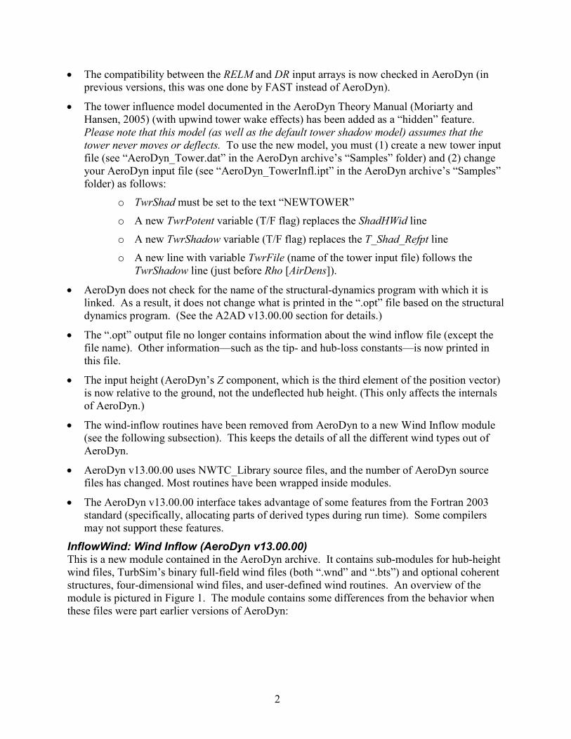
• The compatibility between the RELM and DR input arrays is now checked in AeroDyn (in previous versions, this was one done by FAST instead of AeroDyn).
• The tower influence model documented in the AeroDyn Theory Manual (Moriarty and Hansen, 2005) (with upwind tower wake effects) has been added as a “hidden” feature. Please note that this model (as well as the default tower shadow model) assumes that the tower never moves or deflects. To use the new model, you must (1) create a new tower input file (see “AeroDyn_Tower.dat” in the AeroDyn archive’s “Samples” folder) and (2) change your AeroDyn input file (see “AeroDyn_TowerInfl.ipt” in the AeroDyn archive’s “Samples” folder) as follows:
o TwrShad must be set to the text “NEWTOWER”
o A new TwrPotent variable (T/F flag) replaces the ShadHWid line
o A new TwrShadow variable (T/F flag) replaces the T_Shad_Refpt line
o A new line with variable TwrFile (name of the tower input file) follows the TwrShadow line (just before Rho [AirDens]).
• AeroDyn does not check for the name of the structural-dynamics program with which it is linked. As a result, it does not change what is printed in the “.opt” file based on the structural dynamics program. (See the A2AD v13.00.00 section for details.)
• The “.opt” output file no longer contains information about the wind inflow file (except the file name). Other information—such as the tip- and hub-loss constants—is now printed in this file.
• The input height (AeroDyn’s Z component, which is the third element of the position vector) is now relative to the ground, not the undeflected hub height. (This only affects the internals of AeroDyn.)
• The wind-inflow routines have been removed from AeroDyn to a new Wind Inflow module (see the following subsection). This keeps the details of all the different wind types out of AeroDyn.
• AeroDyn v13.00.00 uses NWTC_Library source files, and the number of AeroDyn source files has changed. Most routines have been wrapped inside modules.
• The AeroDyn v13.00.00 interface takes advantage of some features from the Fortran 2003 standard (specifically, allocating parts of derived types during run time). Some compilers may not support these features.
InflowWind: Wind Inflow (AeroDyn v13.00.00) This is a new module contained in the AeroDyn archive. It contains sub-modules for hub-height wind files, TurbSim’s binary full-field wind files (both “.wnd” and “.bts”) and optional coherent structures, four-dimensional wind files, and user-defined wind routines. An overview of the module is pictured in Figure 1. The module contains some differences from the behavior when these files were part earlier versions of AeroDyn:

3
Figure 1. Schematic of new Wind Inflow module, containing private sub-modules for binary full-
field (FF), hub-height (HH), user-defined (UserWind), coherent turbulence (CT), and four-dimensional (FD) wind types. AeroDyn will initialize the module by calling WindInf_Init(), get the velocity by calling WindInf_GetVelocity(), and when finished, call WindInf_Terminate() to
clean up the arrays and close any open files.
• TurbSim-format (“.bts”) files can now be used.
• Hub-height files are read in their entirety at the beginning of a simulation. The warning about reading the last record in the file does not exist anymore.
4
• The wind files (including hub-height files) must use the metric system.
• If the AeroDyn reference height (HH) is specified differently than the hub-height in TurbSim (HubHt), then full-field wind data applied in AeroDyn is now relative to TurbSim’s value (HubHt) (previously, AeroDyn’s value [HH] was used).
• The input height (Wind Inflow’s Z component, which is the third element of the position vector) is relative to the ground, not the undeflected hub height. (This only affects the internals of Wind Inflow.)
• The logic to determine the wind file type has changed:
o If the name of a wind file does not have an extension, it will be assumed to be a binary full-field file with a “.wnd” extension.
o If a “.sum” file with the same root name as a “.wnd” file exists, that “.wnd” file is assumed to be a full-field file. If a corresponding “.sum” file does not exist, a “.wnd” file is assumed to be a hub-height wind file. This functions as before, except in rare situations.
o Other wind file types are determined by their file extensions, so do not use extensions “.bts”, “.ctp”, “.cts”, “.twr”, or “.fdp” for your hub-height wind files.
• The tower binary files (“.twr”) with the same root name as the full-field binary “.wnd” files will always be read if they exist.
• In the coherent turbulence parameter (“.ctp”) files, the names of the “.cts” and “.wnd” files are now relative to the directory where the “.ctp” file is stored (unless the full path for the “.cts” and/or “.wnd” file is specified).
• The user-defined wind routine UserWind() from source file “UserWind.f90” has been replaced with a self-contained module in “UserWind.f90”.
FAST v7.00.00 The following items have changed relative to what is documented in the latest FAST User’s Guide for v6.01 (Jonkman and Buhl, 2005). The changes that also apply to the FAST-to-ADAMS preprocessor and A2AD v13.00.00 have been marked with “[Also ADAMS]”.
• This version is not backward compatible. That is, you cannot use FAST v7.00.00 to interface with a version of AeroDyn before AeroDyn v13.00.00.
• [Also ADAMS] Some of the validity checks on input parameters have been improved.
• [Also ADAMS] The number of available blade and tower gages (inputs NBlGages and NTwGages) has increased from 5 to 9, and gages are now available on all blades. New output parameters for the local loads and motions at the additional strain gages are named following the same convention as the outputs for the original 5 gages.
• [Also ADAMS] The offshore wind turbine modeling functionality of HydroDyn is included as an undocumented feature. We plan to release HydroDyn as a stand-alone hydrodynamics module, with its own user’s guide, in the future. For those already familiar with the offshore wind turbine modeling functionality that was available in FAST v6.02c-jmj and A2AD

5
v12.20c-jmj, the functionality is identical in FAST v7.00.00 and A2AD v13.00.00. For those not already familiar, the functionality is summarized in the footnote below.*
• [Also ADAMS] A bug in the “BladedDLLInterface.f90” source file was fixed so the loads and power are multiplied by 1000 instead of 0.001. Also an incompatibility with the “BladedDLLInterface.f90” source file and HSSBrMode = 2 was resolved.
• [Also ADAMS] The column headings for invalid channels have been changed to be the variable name, with the units line saying “INVALID.”
• A bug that produced bad FAST linearization output (“.lin”) file when GBoxEff was specified to be less than 100% was resolved.
• A new internal parameter has been added to make it easier to change the order of the polynomials used to specify the blade and tower mode shapes. To change the order, modify parameter PolyOrd in module Modes of “FAST_Mods.f90” and recompile FAST. To aid in obtaining the polynomial coefficients by curve-fitting externally provided mode shapes, an MS Excel workbook “ModeShapePolyFitting.xls” has been added to the FAST archive.
*HydroDyn in its present form applies to both fixed-bottom monopiles and floating platforms and has been tested by many users. So while the code is undocumented, it is well tested.
For floating platforms, the hydrodynamics and mooring system models are well documented in J. Jonkman’s 2009 Wind Energy journal article and 2007 PhD thesis-turned NREL report: http://www3.interscience.wiley.com/cgi-bin/fulltext/122464755/PDFSTART and http://www.nrel.gov/docs/fy08osti/41958.pdf.
For monopiles, no report is available that explains its capability. But to summarize: the monopile hydrodynamics model accounts for regular or irregular linear waves (with or without stretching) and sea currents and uses the relative form of Morison's equation for the load calculation. The wave data can be generated internally within the module, or by reading in (perhaps higher-order) wave data output from GH Bladed or some other wave kinematics code. (Because the module does not have a higher-order wave kinematics model built into it, if you want to model severe regular waves, you would have to use GH Bladed or some other wave kinematics code to generate the higher-order wave kinematics data before running a simulation with HydroDyn.
There are several models you can use to start playing with the new offshore features. In addition to the 17 sample wind turbine models (all onshore) provided in the archive of FAST v7.00.00, five models of the NREL 5-MW baseline wind turbine are available from here: http://wind.nrel.gov/public/jjonkman/NRELOffshrBsline5MW. These models include, the (1) onshore version of the 5-MW turbine, (2) the 5-MW turbine installed on a fixed-bottom monopile with rigid foundation in 20 m of water, (3) the 5-MW turbine installed on the floating ITI Energy barge (the floating platform J. Jonkman analyzed in his Ph.D. project), (4) the 5-MW turbine installed on a floating Tension Leg Platform, and (5) the 5-MW turbine installed on a floating spar-buoy (based on the OC3 project’s modifications to the Hywind concept). The archive for the model of the onshore version of the NREL 5-MW wind turbine includes a report that documents the turbine. The OC3 model requires a slightly customized version of HydroDyn, so, this model comes with its own FAST executable; this model also comes with a report that documents the platform.
Each of these models contains a torque and pitch controller in GH Bladed-style DLL format. These controllers require FAST’s interface to GH Bladed-style DLLs, which is not a default option in FAST v7.00.00. You can find a version of FAST with this interface here: http://wind.nrel.gov/public/jjonkman/FAST/FAST_v7.00.00a-bjj_AeroDyn_v13.00.00a-bjj_BladedDLLInterface.exe. Or if you’re adventurous, you can recompile FAST using the guidance found in the FAST User’s Guide.
All of the new offshore-related (hydrodynamic and mooring system) inputs are contained in the updated platform input files.
6
• The function that obtains CPU times has been replaced with an intrinsic (not-system-specific) function. This means the CPU times between old and new versions are not obtained in exactly the same way (beware of comparisons). “Total Real Time” is now calculated for the whole FAST run (instead of just the simulation portion), and the time ratio now is “simulated time” divided by “total CPU time.” Simulated CPU time is no longer printed.
• For the first time, the source files needed to compile the FAST S-Function for MATLAB/Simulink have been added to the archive. These—plus all of the Simulink-related files—have been included in the new “Simulink” directory of the FAST archive. The MATLAB script, “make_FAST_SFunc.m,” can be used to recompile the FAST S-Function. There are compiling instructions at the top of this script. Recompiling may be required to use the various versions of MATLAB. The S-Function has changed from “FAST_SFunc.dll” to “FAST_SFunc.mexw32” in MATLAB R2006a and newer.
• Most of the memory leaks in the FAST S-Function for MATLAB/Simulink have been eliminated, minimizing how often you must close and restart MATLAB after running a series of simulations.
• The FAST S-Function for MATLAB/Simulink now writes all of its messages to MATLAB’s Command Window (it does not create the file “console.txt”).
• A new batch file, called “Compile_FAST.bat,” is included in the archive. It compiles FAST from the command line using Intel Visual Fortran for Windows, but could be modified for other compilers.
• FAST v7.00.00 uses NWTC_Library source files, and the number of FAST source files has changed. Most routines have been wrapped inside modules. Please see “Compile_FAST.bat” in the FAST archive for the list of files and compile options (specifically, /assume:byterecl, /Qzero, and /Qsave) required to compile FAST with AeroDyn.
• The FAST certification test uses files from the MBC download to calculate system natural frequencies. Previous versions used a script called “Eigenanalysis.m,” which is no longer part of the archive. The MBC scripts should be used in place of “Eigenanalysis.m” in all situations.
• The format of FAST’s linearization output (“.lin”) file has changed to include data needed by the MBC scripts. Earlier linearization post-processing scripts may not be able to read in the new format. The MBC scripts should be used for all linearization post processing.
• A new script, called “Simulink_CertTest.m,” to run the certification test for the FAST S-Function for MATLAB/Simulink has been added to the archive.
• The results of the certification test can be plotted using the new “PlotCertTestResults.m” script in the FAST archive. An example of how to call the function in MATLAB is given below (set newPath to your FAST CertTest directory): newPath = 'D:\DATA\Fortran\IVF Projects\FAST\Release\CertTest'; oldPath = [newPath '\TstFiles']; PltFAST = true; PltAdams = true; PlotSimulink = true; PlotCertTestResults( newPath, oldPath, PltFAST, PltAdams, PlotSimulink);

7
• AeroDyn will generate an empty “<RootName>.elm” file when CompAero=FALSE in FAST
and the AeroDyn input file requests an “.elm” file. This should be fixed in a future version.
• The FAST echo file is now named “<RootName>.ech” instead of “echo.out”.
• The length of the input file names are now 1024 characters (most used to be limited to 99 characters).
ADAMS-to-AeroDyn (A2AD) v13.00.00 The following items have changed relative to what is documented in the latest A2AD User’s Guide for v12.19 (Laino and Hansen, 2001). Other changes that also apply to FAST are noted with “[Also ADAMS]” in the FAST v7.00.00 section above.
• This version is not backward compatible and is only compatible with ADAMS models generated by FAST v7.00.00. That is, you cannot use A2AD v13.00.00 with ADAMS models created by ADAMS/WT or by versions of FAST before FAST v7.00.00; and you can’t use A2AD v13.00.00 to interface an ADAMS model to a version of AeroDyn before AeroDyn v13.00.00. Instead of relying solely on the ADAMS statements (Markers, etc.) defined in A2AD User’s Guide (Laino and Hansen, 2001), A2AD v13.00.00 now uses many of the statements defined in the FAST-to-ADAMS documentation (“FAST2ADAMSStatements.xls”).
• Several of the variables needed by AeroDyn (rotor radius, tip- and hub-loss constants, local rotor radius, hub velocity due to yaw, etc.), which were estimated within A2AD’s “GFOSUB.f90” source file, now take advantage of the ADAMS statements created by the FAST-to-ADAMS preprocessor. This will influence the simulation results for models with a nonzero precone, initial nonzero teeter angle, and high yaw rates.
• AeroDyn now checks the RELM array (see comments in the AeroDyn v13.00.00 section, above). In previous versions, RELM was not used with A2AD.
• Gravity and structural damping are no longer disabled during ADAMS linearization of FAST-to-ADAMS created models.
• A2AD now checks that the version of A2AD is compatible with the version of FAST from which an ADAMS model was created.
• Messages from AeroDyn are written to the screen, but not to the MSC.ADAMS message (“.msg”) file. (That is, the MSC.ADAMS’ USRMES() and ERRMES() subroutines are not used anymore.)
• A2AD v13.00.00 uses NWTC_Library source files, and the number of A2AD source files has changed. Most routines have been wrapped inside modules. Please see “CompileLinkA2AD.bat” in the “DLL” (renamed from “Executable”) folder of the A2AD archive for the list of files and compile options (/assume:byterecl, /Qzero, and /Qsave, specifically) required to compile A2AD with AeroDyn.
• The AeroDyn “.opt” file will now be named “<RootName>.opt” instead of “gfosub.opt.”
• The (initial) rotor tilt angle will not be printed in the AeroDyn “.opt” file.
8
• The “Samples” folder has been eliminated from the archive. Because A2AD v13.00.00 is only compatible with FAST-to-ADAMS created ADAMS models, use the FAST certification test to generate sample models for ADAMS.
YawDyn and SymDyn These programs are no longer supported.
Updates in February 2012 Changes to FAST. AeroDyn (including InflowWind), and A2AD released in February 2012 should result in only negligible (if any) differences with previous simulation results.
FAST v7.01.00 These are changes relative to FAST v7.00.00, documented above.
• Several new outputs for internal DOFs, first time derivatives, and second time derivatives have been added. The Excel file, "OutListParameters.xlsx", in the FAST archive contains details on these outputs.
• [Also ADAMS] Several new outputs for local forces and deflections (relative to undeflected locations) in the blades and tower, and global tower positions (relative to the inertial frame) have been added. The Excel file, "OutListParameters.xlsx", in the FAST archive contains details on these outputs.
• [Also ADAMS] Relative file names in the input files are now considered relative to the directory containing the input file (not the current working directory).
• Datasets generated by the FAST2ADAMS pre-processor have been modified to contain new/renamed markers and arrays.
ADAMS-to-AeroDyn (A2AD) v13.01.00 These are changes relative to A2AD v13.00.00. Other changes that also apply to FAST are noted with “[Also ADAMS]” in the FAST v7.01.00 section above.
• The CompileLinkA2AD.bat script has been modified to include an option for the Bladed DLL, similar to the CompileFAST.bat script.
• The source code has been modified to use new/renamed markers and arrays.
AeroDyn v13.00.01 These are changes relative to AeroDyn v13.00.00.
• Relative file names in the input files are now considered relative to the directory containing the input file (not the current working directory).
• The tangential induction output in the *.elm file now contains the tangential induction instead of all zeros (bug fix).
• AeroDyn's InflowWind routines now allow HH wind files with only 1 line of data.

9
Updates in February 2013 Changes to FAST. AeroDyn (including InflowWind), and A2AD released in February 2013 should result in only negligible (if any) differences with previous simulation results.
Please note that these updated tools are NOT in the new FAST modularization framework Progress on converting to the new framework is taking place, and we anticipate releasing the first versions of these tools in the framework in the coming months. Because the process of converting all of the current features of the CAE tools will take some time, we plan to make FAST v7.02.00 available for an extended time (available concurrently with FAST 8.* in the new framework).
FAST v7.02.00 These are changes relative to FAST v7.01.00.
• A new option for creating binary output files was added to the FAST input file. A new input switch called “OutFileFmt” indicates if the tabular output should be (1) a text file, (2) a binary file, or (3) both text and binary files. All primary input files for FAST must be modified to include this new line. (See line 170 in the sample input files in the FAST archive’s CertTest folder.) The new FAST binary output files store the output channels as packed 16-bit integers, and the files can be read by Crunch v3.01.00d (and later) and MATLAB, using the ReadFASTbinary.m script included in the CertTest folder of the FAST archive.
• The input parameter “TMax” does not have the upper limit limitation of 9999.999 seconds when only binary tabular (time-marching) output is requested. The limit still exists for tabular text output.
• The CertTest (regression test) was modified to use Crunch v3.01.00 and to generate binary output files for Test04 and both text and binary output files for Test02.
• The FAST archive now contains a “Compiling” folder. The batch script to compile FAST on IVF for Windows® was moved there. We added a batch script to compile a DISCON.DLL using IVF for Windows®. We also added a makefile for compiling FAST using gfortran on Windows or Linux. (The makefile has been tested on Windows® 7 with gfortran 4.6.2 without the interface for the Bladed-style DLL; it has not been tested on Linux.)
• The FAST archive now contains a “Labview” folder. This folder contains a DLL that has been designed to run FAST in LabVIEW Real-Time 2012 SP1. The folder contains documentation, source code, a script for compiling the DLL, and an example for calling/running the DLL in LabVIEW. We assume anyone who uses this DLL is proficient with using LabVIEW software.
• The “user-defined from Simulink” setting available with the “YCMode,” “PCMode,” and “VSContrl” controls switches in the primary FAST input file is now “user-defined from Simulink or Labview.” The “HSSBrMode” switch in the primary FAST input file now includes an option (3) for “user-defined from Labview.” (The “HSSBrMode” switch is still unavailable for Simulink.)

10
• We fixed a couple of issues in the previous version of the code that prevented people from compiling/running the code in Debug mode (this did not affect results or running the executable version).
• We modified some text in the “OutListParameters.xlsx” file for clarity and correctness.
• The code has been updated to compile with NWTC Subroutine Library v1.07.00.
ADAMS-to-AeroDyn (A2AD) v13.01.00 The version number hasn’t changed; the compile script was adjusted to compile with AeroDyn v13.00.02 and NWTC Subroutine Library v1.07.00.
AeroDyn v13.00.02 These are changes relative to AeroDyn v13.00.01.
• The code has been updated to compile with NWTC Subroutine Library v1.07.00.
• The InflowWind module has been removed from AeroDyn and is now a separately distributed archive.

11
Description of the AeroDyn v13.00.* Interface
The AeroDyn overhaul is progressing in two paths: (1) developing a clear and streamlined interface between AeroDyn and the various structural-dynamic codes and (2) making the internals of AeroDyn much more modular such that new aerodynamic theories can be added in the future. The completion of AeroDyn v13.00.00 marks the completion of path (1). The modularization of AeroDyn with improved functionality from path (2) will come later.
The internal functionality of AeroDyn v13.00.00 is the same as AeroDyn v12.58 (with the exceptions noted above), but with an improved interface. AeroDyn v13.00.00 has been defined to streamline the interface with other codes and to encapsulate as many private data and methods (subroutines and functions) as possible. We cannot guarantee that changes will not be made in future versions of AeroDyn when we introduce new implementations of aerodynamic theories; however, effort has been made in this version to minimize the inconvenience of doing so.
To initialize AeroDyn v13.00.00, only one function is called (previously, multiple subroutines were used). An even bigger change with this new interface is that all the information AeroDyn requires to calculate loads is passed in one function call. This function is called only once per time step whereas previous versions called a subroutine to calculate loads at each element on each blade and each time step.
Data Types To organize data for the new interface, we have made use of derived data types. These types allow data to be organized in meaningful ways, and allow the data passed between codes to be added or deleted with minimal effort. The new shared data types are stored in the “SharedTypes.f90” source file in the “Source” folder of the AeroDyn archive.
Derived Types Marker and Load The basic data types for the interface are Marker and Load, which are defined in Fortran as:
TYPE, PUBLIC :: Marker REAL(ReKi) :: Position(3) REAL(ReKi) :: Orientation(3,3) ! Direction cosine matrix REAL(ReKi) :: TranslationVel(3) ! Translational velocity REAL(ReKi) :: RotationVel(3) ! Rotational velocity END TYPE Marker TYPE, PUBLIC :: Load REAL(ReKi) :: Force(3) REAL(ReKi) :: Moment(3) END TYPE Load
Note: The NWTC_Library’s Precision module declares ReKi as:
INTEGER, PARAMETER :: ReKi = 4 All markers in the AeroDyn v13.00.00 interface are body fixed; i.e., they move and orient themselves with the body they are attached to.

12
The positions are specified in units of meters, relative to the origin of the global X,Y,Z reference frame. X,Y,Z represents the set of orthogonal axes of an inertial reference frame fixed with respect to the undeflected tower centerline (mean location of the support platform for offshore systems), with the XY-plane designating the ground (or still water level [SWL] for offshore systems), the X axis pointing in the (nominally) downwind (zero degree wind) direction, the Y axis pointing to the left looking along the positive X axis, and the Z axis pointing vertically upward opposite gravity along the centerline of the undeflected tower (when the support platform is undisplaced for offshore systems).
The 3-component position vector is the origin of marker defined such that
X
Marker%Position YZ
=
.
The 3-component translational velocity vector is in units of meters per second and the 3-component rotational velocity vector is in units of radians per second. Both velocity vectors are relative to the inertial X,Y,Z reference frame.
The orientations are defined as 3-by-3 direction cosine matrices. The direction cosine matrix, D, rotates a vector defined in the inertial reference frame (upper case letters) to a vector with the same origin but defined in a reference frame parallel with the body-fixed reference frame (lower case letters):
x Xy D Yz Z
=
.
The matrix D must be orthonormal, i.e., D DT = I, where I is the 3-by-3 identity matrix. It is up to the user to make sure the matrices are orthonormal because AeroDyn v13.00.00 does not perform this check.
The loads include forces per unit length and moments per unit length in units of Newtons per meter and Newton-meters per meter.† The 3-component force and moment vectors are aligned with the local body-fixed marker for which the load is associated.
AeroDyn needs to have information about the turbine configuration and analysis nodes where the aerodynamic loads will be calculated. To pass this information, we’ve placed markers in every body that has a direct influence on the aerodynamic loads, and we’ve placed markers and loads at all analysis nodes. Each body has one reference marker defined by derived type AeroConfig and each body may have zero or more analysis node markers and loads defined by derived types
†The current version of AeroDyn applies strip theory along the primary axis (one dimension) of the blade. Future versions of AeroDyn may need analysis nodes for a mesh covering the blade’s surface. In this case, the forces and moments would be per unit area.

13
AllAeroMarkers and AllAeroLoads, respectively. The analysis node markers and loads can move relative to the reference marker of the body they are a part of if the body is not rigid.
Derived Type AeroConfig The AeroConfig type contains a reference marker for each body that has a direct influence on the aerodynamic loads. The marker positions are pictured in Figure 2 and listed below.
Figure 2. Schematic of AeroConfig data type. Markers give the configuration of the bodies which
can influence aerodynamic loads.
Blade(1)
Blade(2)
Hub
TailFin
Tower
Substructure
Foundation
Nacelle
BladeLength
RotorFurl

14
TYPE, PUBLIC :: AeroConfig TYPE(Marker), ALLOCATABLE :: Blade(:) REAL(ReKi) :: BladeLength TYPE(Marker) :: Hub TYPE(Marker) :: RotorFurl TYPE(Marker) :: Nacelle TYPE(Marker) :: TailFin TYPE(Marker) :: Tower TYPE(Marker) :: Substructure TYPE(Marker) :: Foundation END TYPE AeroConfig
These markers for the AeroConfig type must be defined for the undeflected system during initialization and must be body fixed during loads calculation. Their definitions are described in the subsections below.
Figure 3. Schematic of AeroConfig (black) and AllAeroMarkers%Blade (blue) markers for the NREL
5-MW Baseline Onshore Turbine. AeroDyn’s ground coordinate system is shown in red.

15
AeroConfig%Blade There is one AeroConfig%Blade marker for each blade on the turbine. The markers pitch with the blades, and their positions are at the blade roots.
• Position: Intersection of the blade’s pitch axis and the blade root.
• Orientation: o x axis: Orthogonal with y and z axes such that they form a right-handed coordinate
system (pointing to suction side).
o y axis: Pointing towards the trailing edge of the blade and parallel with the chord line at the zero-twist blade station.
o z axis: Pointing along the pitch axis towards the tip of the blade.
Figure 4. Schematic of AeroConfig%Blade markers for the NREL 5-MW Baseline Onshore Turbine.
16
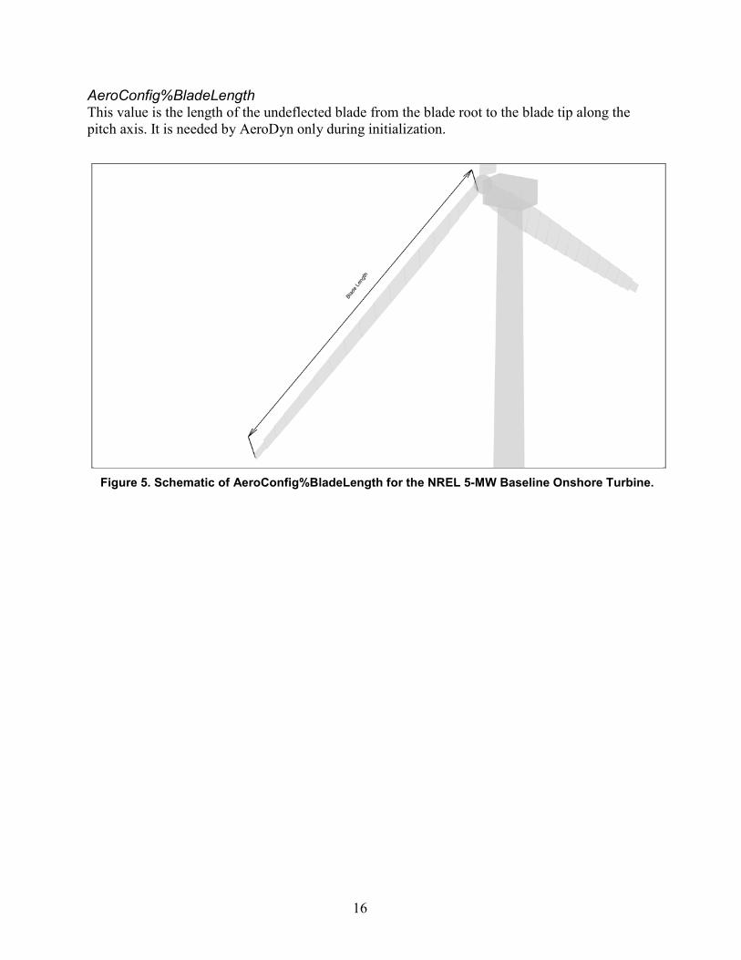
AeroConfig%BladeLength This value is the length of the undeflected blade from the blade root to the blade tip along the pitch axis. It is needed by AeroDyn only during initialization.
Figure 5. Schematic of AeroConfig%BladeLength for the NREL 5-MW Baseline Onshore Turbine.

17
AeroConfig%Hub The AeroConfig%Hub marker rotates with the rotor and teeters with the rotor in two-bladed models.
• Position: Location of the apex of rotation
• Orientation: o x axis: Pointing along the hub centerline in the nominally downwind direction.
o y axis: Orthogonal with the x and z axes such that they form a right-handed coordinate system.
o z axis: Perpendicular to the hub centerline with the same azimuth as Blade 1.
Figure 6. Schematic of AeroConfig%Hub marker for the NREL 5-MW Baseline Onshore Turbine.

18
AeroConfig%RotorFurl The AeroConfig%RotorFurl marker does not rotate with the rotor, but it does move with the tower, yaws with the nacelle, and furls with the rotor.
• Position: Location of the teeter pin for 2-bladed rotors or the apex of rotation for 3-bladed rotors.
• Orientation: o x axis: Pointing along the (possibly tilted) shaft in the nominally downwind
direction.
o y axis: Pointing to the left when looking from the tower toward the nominally downwind end of the nacelle.
o z axis: Orthogonal with the x and y axes such that they form a right-handed coordinate system.
Figure 7. Schematic of AeroConfig%RotorFurl marker for the NREL 5-MW Baseline Onshore
Turbine.

19
AeroConfig%Nacelle The AeroConfig%Nacelle marker moves with the top of the tower and yaws with the nacelle.
• Position: Intersection of the tower’s yaw axis and the yaw bearing.
• Orientation: o x axis: Pointing horizontally toward the nominally downwind end of the nacelle.
o y axis: Pointing to the left when looking toward the nominally downwind end of the nacelle.
o z axis: Coaxial with the tower/yaw axis and pointing up.
AeroConfig%TailFin This marker is not currently used.
Figure 8. Schematic of AeroConfig%Nacelle marker for the NREL 5-MW Baseline Onshore Turbine.

20
AeroConfig%Tower The AeroConfig%Tower marker is fixed in the base of the tower so that it translates and rotates with the tower base.
• Position: Intersection of the tower-base centerline and the tower-base connection to the substructure.
• Orientation: o x axis: Pointing horizontally in the nominally downwind direction.
o y axis: Pointing to the left when looking in the nominal downwind direction.
o z axis: Coaxial with the tower-base centerline and pointing up.
AeroConfig%Substructure This marker is not currently used.
AeroConfig%Foundation This marker is not currently used.
Figure 9. Schematic of AeroConfig%Tower marker for the NREL 5-MW Baseline Onshore Turbine.

21
Derived Types AllAeroMarkers and AllAeroLoads Types AllAeroMarkers and AllAeroLoads define the markers and loads at the aerodynamic analysis points. AeroDyn v13.00.00 calculates loads only in the blades, but in the future, versions will use the placeholders for loads calculated at the hub, rotor-furl, nacelle, tower, and tail fin:
TYPE, PUBLIC :: AllAeroMarkers TYPE(Marker), ALLOCATABLE :: Blade(:,:) TYPE(Marker), ALLOCATABLE :: Hub(:) TYPE(Marker), ALLOCATABLE :: RotorFurl(:) TYPE(Marker), ALLOCATABLE :: Nacelle(:) TYPE(Marker), ALLOCATABLE :: Tower(:) TYPE(Marker), ALLOCATABLE :: Tail(:) END TYPE AllAeroMarkers TYPE, PUBLIC :: AllAeroLoads TYPE(Load), ALLOCATABLE :: Blade(:,:) TYPE(Load), ALLOCATABLE :: Hub(:) TYPE(Load), ALLOCATABLE :: RotorFurl(:) TYPE(Load), ALLOCATABLE :: Nacelle(:) TYPE(Load), ALLOCATABLE :: Tower(:) TYPE(Load), ALLOCATABLE :: Tail(:) END TYPE AllAeroLoads
AllAeroMarkers%Blade There is one AllAeroMarkers%Blade marker at each aerodynamic analysis node on all blades of the turbine. The markers pitch and deflect with the blades, and their positions are at the center of the aerodynamic elements located by the RELM input in AeroDyn’s input file.
• Position: The location of the aerodynamic analysis node.
• Orientation: o x axis: Orthogonal with y and z axes such that they form a right-handed coordinate
system (pointing to suction side).
o y axis: Aligned with the local chord line pointing toward the trailing edge.
o z axis: Directed along the blade toward the tip.
AllAeroLoads%Blade There is one AllAeroLoads%Blade load associated with each AllAeroMarkers%Blade marker at each aerodynamic analysis node on all blades of the turbine. Their force and moment components are applied at the same position and orientation as the marker they are associated with.

22
Other Derived Types Other types are also defined for passing options to the functions to initialize AeroDyn and calculate aerodynamic loads. Those types are defined in the “AeroDyn.f90” source file and are discussed in this document with the methods that use them.
Public Methods The AeroDyn interface includes the following public methods: (1) function AD_Init() to initialize the necessary variables; (2) function AD_CalculateLoads() to calculate the aerodynamic loads at every time step; (3) subroutine AD_Terminate() to clean up after the program ends; and (4) functions AD_GetConstant(), AD_GetCurrentValue(), and AD_GetUndisturbedWind() to return values that might be needed by the structural code linked with AeroDyn. An overview of the module is shown in Figure 13 and the methods are described below.
Figure 10. Schematic of AllAeroMarkers%Blade markers for Blade 1 of the NREL 5-MW Baseline
Onshore Turbine. This blade has 17 aerodynamic analysis nodes.

23
AeroDyn Moduleuses many other internal modules, which should be private
Private (internal) data Private (internal) methods
Public data:AD_Prog%Name The name of this moduleAD_Prog%Ver The version (and date) of this module
Public methods:AD_Init Initialization function
Input: Name of the input file, <RootName> for the output file(s), option to write a summary file, turbine configuration markersOutput: Relative markers for aerodynamic loads, error status
AD_CalculateLoads Main function to calculate aerodynamic loadsInput: Current time, markers at locations to compute aerodynamic loads, turbine configuration markers, options for linearization and multiple airfoil table locationsOutput: Loads at the aerodynamic markers, error status
AD_GetConstant Function to return values that do not change with timeInput: Name of requested valueOutput: Requested constant, error status
AD_GetCurrentValue Function to return values of variables that change with timeInput: Name of requested valueOutput: Requested variable, error status
AD_GetUndisturbedWind Function to return the inflow wind speedInput: Time, position vectorOutput: Velocity vector, error status
AD_Terminate Subroutine to clean up internal variables and close filesOutput: Error status
Figure 11. Layout of AeroDyn v13.00.00 module.

24
AD_Init a function to initialize AeroDyn: it reads the input file, initializes the wind inflow module, and returns the markers of the aerodynamic discretization.
Syntax Result = AD_Init( AD_InitOptions_type, AeroConfig_type, ErrStat )
AD_InitOptions_type is a variable of derived data type AD_InitOptions, containing three components: (1) the name of the AeroDyn input file, (2) the root name which is used to name the output files (“.opt” and “.elm”), and (3) a true/false flag that determines if the AeroDyn “.opt” summary file should be generated. In the future, items may be added or removed from this data type. The definition in Fortran is
TYPE :: AD_InitOptions CHARACTER(1024) :: ADInputFile ! Name of the AeroDyn input file CHARACTER(1024) :: OutRootName ! Root name of AeroDyn output files LOGICAL :: WrSumFile ! Write an AeroDyn summary file? END TYPE AD_InitOptions
AeroConfig_type‡ is a variable of derived data type AeroConfig (defined in the Data Types section). The markers contained in it must be for the undeflected system.
ErrStat is a (default kind) INTEGER variable that indicates if an error was encountered during initialization. If an error is encountered, AeroDyn will return a non-zero ErrStat error code (in some instances AeroDyn will still abort the program, but in the future, we intend to have AeroDyn always send an error code to the calling program instead). The calling program should check ErrStat and end if appropriate.
‡To translate the interface data of AeroDyn v13.00.00 into information that was used in the AeroDyn v12.58 interface, AeroDyn v13.00.00 uses the AeroConfig_type variable to determine the following information during initialization:
• NumBlades = SIZE( AeroConfig_type%Blade(:) )
• HubRadius = DOT_PRODUCT(AeroConfig_type%Blade(1)%Position(:) - AeroConfig_type%Hub%Position(:), AeroConfig_type%Blade(1)%Orientation(3,:) )
• TipRadius = AeroConfig_type%BladeLength + HubRadius
• PreconeAngle = ASIN( DOT_PRODUCT(AeroConfig_type%Blade(1)%Orientation(3,:), AeroConfig_type%Hub%Orientation(1,:) ) )
Note if the AeroConfig_type%Blade markers for blades other than 1 give a different HubRadius or PreconeAngle, AeroDyn will write a warning to the screen.
Note also that FAST v7.00.00 calls this function using blade and hub markers relative to the hub (other markers are not defined). In future versions, we plan to change this so that the markers are passed in way defined in the Data Types section. In A2AD v13.00.00, blade and hub markers are correct, but no other markers are specified.

25
Result§ The result is a variable of derived data type AllAeroMarkers (defined in the Data Types section) containing positions and orientations of the aerodynamic markers relative to the blade root. The components of the AllAeroMarkers type are determined by the aerodynamic analysis node locations and corresponding aerodynamic twists. The markers contained in it are in the undeflected system with the positions and orientations relative to the blade root (defined in the input variable AeroConfig_type%Blade reference frame). The blade markers are a two-dimensional array of size (J, K), where J is the number of aerodynamic elements per blade (defined in AeroDyn’s input file) and K is the number of blades. The other components of the AllAeroMarkers type are not defined in v13.00.00 because AeroDyn currently computes loads on only the blade elements.
AD_CalculateLoads a function to calculate aerodynamic loads at the aerodynamic analysis markers determined in AD_Init().
Syntax Result = AD_CalculateLoads( CurrentTime, AllAeroMarkers_type, AeroConfig_type, CurrentADOptions, ErrStat )
CurrentTime** is a number of type REAL(ReKi) that tells AeroDyn the current time in the simulation.
§To translate the information that was used in the AeroDyn v12.58 to the interface data of AeroDyn v13.00.00, AeroDyn v13.00.00 defines the AD_Init() result to be the following:
( )00
( )Result%Blade J,K %Position
RELM J HubRadius
= −
( )( ) ( )( ) ( )
cos ( ) sin ( ) 0sin ( ) cos ( ) 0
0 0 1
TWIST J TWIST JResult%Blade J,K %Orientation TWIST J TWIST J
− =
In AeroDyn v13.00.00, the result for each element J on blade K is assumed to be equal for all blades.
**In AeroDyn v13.00.00, if the time from the previous aerodynamic load calculations is at least DTAero (the aerodynamic time step defined in AeroDyn’s input file), new loads will be calculated; otherwise it returns the previously calculated loads. This CurrentTime variable allowed us to remove AeroDyn’s timing variables from the structural code, making AeroDyn responsible for determining if aerodynamic loads should be calculated.

26
AllAeroMarkers_type†† is a variable of derived type AllAeroMarkers (defined in the Data Types section) that tells AeroDyn the current motion of the markers for the aerodynamic loads. AeroDyn v13.00.00 does not check the size of the components, but it assumes they are the same size as the result of
††To translate the interface data of AeroDyn v13.00.00 into information that was used in the AeroDyn v12.58 interface, AeroDyn v13.00.00 uses the AllAeroMarkers_type and AeroConfig_type variables to determine the following information at each new aerodynamic time step:
• RotorSpeed = ABS( DOT_PRODUCT(AeroConfig_type%Hub%RotationVel(:) - AeroConfig_type%RotorFurl%RotationVel(:), AeroConfig_type%Hub%Orientation(1,:) ) )
• YawAngle = ATAN2( -1.* AeroConfig_type%RotorFurl%Orientation(1,2), AeroConfig_type%RotorFurl%Orientation(1,1) )
• AvgVelNacelleRotorFurlYaw = AeroConfig_type%RotorFurl%RotationVel(3) –
AeroConfig_type%Nacelle%RotationVel(3)
AvgVelTowerBaseNacelleYaw = AeroConfig_type%Nacelle%RotationVel(3) - AeroConfig_type%Tower%RotationVel(3)
AvgVelTowerBaseYaw = AeroConfig_type%Tower%RotationVel(3)
rRotorFurlHub(1:2) = AeroConfig_type%Hub%Position(1:2) - AeroConfig_type%RotorFurl%Position(1:2)
rNacelleHub(1:2) = AeroConfig_type%Hub%Position(1:2) - AeroConfig_type%Nacelle%Position(1:2)
rTowerBaseHub(1:2) = AeroConfig_type%Hub%Position(1:2) - AeroConfig_type%Tower%Position(1:2)
HubVDue2Yaw = ( AvgVelNacelleRotorFurlYaw * rRotorFurlHub(2) + AvgVelTowerBaseNacelleYaw * rNacelleHub(2) + AvgVelTowerBaseYaw * rTowerBaseHub(2) ) * SIN(YawAngle) - ( AvgVelNacelleRotorFurlYaw * rRotorFurlHub(1) + AvgVelTowerBaseNacelleYaw * rNacelleHub(1) + AvgVelTowerBaseYaw * rTowerBaseHub(1) ) * COS(YawAngle)
• TiltAngle = ATAN2( AeroConfig_type%RotorFurl%Orientation(1,3), SQRT( AeroConfig_type%RotorFurl%Orientation(1,1)**2 + AeroConfig_type%RotorFurl%Orientation(1,2)**2 ) )
• AzimuthAngle(K) = ATAN2( -1.*DOT_PRODUCT(AeroConfig_type%Hub%Orientation(3,:), AeroConfig_type%RotorFurl%Orientation(2,:) ), DOT_PRODUCT(AeroConfig_type%Hub%Orientation(3,:), AeroConfig_type%RotorFurl%Orientation(3,:) ) ) + pi + (K - 1)*TwoPiNB
• ElementPitch(J,K) = -1.*ATAN2( -1.*DOT_PRODUCT( AeroConfig_type%Blade(K)%Orientation(1,:), AllAeroMarkers_type%Blade(J,K)%Orientation(2,:) ) , DOT_PRODUCT( AeroConfig_type%Blade(K)%Orientation(1,:), AllAeroMarkers_type%Blade(J,K)%Orientation(1,:) ) )
• tmpVector = AllAeroMarkers_type%Blade(J,K)%Position(:) - AeroConfig_type%Hub%Position(:)
rLocal(J,K) = SQRT( DOT_PRODUCT( tmpVector, AeroConfig_type%Hub%Orientation(2,:) )**2 + DOT_PRODUCT( tmpVector, AeroConfig_type%Hub%Orientation(3,:) )**2 )
Note that to get the same answers as AeroDyn v12.58, (1) RotorSpeed is calculated by subtracting the AeroConfig_type%RotorFurl rotational velocity, but AeroConfig_type%RotorFurl should not be needed in general; (2) YawAngle and TiltAngle use AeroConfig_type%RotorFurl instead of AeroConfig_type%Hub; and (3) the AzimuthAngle calculation uses the equation above, instead of one using AeroConfig_type%Blade markers.

27
AD_Init(). The markers contained in it must be defined for the body-fixed system. Currently, only the markers on the blades are defined.
AeroConfig_type††,‡‡ is a variable of derived data type AeroConfig (defined in the Data Types section) that tells AeroDyn the current configuration of each turbine body that has influence on the aerodynamic loads. The markers contained in it must be defined for the body fixed system.
CurrentADOptions A variable of type AeroLoadsOptions, defined below, sets some options, including whether or not the multiple airfoil table location option is used and if this is a linearization step.
TYPE, PUBLIC :: AeroLoadsOptions LOGICAL, ALLOCATABLE :: SetMulTabLoc(:,:) REAL(ReKi),ALLOCATABLE :: MulTabLoc(:,:) ! multiple airfoil table location LOGICAL :: LinearizeFlag END TYPE AeroLoadsOptions
The SetMulTabLoc component should be the same size as the AllAeroMarkers_type%Blade component. For each blade element, AeroDyn checks if this option is used. If it is TRUE, AeroDyn uses the value in the corresponding blade element of the MulTabLoc component array. These two components of the AeroLoadsOptions type keep the functionality of AeroDyn’s previous MulTabLoc variable. Most users can set SetMulTabLoc(:,:) = FALSE.
The LinearizeFlag component tells AeroDyn to calculate aerodynamic loads—even if the difference between the CurrentTime and the last time loads were calculated is not greater than AeroDyn’s DTAero input parameter. This should only be TRUE during model linearization.
ErrStat is a (default kind) INTEGER variable that indicates if an error was encountered in the function. If an error is encountered, AeroDyn will return a non-zero ErrStat error code (in some instances AeroDyn will still abort the program, but in the future, we intend to have AeroDyn always send an error code to the calling program instead). The calling program should check ErrStat and end if appropriate.
‡‡Note that to get the same results in FAST v7.00.00 and A2AD v13.00.00 as were obtained with AeroDyn v12.58, not all of the AeroConfig_type markers are passed in the way defined in the Data Types section:
• The AeroConfig_type%Blade orientations are passed using the coned system instead of the pitched system because AeroDyn v12.58 calculates forces normal and tangential to the cone of rotation.
• The AeroConfig_type%Hub marker is passed using the shaft tip frame instead of the hub frame because AeroDyn v12.58 treats teeter deflections like blade deflections.
• The AeroConfig_type%RotorFurl position is defined using a point on the rotor-furl axis instead of the shaft tip because of AeroDyn v12.58’s definition of HubVDue2Yaw (hub velocity due solely to yaw).
• The AeroConfig_type%Tower position is defined using the body-fixed platform reference point instead of a point at the base of the tower because of AeroDyn v12.58’s definition of HubVDue2Yaw.
28
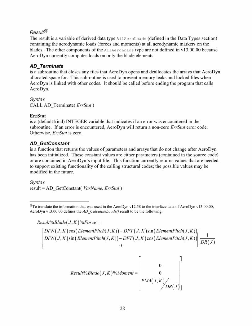
Result§§ The result is a variable of derived data type AllAeroLoads (defined in the Data Types section) containing the aerodynamic loads (forces and moments) at all aerodynamic markers on the blades. The other components of the AllAeroLoads type are not defined in v13.00.00 because AeroDyn currently computes loads on only the blade elements.
AD_Terminate is a subroutine that closes any files that AeroDyn opens and deallocates the arrays that AeroDyn allocated space for. This subroutine is used to prevent memory leaks and locked files when AeroDyn is linked with other codes. It should be called before ending the program that calls AeroDyn.
Syntax CALL AD_Terminate( ErrStat )
ErrStat is a (default kind) INTEGER variable that indicates if an error was encountered in the subroutine. If an error is encountered, AeroDyn will return a non-zero ErrStat error code. Otherwise, ErrStat is zero.
AD_GetConstant is a function that returns the values of parameters and arrays that do not change after AeroDyn has been initialized. These constant values are either parameters (contained in the source code) or are contained in AeroDyn’s input file. This function currently returns values that are needed to support existing functionality of the calling structural codes; the possible values may be modified in the future.
Syntax result = AD_GetConstant( VarName, ErrStat )
§§To translate the information that was used in the AeroDyn v12.58 to the interface data of AeroDyn v13.00.00, AeroDyn v13.00.00 defines the AD_CalculateLoads() result to be the following:
( )( ) ( ) ( ) ( )( ) ( ) ( ) ( ) ( )
% , %
, cos ( , ) , sin ( , )1, sin ( , ) , cos ( , )
0
Result Blade J K Force
DFN J K ElementPitch J K DFT J K ElementPitch J KDFN J K ElementPitch J K DFT J K ElementPitch J K
DR J
=
+ −
( )( )
( )
0% , % 0
,Result Blade J K Moment
PMA J KDR J
=

29
VarName is a character string input indicating the name of the requested variable. Valid entries are listed in Table 1.
ErrStat is a (default kind) INTEGER variable that indicates if an error was encountered. ErrStat is zero if there was no error; otherwise AeroDyn will return a non-zero ErrStat error code. The calling program should check ErrStat to determine if the result is meaningful.
Result The result is a number of type REAL(ReKi) containing the requested value.
AD_GetCurrentValue is a function that returns the values of parameters and arrays that depend on AeroDyn’s current state. This function currently returns values that are needed to support existing functionality of the calling structural codes; the possible values may be modified in the future.
Syntax result = AD_GetCurrentValue( VarName, ErrStat [, IBlade] [, IElem] )
VarName is a character string input indicating the name of the requested variable. Valid entries are listed in Table 2.
Table 2. List of Valid VarName Values in Function AD_GetCurrentValue().
VarName Returned value AVGINFL
AVGINFLOW The average induced inflow across the rotor disc for the previous time step (used for tail fin aerodynamics).
W2 W2(IElem, IBlade) (used for FAST’s noise routines)
ALPHA Alpha(IElem, IBlade): angle of attack for element IElem of blade IBlade (used for FAST’s noise routines).
Table 1. List of Valid VarName Values in Function AD_GetConstant().
VarName Returned value UNADIN ADUNIT Unit number of AeroDyn input file.
REFHT HH The wind reference height defined in the AeroDyn input file.
DT DTAERO AeroDyn time step.
AIRDENSITY RHO Air density.
KINVISC Kinetic viscosity.

30
ErrStat is a (default kind) INTEGER variable that indicates if an error was encountered. ErrStat is zero if there was no error; otherwise AeroDyn will return a non-zero ErrStat error code. The calling program should check ErrStat to determine if the result is meaningful.
IBlade is a (default kind) INTEGER variable that indicates the index for the blade, if the returned value is part of an array.
IElem is a (default kind) INTEGER variable that indicates the index for the blade element, if the returned value is part of an array.
Result The result is a number of type REAL(ReKi) containing the requested value.
AD_GetUndisturbedWind is a function that can be used to return the undisturbed wind speeds at any position and time for which the wind is defined.
Syntax result = AD_GetUndisturbedWind( Time, InputPosition, ErrStat )
Time is a number of type REAL(ReKi) that indicates the time in seconds from the start of the simulation when wind speeds are desired. (This time can differ from the current simulation time.)
InputPosition is an array with three elements of type REAL(ReKi). This array is the position vector defined in units of meters relative to the origin of the X,Y,Z reference frame.
ErrStat is a (default kind) INTEGER variable that indicates if an error was encountered. ErrStat is zero if there was no error; otherwise AeroDyn will return a non-zero ErrStat error code. The calling program should check ErrStat to determine if the result is meaningful.
Result The result is an array with three elements of type REAL(ReKi). The returned array contains the U-, V-, and W- component wind speeds at the specified time and location, which are not affected by the turbine wake or any other disturbances. These velocities are aligned with the inertial X,Y,Z coordinate system and are in units of meters per second.
Issues That Must Be Resolved in Later Versions of the AeroDyn Interface The interface to AeroDyn v13.00.00 has not completely resolved all of the issues that we hope to address. To be fully modular, we need to keep the module’s internal details encapsulated, limiting the ways that the structural routines are allowed to access AeroDyn’s data and methods. Some of the remaining issues are:

31
• The structural codes call CLCD() for tail fin aerodynamics. We hope to include the tail fin aerodynamics in AeroDyn in a future release, removing the need for other codes to call this internal AeroDyn subroutine.
• The structural codes call ElemOut() to write the output to AeroDyn’s “<RootName>.elm” file. AeroDyn should handle its own output files.
• FAST checks for an instability in the dynamic inflow calculations and the turns off AeroDyn’s DYNIN switch if necessary. AeroDyn needs to fix this instability.
• FAST’s Input() routine uses AeroDyn variables to check for valid inputs. This is done mostly for linearization. Linearization functionality should be added to AeroDyn.
• The MulTabLoc option passed from the structural code has not been tested. We plan to replace the functionality of MulTabLoc with improved aerodynamics controls functionality in a future version of AeroDyn.
• FAST requires the Chord array from AeroDyn’s input file. Chord is used for AeroCent, ADAMS graphics, and the Noise module.
• The linearization routines in FAST required some modifications to the wind-inflow module. We may make a new input file for the wind inflow that could deal with linearization.
• AeroDyn’s DiskVel() subroutine currently uses knowledge of the wind-inflow file type to calculate an “average” rotor-disk velocity. We want to remove this requirement so that the average velocity does not change with different wind file types.
• AeroDyn checks that the mean velocity in binary full-field wind files is at least 8 meters per second before allowing dynamic inflow to be used. (This check is not done for other wind file types.) We do not want AeroDyn to check for specific wind file types.
Ongoing Work
Please note that as of 2013, we are working to implement the new FAST modularization framework. The framework will address the outstanding issues listed above as well as add many new features, but it will take some time to fully implement.