Embed Size (px)
Citation preview

College of Engineering
NRC MOV Course
MOV Controls
College of Engineering
MOV Controls
Objectives
• Describe the operation and standard electrical circuits for both torque and limit controlled valves.
• Describe the electrical and mechanical components that make up typical motor actuator controls.
• Determine proper motor actuator control switch set points.

College of Engineering
Limitorque Electrical Controls

College of Engineering
Typical Wiring Diagram

College of Engineering
Components
• Power Supply – supply the energy required to operate the MOV
• Motor – converts electrical power to mechanical power. Reversing any two leads will reverse the direction of motor rotation.
• Overload Heater Coils (Thermal Overload Relays) – protect the motor in the event of excessive motor current.
• Reversing Starter – two separate functions
– Interchange power leads which change the direction of motor rotation
– Provide mechanical and electrical interlocks that prevent the contacts for both directions being closed at the same time
College of Engineering
Components - Continued
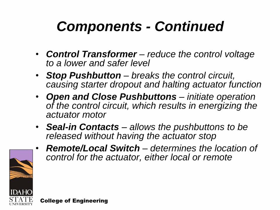
• Control Transformer – reduce the control voltage to a lower and safer level
• Stop Pushbutton – breaks the control circuit, causing starter dropout and halting actuator function
• Open and Close Pushbuttons – initiate operation of the control circuit, which results in energizing the actuator motor
• Seal-in Contacts – allows the pushbuttons to be released without having the actuator stop
• Remote/Local Switch – determines the location of control for the actuator, either local or remote

College of Engineering
Components - Continued
• Overload Contacts – protect the circuit from an overload condition by interrupting the control circuit
• Electrical Interlock Contacts – part of the contactor auxiliary contacts, prevent both the open and close contactors from operating at the same time
• Lights – provide approximate valve position information to plant operators

College of Engineering
Geared Limit Switch
• The geared limit switch counts the rotation of the drive sleeve or worm shaft in order to keep track of valve position.
– Shut off power to the actuator motor at the proper stroke position
– Turn indicating lights on and off and the proper stroke position
– Provide electrical interlocks and bypasses as required

College of Engineering
Standard Limit Switch

College of Engineering
Four-Train Limit Switch

College of Engineering
Limit Switch Control Functions
(View From Bottom
of the Limit Switch)

College of Engineering
Limit Switch Setting
• Each rotor is set separately for a particular valve stroke position
• The valve must be moved to the desired stroke position and then the limit switch rotor set.

College of Engineering
End View of Rotors

College of Engineering
Limit Switch Conditions
(View From Bottom
of the Limit Switch)

College of Engineering
Torque Switch
The torque switch has two possible functions
• On torque controlled valves, it is used to ensure that the valve has sufficient torque applied to the valve stem to guarantee seating
• On limit controlled valves, it is used to ensure that the actuator and valve are protected from possible excessive torque

College of Engineering
Leaf Type Torque Switch

College of Engineering
Knee Type Torque Switch
(Old Style)

College of Engineering
Knee Type Torque Switch
(New Style)

College of Engineering
Actuator Motors
• High rated starting torque
– Sized to provide the the torque required by the valve
– Delivers this torque over a relative short time period
• Short duty cycle
– For ac – 15 minutes
– For dc – 5 minutes
• Totally enclosed non-ventilated (TENV)

College of Engineering
Typical ac Motors
• Three phase, 230/460 VAC, squirrel cage induction motors
• Factory lubricated sealed bearings
• Three insulation classes
– Class B – 125°C, mild environment
– Class RH – 175°C, harsh environment
– Class LR – 250°C, very high temperature, harsh environments
• Three speeds – 900, 1800, 3600 rpm

College of Engineering
Typical ac Motor
Performance
Curve

College of Engineering
Typical dc Motors
• 125/250V dc compound-wound motors
• A compound-wound motor is a compromise between
– Shunt-wound motor – good speed regulation
– Series-wound motor – higher starting torque, but poor speed regulation
• Motor speed is inversely related to torque. Speed may be 2300 rpm at no load and 1550 at 20% load.

College of Engineering
Typical dc Motor
Performance
Curve

College of Engineering
Rotork Electrical Controls

College of Engineering
Rotork Components
• Motor – Three phase, 220 VAC, squirrel cage induction motors. A winding thermostat is included in the “A” range and “NA-4” actuators for overload protection.
– Class B – 125°C
– Class F – 155°C
– Class H – 175°C
• Starter – Houses mechanically and electrically interlocked reversing contactors
– Two normally open auxiliary contacts
– Opening and closing coils
– Fused control transformer.

College of Engineering
Rotork Components - Continued
• Integral Controls – open/stop/close pushbutton with lockable local/off/remote selector switch.
• Position Indication – mechanical three-position indicator shows open, intermediate, and closed conditions.
• Torque and Limit Switches – open and close torque or position limit switches plus two auxiliary limit switches at each end of travel.

College of Engineering
Syncropak Electrical Schematic
College of Engineering
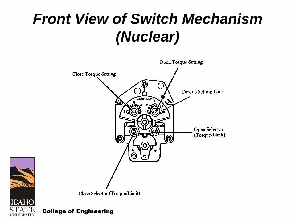
Front View of Switch Mechanism
(Nuclear)

College of Engineering
Switch Mechanism (Nuclear)

College of Engineering
Cross Section of Limit Switch
Assembly

College of Engineering
Typical Limit Switch Drive
Arrangements

College of Engineering
Switch Terminal Connections
(Nuclear)