Embed Size (px)
Citation preview
NRC Engagement(ATF Fuel)
CASL Industry CouncilRaleigh, NC
April 23, 2019
Jason HalesCASL Deputy Director
2
Acknowledgements
3
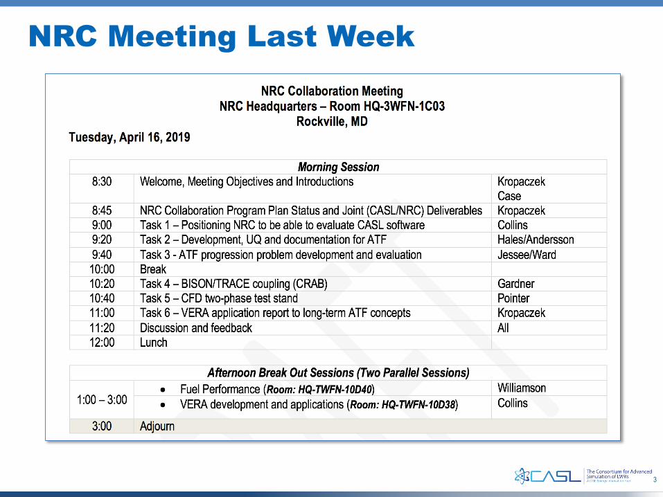
NRC Meeting Last Week
4
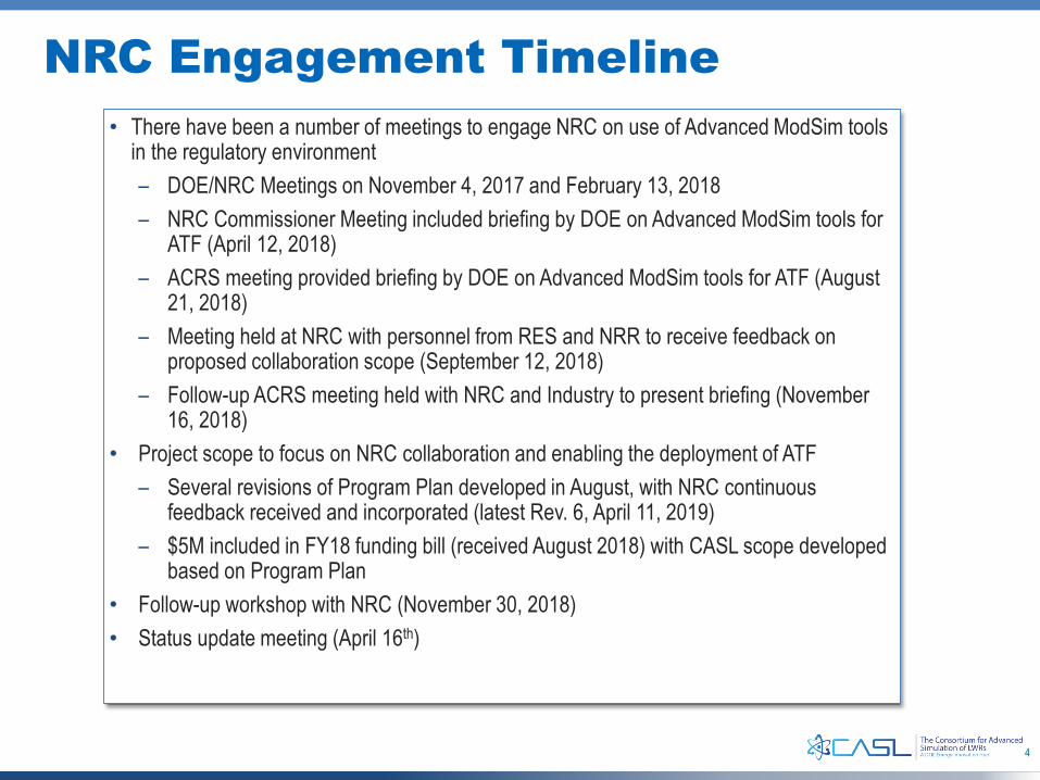
• There have been a number of meetings to engage NRC on use of Advanced ModSim tools in the regulatory environment– DOE/NRC Meetings on November 4, 2017 and February 13, 2018– NRC Commissioner Meeting included briefing by DOE on Advanced ModSim tools for
ATF (April 12, 2018)– ACRS meeting provided briefing by DOE on Advanced ModSim tools for ATF (August
21, 2018)– Meeting held at NRC with personnel from RES and NRR to receive feedback on
proposed collaboration scope (September 12, 2018)– Follow-up ACRS meeting held with NRC and Industry to present briefing (November
16, 2018)• Project scope to focus on NRC collaboration and enabling the deployment of ATF
– Several revisions of Program Plan developed in August, with NRC continuous feedback received and incorporated (latest Rev. 6, April 11, 2019)
– $5M included in FY18 funding bill (received August 2018) with CASL scope developed based on Program Plan
• Follow-up workshop with NRC (November 30, 2018)• Status update meeting (April 16th)
NRC Engagement Timeline
5
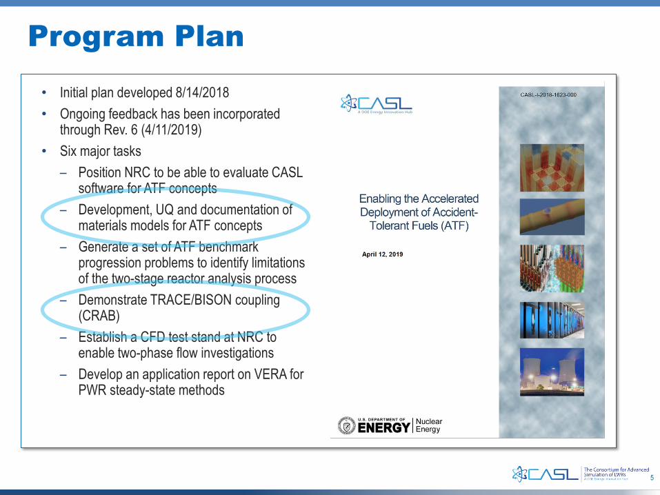
• Initial plan developed 8/14/2018• Ongoing feedback has been incorporated
through Rev. 6 (4/11/2019)• Six major tasks
– Position NRC to be able to evaluate CASL software for ATF concepts
– Development, UQ and documentation of materials models for ATF concepts
– Generate a set of ATF benchmark progression problems to identify limitations of the two-stage reactor analysis process
– Demonstrate TRACE/BISON coupling (CRAB)
– Establish a CFD test stand at NRC to enable two-phase flow investigations
– Develop an application report on VERA for PWR steady-state methods
Program Plan
6
CASL Trains NRC Staff at VERA Users Group Meeting
• First Ever Virtual Environment for Reactor Applications (VERA) Users Group Meeting hosted at ORNL on February 11-15, 2019– Day 1 – VERA Workshop
• Methods and Technology Overview
– Day 2• VERA Users Group Meeting
– Day 3-5 – VERA Training• Hands-on exercises on using VERA for commercial applications
• 68 attendees from 26 different organizations– 2/3rd representing commercial nuclear power industry– Attendees received VERA 4.0 licenses and computer accounts
• 26 presentations from CASL staff members
• Seamless, exclusive access to INL’s Lemhi HPC resource for training (20,160 cores)
Very successful deployment of CASL-developed technology to the nuclear
industry including NRC
VERA Workshop February 11, 2019 at NTRC-3
VERA Users Group Meeting February 12, 2019 at ORNL
7
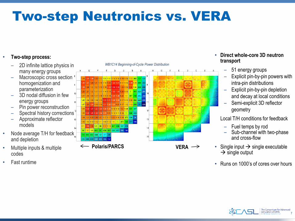
• Direct whole-core 3D neutron transport
– 51 energy groups– Explicit pin-by-pin powers with
intra-pin distributions– Explicit pin-by-pin depletion
and decay at local conditions– Semi-explicit 3D reflector
geometry• Local T/H conditions for feedback
– Fuel temps by rod– Sub-channel with two-phase
and cross-flow• Single input single executable single output
• Runs on 1000’s of cores over hours
Polaris/PARCS VERA
• Two-step process:– 2D infinite lattice physics in
many energy groups– Macroscopic cross section
homogenization and parameterization
– 3D nodal diffusion in few energy groups
– Pin power reconstruction– Spectral history corrections– Approximate reflector
models• Node average T/H for feedback
and depletion• Multiple inputs & multiple
codes• Fast runtime
WB1C14 Beginning-of-Cycle Power Distribution
Two-step Neutronics vs. VERA
8
ATF Modeling Charter and Approach
Analytical theory
9
Development, Uncertainty Quantification, and Documentation of Materials Models for ATF Concepts
• Further development and validation of ATF material models based on already established and ongoing discussions with NRC personnel to identify gaps and establish priorities. This work will build on earlier efforts under the NEAMS High-Impact Problem (HIP) on ATF. All development and validation work will be reported in detail within the existing Bison documentation system.
• For a selection of ATF material models, use modern UQ methodologies to develop uncertainty and range of validity estimates. Results will be reported using an approach similar to that documented for FRAPCON in NUREG/CR-7024.
• Compile and document publicly available empirical data and multiscale models for ATF concepts applicable for implementation in both the Bison and NRC FAST fuel performance codes.
• LLS work is prioritized according to concept maturity, gap and sensitivity analysis as well as highest impact of modeling (difficult experiments and, somewhat, mature modeling).
10
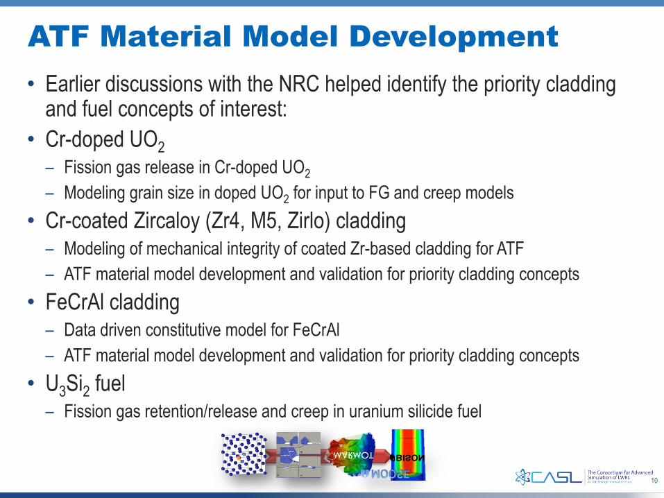
ATF Material Model Development• Earlier discussions with the NRC helped identify the priority cladding
and fuel concepts of interest:• Cr-doped UO2
– Fission gas release in Cr-doped UO2– Modeling grain size in doped UO2 for input to FG and creep models
• Cr-coated Zircaloy (Zr4, M5, Zirlo) cladding– Modeling of mechanical integrity of coated Zr-based cladding for ATF– ATF material model development and validation for priority cladding concepts
• FeCrAl cladding– Data driven constitutive model for FeCrAl– ATF material model development and validation for priority cladding concepts
• U3Si2 fuel– Fission gas retention/release and creep in uranium silicide fuel
Cr-doped UO2
12
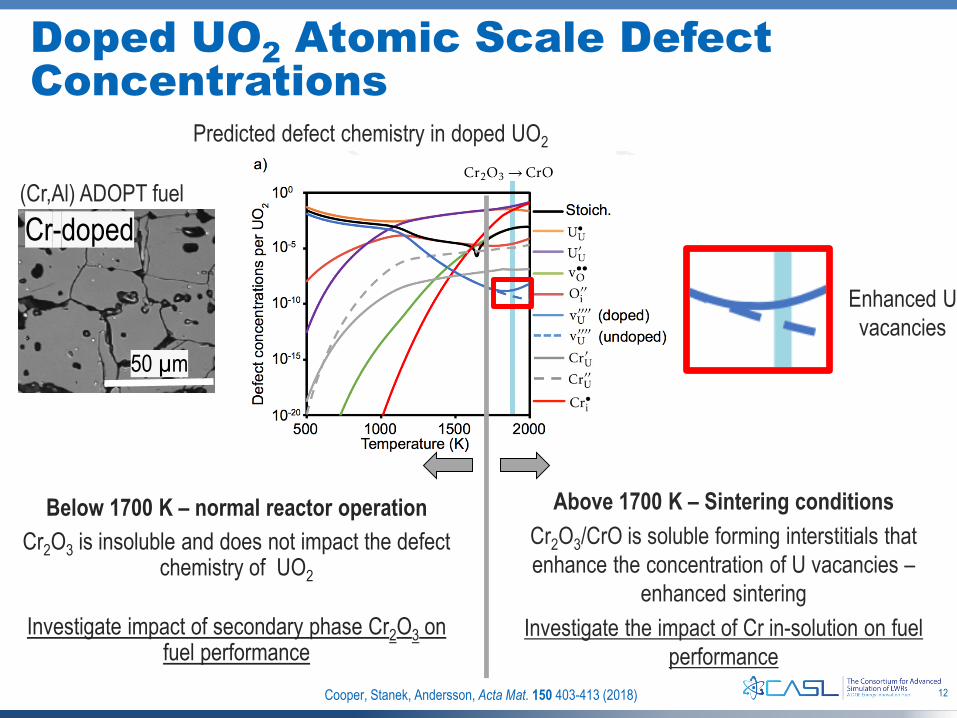
Doped UO2 Atomic Scale Defect Concentrations
Cr-doped
50 µm
Below 1700 K – normal reactor operationCr2O3 is insoluble and does not impact the defect
chemistry of UO2
Investigate impact of secondary phase Cr2O3 on fuel performance
Above 1700 K – Sintering conditionsCr2O3/CrO is soluble forming interstitials that enhance the concentration of U vacancies –
enhanced sinteringInvestigate the impact of Cr in-solution on fuel
performance
Predicted defect chemistry in doped UO2
(Cr,Al) ADOPT fuel
Enhanced U vacancies
Cooper, Stanek, Andersson, Acta Mat. 150 403-413 (2018)
13
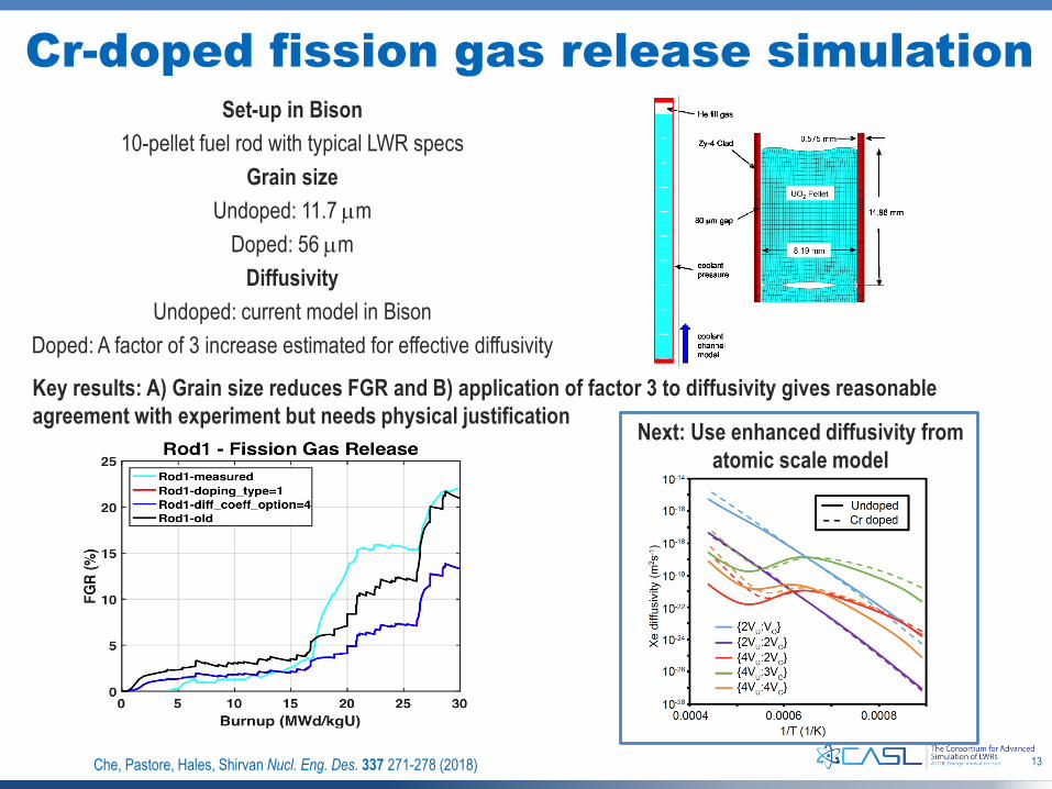
Cr-doped fission gas release simulationSet-up in Bison
10-pellet fuel rod with typical LWR specsGrain size
Undoped: 11.7 µmDoped: 56 µm
DiffusivityUndoped: current model in Bison
Doped: A factor of 3 increase estimated for effective diffusivity
Key results: A) Grain size reduces FGR and B) application of factor 3 to diffusivity gives reasonable agreement with experiment but needs physical justification
Che, Pastore, Hales, Shirvan Nucl. Eng. Des. 337 271-278 (2018)
Next: Use enhanced diffusivity from atomic scale model
14
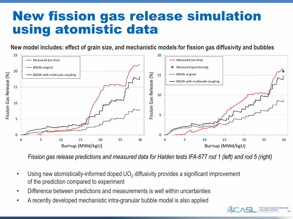
New fission gas release simulation using atomistic data
• Using new atomistically-informed doped UO2 diffusivity provides a significant improvement of the prediction compared to experiment
• Difference between predictions and measurements is well within uncertainties• A recently developed mechanistic intra-granular bubble model is also applied
New model includes: effect of grain size, and mechanistic models for fission gas diffusivity and bubbles
Fission gas release predictions and measured data for Halden tests IFA-677 rod 1 (left) and rod 5 (right)
DEPARTMENT OF MATERIALS SCIENCE AND ENGINEERING
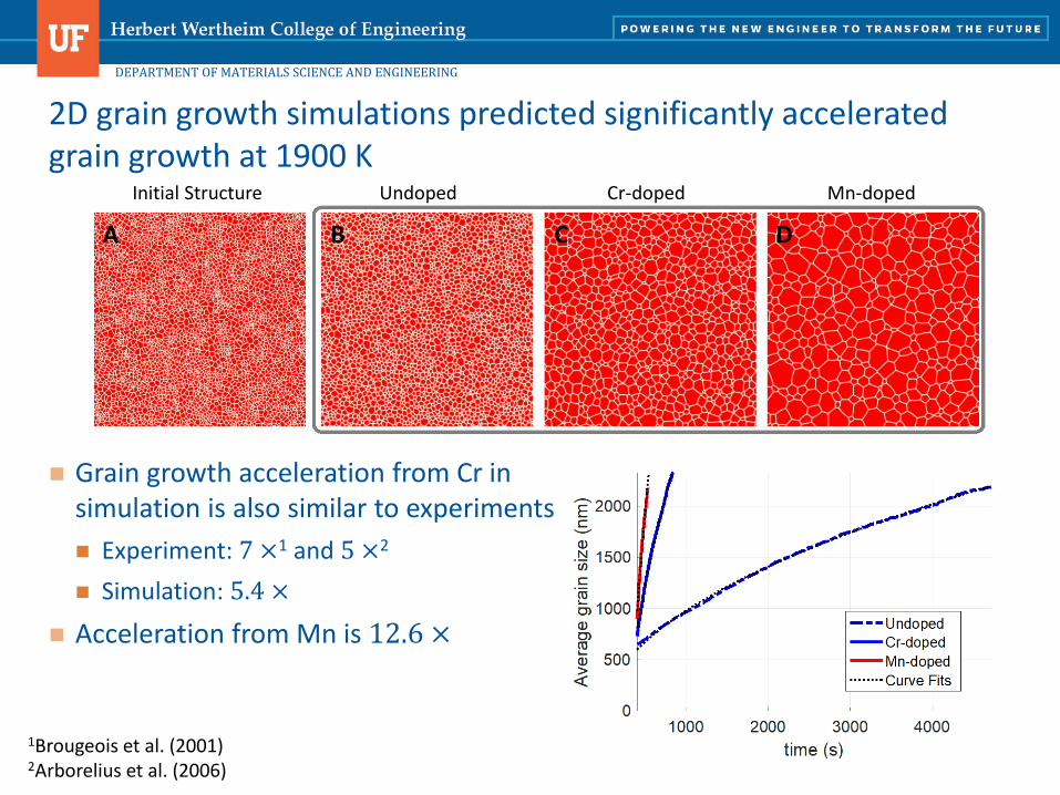
Grain growth acceleration from Cr in simulation is also similar to experiments Experiment: 7 ×1 and 5 ×2
Simulation: 5.4 × Acceleration from Mn is 12.6 ×
2D grain growth simulations predicted significantly accelerated grain growth at 1900 K
Initial Structure Undoped Cr-doped Mn-doped
1Brougeois et al. (2001) 2Arborelius et al. (2006)
DEPARTMENT OF MATERIALS SCIENCE AND ENGINEERING
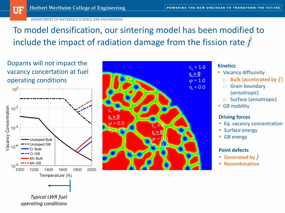
To model densification, our sintering model has been modified to include the impact of radiation damage from the fission rate 𝑓𝑓
Driving forces Eq. vacancy concentration Surface energy GB energy
Point defects Generated by ��𝒇 Recombination
Kinetics Vacancy diffusivity□ Bulk (accelerated by ��𝒇)□ Grain boundary
(anisotropic)□ Surface (anisotropic)
GB mobility
cv = 1.0ci = 0𝜑𝜑 = 1.0ηi = 0.0
cv > 0ci > 0𝜑𝜑 = 0.0η3 = 1.0
cv > 0ci > 0𝜑𝜑 = 0.0η1 = 1.0
Typical LWR fuel operating conditions
Dopants will not impact the vacancy concertation at fuel operating conditions
Cr-coated Zircaloy (Zr4, M5, Zirlo) Cladding
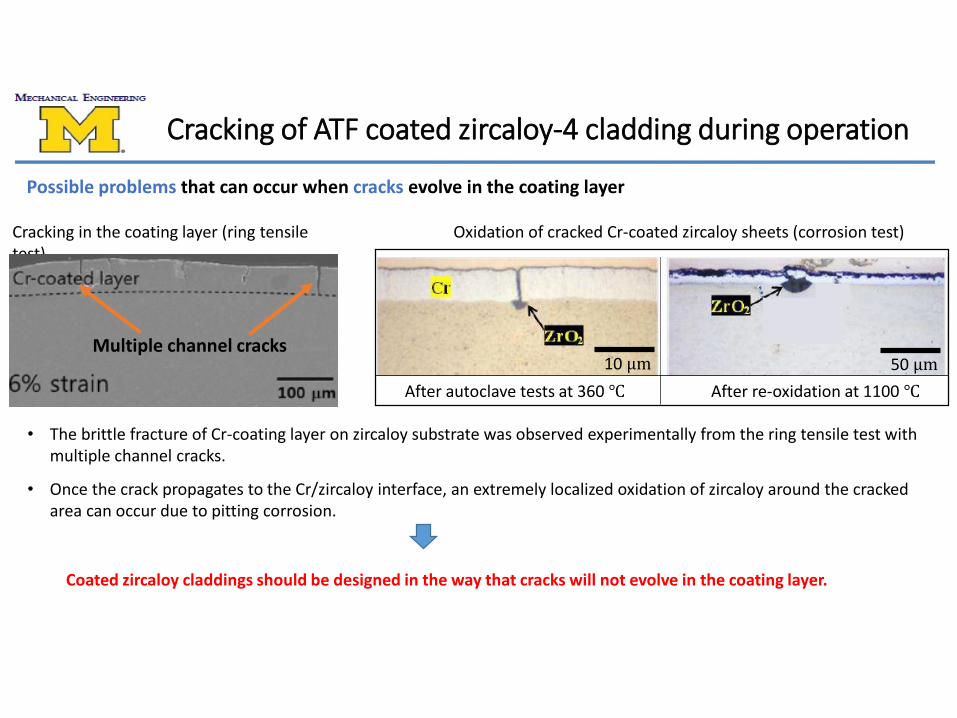
Oxidation of cracked Cr-coated zircaloy sheets (corrosion test)Cracking in the coating layer (ring tensile test)
• The brittle fracture of Cr-coating layer on zircaloy substrate was observed experimentally from the ring tensile test with multiple channel cracks.
• Once the crack propagates to the Cr/zircaloy interface, an extremely localized oxidation of zircaloy around the cracked area can occur due to pitting corrosion.
Cracking of ATF coated zircaloy-4 cladding during operation
Possible problems that can occur when cracks evolve in the coating layer
After autoclave tests at 360 ℃ After re-oxidation at 1100 ℃
Multiple channel cracks10 µm 50 µm
Coated zircaloy claddings should be designed in the way that cracks will not evolve in the coating layer.
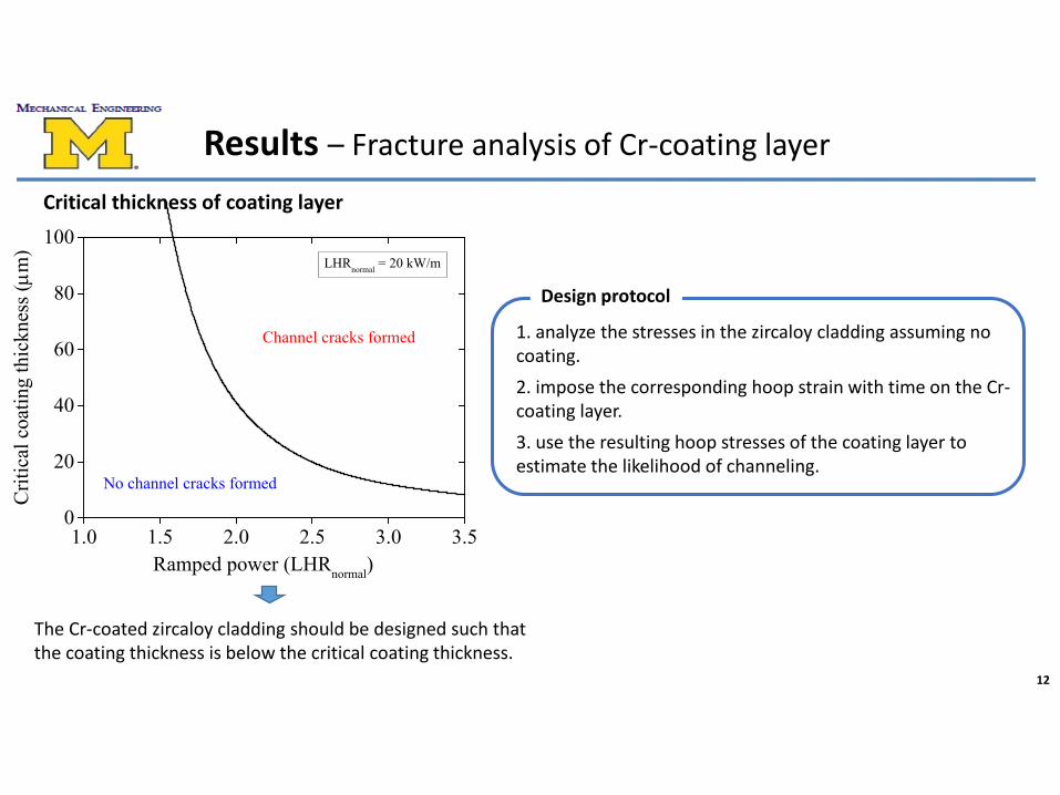
1.0 1.5 2.0 2.5 3.0 3.50
20
40
60
80
100LHRnormal = 20 kW/m
No channel cracks formed
Crit
ical
coa
ting
thic
knes
s (µm
)
Ramped power (LHRnormal)
Channel cracks formed
12
Results – Fracture analysis of Cr-coating layer
Critical thickness of coating layer
The Cr-coated zircaloy cladding should be designed such that the coating thickness is below the critical coating thickness.
1. analyze the stresses in the zircaloy cladding assuming no coating.2. impose the corresponding hoop strain with time on the Cr-coating layer.3. use the resulting hoop stresses of the coating layer to estimate the likelihood of channeling.
Design protocol

FeCrAl Cladding
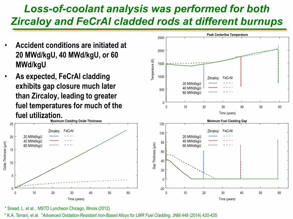
Loss-of-coolant analysis was performed for both Zircaloy and FeCrAl cladded rods at different burnups
• Accident conditions are initiated at 20 MWd/kgU, 40 MWd/kgU, or 60 MWd/kgU
• As expected, FeCrAl cladding exhibits gap closure much later than Zircaloy, leading to greater fuel temperatures for much of the fuel utilization.
* K.A. Terrani, et al. "Advanced Oxidation-Resistant Iron-Based Alloys for LWR Fuel Cladding, JNM 448 (2014) 420-435* Snead, L. et al., MSTD Luncheon Chicago, Illinois (2012)
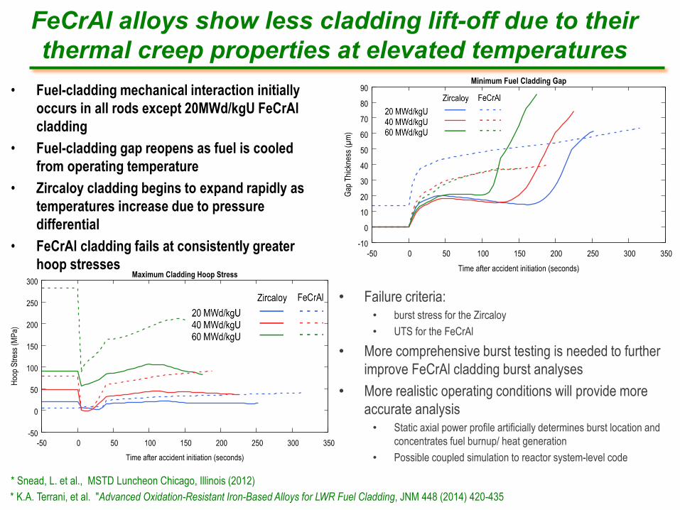
FeCrAl alloys show less cladding lift-off due to their thermal creep properties at elevated temperatures
* K.A. Terrani, et al. "Advanced Oxidation-Resistant Iron-Based Alloys for LWR Fuel Cladding, JNM 448 (2014) 420-435* Snead, L. et al., MSTD Luncheon Chicago, Illinois (2012)
• Fuel-cladding mechanical interaction initially occurs in all rods except 20MWd/kgU FeCrAl cladding
• Fuel-cladding gap reopens as fuel is cooled from operating temperature
• Zircaloy cladding begins to expand rapidly as temperatures increase due to pressure differential
• FeCrAl cladding fails at consistently greater hoop stresses
• Failure criteria:• burst stress for the Zircaloy• UTS for the FeCrAl
• More comprehensive burst testing is needed to further improve FeCrAl cladding burst analyses
• More realistic operating conditions will provide more accurate analysis
• Static axial power profile artificially determines burst location and concentrates fuel burnup/ heat generation
• Possible coupled simulation to reactor system-level code
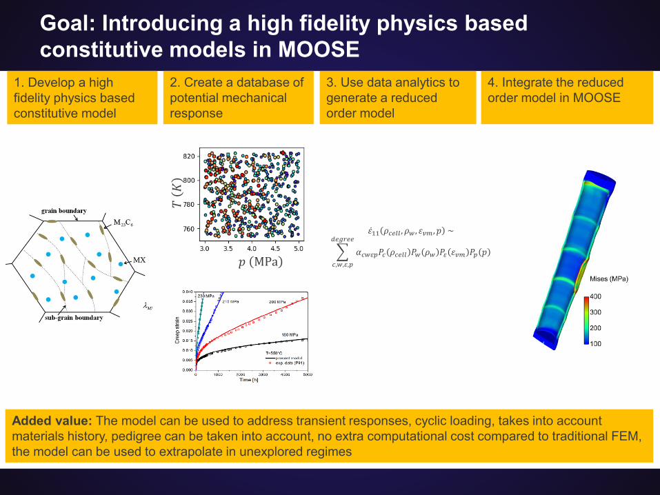
Goal: Introducing a high fidelity physics based constitutive models in MOOSE
𝜀𝜀11 𝜌𝜌𝑐𝑐𝑐𝑐𝑐𝑐𝑐𝑐 ,𝜌𝜌𝑤𝑤, 𝜀𝜀𝑣𝑣𝑣𝑣,𝑝𝑝 ~
�𝑐𝑐,𝑤𝑤,𝜀𝜀,𝑝𝑝
𝑑𝑑𝑐𝑐𝑑𝑑𝑑𝑑𝑐𝑐𝑐𝑐
𝛼𝛼𝑐𝑐𝑤𝑤𝜀𝜀𝑝𝑝𝑃𝑃𝑐𝑐 𝜌𝜌𝑐𝑐𝑐𝑐𝑐𝑐𝑐𝑐 𝑃𝑃𝑤𝑤 𝜌𝜌𝑤𝑤 𝑃𝑃𝜀𝜀 𝜀𝜀𝑣𝑣𝑣𝑣 𝑃𝑃𝑝𝑝 𝑝𝑝
1. Develop a high fidelity physics based constitutive model
2. Create a database of potential mechanical response
3. Use data analytics to generate a reduced order model
4. Integrate the reduced order model in MOOSE
𝑝𝑝 MPa
𝑇𝑇𝐾𝐾
Added value: The model can be used to address transient responses, cyclic loading, takes into account materials history, pedigree can be taken into account, no extra computational cost compared to traditional FEM, the model can be used to extrapolate in unexplored regimes
Demonstration
4/24/2019 | 24Los Alamos National Laboratory
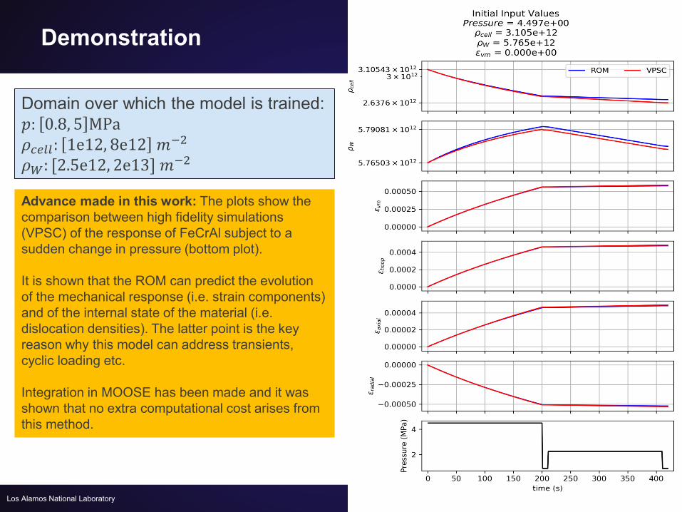
Domain over which the model is trained:𝑝𝑝: 0.8, 5 MPa𝜌𝜌𝑐𝑐𝑐𝑐𝑐𝑐𝑐𝑐: 1e12, 8e12 𝑚𝑚−2
𝜌𝜌𝑊𝑊: [2.5e12, 2e13] 𝑚𝑚−2
Advance made in this work: The plots show the comparison between high fidelity simulations (VPSC) of the response of FeCrAl subject to a sudden change in pressure (bottom plot).
It is shown that the ROM can predict the evolution of the mechanical response (i.e. strain components) and of the internal state of the material (i.e. dislocation densities). The latter point is the key reason why this model can address transients, cyclic loading etc.
Integration in MOOSE has been made and it was shown that no extra computational cost arises from this method.
U3Si2 Fuel
26
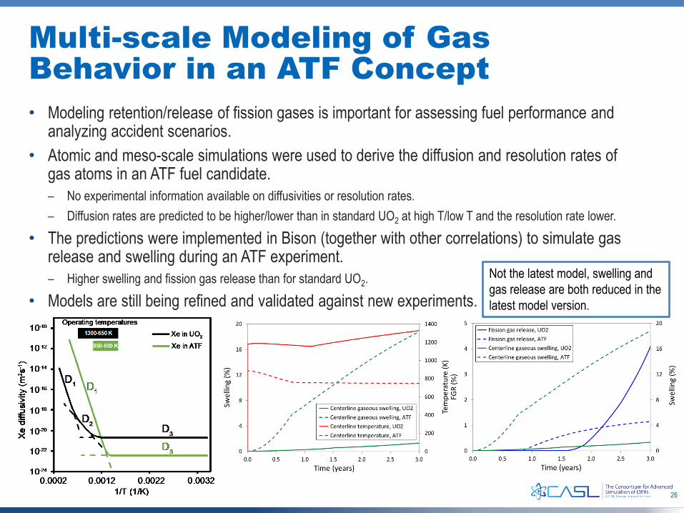
Multi-scale Modeling of Gas Behavior in an ATF Concept• Modeling retention/release of fission gases is important for assessing fuel performance and
analyzing accident scenarios.• Atomic and meso-scale simulations were used to derive the diffusion and resolution rates of
gas atoms in an ATF fuel candidate. – No experimental information available on diffusivities or resolution rates.– Diffusion rates are predicted to be higher/lower than in standard UO2 at high T/low T and the resolution rate lower.
• The predictions were implemented in Bison (together with other correlations) to simulate gas release and swelling during an ATF experiment.– Higher swelling and fission gas release than for standard UO2.
• Models are still being refined and validated against new experiments.Not the latest model, swelling and gas release are both reduced in the latest model version.
27
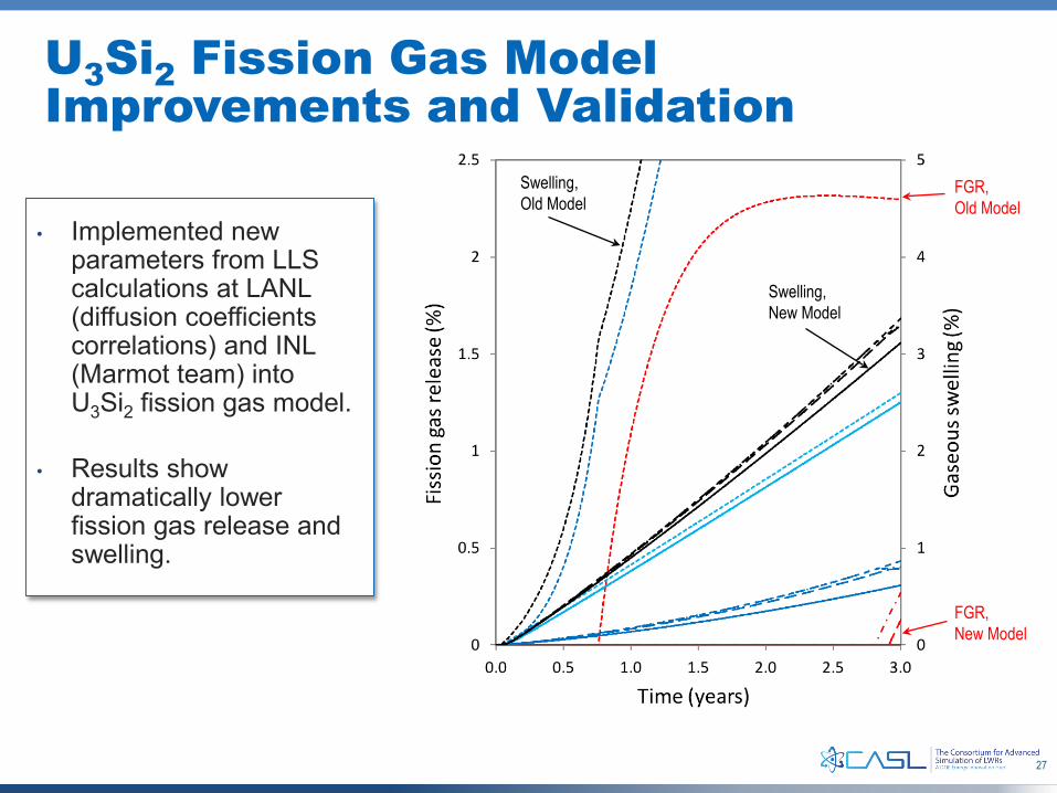
U3Si2 Fission Gas Model Improvements and Validation
• Implemented new parameters from LLS calculations at LANL (diffusion coefficients correlations) and INL (Marmot team) into U3Si2 fission gas model.
• Results show dramatically lower fission gas release and swelling.
FGR,Old Model
FGR,New Model
Swelling,Old Model
Swelling,New Model
29
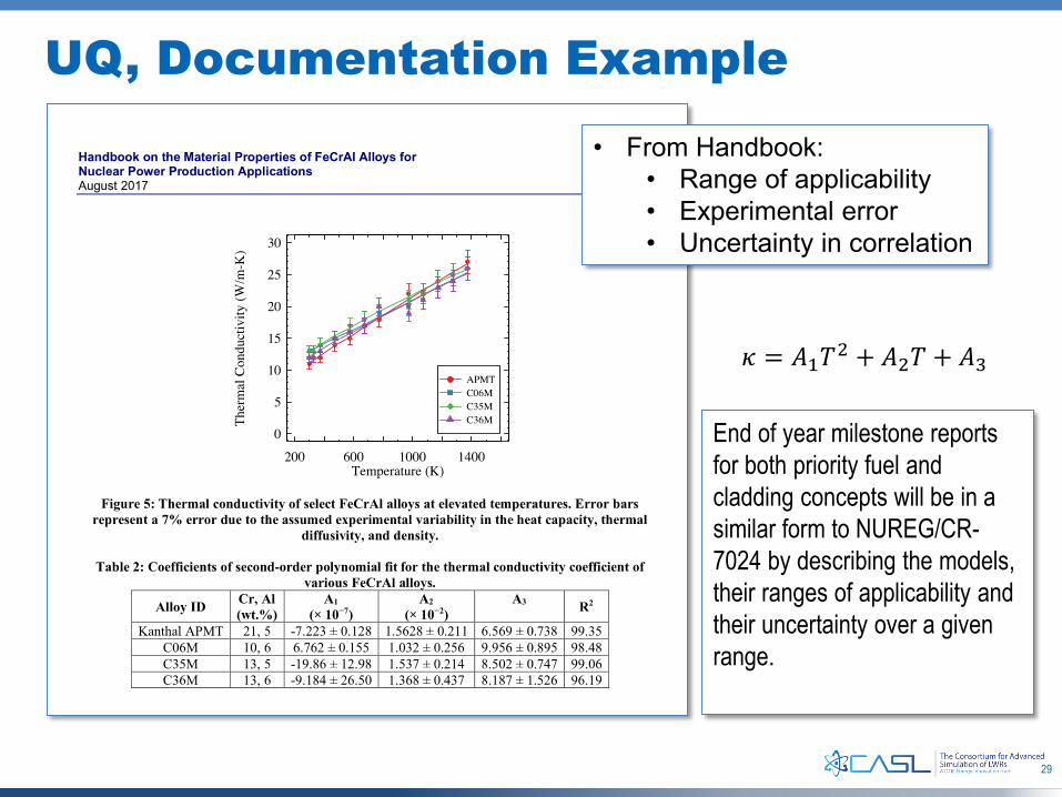
UQ, Documentation Example
𝜅𝜅 = 𝐴𝐴1𝑇𝑇2 + 𝐴𝐴2𝑇𝑇 + 𝐴𝐴3
• From Handbook:• Range of applicability• Experimental error• Uncertainty in correlation
End of year milestone reports for both priority fuel and cladding concepts will be in a similar form to NUREG/CR-7024 by describing the models, their ranges of applicability and their uncertainty over a given range.
30
Summary of ATF Work
• We are working to incorporate NRC’s and industry’s preferences and feedback into our model development
• Initial set of engineering-scale models are nearly in place– Lower length scale improvements will continue
• Beginning to transition to UQ and documentation tasks• On track to deliver reports on ATF models of both fuel and
cladding
Bison-TRACE Coupling Russell Gardner, BisonCody Permann, MOOSE Matt Bernard, NRC
energy.gov/ne32
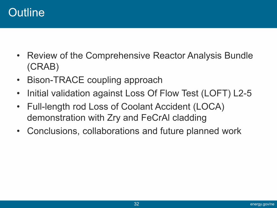
• Review of the Comprehensive Reactor Analysis Bundle (CRAB)
• Bison-TRACE coupling approach• Initial validation against Loss Of Flow Test (LOFT) L2-5• Full-length rod Loss of Coolant Accident (LOCA)
demonstration with Zry and FeCrAl cladding • Conclusions, collaborations and future planned work
Outline
energy.gov/ne33
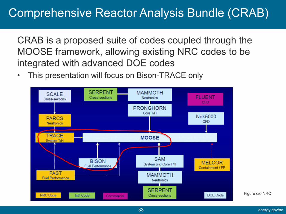
CRAB is a proposed suite of codes coupled through the MOOSE framework, allowing existing NRC codes to be integrated with advanced DOE codes• This presentation will focus on Bison-TRACE only
Comprehensive Reactor Analysis Bundle (CRAB)
Figure c/o NRC
energy.gov/ne34
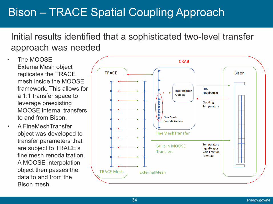
Bison – TRACE Spatial Coupling Approach
Initial results identified that a sophisticated two-level transfer approach was needed
• The MOOSE ExternalMesh object replicates the TRACE mesh inside the MOOSE framework. This allows for a 1:1 transfer space to leverage preexisting MOOSE internal transfers to and from Bison.
• A FineMeshTransferobject was developed to transfer parameters that are subject to TRACE’s fine mesh renodalization. A MOOSE interpolation object then passes the data to and from the Bison mesh.
energy.gov/ne35
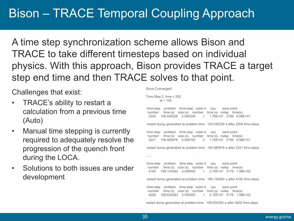
Bison – TRACE Temporal Coupling Approach
A time step synchronization scheme allows Bison and TRACE to take different timesteps based on individual physics. With this approach, Bison provides TRACE a target step end time and then TRACE solves to that point. Challenges that exist:• TRACE’s ability to restart a
calculation from a previous time (Auto)
• Manual time stepping is currently required to adequately resolve the progression of the quench front during the LOCA.
• Solutions to both issues are under development
Solve Converged!
Time Step 2, time = 200dt = 100
time-step problem time-step outer-it. cpu save pointnumber time (s) size (s) number time (s) nstep time(s)2204 100.040228 0.040228 1 1.70E+01 2199 9.98E+01
restart dump generated at problem time 100.040228 s after 2204 time steps
time-step problem time-step outer-it. cpu save pointnumber time (s) size (s) number time (s) nstep time(s)2221 100.585976 0.046102 2 1.70E+01 2199 9.98E+01
restart dump generated at problem time 100.585976 s after 2221 time steps
....
time-step problem time-step outer-it. cpu save pointnumber time (s) size (s) number time (s) nstep time(s)4192 199.134383 0.050000 1 2.10E+01 4178 1.98E+02
restart dump generated at problem time 199.134383 s after 4192 time steps
time-step problem time-step outer-it. cpu save pointnumber time (s) size (s) number time (s) nstep time(s)4202 199.634383 0.050000 1 2.10E+01 4178 1.98E+02
restart dump generated at problem time 199.634383 s after 4202 time steps
energy.gov/ne36
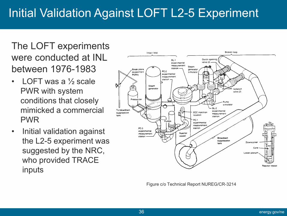
Initial Validation Against LOFT L2-5 Experiment
The LOFT experiments were conducted at INL between 1976-1983• LOFT was a ½ scale
PWR with system conditions that closely mimicked a commercial PWR
• Initial validation against the L2-5 experiment was suggested by the NRC, who provided TRACE inputs
Figure c/o Technical Report NUREG/CR-3214
energy.gov/ne37
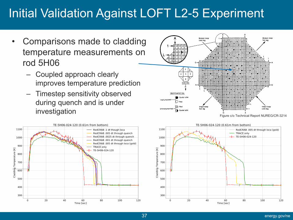
Initial Validation Against LOFT L2-5 Experiment
• Comparisons made to cladding temperature measurements on rod 5H06– Coupled approach clearly
improves temperature prediction– Timestep sensitivity observed
during quench and is under investigation
Figure c/o Technical Report NUREG/CR-3214
energy.gov/ne38
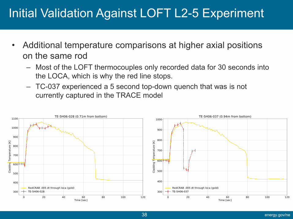
Initial Validation Against LOFT L2-5 Experiment
• Additional temperature comparisons at higher axial positions on the same rod– Most of the LOFT thermocouples only recorded data for 30 seconds into
the LOCA, which is why the red line stops.– TC-037 experienced a 5 second top-down quench that was is not
currently captured in the TRACE model
energy.gov/ne39
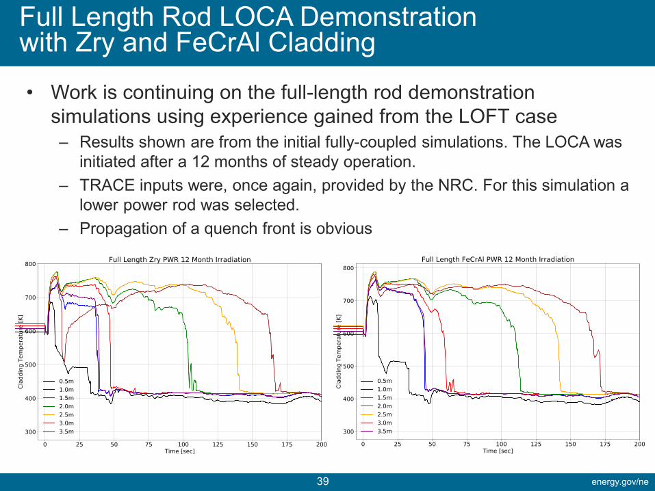
Full Length Rod LOCA Demonstration with Zry and FeCrAl Cladding
• Work is continuing on the full-length rod demonstration simulations using experience gained from the LOFT case– Results shown are from the initial fully-coupled simulations. The LOCA was
initiated after a 12 months of steady operation.– TRACE inputs were, once again, provided by the NRC. For this simulation a
lower power rod was selected.– Propagation of a quench front is obvious
energy.gov/ne40
Conclusions, Collaborations and Future Work
• Conclusions– Coupled Bison-TRACE capability has been established and represents an initial
demonstration of NRC’s CRAB concept– The codes can be run stand alone or in either a one-way or fully-coupled manner– An initial validation case (LOFT L2-5) has been completed, with the coupled codes
resulting in an improved prediction of cladding temperature– Coupling of Bison and TRACE combines the strengths of both codes, resulting in a
significantly improved simulation capability
• Collaboration– Very good working relationship has been established between the INL and NRC– Periodic site visits and cross training on codes is planned – Consulting on FAST-TRACE coupling.
• Future Work– Further investigation and simulation with the full-length rods– While the MOOSE framework can handle a variety of subcycling solves with failure,
further development is needed to fully support TRACE’s Auto stepping capability – A parameter has been identified to gage coupled solution convergence. Development
is underway to make this TRACE parameter available to MOOSE, allowing for tighter coupling and removing the need for user imposed, very small, timesteps
energy.gov/ne41
Questions?
![Refinement trees: Calculi, Tools and Applications€¦ · Language for CASL", WADT 2004 [CASL-Ref] IP. Ho man - \Architectural Speci cation Calculus", Chapter IV.5 of CASL Reference](https://img.pdfslide.us/doc/110x75/5feb7004e6531d35071d31a6/refinement-trees-calculi-tools-and-applications-language-for-casl-wadt.jpg)