Embed Size (px)
Citation preview

INTELLIBUS
Number : NR 1157
Revision : B
Page 1/19
INSTRUCTIONS FOR START-UP
Instructions for start-up
INTELLIBUS FF
FOUNDATION FIELDBUS FOR INTELLI+ (Intelli+ 2801)

INTELLIBUS
Number : NR 1157
Revision : B
Page 2/19
Instructions for start-up
SUMMARY
1 INTRODUCTION 3
2 TECHNICAL SPECIFICATIONS 3
3 FOUNDATION FIELDBUS INTERFACE 4
3.1 Hardware description 4
3.2 Cable type 5
3.3 Fieldbus connection 5
3.4 Set-up 5
3.5 Display indication of fieldbus communication status 6
3.6 Emergency supply 6
4 FUNDATIONAL FIELDBUS TECHNICAL OVERVIEW 6
4.1 Foundation Fieldbus communication 6 4.1.1 Link Active Scheduler 6 4.1.2 Function Block 7 4.1.3 Transducer Block 7 4.1.4 Device description 7
4.2 Foundation Fieldbus technology 7 4.2.1 Fieldbus Signaling 7 4.2.2 Maximum cable length 7 4.2.3 Terminator 8 4.2.4 Number of devices possible on the fieldbus 9 4.2.5 Repeaters 9
5 CONTROLS AND INDICATIONS 9
5.1 Actuator Controls 9
5.2 Actuator feedback indication 12
6 TRANSDUCER BLOCK 16
7 FUNCTION BLOCK PID 19

INTELLIBUS
Number : NR 1157
Revision : B
Page 3/19
Instructions for start-up
1 INTRODUCTION Foundation Fieldbus is an industrial fieldbus which allows connecting actuators and other devices (sensors …) to a Distributed Control System (DCS) or a Programmable Logic Controller (PLC). Many actuators and other devices can be connected on a fieldbus line provided they are all equipped with a compatible Foundation Fieldbus interface. Foundation Fieldbus uses standard Function Blocks. A Function Block could be digital output (DO) as commands open close, digital input (DI) as feedback status valve open, valve closed. There is also Function Blocks analog output (AO) and analog input (AI) for signals as position signals. A Proportionnal / Integral / Derivative (PID) control may be performed by the field through the use of Function Blocks. The Foundation Fieldbus interface described in this document has been specially designed for the Bernard actuators with INTELLI+ control. Control box with inside Foundation Fieldbus interface could be supplied to connect other equipment. Please make sure to get and read the INTELLI+ instructions for start-up (ref.NR1151) prior going further with the setting of the INTELLIBUS FF interface.
2 TECHNICAL SPECIFICATIONS
- The INTELLIBUS FF interface is powered directly from the fieldbus and is fully isolated from the actuator.
- Supply voltage (from the Fieldbus) 9 to 32V - Consumption 20mA - The INTELLIBUS FF interface is a Link Master device and is capable of
becoming a Link Active Scheduler (LAS) - CE Conformity. - The INTELLIBUS FF interface has successfully completed rigorous testing by
the Fieldbus Foundation and has received registration. - Device Description files available on request and on the web site
www.fieldbus.org - A loss of actuator power supply does not lead to a fieldbus disruption. - Temperature working range is the same as the actuator one.
INTELLIBUS
Number : NR 1157
Revision : B
Page 4/19
Instructions for start-up
3 FOUNDATION FIELDBUS INTERFACE
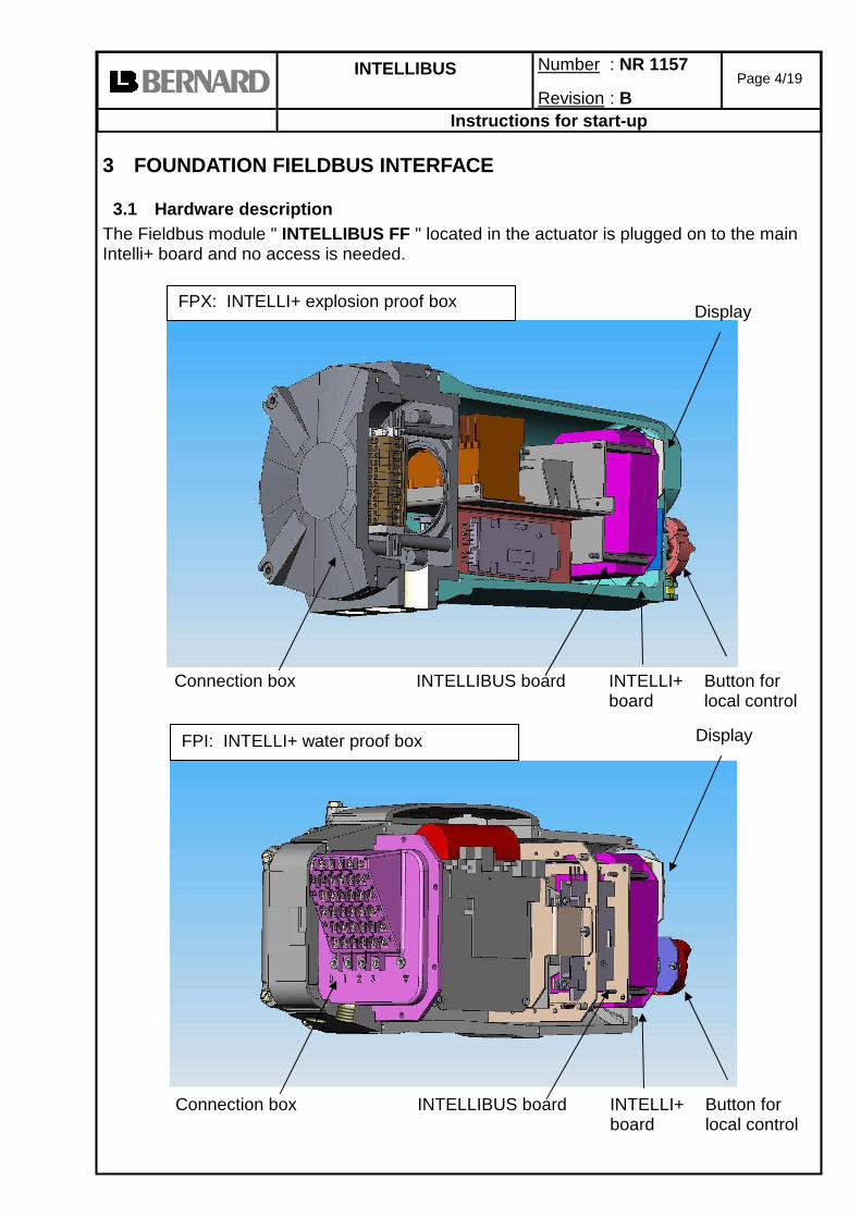
3.1 Hardware description The Fieldbus module " INTELLIBUS FF " located in the actuator is plugged on to the main Intelli+ board and no access is needed.
Connection box INTELLI+
board Button for local control
Display
INTELLIBUS board
FPX: INTELLI+ explosion proof box
Connection box INTELLI+
board Button for local control
Display
INTELLIBUS board
FPI: INTELLI+ water proof box

INTELLIBUS
Number : NR 1157
Revision : B
Page 5/19
Instructions for start-up
3.2 Cable type The cable must be specify for Foundation Fieldbus type A For example: Belden 3076F) 1 pair 18 AWG Resistance 5.86 ohms/1000ft @20°C Nominal mutual capacitance @ 1kHz: 80pF/m (24pF/ft) Type shield: shielding braid or foil Fieldbus cable has to be separated from the other cables with a distance of at least 20cm. It will use a specific cable path and be connected to the earth. It is also necessary to check that all actuators are at the same earth electrical potential.
3.3 Fieldbus connection Junction box terminals 35-36: Shield: Cable shielding End of line termination A termination has to be installed at each end of line. This termination is not built in the actuator.
3.4 Set-up The INTELLIBUS module is selected in the menu: Use the local control button of the actuator. (refer: NR1151). In the menu select Change then select Fieldbus then select Card FF present and choose (yes) Confirm OK with the red button. To save, select return in each submenu until to read: RETURN (Change OK?) Confirm OK with the red button. When the Fieldbus card is selected then the menu shows the other configurations: Lost communication: In case of loss of communication the actuator operates to the close position, open position or stays in position.
35
Shield
34 36
Previous actuator
Next actuator
The connection depends of actuator type. Refer to the actuator wiring diagram
actuator

INTELLIBUS
Number : NR 1157
Revision : B
Page 6/19
Instructions for start-up
The default setting is stayput. Also in case of loss of communication all controls are reset. For example if the auxiliary control AUX1 is configured "Local control inhibit" when communication is lost, local controls are available again. Cmd by fieldbus: The default setting is Yes. If No is selected then no command is taken into account through the fieldbus. Only indications are transmitted.
3.5 Display indication of fieldbus communication status An indication of the fieldbus communication status is available on the actuator display.
No data exchange (empty square)
Data exchange (rotating triangle)
Intellibus module fault (blinking cross)
3.6 Emergency supply The actuator Intelli+ is normally supplied by the mains but in case of loss of power supply an emergency supply could be used to continue to communicate through the fieldbus. This emergency supply needs 24V DC 4W. The optional extra battery is also an alternative to be able to read the display during power off period but also to update the position in case of a change. The right position is then updated through the fieldbus communication.
4 FUNDATIONAL FIELDBUS TECHNICAL OVERVIEW
4.1 Foundation Fieldbus communication
4.1.1 Link Active Scheduler The INTELLIBUS FF interface, can communicate with Distributed Control System (DCS), Programming Logic Controller (PLC), Personnal Computer (PC), or other devices from various suppliers equipped with Foundation Fieldbus. Communication on the Fieldbus is managed by a Link Active Scheduler (LAS). The LAS has a list of the devices connected and sends cyclic messages to all devices. The LAS sends also a Pass Token message that allows an actuator to transmit unscheduled messages Any Link Master device may becoming a LAS The Fieldbus may have multiple Link Masters. If the current LAS fails, one of the Link Masters will become the LAS and the operation fieldbus will continue. The actuator with INTELLIBUS FF could be a LAS. Actuator address: There is no address configuration to the actuator level. This is performed automatically by the Link Active Scheduler (LAS). New actuators may be added to the fieldbus at any time. The LAS periodically sends Probe Node (PN) messages to the addresses not in the live list. If an actuator is present at the addresses and receives the PN, immediately returns a Probe Response message. If
BUS
BUS
BUS

INTELLIBUS
Number : NR 1157
Revision : B
Page 7/19
Instructions for start-up
the actuator answers with a PR, the LAS adds the actuator to the live list and confirms its addition by sending the actuator a Node Activation message.
4.1.2 Function Block A function block is like a black box inside the INTELLIBUS FF interface with input and output parameters. Function Block is used by the control system to communicate through the Fieldbus. Function block name: Discrete input (DI) (input in a fieldbus view) For example: valve is open Discrete output (DO) For example: close the valve Analog input (AI) For example: valve is 50% open Analog output (AO) For example: close the valve at 30% In each function block there is a list of parameters available (see § 4) An other Function Block is the Proportional/ Integral / Derivative (PID) to perform control loop (see § 6).
4.1.3 Transducer Block The Transducer Block contains information not used for the process such as manufacture date, dead band setting, opening and closing torque/position curve. (see §5 )
4.1.4 Device description To achieve interoperability Device Description (DD) technology is used. The DD is like a “driver” for a printer. L.Bernard supply the Device Description for the INTELLIBUS FF interface.
4.2 Foundation Fieldbus technology
4.2.1 Fieldbus Signaling The transmitting device delivers +/- 10mA at 31.25 kbit/s into a 50 ohm equivalent load to create a 1.0 volt peak-to-peak voltage modulated on top of the direct current supply voltage. The DC voltage can range from 9 to 32V. The maximum DC current available depends of the fieldbus power supply.
4.2.2 Maximum cable length The Fieldbus cable coming from a PLC is connected to the first actuator then the Fieldbus cable links this actuator with the next one and so on. All actuators are connected to the line one after the other until the last one. No return to the PLC is required. The 31.25kbit/s fieldbus allows ramifications or “spurs” but with restrictions Cable length = Trunk length + total spur lengths Maximum length = 1900m (6200ft) with “Type A” cable
Devices Max total spur length 25-32 No spur No spur 19-24 30m 100ft 15-18 60m 200ft 13-14 90m 300ft 1-12 120m 400ft
voltage
time
Fieldbus messages
INTELLIBUS
Number : NR 1157
Revision : B
Page 8/19
Instructions for start-up
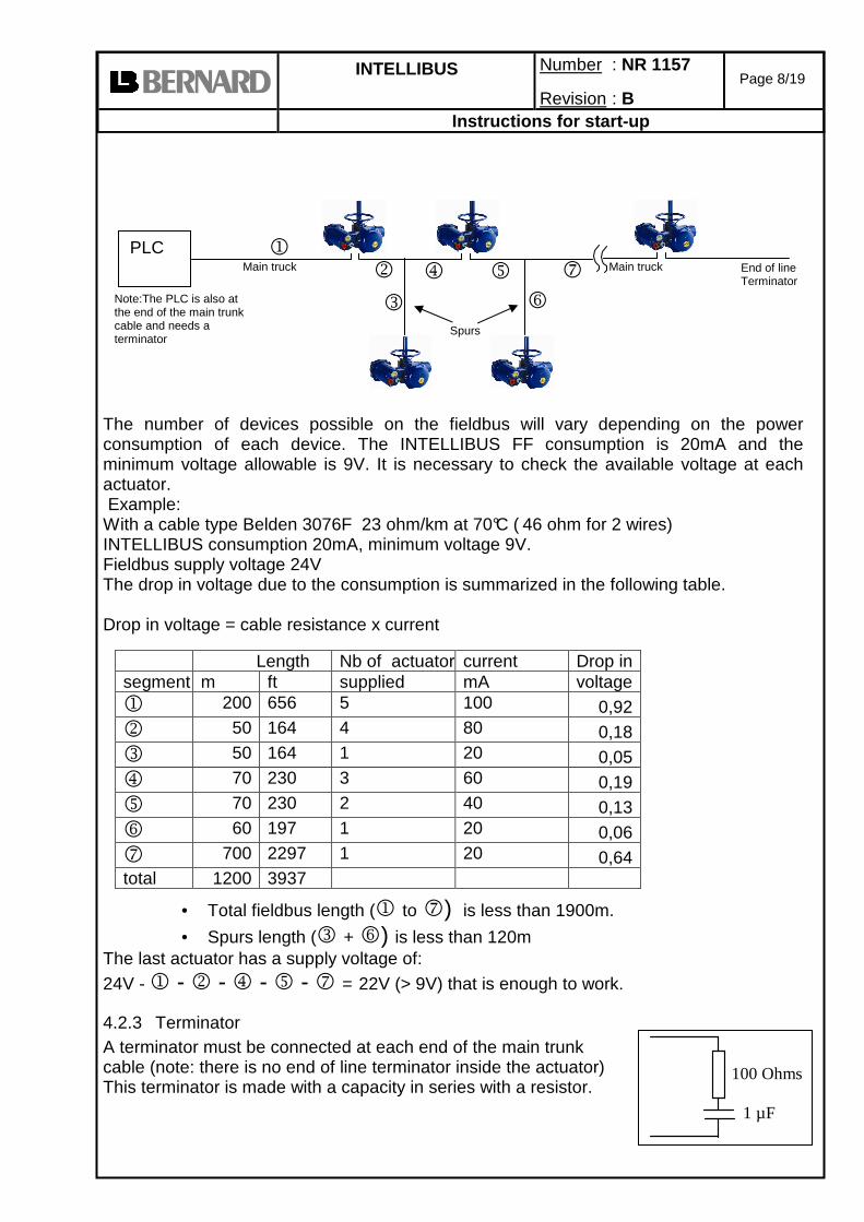
The number of devices possible on the fieldbus will vary depending on the power consumption of each device. The INTELLIBUS FF consumption is 20mA and the minimum voltage allowable is 9V. It is necessary to check the available voltage at each actuator. Example: With a cable type Belden 3076F 23 ohm/km at 70°C ( 46 ohm for 2 wires) INTELLIBUS consumption 20mA, minimum voltage 9V. Fieldbus supply voltage 24V The drop in voltage due to the consumption is summarized in the following table. Drop in voltage = cable resistance x current
• Total fieldbus length (1 to 7) is less than 1900m.
• Spurs length (3 + 6) is less than 120m The last actuator has a supply voltage of:
24V - 1 - 2 - 4 - 5 - 7 = 22V (> 9V) that is enough to work.
4.2.3 Terminator A terminator must be connected at each end of the main trunk cable (note: there is no end of line terminator inside the actuator) This terminator is made with a capacity in series with a resistor.
Length Nb of actuatorscurrent Drop in segment m ft supplied mA voltage 1 200 656 5 100 0,92 2 50 164 4 80 0,18 3 50 164 1 20 0,05 4 70 230 3 60 0,19 5 70 230 2 40 0,13 6 60 197 1 20 0,06 7 700 2297 1 20 0,64 total 1200 3937
PLC
Spurs
End of line Terminator
Note:The PLC is also at the end of the main trunk cable and needs a terminator
1 2
3
4 5
6
7
100 Ohms
1 µF
Main truck Main truck

INTELLIBUS
Number : NR 1157
Revision : B
Page 9/19
Instructions for start-up
Remark : If a Function Block is only one bit writable, then use DO(1), DO(2),DO(3) to reach the controls Open, Close and Stop. In other case Function Block DO(1) is sufficient for controls Open, Close and Stop
4.2.4 Number of devices possible on the fieldbus The number of devices depends of the power supply of the fieldbus. With a supply of 24V 350mA it is possible to connect until 17 actuators (each actuator needs 20mA)
4.2.5 Repeaters Adding repeaters modules allows to increase both the number of actuator on the line and total line length. Each repeater allows to lengthen the line by 1900m. See §4.2.2 to know the possible device number and maximum length for each segment. According to the type of repeater, it is possible to use until 4 repeaters. Take also into account the repeater consumption on the fieldbus (usually 30mA). The important advantage of the repeater compared to other repeater-free technologies is to keep the communication speed unaffected and therefore to get a very short response time. L. Bernard can supply weatherproof or explosion proof repeaters.
5 CONTROLS AND INDICATIONS With Foundation Fieldbus system, controls and indications are organized in Function Blocks. For actuator controls (§4.1) there is Function Block Discrete Output (DO) or Analog Output (AO). Output is a Fieldbus view: output of the Fieldbus. For actuator indications (§4.2) there is Function Block Discrete Input (DI) or Analog Input (AI). These data are mainly use for the Process. For configuration, setting and maintenance the data are brought together in the Transducer Block (§5)
5.1 Actuator Controls Actuator control by Foundation Fieldbus is possible only if the actuator rotating selector is on the "remote" position. Conditions which can prevent a command to be executed:
- Actuator rotating selector on "local" or "OFF". - Alarm tripped (motor thermal overload) - Emergency command received (ESD)
Actuators controls are located at the Function Block Discrete Output (DO) in the INTELLIBUS module. These controls are:
PLC Repeater
Repeater power supply
Segment 1 Segment 2
End of line Terminator

INTELLIBUS
Number : NR 1157
Revision : B
Page 10/19
Instructions for start-up
Function Block DO(1) Bit n° Value Description Bit 0 0 No command 1 Close command Bit 1 0 No command 1 Open command Bit 2 0 Stop ( or maintained command mode) 1 No stop (or Pulse command mode) Bit 3 0 No command 1 Auxiliary command 1 Bit 4 0 No command 1 Auxiliary command 2 Bit 5 0 Relay 1 contact open 1 Relay 1 contact closed Bit 6 0 Relay 2 contact open 1 Relay 2 contact closed Bit 7 0 Relay 3 contact open 1 Relay 3 contact closed
OPEN / CLOSE: Open and close command. According to the actuator configuration, it is possible to select a priority to the opening or to the closing command (refer to NR1151) By default there is no priority given to either opening or closing. Priority can be used to: - Allow to reverse the actuator rotation direction during a manoeuvre without having to use the stop command. In this case it is necessary to set a priority to the opening or to the closing direction. - Give priority to one or the other rotation direction: if the actuator receives the open and close commands simultaneously and the priority has been given to the opening, the actuator will run the open position. STOP: if this command is maintained at 0 (most common case), the open and close commands have to be maintained. If this command is set to 1, a short duration open / close command pulse is sufficient to drive the valve to the open or closed position. In this case, the stop command (0) can be used to stop the actuator during the travel in its current position. AUXILIARY COMMANDS By default, auxiliary command 1 is assigned to local control (actuator selector) inhibited. By default, auxiliary command 2 is not assigned to a Fieldbus command but to an emergency command (ESD): This command is hardwired (separate wiring) and directly connected to the control box main strip. These commands depend of actuator configuration (refer to NR1151) and can be assigned to the following functions. LOCAL / REMOTE: substitutes for the local/remote selector of the actuator and is used to remotely enable either remote control or local control. LOCAL+REMOTE / REMOTE: same definition as above, but local and remote control can be enabled simultaneously. LOCAL COMMAND INHIBIT: the local command inhibit is remotely controlled. This command inhibits the local opening and closing commands, and enables remote commands, even if the local/remote selector of the actuator is set to local. OPEN, CLOSE INHIBIT: this command is used to inhibit opening or closing of the actuator. AUTO/ON-OFF: for an actuator used in modulation with positioner function, it is possible to issue remote commands via proportional control (equivalent to 4-20mA) or via

INTELLIBUS
Number : NR 1157
Revision : B
Page 11/19
Instructions for start-up
opening/closing/stop commands. The auto/on-off command is used to switch over from one type of command to another. ESD CLOSE, OPEN, STOP: the ESD (Emergency Shut Down) is an emergency remote command, which overrides all other commands. According to the valve operation, the emergency command will be an opening, closing or intermediate stop. This ESD command is assigned to a Fieldbus command for auxiliary command 1 and assigned to a hardwired (separate wiring) for auxiliary command 2. Note: The hardwired ESD has a higher priority than Fieldbus ESD. The emergency command is not possible when the local /remote selector is set to "OFF". PARTIAL STROKE. This command performs automatically a test to confirm that the actuator is still operational. The test consists to operate the actuator on a partial stroke and return. The start position and the stroke % can be configured. An alarm is emitted if the stroke is not performed in a predetermined delay. This delay is worked out from the rated operating time. RELAYS The relays could be used to have an output indication (wired as a non fieldbus actuator) or to drive outside devices through Fieldbus. These optional relays could be configured in Intelli+ menu for actuator indication or output controls. Function Block DO(2) The same controls are available in various Function Blocks Bit n° Value Description Bit 0 0 No command 1 Open command Bit 1 0 No command 1 Close command Bit 2 0 Stop ( or maintained command mode) 1 No stop (or Pulse command mode) Bit 3 0 No command 1 Auxiliary command 1 Bit 4 0 No command 1 Auxiliary command 2 Bit 5 0 Relay 1 contact open 1 Relay 1 contact closed Bit 6 0 Relay 2 contact open 1 Relay 2 contact closed Bit 7 0 Relay 3 contact open 1 Relay 3 contact closed
INTELLIBUS
Number : NR 1157
Revision : B
Page 12/19
Instructions for start-up
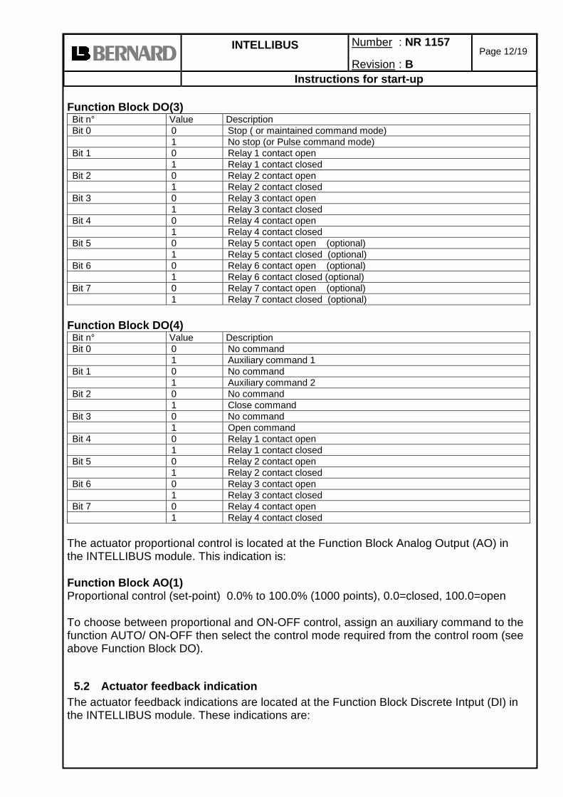
Function Block DO(3) Bit n° Value Description Bit 0 0 Stop ( or maintained command mode) 1 No stop (or Pulse command mode) Bit 1 0 Relay 1 contact open 1 Relay 1 contact closed Bit 2 0 Relay 2 contact open 1 Relay 2 contact closed Bit 3 0 Relay 3 contact open 1 Relay 3 contact closed Bit 4 0 Relay 4 contact open 1 Relay 4 contact closed Bit 5 0 Relay 5 contact open (optional) 1 Relay 5 contact closed (optional) Bit 6 0 Relay 6 contact open (optional) 1 Relay 6 contact closed (optional) Bit 7 0 Relay 7 contact open (optional) 1 Relay 7 contact closed (optional)
Function Block DO(4) Bit n° Value Description Bit 0 0 No command 1 Auxiliary command 1 Bit 1 0 No command 1 Auxiliary command 2 Bit 2 0 No command 1 Close command Bit 3 0 No command 1 Open command Bit 4 0 Relay 1 contact open 1 Relay 1 contact closed Bit 5 0 Relay 2 contact open 1 Relay 2 contact closed Bit 6 0 Relay 3 contact open 1 Relay 3 contact closed Bit 7 0 Relay 4 contact open 1 Relay 4 contact closed
The actuator proportional control is located at the Function Block Analog Output (AO) in the INTELLIBUS module. This indication is: Function Block AO(1) Proportional control (set-point) 0.0% to 100.0% (1000 points), 0.0=closed, 100.0=open To choose between proportional and ON-OFF control, assign an auxiliary command to the function AUTO/ ON-OFF then select the control mode required from the control room (see above Function Block DO).
5.2 Actuator feedback indication The actuator feedback indications are located at the Function Block Discrete Intput (DI) in the INTELLIBUS module. These indications are:

INTELLIBUS
Number : NR 1157
Revision : B
Page 13/19
Instructions for start-up
Function Block DI(1) Bit n° Value Description Bit 0 0 Valve not closed 1 Valve closed Bit 1 0 Valve not open 1 Valve Open Bit 2 0 The actuator is not running 1 Actuator running Bit 3 0 actuator not closing 1 Actuator closing Bit 4 0 actuator not opening 1 Actuator opening Bit 5 0 selector not to remote position 1 Selector to remote position Bit 6 0 selector not to OFF position 1 Selector to OFF position Bit 7 0 selector not to local position 1 Selector to local position
VALVE OPEN/CLOSE: confirms the valve is open or closed ACTUATOR RUNNING: the actuator is operated in opening or closing direction ACTUATOR OPENING/CLOSING: the actuator is operated in opening/closing direction SELECTOR TO REMOTE: No command allowed from Local controls. SELECTOR TO OFF: no command allowed in local or from Fieldbus. Indications are always available. SELECTOR TO LOCAL: No command allowed from Fieldbus. Indications are always available. Function Block DI(2) Bit n° Value Description Bit 0 0 Valve not open 1 Valve Open Bit 1 0 Valve not closed 1 Valve closed Bit 2 0 actuator not closing 1 Actuator closing Bit 3 0 actuator not opening 1 Actuator opening Bit 4 0 selector not to remote position 1 Selector to remote position Bit 5 0 Actuator available 1 Actuator fault indication Bit 6 0 no ESD command 1 Actuator receives an emergency command ESD Bit 7 0 No valve jammed alarm 1 Valve jammed
ACTUATOR FAULT INDICATION: The actuator is not available due to a following event: Motor thermal overload, lost phase (in case of 3ph supply), locked rotor. Including additional faults(refer to NR1151 to configure): Selected option: selector in local, selector in off. Options: jammed valve, emergency command, command inhibit, overtravel.
INTELLIBUS
Number : NR 1157
Revision : B
Page 14/19
Instructions for start-up
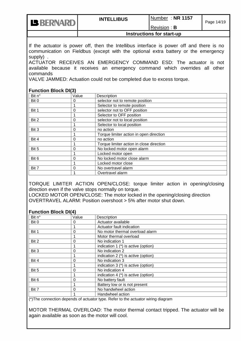
If the actuator is power off, then the Intellibus interface is power off and there is no communication on Fieldbus (except with the optional extra battery or the emergency supply) . ACTUATOR RECEIVES AN EMERGENCY COMMAND ESD: The actuator is not available because it receives an emergency command which overrides all other commands VALVE JAMMED: Actuation could not be completed due to excess torque. Function Block DI(3) Bit n° Value Description Bit 0 0 selector not to remote position 1 Selector to remote position Bit 1 0 selector not to OFF position 1 Selector to OFF position Bit 2 0 selector not to local position 1 Selector to local position Bit 3 0 no action 1 Torque limiter action in open direction Bit 4 0 no action 1 Torque limiter action in close direction Bit 5 0 No locked motor open alarm 1 Locked motor open Bit 6 0 No locked motor close alarm 1 Locked motor close Bit 7 0 No overtravel alarm 1 Overtravel alarm
TORQUE LIMITER ACTION OPEN/CLOSE: torque limiter action in opening/closing direction even if the valve stops normally on torque. LOCKED MOTOR OPEN/CLOSE: The motor locked in the opening/closing direction OVERTRAVEL ALARM: Position overshoot > 5% after motor shut down. Function Block DI(4) Bit n° Value Description Bit 0 0 Actuator available 1 Actuator fault indication Bit 1 0 No motor thermal overload alarm 1 Motor thermal overload Bit 2 0 No indication 1 1 indication 1 (*) is active (option) Bit 3 0 No indication 2 1 indication 2 (*) is active (option) Bit 4 0 No indication 3 1 indication 3 (*) is active (option) Bit 5 0 No indication 4 1 indication 4 (*) is active (option) Bit 6 0 No battery fault 1 Battery low or is not present Bit 7 0 No handwheel action 1 Handwheel action
(*)The connection depends of actuator type. Refer to the actuator wiring diagram MOTOR THERMAL OVERLOAD: The motor thermal contact tripped. The actuator will be again available as soon as the motor will cool.

INTELLIBUS
Number : NR 1157
Revision : B
Page 15/19
Instructions for start-up
INDICATION 1 to 4 IS ACTIVE (option): Indications of hardwired inputs (allows to communicate through Fieldbus, indications coming from outside devices). BATTERY LOW OR IS NOT PRESENT: In case of battery option the battery should be replaced because of too low voltage or the battery is missing. HANDWHEEL ACTION: the handwheel has been actuated since the last electrical operation Function Block DI(5) Bit n° Value Description Bit 0 0 The actuator is not running 1 Actuator running Bit 1 0 No stop mid travel 1 Stop mid travel Bit 2 0 Power off 1 Power on Bit 3 0 No lost phase alarm 1 Lost phase Bit 4 0 No lost signal 1 Lost signal Bit 5 0 No position sensor power supply fault 1 Position sensor power supply fault Bit 6 0 No torque sensor power supply fault 1 Torque sensor power supply fault Bit 7 0 No indication 5 1 indication 5 (*) is active (ESD input by default)
(*)The connection depends of actuator type. Refer to the actuator wiring diagram ACTUATOR RUNNING: the actuator is operated in opening or closing direction STOP MID TRAVEL: The actuator is at a stop, neither open nor closed. POWER ON: The actuator is normally powered. LOST PHASE: In 3 phase, a phase is missing. No start allowed. LOST SIGNAL: 4 to 20mA lost signal (In case of analogue and hardwired input signal) POSITION OR TORQUE POWER SUPPLY FAULT: Intelli+ receives no information from the position or torque sensor. INDICATION 5 IS ACTIVE: By default this terminal is assigned to a hardwired emergency command (ESD) and an ESD command is present. The actuator feedback position and torque are located at the Function Block Analog Intput (AI) in the INTELLIBUS module. These indications are: Function Block AI(1) Actuator position feedback: 0.0% to 100.0% (1000 points) ACTUATOR POSITION FEEDBACK: Actuator position in % of opening 0%= closed, 100%= open Function Block AI(2) Running torque 0 to 150% RUNNING TORQUE: Indication of the instantaneous torque. 100% is the maximum actuator rated torque

INTELLIBUS
Number : NR 1157
Revision : B
Page 16/19
Instructions for start-up
6 TRANSDUCER BLOCK
Available data through FIELDBUS in the Transducer Block N° Data Value Number
of bytes Type
1 Operating class 1: On - Off 2: Modulating Classe III 3 : Modulating Classe II
1 read only
2 Nut thread (If linear system)
In mm (To calculate the stroke but only during set-up). Value is zero if no linear system.
1 read only
3 Locked motor timing In seconds 1 read only
4 Motor supply type 0: 3 phase 1: single phase or DC
1 read only
5 Reverse delay time (unit 50ms) Ex. 3 = 150ms
1 read only
6 Closing mode 0: close on position 1: close on torque 3: open and close on torque
1 read only
7 Stroke unit 1: number of turns 2: degrees 3: mm
1 read only
8 Set-up for auxiliary command 1 () Bit state for active command (see 4.1)
0: not used 1:local(0)/remote(1) 2:local+remote(0) /remote(1) 3:local command inhibit(1) 4:open inhibit(1) 5:close inhibit(1) 6:On-off(0) / AUTO(1) 7:fieldbus emergency closing (1) 8: fieldbus emergency opening (1) 9: fieldbus emergency stop (1) 10: partial stroking (1)
1 read / write
9 Set-up for auxiliary command 2 coming through the fieldbus but for emergency commands wired separately from the fieldbus.
0: not used 1:local(0)/remote(1) 2:local+remote(0) /remote(1) 3:local command inhibit(1) 4:open inhibit(1) 5:close inhibit(1) 6:On-off(0) / AUTO(1) 7:wired emergency closing (1) 8: wired emergency opening (1) 9: wired emergency stop (1) 10: partial stroking (1)
1 read / write

INTELLIBUS
Number : NR 1157
Revision : B
Page 17/19
Instructions for start-up
10 Local stop also inhibited with a local command inhibit
0: no, local stop is possible 1: yes, local stop and off inhibited
1 read / write
11 Dead band for positioner function
Unit 0.1% mini value: 2 (0.2%) maxi value: 50 (5%)
1 read / write
12 Timing control 0: no timing control 1: timing control
1 read / write
13 Start of closing temporised zone
0 to100 % 1 read / write
14 End of closing temporised zone
0 to 100 % (lower than start value) 1 read / write
15 Start of opening temporised zone
0 to100 % 1 read / write
16 End of opening temporised zone
0 to 100 % (higher than start value) 1 read / write
17 Timer open time expected
in seconds 2 read / write
18 Timer close time expected
in seconds 2 read / write
19 Operating time without timer
in seconds 2 read / write
20 no local stop in remote mode
0= local stop possible 1= no local stop
1 read / write
21 Fail safe position in case of loss of communication
0= stayput 1= closing 2= opening
1 read / write
22 open priority 0= no priority 1= open priority
1 read / write
23 close priority 0= no priority 1= close priority
1 read / write
24 In case of emergency command, torque limit is 100%
0= no 1= yes
1 read / write
25 In case of emergency command, thermal overload is by- passed
0= no 1= yes
1 read / write
26 External gear ratio (format: 1/ ) ex 200 = 1/200
2 read only
27 Actuator number ASCII characters 16 read only
28 Manufacture date ASCII characters 12 read only
29 Software version ASCII characters ex:1.03 6 read only
30 Stroke measured during set-up
For stroke unit see address 7
2 read only
31 Opening torque curve Torque in % Data 1 = closed position Data 2= 1% open Data 101= 100% open
101 read only

INTELLIBUS
Number : NR 1157
Revision : B
Page 18/19
Instructions for start-up
32 Closing torque curve Torque in % Data 1 = closed position Data 2= 1% open Data 101= 100% open
101 read only
33 Open breakout max torque during the last electrical actuation
in % 1 read only
34 Close tight max torque during the last electrical actuation
in % 1 read only
35 Opening max torque during the last electrical actuation
in % 1 read only
36 Closing max torque during the last electrical actuation
in % 1 read only
37 Starts last 12 hours 2 read only
38 Total number of starts 4 read only
39 Total running time Unit is 1/10 sec 4 read only
40 Partial number of starts (since the last reset)
4 read only
41 Partial running time (since the last reset)
Unit is 1/10 sec 4 read only
42 locked motor open 0= no fault, 1= fault 1 read only 43 locked motor close 0= no fault, 1= fault 1 read only 44 torque sensor 0= no fault, 1= fault 1 read only 44 position sensor 0= no fault, 1= fault 1 read only 46 Closing direction of
rotation discrepant 0= no fault, 1= fault 1 read only
47 Opening direction of rotation discrepant
0= no fault, 1= fault 1 read only
48 overtravel 0= no fault, 1= fault 1 read only 49 too many starts 0= no fault, 1= fault 1 read only 50 lost phase 0= no fault, 1= fault 1 read only 51 lost signal 0= no fault, 1= fault 1 read only 52 thermal overload 0= no fault, 1= fault 1 read only 53 pumping 0= no fault, 1= fault 1 read only 54 config. memory 0= no fault, 1= fault 1 read only 55 activity memory 0= no fault, 1= fault 1 read only 56 base memory 0= no fault, 1= fault 1 read only 57 24V auxiliary
0= no fault, 1= fault 1 read only
58 User pass word ASCII characters "000" to "999"
3 read / write
59 Valve tag number ASCII characters ex: "MOV55VV"
8 read / write
60 Open breakout torque setting
40 to 100%, 101% if no limitation 1 read / write

INTELLIBUS
Number : NR 1157
Revision : B
Page 19/19
Instructions for start-up
61 Close tight torque setting
40 to 100% 1 read / write
62 Opening torque setting 40 to 100% 1 read / write 63 Closing torque setting 40 to 100% 1 read / write 64 partial stroke% 1 to 100% 1 read / write 65 Partial stroke start position 0=close, 1=open 1 read / write
7 FUNCTION BLOCK PID The Function Block PID is used to achieve a Proportional/Integral/Derivative control loop. Function Blocks can be built into fieldbus devices as needed to achieve the desired device functionality. For example, a simple temperature transmitter may contain an AI function block. The control valve actuator might contain a PID function block as well as the expected AO block. Thus a complete control loop can be built using only a simple transmitter and a control valve actuator. This function block PID is located in the actuator but is operational only if the links with others function blocks (inside or outside the actuator) have been achieved with a Foundation Fieldbus configurator. The PID located inside the actuator is not obliged to drive it. It could be used to drive another device.