Embed Size (px)
Citation preview
Nozzles andCombustion Chambers
Chapter 5
Chapter 5—Nozzles and Combustion Chambers 5-3
Proper nozzle selection is the key to
efficient, clean combustion. By knowing
how to determine the proper firing rate, the
right spray angle, and the appropriate spray
pattern, you can ensure good reliable
combustion.
Construction of the nozzleThe oilburner nozzle is a precisely
engineered product, manufactured to the
very close tolerances necessary to atomize
and meter fuel in the spray patterns and
angles required of today’s oilheating
equipment.
Nozzles are made of either stainless
steel or a combination of stainless steel and
brass, allowing them to withstand the
temperatures, pressures, and variety of
fuels found in combustion environments.
Nozzle functionThe nozzle performs three vital func-
tions for an oilburner:
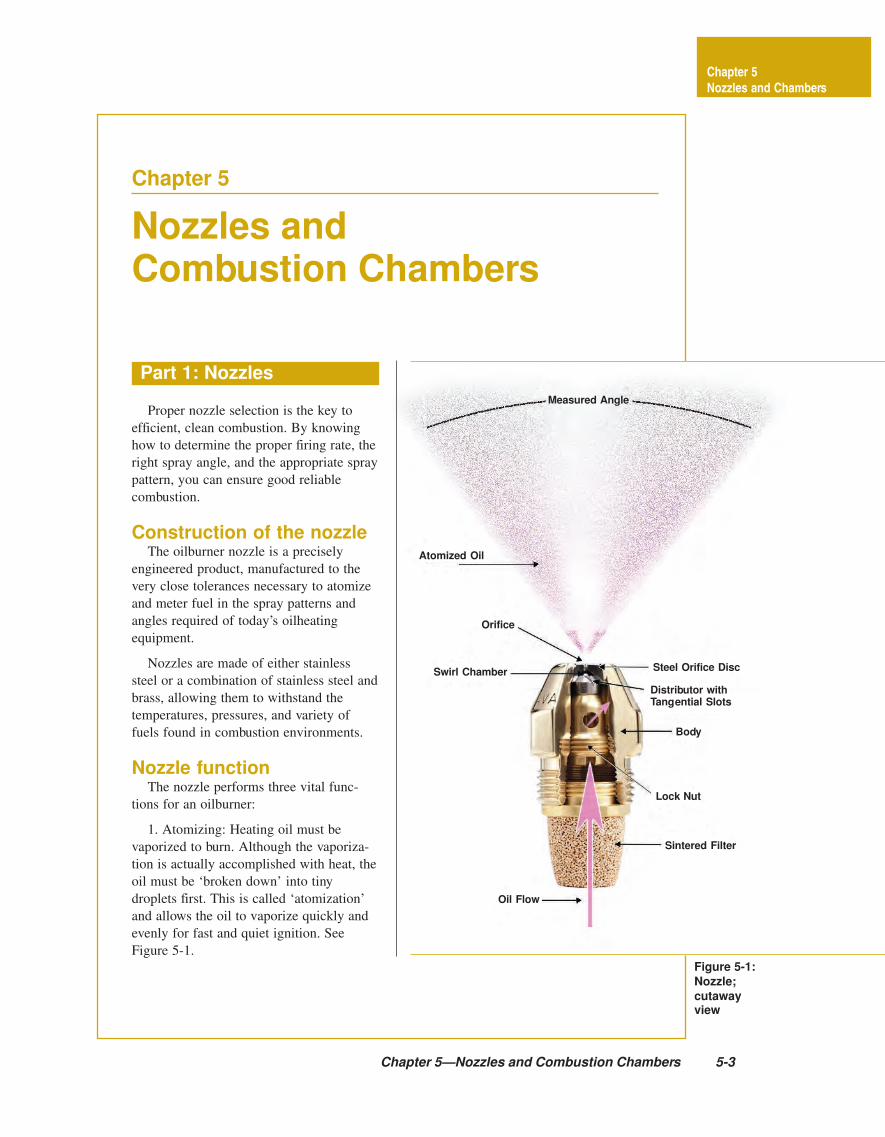
1. Atomizing: Heating oil must be
vaporized to burn. Although the vaporiza-
tion is actually accomplished with heat, the
oil must be ‘broken down’ into tiny
droplets first. This is called ‘atomization’
and allows the oil to vaporize quickly and
evenly for fast and quiet ignition. See
Figure 5-1.
Figure 5-1:
Nozzle;
cutawayview
Part 1: Nozzles
Chapter 5
Nozzles and Chambers
Measured Angle
Atomized Oil
Orifice
Swirl Chamber Steel Orifice Disc
Distributor withTangential Slots
Body
Lock Nut
Sintered Filter
Oil Flow
5-4 Nozzles and Combustion Chambers
pattern and angle best suited to the require-
ments of each specific burner and combus-
tion area.
Effects of pressureon nozzle performance
Historically, 100 PSI was considered
satisfactory for the fixed oil pressure
supplied to the nozzle, and all nozzle
manufacturers calibrate their nozzles at that
pressure. Many burner and appliance
(boilers, furnaces, and water heater)
manufacturers are recommending higher
pressures for their products. Higher
pressures create better atomization, i.e.
smaller droplets. See Figure 5-2.
Heating oil, under pressure (100 psi) passes
through the strainer to remove contamination,
then through a set of slots, cut at an angle
into the swirl chamber. The angle of the
ejected oil creates a high velocity swirl, like a
tornado. As the oil swirls against the swirl
chamber walls it creates an area of low
pressure in the center. This pressure differen-
tial moves the oil out through the orifice in a
hollow tube shape where it spreads into a
film that stretches until is ruptures into
billions of tiny droplets.
How a nozzle works
Chapter 5
Nozzles and Chambers
Me
an
Dro
p S
ize
(M
icro
n)
Oil Pressure (psi)
Figure 5-2: Fuel pressure vs. droplet size
Greater Oil Pressure Will Makethe Average Atomized Drop Smaller
2. Metering: A nozzle delivers
a fixed amount of atomized fuel to
the combustion chamber. The
amount of fuel is measured in
gallons-per-hour (GPH) at 100
pounds pressure. For burning rates
below five GPH, there are more
that 25 different flow rates each in
6 different spray angles and six or
more spray patterns.
3. Patterning: A nozzle is
expected to deliver the fuel to the
combustion area in a uniform spray
Chapter 5 —Nozzles and Combustion Chambers 5-5
Figure 5-4: Nozzle
spray patterns
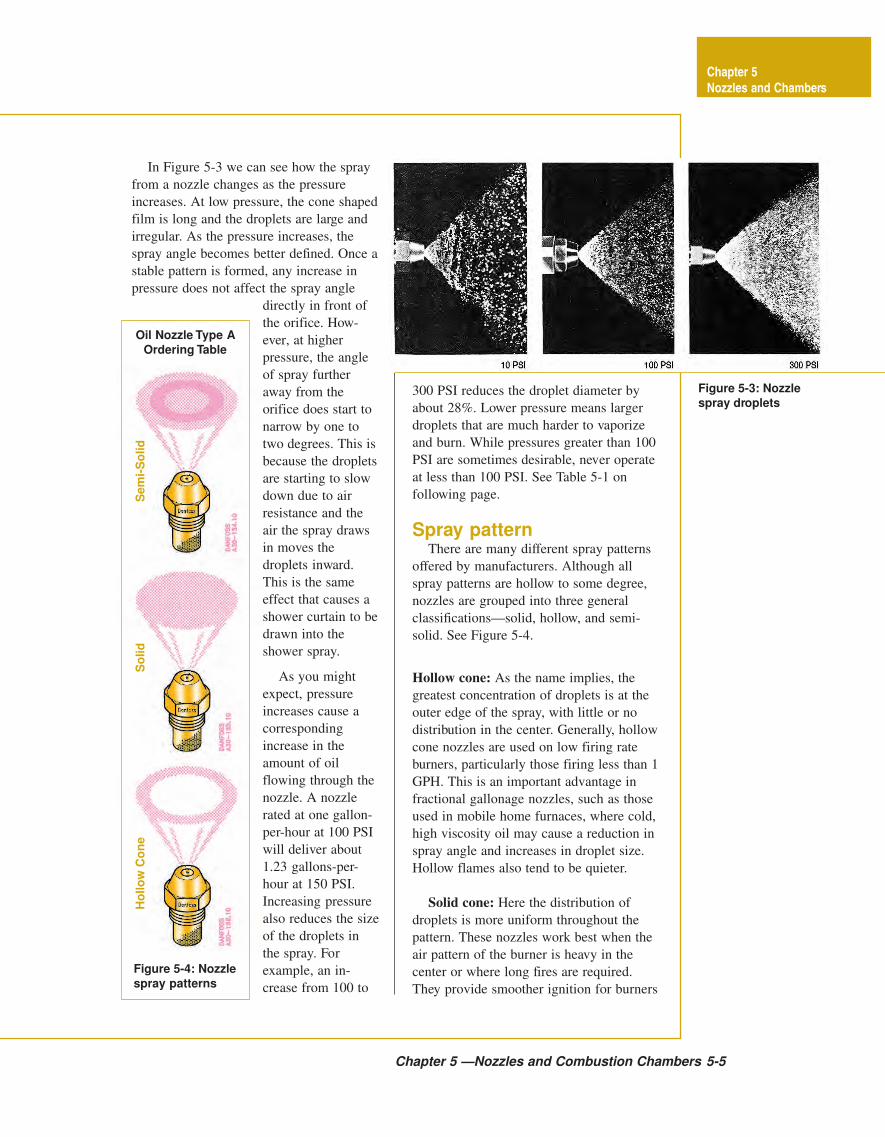
Figure 5-3: Nozzle
spray droplets
Sem
i-S
olid
So
lid
Ho
llo
w C
on
e
Chapter 5
Nozzles and Chambers
Oil Nozzle Type A
Ordering Table
300 PSI reduces the droplet diameter by
about 28%. Lower pressure means larger
droplets that are much harder to vaporize
and burn. While pressures greater than 100
PSI are sometimes desirable, never operate
at less than 100 PSI. See Table 5-1 on
following page.
Spray patternThere are many different spray patterns
offered by manufacturers. Although all
spray patterns are hollow to some degree,
nozzles are grouped into three general
classifications—solid, hollow, and semi-
solid. See Figure 5-4.
Hollow cone: As the name implies, the
greatest concentration of droplets is at the
outer edge of the spray, with little or no
distribution in the center. Generally, hollow
cone nozzles are used on low firing rate
burners, particularly those firing less than 1
GPH. This is an important advantage in
fractional gallonage nozzles, such as those
used in mobile home furnaces, where cold,
high viscosity oil may cause a reduction in
spray angle and increases in droplet size.
Hollow flames also tend to be quieter.
Solid cone: Here the distribution of
droplets is more uniform throughout the
pattern. These nozzles work best when the
air pattern of the burner is heavy in the
center or where long fires are required.
They provide smoother ignition for burners
In Figure 5-3 we can see how the spray
from a nozzle changes as the pressure
increases. At low pressure, the cone shaped
film is long and the droplets are large and
irregular. As the pressure increases, the
spray angle becomes better defined. Once a
stable pattern is formed, any increase in
pressure does not affect the spray angle
directly in front of
the orifice. How-
ever, at higher
pressure, the angle
of spray further
away from the
orifice does start to
narrow by one to
two degrees. This is
because the droplets
are starting to slow
down due to air
resistance and the
air the spray draws
in moves the
droplets inward.
This is the same
effect that causes a
shower curtain to be
drawn into the
shower spray.
As you might
expect, pressure
increases cause a
corresponding
increase in the
amount of oil
flowing through the
nozzle. A nozzle
rated at one gallon-
per-hour at 100 PSI
will deliver about
1.23 gallons-per-
hour at 150 PSI.
Increasing pressure
also reduces the size
of the droplets in
the spray. For
example, an in-
crease from 100 to
5-6 Nozzles and Combustion Chambers
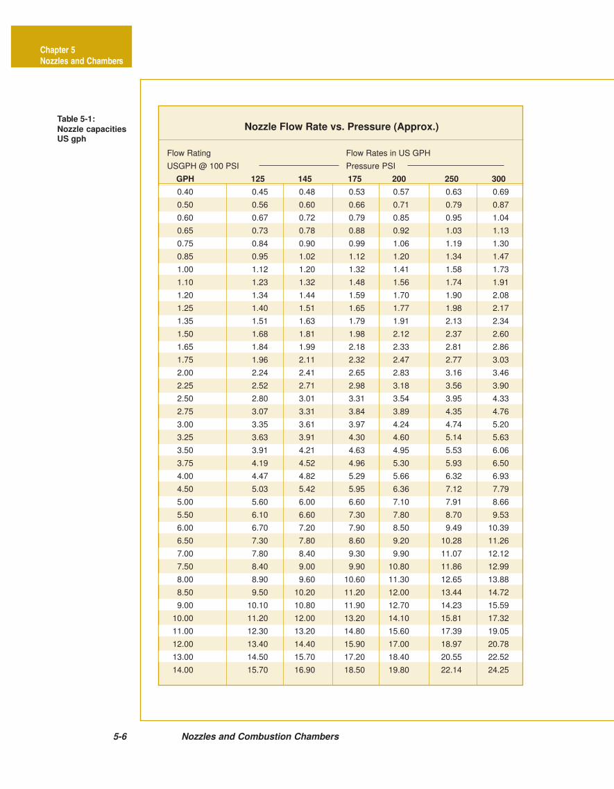
Table 5-1:
Nozzle capacitiesUS gph
Nozzle Flow Rate vs. Pressure (Approx.)
Flow Rating Flow Rates in US GPH
USGPH @ 100 PSI Pressure PSI
GPH 125 145 175 200 250 300
0.40 0.45 0.48 0.53 0.57 0.63 0.69
0.50 0.56 0.60 0.66 0.71 0.79 0.87
0.60 0.67 0.72 0.79 0.85 0.95 1.04
0.65 0.73 0.78 0.88 0.92 1.03 1.13
0.75 0.84 0.90 0.99 1.06 1.19 1.30
0.85 0.95 1.02 1.12 1.20 1.34 1.47
1.00 1.12 1.20 1.32 1.41 1.58 1.73
1.10 1.23 1.32 1.48 1.56 1.74 1.91
1.20 1.34 1.44 1.59 1.70 1.90 2.08
1.25 1.40 1.51 1.65 1.77 1.98 2.17
1.35 1.51 1.63 1.79 1.91 2.13 2.34
1.50 1.68 1.81 1.98 2.12 2.37 2.60
1.65 1.84 1.99 2.18 2.33 2.81 2.86
1.75 1.96 2.11 2.32 2.47 2.77 3.03
2.00 2.24 2.41 2.65 2.83 3.16 3.46
2.25 2.52 2.71 2.98 3.18 3.56 3.90
2.50 2.80 3.01 3.31 3.54 3.95 4.33
2.75 3.07 3.31 3.84 3.89 4.35 4.76
3.00 3.35 3.61 3.97 4.24 4.74 5.20
3.25 3.63 3.91 4.30 4.60 5.14 5.63
3.50 3.91 4.21 4.63 4.95 5.53 6.06
3.75 4.19 4.52 4.96 5.30 5.93 6.50
4.00 4.47 4.82 5.29 5.66 6.32 6.93
4.50 5.03 5.42 5.95 6.36 7.12 7.79
5.00 5.60 6.00 6.60 7.10 7.91 8.66
5.50 6.10 6.60 7.30 7.80 8.70 9.53
6.00 6.70 7.20 7.90 8.50 9.49 10.39
6.50 7.30 7.80 8.60 9.20 10.28 11.26
7.00 7.80 8.40 9.30 9.90 11.07 12.12
7.50 8.40 9.00 9.90 10.80 11.86 12.99
8.00 8.90 9.60 10.60 11.30 12.65 13.88
8.50 9.50 10.20 11.20 12.00 13.44 14.72
9.00 10.10 10.80 11.90 12.70 14.23 15.59
10.00 11.20 12.00 13.20 14.10 15.81 17.32
11.00 12.30 13.20 14.80 15.60 17.39 19.05
12.00 13.40 14.40 15.90 17.00 18.97 20.78
13.00 14.50 15.70 17.20 18.40 20.55 22.52
14.00 15.70 16.90 18.50 19.80 22.14 24.25
Chapter 5
Nozzles and Chambers
Chapter 5—Nozzles and Combustion Chambers 5-7
firing over 2 GPH. An interesting charac-
teristic of solid cone patterns is that they
become more and more hollow as flow
rates increase, particularly above 8 GPH. In
addition, increased pump pressure tends to
make both hollow and solid patterns more
hollow.
Semi-solid: Many burners perform well
with solid or hollow spray patterns. To
accommodate these designs, nozzle
manufacturers have developed patterns that
are a compromise between solid and
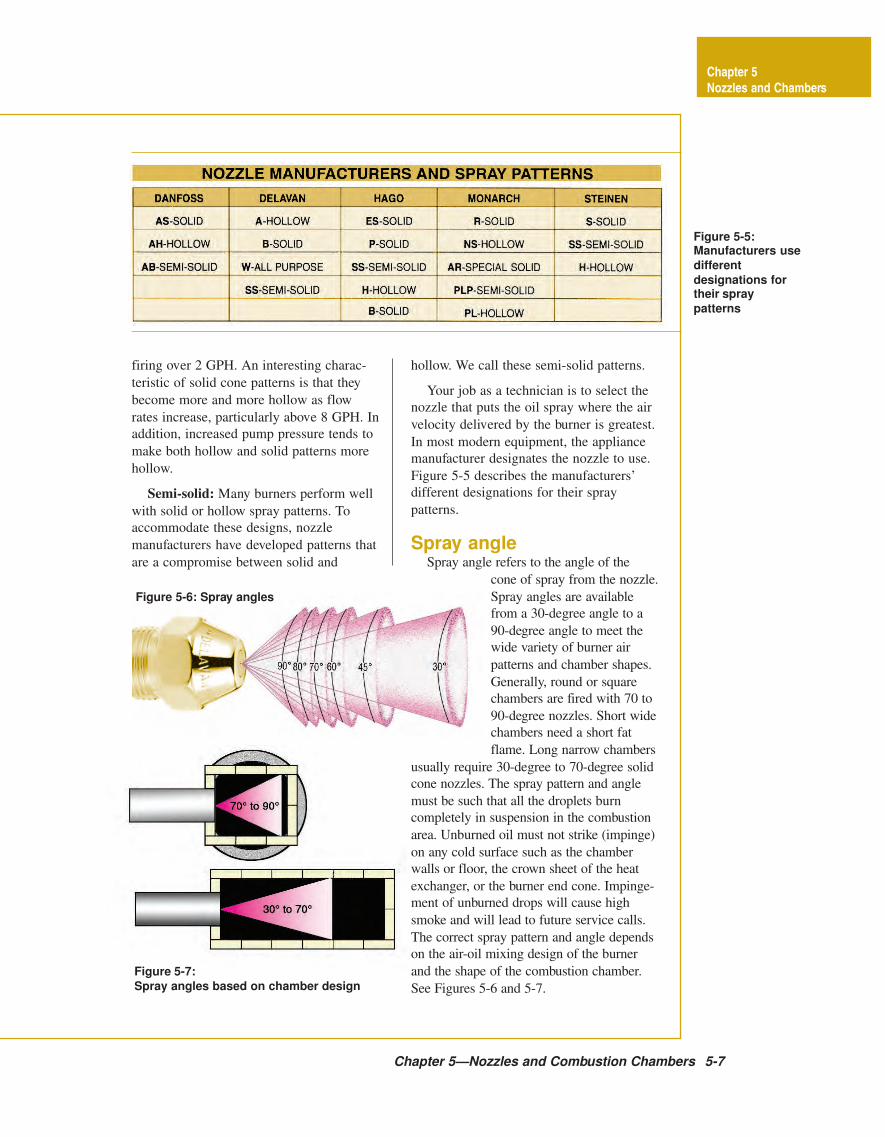
Figure 5-5:Manufacturers use
different
designations fortheir spray
patterns
hollow. We call these semi-solid patterns.
Your job as a technician is to select the
nozzle that puts the oil spray where the air
velocity delivered by the burner is greatest.
In most modern equipment, the appliance
manufacturer designates the nozzle to use.
Figure 5-5 describes the manufacturers’
different designations for their spray
patterns.
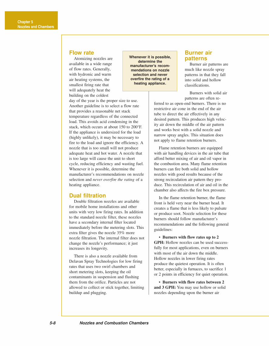
Spray angleSpray angle refers to the angle of the
cone of spray from the nozzle.
Spray angles are available
from a 30-degree angle to a
90-degree angle to meet the
wide variety of burner air
patterns and chamber shapes.
Generally, round or square
chambers are fired with 70 to
90-degree nozzles. Short wide
chambers need a short fat
flame. Long narrow chambers
usually require 30-degree to 70-degree solid
cone nozzles. The spray pattern and angle
must be such that all the droplets burn
completely in suspension in the combustion
area. Unburned oil must not strike (impinge)
on any cold surface such as the chamber
walls or floor, the crown sheet of the heat
exchanger, or the burner end cone. Impinge-
ment of unburned drops will cause high
smoke and will lead to future service calls.
The correct spray pattern and angle depends
on the air-oil mixing design of the burner
and the shape of the combustion chamber.
See Figures 5-6 and 5-7.
Figure 5-6: Spray angles
Figure 5-7:
Spray angles based on chamber design
Chapter 5
Nozzles and Chambers
Flow rateAtomizing nozzles are
available in a wide range
of flow rates. Generally,
with hydronic and warm
air heating systems, the
smallest firing rate that
will adequately heat the
building on the coldest
day of the year is the proper size to use.
Another guideline is to select a flow rate
that provides a reasonable net stack
temperature regardless of the connected
load. This avoids acid condensing in the
stack, which occurs at about 150 to 200°F.
If the appliance is undersized for the load
(highly unlikely), it may be necessary to
fire to the load and ignore the efficiency. A
nozzle that is too small will not produce
adequate heat and hot water. A nozzle that
is too large will cause the unit to short
cycle, reducing efficiency and wasting fuel.
Whenever it is possible, determine the
manufacturer’s recommendations on nozzle
selection and never overfire the rating of a
heating appliance.
Dual filtrationDouble filtration nozzles are available
for mobile home installations and other
units with very low firing rates. In addition
to the standard nozzle filter, these nozzles
have a secondary internal filter located
immediately before the metering slots. This
extra filter gives the nozzle 35% more
nozzle filtration. The internal filter does not
change the nozzle’s performance; it just
increases its longevity.
There is also a nozzle available from
Delavan Spray Technologies for low firing
rates that uses two swirl chambers and
short metering slots, keeping the oil
contaminants in suspension and flushing
them from the orifice. Particles are not
allowed to collect or stick together, limiting
buildup and plugging.
Burner airpatterns
Burner air patterns are
much like nozzle spray
patterns in that they fall
into solid and hollow
classifications.
Burners with solid air
patterns are often re-
ferred to as open-end burners. There is no
restrictive air cone in the end of the air
tube to direct the air effectively in any
desired pattern. This produces high veloc-
ity air down the middle of the air pattern
and works best with a solid nozzle and
narrow spray angles. This situation does
not apply to flame retention burners.
Flame retention burners are equipped
with air handling devices in the air tube that
afford better mixing of air and oil vapor in
the combustion area. Many flame retention
burners can fire both solid and hollow
nozzles with good results because of the
strong recirculation air pattern they pro-
duce. This recirculation of air and oil in the
chamber also affects the fire box pressure.
In the flame retention burner, the flame
front is held very near the burner head. It
creates a flame that is less likely to pulsate
or produce soot. Nozzle selection for these
burners should follow manufacturer’s
recommendations and the following general
guidelines:
• Burners with flow rates up to 2
GPH: Hollow nozzles can be used success-
fully for most applications, even on burners
with most of the air down the middle.
Hollow nozzles in lower firing rates
produce the quietest operation. It is often
better, especially in furnaces, to sacrifice 1
or 2 points in efficiency for quiet operation.
• Burners with flow rates between 2
and 3 GPH: You may use hollow or solid
nozzles depending upon the burner air
5-8 Nozzles and Combustion Chambers
Whenever it is possible,
determine themanufacturer’s recom-
mendations on nozzle
selection and neveroverfire the rating of a
heating appliance.
Chapter 5
Nozzles and Chambers
pattern. At this higher firing rate, spray
patterns are not as critical.
• Burners with firing rates above 3
GPH: Here it is advisable to standardize on
solid nozzles which produce smoother
ignition in most burners. Burners with
hollow air patterns are the exception. Check
the manufacturers’ recommendations.
Nozzle brand interchangeReplacing nozzles of one brand with
those of another can sometimes present
problems. There are subtle differences
between manufacturers because they use
different methods of production and
evaluation.
The burner manufacturers test their
burners in different appliances and deter-
mine what type nozzle, from which nozzle
manufacturer, works best in that particular
application. Burner manufacturers publish
nozzle recommendations called OEM
Specification Guides. Be sure to have this
information at hand.
If you are working on a unit not listed in
the Specification Guide, you will find that
generally, all hollow nozzles have similar
spray patterns and may be interchangeable.
The variation shows up mainly in the solid
nozzles, and if you must change brands,
you will have to do some testing to deter-
mine the best nozzle for that application.
Check with your supply house to secure a
nozzle interchange chart to help you in your
testing.
Nozzle care andservice suggestions
Never, under any conditions, interchange
the inner parts of a nozzle with those of
another nozzle. Each nozzle component is
matched exactly to all the other components
of that nozzle. In fact, you should leave a
nozzle in its original container until you
install it. You should store all your nozzles
in a proper nozzle box. They are available
from the nozzle manufacturers.
Handle nozzles carefully. Pick them up
by the hex flats only. Do not touch the
strainer or orifice. Even clean hands have
enough dirt on them to plug up the tiny
slots inside the nozzle. Obviously, you
should never disassemble a nozzle you plan
to use.
Only install nozzles with clean tools to
reduce the possibility of contamination. If
possible, use a nozzle changer or nozzle
wrench when changing a nozzle. Most
open-end wrench handles are too long and
increase the possibility of stripping the
nozzle adapter threads. Before installing a
new nozzle, flush out the nozzle line and
adapter with clean oil, kerosene, or a
solvent.
Before you install the nozzle in the
adapter, be sure the inside of the adapter is
clean and free of carbon or contamination.
Carefully examine the sealing surface of
the adapter to be sure there are no
scratches or nicks. These can be caused by
careless handling, or just wear and tear. If
it is scratched or nicked, then replace the
adapter. Do not take a chance here. A leak
between the nozzle and the adapter can
cause serious problems. Do not put any-
thing on the nozzle threads! Screw the
nozzle into the adapter one-eighth to one-
quarter turn past hand tight (about 88 to
138 pounds of torque).
The nozzle orifice face is polished to a
mirror finish. Do not ruin it with a wire or
pin, or by bumping it with a wrench. This
will ruin the spray. If a nozzle is dirty, or
plugged, change it. It is impossible to clean
it out properly. It is tempting, especially in
the middle of the night to try to clean out
the orifice with a pin or tooth pick. It will
not work. Replace it!
A good quality nozzle should last at
least two heating seasons. Contamination
Chapter 5—Nozzles and Combustion Chambers 5-9
Chapter 5
Nozzles and Chambers
5-10 Nozzles and Combustion Chambers
Figure 5-8
Figure 5-9
Chapter 5
Nozzles and Chambers
Proper Spray Angle Matched to Air Flow
Fuel Spray Angle too Wide
Fuel Spray Angle too Narrow
Nozzle
Inches
Inch
es
Inches
Inch
es
Inches
Inch
es
Nozzle
Nozzle
and excessive heat are the main causes of
nozzle failure. Contamination can be
limited by installing a good oil filter in the
supply line. If there are excessive tank
bottom sediments in the tank, you may
need to clean the tank and adopt a fuel
additive program. For severe cases, replace
the tank.
Nozzles should not be very hot when
operating because of the amount of air and
fuel traveling past them. Nozzles overheat
from poor or no over-fire draft. Over-fire
draft should be at least -.01" to keep
nozzles cool. There are some exceptions to
this rule. As usual, manufacturer’s instruc-
tions take precedence. Be sure the end of
the burner air tube does not extend into the
chamber. The face of the end tube should
be flush with the face of the chamber, or
recessed about one quarter inch.
Air-oil mixingand flame patterns
What constitutes a perfect oilburner
flame? Theoretically, each droplet of oil
that leaves the nozzle orifice should be
completely surrounded by air. It should be
vaporized and then burst into flame—
totally burning all the hydrogen and carbon
atoms in the fuel. This air volume, gener-
ated by the burner fan, and, in most
applications, aided by the draft-over-the-
fire, should be adjusted to deliver the exact
amount of air required by the fuel being
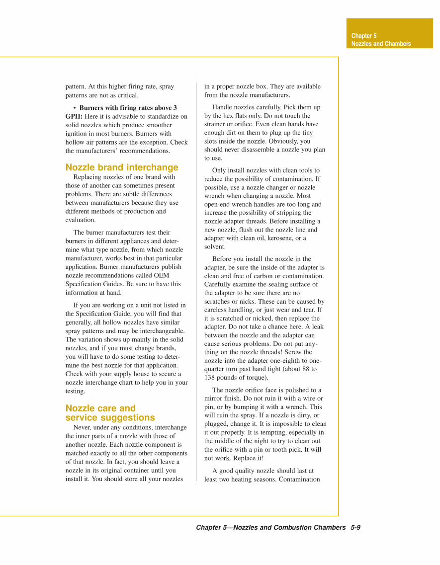
fed through the nozzle, see Figure 5-8.
It is impossible to reach this perfect
state in the field, but it is a good target to
shoot for. The closer you come to this
perfect air-oil match, the cleaner, quieter,
more efficient and odor free the flame will
be.
There are six elements for the perfect
air-oil match. They are: air volume, oil
volume, oil pressure, oil spray pattern, oil
spray angle, and the air pattern of the
burner. The air pattern of the burner is the
Chapter 5—Nozzles and Combustion Chambers 5-11
Figure 5-10:
Viscosity vs.temperature
change
Chapter 5
Nozzles and Chambers
Viscosity vs. TemperatureNo. 2 Fueloil
Vis
co
sit
y, S
SU
Temperature °F
most important factor. This is unfortunate,
because you cannot control or adjust air
pattern; it is fixed by the burner design.
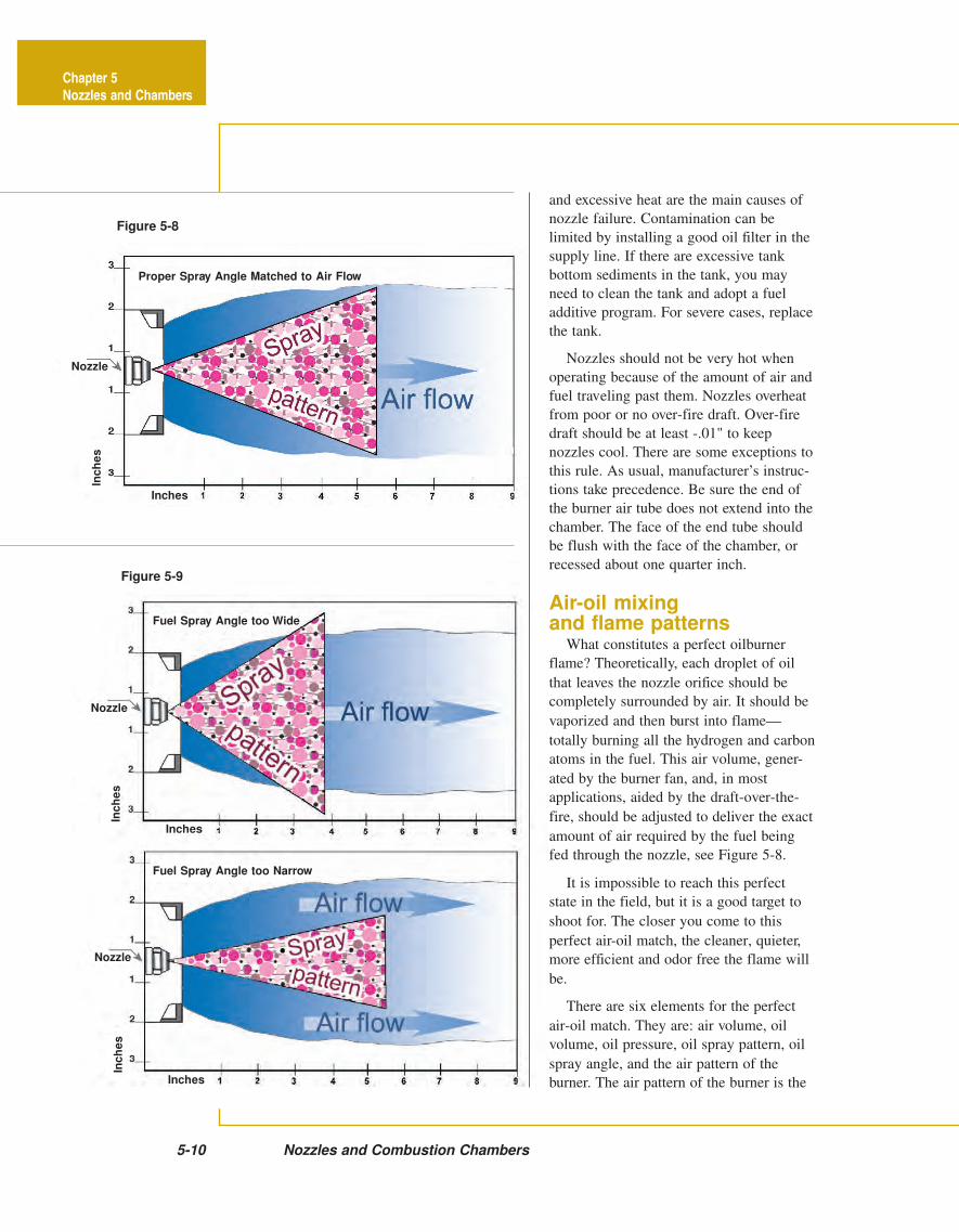
Also, you cannot see the burner air pattern;
you must rely on trial and error in our
quest for perfection. See Figure 5-9.
Your tools in your search for the perfect
flame are: the smoke tester, stack thermom-
eter, draft gauge, pressure gauge, CO2 or
O2 tester, the manufacturer’s recommenda-
tions and the experience of the person who
was there before you. Always use the
condition of the unit as you found it as
your best guide to what needs to be done.
If you find the unit running well and
reasonably clean, the nozzle installed in the
unit is probably pretty close to being the
right one. However, if the unit is not
running well, it may be time for some
changes. The single greatest factor in
combustion inefficiency is excess air. It
absorbs large quantities of heat and carries
it wastefully up the chimney. It also
reduces the flame temperature, decreasing
the rate of heat transfer to the heat ex-
changer. Both of these raise stack tempera-
tures, which lower efficiency.
The best burner adjustment is one that
allows a smokeless, sootless operation with
a minimum of excess air. We determine
excess air by measuring the percentage of
oxygen (O2) in the flue gases. You will
learn more about this in the combustion
chapter.
Nozzle applicationprocedure
If the manufacturer’s recommendations
are not available, or if you are upgrading
an old unit with a new burner, the follow-
ing is a step-by-step procedure you may
use for selecting the best nozzle.
1. Set the over-the-fire draft to -.02",
check the oil pressure, and install a nozzle
that does not exceed the rating of the
appliance.
2. Start with an 80-degree hollow
nozzle, and adjust for a 1 smoke and mark
the air band opening.
3. Try an 80-degree solid nozzle and
take another smoke test. If it is lighter, you
have a solid air pattern; if the smoke is
heavier, it is hollow.
4. Try a 60-degree hollow or solid
nozzle as indicated by the previous two
tests.
5. Select the nozzle that creates the
lowest smoke and highest efficiency.
6. Once the tests are completed, record
the results. Post the results near the burner
and report them to the office where they
should become a permanent part of the
customer’s service history.
Effects of viscosityon nozzle performance
One of the important factors affecting
nozzle performance is the viscosity of the
fuel. Viscosity is the resistance to flow—
the thickness of the fuel. Thus, gasoline is
“thin”, having a lower viscosity, while
grease is “thick”, having a higher viscosity.
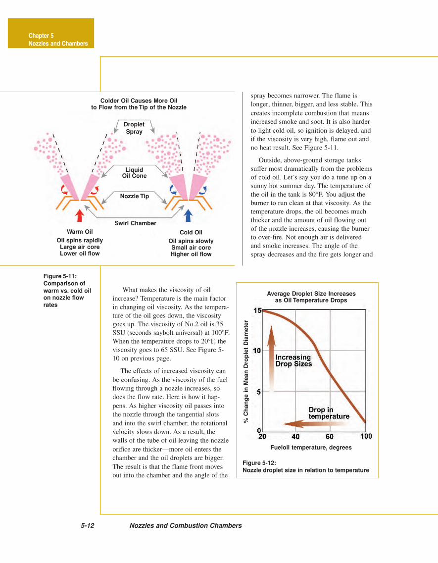
Figure 5-11:
Comparison of
warm vs. cold oilon nozzle flow
rates
REDO
Figure 5-12:
Nozzle droplet size in relation to temperature
5-12 Nozzles and Combustion Chambers
Average Droplet Size Increasesas Oil Temperature Drops
Warm Oil
Oil spins rapidlyLarge air coreLower oil flow
Cold Oil
Oil spins slowlySmall air coreHigher oil flow
Colder Oil Causes More Oilto Flow from the Tip of the Nozzle
Fueloil temperature, degrees
Chapter 5
Nozzles and Chambers
Swirl Chamber
Nozzle Tip
LiquidOil Cone
Droplet
Spray
% C
ha
ng
e i
n M
ean
Dro
ple
t D
iam
ete
r
Fueloil temperature, degrees
spray becomes narrower. The flame is
longer, thinner, bigger, and less stable. This
creates incomplete combustion that means
increased smoke and soot. It is also harder
to light cold oil, so ignition is delayed, and
if the viscosity is very high, flame out and
no heat result. See Figure 5-11.
Outside, above-ground storage tanks
suffer most dramatically from the problems
of cold oil. Let’s say you do a tune up on a
sunny hot summer day. The temperature of
the oil in the tank is 80°F. You adjust the
burner to run clean at that viscosity. As the
temperature drops, the oil becomes much
thicker and the amount of oil flowing out
of the nozzle increases, causing the burner
to over-fire. Not enough air is delivered
and smoke increases. The angle of the
spray decreases and the fire gets longer and
What makes the viscosity of oil
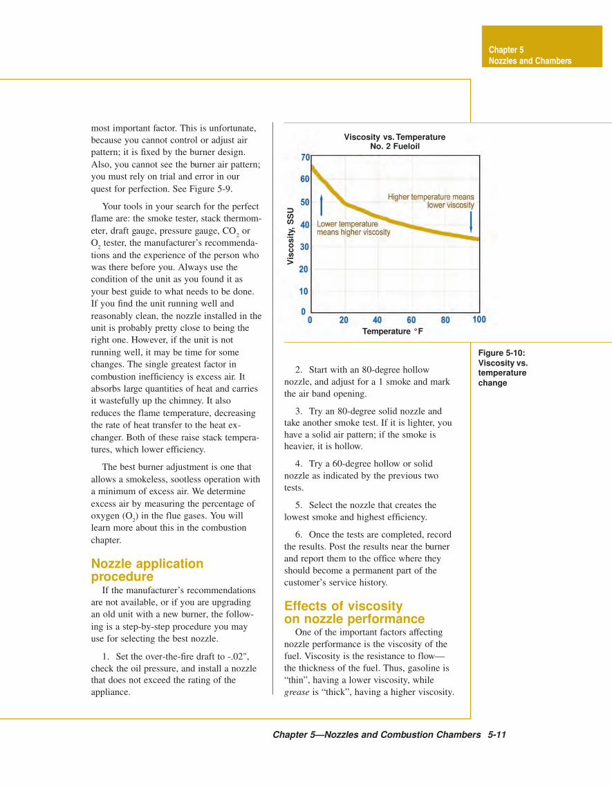
increase? Temperature is the main factor
in changing oil viscosity. As the tempera-
ture of the oil goes down, the viscosity
goes up. The viscosity of No.2 oil is 35
SSU (seconds saybolt universal) at 100°F.
When the temperature drops to 20°F, the
viscosity goes to 65 SSU. See Figure 5-
10 on previous page.
The effects of increased viscosity can
be confusing. As the viscosity of the fuel
flowing through a nozzle increases, so
does the flow rate. Here is how it hap-
pens. As higher viscosity oil passes into
the nozzle through the tangential slots
and into the swirl chamber, the rotational
velocity slows down. As a result, the
walls of the tube of oil leaving the nozzle
orifice are thicker—more oil enters the
chamber and the oil droplets are bigger.
The result is that the flame front moves
out into the chamber and the angle of the
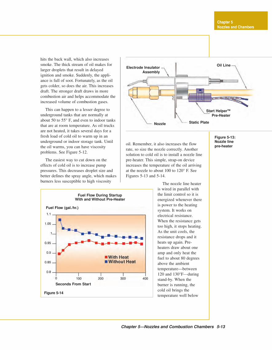
Chapter 5—Nozzles and Combustion Chambers 5-13
Figure 5-14
Figure 5-13:Nozzle line
pre-heater
Fuel Flow During StartupWith and Without Pre-Heater
Chapter 5
Nozzles and Chambers
Electrode Insulator
Assembly
Nozzle Static Plate
Start HelperTM
Pre-Heater
Oil Line
Seconds From Start
Fuel Flow (gal./hr.)
hits the back wall, which also increases
smoke. The thick stream of oil makes for
larger droplets that result in delayed
ignition and smoke. Suddenly, the appli-
ance is full of soot. Fortunately, as the oil
gets colder, so does the air. This increases
draft. The stronger draft draws in more
combustion air and helps accommodate the
increased volume of combustion gases.
This can happen to a lesser degree to
underground tanks that are normally at
about 50 to 55° F, and even to indoor tanks
that are at room temperature. As oil trucks
are not heated, it takes several days for a
fresh load of cold oil to warm up in an
underground or indoor storage tank. Until
the oil warms, you can have viscosity
problems. See Figure 5-12.
The easiest way to cut down on the
effects of cold oil is to increase pump
pressures. This decreases droplet size and
better defines the spray angle, which makes
burners less susceptible to high viscosity
oil. Remember, it also increases the flow
rate, so size the nozzle correctly. Another
solution to cold oil is to install a nozzle line
pre-heater. This simple, strap-on device
increases the temperature of the oil arriving
at the nozzle to about 100 to 120° F. See
Figures 5-13 and 5-14.
The nozzle line heater
is wired in parallel with
the limit control so it is
energized whenever there
is power to the heating
system. It works on
electrical resistance.
When the resistance gets
too high, it stops heating.
As the unit cools, the
resistance drops and it
heats up again. Pre-
heaters draw about one
amp and only heat the
fuel to about 80 degrees
above the ambient
temperature—between
120 and 130°F—during
stand-by. When the
burner is running, the
cold oil brings the
temperature well below
5-14 Nozzles and Combustion Chambers
There are three basic causes of
after-drip—a defective pump shut
off valve, air entrapped in the
nozzle line, and oil expansion in
the nozzle line caused by exces-
sive radiated heat at shut down.
Chapter 5
Nozzles and Chambers
120°. Yet another way to help with this
problem is to blend kerosene or additives
with heating oil.
Thermal stabilityIf you find a fuel failure but the filter
and strainer are clean and the nozzle is
plugged with coke (a dull black substance),
the problem is probably thermal stability.
Oil can become unstable in the prolonged
presence of heat, particularly when in
contact with copper and other “yellow”
metals. As the oil sits in the nozzle and
drawer assembly and its temperature rises,
it can form coke. This is more of an
installation issue than a fuel issue.
Nozzles should not get
hot. If the nozzle is hot
enough to overheat the oil,
you probably have either a
bad draft situation, an old
hard brick chamber
reflecting excessive heat
back on the nozzle after
shut down, an after-drip
problem, or a draw
assembly and end cone
sticking into the chamber. There are good
mechanical fixes for these problems—i.e.
post purge, draft inducers, interrupted
ignition, ceramic chamber liners, and end
cone amulets, to name a few.
If you encounter a thermal stability
problem, find out what is causing the
nozzle to get hot. The problem is most
likely to occur after burner shutdown.
Check the over-fire draft after shut-down.
Check to see if the draft regulator closes
after shutdown. If it stays open, it will
reduce draft over-the-fire needed to cool
the nozzle. Check electrode settings and
the type of chamber. Check to be sure that
the end-cone is flush or slightly recessed
from the chamber face. Check for after-
drip. Any of these problems could be the
cause of your thermal instability.
Another cause of overheating is a hard
brick chamber. When replacing an old non-
flame retention burner with a new flame
retention burner, it is tempting to leave the
old chamber in place. The problem is, new
burners have much higher flame tempera-
tures than the old burners. It did not matter
with the old burner’s cool flame that the
hard brick chamber held its heat for hours.
The white-hot flame from the new burners,
however, heats the chamber to very high
temperatures. When the burner shuts off, the
old chamber reflects all this heat back and
overheats the nozzle.
The solution is to replace the old cham-
ber or line it with a ceramic liner. In some
cases, with big old dry base boilers, you can
fill in the old chamber and install the new
burner in the clean-out door, firing against a
target wall—essentially creating a wet base
boiler.
Many units are very tight or operate
without a chimney and offer little or no
over-fire draft. The best way to avoid nozzle
overheating in these situations is motor-off-
delay (commonly called post-purge.) Using
a solenoid valve, the primary control shuts
off the flow of oil but keeps the burner
running for a few minutes, blowing air from
the burner air intake through the air tube and
past the nozzle—keeping it cool.
Nozzle after-dripThe quickest way to soot up a heat
exchanger is nozzle after- drip. This happens
when oil drips from the nozzle orifice after
the burner shuts down. If the combustion
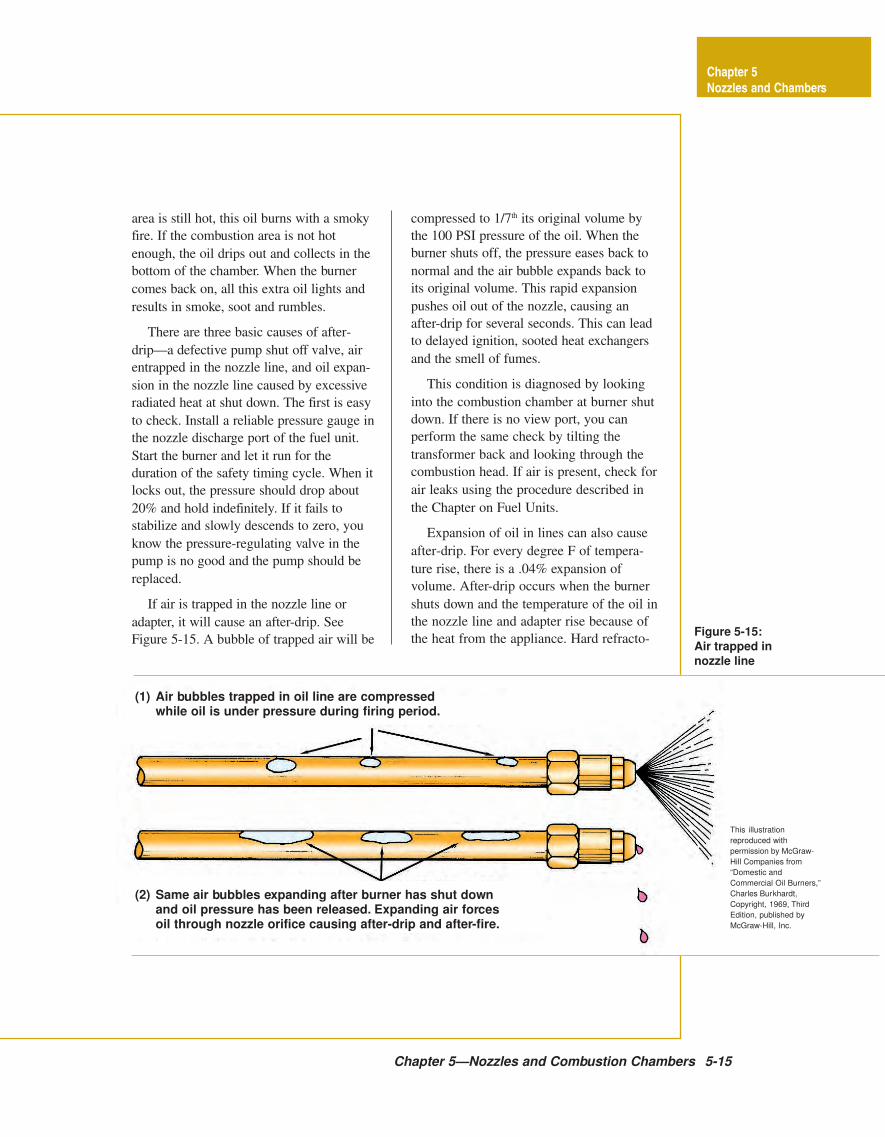
Figure 5-15:
Air trapped in
nozzle line
Chapter 5—Nozzles and Combustion Chambers 5-15
Chapter 5
Nozzles and Chambers
(1) Air bubbles trapped in oil line are compressedwhile oil is under pressure during firing period.
(2) Same air bubbles expanding after burner has shut downand oil pressure has been released. Expanding air forcesoil through nozzle orifice causing after-drip and after-fire.
This illustration
reproduced with
permission by McGraw-
Hill Companies from
“Domestic and
Commercial Oil Burners,”
Charles Burkhardt,
Copyright, 1969, Third
Edition, published by
McGraw-Hill, Inc.
area is still hot, this oil burns with a smoky
fire. If the combustion area is not hot
enough, the oil drips out and collects in the
bottom of the chamber. When the burner
comes back on, all this extra oil lights and
results in smoke, soot and rumbles.
There are three basic causes of after-
drip—a defective pump shut off valve, air
entrapped in the nozzle line, and oil expan-
sion in the nozzle line caused by excessive
radiated heat at shut down. The first is easy
to check. Install a reliable pressure gauge in
the nozzle discharge port of the fuel unit.
Start the burner and let it run for the
duration of the safety timing cycle. When it
locks out, the pressure should drop about
20% and hold indefinitely. If it fails to
stabilize and slowly descends to zero, you
know the pressure-regulating valve in the
pump is no good and the pump should be
replaced.
If air is trapped in the nozzle line or
adapter, it will cause an after-drip. See
Figure 5-15. A bubble of trapped air will be
compressed to 1/7th its original volume by
the 100 PSI pressure of the oil. When the
burner shuts off, the pressure eases back to
normal and the air bubble expands back to
its original volume. This rapid expansion
pushes oil out of the nozzle, causing an
after-drip for several seconds. This can lead
to delayed ignition, sooted heat exchangers
and the smell of fumes.
This condition is diagnosed by looking
into the combustion chamber at burner shut
down. If there is no view port, you can
perform the same check by tilting the
transformer back and looking through the
combustion head. If air is present, check for
air leaks using the procedure described in
the Chapter on Fuel Units.
Expansion of oil in lines can also cause
after-drip. For every degree F of tempera-
ture rise, there is a .04% expansion of
volume. After-drip occurs when the burner
shuts down and the temperature of the oil in
the nozzle line and adapter rise because of
the heat from the appliance. Hard refracto-
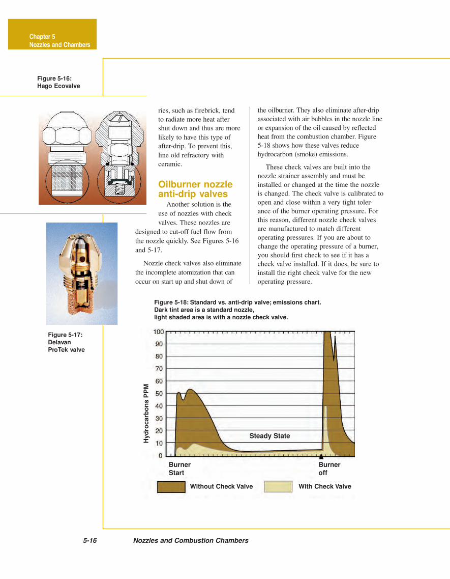
Figure 5-17:
Delavan
ProTek valve
5-16 Nozzles and Combustion Chambers
Figure 5-18: Standard vs. anti-drip valve; emissions chart.
Dark tint area is a standard nozzle,
light shaded area is with a nozzle check valve.
Figure 5-16:
Hago Ecovalve
Without Check Valve With Check Valve
Chapter 5
Nozzles and Chambers
BurnerStart
Burneroff
Hyd
roc
arb
on
s P
PM
Steady State
ries, such as firebrick, tend
to radiate more heat after
shut down and thus are more
likely to have this type of
after-drip. To prevent this,
line old refractory with
ceramic.
Oilburner nozzleanti-drip valves
Another solution is the
use of nozzles with check
valves. These nozzles are
designed to cut-off fuel flow from
the nozzle quickly. See Figures 5-16
and 5-17.
Nozzle check valves also eliminate
the incomplete atomization that can
occur on start up and shut down of
the oilburner. They also eliminate after-drip
associated with air bubbles in the nozzle line
or expansion of the oil caused by reflected
heat from the combustion chamber. Figure
5-18 shows how these valves reduce
hydrocarbon (smoke) emissions.
These check valves are built into the
nozzle strainer assembly and must be
installed or changed at the time the nozzle
is changed. The check valve is calibrated to
open and close within a very tight toler-
ance of the burner operating pressure. For
this reason, different nozzle check valves
are manufactured to match different
operating pressures. If you are about to
change the operating pressure of a burner,
you should first check to see if it has a
check valve installed. If it does, be sure to
install the right check valve for the new
operating pressure.
Chapter 5—Nozzles and Combustion Chambers 5-17
Chapter 5
Nozzles and Chambers
IntroductionThe flame from the oilburner is con-
tained in the combustion chamber. A
chamber must be made of the proper
material to handle the high flame tempera-
tures. It must be properly sized for the
nozzle-firing rate and it must be the correct
shape and the proper height. Combustion
chambers have a profound effect on the
first three of the four rules for good heating
oil combustion:
1. The oil must be completely atomized
and vaporized.
2. The oil must burn in complete
suspension.
3. The mixture of air and oil vapors will
burn best in the presence of hot
refractory.
4. A minimum amount of air must be
supplied for complete, efficient
combustion.
To burn the oil in suspension means that
the fire must never touch any surface—
especially a cold one. The cold surface will
reduce the temperature of the gases turning
the vaporized carbon in the fuel into smoke
and soot before it has a chance to burn. For
combustion to be self-sustaining, the heat
produced by the flame must be sufficient to
ignite the fresh mixture of oil vapor and air
coming into the combustion zone from the
burner. The hotter the area around the
burning zone, the easier and more com-
pletely the oil will burn.
The combustion chamber provides the
necessary room for all the oil to burn before
contacting or impinging on cold surfaces. It
also reflects heat back into the burning
zone, ensuring clean, quick combustion. If
the chamber is too small or the wrong shape
for the burner air pattern, or the nozzle is
too close to the floor, there will be flame
impingement, causing smoke and soot. With
non-flame retention burners, an oversized
chamber refractory will not reflect enough
heat back into the burning zone to burn the
carbon—smoke will be created. If the
chamber sides are too low, combustibles
will spill over the top and burn incom-
pletely. It is your job to be able to diagnose
an incorrectly built chamber as well as to
build and design a correct one.
Chamber materialsChambers should heat up quickly, reflect
as much heat back into the burning zone as
possible, and cool off quickly when the
burner shuts down. There are five common
types of materials used in combustion
chamber construction.
Insulating fire brick: The porous nature
and lightness of this brick makes it highly
resistant to the penetration of heat. The side
of the brick facing the fire glows red hot in
about 15 seconds while the rear surface
remains relatively cool. (The bricks come in
a variety of sizes and are available in pre-
cast chambers). For fires up to 3 GPH, you
can use 2000°F firebrick. It will take up to
3000-degree temperatures, but structurally it
cannot take the starting violence of a large
fire. Proper refractory cement should be
used with the insulating brick so the
expansion of the brick and cement will be
equal.
Common fire brick or hard brick: This
weighs more than insulating brick and it
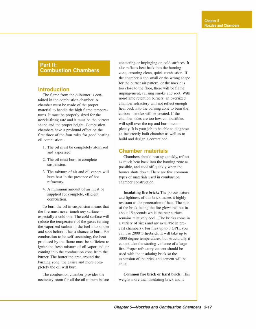
Part II:Combustion Chambers
Figure 5-19:Combustion
chamber design
PreferredShape
5-18 Nozzles and Combustion Chambers
Chapter 5
Nozzles and Chambers
Good Combustion
EddyCurrentPockets
EddyCurrentPockets
chamber first. If the old chamber is deterio-
rated, wrap the material with a stainless
steel binder. If the old chamber was too
small or the wrong shape, lining it will not
help. Ceramic chambers become brittle
after firing. Do not touch it with a vacuum
cleaner hose or flame mirror after it has
been used. The material is intended for
firing rates below 3 GPH, and will with-
stand about 2,300°F. It can be purchased
by the foot or is available in pre-shaped
sizes. The material gives quieter operation,
less smoke and fuel savings.
Molded chamber: Many manufacturers
install their own molded chambers in their
packaged units. They are usually made of
semi-insulating refractory material.
Chamber shapesThe best shape for a chamber is round or
oval so the hot gases can sweep back
smoothly. In a square or rectangular cham-
ber, eddy currents develop in the corners
requiring more excess air to burn com-
pletely. The correct height is most important.
All combustion should take place in the
chamber. There should be little if any flame
above the chamber. The top of the chamber
should be about as far above the nozzle as
the floor is below it. See Figure 5-19.
Sizing the chamber
The gallons-per-hour firing rate deter-
mines the size of the chamber. A firing rate
of .75 to 3 GPH requires 80 square inches of
chamber floor space per gallon of fuel. A
firing rate from 3.5 to 5 GPH requires 90
square inches, and over 5.5 GPH requires
100 square inches per gallon. See Table 5-2
and Figure 5-20.
Installing a low
firing rate chamber
There are many very good pre-cast
absorbs much more heat before it begins
reflecting any back into the burning zone. It
is unsatisfactory for residential purposes,
but is used in commercial units because it
stands up better to the shock loads of high
firing rates. The brick comes in the standard
size of 9" long by 4.5" high, and 2.5" deep.
It is also made in runners and pre-cast
chambers.
Metal fire chambers: Metal chambers
are used primarily in factory-built “pack-
aged units” because they can be shipped in
place without damage or breakage and do
not require bracing. Metal cham-
bers are much better than com-
mon fire brick. However, they are
sensitive to improper nozzle
selection and overfiring. A nozzle-
firing rate that is too high, or a
lopsided fire can distort or even
burn a hole through the wall of
the chamber. Direct flame im-
pingement on the chamber must
be avoided. Metal chambers must
have free flowing air behind them
to keep them from burning
through. Do not put any kind of
insulating material, including
soot, around the chamber. The
higher flame temperatures of
flame retention burners is tough
on metal chambers; it is usually a
good idea to replace a burned out
metal chamber with a pre-cast
ceramic one.
Ceramic chambers: Ceramic
material is excellent for chambers.
It reflects heat quickly while
absorbing very little and it is easy
to install. If the old chamber is
still in good condition, you may
use ceramic blanket material to
line the old chamber. Be sure to
seal any air leaks in the old
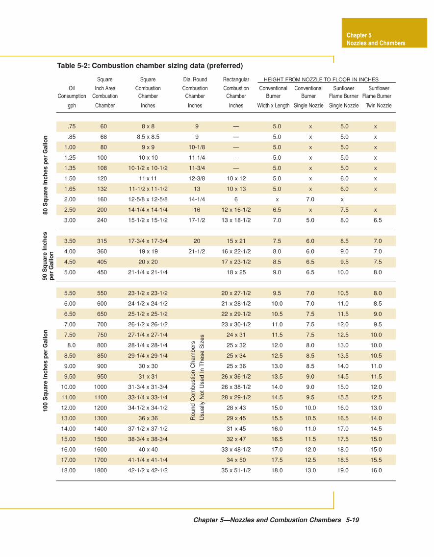
Square Square Dia. Round Rectangular
Oil Inch Area Combustion Combustion Combustion Conventional Conventional Sunflower Sunflower
Consumption Combustion Chamber Chamber Chamber Burner Burner Flame Burner Flame Burner
gph Chamber Inches Inches Inches Width x Length Single Nozzle Single Nozzle Twin Nozzle
.75 60 8 x 8 9 — 5.0 x 5.0 x
.85 68 8.5 x 8.5 9 — 5.0 x 5.0 x
1.00 80 9 x 9 10-1/8 — 5.0 x 5.0 x
1.25 100 10 x 10 11-1/4 — 5.0 x 5.0 x
1.35 108 10-1/2 x 10-1/2 11-3/4 — 5.0 x 5.0 x
1.50 120 11 x 11 12-3/8 10 x 12 5.0 x 6.0 x
1.65 132 11-1/2 x 11-1/2 13 10 x 13 5.0 x 6.0 x
2.00 160 12-5/8 x 12-5/8 14-1/4 6 x 7.0 x
2.50 200 14-1/4 x 14-1/4 16 12 x 16-1/2 6.5 x 7.5 x
3.00 240 15-1/2 x 15-1/2 17-1/2 13 x 18-1/2 7.0 5.0 8.0 6.5
3.50 315 17-3/4 x 17-3/4 20 15 x 21 7.5 6.0 8.5 7.0
4.00 360 19 x 19 21-1/2 16 x 22-1/2 8.0 6.0 9.0 7.0
4.50 405 20 x 20 17 x 23-1/2 8.5 6.5 9.5 7.5
5.00 450 21-1/4 x 21-1/4 18 x 25 9.0 6.5 10.0 8.0
5.50 550 23-1/2 x 23-1/2 20 x 27-1/2 9.5 7.0 10.5 8.0
6.00 600 24-1/2 x 24-1/2 21 x 28-1/2 10.0 7.0 11.0 8.5
6.50 650 25-1/2 x 25-1/2 22 x 29-1/2 10.5 7.5 11.5 9.0
7.00 700 26-1/2 x 26-1/2 23 x 30-1/2 11.0 7.5 12.0 9.5
7.50 750 27-1/4 x 27-1/4 24 x 31 11.5 7.5 12.5 10.0
8.0 800 28-1/4 x 28-1/4 25 x 32 12.0 8.0 13.0 10.0
8.50 850 29-1/4 x 29-1/4 25 x 34 12.5 8.5 13.5 10.5
9.00 900 30 x 30 25 x 36 13.0 8.5 14.0 11.0
9.50 950 31 x 31 26 x 36-1/2 13.5 9.0 14.5 11.5
10.00 1000 31-3/4 x 31-3/4 26 x 38-1/2 14.0 9.0 15.0 12.0
11.00 1100 33-1/4 x 33-1/4 28 x 29-1/2 14.5 9.5 15.5 12.5
12.00 1200 34-1/2 x 34-1/2 28 x 43 15.0 10.0 16.0 13.0
13.00 1300 36 x 36 29 x 45 15.5 10.5 16.5 14.0
14.00 1400 37-1/2 x 37-1/2 31 x 45 16.0 11.0 17.0 14.5
15.00 1500 38-3/4 x 38-3/4 32 x 47 16.5 11.5 17.5 15.0
16.00 1600 40 x 40 33 x 48-1/2 17.0 12.0 18.0 15.0
17.00 1700 41-1/4 x 41-1/4 34 x 50 17.5 12.5 18.5 15.5
18.00 1800 42-1/2 x 42-1/2 35 x 51-1/2 18.0 13.0 19.0 16.0
HEIGHT FROM NOZZLE TO FLOOR IN INCHES
Table 5-2: Combustion chamber sizing data (preferred)
80
Sq
ua
re I
nc
he
s p
er
Ga
llo
n9
0 S
qu
are
In
ch
es
per
Gallo
n1
00
Sq
ua
re I
nc
he
s p
er
Ga
llo
n
Ro
un
d C
om
bu
stio
n C
ha
mb
ers
Usu
ally
No
t U
se
d I
n T
hese S
izes
Chapter 5—Nozzles and Combustion Chambers 5-19
Chapter 5
Nozzles and Chambers
5-20 Nozzles and Combustion Chambers
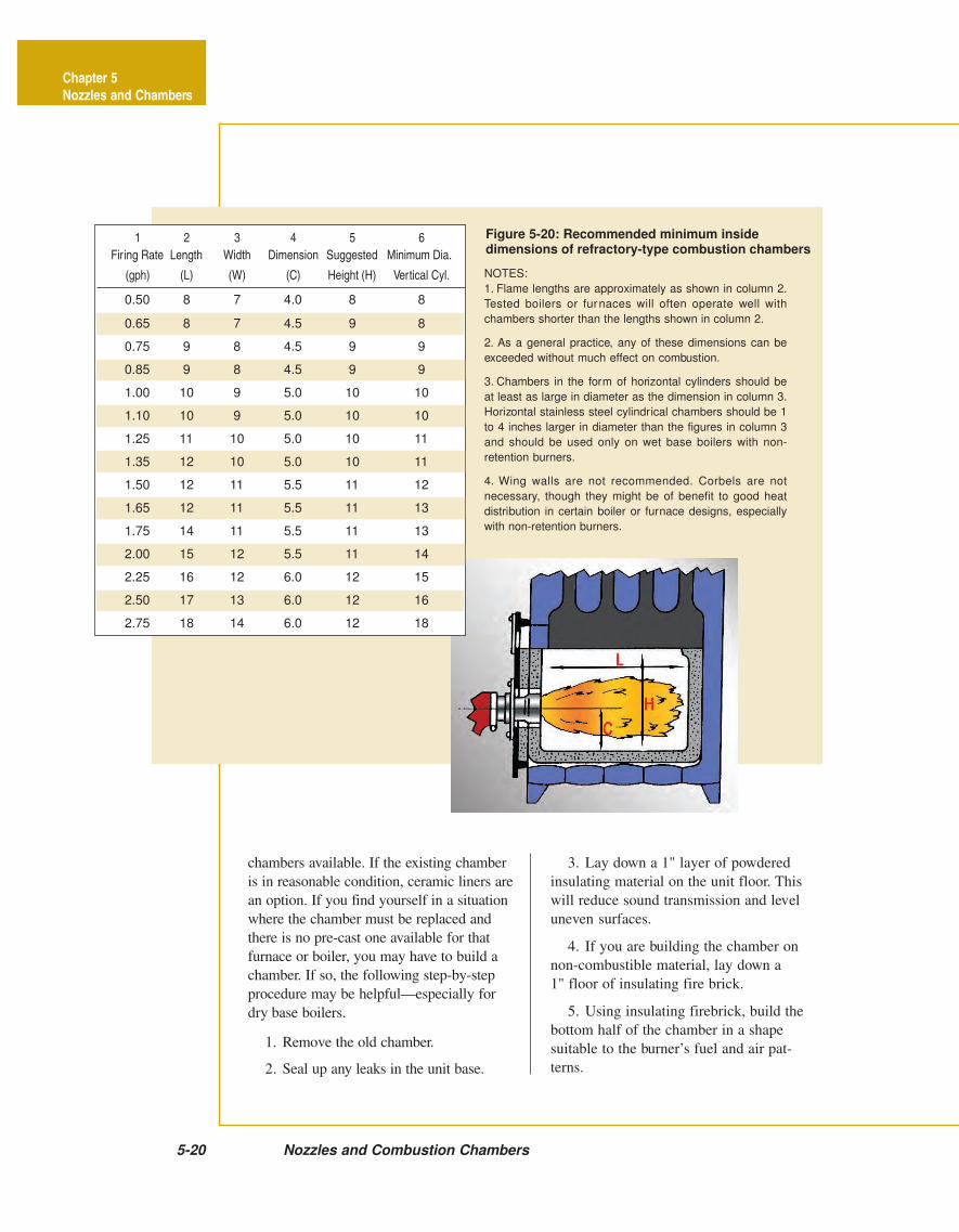
NOTES:
1. Flame lengths are approximately as shown in column 2.
Tested boilers or furnaces will often operate well with
chambers shorter than the lengths shown in column 2.
2. As a general practice, any of these dimensions can be
exceeded without much effect on combustion.
3. Chambers in the form of horizontal cylinders should be
at least as large in diameter as the dimension in column 3.
Horizontal stainless steel cylindrical chambers should be 1
to 4 inches larger in diameter than the figures in column 3
and should be used only on wet base boilers with non-
retention burners.
4. Wing walls are not recommended. Corbels are not
necessary, though they might be of benefit to good heat
distribution in certain boiler or furnace designs, especially
with non-retention burners.
Figure 5-20: Recommended minimum insidedimensions of refractory-type combustion chambers
1 2 3 4 5 6
Firing Rate Length Width Dimension Suggested Minimum Dia.
(gph) (L) (W) (C) Height (H) Vertical Cyl.
0.50 8 7 4.0 8 8
0.65 8 7 4.5 9 8
0.75 9 8 4.5 9 9
0.85 9 8 4.5 9 9
1.00 10 9 5.0 10 10
1.10 10 9 5.0 10 10
1.25 11 10 5.0 10 11
1.35 12 10 5.0 10 11
1.50 12 11 5.5 11 12
1.65 12 11 5.5 11 13
1.75 14 11 5.5 11 13
2.00 15 12 5.5 11 14
2.25 16 12 6.0 12 15
2.50 17 13 6.0 12 16
2.75 18 14 6.0 12 18
Chapter 5
Nozzles and Chambers
chambers available. If the existing chamber
is in reasonable condition, ceramic liners are
an option. If you find yourself in a situation
where the chamber must be replaced and
there is no pre-cast one available for that
furnace or boiler, you may have to build a
chamber. If so, the following step-by-step
procedure may be helpful—especially for
dry base boilers.
1. Remove the old chamber.
2. Seal up any leaks in the unit base.
3. Lay down a 1" layer of powdered
insulating material on the unit floor. This
will reduce sound transmission and level
uneven surfaces.
4. If you are building the chamber on
non-combustible material, lay down a
1" floor of insulating fire brick.
5. Using insulating firebrick, build the
bottom half of the chamber in a shape
suitable to the burner’s fuel and air pat-
terns.
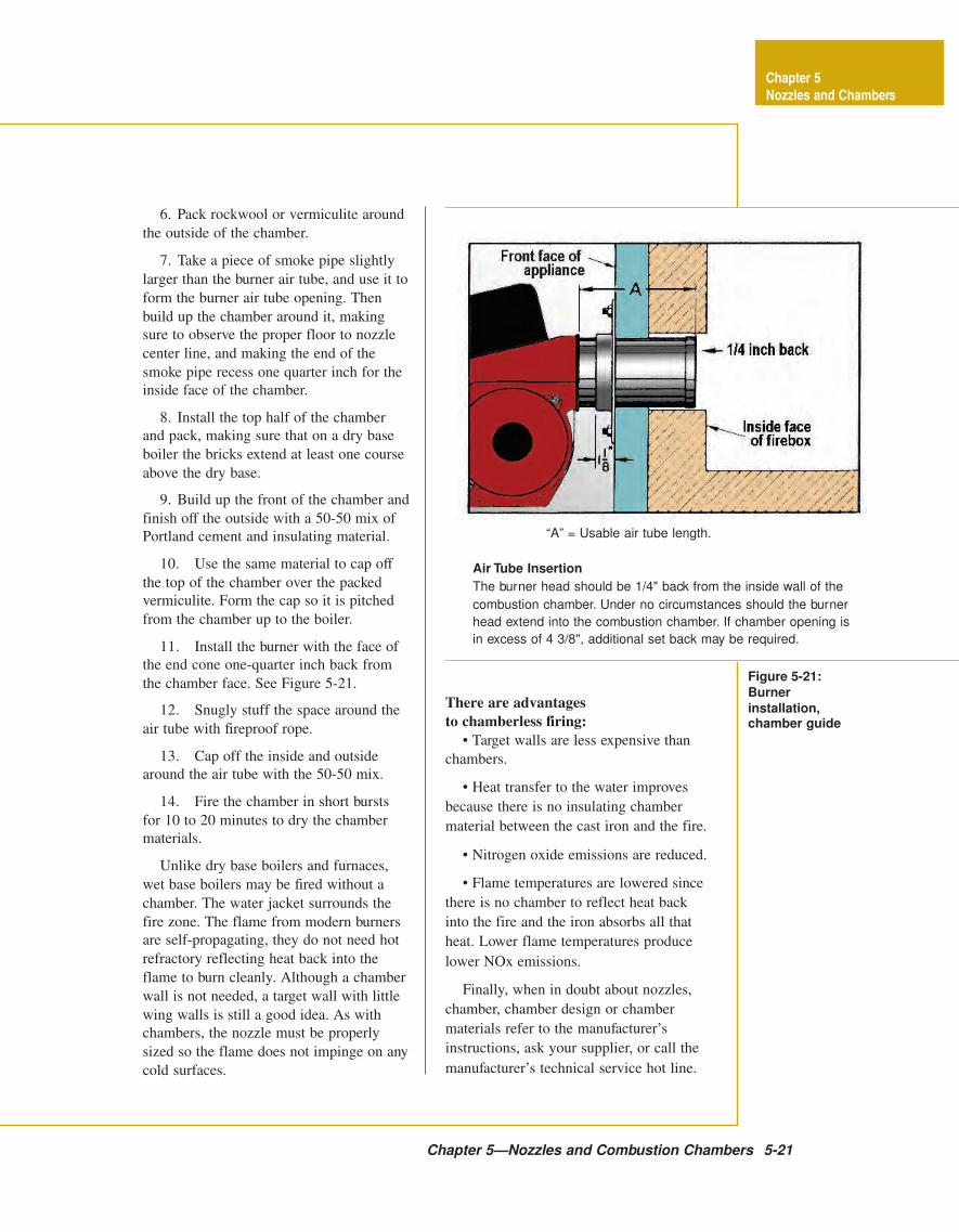
Figure 5-21:
Burner
installation,chamber guide
Chapter 5—Nozzles and Combustion Chambers 5-21
Chapter 5
Nozzles and Chambers
“A” = Usable air tube length.
Air Tube Insertion
The burner head should be 1/4" back from the inside wall of the
combustion chamber. Under no circumstances should the burner
head extend into the combustion chamber. If chamber opening is
in excess of 4 3/8", additional set back may be required.
6. Pack rockwool or vermiculite around
the outside of the chamber.
7. Take a piece of smoke pipe slightly
larger than the burner air tube, and use it to
form the burner air tube opening. Then
build up the chamber around it, making
sure to observe the proper floor to nozzle
center line, and making the end of the
smoke pipe recess one quarter inch for the
inside face of the chamber.
8. Install the top half of the chamber
and pack, making sure that on a dry base
boiler the bricks extend at least one course
above the dry base.
9. Build up the front of the chamber and
finish off the outside with a 50-50 mix of
Portland cement and insulating material.
10. Use the same material to cap off
the top of the chamber over the packed
vermiculite. Form the cap so it is pitched
from the chamber up to the boiler.
11. Install the burner with the face of
the end cone one-quarter inch back from
the chamber face. See Figure 5-21.
12. Snugly stuff the space around the
air tube with fireproof rope.
13. Cap off the inside and outside
around the air tube with the 50-50 mix.
14. Fire the chamber in short bursts
for 10 to 20 minutes to dry the chamber
materials.
Unlike dry base boilers and furnaces,
wet base boilers may be fired without a
chamber. The water jacket surrounds the
fire zone. The flame from modern burners
are self-propagating, they do not need hot
refractory reflecting heat back into the
flame to burn cleanly. Although a chamber
wall is not needed, a target wall with little
wing walls is still a good idea. As with
chambers, the nozzle must be properly
sized so the flame does not impinge on any
cold surfaces.
There are advantages
to chamberless firing:
• Target walls are less expensive than
chambers.
• Heat transfer to the water improves
because there is no insulating chamber
material between the cast iron and the fire.
• Nitrogen oxide emissions are reduced.
• Flame temperatures are lowered since
there is no chamber to reflect heat back
into the fire and the iron absorbs all that
heat. Lower flame temperatures produce
lower NOx emissions.
Finally, when in doubt about nozzles,
chamber, chamber design or chamber
materials refer to the manufacturer’s
instructions, ask your supplier, or call the
manufacturer’s technical service hot line.