Embed Size (px)
Citation preview
Pag.1
Novumax H₂R Manual for installation, use and maintanance
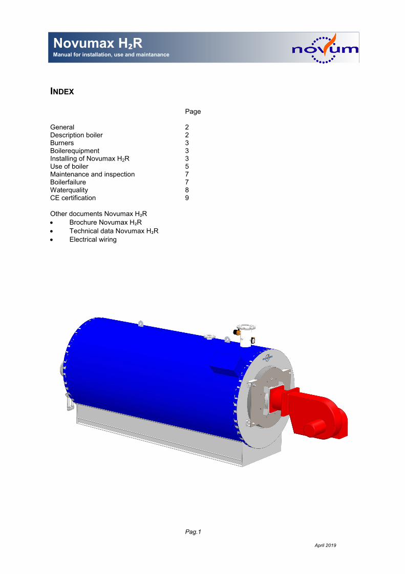
INDEX Page General 2 Description boiler 2 Burners 3 Boilerequipment 3 Installing of Novumax H2R 3 Use of boiler 5 Maintenance and inspection 7 Boilerfailure 7 Waterquality 8 CE certification 9
Other documents Novumax H₂R
• Brochure Novumax H₂R
• Technical data Novumax H₂R
• Electrical wiring
April 2019
Pag.2
Novumax H₂R Manual for installation, use and maintanance
ASSEMBLY AND OPERATING INSTRUCTIONS General This requirement provides an overview of the key points for the installation, assembly, operation and
maintenance of the boiler type Novumax H₂R. The prescriptions in this document should be followed
strictly. The data published in this technical information is based on the most recent information. This informa-tion is provided subject to subsequent changes. Novum reserves the right to change boiler type No-
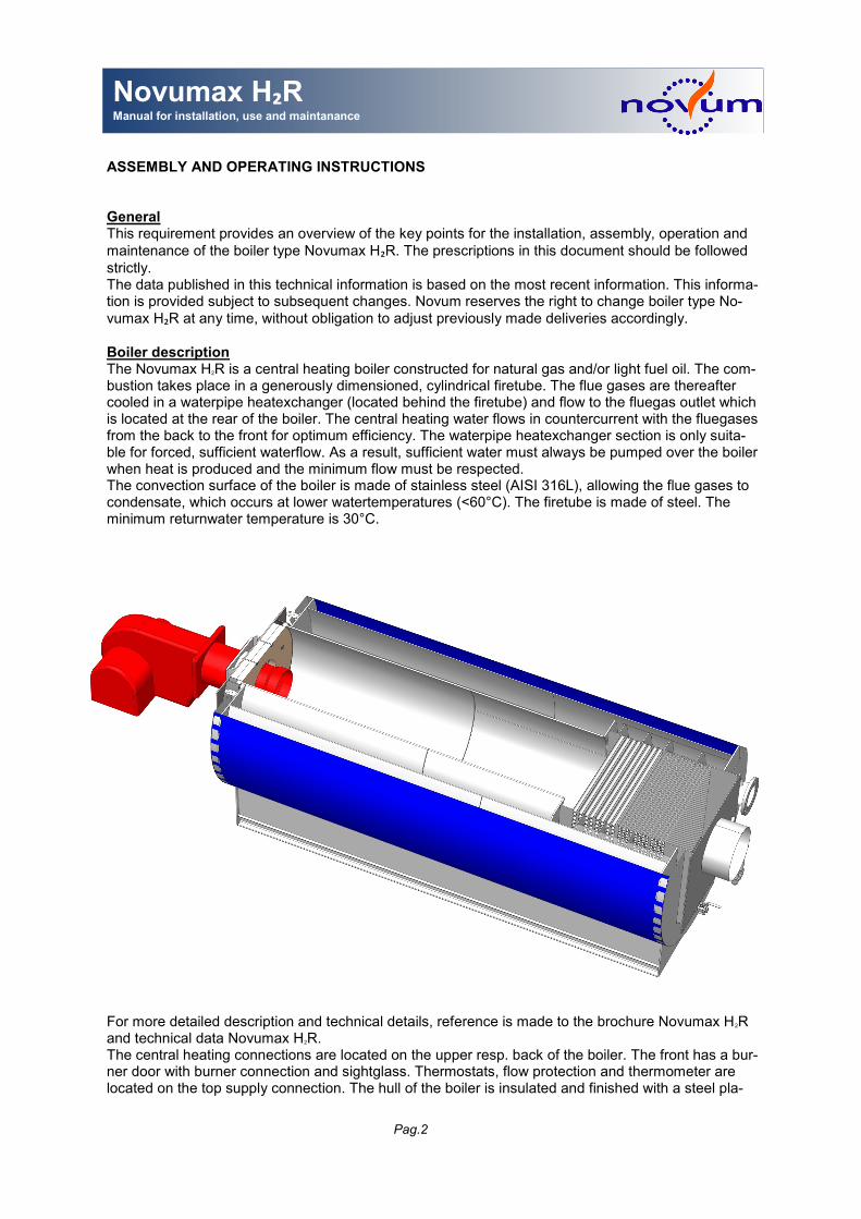
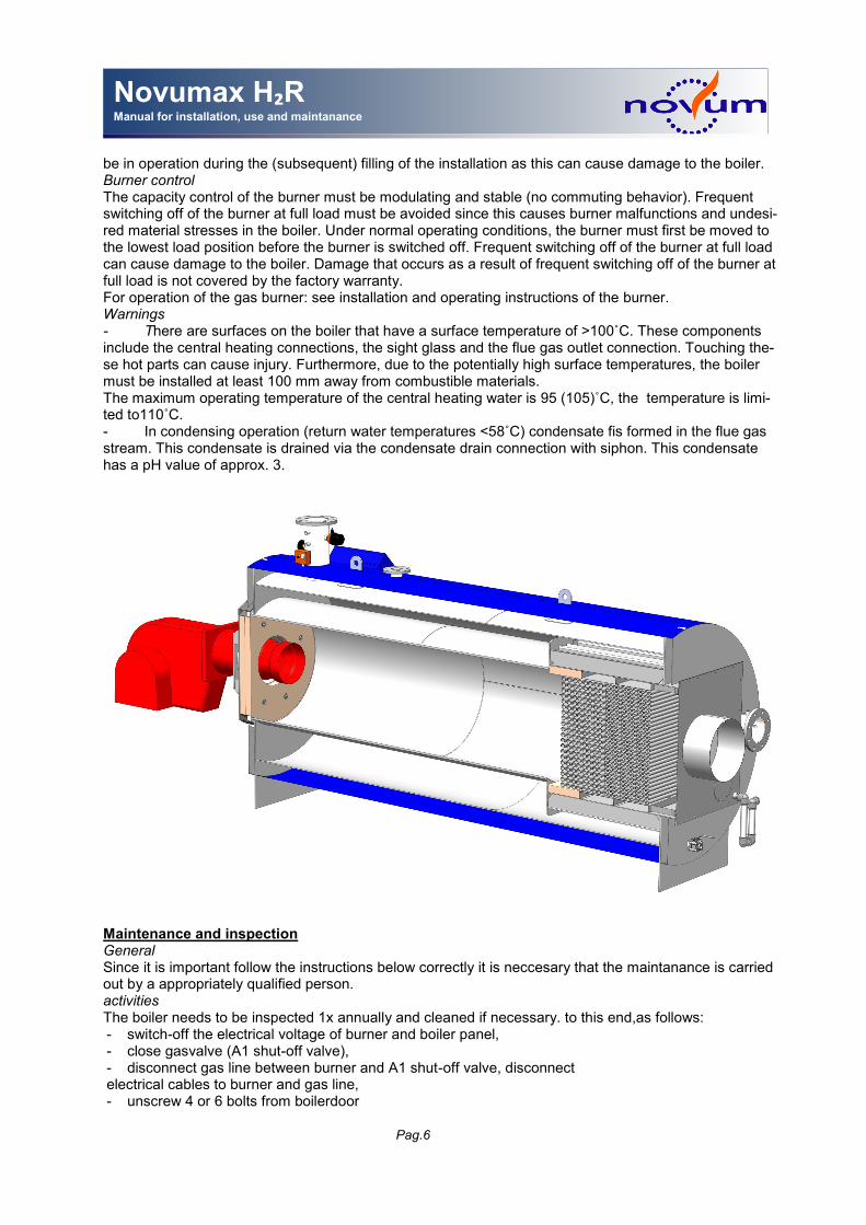
vumax H₂R at any time, without obligation to adjust previously made deliveries accordingly. Boiler description The Novumax H2R is a central heating boiler constructed for natural gas and/or light fuel oil. The com-bustion takes place in a generously dimensioned, cylindrical firetube. The flue gases are thereafter cooled in a waterpipe heatexchanger (located behind the firetube) and flow to the fluegas outlet which is located at the rear of the boiler. The central heating water flows in countercurrent with the fluegases from the back to the front for optimum efficiency. The waterpipe heatexchanger section is only suita-ble for forced, sufficient waterflow. As a result, sufficient water must always be pumped over the boiler when heat is produced and the minimum flow must be respected. The convection surface of the boiler is made of stainless steel (AISI 316L), allowing the flue gases to condensate, which occurs at lower watertemperatures (<60°C). The firetube is made of steel. The minimum returnwater temperature is 30°C.
For more detailed description and technical details, reference is made to the brochure Novumax H2R and technical data Novumax H2R. The central heating connections are located on the upper resp. back of the boiler. The front has a bur-ner door with burner connection and sightglass. Thermostats, flow protection and thermometer are located on the top supply connection. The hull of the boiler is insulated and finished with a steel pla-
Pag.3
Novumax H₂R Manual for installation, use and maintanance
ting painted in blue. The boiler meets the following essential requirements: GAR 2016/426 EN 60335-2-102: 2016-11-08 EN 301-1 - Part 1 EN 303-3 - Part 3 Burners The boiler is suitable for sliding high-low or modulated regulated gas or gas/oil burners (light, low-sulfur oil according to EN95). The burner must comply with the legal standards and be tested according to EN 676. The burner must be switched on and off at a low load position (<30% of nominal boiler capaci-ty). Boiler The following equipment is mounted on the boiler's supply connection: 1 combined maximum thermostat (110˚C) / on-off thermostat fabr. Siemens type RAZ –ST.030FP-J
(95˚C). or 1 maximum thermostat fabr. Siemens type RAK-ST.030 FP (110˚C) and 1 control thermostat fabr. Sie-
mens type RAK-TR1000B (95˚C) or 1 control thermostat fabr. Siemens type RAK-TW1200B (105˚C). The setting of this last thermostat is sealed and may not be changed.
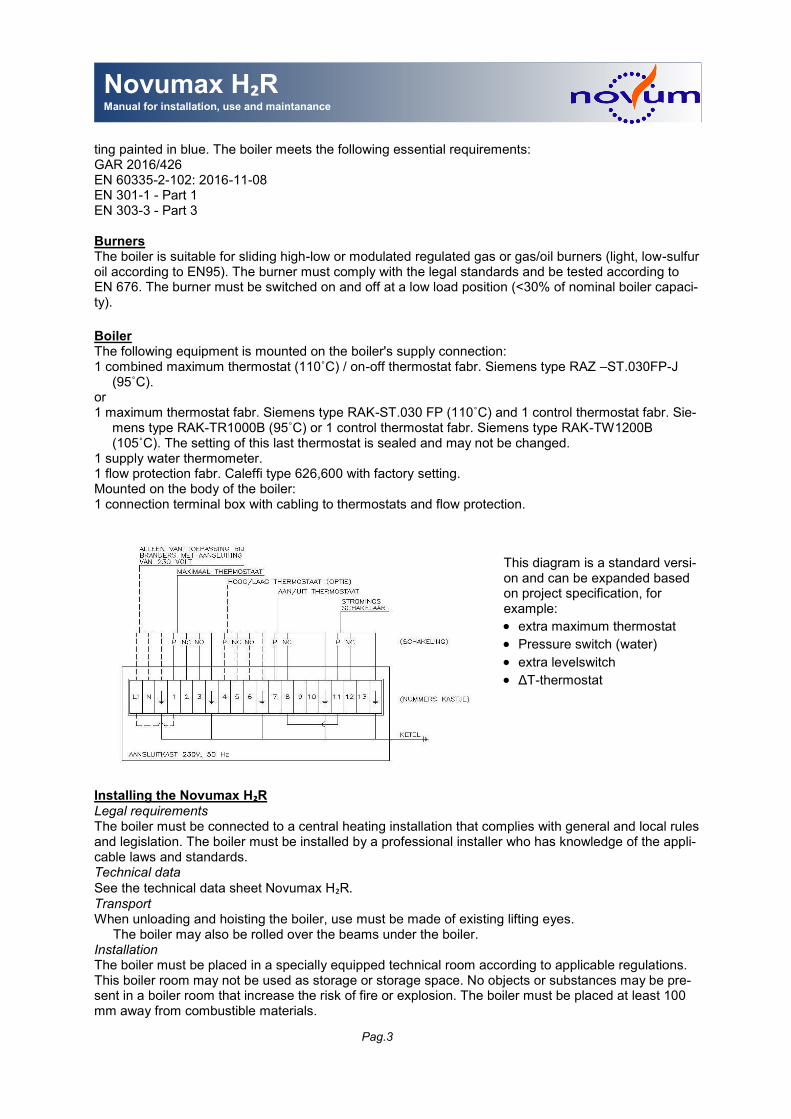
1 supply water thermometer. 1 flow protection fabr. Caleffi type 626,600 with factory setting. Mounted on the body of the boiler: 1 connection terminal box with cabling to thermostats and flow protection.
Installing the Novumax H₂R Legal requirements The boiler must be connected to a central heating installation that complies with general and local rules and legislation. The boiler must be installed by a professional installer who has knowledge of the appli-cable laws and standards. Technical data See the technical data sheet Novumax H₂R. Transport When unloading and hoisting the boiler, use must be made of existing lifting eyes.
The boiler may also be rolled over the beams under the boiler. Installation The boiler must be placed in a specially equipped technical room according to applicable regulations. This boiler room may not be used as storage or storage space. No objects or substances may be pre-sent in a boiler room that increase the risk of fire or explosion. The boiler must be placed at least 100 mm away from combustible materials.
This diagram is a standard versi-on and can be expanded based on project specification, for example:
• extra maximum thermostat
• Pressure switch (water)
• extra levelswitch
• ΔT-thermostat
Pag.4
Novumax H₂R Manual for installation, use and maintanance
The boiler can be placed on the floor without further provisions. The boiler support frame does not heat up during boiler operation. There must be sufficient room for maintenance and inspection during instal-
lation in the boiler room. See technical data sheet Novumax H₂R. The installation floor must be level.
The boiler room must be kept frost-free at all times. Supply and return pipes The connection dimensions for supply and return pipes are listed on the technical data sheet Novumax
H₂R. Before the installation is connected to the boiler, the central heating pipes must be thoroughly
cleaned internally. The supply and return lines must be mounted on the boiler without forces. It must be possible to shut off the boiler from the installation pipes by means of shut-off valves. Safety valve In accordance with regulation, install a safety valve on the designated connection on the boiler. The adjustment value of the safety valve must not exceed the pressure stated on the boiler nameplate. The blow-off capacity in kW at the adjusted value (pressure) must be greater than the maximum boiler ca-pacity. Pressure gauge Within the valves of the boiler, a pressure gauge must be fitted on which the boiler pressure can be read. Expansion vessel For collecting the thermal expansion of the water in the boiler, the boiler must be connected to an ex-pansion vessel with sufficient useful capacity (connection to the return line, within the boiler valves). To determine the useful content, use must be made of the water-side content of the boiler as stated in
technical data sheet NovumaxH₂R. The expansion pipe (connection between expansion vessel and
boiler) must be dimensioned in accordance with the connectionof the expansion vessel. If the expansi-on vessel is connectable to the boiler, the relevant valve must be designed in such a way that closing can only be done with tools or that the valve is automatically opened during mounting of the vessel. Note: In addition to this expansion vessel described, expansion vessels or vending machines are almost always required for the installation section. Cover flue gas inspection The rear of the boiler is equipped with a dismountable flue gas plate. The flue gas outlet connection is fitted on this flue gas plate. Since it must be possible to remove this flue gas plate for service purposes, the flue gas discharge connection must be dismantled to be connected to the flue gas discharge chan-nel. For normal maintenance and inspection work, however, it is sufficient to use the smaller lid in the flue gas plate. Both the flue gas plate and the inspection cover are sealed with a gasket made of teflon tape, bolts and nuts. Condensate/ siphon On the underside of the flue gas discharge cover there is a condensate drain sock (¾” or 1 ¼", depen-ding on the boiler type), which is equipped with a siphon. This trap must be connected to a drain pipe made of stainless steel, plastic or copper. This pipe must be laid down with a slope. The pipe must be equipped with an open funnel in the immediate vicinity of the siphon, such that no condensation water remains in the boiler when the drain pipe is clogged. The trap is made of stainless steel pipe nipples and 90˚ elbow pieces. Since these are all fitted connections, dismantling, cleaning and assembly is easy to carry out. Filling and draining valve At the bottom, on the rear of the boiler is a filling and draining valve ¾ ”. The boiler is almost completely emptied by draining. Firebox pressure There is a measuring nipple on the front door on which the firebox pressure can be measured. Make sure that this measuring nipple is normally closed. Flue gas outlet The horizontal stub of the flue gas outlet connection must be connected to a flue gas outlet channel made of high-quality corrosion-resistant material. This type of channel or duct system is considered to be a constructional device and must be CE marked according to the European Construction Products Directive (specifically EN 1856-1 and EN 1856-2) and to comply with the 2012 Building Decree. Fur-thermore, the following regulations apply: GAR (EU) 2016/426 (March 9, 2016), nuisance provisions in the General Local Regulation, emissions from combustion plants in the Environmental Management Act and the Activities Decree and Neighboring Law (Civil Code). The flue gas outlet must meet the fol-
Pag.5
Novumax H₂R Manual for installation, use and maintanance
lowing characteristics in accordance with EN1856-1: Temperature class: T120 Pressure class: H1 Condensate resistance: W Corrosion resistance: Vm Material specification: L50150, L40150fireformation Resistant to chimneydue to soot; the distance between the duct and combustible material in the envi-
ronment must be at least 100 mm (G100) The design and construction of a flue gas outlet must also meet the following conditions: The flue gas outlet must be insulated against the risk of contact. Angled connections may not be used (minimum 90˚ bends with 3 segments). Connection channels
must be designed to be flow-friendly, with as few bends as possible, sharp edges etc. Multiple bends in succession must be avoided. An unfavorable channel loop resp. inlet and outlet connecti-ons can negatively influence the proper functioning of boiler / burner combinations.
Thermal expansions of duct sections must be taken into account. Condensation that develops in the canal, or rainwater, must be drained to the sewer system at the lo-
west points. It is allowed to let all the condensate flow back to the boiler and to make use of the drain facility in the boiler's smoke box.
The back pressure that arises in the duct as a result of the burner installation operating (at full load) must not exceed the maximum back pressure of the flue gas discharge system. See for this techni-
cal data Novumax H₂R. The calculation should be based on a flue gas quantity as stated in this
sheet in kg/hr and a maximum flue gas temperature of 120˚C. The flue gas outlet connection of the boiler is equipped with a ½" connection with plug. This connection
can be used for measurements on the flue gas flow. Combustion air The combustion air that is sucked in by the burner must reasonably be dust-free. Furthermore, it is of great importance that no foreign substances can be drawn in, including, for example, hydrocarbons and halogen compounds. The required amount of combustion air in nm³/ hr is approximately 10-12 ti-mes the gas consumption in nm³/ hr. For the necessary provisions for air supply for combustion, as well as the required ventilation of the combustion room, we refer to local regulations. Burner For installation of the gas burner: see installation and operating instructions of the burnermanufactorer. Boiler use General As failure to properly follow the instructions stated below can cause danger, it is important that the ne-cessary work is carried out by a competent person. Start-up For start-up has to be checked that: - the boiler and the system to be completely filled with water, - the boiler and the heating system are free of air - the measuring nipple on the front door and the connecting sock on the flue gas lid is properly closed - the burner is mounted according to regulations - the boilerdoor is properly closed - the flue gas outlet is properly mounted and there are no leaks. - the supply and return valves and the gas tap are open, - the circulation pump is functioning properly and the required flow is between the specified minimum
and maximum value. - the thermostats are set to the correct values and / or the external control functions properly, - the installation pressure is between the minimum and maximum value (note the influence of the
head of the circulation pump) Heating up and operation of boiler Boiler By switching on the burner put into operation. Follow the instructions of the burner supplier before com-missioning the burner. After commissioning, check all water-side and flue-gas side gaskets for leaks. After firing up the installation, check the flow over the boiler and the installation pressures. If the instal-lation needs to be refilled after commissioning, venting must also be carried out. The burner must not
Pag.6
Novumax H₂R Manual for installation, use and maintanance
be in operation during the (subsequent) filling of the installation as this can cause damage to the boiler. Burner control The capacity control of the burner must be modulating and stable (no commuting behavior). Frequent switching off of the burner at full load must be avoided since this causes burner malfunctions and undesi-red material stresses in the boiler. Under normal operating conditions, the burner must first be moved to the lowest load position before the burner is switched off. Frequent switching off of the burner at full load can cause damage to the boiler. Damage that occurs as a result of frequent switching off of the burner at full load is not covered by the factory warranty. For operation of the gas burner: see installation and operating instructions of the burner. Warnings - There are surfaces on the boiler that have a surface temperature of >100˚C. These components include the central heating connections, the sight glass and the flue gas outlet connection. Touching the-se hot parts can cause injury. Furthermore, due to the potentially high surface temperatures, the boiler must be installed at least 100 mm away from combustible materials. The maximum operating temperature of the central heating water is 95 (105)˚C, the temperature is limi-ted to110˚C. - In condensing operation (return water temperatures <58˚C) condensate fis formed in the flue gas stream. This condensate is drained via the condensate drain connection with siphon. This condensate has a pH value of approx. 3.
Maintenance and inspection General Since it is important follow the instructions below correctly it is neccesary that the maintanance is carried out by a appropriately qualified person. activities The boiler needs to be inspected 1x annually and cleaned if necessary. to this end,as follows: - switch-off the electrical voltage of burner and boiler panel, - close gasvalve (A1 shut-off valve), - disconnect gas line between burner and A1 shut-off valve, disconnect electrical cables to burner and gas line, - unscrew 4 or 6 bolts from boilerdoor
Pag.7
Novumax H₂R Manual for installation, use and maintanance
- open boilerdoor - inspect the firetube and heat exchanger, - if necessary the fire and heat exchanger clean with a brush. - inspect the heat-resistant cover of the burner door and the gasket of the burner plate. - disassemble the inspection cover in the rear flue gas plate. - inspect the heat exchanger on the rear, as well as the condensate drain with siphon. Clean if ne-
cessary. - if the ceramic filler panels and / or the stainless steel filler panels located between the heat ex-
changer and boiler wall are damaged, they must be replaced. The flue gas plate must be comple-tely dismantled for this purpose. New panels can be ordered from Novum.
- assembly of disassembled parts in reverse order. - check the gaskets present and replace if necessary. The required packing material can be or-
dered from Novum. Level / flow protectionflow switch The flow switch mounted on the supply connection of the boiler also serves as level protection. Twice a year, a functional check must be made on the proper functioning of the flow switch. This is done by switching off the circulation pump or closing a boiler valve during pre-rinsing of the burner. The bur-ner must switch off immediately. If this is not the case, the boiler no longer needs to be put into ope-ration before the proper functioning is restored. The correct type of flow switch can be ordered from Machinefabriek Novum. The flow switches are set at the factory with regard to the correct switching point. The switches are equipped with 2 sealed settings. Both settings may not be adjusted under any circumstances. Burner For maintenance of the gas burner: see installation and operating instructions of the burner. Boiler malfunctions Maximum temperature.
Can be reset using the push button on the thermostat and the push button on the boiler panel. Check the boiler control (GBS control and on / off thermostat on the boiler) as well as the water circulation over the boiler. Notify the installer in the event of re-locking.
Flow protection. Check whether there is sufficient water flow through the boiler (see technical data table). Check whether the pressure in the installation is high enough. If the pre-pressure is too low, vapor can form on the suction side of a circulation pump, as a result of which the flow is completely or parti-ally eliminated. Check whether the installation has been sufficiently vented. If the boiler circulation pump draws in air, the flow can be completely or partially canceled.
Water quality Special attention must be paid to the water management of the central heating system. Water with a too high hardness leads to scaling and sludge formation, especially on the hottest parts of the heating surface of the boiler. This creates a high risk of defects. Furthermore, due to a too high oxygen con-centration in the water, a corrosion process can occur in boiler and pipes with associated adverse consequences. Damage that occurs as a result of poor water quality, sludge and boiler deposits and / or corrosion is not covered by the factory warranty. The amount of freshly introduced water (Vtotal) consists of the amount required for a first filling (installation content) and a quantity of after-supplementation. Post-supplementation will take place in the future, partly as a result of work on the installation, bleeding, etc. The amount of post-supplementation is of course unknown in advance. Vtotal may not exceed Vmax .
Vmax, it follows from: Vmax(m³) = 0.0313 x Q(kW)/ Ca (HCO3)2 (mol/m³)
Here,is Qthe power in kW boiler
Ca (HCO3)2, the hardness in mol / m³ (1 mol / m³ D = 5.6 °) If Vmax has been reached, must be made further supplementation and / or filling with deionized water (about 0.1 °D). An amount of scale (scale) has now formed on the VO of the boiler; further growth is
Pag.8
Novumax H₂R Manual for installation, use and maintanance
not allowed anymore. In a multi-boiler installation, it is not self-evident that the total boiler capacity for Q is entered in the above formula. When commissioning new installations, it often happens that only one of the new boilers temporarily supplies heat. In a short time (1 to 3 weeks) a large part of the hardness present in the fresh water can settle in this boiler. It is therefore wise to calculate with the smallest boiler capacity. As it is not known in advance how much water will be added over time, it is advisable to provide a softening installation when designing a new installation. If additional water is added that has a different hardness than the water that was previously filled or supplemented, this must be taken into account. To meet the condition of Vmax , the installation must be topped up from a central point and the quan-tities must be registered using a water meter. When replacing boilers in existing installations, the follo-wing must also be observed: the sludge and boiler deposits, as well as corrosion products present in the existing pipeline network, can end up in the newly installed boiler and cause serious damage. Therefore, when replacing a boiler in an existing installation, filtering, thorough rinsing, thorough clea-ning of the installation and appropriate water treatment is required. If necessary, consult a specialized company for this. The water quality must be checked periodically (1 to 2 times a year) for the values below. These mea-surements must be kept in a logbook as well as the amounts of supplemented water and the hard-ness of the supplemented water. pH 8.5 - 9.2 hardness <0.0107 mol / m3 (= 0.1 ° D) conductivity <600 µS / cm CL <150 mg / l Fe <0.2 mg / l Cu <0.1 mg / l Appearance clear, colorless and odorless Remarks: For very large central heating installations and hot water installations, it must be filled and supple-mented with demineralised and degassed water. Consult a specialized company for this. The use of source water or industrial water is discouraged. Addition of chemicals should only take place after written permission from Novum. CE certification
The boilers Novumax H₂R are CE marked. The category is B23, I₂ The electrical connection voltage is 230V, 50Hz Electrical protection rating IP20 The product identification number is 0063BQ3899
Pag.9
Novumax H₂R Manual for installation, use and maintanance
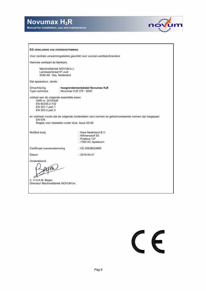
EG VERKLARING VAN OVEREENSTEMMING
Voor centrale verwarmingsketels geschikt voor voorzet-ventilatorbranders Hiermee verklaart de fabrikant, Machinefabriek NOVUM b.v. Landweerstraat 91 zuid 5349 AK Oss, Nederland Dat apparatuur, zijnde: Omschrijving : hoogrendementsketel Novumax H2R Type nummers : Novumax H2R 375 - 6000 voldoet aan de volgende essentiële eisen:
GAR nr. 2016/426 EN 60335-2-102 EN 301-1 part 1 EN 303-3 part 3
en verklaart voorts dat de volgende (onderdelen van) normen en geharmoniseerde normen zijn toegepast:
EN 676 Regels voor toestellen onder druk, Issue 05-09
Notified body : Kiwa Nederland B.V. : Wilmersdorf 50 : Postbus 137 : 7300 AC Apeldoorn Certificaat overeenstemming : CE 0063BQ3899 Datum : 2018-04-21 Ondertekend: Ir. V.H.A.M. Beijen Directeur Machinefabriek NOVUM bv.


![Novum Testamentum graece / [Hrsg.: Desiderius Erasmus]. 1547](https://img.pdfslide.us/doc/110x75/577d1fd41a28ab4e1e91686c/novum-testamentum-graece-hrsg-desiderius-erasmus-1547.jpg)