Embed Size (px)
Citation preview

Page 1
NOVOHALLRotary Sensortouchless technologytransmissive
Series RFC-4800
Special features• Touchless hall technology• Electrical range up to 360°• 2-part, mechanically decoupled• High protection class, IP67, IP6K9K• Resolution up to 14 Bit• Wear-free• Temperature range -40 °C to +125 °C• Single and multi-channel versions• Optimized for use in industrial and mobile applications• Interfaces: Voltage, current, SSI, incremental, CANopen, SPI, IO-Link• Customized versions
Applications• Manufacturing Engineering Textile machinery Packaging machinery Sheet metal and wire machinery• Automation technology• Medical engineering• Mobile working machines Industrial trucks Construction machinery Agricultural and forestry machinery• Marine applications

Drawings 3
Mechanical Data 4
Characteristics 5
Analog Versions for Industrial Applications
Technical Data 6
Ordering Specifications 7
Analog Versions for Mobile Applications
Technical Data 8
Ordering Specifications 9
Digital Versions
SSI 10
Incremental for Industrial an Mobile Applications 11
SPI 14
Ordering Specifications 15
Fieldbus Versions, IO-Link
CANopen 16
IO-Link 17
Ordering specifications 18
Accessories
Position Markers 19
M12 Connector System 22
Displays 25
Customized Versions
Connecting Options 26
Contents
Page 2 back to contents
Drawings
Page 3 back to contents
A-coded
Pin assignment M12 connector Pin assignment M12 connectorPin assignment M12 connector
A-codedA-coded
CAD data see www.novotechnik.de/en/download/cad-data/
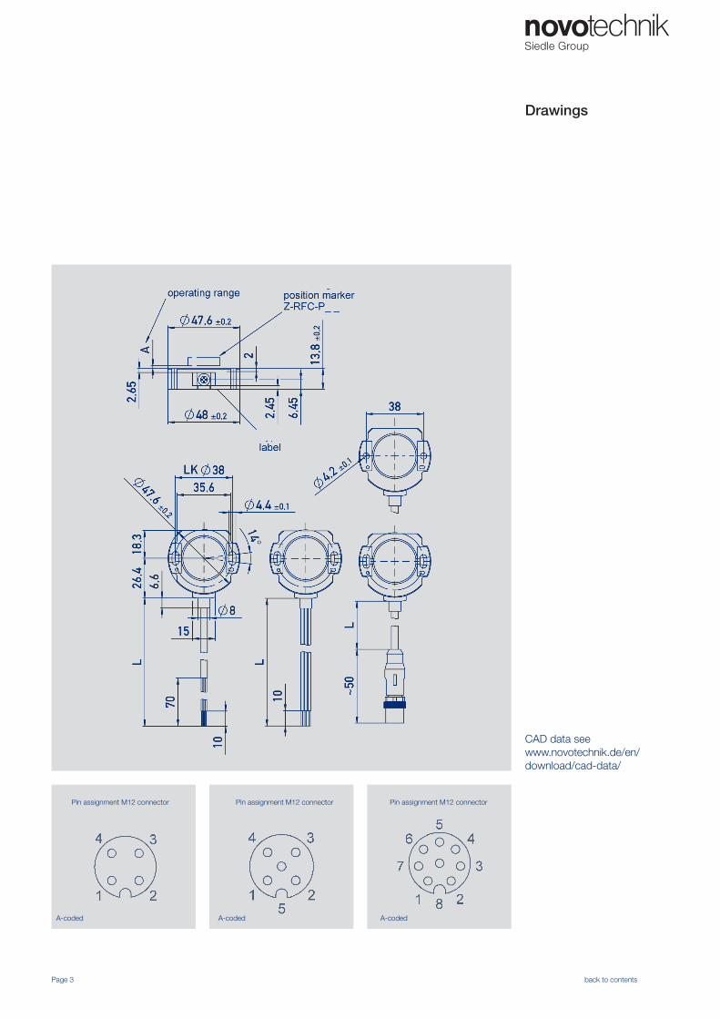
Mechanical Data
Dimensions see dimension drawing
Mounting with 2 lens flange head screws M4 (enclosed in delivery)
Fastening torque of mounting screws 250 Ncm
Mechanical travel 360 continuous °
Maximum operational speed mechanically unlimited
Weight (without connection) approx. 50 g
Vibration IEC 60068-2-6 5...2000Amax = 0.75amax = 20
Hzmmg
Shock IEC 60068-2-27 50 (6 ms) g
Life mechanically unlimited
Protection class DIN EN 60529 IP67 / IP68 / IP6K9K (not with M12 connector)
Page 4 back to contents
Mechanical Data
Description
Housing high grade, temperature resistant plastic
Electrical connection Cable 4x 0.14 mm², AWG 26, TPE, shielded (analog voltage / current CE)Cable 4x 0.14 mm², AWG 26, TPE, unshielded (analog voltage / current mobil)Cable 4x 0.5 mm², AWG 20, TPE, shielded (CANopen)Cable 5x 0.14 mm², AWG 26, PUR, shielded (SPI)Cable 8x 0.25 mm², AWG 24, TPE, shielded (SSI, Incremental, CANopen IN/OUT)Wire 0.5mm², AWG 20, PVC, (analog voltage / current, Incremental Open Collector)Connector M12x1, 4-pin / 5-pin / 8-pin with cable L=0.15 m
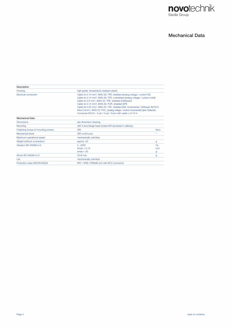
Characteristics
Page 5 back to contents
One channel, cw One channel, ccw
On request:Trapeze characteristic
Crossed characteristics, channel 1 cw On request:two channel, signal 2 = 0.5 x signal 1
On request:different gradients
On request:Parabolic characteristic
On request:2 staggered characteristics
Technical Data
Page 16 back to contents
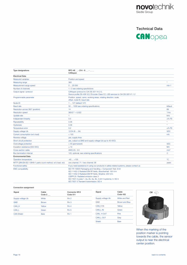
Type designations RFC-48 _ _- 214 - 6 _ _ - _ _ _ CANopen
Electrical Data
Measured variables Position and speed
Measuring range 360 °
Measurement range speed 0 ... 25 000 min-1
Number of channels 1 / 2 see ordering specifictions
Output signal / protocol CANopen protocol to CiA DS-301 V4.2.0, Device profile DS-406 V3.2 Encoder Class C2, LSS services to CiA DS-305 V1.1.2
Programmable parameter Position, speed, cams, working areas, rotating direction, scale, offset, node-ID, baud rate
Node-ID 1 ... 127 (default 127)
Baud rate 50 ... 1000 see ordering specifications kBaud
Resolution across 360° (position) 14 Bit
Resolution speed 360/214 ≈ 0,022 °/ms
Update rate 1 kHz
Independent linearity 0.5 ±% FS
Repeatability 0.36 °
Hysteresis 0.36 °
Temperature error 0.2 ±% FS
Supply voltage Ub 12/24 (8 ... 34) VDC
Current consumption (w/o load) < 100 mA
Reverse voltage yes, supply lines
Short circuit protection yes, output vs.GND and supply voltage Ub (up to 40 VDC)
Overvoltage protection < 45 (permanent) VDC
Insulation resistance (500 VDC) > 10 MΩ
Cross-section cable AWG 20, 0.5 mm2
Bus termination internal 120, optional, see ordering specifications Ω
Environmental Data
Operation temperature -40 ... +105 °C
MTTF (DIN EN ISO 13849-1 parts count method, w/o load, wc) one channel: 71 / two channel: 58 years
Functional safety If you need assistance in using our products in safety-related systems, please contact us
EMC compatibility ISO TR 10605 Packaging and Handling + Component Test: 8 kVISO 11452-2 Radiated EM RF fields, Absorberhall: 100 V/mISO 11452-5 Radiated EM RF fields, Stripline: 200 V/mCISPR 25 Radiated emission class 3ISO 7637-2 pulse 1, 2a, 2b, 3a, 3b, 4 (24 V systems), 5: SG 5ISO 7637-3 Transient transmission: SG 4
When the marking of theposition marker is pointingtowards the cable, the sensoroutput is near the electricalcenter position.
Connection assignment
Signal CableCode 2 _ _
Connector M12Code 511
Supply voltage Ub White Pin 2
GND Brown Pin 3
CAN_H Yellow Pin 4
CAN_L Green Pin 5
CAN Shield Bare Pin 1
Signal Cable Code 432
Supply voltage Ub White and Red
GND Brown and Blue
CAN_H IN Yellow
CAN_L IN Green
CAN_ H OUT Pink
CAN_L OUT Grey
Shield Bare
Technical Data
Seite 17 zurück zu Inhalt
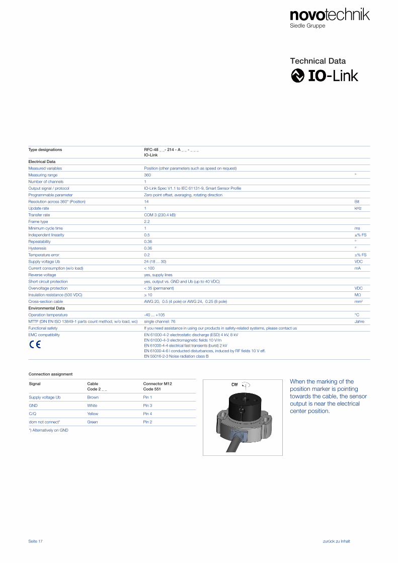
Type designations RFC-48 _ _- 214 - A _ _ - _ _ _ IO-Link
Electrical Data
Measured variables Position (other parameters such as speed on request)
Measuring range 360 °
Number of channels 1
Output signal / protocol IO-Link Spec V1.1 to IEC 61131-9, Smart Sensor Profile
Programmable parameter Zero point offset, averaging, rotating direction
Resolution across 360° (Position) 14 Bit
Update rate 1 kHz
Transfer rate COM 3 (230.4 kB)
Frame type 2.2
Minimum cycle time 1 ms
Independent linearity 0.5 ±% FS
Repeatability 0.36 °
Hysteresis 0.36 °
Temperature error 0.2 ±% FS
Supply voltage Ub 24 (18 ... 30) VDC
Current consumption (w/o load) < 100 mA
Reverse voltage yes, supply lines
Short circuit protection yes, output vs. GND and Ub (up to 40 VDC)
Overvoltage protection < 35 (permanent) VDC
Insulation resistance (500 VDC) > 10 MΩ
Cross-section cable AWG 20, 0.5 (4 pole) or AWG 24, 0.25 (8 pole) mm2
Environmental Data
Operation temperature -40 ... +105 °C
MTTF (DIN EN ISO 13849-1 parts count method, w/o load, wc) single channel: 76 Jahre
Functional safety If you need assistance in using our products in safety-related systems, please contact us
EMC compatibility EN 61000-4-2 electrostatic discharge (ESD) 4 kV, 8 kVEN 61000-4-3 electromagnetic fields 10 V/mEN 61000-4-4 electrical fast transients (burst) 2 kVEN 61000-4-6 l conducted disturbances, induced by RF fields 10 V eff.EN 55016-2-3 Noise radiation class B
When the marking of theposition marker is pointingtowards the cable, the sensoroutput is near the electricalcenter position.
Connection assignment
Signal CableCode 2 _ _
Connector M12Code 551
Supply voltage Ub Brown Pin 1
GND White Pin 3
C/Q Yellow Pin 4
dom not connect* Green Pin 2
*) Alternatively on GND
Seite 18 zurück zu Inhalt
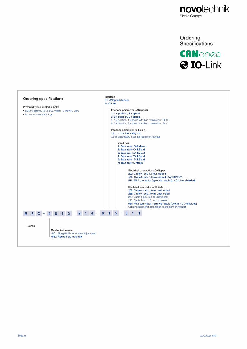
Ordering Specifications
– ––R 164122584CF 5
Interface6: CANopen InterfaceA: IO-Link
Baud rate1: Baud rate 1000 kBaud2: Baud rate 800 kBaud3: Baud rate 500 kBaud4: Baud rate 250 kBaud5: Baud rate 125 kBaud 7: Baud rate 50 kBaud
Interface parameter CANopen 6 _ _1: 1 x position, 1 x speed 2: 2 x position, 2 x speed5: 1 x position, 1 x speed with bus termination 120 Ω 6: 2 x position, 2 x speed with bus termination 120 Ω
Interface parameter IO-Link A _ _11: 1 x position, rising cwOther parameters (such as speed) on request
Series
Mechanical version4851: Elongated hole for easy adjustment 4852: Round hole mounting
– 15 1
Electrical connections CANopen202: Cable 4-pol. 1.0 m, shielded 432: Cable 8-pol., 1.0 m shielded (CAN IN/OUT)511: M12 connector 5-pin with cable (L = 0.15 m; shielded)
Elektrical connections IO-Link252: Cable 4-pol., 1.0 m, unshielded 256: Cable 4-pol., 3.0 m, unshielded260: Cable 4-pol., 5.0 m, unshielded270: Cable 4-pol., 10,. m, unshielded551: M12 connector 4-pin with cable (L=0.15 m, unshielded) Cable versions and assembled connectors on request
Ordering specifications
Preferred types printed in bold:
• Delivery time up to 25 pcs. within 10 working days
• No low volume surcharge
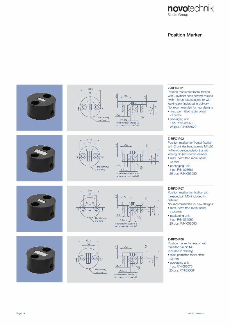
Z-RFC-P01Position marker for frontal fixation with 2 cylinder head screws M4x20 (with microencapsulation) or with locking pin (included in delivery).Not recommended for new designs.• max. permitted radial offset ±1.5 mm• packaging unit: 1 pc. P/N 005660 25 pcs. P/N 056079
Position Marker
Z-RFC-P02Position marker for frontal fixation with 2 cylinder head screws M4x20 (with microencapsulation) or with locking pin (included in delivery).• max. permitted radial offset ±3 mm• packaging unit: 1 pc. P/N 005661 25 pcs. P/N 056080
Z-RFC-P07Position marker for fixation with threaded pin M5 (included in delivery).Not recommended for new designs.• max. permitted radial offset ±1,5 mm• packaging unit: 1 pc. P/N 056069 25 pcs. P/N 056083
Z-RFC-P08Position marker for fixation with threaded pin pin M5 (included in delivery).• max. permitted radial offset ±3 mm• packaging unit: 1 pc. P/N 056070 25 pcs. P/N 056084
Page 19 back to contents

Z-RFC-P23Position marker for fixation with threaded pin M4(included in delivery)• max. permitted radial offset ±3 mm• packaging unit: 1 pc. P/N 056074 25 pcs. P/N 056085
Z-RFC-P30Position marker for frontal fixation with 2 fillister screws M3x8(included in delivery)screws• max. permitted radial offset ±1.5 mm• packaging unit: 1 pc. P/N 056086 25 pcs. P/N 056087
Position Marker
Page 20 back to contents
Z-RFC-P16Screw position marker M10 x 25 mm, similar DIN 933, A2, bare, magnet potted• max. permitted radial offset ±3 mm• packaging unit: 1 pc. P/N 104203 25 pcs. /P/N 104204
Z-RFC-P17Screw position marker M8 x 25 mm, similar DIN 933 / ISO 4017, A2, bare, magnet potted• max. permitted radial offset ±1,5 mm• packaging unit: 1 pc. P/N 104205 25 pcs. P/BN 104206
Position Marker
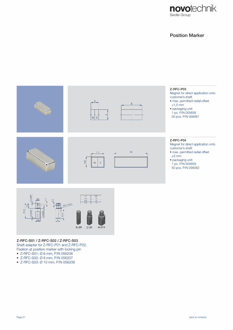
Z-RFC-P04Magnet for direct application onto customer’s shaft• max. permitted radial offset ±3 mm• packaging unit: 1 pc. P/N 005659 50 pcs. P/N 056082
Z-RFC-P03Magnet for direct application onto customer’s shaft• max. permitted radial offset ±1,5 mm• packaging unit: 1 pc. P/N 005658 50 pcs. P/N 056081
Page 21 back to contents
Z-RFC-S01 / Z-RFC-S02 / Z-RFC-S03Shaft adapter for Z-RFC-P01 and Z-RFC-P02.Fixation at position marker with locking pin• Z-RFC-S01: Ø 6 mm, P/N 056206 • Z-RFC-S02: Ø 8 mm, P/N 056207• Z-RFC-S03: Ø 10 mm, P/N 056208
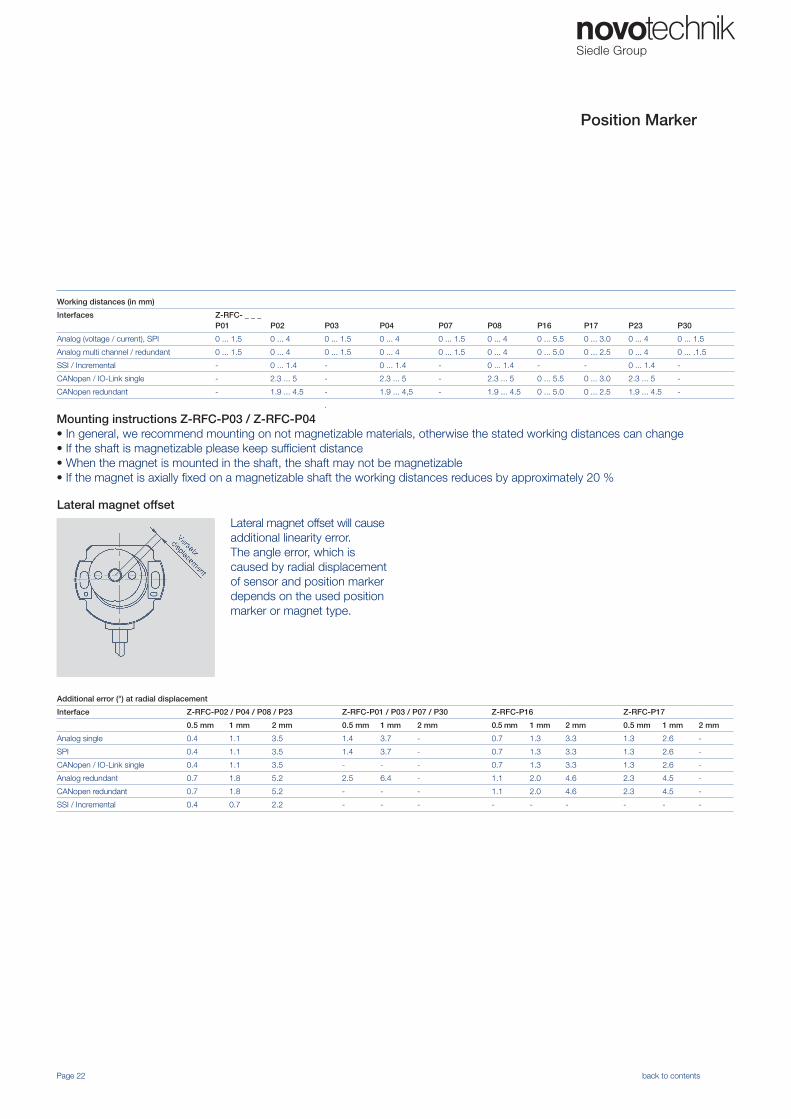
Lateral magnet offset will cause additional linearity error.The angle error, which is caused by radial displacement of sensor and position marker depends on the used position marker or magnet type.
Mounting instructions Z-RFC-P03 / Z-RFC-P04• In general, we recommend mounting on not magnetizable materials, otherwise the stated working distances can change• If the shaft is magnetizable please keep sufficient distance• When the magnet is mounted in the shaft, the shaft may not be magnetizable• If the magnet is axially fixed on a magnetizable shaft the working distances reduces by approximately 20 %
Position Marker
Page 22 back to contents
Working distances (in mm)
Interfaces Z-RFC- _ _ _P01 P02 P03 P04 P07 P08 P16 P17 P23 P30
Analog (voltage / current), SPI 0 ... 1.5 0 ... 4 0 ... 1.5 0 ... 4 0 ... 1.5 0 ... 4 0 ... 5.5 0 ... 3.0 0 ... 4 0 ... 1.5
Analog multi channel / redundant 0 ... 1.5 0 ... 4 0 ... 1.5 0 ... 4 0 ... 1.5 0 ... 4 0 ... 5.0 0 ... 2.5 0 ... 4 0 ... .1.5
SSI / Incremental - 0 ... 1.4 - 0 ... 1.4 - 0 ... 1.4 - - 0 ... 1.4 -
CANopen / IO-Link single - 2.3 ... 5 - 2.3 ... 5 - 2.3 ... 5 0 ... 5.5 0 ... 3.0 2.3 ... 5 -
CANopen redundant - 1.9 ... 4.5 - 1.9 ... 4,5 - 1.9 ... 4.5 0 ... 5.0 0 ... 2.5 1.9 ... 4.5 -
.
Additional error (°) at radial displacement
Interface Z-RFC-P02 / P04 / P08 / P23 Z-RFC-P01 / P03 / P07 / P30 Z-RFC-P16 Z-RFC-P17
0.5 mm 1 mm 2 mm 0.5 mm 1 mm 2 mm 0.5 mm 1 mm 2 mm 0.5 mm 1 mm 2 mm
Analog single 0.4 1.1 3.5 1.4 3.7 - 0.7 1.3 3.3 1.3 2.6 -
SPI 0.4 1.1 3.5 1.4 3.7 - 0.7 1.3 3.3 1.3 2.6 -
CANopen / IO-Link single 0.4 1.1 3.5 - - - 0.7 1.3 3.3 1.3 2.6 -
Analog redundant 0.7 1.8 5.2 2.5 6.4 - 1.1 2.0 4.6 2.3 4.5 -
CANopen redundant 0.7 1.8 5.2 - - - 1.1 2.0 4.6 2.3 4.5 -
SSI / Incremental 0.4 0.7 2.2 - - - - - - - - -
Lateral magnet offset
Pin assignment
Pin assignment
Pin assignment
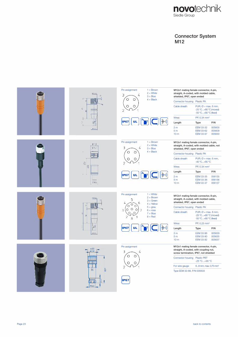
1 = Brown 2 = White3 = Blue 4 = Black
M12x1 mating female connector, 4-pin,straight, A-coded, with coupling nut,screw termination, IP67, not shielded
Connector housing Plastic PBT-25 °C...+90 °C
For wire gauge 6...8 mm, max. 0,75 mm2
Type EEM 33-88, P/N 005633
1 = Brown 2 = White3 = Blue 4 = Black
1 = White 2 = Brown3 = Green4 = Yellow5 = grau6 = rosa7 = Blue 8 = Red
Connector System M12
Pin assignment
Page 23 back to contents
M12x1 mating female connector, 4-pin,straight, A-coded, with molded cable,shielded, IP67, open ended
Connector housing Plastic PA
Cable sheath PUR; Ø = max. 6 mm,-25 °C...+80 °C (moved)-50 °C...+80 °C (fixed)
Wires PP, 0.34 mm2
Length Type P/N
2 m5 m10 m
EEM 33-32EEM 33-62EEM 33-97
005600005609005650
M12x1 mating female connector, 4-pin,straight, A-coded, with molded cable, notshielded, IP67, open ended
Connector housing Plastic PA
Cable sheath PUR; Ø = max. 6 mm,-40 °C...+85 °C
Wires PP, 0.34 mm2
Length Type P/N
2 m5 m10 m
EEM 33-35EEM 33-36EEM 33-37
056135056136056137
M12x1 mating female connector, 8-pin,straight, A-coded, with molded cable, shielded, IP67, open ended
Connector housing Plastic PA
Cable sheath PUR; Ø = max. 8 mm,-25 °C...+80 °C (moved)-50 °C...+80 °C (fixed)
Wires PP, 0.25 mm2
Length Type P/N
2 m5 m10 m
EEM 33-86EEM 33-90EEM 33-92
005629005635005637
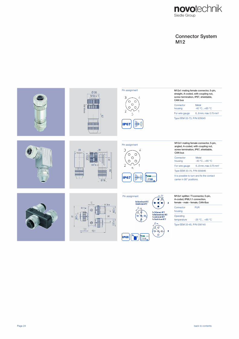
M12x1 mating female connector, 5-pin,straight, A-coded, with coupling nut,screw termination, IP67, shieldable, CAN bus
Connector housing
Metal-40 °C...+85 °C
For wire gauge 6...8 mm, max. 0.75 mm2
Type EEM 33-73, P/N 005645
Pin assignment
Page 24 back to contents
Pin assignment
M12x1 splitter / T-connector, 5-pin,A-coded, IP68,1:1 connection,female - male - female, CAN-Bus
Connector
housing
PUR
Operating
temperature -25 °C... +85 °C
Type EEM 33-45, P/N 056145
Pin assignment
Connector System M12
M12x1 mating female connector, 5-pin,angled, A-coded, with coupling nut,screw termination, IP67, shieldable, CAN bus
Connector housing
Metal-40 °C...+85 °C
For wire gauge 6...8 mm, max. 0.75 mm2
Type EEM 33-75, P/N 005646
It is possible to turn and fix the contact
carrier in 90° positions.
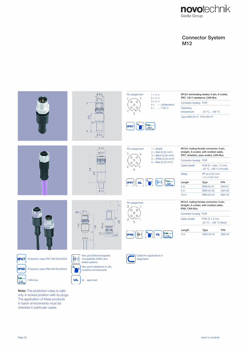
M12x1 terminating resistor, 5-pin, A-coded,IP67, 120 Ω resistance, CAN-Bus
Connector housing PUR
Operating
temperature -25 °C... +85 °C
Type EEM 33-47, P/N 056147
Pin assignment 1 = n. c.2 = n. c.3 = n. c.4 = 5 =
Widerstand 120 Ω
M12x1 mating female connector, 5-pin,straight, A-coded, with molded cable,IP67, shielded, open ended, CAN-Bus
Connector housing PUR
Cable sheath PUR Ø = max. 7.2 mm,-25 °C...+85 °C (moved)
Wiires PP 2x 0.25 mm2 + 2 x 0.34 mm2
Pin assignment 1 = Shield 2 = Red (0,34 mm2)3 = Black (0,34 mm2)4 = White (0,25 mm2)5 = Blue (0,25 mm2)
M12x1 mating female connector, 5-pin,straight, A-coded, with molded cable, IP68, CAN-Bus
Connector housing PUR
Cable sheath PUR; Ø 7.2 mm
-25 °C... +85 °C (fixed)
Pin assignment
Length Type P/N
2 m EEM 33-41 056141
5 m EEM 33-42 056142
10 m EEM 33-43 056143
Length Type P/N
5 m EEM 33-44 056144
Note: The protection class is validonly in locked position with its plugs.The application of these productsin harsh environments must bechecked in particular cases.
Protection class IP67 DIN EN 60529
UL - approved
Very good ElectromagneticCompatibility (EMC) andshield systems
Very good resistance to oils,coolants und lubricants
Suited for applications indragchains
Protection class IP68 DIN EN 60529
CAN-bus
Page 25 back to contents
Connector System M12
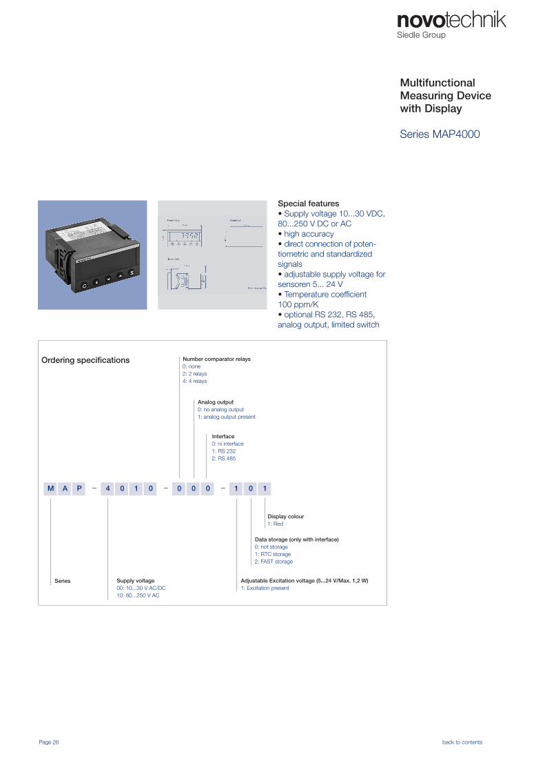
MultifunctionalMeasuring Devicewith Display
Series MAP4000
Special features• Supply voltage 10...30 VDC, 80...250 V DC or AC• high accuracy• direct connection of poten-tiometric and standardized signals• adjustable supply voltage for sensoren 5... 24 V• Temperature coefficient 100 ppm/K• optional RS 232, RS 485, analog output, limited switch
– ––M 010000104PA 1
Number comparator relays0: none2: 2 relays 4: 4 relays
Display colour1: Red
Data storage (only with interface)0: not storage1: RTC storage2: FAST storage
Analog output0: no analog output1: analog output present
Series Supply voltage00: 10...30 V AC/DC10: 80...250 V AC
Adjustable Excitation voltage (5...24 V/Max. 1,2 W)1: Excitation present
Ordering specifications
Interface0: ni interface1: RS 2322: RS 485
Page 26 back to contents
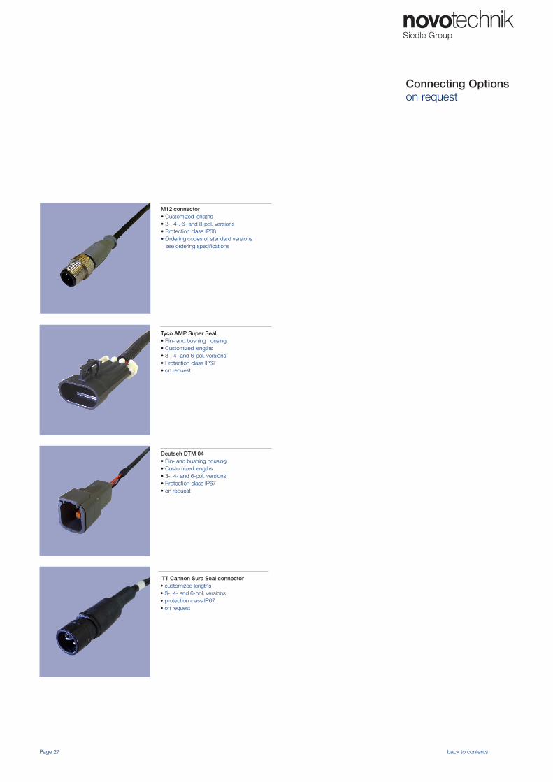
Connecting Optionson request
ITT Cannon Sure Seal connector• customized lengths • 3-, 4- and 6-pol. versions• protection class IP67• on request
Tyco AMP Super Seal• Pin- and bushing housing• Customized lengths• 3-, 4- and 6-pol. versions• Protection class IP67• on request
Deutsch DTM 04• Pin- and bushing housing• Customized lengths• 3-, 4- and 6-pol. versions• Protection class IP67• on request
Page 27 back to contents
M12 connector• Customized lengths • 3-, 4-, 6- and 8-pol. versions• Protection class IP68• Ordering codes of standard versions see ordering specifications
Page 28 back to contents
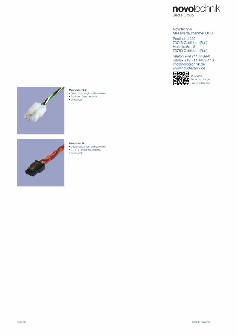
Molex Mini Fit• Customized length and lead wires• 3-, 4-, 6- and 8-pol. versions• on request
Molex Mini Fit jr.• Customized length and lead wires• 3-, 4- and 6-pol. versions• on request
NovotechnikMesswertaufnehmer OHG
Postfach 422073745 Ostfildern (Ruit)Horbstraße 1273760 Ostfildern (Ruit)
Telefon +49 711 4489-0Telefax +49 711 [email protected]
© 12/2015
Subject to change.
Printed in Germany.