Embed Size (px)
Citation preview

-. -
AD
TECHNICAL REPORT ARLCB-TR-82037
THERMAL WARNING DEVICE PROGRAM
155mm M185 HOWITZER M109A1/A2/A3 "
JOHN E. BROWER
DTICrELECTE3
JAN 3 1983.
NOVEMBER 1982 B 3"US ARMY ARMAMENT RESEARCH AND DEVELOPMENT COMMAND
LARGE CALIBER WEAPON SYSTEMS LABORATORYV . BENET WEAPONS LABORATORY.rWATERVLIET N.Y. 12189
APPROVED FOR PUBLIC RELEASE; DISTRIBUTION UNLIMITED S
82 12 14 003

- ..-- . AA
The findings in this-report are not to be construed as an official
* Department of the Armay position unless so designated by other author.-
* ized documents.
The use of trade name(s) and/or manufacture(q) does not consti-.
* tute an official indorsemuent or approval.
DISPOSITIM
*Destroy this report when itis nolonger needed. Do not return it
* to the originator.

SECURITY CLASSIFICATION OF THIS PAGE f5 Dete Mbnmre
REOMRT 19fTMPG READ fISTRUCTIONS,.E ORT CMENTATOB PAGE EFORE COMPLETuING FORM
.REPORT NUMBRF GOVT ACCESSION NO 3. RECIPIENT'S CATALOG NUMBER
ARLCB-TR-820374. TITLE (Am daWiue) S. TYPE OF REPORT & PERtOD COVEREDTHERMAL WARNING DEVICE PROGRAM155mm M185 HOWITZER M1O9AI/A2/A3 Final
4. PERFORMING ORG. REPORT NUMBER
7. AUTNORq') S. CONTRACT OR GRANT NUMUER(a)
John E. Browe,.
is 5 FORNl6 OGANIVAIOMN NAMI AND ADR, 10. PROGRAM ELEMENT PROJECT. TASKUtfgrmy esearch an Development Command AREA 4 WORK UNiT NUMBERS
Benet Weapons Laboratory, DRDAR-LCB-TL AMCMS No. 31111622230Watervliet, NY 12189 PRON No. 1A0204831A1A
II. CONTROLLING OFFICE NAME ANO ADDRESS 12. REPORT DATE
US Army Armament Research and Development Command November 1982Large Caliber Weapon Systems Laboratory 1s. NUMbER OF PAGESDover, NJ 07801 2314. MONITORING AGENCY NAME S ADDRE(IB&VI E t.brmn ContollbW Office) IS. SECURITY CLASS. (of thE report)
UNCLASS I FI EDIS&. DECL ASSI FI CATION/DOWNGRADING 1.
SCHEDULE,,
IS. DISTRIBUTION STATEMENT (of 1. ARe,*j
Approved for public release; distribution unlimited.
7::17. DISTRIBUTION STATEMENT (of 00 aba8eo, .tmed In Weak 20. it dflmt AVEm Report)
IS. SUPPLEMENTARY OTES"
IS. KEY WORDS (C.bm an ar" .* Dl, ulmmf and fdmd, D I. Week m=o)
Thermal Warning Device SlotPropelling Charge Fatigue LifeCook-Off Independent Design Review
I&2 AMSMRACT (ft m d 3 aus m aMndfsf by Wook ribnw)
A Product Improvement Program was undertaken to provide a thermal warningdevice to. measure the temperature of the M185 Howitzer tube forcing conearea from the tube outside diameter and provide a readout to the user at thebreech end. This would warn the gun crew when a dangerous temperature levelhad been attained, as well as permit a higher rate of fire than currentprocedures allow. (CONT'D ON REVERSE)
WX ,o,, 43 no-ow c. ,or .l R meaa m.,raJUM UNCLASSIFIED
SECURITY CLASSIFICATION OF THIS PAGE (Im Data Entered)

SECURITY CLASSIFICATION OF THIS PAGE(Wuho Data Entered)
20. Abstract (Cont'd)4 The plan was to adapt the thermal warning device from the 155mm M198
Howitzer to the 155mm M1O9A1/A2/A3 Howitzer. The major problem requireddev(loping a method to attach the temperature sensor to a cannon tubewhic recoils through concentric recoil bearings without reducing thefatigue life of the cannon. After a suitable attachment method had beendeveloped and successfully tested, the program was terminated by ARRCOMbecause of funding priorities.
iN
!.
i •
".7
.
.
.7..
SECURITY CLASSIFICATION OF THIS PAGE(Unaef Dorm Entered)

V
TABLE OF CONTENTS
PageACKNOWLEDGEMENT
I! INTRODUCTI ON1PROCEDURE 2
SUMMARY 20
REFERENCES 21
LIST OF ILLUSTRATIONS
Figure ?Age
1 Thermal Warning Device -6
2 Proposed Mounting of Temperature Dial 7
3- M185 Howitzer Tube Breech End With Thermal Warning Device Slot 10
4 Spring Retainer for Mercury Bulb 12
5 C Specimen 14
p
Accssbuion Fo
Avilait CodeW* Avail and/o
Dinnt aSpecial
IAjustiicati
- -'*~-. . .. . . . . . . . . . . .
Ditiuin 'a 0.. . . .
N *~* 0. . . . . . . . . . . . . . . .b.. . . . . . * .

ACKNOWLEDGEMENT
Although many people contributed to the MO9AI/A2/A3 Thermal Warning Device
program, special recognition must go to the following individuals whom the author
wishes to thank specifically:
Walter Austin
John Busuttil
Donald Forkas
Ronald Gast
Thomas Newell
Donald Rathbun
Paul Seney
Gerald Spencer
Matthew Sroczynski
Donald Trudeau
.1
.1.1
i:i
*" • - *. .-... . .

INTRODUCTION
On 6 January 1975, Product Improvement Proposal (PIP) Number 1-79-05-2006 entitled
"155mm MlO9Al Thermal Warning Device" was submitted to ARMCOM (ARRCOM). The proposal
received TRADOC concurrence per letter dated 3 December 1976 (CPT Gunn), was approved
by AR1NCOM and received initial funding on 1 April 1979 in accordance with standard
PIP procedures.
The objective of the program was to provide a thermal warning device to
determine the temperature of the M185 Howitzer tube forcing cone area and provide
a readout to the user at the breech end. The program would adapt the mercury bulb
Thermal Warning Device (TWD) designed for the 155mm M198 Howitzer with as few
changes as possible. The TWD is intended to eliminate guesswork and inefficient
cannon usage by actually measuring the tube temperature and visually warning the
gun crew when a dangerous temperature level has been attained. Prior to submittal
of this proposal during the Service Test of the M109AI, a cook-off occurred where
the Ml19 propelling charge spontaneously ignited while the cannoneer was loading
. the primer resulting in injury to the cannoneer. Two similar incidents occurred
during the Engineering Test. It was anticipated that the cook-off hazard woula
become more dangerous with the new XM203 propelling Charge because it produces
• more heat and contains M30 propellant which is the most. susceptible propellant to
cook-off. Also, the X4203 is the longest propelling charge used in this weapon.
It therefore extends furthest forward into the chamber where temperatures are
higher. Knowledge of the forcing cone temperature would greatly reduce this hazard.
Since the M109AI/A2/A3 did not have a TWD, a conservative rate of fire was
placed upon the weapon:
Charge 1-7 1 rd/minCharge 8 1 rd/min for 60 min and
1 rd/3 min thereafter
r.-1

When firing any combination of Charge 8 and lower charges, Charge 8 rates of fire
apply. These rates are based on extreme conditions, are overly restrictive and
difficult to follow. An equally poor method of determining a "hot" gun tube was
defined as a tube that causes water placed just forward of the gas check seat to
boil or steam off, or when the prescribed firing rate has been exceeded. With the
TWD, more accurate temperature information would permit less restrictive rates of
fire than the current procedures allowed resulting in increased availability of
the weapon. Also, the TWD determines the temperature in the forcing cone area
where the projectile contacts the gun tube. This is the area of concern and is
about 40* warmer here than at the gas check seat. It is therefore possible for a
gun crew to fire what is defined as a "cold" tube by the present method and follow
cold tube misfire procedures when actually the tube is 790 (2120-1730+40') beyond
the melting point for high explosive filler (1730F) at the forcing cone.
PROCEDURE
All development work had been accomplished during the M198 Howitzer program.
It only remained to apply the M198 TWD to the M185 Howitzer. The following is a
list of design constraints which had been prepared for the TWD:
1. Weight: 10 lbs maximum
2. Size: Small. enough to be mounted on the recoiling parts of any cannon
currently being developed.
3. Physical Location;
a. Sensor, The sensor will be held against the exterior of the cannon
tube. The actual location and manner of attachment will vary for each cannon model.
These must be determined on an individual basis by the responsible design engineer
based on applicable cannon/mount/ammunition criteria.
b. Indicator: The indicator must be located in a conspicuous position 2near the rear of the cannon where it can be easily seen by the crew.
2
r
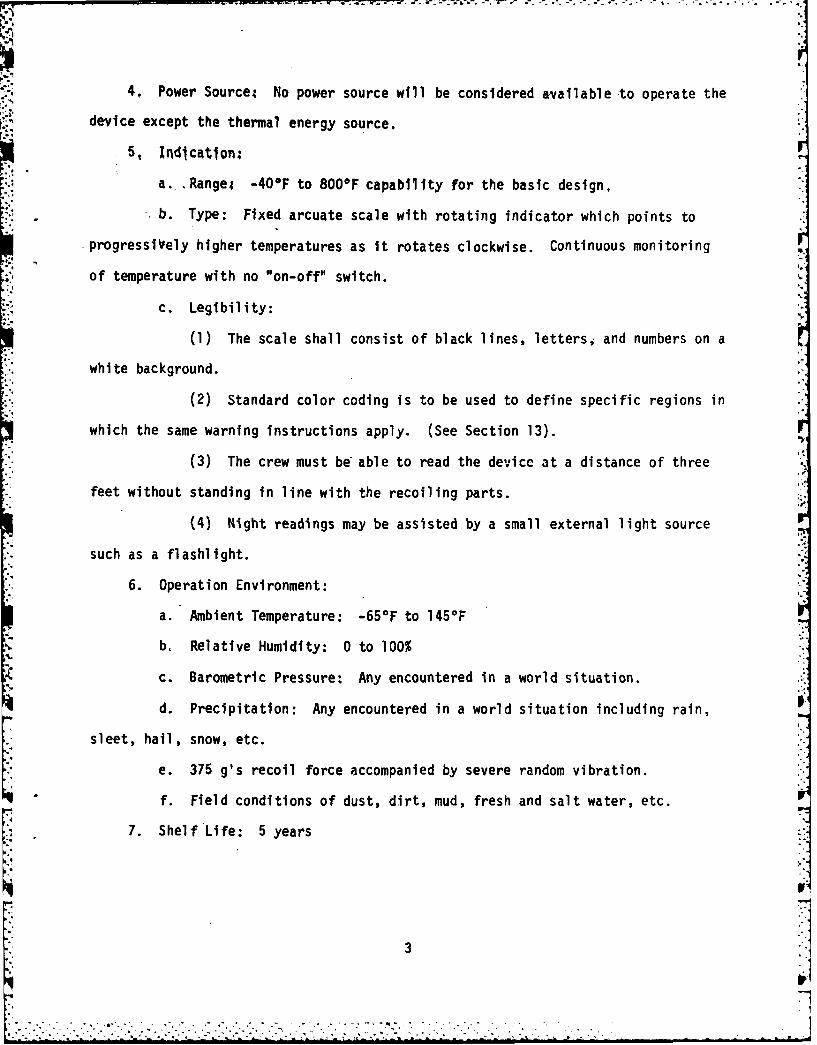
',7.4. Power Source No power source will be considered available to operate the
device except the thermal energy source.
5, Indication;
a. ,Rangei -40*F to 800F capability for the basic design,
b. Type: Fixed arcuate scale with rotating indicator which points to
progressiVely higher temperatures as it rotates clockwise. Continuous monitoring
of temperature with no "on-off" switch.
c. Legibility:
(1) The scale shall consist of black lines, lettersi and numbers on a
white background.
(2) Standard color coding is to be used to define specific regions in
which the same warning instructions apply. (See Section 13).
(3) The crew must be able to read the device at a distance of three
feet without standing in line with the recoiling parts.
(4) Night readings may be assisted by a small external light source
such as a flashlight.
6. Operation Environment:
a. Ambient Temperature: -65*F to 145°F
b. Relative Humidity: 0 to 100%
c. Barometric Pressure: Any encountered in a world situation.
d. Precipitation: Any encountered in a world situation including rain,
sleet, hail, snow, etc. -
e. 375 g's recoil force accompanied by severe random vibration.
f. Field conditions of dust, dirt, mud, fresh and salt water, etc. W
7. Shelf Life: 5 years
31
. ...V . ' .. ' .' ." : >. . ." ." " .' -. . .. " .'. " ' .' -- '". . "' ,:-. " -

8. Operational Life: 5 years or 7,500 EFC rounds. (Recalibration or repair
may be performed as necessary during this period).
9. Accuracy: +50F at the critical temperatures determined for each cannon.
10. Response Time: 99% of the external tube temperature change within
20 seconds.
11. Simplicity: The device must be simple enough to use at unit level without
specialized training.
12. Reliability: The device will perform its specified functions with 99.99%
rel iabil i ty.
13. Color Coding:
a. A three color standard color-code system will be used which will be
interpretted in the same manner for each cannon.
b. Colors/Interpretations:
(1) Green: Completely safe. No possibility of cook-off. Cold tube
misfire procedures apply.
(2) Yellow: Cook-off can occur five minutes or more after loading.
Hot tube misfire procedures apply.
(3) Red: Cook-off can occur within five minutes after loading. Do
not load or fire cannon except in combat emergency.
14. Operational Checks: Appropriate scale markings must be present so that
the crew may compare the indicated temperature of a cold tube (before firing) with
the ambient temperature.
15. Calibration:
a. Initial calibration will be performed during manufacturing at either
of the two temperatures specified in Section 13. The device will be checked for
stated accuracy over full scale per Section 9.
4
.-. r

: -- - - --., - - - - . . . -. . . -- r L _~v -- . ? -. - .-o - - -. -'.
b. Subsequent recalibration may be performed as necessary at DS or higher
echelon maintenance levels. Any convenient temperature may be used and a full
scale accuracy check is not required.
16. Repair: The device may be repaired or refurbished as necessary at a DS
or higher level of maintenance.
At this time (March 1974) the EDO Corporation, College Point, New York
submitted a technical proposal for an electronic thermal warning device. The device
was designed to utilize seven (7) battery operated ferrite temperature sensors to
indicate seven discrete temperature values. It included a readout device whi
could give either the safe time to fire or tube temperature in seven intervaI
The device had not been built or tested. The cost estimate was $985. After h
debate, this proposal was dropped for the already proven mechanical device wh
cost only $388. The additional advantage of continuous output was considered a
necessary feature.
The mechanical TWD which had been developed for the M198 Howitzer consisted
of a mercury filled stainless steel "bulb" (3/8 inch diameter) and a stainless
steel "capillary" (5/32 inch diameter) which connects the bulb to a mechanical
temperature indicator. The bulb and capillary assembly is manufactured by the
Partlow Corporation, New Hartford, New York. The column of mercury within the
bulb and capillary is capped by a piston-in-cylinder assembly providing linear
movement directly relative to the temperature change. The piston is linked to a
temperature dial indicating the tube temperature in the vicinity of the mercury
bulb. (See Figure 1). The mercury bulb and capillary are mounted to the outside
surface of the cannon tube and the temperature dial is mounted on the breech ring
where it is easily seen by the gun crew. (See Figure 2). When mounted, the center
of the mercury bulb is located approximately 36 inches forward of the rear face of
the tube. This is directly over the tube forcing cone and forward parts of the
5 WA

LJ
CD
8-
CLi
LLaA

p..
1-
L&J
CiJJ
I-.

. W
. I
zone 8 propelling charge. Since the mercury bulb is mounted to the outside surface
of the cannon but the meaningful tube temperature is that of the bore, consideration
is made for the difference between inside and outside tube surface temperatures.
Using close to worst case conditions (propelling charges at 145°F, 10 mph wind
velocity and -10°F ambient temperature), computer simulations were generated to
predict inside tube surface temperature. From this, a TWD temperature reading was
calculated below which cook-offs would probably occur only 0.5% of the time (3500F).1
The TWD temperature dial is divided into three color zones; green indicating
a "cold" tube (0* to 170°F), yellow indicating a "warm" tube (1709 to 350°F), and
red indicating a "hot" tube (above 3500F). Each color zone has specific misfire
procedures. If the outdoor temperature is expected to reach 100'F during the day,
special hot weather misfire procedures apply. 300*F is the "hot" tube cut-off TWD
reading during hot weather. This makes provision for the ammunition at a higher
temperature prior to loading the weapon.
The installation of a TWD in the M185 Howitzer cannon tube requires the
machining of a slot in the cannon tube outside surface to embed the mercury bulb
and capillary below the outside surface. This is necessary for the M185 Howitzer
because this cannon is mounted and recoils through concentric recoil bearings.
The M198 Howitzer is-mounted in a recoil mechanism which supports the cannon
breech end on rails, leaving the top of the tube exposed. This allows external
mounting of the TWD bulb and capillary. No slots are necessary for the TWD in the
M198 Howitzer.
Vottis, P.M., and Hasenbein, R.G., DRDAR-LCB-DA DF dated 23 August 1979, subject:Thermal W;arning Device (TWD) for the M198 155mm Howitzer, ARRADCOM, Benet WeaponsLaboratory, Watervliet, NY. -
8
U V. . . : ._ . . .- .. . . . . . . . , -. > . :::; . . -:

A design requirement is the machining of the slot into the M185 Howitzer tube
must not reduce the fatigue life of the tube. It was necessary to design a slot
with a cross section which did not produce a stress concentrator greater than that
- created by the recoil keyway. The fatigue life of the production tube is determined
by cracks forming at the fillets of the keyway and progressing inward toward the
bore. The first prototype slot design was of circular cross section for the mercury
bulb (.395 inch depth) and semi-circular cross section for the capillary (.290 inch
depth). The bulb and capillary were held in place with epoxy, which was filled
into the slot after the bulb and capillary were installed. This prototype was
tested at Aberdeen Proving Ground as a "piggy-back" to the Product Improvement
Validation RAM M109/M203 test in November 1979. The prototype quickly proved to be
unsuccessful since the epoxy is brittle and unable to accommodate the tube dilation
imposed by the firing pressure and temperature. The epoxy chipped and broke away
in some areas. Additionally, when the tube was returned to Benet Weapons Laboratory
for in-house fatigue testing, it failed prematurely at the TWO slot after 2427
cycles @ 56000 psi (M203 charge pressures).
These failures required the complete redesign of not only the slot but also
the method of securing the bulb and capillary within the slot. To reduce the
stress concentration created by the mercury bulb slot, it was reduced in depth by
* '.040 inch (10%) and increased in width. The cross-section of the capillary slot
was also redesigned to be similar to that of the bulb slot but proportionally
smaller. (See Figure 3). The principle behind this design change was recommended
* by the Research Branch, Benet Weapons Laboratory (BWL). Reducing the depth of the
slot required a reduction in the diameter of the mercury bulb. The next smaller
size standard bulb (5/16 inch diameter) replaced the original bulb.
9

- - ~N< wr- -~-~------------.-'0-' r ' - NV~2 %~ t ark ... '- ------ ---- - - -
ca
(~C)
LU C-)
S I La.I
lci 3cI
(-39
L I A
"I-
LUJ
La c LaJ
= LaS
czLaI
'U =J
'Sn
La Co
LaL
el
10

As an alternate means of securing the bulb and capillary, the use of a soft
metal of low melting point such as lead to replace epoxy was considered but found
to be unacceptable because of a phenomenon called "liquid metal embrittlement".
During manufacture, a cannon tube is autofrettaged to increase fatigue life. This
process creates high residual tensile stresses in the outer diameter of the tube.
If one of the metals which cause embrittlement (lead, mercury, gallium, antimony
and indium) contact the tube when they are in a liquid phase, the tube will become
brittle and may crack. Trace amounts of such metals are sufficient to cause
embri ttl ement.
Also considered were heat transfer cements such as Thermon T-85 Heat Transfer
Cement (Thermon Manufacturing Company, San Marcos, Texas) but were not acceptable
because, similarly to epoxy, become too brittle.
A mechanical means of securing the bulb and capillary was then investigated.
Spring retainers were designed for both the bulb and capillary to fit into the
slot over the bulb and capillary holding them against the gun tube. (See Figure 4).
Annealed SAE 1075 spring steel of .020 inch thickness was used for the spring
retainers and heat treated to Rc 35-40 after shaping. Axial movement of the bulb,
capillary and spring retainers was prevented in both recoil and counterrecoil by
the manner in which they were mounted within the slot and secured to the cannon.
To prevent movement between the bulb or capillary and the retainers, two
methods were tested. The first was to solder the bulb and capillary to the retainers
with high strength silver bearing solder (7% silver, 93% tin). Lead solder was not
used due to its lower strength and possible liquid metal embrittlement to the cannon
tube. The second method was the use of a filler material similar to the failed
epoxy but substantially more resilient. General Electric Room Temperature
Vulcanizing Silicone Rubber Cement (RTV 60) was selected because of its high
melting point and ability to withstand 300% elongation.
11":
• °.. . .. ° .. ... .........

LI).
cc 2c
ccJ
9K
cc.CL
(~4~ -
*.1 12

During this time frame (May 1980) the Product Improvement Program to establish
compatibility of the M203 propelling charge with the 155mm M109A2/3 Self Propelled
Howitzer was not accepted for type classification. This was due to unfavorable
results following a 4000 round test program to assess RAM-D characteristics of the
weapon and blast and over pressure impact2. The M119 zone 8 propelling charge then
became the maximum charge for this weapon. All subsequent testing regarding the
TWD was conducted with the M119 charge. When the M203 propelling charge was not
approved for use in the MlO9A1/A2/A3 Howitzer, the justification for adoption of
the TD was diminished.
The new design was tested in-house at Benet Lab as both a "C specimen" test
to determine the affect on tube fatigue life and a "Drop" test simulating cannon
recoil to test the method of physical attachment of the hardware.
The "C specimen" tests a section of the cannon tube two inches thick with a
small opening machined completely through the specimen and directly opposite the
stress concentrator being tested. (See Figure 5). The specimen is externally
loaded to produce stresses which closely approximate the service stresses at any
point in the specimen. Actual tube failures and simulation test results have
agreed closely indicating these experiments are a good measure of actual tube
behavior 3. The results of this test indicated the life with the thermal device
slot is a factor of 1.4 greater than the life with the keyway. It was concluded
2Merritt, MG, CG; ATSF-CD-MW teletype, 12 May 80, Ft. Sill, OK.
3Kapp, J.A. and. Underwood, J.H., "An Interim Report of the Simulation Tests toDetermine the Keyway Fatigue Life of the M185 Tube", ARRADCOM, Benet WeaponsLaboratory, Watervliet, NY.
13
.................. *. ...
.. . . . . . . . . . . . . . . . . ..,

I I I I* . I I g
I I I II I I II 'I *1 I
Tb4,.
-~ z
(JI~Ja.U,
L)
U,
.p.U-
*~1."
-I
14
.3.4
N~ 3 * 4 -- - . . . . .
that the stress concentration effect of the thermal device slot is less than that
of the existing recoil keyway and the addition of the thermal device slot to the
4tube would have no large effect on the life of the tube
The "DrQp" test simulates cannon recoil using a standard Var-Pulse Machine.
A section of gun tube approximately three feet in length is taken from a cannon in
the area of the TWD slot. The TWD is installed in the slot and the tube section
mounted in the Var-Pulse Machine. The inertial load of firing is simulated in the
axial direction at both 250g and 300g (maximum for the M185 Howitzer) by raising
the tube section to a pre-determined height. The section is then .dropped upon a
cushioned foundation which absorbs the inertial shock and measures it electronically.
For this test, the TWD was cycled 300 times at 250g and 200 times at 300g and was
conducted for both methods of securing the bulb and capillary to the retainers;
solder and RTV60. The specimen was examined at regular intervals for TWD slippage
or damage. No slipping or damage was detected during the test and both the solder
and RTV60 performed successfully.
A TECOM evaluation of the TWD was conducted at Aberdeen Proving Ground between
9 January and 17 February 1981. The objectives of the TECOM test were to determine:
a. The dynamic response to heat input of the 155mm M185 Howitzer TWO.
b. TWD system integrity, adequacy of installation and safety through
endurance firing.
c. Which of the two fastening methods is more effective.
d. The effects of accidental crimping on the accuracy of the TWD and any
impact on safety.
4Underwood, J.H. and Brown, B.B., DRDAR-LCB-RM DF dated 10 Jul 80, subj: FatigueLife Simulation Tests for Thermal Device Notch in M185 Tube, ARRADCOM, BenetWeapons Laboratory, Watervliet, NY.
15
~1

The test involved firing 300 M119 zone 8 propelling charges with M107 projectiles.
Both methods of securing the bulb and capillary to the retainers were tested for
endurance. After all test firing was completed, a crimp safety check of the TWD
was made in the physical test laboratory.
Prior to each method of installation to compare TWD readings with actual
readings, six iron constantan thermocouples were installed in three equally spaced
locations on either side of the mercury bulb temperature sensor to measure the
axial temperature profile. During the course of installation and testing, some
thermocouples were lost. These losses were anticipated and was the reasoning for
placing the thermocouples on both sides of the temperature sensor. A manual
temperature probe was also used to measure the chamber temperature at the origin
of rifling.
Four firing phases were conducted. For each method of installation, 100
rounds were fired in one day, the cannon allowed to cool overnight, then fired 50
rounds the following day.
No problems with TWD system integrity or interference were noted in either
method of installation. There were no safety problems and the TWD performed
successfully. Correlation between the TWD and thermocouples was good. However,
installing the TWD with the RTV 60 silicone rubber was awkward, messy and lengthy.
The solder method proved superior due to quicker and easier TWD installation.
Neither method caused any problems in mating the tube to the breech ring. TECOM
therefore recommended the solder installation technique be adopted for the
MlO9Al/A2/A3 Howitzer TWD.
16
- ________

One TWO was deliberately crimped at the capillary to observe adverse affects,
if any. The TWO was placed in an oil bath and calibration checks run before and
after crimping. No differences in temperature readings resulted5 .IP
Shortly after the successful completion of the TECOM test, the TWD program
was subjected to the newly instituted "Independent Design Review" (IDR). The IDR
is an ARRADCOM Large Caliber Weapon Systems Laboratory (LCWSL) Standing Operating
Procedure (SOP No. 15-2 dated 26 Jan 81). The intention is to review the technical
areas of all Large Caliber programs for design and interface considerations prior
to submission of the program to the CCB for a fielding decision.
The IDR process involves the creation of a team of technology area experts
selected from the Large Caliber community and headed by a chairperson proposed by
the Applied Science Division, LCWSL. At the initial IDR meeting, the developer
briefs the review team and makes available any information requested. Included
are a physical and operational description, drawings and specifications, analysis,
test data and results. Also reviewed were designs regarding heat transfer, impact
on cannon, impact on system, producibility, ILS, reliability, maintainability,
training, manuals, misfire procedures and safety.
From the above topics, the IDR team created 38 questions from 23 concerns
which required forma.l detailed written responses. The responses provided to the
IDR team were satisfactory and the final meeting and presentation to the Director
of Large Caliber Weapon Systems Laboratory was successfully completed. The total
cost of the IDR to the project was $7866 expended by the IDR team plus three months
engineering time and funding.
5Taylor, H.J., "Final Report -Product Improvement Proposal (PIP) for l5Snun M185Howitzer Thermal Warning Device (PIP 1-79-05-2006)", TECOM Project No. 2-WE-205-185-098, Test Agency Report No. APG-MT-5509, US Army Aberdeen Proving Ground,Aberdeen, MD, March, 1981. r
17

One important issue resulted from the IDR. This involved the effect on the
breech ring from mounting the ThD temperature dial. A flat surface and four
threaded holes are machined into the breech ring which could reduce the fatigue
life. The developer agreed to investigate this issue.
Research of the iND files revealed no studies on the fatigue effect of the
four holes. Additionally, the PIP itself included no funds to perform a breech
ring fatigue test. Correspondence with the Research Branch, BWL resulted in concern
over the particular location of the bolt holes directly opposite the I.D. thread
relief groove. This is the highest stressed region in this type of breech ring.
A finite element analysis was not considered appropriate due to the physical
complexity of the breech ring. Since there was no other suitable location on the
breech ring to mount the temperature dial and the only alternative was to redesign
the dial housing, further fatigue testing would be required before the TWD could
be type classified on the MlO9AI/A2/A3 Howitzer.
To receive a "Safe Fatigue Life" for the modified breech ring, a six specimen
test is required per TECOM agreement. The testing is conducthd in-house by the
Applied Mathematics and Mechanics Section, BWL. It involves pressure cycling a
stub tube-breech ring-breech block combination in a manner simulating actual firing.
The cost to perform this test was estimated at $281,000 plus additional funds for
engineering support. The high cost is due to the hardware involved, i.e., three
stub tubes are required for each breech ring at a cost of over $6,000 each plus the
cost of breech rings and blocks. Also, the cost of the test operation itself is
$17,000 per breech ring. A funding request was submitted to ARRCOM whose response
* was:
a. There are no PIP funds available for FY81 or FY82; earliest is FY83.
b. The user sees a need for the TWD in the M109Al/A2/A3 Howitzer but it is a
low priority item and is not willing to pull funds from other programs.
* T18
Shortly thereafter, ARRCOM requested the developer to make a formal presentation,
including funding requirements, to a Level II Configuration Control Board (CCB).
Having accomplished this, the official CCB reply was a request for a written
response, in more detail, regarding the same issues.
The CCB reply to the written response was a request for a second formal
presentation to both a Level II and Level I CCB. This presentation would include
all aspects of the program and focus on the breech ring problem and related costs.
A presentation was prepared which stressed the importance of a TWD and the
dangers or hazardous situations which currently may occur on the M109AI Howitzer
but are prevented by the TWD on the M198 Howitzer if misfire procedures are
properly followed. This argument, however, depended upon a high rate of fire
(one round per minute) of adequate duration to raise the tube temperature to
greater than 170 0F. In normal training exercises this tube temperature is not
achieved and during combat the TWD would have to be ignored regardless of the
temperature reading. In view of this, plus the M203 propelling charge MIO9Al/A2/A3
incompatibility and the unavailability of immediate funds, the Level II CCB
recommended to the Level I CCB that the TWD program be terminated. The user was
contacted at the Ft. Sill Field Artillery School who agreed with the recommendation.
The user also stated the TWD is no longer considered essential for the MlO9AI/A2/A3
Howitzer. A written confirmation was issued stating 1 ... the potential increase to
current capability and margin of safety is viewed as being less than the potential
increases offered by other on-going actions to improve overall weapon RAM,
survivability and combat capabilities. This is mandated by priority funding
considerations of competing systems".6 The PIP was then terminated by ARRCOM
6Baggott, C.P., ATSF-CD-MW Letter dated 19 Feb 82, subj: 155mm MlO9Al/A2/A3 SPHowitzer Thermal Warning Device, PIP 1-79-05-2006, USAFAS, Ft. Sill, OK.
19
-~~~~~~~~~~~~~~~~~~.---.. .-.... .. . .. .• " --.. . . . -. "i:' :" -' "---" ' .,,..,,

Level I Confiquration Control Board Directive of 28 Jan 82.
SUMMARY
The 155mm MlO9Al/A2/A3 Howitzer Thermal Warning Device Product Improvement
Program was undertaken to provide accurate cannon tube temperature data to the gun
crew. At the time the proposal was written, there appeared to be a genuine need
for a Thermal Warning Device on this weapon. However, during the engineering phase,
several events occurred reducing the justification for adoption. Additionally,
unanticipated breech ring fatigue testing required funding which had not been provided
for in the program. After all design problems had been resolved and the device was
successfully tested by TECOM, the program was terminated by ARRCOM in January 1982.
20

REFERENCES
1. Vottis, P.M., and Hasenbein, R.G., DRDAR-LCB-DA DF dated 23 August 1979, subject:Thermal Warning Device (TWD) for the M198 Howitzer, ARRADCOM, Benet Weapons Laboratory,Watervliet, NY.
2. Merritt, MG, CG; ATSF-CD-1W teletype, 12 May 80, Ft. Sill, OK.
3. Kapp., J.A. and Underwood, 3.H., "An Interim Report of the Simulation Tests toDetermine the Keyway Fati.gue Life of the M185 Tube", ARRADCOM, Benet WeaponsLaboratory, Watervliet, NY.
4. Underwood, J.H. and Brown, B.B., DRDAR-LCB-RM DF dated 10 Jul 80, subj: FatigueLife Simulation Tests for Thermal Device Notch in M185 Tube, ARRADCOM, Benet WeaponsLaboratory, Watervliet, NY.
5. Taylor, H.J., "Final Report - Product Improvement Proposal (PIP) for 155mm M185
Howitzer Thermal Warning Device (PIP 1-79-05-2006)", TECOM Project No. 2-WE-205-185-098, Test Agency Report No. APG-MT-5509, US Army Aberdeen Proving Ground, Aberdeen,MD, March 1981.
6. Baggott, C.P., ATSF-CD-MW Letter dated 19 Feb 82, subj: 155mm MlO9A/A2/A3 SPHowitzer Thermal Warning Device, PIP 1-79-05-2006, USAFAS, Ft. Sill, OK.
IF
21
.1

TECHNICAL REPORT INTERNAL DISTRIBUTION LIST
NO. OFCOPIES
CHIEF, DEVELOPMENT ENGINEERING BRANCHATTNI: DRAR-LCB-DP1
-DR1-riS (SYSTEMS)-DS (ICAS GROUP)1-DC1
CHIEF, ENGINEERING SUPPORT BRANCH 1ATTN: DRDAR-LCB-SE 1
CHIEF, RESEARCH BRANCH 2ATTN: DRDAR-LCB-R (ELLEN FOGARTY) I
-RA I-RP 1
-Rp I
TECHNICAL LIBRARY 5ATTN: DRDAR-LCB-TL
TECHNICAL PUBLICATIONS & EDITING UNIT 2ATTN: DRDA-LCB- L
DIRECTOR, OPERATIONS DIRECTORATE1
DIRECTOR, PROCUREMENT DIRECTORATE1
DIRECTOR, PRODUCT ASSURANCE DIRECTORATE1
-IT 1
NOTE:T PEANTIOFS DIRECTORATET WEPN AOAOY TN RA-C-
OF ANY REQUIRED CHANGES.

TECHNICAL REPORT EXTERNAL DISTRIBUTION LIST
NO. OF NO. OFCOPIES COPIES
ASST SEC OF THE ARMY COMMANDERRESEARCH 4 DEVELOPMENT ROCK ISLAND ARSENALATTN: DEP FOR SCI & TECH 1 ATTN: SARRI-ENM (MAT SCI DIV)THE PENTAGON ROCK ISLAND, IL 61299WASHINGTON, D.C. 20315
DIRECTORCOMMANDER US ARMY INDUSTRIAL BASE ENG ACTDEFENSE TECHNICAL INFO CENTER ATTN: DRXIB-MATTN: DTIC-DDA 12 ROCK ISLAND, IL 61299CAMERON STATION
ALEXANDRIA, VA 22314 COMMANDERUS ARMY TANK-AUTMV R&D COND
COMMANDER ATTN: TECH LIB - DRSTA-TSLUS ARMY MAT DEV & READ COMD WARREN, MICHIGAN 48090ATTN: DRCDE-SG 15001 EISENHOWER AVE COMMANDERALEXANDRIA, VA 22333 US ARMY TANK-AUTMV COMD
ATTN: DRSTA-RCCOMMANDER WARREN, MICHIGAN 48090US ARMY ARRADCOMATTN: DRDAR-LC 1 CO*ADER
DRDAR-LCA (PLASTICS TECH 1 US MILITARY ACADEMYEVAL CEN) ATTN: CHMN, MECH ENGR DEPT
* DRDAR-LCE 1 WEST POINT, NY 10996DRDAR-LCM (BLDG 321) 1DRDAR-LCS 1 US ARMY MISSILE COMDDRDAR-LCU 1 REDSTONE SCIENTIFIC INFO CENDRDAR-LCW 1 ATTN: DOCUMENTS SECT, BLDG 4484 2DRDAR-TSS (STINFO) 2 REDSTONE ARSENAL, AL 35898
DOVER, NJ 07801
COMMANDERDIRECTOR US ARMY FGN SCIENCE & TECH CENUS ARMY BALLISTIC RESEARCH LABORATORY ATTN: DRXST-SDATTN: DRDAR-TSB-S (STINFO) 1 220 7TH STREET, N.E.ABERDEEN PROVING GROUND, MD 21005 CHARLOTTESVILLE, VA 22901
COMMANDER COMMANDERUS ARMY ARRCOM US ARMY MATERIALS & MECHANICSATTN: DRSAR-LEP-L 1 RESEARCH CENTERROCK ISLAND ARSENAL ATTN: TECH LIB - DRXMR-PL 2ROCK ISLAND, IL 61299 WATERTOWN, MASS 02172
NOTE: PLEASE NOTIFY COMMANDER, ARRADCOM, ATTN: BENET WEAPONS LABORATORY,DRDAR-LCB-TL, WATERVLIET ARSENAL, WATERVLIET, N.Y. 12189, OF ANYREQUIRED CHANGES.
' .,. .-.- ., . .- . . , . . ;. . .. . ./ .. . . -.. , ,". . . -....... -. , i ," .
TECHNICAL REPORT EXTERNAL DISTRIBUTION LIST (CONT.)
NO. OF NO. OFCOPIES COPIES
COMMANDER DIRECTORUS ARMY RESEARCH OFFICE US NAVAL RESEARCH LABATTN: CHIEF, IPO 1 ATTN: DIR, MECH DIV 1P.O. BOX 12211 CODE 26-27 (DOC LIB) 1RESEARCH TRIANGLE PARK, NC. 27709 WASHINGTON, D.C. 20375
COMMANDER METALS 6 CERAMICS INFO CENUS ARMY HARRY DIAMOND LAB BATTELLE COLUMBUS LAB 1ATTN: TECH LIB 1 505 KING AVE2800 POWDER MILL ROAD COLUMBUS, OHIO 43201ADELPHIA, MD 20783
MATERIEL SYSTEMS ANALYSIS ACTVCOMMANDER ATTN: DRSXY-MP 1NAVAL SURFACE WEAPONS CEN ABERDEEN PROVING GROUNDATTN: TECHNICAL LIBRARY 1 MARYLAND 21005
CODE X212DAHLGREN, VA 22448 COMMANDER
US ARMY ABERDEEN PROVING GROUNDCOMMANDER ATTN: STEAP-MT-A 1US ARMY ARRCOM ABERDEEN PROVING GROUND, MD 21005ATTN: DRSAR-LEM 5ROCK ISLAND, IL 61299 PROJECT MANAGER
CANNON ARTILLERY WPNS SYSTEMSCOMMANDER DARCOMUS ARMY TEST & EVAL COMD ATTN: DRCPM-CAWS-WP 2ATTN: DRSTE-CM-F 1 DOVER, NJ 07801ABERDEEN PROVING GROUND, MD 21005
p
NOTE: PLEASE NOTIFY COMMANDER, ARRADCOM, ATTN: BENET WEAPONS LABORATORY,DRDAR-LCB-TL, WATERVLIET ARSENAL, WATERVLIET, N.Y. 12189, OF ANYREQUIRED CHANGES.
t- . . ; . - . -. .. .. . . .. . -. . . .- . . - ; o . .o . . . : . : . . . . . . . . - , : , .. ... . - ,


![DTIC QUALIT ^JtjJJLiUJi, China · 2020. 2. 20. · JPRS-CAR-91-023 25 APRIL 1991 JPRS Report— DTIC QUALIT --v „ ^JtjJJLiUJi, China QIUSHI [SEEKING TRUTH] No 4, 16 February 1991](https://img.pdfslide.us/doc/110x75/60e0f73fa6c0b8164212769b/dtic-qualit-jtjjjliuji-china-2020-2-20-jprs-car-91-023-25-april-1991-jprs.jpg)