Embed Size (px)
Citation preview

pztr'4
547 W. Jackson Boulevard, Chicago, IL 60661 si;i-s:n.r>goo metrarail. com
November 8, 2019
Subject: Invitation for Bid No. 42385A
Construction Services to Upgrade the Existing Union Pacific Railroad SandingSystem Located at 400 N. Pulaski Road, Chicago, ILAddendum No. l
Dear Sir/Madam:
The subject Addendum is being issued to correct, amend, add and/or delete certain words, phrases, sentences, orparagraphs in Invitation for Bid No. 42385A.
This Addendum No. 1 consists of'.
1. Questions Metra has received and the responses from our agency (see attached).
2. p.? Exhibit R, Section 1100 0l- Silica Sand Storage and Handling System and r3333. with theattached Revised Exhibit R, Section 11 00 0l- Silica Sand Storage and Handling System.
3. Attached is the Pre-Bid Meeting Attendance Sheet.
The question period is closed. Metra will be unable to respond to any additional questions submitted bycontractors.
The Bid Opening Date remains November 21, 2019 at the time and place previously advertised.
All addenda are to be acknowledged in Proposal/Contract, Section 4. 11 Addenda. Failure to acknowledgeaddenda may be cause for bid to be considered non-responsive.
Sincerely,
.,j,? 4?James Barker
Department HeadConstruction & Facilities Maintenance Procurement
SB
Attachments

Addendum No. 1 IFB No. 42385A
QUESTIONS/RESPONSES
Listed below are additional questions (“Q”) Metra has received and the responses (“R”) from our agency: Q1: Below are RFIs 1 through 19. Questions concerning section 11 00 01, we note the following:
1. 1.2.A.1: The silo can (and should) be welded for the specified capacity on the drawings
(4500 cu ft) 2. 1.2.A.9: There is no unloading spout in the scope shown on the drawings 3. 1.2.A.10: There is no belt scale in the scope shown on the drawings 4. 1.5.B: The silo is filled by pneumatic truck per the drawings, not mechanically; there is no
rail unload on the drawings, nor belt with scale nor bucket elevator, nor rotary distributor, etc. There is no retractable spout or truck scale, or compact filter module shown on the drawings. The silo is not discharging into a truck on the drawings.
5. 1.5.D: The silo on the drawings is 4500 cu ft cap; does not at all need to be close to 25 ft diameter or 82 ft tall! There is no need to have the ability to drive a truck under the silo.
6. 2.1.1: The silo can and should be welded, not bolted, for the cost and the size involved. A ladder, not a spiral stair, is shown for access on the drawings.
7. 2.1.2: not shown on the drawings 8. 2.1.3: not shown on the drawings 9. 2.1.4: not shown on the drawings 10. 2.1.5: not shown on the drawings 11. 2.1.6: not mechanical fill but rather pneumatic fill of the silo shown on the drawings 12. 2.1.8: not rail unload but truck unload shown on the drawings 13. 2.1.11: not shown on the drawings 14. 2.1.12: not shown on the drawings 15. 2.1.13: not shown on the drawings 16. 2.1.15: not shown on the drawings 17. 2.1.16: not shown on the drawings 18. 2.1.17 not shown on the drawings 19. 3.2: Silo should be welded, not bolted, as noted above.
R1: Below are the Q1 responses for the above RFIs 1 through 1 concerning Specification Section 11
00 01. Specification Section 11 00 01 has been revised and attached. 1. Silo can be welded or bolted provided 1.3. (Submittals) is adhered to. 2. The unloading spout shall be eliminated. 3. Correct, there will be no belt scale. 4. Correct, the silo will be filled by pneumatic truck. The silo will discharge to a pneumatic conveying system. 5. To obtain 4,500 cubic feet capacity, there is a 12-foot diameter and 54-foot height for the new silo. 6. See response to #1, above. Spiral stairs will not be part of this project. 7. Hopper to be provided by Contractor at bottom of silo. 8. Belt conveyor not required. 9. Belt scale not required.
1

Addendum No. 1 IFB No. 42385A
10. Manual and automatic gates not required. 11. Pneumatic fill is correct. 12. Truck unloading is correct. 13. Bucket elevator is not required. 14. Rotary distributor is not required. 15. Chutes is not required. 16. Retractable loading spout is not required. 17. Loading spout dust collector is not required. 18. Weigh scale is not required. 19. See response to #1, above.
Q2: Please confirm that Metra will supply all the required sand for testing and start up?
R2: Correct.
Q3: Will the contractor be allowed to mobilize a crane along track 4, in front of the Diesel Shop Building? See attached Reference Document No. 1.
R3: The Contractor’s crane can occupy the area to the east of the building for a period of time no longer than 2-days.
Q4: Will Metra claim any of the equipment designated for removal?
R4: All equipment to be removed is to become the property of the Contractor.
Q5: Will the contractor be allowed to use the overhead crane in the Diesel Shop building and the Engine Overhaul Room?
R5: No.
Q6: The north elevation of building M19A, Stores, and the Diesel Shop Building has no legend designating a working time? Can the contractor assume that any exterior work along the north elevation can be completed during normal working hours?
R6:
Exterior to the building, with the exception of the roof, the working hours are from 4 p.m. to 7 a.m. of the next morning during weekdays, and all day during weekends.
Q7: Can the contractor work on the roof of the Diesel Shop Building during normal working hours?
R7: If materials and equipment are already placed on the roof, the Contractor may work on the roof of the Diesel Shop Building during daytime hours (6 a.m. to 6 p.m.). Otherwise, as previously stated, exterior to the building, all work must be done from 4 p.m. to 7 a.m. of the next morning during weekdays, and all day during weekends.
Q8: Please confirm that all excavated spoils will remain on site in an area designated by Metra?
R8: Correct.
2


DIVISION 11: EQUIPMENT
SECTION 11 00 01
SILICA SAND STORAGE AND HANDLING SYSTEM
PART 1 - GENERAL
1.1 RELATED DOCUMENTS
A. Drawings and general provisions of the Contract, including General and Supplementary Conditions and Division 01 Specification Sections, apply to this Section.
1.2 SUMMARY
A. This Section includes the following types of equipment used in silica sand storage and handling systems: 1. Storage silo, flat panel bolted or welded, complete with accessories.2. Manual and automatic gates.3.2. Bin vent filter. 4.3. Level controls. 5.4. Controls. 6.5. Compressed air. 7.6. Electrical. 8.7. Compressed air piping. 9.8. Retractable unloading spout and Ddust collection. 10. Belt scale.11.9. Lighting. 12.10. Convenience Power. 13.11. Foundation. 14.12. Control room.
1.3 SUBMITTALS
A. Product Data: For each type of product and equipment indicated.
B. Shop Drawings: Detail silica sand storage and handling system, silo and structural system, equipment assemblies, control, electrical and mechanical systems, foundation, and indicate dimensions, weights, loads, clearances, field installation procedures, components, and location and sizes. 1. P&ID diagrams: from railcar unload through truck fill.2. Wiring diagrams: Power, signal and control wiring.3. Installation drawings and data: Components, accessories, and equipment.4. Color sample for silo.
C. Certificates of shop inspections and quality control data reports:
Addendum No. 1 IFB No. 42385A
EXHIBIT R

D. Welding certifications:
E. Source quality test reports:
F. Field quality-control test reports.
G. Operation and maintenance data: for system and components. 1. Submit (5) hard copy manuals, ring bound in heavy-duty binders, project data on
cover and binding edge, Letter size format for typical pages, 11x17 format fordrawings with “engineer” fold.
2. Submit (2) digital media (CD or DVD) manuals, with hard copy data in “.pdf” format.
1.4 QUALITY ASSURANCE
A. Source Limitations: Obtain each system component through one source from a single manufacturer.
B. Product Options: System requirements are based upon the specific system and operational characteristics indicated.
C. Welding: Quality process and operators according to AWS D1.1.
D. Electrical Components, Devices, Accessories: Listed and labeled as defined in NFPA 70, Article 100, and marked for intended use.
1.5 PROJECT CONDITIONS
A. Interruption of Existing Services: Do not interrupt existing power, water or other utility services without (5) days prior notice of proposed interruption to Owner, and approval by Construction Manager.
B. Material Handling Properties: 1. Silo fill rate: 300 TPH2. Silo fill method: MechanicalPneumatic
a. Railcar hopperTruck unload.b. Inclined belt conveyor with belt scalec. Bucket elevator.d. Rotary distributore.b. Chutes.
3. Silo discharge rate: 300 TPH4. Silo discharge method: MechanicalPneumatic
a. Manual slide gateb. Pneumatic slide gate.c. Compact filter module (dust collection).d. Retractable spout.e. Truck scale.
5. Silo discharge receiver:a. Enclosed silica sand truck, 2 to 3 ports.
Addendum No. 1 IFB No. 42385A
EXHIBIT R

C. Silica Sand Analysis: METRA to provide sample of silica sand for analysis or provide material characteristics of the specific silica sand varieties.
D. Design Criteria: 1. Location City: Chicago2. Location State: Illinois3. Location Zip Code: 606244. Product: Silica Sand5. Product Density, volume:6.5. Product Density design: 100 lb./cf 7.6. Product Angle of Repose: 25 degrees 8.7. Required Working Capacity: 1,125320 tons each, 9,000 tons aggregate. 9.8. Silo diameter: 25 12 ft. nominal. 10.9. Silo eave height: 82 54 ft. nominal 11.10. Silo configuration: Skirt support 12.11. Hopper Slope: 45 degrees 13.12. Hopper Outlet Size: 12” to 14” diameter. 14. Drive thru clearance height: 23 ft.15. Drive thru clearance width: 12 ft.16.13. Side discharge clearance height: 17.14. Silo design load pattern: Funnel flow 18.15. Operating pressures: 2 oz./square inches positive; 0.5 oz./square inch
negative. 19.16. Roof live load: 30 psf 20.17. Platform live load: 100 psf 21.18. Seismic Zone: per IBC 2006 and ASCE 7-12 19. Wind Design: per City of Chicago Building Code Chapter 13-52.22.20. Welding according to AWS D1.1, latest edition
1.6 EXTRA MATERIALS
A. Furnish extra consumable materials at quantities indicated in equipment specification sections, with storage labels describing contents.
B. Provide spare parts list, with current pricing, or all equipment consumables.
C. Refer to the warranty statements of Section 01 77 00.
PART 2 - PRODUCTS
2.1 MANUFACTURERS
Construction Manager shall determine acceptable equipment manufacturers that meet or exceed system specifications and requirements. 1. Silo: Tank connection LLC
a. Rolled-Tapered Panel (RTP) bolted or welded storage silo.b. Lap joint or butt joint (if welded) connections for both vertical and horizontal
seams. API 12B “flanged panel” shall not be acceptable.
Addendum No. 1 IFB No. 42385A
EXHIBIT R

c. 1:12 roof sloped. Exterior spiral stair and crossovers, serrated grating treads and platform
grating.aluminum or steel caged ladder with step off platform and safety rails,OSHA compliant
d.e. Top aluminum or steel safety rail with kick plates at top of silo. e.f. Minimum shell and hopper thickness of 3/16” f.g. Manufacturer’s and applicable reference codes and standards for shell,
hopper and roof design, allowance stresses, steel and fastener properties, and other material and design characteristics.
g.h. Coasting system: Provide coating, as follows, or an alternate with the following described salient characteristics: 1) Interior: fusion 500 FBE primer, 5 mils DFT.2) Exterior: EXT Fusion 500 FBE primer, 3 mils DFT; EXT Fusion 500
SDP, 3 mils DFT.3) Exterior Color: To be selected by Construction Manager from Seller’s
standard color chart.4) Interior Color: Manufacturer’s standard “White”5) Accessories: As required for interior or exterior exposure, or hot dipped
galvanized.6) Inspection: At regular intervals to ensure quality, after final coat and
cure, inspect cure, adhesion, thickness, and holidays.
2. Transition Hopper (To be provided at bottom of Silo):a. Minimum slope angle: 45 degrees.b. Materials: AR steel on wear surfaces.c. Support: Ground supported by support frame.d. Coating System: Hot dipped galvanized.
3. Belt Conveyor:a. Inclined belt conveyor, complete with discharge hood, tail pully guard,
channel frame construction, 2-ply belting, speed sensors, mating inlet flange, mating discharge transition, motor and reducer, drive guard, sealed idlers.
b. Incline: 18 degrees max.c. Cover: enclosed.d. Supports: Frames to grade.e. Motor: 30 hp, 480 V, 3 ph, 60 hz, with Dodge reducer.f. Coating System: Manufacturer’s standard, topcoat color to match silo
exterior. 4. Belt Scale:
a. Single idler, accuracy to +/- 0.5%, single point strain gauge load cell with SShousing, heavy duty construction.
b. Coating System: Manufacturer’s standard, topcoat color to Belt Conveyor.5. Manual and automatic gates: DCL, Inc.
a. Manual slide gate with hand wheel operator, and bearing cam hardenedrollers, AR (abrasion resistant) steel lined at wear points.
b. Slide gate with pneumatic operator, AR steel lined at wear points, 2 positionswith solenoid positioning package and limit switches, required compressed air.
c. Coating System: Manufacturer’s standard, topcoat color to match siloInterior.
6.3. Bin vent filter:
Addendum No. 1 IFB No. 42385A
EXHIBIT R

a. Cartridge style bin vent filter, with maximum air to cloth ratio of 4:1.b. Reverse pulse jet, self-cleaning.c. Intervals between adjacent silos.d. Sized for product displacement during mechanical fill process, with 2 times
safety factor minimum.e. NEMA 4 timer control board, 120 V operation.f. Motor: ½ hp, 480 V, 3 ph, 60 hz, fan top mount.g. Coating System: Manufacturer’s standard topcoat color to match Silo
Exterior.7.4. Silo Level controls: Ultrasonic, Radar, or Manufacturer’s choice. 8.5. Controls and Power:
a. PLC based control system,PLC based control system fully integrated withequipment for railcar truck unload (silo fill) and silo discharge (truck fill).1) Main control panel with dependent remote panels for silo. Main control
panel shall be touch screen with push-button redundancy for primaryfunctions. Remote panels shall be push-button.
2) NEMA 4 rated enclosures.3) Integrated with level controls and truck weigh scale.4) Main control panel located inside control room.
9. Compressed air:a. Rotary screw air compressor with desiccant dryer, cold weather package.b. Sized for demand from pneumatic and duct collection.c. Galvanized piping with threaded connections. Motor: 15 hp, 480 V, 3 ph, 60
hz. d. Coating System: Manufacturer’s standard.
10.6. Control Room: a. Prefabricated control room, complete and weathertight with man door,
window, desk, insulation, siding, roofing, lighting, interior finished walls andfloor.
b. Size 10’ x 12’ x 8’c. Thru-wall packaged HVAC system.d. Motor: HVAC ½ hp, 208v.e. Coating System: Manufacturer’s standard, exterior color to be determined
from manufacturer’s standard color chart.11. Bucket elevator:
a. Rectangular cross section, carbon steel construction, 10g min. cap. And 3/16in. min. head sections, ¼ in. min. boot section, 10g min. casing, AR lined discharge and inlet, heavy duty belting and cups, clean out and inspection doors/panels.
b. Motor: 60 hp., 480v., 3 ph, 60hz, with Dodge reducer, zero speed switch,belt guard.
c. Platform, ladder, supports to silo. Jib boom for head section.d.f. Coating System: Manufacturer’s standard, top coat color to match Silo
exterior color. 12. Rotary Distributor.
a. Gear motor with brake, AR steel lined inlets and outlets, position quantity asindicated on drawings, revolving spout with seals, limit switches on position, mating inlet and discharge flanges, AR lined inlet, spout internal and outlet.
b. Motor: 1 hp, 480v, 3 ph, 60hz.
Addendum No. 1 IFB No. 42385A
EXHIBIT R

c. Coating system: Manufacturer’s standard, topcoat color to match siloexterior color.
13. Chutes:a. Tank Connection “Riffle Chute” design, allowing minimal abrasion of product
on chute surfaces. b. Flanged sections, coordinated to mate to inlet and discharge points.c. Designed for self-supporting spans.d. Coating System: Manufacturer’s standard, topcoat color to match Silo
Exterior color. 14.7. Mechanical piping and valves:
a. Galvanized piping with threaded connections for compressed and blower air.b. Copper piping with soldered connections, with heat tracing and insulation,
for water linec. Metering and shut-off valves suitable for the service, and located to allow
isolation and bypass during serviced. Strainers, traps, fittings as required by design.d.e. 4-Inch Cam-Lok Quick Coupling
15. Retractable loading spout: DCL Inc.a. Hypalon nylon with aluminum support rings, AR lined inner cone, worm drive
HD motor, air withdrawal to and supported by loading spout dust collector. b. Travel: 6 ft., or as required.c. Motor: 1 ph., 480v, 3 ph., 60hz.d. Level sense: Tilt switch interfaced with control system.e. Coating system: Manufacturer’s standard, topcoat color to match silo
Interior. 16. Loading spout dust collection: DCL, Inc.
a. Compact filter module, complete with filter cartridges, pressure gauge, ARlined inlet, TEFC withdrawal fan, pulse jet cleaning system, and required compressed air.
b. Motor: 10 hp, 480v, 3ph, 60hz, VFD rated, Premium Efficiency.c. Support: From Silo Hopper outlet and gates.d. Coating system: Manufacturer’s standard, topcoat color to match silo
Interior. 17. Weigh scale
a. Surface mounted weigh scale, complete with side rails, foundation kit, 135-ton capacity, 45-ton CLC, minimum 120 ft length.
b. Deck: Metal.c. Load cells: SS heavy duty compression.d. Indicator: Digital readout and printer, interfaced with control system.
18.8. Lighting: a. General Exterior lighting of work areas, providing minimum 2 foot-candles at
ground level.b. Interior lighting on equipment and controls areas inside skirt of silo, providing
15 foot-candles at 3’ above working surfaces.c. Lighting shall be Metal Halide of required wattage.d. Interior and exterior lighting shall be controlled with disconnects ar common
location, and adjustable timer in the control system.19.9. Convenience Power:
a. 120V, 20A service, GFCI receptacles with weather guards, at Silo skirtinteriors, Silo roof, and equipment transition points.
Addendum No. 1 IFB No. 42385A
EXHIBIT R
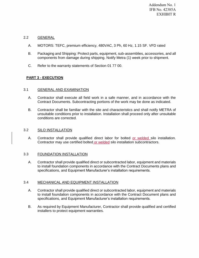
2.2 GENERAL
A. MOTORS: TEFC, premium efficiency, 480VAC, 3 Ph, 60 Hz, 1.15 SF. VFD rated
B. Packaging and Shipping: Protect parts, equipment, sub-assemblies, accessories, and all components from damage during shipping. Notify Metra (1) week prior to shipment.
C. Refer to the warranty statements of Section 01 77 00.
PART 3 - EXECUTION
3.1 GENERAL AND EXAMINATION
A. Contractor shall execute all field work in a safe manner, and in accordance with the Contract Documents. Subcontracting portions of the work may be done as indicated.
B. Contractor shall be familiar with the site and characteristics and shall notify METRA of unsuitable conditions prior to installation. Installation shall proceed only after unsuitable conditions are corrected.
3.2 SILO INSTALLATION
A. Contractor shall provide qualified direct labor for bolted or welded silo installation. Contractor may use certified bolted or welded silo installation subcontractors.
3.3 FOUNDATION INSTALLATION
A. Contractor shall provide qualified direct or subcontracted labor, equipment and materials to install foundation components in accordance with the Contract Documents plans and specifications, and Equipment Manufacturer’s installation requirements.
3.4 MECHANICAL AND EQUIPMENT INSTALLATION
A. Contractor shall provide qualified direct or subcontracted labor, equipment and materials to install foundation components in accordance with the Contract Document plans and specifications, and Equipment Manufacturer’s installation requirements.
B. As required by Equipment Manufacturer, Contractor shall provide qualified and certified installers to protect equipment warranties.
Addendum No. 1 IFB No. 42385A
EXHIBIT R

3.5 ELECTRICAL AND CONTROLS INSTALLATION
A. Contractor shall provide qualified, licensed, direct or subcontracted labor, equipment and materials to install foundation components in accordance with the Contract Document plans and specifications, and Equipment Manufacturer’s installation requirements.
3.6 SAFETY
A. Contractor shall maintain an OSHA approved safety program. Contractor shall designate a single “safety” point of contract for the project. Subcontractors shall operate under Contractor’s safety program.
B. Contractor shall maintain at project site, Material Safety Data Sheets (MSDS) for all products in use or storage.
C. OSHA Safety Ratings: Contractor and Contractor’s Subcontractors shall maintain the following OSHA safety rating: 1. EMR: Less than 1.02. RIR: Less than 5.0
3.7 FIELD QUALITY CONTROL
A. Contractor shall engage qualified installers, and equipment manufacturer’s factory-authorized service representative to inspect, test and adjust field assembled components and equipment installation, as required. This authorized representative shall be available during sanding system start-up.
B. Contractor shall maintain written and photo documentation of field work activities, including manpower, weather, actions, issues, etc.
C. Perform the following field test and inspections: 1. Leak Tests: After installation, charge systems and test for leaks. Repair leaks and
retest until no leaks exist. 2. Silo Leak Test: Exterior spray water test per manufacturer’s procedure.3. Operational Test: After electrical circuitry has been energized, start units according
to manufacturer’s requirements. Verify correct operation, adjust and retest toconfirm proper equipment operation. Safeties Test: After installation, test systemand equipment for proper safety shutdown based upon the control system designand operating requirements.
4. Calibration test: After installation, test system equipment and components to beadjustable within the operational limits established.
D. Repair or remove and replace equipment that does not pass inspections and tests as specified above at no cost to the owner.
3.8 STARTUP AND TRAINING SERVICE
A. Perform startup services on all systems and equipment, including inspection, testing, operation and adjustment.
Addendum No. 1 IFB No. 42385A
EXHIBIT R

END OF SECTION
Addendum No. 1 IFB No. 42385A
EXHIBIT R

1
M-r:,l#m?
j 8%
m
The way to really fly. Meeting Attendance
l
lNOTE: Meeting owner should retain the original form in his/her files.
l
l-
l
Co
Subject Pre-bid Meeting - IFB 42385A - Upgrade Existing UP Sanding System Meeting Owner Steve Baumanl O/29/19 UP Yard at 400 N. Pulaski RoadDate Time lO:OOAM Location
Name Affiliation/Position Phone # E-mail
1- '70;. ':),:;r,')..a, ' .': ' J (" .a 'a 'l a -.... - 0 / .a: a: -'lX't" s --" ' " ..'2a ?vls / ,,',.i€ . - '!,.
(: i'. lr:lai !.)t.'lar' . " r. " /' ,, , ,,, l'. Z]a.(0 ' l " :.. ' ,, ..r.'l-,,ki . ..,../. ., ..I
I-k-'
3.-= -. - .a ., - eA:'il'i -L'! rr " s 'il!'aJ,
4.
5.
6.
7.
8.
g.
10.
11.
12.
13.
14.
15.
16.
17.
18.
rg.
20.
21.
22.
Addendum No. 1 IFB 42385A