Embed Size (px)
Citation preview
M/123.1
November 3, 1952
INTRODUCTION
The purpose of this report is to describe the present method employed in
designing and aligning a color television receiver incorporating the Philco ”Apple Tube”. It
does not give the design equations for the various circuits used, but, does explain how these
circuits work and why they are used.
The approach is reasonably elemental and those persons working
with these circuits on a regular daily basis may find gaps in the material here presented. No
appology is made for this kind of reporting considering the complexity of the subject.
In fact, to be sure of having this kind of subject coverage, the report has not been
prepared by those primarily responsible for the circuit design. The designs reported are due
to Bryan, Partin, Moulton, Fedde, Gudis, and others. The report was prepared by Collins
under Gudis’ direction.
E. M. Creamer PHILCO LIMITED CIRCULATION ____________________________________ For transmission to authorized Philco Personnel only
M/123. 2
November 3, 1952
General Theory
By the NTSC Standards, a composite color TV signal consists of a Y signal
containing brightness information, a chroma signal consisting of sinusoids, and a sound
signal. For a full description of the transmitted signal see the February 1952 issue of
“Electronics”.
For a description of the method of generating this signal see the report of J. Fisher, D/741.22
The center of the Philco color TV receiver is the "Apple Tube". This tube
consists of a normal electron gun, except for a split grid which forms two beams. The screen
is made up of color phosphor stripes (red, green, and blue) and an index stripe. For
specifications of this tube see Memorandum M/101.1 by E. M. Creamer.
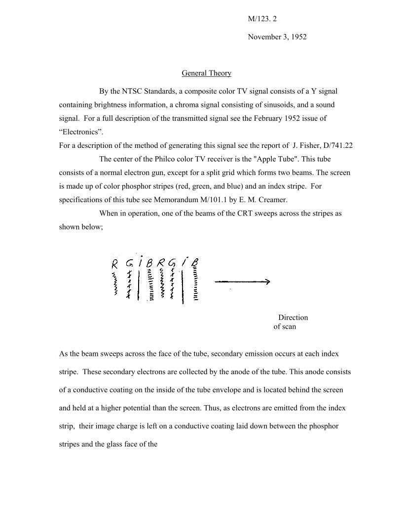
When in operation, one of the beams of the CRT sweeps across the stripes as
shown below;
Direction of scan
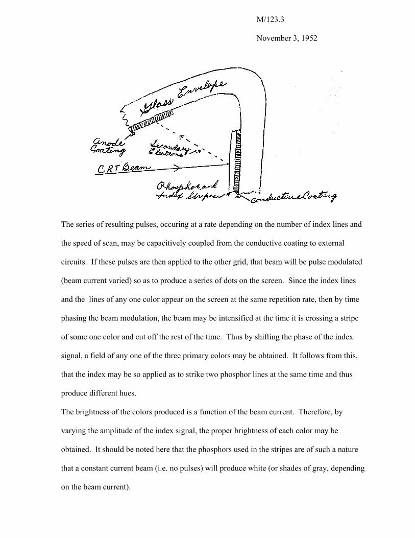
As the beam sweeps across the face of the tube, secondary emission occurs at each index
stripe. These secondary electrons are collected by the anode of the tube. This anode consists
of a conductive coating on the inside of the tube envelope and is located behind the screen
and held at a higher potential than the screen. Thus, as electrons are emitted from the index
strip, their image charge is left on a conductive coating laid down between the phosphor
stripes and the glass face of the
M/123.3
November 3, 1952
The series of resulting pulses, occuring at a rate depending on the number of index lines and
the speed of scan, may be capacitively coupled from the conductive coating to external
circuits. If these pulses are then applied to the other grid, that beam will be pulse modulated
(beam current varied) so as to produce a series of dots on the screen. Since the index lines
and the lines of any one color appear on the screen at the same repetition rate, then by time
phasing the beam modulation, the beam may be intensified at the time it is crossing a stripe
of some one color and cut off the rest of the time. Thus by shifting the phase of the index
signal, a field of any one of the three primary colors may be obtained. It follows from this,
that the index may be so applied as to strike two phosphor lines at the same time and thus
produce different hues.
The brightness of the colors produced is a function of the beam current. Therefore, by
varying the amplitude of the index signal, the proper brightness of each color may be
obtained. It should be noted here that the phosphors used in the stripes are of such a nature
that a constant current beam (i.e. no pulses) will produce white (or shades of gray, depending
on the beam current).
M/123.4
November 3, 1952
Since either beam sweeping across the screen will produce index signals, some
method of separating the index needed to produce color signals, and index formed when
producing a picture, must be used. Thus, one beam is used for obtaining index signal (the
"pilot beam”). The pilot beam is modulated at its grid with a 31.5 mc carrier, so that the
index information formed at the screen is 31.5 7 mc (the index pulses occur at a 7 mc rate).
Thus an amplifier designed to pick off the upper side-band of this signal (38.5 mc) may be
used to obtain the index information free from the 7 mc index formed by the writing beam.
31.5 mc pilot carrier is used because:
1) This frequency lies midway between the 4th and 5th harmonics of 7 mc. 2) There is less interference at 38.5 mc than other possible frequencies from outside
signal sources. 3) A lower pilot carrier frequency is not used because of the objectionable beat
pattern formed with the stripe structure of the CRT screen; tube noise at low sideband frequencies tends to obscure the useful signal.
4) A higher pilot carrier frequency is not used because of the
delay due to transient time between index stripes and anode; at higher side-band frequencies the passband of the amplifier must be wider for a given sweep non- linearity.
5) It should be noted that, harmonics lower than the 5th of the 7 mc drive are fairly strong.
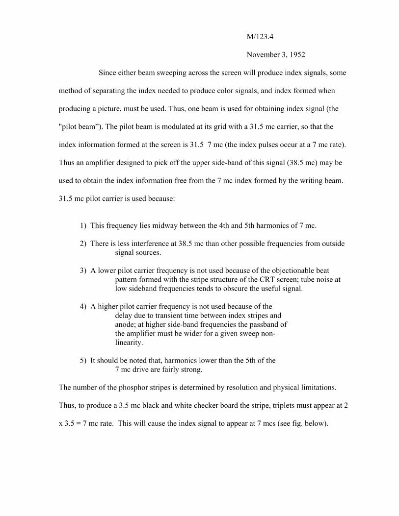
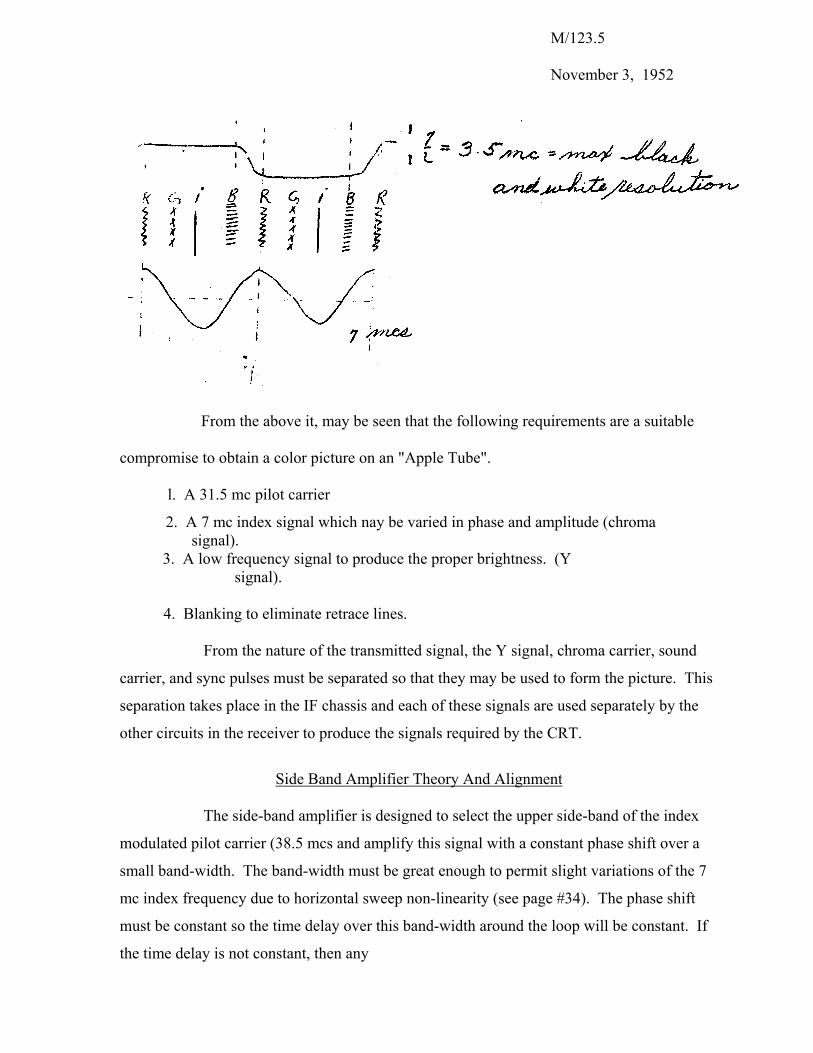
The number of the phosphor stripes is determined by resolution and physical limitations.
Thus, to produce a 3.5 mc black and white checker board the stripe, triplets must appear at 2
x 3.5 = 7 mc rate. This will cause the index signal to appear at 7 mcs (see fig. below).
M/123.5
November 3, 1952
From the above it, may be seen that the following requirements are a suitable
compromise to obtain a color picture on an "Apple Tube".
l. A 31.5 mc pilot carrier
2. A 7 mc index signal which nay be varied in phase and amplitude (chroma signal).
3. A low frequency signal to produce the proper brightness. (Y signal).
4. Blanking to eliminate retrace lines.
From the nature of the transmitted signal, the Y signal, chroma carrier, sound
carrier, and sync pulses must be separated so that they may be used to form the picture. This
separation takes place in the IF chassis and each of these signals are used separately by the
other circuits in the receiver to produce the signals required by the CRT.
Side Band Amplifier Theory And Alignment
The side-band amplifier is designed to select the upper side-band of the index
modulated pilot carrier (38.5 mcs and amplify this signal with a constant phase shift over a
small band-width. The band-width must be great enough to permit slight variations of the 7
mc index frequency due to horizontal sweep non-linearity (see page #34). The phase shift
must be constant so the time delay over this band-width around the loop will be constant. If
the time delay is not constant, then any
M/123.6
November 3, 1952
shift in index frequency will produce a phase shift in the index which will, in turn produce an
incorrect color on the screen of the CRT. No unmodulated 31.5 mc or 7 mc must be
permitted to reach the first stage where it can mix to produce 38.5 mcs. This undesirable 38.5
mc would also produce incorrect colors on the CRT. To obtain this desired result, a pole
diagram consisting of 2 poles, one superimposed on the other, and a zero, all at the resonant
frequency of 38.5 mcs, is used in the design of each stage. The damping of the zero is one
half that of the poles. (see Appendix A)
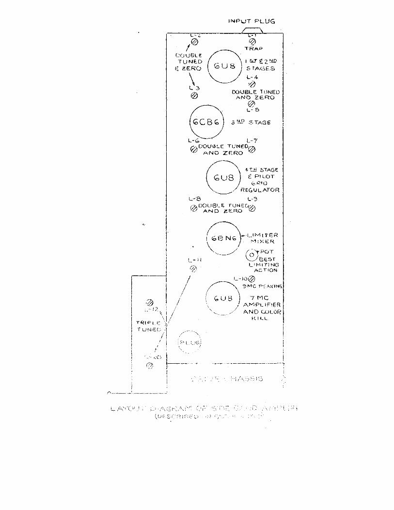
The input stage, a grounded grid amplifier, is tuned to 38.5 mc. There is a 31.5
trap in series with the input. The next four stages are all similar and embody the pole
diagram described above. To align the side-band amplifier, it is necessary to first neutralize
each stage by itself. After the stages are neutralized the 31.5 mc trap should
be aligned by tuning for minimum output when a 31.5 mc signal is applied to the input of the
side-band amplifier and a detector placed in the plate circuit of the first amplifier.
If the tuning of all of the other circuits is close to 38.5 mc, a signal of 38.5 mc
modulated with audio, may be fed into the input of the side-band amplifier, and a low
impedance detector placed at the output of the 6BN6 limiter (from plate to ground), the 4
traps are then tuned for minimum output, and the 4 plate tanks and input circuit are tuned for
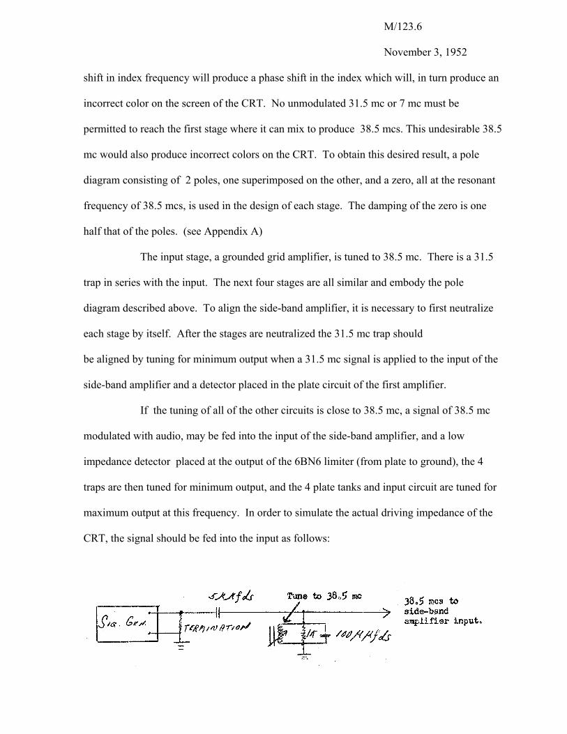
maximum output at this frequency. In order to simulate the actual driving impedance of the
CRT, the signal should be fed into the input as follows:
M/l23. 7
November 3, 1952
100 µvolts input would give 8 volts peak to peak at the grid of the 6BN6.
If the circuits are not tuned near 38.5 mc it is necessary to align each stage
individually so that it is near 38.5 mc, and then proceed as above. When the a1ignment has
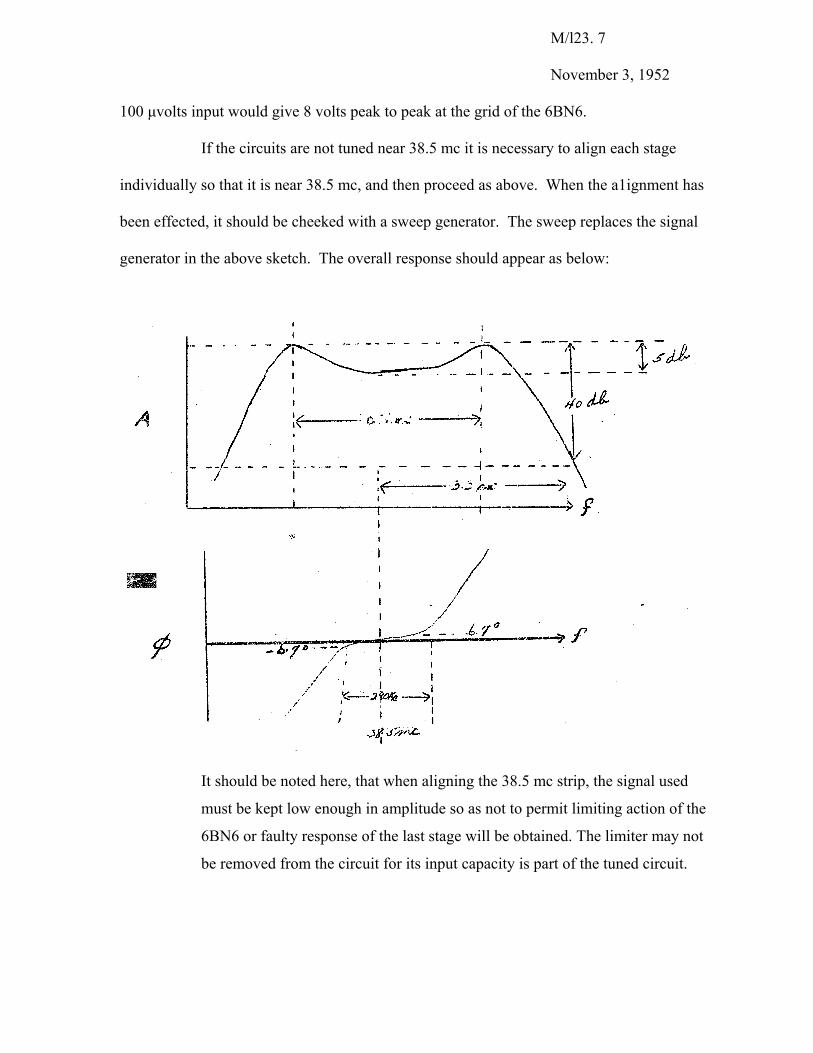
been effected, it should be cheeked with a sweep generator. The sweep replaces the signal
generator in the above sketch. The overall response should appear as below:
It should be noted here, that when aligning the 38.5 mc strip, the signal used
must be kept low enough in amplitude so as not to permit limiting action of the
6BN6 or faulty response of the last stage will be obtained. The limiter may not
be removed from the circuit for its input capacity is part of the tuned circuit.
M/123.8 November 3, 1952
The 38.5 mcs from the side-band amplifier strip is fed into the control grid of a 6BN6
and is limited there. This keeps the amplitude of all the index pulses constant so that the only
controlling influence on hue and saturation is from signals formed in the drive chassis.
Prediction
As stated previously, to obtain the proper hues on the screen of the CRT, the index
signal must be applied in the proper phase. Also, as shown in the discussion of the deflection
chassis, if the horizontal sweep is non-linear, then the index frequency will vary. Since the
horizontal sweep is non-linear, and therefore the index frequency is variable, a circuit must be
employed to keep the time-phase around the loop constant.
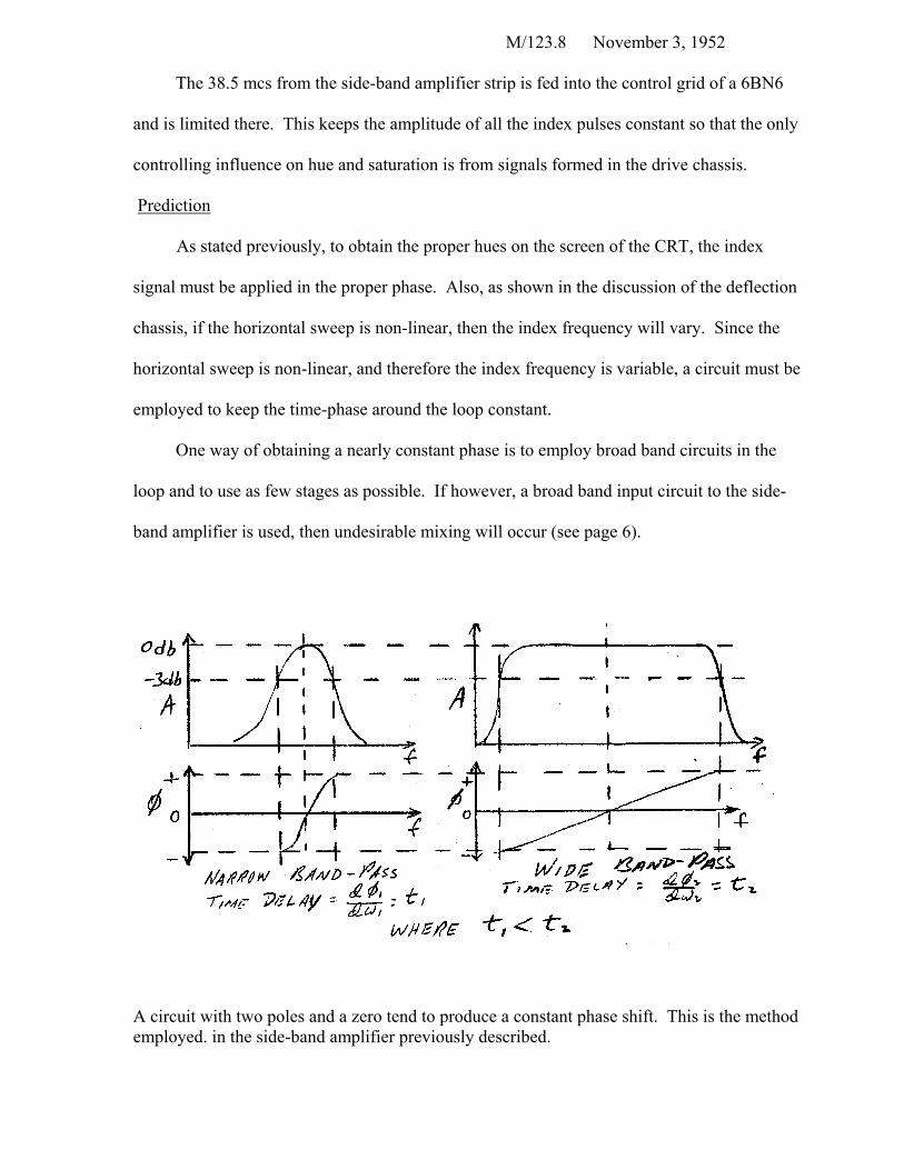
One way of obtaining a nearly constant phase is to employ broad band circuits in the
loop and to use as few stages as possible. If however, a broad band input circuit to the side-
band amplifier is used, then undesirable mixing will occur (see page 6).
A circuit with two poles and a zero tend to produce a constant phase shift. This is the method employed. in the side-band amplifier previously described.
M/123.9 November 3, 1952
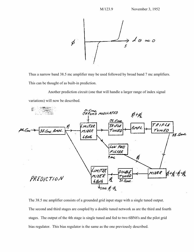
Thus a narrow band 38.5 mc amplifier may be used followed by broad band 7 mc amplifiers.
This can be thought of as built-in prediction.
Another prediction circuit (one that will handle a larger range of index signal
variations) will now be described.
The 38.5 mc amplifier consists of a grounded grid input stage with a single tuned output.
The second and third stages are coupled by a double tuned network as are the third and fourth
stages. The output of the 4th stage is single tuned and fed to two 6BN6's and the pilot grid
bias regulator. This bias regulator is the same as the one previously described.
M/123.10 November 3, 1952
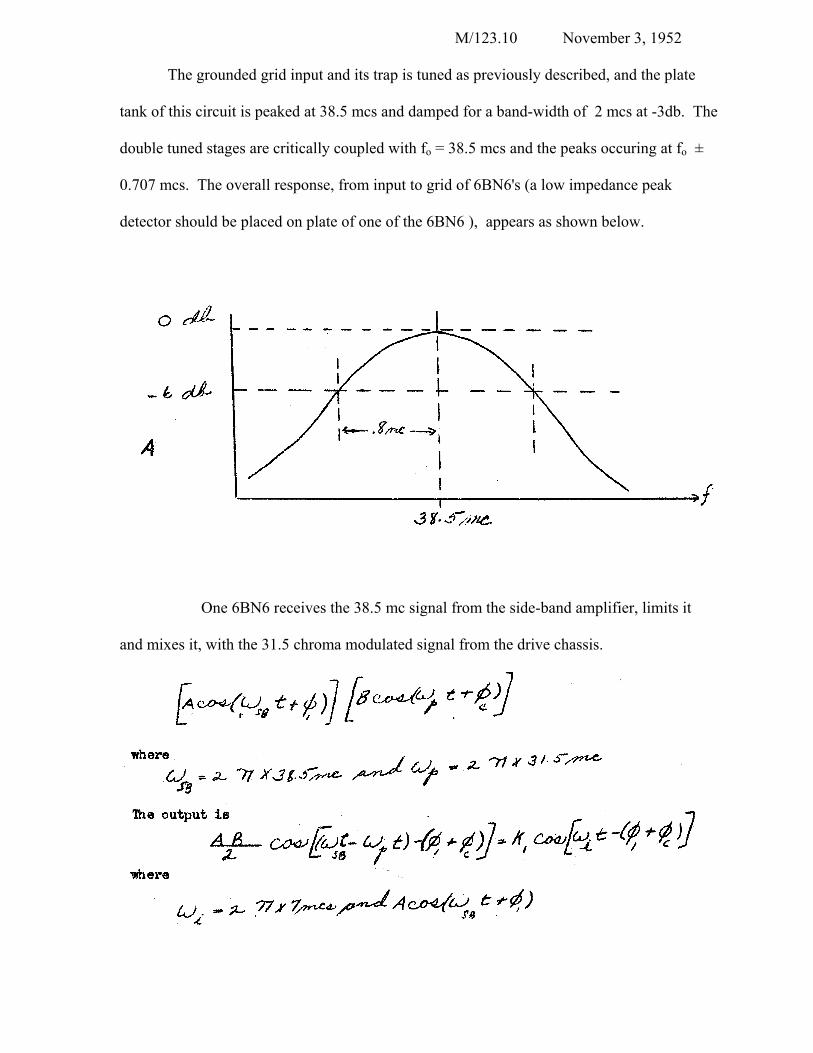
The grounded grid input and its trap is tuned as previously described, and the plate
tank of this circuit is peaked at 38.5 mcs and damped for a band-width of 2 mcs at -3db. The
double tuned stages are critically coupled with fo = 38.5 mcs and the peaks occuring at fo ±
0.707 mcs. The overall response, from input to grid of 6BN6's (a low impedance peak
detector should be placed on plate of one of the 6BN6 ), appears as shown below.
One 6BN6 receives the 38.5 mc signal from the side-band amplifier, limits it
and mixes it, with the 31.5 chroma modulated signal from the drive chassis.
M/123.11 November 3, 1952
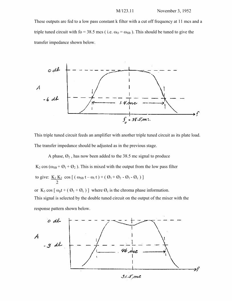
These outputs are fed to a low pass constant k filter with a cut off frequency at 11 mcs and a
triple tuned circuit with fo = 38.5 mcs ( i.e. ωO = ωSB ). This should be tuned to give the
transfer impedance shown below.
This triple tuned circuit feeds an amplifier with another triple tuned circuit as its plate load.
The transfer impedance should be adjusted as in the previous stage.
A phase, Ø2 , has now been added to the 38.5 mc signal to produce
K2 cos (ωSB + Ø1 + Ø2 ). This is mixed with the output from the low pass filter
to give: K1 K2 cos [ ( ωSB t – ωi t ) + ( Ø1 + Ø2 - Ø1 - Øc ) ] 2
or K3 cos [ ωpt + ( Ø1 + Øc ) ] where Øc is the chroma phase information.
This signal is selected by the double tuned circuit on the output of the mixer with the
response pattern shown below.
M/123.12 November 3, 1952
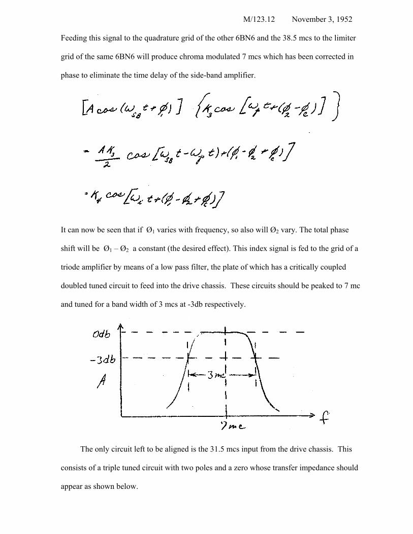
Feeding this signal to the quadrature grid of the other 6BN6 and the 38.5 mcs to the limiter
grid of the same 6BN6 will produce chroma modulated 7 mcs which has been corrected in
phase to eliminate the time delay of the side-band amplifier.
It can now be seen that if Ø1 varies with frequency, so also will Ø2 vary. The total phase
shift will be Ø1 – Ø2 a constant (the desired effect). This index signal is fed to the grid of a
triode amplifier by means of a low pass filter, the plate of which has a critically coupled
doubled tuned circuit to feed into the drive chassis. These circuits should be peaked to 7 mc
and tuned for a band width of 3 mcs at -3db respectively.
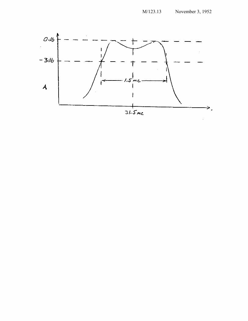
The only circuit left to be aligned is the 31.5 mcs input from the drive chassis. This
consists of a triple tuned circuit with two poles and a zero whose transfer impedance should
appear as shown below.
M/123.13 November 3, 1952
M/123.14 November 3, 1952
Pilot Beam Regulation
The index amplitude should be held constant on a long time basis also. This is
to prevent desaturation due to high levels of pilot beam current, or too little index to permit
limiting at the 6BN6. Thus, variations of the cutoff bias of the CRT due to ageing are
compensated for by a pilot beam regulator. Some of the non-limited 38.5 mcs is rectified and
supplied to the grid of the triode regulator. As the bias on this stage varies, varying the
current through the tube, the bias on the pilot grid of the CRT is also varied so as to
compensate for a change in index amplitude. It should be noted that the time constants of this
circuit at present are such as to permit regulation only over a period greater than a frame rate.
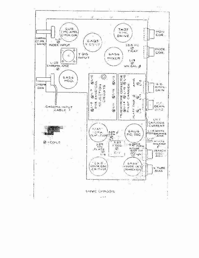
Theory And Alignment Behind Drive Chassis
To the index information must now be added chroma information to obtain the desired
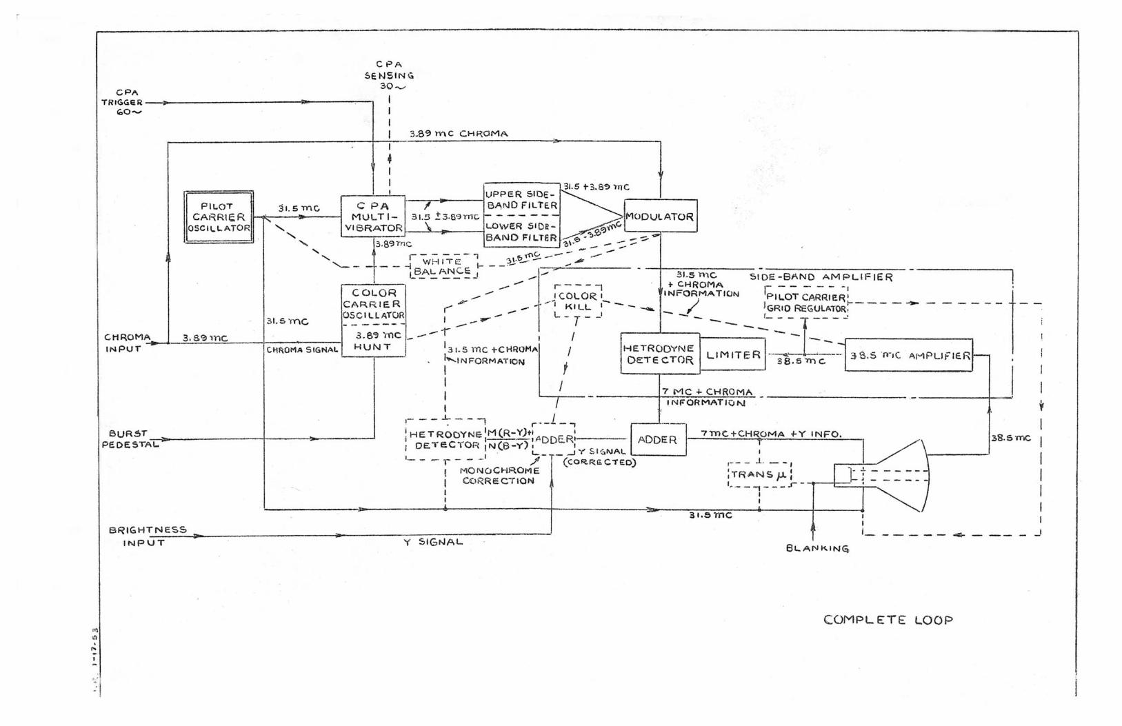
picture. This is done by means of a signal from the drive chassis, so an analysis of this unit
will follow.
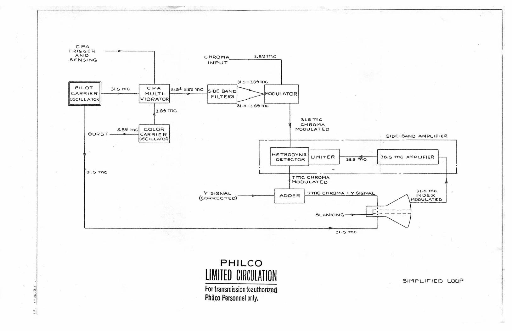
The drive chassis must supply pilot carrier, CPA demodulation, monochrome
correction, and chroma modulated pilot carrier for the side-band amplifier. For a description
of basic reasons for, and method of obtaining monochrome correction see Report D/739, by
S. W. Moulton.
From the IF chassis the 3.89 mc chroma signal is supplied to the drive chassis,
Here it is used to modulate the pilot carrier. This pilot carrier with its color information is
sent to the side-band amplifier and converted to chroma modulated index signal. The index
signal, phase and amplitude modulated, is fed into the drive chassis, added to Y signal which
has been monochrome corrected and applied to the writing grid of the CRT.
M/123.15 November 3, 1952
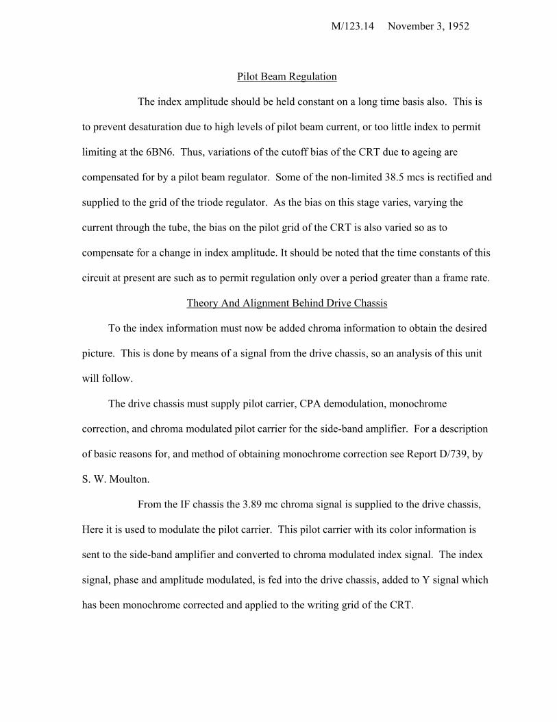
The first circuit to be aligned is the 31.5 mc pilot carrier oscillator (6AU6). This
is an EC Colpitts circuit, selected for stability and ease of changing the position of the
cathode to grid tap by merely changing the ratios of the grid tank condensers. The circuit is
set on frequency by varying the inductance on the grid tank (L-5) and checking frequency
with a frequency meter.
The 2 µh plate peaking coil (L-1) is then tuned for maximum output (about 3 volts peak) by
placing a low capacity detector on the cathode of the 12AT7 multivibrator. If tuning the plate
circuit varies the oscillator frequency by more then ± 20 kc, the wiring is causing too much
coupling between plate and grid circuits.
M/123. l6 November 3, 1952
Another detector is placed on the pilot carrier grid of the CRT and the 4 µh (L-2)
and 2 µh (L-3) inductances are tuned for maximum detector output, The third coil of this
triple tuned network is placed all the way at one end of its range (Slug out). This third coil
(L-4) (located on trans-mu plate) is a phase shifting device and will be adjusted later.
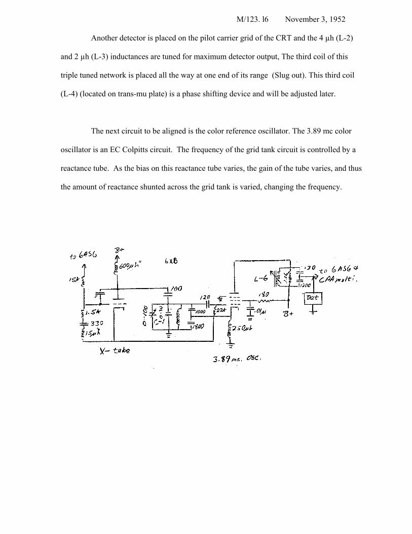
The next circuit to be aligned is the color reference oscillator. The 3.89 mc color
oscillator is an EC Colpitts circuit. The frequency of the grid tank circuit is controlled by a
reactance tube. As the bias on this reactance tube varies, the gain of the tube varies, and thus
the amount of reactance shunted across the grid tank is varied, changing the frequency.
M/123.17 November 3, 1952
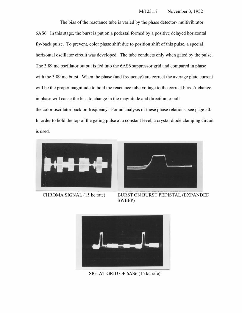
The bias of the reactance tube is varied by the phase detector- multivibrator
6AS6. In this stage, the burst is put on a pedestal formed by a positive delayed horizontal
fly-back pulse. To prevent, color phase shift due to position shift of this pulse, a special
horizontal oscillator circuit was developed. The tube conducts only when gated by the pulse.
The 3.89 mc oscillator output is fed into the 6AS6 suppressor grid and compared in phase
with the 3.89 mc burst. When the phase (and frequency) are correct the average plate current
will be the proper magnitude to hold the reactance tube voltage to the correct bias. A change
in phase will cause the bias to change in the magnitude and direction to pull
the color oscillator back on frequency. For an analysis of these phase relations, see page 50.
In order to hold the top of the gating pulse at a constant level, a crystal diode clamping circuit
is used.
CHROMA SIGNAL (15 kc rate) BURST ON BURST PEDISTAL (EXPANDED
SWEEP)
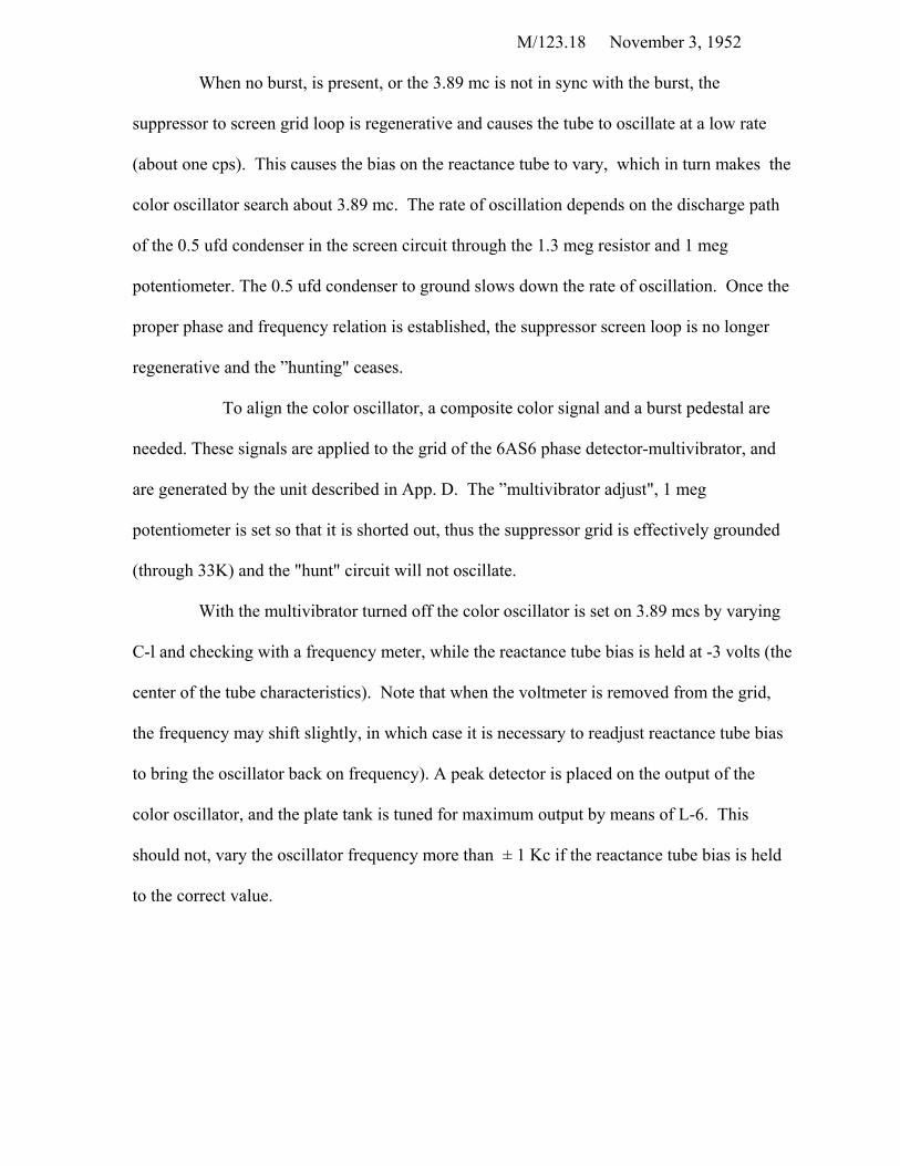
SIG. AT GRID OF 6AS6 (15 kc rate)
M/123.18 November 3, 1952
When no burst, is present, or the 3.89 mc is not in sync with the burst, the
suppressor to screen grid loop is regenerative and causes the tube to oscillate at a low rate
(about one cps). This causes the bias on the reactance tube to vary, which in turn makes the
color oscillator search about 3.89 mc. The rate of oscillation depends on the discharge path
of the 0.5 ufd condenser in the screen circuit through the 1.3 meg resistor and 1 meg
potentiometer. The 0.5 ufd condenser to ground slows down the rate of oscillation. Once the
proper phase and frequency relation is established, the suppressor screen loop is no longer
regenerative and the ”hunting" ceases.
To align the color oscillator, a composite color signal and a burst pedestal are
needed. These signals are applied to the grid of the 6AS6 phase detector-multivibrator, and
are generated by the unit described in App. D. The ”multivibrator adjust", 1 meg
potentiometer is set so that it is shorted out, thus the suppressor grid is effectively grounded
(through 33K) and the "hunt" circuit will not oscillate.
With the multivibrator turned off the color oscillator is set on 3.89 mcs by varying
C-l and checking with a frequency meter, while the reactance tube bias is held at -3 volts (the
center of the tube characteristics). Note that when the voltmeter is removed from the grid,
the frequency may shift slightly, in which case it is necessary to readjust reactance tube bias
to bring the oscillator back on frequency). A peak detector is placed on the output of the
color oscillator, and the plate tank is tuned for maximum output by means of L-6. This
should not, vary the oscillator frequency more than ± 1 Kc if the reactance tube bias is held
to the correct value.
M/123.19 November 3, 1952
It should be noted there are two variable condensers in the grid tank - one a course
control and the other a padder. The oscillator should be placed on frequency with the course
control and with the padder in the middle of its range. This oscillator has been stabilized by
using an air core inductance, negative temperature coefficient compensating capacitors, and a
combination of reactance tube and oscillator circuits of such a nature so as to compensate for
line voltage fluctuations.
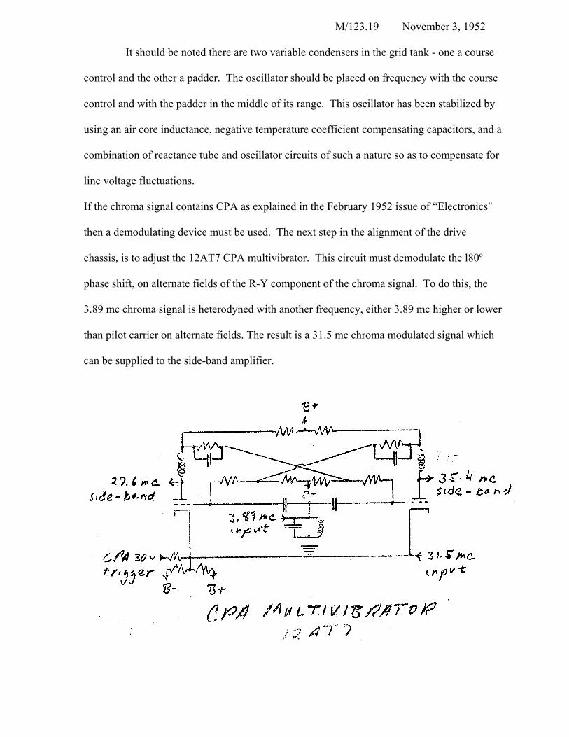
If the chroma signal contains CPA as explained in the February 1952 issue of “Electronics"
then a demodulating device must be used. The next step in the alignment of the drive
chassis, is to adjust the 12AT7 CPA multivibrator. This circuit must demodulate the l80º
phase shift, on alternate fields of the R-Y component of the chroma signal. To do this, the
3.89 mc chroma signal is heterodyned with another frequency, either 3.89 mc higher or lower
than pilot carrier on alternate fields. The result is a 31.5 mc chroma modulated signal which
can be supplied to the side-band amplifier.
M/123. 20
November 3, 1952
The CPA multivibrator 12AT7 takes the pilot carrier frequency (at its cathode)
and mixes it with the color reference carrier frequency (on the control grid) to get the two
side-bands of 31.5 ± 3.89 mcs. Analysis of the CPA multivibrator and its associated circuits
appears on page 48. The CPA trigger causes the Eccles-Jordan multivibrator to flip-flop at a
30 cps rate, selecting either the upper or the lower side-band. This trigger is a 60 cps positive
pulse applied to the cathode (about 15 volts peak to peak), each pulse causing the circuit to
flip. When out of phase an additional pulse is supplied from the deflection chassis to the
cathode of the multivibrator causing it to flip during the vertical scan and hence to change
phase. Some 30 cps square wave is supplied from one of the plates of the multivibrator to
the deflection chassis so that "in phase” and "out of phase" information may be obtained.
(See page 38).
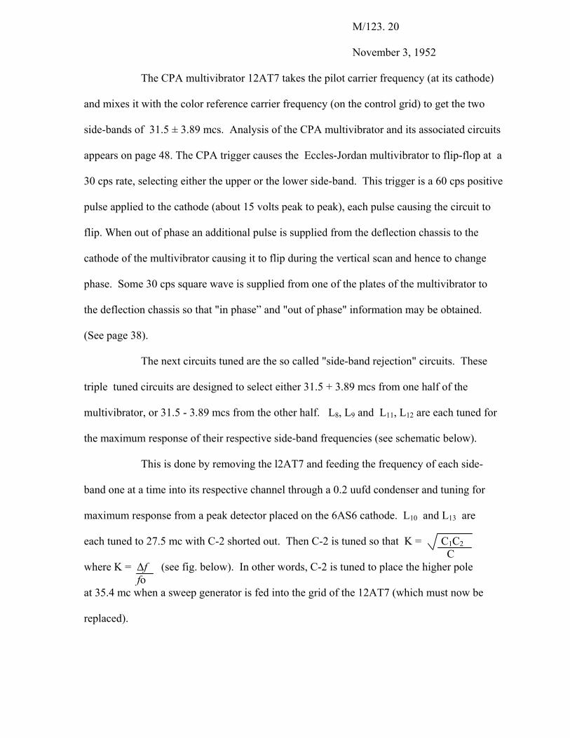
The next circuits tuned are the so called "side-band rejection" circuits. These
triple tuned circuits are designed to select either 31.5 + 3.89 mcs from one half of the
multivibrator, or 31.5 - 3.89 mcs from the other half. L8, L9 and L11, L12 are each tuned for
the maximum response of their respective side-band frequencies (see schematic below).
This is done by removing the l2AT7 and feeding the frequency of each side-
band one at a time into its respective channel through a 0.2 uufd condenser and tuning for
maximum response from a peak detector placed on the 6AS6 cathode. L10 and L13 are
each tuned to 27.5 mc with C-2 shorted out. Then C-2 is tuned so that K = C1C2 C
where K = ∆f (see fig. below). In other words, C-2 is tuned to place the higher pole fo at 35.4 mc when a sweep generator is fed into the grid of the 12AT7 (which must now be replaced).
M/123. 21
November 3, 1952
Finally the color oscillator (6X8) is removed and a sweep generator is fed into the
grids of the 12AT7. The coils L8 through L12 are then touched up for maximum and even
amplitudes, producing the pattern shown below
M/123. 22
November 3, 1952
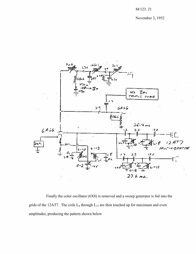
The grid tank circuit of the 12AT7 should be tuned to 3.89 mc with a grid dip meter, and the
peaking coil in the plate of the 6AS6 leading to the side-band amplifier should be tuned to
31.5 mcs with a grid dip meter. These adjustments are only approximate, the first being
given a final touch up to produce proper colors on the CRT and the latter being aligned in
conjunction with the side-hand amplifier.
M/123.23 November 3, 1952
The output of the ”side-band" rejection circuits feed the control grid of the 6AS6,
3.89 mc color information is applied to the suppressor grid, and plate tuned to 31.5 mc. The
31.5 mc output modulated with chroma information and freed of CPA effects is fed to the
monochrome correction circuit and the side-band amplifier where the chroma is combined
with the 38.5 mc pilot carrier-index side-band to produce the 7 mc drive signal.
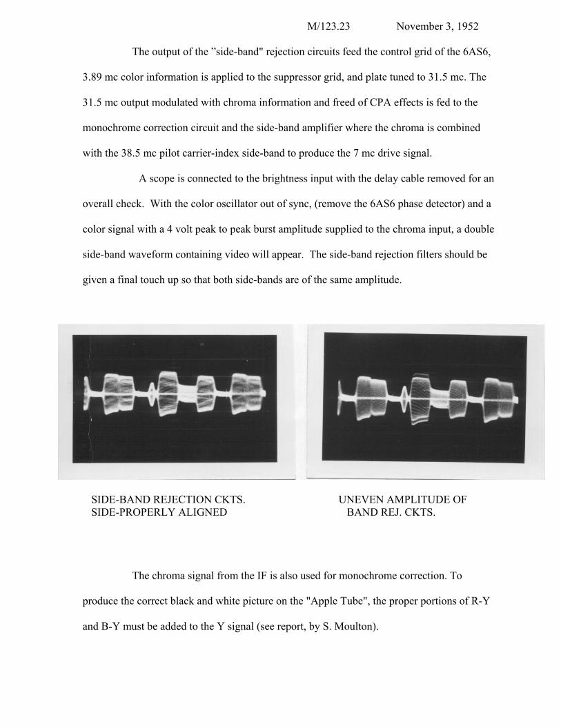
A scope is connected to the brightness input with the delay cable removed for an
overall check. With the color oscillator out of sync, (remove the 6AS6 phase detector) and a
color signal with a 4 volt peak to peak burst amplitude supplied to the chroma input, a double
side-band waveform containing video will appear. The side-band rejection filters should be
given a final touch up so that both side-bands are of the same amplitude.
SIDE-BAND REJECTION CKTS. UNEVEN AMPLITUDE OF SIDE-PROPERLY ALIGNED BAND REJ. CKTS.
The chroma signal from the IF is also used for monochrome correction. To
produce the correct black and white picture on the "Apple Tube", the proper portions of R-Y
and B-Y must be added to the Y signal (see report, by S. Moulton).
M/123. 24
November 3, 1952
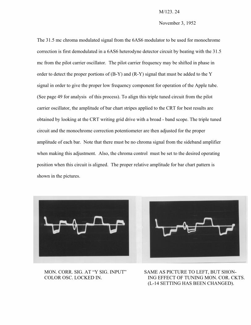
The 31.5 mc chroma modulated signal from the 6AS6 modulator to be used for monochrome
correction is first demodulated in a 6AS6 heterodyne detector circuit by beating with the 31.5
mc from the pilot carrier oscillator. The pilot carrier frequency may be shifted in phase in
order to detect the proper portions of (B-Y) and (R-Y) signal that must be added to the Y
signal in order to give the proper low frequency component for operation of the Apple tube.
(See page 49 for analysis of this process). To align this triple tuned circuit from the pilot
carrier oscillator, the amplitude of bar chart stripes applied to the CRT for best results are
obtained by looking at the CRT writing grid drive with a broad - band scope. The triple tuned
circuit and the monochrome correction potentiometer are then adjusted for the proper
amplitude of each bar. Note that there must be no chroma signal from the sideband amplifier
when making this adjustment. Also, the chroma control must be set to the desired operating
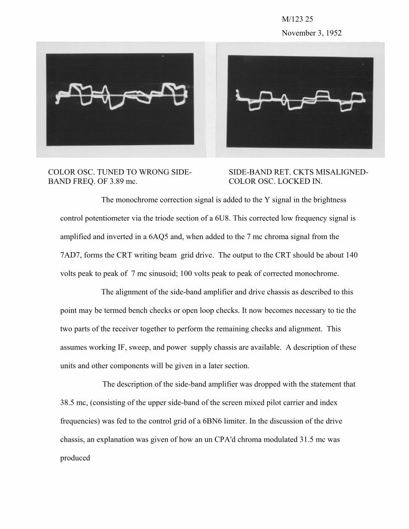
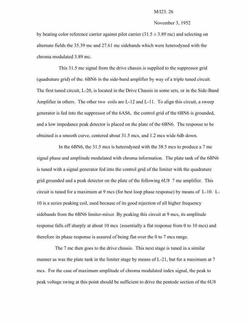
position when this circuit is aligned. The proper relative amplitude for bar chart pattern is
shown in the pictures.
MON. CORR. SIG. AT “Y SIG. INPUT” SAME AS PICTURE TO LEFT, BUT SHON- COLOR OSC. LOCKED IN. ING EFFECT OF TUNING MON. COR. CKTS. (L-14 SETTING HAS BEEN CHANGED).
M/123 25
November 3, 1952
COLOR OSC. TUNED TO WRONG SIDE- SIDE-BAND RET. CKTS MISALIGNED- BAND FREQ. OF 3.89 mc. COLOR OSC. LOCKED IN.
The monochrome correction signal is added to the Y signal in the brightness
control potentiometer via the triode section of a 6U8. This corrected low frequency signal is
amplified and inverted in a 6AQ5 and, when added to the 7 mc chroma signal from the
7AD7, forms the CRT writing beam grid drive. The output to the CRT should be about 140
volts peak to peak of 7 mc sinusoid; 100 volts peak to peak of corrected monochrome.
The alignment of the side-band amplifier and drive chassis as described to this
point may be termed bench checks or open loop checks. It now becomes necessary to tie the
two parts of the receiver together to perform the remaining checks and alignment. This
assumes working IF, sweep, and power supply chassis are available. A description of these
units and other components will be given in a later section.
The description of the side-band amplifier was dropped with the statement that
38.5 mc, (consisting of the upper side-band of the screen mixed pilot carrier and index
frequencies) was fed to the control grid of a 6BN6 limiter. In the discussion of the drive
chassis, an explanation was given of how an un CPA'd chroma modulated 31.5 mc was
produced
M/l23. 26
November 3, 1952
by beating color reference carrier against pilot carrier (31.5 ± 3.89 mc) and selecting on
alternate fields the 35.39 mc and 27.61 mc sidebands which were heterodyned with the
chroma modulated 3.89 mc.
This 31.5 mc signal from the drive chassis is supplied to the suppressor grid
(quadrature grid) of the. 6BN6 in the side-band amplifier by way of a triple tuned circuit.
The first tuned circuit, L-20, is located in the Drive Chassis in some sets, or in the Side-Band
Amplifier in others. The other two coils are L-12 and L-11. To align this circuit, a sweep
generator is fed into the suppressor of the 6AS6, the control grid of the 6BN6 is grounded,
and a low impedance peak detector is placed on the plate of the 6BN6. The response to be
obtained is a smooth curve, centered about 31.5 mcs, and 1.2 mcs wide 6db down.
In the 6BN6, the 31.5 mcs is heterodyned with the 38.5 mcs to produce a 7 mc
signal phase and amplitude modulated with chroma information. The plate tank of the 6BN6
is tuned with a signal generator fed into the control grid of the limiter with the quadrature
grid grounded and a peak detector on the plate of the following 6U8 7 mc amplifier. This
circuit is tuned for a maximum at 9 mcs (for best loop phase response) by means of L-10. L-
10 is a series peaking coil, used because of its good rejection of all higher frequency
sidebands from the 6BN6 limiter-mixer. By peaking this circuit at 9 mcs, its amplitude
response falls off sharply at about 10 mcs {essentially a flat response from 0 to 10 mcs) and
therefore its phase response is assured of being flat over the 0 to 7 mcs range.
The 7 mc then goes to the drive chassis. This next stage is tuned in a similar
manner as was the plate tank in the limiter stage by means of L-21, but for a maximum at 7
mcs. For the case of maximum amplitude of chroma modulated index signal, the peak to
peak voltage swing at this point should be sufficient to drive the pentode section of the 6U8
M/123.27
November 3, 1952
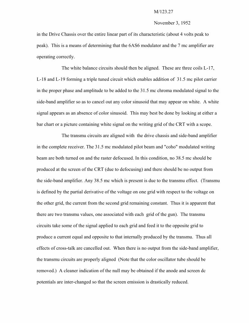
in the Drive Chassis over the entire linear part of its characteristic (about 4 volts peak to
peak). This is a means of determining that the 6AS6 modulator and the 7 mc amplifier are
operating correctly.
The white balance circuits should then be aligned. These are three coils L-17,
L-18 and L-19 forming a triple tuned circuit which enables addition of 31.5 mc pilot carrier
in the proper phase and amplitude to be added to the 31.5 mc chroma modulated signal to the
side-band amplifier so as to cancel out any color sinusoid that may appear on white. A white
signal appears as an absence of color sinusoid. This may best be done by looking at either a
bar chart or a picture containing white signal on the writing grid of the CRT with a scope.
The transmu circuits are aligned with the drive chassis and side-band amplifier
in the complete receiver. The 31.5 mc modulated pilot beam and "coho" modulated writing
beam are both turned on and the raster defocused. In this condition, no 38.5 mc should be
produced at the screen of the CRT (due to defocusing) and there should be no output from
the side-band amplifier. Any 38.5 mc which is present is due to the transmu effect. (Transmu
is defined by the partial derivative of the voltage on one grid with respect to the voltage on
the other grid, the current from the second grid remaining constant. Thus it is apparent that
there are two transmu values, one associated with each grid of the gun). The transmu
circuits take some of the signal applied to each grid and feed it to the opposite grid to
produce a current equal and opposite to that internally produced by the transmu. Thus all
effects of cross-talk are cancelled out. When there is no output from the side-band amplifier,
the transmu circuits are properly aligned (Note that the color oscillator tube should be
removed.) A cleaner indication of the null may be obtained if the anode and screen dc
potentials are inter-changed so that the screen emission is drastically reduced.
M/123. 28
23 November 3, 1952
The final circuit to be aligned is the triple tuned coupling circuit (L-2, L-3, and L-4)
between the pilot carrier oscillator and the pilot grid of the CRT. This circuit is set so the phase
of the pilot carrier is such as to give the proper colors of the color picture. Thus, this constitutes
a master phase control. It is actually changing the phase of the input signal to the side-band
amplifier with respect to the phase of the 31.5 mc chroma modulated signal from the 6AS6
modulator. For an analysis of the phase relations around the loop, see page 47 .
Diode correction in the chroma drive channel is to set the DC level of the 7 mc
sinusoid with respect to cutoff on the writing beam so that the saturation of the colors will be
pleasing on various test slides. There is a theoretically correct value for this adjustment, but
subjective evaluations have shown it to be relatively non critical.
One additional circuit, not necessary for the production of a color picture, and not
needing any operational adjustments, is the color quench. This device is a means of eliminating
any chroma signal from reaching the CRT when color sync is lost or when receiving a
monochrome broadcast. Color quench information is supplied from the search oscillator and
phase detector in the drive chassis (see page 18 ). When this multivibrator is not sweeping (i.e.
color oscillator is in sync.) no signal is supplied to the color quench grid and the tube is held cut
off. When out of color sync, the multivibrator action causes the color quench tube to conduct,
cutting off the 7 mc amplifier in the side-band amplifier and the monochrome correction circuit
in the drive chassis. (see page 24 ).
Magnetic Lens Alignment
As stated previously, the direction of scan is perpendicular to the direction of the phosphor
stripes on the screen of the CRT. To obtain a color
M/123. 29
November 3, 1952
(for example, any one of the primary colors) the cross sectional size of the electron beam (i.e. the
spot size and its elongation due to motion) must be small enough to strike only one phosphor
stripe at a time. This means that the focus coil must be carefully aligned for maximum color
saturation. Since the index information is to control the color information, the pilot carrier beam
must have a particular orientation with respect to the writing beam. This gives rise to the use of
a rotator coil to provide preferred positioning inspite of tube and component variations. The
yoke must be correctly positioned so the sweep will be perpendicular to the phosphor stripes.
The deflection yoke is aligned first and voltages needed are for the CRT filament,
anode, screen, and a variable bias on the two control grids. This bias should be able to cut the
beam off (-125 to -250 volts cut-off).
It is strongly recommended that wherever the tube is operated without normal
deflection fields in this series of alignment tests, a pulser unit be used to provide grid voltages so
that the screen will not be damaged. This pulser unit should provide substantially rectangular
pulses whose duty cycle is less than 5%. This means that the screen can be illuminated
adequately without danger of burning a hole in the phosphor material. The pulser unit
is not absolutely necessary when the beam is unfocused but no harm will be done if it is
connected through these tests and the danger of accidentally focusing the high current beam and
thus producing permanent screen burn is greatly reduced.
The first step is to obtain the geometrical position of the center of the unfocused and
undeflected spots. If these are not coincident it indicates a variation from optimum convergence
in the tube; then the position of the center of the writing bean spot is the reference. Before
attempting to find this position it is necessary to be sure that the yoke and focuser
M/123.30
November 3, 1952
have no residual magnetic field. It is recommended that both of those units be demagnetized in a
suitable low frequency AC field. In fact, should any doubt as to the magnetic condition of these
units exist it is preferable to leave them off the tube neck entirely until the position of the
unfocused and undeflected spot is obtained. Since precision techniques are used in aligning the
gun and neck on these Apple tubes the spot position just found should be within 1/2” of the
geometrical center of the tube. A position which is either at or beyond this limit invites
suspicion.
Next the axial position along with tube neck of the yoke and focuser unit should be
correctly adjusted. The yoke is pushed as far forward as it can go when radially symmetrical
about the tube neck. It is then pulled back toward the gun approximately 1/8” to provide for
motion in later adjustments. The edge of the focus unit is set between 1/4 and 1/2" from the
maximum and turn plane of the yoke. The clamp rings may now be tightened so that further
axial motion cannot take place. Yoke rotation is next adjusted. This is most conveniently
accomplished with a full size raster in reasonably good focus such that it can reproduce a color
rainbow when the tube is driven by a cohered 7 mc oscillator. Yoke rotation is adjusted until the
rainbow stripes are vertical and any pincushion which may remain is as symmetrical as possible.
Yoke rotation is now correct and no further adjustment of it is required.
Yoke tilt and radial translation are next on the list. To adjust these the focus unit is
again deenergized. The horizontal windings of the yoke are connected series bucking and a
power line frequency voltage (about 12 volts rms) is impressed on these windings only. A cross
pattern will be observed on the screen of the tube. The object of further adjustment is to obtain a
symmetrical cross whose center coincides with that of the unfocused, undeflected spot
previously located. This can be accomplished by the adjustment
M/123. 31
November 3, 1952
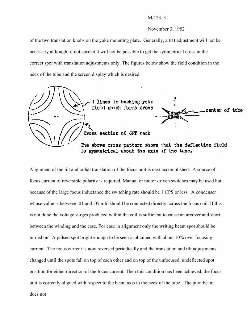
of the two translation knobs on the yoke mounting plate. Generally, a ti1t adjustment will not be
necessary although if not correct it will not be possible to get the symmetrical cross in the
correct spot with translation adjustments only. The figures below show the field condition in the
neck of the tube and the screen display which is desired.
Alignment of the tilt and radial translation of the focus unit is next accomplished. A source of
focus current of reversible polarity is required. Manual or motor driven switches may be used but
because of the large focus inductance the switching rate should be 1 CPS or less. A condenser
whose value is between .01 and .05 mfd should be connected directly across the focus coil. If this
is not done the voltage surges produced within the coil is sufficient to cause an arcover and short
between the winding and the case. For ease in alignment only the writing beam spot should be
turned on. A pulsed spot bright enough to be seen is obtained with about 10% over focusing
current. The focus current is now reversed periodically and the translation and tilt adjustments
changed until the spots fall on top of each other and on top of the unfocused, undeflected spot
position for either direction of the focus current. Then this condition has been achieved, the focus
unit is correctly aligned with respect to the beam axis in the neck of the tube. The pilot beam
does not
M/123. 32
November 3, 1952
require as great a resolution as the writing beam, hence the latter is favored in adjusting the
focus coil.
When the focus coil is properly oriented about the axis of the tube, the rotator coil is
also properly oriented as it is a part of the same unit. The only thing to be determined about the
rotator is the direction and magnitude of current flow through the coil so as to orient the spots in
the preferred position one above the other.
Rotation occurs in the focusing field because of the perpendicular force acting on
the off center beam electrons in the magnetic lens. This causes the electrons to move in the path
of a helix. Since the focused beam, as it leaves the focusing lens, leaves at the axis of the lens, a
tilted focuser will cause the spots to be off center on the screen.
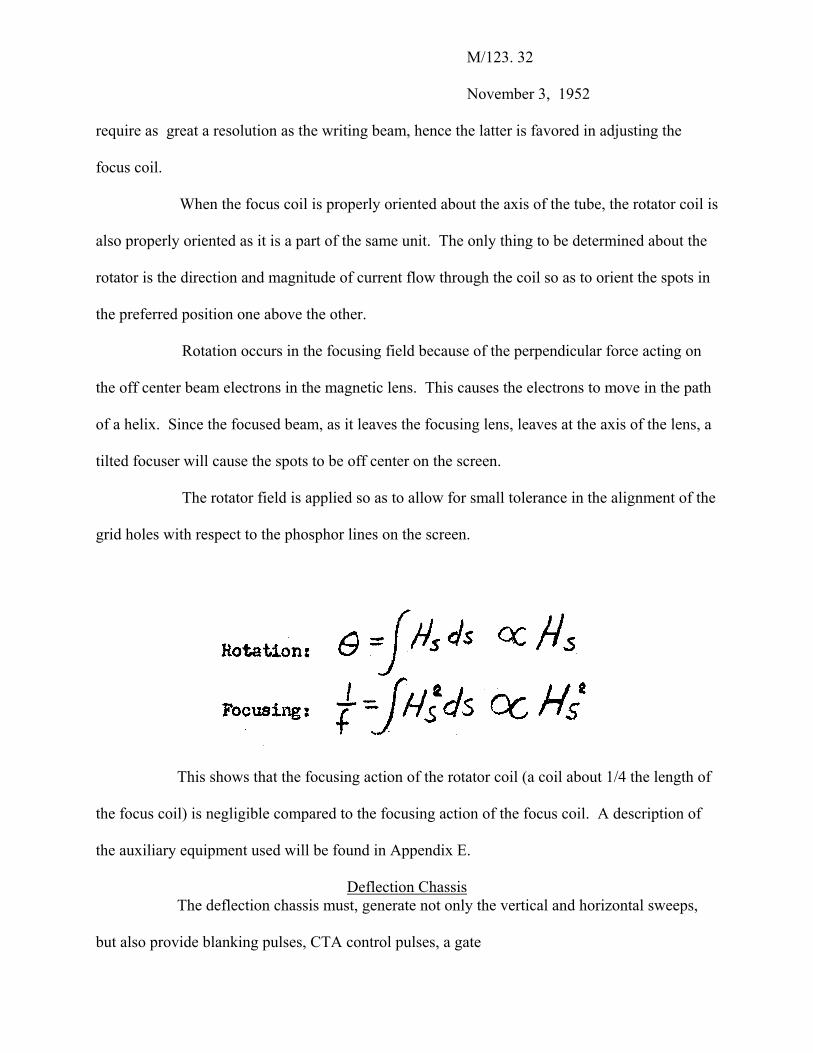
The rotator field is applied so as to allow for small tolerance in the alignment of the
grid holes with respect to the phosphor lines on the screen.
This shows that the focusing action of the rotator coil (a coil about 1/4 the length of
the focus coil) is negligible compared to the focusing action of the focus coil. A description of
the auxiliary equipment used will be found in Appendix E.
Deflection Chassis The deflection chassis must, generate not only the vertical and horizontal sweeps,
but also provide blanking pulses, CTA control pulses, a gate
M/123. 33
November 3, 1952
pulse for AGC, regulated focuser and rotator current, vertical dynamic focus current, color
reference burst gating burst pedestal), and CRT regulated high voltage.
The IF chassis supplies negative mixed sync (stripped from the video) at 10 volts
peak to peak. In the deflection chassis the sync signal is amplified, integrated and differentiated
to provide frame, field, and line sync for CPA, vertical and horizontal deflection. The vertical
sweep oscillator and amplifier are straightforward circuits, few changes having been made from
TV- 40 deflection circuits. The horizontal oscillator is controlled by means of an AFC circuit
which has been designed to give a small lock in range so that the flyback pulse can provide a
suitable burst gate which will remain under the burst signal as the horizontal hold control is
varied. The high voltage circuit has been separated from the horizontal output because of the
required horizontal linearity. The horizontal output circuits have been modified in the interest of
constant index frequency which is kept to within 3%.
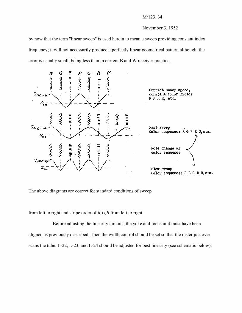
Assume a non-linear sweep. Then, the indexing signal will not be 7 mcs, but will be
higher for a fast sweep and lower for a slow sweep. This will tend to produce a color change
across the face of the tube. It will also mean that the side-band amplifier must have a wider band-
width and it will be more difficult to provide a constant phase shift within this pass band.
A cohered oscillator (see Appendix C) may be used to check the horizontal sweep
linearity. This is a 7 mc oscillator whose phase is cohered or adjusted by the deflection flyback
so that, each line starts off the same way. It is applied to the writing grid of the CRT. Since this
7 mcs is not phase or amplitude modulated, the raster should appear in only one color (if the
index frequency is also constant). A non-linear sweep will mean that the beam is not swept
across the screen at a constant rate and therefore a rainbow effect will be produced on the face of
the tube. It should be apparent
M/123. 34
November 3, 1952
by now that the term "linear sweep" is used herein to mean a sweep providing constant index
frequency; it will not necessarily produce a perfectly linear geometrical pattern although the
error is usually small, being less than in current B and W receiver practice.
The above diagrams are correct for standard conditions of sweep
from left to right and stripe order of R,G,B from left to right.
Before adjusting the linearity circuits, the yoke and focus unit must have been
aligned as previously described. Then the width control should be set so that the raster just over
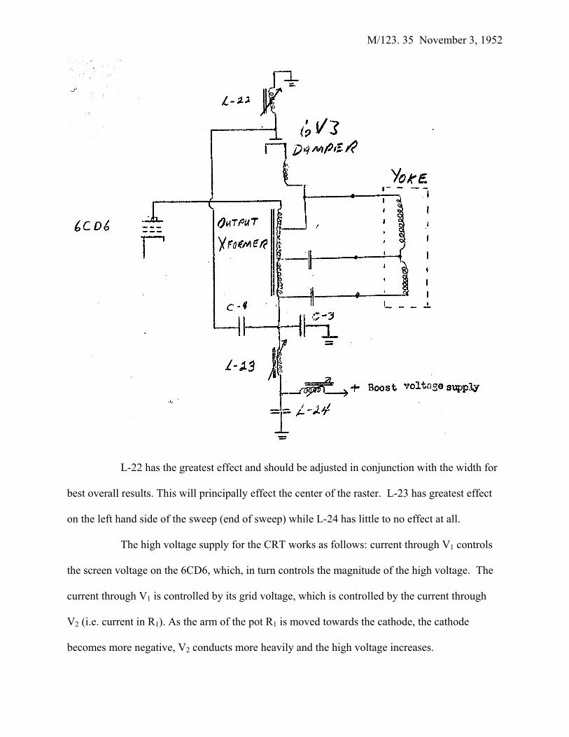
scans the tube. L-22, L-23, and L-24 should be adjusted for best linearity (see schematic below).
M/123. 35 November 3, 1952
L-22 has the greatest effect and should be adjusted in conjunction with the width for
best overall results. This will principally effect the center of the raster. L-23 has greatest effect
on the left hand side of the sweep (end of sweep) while L-24 has little to no effect at all.
The high voltage supply for the CRT works as follows: current through V1 controls
the screen voltage on the 6CD6, which, in turn controls the magnitude of the high voltage. The
current through V1 is controlled by its grid voltage, which is controlled by the current through
V2 (i.e. current in R1). As the arm of the pot R1 is moved towards the cathode, the cathode
becomes more negative, V2 conducts more heavily and the high voltage increases.
M/123.36 November 3, 1952
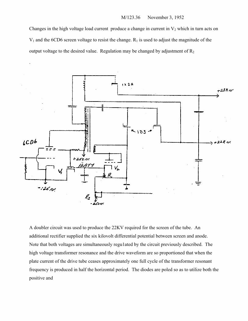
Changes in the high voltage load current produce a change in current in V2 which in turn acts on
V1 and the 6CD6 screen voltage to resist the change. R1 is used to adjust the magnitude of the
output voltage to the desired value. Regulation may be changed by adjustment of R2
.
A doubler circuit was used to produce the 22KV required for the screen of the tube. An
additional rectifier supplied the six kilovolt differential potential between screen and anode.
Note that both voltages are simultaneously regu1ated by the circuit previously described. The
high voltage transformer resonance and the drive waveform are so proportioned that when the
plate current of the drive tube ceases approximately one full cycle of the transformer resonant
frequency is produced in half the horizontal period. The diodes are poled so as to utilize both the
positive and
M/123.37 November 3, 1952
negative peaks of this ringing frequency; hence a full wave voltage doubler exists for the screen
voltage.
Considerable difficulty was encountered with heat rise and corona in the
transformer which was solved by casting the winding in a suitable casting resin (Araldite).
These materials offer hope of producing improved performance in high voltage supplies. The
use of a tripler circuit seems to provide relief in the transformer design, especially if higher
screen voltages are required.
The regulated boost voltage is supplied to the vertical and horizontal oscillator tubes
to keep the picture height and width drive independent of line voltage. It should be noted that
when the width control is varied the height of the raster will also vary. The boost voltage must
be regulated in order to hold the horizontal scan and hence the index output constant. The boost
voltage normally runs at about +340 volts and is obtained from a line voltage quadrupler through
a standard regulator circuit of the series current - shunt amplifier-glow tube reference type. In
order that the regulator can work against ground (which is necessary in a direct line connected
set ) the horizontal output driver is connected with its plate return grounded and its cathode
negative.
Since the spot size must be maintained very small in order to produce saturated
colors on the Apple tube, the current through the focus coil must be held constant to within about
1%. In order to do this, a 12BY7 regulator tube circuit with current feedback is used. A vertical
waveform is fed to the grid of this tube in order to give good focus at the top and bottom of the
raster. This is known as dynamic focus and may be adjusted in amplitude until the entire raster
comes into focus at the same time when the focus control is turned. The DC component of the
focusing current may be adjusted by varying the potential on the grid of the 12BY7.
M/123. 38 November 3, 1952
A modified synchro-guide circuit is used for the horizontal oscillator . Single ended
phase comparator circuits of the diode and triode types have been employed using tubes with
greater gain in order to maintain pull in and lockin frequency ranges with reduced phase slop
during lockin. The sync signals are compared with the pulse generated by the blocking oscillator
instead of the usual fly-back pulses. This is done because the pulses from the oscillator are
narrower than the yoke fly-back pulses and less phase slop can occur over the range of stable
lockin. This is necessary to provide a color reference oscillator burst gate which will have a
small amount of motion with respect to the burst and which has the full noise protection afforded
the horizontal sweep. An improved blocking oscillator transformer is required to give the single
narrow pulse for phase comparison and for providing increased drive to the horizontal output
stage.
Power Supply
The power supply makes use of selenium rectifiers in voltage multiplying circuits
instead of vacuum tubes. This eliminated the use of power supply transformers and rectifier
heater supplies, and cuts down on the number of tubes used in the receiver and the amount of
heat dissipated. The unit supplies + 500 volts at 150 ma, + 250 volts at 150 ma, + 125 volts at
300 ma, -125 volts at 300 ma, and -250 volts at 300 ma. The heater supply consists of 6.3 volts
60 cps at 12 amps and -50 volts, 6.3 volts 60 cps at 6 amps with one side grounded, 6.3 volts 60
cycles at 3 amps and + 75 volts, and 6.3 volts 60 cycles at 3 amps and + 150 volts. The filaments
are floated at different voltages with respect to ground in order to keep the heater to cathode
voltage of all tubes within ratings.
M/123.39 November 3, 1952
The CPA multivibrator mixer is normally driven at a 60 cycle rate by the vertical flyback
pulse. This provides proper switching action but does not insure automatic phase registry with
the transmitter. A circuit was devised to correct the registry which included memory to prevent
serious interference by noise pulses. The phase of the multi-mixer was changed by introducing
an additional pulse during vertical scan. This pulse was introduced only when required by the
circuit which indicated improper multi-mixer phase. This was accomplished as described below.
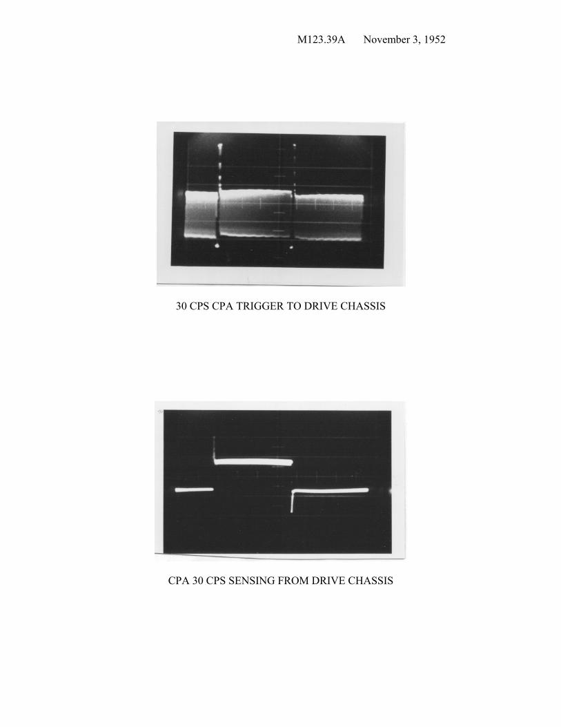
The 30 cycle square wave from the multi-mixer, horizontal flyback pulse, and integrated
vertical sync pulse were all compared for phase coincidence. As long as this coincidence
occurred a blocking oscillator was triggered at a 30 cycle rate. The sawtooth from the output of
this blocking oscillator was DC coupled to provide bias for a second blocking oscillator and the
time constants were so adjusted that failure of the first blocking oscillator to fire once in a 5
cycle interval would permit the second oscillator to fire and inject an additional pulse into the 60
cycle trigger to the multi-mixer circuit. If coincidence was achieved only once in a 5 cycle
interval, the first blocking oscillator could fire and thus continue the existing CPA phase. Hence
the possibility of noise knocking the circuit out of correct phase depends upon the probability of
having six missed coincidents in a row; the noise performance once phase locked is therefore
very good. If the circuit should get out of the correct phase the time it takes to lock in correct
phase depends upon the signal to noise ratio, requiring a longer time under poor signal to noise
conditions. This seems to be a desirable characteristic and indeed the circuit performed quite
well.
M123.39A November 3, 1952
30 CPS CPA TRIGGER TO DRIVE CHASSIS
CPA 30 CPS SENSING FROM DRIVE CHASSIS
M/l23.40 November 3, 1952
R.F., I.F. Sound And Video Section
The receiver must be able to take a standard Black and White or NTSC color RF
television signal from a 300 transmission line and produce video signal, chroma signal, audio
signal, and stripped sync for use in the other units. The band pass must be such as to eliminate
interference from channels adjacent to the one being received, and at the same time amplify
without distortion the incoming signals. It should be designed to minimize picture errors caused
by incorrect local oscillator tuning so that this adjustment is not critical.
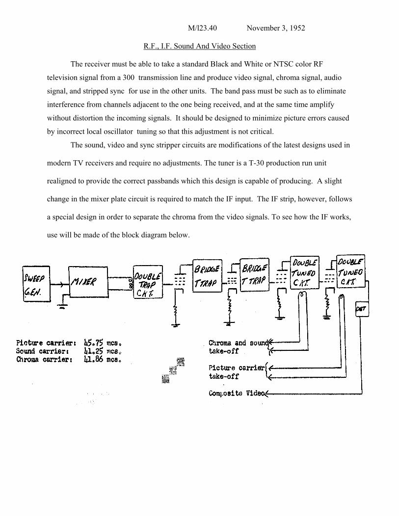
The sound, video and sync stripper circuits are modifications of the latest designs used in
modern TV receivers and require no adjustments. The tuner is a T-30 production run unit
realigned to provide the correct passbands which this design is capable of producing. A slight
change in the mixer plate circuit is required to match the IF input. The IF strip, however, follows
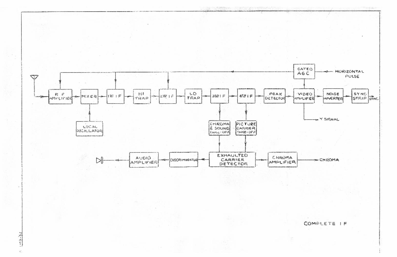
a special design in order to separate the chroma from the video signals. To see how the IF works,
use will be made of the block diagram below.
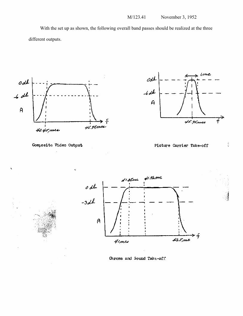
M/123.41 November 3, 1952
With the set up as shown, the following overall band passes should be realized at the three
different outputs.
M/123.42 November 3, 1952
The Video channel should have a bandwidth such that no color carrier signal will
appear at the Y signal input on the Drive Chassis, as otherwise beats may occur with the line
structure of the tube and the 7 mc writing frequency. The chroma and sound take off must not
have any Y signal present or the saturation of the color will be incorrect. Low frequency Y
signal in the sound channel may cause audio buzz if not limited off.
The Picture Carrier is separated and used in the exhaulted carrier detection of the
chroma and sound signals. This detector consists of a 6AS6 mixer which beats 41.86 mc color
carrier with 45.75 mc picture carrier to produce 45.75 - 41.66 = 3.89 mc chroma signal and
41.25 mc sound carrier with 45.75 mc picture carrier to produce a 4 1/2 mc sound which is fed to
a 6BN6 limiter-discriminator, detected, and amplified.
It must be assumed that all stages have been neutralized, properly shielded and
bypassed. Then the unit may be aligned stage by stage using conventional methods, A complete
block diagram is attached.
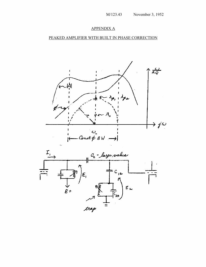
M/123.43 November 3, 1952
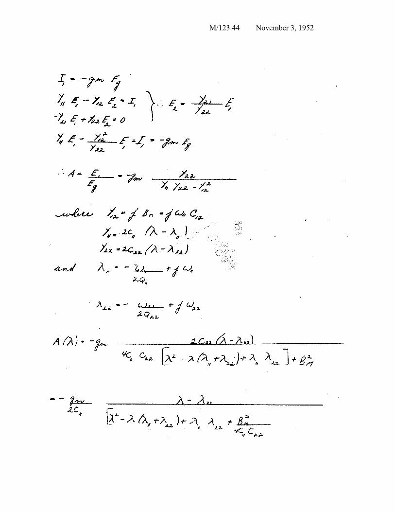
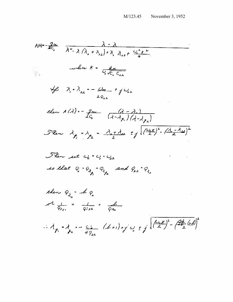
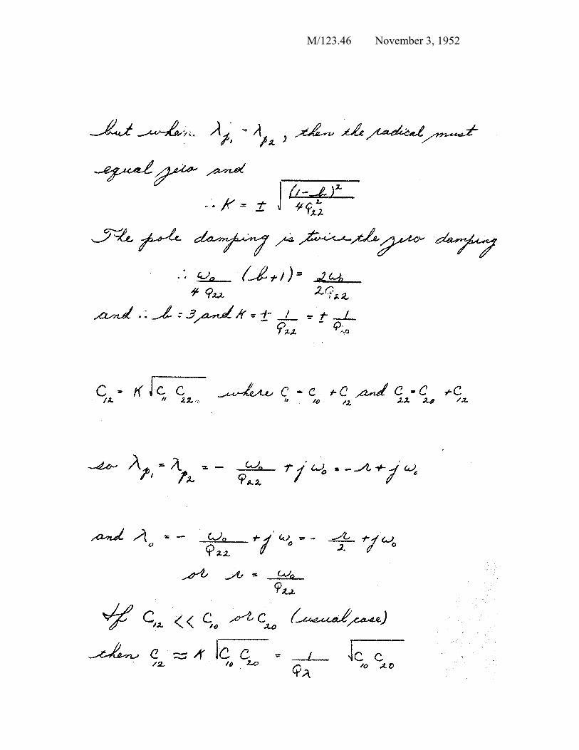
APPENDIX A
PEAKED AMPLIFIER WITH BUILT IN PHASE CORRECTION
M/123.44 November 3, 1952
M/123.45 November 3, 1952
M/123.46 November 3, 1952
M/123. 47 November 3, 1952
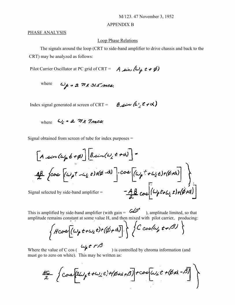
APPENDIX B PHASE ANALYSIS
Loop Phase Relations
The signals around the loop (CRT to side-band amplifier to drive chassis and back to the
CRT) may be analyzed as follows:
Pilot Carrier Oscillator at PC grid of CRT =
where
Index signal generated at screen of CRT =
where
Signal obtained from screen of tube for index purposes =
Signal selected by side-band amplifier =
This is amplified by side-band amplifier (with gain = ), amplitude limited, so that amplitude remains constant at some value H, and then mixed with pilot carrier, producing:
Where the value of C cos ( ) is controlled by chroma information (and must go to zero on white). This may be written as:
M/123. 48 November 3, 1952
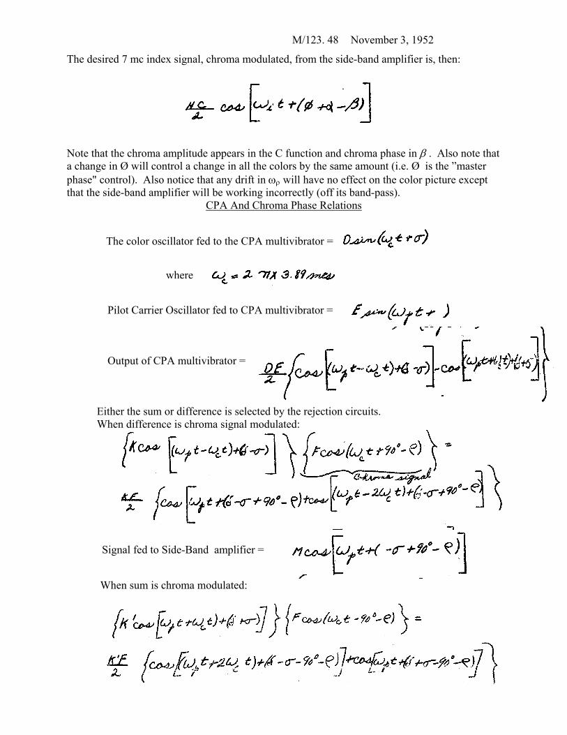
The desired 7 mc index signal, chroma modulated, from the side-band amplifier is, then:
Note that the chroma amplitude appears in the C function and chroma phase in β . Also note that a change in Ø will control a change in all the colors by the same amount (i.e. Ø is the ”master phase" control). Also notice that any drift in ωρ will have no effect on the color picture except that the side-band amplifier will be working incorrectly (off its band-pass).
CPA And Chroma Phase Relations
The color oscillator fed to the CPA multivibrator =
Pilot Carrier
Output of C
Either the sumWhen differen
Signal fed to
When sum is
where
Oscillator fed to CPA multivibrator =
PA multivibrator =
or difference is selected by the rejection circuits. ce is chroma signal modulated:
Side-Band amplifier =
chroma modulated:
M/123. 49 November 3, 1953
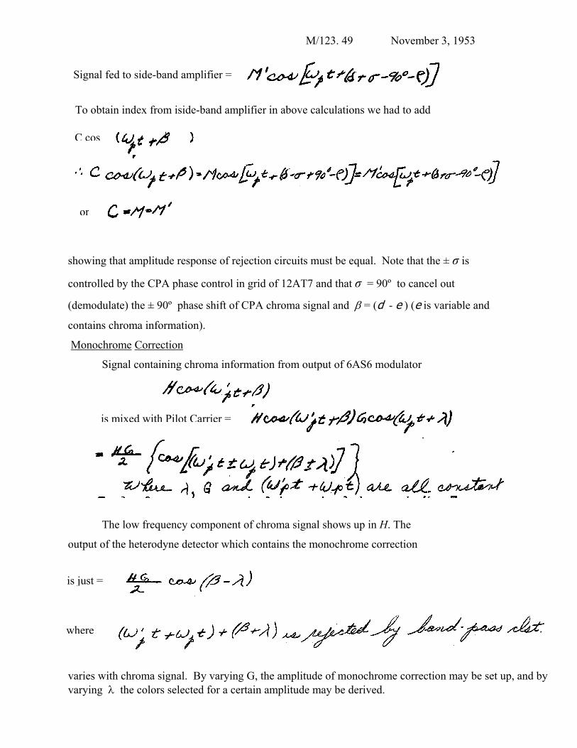
Signal fed to side-band amplifier =
To obtain index from iside-band amplifier in above calculations we had to add
sh
co
(d
co
M
o
vv
or
owing that amplitude response of rejection circuits must be equal. Note that the ± σ is
ntrolled by the CPA phase control in grid of 12AT7 and that σ = 90º to cancel out
emodulate) the ± 90º phase shift of CPA chroma signal and β = (d - e ) (e is variable and
ntains chroma information).
onochrome Correction
Signal containing chroma information from output of 6AS6 modulator
utput
e
ariesaryin
is mixed with Pilot Carrier =
The low frequency component of chroma signal shows up in Η. The
of the heterodyne detector which contains the monochrome correction
is just =wher
C cos
with chroma signal. By varying G, the amplitude of monochrome correction may be set up, and by g λ the colors selected for a certain amplitude may be derived.
M/123. 50 November 3, 1952
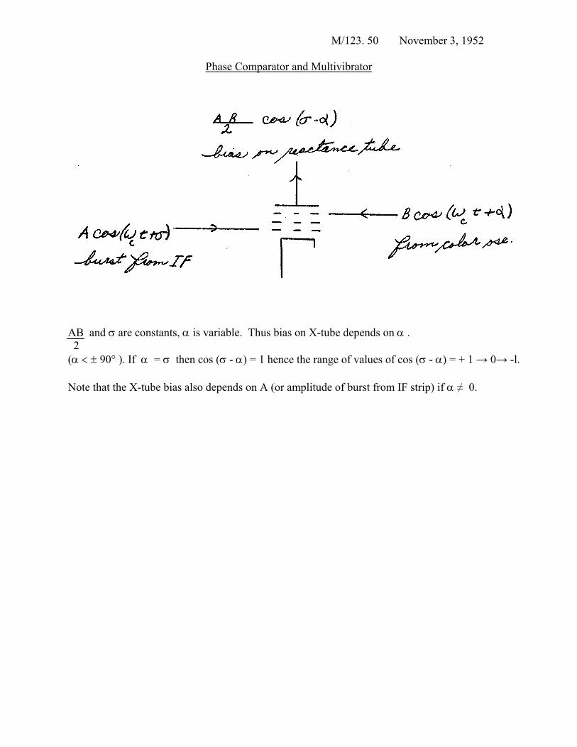
Phase Comparator and Multivibrator
AB and σ are constants, α is variable. Thus bias on X-tube depends on α . 2
(α < ± 90° ). If α = σ then cos (σ - α) = 1 hence the range of values of cos (σ - α) = + 1 → 0→ -l.
Note that the X-tube bias also depends on A (or amplitude of burst from IF strip) if α ≠ 0.
M/123.51 November 3, 1952
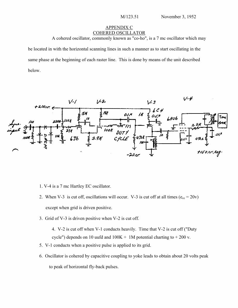
APPENDIX C COHERED OSCILLATOR
A cohered oscillator, commonly known as "co-ho", is a 7 mc oscillator which may
be located in with the horizontal scanning lines in such a manner as to start oscillating in the
same phase at the beginning of each raster line. This is done by means of the unit described
below.
1. V-4 is a 7 mc Hartley EC oscillator.
2. When V-3 is cut off, oscillations will occur. V-3 is cut off at all times (ecc = 20v)
except when grid is driven positive.
3. Grid of V-3 is driven positive when V-2 is cut off.
4. V-2 is cut off when V-1 conducts heavily. Time that V-2 is cut off ("Duty
cycle") depends on 10 uufd and 100K + 1M potential charting to + 200 v.
5. V-1 conducts when a positive pulse is applied to its grid.
6. Oscillator is cohered by capacitive coupling to yoke leads to obtain about 20 volts peak
to peak of horizontal fly-back pulses.
M/123. 52 November 3, 1952
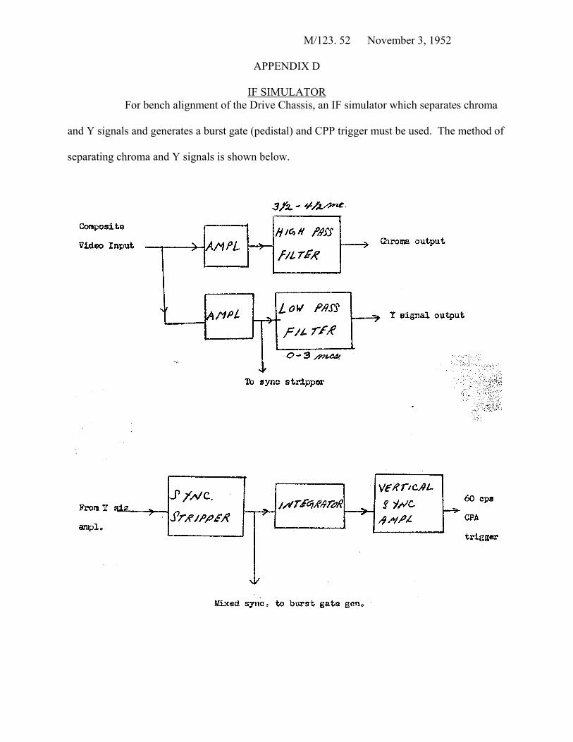
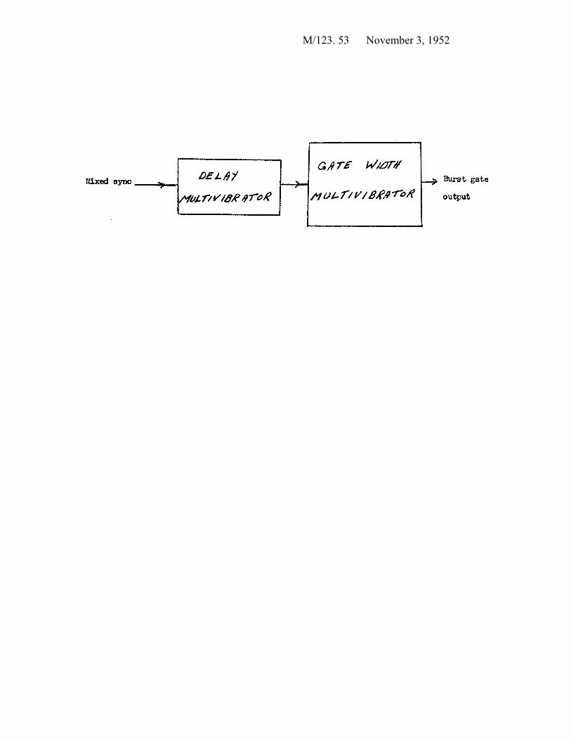
APPENDIX D
IF SIMULATOR For bench alignment of the Drive Chassis, an IF simulator which separates chroma
and Y signals and generates a burst gate (pedistal) and CPP trigger must be used. The method of
separating chroma and Y signals is shown below.
M/123. 53 November 3, 1952
M/123.54 November 3, 1952
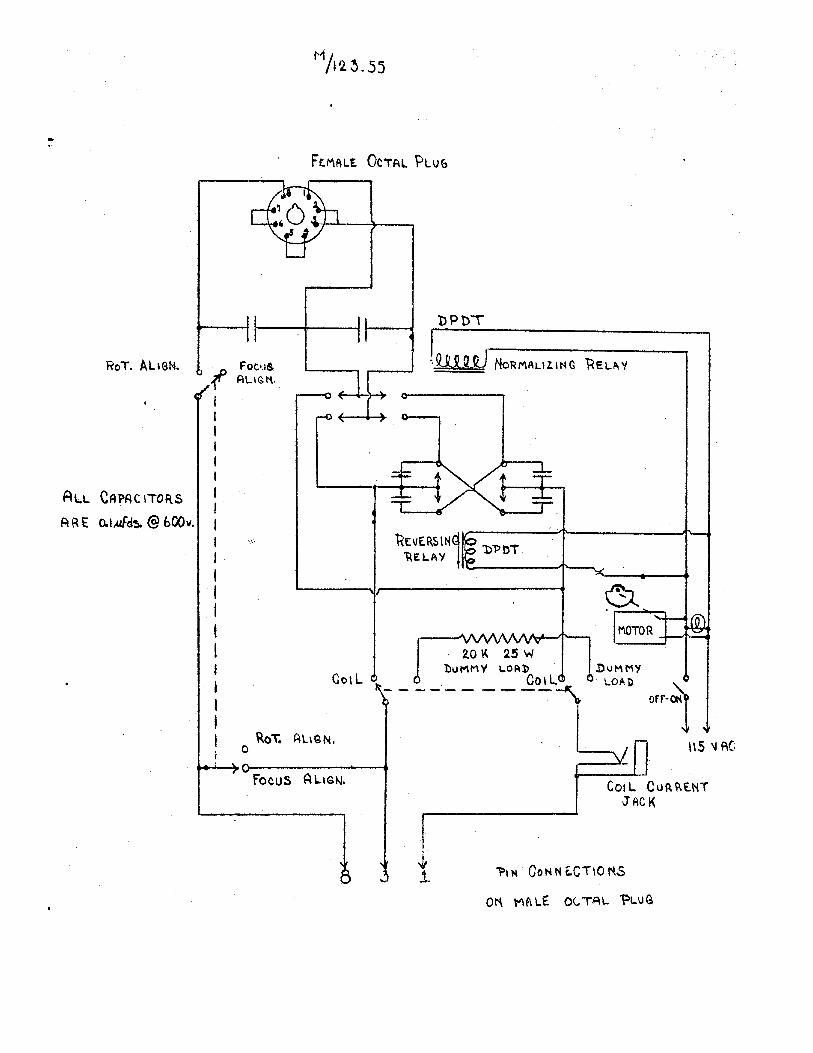
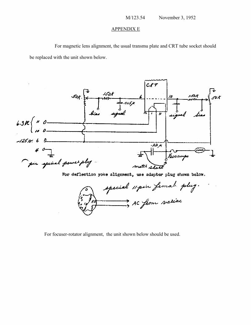
APPENDIX E
For magnetic lens alignment, the usual transmu plate and CRT tube socket should
be replaced with the unit shown below.
For focuser-rotator alignment, the unit shown below should be used.