Embed Size (px)
Citation preview

November, 1970/75 cents
Broadcast Engineering%the technical journal of the broadcast -communications industry A HOWARD W. SAMS PUBLICATION
UHFAntennaReview
page 22
RCA Video Cart Machine
Solving Color Problems
Testing Transistors

How good is the new ElectroNoice RE20studio dynamic microphone?Here's proof from the new scoringstage at Glen Glenn.
The fine reputation of Glen GlennSound Company rests on their
knowledge of sound ... their ability toturn a full symphony orchestra into aperfect sound track for TV, the movies.or a new album. And their desire to befirst with the finest.
So for their new scoring Studio M,Glen Glenn engineers asked to see thelatest products in every category ... tape,film, electronics, and - of course - mi-crophones. Especially a new E -V dynamiccardioid microphone which they had seenin prototype form earlier.
Glen Glenn put the RE20 to the test.Including days of studio experiments andactual sessions that pitted the RE20against every type of musical instrument.Plus a searching critique by the musiciansthemselves. The RE20 passed every testwith flying colors.
As a result, when Studio M was com-pleted, RE20's were on the booms ...almost four dozen of them from ourfirst production run.
Since then, Glen Glenn has scheduleda number of major recordings withRE20's. And the RE20 has often beenused where previously an expensive con-denser was the automatic choice. Why?Because the RE20 has proved itself asignificant advance in microphone design.With wide -range, peak -free response onaxis (even the off -axis response is betterthan many other studio microphones onaxis). Transient response rivals any otherstudio microphone, regardless of design.Directional control is uniform and pre-dictable from every angle. Yet proximityeffect is virtually eliminated (a problemthat plagues amost everycardioid - except E -VContinuously Variable -13'microphones).
MODEL RE20dynamic cardioid studiomiorophone $425.00 list,
less normal trade discounts.
In short, the RE20 does everything agood condenser does, and some thingsbetter. Without the complication of powersupplies. Or special cables. Or shockmounts or windscreens (they're both builtin). Or the need for equalization just toovercome design faults.
It's simple. It's flat. It's rugged. It'sclean. With a 2 -year performancewarranty unmatched in the industry (it'sspelled out completely on the spec sheet).The RE20. For the studio looking forbetter sound. Your E -V microphone spe-cialist will gladly loan your studio anRE20 to make any tests you like. Callhim today.P. S. For full technical data on the RE20, write us today.To find out more about Studio M, write Joe Kelly, VP,Engineering, Glen Glenn Sound Company, 6624 RomaineSt., Hollywood, Calif. 90038
ELECTRO-VOICE, INC., Dept. 1101V638 Cecil Street, Buchanan, Michigan 49107
A SUBSID ARY OF GULTON INDUSTRIES, INC.
Circle Number I on Reader Reply Card

STAIITATof the organization chartTHE TOPOrganization is the key word when it
comes to selecting the right television cam-era for your video origination requirements.Cohu's economical 3200 Series Self -Con-tained Television Camera has built-in versa-tility that puts it on top of a chart full ofpossible variations to meet every application.
Start at the top with the basic solid-statecamera. It's designed to meet needs fromlive to film chain requirements and be flex-ible enough to fit when your facility expands.
All video origination circuitry is mountedon quickly interchangeable plug-in boards.A flip -down rear door makes for easy main-tenance and adjustments.
You can select either standard vidicon or,for increased sensitivity and low "lag," thePlumbicono,' tube. The Plumbicon camerabecomes a superior studio unit with the addi-tion of a snap -on viewfinder, intercom head-set and zoom lens.
For film chain use, the 3200 can be speci-fied with standard vidicon and film cameracontrol.
For special applications a full line of ac-cessories can equip your camera for totalremote control capability.
A plug-in sync generator is available as anoption. Or you can select a drive generator(for use from an external sync source) toprovide common sync to multiple cameras.It's easier when you start at the top. Forcomplete details contact your nearest Cohurepresentative or the TV product line man-ager direct at 714-277-6700, Box 623,San Diego, California 92112, TWX 910-335-1244.
!Trade Mark of N. V. Philips Co.
BASIC 3200 SERIESSELF-CONTAINED
TELEVISION CAMERA
PLUMBICON EQUIPPED VIDICON EQUIPPED
LIVE LIVE REMOTE LIVE FILMSTUDIO CONTROLLED STUDIO CHAIN
CAMERA CAMERA CAMERA CAMERA
LIVE REMOTECONTROLLED
CAMERA
ELECTRONICS, INCSAN DIEGO DIVISION
November, 1970
Circle Number 4 on Reader Reply Card

November, 1970 111 Volume 12, No. 11
13roadeast EngineeringThe technical journal of the broadcast -communications industry
14101me22 Reviewing UHF Transmitting Antennas. The shorter UHF
wavelengths and small physical dimensions dictate differenttechniques in the application of antenna principles. Includesdescription of the types and operational theory, and goes intobeam tilt. Pat Finnegan.
28 The First Video Tape Cartridge System. Operational expla-nation of RCA's "first -of -a -kind" system, illustrated with pic-tures and schematics. Harry Etkin.
34 The Move Toward Bidirectional CATV. BE's CATV editordetails many of the practical possibilities for bidirectionalcommunications through CATV services. Includes severalexamples of bidirectional systems. Leo G. Sands.
38 Avoiding Lightning Damage To Power Supplies. The authorexplains that solid state devices cannot yet withstand the light-ning hits as well as vacuum tubes and tells what he did toreduce the problem. Horace N. Smith.
42 Color Balance Method For Small Market Stations. The WTMVstory of how they devised a corrective method for imbalancein the shades and tints of color film, slides and cameras. PhilDean.
44 Testing Transistors. The second articles in a series describingmethods of checking transistors. In this part BE's technicaleditor covers the Beta test and gives schematic for circuitthat will give turn-off, turn -on, and ohmmeter tests withoutmoving ohmmeter or transistor clip leads. Carl Babcoke.
ABOUT THE COVER
Several antenna manufac-turers are now testing tele-vision antennas at outdoortest sites before delivery.This site shows an Ampexantenna under test. For areview of UHF antennas,see article on page 22.(Photo courtesy of Ampex)
DEPARTMENTS
Direct Current 4
Letters to the Editor .. 8
Industry News 12
Educational Broadcasting 18New Products 48Book Reviews 57Tech Data 58Ad Index 62Classified Ads 64
Copyright, 1970, Howard W. Sams & Co.. Inc. All Rights Reserved: Material may not be reproduced or photocopied in any form without written permission of publisher.
EDITORIAL
GEO. H. SEFEROVICH, DirectorRONALD N. MERRELL, EditorCARL BABCOKE, Solid State
MORRIS COURTRIGHT, AutomationPAT FINNEGAN, MaintenanceHOWARD T. HEAD, FCC RulesROBERT A. JONES, Facilities
WALTER JUNG, Education/Closed CircuitANDRA PETERSON, Editorial Assistant
H. G. ROESLER, CartoonistDUDLEY ROSE, Art Director
EDITORIAL ADVISORY BOARD
LES NELSON, ChairmanHoward W. Sams & Co., Indianapolis
CIRCULATION
EVELYN ROGERS, Manager
ADVERTISING
E. P. LANGAN, DirectorR. JACK HANCOCK, Manager
S. F. WILSON, ProductionJAKE STOCKWELL, Sales
REGIONAL ADVERTISING SALES OFFICES
Indianapolis, Indiana 46206ROY HENRY
HOWARD W. SAMS & CO., INC.2469 E. 98th St.
Tele: 317/846.7026
New York, New York 10019CHARLES C. HORNER
3 W. 75th St.Tele: 212/688-6350
Los Angeles, CaliforniaJOHN D. GILLIES
3600 Wilshire Blvd., Suite 1510Los Angeles, California 90005
Tele: 213/383-1552
London W. C. 2, EnglandJOHN ASHCRAFT & CO.
12 Bear StreetLeicester SquareTele: 930.0525
Amsterdam C, HollandJOHN ASHCRAFT & CO.W.J.M. Sanders, Mgr.
for Benelux & GermanyHerengracht 365Tele: 020-240908
Tokyo, JapanINTERNATIONAL MEDIA
REPRESENTATIVES, LTD.1. Shiba-Kotohiracho, Minato-ku
Tele: 502-0656
AABP -44110110- lEIPA
BROADCAST ENGINEERING is publishedmonthly by Intertec Publishing Corp., 1014Wyandotte Street, Kansas City, Missouri64105. Telephone: 913/888-4664.
BROADCAST ENGINEERING is mailed freeto qualified persons engaged in commer-cial and educational radio and televisionbroadcasting. Non -qualified subscriptions inthe U.S. are $6.00 one year, $10.00 twoyears, $13.00 three years. Outside the USAadd $1.00 per year to cover postage.Single copy rate 75 cents. Back issue rate$1.00. Adjustments necessitated by sub-scription termination at single copy rate.
Controlled Circulation postage paid at In-dianapolis. Indiana.
Robert E. Hertel, Publisher
Intertec Publishing Corp.Subsidiary of Howard W. Sams & Co., Inc.
BROADCAST ENGINEERING
CUSTOMSYSTEMSGVG CURRENTLY OFFERSTEN BASIC SWITCHINGSYSTEM CONFIGURATIONS.IN MOST CASES, WE CANSATISFY CUSTOMER RE-QUIREMENTS WITH ONE OFOUR STANDARD MODELSTOGETHER WITH OPTION-AL ITEMS WHICH HAVE BEENINITIALLY DESIGNED INTOTHE SYSTEMS.
SHOULD YOUR NEEDS DIC-TATE A CUSTOM DESIGNOR A MODIFICATION OFA STANDARD MODEL, GVGHAS A STAFF OF EXPER-IENCED SYSTEMS ENGIN-EERS WHO WILL WORKWITH YOU TO PROVIDE ASYSTEM THAT MEETS YOURREQUI REMENTS.
GVG NOW HAS OVER 100SWITCHING SYSTEMS INSERVICE. A USER LIST ISAVAILABLE ON REQUEST.
LA:21;70ia CLIL/LA.JI QL:1=Z:0 IGIQULLA ca
QL2L.:=2 QUI..7=11 /QQQ=11 X71/../1.7./=.11
QL.A.I=11 QUI.W =2:1LOU
01:20001 il:2=1=2 Q=X2L2 tOUriiii=21:21:2=X2 QQ=2.21 =2=Z:A1;Xi/Q=.2 LX.X2=2 r..12:2=2)
off:,
Ae
01'
111.11=-10104111.
0 0 Maas1111=01116, u.cto=1
ItiauQua 1-0 tu
tLJGJI;21:11:21 L-1-4-1C.X.11 L.ULJQQ1 ILAJULIL2 1=10;2, IQL1 )/b.ti..1GLW IZAAJL1 Utal l3
THE GRASS VALLEY GROUP, INCFOR ADDITIONAL INFORMATION, CONTACT GRAVCO SALES, INC.
6515 Sunset Blvd. Station Plaza East 1312 West Northwest Highway 2626 Mockingbird Lane 1644 Tullie Circle, N.E.LOS ANGELES, CALIF. GREAT NECK, N.Y. ARLINGTON HEIGHTS, IJLL. DALLAS, TEXAS ATLANTA, GEORGIA(213) 462-6618 (516) 487-1311 (312) 394-1344 (214) 352-2475 (404) 634-0521
Circle Number 5 on Reader Reply Card
November, 1970 3
DIRECT CURRENTFROM D. C.November, 1970
By Howard T. Head
Mexican Treaty Ratified, New AM Rules in Effect
The Mexican Senate has ratified the new treaty with the United Statesgoverning AM radio operation in the two countries. The treaty had alreadybeen ratified by the United States. With the exchange of the ratificationdocuments in Washington on October 15, the Commission has issued new rulesputting the provisions of the treaty into immediate effect.
The new Commission rules provide, among other things, for the presunriseoperation of more than 200 daytime -only stations operating on theMexican clear channels, and for daytime power increases to 1 kW forClass IV stations on local channels operating near the Mexican border. Sta-tions of these classes wishing to take advantage of the new provisions mustfile applications with the Commission supplying technical details.
In the case of daytime -only stations wishing to operate prior tosunrise, a letter requesting presunrise service authorization (PSA)is required. This letter must be accompanied by an engineeringshowing. Class IV stations wishing to increase daytime power arerequired to file a formal application on FCC Form 301. Completetechnical details must be furnished in response to the requirementsof the application form.
White House to Assume Greater Role in Telecommunications
The White House has established a new Office of TelecommunicationsPolicy (OTP). Named Director of the new Office is Dr. Clay T. Whitehead,Presidental Adviser, whose recommendations led to the establishmentof the new Office. Although the OTP will not have direct control overbroadcast or other matters within FCC jurisdiction, Dr. Whitehead hasmade it plain that neither he nor the President will hesitate to maketheir views known to the FCC on policy matters such as frequency al-locations, satellite communications, and cable television policy.
The Presidential order establishing the new Office provides that OTPwill place "primary" reliance on the Department of Commerce for technicaladvice. The group principally responsible for the provision of suchadvice will be the former Institute for Telecommunications Sciences(ITS) headquartered at Boulder, Colorado.
Veteran broadcast observers will recall that this group, formerlypart of the National Bureau of Standards and known as the CentralPropagation Radio Laboratory (CRPL), has been engaged in a long-standing dispute with the FCC regarding such matters as broadcast
4
(Continued on page 6)
BROADCAST ENGINEERING

Look what our customers sayabout "easy -to -operate" Gates
audio consoles ...
"With a flip of a switch, we muteloudspeakers in microseconds.And our Gatesway II never givesus feedbacks."
Earl Greer, Radio Station KXRXThe San Jose Broadcasting Co.San Jose, California
"The tri-color, illuminated selector key on ourStereo Statesman lets us see at a glance whether we're on`audition', 'program' or `off'."
John Struckell, Vice Pres. & Gen. Mgr.Radio Station WFPGEastern Broadcasting Co.Atlantic City, N.J.
"Our Gates Dualux II savesus time and steps. We controlFM and stereo from oneconvenient location with ease."
George W. Watson, Chief EngineerRadio Station WDRC & WDRC-FM, Buckley Broadcasting Corp. of ConnecticutHartford, Connecticut
"Our Gates Yard II gives us unbelievably high performance with minimum work."Gene Showalter, ManagerRadio Station WDQNDuQuoin Broadcasting Co.DuQuoin, Illinois
For the finest in 100% transistorized audio consoles . . . look and listen to Gates.Or ask our customers! For more information about "easy -to -operate" audio consoles,write today. Gates, 123 Hampshire Street, Quincy, Illinois 62301.
GATESA DIVISION OF HARRIS-INTERTYPE
Circle Nember 6 on Reader Reply Card
November, 1970 5

(Continued from page 4)
channel allocations, land mobile operation, and even such topics asthe sale of frequency spectrum to the highest bidder. Considering thebackground of the new Office, broadcasters and other licensees under FCCjurisdiction can expect an interesting future, to say the least.
New FM Interference Group Being Formed
The Commission, at the request of a major television trade association,is organizing a new Advisory Committee to study the problem of FMinterference to television reception. The committee will include engineersfrom the FM broadcast industry, the television broadcast industry, andthe receiver manufacturing industry, as well as from the FCC.
The Commission has been receiving an increasing number of complaintsfrom the public in recent years of interference to television receptionfrom FM and other sources. The number and seriousness of these complaintsare on the increase, not only because of the growth of FM broadcasting,but also because of the much greater sensitivity of color televisiontransmissions to interfering signals. So many complaints are beingreceived (25,000 to 30,000 per year) that the Commission is no longer ableto respond to individual cases except with general guidelines.
Color TV Improvement Under Continued Study
The Joint Committe for Intersociety Coordination (JCIC), studyingsources of degradation in color television pictures, has issued areport of its findings from tests in Chicago area. These tests coveredthe portion of the television transmission system from the studio outputterminals to the receiver input terminals.
These tests showed this portion of the television system to be an im-portant source of color signal degradation. Measurements were made ofburst-to-chroma phase shift, chrominance-luminance ratio, differentialgain and phase, chroma-to-burst amplitude ratio, color burst effects,and multipath effects. In each case, significant transmission errorswere found. One disturbing conclusion is that in many instances systemsoperating within FCC signal tolerances were still incapable of producingsatisfactory color pictures.
Signal observations were made at several test points ranging from thestudio output through the transmitter input and output to the receiverinput terminals. Phase and amplitude errors occured in all portionsof the transmission system, with a disturbingly high proportion apparentlyassociated with the propagation path between transmitter and receiver.
Meantime, reports are accumulating of experience with the verticalinterval reference signal (VIR) devised by the Broadcast TransmissionsSystem Committee (BTS) of EIA, currently being tested by the threemajor television networks (See June, 1970 D.C.).
6 BROADCAST ENGINEERINGCircle Number 7 on Reader Reply Card

There is our foam dielectric coax witha new copper corrugated outer conduc-tor. We call it Cuflex.' The same cablein aluminum sheathing is famous Foam -flex. Spirafil II is our aluminum sheathedair dielectric cable. With a corrugatedcopper outer conductor it answers to thename Cutil." We have connectors tomatch all four.
In coaxial cable, whatever your needs,we probably have it. In stock, in all popu-lar sizes, in warehouses across the country.
Let us tell you more. Write tocicn fordetails: Phelps Dodge CommunicationsCompany, 60 Dodge AphielpsAvenue,North Haven,Connecticut 06473_ dodge
COMUM.COVOIN Gompauy
lil

AffitOMed a
litea,k `Am //
RUMBLE?
NOT WITH THE
QRK is now producing turn-tables with rumble figuresfar better than NAB specifi-cations!!
QRK rumble, -39db NAB, -35db
QRK weighted umble -62db
Instant start; reliable; une-qualled service; attractivelypriced; and now . .. rumblefree performance!!
deg ELECTRONICPRODUCTS, INC.
1568 NORTH SIERRA VISTA, FRESNO,CALIFORNIA 93703 Phone: 209 251-4213
Subsidiary ofCCA ELECTRONICS CORP.716 JERSEY AVENUE. GLOUCESTER CITY,NEW JERSEY 08030 Phone. 609 456-1716
LETTERS
How MuchDear Editor:
It's good to see the industry stillhas Chief Engineers like Mr. Snyderat WJOY in South Burlington,Vermont. After some fifteen yearsbroadcasting, I have seen manyradios stations. Those that wereclean and neat stayed on the airand sounded like a broadcastingstation. These stations, for the mostpart, had a fulltime Chief Engineer,not a 90 -day -wonder or a managerturned engineer, or a contract engi-neer, but someone who took pridein being able to see his face in thefront glass of the transmitter.
Where have these great radiobroadcast people gone? Television,naturally, took its share and manyothers entered into industry. Why?Simply because many station own-ers were not able or refused to paythe price a professional person wasentitled to receive. Now, we arepaying the price; we have an in-dustry that lacks enough truly quali-fied engineers and is flooded withbums who have nothing more thana blue piece of paper.
Let's not do away with the legiti-mate engineers, let's do get rid ofthe phonies in the business. Let'spay our engineers what we pay ourannouncers and program directors.
The only product a station hasto sell is sound; pay your engineera decent salary and he can worrymore about making your stationsound better instead of how he'sgoing to make ends meet at theend of the month.
As someone who came up throughthe ranks from sweeping the floorin my father's station to a quarterownership of my own station, I be-lieve a good engineer is worth moreto you than anyone else in yourstation.
Treat your engineer like a pro-fessional or he's liable to join themass exodus from broadcasting.
William K. HoisingtonStation ManagerWKYV-FMVicksburg, Miss.
El
How Soon?Editor's Note: When we start dis-
cussing the economics of broadcast-ing, we run into heavy traffic. Butone thing is for certain: far toomany engineers never heard of a40 -hour week. (Doctors are askingnow, what is a house call?) Whentrouble comes, does a day ever end?
The engineer can and will movearound . . . . as a reaction thechanging technology and the growthof related industries. And he soonwill be forced to make more movesbased on salary increases.
As far as dropping from AM andFM is concerned, the irony of itall is that they will return . . . moreoften than you think . . . as factoryreps or contract engineers. In theend, there is no way to avoid pay-ing for engineering excellence.
Prices Wanted OnProduct LiteratureDear Editor:
On many occasions I mail inyour "Reader Service Card" re-questing information on items of in-terest to me. For this service I amvery much thankful. However, Ihave one gripe about which I havebeen meaning to write to you forsome time. This is not against yourfine magazine, but to the manufac-turers of the products for which Iask for information.
(Continued on page 10)
7N/NK arinNom4,- We'll- fat Th't ffit.57-,5E7 Poor "/
Circle Number 44 on Reader Reply Card
8 BROADCAST ENGINEERING
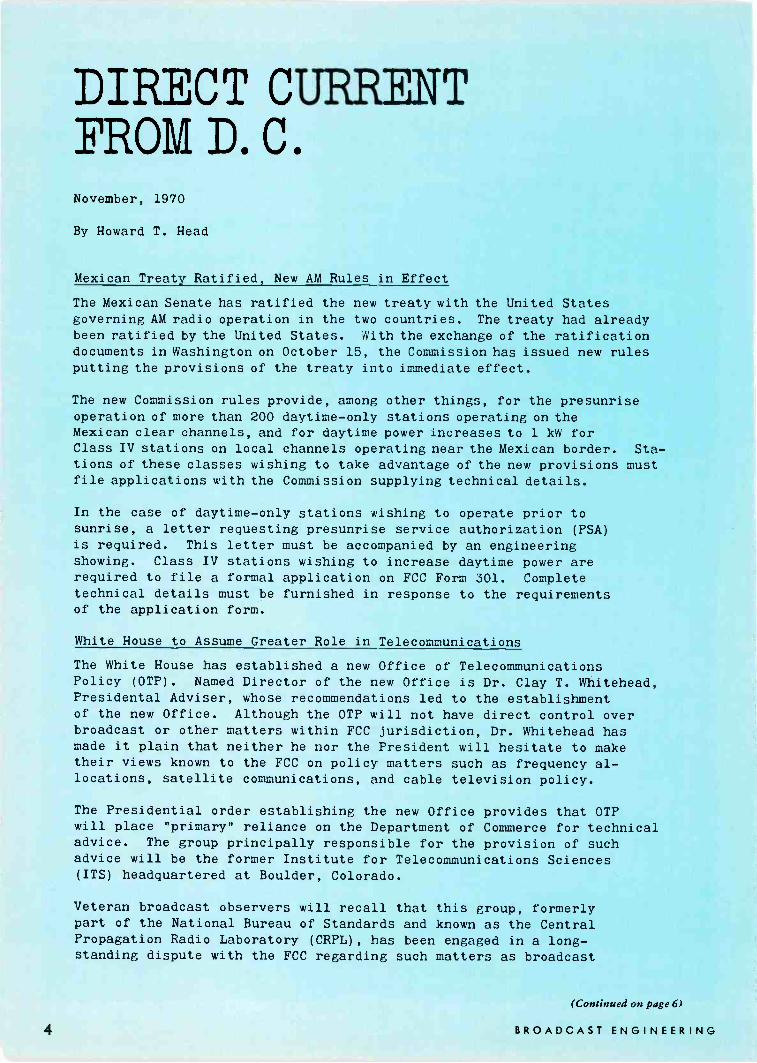
IN MAKING RECORDSSTANTON IS THE STANDARD
Whatever your requirements for recording andplayback, Stanton's Series 681 cartridges arethe calibration standard. And there is a 681 modelengineered specifically for each of these criticalapplications.
The Stanton 681A-For Cutting Head CalibrationWith Stanton's Model 681A, cutting heads can be
accurately calibrated with the cartridge,for it hasbeen primarily designed as a calibration standard inrecording system checkouts for linearity andequalization. Frequency response is factory cali-brated to the most rigid tolerances and the flattestpossible response is assured for precise alignmentof recording channels. Implicit in this kind ofstability and constancy is a reliability factor un-matched by any other cartridge for this application.
The Stanton 681EE-For Critical ListeningIn critical playback auditioning, whether a
pre -production disc sample sounds too "dead" or"bright" is largely a matter of cartridge selection.Here too, Stanton provides the evaluation standardin its model 681EE. In this application, the Stanton681EE offers the highest obtainable audio quality in
Circle Number 8 on Reader Reply Card
Photographed at Capitol Records.
the present state of the art. It is designed for Icw-distortion tracking with minimum stylus force.regardless of the recorded velocity or the distance ofthe groove from the disc center. High compliance,low mass and low pressure assure perfect safetyeven on irreplaceable records.
All Stanton Calibration Standard cartridges areguaranteed to meet the specifications with exactinglimits. Their warranty comes packed with each unit-the calibration test results for that individualcartridge.
For complete information and specifications writeStanton Magnetics, Inc., Terminal Drive,Plainview, L.I., New York.
sTaNTon
November, 1970 9
P
(Continued from page 8)
The gripe is this. Why don't theadvertisers of the products forwhich information is requested, sendalong the PRICE or PRICES ofthe items?
There is nothing that gripes memore than to have to take time outto write a second time to get a
price of some product that I maybe interested in buying.
Antonio VaccaroChief EngineerRadio Stations WHEB/WPFMPortsmouth, N.H.
Tower Painting ErrorA few gremlins crept into the
act in the September issue of BE.In the "Outside Maintenance"article on page 39, second column,line seven, the sentence should read:The TV antenna must have a 6MHz bandpass, so there is roomfor standing waves to appear in thesideband area that will not neces-sarily show up on the VSWR indi-cators.
Also, Figure 4 on page 41 thereis a tower painting problem. Thetower is a radio tower and should
TOTAL CAPABILITY=FAIRCHILD
INTEGRA II SYSTEM!
r11:11:1-WiI11.1
Capability No. 1: Easily integrated audiocomponents.
Capability No. 2: Simple and efficientconstruction.
Capability No. 3: Practically any complexaudio system can be designed.
Capability No. 4: Remote control of audiofunctions (optional).
Capability No. 5: Solid-state technologyprovides compact, efficient, convenientand economical audio control.
Capability No.6: Unmatched conveniencein maintenance.
Capability No. 7: Advanced light -con-trolled technology.
Capability No. 8: Complete freedom fromcontact noise, distortion, frequency dis-crimination and mechanical problems.
Capability No.free perfect sw
Capability No.of componentassure highest
Capability No.cessories.
9: Noise -free and bounce -itching.
10: Space-age standardsdesign and manufacturereliability.
11: Complete line of ac -
Capability No. 12: Compatible with yourexisting equipment.
For complete details and new colorfulIntegra II brochure write to:
FAIRCHILDSound Equipment Corp.Dept. BE -I I 10-40 45th AvenueLong Island City, N.Y. 11101
not have included a TV antenna.The total tower height is 210 feet.As it is shown in the drawing, thecolor bands would be wrong. Thetop and bottom bands must beorange. Eliminate the TV antennaand show the tower height as 210feet and it will be correct.
ORANGE -0-
30'
30'
7 BANDS
14 ORANGE)
(3 WHITE)
ORANGE-p.
In line with tower painting, thereader should be aware of the factthat the Commission has proposeda change in the width of the colorbands. The proposed rule wouldmake the maximum width 100 feetinstead of 40 feet.
Screen ExamineesWith InterviewDear Editor:
I would like to add my idea tothe present controversy concerningthe licensing of broadcast engineersand the relaxing of the "FirstPhone" rules.
The possession of a "First Phone"license in itself seems to mean noth-ing except the holder is able toretain a certain amount of informa-tion long enough to set down andanswer a group of questions. Thisdoes not mean that he even under-stands the questions, let alone theanswers. In my experience as aChief Engineer, I find that most"Third Phone" holders know asmuch about a transmitter as a "FirstPhone" holder who received itthrough a fast memory course. Inthe light of that statement, it seemsthe relaxing of the rules to permit"Third Phone" holders the right oftransmitter watches on directionalantenna and higher powered trans-mitters means little one way or theother, technically.
In fact, I know of broadcasters
I0Circle Number 9 on Reader Reply Card
BROADCAST ENGINEERING

who are using announcers who hurtthe 'sound' of the station simply be-cause they have a "First" and arethe only ones available to operatesince the station feels they cannotafford an announcer and engineerboth at the same time for manyshifts.
It seems a practical solution forthe FCC to find out who can main-tain a radio station, would be inaddition to answering the "FirstPhone" questions, an engineer mustalso have an interview with a FCCinspector who knows radio and ra-dio stations. It certainly doesn't takeme but a few minutes to find outif a prospective engineer knows en-gineering. A few questions aboutequipment, transmitters, transmis-sion lines, impedance matching,consoles, phone lines, etc. wouldcertainly let an inspector know ifthe applicant was familiar with ra-dio broadcasting and could be re-sponsible for the maintenance andrepair of a transmitter and antennasystem. I would welcome such aninterview with an inspector in orderto have an indorsement on mylicense which means that I couldbe employed for the maintenance ofradio station equipment. It wouldseem to be better to up grade thelicenses of those qualified ratherthan merely relaxing the rules toallow a lower grade of operator tobe on duty at a station.
I'm sure the FCC inspectorswould not like the extra time forinterviews, however, if such achange is made so that the "FirstPhone" license is not needed theywould certainly have more time tointerview prospective Chief Engi-neers, since the long lines of "First"Class license applicants would beeliminated.
Horace N. SmithCE for WERK andWCTW AM/FM
Buying? Selling?
Get ResultsWith Classified Ads
In
Broadcast Engineering
Everythingbut the cameraand the monitor.
Aqua CCTVRemote ControlPan/Tilt UnitsNow you can get all the components ycu need for an efficientand reliable closed circuit TV system. From one source. Includ-ing power supplies, camera housings, mounting hardware,joy -stick controls and other accessories. For all kinds ofenvironmental conditions . . . indoor, outdoor, high and lowtemperatures, underwater, explosion proof.
These superior CCTV products are now being manufacturedby Cunningham Corporation . . . for over 16 years a leader inthe manufacture of audio -video switching devices. Every com-ponent meets our strict requirements for design excellence,quality, and built-in reliability. And you'll find our deliveries tobe fast and dependable.
Send for your free copy of the Cunningham/Aqua CCTVCatalog. One look will show you what we mean when we say"everything but the camera and the monitor." And we're work-ing on that, too.
Cunningham Corporation, 10 Carriage Street, Honeoye Falls,New York 14472. Phone (716)-624-2000.
CunninghamCorporationSUBSIDIARY OF GLEASON WORKS
November, 1970
Circle Number 10 on Reader Reply Card

'MP
COMPARE...
YOU'LL BUY
a CCA
FM Transmitter
CCA is the only major FM equip-ment supplier who uses modernzero bias triodes in a groundedgrid configuration. We've onlylost three tubes in over 100 instal-lations and some of these tubesare in operation after 20,000hours. CCA tube cost is almostnegligible. CCA FM Transmit-ters don't require neutralization.They're superstable and ex-tremely reliable. They are veryefficient and draw less power
from the line than anycompetitive transmitter.Compare - you'll agreewith your fellow broad-casters. CCA FM trans-mitters cost less to buy,less to operate, are un-surpassed for reliability.
11111,mmema
Bit
CCA
CCA Electronics Corp.716 Jersey Avenue
Gloucester City, N. J. 08030Telephone: (609) 456-1716
NEWSBoosters, Too
Approval For FM TranslatorsUse of FM boosters and trans-
lators by FCC stations has beenauthorized by the Commission inan amendment to Part 74 of therules (Docket 17159). Establishmentof low power translator and boosterstations will help extend FM radioservice to areas receiving poor ser-vice because of distance or uneventerrain. Translators are in regularuse to extend TV coverage, but inthe past, FM translators have beenauthorized only on an experimentalbasis (Translators retransmit anoriginating station's signal on a dif-ferent frequency. Boosters are re-peating devices that amplify andretransmit a signal on the samechannel as the originating station.)
The rules allow FM boosters withtransmitter power output of up to10 watts nationwide and FM trans-lators with transmitter power out-put of up to 10 watts west of theMississippi River except for ZoneI -A. East of the Mississippi Riverand in Zone I -A, power will belimited to one watt.
The new rules provide that com-mercial FM translators will be au-thorized only on Class A small com-
munity, channels designated in theCommission rules. Noncommercialeducational FM translators will beauthorized on the 20 FM channels,(201 through 220, 88.1 MHzthrough 91.9 MHz) reserved fornoncommercial educational use. FMtranslators will not be permitted torebroadcast commercial FM sta-tions on channels reserved for non-commercial educational use.
FM translators or boosters willnot be authorized within 20 miles ofthe Canadian border without per-mission from the Canadian govern-ment and, until an agreement canbe reached with the Mexican gov-ernment, no translators or boosterswill be permitted that will serve anarea within 200 miles of the Mex-ican border.
Except when specifically indi-cated in the rules, the same ruleswill apply to FM boosters as toFM translators.
FM translators, like televisiontranslators, will be authorized ona no -interference basis. FM trans-lators will be required to protecttelevision translator stations againstinterference.
Burch Wants Diversity By CompetitionFCC Chairman Dean Burch,
speaking at the 66th Annual Meet-ing of the American PoliticalScience Association in Los Angelessaid that the task of the FCCis to keep broadcasting an "open"medium of expression, to supply theframework within which the indus-try can-and must-present a di-verse fare of information and viewson significant public issues." Hesaid the Commission's primary chal-lenge was the encouragement anddevelopment of "structural diversitythrough new and competing modesof expression."
The Commission has sought toprovide for diversity of expression
for many years, Chairman Burchstated. It has worked to preventconcentration of control through itsmultiple ownership rules. Hepointed to the Fairness Doctrine,which requires presentations of con-trasting views on controversial is-sues of public importance, as insur-ing that a station will not becomea one-sided platform. He stressed,however, that it is now most im-portant to concentrate on newmodes of expression to promotediversity-media with a differenteconomic base than broadcasting aswe now know it-with the cap-ability of responding to specializedaudiences.
Circle Number II on Reader Reply Card
12 BROADCAST ENGINEERING
"in" lea rWant to know about the latest in sophisticatedterminal equipment?Talk to TeleMation!
Or talk to any of literally thousands of smartsatisfied users of TeleMation products whoknow our equipment has achieved a standardof excellence in quality, flexibility andreliability that others are hard-pressed to meet.
_as44
0,
* 4 ....... 4 a
TeleMation's TMV-551 Video DistributionAmplifier provides four completely isolatedoutputs from one bridging input. Built-inpower supply and connector panel, IC seriesregulator for constant power supp[y voltagestandard. Top color performance.
The TSG-3000 Broadcast Color Synchro-nizing Generator with all -digital circuitry, thehighest time base stability and lowest pulsejitter performance available. Plus program-mable pulse widths and digital genlock forCrashlock (next -field, operator -controlledlockup) or Ratelock (adds or subtracts oneline per field until lockup is achieved).
For the finest in gear,TALK TO TELEMATION.
BROADCAST SALES
3941 East BayshorePalo Alto, Calif. 94303(415) 969-9260
50 East 42nd StreetSuite 2301New York, N.Y. 10017(212) 687-0370
BRANCH OFFICES: ALBUQUERQUE ATLANTA BOSTON CHICAGO DALLAS DENVER :HOUSTON INDI 4NAPOLIS LAS VEGAS LITTLE ROCK NEW YORKNORWALK MILWAUKEE PALO ALTO PASADENA PHOENIX SAN DIEGO SALT LAKE CITY ST. LOUIS TULSA WASHINGTON RIO DE JANEIRO. SAO PAULO
Circle Number 12 on Reader Reply Card
November, 1970 13
Industry News(Continued from page 12)
Chairman Burch cited subscrip-tion television, CATV with itsmulti -channel capacity and its po-tential for specialized services andprograming, and educational televi-sion and its ability to offer pro-grams not dependent upon adver-tiser support, as examples of thepotential for diversity. He addedthat fuller use of UHF televisionwould provide additional oppor-tunities for public service.
Chairman Burch, noting that sat-ellites would also offer opportuni-ties in the near future, stressed thatit was the job of the FCC to pro-mote such developments, to givethe public greater access to thewidest range of information. Byconcentrating on this area, he con-cluded, the Commission can bestcarry out its mandate to give thepublic the resources it needs to doits own thinking and make its owndecisions.
See Page 34For CATV
Bidirectional Patterns
Schools Computerize Net
College students and instructorsin Texas are attending distantclasses and solving problems on aremote computer without ever leav-ing their own campuses.
The long-distance instructionaland problem -solving capabilitiesare made possible by a pioneeringnew microwave network that spans4,000 square miles and serves sev-eral Texas colleges and universities.
The network, operated by TA-GER (The Association for Gradu-ate Education and Research) en-ables these institutions to pool theirinstructional capabilities and scien-tific resources through closed cir-cuit television and a central IBMcomputing facility linked to severalremote campuses by microwave.
"With closed circuit television,scientists, engineers and college stu-dents can 'attend' graduate classesduring the normal workday withoutever leaving their plants or cam-puses," said Don Simons, the as -
Fastest thingfor tape.
"Rapid -Q"cartridge tape equipmentBetter than 100% faster cueing.Automatically. For all the details on thequick, cool, quiet, slim one,write Visual Electronics Corporation,356 West 40th Street, New York, N.Y. 10018.
sociation's academic coordinator."Students and faculty members alsocan jointly work on problems usinga single IBM computer."
The computing center is at theUniversity of Texas at Dallas andis being used by Texas ChristianUniversity in Fort Worth and AustinCollege in Sherman. Texas Chris-tian University has its own IBMsystem but can communicate withthe larger computer in Dallas forincreased problem -solving capacity.Other institutions in the networkare able to add typewriter -like ter-minals as needed and connect withthe central IBM system by micro-wave.
TAGER network participantsalso include Southern MethodistUniversity, whose own computer fa-cilities are accessible through thesystem; Bishop College in Dallas;the University of Dallas; Universityof Texas Southwestern MedicalSchool at Dallas; and Texas Wes-leyan College in Fort Worth.
Circuits are also available at theUniversity of Texas at Arlington forfuture expansion of both the teach-ing and computer capabilities.
Closed circuit television and high-speed computer data transmissionbetween campuses can be operatedsimultaneously on a single micro-wave band.
Dialogue exchange, consideredvital in an educational process, ispreserved through two-way voicecommunication built into the net-work. A student at a distant cam-pus or plant taking a televisedcourse can see the instructor andvisual aids and also can pose ques-tions during the lecture. All stu-dents can hear the questions andresponses.
Through a technique known astime-sharing, several persons at thecampuses served by the computercan solve problems simultaneouslyon the IBM System/360 Model 50on the UT Dallas campus.
"This network once was just agrand idea, as it still is throughoutmost of the country. But we aban-doned our individual campus tiesand jointly turned the idea into avaluable and functioning system,"
Circle Number 13 on Reader Reply Card
I4 BROADCAST ENGINEERING

said Simons. "We're still expand-ing and developing the network,which represents an investment ofmore than $1.5 million, and ex-ploring other educational potentialsit offers."
"The computer jumps from oneproblem to another and back again,but the speed is so great that eachindividual user has the impressionthat the computer is working solelyfor him," said John Carpenter, di-rector of the IBM Center at UTDallas.
Fair Labor ActMay Give EqualTreatment
Amendments to the Fair LaborStandards Act should provide equaltreatment for small broadcast sta-tions and small newspapers underthe minimum wage provisions, anofficial of the National Associationof Broadcasters has told the HouseSubcommittee on Labor.
In a letter to Rep. John H. Dent(D -Pa.), subcommittee chairman,Paul B. Comstock, NAB vice pres-ident and general counsel, said thatone of the bills pending before thesubcommittee would remove theminimum wage exemption now en-joyed by small newspapers. An-other bill would retain this exemp-tion to small newspapers but wouldnot grant equal exemption to smallmarket broadcasting stations.
Comstock said that NAB "urgesthat competing media in the samemarket receive equal treatment un-
L1
s 411/57- ken, 7:4/ ENGYNEEXS 05 e,A,TAP AT i4GL TyypeS .4:31
der the law.""To remove the minimum wage
requirement from only some of theindustries which are in competitionwith one another is to create an un-reasonable burden on the industrystill covered," he said in the letter.
Comstock explained that adver-tisers often decide whether to placetheir advertising in newspapers oron radio and television stations onthe basis of relative cost. The pres-ent law, he said, "favors the smallmarket newspaper in this competi-tion for advertising business."
Comstock also said that while
many small market stations paywages well above the minimum,others are in areas where the wagescales for small business are lowerthan the standards set by the FairLabor Standards Act. The cost ofthese small operations may make it"prohibitive to hire additional per-sonnel in some cases if the employeris bound by the minimum wage re-quirements while his competitor isnot," the NAB vice president said.
Both bills would continue the ex-emption from the overtime provi-sions in the Fair Labor StandardsAct.
was an
industry word
for
icrowave & CATV
Towers
before there
were
Agnewisms."Building Communications
Towers is our business ...worldwide: for CATV,
Microwave, TV, ETV and Radio.
EIPNorth Wales, Pennsylvania 19454
Phone area code 215/699-4871In Canada: Walcan Ltd., Carleton Place, Ontario
November, 1970
Circle Number 14 on Reader Reply Card
15
FM's Near Relocation Rule ChangesAmended rules requiring specific
FCC authorization for relocating themain studio of an FM broadcaststation outside the community oflicense have been proposed by theCommission in a rule making no-tice.
The action would amend Parts 1
and 73 of the Commission rulesand would conform with rules gov-
erning television main studio relo-cations. Present rules imply but donot specifically state that FCC ap-proval is required for moving themain FM studio outside the licensedcommunity, the Commission said.
Proposed rules would permit anFM licensee to locate a main studiooutside the principal community tobe served, where an adequate show -
Multiple Cartridge Playback Units
... bringing a new dimension topushbutton broadcastingSpotmaster Ten Spot (holding 10 cartridges) and Five Spot (holdingfive) will reproduce any NAB Type A or B cartridge instantly at the pushof a button ... at random or in sequence. They may be operated manuallyor incorporated into programmed automation systems, using one, two orthree NAB standard electronic cueing tones.
The Ten Spot is designed for 19" rack mounting while the Five Spotis available either in an attractive walnut -finished case or with a 19" frontpanel containing a cartridge storage cubicle. Both are backed by Spot -master's iron -clad full -year guarantee.
For further information about these and other Spotmaster cartridge tapeunits, call or write today. Remember, Broadcast Electronics is the No. 1designer/producer of broadcast quality cartridge tapeequipment ... worldwide/
8810 Brookville Road, Silver Spring, Maryland 20910; Area
ing is made that good cause existsand where it is shown that the movewould be consistent with the opera-tion of the station in the public in-terest. No relocation of main studioto a point outside the principal com-munity to be served, or from onesuch point outside the communityto another, would be permitted with-out the licensee's first securing amodification of construction permitor license. FCC Form 301 wouldbe used for the application.
Specific Commission authoriza-tion would not be required to re-locate a main FM studio within theprincipal community to be served,or to move the main studio froma location outside the communityto one within it, but the licenseewould be required to notify theCommission promptly of the relo-cation.
Present rules require the mainstudio of an FM station to be lo-cated within the principal commu-nity to be served, but also providethat the main studio may be locatedat the transmitter site irrespectiveof its location. Other rules requireFM licensees to obtain specific au-thority to move a main studio to adifferent city from that specified inthe license. The result, the Com-mission explained, has been un-certainty on the part of the licenseeas to when specific authority forFM main studio relocation is re-quired.
CATV Seminar SlateA recent NCTA "Bulletin" an-
nounced a three-day program orig-ination seminar for associationmembers to be held November 2-4in Atlanta, Georgia.
Plans are being made for addi-tional origination seminars, also tobe conducted by equipment manu-facturers, in four other major cities.Sessions have been scheduled inChicago, December 7-9; San Fran-cisco, January 18-20; Dallas, Feb-ruary 15-17; and Boston, March1-3. The seminar series is beingcoordinated by Larry D. Bowin,assistant to NCTA President DonaldV. Taverner.
16 BROADCAST ENGINEERING

Sony keepsyouoffyour toes.Tall story? No problem. The facts arealways within easy reach with Sony'sremarkable new telescopic ECM -51electret condenser microphone. Thenew ECM -51 is specifically designedfor on -the -spot recording.
Sony's exclusive non -directional electret condensercapsule is set at the end of atelescopic wand. Its length canbe extended from 73/4" to171/2", and therefore acts likean extension of a reporter'sarm-increasing his reachby almost one -and -a -halffeet!
Built to withstand ruggeduse, the ECM -51 operates up to3000 hours with a standardinternal battery. Used in conjunc-tion with a battery -poweredtape recorder, it gives you theedge in on -the -scene interviews.
The Sony ECM -51 is avail-able at select SuperscopeSpecial Application Productsdealers. For their names, aswell as complete details andspecifications, please write SpecialApplication Products Division,Sony/Superscope, 8150 VinelandAvenue, Sun Valley, California 91352.
SONY SUPERSCOPE
Circle Number 15 on Reader Reply Card(a) Superscope, Inc.
EDUCATIONAI
Ur EAM.
Looking Inside Non -Commercial BroadcastingBy Walter Jung
NAEB Highlights
Professional Emphasis GroupsIf you are attending this year's
National Association of EducationalBroadcaster's convention in Wash-ington you will find the programsbeing undertaken by NAEB of ma-jor importance to you as an engi-neer in the educational broadcastingfield. And even if you are not oneof those fortunate enough to be onhand to witness and participate,this year's activities provides signifi-cant new opportunities to becomeinvolved in some very progressiveprograms.
One of NAEB's major 1970 de-velopments has been the formationof "Professional Emphasis Groups",aimed at encouraging greater in-volvement of responsible profes-sionals from the field in a varietyof specific areas. These groups are:Research and Evaluation; MusicProgramming; Public Program Pro-duction; Graphics -Staging Design;Promotion/Public Relations; Engi-neering/Engineering Design; Indus-trial and Military Training; Opera-tional Management; BroadcastEducation; Minority Programming;Instructional Design Development;and Business Affairs. Obviously, thewide scope of these activities canmean a great deal to a lot of people,and this is the intent, to promotegreater involvement. Programs areunder way in all of these categories,and workshop meetings of the va-rious groups will be taking placeduring the course of the conven-tion.
The engineering programs of theconvention promise to be highly in-teresting to the technically mindedconventioneer. The engineeringcommittee, chaired by F. Lee Mor-ris of the Mississippi Authority for
ETV, has a program of 21 papersto be presented in 7 separate ses-sions. These sessions are headed upby such industry leaders as:
NAEB Engineering Committee
ChairmanMr. F. Lee MorrisDirector of EngineeringMiss. Authority for Educational TVPost Office Drawer 1101Jackson, Mississippi 39205Phone: 601-982-6656
AdvisorsMr. Oscar ReedConsulting EngineerWashington, D.C.Phone: 202-296-6400
Mr. Alan McIntyreDirector of EngineeringNorth Carolina ETVChapel Hill, North Carolina 27514Phone: 919-933-2088
Committee MembersMr. William J. KesslerConsulting Engineer2929 13th Street, N.W.Gainesville, Florida 32601Phone: 904-376-3157
Mr. Fred D. EdwardsDirector of Engineering ServicesWOED Channel 13Fifth AvenuePittsburgh, Pennsylvania 15213Phone: 412-683-1300
Mr. Jim FrenchDirector of EngineeringColorado State UniversityFort Collins, ColoradoPhone: 303-491-5416
Mr. Gerald T. PlemmonsChief EngineerKQED525 Fourth StreetSan Francisco, California 94107Phone: 415-391-1000
Mr. Henry R. OwenDirector of EngineeringEastern Educational TV Network381 Elliot StreetNewton Upper Falls, Mass. 02164
Mr. Bud UntiedtVice President, Engineering &Production ServicesCommunity TV of Southern Calif.1313 North Vine StreetLos Angeles, California 90028Phone: 213-466-4212
Mr. Harvey AderholdDirector of EngineeringGeorgia ETV Network1540 Stewart AvenueAtlanta, Georgia 30310Phone: 404-758-8701
Mr. William WoodsDirector of EngineeringWTTW-TV5400 North St. Louis AvenueChicago, Illinois 60625Phone: 312-583-5000
Mr. Marvin RahmDirector of EngineeringNational Educational Television2715 Packard RoadAnn Arbor, Michigan 48104Phone: 313-971-3600
Technical PapersAmong the topics to be covered
are: Minority Employment; UnionAffairs; European BroadcastingSatellite Experiment; TransmitterRemote Control; FM Antenna Po-larization; Slow Scan FM; FutureConcepts of ETV Network Distri-bution; Latest FCC Developmentsin Broadcasting CATV, ITFS, etc.;Latest Engineering in ITFS andCATV; Colorado State ITV Sys-tem; Wisconsin Experiment on Re-mote VTR Operation; Slant -TrackRecording-an Engineering Vie w -point; a report from PBS; a reportfrom CPB and a report from Na-tional Public Radio; and finally,Lighting and Quality Production.
In the Engineering PEG session(November 9th, 1:00-2:30) themain focal point will be aimed at
I8 BROADCAST ENGINEERING

IT ALWAYS SEEMS THAT 3M PROVIDESA COUPLE OF FEATURES
THAT OTHER PRODUCTS DON'T
//,.///711
TAKE THIS 3M COLOR VIDEO ENCODER, FOR EXAMPLE...
The 3M Brand Color Encoder has two unique features
not obtainable elsewhere. The color bar generator isone. It is completely digital, not partially digital. Sim-plifies setting up procedures, and maintains accuracybetween encoders. Affords precision without adjust-ments. With digital you know it is accurate.
Another unique fact is that the 3M Color Encoderconsiders smaller, lower cost cameras as well as thebig expensive ones. A method of input clamping is used
on video signals that eliminates low frequency humand noise and other unwanted effects on the matrix.If you have access to an SMPTE color test film (handtest over colored bolts of cloth) you can determinewhether your camera needs clamping. If it does, you'rein clover with this 3M Encoder.
The 3M Color Encoder is compatible with all 3 -tubeand 4 -tube cameras, meets all applicable FCC and EIAspecs. There's also a 2F notch filter in the horizontalaperture equalizer to prevent noise beyond camerafrequency response.
Luminance enhancement at the flick of a switchassures a sharp picture even if registration is not per-fect. With a 4 -tube camera, enhancement is from theluminance tube. The green channel is used for en-hancement in 3 -tube cameras. Switching is on the frontpanel, as are all operation and setup controls, includ-ing notch filter.
Overall, you'll find that the 3M Brand Color Encoderis equal or superior to anything on the market yet costs
somewhat less. Could we send a brochure?
Mincom Division 3COMPANY
November, 1970
300 SOUTH LEWIS ROAD CAMARILLO. CALIFORNIA 93010Circle Number 16 on Reader Reply Card
19
development of an action commit-tee for the promotion and advance-ment of broadcast engineering edu-cation. This is hoped to be throughformal courses and school curriculato be brought about in the nearfuture. To give some idea of thebackground behind this activity, wego right to the very "charter" ofEngineering's PEG as set forth byF. Lee Morris, Field Coordinator.Basically there are three main taskswhich are the responsibility of thePEG on Engineering on an annualbasis, outlined as follows:
In -Service Training 1)A frank and cpnfidential analysisof significant professional skilldificits among specialists in En-gineering, done with an eye toour recommending corrective in-service measures the NAEB couldundertake through its Educa-tional Broadcasting Institute.(Special attention should be giventhe particular needs of membersof minority groups.)
Pre -Service Education 2)A detailed identification of thedynamic skill prerequisites forthe new practitioners intoour own area of professional re-sponsibility, done for the purposeof having the NAEB, the As-sociation for Professional Broad-cast Education and other na-tional leadership groups help ourcolleges and universities devisemore relevant and effective cur-ricula for graduates in our par-ticular field.
Convention and Publications 3)An inventory and advisory as-sessment of the tops, issues, per-sonalities and formats indicatedto be timely and pertinent forinclusion in the future programsof the annual NAEB conventionand other NAEB conferences.This assessment should also ap-ply to the content of the Edu-cational Broadcasting Reviewand other NAEB publications.It is easy to see that these three
tasks bear responsibility towards thedevelopment and maintenance ofproper engineering. The accomplish-ment of these goals can only comethrough dedicated and meaningfulcontributions from the leaders ofthe field. This is exactly why theemphasis is on professionalism.
These general areas of examina-tion are by no means all, there arespecific tasks to be accomplishedalso. These are:
"To explore in very considerabledetail, the present adequacy of tech-nical training programs and subse-quently to make recommendationson suitable curricula and programlevels for broadcast technician train-ing; to assist in the development ofthe Equipment Exchange Briefing;to solicit professional papers forpresentation at the National Con-vention; to explore items of interestin engineering operations, mainte-nance and management; to findways and means of providing infor-mation and service to the profes-sion at large on state-of-the-art de-velopments in equipment and tech-nique and to develop a vehicle forproviding feed -back from the mem-bership to the Association's Engi-neering Committee."
If you are attending the NAEBconvention, we encourage you toattend these sessions which are cru-cial to proper growth and the solv-ing of engineering problems facingthe public broadcaster. You maybenefit in a variety of ways, onein particular by becoming involvedin a PEG. There is no better wayof efficient problem solving thanthrough exchanges such as thesewhere things can be brought out inthe open and examined. You mayhave problems similar to those be-ing engaged by the PEG, or youmay be able to contribute towardseffecting a solution. The key im-portance here is getting the leadersof the field to meet the challengebeing presented. Get involved inthis PEG. If you are not now amember of NAEB, join and givethem your support in the accom-plishment of these goals. You mayfind you can play an instrumentalpart in the building of an engineer-ing program which is really worth-while. There is an unquestionableneed for just such a thing in thisfield and this formulative period iswhere your efforts can make thebiggest contribution.
While we are encouraging yoursupport of NAEB, the engineeringprogram, and its .PEG's, particu-larly engineering, BE also wouldlike to hear your views on thesematters. Let us know what you feelis needed in the field, and/or whatyou would like us to tackle. As you
can see we are behind PEG's asa step in the right direction. But,before any problems are solvedthey have to be communicated. Ifyou are at NAEB, take the firststep there, if you are not, writeNAEB at 1346 Connecticut Ave-nue, N. W., Washington, D. C.,20036. If you are interested in En-gineering's PEG, write to F. LeeMorris, at the above address. Inany event, we hope you are moti-vated to take an active part.
Educom Award toIdaho Student
Denver R. James, a junior atthe University of Idaho, Moscow,Idaho, has been selected as therecipient of the Visual ElectronicsCorporation Fourth Annual Edu-corn Scholarship Award.
The presentation of the scholar-ship grant and plaque will be madein the presence of educationalbroadcasters by Hartford N. Gunn,a member of the NAEB ExecutiveBoard of Directors and GeneralManager of WGBH-TV, Boston,Massachusetts, during the 1970 Na-tional Association of EducationalBroadcasters Convention in Wash-ington, D.C. November 10th.
Announcement of the award wasmade by James B. Tharpe, Presi-dent of Visual Electronics Corpor-ation. James, whose home is inHeyburn, Idaho, won the award onthe basis of his scholastic achieve-ment in his current communicationscourses, augmented by an essayexplaining why he desires a careerin the field of Radio and Television.
His interest in communications,scholastic achievements and his es-say, which competed with thosesubmitted by many colleges anduniversity sophomore studentsthroughout the country, were judgedby a distinguished panel of leadersin the field of educational broad-casting. The judges panel included:Dr. Richard B. Hull, Director ofRadio and Television Broadcasting,Telecommunications Center of OhioState University; Dr. Harold Niven,Assistant to the President and incharge of educational activities, Na-tional Association of Broadcasters(NAB); and Dr. Samuel Becker, Di-rector of Radio/Television/Film,University of Iowa and Member ofthe Board of Directors, NationalAssociation of Educational Broad-casters (NAEB).
20 BROADCAST ENGINEERING

Increase your station's capability and programming flexibility by selecting Collins 4 -channel212K-1 or 8 -channel 212L-1. Both are all new, all solid-state. And packed with features such asreverse cue and stereo headphone output jacks.The 212L-1 has dual stereo monitor outputs and a monaural program output.Both consoles have fresh new styling-easy to look at, comfortable to use.
And under this new look . . . Collins design and manufacturing quality
For more information, see your Collins representative or contactCollins Radio Company, Dept. 400, Dallas, Texas 75207.Phone: (214) 235-7863 (direct line).
COMMUNICATION/COMPUTATION/CONTROLCircle Number 17 on Reader Reply Card
November, 1970 21
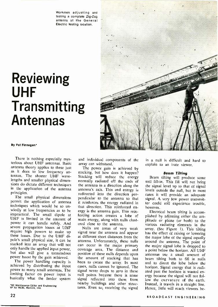
Workmen adjusting andtesting a complete Zig-Zagantenna at the GeneralElectric testing location.
ReviewingUHFTransmittingAntennas
By Pat Finnegan*
There is nothing especially mys-terious about UHF antennas. Basicantenna theory applies to these justas it does to low frequency an-tennas. The shorter UHF wave-lengths and smaller physical dimen-sions do dictate different techniquesin the application of the antennaprinciples.
The small physical dimensionspermit the application of antennatechniques which would be so un-wiedly at low frequencies as to beimpractical. The small dipole atUHF is limited in the amount ofpower it can handle safely. Andsevere propagation losses at UHFrequire high powers to make upthese losses. Due to the UHF di-pole's small physical size, it can bestacked into an array that will notonly handle the applied input power,but also will give a tremendouspower boost by the gain achieved.
The power handling capacity isachieved by distributing the inputpower to many small antennas. Thelimiting factor on power input isbasically what the feeder system
BE Maintenance Editor and EngineeringVP for WLBC, Wilkie, Ind.
and individual components of thearray can withstand.
The power gain is achieved bystacking, but how does it happen?Stacking will reduce the energynormally radiated off the ends ofthe antenna in a direction along theantenna's axis. This end energy isredirected into the direction per-pendicular to the antenna so thatit reinforces the energy radiated inthat direction. This reinforced en-ergy is the antenna gain. This rein-forcing action creates a lobe ofmain energy, along with nulls clust-ered close to the antenna.
Nulls are areas of very weaksignal near the antenna and appearat different short distances from theantenna. Unfortunately, these nullscan occur in the major primarycoverage area. The distance andposition of these nulls depends uponthe amount of stacking that hasbeen to create the array. In mostcases, nulls cannot be ignored. Thesignal never drops to zero in thesenull points because there is somesignal reflected into them fromnearby buildings and other struc-tures. Even so, receiving the signal
in a null is difficult and hard toexplain to an irate viewer.
Beam TiltingBeam tilting will produce some
null fill-in. This fill will not bringthe signal level up to that of signallevels outside the null, but in mostcases it will provide an adequatesignal. A very low power transmit-ter could still experience trouble,however.
Electrical beam tilting is accom-plished by adjusting either the am-plitude or phase (or both) to thevarious radiating elements in thearray. (See Figure 1). This tiltinghas the effect of raising or loweringthe major lobe of the signal equallyaround the antenna. The point ofthe major signal lobe is dropped toa point below the horizon. All UHFantennas use a small amount ofbeam tilting both to fill in nullsand to direct the lobe below thehorizon. Signal energy that is radi-ated past the horizon is wasted en-ergy because the signal will not fol-low the curvature of the earth.Instead, it travels in a straight line.Hence, little will reach viewers be -
22 BROADCAST ENGINEERING

yond the horizon.Mechanical beam tilting simply
tilts the antenna mast physically byinserting small shims under its base.This type tilting is sometimes usedto overcome local terrain problems.For example, a mountain top instal-lation may use some mechanical tiltto better direct the signal into thevalley it serves below. Only smallamounts of mechanical tilt are used.Tilting will change the "overturnmoment." The "overturn moment"concerns the ability to stay on topof the tower under stress from thewind, ice, and its own weight.
Bask TypesCommercial UHF television has
been serving the public for approxi-mately 18 years. The majority ofantennas in use today are basicallythe same two original types, theslotted and helix, while the zig-zagis a close second. While the modernantennas are more refined, they stilluse the basic principles of the origi-nals. The zig-zag arrived commer-cially about seven years ago and itis a close cousin to the helix. Thereare several versions of the zig-zag
MAJOR LOBE
TILTED DOWN
ELECTRICAL CENTER
OF ANTENNA
HORIZONTAL PLANE
MAJOR LOBETILTED DOWN
Fig. 1 Electrical beam tilt moves the major signal lobe down toward thehorizon. Field strength is lost in the horizontal plane, but better coverage isattained out to the horizon.
which go by different names ac-cording to the manufacturer. Otherantennas have been used, such asdipole arrays, and there have beensome custom built antennas. Thesetypes are in a minority comparedto the basic types.
There is one major differencebetween the slot and the solidresonant antenna. The polarizationof the fields will be opposite, thatis, the electric field of the slot willbe in the same direction as themagnetic field of the solid antenna.
You might better visualize howthe slot works if you consider thisanalogy. Visualize an isolated farmhouse at night with a light on inonly one room. The light will shinethrough the window and light asmall portion of the lawn. Considerthe light as the RF energy, thewindow as the slot and the windowglass as a radome.
Practical slot antennas make useof many slots and at different placeson the antenna structure. By prop-erly placing the slots, the directionof the signal can be controlled andby increasing the number of slots,the amount of energy radiated is
increased. Thus, both antenna gainand direction can be accomplished.
The Slotted AntennaThose who have worked with RF
circuits know how difficult it is toconfine RF energy. The slightestopening in shielding will allow theRF to escape.
The slot antenna is designed todo just that-allow the RF energyto escape from its containment, butin a prescribed and efficient man-ner. (See Figure 2). In a wave -guide or transmission line carryingRF energy at UHF frequencies, ifa slot is cut in the outer conductingsurface and if the slot is correctlyproportioned, RF current will flowlengthwise in the slot creating a
field across the width of the slot.This field will have the same di-mensions as the field produced bya solid resonant antenna. The lengthof the slot must be at least 1/2
wavelength long to radiate efficently.
The PylonThe pylon antenna is a slotted
type. The pylon forms a large trans-mission line. The steel outer cylin-
November, 1970 23

der forms the outer conductor,while the copper center line formsthe center conductor. The center isheld properly spaced from the steelpylon with teflon mounting pegs.The RF signal is fed either to thebase of the pylon or two a mid-point of the antenna through thecenter conductor, depending uponthe particular type of pyon involved.
As the RF energy travels alonginside the pylon, part of the energyis radiated from each slot. Ratherthan depend upon the RF naturallyflowing through the slot, a smallloop or bar is used at each slot to"scoop up" RF energy and moreefficiently couple it into the slot.The slot has a polyethylene coverwhich acts as a radome.
All the slots are normally fedin phase, which produces a broad-side array and the normal patternis circular. When electrical beamtilting is used, the phase of theRF fed to various slots is adjustedso as to produce the desired resultsin the vertical pattern. The earlymodels had an adjustable centerconductor harness so that beamtilting could be accomplished in thefield. The new models preset thedesired beam tilt and this can't bechanged once it has been set at thefactory.
WAVEGU I DE
SLOT
ELECTRIC
FIELDACROSS
SLOT
DIRECTION
OF
CURRENTFLOW
THROUGHSLOT
DIRECTIONOF RF
INSIDEWAVEGU IDE
Fig. 2 A half wave slot cut in the sideof waveguide. The RF current will flowlongways in the slot, creating an elec-trical field across the slot.
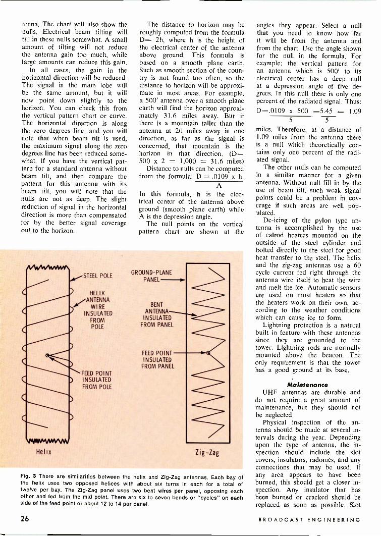
The Helix AntennaThe helix antenna works on the
principle of a traveling wave in along wire. (See Figure 3). When anRF signal is fed to one end of awire that is many times the lengthof the wavelength of the appliedsignal, radiation will take place asit travels along the wire. The ampli-tude of the signal will diminish asit progresses due to this radiation.If the wire is long enough, verylittle or no signal will reach the end,and there will be no reflections.Therefore, such a wire may be leftopened or grounded and there willbe no problems. Such a long wireis a non -resonant device.
The length of the helix used ina commercial antenna is about 12wavelengths long at the RF fre-quency. There are six turns of thehelix, and each turn about twowavelengths long. The helix isspiraled around a steel pole, sopositioned from the pole as to aidthe radiation from the helix.
The practice with commercialUHF helix is to use two helices perbay, opposed to each other andboth fed from a common feed point.The RF is fed from inside the steelpole, and the feed point at eachpair of helices is about 100 ohms.With each helix opposed to itspartner, the vertical componentscancel out, leaving only the hori-zontal components, which producea broadside array.
Bays may be stacked up to atotal of five and will produce again of 25. They may be rotatedin relation to the other bays, orthe length of the feder lines maybe varied to produce a shift inphase to individual bays to accom-plish electrical beam tilting.
The horizontal pattern may bedirectionalized by attaching smallstubs to the helices at appropriateplaces so as to distort the patterninto the desired shape. These smallstubs act as radiators to redirectthe RF energy into the directionsneeded.
The Zig-Zag AntennaThis antenna also works on the
traveling wave principle. In this an-tenna, the long wire is bent at halfwave intervals. When the wire isbent in this manner, phase reversalstake place at each interval whichcancels out the vertical components
of the signal. The zig-zag is a panelcontaining the bent wire insulatedfrom the panel at approximately 0.1to 0.2 wavelength. The panel worksas a ground plane to aid the radi-ation from the wire.
There are different varieties ofthe zig-zag made by various manu-facturers and they go by differentnames, such as the Zee Panel, V -Zee Panel, etc. Each type has itsown refinements. The V -Zee forexample, is also bent into a Vshape.
The zig-zag antennas have be-come quite popular because of theirversatility. Any number of panelsmay be used (within reason) andalmost any pattern for the signalmay be developed. A station mayorder a complete antenna from amanufacturer, which comes on itsown mast section and adjusted forthe desired horizontal and verticalpattern needed. This is a completeunit just as are the pylons andhelix antennas.
The panels may be mountedaround an existing tower structure.In addition to all the directionalhorizontal patterns possible with thezig-zag panels, a circular patternmay also be obtained.
Besides the stacked dipole arraysand other customized antennas,there has been a recent entry intothe field. This one makes use ofthe slotted antenna principle coupledwith parasitic elements to producehorizontal pattern shaping. Eachbay is fed internally from separatefeed lines from a power divider atthe base of the antenna. By vary-ing the phase to various bays, elec-trical beam tilting may be accom-plished.
Vertical PatternCharts or curves which display
the vertical pattern are usually aprofile view and then from onlyone side of the antenna. If onewere to turn the chart from itsstandard configuration to a positionso that the depression degrees areon the vertical side of the chart,then the lobe would point hori-zontally to the horizon. This willgive a better visualization of themain lobe of the pattern.
Nulls are created in the verticalpattern by stacking of antennas intoan array. Each antenna has a curvesupplied with it to show the verti-cal pattern of that particular an -
24 BROADCAST ENGINEERING
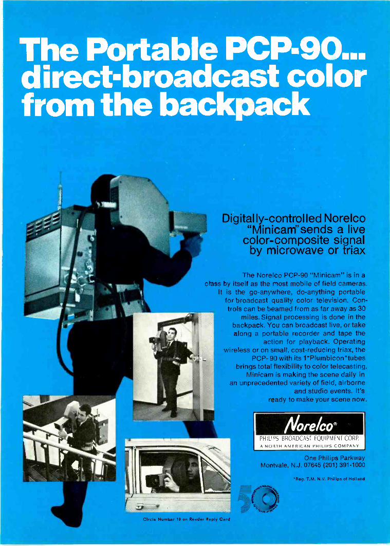
The Portable PCP -90...direct -broadcast colorfrom the backpack
Digitally -controlled Norelco"Minicam"sends a live
color -composite signalby microwave or triax
The Norelco PCP -90 "Minicar -W. is in aclass by itself as the most mobile of field cameras.
It is the go -anywhere, do -anything portablefor broadcast quality color television. Con-trols can be beamed from as far away as 30
miles. Sigral processing is done in thebackpack. You can broadcast live, or takealong a portable recorder and tape the
action for playback. Operatingwireless or on small. cost -reducing triax, the
PCP- 90 with its 1"Plumbicon*tubesbrings total flexibility to color telecasting.
Minicam is making the scene daily inan unprecedented variety of field, airborne
and studio events. It'sready to make your scene now.
NorelcoPHILIPS BROADCAST EQUIPMENT CORP.A NORTH AMERICAN PHILIPS COMPANY
'One Philips ParkwayMontvale, N.J. 07645 (201) 391-1000
'Reg T.M. N.V. Philips of Holland
Circle Number 18 on Reader Reply Card
tenna. The chart will also show thenulls. Electrical beam tilting willfill in these nulls somewhat. A smallamount of tilting will not reducethe antenna gain too much, whilelarge amounts can reduce this gain.
In all cases, the gain in thehorizontal direction will be reduced.The signal in the main lobe willbe the same amount, but it willnow point down slightly to thehorizon. You can check this fromthe vertical pattern chart or curve.The horizontal direction is alongthe zero degrees line, and you willnote that when beam tilt is used,the maximum signal along the zerodegrees line has been reduced some-what. If you have the vertical pat-tern for a standard antenna withoutbeam tilt, and then compare thepattern for this antenna with itsbeam tilt, you will note that thenulls are not as deep. The slightreduction of signal in the horizontaldirection is more than compensatedfor by the better signal coverageout to the horizon.
The distance to horizon may beroughly computed from the formulaD= 2h, where h is the height ofthe electrical center of the antennaabove ground. This formula isbased on a smooth plane earth.Such as smooth section of the coun-try is not found too often, so thedistance to horizon will be approxi-mate in most areas. For example,a 500' antenna over a smooth planeearth will find the horizon approxi-mately 31.6 miles away. But ifthere is a mountain taller than theantenna at 20 miles away in onedirection, as far as the signal isconcerned, that mountain is thehorizon in that direction. (D=500 x 2 = 1,000 = 31.6 miles)
Distance to nulls can be computedfrom the formula: D = .0109 x h.
AIn this formula, h is the elec-trical center of the antenna aboveground (smooth plane earth) whileA is the depression angle.
The null points on the verticalpattern chart are shown at the
STEEL POLE
HELIXANTENNA
WIREINSULATED
FROMPOLE
FEED POINTINSULATEDFROM POLE
Helix
GROUND -PLANE
PANEL
BENT
INSULATEDFROM PANEL
FEED POINTINSULATED
FROM PANEL
Zig-Zag
Fig. 3 There are similarities between the helix and Zig-Zag antennas. Each bay ofthe helix uses two opposed helices with about six turns in each for a total oftwelve per bay. The Zig-Zag panel uses two bent wires per panel, opposing eachother and fed from the mid point. There are six to seven bends or "cycles" on eachside of the feed point or about 12 to 14 per panel.
angles they appear. Select a nullthat you need to know how farit will be from the antenna andfrom the chart. Use the angle shownfor the null in the formula. Forexample: the vertical pattern foran antenna which is 500' to itselectrical center has a deep nullat a depression angle of five de-grees. In this null there is only onepercent of the radiated signal. Thus:D=.0109 x 500 =5.45 = 1.09
5 5
miles. Therefore, at a distance of1.09 miles from the antenna thereis a null which theoretically con-tains only one percent of the radi-ated signal.
The other nulls can be computedin a similar manner for a givenantenna. Without null fill in by theuse of beam tilt, such weak signalpoints could be a problem in cov-erage if such areas are well pop-ulated.
De-icing of the pylon type an-tenna is accomplished by the useof calrod heaters mounted on theoutside of the steel cylinder andbolted directly to the steel for goodheat transfer to the steel. The helixand the zig-zag antennas use a 60cycle current fed right through theantenna wire itself to heat the wireand melt the ice. Automatic sensorsare used on most heaters so thatthe heaters work on their own, ac-cording to the weather conditionswhich can cause ice to form.
Lightning protection is a naturalbuilt in feature with these antennassince they are grounded to thetower. Lightning rods are normallymounted above the beacon. Theonly requirement is that the towerhas a good ground at its base.
MaintenanceUHF antennas are durable and
do not require a great amount ofmaintenance, but they should notbe neglected.
Physical inspection of the an-tenna should be made at several in-tervals during the year. Dependingupon the type of antenna, the in-spection should include the slotcovers, insulators, radomes, and anyconnections that may be used. Ifany area appears to have beenburned, this should get a closer in-spection. Any insulator that hasbeen burned or cracked should bereplaced as soon as possible. Slot
26 BROADCAST ENGINEERING

ANTENNA WIRE
A 1 t` INSULATORS
......"---GROUND PLANEPANEL
B
C
ANTENNA WIRE
INSULATORS
*--- GROUND PLANEPANEL
Fig. 4 Part A shows an end view of aZee Panel. Fig. 4b is an end view of aZee-Vee Panel bent Zig-Zag antenna.And Fig. 4c shows how Zee-Vee panelsmay be side mounted around a tri-angle tower. Here the panels aremounted so as to "fire" at a tangentto the tower.
covers that may be missing orcracked also should be replaced assoon as possible.
Painting of the antennas shouldbe done with care. The paintersshould be careful to avoid paintinginsulators on the slot covers. Ifthese areas are painted, the effi-ciency of the antenna will be im-paired.
When workmen must climb overthe antenna to make inspections orto change the beacon lamp, theymust be careful to use the climbingspikes and not climb on the antennaelements.
The impedance match of the an-tenna should be good across thebandpass. These are broadband an-tennas for the channel, but dam-aged elements, moisture and dirt in-side a pylon, cracked insulators etc.can change these characteristics sothat a good impedance match maynot be retained across the bandpass.
The antenna should have a check-out before installation on the tower.This will show up any damage thatmay have occurred in shipment.This checkout is the same as thetransmission line checkout forVSWR. An RF signal generator,slotted line and dector are used tocheck the VSWR across the band-pass. These original figures shouldbe preserved for future reference.
After the antenna is installed onthe tower and the line itself has
been checked out into a dummyload, the antenna should be at-tached to the line and then an over-all check of both line and antennamade. The combined VSWR read-ings may vary slightly, because inmost cases the antenna will not pre-sent as good a load as the dummyload. Should there be any markedchanges in the readings, further in-vestigation should be made of theantenna. It may have had somedamage while it was pulled up andmounted on the tower. Again, thisoriginal set of readings should bepreserved for future reference.
The line and antenna systemshould be checked at least once ayear for any changes in the VSWRreadings across the bandpass. Agood time to do this would be atthe annual Proof time.
When de-icers are used, theyshould be checked out each fall be-fore the winter season sets in. Theseshould be turned on so that theyhave a chance to heat up while theclimber is going up the tower. Youshould feel these to determine thatall of the heaters are working.
When heaters are separate elements,one or more individual elementsmay burn out. This can be worsethan no heaters at all, as parts ofthe antenna may be iced while partis clear. It would be better that theantenna is done evenly, whether itbe iced or melted clear.
Antenna problems can show upas a mismatch to the line. Mismatchon the line will cause reflectionsback down the line and there willbe ghosts in the picture, and theVSWR readings will increase. Prob-lems in the line itself can appear inthe same manner at the transmitterlocation, so it is sometimes difficultto determine which one is at fault.The only sure way to isolate theproblem to antenna or line is bybreaking the line and terminating itwith a resistive dummy load.
Outside maintenance programsare vitally important. But we tendto forget about towers, antennas,transmission lines and dog houses.And as simple as this type ofmaintenance may seem, trouble out-side can keep you off the air longerthan most inside problems.
1.0
.5
5
A FIELD IN HORIZONTAL PLANEIS DOWN 5%
B ANTENNA IS UNING 0.5° BEAM TILT
NULL POINTS
400' ANT.
C 1. 56M I .
D 0.84M1.
E 0.6mi.
1,000 ANT
3. 9M I.
2.1M1.
1.5M1.
1 0
+ -2 3 4 5
DEGREES BELOW HORIZONTAL
6 7 8 9
Fig. 5 A typical vertical pattern ciart for a medium gain antenna. This pattern showsthat a 1/2 degree beam tilt has been employed and shows the result. Distance tothe three null points have been computed for two antenna heights. Distances areapproximate and have been rounded off.
November, 1970 27

The FirstVideo TapeCartridgeSystem
Here is another interest leader in the longline of equipment being developed today thatmay become the necessity of tomorrow. Sincethe introduction of this machine, Ampex, asexpected, has developed a video cart system.
By Harry Etkin
One of the equipment "stars" ofthe 1969 and 1970 NAB conven-tions was the Video Tape CartridgeSystem by RCA. A "first" in thebroadcast equipment industry, thesystem was introduced in 1969 asa prototype and demonstrated as apre -production model at the con-vention just passed.
The cartridge system provides anautomatic facility for recording andplaying back any type of programmaterial in segments of up to threeminutes duration. The possible ap-plications of this equipment go be-yond the obvious station -break for-mat. The new machine will handlesports clips, promos, news featuresor any other short segments of upto three minutes.
Up to this time, the trend in videotape machines was to provide com-plex and expensive equipment, withthe broadcaster obtaining less em -Levittown, Pa.
Fig. 1 RCA video tape cartridgeunit, 1970 version.
phasis in schedule flexibility. Fur-ther, market studies show that onthe average the useful time of videotape machines is only 12 percent;the rest of the program day is spentin "standing by" for an on -air cueor in awaiting a taping assignment.
The new video tape cartridge sys-tem promises to change this. Justwhat does it have to offer? The pur-pose of this article is to discuss thebasic technical principles and pro-vide a summation of what the videocartridge can do for the TV station.
Basic CapabilitiesThe new Cartridge System con-
sists of a video tape cartridge whichis utilized as a carrier for each re-corded segment. This equipment isnot just used as an automatic car-tridge playback unit, but it can alsorecord cartridges. In normal use ithas the capability for playing backthe cartridges one after another pro-ducing a complete, continuous pro-gram. The system will replay as
many as 22 video tape cartridges,each containing up to three min-utes of commercials, news or otherprogramming, automatically and inany pre -determined sequence ac-cording to the way the cartridgesare loaded. This is achieved by in-cluding two tape decks or playbackstations within the equipment. Feed-ing these two tape decks is a car-tridge changer mechanism holding22 tape cartridges. (See Figure 2.)
The equipment is programmed toplay a sequence merely by placingthe appropriate cartridges in thechanger mechanism in the order inwhich they are to be programmed.The equipment is started by activat-ing a play cue -up mode, the appro-priate sequence command is en-tered, and a play command is in-itiated by a single push button. Thisdescription introduces the basicequipment capability, to help under-stand the full range of programmingpossibilities in this equipment thevarious concepts of the system will
28 BROADCAST ENGINEERING

be discussed in greater detail.
Cartridge Unit AssemblyThe tape cartridge shown in Fig-
uge 1 consists of a protectivemolded plastic covering and approx-imately 21/2 x 31/2 x 5 inches, whichholds two small spools of two-inchquadruplex video tape. Althoughthe cartridge is miniaturized, it pro-vides proper tape handling whenplaced in the equipment and fur-ther adequate tape protection out-side of the equipment. The tape iscompletely protected against dam-age or deterioration by doors onthree sides of the cartridge whichare normally closed but open auto-matically when the cartridge reachesthe playing station of the equipment.
The presented maximum tape ca-pacity of the cartridge is usually 236feet of usable tape length plusleader and tail, which carries a -pro-gram playing time of 3 minutes withone recording standard and one tapespeed at 15.0 in/sec for 525 -line
Fig. 2 Cartridge changer mechanism.
television systems. The recordedprogram contains several cue markswhich are necessary for the properoperation of the system. These cuemarks are placed on the tape auto-matically when a cartridge is re-corded. The recorded presentationon the tape is the same as the
TART OF TAPE
highband quadruplex reel-to-reeltapes.
Automatic CueingNote that in Figure 3 the car-
tridge tape is controlled by twopermanent mechanical cue marks lo-cated near the ends of the tape. Thecue marks are normally used to pre -
TART Of TAPE MARKER
,)
51
236 FLUSAGLE TAPE LENGTH(LONG PLAY CARTRIDGE)
ENO Of TAPE MARKER
END OF TAPE
Fig. 3 Cue marker locations.
November, 1970 29

vent the tape from being completelyunwound under any condition inthe equipment. As a matter of factthe start -of -tape marker provides abench mark for recording.
To place the unit in a recordingposition, the start -of -tape marker isautomatically located and the tapeis prepared to begin a recording. Asseen in Figure 4, the recorded tapeneeds two additional magnetic tonemarks on the cue track to performthese important functions. This pro-vides exact determination of the lo-cation and duration of the actualprogram segment.
The start -of -message (SOM) tonemark is located exactly two secondsbefore the start of the active pro-
gram. This tone mark determinesthe exact point where the equip-ment will start the playback oper-ation. During normal operation theunit must be given a two secondpre -roll command when playing thecartridge system. It will start up andprovide a fully synchronized colorpicture in less than two seconds sothat the signal could be put on theair two seconds after start up.
Ten seconds before the end ofthe program an eight second end -of -message (EOM) tone mark is lo-cated. It is positioned during record-ing by establishing the system's du-ration of program time. The markcan also be repositioned to correctan improperly recorded tape. The
START OF TAPE
START OF TAPEMARKER
START OF PROGRAMCUE
LEADER'','4,1tt7
SEC Of RECORDINGFOR OVERRUN
2 SEC MINISO SEC MAX (LONG PLAY CARTRIDGE) -.1
,If \`CTIVE PROGRAM
1.-4 SEC -42SEC4
ENO OF PROGRAMCUE
10 SEC
ENO Of TAPE
ENO OF TAPEMARKER
Fig. 4 Sequence of marker operations.
GUIDE ROLLER
HE ADWHEEL
R/P HEAD
- CARTRIDGE
TAKEUP REEL
SUPPLY REEL
GUIDE POST
CAPSTAN
Fig. 5 Tape transport and automatic threading mechanism.
trailing edge of the eight -secondtone mark is provided for the startpulse to the next cartridge in a se-quence so that the two second pre -roll is automatically provided.
Threading MechanismThe cartridge system equipment
includes a tape transport and anautomatic threading mechan ismwhich is illustrated in Figure 5, andfunctions in the following manner.In order to thread the tape throughthe vacuum guide and around therest of the tape path, a specialmechanism extracts a loop of tapefrom the cartridge and places thetape in the operating path. Thethreading mechanism then retractsso that it does not interfere withplayback, record, or rewinding ofthe tape in the normal tape path.When the play or record cycle iscompleted, the tape is automaticallyrewound past the start -of -messagemark. Therefore, the threadingmechanism extends and removes thetape from the tape path, and thetape loop is drawn back into thecartridge. This completes a thread-ing cycle and the cartridge is thenavailable to be removed from theplaying station.
Changer MechanismFigures 2 and 6 present the Car-
tridge Changer mechanism whichcarries and handles 22 cartridges.A belt with 22 bins and two trans-fer stations is located above the en-trance to each playing station.Transfer station A is on the topleft side and transfer station B ison the top right side of the beltchanger mechanism. The cartridgesare transferred from the bin to theplaying station by a pair of armswhich move downward to engagethe cartridge on its recessed plateat the rear. The arms then movehorizontally back into the equip-ment to put the cartridge into theplaying position. When a play orrecord cycle is completed, the trans-fer arms then engage the cartridgeand move it back into the bin withthe doors closed.
Sequence of OperationThe video cartridge tape recorder
is compact, versatile and simple tooperate. On a cartridge, preloadedwith one to three minutes of tape,there is enough time to handle com-mercials, promos and news clips.
30 BROADCAST ENGINEERING

A unique pair of Planar Triodes40 kW peak at 1500 MHz -15 kW peak at 3000 MHz
The TH 318, specially designed for pLlsed oscil-lator service, delivers up to a 40 kW peak pcwer out-put at 1500 MHz with a duty cycle of .003 Its pre -stretched grid structure completely eliminates gridresonances; and all -metal -and -ceramic ccnstructionassures exceptionally long service life, as demon-strated by hundreds of tubes in field use.
The TH 6886 delivers up to 15 kW peak at 30000MHz with a duty cycle of .001. Its planar structure,
s m lar to tie TH 318, g ves it the same ruggednessaid resonarce-free operation.
Both tubes are particularly suitable for dopplerradar appii:ations because of their very low noiselevel. And they join the most comprehensive line oftriodes anc tetrodes developed for operation up to20 kW CW 3t 1000 MHz For more specific informa-tior, please circle the appropriate number on theReader Service Card or contact us directly.
THOMSON - C SF Thompson-CSF Electron Tubes, Irc./50 Rockefeller Plaza / New York, N.Y. =0020 (212) 489-0400
Circle Number 19 on Reader Reply Carc
November, 1970 3I

Now let's look at how this mecha-nism is controlled to play a se-quence of cartridges. Here is a stepby step description of the variousoperational functions of the RCAvideo cartridge tape recorder.
Th equipment control system pro-vides all the facilities for playingcartridges in a continuous sequence,when they are properly loaded inthe belt. Normally, the cartridgesare loaded into their bins on thebelt starting with Bin Number 1.Figure 6 shows the numbering ofthe sequential bin locations in thebelt. When the HOME mode is ac-tivated, the belt will move so thatBin Number 1 is indexed at play-
ing Station A. To play a sequence,the PLAY CUE mode is activated.This starts a sequence of opera-ations which results in both A andB playing stations being loaded,threaded, and cued up. After thiscycle of operation is finished, indi-cators will show the operator thatthe PLAY CUE function is com-pleted, and the unit is now readyto accept a play command.
The PLAY CUE mode operationcauses cartridge Number 1 to beloaded in Station A. After this ispositioned, the belt moves threespaces to the right which then posi-tions Bin 2 at Station B. The Bin 2cartridge is then transferred into
Transfer Station A Transfer Station B
0
91
0LI
091
.._
gl0000VI £1 ZI
Fig. 6 Belt changer mechanism.
I PLAYS VIDEOSWITCH
4 -ACTIVE PROGRAM*
c5END CUE UNTHREAb
STATION-WI 4-2 SEC
A2 SEC -w4
CHANGER
BELT
STATIONB
UNLOADSI
'PLAY'
VIDEOSWITCH
THREAD, ACTIVE PROGRAM,* 3 -0.1CUE lf 5,END CUE
IP L AT 141-10 SEC -41
I VLOAD 1 EXTERNAL
CUE
ADVANCE5
ADVA2NCE
2 2E2-.1END CUE
ADVANCE2
ADVANCE+ 3
UNLOADSo. 2
ACTIVE PROGRAM* 2 -.NI
LOAD*4
THREADCUE
REWINDUNTHREADUNLOAD 3
THREADCUE 5
CUED]
Fig. 7 Cartridge sequence of operation.
Station B and the belt at once shiftsthree spaces back to the left. Thisoperation prepares the changemechanism to accept cartridgeNumber 1 back in the bin after ithas been played.
As each cartridge is transferredinto a playing station, that particu-lar station will automatically threadthe tape into the tape path andthen advance the tape in a forwardrun direction until the start -of -mes-sage cue is located. The tape willstop at this point and the playingstation is now ready for a play com-mand. Station A is then started inthe play mode when the play com-mand is given. (See Figure 7.)
The equipment servo systemshould produce a fully synchronizedcolor picture in less than two sec-onds. Two seconds after start theactive program material will follow.After Cartridge 1 is played through,the end cue of Cartridge 1 is de-tected at ten seconds before the endof the program on Cartridge 1. Thetrailing edge of Cartridge 1 end cuethen starts the B playing station attwo seconds before the end of theprogram on Cartridge 1. Two sec-onds after the start of Station B itwill be fully synchronized and theprogram will be automaticallyswitched from Station A to StationB. This program switch process isaccomplished during the verticalblanking interval.
After the program switch to Sta-tion B, Station A automatically re-winds Cartridge 1 until the start ofmessage cue is passed. When Car-tridge 1 has stopped and unthreadedfrom the tape path it is unloadedback into Bin 1. The belt thenmoves two spaces to the left whichbrings Bin 3 into position at StationA. Again the thread and cue cycleis activated on the cartridge in Bin3 which has been transferred intoStation A. When threading and cue-ing of Cartridge 3 is finished it isready to accept a start trigger. Af-ter Cartridge 3 has been transferred,the belt moves five spaces to theright. It then puts Bin 2 at StationB ready to receive Cartridge 2 whenits cycle has been completed.
As Cartridge 2 continues to playin Station B and when the trailingedge of the end cue from this car-tridge is passed, a start trigger isdirected back to Station A. StationA, which now contains Cartridge 3,begins running and after two sec -
32 BROADCAST ENGINEERING

Fig. 8 Display of the electronics layout and cartridge tape belt.
onds the program switches back toStation A. Now Station B goesthrough the cycle of rewind, un-thread, unload, advance belt, load,thread, and cue to ready Cartridge4. The operational cycle of remov-ing one cartridge and readying thenext one in the same playing sta-tion should take a little less than20 seconds. Therefore, the shortestprogram segment which can be se-quenced continuously is 20 seconds,although either the first or last seg-ment in a sequence can be pro-duced at a shorter length of time.In many cases, the cueing systemis capable of handling segmentlengths down to two seconds.
The "Automatic Sequence Regis-ter (ASR)" provides a means toprogram the number of commercialsin a given sequence. This is a de-sirable feature because the sequen-tial process described above wouldbe endless once started with onecartridge triggering the next one.This condition would continue un-til an empty bin was reached or theequipment manually stopped. Theoperator normally adjusts the sys-tem to indicate how many cartridgesto play in sequence for each playcommand.
In the "Master/Slave Mode" twoindependent automated VTR sys-tems are coupled together with acommon control and video process-ing. As the video playback signalelectronics are identical to those inpresently available highband VTR's,economy is achieved when the car-tridge system uses the signal elec-tronics from the existing reel-to-reel
VTR. In this mode the cartridgesystem is the "slave" to the reel-to-reel VTR which then becomes the"Master". The Master/Slave selfcontained system is performed bymodifying the master equipment toprovide an FM switch to provide aswitching facility between the nor-mal FM output of the reel-to-reelelectronics and the output of thecartridge slave unit. This procedureis arranged to switch during the ver-tical blanking interval with the servosystem of the master unit modifiedso that an excellent video switchtransition would be possible be -between the master equipment andthe cartridge.
With the Master/Slave system it isassumed possible to insert a se-quence of cartridges and go frommaster machine to the cartridgeplayback, change or re -cue the tapeon the master while the cartridgesare playing, then go back to themaster unit at the end of the car-tridge sequence.
Recording TechniquesThe broadcaster will note that the
cartridge system contains facilitiesfor easily recording any type of ma-terial on a cartridge including filmor live segments in a sequence, with-out complications. Related to thebasic part of the system is the cap-ability of placement of cue -markson the tape during a recording ses-sion. The system also provides ameans for pre -roll of external equip-ment during recording so that arecording can be accurately started.Looking at Figure 4, it will be seen
that exactly seven seconds of thesignal should be recorded on thecartridge ahead of the active pro-gram material. If a program wasbeing recorded from a reel-to-reeltape, it would be necessary to cueup the tape recorder at less thanminus six seconds so as to insurethat it would be fully stabilized bythe time the minus six second pointis reached. The cartridge unit atthis point should be started in therecord mode.
An automatically recorded for-mat for a VTR needing a six sec-ond stabilization time and a re-quired 13 second pre -roll will bedescribed. The VTR would be cued13 seconds prior to the start of theprogram; by using the proper con-trol on the control panel it would beplaced under remote control of thecartridge recorder. The RECORDbutton is pressed; this will then pro-duce a PLAY trigger which willstart up the external VTR.
After six seconds the cartridgemachine will start in the RECORDmode and begin recording. Two sec-onds later the start of program cuewill be recorded and at 13 secondsthe program will begin. The pro-
now being recorded and atten seconds prior to the end of theprogram the end of the program cuethen begins recording. This will con-tinue for eight seconds and up totwo seconds before the end of pro-gram. The video and audio contin-ues to be recorded until two sec-onds beyond the end of the pro-gram. The system then automaticallyrewinds the cartridge and sets it upin the PALY CUED condition forthe desired preview by the opera-tor. If a preview is not required, areject condition is installed.
The Video Cartridge Tape Re-corder, can be used as two auto-mated video tape recorders, an au-tomatic cartridge changer and a pro-grammable control R -R system.Figure 8 presents the electronicslayout of the VCTR.
A less complex andlower pricedVCTR should be developed and in-troduced for use in CATV, educa-tional/instructional, public broad-casting, research, medical and lab-oratory outlets. This would providea challenging facility and put a newdimension in the recording andplaying of any type of material, in-cluding programming possibilitieswith a wide range of applications.
November, 1970 33

The move toward bidirectional CATVBy Leo G. Sands*
The FCC has joined the advo-cates of maximum utilization ofCATV facilities. This can only beachieved by providing bidirectionaltransmission facilities. The originalpurpose of CATV was to pipe tele-vision programs into areas wheredirect off -the -air pickup of TV sta-tions was poor or not possible. NowCATV systems are in operation, orare to be installed, in areas serveddirectly by TV stations, includingmajor cities. In such areas there isoften a need for bidirectional trans-mission capability.
The concept of bidirectionalCATV is not new. A few yearsago the author wrote a series of12 articles about CATV for a tele-phone industry magazine in whichit was stressed that telephone com-panies planning to install CATVtransmission facilities should ser-iously consider making them bidi-rectional. It was pointed out thatthe same facilities could be usedfor bidirectional telephone, data andCCTV transmission, in addition tounidirectional TV program trans-mission.
Shortly thereafter, the author'sfirm was engaged by a blue chipcorporation to conduct a study todetermine the feasibility of install-ing a two-way coaxial cable systemto serve a metropolitan area with apopulation of almost 1,000,000.When asked what capabilities wererequired, the client's representativesaid "surprise us."
It was found that the client couldoffer the following facilities andcapabilities to the community:
(1) nine channels of programspicked up from commercialand educational TV stations,two closed circuit educa-tional TV channels, onelocal -origination TV pro-gram channel, FM band ra-
dio, and a music channel,for transmission to CATVsubscribers.
(2) two or more closed circuitTV and audio channels fortransmission to subscribersto special services (businessnews, medical, etc.).
(3) 50 private telephone chan-nels for use by the citygovernment.
(4) closed circuit TV surveil-lance of parks, schools, ma-jor intersections and otherpublic properties.
(5) bidirectional closed circuitTV transmission betweenschools.
(6) bidirectional data transmis-sion between schools.
(7) bidirectional data transmis-sion between hospitals.
(8) bidirectional data transmis-sion between hospitals anddoctors' offices.
(9) bidirectional data transmis-sion for business and in-dustry.
(10) Pickup of signals for low -power police walkie-talkiesand transmission of theaudio to police headquarters.
Trunk CablesBecause of the large geographi-
cal area to be covered, trunk cablelengths would have been excessiveif the conventional system configu-ration were employed. Instead, itwas determined that the head endshould be in the center of the city,adjacent to the railroad station.From the head end the plan calledfor running eight trunk cablesthrough railroad -owned under-ground ducts in the downtown areaand attached to railroad -owned tele-phone poles in other areas. The dis-tribution cables would be run un-derground in some areas, on powercompany poles elsewhere.
All trunk cables would beequipped for bidirectional transmis-sion. Distribution cables and dropswould be unidirectional except thoseto be used for picking up signals.The head end would function as aswitching center where signals com-ing in on one trunk at frequenciesbelow 46 MHz could be routed outon one or more trunks at frequen-cies above 50 MHz.
The basic system plan calls forbidirectional through a single cableinstead of separate cables for each
50-220MHz
5 -46MHz
High pass
filter..1 50-220 MHz
AMP
F re q Selective Couplers
Low pass
filter5 -46 MHz
AMP
High pass
filter
Low pass
filter
MHz
. 0
5-46MHz
BE CATV Editor and presidentof Leo G. Sands & Assoc. N.Y.
34
Fig. 1 Bidirectional repeater.
BROADCAST ENGINEERING

direction of transmission. Signalsabove 50 MHz are to be transmittedoutward from the head end, andsignals below 46 MHz inward tothe head end.
Where to get all of the necessaryhardware was a problem. It still is,but will become less of a problemwhen equipment manufacturers cansee that the market for two-wayCATV hardware is not too far off.
Trunk Cable RepeatersThe plan calls for two basic types
of trunk cable repeaters-one typeconsisting of two amplifiers andfilters, as shown in Figure 1-theother type consisting of one ampli-fier and a filter network, as shownin Figure 2. Every trunk repeateramplifies signals in the 50-220 MHzrange. Some also amplify signals inthe 5-46 MHz range (Figure 1);others simply pass signals in the5-46 MHz range around the 50-220MHz amplifier (Figure 2). Twotypes of repeaters are required sincesignals in the 5-46 MHz range re-quire amplification at fewer pointsthan higher frequency signals. Filtersare required to prevent "singing."
To insert signals for transmissioninward to the head end, a repeatersuch as shown functionally in Figure3 would be required. And to bothdrop and insert signals, a repeaterconfigurated as shown in Figure 4would be required. Hardware forassembly of these various types ofrepeater stations is available.
The greatest difficulty was find-ing a source of telephone circuitchannelizing equipment. If conven-tional telephone carrier equipmentwere to be used, it would have beennecessary to provide group modula-tors, and the equipment would havebeen costly. When various telephoneequipment manufacturers wereasked if they could supply modula-tors that would operate within the42-46 MHz range, and demodula-
tors that would operate within the72-76 MHz range, the answer was"no."
A radio equipment manufacturer,however, offered to design and fur-nish low -power AM or FM modu-lators and demodulators at muchlower cost than conventional tele-phone carrier equipment. Each tele-phone circuit would be terminated
as shown in simplified form in Fig-ure 5.. At a police/fire call box, nobell would be required. Taking thehandset off the hook would activatethe modulator and demodulator.The modulator carrier signal wouldcause an off -hook indication to bereceived at the switchboard. Atthose locations where a telephonebell would be required, in -band or
50 -220MHz
5 -46 MHz
Frequency Selective Couplers_....-50-220MHz
5-46 MHz
Fig. 2 A repeater with passive low band path.
50-220 MHz
5-46 MHz
High
Pass
Filter
__...150-228 MHz
AMP
FREQUENCY -SELECTIVE
rCOUPLERS
Low
Pass
Filter
D rectional
Coupler
5-46 MHzSigrals
High
Pass
Filter
Low
Pass
Filter
50-220 MHz
5-46 MHz
Fig. 3 Repeater with signal' insert facility.
November, 1970 35
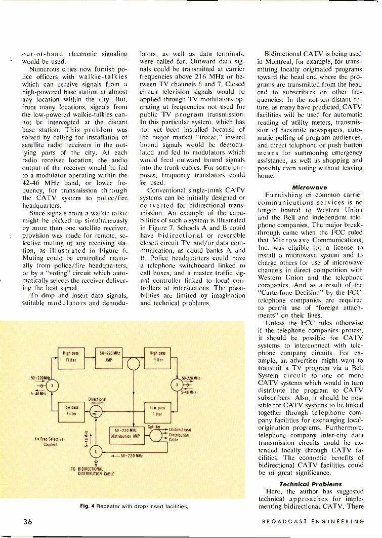
out -of -band electronic signalingwould be used.
Numerous cities now furnish po-lice officers with walkie-talkieswhich can receive signals from ahigh-powered base station at almostany location within the city. But,from many locations, signals fromthe low -powered walkie-talkies can-not be intercepted at the distantbase station. This problem wassolved by calling for installation ofsatellite radio receivers in the out-lying parts of the city. At eachradio receiver location, the audiooutput of the receiver would be fedto a modulator operating within the42-46 MHz band, or lower fre-quency, for transmission throughthe CATV system to police/fireheadquarters.
Since signals from a walkie-talkiemight be picked up simultaneouslyby more than one satellite receiver,provision was made for remote, se-lective muting of any receiving sta-tion, as illustrated in Figure 6.Muting could be controlled manu-ally from police/fire headquarters,or by a "voting" circuit which auto-matically selects the receiver deliver-ing the best signal.
To drop and insert data signals,suitable modulators and demodu-
lators, as well as data terminals,were called for. Outward data sig-nals could be transmitted at carrierfrequencies above 216 MHz or be-tween TV channels 6 and 7. Closedcircuit television signals would beapplied through TV modulators op-erating at frequencies not used forpublic TV program transmission.In this particular system, which hasnot yet been installed because ofthe major market "freeze," inwardbound signals would be demodu-lated and fed to modulators whichwould feed outward bound signalsinto the trunk cables. For some pur-poses, frequency translators couldbe used.
Conventional single -trunk CATVsystems can be initially designed orconverted for bidirectional trans-mission. An example of the capa-bilities of such a system is illustratedin Figure 7. Schools A and B couldhave bidirectional or reversibleclosed circuit TV and/or data com-munication, as could banks A andB. Police headquarters could havea telephone switchboard linked tocall boxes, and a master traffic sig-nal controller linked to local con-trollers at intersections. The possi-bilities are limited by imaginationand technical problems.
High pass
Filter
0
5-46MHz
low pass
Filter
X. Freq Selective
Couplers
50-220MHz
AMP
Directionalcoupler
High pass
Filter
low pass
F.Iter
50-220 MHz
Distribution AMP
Splitter
-6-50-220 MHz
TO BIDIRECTIONALDISTRIBUTION CABLE
50-220MHz
5-46MHz
Unidirectional
DistributionCable
Fig. 4 Repeater with drop/insert facilities.
Bidirectional CATV is being usedin Montreal, for example, for trans-mitting locally originated programstoward the head end where the pro-grams are transmitted from the headend to subscribers on other fre-quencies. In the not -too -distant fu-ture, as many have predicted, CATVfacilities will be used for automaticreading of utility meters, transmis-sion of facsimile newspapers, auto-matic polling of program audiences,and direct telephone or push buttonmeans for summoning emergencyassistance, as well as shopping andpossibly even voting without leavinghome.
MicrowaveFurnishing of common carrier
communications services is nolonger limited to Western Unionand the Bell and independent tele-phone companies. The major break-through came when the FCC ruledthat Microwave Communications,Inc. was eligible for a license toinstall a microwave system and tocharge others for use of microwavechannels in direct competition withWestern Union and the telephonecompanies. And as a result of the"Carterfone Decision" by the FCC,telephone companies are requiredto permit use of "foreign attach-ments" on their lines.
Unless the FCC rules otherwiseif the telephone companies protest,it should be possible for CATVsystems to interconnect with tele-phone company circuits. For ex-ample, an advertiser might want totransmit a TV program via a BellSystem circuit to one or moreCATV systems which would in turndistribute the program to CATVsubscribers. Also, it should be pos-sible for CATV systems to be linkedtogether through telephone com-pany facilities for exchanging local -origination programs. Furthermore,telephone company inter -city datatransmission circuits could be ex-tended locally through CATV fa-cilities. The economic benefits ofbidirectional CATV facilities couldbe of great significance.
Technical ProblemsHere, the author has suggested
technical approaches for imple-menting bidirectional CATV. There
36 BROADCAST ENGINEERING

72-76 MHz
42-46 MHz
To drop/insertrepeater or
bidirectional
distribution cable
Demodulator
Frequency -selectiveCoupler
Modulator
Hybrid To
Telephone
Fig. 5 Telephone circuit termination
are problems, however, since co-axial cable is not a perfect trans-mission medium nor is all of thenecessary hardware fully adequateand available off the shelf. Greatstrides have been made in improv-ing CATV amplifier performance,making it practical to use frequen-cies other than TV channels 2through 13.
Many of today's technical prob-lems, encountered when using ana-log transmission, will not existwhen digital transmission techniquesare refined. Marconi (in England)has already announced the develop-ment of a PCM (pulse code modu-lation) system capable of simulta-neous transmission of up to 200color TV channels through wave -guide. It should be possible totransmit a lesser number of chan-nels through coaxial cable. A sis-ter company, Canadian Marconi, ismarketing a PCM system for trans-mission of data and up to 120 voicechannels which can use microwaveor coaxial cable as the transmissionmedium. It should be feasible touse such PCM equipment in a bi-directional system by applying thehead end bound PCM signals di-rectly to the cable, and the outwardbound signals through an RF mod-ulator. It should also be possibleto transmit television and other ana-log signals over the same cable atthe same time.
One Cable Or Two?The $64 question is: "should one
cable be used for bidirectional trans-mission, or should separate cablesbe used for each direction?" Fromthe standpoint of simplification oftechnical problems, the answer is:
Frequency -selective
coupler
42-46MHz
72-76 MHz
Decoder
To drop insert
repeater or
bidirectional
distributio cable
Radio
Receiver
Fig. 6 Radio receiver terminal.
Head end
School B
Bank B
_PoliceHgtrs
Police Call Boxes
and Traffic Signals
To DistributionCables
9
10
Bank A
School A
Far end Distribution AMP
Fig. 7 Example of bidirectional CATV capabilities.
"two cables, if not more." Consider-ing the cost and vulnerability ofelectronic hardware to failures, itmight be more economical in thelong run to use two or more cables.
The simplest way to convert aunidirectional CATV system intoa bidirectional system is to piggy-back a second system, transmittingin the reverse direction, on thesame poles. This doubles the in-vestment in cable and amplifiers,and could pay off if the operatorhas a large enough market for spe-cial services and is an aggressivesalesman. The less costly alternativeis to have a consultant, or an equip-ment manufacturer, redesign thesystem for bidirectional transmis-sion through the existing cable.
When starting from scratch, it isa different ball game. Cable in-stallers can almost as readily in-stall a dual or multi -tube coaxialcable as a single -tube coaxial ca-ble. It doesn't cost much more forlabor to install two ampilifers in-stead of one at each amplifier lo-cation. Which route to take shouldbe resolved on an individual casebasis. What is best under one setof circumstances, might be follyunder another. The main point tobear in mind is that a single coaxialcable can handle up to about 300MHz of information. Two can han-dle up to 600 MHz. Economically,it's a matter of how much revenueeach MHz will produce, and atwhat initial and operating cost. A
November, 1970 37

Avoiding
Lightning Damage
to power suppliesBy Horace N. Smith
110
Fig. 1 left 7200 volt primary, 3 phase.Fig. 2 right 7200 volt primary with 2 phases, each above ground.
With the coming of any new de-vice in engineering (such as solidstate devices), there are alwaysthings that come up unexpectedlythat the designer cannot forsee.
In the case of solid state powersupplies for medium powered trans-mitters that operate from threephase power lines, it seems verysimple to replace the six rectifiertubes with solid state silicon diodesand eliminate the tubes and extrafilament transformers. In actualpractice, this is true most of thetime. However, there is one appli-cation that apparently needs morecapacity built into the system thanthe ordinary specifications call for.
The case in point is a transmit-ter power supply using a 220 voltthree phase power line circuit toprovide 4100 volts DC at 1 amp. Inthe conventional three phase en-trance system from the power com-pany there are three complete trans-formers, either wound separately orwound on one set of laminations.In either case, there are three pri-mary and three secondary windings.These are usually connected ineither a "Y" or a "Delta" connec-tion or a combination of both. InFigure 1 the primary is Delta andthe secondary is connected "Y".There are other ways to make theconnections, depending on the cus-tomers' need for various types ofcurrent and voltage combinations,or sometimes circuits are differentdue to the choice of a power com-pany engineer.
The secondaries in Figure 1 willprovide 220 volts between any twoof the "hot" wires and 110 voltsbetween any hot wire and thegrounded neutral. The 220 voltssplit with a grounded neutral is theconventional voltage used in mosthomes and businesses. Also, 220
*Chief Engineer at WERK and WCTW.
38 BROADCAST ENGINEERING
AKG
A IC I;
C -451EMicrophoneSystem
thecommon-senseapproach tophantompowering.
Just one ortwo resistors!Simple, isn't it?
No AC power supplies required
No DC power supplies
No "central" power supplies
No special "cards"
Operates off any DC voltage between7.5 and 52v (including the standard24v available in most equipment).
Stabilizes its own operating voltage,to maintain constant output level.
Optimum polarization voltage,for best signal-to-noise ratio.
MICROPHONES HEADPHONESDISTRIBUTED BYNORTH AMERICAN PHILIPS CORPORATION100 EAST 42,10 STREET. NEW YORK. NEW YORK 10 011
AEG CANADA - )IVISION OF DOUBLE DIAMOND ELECTRONICS SCARBOROUGH, -ONTARIO
5101 30
THESIMPLICITY
OFSIMPLEXING
The AKG C -451E may be powered at thecost of one or two precision resistors: Noseparate AC or DC power supplies re-quired nor special "cards" or "central"power supplies at additional cost.The microphone preamplifier requires aslittle as 7.5v DC and may be operateddirectly off the standard 24v B+ supplyavailable in your equipment (or any othervoltage between 7.5 and 52v). The cur-rent consumption is only 2.8 mA.
Other featuresunique with the AKG system are:A) Stabilized operating voltage: The DCsupply voltage to the microphone is notrequired to be particularly well regulatednor is it rigidly tied to a specific voltage.In fact, it may vary by ± 15% since theC -451E preamplifier will stabilize theoperating voltage. There is no limit tothe number of microphones to be pow-ered off your console.B) Constant 60 volts polarization volt-age: 60 volts is the optimum polarizationvoltage for highest performance stand-ards, specifically sensitivity; resulting inmore gain without increase in noise level -and better signal-to-noise ratio. TheC -451E supply voltage is not simultane-ously the polarization voltage (too low).The microphone preamplifier provides aconstant 6C volts polarization voltageand fluctuation in the supply voltage willnot change the output level of themicrophone.There are no short cuts in the AKGC -451E circuitry!
HOW DOES DT SOUND?Interestingly enough, its pick-up charac-teristics are being compared to the qual-ity previously obtained only with largediaphragm condenser microphones.The newly developed CK-1 capsule incor-porates a metallic alloy diaphragm (simi-lar to the diaphragm material used inmeasuring microphones) and is abso-lutely smooth between 30-18,000 Hzwith unequaled transient response char-acteristics and wide dynamic range.The polar pattern is a true cardioid at allfrequencies with linear off -axis accep-tance and a front -to -back discriminationof 20-30 dB over the entire range.Last, but not least, a practical and eco-nomic modular design permits you tochoose from a variety of interchangeablecapsules with different response charac-teristics and polar pattern (cardioid,omni-directional, figure -eight and shotgun tube).
AKGOFFERS A CHOICE -NOT A STANDARD
Write fo- complete technical data.Circle Number 20 on Reader Reply Card
Noyeml)er, 1970 39

volt three phase is available powerby using all three hot wires. Thepower company may use a smallertransformer on one side of the threephase line to complete the threephase circuit with larger transform-ers on the side or phase that sup-plies the single phase power to thestation. This allows both single andthree phase power from the one setof transformers.
The exception to the typical cir-cuit hookup is found when a radiostation is located in a rural areaor on the outskirts of a city whereonly two phases of a line are avail-able or where there is only singlephase power and the power com-pany wants to run only one morephase to the station to save on con-struction costs which could runinto thousands of dollars. In thistype of situation there are usuallytwo phases plus a ground or neutralsupplied in the primary circuit ofthe power line.
In a small or medium poweredstation, the two phase hookup willprovide ample power at a savingsto the power company. When thetwo phases are provided, the hookupis usually made as in Figure 2. Theprimaries and secondaries are con-nected in an "Open Delta" style.The angle between the phases is120°, with two phases providedmaking 240° used, this leaves 120°across the remaining open circuitwhich is correct for three phaseoperation.
The voltage across the secon-daries in Figure 2 windings AA' &BB' have 220 volts each and arein series. However, due to the phasedifference, the total voltage acrossthem on wires 4 and 7 is another220 volts which completes the threephase supply and will operate equip-ment just as any three phase con-ventional hookup will do.
In order to get 220/110 volt
single phase power for other use,one of the 220 volt windings is splitwith a center tap and grounded fora neutral as is winding BB' withwire 6 in Figure 2. This leaves wire4 with about 205 volts aboveground; however, this posses noproblems for a three phase trans-former or motor, since their wind-ings are isolated from ground.Transformer BB' and BB is usuallylarger since it provides the singlephase current for the station suchas light, heat and other power.
The problem with this type ofconnection apparently shows up onlyduring a lightning storm or whenthe power company is making andchanging connections. As you cansee in Figure 2, there is no thirdwinding across either the primaryor secondary transformers and thisleaves the connection between wires4 and 7 in series with the windings.If any power surge, such as a light-ning hit or unusual connectionchange is made, where a currentis induced in both windings at thesame instant and in the same di-rection, a double voltage will ap-pear between wires 4 and 7 evenif there are provisions by the powercompany to keep all voltages withincertain limits.
This extra surge of voltage hasnever caused much of a problemwith rectifier tubes since they willwithstand a great voltage surgewithout damage for the very shortperiod of time involved. However,with silicon diodes, any voltage overthe rated PIV may cause damageeven though it may last only a fewthousandths of a second. In thepower supply at WIUC, Winches-ter, Indiana this voltage surge wouldknock out one side of the rectifierbank each time the sky would getblack and lightning was noticed inthe community. The rectifiers wererated at 10,000 volts PIV and were
providing 4100 volts DC. In theaverage circuit and conventionalhookup, this rating would seemmore than adequate. But the volt-age across the open side would risehigh enough to damage the recti-fiers, since there is no winding thereto absorb any extra current andkeep the voltage down.
After checking out the transmit-ter circuits and making a drawingof the power company's connection,it appeared that a simple solutionwould be to increase the peak in-verse rating of the rectifiers. Thiswas done with a complete set ofrectifiers installed in series with theones already in service. This in-creased the PIV of each diode sec-tion to 20,000 volts. Actually, therectifiers across the side where theopen voltage appears would be allthat is necessary for the modifica-tion. It did seem advisable to re-inforce the entire set of rectifiersto prevent any further trouble. Dur-ing the last two summer seasonsthere have been numerous electricstorms and for the first time sincethe station went on the air, theyhave had no problem in a storm andapparently no power supply dam-age. There is no change in trans-mitter operation due to the modifi-cation and no change in perfor-mance.
Some "Open Delta" circuitswould be more susceptible to dam-age than others, depending on thetype of area, the distance of thelines involved and many otherthings such as power factor angle,and power company condensers tokeep the voltage and current inphase. If any station is having thistype of difficulty, it might be wellto check and see if the situationis similar to that of WIUC. (SeeRobert Jones' article on tower staticin the October, 1970 issue of Broad-cast Engineering.)
40 BROADCAST ENGINEERING

for small market stationsthe field lens position of the mul-tiplexer. The results were amazing.In fact, Weisensell and Clyman,who had battled the color imbalancefor four years, were amazed at howunbalanced the light sources were.
The specially purchased GE grayscale which is used for adjustmentsof the lamps of both the slide andfilm projector, showed that therewas an excess of light in the filmchain. Both the slide projectorwhich uses a 500 watt lamp andthe film projectors which use 300vatt lamps had more than enoughqht needed to operate effectively,d the imbalance between the two'it sources was marked.The WMTV engineers did not
discover this earlier, according toWeisensell, because the film pro-jectors were adjusted by a grayscale that was purchased in 1966and could only be used in adjust-ing the film projectors. The newgray scale, which is used in adjust-ing both the film and slide pro-jectors, led the WMTV staff to tryfiltering of the slide projector lightand then adjusting the light sourceof the film projectors.
"We knew we had too muchlight on the slides," stated Weisen-sell, "So we figured if we decreasedthe light in the TP-7 projector, wecould begin balancing the slide andfilm color."
With a Kodak CC 30C filter on
the slide projector and voltages ad-justed on the lamps by means ofVariacs in the TP-66s and by add-ing a Variac to the TP-7, the pro-jectors could be balanced and thecolor problem was virtually solved.
The ultimate touch was the de-cision to use the same Ecktachromestock for slide and develop it inthe same chemicals as the film. Thefinal solution to color imbalance atWMTV was a story of cooperationand a combination of skills andtechniques.
A similar system for color bal-ance is planned by Weisensell forWMTV's sister station, WSAU-TV,a Forward Communications stationin Wausua, Wisconsin.
new LSC VEDETTE
16mm and 35mm PROFESSIONAL PROJECTORS
for fast, safe, high speed viewing andinspection of motion picture film
The ideal machine for film qualitycontrol, timing and correction, andrelease print inspection. Handlesnegatives, fine grains and prints.
Visual inspection of both pictureand optical sound track. Solid stateamplifier for simultaneousmonitoring of picture and sound.
Efficient revolving prism shutterand sharp optics produce bright.clear images without overheatingfilm.
Smooth, gentle film handling at upto 400 ft./min., without intermittentmovement of usual claw or Genevagear drive. Stable, positive focus.2,000 foot film capacity.
Write for LSC Vedette literatureor request a "no obligation"demonstration.
ULTRASONICCLEANER
for MOTION PICTURE FILM MICROFILM
MAGNETIC TAPEPresented The Academy of Motion Pictures Arts and Sciences Award of Merit
for Outstanding Technical Achievement.
Ultrasonic energy is the most effec-tive and economical way tocompletely clean motion picturefilm, microfilm and tape withoutmechanical scrubbing and wiping.Ultrasonic energy performs theentire cleaning operation.
Restores clarity and sound tomaximum quality.
Enhances the entertainmentvalue of motion picture film andimproves commercials.
Assures static free film with colorbalance undisturbed.
Cuts projector maintenancecosts ... no dirt or dustcarried into gates and orifices ...less breakdowns.
Completely automatic ...requires only loading andunloading.
LIPSNER-SMITH CORPORATION7334 No. ClErk St., Chicago,111. 60626 312-338-3040
Costs only 1/20 of a penny perrunning foot to operate.
Used by every major motionpicture lab in the world.
Descriptive brochurewill be sent on request
10041
Circle Number 21 on Reader Reply Card
November, 1970 43

+ Testing Transistorsdr-7-4
By CarlBE Solid
BabcokeState Editor
No bench should be without acommercial transistor beta andleakage tester. If transistors re-placed the vacuum tube, somethingmust replace the tube checker. Inthis series we think you'll pick upmain and backup methods forchecking transistors. Let's try thebeta test.
DC beta is the ratio of collector
current versus base current. Mostcommercial transistor testers varythe base current until a pre -deter-mined amount of collector currentis read on the meter, then the meteris switched to read the base current.The meter scale is calibrated asDC beta.
We should understand the sig-nificance of such tests to avoid mis-
Table 1-Ohmmeter and beta testsof three power transistors. negative
lead to:positivelead to:
meter readingscale: in ohms:
2N408 germanium PNP forward base emitter X10 31
low power -low voltage outputtransistor DC beta 150-allleakages normal on
forward
leakage
base
emitter
collector
base
X10
X1OK
29
1M
transistor tester leakage collector base X1OK 700K
C/E forward collector emitter X100 6000
C/E leakage emitter collector X1K 200K
2N301A germanium PNP forward base emitter X10 16
high power -medium voltagetransistor DC beta 130-slight,normal ICE° leakage
forward
leakage
base
emitter
collector
base
X10
X1K
15
45K
leakage collector base X1K 33K
C/E forward collector emitter X100 70
C/E leakage emitter collector X100 8K
NPN silicon leakage base emitter X1M 500M
medium power -high voltagetransistor DC beta 70-allleakages normal on transistor tester
leakage
forward
base
emitter
collector
base
X1M
X10
200M
110
forward collector base X10 104
C/E leakage collector emitter X1M 21M
C/E forward emitter collector X1M 180M
Ohmmeter function of a VTVM used for measurements; battery 1.5 volts.
44 BROADCAST ENGINEERING
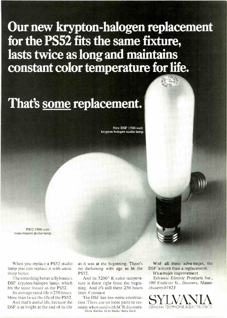
Our new krypton -halogen replacementfor the PS52 fits the same fixture,lasts twice as long and maintainsconstant color temperature for life.
PS52 1500 -wattincandescent studio lamp.
When you replace a PS52 studiolamp you can replace it with some-thing better.
The something better is Sylvania'sDSF krypton -halogen lamp, whichfits the same fixture as the PS52.
Its average rated life is 250 hours.More than twice the life of the PS52.
And that's useful life, because theDSF is as bright at the end of its life
New DSF 1500 -wattkrypton -halogen studio lamp.
as it was at the beginning. There'sno darkening with age as in thePS52.
And its 3200° K color tempera-ture is there right from the begin-ning. And it's still there 250 hourslater. Constant.
The DSF has low -noise construc-tion. There are no loose parts to res-onate when used with SCR dimmers.
Circle Number 22 on Reader Reply Card
With all these advaltages, theDSF is more than a replacement.
It's a major improvement.Sylvania Electric Products Inc.,
100 Endicott St., Danvers, Massa-chusetts01923
GENERAL TELEPHONE & ELECTRONICS

interpreting the DC beta reading atester might give us. So many tran-sistor types have been manufacturedthat a transistor testing manualgiving the control settings of thetester to permit the use of a good/bad scale is not always practical. Inaddition, the beta reading varieswith the collector current used dur-ing the test. We must decide thelimits that are acceptable in betareadings, often without sufficient in-formation on which to base thisjudgment.
A transistor with a DC beta of150 does not automatically producetwice the AC gain of another tran-sistor of the same type which readsa beta of 75. There are several rea-sons why this is true. The samecircuits that stabilize against unde-sired changes because of heat vari-ations also partially stabilize against
variations in average emitter cur-ren. Therefore the more effectivethe heat stabilization of the circuit,the less AC gain variation whentransistors of different DC beta areused.
A transistor with a low DC betamight produce normal gain if thecircuit can supply the added basecurrent. However, the input resist-ance of the transistor will be lowerand this could have a noticeableeffect on AC gain because of thechange in impedance matching.
Ohmmeter TestsOhmmeter tests of germanium
type transistors and diodes are quiteuseful, but are of questionable valuewhen checking silicon deviceswhose normal readings are nearlyan open circuit.
Table 1 compares the ohmmeter
TO OHMMETER
ACTUAL
ACTUAL
NPN
(A)
NPN
(B)
NPN
TURN ON-.
(C) TO OHMMETER
EQUIVALENT
27K
TURN-OFF1.5 1.5-
EQUIVALENT
Fig. 1 Simple turn-off and turn -on tests of transistors. (A) The collector -emitterresistance increases when the base is connected to the emitter. A fairly good test.(B) The collector -emitter resistance decreases when the base is connected to thecollector. A false test of no value. (C) A switch, resistor and two batteries permitturn-off, turn -on and ohmmeter tests. Accurate judgement of the transistor can beobtained, but leads must be changed during the tests.
readings of three different outputtransistors. Readings are actuallythose of individual transitors anddo not represent average conditions.Notice that only the forward biasreadings of base -emitter and base -collector of the silicon transistor arelow enough to have any significancein an ohmmeter test.
Some of these ohmmeter read-ings will change as the heat nearthe transistor changes. Also, thetable does not show the completelydifferent readings obtained whenanother ohmmeter battery is sub-stituted.
Despite all these limitations,nearly all germanium and manysilicon transistor defects can befound with ohmmeter tests, becauseborderline or questionable resultsare seldom obtained.
Turn -Off and Turn -On TestsOhmmeter readings combined
with simple turn-off and turn -ontests provide an easy method ofdetermining leakage and the abilityof the base to control collector -emitter current.
The collector -emitter resistance(in the forward bias polarity) in-creases when the base is connectedto the emitter, as shown in FigureI a. This is true (but not complete)transistor action, because a smallamount of voltage is developed be-tween base and emitter when thebase is floating, and this voltageacts as forward bias on the baseto reduce the collector -emitter re-sistance. Connecting the base to theemitter is a simple turn-off test.
The circuit of Figure lb shouldbe a simple but good turn -on test.A low reading on the ohmmeterresults when the base is connectedto the collector. But examine thediode equivalent schematic. Thepositive ohmmeter lead is now con-nected to the base, which is forwardbiased relative to the emitter, andwill measure as a low resistance.This is a false turn -on test and hasno value.
True transistor action can betested by the circuit shown inFigure lc, which keeps the collectorisolated from the base as the base
46 BROADCAST ENGINEERING

is supplied with forward -bias, noexternal bias, or reversed bias. Ex-perience shows .the test results tobe very good, but the operationaldrawback of changing leads bringsthe possibility of poor connectionand loss of time.
A complete adapter that providesall connections for ohmmeter, turn-off and turn -on tests is shown inFigure 2. Neither the transistor northe ohmmeter leads require revers-ing or changing, and a transistorcan be identified as a PNP or aNPN by the readings obtained byswitching the position of SI.
The 2N408 used to obtain thereadings in Table 1 measured 200ohms on the turn -on position ofS2, 6K -ohms on the C -E position,and about 100M -ohms on the turn-off position. No hair-splitting deci-sions are necessary to judge that Fig. 2 Complete schematic of an adapter yot.. can build that permits turn-off, turn -ontransistor to be normal! A and ohmmeter tests without moving ohmmeter or transistor clip leads.
TO OHMMETER
D
-I 1.5 -TT -1.5
0C -E
B -C fi TURN-OFF
B -E V V TURN -ON
BLUE TO
COLLECTOR
27K
'3...GREENTO BASE
YELLOW TO
EMITTER
0
Neve
SOUNDCONTROLEQUIPMENT
Incorporates 26 f ul I mixingequalized input channels eachwith microphone and line in-puts. There are eight outputtracks with three mixed downgroups for stereo and monomastering, six echo groups,studio foldback, and an impres-sive list of built-in equalizers,compressors and other signalprocessing devices. A compre-hensive communications sys-tem links the Studio floor,balance engineer, projectionroom and the producer.The Neve organization spe-cializes in the design andinstallation of complex pro-fessional control consolesand systems for clientsthroughout the world.
Telephone 076 386 776 (Ten lines) Telex 81381
Rupert Neve & Co. Ltd. Cambridge House, Melbourn, Royston, Herts, England.
November, 1970
Circle Number 23 r.,n Reader Reply Card
47
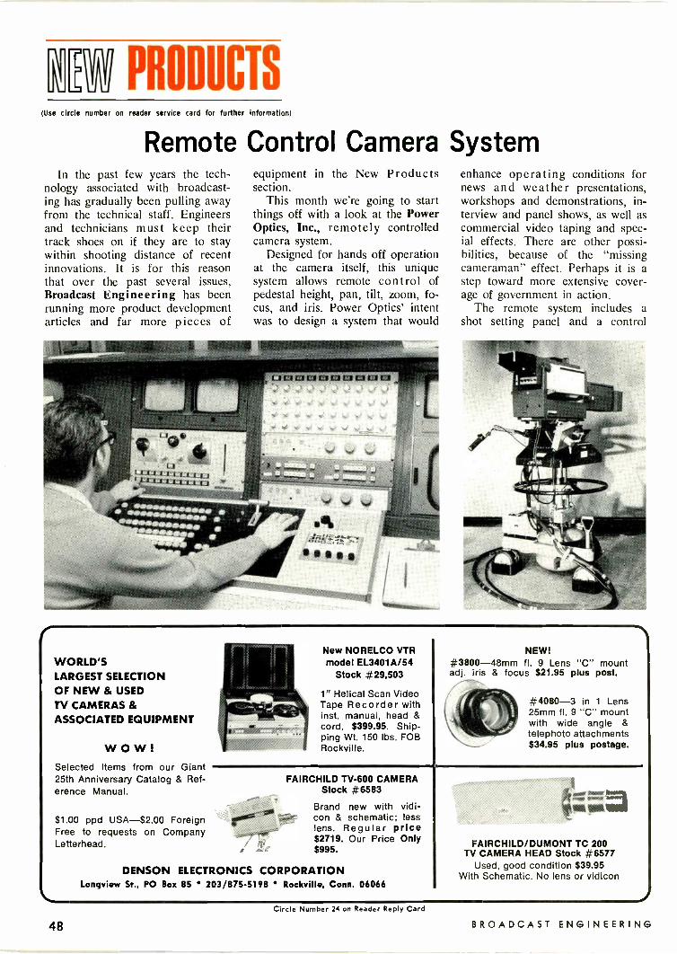
En PRODUCTS(Use circle number on reader service card for further information)
Remote Control Camera SystemIn the past few years the tech-
nology associated with broadcast-ing has gradually been pulling awayfrom the technical staff. Engineersand technicians must keep theirtrack shoes on if they are to staywithin shooting distance of recentinnovations. It is for this reasonthat over the past several issues,Broadcast Engineering has beenrunning more product developmentarticles and far more pieces of
equipment in the New Productssection.
This month we're going to startthings off with a look at the PowerOptics, Inc., remotely controlledcamera system.
Designed for hands off operationat the camera itself, this uniquesystem allows remote control ofpedestal height, pan, tilt, zoom, fo-cus, and iris. Power Optics' intentwas to design a system that would
enhance operating conditions fornews and weather presentations,workshops and demonstrations, in-terview and panel shows, as well ascommercial video taping and spec-ial effects. There are other possi-bilities, because of the "missingcameraman" effect. Perhaps it is astep toward more extensive cover-age of government in action.
The remote system includes ashot setting panel and a control
WORLD'SLARGEST SELECTIONOF NEW & USEDTV CAMERAS &ASSOCIATED EQUIPMENT
WOW!Selected Items from our Giant25th Anniversary Catalog & Ref-erence Manual.
$1.00 ppd USA-$2.00 ForeignFree to requests on CompanyLetterhead.
New NORELCO VTRmodel EL3401A/54
Stock #29,503
1" Helical Scan VideoTape Recorder withinst. manual, head &cord. $399.95. Ship-ping Wt. 150 lbs. FOBRockville.
NEW!#3800-48mm fl. 9 Lens "C" mountadj. iris & focus $21.95 plus post.
#4080-3 in 1 Lens25mm fl. 9 "C" mountwith wide angle &telephoto attachments$34.95 plus postage.
DENSON ELECTRONICS
FAIRCHILD TV -600 CAMERAStock #6583
Brand new with vidi-con & schematic; lesslens. Regular price$2719. Our Price Only$995.
CORPORATIONLongview St., PO Box 85 203/875-5198 Rockville, Conn. 06066
MIN ~Aawl HMI
fA set
FAIRCHILD/DUMONT TC 200TV CAMERA HEAD Stock #6577
Used, good condition $39.95With Schematic. No lens or vidicon
Circle Number 24 on Reader Reply Card
48 BROADCAST ENGINEERING

panel. The shot panel provides forup to 10 shots, each of which maybe pre-set during rehersal. Eachshot is recalled on the air by press-ing the appropriate buttons. How-ever, on -air adjustments can bemade on the control panel.
The picture, taken at WUTR,shows that the shot setting paneluses a series of color coded func-tion potientiometers allowing maxi-mum presetting of controls. Tomeet the specifications in the typeof control required for each func-tion, the pots use different turn ra-tios.
Circle Number 55 on Reader Reply Card
Equalizer -AmpInput Modules
The new Model 711L is thefirst of a new series of low -noiseaudio equalizer -amplifier inputmodules for microphone and/orline level inputs developed by theElectrodyne Corporation, an MCATech Company, Los Angeles, Cali-fornia. It consists of a microphonepre -amplifier, a straight line attenu-ator, input selector switch, Eq. am-plifier and a program amplifier.
Front panel controls allow 12 dBboost and attenuation and recipro-cal equalization curves for each of8 frequencies which permits equali-zation of the low, mid range andhigh frequencies. Four high fre-quency and two of the low fre-quency curves can be selected asshelving or peaking curves. A phasereversal push button switch is pro-vided to give 180° phase shift tothe incoming signal. One echo sendpot and selector switch gives theoperator the choice of echo sendfrom ahead of attenuator, ahead ofattenuator but after equalization, orafter attenuator and equalization.
Equivalent input noise is -127dBm, with gain rated at 70 dB. Twomicrophone input impedances, 50and 200 ohms, are provided. Lineinput impedance is 10K ohm bridg-ing. All output impedances are de-signed for 600 ohm lines. Actualoutput impedance is less than 50ohms.
Even greater flexibility is offeredthrough the input selector lever-adual concentric switch-which al-lows selection between microphoneand line. There are two positionsfor the line with a 20 dB pad to
ERASERECORD
REPROVIteEMONO - STEREOProfessional Direct Replacement Heads withcomplete written and pictorial instructions
Our factory will clean, rebuild. adjust and test yourhead ASSEMBLY... install new M M I heads...replace minor hardware and modify your gateto accept our "NON - POPPING" springs
r-40
36 HOUR SERVICE - LOANERS AVAILABLE
(612) 884-7393
MINNEAPOLIS MAGNETICS, INC.8125 PLEASANT AVE. SO., MINNEAPOLIS, MINN. 55420
STUDIOMONITOR
AMPLIFIERSby
Gz-sar-siL,D40
compactdelivers 40w RMS/channel at 412takes 13A" rack space, weighs 81/2 lbs.IM distortion less than 0.3% from
1/10w to 30w at 812S/N 100dB below 30w outputprice - $229 rack mount
D150
delivers 150w RMS both channels 812IM distortion less than 0.1% from
1/10w to 75w at 812S/N 100dB below 75w outputtakes 51/4" rack space, weighs 16 lbs.price - $439 rack mount
DC300
powerdelivers 300w RMS/channel at 412IM distortion less than 0.1% from
1/10w to 150w at 812S/N 100dB below 150w output at 812Lab Standard performance and
reliabilityprice - $685 rack mount
All Crown amplifiers are warranteed3 years for parts and labor. Theyare 100% American -made to profes-sional quality standards. All arefully protected against shorts, mis-match and open circuits. Construc-tion is industrial grade for yearsof continuous operation.
=.01-0-14®011-10Circle Number 42 on Reader Reply Card
November, 1970
BOX 1300, DEPT. BE, ELKHART, INDIANA 46514Circle Number 43 on Reader Reply Card
49

A Perfect Matchfor all yourTV Support
Requirements
QUICK -SET
TRIPODS DOLLIESHEADS PEDESTALS
Four basic product lines (Husky,Sampson, Hercules, Gibralter)with a wide range of variationsallows you to specify the exactsupport equipment for your spe-cific function and price range.We'll be glad to help you with yourselection . . . complete catalogavailable.
QUICK -SETINCORPORATED8121 Central Park Avenue
0
SKOKIE, ILL.
New Products(Continued from page 49)
compensate for high level input sig-nals.
A microphone pre -amp gain con-trol is provided, allowing up to 50dB gain in the microphone position.Other positions provide 10, 20, 30and 50 dB attenuation. The latter(-50 dB) position is desirable forhandling the high signal levels ofmodern condenser microphones.This position will allow signal lev-els as high as +18 dBm. The sizeof the module is 14" x11/2" x 41/4".
Circle Number 56 on Reader Reply Card
Variable Speed TurntableA continuously variable speed
turntable, introduced a decade agofor the monaural era, has been re-designed to meet today's stereoneeds.
Manufactured by Rek-O-Kut, adivision of CCA Electronics Cor-poration, the CVS-12 turntable isavailable independently or can befurnished with a custom base, pro-fessional tonearm and stereo cart-ridge. The system is identified asCVS-12S.
The turntable can be used by
both professional broadcasters andby schools, sports arenas, amuse-ment parks and wherever there isneed for continuously variable speedeffects.
Typical applications range fromproducing sound effects in the radiobroadcasting studio to furnishingmusical backgrounds in schools,skating rinks, amusement and sportsarenas. It is ideally suited for squaredance music and dance instruction.
Circle Number 58 on Reader Reply Card
Low Power FM TransmitterWe've been running behind on
low power transmitters, but here'sone from Ampex, the TD -7020.The TD -7020 is just one of a seriesof Ampex low power rigs. Theseries was designed for educationalFM broadcasting and for STL (stu-dio to transmitter link) service. Fourmodels using direct crystal -con-trolled cascade modulation areavailable.
The TD -7020 model offers fullstereo with one SCA channel. TheTD -7120 is monaural only, 7220 isstereo only, and the TD -7320 ismonaural with one SCA channel.
(Continued on page 52)
Vertical Interval SwitcherVisual Electronic Corporation an-
nounces the introduction of its newModel 24-10 Vertical Interval Pro-duction Switcher. Shown here isfirst production model sold toKBTV, Denver, Colorado.
The production switcher acceptscomp or non -comp signals on anyinput, automatically adding sync tothe non -comp signals. Automaticsynchronous -non - synchronous de-tection with mix -effects lockout isbuilt-in. Easily adjustable delays
eliminate coiled coax cable delayand cable cutting for delay match-ing. As an additional feature foruse with character generators, thenon -additive mix module includesremote color saturation and herecontrols mounted on the switcherpanel plus black border insertionfor high contrast characters onlight backgrounds. Yes, Visual is
still in the thick of it.Circle Number 57 on Reader Reply Card
Circle Number 26 on Reader Reply Card
50 BROADCAST ENGINEERING

"Scotch"BrandColor VideoTape guardsitself against damage.
Guards against cinching. "Scotch" Brand No. 400 now solves yourvideo tape handling and shipping problems. A new, matte -finish back treatmentvirtually eliminates cinching, windowing and creasing.Capstan slippage is a thing of the past.
Guards against scratching. The exclusive treatment on "Scotch" BrandNo. 400 resists scratching, eliminates polyester redeposits on the oxide surface.Prevents the increase of dropouts and effectively extends tape life.
Guards against dust damage. This highly conductive treatment reducesstatic attraction of contaminants that can damage tape and VTR heads.New No. 400 gives you built-in protection, plus performance -the finest value in color video tape. COMPANY
"SCOTCH', IS A REGISTERED TRADEMARK OF CO.
SEE US AT THE NAEB SHOW. BOOTH NO. 71 AND 72.Circle Number 27 on Reader Reply Card

PROFESSIONALPRODUCTS FOR
PROFITABLEBROADCASTING
1AUTOMATIC
TRANSMITTERLOGGING
WITH
ACCURACYOF 0.1%
OR BETTER
MODEL ADP -220AUTOMATIC
DATA PRINTER
MOSELEYASSOCIATES, INC.
lid, I Lie Park1 1 1 CASTILIAN DRIVEGOLETA. CALIF. 93017
(8051 968-9621
Circle Number 28 on Reader Reply Card
,,,,_ ,.. ...a, ........._
TapeCartridges
11*-iaior
--..
*
Li...- .
All lengths and sizes stocked - fastservice - highest qualitySeries UnitType Time at 71/2 ips Price
300 20 sec. (13') $ 2.00300 40 sec. (25') 2.05300 70 sec. (44') 2.10300 100 sec. (63') 2.25300 140 sec. (88') 2.35300 3'/2 min. (132') 2.50300 51/2 min. (207') 2.90300 81/2 min. (320') 3.70300 101/2 min. (394') 3.90300 empty cart. 1.60600 16 min. (600') 6.25600 empty cart. 2.80
1200 31 min. (1163') 10.45
Also: DL cartridges (for Spotmasterdelay machines), bulk tape, tape -tagsand other accessories.ANY ASSORTMENT-NO MINIMUM ORDER
BROADCAST ELECTRONICS, INC.A Filmways Company
8510 Brookville Rd., Silver SpHng, Md. 20310
(Continued from page 50)
Metering consists of an audiolevel meter to indicate correctmodulation level and individual me-ters for RF power output, final ampcurrent, and final amp voltage.
No external accessories areneeded. The compact self-containedunit is designed for table top op-eration.
Circle Number 59 on Reader Reply Card
TV MonitorRank Precision Industries, Inc.
has introduced two new Mono-chrome TV Monitors in the NorthAmerican Market.
Housed in a contemporary teak-wood cabinet, the Monitors, whichoffer quality monitor performance,are available with either a 20 -inchor 24 -inch screen. The cabinets
make the units ideal for use inexecutive offices or for educationaland industrial or other TV useswhere exposed cabinets are re-quired.
The Monitors are equipped with4 x 3 aspect ratio tubes whichmake possible reduced scan view-ing, utilizing maximum screen area.A black -level clamp assures a highdegree of stability and, Rank ex-plains, clarity for the high resolu-tion pictures produced on bothMonitors.
Six channel capacity is availablefor both audio and video input onboth units, and ease of installationis enhanced by a choice of either110V or 220V power input.
Circle Number 60 on Reader Reply Card
Dynamic MicrophoneA new Ultra-Cardioid dynamic
microphone featuring a 25 dB front -to -back rejection ratio that mini-mizes reverberation and microphoneplacement problems is now avail-able from The Astatic Corporation,Conneaut, Ohio. Designated Asta-tic Model 811, the new microphone
utilizes an exclusive sintered phos-phor bronze (SIBROPHASE)acoustic filter to assure positivephase shift and directional charac-teristics that result in good controlof feedback.
II la
The effects of "pop," "blast", andwind are substantially reduced bya grille assembly consisting of astainless steel mesh that enclosesa foam filter and a fine magneticscreen which effectively preventsdust and magnetic particles fromreaching the diaphragm.
The 811 has a unidirectional(cardioid) polar pattern and a fre-quency response of 40-15,000 Hz.Simple adjustment of a solderlessconnection permits the selection ofeither high impedance (EIA 40,000ohm) or low impedance (EIA 150ohm). Sensitivity at high impe-dance is -50 dB re: IV/microbar.At low impedance, the sensitivityis -54 dB re: 1 mw/10 microbars.
Special shielding reduces hum toa negligible level in environmentswhere electrostatic or magneticpick-up may be a problem. Humpick-up is attenuated to -121 dBmre: .001 Gauss, 60 Hz.
Circle Number 61 on Reader Reply Card
Photo ConductiveColor Telecine
Rank Precision Industries,Broadcast Division will introducetheir first 3 -tube PhotoconductiveColour Film Telecine at the Inter-national Broadcast Convention.This will be a 16 mm Uniplex equip-ment capable of extension to a fullMultiplex format by adding a fur-ther 16 mm or 35 mm film projec-tor and a 60 slide projector. A revo-lutionary feature is the departurefrom the normal "island" philoso-phy and the adoption of an "in -line" format.
Both the camera head and con-trol unit have been specially de -
52 BROADCAST ENGINEERING

signed and built for the new tele-cine, all film loading operations canbe carried out from one side, thereare only two fixed angle movingmirrors on the multiplexer and twolamps ensure a continuous lightsource in each projector.
Circle Number 62 on Reader Reply Card
CATV AntennasHy -Gain Electronics Corpora-
tion, Lincoln, Nebraska, announcesa new line of head end antennasfor use with CATV Systems. Theantennas are super rugged yet light
weight to allow installation on mini-mum size towers. Log periodicscover the VHF TV channels in 3ranges; channels 2, 3, & 4, 4, 5,& 6 and 7 thru 10. The antennasare available in single bay, dualstack and quad arrays. Dual andquad arrays include a unique newbeam phasing technique that pro-vides sharper patterns and elimi-nates phase distortion.
Circle Number 63 on Reader Reply Card
VU MeterA newly styled VU meter, fea-
turing a three-way choice of panelmounting options, is now availablefrom API Instruments Co., Chester -land, Ohio. Models 7045 meets allspecifications of ASA StandardC16.5-1954. The new design per-mits mounting on the panel front,or behind the panel with either anoptional bezel or lens kit.
The meter has a rugged phenoliccase and front, with a glass windowwhich is scratch -proof and free ofstatic electricity. Size is 41/2". Model7045 is available with either "A"type scale for recording, or "B" typescale which emphasizes percentagemodulation for broadcast use.
Circle Number 64 on Reader Reply Card
(Continued on page 54)
Yes, YOU can reduceyour risks of heart attack
While scientists are searching for cures, everyone can takethese simple precautions: see your doctor periodically; reduce ifoverweight; eat foods low in saturated fat and cholesterol; stopsmoking cigarettes; control high blood pressure, and exerciseregularly.
You also reduce your risk when you give to the Heart Fund tosupport your Heart Association's program of research, educationand community service.
GIVE...so more will liveHEART FUND
Contributed by the Publisher
November, 1970 53

Oe°VSSeeSTUDIO - PRO
CUSTOM MODEL TURNTABLE
Single lever controls 33 8 45Speeds. Plays 45's withoutadapter. Illuminated speedindicators. Has detachabletone arm mounting plate.
Comes with syn motor only.
INTRODUCTPRICEORY ,haIVOnr.
SOLDDIRECTOR TODEALERS
CUE- MASTERSTANDARD MODEL TURNTABLESingle lever controls 33, 45 8 78speeds. Plays 45's without adapter.
Simple rugged construction, only3 rotating parts.
PRICE WITH 4 POLEIND. MOTOR $145
PRICE WITH SON.MOTOR $169.50
°52MONAURAL MODEL 1.M
Callor write
for folder
VSSCOBROADCAST PHONO
PreamplifiersMONAURAL 8STEREO MODELS
STEREO
MODEL IS 904
RUSSCO POWER
SUPPLY UNITSmodel 1-P s42
--"Ressco Electronics Mfg.6879 N. SUNNYSIDE, CLOVIS, CALIF.
PH. 299-4692
(Continued from page 53)
Educational CCTV SystemA closed circuit television system
including everything needed toequip a quality low-cost studio hasbeen placed on the market byAmpex Corporation, it was an-nounced by Richard J. Elkus, Jr.,general manager, Ampex educa-tional and industrial products divi-sion.
The "mini -studio," designatedOriginate II, is a one -inch video-tape package available for under$10,000. In addition, it includes a"bonus" all -expense -paid trip andcourse at the Ampex Video Insti-tute. The course covers all basicsof closed circuit television produc-tion.
Heart of the 28 category, 37major piece system is a completesingle -cabinet portable televisioncontrol center, the Ampex AC -125.Flexibility is provided by the addi-tion of an Ampex VR-5100E one -inch electronic editing videotape re-corder and two Ampex CC -450electronic viewfinder cameras.
The AC -125 provides completevideo monitoring and control, wave-form monitoring and audio mixing,all the tools needed to controlmulti -picture, multi -camera sourceand production in one compactcabinet. The user can combinethree cameras, microphones, a vid-eotape recorder and a film chainelectronically to produce profes-
sional quality videotapes or liveclosed circuit productions. The 90-pound unit can easily be trans-ported for on -site productions.
The AC -125's built-in verticalinterval switch/fader special effectsgenerator can create a variety ofeffects in videotape productions.The control center includes threesmall monitors. In addition, the sys-tem includes a separate 20 -inchmonitor/receiver.
The package also contains acomplete lighting kit, zoom andgeneral purpose lenses (one each),two hand or desk microphones,three headset microphones, twodesk microphone stands, two tri-pods, two dollys, two functionheads, two offset camera handleadaptors and 125 feet of necessarycable for coaxial connection, cam-era hook-up and audio.
The Ampex VR-5100E one -inchhelical scan videotape recorder pro-vides audio and video assembleediting capability. Audio can beadded to any prerecorder segment.Any tape made or assembled onthe VR-5100E can be played backon any other Ampex one -inchvideotape recorder.
The compact Ampex CC -450viewfinder cameras meet all themajor needs for closed circuit use.The high resolution 15 -pound unitautomatically compensates for vary-ing light levels. The viewfinderdoubles as a monitor in playback.
Circle Number 65 on Reader Reply CardCircle Number 30 on Reader Reply Card
54 BROADCAST ENGINEERING

Portable Lighting KitThe demand for a lightweight, yet
rugged, professional quality light-ing kit has been challenged byColorTran in their new Mini -ProGo Kit. This kit has already provenits versatility and dependability withnetwork news crews, cinematogra-phers, and photographers aroundthe world. Designed for use with 30volt battery power or 120, or 220volts, the Go Kit includes threesturdy Mini -Pro heads, which arefast focusing and produce a smoothfield of light without hot spots.
These Mini -Pro heads arecoupled with ColorTrans new ProStand, whose unique design allowsthe legs to expand from a conven-tional 31 inch base to an ultra -sta-ble 46 inch base. The Mini -Pro GoKit, complete with 3 Mini -Proheads, 3 Pro Stands, and a host ofaccessories, weighs only 29 lbs., andis briefcase size.
Circle Number 66 on Reader Reply Card
Stereo/Monaural ConsoleWilkinson Electronics, Inc. an-
nounces the availability of a newstereo or monaural console, ModelTSC-4 for use in AM or FM stu-dios or where applicable, in re-cording service. The TSC-4 incor-porates six (6) low level inputs intotwo (2) attenuators switchable tothe left or right channel. Nine high-level dual inputs are provided intofive dual attenuators with one at-tenuator serving five switchable in-puts.
Inputs to the five level attenua-tors can be switched to left, right,or stereo channel for maximum ver-satility. The TSC-4 comes complete
all systems01
The cumbersomefour or more pieceFM monitoringsystems are going.Belar Monitors do amore accurate job,as totally integratedone, two or three-piece systems.The FM Frequencyand ModulationMonitor measuresboth frequencydeviation andmodulation functions-the only unit to doboth. The StereoFrequency andModulation Monitorhas everythingbuilt in-phasediscriminator,exclusive 19 kHzfrequency meter,and test functions.The SCA Frequencyand ModulationMonitor is the onlyone that monitorsfour separatesubcarriers.
All systems go!Buy Belar!
Write to:
ELARBELAR ELECTRONICS LABORATORY, INC., DEPT. BE -100BOX 83, UPPER DARBY, PA. 19084 (215) 789-0550
November, 1970
No. 100 Circle Number 31 on Reader Reply Card
55

111
IN jrO
111 II'III 81'18 01'.
Ri.*2
Tape
CartridgeRacks Free standing Table top Wall mounting
Enjoy real fingertip convenience with theseSpotmaster tape cartridge racks. Threestyles, holding up to 200 cartridges, meetevery need. RM-100 wood rack stores 100cartridges in minimum space, for wall ortable top mounting, $47.50. LS -100 lazysusan rack holds 100 cartridges on tabletop rotating stand, $79.50. RS -200 revolv-ing rack is on casters for floor storage andmobility, accepts 200 cartridges, $145.50.RS -25 rack sections, used in rotatingracks, hold 25 cartridges, may be wallmounted individually; rugged steel con-struction, $13.00.Order direct or write for details.
BROADCAST ELECTRONICS, INC.A Filmways Company
8810 Brookville Rd., Silver Spring, Md. 20910
YOU CAN GET MOREFROM YOUR CARTRIDGES
JOA gives you MORECARTRIDGE PERFORMANCE
... that's practical!MORE ENGINEERING TIME
... that's economical!let JOA Cartridge Specialists reconditionand rebuild your worn cartridges and keepyour engineering personnel "engineering."-JOA will inspect, service and re-
load your cartridges with ANYLENGTH tape
NO MINIMUMNO EXTRA CHARGE FOR-
(a) FOAM TEFLON -FACED PRES-SURE PADS
(b) replacement of minor parts(c) VISIBLE SPLICE
ALL cartridges PRETESTED under ac-tual broadcast conditions
48 -hour Processing
Need NEW CARTRIDGES fast? JOA willship immediately . . . from stock . . .
any size Fidelipoc, precision manu-factured NAB cartridge.
JOA-the cartridge service of author-ity-serving the broadcast industry.
phone or writeCartridge ServiceP. 0. Box 3087
li'd0 A Philadelphia, Pa. 19150Area Code 215, TUrner 6-7993
with power supply incorporated andis immediately ready for service.The entire front panel swings for-ward to expose all components forinstant access and quick service.
Circle Number 67 on Reader Reply Card
Boring AttachmentThe Roto Witch boring attach-
ment for Ditch Witch trenchingunits allows trenching operation togo under surface obstructions with-out breaking paved surfaces or mar-ring landscaping.
Roto Witch units are availablefor all Ditch Witch trenchers exceptthe C series, a handlebar model.
Roto Witch will produce, on thefirst bore, a horizontal hole of upto four inches in diameter with wetbit and reamer, or 23/4 -inch holewith a dry bit. Holes can be en-larged by back reaming. In mostcases, only four -in -wide approachtrench is required.
The Roto Witch is available asa mechanically -powered attachmentfor M series trenchers. It is hy-draulically powered on all largerunits.
Circle Number 68 on Reader Reply Card
Cassette DuplicatorA new cassette duplicator cap-
able of copying either reel-to-reelor cassette masters in one compactunit has been announced by In-fonics, Inc., originator of in -cassetteduplicating equipment.
In making the announcement,Peter H. Stanton, president, statedthat while the majority of cassettesused in schools, colleges and in-dustry are duplicated from reel-to-reel tapes, there are increasing re-quirements for cassette -to -cassetteduplication as well. He said that thenew Infonics Dualmaster Duplicator
fulfills both requirements for thelow price of $2,995. The new Dual -master produces three half-hourcassettes every two minutes, dupli-cating all tracks at the same time.It is available in either a 2 -trackmonaural or a 4 -track stereoversion.
Performance characteristics andspecifications are equal to those ofthe Infonics reel -to -cassette and cas-sette -to -cassette duplicators in oper-ation all over the world.
Circle Number 69 on Reader Reply Card
Digital Clock SystemChrono-log is now offering a TV
Studio Digital Clock System thatprovides a precise central digitaltime source withdisplaying the time in the corner ofTV monitors throughout the sta-tion.
The TV studio digital clock sys-tem consists of one central digitalclock and timing inserters for eachmonitor chain on which time is tobe displayed. The inputs to eachtiming inserter are the output ofthe central digital clock and the nor-mal video input to the monitorchain. By using existing monitors,the cost of remote displays is elim-inated. Among the advantages ofthe digital clock system are: 1)Parallax errors and other mistakesin reading the time are eliminated;2) All clock displays are in abso-lute synchronism at all times; 3)The clock reading is automaticallymixed with the video to each moni-tor chain at one point; extra wiresto each monitor are not required;4) Setting and resetting of the clockis done at a central location; all re-mote displays change instantly whenthe central clock is changed; 5) Dis-plays of time are white numerals ona black background so that thedigits are clearly readable regard-less of the video background.
Circle Number 70 on Reader Reply Cardcircle Number 31 on Reader Keply Lard
56 BROADCAST ENGINEERING

bookymf]
The Analysis, Design, And Synthesis of ElectricalFilters is a new book on the market that bridges thegap between the study of network synthesis and itspractical application-the design of various kinds offilters. The author, DeVerl S. Humphreys, gives specificinformation on designing filters (including crystalfilters, LC filters primarily for telephone applications,and RC filters for control system applications. Heoutlines the basic concepts needed for the synthesisof a filter system and for the prediction of the system'sperformance when subjected to various excitations.
The author gives special emphasis to fundamentalanalysis tools by which the time- and frequency -domaincharacteristic of a passive filter may be found; estab-lishes ideal reference filters and correlates the per-formance of lumped RLCX models to these references;and, treats coupled network approximations by meansof the constant reactance impedance inverter.
The book is available through Prentice -Hall, Inc.,Englewood Cliffs, New Jersey.
Introduction To Computer Engineering has beenwritten to answer questions about computers: Whatare they? What do they do? How do they do it? Theauthor, B. S. Walker, primarily intended this bookfor undergraduate engineers and technologists. Thebook will have appeal to the scientifically inclinedreader who would like to know just what the newcomputers are about, what powers they have, and howthey operate.
The author's approach embodies a systems logicwhich first examines the task to be done by computersand then evolves the most logic way to accomplish it.
The fundamental principles and philosophies under-lying the whole concept of computers and their appli-cations are carefully dissected to make the logic oftechnical advances easier to follow.
The book is available through Hart Publishing Com-pany, Inc., New York City, N.Y.
The newly -published volume, Solid -State CircuitDesign & Operation is a unique and informative guideto . semiconductor circuit analysis and design. Theauthor, Stanton Rust Prentiss, has made this a practicalguide to the design and operation of solid-state circuitsfrom diodes to integrated circuits-from FETs andMOSFETs to opamps.
He takes semiconductors -diodes, transistors, FETs,MOSFETs, thyristors, SCRs, triacs, diacs, etc. andexplains how they are constructed and how they work.Chapter 3 provides an in-depth analysis of amplifiercircuit design, with guideline for analyzing AC circuitcharacteristics. Pulse and switching circuits are dis-cussed in Chapter 4, along with an array of usefulmultivibrator data.
The book is available through TAB Books, BlueRidge Summit, Pa. 17214.
PREVENTATIVE MAINTENANCE
for VIDEO TAPES?
Yes, with the new RECORTEC Video Tape Conditioner.
Extends tape and head life by removing loose oxide and debrisfrom tape surfaces.
Improves quality of video recording due to reduced dropouts.
Minimizes tape damage by improving the tape pack.
Increases VTR utilization.
Options such as erase, splice count, audio playback, etc., are alsoavailable.
If you take your car in for preventative maintenance regularly, whynot do the same for your valuable tapes to extend their useful life?
There are many users here and abroad. This equipment pays foritself in less than one year. Let us show you how much you cansave in your tape operations. Call (415) 961-8821
RECORTEC, INC.162 S. Whisman Rd., Mountain View, California 94040
Circle Number 33 on Reader Reply Card
November, 1970 57
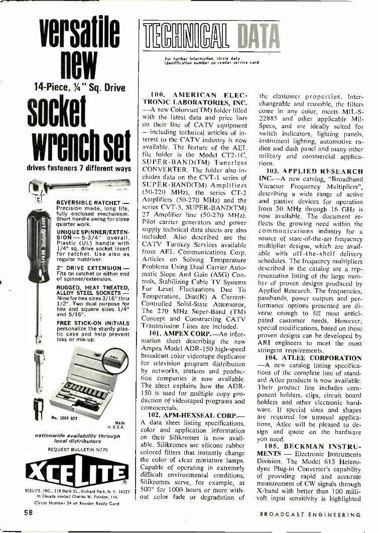
Hew14 -Piece, 1/4" Sq. Drive
socket
wrench setdrives fasteners 7 different ways
REVERSIBLE RATCHET -Precision made, long life,fully enclosed mechanism.Short handle swing for closequarter work.UNIQUE SPINNER/EXTEN-SION - 5-3/4" overall.Plastic (UL) handle with1/4" sq. drive socket insertfor ratchet. Use also asregular nutdriver.2" DRIVE EXTENSION-Fits on ratchet or either endof spinner/extension.
RUGGED, HEAT TREATED,ALLOY STEEL SOCKETS-Nine for hex sizes 3/16" thru1/2". Two dual purpose forhex and square sizes 1/4"and 5/16".FREE STICK -ON INITIALSpersonalize the sturdy plas-tic case and help preventloss or mix-up.
MadeU.S.A.n
nationwide availability throughlocal distributors
REQUEST BULLETIN N770
XCELITE, INC., 118 Bank St., Orchard Park, N. Y. 14127In Canada contact Charles W. Pointon, Ltd.
Circle Number 34 on Reader Reply Card
C-7
MEM DATAFor further Information, circle dataidentification number on reader service card
100. AMERICAN ELEC-TRONIC LABORATORIES, INC.-A new Colorvue(TM) folder filledwith the latest data and price listson their line of CATV equipment-including technical articles of in-terest to the CATV industry is nowavailable. The feature of the AELfile folder is the Model CT2-1C,SUPER-BAND(TM) TunerlessCONVERTER. The folder also in-cludes data on the CVT-1 series ofSUPER-BAND(TM) Amplifiers(50-220 MHz), the series CT -2Amplifiers (50-270 MHz) and theseries CVT-3, SUPER-BAND(TM)27 Amplifier line (50-270 MHz).Pilot carrier generators and powersupply technical data sheets are alsoincluded. Also described are theCATV Turnkey Services availablefrom AEL Communications Corp.Articles on Solving TemperatureProblems Using Dual Carrier Auto-matic Slope And Gain (ASG) Con-trols, Stabilizing Cable TV SystemsFor Level Fluctuations Due ToTemperature, Diat(R) A Current-Controlled Solid -State Attenuator,The 270 MHz Super -Band (TM)Concept and Constructing CATVTransmission Lines are included.
101. AMPEX CORP.-An infor-mation sheet describing the newAmpex Model ADR-150 high-speedbroadcast color videotape duplicatorfor television program distributionby networks, stations and produc-tion companies is now available.The sheet explains how the ADR-150 is used for multiple copy pro-duction of videotaped programs andcommercials.
102. APM-HEXSEAL CORP.-A data sheet listing specifications,color and application informationon their Silikromes is now avail-able. Silikromes are silicone rubbercolored filters that instantly changethe color of clear miniature lamps.Capable of operating in extremelydifficult environmental conditions,Silikromes serve, for example, at500° for 1000 hours or more with-out color fade or degradation of
the elastomer properties. Inter-changeable and reusable, the filterscome in any color, meets MIL -S-22885 and other applicable Mil-Specs, and are ideally suited forswitch indicators, lighting panels,instrument lighting, automotive ra-dios and dash panel and many othermilitary and commercial applica-tions.
103. APPLIED RESEARCHINC.-A new catalog, "BroadbandVaractor Frequency Multipliers",describing a wide range of activeand passive devices for operationfrom 30 MHz through 16 GHz isnow available. The document re-flects the growing need within thecommunications industry for asource of state-of-the-art frequencymultiplier designs, which are avail-able with off -the -shelf deliveryschedules. The frequency multipliersdescribed in the catalog are a rep-resentative listing of the large num-ber of proven designs produced byApplied Research. The frequencies,passbands, power outputs and per-formance options presented are di-verse enough to fill most antici-pated customer needs. However,special modifications, based on theseproven designs can be developed byARI engineers to meet the moststringent requirements.
104. ATLEE CORPORATION-A new catalog listing specifica-tions of the complete line of stand-ard Atlee products is now available.Their product line includes com-ponent holders, clips, circuit boardholders and other electronic hard-ware. If special sizes and shapesare required for unusual applica-tions, Atlee will be pleased to de-sign and quote on the hardwareyou need.
105. BECKMAN INSTRU-MENTS - Electronic InstrumentsDivision. The Model 613 Hetero-dyne Plug-in Converter's capabilityof providing rapid and accuratemeasurement of CW signals throughX -band with better than 100 milli-volt input sensitivity is highlighted
58 BROADCAST ENGINEERING

in a new 2 -page publication nowavailable. Bulletin 2266 describesthe new Heterodyne Converter asextending the frequency capabilityof the 25-, 50-, and 100 MHz Beck-man 6100 Series Counters to coverthe range of 3.0 GHz to 12.4 GHz.The publication outlines how theModel 613 also serves as a prescalerand sensitive amplifier for signals to200 MHz. By use of a toggle switch,direct measurements to as high as136 MHz can be made with thebasic counter without unplugging the613 or disconnecting its microwaveinput. Complete specifications andprice information are also provided.
106. C. P. CLARE & CO-Small, low cost, 10 amp plug-inswitching with less wiring expensethan octal base types is featured bynew Clare general purpose GP2 andGP3 relays described in Data SheetNo. 1302. Complete specificationsinclude coil tables listing voltagesfrom 6 to 240 vac and 6 to 110vdc. Drawings illustrate seven caseand mounting styles, including casedand uncased types and relays withsolder or plug-in terminals. Draw-ings for printed circuit board typesinclude a suggested pcb layout.
107. COHU ELECTRONICS,INC.-A rack -mounted video multi-plexer that expands the capabilitiesof existing waveform oscilloscopesand video monitors is described ina new technical data sheet (6-539).Details on Model 2486-004 includephotographs, specifications and ap-plications.
108. COLUMBIA ELEC-TRONIC CABLES-An illustrateddata sheet on Dura-Colors 82 -chan-nel coaxial cable for UHF/VHFhome color television reception isnow available. This sheet describesthe advanced design of ColumbiaDura-Color RG-59/U type cable,part No. 5750. Dura-Color is 100percent sheilded, the shield consist-ing of a mylar film coated on bothsides with aluminum foil and fourstandard tinned copper drain wiresfor conductive continuity. This typeof shield is electrically more stableand is highly resistent to moisture.Dura-Color accepts standard F type59/U connectors. The low loss cap-ability and other outstanding char-acteristics are described in illus-trated form. Also included aredescriptions of two 75 -ohm Dura-Color kits, one for UHF and VHF
(Continued on Page 60)
VTRAudio Heads
Manufactured andReconditioned by TABERNationally -recognized recorderhead manufacturing andreconditioning experts.
Heads manufactured or reconditionedunder controlled laboratory corditions.
New or reconditioned heads are guaranteed tomeet, cr exceed, equipment manufacturersspecifications.
Modern precision machine shop, and sophisti-cated laboratory installations insure highestquality newly -manufactured or reconditionedheads.
Free loaner assemblies available on request.
Cost: $310.00 for four (4) new heads installed,or $100.00 for four (4) reconditioned heads.
Call orwrite: TA B E
rip MANUFACTURING ANDR ENGINEERING COMPANY
OAKLAND INTERNATIONAL AIRPORTP. O. BOX 2365 OAKLAND, CALIFORNIA 94614
Taber's sophisticated qualitycontrol test insures total fre-quency response and- uninter-rupted sound playback. Maintainthe high quality audio that yourequipment was engineered toproduce.
TABER IS THE NATIONAL
DISTRIBUTOR OF
STL TEST TAPES
PHONE: (415) 635-3832 SHIPPING ADDRESS: 2081 EDISON AVE SAN LEANDRO, CA 94577
Circle Number 35 on Reader Reply Card
MODEL 510ANALOG
FCC TYPE APPROVED
AM FREQUENCYMONITORS
MODEL 520DIGITAL
Solid state design. Proportional oven control for
excellent stability.Fits standard relay rack.
Remote metering available - Model 510
Wet/WS METRON INSTRUMENTS, INC.1051 South Platte River Drive Denver, Colo. 80223
(303) 744-1791 TELEX 04-5729
Circle Number 36 on Reader Reply Card
November, 1970 59

(Continued from page 59)
reception and the other for UHFor VHF reception.
109. ECKEL INDUSTRIES,INC.-A 4 -page illustrated bro-chure "Portable An-Eck-OicChambers" details the use of theseanechoic enclosures in noise studiesof small electronic, electrical, andmechanical equipment; calibrationof microphones; free field responsetesting of loudspeakers; determina-tion of hearing aid characteristics;and behavior studies of small ani-mals. Nine standard models aredescribed that are available withfree -field volumes ranging from a191/4" cube to a 69" cube, andwith low frequency cutoffs from150 Hz. Among the features dis-cussed are the outstanding acousti-cal performance obtained with thechambers, the versatility in use, thelong-term economy, and the quickand easy installation. Another fea-ture is the flexibility of the enclos-ures that is enhanced by the variousoptions and accessories available.These include: vibration isolators,ventilation, microphone calibration
rigs, instrumentation supports andhangers, observation windows, andanimal cage linings. Also providedare construction details and modelarchitects' specifications. In addi-tion, a chart on noise reduction isgiven as well as a partial listing ofportable An-Eck-Oic Chamberusers.
110. ENGINEERED DATAPRODUCTS INC.-A new 56 -pagedata processing accessories catalogcontaining valuable basic informa-tion on utilization, handling, instal-lation and systems applications aswell as product prices and descrip-tions is now available. Several in-novative products, new to the EDPfield, have been introduced throughthis catalog. Among them is the"Swinger"-a cabinet -free, fresh ap-proach to side pack storage thatoffers maximum disk access. An-other is their One Piece Canister,a highly inventive, highly flexibleunit that offers outstanding ease oftape reel handling and identifica-tion, yet provides maximum protec-tion and storage desity - only afraction short of bare tape reeldensity itself. Still another time and
space saving unit is the MAXI -TRAY, especially designed for usewith the new System/3 computers.
111. FAIRCHILD SEMICON-DUCTOR-An updated edition ofthe 54/75 brochure which reflectsalmost a threefold expansion in thecompany's line of 5400 and 7400TTL integrated circuits is nowavailable. The new publication, con-tains 52 -pages and describes 63off -the -shelf products in the 54/74series. Description of the circuitsinclude information about electricalcharacteristics, switching character-istics, logic diagrams, and pin con-figurations. Recommended operat-ing conditions are also indicated.The brochure is abundantly illus-trated, with 20 pages of diagramsand schematic drawings showingtest circuits and voltage waveforms.One section of the brochure is de-voted to packaging dimensions andillustrations.
112. HEWLETT PACKARD-lncreases greater than 20 dB in thesensitivity of RF and microwaveinstruments can be obtained by sig-nal averaging techniques describedin a new 20 -page Application Note.
We're a great teamIts a shame we neverget on the air
Dye Image Staircase, Flare Test, and Color Bar Slides,available in 31/411 x 4" and 35mm from D AND S CORLEY LIMITED,4800 Dundas Street West, Toronto, Ontario. 416-231-6936.
Test Slides -OBJECTIVE COLOR TELECINE ALIGNMENTCircle Number 37 on Reader Reply Card
60 BROADCAST ENGINEERING
The Note, "Signal Averaging En-hancement of RF and Pulse Meas-urements," contains detailed dia-grams of the interconnections be-tween the signal averager and sev-eral other instruments, includingspectrum analyzers, network analyz-ers, sampling oscilloscopes, andtime -domain reflectometers. Thetheory of signal averaging is ex-plained, and the concepts of cali-brated and weighted averaging areintroduced. Also explained is theuse of the variance display-a fea-ture unique to HP signal averagers-as an indication of the validityof a measurement.
113. LECTRONIC RESEARCHLABORATORIES - The 48 -pageBulletin 93 contains one of thelargest, most diversified presenta-tions of electronic test equipmentand sophisticated components. Spe-cial sections are included on: testequipment, power supplies, bridges,decades, delay lines, 400 Hz powersources, high voltage power sup-plies and hipot testers, portable in-struments, pulse networks and trans-formers, synchros and tachometergenerators, servo motors and manyothers.
114. METEX CORPORATION-A new, 28 -page short form cata-log covering EMI shielding ma-terials, gaskets and components isnow available. Covered are thecompany's Polastrip and Pola-Hcomposite EMI and pressure gas-keting, EMI Mesh Strips, Metalex,EMI gasketing, Xecon conductingelastometer, connector gaskets,Shield Vu EMI shielded windows,Shield Cell EMI shielded ventilat-ing panels, Shield -screen EMIshielded air filters, ZIPEX-2 EMIcable shielding and other productsmanufactured by Metex. The cata-log is fully illustrated and unusuallycomplete, containing all necessaryordering information, full specifica-tions and extensive part numbertabulations.
115. PHELPS DODGE COM-MUNICATIONS CO.-A new 68 -page catalog completely coveringthe company's full line of antennasystems is now available. In addi-tion to the illustration of each typeof antenna, along with specifica-tions and performance data, thenew catalog also includes descrip-tive material on antenna mountinghardware, duplexers and cavity res-
onators, coaxial cable systems andantenna mounting accessories. Aspecial technical data section is in-corporated offering information de-signed to be of assistance to thecommunications specialist.
116. MICROWWAVE SEMI-CONDUCTOR DIVISION - Anew brochure entitled "Noise Engi-neering Data" is now available.Ideal for reference and specifica-tion, the 6 -page brochure describesDesirable Noise in terms whichpermit the engineer to analyze hisneeds and make best use of thedata presented. The brochure indi-cates several applications in theelectronics industry in which noiseis desirable rather than an enemy,i.e., as the carrier for secure com-munications, as a jamming signal,as a reference signal level for built-in test equipment and as an ampli-tude reference for determining re-ceiver noise figure. In addition, thebrochure explains how to purchasenoise, as raw diodes, in modulesor in systems. Each package hasits own set of specifications, bene-fits and requirements. For example,the raw diode must be packagedinto a compatible structure by thedesign engineer, the module needonly be coupled to and the systemhas an output jack and an ON -OFFswitch. Examples of each areillustrated.
117. RCA ELECTRONIC COM-PONENTS-A new booklet, "RCASilicon Rectifiers, Assemblies, andBridges" Publication No. SRS -300Ais now available. The booklet con-tains characteristics charts for theentire rectifier product line, a briefintroduction, and a statement ofRCA's custom -design capability inthe field of "stacks" and bridges.The RCA line of diffused -junctionsilicon rectifiers includes more than150 devices, ranging from 1 mA,200 V units for consumer and low -voltage industrial applications tohigh -voltage rectifier assemblies.The booklet also features a "De-signers' Guide for Rectifier Cir-cuits." This double -page chartwhich includes a sample calcula-tion, enables the engineer to deter-mine voltage ratings for high -volt-age assemblies required for a par-ticular circuit configuration.
Send Your Industry NewsTo Broadcast Engineering
UNLIMITEDVARIETY
INCOMPARABLEQUALITY
SWITCHCRAFTPHONE PLUGS
Why waste time "shopping around". . . whatever your plug requirement-regardless of size or type, Switchcraftmakes it, and makes it better! Theone piece tip rod, for instance, isstaked into the terminal to assuretightness ... the tip rod can't fall out!Switchcraft offers you the world's lar-gest selection of phone plugs ... withsolder terminals, screw terminals, ca-ble clamps; .250", .206", .140", .097"finger diameters; shielded handles, ortough plastic handles; single plugs,twin -plugs; 2 -conductor or 3 -conductor-you name it! Chances are it's athoroughly proved, field-tested STOCKplug from the incomparable Switch -craft line of plugs.SEND FOR NEW CATALOG P-202or see your Switchcraft Authorized In-dustrial Distributor for immediate de-livery at factory prices.
syxI-V-1061.15535 No. Elston Ave.
Chicago, Illinois 60630Canada: Atlas Radio Corp., LTD.
50 Wingold Ave., Toronto, Canada
November, 1970Circle Number 38 on Reader Reply Card
61

THE ONLY CIRCULARIZED
FM ANTENNAWITH VARIABLE HORIZONTAL - TO -
VERTICAL GAIN RATIOS!
JAMPRO'S new PENETRATOR FM an-tenna allows you to reach everylistener in your signal area . . .
even on the fringes. Penetratesmore auto sets, and small port.ables, too.What's the secret? JAMPRO'S NEW
PATENTED DESIGN offers you truecircular polarization (not just amodified ring), and a greater VSWRband width for better stereo andSCA operation.
EXCLUSIVE FIELD TRIMMING STUBSguarantee lower VSWR -on yourtower, where it counts - of 1.08to 1 (that's the lowest in theindustry). Incidentally, so are ourprices!
CALL US NOW!
LET'S TRADE ANTENNAS
(916) 383.1177
ANTENNA COMPANYA DIVISION OF COMPUTER EQUIPMENT CORP
6939 Power Inn RoadSacramento, California 95828
Second Series FCCReports Now Available
Volume 16 of the Second Seriesof FCC Reports, covering the periodof February 7, 1969 to April 4,1969, is now available to the public.The 1,140 page book (cataloguenumber 1970 0 -LT -351-460) isavailable from the Superintendent ofDocuments, U.S. Government Print-ing Office, Washington, D.C. 20402,for $6.
In addition to decisions, reports,memorandum opinions, orders, andother selected material the volumecontains a digest of statutory andrule provisions and a digest by sub-ject. It also permits reference bycall letters and localities, as well asthrough documents reported.
The complete FCC Reports nowconsist of a First Series of 40 boundvolumes, dating from July 17, 1934to July 9, 1965, and the SecondSeries of 16 volumes covering theperiod July 9, 1965 to April 4,1969. Volume 41 (Television Mat-ters) of the First Series, includingCommission documents and actionsup to July 1, 1965, is currentlyunder preparation by the Govern-ment Printing Office.
ITIM1111° INDEXBelar Elect onic Laboratory Inc. 55Broadcast Electronics 16, 52, 56CCA Electronics Corp. 8Cohu Electronics. Inc. 1Collins Radio 21Cunningham Corp. 11Crown International 49
D & S Corley Ltd. 60The Denson Electronic Corp. 48
Electro-Voice, Inc. Cover 2Fairchild Sound Equip. Corp. 10
Gates Radio Company 5The Grass Valley Group, Inc. 3
International Nuclear Corp. Cover 3Jampro Antenna Co. 62Joa Cartridge 56
Liberty Industries 62Lipsner-Smith Corp. 43
3M Company 51Metron Instruments, Inc. 59Mincom Div. 3M Company 19Moseley Associates, Inc. 52Minneapolis Magnetics, Inc. 49
Rupert Neve & Co. LTD. 47North American Philips Corp. 39
Phelps Dodge Communications Co. 7Philips Broadcast Equipment Corp. 25
QRK/Rek-O-Kut 12Quick -Set Inc. 50
Recortec, Inc. 57Russco Electronics Mfg. Co. 54
Spotmaster 16, 52, 56Stainless Inc. 15Stanton Magnetics, Inc. 9Superscope, Inc. 17Switchcraft 61Sylvania Electric Products, Inc. 45
Taber Manufacturing & Eng. Co. 59Tapathon Corp. 41Teac Corporation Of America Cover 4Tele Mation, Inc. 13Telex Communication Div. 63Thomson SCF 31
Visual Electronics Corp. 14
Xcelite, Inc. 58
ELIMINATE AIRBORNE DUSTPROBLEMS ON VTR EQUIPMENT
New ISOLAIR Unit by LibertyThis unit provides a laminardownflow of the cleanest possi-ble air at the critical video headarea. Excessive wear and dam-age by airborne contaminantsare virtually eliminated, extend.ing head life by 100% or moreand insuring better overall VTRperformance. The elimination ofthis dust problem by use of theIsolair results in great savingsof time and money.Also, the surrounding area inwhich an Isolair unit is operat-ing benefits by a progressively
4.010 reduced level of airborne partic-ulate matter.
4N Chief engineers who have usedthe Isolair unit have attestedto the multiple advantages pro-vided by this low-cost VTRaccessory.
Meets Federal Standard 209a, Class 100. Easily installed and maintained. Requires no additional floor space. Eliminates need for any other dust control equipment.
LIBERTY
FOR FURTHER INFORMATION CALL OR WRITE
LIBERTY INDUSTRIES, INC.598 Deming Road, Berlin, Conn. 06037
Telephone (203) 828-6361Circle Number 29 on Reader Reply Card
BROADCAST ENGINEERINGCircle Number 39 on Reader Reply Card
62

FCC Equipment ListInterconnect Data Ready
The latest listing of Radio Equipment Acceptablefor Licensing, dated July 31, 1970, has been issuedby the Federal Communications Commission.
The list includes equipment for the Domestic PublicRadio Services other than Maritime Mobile; RadioBroadcast Services; Experimental, Auxiliary and SpecialBroadcast Services; Stations on Land in MaritimeServices; Stations on Shipboard in Maritime Services;Public Fixed Stations and Stations in the MaritimeServices in Alaska; Aviation Services; Public SafetyRadio Services; Industrial Radio Services; Land Trans-portation Radio Services; and Citizens Radio Service.
The transmitters listed are considered acceptable forlicensing in the various services provided that theiroperation is in accordance with Commission rules andthe specifications for this equipment are not exceeded.The list also includes frequency and modulation moni-tors that are type approved for use in the radio broad-cast service. Equipment is listed alphabetically by man-ufacturer and numerically by type number.
Inquiries about equipment listing may be addressedto Technical Division, Technical Standards Branch,Federal communications Commission, Washington,D.C. 20554 (Telephone 632-7093, area code 202).
The report entitled "Interconnection Action Recom-mendations" prepared by Dittberner Associates relat-ing to attachment of consumer -provided equipment tothe Nation's telephone networks, announced by theCommission on September 1, 1970, will be availablefor sale to the public through the United States De-partment of Commerce.
The report will be sold for $3 per copy; microfichecopies of the report will also be available at $.65 percopy. Orders should be addressed to the United StatesDepartment of Commerce, National Technical Infor-mation Service (formerly Clearinghouse for FederalScientific and Technical Information), Springfield,Virginia 22151. The accession number for the reportis PB 193 636 and should be included with all orders.
Irwin S. Elyn, an attorney -adviser in the BroadcastBureau's Renewal and Transfer Division, has beenappointed Chief of the Transfer Branch.
New Transfer Div. ChiefA native of Seattle, Washington, Elyn received
his law degree from the University of Washington andwas in private practice in Seattle before joining theCommission in 1963. He served as a trial attorney withthe Hearing Division and as an attorney -adviser inthe Renewal and Transfer Division from 1963 to 1967before moving to the Office of the General Counselfor an assignment with the Administrative Law andTreaties Division. He returned to the Renewal andTransfer Division at the end of 1968.
The Transfer Branch is responsible for processingall applications for assignments of licenses.
Telex writesnew specson sensitivityand ruggednessin headphones.
Communications Series 1320HIGH SENSITIVITY AND LOW OPERATINGPOWER. The new Communications Series1320 headphones are designed around adramatic new driver that requires only abso-lute minimal operating power. This addedefficiency allows fora substantial increase insensitivity without any increase in distortion,making the 1320 Series the most sensitiveand versatile headphones available today.
RUGGED. CONSISTENT PERFORMANCE. Un-like the soft aluminum or paper cones inmost of today's headphones, the 1320'srugged new cone is made of special materialthat will provide peak performance withoutbe4ig affected by temperature or humidity.This means that you get consistent, highquality performance, day in and day out,under the most demanding communicationsconditions.
For more information on Telex's new Series1320 headphones, contact your nearest Telexdealer or write.
anoDuc,s DF SOL,40
TELEX®COMMoN$C.S7tONS OtV,9,13N9600 Aldrich Avenue SouthMinneapolis, Minnesota 55420
November, 1970
Circle Number 40 on Reader Repfy Card
63

PROFESSIONAL Equipment for Sale Help Wanted
VIR JAMESCONSULTING RADIO ENGINEERSApplications and Field Engineering
345 Colorado Blvd.Phone: (Area Code 303) 333-5562
DENVER, COLORADO 80206Member AFCCE
TWX 910-931-0514
AMPEX SERVICE COMPANYA Department Of Ampex Corporation
500 Rodier Drive, Glendale, California 91201(213) 245-9373
Service center for repair, modification, re-building of all Ampex helical -scan video re-corders and associated equipment. Also the
complete Ampex au-AMPEX dio line.
WALTER F. KEANCONSULTING RADIO ENGINEERS
19 E. Quincy StreetRiverside, Illinois 60546
(A Chicago Suburb)
Phone 312-447.2401Member AFCCE
COMMERCIAL RADIOMONITORING CO.PRECISION FREQUENCY
MEASUREMENTS
AM -FM -TV
103 S. Market St., Lee's Summit, Mo.Phone Kansas City, Laclede 4-3777
Associated Communications ConsultantsWALTER J. STILES
Suite 1621, Tucson HouseTucson, Arizona 85705
(602) 792-2108
LUKE 0. HODGESDallas, Texas
(214) 351-3820
CAMBRIDGE CRYSTALSPRECISION FREQUENCY
MEASURING SERVICESPECIALISTS FOR AM -FM -TV
445 Concord Ave. Phone 876-2810
Cambridge, Mass. 02138
ALLSTATE COMMUNICATIONSENGINEERS - CONTRACTORS
CAN -CCTV -VTR1200 WEST CHESTNUT STREET
UNION, NEW JERSEY 07083(212) 349-5240
Advertising rates in C ass fled Section are154 per word, each insertion, and must be ac-companied by cash to Insure publication.
Each initial or abbreviation counts a fullword. Upper case words, 300 each.
Minimum classified charge, $2.00.For ads on which replies are sent to us for
forwarding, there is an additional charge of$2.00 to cover department number, etc., whichis printed in advertising copy, and processingof replies.
Classified columns are not open to adver-tising of any products regularly produced bymanufacturers unless used and no longerowned by the manufacturer or a distributor.
CARTRIDGE TAPE EQUIPMENT-Com-pletely reconditioned Sp otm aster andTapecaster Record/Play back s, $375.00.Playbacks $250.00. 30 -day money -backguarantee on all equipment. BROADCASTPRODUCTS CO., INC. 12330 Wilkins Ave-nue, Rockville, Maryland 20852. Ph: 301-933-3400, 10-69-tf
Surplus audio and video patch panels andpatch cords. 500 to 500 ohm repeat coilsflat to 20,000 cycles. Send for list. GulfElectro-Sales, Inc., 6325 Beverly Hill,Houston, Texas 77027. 9-70-tf
RIGID TRANSMISSION LINE - 6 Va'-50ohm, 20' lgths, flanged, Andrews 573, un-used. 500 Ft available. Bargain. SierraWestern Electric, Box 23872, Oakland,California 94615. (415) 832-3527. 8-70-tf
Finest RF coils, contactors, switches, cus-tom ATU systems built for customers ordealers. Write or phone for catalogue.Geleco Electronics Ltd.. 2 ThorncliffePark Drive, Toronto 17, Ontario. Phone416-421-5631. 8-70-tf
CBS Audimax III 44, $400 . . .HewlettPackard 335B FM monitor, $325 . . . RustSFM-19 Pilot Freq Mon, $200 . . . GEBA -5B limiter $50 . . . RCA WM-43AMmonitor $50. Mat Rubin. KMPX-FM, 415-771-8505. 11-70-1t
TEKTRONIX 524-D OSCILLOSCOPE,with mobile cart. Good condition. $495.Richie, 643 Diamond Rd., Salem, Virginia24153. 11-70-1t
AMPEX spare parts, technical support,updating kits, for discontinued profes-sional audio models, available from VIFINTERNATIONAL, Box 1555, Mtn. View,Ca. 94040. (408) 739-9740. 9 -70 -EOM
FOR SALE: TK-26B color film chain lessprojectors and multiplexer $5,000.00 FOBplus crate and ship. Palmer 16MM B/Winescope system model VFR-2S $8,500.00FOB plus crate and ship. Broadcast En-gineering, Box 242, 1014 Wyandotte, St.,Kansas City, Mo. 64105. 11 -70 -it
Services
CUSTOM CARTRIDGE RELOADING, andrefurbishing. Fidelipac replacement partsand cartridges. Write us today for prices.PROFESSIONAL AUDIO SERVICES,BOX 1953, FORT WORTH, TEXAS 76101.
6 -70 -fit
CRYSTAL & MONITOR SERVICE, Fre-quency change, repair or replacement ofoven type broadcast crystals. Also fre-quency change and recalibration or repairof AM frequency monitors, and H -P FMmonitors. Fast service at reasonableprices, 30 years experience! Call or write:Eidson Electronic Co. Box 96, Temple,Tx. 76501. Pho. 817 773-3901. 9-70-12t
Southeastern AM -FM -TV Station offersabove average salaries for engineers ex-perienced in AM -FM -TV Operation andmaintenance. First Class License neces-sary. First Class Engineers without ex-perience will be considered. Reply mustbe complete with references, photographand salary requirements. Reply Dept. 241,1014 Wyandotte Street. Kansas City, Mis-souri 64105. 10-70-4t
Immediate full-time opening for videotechnician to service black -and -white andcolor closed-circuit television equipment.This television complex is one of the mostsophisticated in New England. Send sal-ary requirements and resume to: RichardD. Walsh, Director of Engineering, GrahmJunior College, 632 Beacon Street, Bos-ton, Massachusetts 02215. 11-70-1t
Job Headquarters for all Radio and Tele-vision Engineers. Immediate openings ex-ist in 9 western states and elsewhere forqualified engineer and technical person-nel. All categories from trainees to ex-perienced transmitter maintenance. chief.assistant chief, live color video mainte-nance and technical operations. Send usyour complete resume now. TJie AMPSAgency, 3924 Wilshire Blvd., Los Ange-les. California 90005. Telephone DU 8-3116. By Broadcasters-For Broadcasters.
11-68-tf
SENIOR TELEVISION ENGINEER. Musthave strong maintenance background withthe latest solid state broadcast color tele-vision equipment. Send resume to: RonaldT. Lask, Chief Broadcasting Engineer,Television Section, University of Illinois,Medical Center. PO Box 6998, Chicago,Illinois 60680. 9-70-3t
Training
To advance in electronics, knowledge andability are required. Grantham offerscorrespondence and resident instruction,in depth, leading to the degree of Asso-ciate in Science in Electronics Engineer-ing. G. I. Bill approved. Credit for pre-vious training and experience allowed.Free Catalog. Write: Dept. E-2, GranthamSchool of Electronics. 1505 N. WesternAve., Hollywood. California 90027, 6-67-tf
First phone through tape recorded lessonsat home plus one week personal instruc-tion in Washington. DC. Atlanta. Boston.Detroit. New Orleans, Minneapolis, Se-attle, Denver. Portland. Los Angeles.Proven results. Our 17th year teachingFCC license courses. Bob Johnson RadioLicense Preparation, 1060D Duncan, Man-hattan Beach. Calif. 80266. Phone 213-379-4461. 1-69-tf
IMMEDIATE OPENINGS: Qualify for anyof the following positions: RCA CCTVEquipment, monochrome or color. Sales-men - TV Systems Engineers - ProjectEngineers - Supervisors - Managers -Maintenance Technicians - Video Engi-neers - to work either New York. Penn-sylvania. New Jersey or California area.Write: RCA Rep., P. 0 Box 268, NewHyde Park. New York 11040. 4-70-tf
First Phone Available Now. AM -FM Ex-perienced. Hi -Lo Powers. Franz A. Smith,2604 Gilmore Ct., Topeka, Ks. CE 3-9396.
11-70-1t
Send your Engineer'sExchange Ideas To:
BE, 1014 WyandotteKansas City, Mo. 64105
"1/f> av7C7, A wH,47- pee.s- 'ccry' 4,7,4//
64 BROADCAST ENGINEERING

Why Compromise?Customize...
with I.N.C.'S SCR Solid State Control and Video "REED CROSSBAR" Switchers
TBC2 Solid StateBackground Colorise,
TSC2 Solid StateSync Comparator
TPC2 Solid StateBurst Phase Corrector
TMA2 Solid StateMixer Amplifier
EMI
ERECTS
MOM
AUIRIAA1
PAOGAIM
MIX A
I
22 COMPOSITE OR NON COMPOSITE INPUTS V
BLACK 1 2 3 4 5<-tbrf-c 18 18
rbb,7;;7R4 V
A
EMUSreleIllerr
- owIlur
TAM Solid StateAudio Pogrom Amplifier
TDA2D Solid State Video/Pulse Distribution Amplifier
with Sync Add
8 X 5 AUTOMATIC CROSSBAR
0 INDICATES SLAVE CIRCUIT OPERATED BY 22 X 7 SWITCHES
International Nuclear Corporation developed the firstSolid -State Transistorized Video Distribution Amplifierfor the television broadcast industry. Hundreds of theseunits are still in operation today. I.N.C. has also designedand manufactured complete video switching systems forthe major television networks and broadcast stations.We can design and manufacture your complete switchingsystem to meet your exact requirements.I.N.C. sets no limit on Input -Output busses. A singleswitching cross -bar can be operated from any number ofstudios, master controls or VTR positions. Vertical intervalswitching, single re-entry, dual re-entry, keying busses,
KU
l+11"At
4. TPA1 Solid State Audio Monitor Amplifier
4.I
4.I..
TBG2 Solid State ColorBlack Burst Generator
TCS2 Solid State- Sul:Kerrie, Standard
7'7'77'77t>
I
1
MRI
mnn
I
L _ _ _ uLwl
lap -dissolve busses, special effects busses, preview busses,audio -follow -video, audio -not -follow -video, cut -bars, presetand transfer switching and even computer -operatingswitching is available for the asking.I.N.C.'s video switching systems are designed to meet themost stringent demands for broadcast color reproductionand for the ultimate in reliability. I.N.C. uses SCR Solid -State control circuitry, video "Reed Relay Crosspoints"hermetically sealed in an inert atmosphere for videoswitching, and reed relay or solid-state audio switching.For technical data, engineering assistance, and budgetarypricing, call I.N.C. 615 - 254-3365. We are as near asyour telephone.
INTERNATIONAL NUCLEAR CORPORATION608 Norris Avenue Nashville, Tennessee 37204 Phone 615 - 254-3365
Manufacturers of Video Broadcast Auxiliary EquipmentCircle Number 2 on Reader Reply Card

When you know what it takes to make a TEAC, you know why professional peoplewax lyrical about our A-7030.
This is a no-nonsense pro -quality tape deck, with unrivalled sound reproduction at 15 or71/2 ips. A.streamlined solenoid control system for effortless operation. A system that makescueing as easy as pushing a button. Automatic rewind and shutoff for built-in convenience.
The A-7030 is the sum of many systems, and the sum of our savvy in producing them.It's the head of our whole fine family of tape decks.
So if somebody wants to write a sonnet on it, we've got a great line for them. Nu,.
TEACSOUNDS LIKEPOETRY TOTHE PROS.
A-7030 Dual -speed hysteresis -synchronous
motor for capstan drive Two heavy duty 6 -pole capacitor -start
induction motors for reel drive Tape tension adjustment Massive inertial flywheel, over 11/2 pounds Instant off -the -tape monitoring withoutinterruption of recording
Sound -on -sound and echo with simpleexternal connections
Built-in mike -line mixer Stainless steel panel reinforced with
13/64" aluminum base plate for assuredstable performance
TEACTEAC Corporation of America2000 Colorado AvenueSanta Monica, California 90404
Circle Number 3 on Reader Reply Card