Embed Size (px)
Citation preview
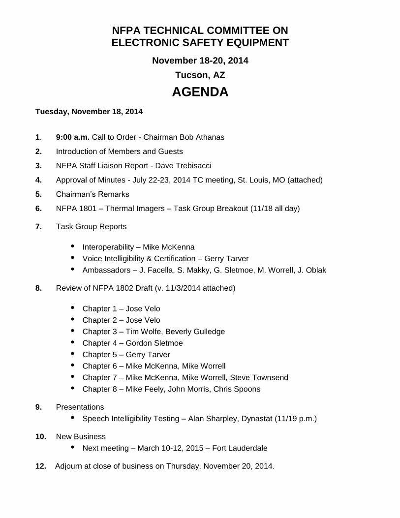
NFPA TECHNICAL COMMITTEE ON ELECTRONIC SAFETY EQUIPMENT
November 18-20, 2014
Tucson, AZ
AGENDA
Tuesday, November 18, 2014
1. 9:00 a.m. Call to Order - Chairman Bob Athanas
2. Introduction of Members and Guests
3. NFPA Staff Liaison Report - Dave Trebisacci
4. Approval of Minutes - July 22-23, 2014 TC meeting, St. Louis, MO (attached)
5. Chairman’s Remarks
6. NFPA 1801 – Thermal Imagers – Task Group Breakout (11/18 all day)
7. Task Group Reports
• Interoperability – Mike McKenna
• Voice Intelligibility & Certification – Gerry Tarver
• Ambassadors – J. Facella, S. Makky, G. Sletmoe, M. Worrell, J. Oblak 8. Review of NFPA 1802 Draft (v. 11/3/2014 attached)
• Chapter 1 – Jose Velo
• Chapter 2 – Jose Velo
• Chapter 3 – Tim Wolfe, Beverly Gulledge
• Chapter 4 – Gordon Sletmoe
• Chapter 5 – Gerry Tarver
• Chapter 6 – Mike McKenna, Mike Worrell
• Chapter 7 – Mike McKenna, Mike Worrell, Steve Townsend
• Chapter 8 – Mike Feely, John Morris, Chris Spoons 9. Presentations
• Speech Intelligibility Testing – Alan Sharpley, Dynastat (11/19 p.m.) 10. New Business
• Next meeting – March 10-12, 2015 – Fort Lauderdale
12. Adjourn at close of business on Thursday, November 20, 2014.
1
Technical Committee on Electronic Safety Equipment Minutes of the Meeting
July 22-23, 2014
St. Louis, MO
Agenda Items #1-3: Call to Order, Introduction of Members and Guests, and Committee Procedures Chairman Athanas called the Committee to order at 9 a.m. on July 22, 2014. Chairman Athanas welcomed Committee members and guests and asked them to introduce themselves. David Trebisacci provided the staff liaison report and asked attendees to sign in on the appropriate Member or Guest sign-in sheet. Members present:
Robert Athanas, Chairman FDNY/SAFE-IR, Inc. Chris Spoons, Secretary David Trebisacci, Staff Liaison NFPA Kamil Agi K&A Wireless, LLC Jason Allen Intertek Testing Services Joel Berger Kenwood USA Corporation Matt Bowyer NIOSH Matthew Busa Motorola Solutions John Facella RCC Consultants William Forsyth USDA Forest Service Craig Gestler MSA Wayne Haase Summit Safety, Inc. Zachary Haase Summit Safety, Inc. Simon Hogg Draeger Safety Michael Hussey Jackson County Fire District 3 John Jarboe Grace Industries, Inc. Paul Kelly Underwriters Laboratories Inc. Steven Makky APCO International Inc. Brian Martens Harris Corporation Michael McKenna Michael McKenna & Associates, LLC John Morris ISG Infrasys Timothy Rehak NIOSH James Rose Safety Equipment Institute Matthew Shannon Scott Safety Christina Spoons Westmont Fire Department Gerry Tarver Tulsa Fire Department Steven Townsend Carrollton Fire Rescue Jose L. Velo San Francisco Fire Department Gregory Vrablik Honeywell Safety Products (representing ISEA) Mike Worrell Phoenix Fire Department
2
Guests present: Michelle Donnelly NIST Sandy Florence Motorola Solutions Beverly Gulledge Scott Safety Jeff Helvin IAFF Tim Houston Motorola Solutions Michael Jenks Tait John Oblak EF Johnson John Rehayem Otto Engineering Gordon Sletmoe Lebanon Fire District William Young NIST
Agenda Item #4: Approval of the Minutes of the March 2014 meeting in Ft. Lauderdale, FL. The committee reviewed the minutes of the meeting held March 18-19 in Ft. Lauderdale, FL. No changes were proposed.
Motion to accept the minutes: Mike McKenna Second: Jack Jarboe
To approve the Minutes of the March 18-19 meeting
Motion carried
Agenda Items #5: Chairman’s Remarks Chairman Athanas welcomed all members and guests to St. Louis. He then updated the committee on the progress of the NFPA 1802 document and reminded the group that we will need to split time at the next meeting between NFPA 1802 and NFPA 1801. Agenda Item #6: Task Group Reports The following members of the Ambassador task group provided updates on their outreach efforts: John Facella – NFPA 1221 and other media groups Mike Worrell – First Net Steve Makky – APCO, NPSTIC John Oblak – TIA meetings
Steve Townsend – IAB
Feature set task group: Mike Worrell provided an update on programmable features Hazardous Location task group: Steve Townsend and Paul Kelly provided an update
3
RF PASS: Gordon Sletmoe provided an update. Physical properties: Mike McKenna provided an update. Voice intelligibility and certification: Gerry Tarver provided an update. Chairman Athanas assigned a task group on Design Requirements:
Bill Forsyth Jason Allen Michelle Donnelly Tim Houston Steve Makky Jose Velo Matt Bowyer Steve Townsend Gerry Tarver
Agenda Item #7: Presentations John Oblak reported on his work with TIA regarding NFPA 1802. He made a formal presentation to the TC on TIA transceiver standards. He recommended adoption by reference of appropriate TIA standards or subsets of those standards into NFPA 1802 (see Attachment 1). Bill Young reported on tests from TIA standards that could possibly be included in NFPA 1802, the limitations associated with those tests, and what test modifications should be considered from an environmental standpoint (see Attachment 2). Related to Bill’s presentation, the TC had considerable discussion about potential power level requirements. Michelle Donnelly and Bill Young reported on testing LMRs at elevated temperatures (see Attachments 3 and 4). All radios tested experienced frequency drift above 5 ppm or cessation of operation during testing specified within the four classes defined by NIST. The TC discussed at length the issues associated with such drift. NIST will continue to do elevated temperature testing and perhaps include the receiving radio in such tests (they have only tested the transmitting radio thus far). Steve Makky gave a presentation on the NPSTC PAM tool, a cross-manufacturer interoperable parameter criteria tool (see Attachment 5). It is also available at http://npstc.org. Paul Kelly gave a task group report on hazardous locations (see Attachment 6).
4
Agenda Item #8: Review of NFPA 1802 Draft The committee began reviewing the draft to date of NFPA 1802. Chairman Athanas assigned responsibility for each chapter of the document. Some of these correspond to task groups that have already been formed. Some groups have now been assigned co-chairs in case someone isn’t able to attend a TC meeting. Emails for the chair/co-chairs are included below. [NOTE: TG input to be provided to Bob Athanas and Dave Trebisacci by October 24, 2014]. Chapters 1 and 2: Jose Velo ([email protected]) Chapter 3: Tim Wolf ([email protected]) is the task group chair for the task group corresponding to this chapter. Beverly Gulledge ([email protected]) has been added as co-chair of this group. Chapter 4: Gordon Sletmoe ([email protected]) will work with Jim Rose and Steve Weinstein. Chapter 5: Gerry Tarver ([email protected]) with Steve Weinstein and Craig Gestler Chapter 6: Mike McKenna ([email protected]) and Mike Worrell Chapter 7: Mike McKenna ([email protected]), Mike Worrell, and Steve Townsend Chapter 8: Mike Feely ([email protected]) is the task group chair for the task group corresponding to this chapter. Chris Spoons ([email protected]) has been added as co-chair. Agenda Item #9: New Business The next meeting is scheduled for November 18-20, 2014, in Tucson, AZ. Future meetings are planned for the weeks of March 9, 2015 (Fort Lauderdale) and July 20 (west), and in October (mid-west). Agenda Item #10: Adjourn at close of business Having no further business, Chairman Athanas sought a motion to adjourn the meeting.
Motion: Tim Rehak Second: Jose Velo
To adjourn the meeting
Motion passed
Chairman Athanas adjourned the meeting at 4:30 p.m. Respectfully submitted, Chris Spoons, Secretary TC on Electronic Safety Equipment
8/14/2014
1
John Oblak – Chair TIA TR 8 and TR 8.1July 22, 2014
1
TIA Transceiver StandardsAnalog Radio
TIA 603 D – Measurement Methods and PerformanceRecommendations
Project 25 Phase ITIA 102.CAAA D – Measurement MethodsTIA 102.CAAB D – Performance Recommendations
Project 25 Phase II (TDMA)TIA 102.CCAA A – Measurement MethodsTIA 102.CCAB A – Performance Recommendations
2
Why use TIA StandardsLand Mobile Radio is a mature industry
TIA Standards used for many years assess radio performanceStandards are mature
Some standards have been published for over 20 yearsDeveloped from earlier standards documentsANSI Accredited
TIA Transceiver Standards are ComprehensiveTest equipment manufacturers have developed test equipment toimplement TIA testing
Almost all of the TIA measurement methods have been supportedby test equipment manufacturers
Agilent, Tektronix, Rohde and Schwarz, Aeroflex, Anritsu, etc.Test equipment manufacturers have assisted in developing the teststandards
Corresponds to the radio systems being used3
8/14/2014
2
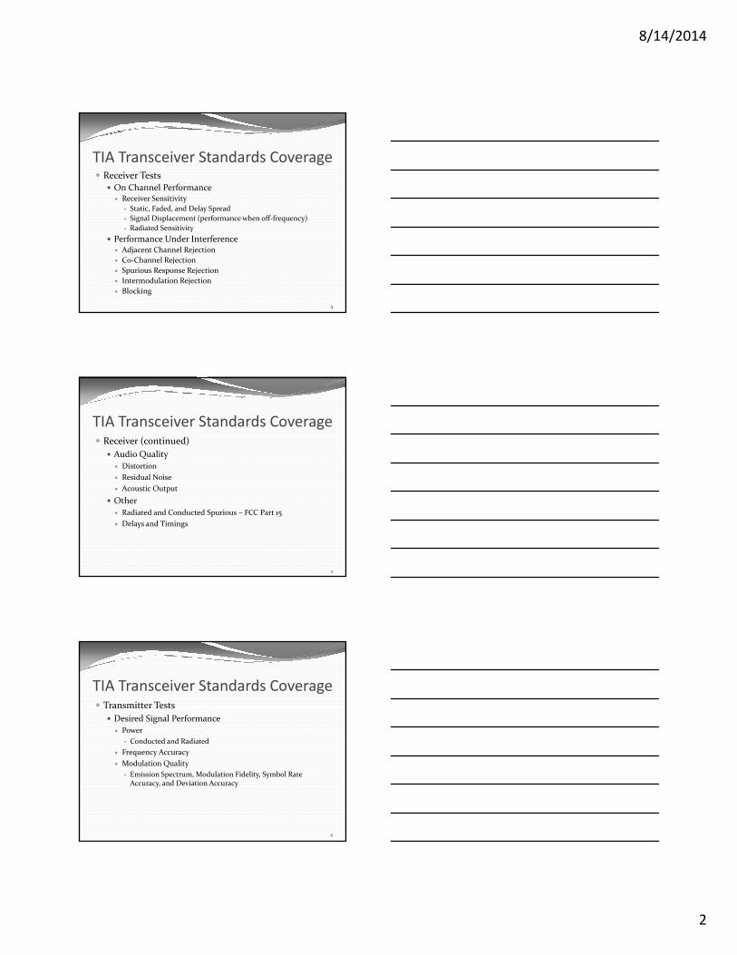
TIA Transceiver Standards CoverageReceiver Tests
On Channel PerformanceReceiver Sensitivity
Static, Faded, and Delay SpreadSignal Displacement (performance when off frequency)Radiated Sensitivity
Performance Under InterferenceAdjacent Channel RejectionCo Channel RejectionSpurious Response RejectionIntermodulation RejectionBlocking
4
TIA Transceiver Standards CoverageReceiver (continued)
Audio QualityDistortionResidual NoiseAcoustic Output
OtherRadiated and Conducted Spurious – FCC Part 15Delays and Timings
5
TIA Transceiver Standards CoverageTransmitter Tests
Desired Signal PerformancePower
Conducted and RadiatedFrequency AccuracyModulation Quality
Emission Spectrum, Modulation Fidelity, Symbol RateAccuracy, and Deviation Accuracy
6
8/14/2014
3
TIA Transceiver Standards CoverageTransmitter (continued)
Interference ProtectionConducted and Radiated SpuriousAdjacent Channel PowerStability into VSWRTransient Frequency Behavior
Acoustic PerformanceAcoustic SensitivityDistortion, Hum and Noise
OtherDelays and Timings
7
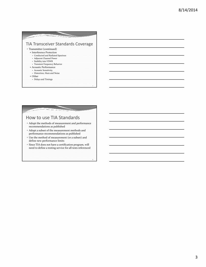
How to use TIA StandardsAdopt the methods of measurement and performancerecommendations as publishedAdopt a subset of the measurement methods andperformance recommendations as publishedUse the method of measurement (or a subset) anddefine new performance limitsSince TIA does not have a certification program, willneed to define a testing service for all tests referenced
8
8/14/2014
1
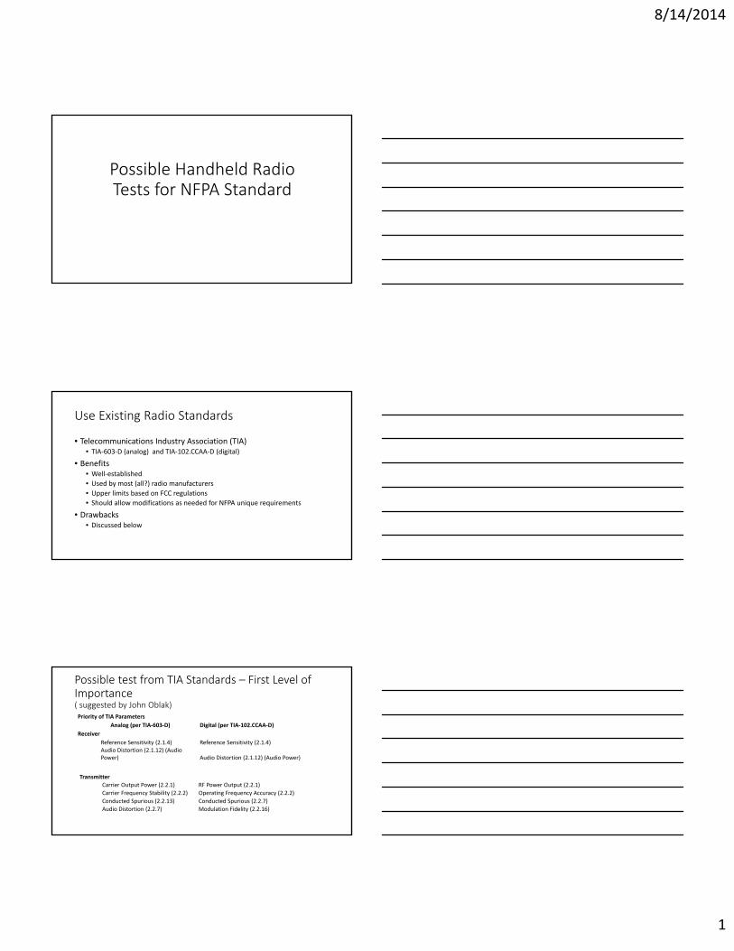
Possible Handheld RadioTests for NFPA Standard
Use Existing Radio Standards
• Telecommunications Industry Association (TIA)• TIA 603 D (analog) and TIA 102.CCAA D (digital)
• Benefits• Well established• Used by most (all?) radio manufacturers• Upper limits based on FCC regulations• Should allow modifications as needed for NFPA unique requirements
• Drawbacks• Discussed below
Possible test from TIA Standards – First Level ofImportance( suggested by John Oblak)Priority of TIA Parameters
Analog (per TIA 603 D) Digital (per TIA 102.CCAA D)Receiver
Reference Sensitivity (2.1.4) Reference Sensitivity (2.1.4)Audio Distortion (2.1.12) (AudioPower) Audio Distortion (2.1.12) (Audio Power)
TransmitterCarrier Output Power (2.2.1) RF Power Output (2.2.1)Carrier Frequency Stability (2.2.2) Operating Frequency Accuracy (2.2.2)Conducted Spurious (2.2.13) Conducted Spurious (2.2.7)Audio Distortion (2.2.7) Modulation Fidelity (2.2.16)
8/14/2014
2
Limitations to Consider in Initial List of Tests• Not radiated tests
• do not include the antenna effects in the measurement which can be quitesignificant
• Recommended performance values might not be stringent enough forfirefighter concept of operations
• Example• Output power is tested only to ensure less than upper limit• Minimum performance is not specified
• Tests not done under elevated temperature conditions• Temperature range 30°/+60° C
Consider including radiated test options(not under elevated temperatures)
Analog (per TIA 603 D) Digital (per TIA 102.CCAA D)Receiver
Average Radiation Sensitivity (2.1.19) Average Radiation Sensitivity (2.1.14)
Transmitter
Radiated Power Output (2.2.17)
No TIA specification?Adopt measurement technique from cellularindustry on digital total radiated power?
Consider tightening up acceptableperformance values• Minimum performance values need to be established for all tests
• Example: a 5 Watt radio should output at 37dBm +0/ 3 dBm.
8/14/2014
3
Consider preforming key tests with radio atelevated temperatures.• Conducted test to verify radiated output power and frequencystability
• Basic voice or audio distortion test under elevated temperatures
8/14/2014
1
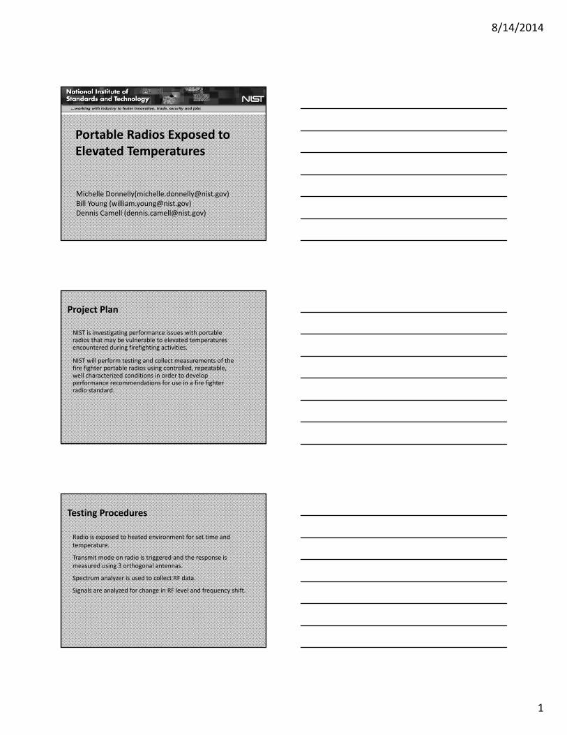
Portable Radios Exposed toElevated Temperatures
Michelle Donnelly([email protected])Bill Young ([email protected])Dennis Camell ([email protected])
Project Plan
NIST is investigating performance issues with portableradios that may be vulnerable to elevated temperaturesencountered during firefighting activities.
NIST will perform testing and collect measurements of thefire fighter portable radios using controlled, repeatable,well characterized conditions in order to developperformance recommendations for use in a fire fighterradio standard.
Testing Procedures
Radio is exposed to heated environment for set time andtemperature.
Transmit mode on radio is triggered and the response ismeasured using 3 orthogonal antennas.
Spectrum analyzer is used to collect RF data.
Signals are analyzed for change in RF level and frequency shift.
8/14/2014
2
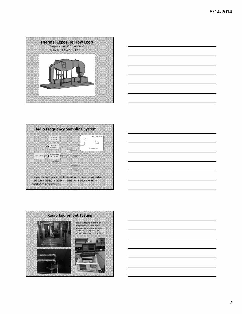
Thermal Exposure Flow LoopTemperatures 20 C to 300 CVelocities 0.5 m/s to 1.4 m/s
Radio Frequency Sampling System
3 axis antenna measured RF signal from transmitting radio.Also could measure radio transmission directly when inconducted arrangement.
SPECTRUM ANALYZER
RELAY CONTROL
POWER SUPPLY
COMPUTER
GPIB
+28 VDC
Heat Cycle Facility3 axis
antenna
RF coaxial cables
30dB attenuator and
adaptor
Test Radio
RF Radiated Test
RF Conducted Test
Test Radio
RF SWITCH
Radio Equipment TestingRadio on testing platform prior totemperature exposure (left).Measurement instrumentationinside flow loop (lower left).RF sampling equipment (below).
8/14/2014
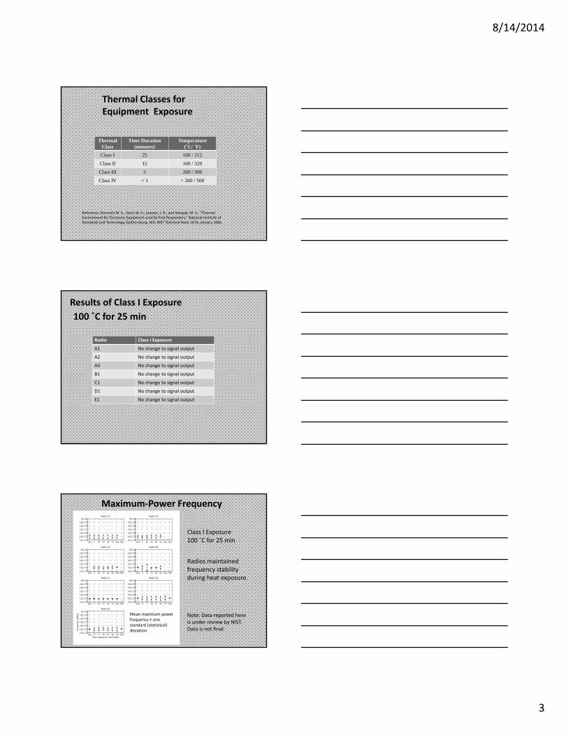
3
Thermal Classes forEquipment Exposure
Thermal Class
Time Duration (minutes)
Temperature(˚C/ ˚F)
Class I 25 100 / 212
Class II 15 160 / 320
Class III 5 260 / 500
Class IV < 1 > 260 / 500
Reference: Donnelly M. K., Davis W. D., Lawson, J. R., and Selepak, M. S., “ThermalEnvironment for Electronic Equipment used by First Responders,” National Institute ofStandards and Technology, Gaithersburg, MD, NIST Technical Note 1474, January 2006.
Results of Class I Exposure100 ˚C for 25 min
Radio Class I Exposure
A1 No change to signal output
A2 No change to signal output
A3 No change to signal output
B1 No change to signal output
C1 No change to signal output
D1 No change to signal output
E1 No change to signal output
Radios maintainedfrequency stabilityduring heat exposure.
Class I Exposure100 ˚C for 25 min
Maximum Power Frequency
Out 5 10 15 20 25 Out Out162.174162.175162.176162.177162.178162.179162.18
Radio A1
Out 5 10 15 20 25 Out Out162.174162.175162.176162.177162.178162.179162.18
Radio A2
Out 5 10 15 20 25 Out Out162.174162.175162.176162.177162.178162.179162.18
Radio A3
Out 5 10 15 20 25 Out Out162.174162.175162.176162.177162.178162.179162.18
Radio B1
Out 5 10 15 20 25 Out Out162.174162.175162.176162.177162.178162.179162.18
Radio C1
Out 0 5 10 15 20 25 Out162.174162.175162.176162.177162.178162.179162.18
Radio D1
Out 0 5 10 15 20 25 Out162.174162.175162.176162.177162.178162.179162.18
Radio E1
Freq
uenc
y (M
Hz)
Time exposed to heat (min)
Mean maximum powerfrequency ± onestandard (statistical)deviation
Note: Data reported hereis under review by NIST.Data is not final.
8/14/2014
4
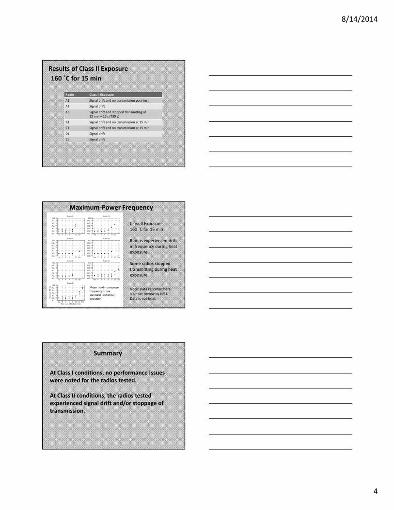
Results of Class II Exposure160 ˚C for 15 min
Radio Class II Exposure
A1 Signal drift and no transmission post test
A2 Signal drift
A3 Signal drift and stopped transmitting at12 min + 10 s (730 s)
B1 Signal drift and no transmission at 15 min
C1 Signal drift and no transmission at 15 min
D1 Signal drift
E1 Signal drift
Radios experienced driftin frequency during heatexposure.
Class II Exposure160 ˚C for 15 min
Maximum Power Frequency
Some radios stoppedtransmitting during heatexposure.
Out 3 6 9 12 15 Out162.174162.175162.176162.177162.178162.179162.18
Radio A1
Out 3 6 9 12 15 Out162.174162.175162.176162.177162.178162.179162.18
Radio A2
Out 3 6 9 12 15 Out162.174162.175162.176162.177162.178162.179162.18
Radio A3
Out 1.5 3 6 9 12 15 Out162.174162.175162.176162.177162.178162.179162.18
Radio B1
Out 3 6 9 12 15 Out162.174162.175162.176162.177162.178162.179162.18
Radio C1
Out 0 3 6 9 12 15 Out162.174162.175162.176162.177162.178162.179162.18
Radio D1
Out 0 3 6 9 12 15 Out162.174162.175162.176162.177162.178162.179162.18
Radio E1
Freq
uenc
y (M
Hz)
Time exposed to heat (min)
Mean maximum powerfrequency ± onestandard (statistical)deviation
Note: Data reported hereis under review by NIST.Data is not final.
Summary
At Class I conditions, no performance issueswere noted for the radios tested.
At Class II conditions, the radios testedexperienced signal drift and/or stoppage oftransmission.
8/14/2014
5
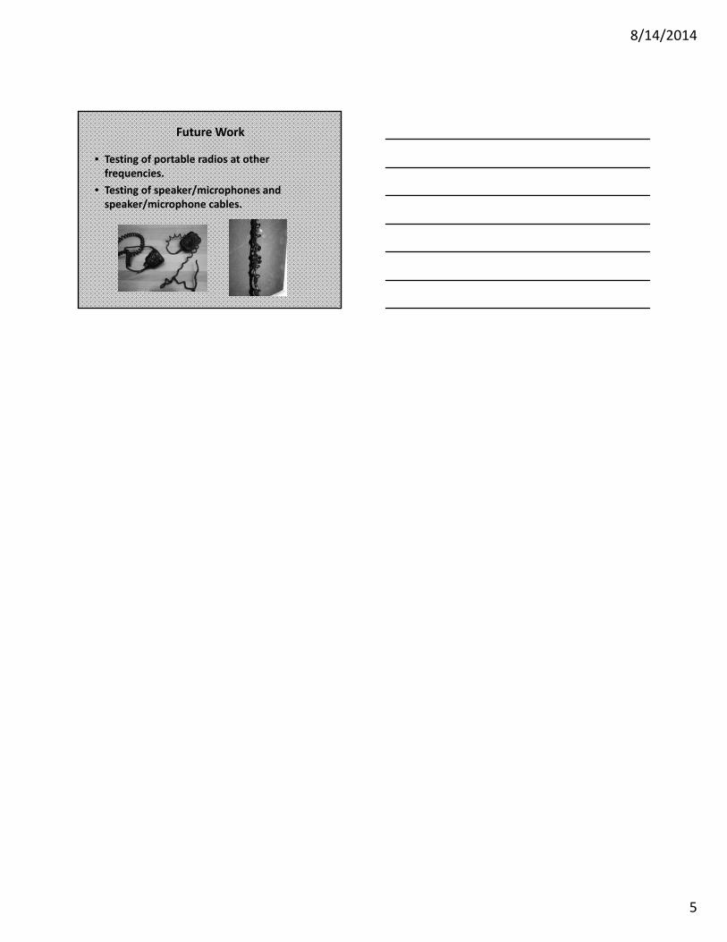
Future Work
• Testing of portable radios at otherfrequencies.
• Testing of speaker/microphones andspeaker/microphone cables.
8/14/2014
1
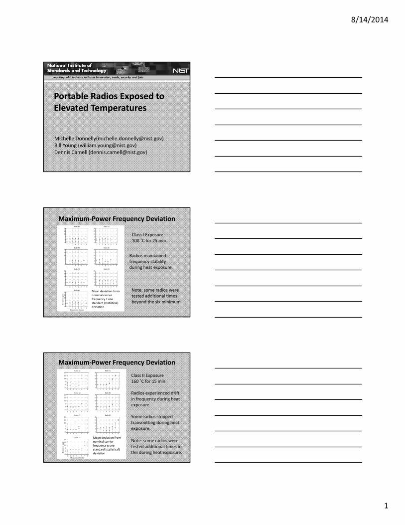
Portable Radios Exposed toElevated Temperatures
Michelle Donnelly([email protected])Bill Young ([email protected])Dennis Camell ([email protected])
Radios maintainedfrequency stabilityduring heat exposure.
Class I Exposure100 ˚C for 25 min
Maximum Power Frequency Deviation
1 2 3 4 5 6 7 8-5
05
101520
Radio A1
1 2 3 4 5 6 7 8-5
05
101520
Radio A2
1 2 3 4 5 6 7 8-505
101520
Radio A3
1 2 3 4 5 6 7 8-505
101520
Radio B1
1 2 3 4 5 6 7 8-5
05
101520
Radio C1
1 2 3 4 5 6 7 8-5
05
101520
Radio D1
1 2 3 4 5 6 7 8-505
101520
Radio E1
Dev
iatio
n (p
pm)
Measurement Number
Mean deviation fromnominal carrierfrequency ± onestandard (statistical)deviation
Note: some radios weretested additional timesbeyond the six minimum.
Radios experienced driftin frequency during heatexposure.
Class II Exposure160 ˚C for 15 min
Maximum Power Frequency Deviation
1 2 3 4 5 6 7 8-5
0
5
10
1520
Radio A1
1 2 3 4 5 6 7 8-5
0
5
10
1520
Radio A2
1 2 3 4 5 6 7 8-5
0
5
10
1520
Radio A3
1 2 3 4 5 6 7 8-5
0
5
10
1520
Radio B1
1 2 3 4 5 6 7 8-5
0
510
1520
Radio C1
1 2 3 4 5 6 7 8-5
0
510
1520
Radio D1
1 2 3 4 5 6 7 8-5
0
510
1520
Radio E1
Dev
iatio
n (p
pm)
Measurement Number
Mean deviation fromnominal carrierfrequency ± onestandard (statistical)deviation
Note: some radios weretested additional times inthe during heat exposure.
Some radios stoppedtransmitting during heatexposure.
8/14/2014
1
NPSTC’s Programmingand Management (PAM)tool.
S.J. Makky, Sr. - 22 JUL 14
NEOTWY• Who = NPSTC, National Public SafetyTelecommunications Council, specifically, PamMontanari, Radio PCR (programmingcompatibility requirements) Group Chair andTom Sorley, NPSTC Technology CommitteeChair
• What = “PAM,” an Excel spreadsheet thathelps determine cross manufacturerinteroperable parameter criteria for theCommunications Manager and COM L
S.J. Makky, Sr. - 22 JUL 14
NEOTWY
• Where – downloadable from:http://npstc.org/ in the upper right searchbox, enter PAM.
• When – originally made available APR2014. Current version is 2, with a version 3to be released very soon. Version 3includes NIFOG data.
S.J. Makky, Sr. – 22 JUL 14
8/14/2014
2
NEOTWY• How – Internet download, open access.• Why – In multi agency response to an officerdown situation in the Tampa Bay area in 2011where radios didn’t work when needed, tomitigate the number of unique crossmanufacturer variables in programming radioparameters. Provide “need to know” data.
• Caveats – Subject to revisions. Newtechnologies may supplant fields or parametervalues, or require wholesale revision.
S.J. Makky, Sr. - 22 JUL 14
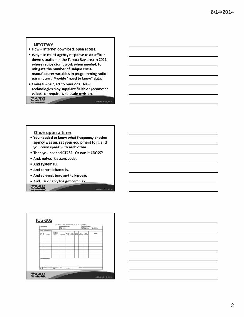
Once upon a time• You needed to know what frequency anotheragency was on, set your equipment to it, andyou could speak with each other.
• Then you needed CTCSS. Or was it CDCSS?• And, network access code.• And system ID.• And control channels.• And connect tone and talkgroups.• And… suddenly life got complex.
S.J. Makky, Sr. - 22 JUL 14
ICS-205
S.J. Makky, Sr. - 22 JUL 14
8/14/2014
3
S.J. Makky, Sr. - 22 JUL 14
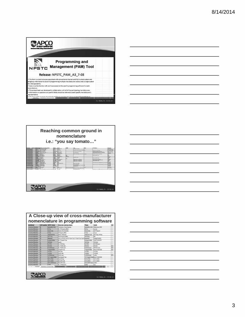
Reaching common ground in nomenclature
i.e.: “you say tomato…”
S.J. Makky, Sr. – 22 JUL 14
A Close-up view of cross-manufacturer nomenclature in programming software
S.J. Makky, Sr. – 22 JUL 14
8/14/2014
4
Let’s go to the spreadsheet…
S.J. Makky, Sr. – 22 JUL 14
S.J. Makky, Sr. – 22 JUL 14
Observations –
• Can be used in an acute situation, but will greatly aid in pre-planning.
• Illustrates the number of parameters which are involved in programming LMR equipment, particularly in specialized mobile radio systems (i.e., “trunked” systems).
• The “need to know” details behind the ICS-205 when sharing inter-system parameters for joint ops.
QuestionsCommentsConcernsDiscussion
S.J. Makky, Sr. – 22 JUL 14
8/14/2014
5
Presented materialcourtesy of NPSTC:http://npstc.org
S.J. Makky, Sr. – 22 JUL 14
8/14/2014
1
Hazardous Location Task Group met at UL HQin Northbrook, IL on 5/15 5/16Objective of meeting was to reach consensuson two issues:
Proposed NFPA 1802 text regarding risk ofexplosion protection requirements for LMRelectronic safety equipmentRationale regarding risk of explosion protectionrequirements for LMR electronic safetyequipment that can be applied consistentlyacross all other such electronic safety equipment
8/14/2014
2
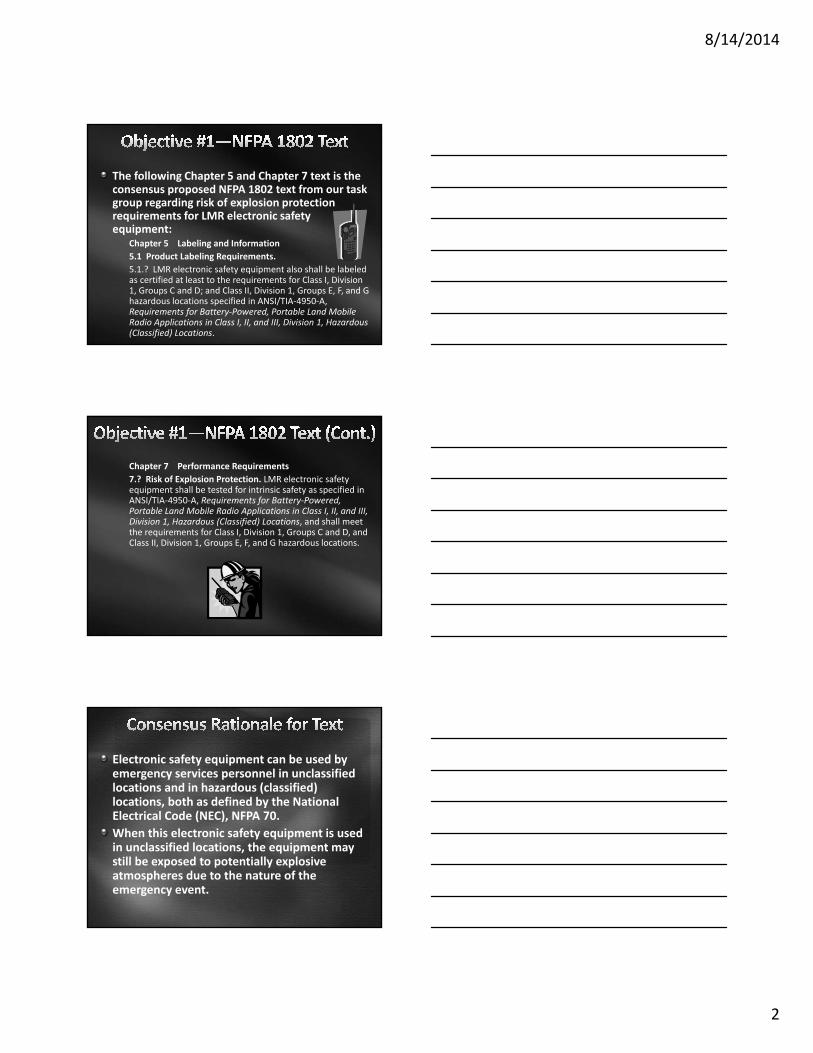
The following Chapter 5 and Chapter 7 text is theconsensus proposed NFPA 1802 text from our taskgroup regarding risk of explosion protectionrequirements for LMR electronic safetyequipment:
Chapter 5 Labeling and Information5.1 Product Labeling Requirements.5.1.? LMR electronic safety equipment also shall be labeledas certified at least to the requirements for Class I, Division1, Groups C and D; and Class II, Division 1, Groups E, F, and Ghazardous locations specified in ANSI/TIA 4950 A,Requirements for Battery Powered, Portable Land MobileRadio Applications in Class I, II, and III, Division 1, Hazardous(Classified) Locations.
Chapter 7 Performance Requirements7.? Risk of Explosion Protection. LMR electronic safetyequipment shall be tested for intrinsic safety as specified inANSI/TIA 4950 A, Requirements for Battery Powered,Portable Land Mobile Radio Applications in Class I, II, and III,Division 1, Hazardous (Classified) Locations, and shall meetthe requirements for Class I, Division 1, Groups C and D, andClass II, Division 1, Groups E, F, and G hazardous locations.
Electronic safety equipment can be used byemergency services personnel in unclassifiedlocations and in hazardous (classified)locations, both as defined by the NationalElectrical Code (NEC), NFPA 70.When this electronic safety equipment is usedin unclassified locations, the equipment maystill be exposed to potentially explosiveatmospheres due to the nature of theemergency event.
8/14/2014
3
This use of this electronic safety equipment insuch unclassified potentially explosiveatmospheres has some similar characteristicsto electronic equipment used in hazardous(classified) locations.While there are some similar characteristicsbetween electronic safety equipment used inunclassified potentially explosive atmospheresand electronic equipment used in certainhazardous (classified) locations, there are alsodissimilar characteristics, making a directcomparison not possible.
Therefore, since a direct comparison betweenelectronic safety equipment used inunclassified potentially explosive atmospheresand electronic equipment used in certainhazardous (classified) locations is not possible,the risk of explosion requirements shouldreflect the highest level of explosion protectionpossible in accordance with the NEC, while notadversely restricting necessary performancecharacteristics.
In accordance with the NEC, the following aretypes of explosion protection that could beconsidered applicable to electronic safetyequipment:
Under the Division system: Intrinsic Safety (forDivision 1 applications) and Nonincendive (forDivision 2 applications).Under the Zone system: Intrinsic Safety “ia” (forZone 0 applications); Intrinsic Safety “ib,”Encapsulation “m” and Increased Safety “e” (forZone 1 applications); and Nonincendive (for Zone2 applications).
8/14/2014
4
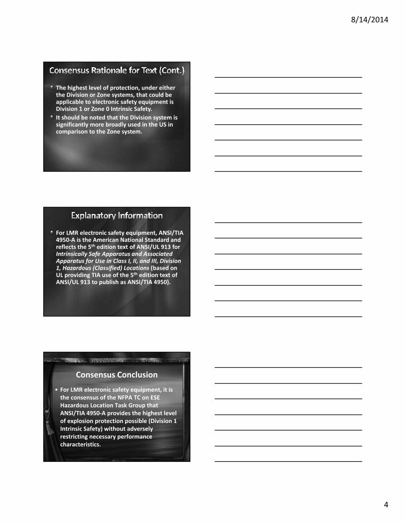
The highest level of protection, under eitherthe Division or Zone systems, that could beapplicable to electronic safety equipment isDivision 1 or Zone 0 Intrinsic Safety.It should be noted that the Division system issignificantly more broadly used in the US incomparison to the Zone system.
For LMR electronic safety equipment, ANSI/TIA4950 A is the American National Standard andreflects the 5th edition text of ANSI/UL 913 forIntrinsically Safe Apparatus and AssociatedApparatus for Use in Class I, II, and III, Division1, Hazardous (Classified) Locations (based onUL providing TIA use of the 5th edition text ofANSI/UL 913 to publish as ANSI/TIA 4950).
Consensus Conclusion• For LMR electronic safety equipment, it isthe consensus of the NFPA TC on ESEHazardous Location Task Group thatANSI/TIA 4950 A provides the highest levelof explosion protection possible (Division 1Intrinsic Safety) without adverselyrestricting necessary performancecharacteristics.
8/14/2014
5
All electronic safety equipment should besubjected to a similar consideration, withvarying results being reasonably possible (forexample, thermal imagers referencing Division2 Nonincendive requirements in ANSI/ISA12.12.01 versus PASS devices referencingIntrinsic Safety Division 1 requirements inANSI/UL 913). Further, it is reasonablypossible that over time, a differentdetermination may be reached based ontechnological advances in electronic safetyequipment.