Embed Size (px)
Citation preview

CH2M HILL
2485 Natomas Park Drive
Suite 600
Sacramento, CA 95833-2937
Tel 916.920.0300
Fax 916.920.8463
December 20, 2010 Mr. Pierre Martinez Siting Project Manager California Energy Commission 1516 Ninth Street Sacramento, CA 95814 Subject: Oakley Generating Station Project (09-AFC-4)
Appendix A- Revision 2 - Transition Cluster Phase II Interconnection Study Report
Dear Mr. Martinez:
Attached please find three (3) hardcopies of the Appendix A- Revision 2 - Transition Cluster Phase II Interconnection Study Report for the Oakley Generating Station (09-AFC-4). If you have any questions about this matter, please contact me at (916) 286-0278. Sincerely, CH2M HILL Douglas M. Davy, Ph.D. AFC Project Manager cc: POS List
Project File
DATE DEC 20 2010
RECD. DEC 20 2010
DOCKET09-AFC-4
Appendix A – Q258
Radback Energy
Contra Costa Generating Station Project
Final ReportRevision 2.0
November 18, 2010
This study has been completed in coordination with Pacific Gas & ElectricCompany per CAISO Tariff Appendix Y Large Generator Interconnection Procedures (LGIP) for Interconnection Requests in a Queue Cluster Window

Table of Contents
1. Executive Summary ..........................................................................................................2
2. Project and Interconnection Information ...........................................................................3
3. Study Assumptions............................................................................................................5
4. Power Flow Analysis .........................................................................................................5
4.1 Overloaded Transmission Facilities .........................................................................5
5. Short Circuit Analysis ........................................................................................................6
5.1 Short Circuit Study Input Data..................................................................................6
5.2 Results......................................................................................................................7
5.3 Preliminary Protection Requirements.......................................................................7
6. Reactive Power Deficiency Analysis.................................................................................7
7. Transient Stability Evaluation............................................................................................8
7.1 Transient Stability Study Scenarios..........................................................................8
7.2 Results......................................................................................................................9
8. Deliverability Assessment .................................................................................................9
8.1 On Peak Deliverability Assessment .........................................................................9
8.2 Off- Peak Deliverability Assessment ........................................................................9
9. Operational Studies...........................................................................................................9
10. Environmental Evaluation/Permitting..............................................................................10
10.1 CPUC General Order 131-D ..................................................................................10
10.2 CPUC Section 851 .................................................................................................12
11. Upgrades, Cost Estimates and Construction schedule estimates .................................12
12. Technical Requirements .................................................................................................13
13. Items not covered in this study........................................................................................15
Attachments:
1. Generator Machine Dynamic Data2. Dynamic Stability Plots3. Preliminary Protection Requirement4. Short Circuit Calculation Study Results5. Deliverability Assessment Results6. Allocation of Network Upgrades for Cost Estimates7. Results of Operational Studies

TRANSITION CLUSTER PHASE II INTERCONNECTION STUDY REPORTRADBACK ENERGY, CONTRA COSTA GENERATING STATION PROJECT
REVISION 2 OF THE FINAL REPORTNOVEMBER 18, 2010
2
1. Executive Summary
Radback Energy, an Interconnection Customer (IC), has submitted a completed Interconnection Request (IR) to the California Independent System Operator Corporation (CAISO) for their proposed Contra Costa Generating Station Project1
(Project). The Project is a combined cycle plant consisting of one (1) steam and two (2) gas turbine generators with a maximum net output to the CAISO Controlled Grid of 651 MW. The Project will be interconnected to the Pacific Gas and Electric Company’s (PG&E’s) Contra Costa Substation in Contra Costa County. The IC also selected an alternative POI, which is looping the Contra Costa PP – Moraga 230 kV Lines Nos. 1 and 2 into the Project switchyard. The proposed Commercial Operation Date (COD) of the Project is December 1, 2013.
In accordance with Federal Energy Regulatory Commission (FERC) approved Large Generator Interconnection Procedures (LGIP) for Interconnection Requests in a Queue Cluster Window (ISO Appendix Y), this project was grouped with “Greater Bay Area Transition Cluster Group” projects (TransitionCluster Phase II Study or Phase II study) to determine the impacts of the groupas well as impacts of this Project on the CAISO Controlled Grid.
The group report has been prepared separately identifying the combined impacts of all projects in the group on the CAISO Controlled Grid. This report focuses only on the impacts of this project.
The report provides the following:
1. Transmission system impacts caused by the Project,
2. System reinforcements necessary to mitigate the adverse impacts caused by theProject under various system conditions,
3. A list of required facilities and a non-binding, good faith estimate of this Project’s cost responsibility and time to construct these facilities.
The Phase II study results have determined that the Project contributes to overloading of four (4) transmission facilities for which mitigation plans have been proposed. In addition, the Project is also partly responsible for overstressing one (1) circuit breaker at Pittsburg PP Switching Station.
The Project did not violate any parts of voltage criteria and hence caused no adverse voltage impacts on the grid. Also, the Project did not significantly impact the transmission system’s transient stability performance following selected contingencies.
The non-binding cost estimate of Interconnection Facilities2 to interconnect the Project would be approximately $3.8 million exclusive of ITCC3. The non-binding
1 This Project is also referred to as Oakley Generating Station by the IC.2 The transmission facilities necessary to physically and electrically interconnect the Project to the CAISO Controlled
Grid at the point of interconnection.

TRANSITION CLUSTER PHASE II INTERCONNECTION STUDY REPORTRADBACK ENERGY, CONTRA COSTA GENERATING STATION PROJECT
REVISION 2 OF THE FINAL REPORTNOVEMBER 18, 2010
3
cost estimate for the Network Upgrades4 to interconnect the Project would be approximately $21.5 million.
The non-binding construction schedule to engineer and construct the facilities is approximately 18-24 months from the signing of the Large Generator InterconnectionAgreement (LGIA).
2. Project and Interconnection Information
Table 2-1 provides general information about the Project.
Table 2-1: Project General InformationProject Location Contra Costa County, California
PG&E Planning Area Greater Bay Area
Number and Type of Generators
Two Gas Turbines (each rated for 222 MW) and One Steam Turbine (rated for 228 MW)
Interconnection Voltage 230 kV
Maximum Generator Output 672.3 MW
Generator Auxiliary Load 21.3 MW
Maximum Net Output to Grid 651 MW
Power Factor Range 0.90 Lagging to 0.95 Leading5
Step-up TransformerThree transformers, each three-phase, rated for 18/230 kV, 159/212/265 MVA with 10% impedance on 1359 MVA base
Point of Interconnection Contra Costa Substation 230 kV bus
Alternative Point of Interconnection
Looping into the Contra Costa-Moraga 230 kV Lines Nos. 1 and 2.
Commercial Operation Date December 1, 2013
Figure 2-1 provides the map for the Project and the transmission facilities in the vicinity. Figure 2-2 shows the conceptual single line diagram of the Project.
3 Income Tax Component of Contribution (currently at 34%)4 The transmission facilities, other than Interconnection Facilities, beyond the point of interconnection necessary to
physically and electrically interconnect the Project safely and reliably to the CAISO Controlled Grid.5 PG&E’s Interconnection Handbook requires that the Project be able to meet power factor requirements of 90 percent
lagging and 95 percent leading.

TRANSITION CLUSTER PHASE II INTERCONNECTION STUDY REPORTRADBACK ENERGY, CONTRA COSTA GENERATING STATION PROJECT
REVISION 2 OF THE FINAL REPORTNOVEMBER 18, 2010
4
Figure 2-1: Vicinity Map
Figure 2-2: Proposed Single Line Diagram
TRANSITION CLUSTER PHASE II INTERCONNECTION STUDY REPORTRADBACK ENERGY, CONTRA COSTA GENERATING STATION PROJECT
REVISION 2 OF THE FINAL REPORTNOVEMBER 18, 2010
5
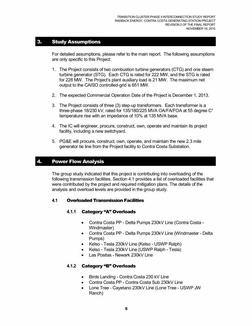
3. Study Assumptions
For detailed assumptions, please refer to the main report. The following assumptions are only specific to this Project:
1. The Project consists of two combustion turbine generators (CTG) and one steam turbine generator (STG). Each CTG is rated for 222 MW, and the STG is rated for 228 MW. The Project’s plant auxiliary load is 21 MW. The maximum net output to the CAISO controlled-grid is 651 MW.
2. The expected Commercial Operation Date of the Project is December 1, 2013.
3. The Project consists of three (3) step-up transformers. Each transformer is a three-phase 18/230 kV, rated for 135/180/225 MVA OA/FA/FOA at 55 degree C°temperature rise with an impedance of 10% at 135 MVA base.
4. The IC will engineer, procure, construct, own, operate and maintain its project facility, including a new switchyard.
5. PG&E will procure, construct, own, operate, and maintain the new 2.3 mile generator tie line from the Project facility to Contra Costa Substation.
4. Power Flow Analysis
The group study indicated that this project is contributing into overloading of the following transmission facilities. Section 4.1 provides a list of overloaded facilities that were contributed by the project and required mitigation plans. The details of the analysis and overload levels are provided in the group study.
4.1 Overloaded Transmission Facilities
4.1.1 Category “A” Overloads
Contra Costa PP - Delta Pumps 230kV Line (Contra Costa -Windmaster)
Contra Costa PP - Delta Pumps 230kV Line (Windmaster - Delta Pumps)
Kelso - Tesla 230kV Line (Kelso - USWP Ralph) Kelso - Tesla 230kV Line (USWP Ralph - Tesla) Las Positas - Newark 230kV Line
4.1.2 Category “B” Overloads
Birds Landing - Contra Costa 230 kV Line Contra Costa PP - Contra Costa Sub 230kV Line Lone Tree - Cayetano 230kV Line (Lone Tree - USWP JW
Ranch)
TRANSITION CLUSTER PHASE II INTERCONNECTION STUDY REPORTRADBACK ENERGY, CONTRA COSTA GENERATING STATION PROJECT
REVISION 2 OF THE FINAL REPORTNOVEMBER 18, 2010
6
Lone Tree - Cayetano 230kV Line (USWP JW Ranch - Cayetano) Kelso - Tesla 230kV Line (Kelso - USWP Ralph)* Kelso - Tesla 230kV Line (USWP Ralph - Tesla)*
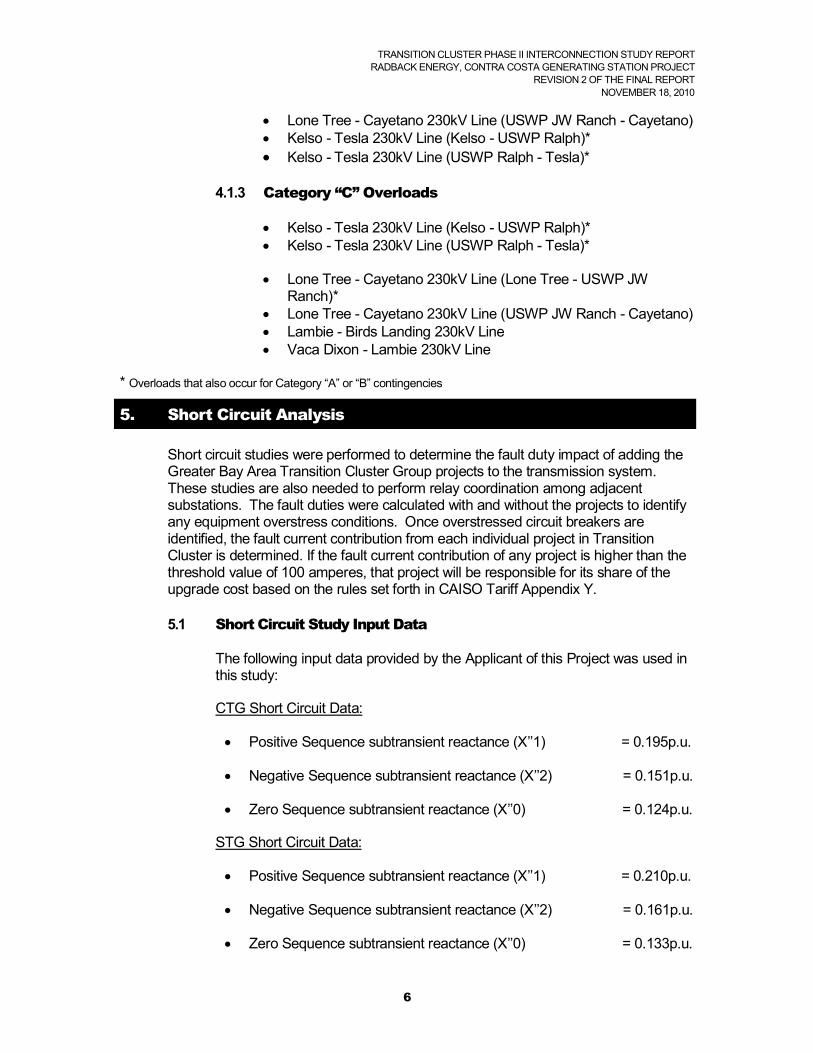
4.1.3 Category “C” Overloads
Kelso - Tesla 230kV Line (Kelso - USWP Ralph)* Kelso - Tesla 230kV Line (USWP Ralph - Tesla)*
Lone Tree - Cayetano 230kV Line (Lone Tree - USWP JW Ranch)*
Lone Tree - Cayetano 230kV Line (USWP JW Ranch - Cayetano) Lambie - Birds Landing 230kV Line Vaca Dixon - Lambie 230kV Line
* Overloads that also occur for Category “A” or “B” contingencies
5. Short Circuit Analysis
Short circuit studies were performed to determine the fault duty impact of adding theGreater Bay Area Transition Cluster Group projects to the transmission system.These studies are also needed to perform relay coordination among adjacent substations. The fault duties were calculated with and without the projects to identify any equipment overstress conditions. Once overstressed circuit breakers are identified, the fault current contribution from each individual project in Transition Cluster is determined. If the fault current contribution of any project is higher than the threshold value of 100 amperes, that project will be responsible for its share of the upgrade cost based on the rules set forth in CAISO Tariff Appendix Y.
5.1 Short Circuit Study Input Data
The following input data provided by the Applicant of this Project was used in this study:
CTG Short Circuit Data:
Positive Sequence subtransient reactance (X’’1) = 0.195p.u.
Negative Sequence subtransient reactance (X’’2) = 0.151p.u.
Zero Sequence subtransient reactance (X’’0) = 0.124p.u.
STG Short Circuit Data:
Positive Sequence subtransient reactance (X’’1) = 0.210p.u.
Negative Sequence subtransient reactance (X’’2) = 0.161p.u.
Zero Sequence subtransient reactance (X’’0) = 0.133p.u.

TRANSITION CLUSTER PHASE II INTERCONNECTION STUDY REPORTRADBACK ENERGY, CONTRA COSTA GENERATING STATION PROJECT
REVISION 2 OF THE FINAL REPORTNOVEMBER 18, 2010
7
Station Step-up Transformers (total of three)
Each transformer is a three-phase 18/230 kV rated for 135/180/225 MVA OA/FA/FOA at 55 degree C temperature rise with an impedance of 10% at 135 MVA base.
5.2 Results
The available short circuit duty at the buses electrically adjacent to Transition Cluster projects is listed in Attachment 4. This data was used to determine if any equipment is overstressed by the interconnection of the Transition Cluster projects.
Using these short-circuit study results, an initial breaker evaluation found that this Project contributes more than the threshold value of 100 Amps to the following overstressed circuit breaker:
Pittsburg PP 230 kV Switching Station CB 672
5.3 Preliminary Protection Requirements
Per Section G2.1 of the PG&E Interconnection Handbook, PG&E protection requirements are designed and intended to protect PG&E’s system only. The applicant is responsible for the protection of its own system and equipment and must meet the requirements in the PG&E Interconnection Handbook.
These Preliminary Protection Requirements are based upon an interconnection plan as shown in Figure 2-2. The Preliminary Protection Requirements are detailed in Attachment 3.
Protection requirements may include, but are not limited to, direct transfer trip schemes installed at PG&E and IC facilities. The IC is responsible for installing the leased lines used for direct transfer trip communication and the necessary direct transfer trip transmitters.
6. Reactive Power Deficiency Analysis
The power flow studies of Category “B” and Category “C” contingencies indicate that the Transition Cluster projects did not cause voltage drops of 5% or more from the pre-project levels, or cause the PG&E system to fail to meet applicable voltage criteria. This project, therefore, did not cause any adverse voltage impacts on the CAISO Controlled Grid.

TRANSITION CLUSTER PHASE II INTERCONNECTION STUDY REPORTRADBACK ENERGY, CONTRA COSTA GENERATING STATION PROJECT
REVISION 2 OF THE FINAL REPORTNOVEMBER 18, 2010
8
7. Transient Stability Evaluation
Transient Stability studies were conducted using the 2013 summer peak full loop base cases to ensure that the transmission system remains in operating equilibrium, as well as operating in a coordinated fashion, through abnormal operating conditions after the Transition Cluster projects begin operation. The generator dynamic data used in the study for this Project is shown in Attachment 1.
7.1 Transient Stability Study Scenarios
Disturbance simulations were performed for a study period of 10 seconds to determine whether the Transition Cluster projects will create any system instability during a variety of line and generator outages. For this Project, the following line and generator outages were evaluated:
7.1.1 Category “B” Contingencies:
Full load rejection of 651 MW of the Project.
A three-phase close-in fault on the Contra Costa PP – Contra Costa Substation 230 kV Line at the Contra Costa Substation 230 kV bus with normal clearing time followed by the loss of the Contra Costa PP – Contra Costa Substation 230 kV Line.
A three-phase close-in fault on the Birds Landing Switching Station – Contra Costa Substation 230 kV Line at the Contra Costa Substation 230 kV bus with normal clearing time followed by the loss of the Birds Landing Switching Station – Contra Costa Substation 230 kV Line.
7.1.2 Category “C” Contingencies:
A three-phase fault on the Contra Costa Substation 230 kV Bus #1 with normal clearing time
A three-phase fault on the Contra Costa Substation 230 kV Bus #2 with normal clearing time
A three-phase close-in fault on the Contra Costa Substation 230 kV Bus #1 with normal clearing time followed by the loss of the Contra Costa PP – Contra Costa Substation 230 kV Line and the Birds Landing Switching Station – Contra Costa Substation 230 kV Line.

TRANSITION CLUSTER PHASE II INTERCONNECTION STUDY REPORTRADBACK ENERGY, CONTRA COSTA GENERATING STATION PROJECT
REVISION 2 OF THE FINAL REPORTNOVEMBER 18, 2010
9
7.2 Results
The study concluded that the Project would not cause the transmission system to go unstable under Category “B” and Category “C” outages.
The results of the study are provided in the form of plots in Attachment 2.
8. Deliverability Assessment
8.1 On Peak Deliverability Assessment
CAISO performed an On-Peak Deliverability Assessment on the 2013 Summer Peak conditions to determine the capability of the projects to be deliverable to the aggregated of load. The study was conducted using the assumptions and methodologies described in the Off-Peak Deliverability Assessment Methodology which is available on the CAISO website at http://www.caiso.com/23d7/23d7e41c14580.pdf.
The power flow study results for Category “A”, “B”, and “C” are detailed in Attachment 5.
8.2 Off- Peak Deliverability Assessment
A modified version of the power flow 2013 Summer Off-Peak base case was created to perform the off-peak deliverability assessment of the Transition Cluster projects. The study was conducted using the assumptions and methodologies described in the Off-Peak Deliverability Assessment Methodology which is available on the CAISO website at http://www.caiso.com/23d7/23d7e46815090.pdf.
The impacts of this project are shown in Attachment 5.
9. Operational Studies
Operational studies including Power Flow, Short Circuit, Transient Stability, and Voltage assessment were performed on a year-by-year basis by adding projects in the base cases based on their Commercial Operation Date (COD). The purpose of these studies was to determine whether or not the required Reliability Network Upgrades and Delivery Network Upgrades can be constructed in a timely manner to safely and reliably interconnect this Project on the CAISO Controlled Grid.
The detailed results of the Operational studies are shown in Attachment 7. A summary of analyses related to this Project’s COD is presented in the following paragraphs:
Power flow analysis indicated that the following facilities will be overloaded:

TRANSITION CLUSTER PHASE II INTERCONNECTION STUDY REPORTRADBACK ENERGY, CONTRA COSTA GENERATING STATION PROJECT
REVISION 2 OF THE FINAL REPORTNOVEMBER 18, 2010
10
1. Contra Costa - Brentwood 230kV Line2. Contra Costa PP - Delta Pumps 230kV Line 3. Delta Pumps - Tesla 230kV Line 4. Kelso - Tesla 230kV Line 5. Las Positas - Newark 230kV Line6. Birds Landing - Contra Costa 230 kV Line7. Contra Costa PP - Contra Costa Sub 230kV Line8. Lone Tree - Cayetano 230kV Line 9. Newark 230/115kV Bank #1110. Castro Valley - Newark 230kV Line 11. Lambie - Birds Landing 230kV Line12. Moraga - Castro Valley 230kV Line13. North Dublin - Cayetano 230kV Line14. Trimble-San Jose “B” 115kV Line15. Vaca - Lambie 230kV Line
Short Circuit analysis indicated that some circuit breakers will be overstressed at the following substations:
1. Pittsburg PP Switching Station (Circuit Breaker 672)
Transient Stability analysis indicated that the system will remain stable under the selected disturbances in the vicinity of the project and no adverse stability impacts were found.
Voltage Assessment indicated that the Transmission System voltages under Category “B” and Category “C” contingency conditions were well within the PG&Eoperating guidelines, and the voltage deviations were within the allowable NERC/WECC criteria.
Based on the estimated construction time for the above overloaded facilities, PG&Ecannot guarantee that those facilities will be in service to meet the IC’s COD. However, the CAISO believes that congestion management and/or operating procedures can be applicable in the interim period until the upgrades are completed. The Project will be treated as an “Energy Only” project during this interim period.
10. Environmental Evaluation/Permitting
10.1 CPUC General Order 131-D
PG&E is subject to the jurisdiction of the California Public Utilities Commission (CPUC) and must comply with CPUC General Order 131-D (Order) on the construction, modification, alteration, or addition of all electric transmission facilities (i.e., lines, substations, switchyards, etc.). This includes facilities to be constructed by others and deeded to PG&E. In most cases where PG&E’s electric facilities are under 200 kV and are part of a larger project (i.e., electric generation plant), the Order exempts PG&E from obtaining an approval from the CPUC provided its planned facilities have been included in the larger project’s California Environmental Quality Act

TRANSITION CLUSTER PHASE II INTERCONNECTION STUDY REPORTRADBACK ENERGY, CONTRA COSTA GENERATING STATION PROJECT
REVISION 2 OF THE FINAL REPORTNOVEMBER 18, 2010
11
(CEQA) review, the review has included circulation with the State Clearinghouse, and the project’s lead agency (i.e., California Energy Commission) finds no significant unavoidable environmental impacts. PG&E or the project developer may proceed with construction once PG&E has filed notice with the CPUC and the public on the project’s exempt status, and the public has had a chance to protest PG&E’s claim of exemption. If PG&E facilities are not included in the larger project’s CEQA review, or if the project does not qualify for the exemption, PG&E may need to seek approval from the CPUC (i.e., Permit to Construct) taking as much as 18 months or more since the CPUC would need to conduct its own environmental evaluation (i.e., Negative Declaration or Environmental Impact Report).
When PG&E’s transmission lines are designed for immediate or eventual operation at 200 kV or more, the Order requires PG&E to obtain a Certificate of Public Convenience and Necessity (CPCN) from the CPUC unless one of the following exemptions applies: the replacement of existing power line facilities or supporting structures with equivalent facilities or structures, the minor relocation of existing facilities, the conversion of existing overhead lines (greater than 200 kV) to underground, or the placing of new or additional conductors, insulators, or their accessories on or replacement of supporting structures already built. Obtaining a CPCN can take as much as 18 months or more if the CPUC needs to conduct its own CEQA review, while a CPCN with the environmental review already done takes only 4-6 months or less.
Regardless of the voltage of PG&E’s interconnection facilities, PG&E recommends that the project proponent include those facilities in its project description and application to the lead agency performing CEQA review onthe project. The lead agency must consider the environmental impacts of the interconnection electric facility, whether built by the developer with the intent to transfer ownership to PG&E or to be built and owned by PG&E directly. If the lead agency makes a finding of no significant unavoidable environmental impacts from construction of substation or under-200 kV power line facilities, PG&E may be able to file an Advice Letter with the CPUC and publish public notice of the proposed construction of the facilities. The noticing process takes about 90 days if no protests are filed, but should be done as early as possible so that a protest does not delay construction. PG&E has no control over the time it takes the CPUC to respond when issues arise. If the protest is granted, PG&E may then need to apply for a formal permit to construct the project (i.e., Permit to Construct). Facilities built under this procedure must also be designed to include consideration of electric and magnetic field (EMF) mitigation measures pursuant to PG&E “EMF Design Guidelines for New Electrical Facilities: Transmission, Substation and Distribution”. For projects that are not eligible for the Advice Letter/notice process but have already undergone CEQA review, PG&E would likely be able to file a “short-form” CPCN or PTC application, which takes about 4-6 months to process.
Please see Section III, in General Order 131-D. This document can be found in the CPUC’s web page at:
http://www.cpuc.ca.gov/PUBLISHED/GENERAL_ORDER/589.htm

TRANSITION CLUSTER PHASE II INTERCONNECTION STUDY REPORTRADBACK ENERGY, CONTRA COSTA GENERATING STATION PROJECT
REVISION 2 OF THE FINAL REPORTNOVEMBER 18, 2010
12
10.2 CPUC Section 851
Because PG&E is subject to the jurisdiction of the CPUC, it must also comply with Public Utilities Code Section 851. Among other things, this code provision requires PG&E to obtain CPUC approval of leases and licenses to use PG&E property, including rights-of-way granted to third parties for Interconnection Facilities. Obtaining CPUC approval for a Section 851 application can take several months, and requires compliance with the California Environmental Quality Act (CEQA). PG&E recommends that Section 851 issues be identified as early as possible so that the necessary application can be prepared and processed. As with GO 131-D compliance, PG&E recommends that the project proponent include any facilities that may be affected by Section 851 in the lead agency CEQA review so that the CPUC does not need to undertake additional CEQA review in connection with its Section 851 approval.
11. Upgrades, Cost Estimates and Construction schedule estimates
To determine the cost responsibility of each generation project in Transition Cluster, the CAISO developed cost allocation factors based on the individual contribution of each project (Attachment 6). The cost allocation for the Interconnection Facilities and Network Upgrades for which this Project is solely responsible is as follows:
Table 11-1: Upgrades, Estimated Costs, and Estimated Time to Construct Summary
Type of Upgrade Upgrade DescriptionCost
Allocation Factor
Estimated Cost x 1000
Estimated Time to
Construct (Note 1)
PTO’s Interconnection
Facilities
(Note 2)
Work at the IC’s site
Pre-parallel inspection, testing, SCADA/EMS setup, meters, etc.
Land engineering support and permitting activities
100% $60012-18 Months
New 230 kV generator tie line
Engineer, procure, and construct a 2.3 mile transmission line from Project site to Contra Costa Substation
100% $3,16318-24 Months
Reliability Network
Upgrades
CommunicationsSCADA/EMS, programming, testing,
screening at TOC and Switching Center
100% $250 12 Months
Lonetree – Cayetano 230 kV Line Line re-rate 63.5% $95 12 Months
SPS to mitigate overloads on 1) Contra Costa PP – Contra Costa
Sub 230 kV Line2) Birds Landing – Contra Costa
230 kV Line3) Vaca – Lambie 230 kV Line, and4) Lambie – Birds Landing 230 kV
Line
Install SPS to drop generation at Q258
89.3% $893 12 months

TRANSITION CLUSTER PHASE II INTERCONNECTION STUDY REPORTRADBACK ENERGY, CONTRA COSTA GENERATING STATION PROJECT
REVISION 2 OF THE FINAL REPORTNOVEMBER 18, 2010
13
Delivery Network
Upgrades
Contra Costa PP – Delta Pumps 230 kV Line (Contra Costa –Windmaster)
Reconductor 16.5 miles of transmission line with a high capacity conductor
79.6% $7,80118-24
months
Contra Costa PP – Delta Pumps 230 kV Line (Windmaster – Delta Pumps)
Reconductor 1.8 miles of transmission line with a high capacity conductor
79.6% $95518-24
months
Kelso – Tesla 230 kV Line (Kelso – USWP Ralph)
Reconductor 3.3 miles of transmission line with a high capacity conductor
34.9% $59318-24
months
Kelso – Tesla 230 kV Line (USWP Ralph - Tesla)
Reconductor 4.7 miles of transmission line with a high capacity conductor
34.9% $94218-24
months
Los Positas – Newark 230 kV Line Reconductor 21 miles of transmission line with a high capacity conductor 79.7% $9,963
18-24 months
Total $25,255
Note 1: The Estimated Time to Construct is the schedule for the PTO to complete the construction activities only.
Note 2: The Interconnection Customer is obligated to fund these upgrades and will not be reimbursed.
The non-binding construction schedule to engineer and construct the facilities is based on the assumptions outlined in Section 3 of this report, and is applicable from the signing of the Large Generator Interconnection Agreement (LGIA). This is alsobased upon the assumption that the environmental permitting obtained by the IC is adequate for permitting all PG&E activities.
It is assumed that the IC will include the PG&E Interconnection Facilities and Network Upgrades work scope, as they apply to work within public domains, in its environmental impact report to the CPUC. However, note that CPUC may still require PG&E to obtain a Permit to Construct (PTC) or a Certificate of Public Convenience and Necessity (CPCN) for the generator tie line and Network Upgrades work associated with the Project. Hence, the facilities needed for the project interconnection could require an additional two to three years to complete. The cost for obtaining any of this type of permitting is not included in the above estimates.
12. Technical Requirements
The PG&E Interconnection Handbook explain the technical requirements for interconnection of loads and generators to PG&E’s transmission system. The Interconnection Handbook documents facility connection requirements to the PG&E system as required in NERC Standard FAC-001-0. They are based on applicable FERC and CPUC rules and tariffs (e.g., Electric Rules 2, 21 and 22), as well as accepted industry practices and standards. In addition to providing reliability, these technical requirements are consistent with safety for PG&E workers and the public.
The PG&E Interconnection Handbook applies to Retail and Wholesale Entities, which own or operate generation, transmission, and end user facilities that are physically connected to, or desire to physically connect to PG&E’s electric system. All technical

TRANSITION CLUSTER PHASE II INTERCONNECTION STUDY REPORTRADBACK ENERGY, CONTRA COSTA GENERATING STATION PROJECT
REVISION 2 OF THE FINAL REPORTNOVEMBER 18, 2010
14
requirements described or referred to in the Handbook apply to new or re-commissioned Generation Facilities. The Generation Interconnection Handbook comprising sections G-1 through G-5 applies to Generation Entities.
PG&E has established standard operating, metering and equipment protection requirements for loads and generators. The Interconnection Handbook covers such requirements for all transmission-level load and generation entities wishing to interconnect with PG&E’s electric system. Additional, project-specific requirements may apply and are documented in this SIS report.
The PG&E Interconnection Handbook includes, but is not limited to such operating requirements as the following:
The Project must be able to meet the power factor requirements of 90 percent lagging and 95 percent leading.
The Project must have Automatic Voltage Regulation (AVR) and be able to maintain the generator voltage under steady-state conditions within ±0.5 percent of any voltage level between 95 percent and 105 percent of the rated generator voltage.
Generators must also meet all applicable CAISO, NERC, and Western Electric Coordinating Council (WECC) standards. NERC and WECC standards include, but are not limited to such requirements as the following:
The Project must be able to remain on line during voltage disturbances up to the time periods and associated voltage levels as required by the WECC Low Voltage Ride Through (LVRT) standards that are in-line with FERC Order No. 161-A. The WECC LVRT standard is available on the WECC web site at:
http://www.wecc.biz/committees/StandingCommittees/PCC/TSS/Shared%20Documents/Voltage%20Ride%20Through%20White%20Paper.pdf
Currently NERC is working on a Voltage Ride Through standard, PRC-024-1, that would be applicable to all generators interconnecting to the transmission grid. Until PRC-024-1 is effective, PG&E and the CAISO will require that all generators comply with the existing WECC LVRT requirements. The PRC-024-1 standard Draft 1 can be found on the NERC web site at
http://www.nerc.com/docs/standards/sar/PRC-024-1_Draft1_2009Feb17.pdf
All generators must satisfy the requirements of the PG&E’s Interconnection Handbook and meet all applicable CAISO, NERC, and WECC standards. PG&E will not agree to interconnect any new generators unless all technical and contractual requirements are met.
The IC should be aware that the information in the PG&E Interconnection Handbook is subject to change. Parties interconnecting to the PG&E electric system should

TRANSITION CLUSTER PHASE II INTERCONNECTION STUDY REPORTRADBACK ENERGY, CONTRA COSTA GENERATING STATION PROJECT
REVISION 2 OF THE FINAL REPORTNOVEMBER 18, 2010
15
verify with their PG&E representative that they have the latest versions. The PG&E Interconnection Handbook is available on the PG&E web site at:
http://www.pge.com/about/rates/tariffbook/ferc/tih/
13. Items not covered in this study
The Phase II Study does not address any requirements for standby power that the Project may require. The IC should contact their PG&E Generation Interconnection Services representative regarding this service.
Note: The IC is urged to contact their PG&E Generation Interconnection Services representative promptly regarding stand-by service in order to ensure its availability for the project’s start-up date.

BEFORE THE ENERGY RESOURCES CONSERVATION AND DEVELOPMENT COMMISSION OF THE STATE OF CALIFORNIA
1516 NINTH STREET, SACRAMENTO, CA 95814 1-800-822-6228 – WWW.ENERGY.CA.GOV
APPLICATION FOR CERTIFICATION Docket No. 09-AFC-4 FOR THE OAKLEY GENERATING STATION PROOF OF SERVICE
(Revised 11/17/2010)
APPLICANT ENERGY COMMISSION
Greg Lamberg, Sr. Vice President RADBACK ENERGY 145 Town & Country Drive, #107 Danville, CA 94526 [email protected]
JAMES D. BOYD Vice Chair and Presiding Member [email protected]
APPLICANT’S CONSULTANTS ROBERT B. WEISENMILLER Commissioner and Associate Member [email protected]
Douglas Davy CH2M HILL 2485 Natomas Park Drive, Suite 600 Sacramento, CA 95833 [email protected]
Kourtney Vaccaro Hearing Officer [email protected],ca.us
COUNSEL FOR APPLICANT Pierre Martinez Siting Project Manager [email protected]
Scott Galati Marie Mills Galati & Blek, LLP 455 Capitol Mall, Suite 350 Sacramento, CA 95814 [email protected] [email protected]
Kevin Bell Staff Counsel [email protected]
INTERESTED AGENCIES
Jennifer Jennings Public Adviser E-mail preferred [email protected]
California ISO E-mail Preferred [email protected]
INTERVENORS
Robert Sarvey 501 W. Grantline Road Tracy, CA 95376 [email protected]
*indicates change 1

DECLARATION OF SERVICE
I, Mary Finn, declare that on November 19, 2010, I served and filed copies of the attached Oakley Generating Station Project (09-AFC-4) Appendix A- Revision 2 - Transition Cluster Phase II Interconnection Study Report
[
. The original document, filed with the Docket Unit, is accompanied by a copy of the most recent Proof of Service list, located on the web page for this project at: http://www.energy.ca.gov/sitingcases/contracosta/index.html]. The document has been
sent to both the other parties in this proceeding (as shown on the Proof of Service list) and to the Commission’s Docket Unit, in the following manner:
(Check all that Apply)
For service to all other parties:
sent electronically to all email addresses on the Proof of Service list; ___x__ _____
by personal delivery; by delivering on this date, for mailing with the United States Postal Service with first-class postage thereon fully prepaid, to the name and address of the person served, for mailing that same day in the ordinary course of business; that the envelope was sealed and placed for collection and mailing on that date to those addresses NOT marked “email preferred.”
AND
For filing with the Energy Commission:
x sending an original paper copy and one electronic copy, mailed to the address below (preferred method);
OR _____depositing in the mail an original and 12 paper copies, as follows:
CALIFORNIA ENERGY COMMISSION Attn: Docket No. 09-AFC-4 1516 Ninth Street, MS-4 Sacramento, CA 95814-5512 [email protected]
I declare under penalty of perjury that the foregoing is true and correct, that I am employed in the county where this mailing occurred, and that I am over the age of 18 years and not a party to the proceeding.
Mary Finn