Embed Size (px)
Citation preview

July 21, 2017
CALL NO. 300
CONTRACT ID NO. 171025
ADDENDUM # 1
Subject: Bell County, FD04 SPP 007 0119 000-004
Letting July 28, 2017
(1)Revised – Plans – S1 & S2
(2)Revised – Special Note – Pages 14-17 of 127
(3)Revised - Bid Items – Pages 123-127 of 127
(4)Added - Special Note – Pages 1-2 of 2
Proposal revisions are available at http://transportation.ky.gov/Construction-
Procurement/.
Plan revisions are available at http://www.lynnimaging.com/kytransportation/.
If you have any questions, please contact us at 502-564-3500.
Sincerely,
Rachel Mills, P.E.
Director
Division of Construction Procurement
RM:ks
Enclosures

ITEM NUMBER
DRAWING NO.
SHEET NO.
Commonwealth of Kentucky
DEPARTMENT OF HIGHWAYSCOUNTY
ROUTE CROSSING
PREPARED BY
DETAILED BY:
DESIGNED BY:
DATE: CHECKED BY
REVISION DATE
20-J
UL-2017
U:\
Brid
ges\
Walk
up
Work\
Culv
ert
mark
ups\
Sta 60
+25_001.
dgn
jose
ph.vanzee
US
ER
NA
ME:
FIL
E
NA
ME:
DA
TE:
E-S
HEET
NA
ME:
Structural DesignDivision of
SINGLE 6.0 x 6.0 CULVERT
S1
ESTIMATE OF QUANTITIES
BID CODE ITEM QUANTITY UNIT
Class "A" Concrete C.Y.
Reinforcement Lb
Foundation Preparation L.S.
C.Y.
GENERAL NOTES
SPECIFICATIONS: All references to the standard Specifications are to the
current edition of the Kentucky Department of Highways Standard Specifications
for Road and Bridge Construction with current Supplemental Specifications. All
references to the AASHTO are to the current edition of the AASHTO LRFD Bridge
Design Specifications, with interims.
DESIGN LOAD: This structure is designed for HL-93 live load increased by 25%.
The 25% increase is arrived by increasing the design truck or tandem and the
design lane load by 25%.
MASONRY COATING: Masonry coating will not be required for this structure.
COMPLETION OF THE STRUCTURE: The Contractor is required to complete the
structure in accordance with the plans and specifications. Material, labor or
construction operations, not otherwise specified, are to be included in the
bid item most appropiate to the work involved. This may include cofferdams,
shoring, excavatuions, backfilling, removal of all or parts of existing
structures, phase construction, incidental materials, labor, or anything else
required to complete the structure.
REINFORCEMENT: Dimensions shown from the face of concrete to bars are to
center of bars unless otherwise shown. Spacing of bars is from center to
center of bars. Clear distance to face of concrete is 2" unless otherwise
noted. Any reinforcing bars designated by suffix (e) in the Plans shall be
epoxy coated in accordance with section 811.10 of the Standard Specifications.
Any reinforcing bars designated by suffix (s) in a Bill of Reinforcement shall
be considered a stirrup for purposes of bend diameters.
BEVELED EDGES: All exposed edges shall be beveled �" unless otherwise shown.
DIMENSIONS: Dimensions are for a normal temperature of 60 degrees Fahrenheit.
Layout dimensions are horizontal measurements.
WEIGHT OF FILL MATERIAL: The assumed weight of fill material is 120 lbs per
cubic foot.
CONCRETE: Class "A" concrete shall be used throughout.
1 Title
2
BELL
US 119 A CREEK
-----
BELL COUNTY
US 119 OVER A CREEK
Station 60+25.10
11-189.00
TRANSPORTATION CABINETDEPARTMENT OF HIGHWAYS
INDEX OF SHEETSSheet No. Description
SPECIAL NOTES
SPECIAL PROVISIONS
STANDARD DRAWINGS
SPECIFICATIONS
Construction
2012 Standard Specifications for Road and Bridge
CO
NS
TR
UC
TIO
N
PR
OJ
EC
T
NO.
LE
TTIN
G
DA
TE
Bridges
2012 AASHTO Standard Specifications for Highway
BGX-006-09
BGX-012-02
Stencils for Structures
Geotechnical Legend
EachRemove Headwall
SAWCUTTING EXISTING CONCRETE: Prior to the removal of the existing
concrete masonry, cut the surface with a concrete saw to a depth of one
inch to facilitate a neat line. The cost of cutting concrete shall be
included in the unit price bid for removing concrete masonry.
BONDING TO EXISTING CONCRETE USING STRUCTURAL ADHESIVES:
application instructions. This work and material is incidental to the unit price bid for concrete.
as prescribed in section 826 of the specifications. Follow the manufacturer’s recommended
hardened concrete in all locations using a Type V Epoxy Resin or other approved Structural Adhesive
Bond proposed plastic concrete to existing
be used depending on conditions and the descretion of the Engineer.
Preparation. An amount of Structure Excavation Rock is included, but may or may not
slab. Payment for this work shall be included in the lump sum bid for Foundation
must be excavated and backfilled with properly compacted soil to the base of the
size is 4 inches. For compressible material, rock within 3 ft of the design flowline
edition of the Kentucky Standard Specifications with the exception that the maximum
non-erodible only, meeting the material requirements of Section 805 in the current
elevation, soil must be excavated and backfilled with "Granular Embankment,"
non-compressible material, if solid rock is not encountered at the design footing
original box culvert, either entirely on compressible or non-compressible material. For
BOX CULVERT EXTENSION WITH OPTIONAL FOUNDATION: Construct the extension as the
3.8
Remove Concrete Masonry
08100
08150
08003
02403
02625
356
4.7
1
1
A. Knuckles
July 2017
Barrel & Bill of Reinforcement

Roughened Construction Joint
Keyed Construction Joint
C3 C3
1•"
Cl.
1•"
Cl.
9"
9"
6~
E5
@ 1'-0"
= 5'-
0"
(Ty
p. Each
Sid
ewall)
E4 E4
6" 6"
10" 10"6'-0"
10"
A Bars
B Bars
10"10~E4 @ 8" = 6'-0"
(Top and Bottom Slab)
1'-0"
10"
6'-
0"
1" Cl.
2"
Cl.
TYPICAL BARREL SECTION
! Culvert
PLAN
BILL OF REINFORCEMENT
MARK TYPE NO. SIZE LENGTH LOCATION A/E B/F C/G D/H
A1 1 5 8- 7 Top Slab 6-11 0-10 0- 5 7- 4
B2 1 5 9- 7 Bottom Slab 7-11 0-10 0- 5 8- 4
C3 Str. 4 7- 5 Sidewalls
E4 Str. 4 Top & Bottom Slabs
E5 Str. 12 4 Sidewalls
ITEM NUMBER
DRAWING NO.
SHEET NO.
Commonwealth of Kentucky
DEPARTMENT OF HIGHWAYSCOUNTY
ROUTE CROSSING
PREPARED BY
DETAILED BY:
DESIGNED BY:
DATE: CHECKED BY
REVISION DATE
20-J
UL-2017
C:\
Users\earlw.do
wne
y\
Deskto
p\
Sta 60
+25_002.dgn
earlw.do
wne
yU
SE
RN
AM
E:
FIL
E
NA
ME:
DA
TE:
E-S
HEET
NA
ME:
Structural DesignDivision of
11-189.00
BELL
A CREEKUS 119
S2
-----
A. Knuckles
July 2017
BARREL & BILL OF REINFORCEMENT
16
223" 3"
(Each Sidewall)8~C3 @ 6" = 3'-6"
4" 4" (Top Slab)9~A1 @ 5" = 3'-3"
(Bot Slab)9~B2 @ 5" = 3'-3"
9
9
"Remove Concrete Masonry".
extension. All costs to be incidental to
2'-2" minimum with new reinforcement in the
Reinforcement shall be cleaned and lapped
existing longitudinal reinforcement.
concrete masonry to not damage or cut
Note: Take care when removing existing
Field Bend E bars as necessary to maintain proper clearance.Note: E bars to extend into proposed Type C Manhole to tie the structures together.
4- 8
4- 8

1
SPECIAL NOTE FOR INTELLIGENT COMPACTION OF AGGREGATE BASES AND SOILS
This Special Note will apply when indicated on the plans or in the proposal. Section references herein are to the Department’s current edition of the Standard Specifications for Road and Bridge Construction.
1.0 DESCRIPTION. Provide and use Intelligent Compaction (IC) Rollers for compaction of Aggregate bases, soil, and soil rock mixtures.
2.0 MATERIALS AND EQUIPMENT. The Contractor shall supply sufficient numbers of rollers and other associated equipment necessary to complete the compaction requirements for the specific materials. The Contractor will determine the number of IC rollers to use depending on the scope of the project. The IC roller(s) may be utilized during production with other standard compaction equipment and shall be used for the evaluation of the compaction operations. Provide at least one (1) roller to be used on the project with the following minimum characteristics:
1) Are self propelled vibratory rollers equipped with machine drive power and/oraccelerometers mounted in or about the drum to measure the interactionsbetween the rollers and compacted materials in order to evaluate the appliedCompactive effort. www.IntelligentCompaction.com contains a list ofacceptable rollers equipped with IC technology.
2) IC rollers can be either smooth drums or pad footed drums based on the typeneeded for the aggregate base or soil types to compact.
3) The output from the roller is designated as the IC-MV which represents thestiffness of the materials based on the vibration of the roller drums and theresulting response from the underlying materials, or the machine drive powervalue.
4) Are equipped with integrated on-board documentation systems that are capableof displaying real-time color-coded maps of IC measurement values includingthe stiffness response values, location of the roller, number of roller passes,machine settings, together with the speed, the frequency and amplitude of rollerdrums. Ensure the display unit is capable of transferring the data by means of aUSB port.
5) Are equipped with a mounted Global Positioning System GPS radio andreceiver either a Real Time Kinematic (RTK-GPS) or Global NavigationalSatellite System (GNSS) units that monitor the location and track the number ofpasses of the rollers. Accuracy of the positioning system must be within 12inches.
3.0 WORK PLAN. Submit to the Engineer an IC Work Plan at the Preconstruction Conference and/or at least 2 weeks prior to beginning the corresponding construction activates. Describe in the work plan the following:
1. Compaction equipment to be used including: Vendor(s)
BELL COUNTYFD04 SPP 007 0119 000-004
Contract ID: 171025Page 14 of 127
REVISED ADDENDUM #1: 7-21-17

2
Roller model(s), Roller dimensions and weights, Description of IC measurement system, GPS capabilities, Documentation system, Software.
2. Roller data collection methods including sampling rates and intervals and data file types. 3. Transfer of data to the Engineer including method, timing, and personnel responsible. Data transfer shall occur at minimum twice per day or as directed by the Engineer. Data transfer is to be by electrical or digital means. If the contractor elects to use a proprietary real time cloud data collecting and distribution system (ex. Visionlink) the Cabinet requests the ability to access the data through this service, cost of this access is incidental to the IC bid item. 4. Provide the Section Engineer the following new GPS survey equipment; this is a sole source item to ensure compatibility with the Cabinet’s existing equipment, the Cabinet retains possession of the equipment upon completion of the project:
Item Part No. Description Quantity1 85985‐96 Kit ‐ GNSS, SPS855 & SPS985, 900 MHz USA/CAN 1
2 IS51951‐80 Option ‐ Combo GLN/GAL/BeiDou/L5, SPS985/SPS855/SPS555H, Construction 1
3 IS50990‐11 Upgrade ‐ Precise Base, SPS985 / SPS985L / SPS855 / SPS585, Construction 1
4 56500‐90 Kit ‐ External Radio Antenna, 900MHz, Reverse Polarity 1
5 IS50990‐13 Option – Premium Precise Rover, SPS985, Construction 1
6 TAB81‐1 Trimble Site Tablet 10 w/SCS900, 2.4GHz radio, US WWAN, Gry/Yel, ext battery, extra radio antenna
1
7 104977‐01‐HH Site Tablet 10 Pole Mount Kit 1
8 107727‐01‐HH Site Tablet 10 Carry Case 1
9 SCS900‐22 SCS900 Roading 1
10 SCS900‐23 SCS900 Advanced Measurement 1
11 51658‐10 Kit ‐ Radio, SNB900, US/Canada 1
12 55201‐00 GPS Kit ‐ 2m Range Pole, Quick Release Bipod, Topo Shoe, Bag 1
13 28959‐00‐HH Tripod ‐ Adjustable Height, 2m for GPS 1
14 90553‐TR‐HH Tripod ‐ Dual Clamp Tri‐Max with Trimble Logos 1
5. Training plan and schedule for roller operators, project foreman, project surveyors, and Cabinet personnel; including both classroom and field training from the equipment manufacturer. Training should be conducted at least 1 week before beginning IC construction. The training is to be performed by a qualified representative(s) from the IC Roller manufacture(s) to be used on the project.
4.0 CONSTRUCTION. Prior to the start of production, ensure the proper setup of the GPS, IC roller(s) and the rover(s) by conducting joint GPS correlation and verification testing between the Contractor, GPS representative and IC roller manufacturer using the
BELL COUNTYFD04 SPP 007 0119 000-004
Contract ID: 171025Page 15 of 127
REVISED ADDENDUM #1: 7-21-17

3
same datum. Use the project datum system (Northing, Easting and Elevation) when applicable.
1. Ensure GPS correlation and verification testing includes the following minimum processes:
a. Establish the GPS system to be used either one with a base station or
one with mobile receivers only. Ensure all components in the system are set to the correct coordinate system; then,
b. Verify that the roller and rover are working properly and that there is a
connection with the base station; then,
c. Record the coordinates of the two edges where the front drum of the roller is in contact with the ground from the on-board, color-coded display; then,
d. Mark the locations of the roller drum edges and move the roller, and
place the mobile receiver at each mark and record the readings; then; then,
2. Compare coordinates between the roller and rover receivers. If the coordinates are within12.0 in. of each other, the comparison is acceptable. If the coordinates are not within 12.0 in., diagnose and perform necessary corrections and repeat the above steps until verification is acceptable.
3. Do not begin work until acceptable GPS correlation and verification has been
obtained. The Contractor and the Department should conduct random GPS verification testing during production to ensure data locations are accurate. The recommended rate is once per day with a requirement of at least once per week.
4. A test strip is to be used for all materials (DGA, CSB, and soil) as outlined and sized in section 302.03.04 to determine optimum rolling pattern, for all materials, and the target density for aggregate bases. A new test strip will be required anytime the material changes, equipment changes, or proper compaction has not been obtained for two (2) consecutive test locations.
5. All acceptance testing shall be as outlined in Standard Specifications sections
200 and 300.
6. Any areas a minimum of 50 square feet in area not achieving the 80% of the stiffness value determined by the latest control strip shall be tested by other means approved by the Engineer. If the material doesn’t pass the testing is shall be repaired based on current standards to the satisfaction of the Engineer.
5.0 MEASUREMENT. The Department will measure the total tons of aggregate base (DGA and/or CSB) and total cubic yards of soil compacted using the IC roller(s). The use of non-IC rollers is allowed on this project, but an IC roller must be used as well.
BELL COUNTYFD04 SPP 007 0119 000-004
Contract ID: 171025Page 16 of 127
REVISED ADDENDUM #1: 7-21-17

4
6.0 PAYMENT. The Department will make payment for the completed and accepted quantities under the following:
1. All areas with a minimum of 80% pass coverage and 75% required stiffness readings.
2. Payment is full compensation for all work associated with providing IC equipped rollers, transmission of electronic data files, all required survey equipment and computer, two copies of IC roller manufacturer software, and training.
3. Delays due to GPS satellite reception of signals to operate the IC equipment or IC roller breakdowns will not be considered justification for contract modifications or contract extensions.
Code Pay Item Pay Unit 24779EC Intelligent Compaction for Soil CY 24780EC Intelligent Compaction for Aggregate TON -----
March 2, 2015
BELL COUNTYFD04 SPP 007 0119 000-004
Contract ID: 171025Page 17 of 127
REVISED ADDENDUM #1: 7-21-17

PROPOSAL BID ITEMS
Report Date 7/21/17Page 1 of 5
171025
Section: 0001 - PAVINGLINE BID CODE ALT DESCRIPTION QUANTITY UNIT UNIT PRIC FP AMOUNT0010 00003 CRUSHED STONE BASE 10,591.70 TON $0020 00100 ASPHALT SEAL AGGREGATE 30.90 TON $0030 00103 ASPHALT SEAL COAT 3.70 TON $0040 00190 LEVELING & WEDGING PG64-22 2,195.00 TON $0050 00214 CL3 ASPH BASE 1.00D PG64-22 8,763.80 TON $0060 00301 CL2 ASPH SURF 0.38D PG64-22 2,385.80 TON $0070 00388 CL3 ASPH SURF 0.38B PG64-22 10,068.90 TON $0080 02084 JPC PAVEMENT-8 IN 28.00 SQYD $0090 02676 MOBILIZATION FOR MILL & TEXT 1.00 LS $0100 02677 ASPHALT PAVE MILLING & TEXTURING 320.00 TON $
Section: 0002 - ROADWAYLINE BID CODE ALT DESCRIPTION QUANTITY UNIT UNIT PRIC FP AMOUNT0110 00078 CRUSHED AGGREGATE SIZE NO 2 2,500.00 TON $0120 01310 REMOVE PIPE 622.00 LF $0130 01810 STANDARD CURB AND GUTTER 4,290.00 LF $0140 01875 STANDARD HEADER CURB 1,450.00 LF $0150 01890 ISLAND HEADER CURB TYPE 1 24.00 LF $0160 01904 REMOVE CURB 66.00 LF $
0170 01987DELINEATOR FOR GUARDRAIL BIDIRECTIONAL WHITE 55.00 EACH $
0180 02014 BARRICADE-TYPE III 8.00 EACH $0190 02091 REMOVE PAVEMENT 202.00 SQYD $0200 02159 TEMP DITCH 5,930.00 LF $0210 02200 ROADWAY EXCAVATION 19,463.00 CUYD $0220 02242 WATER 540.00 MGAL $0230 02351 GUARDRAIL-STEEL W BEAM-S FACE 2,770.50 LF $0240 02360 GUARDRAIL TERMINAL SECTION NO 1 10.00 EACH $0250 02367 GUARDRAIL END TREATMENT TYPE 1 1.00 EACH $0260 02381 REMOVE GUARDRAIL 3,075.00 LF $0270 02429 RIGHT-OF-WAY MONUMENT TYPE 1 27.00 EACH $0280 02432 WITNESS POST 6.00 EACH $0290 02483 CHANNEL LINING CLASS II 214.00 TON $0300 02484 CHANNEL LINING CLASS III 1,262.00 TON $
0310 02545CLEARING AND GRUBBING20 ACRES 1.00 LS $
0320 02562 TEMPORARY SIGNS 676.00 SQFT $0330 02585 EDGE KEY 101.80 LF $0340 02598 FABRIC-GEOTEXTILE TYPE III 7,500.00 SQYD $0350 02600 FABRIC GEOTEXTILE TY IV FOR PIPE 10,710.00 SQYD $2.00 $ $21,420.000360 02625 REMOVE HEADWALL 4.00 EACH $0370 02650 MAINTAIN & CONTROL TRAFFIC 1.00 LS $0380 02671 PORTABLE CHANGEABLE MESSAGE SIGN 6.00 EACH $0390 02690 SAFELOADING 39.00 CUYD $0400 02696 SHOULDER RUMBLE STRIPS 76,244.00 LF $0410 02701 TEMP SILT FENCE 5,930.00 LF $
BELL COUNTYFD04 SPP 007 0119 000-004
Contract ID: 171025Page 123 of 127
REVISED ADDENDUM #1: 7-21-17
PROPOSAL BID ITEMS
Report Date 7/21/17Page 2 of 5
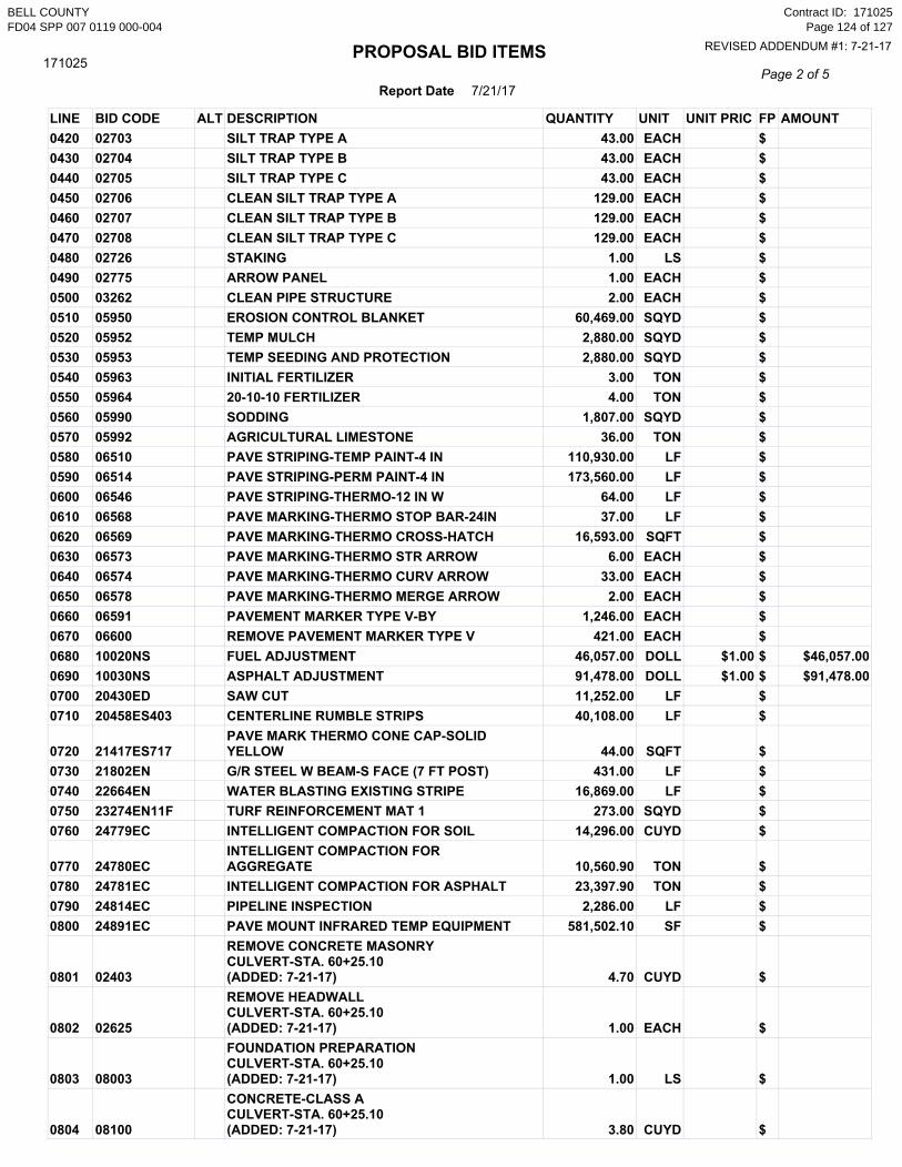
171025
LINE BID CODE ALT DESCRIPTION QUANTITY UNIT UNIT PRIC FP AMOUNT0420 02703 SILT TRAP TYPE A 43.00 EACH $0430 02704 SILT TRAP TYPE B 43.00 EACH $0440 02705 SILT TRAP TYPE C 43.00 EACH $0450 02706 CLEAN SILT TRAP TYPE A 129.00 EACH $0460 02707 CLEAN SILT TRAP TYPE B 129.00 EACH $0470 02708 CLEAN SILT TRAP TYPE C 129.00 EACH $0480 02726 STAKING 1.00 LS $0490 02775 ARROW PANEL 1.00 EACH $0500 03262 CLEAN PIPE STRUCTURE 2.00 EACH $0510 05950 EROSION CONTROL BLANKET 60,469.00 SQYD $0520 05952 TEMP MULCH 2,880.00 SQYD $0530 05953 TEMP SEEDING AND PROTECTION 2,880.00 SQYD $0540 05963 INITIAL FERTILIZER 3.00 TON $0550 05964 20-10-10 FERTILIZER 4.00 TON $0560 05990 SODDING 1,807.00 SQYD $0570 05992 AGRICULTURAL LIMESTONE 36.00 TON $0580 06510 PAVE STRIPING-TEMP PAINT-4 IN 110,930.00 LF $0590 06514 PAVE STRIPING-PERM PAINT-4 IN 173,560.00 LF $0600 06546 PAVE STRIPING-THERMO-12 IN W 64.00 LF $0610 06568 PAVE MARKING-THERMO STOP BAR-24IN 37.00 LF $0620 06569 PAVE MARKING-THERMO CROSS-HATCH 16,593.00 SQFT $0630 06573 PAVE MARKING-THERMO STR ARROW 6.00 EACH $0640 06574 PAVE MARKING-THERMO CURV ARROW 33.00 EACH $0650 06578 PAVE MARKING-THERMO MERGE ARROW 2.00 EACH $0660 06591 PAVEMENT MARKER TYPE V-BY 1,246.00 EACH $0670 06600 REMOVE PAVEMENT MARKER TYPE V 421.00 EACH $0680 10020NS FUEL ADJUSTMENT 46,057.00 DOLL $1.00 $ $46,057.000690 10030NS ASPHALT ADJUSTMENT 91,478.00 DOLL $1.00 $ $91,478.000700 20430ED SAW CUT 11,252.00 LF $0710 20458ES403 CENTERLINE RUMBLE STRIPS 40,108.00 LF $
0720 21417ES717PAVE MARK THERMO CONE CAP-SOLIDYELLOW 44.00 SQFT $
0730 21802EN G/R STEEL W BEAM-S FACE (7 FT POST) 431.00 LF $0740 22664EN WATER BLASTING EXISTING STRIPE 16,869.00 LF $0750 23274EN11F TURF REINFORCEMENT MAT 1 273.00 SQYD $0760 24779EC INTELLIGENT COMPACTION FOR SOIL 14,296.00 CUYD $
0770 24780ECINTELLIGENT COMPACTION FORAGGREGATE 10,560.90 TON $
0780 24781EC INTELLIGENT COMPACTION FOR ASPHALT 23,397.90 TON $0790 24814EC PIPELINE INSPECTION 2,286.00 LF $0800 24891EC PAVE MOUNT INFRARED TEMP EQUIPMENT 581,502.10 SF $
0801 02403
REMOVE CONCRETE MASONRYCULVERT-STA. 60+25.10(ADDED: 7-21-17) 4.70 CUYD $
0802 02625
REMOVE HEADWALLCULVERT-STA. 60+25.10(ADDED: 7-21-17) 1.00 EACH $
0803 08003
FOUNDATION PREPARATIONCULVERT-STA. 60+25.10(ADDED: 7-21-17) 1.00 LS $
0804 08100
CONCRETE-CLASS ACULVERT-STA. 60+25.10(ADDED: 7-21-17) 3.80 CUYD $
BELL COUNTYFD04 SPP 007 0119 000-004
Contract ID: 171025Page 124 of 127
REVISED ADDENDUM #1: 7-21-17

PROPOSAL BID ITEMS
Report Date 7/21/17Page 3 of 5
171025
LINE BID CODE ALT DESCRIPTION QUANTITY UNIT UNIT PRIC FP AMOUNT
0805 08150
STEEL REINFORCEMENTCULVERT-STA. 60+25.10(ADDED: 7-21-17) 356.00 LB $
Section: 0003 - DRAINAGELINE BID CODE ALT DESCRIPTION QUANTITY UNIT UNIT PRIC FP AMOUNT0810 00440 ENTRANCE PIPE-15 IN 322.00 LF $0820 00441 ENTRANCE PIPE-18 IN 46.00 LF $0830 00443 ENTRANCE PIPE-24 IN 87.00 LF $0840 00462 CULVERT PIPE-18 IN 87.00 LF $0850 00464 CULVERT PIPE-24 IN 104.00 LF $0860 00469 CULVERT PIPE-42 IN 90.00 LF $0870 00521 STORM SEWER PIPE-15 IN 94.00 LF $0880 00522 STORM SEWER PIPE-18 IN 1,602.00 LF $0890 00524 STORM SEWER PIPE-24 IN 4.00 LF $0900 00528 STORM SEWER PIPE-36 IN 27.00 LF $0910 00534 STORM SEWER PIPE-72 IN 93.00 LF $0920 01204 PIPE CULVERT HEADWALL-18 IN 3.00 EACH $0930 01208 PIPE CULVERT HEADWALL-24 IN 2.00 EACH $0940 01212 PIPE CULVERT HEADWALL-36 IN 1.00 EACH $0950 01214 PIPE CULVERT HEADWALL-42 IN 2.00 EACH $0960 01433 SLOPED BOX OUTLET TYPE 1-18 IN 2.00 EACH $0970 01450 S & F BOX INLET-OUTLET-18 IN 1.00 EACH $0980 01451 S & F BOX INLET-OUTLET-24 IN 1.00 EACH $0990 01456 CURB BOX INLET TYPE A 14.00 EACH $1000 01493 DROP BOX INLET TYPE 2 1.00 EACH $1010 01496 DROP BOX INLET TYPE 3 2.00 EACH $1020 01544 DROP BOX INLET TYPE 11 2.00 EACH $1030 01641 JUNCTION BOX-15 IN 1.00 EACH $1040 01642 JUNCTION BOX-18 IN 1.00 EACH $1050 01645 JUNCTION BOX-36 IN 2.00 EACH $1060 01767 MANHOLE TYPE C 1.00 EACH $1070 24025EC PIPE CULVERT HEADWALL-72 IN 1.00 EACH $
Section: 0004 - BRIDGE-CULVERT-27096LINE BID CODE ALT DESCRIPTION QUANTITY UNIT UNIT PRIC FP AMOUNT1080 02625 REMOVE HEADWALL 1.00 EACH $1090 08002 STRUCTURE EXCAV-SOLID ROCK 16.00 CUYD $1100 08003 FOUNDATION PREPARATION 1.00 LS $1110 08100 CONCRETE-CLASS A 38.40 CUYD $1120 08150 STEEL REINFORCEMENT 3,628.00 LB $
Section: 0005 - BRIDGE-CULVERT-27257LINE BID CODE ALT DESCRIPTION QUANTITY UNIT UNIT PRIC FP AMOUNT
BELL COUNTYFD04 SPP 007 0119 000-004
Contract ID: 171025Page 125 of 127
REVISED ADDENDUM #1: 7-21-17

PROPOSAL BID ITEMS
Report Date 7/21/17Page 4 of 5
171025
LINE BID CODE ALT DESCRIPTION QUANTITY UNIT UNIT PRIC FP AMOUNT1130 02625 REMOVE HEADWALL 1.00 EACH $1140 08002 STRUCTURE EXCAV-SOLID ROCK 20.00 CUYD $1150 08003 FOUNDATION PREPARATION 1.00 LS $1160 08100 CONCRETE-CLASS A 45.40 CUYD $1170 08150 STEEL REINFORCEMENT 6,144.00 LB $
Section: 0006 - WATERLINE - SECTION B1LINE BID CODE ALT DESCRIPTION QUANTITY UNIT UNIT PRIC FP AMOUNT1180 14003 W CAP EXISTING MAIN 2.00 EACH $1190 14005 W ENCASEMENT CONCRETE 55.00 LF $1200 14012 W ENCASEMENT STEEL OPEN CUT RANGE 1 170.00 LF $1210 14013 W ENCASEMENT STEEL OPEN CUT RANGE 2 110.00 LF $1220 14019 W FIRE HYDRANT ASSEMBLY 1.00 EACH $1230 14021 W FIRE HYDRANT REMOVE 1.00 EACH $1240 14022 W FLUSH HYDRANT ASSEMBLY 3.00 EACH $1250 14028 W METER 3/4 INCH 23.00 EACH $1260 14067 W PIPE POLYETHYLENE/PLASTIC 03 INCH 119.00 LF $1270 14070 W PIPE POLYETHYLENE/PLASTIC 08 INCH 3,967.00 LF $1280 14073 W PIPE POLYETHYLENE/PLASTIC SPECIAL 690.00 LF $1290 14089 W TAPPING SLEEVE AND VALVE SIZE 1 1.00 EACH $1300 14095 W TIE-IN 08 INCH 2.00 EACH $1310 14101 W TIE-IN SPECIAL 49.00 EACH $1320 14102 W VALVE 02 INCH 2.00 EACH $1330 14103 W VALVE 03 INCH 1.00 EACH $1340 14106 W VALVE 08 INCH 2.00 EACH $1350 14148 W SERV COPPER LONG SIDE 3/4 IN 1.00 EACH $1360 14152 W SERV COPPER SHORT SIDE 3/4 IN 48.00 EACH $
Section: 0007 - WATERLINE - SECTION B2LINE BID CODE ALT DESCRIPTION QUANTITY UNIT UNIT PRIC FP AMOUNT
1370 14003W CAP EXISTING MAIN(3-IN) 1.00 EACH $
1380 14003W CAP EXISTING MAIN(6-IN) 1.00 EACH $
1390 14003W CAP EXISTING MAIN(8-IN) 1.00 EACH $
1400 14005 W ENCASEMENT CONCRETE 140.00 LF $1410 14014 W ENCASEMENT STEEL OPEN CUT RANGE 3 40.00 LF $1420 14015 W ENCASEMENT STEEL OPEN CUT RANGE 4 100.00 LF $1430 14025 W METER 1 INCH 2.00 EACH $1440 14028 W METER 3/4 INCH 9.00 EACH $1450 14069 W PIPE POLYETHYLENE/PLASTIC 06 INCH 52.00 LF $1460 14070 W PIPE POLYETHYLENE/PLASTIC 08 INCH 2,163.00 LF $1470 14089 W TAPPING SLEEVE AND VALVE SIZE 1 1.00 EACH $1480 14092 W TIE-IN 03 INCH 1.00 EACH $1490 14095 W TIE-IN 08 INCH 2.00 EACH $
BELL COUNTYFD04 SPP 007 0119 000-004
Contract ID: 171025Page 126 of 127
REVISED ADDENDUM #1: 7-21-17

PROPOSAL BID ITEMS
Report Date 7/21/17Page 5 of 5
171025
LINE BID CODE ALT DESCRIPTION QUANTITY UNIT UNIT PRIC FP AMOUNT
1500 14101W TIE-IN SPECIAL(RECONNECT 1-IN WATER SERVICE) 2.00 EACH $
1510 14101W TIE-IN SPECIAL(RECONNECT 3/4-IN WATER SERVICE) 9.00 EACH $
1520 14105 W VALVE 06 INCH 1.00 EACH $1530 14106 W VALVE 08 INCH 2.00 EACH $1540 14148 W SERV COPPER LONG SIDE 3/4 IN 1.00 EACH $1550 14149 W SERV COPPER SHORT SIDE 1 IN 2.00 EACH $1560 14152 W SERV COPPER SHORT SIDE 3/4 IN 8.00 EACH $
Section: 0008 - DEMOBILIZATION &/OR MOBILIZATIONLINE BID CODE ALT DESCRIPTION QUANTITY UNIT UNIT PRIC FP AMOUNT1570 02568 MOBILIZATION 1.00 LS $1580 02569 DEMOBILIZATION 1.00 LS $
BELL COUNTYFD04 SPP 007 0119 000-004
Contract ID: 171025Page 127 of 127
REVISED ADDENDUM #1: 7-21-17

SPECIAL NOTE FOR PAVER MOUNTED TEMPERATURE PROFILES
This Special Note will apply when indicated on the plans or in the proposal. Section references herein are to the
Department’s Standard Specifications for Road and Bridge Construction current edition.
1.01.01.01.0 DDDDESCRIPTIONESCRIPTIONESCRIPTIONESCRIPTION. . . . Provide a paver mounted infrared temperature equipment to continually monitor the
temperature of the asphalt mat immediately behind all paver(s) during the placement operations for all driving lanes
within the project limits. Provide thermal profiles that include material temperature and measurement locations.
2.02.02.02.0 MATERIALS AND EQUIPMENT.MATERIALS AND EQUIPMENT.MATERIALS AND EQUIPMENT.MATERIALS AND EQUIPMENT. In addition to the equipment specified in Subsection 403.02 Utilize a thermal
equipment supplier that can provide a qualified representative for on-site technical assistance during the initial setup,
pre-construction verification, and data management and processing as needed during the Project to maintain
equipment within specifications and requirements.
Provide operator settings, user manuals, required viewing/export software for analysis. Ensure the temperature
equipment will meet the following:
(A) A device with one or more infrared sensors that is capable of measuring in at least 1 foot intervals across
the paving width, with a minimum width of 12 feet, or extending to the recording limits of the equipment,
whichever is greater. A Maximum of two (2)Maximum of two (2)Maximum of two (2)Maximum of two (2) brackets are allowed in the influence area under the sensors. A
temperature profile must be made on at least 1 foot intervals longitudinally down the road:
(B) Infrared sensor(s):
(1) Measuring from 32°F to 400°F with an accuracy of ± 2.0% of the sensor reading.
(C) Ability to measure the following:
(1) The placement distance using a Global Positioning System (GPS) or a Distance Measuring
Instrument (DMI) and a Global Positioning System (GPS).
(2) Stationing
(D) GPS: Accuracy ± 4 feet in the X and Y Direction
(E) Latest version of software to collect, display, retain and analyze the mat temperature readings during
placement. The software must have the ability to create and analyze:
(1) Full collected width of the thermal profiles,
(2) Paver speed and
(3) Paver stops and duration for the entire Project.
(F) Ability to export data automatically to a remote data server (“the cloud”).
At the preconstruction meeting, provide the Department with rights to allow for web access to the data file location.
This web-based software must also provide the Department with the ability to download the raw files and software
and to convert them into the correct format.
(G) The thermal profile data files must provide the following data in a neat easy to read table format.
(1) Project information including Road Name and Number, PCN, Beginning and Ending MPs.
(2) IR Bar Manufacturer and Model number
(3) Number of Temperature Sensors (N)
(4) Spacing between sensors and height of sensors above the asphalt mat
(5) Total number of individual records taken each day (DATA BLOCK)
(a) Date and Time reading taken
(b) Latitude and Longitude
(c) Distance paver has moved from last test location
(d) Direction and speed of the paver
(e) Surface temperature of each of the sensors
3333.0.0.0.0 CONSTRUCTION. CONSTRUCTION. CONSTRUCTION. CONSTRUCTION. Provide the Engineer with all required documentation at the pre-construction conference.
BELL COUNTY FD04 SPP 007 0119 000-004
ADDED ADDENDUM #1: 7-21-17 Contract ID: 171025
Page 1 of 2

(A) Install and operate equipment in accordance with the manufacturer’s specifications.
(B) Verify that the temperature sensors are within ± 2.0% using an independent temperature device on a
material of known temperature. Collect and compare the GPS coordinates from the equipment with an
independent measuring device.
(1) Ensure the independent survey grade GPS measurement device is calibrated to the correct
coordinate system (using a control point), prior to using these coordinates to validate the equipment GPS.
(2) The comparison is considered acceptable if the coordinates are within 4 feet of each other in
the X and Y direction.
(C) Collect thermal profiles on all Driving Lanes during the paving operation and transfer the data to the
“cloud” network or if automatic data transmission is not available, transfer the data to the Engineer at the
end of daily paving.
(D) Contact the Department immediately when System Failure occurs. Daily Percent Coverage will be
considered zero when the repairs are not completed within two (2) working days of System Failure. The start
of this two (2) working day period begins the next working day after System Failure.
(E) Evaluate thermal profile segments, every 150 feet, and summarize the segregation of temperature
results. Results are to be labeled as Minimal 0°-25°F, Moderate 25.1°-50°F and Severe >50°. Severe readings
over 3 consecutive segments or over 4 or more segments in a day warrant investigation on the cause of the
differential temperature distribution.
4.04.04.04.0 MEASUREMENT. MEASUREMENT. MEASUREMENT. MEASUREMENT. The Department will measure the total area of the driving lanes mapped by the infrared
scanners. Full payment will be provided for all driving lanes with greater than 85% coverage. Partial payment will be
made for all areas covered from 50% coverage to 85% coverage at the following rate Coverage area percentage X
Total bid amount. And area with less than 50% coverage will not be measured for payment.
5.05.05.05.0 PAYMENT. PAYMENT. PAYMENT. PAYMENT. The Department will make payment for the completed and accepted quantities under the
following:
1. Payment is full compensation for all work associated with providing all required equipment, training, and
documentation.
2. Delays due to GPS satellite reception of signals or equipment breakdowns will not be considered justification
for contract modifications or contract extensions.
Code Pay Item Pay Unit
24891EC PAVE MOUNT INFRARED TEMP EQUIPMENT SQFT
BELL COUNTY FD04 SPP 007 0119 000-004
ADDED ADDENDUM #1: 7-21-17 Contract ID: 171025
Page 2 of 2