Embed Size (px)
Citation preview
Novel Tools and Methods
Machine Learning-Based Pipette PositionalCorrection for Automatic Patch Clamp In VitroMercedes M. Gonzalez, Colby F. Lewallen, Mighten C. Yip, and Craig R. Forest
https://doi.org/10.1523/ENEURO.0051-21.2021
Georgia Institute of Technology, George W. Woodruff School of Mechanical Engineering, Atlanta, GA 30332
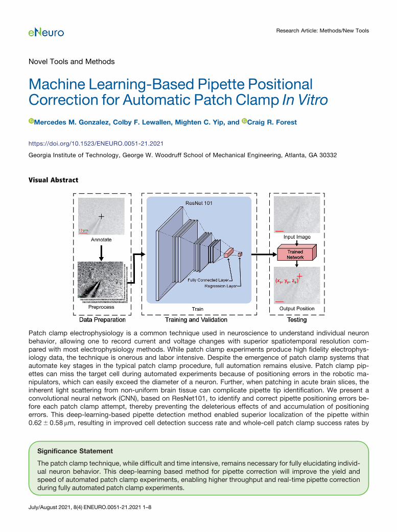
Visual Abstract
Patch clamp electrophysiology is a common technique used in neuroscience to understand individual neuronbehavior, allowing one to record current and voltage changes with superior spatiotemporal resolution com-pared with most electrophysiology methods. While patch clamp experiments produce high fidelity electrophys-iology data, the technique is onerous and labor intensive. Despite the emergence of patch clamp systems thatautomate key stages in the typical patch clamp procedure, full automation remains elusive. Patch clamp pip-ettes can miss the target cell during automated experiments because of positioning errors in the robotic ma-nipulators, which can easily exceed the diameter of a neuron. Further, when patching in acute brain slices, theinherent light scattering from non-uniform brain tissue can complicate pipette tip identification. We present aconvolutional neural network (CNN), based on ResNet101, to identify and correct pipette positioning errors be-fore each patch clamp attempt, thereby preventing the deleterious effects of and accumulation of positioningerrors. This deep-learning-based pipette detection method enabled superior localization of the pipette within0.626 0.58 mm, resulting in improved cell detection success rate and whole-cell patch clamp success rates by
Significance Statement
The patch clamp technique, while difficult and time intensive, remains necessary for fully elucidating individ-ual neuron behavior. This deep-learning based method for pipette correction will improve the yield andspeed of automated patch clamp experiments, enabling higher throughput and real-time pipette correctionduring fully automated patch clamp experiments.
July/August 2021, 8(4) ENEURO.0051-21.2021 1–8
Research Article: Methods/New Tools
71% and 59%, respectively, compared with the state-of-the-art cross-correlation method. Furthermore, thistechnique reduced the average time for pipette correction by 81%. This technique enables real-time correctionof pipette position during patch clamp experiments with similar accuracy and quality of recording to manualpatch clamp, making notable progress toward full human-out-of-the-loop automation for patch clampelectrophysiology.
Key words: automated; CNN; deep learning; electrophysiology; machine learning; patch clamp
IntroductionCharacterizing neuronal function on a single cell level is
crucial to unraveling the biological mechanisms underlyingbrain activity. One of the most important techniques used inneuroscience to understand individual neuron behavior ispatch clamp electrophysiology. This Nobel prize-winningtechnique allows one to record subthreshold current and volt-age changes, enabling scientists to better understand neuro-nal communication. While optical methods offer a promisingnon-invasive method to study single neurons (Hochbaum etal., 2014; Kiskinis et al., 2018; Adam et al., 2019; Fan et al.,2020), their reliance on relative measurements rather than ab-solute voltage or current and suboptimal spatiotemporal re-solution still require patch clamp to validate recordings ofindividual cellular behavior.Typically, an in vitro patch clamp experiment is per-
formed as follows: one views a brain slice under a micro-scope, manually maneuvers and delicately places a 1- to2-mm tip of a glass pipette into contact with a 10-mm di-ameter cell membrane, creates a high-resistance seal be-tween the pipette and cell membrane, and breaks into thecell to create a whole-cell configuration. This technique isimmensely time intensive even for a skilled expert underoptimal conditions. To improve the throughput and yieldof these essential yet challenging experiments, severalgroups have invented automated patch clamp rigs forboth in vitro (Wu et al., 2016; Kolb et al., 2019; Lewallen etal., 2019) and in vivo (Kodandaramaiah et al., 2012; Kolbet al., 2013; Annecchino et al., 2017; Stoy et al., 2017;Suk et al., 2017; Holst et al., 2019) electrophysiology, in-cluding a handful of techniques developed specifically for
automated pipette localization (Long et al., 2015; Koos etal., 2017, 2021) and cell tracking (Lee et al., 2018).One of the most challenging steps to automate in these
rigs is the accurate and repeatable placement of the pip-ette tip close to the membrane of a cell (Long et al., 2015).Conventionally, patch pipettes are controlled by micro-manipulators that have random and systematic errors onthe order of 10mm (Kolb et al., 2019) when repeatedlymoving to and from the same location. A major drawbackfor previous pipette tip localization techniques (Long etal., 2015; Koos et al., 2017, 2021) is that the accuracy issignificantly reduced when real-world background lightingvariation and noise is introduced. Light scattering fromthe brain tissue induces significant noise in the image andrenders these methods practically useless since they relyon a clear image of the pipette in acute slice experiments,despite their success in cultured cell experiments. Toovercome this obstacle, we implemented a convolutionalneural network (CNN), ResNet101, to automatically iden-tify and correct the pipette tip localization error for auto-mated in vitro patch clamp experiments. This method willnot only improve the precise placement of the pipettenear the cell membrane, but also reduce the time requiredto localize the pipette tip over a cell and therefore improvethe overall throughput and efficiency of the automatedpatch clamp process.
Materials and MethodsCoordinate system and definition of errorsTo accurately identify the pipette location for patch
clamp experiments, we defined a coordinate system rela-tive to the objective location so that the center of the fieldof view, with the pipette tip in focus, was considered theorigin. Hereafter, the view of the brain slice under the mi-croscope will be referred to as the xy-plane. The z direc-tion is defined by the vertical distance perpendicular tothat plane, with z = 0 at the location where the pipette wasperfectly in focus.There were three types of positioning errors addressed,
as shown in Figure 1A. When moving the pipette, the pip-ette is commanded to move to the desired position(white), typically coincident with the center of a cell (x,y)cellin automated patch clamp experiments. Because of ran-dom and systematic errors in the three-axis manipulators,the true pipette position (blue) is not equal to the desiredposition, resulting in the true pipette error (~tx ; ~ty ; ~tz ). Wecan estimate the true position of the pipette with the CNN,resulting in the computed CNN position (red). This CNNposition has CNN error vector (~cx ; ~cy ; ~cz ), defined by thedifference between the true pipette position and the CNNposition. Since we cannot determine the true pipette
Received February 2, 2021; accepted May 5, 2021; First published July 22,2021.M.C.Y. is receiving financial compensation for his work with Neuromatic
Devices. All other authors declare no competing financial interests.Author contributions: M.M.G., C.F.L., M.C.Y., and C.R.F. designed research;
M.M.G., C.F.L., and M.C.Y. performed research; M.M.G., C.F.L., M.C.Y., andC.R.F. analyzed data; M.M.G. wrote the paper.This work was supported by the National Institutes of Health (NIH) BRAIN
Initiative Grant (National Eye Institute and National Institute of Mental HealthGrant 1-U01-MH106027-01), the NIH Grant R01NS102727, the NIH Single CellGrant 1 R01 EY023173, National Science Foundation Grants EHR 0965945and CISE 1110947, and the NIH Grant R01DA029639.Acknowledgements: We thank Dr. Matthew Rowan for insightful feedback
on figures and data analysis.Correspondence should be addressed to Mercedes M. Gonzalez at m.
[email protected]://doi.org/10.1523/ENEURO.0051-21.2021
Copyright © 2021 Gonzalez et al.
This is an open-access article distributed under the terms of the CreativeCommons Attribution 4.0 International license, which permits unrestricted use,distribution and reproduction in any medium provided that the original work isproperly attributed.
Research Article: Methods/New Tools 2 of 8
July/August 2021, 8(4) ENEURO.0051-21.2021 eNeuro.org
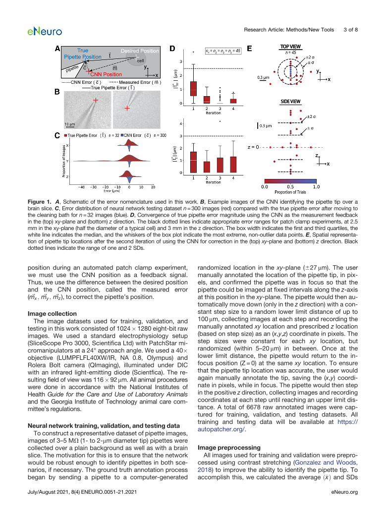
position during an automated patch clamp experiment,we must use the CNN position as a feedback signal.Thus, we use the difference between the desired positionand the CNN position, called the measured error( ~mx ; ~my ; ~mz ), to correct the pipette’s position.
Image collectionThe image datasets used for training, validation, and
testing in this work consisted of 1024� 1280 eight-bit rawimages. We used a standard electrophysiology setup(SliceScope Pro 3000, Scientifica Ltd) with PatchStar mi-cromanipulators at a 24° approach angle. We used a 40�objective (LUMPFLFL40XW/IR, NA 0.8, Olympus) andRolera Bolt camera (QImaging), illuminated under DICwith an infrared light-emitting diode (Scientfica). The re-sulting field of view was 116� 92mm. All animal procedureswere done in accordance with the National Institutes ofHealth Guide for the Care and Use of Laboratory Animalsand the Georgia Institute of Technology animal care com-mittee’s regulations.
Neural network training, validation, and testing dataTo construct a representative dataset of pipette images,
images of 3–5 MV (1- to 2-mm diameter tip) pipettes werecollected over a plain background as well as with a brainslice. The motivation for this is to ensure that the networkwould be robust enough to identify pipettes in both sce-narios, if necessary. The ground truth annotation processbegan by sending a pipette to a computer-generated
randomized location in the xy-plane (627 mm). The usermanually annotated the location of the pipette tip, in pix-els, and confirmed the pipette was in focus so that thepipette could be imaged at fixed intervals along the z-axisat this position in the xy-plane. The pipette would then au-tomatically move down (only in the z direction) with a con-stant step size to a random lower limit distance of up to100mm, collecting images at each step and recording themanually annotated xy location and prescribed z location(based on step size) as an (x,y,z) coordinate in pixels. Thestep sizes were constant for each xy location, butrandomized (within 5–20 mm) in between. Once at thelower limit distance, the pipette would return to the in-focus position (Z = 0) at the same xy location. To ensurethat the pipette tip location was accurate, the user wouldagain manually annotate the tip, saving the (x,y) coordi-nate in pixels, while in focus. The pipette would then stepin the positive z direction, collecting images and recordingcoordinates at each step until reaching an upper limit dis-tance. A total of 6678 raw annotated images were cap-tured for training, validation, and testing datasets. Alltraining and testing data will be available at https://autopatcher.org/.
Image preprocessingAll images used for training and validation were prepro-
cessed using contrast stretching (Gonzalez and Woods,2018) to improve the ability to identify the pipette tip. Toaccomplish this, we calculated the average ð�xÞ and SDs
Figure 1. A, Schematic of the error nomenclature used in this work. B, Example images of the CNN identifying the pipette tip over abrain slice. C, Error distribution of neural network testing dataset n=300 images (red) compared with the true pipette error after moving tothe cleaning bath for n=32 images (blue). D, Convergence of true pipette error magnitude using the CNN as the measurement feedbackin the (top) xy-plane and (bottom) z direction. The black dotted lines indicate appropriate error ranges for patch clamp experiments, at 2.5mm in the xy-plane (half the diameter of a typical cell) and 3 mm in the z direction. The box width indicates the first and third quartiles, thewhite line indicates the median, and the whiskers of the box plot indicate the most extreme, non-outlier data points. E, Spatial representa-tion of pipette tip locations after the second iteration of using the CNN for correction in the (top) xy-plane and (bottom) z direction. Blackdotted lines indicate the range of one and 2 SDs.
Research Article: Methods/New Tools 3 of 8
July/August 2021, 8(4) ENEURO.0051-21.2021 eNeuro.org
(s ) of the pixel intensities of each image and mapped theoriginal pixel values to the range defined by ð�x62sÞ foreach image individually. This mapping improved the con-trast by reducing the range of pixel intensities, therebymaking a smaller range of pixel intensities more. Any pixelintensity that was outside the range of [0,1] after mappingwas set to 0 or 1, respectively. The images were thencropped to a square from the center and downsized to224� 224 for use with the CNN. These images were thentransformed to artificially increase the training dataset,making the network more robust to different orientationsof the pipette. The images, and their corresponding pip-ette tip location annotations, were flipped horizontally,vertically, and both horizontally and vertically. These threeaugmentations resulted in a total training dataset of24,747 images and a validation dataset of 765 images.The test images underwent the same preprocessing, butno augmentations, resulting in a total of 300 test images.All preprocessing and network training was done usingMATLAB 2020a and all patch clamp experiments weredone with MATLAB and LabVIEW programs.
CNN trainingThe pretrained network model, ResNet101, was used
as the basis for this work. ResNet101 is a CNN, 101 layersdeep, that is trained for classification problems. The resid-ual network family is known for performing well in classifi-cation challenges because the depth of these CNNs leadto superior performance (Zhang et al., 2018). Here, wewanted to predict the (x,y,z) location of the pipette tipbased on an image. To accomplish this, we replaced thefinal three layers of the ResNet101 architecture with a fullyconnected layer and a regression layer (Lathuiliere et al.,2020). This allowed us to define the output as a continu-ous 3� 1 vector, corresponding to the (x,y,z) location ofthe pipette tip.The training options are summarized in Table 1. Of the
optimizers available in the MATLAB Deep LearningToolbox, the rmsprop (root mean square propagation) op-timizer, or loss function, has reported the greatest accu-racy (Vani and Rao, 2019). The mini batch size should bea power of 2 and maximized for accuracy (Goodfellow etal., 2016). While computer RAM availability was limitedduring training, we determined a mini batch size of 16 wassuitable for this application. The number of epochs wasdetermined experimentally, aiming to minimize root meansquared error (RMSE) during training while maximizingnumber of epochs to ensure sufficient adjusting of theCNN’s weights. It is convention to have a dynamic learn-ing rate, so the learn rate schedule was set to piecewise,where the learn rate began at the initial learn rate and mo-notonically decreased by the learn rate drop factor aftereach drop period (in epochs; Bengio, 2012). Bengio rec-ommended beginning with a large learning rate and re-ducing the rate if the training loss does not converge.After testing a few different initial learn rates and dropfactors, we found a suitable learn rate schedule to fol-low. The validation frequency and patience were set totheir default values as suggested by MATLAB (TheMathWorks, 2020). We used a Dell Precision 5540
(NVIDIA GeForce GTX 1080 GPU, Intel(R) Core(TM) i7-9850H CPU @ 2.60GHz, 32 GB RAM, Windows 10, 64-bit) to train, validate, and test the CNN. The validationdata were shuffled with each epoch to prevent the CNNfrom over-fitting to the training and validation sets.
CNN testingTo evaluate the accuracy of the CNN pipette tip identifica-
tion used with an iterative proportional feedback controller,we performed a series of experiments over acute brain sli-ces. Specifically, a LabVIEW program randomized the initialpipette location in the field of view (within 627mm in the xy-plane and6 6mm in the z direction). The range of trainingdata in the z direction was limited to 6mm since pipette lo-calization error both near the edges of the field of view andout of focus was not observed; thus, did not warrant the ex-cess training data. The CNN used the current image to de-termine the position of the pipette tip. From that CNNposition, the measured error vector was calculated from theorigin (center of the field of view, in focus) and used to cor-rect the pipette location back to the origin. The CNN-basedpipette tip identification algorithm was run recursively for apredetermined number of iterations (1–4). To determine thetrue pipette error after iterative correction, the pipette tipwas then manually moved to the origin and the change inthe manipulator position was saved as the true pipette error.
Patch clamp experimentsWe ran automated patch clamp experiments using a
standard electrophysiology rig with four PatchStar microma-nipulators on a universal motorized stage (Scientifica, Ltd).We used a peristaltic pump (120S/DV, Watson-Marlow) toperfuse the brain slices with buffer solution. The Multiclamp700b amplifier (Molecular Devices) and USB-6221 OEMdata acquisition board (National Instruments) to collect re-cordings. We used a pressure control box (NeuromaticDevices) to regulate internal pipette pressure as well as acustom machined chamber with a smaller side chamber forcleaning solution. We followed the cleaning protocol as sug-gested by Kolb et al. (2016); however, we did not includerinsing in the cleaning protocol because recent literaturefound that there is no impediment to the whole-cell yield orquality of recording (C. Landry, M. Yip, I. Kolb, WA. Stoy, M.M. Gonzalez, C.R. Forest, unpublished observation). Wecompared the state-of-the-art cross-correlation method for
Table 1: CNN training options
Training option SettingSolver rmspropMini batch size 16Max epochs 60Initial learn rate 1e-4Learn rate schedule PiecewiseLearn rate drop factor 0.09Learn rate drop period 10Validation frequency 50Validation patience InfExecution environment gpuShuffle Every epoch
Research Article: Methods/New Tools 4 of 8
July/August 2021, 8(4) ENEURO.0051-21.2021 eNeuro.org
pipette detection (Kolb et al., 2019) to the CNN method pre-sented here in two different sets of experiments. In order toremove extraneous confounding variables, none of thepatch clamp experiments included the cell tracking algo-rithm used by Kolb et al. (2019), so that any variation be-cause of cell tracking would not affect the success rates ofthe two pipette identification methods.
Code accessibilityThe code used to train and test the network is included
as Extended Data 1, and is also available at https://github.com/mmgxw3/pipetteFindingCNN.
Statistical analysisTo determine statistical significance in success rates,
we used the Fischer’s exact test. For the comparison be-tween groups, we used a one-way ANOVA test, and aTukey’s HSD test. To test for normality, we used a two-sided x2 test that combines skew and kurtosis to test fornormality (D’Agostino, 1971; D’Agostino and Pearson,1973).
ResultsValidation of pipette position identificationTo determine whether the network could accurately
identify the pipette tip position over a brain slice, wetested the network on a set of 300 test images, manuallyannotated with ground truth positions. Representativetest images of the pipette over a brain slice, with the CNNposition indicated in red, are shown in Figure 1B. It is cru-cial that the CNN errors, ~c, are smaller than the true pip-ette errors, ~t, that accumulate during an experiment toensure that the pipette position error will converge. Todemonstrate that the CNN errors,~c, are smaller and morerepeatable than the pipette errors from moving to thecleaning bath and back to the sample,~t, these two distri-butions along each axis are displayed in Figure 1C. Themean absolute errors and SDs of the CNN errors for eachof the axes are shown in Table 2.To ensure that the CNN successfully corrected the pip-
ette tip position, we evaluated the network’s ability toconverge using the previously described testing work-flow. The magnitude of the true pipette error after one tofour iterations in the xy-plane (j~txy j) and z direction (j~tz j) areplotted in Figure 1D. While there was a significant differ-ence between the first and second iterations (p=0.001Tukey’s HSD test), there was no statistical significant dif-ference between the second and third iterations in the xy-plane (p=0.49 Tukey’s HSD test). After the second cor-rection, 62% of the attempts were within 1 SD (60.31 mm)of the target location in the xy-plane (p=0.016 D’Agostino
test for normality, a = 0.05), and 86% of the attemptswere within 2 SDs (60.62 mm), as indicated by the circlesin Figure 1E. Since the network was able to correct thepipette tip to less than approximately half the diameter ofa typical cell (10mm) in the xy-plane with only two itera-tions of the CNN, we only corrected the pipette positiontwice for implementation in automated patch clamp ex-periments. The discretization that is apparent along the y-axis is the step size of the micromanipulators, indicatingwe are approaching the stepper motor encoder resolu-tion. In the z direction, 64% of attempts were within 1 SD(0.60mm) of the target location (p=0.026 D’Agostino testfor normality, a = 0.05) and 84% of the attempts werewithin 2 SDs (1.2mm), which is an acceptable range thatwe believed would not impair the ability of the pipette tofind and patch clamp a cell. The accuracy in the z direc-tion was less crucial since the approach method is to de-scend the pipette from 15mm above the cell.
Automated patch clamp experimentsWe compared the success rates of the CNN method
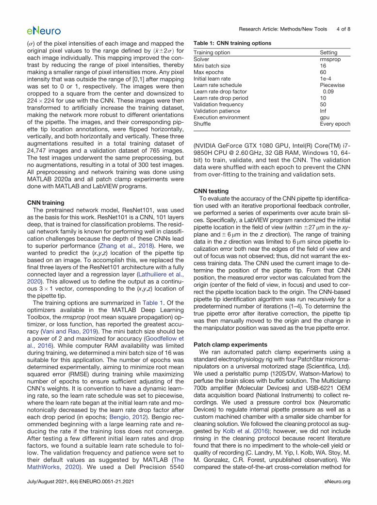
and the state-of-the-art cross-correlation method on pip-ette detection, cell detection, and whole-cell recording.Success rates are defined as a fraction of all attemptsusing the same pipette detection method, independent ofwhether the previous steps were successful. Success isdefined for each of the steps as follows: pipette detectionis considered successful when the pipette position can beidentified and corrected based on that identification. Celldetection is considered successful when the pipette re-sistance increases 0.2 MV over three consecutive de-scending 1-mm steps. Whole-cell patch clamp recordingis defined by successful cell detection, gigaseal, and
Table 2: CNN error from test dataset
Error ~c (mm) s (mm)cX 0.39 0.35cY 0.39 0.37cZ 0.83 0.88j~cj 1.13 0.88
Figure 2. Comparing (A) pipette detection, cell detection, andwhole-cell success rates and (B) time required for cross-corre-lation and CNN methods (n = 32 and = 36, respectively). Thebox width indicates the first and third quartiles, the white line in-dicates the median, and the whiskers of the box plot indicatethe most extreme, non-outlier data points. Using Fischer'sexact test; *p� 0.05, ***p�0.001.
Research Article: Methods/New Tools 5 of 8
July/August 2021, 8(4) ENEURO.0051-21.2021 eNeuro.org
break-in. When using the CNN method, two correctionswere done after the pipette is brought into the field ofview, as previously described. All experiments were doneover 5 d, using eight slices from five mice. The numbers ofattempts with each method are 32 and 36 for the cross-correlation and CNNmethods, respectively. These experi-ments were done independently, but prepared using thesame protocols and solutions to reduce variability in slicehealth.The pipette detection, cell detection, and whole-cell
success rates using cross-correlation were 66%, 59%,and 37%, respectively (n=32). The pipette detection, celldetection, and whole-cell success rates using the CNNwere 100%, 92%, and 64%, respectively (n=36). Theseresults are summarized in Figure 2A. A Fischer’s exacttest of the results indicate that the CNN improved the pip-ette detection success rate by 52% (p=8e-5 Fischer’sexact test), the cell detection success rate by 54%(p=0.001 Fischer’s exact test) and whole-cell successrate by 70% (p=0.05 Fischer’s exact test). Moreover, theCNNmethod could reliably identify the pipette position re-gardless of the background noise in the image within2.716 0.30 s, 81% faster than the average time of thecross-correlation method, as shown in Figure 2B.
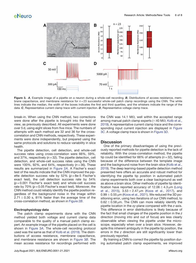
Electrophysiology dataThe patch clamp experiments done with the CNN
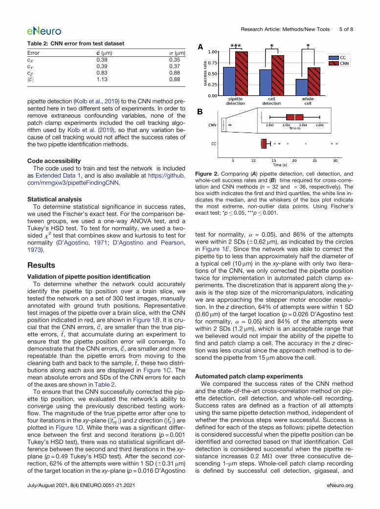
method yielded both voltage and current clamp datacomparable to the quality of a manual patch clamp ex-pert. An example image of the pipette placed on the cell isshown in Figure 3A. The whole-cell recording protocolused was the same as that of Kolb et al. (2019). The distri-butions of access resistance, membrane capacitance,and membrane resistance are shown in Figure 3B. Themean access resistance for recordings performed with
the CNN was 14.1 MV, well within the accepted rangeamong manual patch clamp experts (,40 MV; Kolb et al.,2019). A representative current clamp trace and the corre-sponding input current injection are displayed in Figure3C. A voltage clamp trace is shown in Figure 3D.
DiscussionOne of the primary disadvantages of using the previ-
ously reported methods for pipette detection is the lack ofreliability. With the cross-correlation method, the pipettetip could be identified for 66% of attempts (n=32), failingbecause of the difference between the template imageand the background noise from the brain slice (Kolb et al.,2019). The deep learning-based pipette detection methodpresented here offers an accurate and robust method foridentifying the pipette tip position in automated patchclamp experiments both over a clear background as wellas above a brain slice. Other methods of pipette tip identi-fication have reported accuracy of 12.066 4.3mm (Longet al., 2015), 3.536 2.47 mm (Koos et al., 2017), and0.9960.55 mm (Koos et al., 2021). We reduced the 3D po-sitioning error, using two iterations of our CNN method, to0.6260.58 mm. The CNN can more reliably identify thepipette location in the xy-plane compared with the z-axis.This difference in error distributions is likely because ofthe fact that small changes of the pipette position in the zdirection (moving into and out of focus) are less clearlyobservable when viewing the pipette under the micro-scope, especially when over a brain slice. However, de-spite this inherent ambiguity in the pipette tip position, theerrors in the z direction are still significantly lower thanpreviously reported.By training a CNN to correct the pipette tip position dur-
ing automated patch clamp experiments, we improved
Figure 3. A, Example image of a pipette on a neuron during a whole-cell recording. B, Distributions of access resistance, mem-brane capacitance, and membrane resistance for n=23 successful whole-cell patch clamp recordings using the CNN. The whitelines indicate the median, the width of the boxes indicates the first and third quartiles, and the whiskers indicate the range of thedata. C, Representative current clamp trace with current injection. D, Representative voltage clamp trace.
Research Article: Methods/New Tools 6 of 8
July/August 2021, 8(4) ENEURO.0051-21.2021 eNeuro.org
the success rates of pipette detection to 100% comparedwith the 66% success rate for cross-correlation. This abil-ity to reliably correct the pipette every time it is in the fieldof view could be used for automatic calibration or real-time tracking of the pipette’s location for optimization ofautopatching protocols. This method also improved thecell detection and whole-cell success rates by 54% and70%, respectively, compared with the success rates ofthe cross-correlation method without use of cell tracking,demonstrating the importance of the accuracy and ro-bustness of this crucial step in the autopatching process.Moreover, this CNN method without cell tracking per-formed similarly with cells 50–60 mm deep (64%) to that ofKolb et al. (2019; 60%), who reported a 60% whole-cellsuccess rate using cross-correlation and cell tracking atthe same cell depth (Kolb et al., 2019). Furthermore, theaverage time required to correct the pipette position usingthis CNN method is 81% less than the cross-correlationmethod, averaging 1.6 s per iteration of the CNN identifi-cation and movement of manipulators, opening doors toreal-time tracking of the pipette tip during automatedpatch clamp experiments.There were several limits to this study. For one, we only
used one micromanipulator manufacturer (Scientifica).While there may be different error distributions betweenvarious manufacturers, we anticipate that this methodwould still be effective if the modified ResNet101 archi-tecture was trained with new images specific to the objec-tive magnification and manipulator. Further, only pipetteswith resistances in the range 3–5 mm were used for train-ing and testing since this range is standard for patchclamp experiments in vitro. Pipettes used for other appli-cations, that are significantly narrower or wider, wouldneed more training data to ensure the network could reli-ably identify the tip’s new geometry. Moreover, use withother objectives would also require collecting new trainingdata. Finally, we omitted the use of cell tracking in the au-tomated patch clamp experiments so that we could iso-late errors and measure success rate independently ofthe cell tracking algorithm.Future work could use this CNN with cell tracking to si-
multaneously monitor and correct the pipette locationwith respect to the cell, potentially leading to even greaterwhole-cell success rates than previously reported.Moreover, this dual-monitoring could be used to continu-ously monitor the access resistance and correct the pip-ette position to maintain this resistance during longerduration experiments. Further, the combined monitoringof the cell and pipette positions may be of great use inmulti-electrode automated patch clamp experiments, inwhich the brain tissue moves more from the simultaneousmovement of multiple pipettes in the tissue. This workrepresents another significant step toward unmanned ro-botic patch clamp development.
References
Adam Y, Kim JJ, Lou S, Zhao Y, Xie ME, Brinks D, Wu H, Mostajo-Radji MA, Kheifets S, Parot V, Chettih S, Williams KJ, Gmeiner B,Farhi SL, Madisen L, Buchanan EK, Kinsella I, Zhou D, Paninski L,Harvey CD, et al. (2019) Voltage imaging and optogenetics reveal
behaviour-dependent changes in hippocampal dynamics. Nature569:413–417.
Annecchino LA, Morris AR, Copeland CS, Agabi OE, Chadderton P,Schultz SR (2017) Robotic automation of in vivo two-photon targetedwhole-cell patch-clamp electrophysiology. Neuron 95:1048–1055.e3.
Bengio Y (2012) Practical recommendations for gradient-basedtraining of deep architectures. In: Neural networks: tricks of thetrade, pp 437–478. New York: Springer, Berlin, Heidelberg.
D’Agostino RB (1971) An omnibus test of normality for moderate andlarge sample size. Biomatrika 58:341–348.
D’Agostino R, Pearson ES (1973) Tests for departure from normality.Biomatrika 60:613–622.
Fan LZ, Kheifets S, Böhm UL, Wu H, Piatkevich KD, Xie ME, Parot V,Ha Y, Evans KE, Boyden ES, Takesian AE, Cohen AE (2020) All-op-tical electrophysiology reveals the role of lateral inhibition in sen-sory processing in cortical layer 1. Cell 180:521–535.e18.
Gonzalez RC, Woods RE (2018) Digital image processing, Ed 4.London: Pearson Education Limited.
Goodfellow I, Bengio Y, Courville A (2016) Deep learning. Cambridge:TheMIT Press.
Hochbaum DR, Zhao Y, Farhi SL, Klapoetke N, Werley CA, KapoorV, Zou P, Kralj JM, MacLaurin D, Smedemark-Margulies N,Saulnier JL, Boulting GL, Straub C, Cho YK, Melkonian M, Ka ShuWong G, Jed Harrison D, Murthy VN, Sabatini BL, et al. (2014) All-optical electrophysiology in mammalian neurons using engineeredmicrobial rhodopsins. Nat Methods 11:825–833.
Holst GL, Stoy W, Yang B, Kolb I, Kodandaramaiah SB, Li L,Knoblich U, Zeng H, Haider B, Boyden ES, Forest CR (2019)Autonomous patch-clamp robot for functional characterization ofneurons in vivo: development and application to mouse visual cor-tex. J Neurophysiol 121:2341–2357.
Kiskinis E, Kralj JM, Zou P, Weinstein EN, Zhang H, Tsioras K,Wiskow O, Ortega JA, Eggan K, Cohen AE (2018) All-optical elec-trophysiology for high-throughput functional characterization of ahuman iPSC-derived motor neuron model of ALS. Stem CellReports 10:1991–2004.
Kodandaramaiah SB, Franzesi GT, Chow BY, Boyden ES, Forest CR(2012) Automated whole-cell patch-clamp electrophysiology ofneurons in vivo. Nat Methods 9:585–587.
Kolb I, Holst G, Goldstein B, Kodandaramaiah SB, Boyden ES,Culurciello E, Forest CR (2013) Automated, in-vivo, whole-cellelectrophysiology using an integrated patch-clamp amplifier. BMCNeurosci 14:P131.
Kolb I, Stoy WA, Rousseau EB, Moody OA, Jenkins A, Forest CR(2016) Cleaning patch-clamp pipettes for immediate reuse. SciRep 6:35001–35010.
Kolb I, Landry CR, Yip MC, Lewallen CF, Stoy WA, Lee J, Felouzis A,Yang B, Boyden ES, Rozell CJ, Forest CR (2019) PatcherBot: asingle-cell electrophysiology robot for adherent cells and brain sli-ces. J Neural Eng 16:e046003.
Koos K, Molnár J, Horváth P (2017) Pipette hunter: patch-clamp pip-ette detection. SCIA 2017:172–183.
Koos K, Oláh G, Balassa T, Mihut N, Rózsa M, Ozsvár A, Tasnadi E,Barzó P, Faragó N, Puskás L, Molnár G, Molnár J, Tamás G,Horvath P (2021) Automatic deep learning driven label-free imageguided patch clamp system for human and rodent in vitro slicephysiology. Nat Commun 12.
Lathuiliere S, Mesejo P, Alameda-Pineda X, Horaud R (2020) AComprehensive analysis of deep regression. IEEE Trans PatternAnal Mach Intell 42:2065–2081.
Lee J, Kolb I, Forest CR, Rozell CJ (2018) Cell membrane tracking inliving brain tissue using differential interference contrast micros-copy. IEEE Trans Image Process 27:1847–1861.
Lewallen CF, Wan Q, Maminishkis A, Stoy W, Kolb I, Hotaling N,Bharti K, Forest CR (2019) High-yield, automated intracellular elec-trophysiology in retinal pigment epithelia. J Neurosci Methods328:108442.
Long B, Li L, Knoblich U, Zeng H, Peng H (2015) 3D image-guidedautomatic pipette positioning for single cell experiments in vivo.Sci Rep 5:18426–18428.
Research Article: Methods/New Tools 7 of 8
July/August 2021, 8(4) ENEURO.0051-21.2021 eNeuro.org

Stoy WA, Kolb I, Holst GL, Liew Y, Pala A, Yang B, Boyden ES, StanleyGB, Forest CR (2017) Robotic navigation to subcortical neural tissue forintracellular electrophysiology in vivo. J Neurophysiol 118:1141–1150.
Suk HJ, vanWelie I, Kodandaramaiah SB, Allen B, Forest CR, Boyden ES(2017) Closed-loop real-time imaging enables fully automated cell-tar-geted patch-clamp neural recording in vivo. Neuron 95:1037–1047.e11.
The MathWorks (2020) Deep learning toolbox. Natick: The MathWorks.Available at https://www.mathworks.com/help/deeplearning/.
Vani S, Rao TVM (2019) An experimental approach towards the per-formance assessment of various optimizers on convolutional
neural network. Proceedings of the International Conference onTrends in Electronics and Informatics, ICOEI 2019, pp 331–336,Tirunelveli, India. IEEE.
Wu Q, Kolb I, Callahan BM, Su Z, Stoy W, Kodandaramaiah SB,Neve R, Zeng H, Boyden ES, Forest CR, Chubykin AA (2016)Integration of autopatching with automated pipette and celldetection in vitro. J Neurophysiol 116:1564–1578.
Zhang K, Sun M, Han TX, Yuan X, Guo L, Liu T (2018) Residual net-works of residual networks: multilevel residual networks. IEEETrans Circuits Syst Video Technol 28:1303–1314.
Research Article: Methods/New Tools 8 of 8
July/August 2021, 8(4) ENEURO.0051-21.2021 eNeuro.org