Embed Size (px)
Citation preview
Novel Multipath Mitigation Methods using a Dual-polarization Antenna
Paul D Groves, Ziyi Jiang, Benjamin Skelton, Paul A Cross University College London, United Kingdom
Lawrence Lau
Institut De Geomatica, Barcelona, Spain
Yacine Adane, Izzet Kale University of Westminster, London, United Kingdom
BIOGRAPHY Paul Groves is a Lecturer (academic faculty member) in GNSS, Navigation and Location Technology at University College London (UCL). He was a navigation systems researcher at QinetiQ from 1997 to 2009. He is interested in all aspects of navigation and positioning, including multi-sensor integrated navigation and robust GNSS under challenging reception conditions. He is an author of more than 30 technical publications, including the book, Principles of GNSS, Inertial and Multi-Sensor Integrated Navigation Systems (Artech House). He holds a BA/MA and a DPhil in physics from the University of Oxford. He is a Fellow of the Royal Institute of Navigation and chairs its R&D group. He is also an associate editor of Navigation: Journal of the ION. ([email protected]) Ziyi Jiang is a Research Fellow at UCL, currently specialising in multipath mitigation research. He has recently submitted his PhD thesis on digital route model aided integrated satellite navigation and low-cost inertial sensors for high-performance positioning on the railways. He holds a BEng in measuring and control technology from Harbin Engineering University, China. Benjamin Skelton is completing a MSc in surveying at UCL, including a research project studying dual-polarization GNSS antennas. He holds a LLB in Law from the University of Leicester, UK. He appears in Figure 3. Paul Cross is a visiting professor at UCL, having served as Professor of Geomatic Engineering from 1997 until his retirement in 2009. He obtained his PhD from the University of Nottingham in 1970 and has held teaching and research positions at the Universities of Nairobi, East London, Stuttgart and Newcastle. His main research interest is in precise GNSS positioning. Lawrence Lau is an Associate Professor in the Institute of Geomatics (IG) in Barcelona. Before joining IG, he was a Research Fellow in the Department of Civil, Environmental and Geomatic Engineering at UCL (September 2004 - February 2010). He received a PhD
from UCL in 2005. His current research is concerned with investigations into multipath modelling and its mitigation techniques, and high precision multiple-frequency GNSS data processing algorithms, especially for RTK and point positioning applications. Yacine Adane is a Research Fellow at the University of Westminster, specialising in radio frequency engineering. He received the Eng. degree in Electrical Engineering from the Science and Technology University, Algiers in 1999. He obtained his Master’s Degree in 2001 and his PhD in 2004 from the Pierre and Marie Curie University (Paris VI), Paris. During his PhD studies, based at France Télécom, he developed fast and efficient algorithms for near field evaluation of base station antennas. Since 2005, he has worked on various projects developing GNSS receivers and simulators. He has authored more than 20 papers on RF and antennas. He is the recipient of the best student paper award at the 2004 IEEE Mediterranean Microwave Symposium and co-recipient of the 2009 Innovation Lord Stafford Award. Izzet Kale is Professor of Applied Digital Signal Processing and Very-Large-Scale Integration at the University of Westminster and the director of Applied DSP and VLSI Research Group (ADVRG). He joined the staff of the University in 1984 and he has been with them since. He holds a BSc in electrical and electronic engineering from the Polytechnic of Central London an MSc in microelectronic systems from Edinburgh University and a PhD in techniques for reducing digital filter complexity from the University of Westminster. His research interests include the implementation of efficient low-power DSP algorithms for use in the positioning, communications and biomedical industries. ABSTRACT There are many methods for mitigating GNSS multipath errors. However, none of them completely eliminate the effects of multipath or suit all GNSS applications. A new class of multipath mitigation methods exploit new dual-polarization antenna technology. GNSS signals received
14023rd International Technical Meeting of the Satellite Division ofThe Institute of Navigation, Portland, OR, September 21-24, 2010
direct from the satellites have right-handed circular polarization (RHCP), whereas (singly) reflected signals have left-handed circular polarization (LHCP) or an elliptical polarization that may be expressed as the sum of RHCP and LHCP components. Conventional GNSS user antennas are more sensitive to signals with RHCP, attenuating LHCP signals and reducing, but not eliminating, the multipath errors in the receiver. An antenna with the opposite polarization sensitivity will attenuate the direct signals more than the reflected signals. This can be used to characterizing the reflected signals and thus mitigate the effects of multipath interference. Experimental work using an Antcom dual-polarization antenna and dual geodetic receivers is presented. This verifies that carrier power to noise density, C/N0, measurements obtained by separately correlating the RHCP and LHCP antenna outputs can be used to distinguish between a low-multipath and moderate-multipath environment. This may be used as the basis of a multipath detection technique. Three different multipath mitigation techniques that use a dual-polarization antenna are proposed. Measurement weighting estimates the code and carrier multipath error standard deviation from the RHCP-LHCP C/N0 difference and elevation angle. This is used by the navigation processor to discard and reweight measurements. Range-domain multipath correction, uses the pseudo-range, carrier-phase and C/N0 differences between the outputs of RHCP and LHCP receiver tracking channels, together with antenna calibration data, to estimate corrections to the code and carrier measurements. In tracking-domain multipath mitigation, the RHCP and LHCP correlator outputs are input to common acquisition and tracking algorithms which attempt to separate the direct line of sight and reflected signals The design of a novel dual-input GNSS front end, based on direct RF sampling, is presented This will be used, in conjunction with a software GNSS receiver, for future development and testing of multipath mitigation using a dual-polarization antenna. 1. INTRODUCTION Multipath interference is a significant limiting factor on the accuracy of GNSS for a host of applications, ranging from personal positioning in urban areas to precise land surveys. Reflected signals distort the code correlation peak within the receiver such that the code phase of the direct line-of-sight (LOS) signal can not be accurately determined by equalising the power in the early and late correlation channels. The resulting code tracking error depends on the receiver design as well as the direct and reflected signal strengths, path delay and phase difference, and can be up to half a chip [1] [2] [3]. Multipath interference also affects carrier phase determination, producing errors of up to
quarter of a wavelength. Multipath errors can be positive or negative, depending on the phase difference between the direct and reflected signals. A related phenomenon, sometimes wrongly classified as multipath, is non-line-of-sight (NLOS) signal reception. This occurs when the direct LOS signal is blocked and only reflected signals can be received. Pseudo-range measurement errors from NLOS signals are always positive and theoretically unlimited. A number of methods exist for mitigating the effects of multipath and NLOS propagation on code and carrier measurements. However, no method is applicable to all applications or eliminates multipath errors completely. This paper describes an emerging class of multipath mitigation methods that exploit new dual-polarization antenna technology. These may be used either alongside or in place of conventional multipath mitigation techniques. GNSS signals received direct from the satellites have right-handed circular polarization (RHCP), whereas (singly) reflected signals have left-handed circular polarization (LHCP) or an elliptical polarization that may be expressed as the sum of RHCP and LHCP components [4]. Conventional GNSS user antennas are more sensitive to signals with RHCP, attenuating LHCP signals and reducing, but not eliminating, the multipath errors in the receiver. An antenna with the opposite polarization sensitivity will attenuate the direct signals more than the reflected signals. For producing an accurate position solution, this is clearly undesirable. However, it is useful for detecting and characterizing the reflected signals. Dual-polarization GNSS antennas are now commercially available, combining coaxial RHCP-sensitive and LHCP-sensitive antennas in a single housing with dual outputs [5]. In the new multipath mitigation approach, the signals received from the two antennas are correlated separately within the receiver. The measurements are then compared in order to detect and calibrate the multipath errors. This paper begins with a review of existing multipath mitigation techniques and a summary of prior work with dual-polarization antennas. Section 2 then presents and discusses the results of initial multipath detection experiments with an Antcom dual-polarization antenna [5] and dual Leica 500-series geodetic GPS receivers. Section 3 proposes a number of multipath mitigation techniques using a dual-polarization antenna system. Section 4 then describes the development of a new dual-input GNSS RF front-end suitable for implementing the new multipath mitigation methods. Finally, Section 5 presents conclusions and discusses future work. Established multipath mitigation techniques can be classified into site-dependent, antenna-based, receiver-based and measurement-processing techniques. Starting with site-dependent methods, in-situ multipath
14123rd International Technical Meeting of the Satellite Division ofThe Institute of Navigation, Portland, OR, September 21-24, 2010
calibrations for reference stations may be made based on the repeatable satellite-reflector-antenna geometry in about one sidereal day [6] [7]. In multipath environmental modelling, a ray-tracing algorithm uses the known satellite-reflector-antenna geometry and physical properties of reflectors to determine the phase multipath errors [8]. Site-dependent techniques are highly effective at mitigating multipath, but are generally only suited to static receivers. A similar approach has been applied to mitigating multipath reflections off satellite bodies for attitude determination [9] [10]. Antenna-based multipath mitigation techniques include special antenna designs such as choke-ring antennas, Trimble’s Zephyr antennas and the multipath-limiting antenna for ground-based augmentation system reference stations [11]; these reduce the gain of signals reflected off the ground. Antenna array techniques, based on the geometric correlation of multipath errors at closely-spaced antennas, can be used for more general multipath mitigation [12] [13]. However, they perform best under simple multipath environments and are not suited to most kinematic applications because antenna arrays are usually bulky. A number of receiver-based techniques have been developed that mitigate code multipath errors by increasing the resolution of the code discriminator on the basis that the higher-frequency components of a GNSS signal are less impacted by moderate-delay multipath interference. The simplest approach is to use a narrow early-late correlator spacing [14], while a more sophisticated method is the Multipath Mitigation Window (MMW) [15]. Most of these techniques can effectively mitigate multipath where the path delay of the reflected component is more than 7.5 m, while the Vision Correlator will operate at path delays down to 5 m [16]. However, these two techniques operate at the expense of signal-to-noise ratio performance [17]. Moreover, they are not designed to mitigate the effects of multipath on carrier-phase measurements. The final class of multipath mitigation technique operate by processing the code and carrier measurements output by the receiver. One approach is to use stochastic models to weight measurements within the position solution according to their multipath vulnerability [18] [19] [20] [21] [22]. These models are based on the correlation between the carrier power-to-noise density, C/N0, and the multipath errors. For example, variations of the phase multipath error and resultant C/N0 over time are orthogonal [22]. The use of adaptive filters with spectrum analysis has been investigated for estimating phase multipath from C/N0 measurements. However, these techniques require sinusoidal multipath patterns to build up over time so are therefore only applicable for static and very low dynamic applications. A simple and effective method of reducing the effects of code multipath errors is smoothing the pseudo-range
measurements with carrier-phase. This is most effective where the time constant of the smoothing algorithm significantly exceeds the correlation time of the pseudo-range multipath errors. The final processor-based multipath mitigation technique is application of integrity monitoring techniques to identify multipath contaminated code and carrier measurements through their inconsistency with the uncontaminated measurements; this should work better with multiple constellation receivers. Multipath mitigation using dual-polarization antennas spans three categories: antenna-based, receiver-based and measurement-processing techniques. The use of dual RHCP and LHCP antennas for studying multipath was first proposed in [25] and results presented using a pair of helical antennas. Multipath mitigation using a dual-polarization antenna was demonstrated by simulation in [26]. In [4], multipath mitigation using arrays of dual-polarization antenna arrays was assessed by simulation. In [27], it was validated, using another multipath detection method, that the LHCP component of an Antcom dual-polarization antenna receives greater reflected signal power than the RHCP component. 2. MULTIPATH DETECTION EXPERIMENTS A series of tests were conducted to assess the ability of a dual-polarization antenna system to detect multipath interference. The focus was on comparing the carrier power to noise density, C/N0, measured from the LHCP and RHCP antenna outputs and assessing how this varied with elevation angle and multipath environment. Carrier power to noise density is a measure of the signal to noise ratio within the receiver’s correlators [1]. Following initial tests to determine the correct equipment configuration, experiments were conducted to characterise the behaviour of the system in a low-multipath environment (LME). Tests were then performed in a moderate multipath environment (MME) and the C/N0, measurements compared with those obtained in the LME. The hardware comprised an Antcom 3G1215RL-P-XS-1 dual-polarization L1/L2 GPS antenna, attached to a standard tribrach mount with dual amplifiers, as shown in Figure 1, together with a pair of Leica System SR530 geodetic GPS receivers, shown in Figure 2. One receiver was connected to each polarization output of the antenna via an amplifier powered from the receiver. Data was logged to memory cards independently with GPS itself used for time synchronisation between receivers. The Leica receivers would only log measurement data to the memory cards where sufficient signals were being received to generate a position solution. In the default high accuracy mode, it was typically only possible to track 1 or 2 satellites using the LHCP antenna output. However, switching the receivers to the higher sensitivity “MaxTrak” mode enabled 4 or more satellites to be tracked for most of the time in open and sparse urban
14223rd International Technical Meeting of the Satellite Division ofThe Institute of Navigation, Portland, OR, September 21-24, 2010
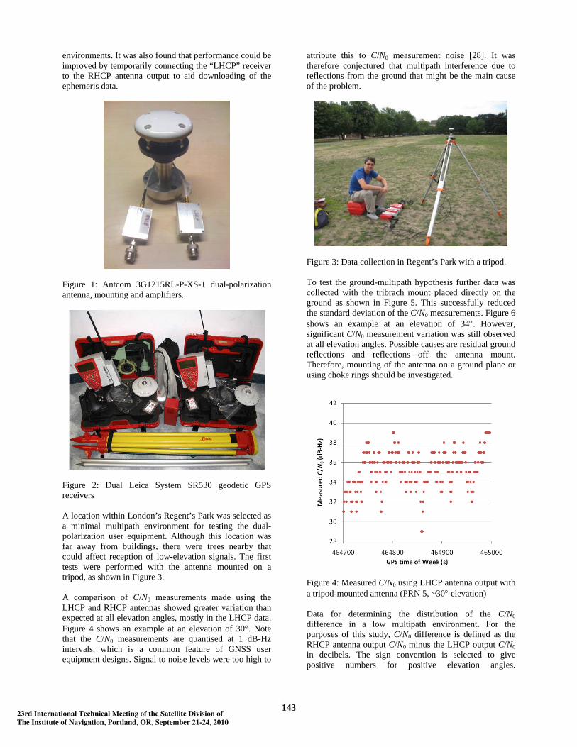
environments. It was also found that performance could be improved by temporarily connecting the “LHCP” receiver to the RHCP antenna output to aid downloading of the ephemeris data.
Figure 1: Antcom 3G1215RL-P-XS-1 dual-polarization antenna, mounting and amplifiers.
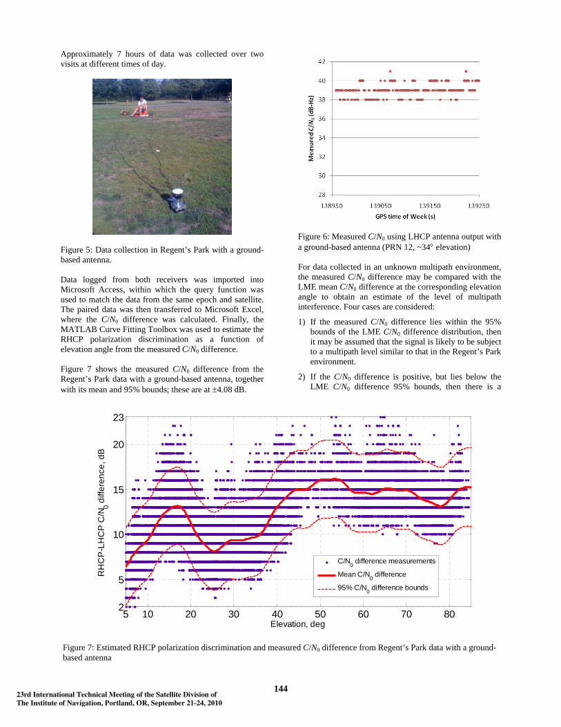
Figure 2: Dual Leica System SR530 geodetic GPS receivers A location within London’s Regent’s Park was selected as a minimal multipath environment for testing the dual-polarization user equipment. Although this location was far away from buildings, there were trees nearby that could affect reception of low-elevation signals. The first tests were performed with the antenna mounted on a tripod, as shown in Figure 3. A comparison of C/N0 measurements made using the LHCP and RHCP antennas showed greater variation than expected at all elevation angles, mostly in the LHCP data. Figure 4 shows an example at an elevation of 30°. Note that the C/N0 measurements are quantised at 1 dB-Hz intervals, which is a common feature of GNSS user equipment designs. Signal to noise levels were too high to
attribute this to C/N0 measurement noise [28]. It was therefore conjectured that multipath interference due to reflections from the ground that might be the main cause of the problem.
Figure 3: Data collection in Regent’s Park with a tripod. To test the ground-multipath hypothesis further data was collected with the tribrach mount placed directly on the ground as shown in Figure 5. This successfully reduced the standard deviation of the C/N0 measurements. Figure 6 shows an example at an elevation of 34°. However, significant C/N0 measurement variation was still observed at all elevation angles. Possible causes are residual ground reflections and reflections off the antenna mount. Therefore, mounting of the antenna on a ground plane or using choke rings should be investigated.
Figure 4: Measured C/N0 using LHCP antenna output with a tripod-mounted antenna (PRN 5, ~30° elevation) Data for determining the distribution of the C/N0 difference in a low multipath environment. For the purposes of this study, C/N0 difference is defined as the RHCP antenna output C/N0 minus the LHCP output C/N0 in decibels. The sign convention is selected to give positive numbers for positive elevation angles.
14323rd International Technical Meeting of the Satellite Division ofThe Institute of Navigation, Portland, OR, September 21-24, 2010
Approximately 7 hours of data was collected over two visits at different times of day.
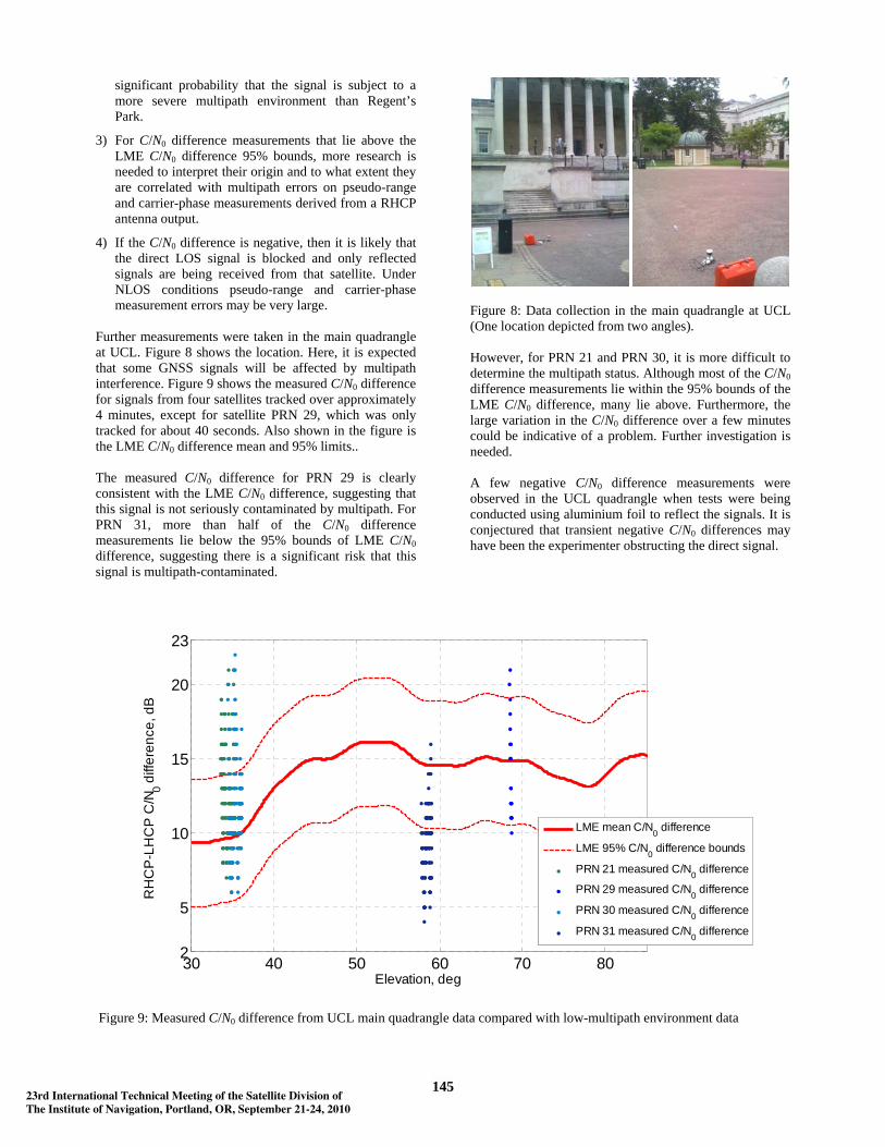
Figure 5: Data collection in Regent’s Park with a ground-based antenna. Data logged from both receivers was imported into Microsoft Access, within which the query function was used to match the data from the same epoch and satellite. The paired data was then transferred to Microsoft Excel, where the C/N0 difference was calculated. Finally, the MATLAB Curve Fitting Toolbox was used to estimate the RHCP polarization discrimination as a function of elevation angle from the measured C/N0 difference. Figure 7 shows the measured C/N0 difference from the Regent’s Park data with a ground-based antenna, together with its mean and 95% bounds; these are at ±4.08 dB.
Figure 6: Measured C/N0 using LHCP antenna output with a ground-based antenna (PRN 12, ~34° elevation) For data collected in an unknown multipath environment, the measured C/N0 difference may be compared with the LME mean C/N0 difference at the corresponding elevation angle to obtain an estimate of the level of multipath interference. Four cases are considered:
1) If the measured C/N0 difference lies within the 95% bounds of the LME C/N0 difference distribution, then it may be assumed that the signal is likely to be subject to a multipath level similar to that in the Regent’s Park environment.
2) If the C/N0 difference is positive, but lies below the LME C/N0 difference 95% bounds, then there is a
5 10 20 30 40 50 60 70 802
5
10
15
20
23
Elevation, deg
RH
CP
-LH
CP
C/N
0 diff
eren
ce, d
B
C/N0 difference measurements
Mean C/N0 difference
95% C/N0 difference bounds
Figure 7: Estimated RHCP polarization discrimination and measured C/N0 difference from Regent’s Park data with a ground-based antenna
14423rd International Technical Meeting of the Satellite Division ofThe Institute of Navigation, Portland, OR, September 21-24, 2010
significant probability that the signal is subject to a more severe multipath environment than Regent’s Park.
3) For C/N0 difference measurements that lie above the LME C/N0 difference 95% bounds, more research is needed to interpret their origin and to what extent they are correlated with multipath errors on pseudo-range and carrier-phase measurements derived from a RHCP antenna output.
4) If the C/N0 difference is negative, then it is likely that the direct LOS signal is blocked and only reflected signals are being received from that satellite. Under NLOS conditions pseudo-range and carrier-phase measurement errors may be very large.
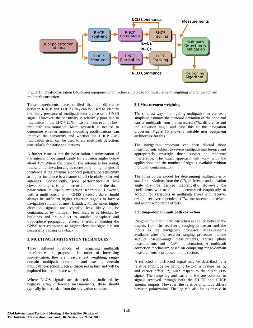
Further measurements were taken in the main quadrangle at UCL. Figure 8 shows the location. Here, it is expected that some GNSS signals will be affected by multipath interference. Figure 9 shows the measured C/N0 difference for signals from four satellites tracked over approximately 4 minutes, except for satellite PRN 29, which was only tracked for about 40 seconds. Also shown in the figure is the LME C/N0 difference mean and 95% limits.. The measured C/N0 difference for PRN 29 is clearly consistent with the LME C/N0 difference, suggesting that this signal is not seriously contaminated by multipath. For PRN 31, more than half of the C/N0 difference measurements lie below the 95% bounds of LME C/N0 difference, suggesting there is a significant risk that this signal is multipath-contaminated.
Figure 8: Data collection in the main quadrangle at UCL (One location depicted from two angles). However, for PRN 21 and PRN 30, it is more difficult to determine the multipath status. Although most of the C/N0 difference measurements lie within the 95% bounds of the LME C/N0 difference, many lie above. Furthermore, the large variation in the C/N0 difference over a few minutes could be indicative of a problem. Further investigation is needed. A few negative C/N0 difference measurements were observed in the UCL quadrangle when tests were being conducted using aluminium foil to reflect the signals. It is conjectured that transient negative C/N0 differences may have been the experimenter obstructing the direct signal.
30 40 50 60 70 802
5
10
15
20
23
Elevation, deg
RH
CP
-LH
CP
C/N
0 diff
eren
ce, d
B
LME mean C/N0 difference
LME 95% C/N0 difference bounds
PRN 21 measured C/N0 difference
PRN 29 measured C/N0 difference
PRN 30 measured C/N0 difference
PRN 31 measured C/N0 difference
Figure 9: Measured C/N0 difference from UCL main quadrangle data compared with low-multipath environment data
14523rd International Technical Meeting of the Satellite Division ofThe Institute of Navigation, Portland, OR, September 21-24, 2010
These experiments have verified that the difference between RHCP and LHCP C/N0 can be used to identify the likely presence of multipath interference on a GNSS signal. However, the sensitivity is relatively poor due to fluctuation in the LHCP C/N0 measurements even in low-multipath environments. More research is needed to determine whether antenna mounting modifications can improve the sensitivity and whether the LHCP C/N0 fluctuation itself can be used to aid multipath detection, particularly for static applications. A further issue is that the polarization discrimination of the antenna drops significantly for elevation angles below about 45°. Where the plane of the antenna is horizontal, low satellite elevation angles correspond to high angles of incidence at the antenna. Reduced polarization sensitivity at higher incidence is a feature of all circularly polarized antennas. Consequently, poor performance at low elevation angles is an inherent limitation of the dual-polarization multipath mitigation technique. However, with a multi-constellation GNSS receiver, there should always be sufficient higher elevation signals to form a navigation solution at most latitudes. Furthermore, higher elevation signals are typically less likely to be contaminated by multipath, less likely to be blocked by buildings and are subject to smaller ionosphere and troposphere propagation errors. Therefore, limiting the GNSS user equipment to higher elevation signals is not necessarily a major drawback. 3. MULTIPATH MITIGATION TECHNIQUES Three different methods of mitigating multipath interference are proposed. In order of increasing sophistication, they are measurement weighting, range-domain multipath correction and tracking domain multipath correction. Each is discussed in turn and will be explored further in future work. Where NLOS signals are detected, as indicated by negative C/N0 difference measurements, these should typically be discarded from the navigation solution.
3.1 Measurement weighting The simplest way of mitigating multipath interference is simply to estimate the standard deviation of the code and carrier multipath from the measured C/N0 difference and the elevation angle and pass this to the navigation processor. Figure 10 shows a suitable user equipment architecture for this. The navigation processor can then discard those measurements subject to severe multipath interference and appropriately reweight those subject to moderate interference. The exact approach will vary with the applications and the number of signals available without multipath contamination. The form of the model for determining multipath error standard deviations from the C/N0 difference and elevation angle may be derived theoretically. However, the coefficients will need to be determined empirically to account for variations in multipath errors with receiver design, receiver-dependent C/N0 measurement artefacts and antenna-mounting effects. 3.2 Range-domain multipath correction Range-domain multipath correction is applied between the outputs from the receiver’s ranging processor and the inputs to the navigation processor. Measurements available after the receiver ranging processor include satellite pseudo-range measurements, carrier phase measurements and C/N0 information. A multipath correction mechanism based on comparing range-domain measurements is proposed in this section. A reflected or diffracted signal may be described by a relative amplitude (or damping factor), α , range lag, Δ, and carrier offset, θm, with respect to the direct LOS signal. The range lag and carrier offset are common to signals received through both the RHCP and LHCP antenna outputs. However, the relative amplitude differs between polarization. The lag can also be expressed in
Figure 10: Dual-polarization GNSS user equipment architecture suitable to for measurement weighting and range-domain multipath correction
14623rd International Technical Meeting of the Satellite Division ofThe Institute of Navigation, Portland, OR, September 21-24, 2010
code chips using cfco /Δ=γ , where fco is the spreading-code chipping rate and c is the speed of light. The code tracking error in the presence of multipath can be obtained by solving the equation: D = 0, where D is the discrimination function. When using an early-minus-late power (ELP) noncoherent discriminator, the equation, D = 0, is written as
02222 =−−+ LLEE QIQI , (1)
where I and Q are, respectively, the in-phase and quadraphase correlator outputs and subscripts E and L denote the early and late correlation channels, respectively. Assuming that there is only one delayed signal, and the lag is small, the frequency offset is negligible, and precorrelation band-limiting may be neglected, an analytical solution to (1) can be written as [1]
21cos2
cos2
2
dxxm
m <−++
+= δδ
θααθαα (2)
Where x is the code tracking error in chips and d is code-phase offset in chips between the early and late reference signals. The phase multipath error, ψ, caused by a single delayed signal is given by [2]
⎥⎦
⎤⎢⎣
⎡+
= −
m
m
xRxR
θαθαψ
cos)(1sin)(tan 1 (3)
where R is the pseudo-random noise (PRN) code correlation function. From (2) and (3), three unknown parameters are needed to reconstruct the code and phase multipath error in the RHCP signal: the RHCP damping factor, αRHCP , range lag, Δ, and carrier offset, θm. A fourth unknown is the LHCP damping factor, αLHCP. When using a dual polarization antenna, signals from both RHCP and LHCP outputs can be processed by the receiver using the architecture proposed in Figure 10. As can be seen from the figure, signals received by RHCP and LHCP outputs are processed in separate front-ends and ranging processors, i.e. independent correlators and tracking loops are used for each signal. NCO commands are feedback to correlators to maintain the locked signals. Measurements available in the range-domain are as follows: • Pseudo-range measurements from both polarizations,
ρRHCP and ρLHCP; • Carrier phase measurements from both polarizations,
φRHCP and φLHCP; • C/N0 measurements from both polarizations.
The range-domain measurements are closely linked to the code and phase multipath errors. By differencing the measurements between polarizations and then applying a nonlinear model, the multipath parameters required to determine the code and carrier multipath errors using (2) and (3) may be determined. Also required is an estimate of the RHCP polarization discrimination. This is defined as the RHCP minus LHCP C/N0 difference for a purely RHCP-polarized incident signal. This is needed to determine the relative strength of the direct LOS signal between the two antennas. Based on communications with the manufacturer, the LHCP polarization discrimination, defined as the C/N0 difference for a purely LHCP-polarized incident signal, is assumed to be equal and opposite to RHCP polarization discrimination. However, this has not been independently verified. The best estimate of the RHCP polarization discrimination obtainable from the tests described in Section 2 is the LME mean C/N0 difference, shown in Figure 7. However, as the 95% bounds of the LME C/N0 difference are ~4 dB, there is almost certainly some signal reflection present. Consequently, there could be a few dB difference between the LME mean C/N0 difference and the RHCP polarization discrimination. Therefore, the current best estimate of the RHCP polarization discrimination is insufficiently precise for determining accurate multipath corrections. Improvements to the experimental methodology are thus required in order to obtain a more accurate RHCP polarization discrimination measurement. Pseudo-ranges are formed based on signal transmission time estimated in the DLL, which is dynamically maintained using the measured code tracking error. Carrier phase measurements are continuously updated through PLL. The signal amplitudes are proportional to the C/N0 information. Deriving the multipath error parameters from the available range-domain measurements is complicated by the smoothing introduced by the receiver’s code and carrier tracking loops. Furthermore, the Leica System SR530 GPS receivers only output carrier-smoothed pseudo-range measurements. Consequently, the code multipath errors are averaged over the order of a minute, while the carrier multipath errors are averaged over less than a second. This is likely to prevent determination of the multipath corrections. It may be possible to use the carrier measurements to recover the raw pseudo-ranges. Otherwise, a different model of receiver must be used. Note also that there is a risk of the LHCP receiver channels tracking long-delay reflections and rejecting the direct LOS signal altogether. This may be mitigated through feedback from the RHCP channels.
14723rd International Technical Meeting of the Satellite Division ofThe Institute of Navigation, Portland, OR, September 21-24, 2010
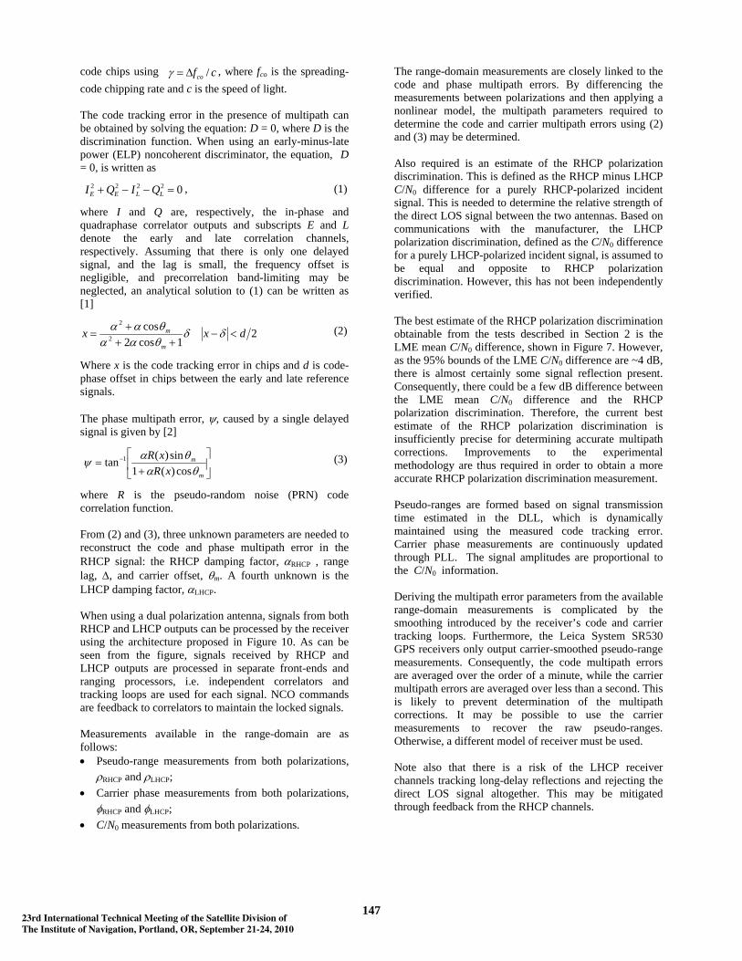
3.3 Tracking-domain multipath mitigation The final approach to mitigating multipath using a dual-polarization antenna is in the tracking domain. For each signal tracked, the RHCP and LHCP antenna outputs are separately correlated within the GNSS. However, both sets of correlator outputs, the Is and Qs, are output to a common set of acquisition and tracking algorithms. These algorithms generate the numerically-controlled oscillator (NCO) commands that control the reference code and carrier signals for both the RHCP and LHCP correlation channels. Figure 11 illustrates this. Tracking-domain multipath mitigation may be thought of as “deeply-coupled” and range-domain mitigation as “loosely-coupled”. Acquisition may use either the RHCP antenna signals alone or a summation of the signals from the RHCP and LHCP antennas. For tracking, the LHCP and RHCP Is and Qs are input separately to an algorithm that tracks both the direct LOS signal and the resultant reflected signal. Only the direct LOS signal tracking is used to generate the pseudo-range, pseudo-range rate and/or carrier phase measurements used by the positioning algorithm. Note that tracking-domain multipath mitigation also requires an accurate estimate of the RHCP polarization discrimination. Two approaches may be considered. The first is to use discriminator functions and separate tracking loops for the direct code, direct carrier, reflected code and reflected carrier, together with C/N0 measurement models for both polarizations. The second approach uses an extended Kalman filter (EKF) or nonlinear estimation algorithm to estimate the code phase, carrier phase, carrier frequency and signal amplitude or C/N0 for both the direct and resultant reflected signals. The Is and Qs from both sets of correlators are input directly as measurements. A similar multipath tracking filter for use with a single-polarization multiple-correlator receiver is described in [27].
5. HARDWARE DEVELOPMENT Using two separate receivers to process data from a dual-polarization antenna is cumbersome. Range-domain multipath mitigation must account for the timing difference between the two receiver clocks, while tracking-domain multipath mitigation can not be performed. Further limitations of the Leica receivers are that raw pseudo-range measurements are not available; only carrier-smoothed pseudo range, and that data can only be logged where sufficient signals are being received to generate a position solution. Therefore, a bespoke dual front-end GNSS receiver is being developed for use in further studies of dual-polarization multipath mitigation. In the current context of having the GNSS bandwidth occupied by several signals coming from the satellites in orbit, it is critical to produce a receiver that is capable of processing simultaneously a great number of these signals. The main difficulty resides in the fact that the satellites are able to broadcast signals with various frequencies and bandwidths. For example the GPS L1 is 1575.42 MHz with 2MHz of bandwidth while Galileo E6 is centred on 1278.75 MHz and occupies a bandwidth of 40 MHz. In this particular situation, the only way to take advantage of the GNSS satellites diversity is to design a receiver which can process all the frequencies at the same time. During several years, the GNSS front-end designers were using the superheterodyne architecture to build up GNSS receiver front-ends. Such solution has proved its efficiency, simplicity and cost effectiveness for single-frequency receivers. Today, as the GNSS receivers require multifrequency front-end solutions, it became challenging to produce a multifrequency receiver front-end that is based on the superheterodyne architecture. Previous work was conducted by several research teams, in which a bandpass sampling-based receiver was proposed as an alternative approach to building multifrequency receivers, replacing the usual superheterodyne architecture. For
Figure 11: Dual-polarization GNSS user equipment architecture with tracking-domain multipath mitigation
14823rd International Technical Meeting of the Satellite Division ofThe Institute of Navigation, Portland, OR, September 21-24, 2010
example, [29] has proposed an architecture of receiver prototype to be used for communication application. In the GNSS context, [30] was among of the firsts who devised a working receiver prototype based on bandpass sampling. On the other hand [31] and [32] work have pioneered the idea of using a reconfigurable software-defined radio (SDR) multifrequency receiver combined with a novel architecture of digital-to-analogue converters. In this paper, the ADVRG team at Westminster are proving a front-end that is capable of processing the maximum number of the channels with the minimum complexity and high level of flexibility. The front-end presented here, was achieved in context of the continuity of the [31] and [32] studies. It is also slightly inspired by the [33] work to provide a prototype of front-end ready for applications such as multipath mitigation, pecise point positioning (PPP) or integrity assessments.
FPGA Board
Virtex VI Xilinx FPGA
Low jitter Clock
OCXOCClk-
Clk+
PCIe Data Bus
ADC
DSP
GAIN Block
Filter/LNA BlockBPF BPF
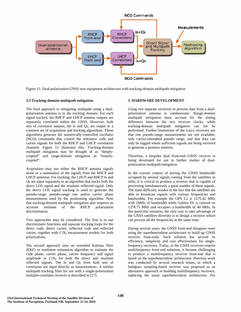
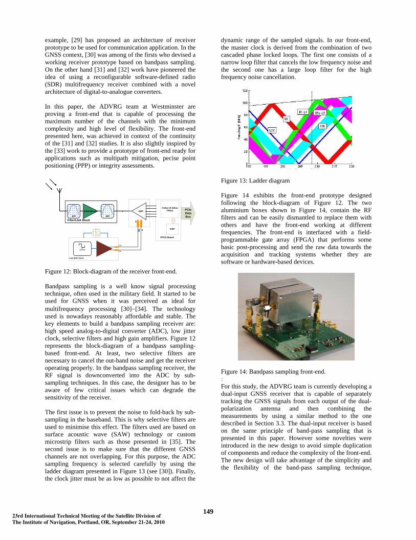
Figure 12: Block-diagram of the receiver front-end. Bandpass sampling is a well know signal processing technique, often used in the military field. It started to be used for GNSS when it was perceived as ideal for multifrequency processing [30]− [34]. The technology used is nowadays reasonably affordable and stable. The key elements to build a bandpass sampling receiver are: high speed analog-to-digital converter (ADC), low jitter clock, selective filters and high gain amplifiers. Figure 12 represents the block-diagram of a bandpass sampling-based front-end. At least, two selective filters are necessary to cancel the out-band noise and get the receiver operating properly. In the bandpass sampling receiver, the RF signal is downconverted into the ADC by sub-sampling techniques. In this case, the designer has to be aware of few critical issues which can degrade the sensitivity of the receiver. The first issue is to prevent the noise to fold-back by sub-sampling in the baseband. This is why selective filters are used to minimise this effect. The filters used are based on surface acoustic wave (SAW) technology or custom microstrip filters such as those presented in [35]. The second issue is to make sure that the different GNSS channels are not overlapping. For this purpose, the ADC sampling frequency is selected carefully by using the ladder diagram presented in Figure 13 (see [30]). Finally, the clock jitter must be as low as possible to not affect the
dynamic range of the sampled signals. In our front-end, the master clock is derived from the combination of two cascaded phase locked loops. The first one consists of a narrow loop filter that cancels the low frequency noise and the second one has a large loop filter for the high frequency noise cancellation.
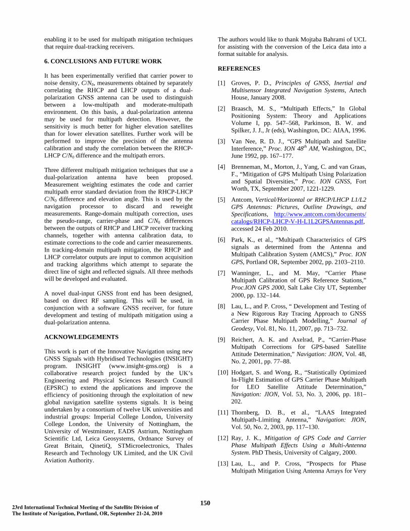
Figure 13: Ladder diagram Figure 14 exhibits the front-end prototype designed following the block-diagram of Figure 12. The two aluminium boxes shown in Figure 14, contain the RF filters and can be easily dismantled to replace them with others and have the front-end working at different frequencies. The front-end is interfaced with a field-programmable gate array (FPGA) that performs some basic post-processing and send the raw data towards the acquisition and tracking systems whether they are software or hardware-based devices.
Figure 14: Bandpass sampling front-end. : For this study, the ADVRG team is currently developing a dual-input GNSS receiver that is capable of separately tracking the GNSS signals from each output of the dual-polarization antenna and then combining the measurements by using a similar method to the one described in Section 3.3. The dual-input receiver is based on the same principle of band-pass sampling that is presented in this paper. However some novelties were introduced in the new design to avoid simple duplication of components and reduce the complexity of the front-end. The new design will take advantage of the simplicity and the flexibility of the band-pass sampling technique,
14923rd International Technical Meeting of the Satellite Division ofThe Institute of Navigation, Portland, OR, September 21-24, 2010
enabling it to be used for multipath mitigation techniques that require dual-tracking receivers. 6. CONCLUSIONS AND FUTURE WORK It has been experimentally verified that carrier power to noise density, C/N0, measurements obtained by separately correlating the RHCP and LHCP outputs of a dual-polarization GNSS antenna can be used to distinguish between a low-multipath and moderate-multipath environment. On this basis, a dual-polarization antenna may be used for multipath detection. However, the sensitivity is much better for higher elevation satellites than for lower elevation satellites. Further work will be performed to improve the precision of the antenna calibration and study the correlation between the RHCP-LHCP C/N0 difference and the multipath errors. Three different multipath mitigation techniques that use a dual-polarization antenna have been proposed. Measurement weighting estimates the code and carrier multipath error standard deviation from the RHCP-LHCP C/N0 difference and elevation angle. This is used by the navigation processor to discard and reweight measurements. Range-domain multipath correction, uses the pseudo-range, carrier-phase and C/N0 differences between the outputs of RHCP and LHCP receiver tracking channels, together with antenna calibration data, to estimate corrections to the code and carrier measurements. In tracking-domain multipath mitigation, the RHCP and LHCP correlator outputs are input to common acquisition and tracking algorithms which attempt to separate the direct line of sight and reflected signals. All three methods will be developed and evaluated. A novel dual-input GNSS front end has been designed, based on direct RF sampling. This will be used, in conjunction with a software GNSS receiver, for future development and testing of multipath mitigation using a dual-polarization antenna. ACKNOWLEDGEMENTS This work is part of the Innovative Navigation using new GNSS Signals with Hybridised Technologies (INSIGHT) program. INSIGHT (www.insight-gnss.org) is a collaborative research project funded by the UK’s Engineering and Physical Sciences Research Council (EPSRC) to extend the applications and improve the efficiency of positioning through the exploitation of new global navigation satellite systems signals. It is being undertaken by a consortium of twelve UK universities and industrial groups: Imperial College London, University College London, the University of Nottingham, the University of Westminster, EADS Astrium, Nottingham Scientific Ltd, Leica Geosystems, Ordnance Survey of Great Britain, QinetiQ, STMicroelectronics, Thales Research and Technology UK Limited, and the UK Civil Aviation Authority.
The authors would like to thank Mojtaba Bahrami of UCL for assisting with the conversion of the Leica data into a format suitable for analysis. REFERENCES [1] Groves, P. D., Principles of GNSS, Inertial and
Multisensor Integrated Navigation Systems, Artech House, January 2008.
[2] Braasch, M. S., “Multipath Effects,” In Global Positioning System: Theory and Applications Volume I, pp. 547–568, Parkinson, B. W. and Spilker, J. J., Jr (eds), Washington, DC: AIAA, 1996.
[3] Van Nee, R. D. J., “GPS Multipath and Satellite Interference,” Proc. ION 48th AM, Washington, DC, June 1992, pp. 167–177.
[4] Brenneman, M., Morton, J., Yang, C. and van Graas, F., “Mitigation of GPS Multipath Using Polarization and Spatial Diversities,” Proc. ION GNSS, Fort Worth, TX, September 2007, 1221-1229.
[5] Antcom, Vertical/Horizontal or RHCP/LHCP L1/L2 GPS Antennas: Pictures, Outline Drawings, and Specifications, http://www.antcom.com/documents/ catalogs/RHCP-LHCP-V-H-L1L2GPSAntennas.pdf, accessed 24 Feb 2010.
[6] Park, K., et al., “Multipath Characteristics of GPS signals as determined from the Antenna and Multipath Calibration System (AMCS),” Proc. ION GPS, Portland OR, September 2002, pp. 2103−2110.
[7] Wanninger, L., and M. May, “Carrier Phase Multipath Calibration of GPS Reference Stations,” Proc.ION GPS 2000, Salt Lake City UT, September 2000, pp. 132−144.
[8] Lau, L., and P. Cross, “ Development and Testing of a New Rigorous Ray Tracing Approach to GNSS Carrier Phase Multipath Modelling,” Journal of Geodesy, Vol. 81, No. 11, 2007, pp. 713−732.
[9] Reichert, A. K. and Axelrad, P., “Carrier-Phase Multipath Corrections for GPS-based Satellite Attitude Determination,” Navigation: JION, Vol. 48, No. 2, 2001, pp. 77–88.
[10] Hodgart, S. and Wong, R., “Statistically Optimized In-Flight Estimation of GPS Carrier Phase Multipath for LEO Satellite Attitude Determination,” Navigation: JION, Vol. 53, No. 3, 2006, pp. 181–202.
[11] Thornberg, D. B., et al., “LAAS Integrated Multipath-Limiting Antenna,” Navigation: JION, Vol. 50, No. 2, 2003, pp. 117–130.
[12] Ray, J. K., Mitigation of GPS Code and Carrier Phase Multipath Effects Using a Multi-Antenna System. PhD Thesis, University of Calgary, 2000.
[13] Lau, L., and P. Cross, “Prospects for Phase Multipath Mitigation Using Antenna Arrays for Very
15023rd International Technical Meeting of the Satellite Division ofThe Institute of Navigation, Portland, OR, September 21-24, 2010
High Precision Real-Time Kinematic Applications in the Presence of New GNSS Signals,” Proc. European Navigation Conference, Manchester, UK, May 2006.
[14] Van Dierendonck, A. J., P. Fenton, and T. Ford, “Theory and Performance of a Narrow Correlator Spacing in a GPS Receiver,” Navigation: Journal of the ION, Vol. 39, No. 3, 1992, pp. 265–283.
[15] Bétaille, D., P. A. Cross, and H.-J. Euler, “Assessment and improvement of the capabilities of a window correlator to model GPS multipath phase errors,” IEEE Transactions on Aerospace and Electronic Systems, Vol. 42, No. 2, 2006, pp. 707−718.
[16] Fenton, P. C., and J. Jones, “The Theory and Performance of NovAtel Inc.’s Vision Correlator,” Proc. ION GNSS 2005, .Long Beach, CA, September 2005, pp. 2178−2186.
[17] Pratt, A. R., “Performance of Multi-path Mitigation Techniques at Low Signal to Noise Ratios,” Proc. ION GNSS 2004. Long Beach, CA, September 2004, pp. 43–53.
[18] Hartinger, H., and F. K. Brunner, “Variances of GPS Phase Observations: The SIGMA-ε Model,” GPS Solutions, Vol. 2, No. 4, 1999, pp. 35−43.
[19] Wieser, A., and F. K. Brunner, “An extended weight model for GPS phase observations,” Earth Planets Space, Vol. 52, 2000, pp. 777−782.
[20] Wieser, A., and F. K. Brunner, “SIGMA-F: Variances of GPS Observations Determined by a Fuzzy System,” Proc. International Association of Geodesy Symposia 125: Vistas for Geodesy in the New Millennium, Springer Verlag, 2002, pp. 365−370.
[21] Lau, L., and E. Mok, “Improvement of GPS Relative Positioning Accuracy By Using SNR,” Journal of Surveying Engineering, Vol. 125, No. 4, 1999, pp. 185−202.
[22] Lau, L., and P. Cross, “A New Signal-to-Noise-Ratio Based Stochastic Model for GNSS High-Precision Carrier Phase Data Processing Algorithms in the Presence of Multipath Errors,” Proc. ION GNSS 2006, Fort Worth, Texas, September 2006, pp. 26−29.
[23] Comp, C. J., and P. Axelrad, “An Adaptive SNR-based Carrier Phase Multipath Mitigation Technique,” Proc. ION GPS-96, Kansas City, MO, September 1996, pp. 683−697.
[24] Lau, L., and P. Cross, “Use of Signal-To-Noise Ratio for Real-Time GNSS Phase Multipath Mitigation,” Proc. NAV05, London, UK, November 2005.
[25] Manandhar, D., Shibasaki, R. and Normark P., 2004. GPS Signal Analysis using LHCP/RHCP Antenna
and Software GPS Receiver, Proc. ION GNSS, Long Beach, CA, September 2004, pp. 2480−2498.
[26] Yang, C., and A. Porter, “GPS Multipath Estimation and Mitigation Via Polarization Sensing Diversity: Parallel Iterative Cross Cancellation,” Proc. ION GNSS, Long Beach, CA, September 2005, pp.2707-2719.
[27] A Izadpanah, Parameterization of GPS L1 Multipath Using a Dual Polarized RHCP/LHCP Antenna, MSc Thesis and UCGE Report no. 20280, University of Calgary, 2009.
[28] Groves, P. D., “GPS signal to noise measurement in weak signal and high interference envrironments,” Navigation: JION, Vol. 52, No. 2, 2005, pp. 83–92.
[29] H. Kim, J. Kim, JH. Kim, H. Wang, and I. Lee, “RF Band-Pass Sampling Frontend for Multiband Access CR/SDR Receiver”, ETRI Journal, vol.32, no.2, Apr. 2010, pp.214-221.
[30] Akos, D.M.; Stockmaster, M.; Tsui, J.B.Y.; Caschera, J., “Direct bandpass sampling of multiple distinct RF signals”, IEEE Trans. on Communication, Vol. 47, No. 7, 1999.
[31] A. Ucar, E. Cetin and I. Kale, “Reconfigurable SDR Receiver for Multi-Mode GNSS Applications”, Proceedings of the SDR ’08 Technical Conference and product Exposition, 2008.
[32] Ucar, A.; Cetin, E.; Kale, “On the implications of Analog-to-Digital Conversion on variable-rate BandPass Sampling GNSS receivers”, Signals, Systems and Computers, 2008 42nd Asilomar Conference, Oct. 2008.
[33] Lamontagne, G. « Conception électrique d'un échantillonneur direct en bande L des signaux des GNSS ». Rapport technique de projet sythèse en génie électrique, École de technologie supérieure, 2007.
[34] Adane, Yacine and Kale, Izzet, “RF front-end design for full constellation SDR based GNSS receivers,” IGNSS 2009, Book of abstracts p. 38.
[35] Y. Adane, A. Constantinescu, J. Belzile, A. Kouki, "Design of Miniature RF Band-pass Filters for a Hybrid GPS/Galileo Receiver Front-End Insert", ION NTM 2007, 22-24 January, San Diego, CA, p350-356.
15123rd International Technical Meeting of the Satellite Division ofThe Institute of Navigation, Portland, OR, September 21-24, 2010