Embed Size (px)
Citation preview
1
Novel hybrid WDM/TDM PON architectures to
manage flexibility in optical access networks
Bart Lannoo, Goutam Das, Abhishek Dixit, Didier Colle, Mario Pickavet, Piet
Demeester
Ghent University - iMinds, Gaston Crommenlaan 8, box 201, B-9050 Gent,
Belgium
Phone: +32 9 3314998
Fax: +32 9 3314899
Email: [email protected]
Website: http://www.ibcn.intec.ugent.be
Abstract: Different hybrid WDM/TDM PON architectures are compared in terms of flexibility,
simplicity (affecting the cost), insertion loss (affecting the reach) and security. Special attention is
given to the flexibility aspect in next generation optical access networks by designing different
architectures with a different degree of flexibility, which are able to cope with different ranges of
dynamic bandwidth allocation (DBA) possibilities. This paper assesses the degree of architectural
flexibility needed to deal with some important flexibility advantages. It is shown that mostly a
partially flexible architecture fulfils the needs. The architectures are then further evaluated from a
cost and reach perspective. In this way, we provide a complete comparison considering all the key
aspects of access network design. It is shown that a hybrid WDM/TDM PON with a partially
flexible architecture in the first remote node can be an interesting candidate for next-generation
optical access networks.
Keywords: optical access, PON architectures, hybrid WDM/TDM, flexibility,
dynamic bandwidth allocation
1. Introduction
Currently, telecom operators are adapting their broadband access networks for
offering highly demanding services such as high-definition TV, interactive
gaming, video-conferencing, etc. Optical fiber networks are considered the most
future-proof next generation access (NGA) technologies. Nowadays, the most
used optical fiber access network configuration is a (power splitting) time division
multiplexing (TDM) passive optical network (PON), with Ethernet PON (EPON)
and gigabit-capable PON (GPON) as the two most important standards [1]-[3].
The currently deployed EPON or GPON systems, however, are unable to provide
the expected residential data rates by the year 2020, being a sustainable data rate
2
of 500 Mbps per user (or subscriber) and a peak data rate of 1 Gbps per user [4].
Typically these PON systems are using a separate wavelength (of 1 or 2.5 Gbps)
for down- and upstream, and both wavelengths are then shared between multiple
users (e.g., 16, 32, 64). As the users share the same pool of capacity, competition
may arise and traffic requests may not be honored due to congestion.
The mentioned capacity bottleneck for TDM PONs is currently tackled by the
standardization activities for the 10G xPON systems (10G EPON and 10G GPON,
respectively). The physical access bit rate is pushed to 10 Gbps per wavelength,
firstly for the downlink part and secondly in a symmetric offer for the uplink part.
Another attractive PON solution is the wavelength division multiplexing (WDM)
PON, offering two separate wavelength channels per subscriber. A pure WDM
PON provides an individual down- and upstream wavelength channel to each
user, and thus there is no competition among them and no congestion will occur in
the network. However, there is also no opportunity to share capacity among the
subscribers, and to use the available network resources in a flexible way.
Introducing a WDM dimension on top of a TDM PON system combines the
increased capacity delivered by WDM and the inherent capacity sharing of a
TDM PON, and it is an important candidate for next-generation optical access
(NGOA) networks. Different hybrid WDM/TDM PON flavors, with a varying
remote node architecture, are presented in this paper and compared to each other
from several perspectives. Special attention is given to the flexibility aspect by
designing an architecture that is able to cope with dynamic bandwidth allocation
(DBA) in the time and wavelength domain. Additionally, the considered hybrid
WDM/TDM PON architectures are also evaluated from a cost and reach
perspective. For the cost evaluation, a 10G technology is considered, taking into
account reasonable target costs for the optical components. This evaluation leads
to a better understanding of the additional cost for introducing flexibility. The
reach calculation is based on the insertion loss of the different hybrid WDM/TDM
PON architectures. With the growing interest for long-reach PON, the passive
reach of a PON is becoming an important parameter for an architecture selection.
Note that a long-reach PON is in favor of several operators that want to reduce the
number of central offices in their network, referred to as node consolidation.
The remainder of this paper is organized as follows. In Section 2, different
WDM/TDM PON architectures are described, accompanied with a high-level
3
evaluation in terms of flexibility, simplicity, insertion loss and security. The
motivation for introducing flexibility in NGOA networks is highlighted in Section
3. Further, the needed degree of flexibility in hybrid WDM/TDM PONs is
evaluated in Section 4. Finally, Section 5 evaluates the main constraints raised by
an increased flexibility, i.e. an increased cost and insertion loss.
2. Hybrid WDM/TDM PON architectures
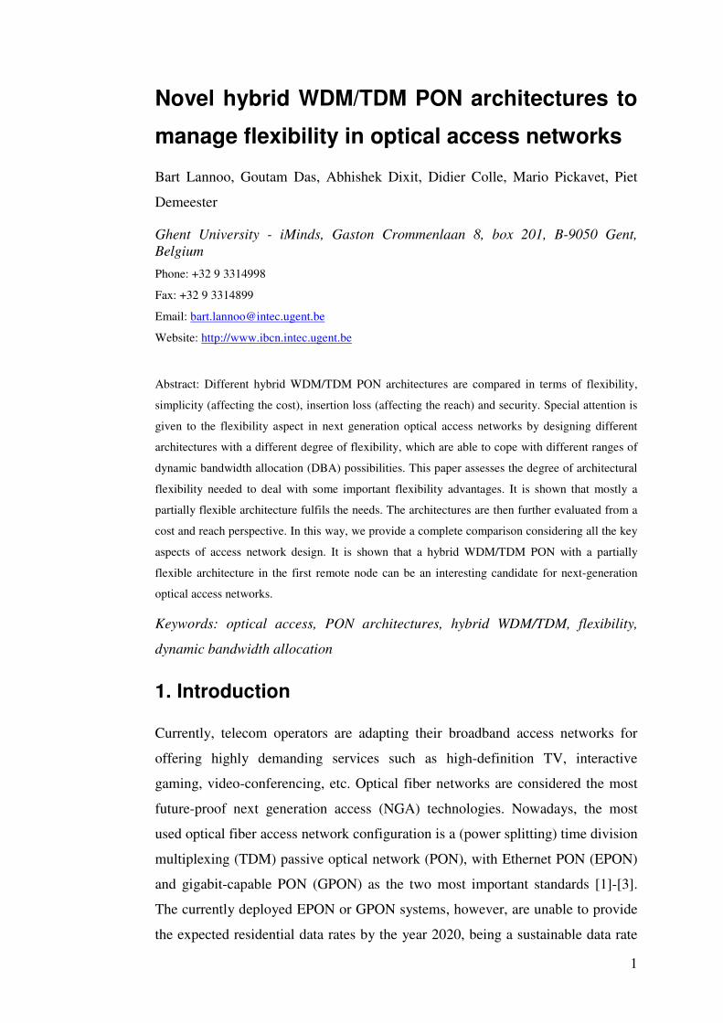
A general architecture of a (flexible) hybrid WDM/TDM PON is shown in Figure
1. Three network parts are indicated between the optical line terminal (OLT) in
the central office (CO) and the optical network unit (ONU) at the user side: feeder
between OLT and remote node 1 (RN1), distribution between RN1 and RN2, and
last mile between RN2 and ONU. In RN2, a passive power splitter (1:N) is
installed, which means that RN1 is connected to M TDM PON architectures.
Central office /
Local exchange
Remote node 1 Remote node 2 User
Feeder Distribution Last mile
N
RN 1M
ONU
OLT
Figure 1: General hybrid WDM/TDM PON architecture
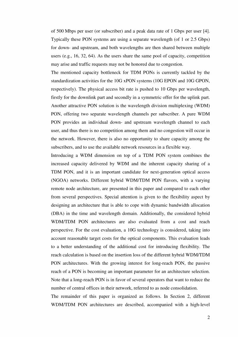
Figure 2 shows the architectures of the considered OLT and ONU. The OLT
consists of Wu uplink line cards and photo detectors (PD) and Wd downlink line
cards and distributed-feedback (DFB) lasers. All upstream/downstream
wavelengths are (de)multiplexed by using e.g., two arrayed waveguide gratings
(AWGs) as wavelength splitter/combiner, and both wavelength bands are put on
the same fiber by using a three-port circulator. The ONU contains a three-port
circulator to separate upstream and downstream wavelengths. Further, the
upstream part of the ONU has an uplink line card and a tunable burst mode
transmitter (Tx) for tuning to any desired wavelength. The downstream part has a
downlink line card, a classical PD and a tunable optical filter for selecting the
desired wavelength. Note that with the current technologies, the realization of
4
tunable optical filters with sharp notches, required for hybrid WDM/TDM PONs,
can be very expensive, but our believe is that these devices will be available in the
future for reasonable cost to be used for access technologies.
Do
wn
link c
on
trol
Downlink
line card
Uplink
line cardUp
link c
on
trol
Wd
Wu
DFB
DFB
DFB
PD
PD
PD
OLT
Tunable
optical filter
ON
U c
on
trol
PD
Uplink
line card
Downlink
line card
Tunable
Burst Mode
Transmitter
ONU
Figure 2: Architecture of OLT (left) and ONU (right)
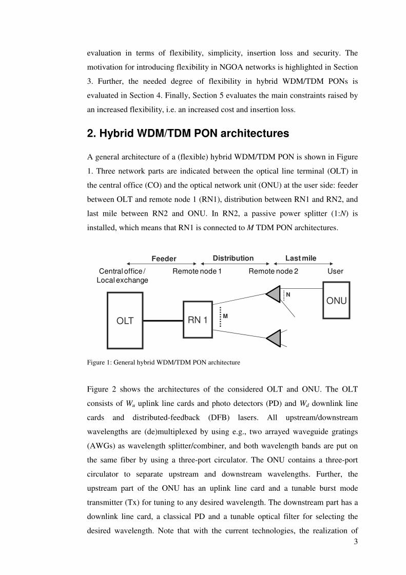
By varying RN1, three main categories of hybrid WDM/TDM PONs are
presented in this section, each with a different degree of flexibility: (1) fully
flexible, (2) fully static and (3) partially flexible. Strictly speaking some of the
presented hybrid WDM/TDM PON flavors are no longer passive because they
may need some (simple) active elements in RN1. However, in these architectures,
the data transfer remains optically transparent, and only the control needs optical-
electrical-optical (OEO) conversion. We can also refer to these systems as semi-
passive, but in general the term PON is still used.
Choosing the best architecture is typically a trade-off between flexibility on one
hand, and cost, reach and security constraints on the other hand. In this section, a
basic assessment for the different architectures is presented, based on the
following criteria: flexibility, simplicity (related to cost), insertion loss (related to
reach) and security.
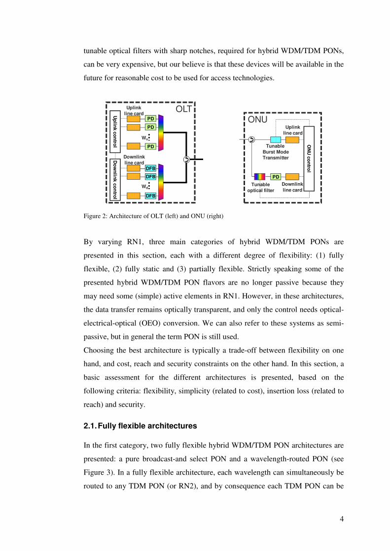
2.1. Fully flexible architectures
In the first category, two fully flexible hybrid WDM/TDM PON architectures are
presented: a pure broadcast-and select PON and a wavelength-routed PON (see
Figure 3). In a fully flexible architecture, each wavelength can simultaneously be
routed to any TDM PON (or RN2), and by consequence each TDM PON can be
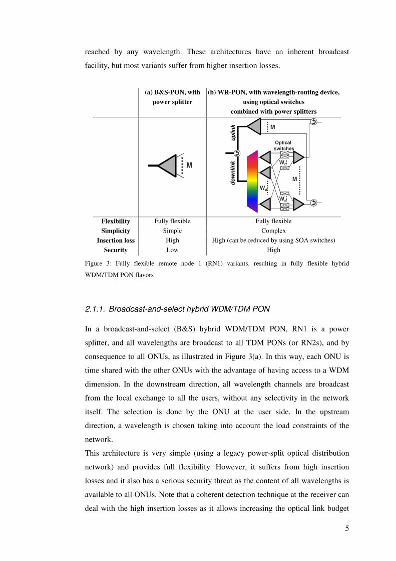
5
reached by any wavelength. These architectures have an inherent broadcast
facility, but most variants suffer from higher insertion losses.
(a) B&S-PON, with
power splitter
(b) WR-PON, with wavelength-routing device,
using optical switches
combined with power splitters
M
M
M
up
lin
kd
ow
nlin
k
Wd
Wd
Wd
Optical
switches
Flexibility Fully flexible Fully flexible
Simplicity Simple Complex
Insertion loss High High (can be reduced by using SOA switches)
Security Low High
Figure 3: Fully flexible remote node 1 (RN1) variants, resulting in fully flexible hybrid
WDM/TDM PON flavors
2.1.1. Broadcast-and-select hybrid WDM/TDM PON
In a broadcast-and-select (B&S) hybrid WDM/TDM PON, RN1 is a power
splitter, and all wavelengths are broadcast to all TDM PONs (or RN2s), and by
consequence to all ONUs, as illustrated in Figure 3(a). In this way, each ONU is
time shared with the other ONUs with the advantage of having access to a WDM
dimension. In the downstream direction, all wavelength channels are broadcast
from the local exchange to all the users, without any selectivity in the network
itself. The selection is done by the ONU at the user side. In the upstream
direction, a wavelength is chosen taking into account the load constraints of the
network.
This architecture is very simple (using a legacy power-split optical distribution
network) and provides full flexibility. However, it suffers from high insertion
losses and it also has a serious security threat as the content of all wavelengths is
available to all ONUs. Note that a coherent detection technique at the receiver can
deal with the high insertion losses as it allows increasing the optical link budget
6
up to 50 dB (compared to ca. 30 dB for direct detection techniques in current PON
architectures). For an access network, however, coherent detection is still a very
complicated and expensive technique, and as such we do not consider it in the
remainder of this paper. Currently, coherent detection is investigated for the so-
called Ultra Dense WDM PON presented in [5]. This is a pure WDM PON
architecture with a 1:1000 split ratio using a fully passive architecture (only using
power splitters).
2.1.2. Wavelength-routed hybrid WDM/TDM PON
In a wavelength-routed (WR) hybrid WDM/TDM PON, RN1 allows a flexible
wavelength routing by adding an active wavelength-routing device (or
configurable optical switch) in RN1. An example of a fully flexible wavelength-
routing device is shown in Figure 3 (b), consisting of a WDM splitter, a passive
splitter stage, optical switches and a passive combiner stage in the downlink
direction. Each TDM PON (or RN2) can get data from all downstream
wavelengths, and this is controlled by the optical switches. Each wavelength, on
its turn, can be routed to one or more TDM PONs, providing a selected and
dynamic multicast environment. In the uplink direction, the data streams from the
different TDM PONs (or RN2) are combined through an M×1 combiner. The
uplink and downlink data streams are combined by a three-port circulator. This
architectural solution is also referred to as active routing optical access network
(ARON) architecture, and is studied in more detail in [6]-[8].
This implementation improves the broadcast nature and security concerns of the
B&S-PON. In general, this architecture also suffers from high insertion losses, but
by using fast-switching SOA switches, the high losses due to the couplers and
splitters can be partially compensated, but at the cost of a more expensive solution
than when e.g. micro-electro-mechanical systems (MEMS) switches are used. In
the insertion loss and reach calculations of Section 5, however, we will prove that
for a high fan-out case (with e.g. 1000 subscribers per OLT), this architecture,
even with SOA switches, is not able to provide a minimum reach of some
kilometers.
7
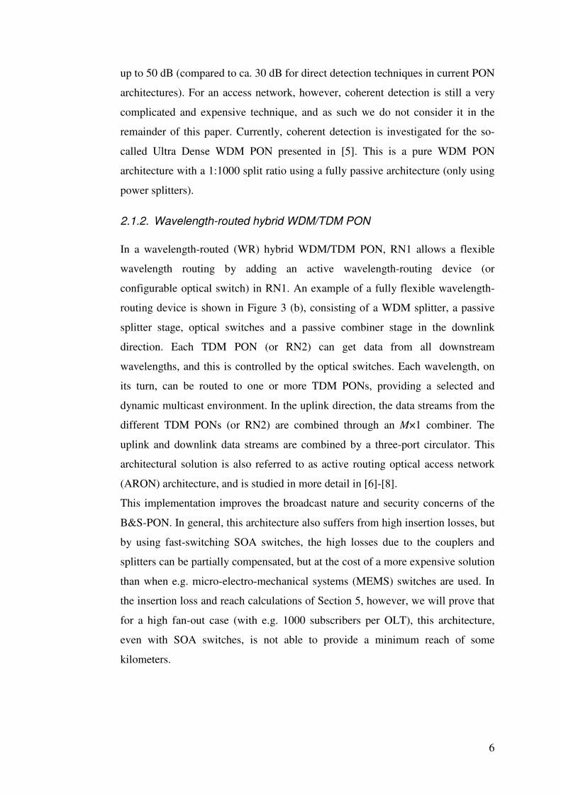
2.2. Fully static architectures
In the second category, a fully static hybrid WDM/TDM PON architecture with
only one variant is presented: a wavelength-split PON (see Figure 4). In a fully
static architecture, each wavelength is routed to only one fixed TDM PON (or
RN2), and each TDM PON can be reached by only one fixed wavelength. Such an
architecture has a low insertion loss and high security.
(a) WS-PON, with AWG
M
up
lin
kd
ow
nlin
k
M
Flexibility Fully static
Simplicity Simple
Insertion loss Low
Security High
Figure 4: Fully static remote node 1 (RN1), resulting in a fully static hybrid WDM/TDM PON
2.2.1. Wavelength-split hybrid WDM/TDM PON
In a wavelength-split (WS) hybrid WDM/TDM PON, a passive wavelength
splitter or filter (e.g., AWG) is put in RN1 to distribute different wavelengths to
different TDM PONs, as shown in Figure 4, with Wu = Wd = M. This architecture
is also extensively discussed in literature, e.g. [9]-[10]. Note that a separate AWG
is depicted for the up- and downlink direction, as typically different wavelength
bands are used for upstream (e.g. C-band, 1530 - 1565 nm) and for downstream
(e.g. L-band, 1565 - 1625 nm). If the same wavelength band is used, a single
AWG can be used for both the up- and downlink part.
As a wavelength splitter has a much lower insertion loss compared to a passive
power splitter, this architecture has a longer reach and can support more users.
However, the flexibility is very restricted as each wavelength is connected to a
fixed TDM PON, this cannot be rearranged with e.g. a changing traffic demand.
8
2.3. Partially flexible architectures
In the third category, different partially flexible hybrid WDM/TDM PON
architectures are presented. These architectures are typically more costly than the
fully flexible or fully static counterparts, but they have a higher security and lower
insertion loss than the fully flexible architectures, and are, of course, more flexible
than a fully static architecture. Often, a trade-off between these different
parameters will decide about the best architecture in a specific situation.
In all partially flexible architectures, each TDM PON can be reached by multiple
wavelengths. However, each wavelength can reach either multiple or only one
TDM PON, and for that reason, we divide these architectures in two main
categories: architectures with and without multicasting, respectively.
2.3.1. Partially flexible architectures, with multicasting
Three variants of a partially flexible hybrid WDM/TDM PON architecture with
multicasting, are discussed in this section (see Figure 5). In a partially flexible
architecture with multicasting, each wavelength can be routed to multiple TDM
PONs (but not all TDM PONs can be reached by one wavelength at a time). As
for all partially flexible architectures, each TDM PON can be reached by multiple
wavelengths. The most straightforward way to implement such a partially flexible
architecture is attained by combining the B&S-PON and the WS-PON, i.e. a
combination of power splitters and AWGs. However, more complex alternatives
can be designed to enhance the flexibility, and two examples using a wavelength
selective switch (WSS) instead of an AWG are discussed in this section. Note that
all variants are making use of power splitters to offer multicasting.
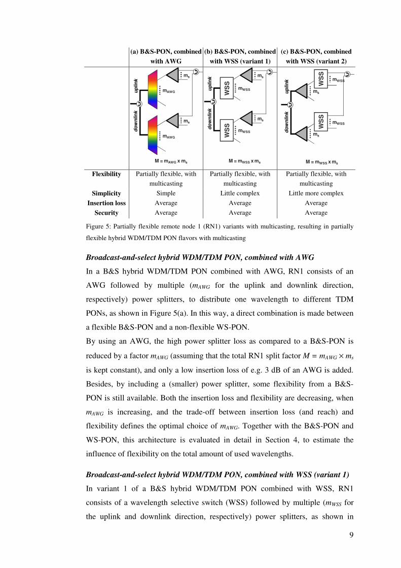
9
(a) B&S-PON, combined
with AWG
(b) B&S-PON, combined
with WSS (variant 1)
(c) B&S-PON, combined
with WSS (variant 2)
up
lin
kd
ow
nlin
k
mAWG
ms
mAWG
ms
M = mAWG x ms
up
lin
kd
ow
nlin
k
mWSS
ms
ms
WS
SW
SS
mWSS
M = mWSS x ms
up
lin
kd
ow
nlin
k
ms
mWSS
WS
S
ms
mWSS
WS
S
M = mWSS x ms
Flexibility Partially flexible, with
multicasting
Partially flexible, with
multicasting
Partially flexible, with
multicasting
Simplicity Simple Little complex Little more complex
Insertion loss Average Average Average
Security Average Average Average
Figure 5: Partially flexible remote node 1 (RN1) variants with multicasting, resulting in partially
flexible hybrid WDM/TDM PON flavors with multicasting
Broadcast-and-select hybrid WDM/TDM PON, combined with AWG
In a B&S hybrid WDM/TDM PON combined with AWG, RN1 consists of an
AWG followed by multiple (mAWG for the uplink and downlink direction,
respectively) power splitters, to distribute one wavelength to different TDM
PONs, as shown in Figure 5(a). In this way, a direct combination is made between
a flexible B&S-PON and a non-flexible WS-PON.
By using an AWG, the high power splitter loss as compared to a B&S-PON is
reduced by a factor mAWG (assuming that the total RN1 split factor M = mAWG × ms
is kept constant), and only a low insertion loss of e.g. 3 dB of an AWG is added.
Besides, by including a (smaller) power splitter, some flexibility from a B&S-
PON is still available. Both the insertion loss and flexibility are decreasing, when
mAWG is increasing, and the trade-off between insertion loss (and reach) and
flexibility defines the optimal choice of mAWG. Together with the B&S-PON and
WS-PON, this architecture is evaluated in detail in Section 4, to estimate the
influence of flexibility on the total amount of used wavelengths.
Broadcast-and-select hybrid WDM/TDM PON, combined with WSS (variant 1)
In variant 1 of a B&S hybrid WDM/TDM PON combined with WSS, RN1
consists of a wavelength selective switch (WSS) followed by multiple (mWSS for
the uplink and downlink direction, respectively) power splitters, as shown in
10
Figure 5(b). In this architecture, the (static) AWG from the previous architecture
is replaced by a (reconfigurable) WSS [11].
WSSs are generally implemented in MEMS that provide low insertion loss
wavelength switching capabilities. A WSS can steer each wavelength channel
present on its common input port towards one of its output ports. In contrast to an
AWG, this output port is no longer static, but can be selected by the WSS,
enhancing the flexibility of RN1. Off-the-shelf WSS can have the functionality of
1×2, 1×4 or 1×8 switching. A WSS has the capability of steering one wavelength
from an output port to another one if the users attached to the concerned output
port do not require the service of that wavelength anymore. From a reach and
security perspective, there is no much difference between using an AWG and
WSS (e.g., we can assume that the insertion loss of a WSS is in the same order of
magnitude as the loss of an AWG). The main disadvantage of using a WSS,
however, is its comparatively high cost, as discussed in Section 5.
Broadcast-and-select hybrid WDM/TDM PON, combined with WSS (variant 2)
In variant 2 of a B&S hybrid WDM/TDM PON, combined with WSS, RN1
consists of a power splitter followed by multiple (ms for the uplink and downlink
direction, respectively) WSSs, as shown in Figure 5(c). In this architecture, the
power splitter and WSS are changed from order compared to the previous
architecture. This hybrid WDM/TDM PON flavor is discussed in detail in [12].
As the power splitter is put in front of the WSS, the flexibility is further enhanced,
as RN1 can now do a limited (flexible) multicasting. The same wavelength can be
multicast to ms different output ports of RN1, provided they are attached to
different WSS modules. The reach and security aspects are comparable to the
previous partially flexible architectures. The main disadvantage of this second
variant of a WSS-based B&S-PON architecture, compared to the first variant, is
its higher cost due to the use of a higher amount of WSSs (ms instead of 1 for the
uplink and downlink direction, respectively).
2.3.2. Partially flexible architectures, without multicasting
Two variants of a partially flexible hybrid WDM/TDM PON architecture without
multicasting, are discussed in this section (see Figure 6). In a partially flexible
architecture without multicasting, each wavelength can be routed to one TDM
PON only at a time (i.e., no multicasting of a wavelength among multiple TDM
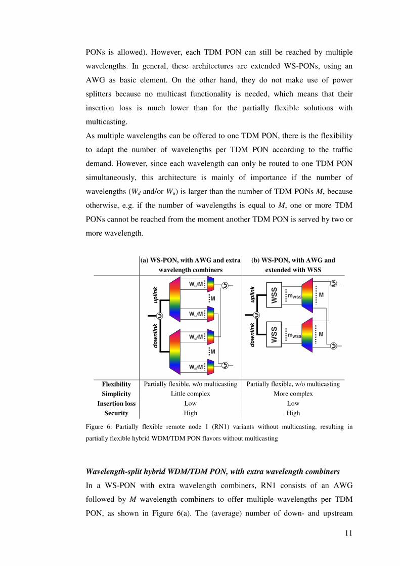
11
PONs is allowed). However, each TDM PON can still be reached by multiple
wavelengths. In general, these architectures are extended WS-PONs, using an
AWG as basic element. On the other hand, they do not make use of power
splitters because no multicast functionality is needed, which means that their
insertion loss is much lower than for the partially flexible solutions with
multicasting.
As multiple wavelengths can be offered to one TDM PON, there is the flexibility
to adapt the number of wavelengths per TDM PON according to the traffic
demand. However, since each wavelength can only be routed to one TDM PON
simultaneously, this architecture is mainly of importance if the number of
wavelengths (Wd and/or Wu) is larger than the number of TDM PONs M, because
otherwise, e.g. if the number of wavelengths is equal to M, one or more TDM
PONs cannot be reached from the moment another TDM PON is served by two or
more wavelength.
(a) WS-PON, with AWG and extra
wavelength combiners
(b) WS-PON, with AWG and
extended with WSS
M
up
lin
kd
ow
nlin
k
Wu/M
Wu/M
Wd/M
Wd/M
M
M
WS
S
mWSS
M
WS
S
mWSS
up
lin
kd
ow
nlin
k
Flexibility Partially flexible, w/o multicasting Partially flexible, w/o multicasting
Simplicity Little complex More complex
Insertion loss Low Low
Security High High
Figure 6: Partially flexible remote node 1 (RN1) variants without multicasting, resulting in
partially flexible hybrid WDM/TDM PON flavors without multicasting
Wavelength-split hybrid WDM/TDM PON, with extra wavelength combiners
In a WS-PON with extra wavelength combiners, RN1 consists of an AWG
followed by M wavelength combiners to offer multiple wavelengths per TDM
PON, as shown in Figure 6(a). The (average) number of down- and upstream
12
wavelengths provided to each TDM PON is equal to Wd/M and Wu/M,
respectively. From these formulas, it is also clear that this architecture only makes
sense if Wd (or Wu) > M. If Wd (or Wu) = M, this architecture is reduced to the WS-
PON from Figure 4.
Wavelength-split hybrid WDM/TDM PON, extended with WSS
In a WS-PON extended with WSS, RN1 consist of a WSS followed by an AWG,
as shown in Figure 6(b). Compared to a WS-PON, a WSS enhances the
wavelength reconfigurability among the subscribers according to their traffic
demand. In particular, the WSS can select which wavelength to be routed to
which input port of the AWG. Combing a WSS with an AWG provides partial
flexibility of choosing multiple (with a maximum equal to the number of WSS
output ports, i.e. mWSS) wavelengths to be routed to a particular output port of the
AWG. This architecture is also presented in [12].
As only a maximum of mWSS wavelengths can reach a particular TDM PON (or
RN2), we can increase the flexibility of the proposed architecture by increasing
the number of output ports per WSS. This brings a cost versus flexibility tradeoff
issue in the architecture design. As for all WSS-based PONs, there is a costly
WSS required, but just as in variant 1 of the B&S hybrid WDM/TDM PON
architecture combined with WSS, this solution only requires one WSS for
upstream and downstream, respectively.
3. Motivation to add flexibility in access networks
The flexibility to offer any bandwidth (in the limit of the physical bit rate) to
anybody could be a major advantage for NGOA networks. A hybrid WDM/TDM
PON with DBA in the time and wavelength domain can combine the virtues of
both the TDM and WDM solutions. The introduction of a WDM layer allows for
an increase of both the number of users and total data rates, while the granularity
of the TDM layer on top of the WDM layer offers a better bandwidth usage,
scalability and upgradeability than a pure WDM PON. By combining WDM and
TDM, a lot of demands can coexist on the same network infrastructure in a very
efficient manner. This is a strong advantage when compared to other systems.
From the OLT, multiple TDM PONs can be set up, each at a specific wavelength.
Each TDM PON serves a set of users, and within this set, the capacity is shared.
By means of wavelength selection or routing, the number of users within the set
13
can be varied, and thus the capacity offered per user can be varied. Hence a
flexible hybrid WDM/TDM PON can offer capacity-on-demand, and the
congestion probability can be significantly reduced compared to a static
wavelength configuration. The main advantages of a flexible hybrid WDM/TDM
PON are highlighted in the next subsection. Then, the most important options for
implementing this flexibility are described, and finally the constraints that come
into the picture are treated.
3.1. Advantages offered by flexibility
If flexibility can be added at RN1, so that any wavelength can be steered to any or
a part of the passive power splitters in RN2, it is possible to improve the network
performance like bandwidth utilization and delay, the energy efficiency of the
overall network operation, the extensibility of the network, as well as the smooth
migration to next-generation network technologies. In the next subsections, we
give a brief account of the four most striking features of this architecture that
separate it from most of the other PON architectures, i.e., network performance,
energy efficiency, network extensibility and the network migration.
3.1.1. Network performance
A (partially) flexible network architecture naturally provides the means to have an
improved network performance (like bandwidth utilization and delay) by applying
advanced resource allocation techniques. Combing the WDM and TDM layer
allows a better installation of a DBA scheme due to the wavelength allocation
flexibility, and it enjoys a better statistical-multiplexing gain and bandwidth-usage
efficiency. The use of power splitters in the proposed hybrid WDM/TDM PONs
allows us to broadcast wavelengths to multiple user groups, and by using DBA
protocols, we can select users per wavelength on the basis of their network load.
As we use a passive power splitter, a wavelength splitter (or filter), or an active
optical switch (e.g., SOA, MEMS, WSS), it keeps the data layer transparent in all
the remote nodes, and hence reduces the overall network processing time and data
transfer delays, and eventually supports maintaining more stringent quality of
service requirements. Efficient bandwidth utilization also leads to energy
efficiency as we have to use a smaller number of wavelengths, and by
consequence less line cards, for attaining the same network performance.
14
3.1.2. Network extensibility
The network extensibility means the efficient deployment strategies that the
hybrid WDM/TDM PON architecture can promote while constantly expanding
the network by the incremental installation of network equipment according to the
connectivity demand of the end users. Due to the inherent flexibility, the proposed
architecture can be used for green- or brown-field installation where the network
connectivity demand can change and evolve over time. The example provided in
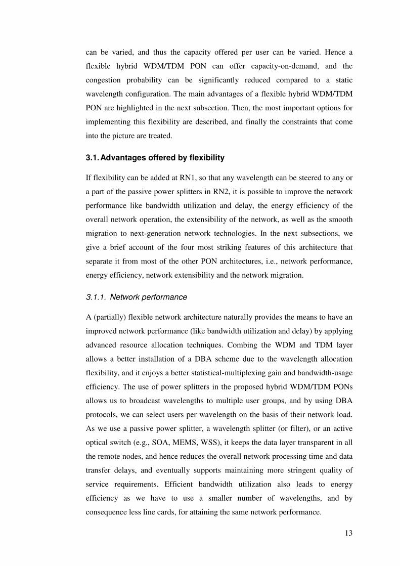
Figure 7 explains the concept in a more illustrative way.
OLT OLT
Figure 7: Illustration of a network extensibility scenario for flexible hybrid WDM/TDM PONs
Figure 7 provides an example where the first remote node has physically three
possible splitting stages. Now, initially as shown in the left part of Figure 7, the
number of users connected to the second and third splitting-point is less than
optimal. Therefore due to the wavelength flexibility of our architecture, we can
allocate a single wavelength (green for example) to all the users attached to the
second and third splitting-point as depicted in Figure 7 and therefore use just two
transceivers and line cards at the OLT. As the demand increases, and more
subscribers are added to the relevant splitting-points, the OLT can have added line
cards to fulfill the demands of the expanded network, and the wavelengths at the
user premises can be reallocated to cope with the individual traffic needs as
shown in the right-hand part of the Figure 7. This provides a means for the
operator for a smooth and incremental expansion of the network according to the
demand, while keeping the basic network infrastructure deployed in the field
undisturbed.
15
3.1.3. Energy efficiency
Our proposal for energy efficiency has a similar argument as provided for the
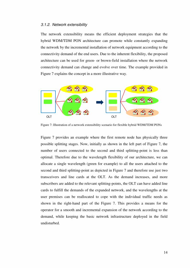
network extensibility. An illustrative example is provided in Figure 8 to
demonstrate this. The left part of Figure 8 shows that over time, users who require
almost no services (e.g., business users during the night time hours) can be
reconnected to a particular wavelength. In this scenario, the wavelength can be
reallocated as shown in the right-hand part of Figure 8 and this provides a mean to
turn off some of the OLT transceivers as well as line cards, to enhance energy
savings at the OLT over time. This might help the operator to build its network
greener. The same scheme also depicts the possibility of dynamic allocation of
wavelengths amongst users according to their traffic needs.
OLT OLT
Turn off
Figure 8: Illustration of an energy efficiency scenario for flexible hybrid WDM/TDM PONs
3.1.4. Network migration
Our proposal for network migration corresponds to an efficient migration strategy
that the proposed architecture can support during e.g. a technology upgrade. In
this way, co-existence of a new technology with the legacy system is made
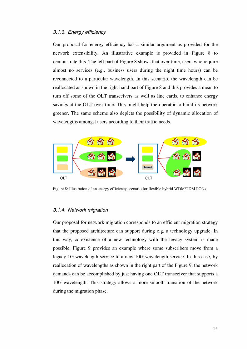
possible. Figure 9 provides an example where some subscribers move from a
legacy 1G wavelength service to a new 10G wavelength service. In this case, by
reallocation of wavelengths as shown in the right part of the Figure 9, the network
demands can be accomplished by just having one OLT transceiver that supports a
10G wavelength. This strategy allows a more smooth transition of the network
during the migration phase.
16
1G
1G
1G
10G1G →→→→ 10G
OLT
1G
1G
1G
10G1G →→→→ 10G
OLT
Figure 9: Illustration of a network migration scenario for flexible hybrid WDM/TDM PONs
3.2. Options to implement flexibility
To capture the above advantages, one needs to carefully assess the flexibility
options. In general, there exist two different kinds of flexibility depending on the
architecture choice.
3.2.1. Short-term flexibility
Short-term flexibility means in the limit that every medium access control (MAC)
frame can individually be allocated to a certain ONU. However, typically a group
of frames are allocated per ONU as otherwise the DBA scheme will be very
inefficient due to the huge overhead for accessing each frame individually. Such a
group of frames is called a burst, and in this way we can also refer to short-term
flexibility as burst-by-burst flexibility. Such a burst-by-burst flexibility is possible
with a fully-passive, B&S-PON-based architecture, where every wavelength is
multicast to all (pure B&S-PON, Figure 3(a)) or multiple (B&S-PON with AWG,
Figure 5(a)) TDM PONs. The OLT scheduler as well as the MAC protocol can
then determine on the fly what should be the best possible wavelength mapping,
and the burst selection is made at the ONU. However, as will be shown in Section
5, these architectures are experiencing the highest insertion losses. All other listed
hybrid WDM/TDM PON architectures have a switching device, consisting of
active optical components, in the first remote node. Such a switching device is
controlled in the OLT, and a separate control channel between the OLT and
remote node is needed to control the switching device in the remote node. Further,
active optical networks (AON), e.g. based on Ethernet switches, can also deliver
this maximum flexibility. These networks, however, need a lot of active electronic
equipment in the field which limits their reliability and power efficiency.
Moreover, in every node, optical-electrical-optical (O/E/O) conversion is needed
17
which negatively effects delay and jitter. Nevertheless, AONs have their
advantages in some specific cases and are currently used in several municipality
networks in Europe, but they are out of scope for this paper.
As the wavelength allocation can be reassessed per burst basis, burst-by-burst
flexibility eventually leads to the best possible resource utilization in the most
flexible manner possible. However, not all technical solutions considered in this
paper are suited for delivering this high flexibility granularity, and moreover some
of the described advantages offered by flexibility, like network extensibility and
migration, do not need such a short-term flexibility for achieving large gains.
3.2.2. Long-term flexibility
Long-term flexibility means that the network resources are reallocated on a longer
time frame, like e.g. a daily, monthly, etc. basis. This is possible with all
described (partially) flexible architectures, and the switching configuration of the
remote node is only changed when new users (ONUs) join the network, or when
the operator upgrades its technology (bit rate etc.) for the existing users, or when
the users modify their contract to enhance their service level agreement (SLA).
We need to keep in mind that for the (partially) flexible remote nodes requiring
electronic control, a dedicated control channel (separate wavelength or out of
band signaling) from the OLT to the first remote node is needed to remotely
implement these changes. The OLT can as well employ traffic pattern learning
techniques to learn the daily traffic pattern from each ONU to implement the
power saving scheme as described above. As some important flexibility
advantages in an access network, like network extensibility and network
migration, are long-term issues, it is advised to design a network architecture that
can deal with long-term flexibility. The ability to reconfigure the network
remotely (instead of manually) without any network interruption, is the main
requirement for such a network architecture. In this way, important operational
savings are possible.
3.3. Constraints raised by enhanced flexibility
Adding extra flexibility in the access network comes also at the cost of other
drawbacks, which have to be carefully tackled. The most important constraints are
18
the cost of the architecture, the insertion loss (and related reach) and security
issues.
3.3.1. Cost
Contrary to core networks, the access network is shared by only a few subscribers
(e.g., up to 1000), and this limited cost sharing means that sophisticated and
expensive network technologies (like e.g. OPS) are excluded for an access
network. In the comparison of different hybrid WDM/TDM PON architectures,
the cost aspect always has to be kept in mind, and will play a crucial role in the
final acceptance of a certain solution. Both capital expenditures (CapEx) and
operational expenditures (OpEx) are very relevant in the final technology choice.
3.3.2. Insertion loss and reach
As already mentioned in the previous subsection, a fully-passive broadcast-and-
select architecture can deliver a high flexibility, but when only passive splitters
are used, high insertion losses are experienced, leading to a limited reach. Today’s
GPON and EPON systems are also based on passive power splitters, but their
application area is typically limited to 1:32 or 1:64 power splits, and a reach of the
order of 20 km. Many operators attach great importance to node consolidation,
meaning that they want to reduce the number of central offices. In this way, long-
reach optical access networks, with a high fan-out (e.g. up to 1000) are required.
This means that extra attention has to be given to the total insertion loss of the
proposed architectures.
3.3.3. Security
For some access network architectures, security issues come into the picture due
to the general broadcast nature in the downlink direction. If the final data selection
is made at the ONU (like in a broadcast-and select architecture), evil users can
sniff the traffic of their neighboring users and due to the shared access a rough
user can even disrupt the entire transmission. To avoid this, advanced security
algorithms are proposed and adopted in current GPON and EPON
implementations. For NGOA, the security should be no worse than in currently
deployed GPON/EPON systems, i.e., common security risk shared among 32 – 64
users due to the low fan-out in the broadcast domain. However, if a fan-out of
19
1:1000 is required, security risk can further be increased for a fully-passive
broadcast-and-select architecture.
4. Evaluation of flexibility in hybrid WDM/TDM PONs
As described in Section 2, the proposed hybrid WDM/TDM PONs have a
different degree of flexibility, going from fully static, over partially flexible to
fully flexible architectures. The more flexible architectures, however, are either
more expensive, experience a higher insertion loss or are less secure. A question
that arises is if a fully flexible architecture is really needed, or if a partially
flexible architecture already can serve the advantages listed in Section 3. An
important assessment parameter is the number of needed wavelengths at a certain
offered ONU load. For a fully flexible architecture, it is clear that the number of
needed wavelengths can be optimally minimized, but how big is the gain of a
fully flexible architecture compared to a partially flexible one, and what is the
minimum degree of flexibility required to have a significant advantage of the
offered flexibility. This section gives an answer to the above questions.
This section starts with a short discussion between the evaluation of short-term
and long-term flexibility. Then an overview of possible MAC protocols for hybrid
WDM/TDM PONs is given. Although the flexibility is introduced by the
architectural design, it is of importance to develop a well-suited MAC protocol
that optimally exploits the offered flexibility in terms of dynamic wavelength
allocation. Finally, based on a basic simulation environment, the influence of
flexibility on the wavelength usage and general performance parameters like
bandwidth utilization and delay is investigated by varying the flexibility of the
network architecture.
4.1. Short-term versus long-term flexibility evaluation
A flexible architecture offers short-term flexibility gains like an improved
network performance and energy efficiency, and long-term flexibility gains like
network extensibility and network migration. In general, more flexible
architectures will offer both better short-term and long-term flexibility.
The quantitative assessment of short-term flexibility gains (like network
performance) can easily be done in terms of wavelength usage, bandwidth
utilization and delay. A qualitative assessment of long-term flexibility gains can
20
be made but the real quantitative assessment of the long-term flexibility depends
upon the assumption of realistic network traffic patterns for now and in the future,
and upon a realistic scenario which predicts how and when customers will be
willing to migrate etc. It is needless to stress that these traffic patterns and
scenarios may not be the most realistic and easy to predict.
It is hard to realistically quantify the gains of long-term flexibility. However, they
will offer a great opportunity for an operator to design an extensible and a
migration friendly architecture. The long-term flexibility assessment is out of the
scope of this paper, but the short-term flexibility assessment already gives a good
indication of the general flexibility capabilities of the different architectures.
4.2. MAC protocols for hybrid WDM/TDM PONs
For the described architectures in Section 2, a suitable MAC protocol is needed to
manage the time and wavelength allocation and scheduling. The problem of
bandwidth scheduling can be approached in fundamentally two different ways
[13]: a) Separated time and wavelength assignment, and b) Joint time and
wavelength assignment. Joint time and wavelength assignment is a
multidimensional scheduling approach which is more complex, but it is an
efficient and scalable approach of upstream scheduling and wavelength
assignment (USWA). There exist two USWA approaches [13]: offline and online.
In the offline approach [14], the OLT waits until it has received all the reports
from the ONUs (or part of them [15]) and then it performs some algorithm to find
the best USWA scheme for the corresponding grants. In the online approach [16],
upon the arrival and processing of a report from an ONU, the OLT immediately
decides on the USWA for the corresponding grant.
For this paper, we have used an offline joint time and wavelength assignment
scheme based MAC protocol, comparable to the protocol proposed in [8], to
investigate the optimal degree of flexibility in hybrid WDM/TDM architectures.
The offline approach has very less implementation complexity and can address
fairness and QoS issues among different ONUs. In addition to this, in offline
algorithms the OLT would wait until the report messages from all ONUs have
arrived and then try to arrange upstream scheduling in an optimal way, thus
minimizing void formation, wavelength switching and wavelength use. Note that
online algorithms can be useful for further optimizing the MAC protocol when
21
short-term flexibility for very delay-sensitive applications is needed. For the
purpose of this paper, however, the simpler offline approach completely fulfils
our needs.
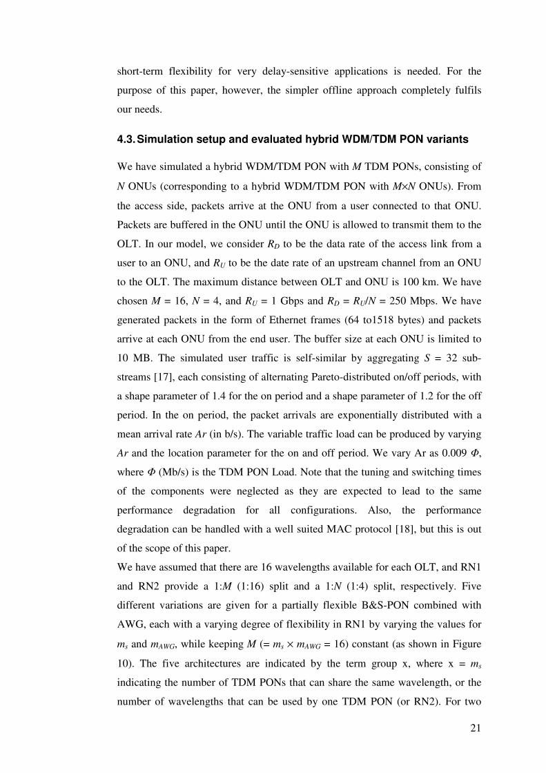
4.3. Simulation setup and evaluated hybrid WDM/TDM PON variants
We have simulated a hybrid WDM/TDM PON with M TDM PONs, consisting of
N ONUs (corresponding to a hybrid WDM/TDM PON with M×N ONUs). From
the access side, packets arrive at the ONU from a user connected to that ONU.
Packets are buffered in the ONU until the ONU is allowed to transmit them to the
OLT. In our model, we consider RD to be the data rate of the access link from a
user to an ONU, and RU to be the date rate of an upstream channel from an ONU
to the OLT. The maximum distance between OLT and ONU is 100 km. We have
chosen M = 16, N = 4, and RU = 1 Gbps and RD = RU/N = 250 Mbps. We have
generated packets in the form of Ethernet frames (64 to1518 bytes) and packets
arrive at each ONU from the end user. The buffer size at each ONU is limited to
10 MB. The simulated user traffic is self-similar by aggregating S = 32 sub-
streams [17], each consisting of alternating Pareto-distributed on/off periods, with
a shape parameter of 1.4 for the on period and a shape parameter of 1.2 for the off
period. In the on period, the packet arrivals are exponentially distributed with a
mean arrival rate Ar (in b/s). The variable traffic load can be produced by varying
Ar and the location parameter for the on and off period. We vary Ar as 0.009 Φ,
where Φ (Mb/s) is the TDM PON Load. Note that the tuning and switching times
of the components were neglected as they are expected to lead to the same
performance degradation for all configurations. Also, the performance
degradation can be handled with a well suited MAC protocol [18], but this is out
of the scope of this paper.
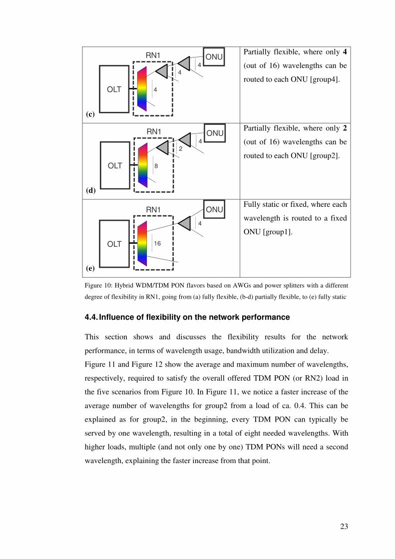
We have assumed that there are 16 wavelengths available for each OLT, and RN1
and RN2 provide a 1:M (1:16) split and a 1:N (1:4) split, respectively. Five
different variations are given for a partially flexible B&S-PON combined with
AWG, each with a varying degree of flexibility in RN1 by varying the values for
ms and mAWG, while keeping M (= ms × mAWG = 16) constant (as shown in Figure
10). The five architectures are indicated by the term group x, where x = ms
indicating the number of TDM PONs that can share the same wavelength, or the
number of wavelengths that can be used by one TDM PON (or RN2). For two
22
extreme cases, this architecture is reduced to the broadcast-and-select PON
(mAWG = 1, Figure 10(a)) and wavelength-split PON (ms = 1, Figure 10(e)). The
broadcast-and-select PON of Figure 10(a) was discussed in Section 2.1.1 and also
depicted in Figure 3(a). It provides full flexibility and any of the subscribers can
use any of the available wavelengths, i.e. 16 in the Figure 10. The architecture of
Figure 10(b-d) was described in Section 2.3.1 and similar to the one in Figure
5(a). In Figure 10(b-d), only 8, 4 or 2 specific wavelengths can be used by a TDM
PON or the group of ONUs sharing the last mile passive splitter in RN2.
Therefore, any wavelength can only be shared by a limited number (8, 4 or 2) of
TDM PONs. The wavelength-split PON of Figure 10(e) was presented in Section
2.2.1 and on Figure 4. It has no flexibility, as all ONUs can only use their
dedicated wavelengths.
Note that in both Figure 4 and Figure 5(a), a separate AWG was depicted for
uplink and downlink. For simplicity reasons, however, Figure 10 shows an
architecture with uplink and downlink wavelengths in the same band so that only
one AWG can be used. In the architectures of Figure 10, an increasing flexibility
corresponds to an increasing insertion loss (and by consequence a shorter reach).
(a)
OLT 16
ONU
4
RN1
Fully flexible, where each
wavelength can be routed to
each ONU [group16].
(b)
OLT 2
ONU4
8
RN1
Partially flexible, where only 8
(out of 16) wavelengths can be
routed to each ONU [group8].
23
(c)
OLT 4
ONU4
4
RN1
Partially flexible, where only 4
(out of 16) wavelengths can be
routed to each ONU [group4].
(d)
OLT 8
ONU4
2
RN1
Partially flexible, where only 2
(out of 16) wavelengths can be
routed to each ONU [group2].
(e)
OLT 16
ONU
4
RN1
Fully static or fixed, where each
wavelength is routed to a fixed
ONU [group1].
Figure 10: Hybrid WDM/TDM PON flavors based on AWGs and power splitters with a different
degree of flexibility in RN1, going from (a) fully flexible, (b-d) partially flexible, to (e) fully static
4.4. Influence of flexibility on the network performance
This section shows and discusses the flexibility results for the network
performance, in terms of wavelength usage, bandwidth utilization and delay.
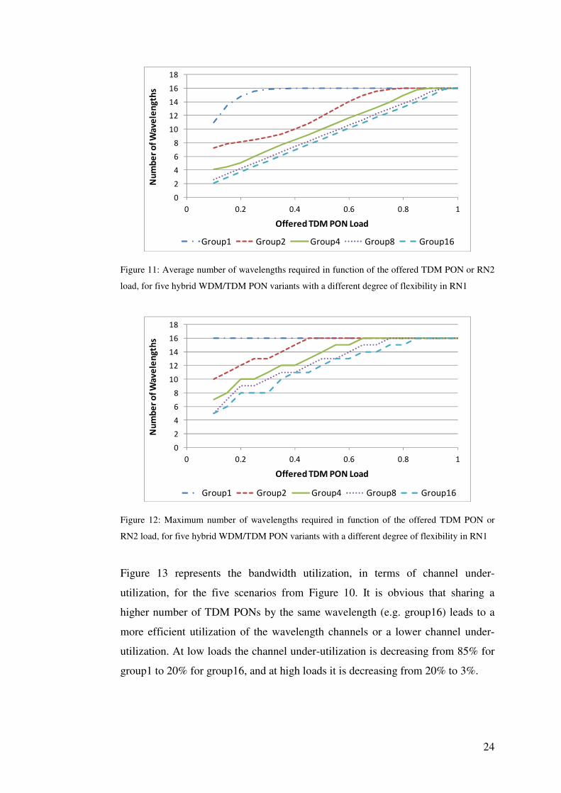
Figure 11 and Figure 12 show the average and maximum number of wavelengths,
respectively, required to satisfy the overall offered TDM PON (or RN2) load in
the five scenarios from Figure 10. In Figure 11, we notice a faster increase of the
average number of wavelengths for group2 from a load of ca. 0.4. This can be
explained as for group2, in the beginning, every TDM PON can typically be
served by one wavelength, resulting in a total of eight needed wavelengths. With
higher loads, multiple (and not only one by one) TDM PONs will need a second
wavelength, explaining the faster increase from that point.
24
0
2
4
6
8
10
12
14
16
18
0 0.2 0.4 0.6 0.8 1
Nu
mb
er
of
Wa
ve
len
gth
s
Offered TDM PON Load
Group1 Group2 Group4 Group8 Group16
Figure 11: Average number of wavelengths required in function of the offered TDM PON or RN2
load, for five hybrid WDM/TDM PON variants with a different degree of flexibility in RN1
0
2
4
6
8
10
12
14
16
18
0 0.2 0.4 0.6 0.8 1
Nu
mb
er
of
Wa
ve
len
gth
s
Offered TDM PON Load
Group1 Group2 Group4 Group8 Group16
Figure 12: Maximum number of wavelengths required in function of the offered TDM PON or
RN2 load, for five hybrid WDM/TDM PON variants with a different degree of flexibility in RN1
Figure 13 represents the bandwidth utilization, in terms of channel under-
utilization, for the five scenarios from Figure 10. It is obvious that sharing a
higher number of TDM PONs by the same wavelength (e.g. group16) leads to a
more efficient utilization of the wavelength channels or a lower channel under-
utilization. At low loads the channel under-utilization is decreasing from 85% for
group1 to 20% for group16, and at high loads it is decreasing from 20% to 3%.
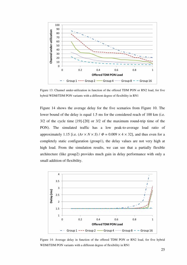
25
0
10
20
30
40
50
60
70
80
90
100
0 0.2 0.4 0.6 0.8 1
Ch
an
ne
l un
de
r-u
tili
zati
on
Offered TDM PON Load
Group 1 Group 2 Group 4 Group 8 Group 16
Figure 13: Channel under-utilization in function of the offered TDM PON or RN2 load, for five
hybrid WDM/TDM PON variants with a different degree of flexibility in RN1
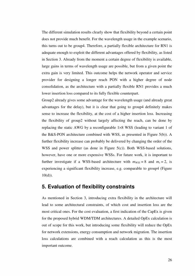
Figure 14 shows the average delay for the five scenarios from Figure 10. The
lower bound of the delay is equal 1.5 ms for the considered reach of 100 km (i.e.
3/2 of the cycle time [19]-[20] or 3/2 of the maximum round-trip time of the
PON). The simulated traffic has a low peak-to-average load ratio of
approximately 1.15 [i.e. (Ar × N × S) / Φ = 0.009 × 4 × 32], and thus even for a
completely static configuration (group1), the delay values are not very high at
high load. From the simulation results, we can see that a partially flexible
architecture (like group2) provides much gain in delay performance with only a
small addition of flexibility.
1
1.5
2
2.5
3
3.5
4
0 0.2 0.4 0.6 0.8 1
De
lay
(m
s)
Offered TDM PON Load
Group 1 Group 2 Group 4 Group 8 Group 16
Figure 14: Average delay in function of the offered TDM PON or RN2 load, for five hybrid
WDM/TDM PON variants with a different degree of flexibility in RN1
26
The different simulation results clearly show that flexibility beyond a certain point
does not provide much benefit. For the wavelength usage in the example scenario,
this turns out to be group4. Therefore, a partially flexible architecture for RN1 is
adequate enough to exploit the different advantages offered by flexibility, as listed
in Section 3. Already from the moment a certain degree of flexibility is available,
large gains in terms of wavelength usage are possible, but from a given point the
extra gain is very limited. This outcome helps the network operator and service
provider for designing a longer reach PON with a higher degree of node
consolidation, as the architecture with a partially flexible RN1 provides a much
lower insertion loss compared to its fully flexible counterpart.
Group2 already gives some advantage for the wavelength usage (and already great
advantages for the delay), but it is clear that going to group4 definitely makes
sense to increase the flexibility, at the cost of a higher insertion loss. Increasing
the flexibility of group2 without largely affecting the reach, can be done by
replacing the static AWG by a reconfigurable 1×8 WSS (leading to variant 1 of
the B&S-PON architecture combined with WSS, as presented in Figure 5(b)). A
further flexibility increase can probably be delivered by changing the order of the
WSS and power splitter (as done in Figure 5(c)). Both WSS-based solutions,
however, have one or more expensive WSSs. For future work, it is important to
further investigate if a WSS-based architecture with mWSS = 8 and ms = 2, is
experiencing a significant flexibility increase, e.g. comparable to group4 (Figure
10(d)).
5. Evaluation of flexibility constraints
As mentioned in Section 3, introducing extra flexibility in the architecture will
lead to some architectural constraints, of which cost and insertion loss are the
most critical ones. For the cost evaluation, a first indication of the CapEx is given
for the proposed hybrid WDM/TDM architectures. A detailed OpEx calculation is
out of scope for this work, but introducing some flexibility will reduce the OpEx
for network extensions, energy consumption and network migration. The insertion
loss calculations are combined with a reach calculation as this is the most
important outcome.
27
For the evaluations below, we have assumed three scenarios with Wu,d = 32
wavelength pairs at 10 Gbps, and varying values for the RN1 split M and the RN2
split N. The chosen values for M and N, together with the resulting number of
subscribers per OLT and the sustainable bandwidth per subscriber are summarized
in Table 1.
Table 1: Considered scenarios for the equipment cost and insertion loss evaluation
M N # subscribers
per OLT
Sustainable
bandwidth
Scenario 1 16 32 512 625 Mbps
Scenario 2 32 16 512 625 Mbps
Scenario 3 32 32 1024 312.5 Mbps
As an addition to Table 1, we want to make two extra remarks. First of all, in
Section 2.3.2, it was mentioned that partially flexible architectures without
multicasting are only of importance if W > M, and this means that only scenario 1
is useful for them (scenario 2 and 3, with W = M, are also added in the evaluation
results of these extended WS-PONs, but they are much less relevant as their
functionality is almost identical to a pure WS-PON, but at a higher cost).
Secondly, for the partially flexible architectures with multicasting, there is an
extra design parameter in RN1 as the 1:M split is done in two different stages (see
Figure 5). Here, we assume that the splitting ratio of the first stage (resp. mAWG,
mWSS, ms) is always equal to 4.
5.1. Cost
In this section, two equipment cost evaluations are made. A first evaluation
compares the equipment cost between the eight different hybrid WDM/TDM PON
architectures discussed in Section 2 for the three scenarios presented in Table 1. In
a second step, a more detailed evaluation is made for the different partially
flexible hybrid WDM/TDM PON architectural options.
The eight architectures considered for the first evaluation are B&S-PON, WR-
PON (i.e. fully flexible, cf. Figure 3), WS-PON (i.e. fully static, cf. Figure 4),
B&S-PON, combined with AWG or WSS (i.e. partially flexible with multicasting,
cf. Figure 5) and WS-PON, combined with extra wavelength combiners or WSS
(i.e. partially flexible without multicasting, cf. Figure 6). Table 2 gives an
overview of the assumed cost figures of the most important components used in
28
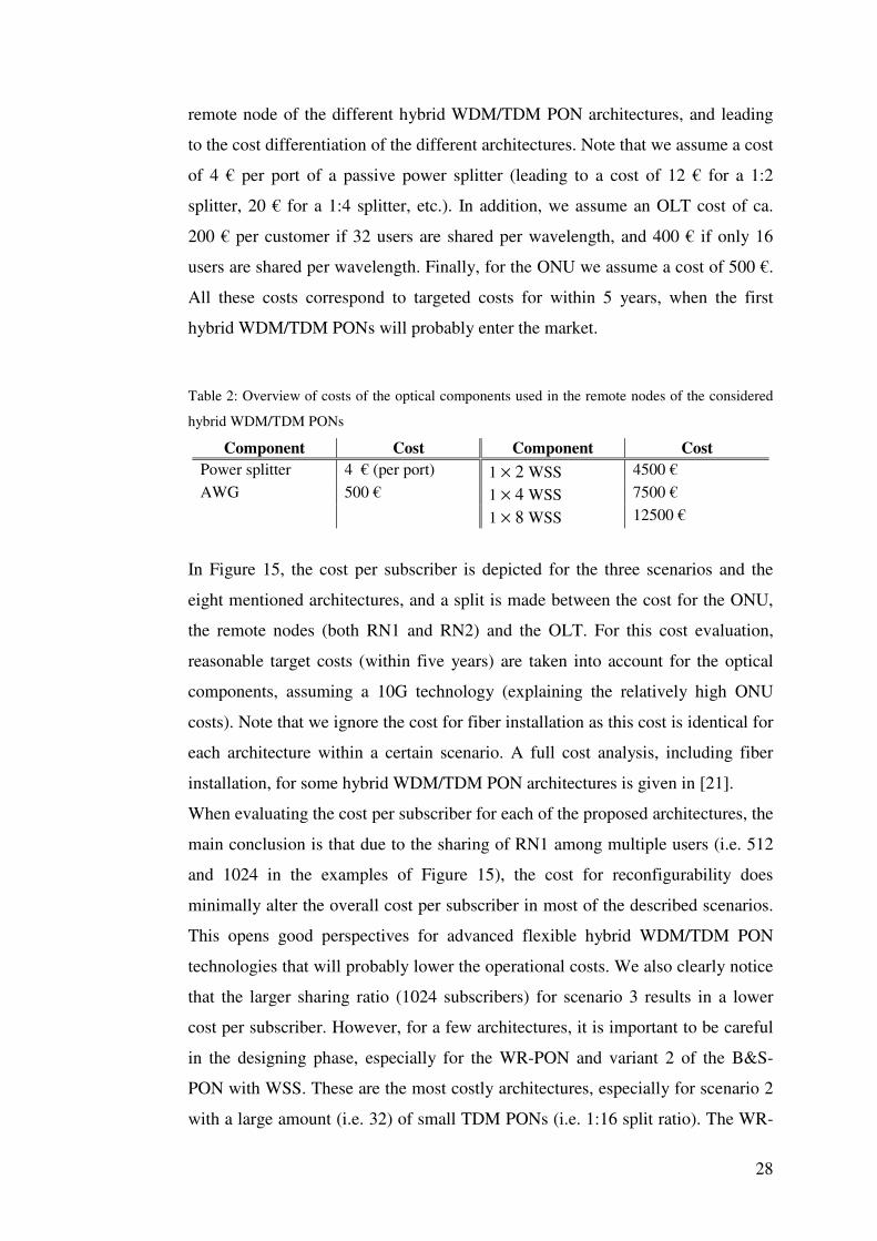
remote node of the different hybrid WDM/TDM PON architectures, and leading
to the cost differentiation of the different architectures. Note that we assume a cost
of 4 € per port of a passive power splitter (leading to a cost of 12 € for a 1:2
splitter, 20 € for a 1:4 splitter, etc.). In addition, we assume an OLT cost of ca.
200 € per customer if 32 users are shared per wavelength, and 400 € if only 16
users are shared per wavelength. Finally, for the ONU we assume a cost of 500 €.
All these costs correspond to targeted costs for within 5 years, when the first
hybrid WDM/TDM PONs will probably enter the market.
Table 2: Overview of costs of the optical components used in the remote nodes of the considered
hybrid WDM/TDM PONs
Component Cost Component Cost
Power splitter 4 € (per port) 1 × 2 WSS 4500 €
AWG 500 € 1 × 4 WSS 7500 €
1 × 8 WSS 12500 €
In Figure 15, the cost per subscriber is depicted for the three scenarios and the
eight mentioned architectures, and a split is made between the cost for the ONU,
the remote nodes (both RN1 and RN2) and the OLT. For this cost evaluation,
reasonable target costs (within five years) are taken into account for the optical
components, assuming a 10G technology (explaining the relatively high ONU
costs). Note that we ignore the cost for fiber installation as this cost is identical for
each architecture within a certain scenario. A full cost analysis, including fiber
installation, for some hybrid WDM/TDM PON architectures is given in [21].
When evaluating the cost per subscriber for each of the proposed architectures, the
main conclusion is that due to the sharing of RN1 among multiple users (i.e. 512
and 1024 in the examples of Figure 15), the cost for reconfigurability does
minimally alter the overall cost per subscriber in most of the described scenarios.
This opens good perspectives for advanced flexible hybrid WDM/TDM PON
technologies that will probably lower the operational costs. We also clearly notice
that the larger sharing ratio (1024 subscribers) for scenario 3 results in a lower
cost per subscriber. However, for a few architectures, it is important to be careful
in the designing phase, especially for the WR-PON and variant 2 of the B&S-
PON with WSS. These are the most costly architectures, especially for scenario 2
with a large amount (i.e. 32) of small TDM PONs (i.e. 1:16 split ratio). The WR-
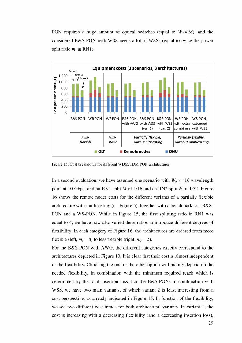
29
PON requires a huge amount of optical switches (equal to Wd × M), and the
considered B&S-PON with WSS needs a lot of WSSs (equal to twice the power
split ratio ms at RN1).
0
200
400
600
800
1,000
1,200
B&S PON WR PON WS PON B&S PON,
with AWG
B&S PON,
with WSS
(var. 1)
B&S PON,
with WSS
(var. 2)
WS-PON,
with extra
combiners
WS-PON,
extended
with WSS
Co
st p
er
sub
scri
be
r (€
)
Equipment costs (3 scenarios, 8 architectures)
OLT Remote nodes ONU
Scen.1
Scen.2
Scen.3
Partially flexible,
with multicasting
Partially flexible,
without multicasting
Fully
flexible
Fully
static
Figure 15: Cost breakdown for different WDM/TDM PON architectures
In a second evaluation, we have assumed one scenario with Wu,d = 16 wavelength
pairs at 10 Gbps, and an RN1 split M of 1:16 and an RN2 split N of 1:32. Figure
16 shows the remote nodes costs for the different variants of a partially flexible
architecture with multicasting (cf. Figure 5), together with a benchmark to a B&S-
PON and a WS-PON. While in Figure 15, the first splitting ratio in RN1 was
equal to 4, we have now also varied these ratios to introduce different degrees of
flexibility. In each category of Figure 16, the architectures are ordered from more
flexible (left, ms = 8) to less flexible (right, ms = 2).
For the B&S-PON with AWG, the different categories exactly correspond to the
architectures depicted in Figure 10. It is clear that their cost is almost independent
of the flexibility. Choosing the one or the other option will mainly depend on the
needed flexibility, in combination with the minimum required reach which is
determined by the total insertion loss. For the B&S-PONs in combination with
WSS, we have two main variants, of which variant 2 is least interesting from a
cost perspective, as already indicated in Figure 15. In function of the flexibility,
we see two different cost trends for both architectural variants. In variant 1, the
cost is increasing with a decreasing flexibility (and a decreasing insertion loss),
30
due to the use of WSS with a higher (up to 1×8) switching capability. In variant 2,
the cost is increasing with an increasing flexibility, due to the need for a higher
number of WSSs (equal to ms).
0
20
40
60
80
100
120
140
160
180
B&S
PON
B&S PON,
with AWG
B&S PON,
with WSS
(var. 1)
B&S PON,
with WSS
(var. 2)
WS
PON
Co
st p
er
sub
scri
be
r (€
)
Remote Nodes: equipment costs (W = 16, M= 16, N = 32)
ms=8,
mAWG=2
ms=4,
mAWG=4
ms=2,
mAWG=8
ms=8,
mWSS=2
ms=4,
mWSS=4
ms=2,
mWSS=8
ms=8,
mWSS=2
ms=4,
mWSS=4
ms=2,
mWSS=8
Figure 16: Remote nodes costs for different partially flexible hybrid WDM/TDM PON
architectures, with multicasting (and compared to B&S-PON and WS-PON).
5.2. Insertion loss and reach
In this section we calculate the insertion loss and the optical reach possible for the
eight considered hybrid WDM/TDM PON architectures. Table 3 gives an
overview of the assumed insertion losses of the most important components used
in the different hybrid WDM/TDM PON architectures. Note that we assume a
3.5 dB loss per 1:2 power split instead of the theoretical loss of 3 dB, as the latter
is never attained in real implementations. For the AWG we assume a channel
spacing of 100 GHz which is sufficient for a maximum of 32 wavelengths per
direction. For AWGs with a 50 GHz spacing, however, the insertion loss will
increase with roughly 1 dB. Further, an optical component can be coupled by
using a connector (ca. 0.5 dB) or a splice (ca. 0.1 dB). In our calculations, we use
an average connector loss of 0.25 dB.
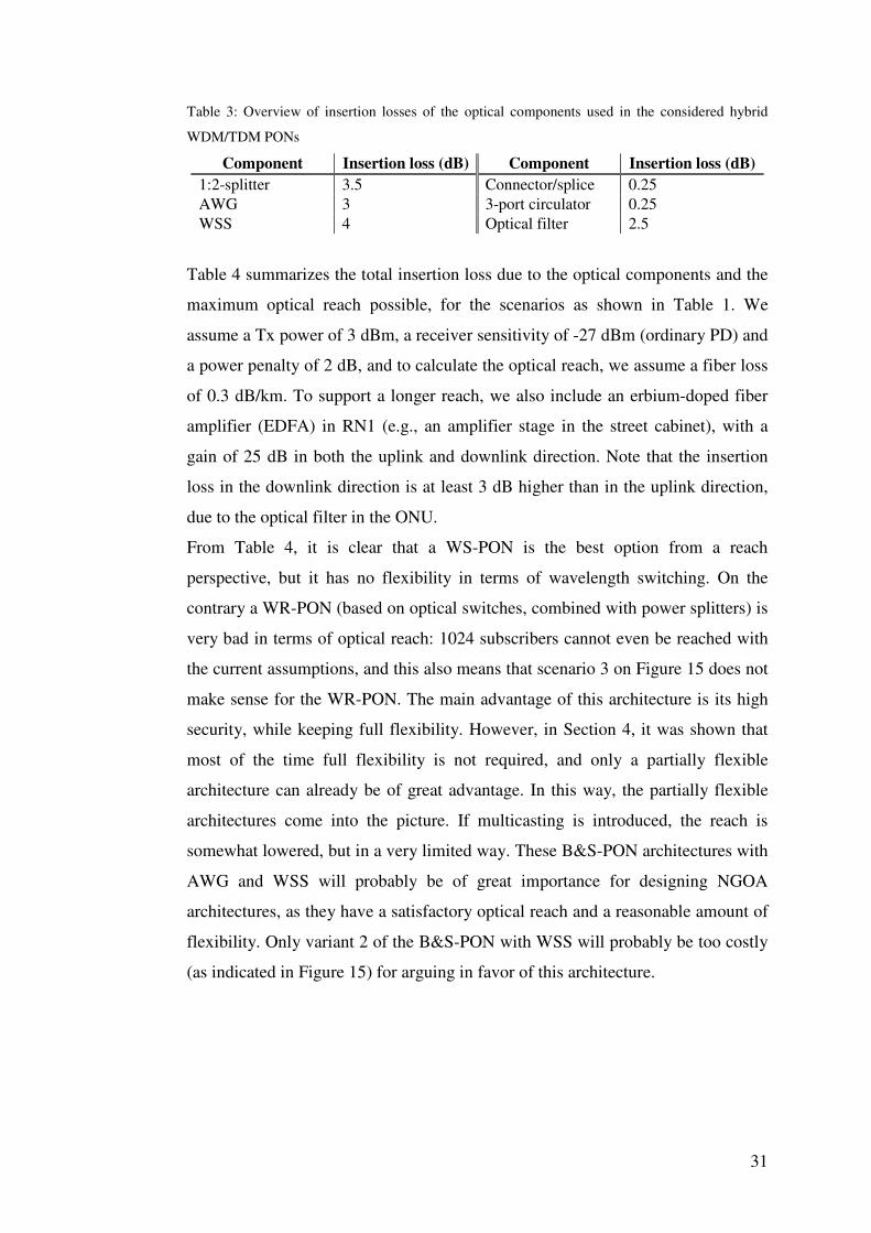
31
Table 3: Overview of insertion losses of the optical components used in the considered hybrid
WDM/TDM PONs
Component Insertion loss (dB) Component Insertion loss (dB)
1:2-splitter 3.5 Connector/splice 0.25
AWG 3 3-port circulator 0.25
WSS 4 Optical filter 2.5
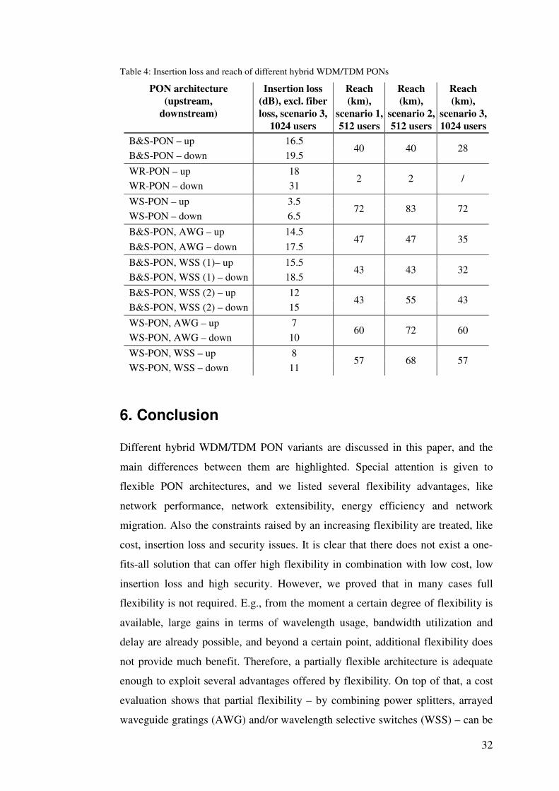
Table 4 summarizes the total insertion loss due to the optical components and the
maximum optical reach possible, for the scenarios as shown in Table 1. We
assume a Tx power of 3 dBm, a receiver sensitivity of -27 dBm (ordinary PD) and
a power penalty of 2 dB, and to calculate the optical reach, we assume a fiber loss
of 0.3 dB/km. To support a longer reach, we also include an erbium-doped fiber
amplifier (EDFA) in RN1 (e.g., an amplifier stage in the street cabinet), with a
gain of 25 dB in both the uplink and downlink direction. Note that the insertion
loss in the downlink direction is at least 3 dB higher than in the uplink direction,
due to the optical filter in the ONU.
From Table 4, it is clear that a WS-PON is the best option from a reach
perspective, but it has no flexibility in terms of wavelength switching. On the
contrary a WR-PON (based on optical switches, combined with power splitters) is
very bad in terms of optical reach: 1024 subscribers cannot even be reached with
the current assumptions, and this also means that scenario 3 on Figure 15 does not
make sense for the WR-PON. The main advantage of this architecture is its high
security, while keeping full flexibility. However, in Section 4, it was shown that
most of the time full flexibility is not required, and only a partially flexible
architecture can already be of great advantage. In this way, the partially flexible
architectures come into the picture. If multicasting is introduced, the reach is
somewhat lowered, but in a very limited way. These B&S-PON architectures with
AWG and WSS will probably be of great importance for designing NGOA
architectures, as they have a satisfactory optical reach and a reasonable amount of
flexibility. Only variant 2 of the B&S-PON with WSS will probably be too costly
(as indicated in Figure 15) for arguing in favor of this architecture.
32
Table 4: Insertion loss and reach of different hybrid WDM/TDM PONs
PON architecture
(upstream,
downstream)
Insertion loss
(dB), excl. fiber
loss, scenario 3,
1024 users
Reach
(km),
scenario 1,
512 users
Reach
(km),
scenario 2,
512 users
Reach
(km),
scenario 3,
1024 users
B&S-PON – up 16.5 40 40 28
B&S-PON – down 19.5
WR-PON – up 18 2 2 /
WR-PON – down 31
WS-PON – up 3.5 72 83 72
WS-PON – down 6.5
B&S-PON, AWG – up 14.5 47 47 35
B&S-PON, AWG – down 17.5
B&S-PON, WSS (1)– up 15.5 43 43 32
B&S-PON, WSS (1) – down 18.5
B&S-PON, WSS (2) – up 12 43 55 43
B&S-PON, WSS (2) – down 15
WS-PON, AWG – up 7 60 72 60
WS-PON, AWG – down 10
WS-PON, WSS – up 8 57 68 57
WS-PON, WSS – down 11
6. Conclusion
Different hybrid WDM/TDM PON variants are discussed in this paper, and the
main differences between them are highlighted. Special attention is given to
flexible PON architectures, and we listed several flexibility advantages, like
network performance, network extensibility, energy efficiency and network
migration. Also the constraints raised by an increasing flexibility are treated, like
cost, insertion loss and security issues. It is clear that there does not exist a one-
fits-all solution that can offer high flexibility in combination with low cost, low
insertion loss and high security. However, we proved that in many cases full
flexibility is not required. E.g., from the moment a certain degree of flexibility is
available, large gains in terms of wavelength usage, bandwidth utilization and
delay are already possible, and beyond a certain point, additional flexibility does
not provide much benefit. Therefore, a partially flexible architecture is adequate
enough to exploit several advantages offered by flexibility. On top of that, a cost
evaluation shows that partial flexibility – by combining power splitters, arrayed
waveguide gratings (AWG) and/or wavelength selective switches (WSS) – can be
33
added to a hybrid WDM/TDM PON architecture without extremely affecting the
final equipment cost per subscriber and probably lowering the operational cost.
Moreover, using AWGs or WSSs in the first remote node of a hybrid WDM/TDM
PON architecture leads to a better reach and security than for a fully flexible
broadcast-and-select PON architecture only using power splitters. Therefore,
considering all the selection criteria like flexibility, cost, reach and data security, a
well-designed partially flexible hybrid WDM/TDM PON based on AWGs and/or
WSSs provides important advantages. This opens good perspectives for offering
dynamic capacity allocation in novel (partially) flexible hybrid WDM/TDM PON
architectures.
Several discussed flavors in this paper, however, are long-term solutions that still
need further research in a laboratory environment before they can be considered
for commercial use. Moreover, the long-term flexibility advantages, like network
extensibility and network migration, should be studied in more detail to quantify
their importance in terms of improved network performance as well as reduced
operational costs.
7. Acknowledgements
The research leading to these results has received funding from the European
Community's Seventh Framework Programme (FP7/2007-2013) under grant
agreements n° 212352 (ICT-ALPHA) and n° 249025 (ICT-OASE).
8. References
[1] IEEE 802.3ah task force home page [Online]. Available: http://www.ieee802.org/3/efm.
[2] ITU-T G.984.x series of recommendations [Online]. Available: http://www.itu.int/rec/T-REC-
G/e.
[3] T. Koonen, “Fibre to the Home/Fibre to the Premises: what, where, and when?”, Proc. of the
IEEE, Vol. 94, No. 5, May 2006, pp. 911-934.
[4] 249025-ICT OASE Project, Requirements for European Next-Generation Optical Access
Networks, D2.1.
[5] H. Rohde, S. Smolorz, and E. Gottwald, “Next Generation Ultra High Capacity PONs”, 23rd
Annual Meeting of the IEEE Photonics Society, Denver, Colorado, USA, Nov. 7-11, 2010.
[6] N.C. Tran, H.D. Jung, C. Okonkwo, E. Tangdiongga, and T. Koonen, “ARON: A SOA Array-
based WDM-TDM Reconfigurable Optical Access Network”, Future Network & Mobile
Summit 2010, Florence, Italy, Jun. 16-18, 2010.
34
[7] H.D. Jung, N.C. Tran, E. Tangdiongga, and T. Koonen, “New Architecture for reconfigurable
WDM-PON Networks based on SOA Gating Array”, 9th International Conference on Optical
Internet (COIN), Korea, Jul. 11-14, 2010.
[8] G. Das, B. Lannoo, H.-D. Jung, T. Koonen, D. Colle, M. Pickavet, and P. Demeester, “A New
Architecture and MAC Protocol for Fully Flexible Hybrid WDM/TDM PON”, ECOC 2009,
Vienna, Austria, Sep. 20-24, 2009, paper P6.28.
[9] C. Bock, J. Prat, and S. D. Walker, “Hybrid WDM/TDM PON Using the AWG FSR and
Featuring Centralized Light Generation and Dynamic Bandwidth Allocation”, Journal of
Lightwave Technology, vol. 23, no. 12, Dec. 2005, pp. 3981-3988.
[10] N. Calabretta, M. Presi, R. Proietti, G. Contestabile, and E. Ciaramella, “A Bidirectional
WDM/TDM-PON Using DPSK Downstream Signals and a Narrowband AWG”, IEEE
Photonics Technology Letters, Vol. 19, No. 16, Aug. 2007, pp. 1227-1229.
[11] R. Jensen, and A. Lord, “Novel Non-Blocking Low Loss Scalable WSS Architecture”,
OFC/NFOEC 2008, San Diego, California, USA, Feb. 24-28, 2008, paper OthA6.
[12] G. Das, B. Lannoo, D. Colle, M. Pickavet, and P. Demeester, “A Hybrid WDM/TDM PON
Architecture Using Wavelength Selective Switches”, 4th IEEE International Symposium on
Advanced Networks and Telecommunication Systems (ANTS 2010), Mumbai, India, Dec. 16-
18, 2010.
[13] M. P. McGarry, and M. Reisslein, “Bandwidth management for WDM EPONS,” Journal of
Optical Networking, Vol. 5, No. 9, Sep. 2006, pp. 637-654.
[14] A. R. Dhaini, C. M. Assi, and A. Shami, “Dynamic wavelength and bandwidth allocation in
hybrid TDM/WDM EPON networks”, Journal of Lightwave Technology, Vol. 25, No. 1, Jan.
2007, pp. 277-286.
[15] M. P. McGarry, M. Reisslein, C. J. Colbourn, M. Maier, F. Aurzada, and M. Scheutzow,
“Just-in-time scheduling for multichannel EPONs”, Journal of Lightwave Technology, Vol.
26, No. 10, May 2008, pp. 1204–1216.
[16] K. Kanonakis, and I. Tomkos, “Improving the efficiency of online upstream scheduling and
wavelength assignment in hybrid WDM/TDMA EPON networks”, IEEE Journal on selected
areas in Communications, Vol. 28, No. 6, Aug. 2010, pp. 838-848.
[17] W. Willinger, M. Taqqu, R. Sherman, and D. Wilson. “Self-similarity through highvariability:
statistical analysis of Ethernet LAN traffic at the source level”, Proc., ACM SIGCOMM '95,
Cambridge, UK, Aug. 1995, pp. 100-113.
[18] J. Zhang, and N. Ansari, “Scheduling Hybrid WDM/TDM Passive Optical Networks with
Nonzero Laser Tuning Time”, IEEE/ACM Transactions on Networking, Vol. 19, No. 4, Aug.
2011, pp 1014 - 1027.
[19] C. G. Park, D. H. Han, and K. W. Rim, “Packet Delay Analysis of Symmetric Gated Polling
System for DBA Scheme in an EPON”, Telecommunication Systems Journal, Vol. 30, No. 1-
3, 2005, pp. 13-34.
[20] B. Lannoo, L. Verslegers, D. Colle, M. Pickavet, M. Gagnaire, and P. Demeester, “Analytical
Model for the IPACT Dynamic Bandwidth Allocation Algorithm for EPONs”, Journal of
Optical Networking, Vol. 6, No. 6, Jun. 2007, pp. 677-688.

35
[21] B. Lannoo, G. Das, M. De Groote, D. Colle, M. Pickavet, and P. Demeester, “Techno-
economic feasibility study of different WDM/TDM PON architectures”, 12th International
Conference on Transparent Optical Networks (ICTON 2010), Munich, Germany, Jun. 27-Jul.
1, 2010.