Embed Size (px)
Citation preview

Novel Finger-like Soft PneumaticActuators for Affective Movement
by
Mohammadreza Memarian
A thesispresented to the University of Waterloo
in fulfillment of thethesis requirement for the degree of
Master of Applied Sciencein
Electrical & Computer Engineering
Waterloo, Ontario, Canada, 2015
c© Mohammadreza Memarian 2015

I hereby declare that I am the sole author of this thesis. This is a true copy of the thesis,including any required final revisions, as accepted by my examiners.
I understand that my thesis may be made electronically available to the public.
ii

Abstract
The ability to communicate emotion through movement is an important element toenable engaging social human-robot interaction. It has been shown that humans are capa-ble of conveying emotion through hand and arm movements alone. Thus, simple roboticsstructures might be capable of emotion conveyance. In this thesis, the design and imple-mentation of a finger-like robotic structure capable of performing movements that conveyemotion is investigated. First, the requirements for such a mechanism are derived directlyfrom human affective movement dynamics, coupled with application-specific constraints.Comparative analysis is performed on various actuation options based on these require-ments. Studies suggest that fast dynamic motion is required for the conveyance of manyemotions. Therefore, the analysis focused on determining actuation options that can pro-duce controllable finger-like motion with fast dynamics. A class of pneumatic actuatorscalled soft pneumatic artificial muscles (SPAMs) were determined to fit the requirementsfor finger-like affective motion better than the other available actuator options.
SPAMs are a type of pneumatic actuator that provides customizable motion trajectoriesin three dimensional space without the need for rigid links or a transmission mechanism.The motion of these actuators can be designed to be similar to the motion of the humanfinger. Their motion also achieves high velocities and accelerations. In addition, SPAMsprovide high power to weight ratios and are compliant, making them suitable for interactionwith human users.
In this thesis, a novel design for producing SPAMs, named wrapped SPAMs (WSPAMs)is introduced. Unlike previous SPAM designs, the production process of WSPAM is highlyrepeatable, while the motion trajectory can be easily tailored at the design stage. Amodel is presented for predicting the steady state angular displacement of the WSPAMactuator based on its geometrical parameters and the elasticity of the materials used inits production. The model is validated by experimental analysis. Two sets of experimentsare designed and presented. The first set enables the estimation of the model parameters.In the second set of experiments, the estimated parameters are used to model WSPAMsthrough the possible range of design parameters. Six WSPAMs with design parameterswithin the physical limitations are constructed. Comparison of their performance againstthe modeled results is presented, and shows that the model is capable of estimating theperformance of WSPAM within the physical limitations of its design.
Finally, a pneumatic circuit and a closed-loop controller for the finger-like movementof these soft pneumatic actuators is developed. An innovative approach, which uses agyroscopic sensor, is used to add feedback on the position of these actuators and make
iii

closed-loop control possible. Additionally, a simple and low-cost solution is designed tosignificantly improve the noisy behavior of the existing pneumatic driving mechanisms.The proposed controller design is validated on physical SPAM prototypes. Experimentalresults demonstrate the performance of the pneumatic and control system for the actuator,and its ability to track human movement trajectories with affective content.
iv

Acknowledgements
I would like to thank my supervisors, Professor Dana Kulic and Professor Rob Gorbet,for the patient guidance, encouragement and advice they provided throughout my time astheir student. I have been extremely lucky to have supervisors who cared so much aboutmy work, and who responded to my questions and queries so promptly. I would like toalso thank Ali Samadani and Matt Borland for their help on various chapters of this work.
Lastly, I would like to thank the Robotics and Biology Laboratory from TechnischeUniversitat Berlin for providing us with their novel PneuFlex pneumatic actuators.
v

Dedication
This is dedicated to my family and the love of my life.
vi

Table of Contents
List of Tables ix
List of Figures x
1 Introduction 1
2 IFLS Design Requirements 5
2.1 Analysis of Human Hand Affective Motion Trajectories . . . . . . . . . . . 5
2.2 Design Requirements . . . . . . . . . . . . . . . . . . . . . . . . . . . . . . 13
2.2.1 Application-Specific Requirements (Interactive Architecture) . . . . 14
2.2.2 Human Interaction Requirements . . . . . . . . . . . . . . . . . . . 14
2.2.3 Dynamic Requirements . . . . . . . . . . . . . . . . . . . . . . . . . 15
2.3 Summary of Design Requirements . . . . . . . . . . . . . . . . . . . . . . . 19
3 Mechanical System Design 21
3.1 Conventional Mechanical Designs . . . . . . . . . . . . . . . . . . . . . . . 21
3.1.1 Actuators . . . . . . . . . . . . . . . . . . . . . . . . . . . . . . . . 23
3.1.2 Transmission . . . . . . . . . . . . . . . . . . . . . . . . . . . . . . 33
3.2 Soft Pneumatic Artificial Muscles . . . . . . . . . . . . . . . . . . . . . . . 35
3.2.1 Background . . . . . . . . . . . . . . . . . . . . . . . . . . . . . . . 35
3.2.2 SPAM Requirement Analysis . . . . . . . . . . . . . . . . . . . . . 37
3.3 Mechanical System Design Summary . . . . . . . . . . . . . . . . . . . . . 47
vii

4 SPAM Control 49
4.1 Proposed Approach . . . . . . . . . . . . . . . . . . . . . . . . . . . . . . . 50
4.1.1 PneuFlex Actuator design modification . . . . . . . . . . . . . . . . 50
4.1.2 Electromechanical Driving Mechanism . . . . . . . . . . . . . . . . 51
4.1.3 Controller . . . . . . . . . . . . . . . . . . . . . . . . . . . . . . . . 56
4.2 Experiments . . . . . . . . . . . . . . . . . . . . . . . . . . . . . . . . . . . 57
4.2.1 Reference Signal . . . . . . . . . . . . . . . . . . . . . . . . . . . . 57
4.2.2 Control System Requirements . . . . . . . . . . . . . . . . . . . . . 58
4.2.3 Controller Results . . . . . . . . . . . . . . . . . . . . . . . . . . . . 58
5 WSPAM 69
5.1 WSPAM Production Process . . . . . . . . . . . . . . . . . . . . . . . . . . 70
5.2 Steady state modelling . . . . . . . . . . . . . . . . . . . . . . . . . . . . . 76
5.3 Modelling the Effective Young’s Modulus . . . . . . . . . . . . . . . . . . 81
5.4 Experimental Validation . . . . . . . . . . . . . . . . . . . . . . . . . . . . 86
6 Conclusions 92
Bibliography 101
viii

List of Tables
2.1 Maximum and minimum end effector angular velocity in rad/s for joy, anger,and sadness . . . . . . . . . . . . . . . . . . . . . . . . . . . . . . . . . . . 18
2.2 Maximum and minimum end effector angular acceleration in rad/s2 for joy,anger, and sadness . . . . . . . . . . . . . . . . . . . . . . . . . . . . . . . 18
2.3 Required and desired velocity and acceleration of the flexion and extensionmotion of the IFLS . . . . . . . . . . . . . . . . . . . . . . . . . . . . . . . 19
2.4 Summary of Design Requirements . . . . . . . . . . . . . . . . . . . . . . . 20
3.1 End effector orientation, velocity, and acceleration of PneuFlex SPAM design 47
3.2 Comparison of the three most suitable actuation options against the require-ments for the IFLS mechanism . . . . . . . . . . . . . . . . . . . . . . . . 48
4.1 Measured end effector orientation, velocity, and acceleration error, for joy,anger, and sadness trajectories . . . . . . . . . . . . . . . . . . . . . . . . . 62
4.2 Maximum and minimum end effector orientation, velocity, and acceleration,for joy, anger, and sadness trajectories . . . . . . . . . . . . . . . . . . . . 67
ix

List of Figures
1.1 Hylozoic Soil installation; the tentacle mechanism is marked by the red oval.This picture is used with permission from PBAI . . . . . . . . . . . . . . . 2
2.1 Frames of the animation of the human hand performing affective motion . 6
2.2 Kinematic structure of the hand recorded by the data glove showing theorientation and the location of the joints . . . . . . . . . . . . . . . . . . . 7
2.3 The local joint angle and the global end effector orientation of the five fingersduring the trajectory for anger . . . . . . . . . . . . . . . . . . . . . . . . . 10
2.4 The local joint angle and the global end effector orientation of the five fingersduring the trajectory for joy . . . . . . . . . . . . . . . . . . . . . . . . . . 11
2.5 The local joint angle and the global end effector orientation of the five fingersduring the trajectory for sadness . . . . . . . . . . . . . . . . . . . . . . . . 12
2.6 End effector angular velocity of each finger for joy, anger, and sadness . . . 16
2.7 End effector angular acceleration of each finger for joy, anger, and sadness 17
3.1 Sample robotic manipulator design for the IFLS . . . . . . . . . . . . . . . 22
3.2 Illustration of the three main pneumatic actuators in robotics . . . . . . . 28
3.3 PAM dynamic response test apparatus. PAM pressurized to 450kPa shownon left and atmospheric pressure PAM shown on right. . . . . . . . . . . . 30
3.4 End effector orientation of PAM-actuated 1 DOF apparatus . . . . . . . . 31
3.5 End effector angular velocity of PAM-actuated 1 DOF apparatus . . . . . . 32
3.6 End effector angular acceleration of PAM-actuated 1 DOF apparatus . . . 32
3.7 Various transmission mechanisms . . . . . . . . . . . . . . . . . . . . . . . 34
x
3.8 Exapmles of current SPAM designs . . . . . . . . . . . . . . . . . . . . . . 35
3.9 Pneumatic open-loop circuit . . . . . . . . . . . . . . . . . . . . . . . . . . 38
3.10 Absolute end effector orientation of the PneuFlex measured on still images 39
3.11 Frequency content of the velocity of SPAM’s full flexion and extension stepresponse . . . . . . . . . . . . . . . . . . . . . . . . . . . . . . . . . . . . . 41
3.12 SPAM’s full flexion and extension tip orientation response . . . . . . . . . 46
4.1 Components of the modified SPAM-based on the PneuFlex actuator . . . . 51
4.2 The motion frames of the custom built SPAM with curved motion trajectory 51
4.3 The pneumatic circuit for the control of the SPAM actuator . . . . . . . . 54
4.4 Pneumatic low pass filter . . . . . . . . . . . . . . . . . . . . . . . . . . . . 54
4.5 Electrical circuit analogy of the pneumatic circuit with low pass filter andvoltage divider . . . . . . . . . . . . . . . . . . . . . . . . . . . . . . . . . 56
4.6 Pressure-orientation closed-loop controller system for SPAM actuators . . 57
4.7 Reference and experimental end effector orientation for the joy motion andorientation tracking error . . . . . . . . . . . . . . . . . . . . . . . . . . . . 60
4.8 Reference and experimental end effector orientation for the anger motionand orientation tracking error . . . . . . . . . . . . . . . . . . . . . . . . . 61
4.9 Reference and experimental end effector orientation for the sadness motionand orientation tracking error . . . . . . . . . . . . . . . . . . . . . . . . . 62
4.10 Reference and experimental end effector angular velocity for the joy motionand angular velocity tracking error . . . . . . . . . . . . . . . . . . . . . . 64
4.11 Reference and experimental end effector angular velocity for the anger mo-tion and angular velocity tracking error . . . . . . . . . . . . . . . . . . . . 65
4.12 Reference and experimental end effector angular velocity for the sadnessmotion and angular velocity tracking error . . . . . . . . . . . . . . . . . . 66
4.13 Reference vs experimental motion response of the sections that include max-imum and minimum velocities and accelerations . . . . . . . . . . . . . . . 68
5.1 Cuboid WSPAM in the unpressurised and pressurized state. The siliconegap (white) and mesh cover (grey) pair block is shown on the left . . . . . 70
xi

5.2 LEGO-built outer mold with plexiglass covers . . . . . . . . . . . . . . . . 71
5.3 Picture of the alignment procedure and apparatus . . . . . . . . . . . . . . 72
5.4 Pictures of the silicone molding procedure . . . . . . . . . . . . . . . . . . 73
5.5 Pictures of laser-cutting the mesh and aligning the silicone core . . . . . . 74
5.6 Sample laser cut pattern for WSPAM. The red line indicates the lines thelaser cutter needs to cut. . . . . . . . . . . . . . . . . . . . . . . . . . . . 75
5.7 Pictures of the procedure for precisely wrapping the mesh around the core 76
5.8 Parameters of the gap and cover block from top view. W is the thickness ofthe silicone wall, L is the width of the WSPAM with a square cross section. 77
5.9 The physical parameters of the gap and cover block . . . . . . . . . . . . . 78
5.10 The left-hand drawing shows a side view of one cover-gap pair block whenpressurized and the right-hand drawing shows the equivalent spring model.Bending of the block was not depicted for illustration purposes . . . . . . . 82
5.11 Cover section saturation model for the spring constant and the illustrationof the silicone behaviour when pressurized . . . . . . . . . . . . . . . . . . 85
5.12 Gradient Hc (on the left) and Hg (on the right) WSPAMs at rest and pres-surized . . . . . . . . . . . . . . . . . . . . . . . . . . . . . . . . . . . . . . 86
5.13 Simulation and experimental data for Kg in terms of rest heights Hg . . . . 87
5.14 Simulation and experimental data for Kc in terms of rest heights Hc . . . . 88
5.15 Pressurized WSPAMs at 3 different r and 2 different Hb values. Not thatWSPAMs with lower r have higher Hg and achieve greater angular displac-ment but at the cost of a distended, “bloated” appearance. . . . . . . . . . 89
5.16 Simulated and experimental block angular displacement θtip with respect toblock height Hb and block ratio r in 2D . . . . . . . . . . . . . . . . . . . . 90
xii

Chapter 1
Introduction
Research in psychology, animation and human-robot interaction suggests that humansare capable of perceiving and conveying emotion through movement [1, 2]. In robotics,sociable humanoid robots have been studied extensively in the past couple of decades[3, 4, 5, 6]. However, works such as the Kismet robot from MIT [4] mainly focus on facialexpressions, and emotional conveyance through the motion of other parts of the body is notconsidered. Several works (e.g., [7, 8, 9]) investigate the ability of hand and arm movementto convey affect by analysing real actor performances or the re-creation of their motionthrough computer animation. User perceptual studies [9] indicate that humans are ableto accurately perceive the intended emotion from an animation of the real hand or otherhand-like structure that performs the same motion. Despite these promising results andthe increasing interest in affective motion in human-robot interaction [1], little researchhas been done on the display of affective movements on robotic hand-like structures. Inthis work, affective movement or affective motion refer to movement that has the purposeof conveying a particular emotion.
One such hand-like structure is the tentacle mechanism used in the interactive archi-tecture project called Hylozoic Soil [10]. Figure 1.1 shows a Hylozoic Soil installation withthe tentacle mechanism indicated in red. Each tentacle is able to curl upward in a motionwhich resembles that of a finger, acting as a potential affective display mechanism. How-ever, one issue with the current system is that the tentacles are driven by shape memoryalloys (SMAs), which are inherently slow and therefore are not capable of achieving thehigh velocities and accelerations which are necessary for emotion conveyance [7, 8, 11, 12].
1

Figure 1.1: Hylozoic Soil installation; the tentacle mechanism is marked by the red oval. Thispicture is used with permission from PBAI [13].
This limitation of the tentacle system was the motivation for this thesis and led to thedesign of a simple robotic finger-like mechanism that is capable of performing affectivemotions in large interactive architecture installations. In this thesis, this mechanism isreferred to as the interactive finger-like structure (IFLS).
The design and implementation of the IFLS was initiated by analyzing the motiontrajectories to be performed by the IFLS. Samadani et al. [9] investigate the conveyanceof emotion through human hand movement. Three emotions are considered in their work:joy, anger, and sadness. For each of these emotions, an actor is asked to repeat a singlemotion–closing and opening a fist–while imbuing the movement with the desired emotion.The human hand motion data is recorded using data gloves and is replayed on a computer-animated structure of the human hand. User perceptual studies indicate that humans areable to accurately perceive the intended emotion from an animation of the hand structure.The human hand data gathered in [9] is used to create the reference trajectories for anddetermine dynamic performance requirements the IFLS.
The nature of the interactive architecture installation, which often has short installationperiods and requires hundreds of actuators, imposes a set of design constraints on the IFLS.Human observers will be interacting with the mechanism both visually and physically, sothe mechanism should be safe for physical interaction and possibly encourage it. TheIFLS and its motion should not include artifacts that interfere with emotion conveyance.The affective motion trajectories should be followed with minimal error and achievingpeak velocity and acceleration in all directions. In this thesis, the IFLS requirements arespecified and analyzed.
Surveys of various hand-like and finger-like mechanisms [14, 15, 16, 17] suggest that
2

common robotic hands are designed mainly for grasping applications in research and in-dustry or for prostethics. For these robotic hands, the motion trajectory of the fingers ortheir poses during the motion is not of primary concern. They mostly perform slow motiontrajectories for better control over the force and impact of the hand on the object that willbe grasped. The slow movement of these robotic hand makes them unsuitable for affectivemotion applications because high velocities and accelerations are achieved by the fingersduring the motion of high-intensity emotions [18, 12, 11, 8, 7]. There are fast robotic handdesigns that are capable of performing the affective motion trajectories. However, theserobotic hand designs are too expensive and complex for the application considered in thisthesis. Cost, complexity, and robustness are critical, since each installation may containhundreds of these actuators. Thus, a custom design was investigated for the IFLS.
In order to determine the most suitable mechanical design for the IFLS, conventionalmechanical designs for robotic hands or fingers are analyzed. These conventional designsconsist of a rigid skeleton that give the mechanism its finger-like shape and pose. Theskeleton can be actuated using various rotary or linear actuators. The energy of theactuators is transferred to the skeleton using a transmission mechanism, which has severaloptions for its design. The main actuation options for conventional robotic hand designs areanalyzed with respect to the IFLS requirements: DC motors, pneumatic artificial muscles(PAMs), hydraulic actuators, and SMAs. Also, the various transmission mechanisms areanalyzed in order to determine a suitable transmission mechanism design.
In addition to conventional designs for robotic hands, a recent pneumatic solutioncalled soft pneumatic artificial muscle (SPAM) is also analyzed for the design of the IFLS.Unlike the conventional designs, SPAM is an actuator design with a motion trajectorythat resembles that of the human finger. This means that a SPAM-based IFLS would notrequire a rigid skeleton, nor a transmission mechanism. The SPAM actuator is analyzedwith respect to the defined requirements for the IFLS. The result of the analysis showsthat SPAMs are a more suitable option for the design of the IFLS in comparison to theconventional robotic finger designs.
Because SPAMs are recent, their fabrication and control is still a relatively new field.This encouraged us to design and implement novel control mechanisms and productionmethods for these actuators. The first contribution of this thesis is the high-speed dynamiccontrol of SPAM actuators which, as the related work in chapter 4 will discuss, has not beenpreviously achieved. The feedback controller uses innovative pneumatic designs to reducethe noise level of PWM controllers previously used for conventional pneumatic actuatorssuch as PAMs. Feedback on tip orientation is measured using a gyroscopic sensor at thetip of the SPAM. A customized cascade pressure and position controller is implementedto obtain closed-loop trajectory-following on the SPAM. Trajectory-following was achieved
3
with low tracking error and minimal motion artifacts such as visible vibration.
The second contribution of the thesis is a novel production method that allows easilycustomizable and robust designs for SPAMs. As will be discussed in depth in chapter 5,current SPAM production methods each have shortcomings that make their consistent andrepeatable production difficult, resulting in fragile SPAMs, or SPAMs with undesirableappearance and motion. The novel production method for SPAMs in this work, calledthe wrapped SPAMs (WSPAMs), rectifies all of these issues with innovative productionmethods. Additionally, it significantly simplifies the customization of the motion trajectoryof these actuators.
The third contribution of this thesis is modeling the steady-state orientation of pres-surized WSPAMs. This model will simplify the design of the WSPAMs as the geometricalparameters of the design can be determined based on the desired steady-state orientation.In order to confirm the theoretical model, first the parameters of the model are estimatedusing experimental analysis on special WSPAMs specifically designed for parameter esti-mation. The estimated parameters are then used to perform steady-state tip orientationestimation for 6 different WSPAM designs and verify the performance of the model. Themodel is capable of estimating the steady-state orientation of the WSPAM and thus can beused for the design of these actuators. A provisional patent has been filed for the WSPAMproduction, modelling, and control method.
The rest of the thesis is organized as follows: in chapter 2, the affective motion trajec-tories of human hand data are analyzed in order to extract the dynamic requirements ofthe IFLS. In addition, the application-based requirements on the design of the IFLS areoutlined. In chapter 3, a review of existing actuator solutions is provided and the vari-ous conventional robotic hand and finger designs are analyzed with respect to the IFLSrequirements. SPAM-based designs are also reviewed and a SPAM-based solution for theIFLS is analyzed and its performance compared to that of the conventional robotic designs.In chapter 4, the controller solution for the SPAM actuator is discussed. First, the relatedwork on pneumatic controllers is presented. Second, an innovative solution that enablesthe application of pneumatic controller designs to SPAMs is introduced. Third, experi-mental results confirming the performance of the controller are discussed. In chapter 5,existing approaches for SPAM production are first reviewed. Then, the production methodfor the novel SPAM design, the WSPAM, is introduced. Next, the steady-state model forthe WSPAMs is presented. Lastly, chapter 6 concludes the thesis and discusses directionsfor future work.
4

Chapter 2
IFLS Design Requirements
There are a number of electromechanical solutions that can be developed into the IFLS thatare capable of performing affective motion. In order to narrow down the number of possiblesolutions and to eventually choose one that is capable of performing affective motion inthe context of interactive architecture, a set of design requirements are formulated in thischapter. In order to establish these requirements, affective motion trajectories generatedby a human demonstrator are analysed and their kinematic and dynamic characteristicsare determined. These characteristics are translated to design requirements that mustbe met by the motion of the IFLS. Also, the sculpture is a component of an interactivearchitecture installation. This application introduces an additional set of requirements onthe design of the IFLS.
In this chapter, first, the motions to be reproduced by IFLS are analysed and thecharacteristics of the motion are extracted in order to elaborate the design requirements.Second, the design requirements are categorized and summarized.
2.1 Analysis of Human Hand Affective Motion Tra-
jectories
The affective hand motion trajectories investigated in [9] are the basis for the motiontrajectories that must be performed by the IFLS. Samadani et al. [9] investigate theperception, conveyed through hand movements, of three emotions: joy, anger, and sadness.The motions are performed by a human actor wearing a data glove (ShapeHand fromMeasurand). The recorded data is used to create an animated model of the movements
5

which are displayed to human observers using computer animations. Observers are askedto rate the affective content of these animations. The work concludes that the investigatedhand motion trajectories successfully convey the intended emotion, and that participantscan reliably detect the intended emotion from the animation. Figure 2.1 shows framesof the hand animation of the recorded affective motion. In the collected dataset for theaffective hand motions, the hand mainly performs opening and closing of the fist. Duringthese motion trajectories, the motion of the fingers are very similar and there is littlemovement out of the sagittal plane of each finger (i.e., finger spreading). This is animportant characteristic that simplifies the requirements on the motion of the dynamicsculpture. It means that simpler mechanisms with fewer degrees of freedom than the humanfinger can be capable of performing these motions. In this chapter, analysis is conductedon the motion of the human hand during affective trajectories, in order to determine thekinematic complexity of the IFLS necessary for performing the demonstrated affectivemotions.
Figure 2.1: Frames of the animation of the human hand performing affective motion [9]
The data glove measures the movement of 3 joints in each finger including the thumb.The kinematic structure of the hand is illustrated in figure 2.2. For each joint, angularmotion data is recorded for all three axes of rotation, i.e., about x, y, and z. The angulardata recorded for each joint is relative to the local frame. The joint’s local frames arealigned with the global frame when the fingers including the thumb are fully extended(i.e., in the pose that the little finger has in the figure). The naming convention for thethree joints of each finger plus the end effector (EE) are also depicted on the little finger.The angular motion trajectories were recorded as time series data with a sampling rate of84.232 Hz.
6

Y
X
Z
A
B
C
Thumb Index
Middle
RingLittle
EE
Figure 2.2: Kinematic structure of the hand recorded by the data glove [9] showing the orien-tation and the location of the joints
Thus, the recorded motion trajectory of the hand consists of 3× 3× 5 = 45 time seriesdata columns. Many of the joints in the human hand cannot perform angular movementin all three DOFs. The exact number and complex nature of the DOFs of the thumb and
7

the palm are still under debate [19]. However, the B and C joints of the index, middle,ring, and little fingers, (i.e. the non-thumb fingers) can only rotate around the x-axis.Also, the A joints of the non-thumb fingers cannot rotate around the z-axis. Lastly, theC joint of the thumb can only rotate around the y-axis. Thus, only 23 time series datacolumns contain information about the motion of the hand. This number of DOFs is inline with the literature which models the hand with a range of 22-33 passive and activeDOFs depending on the application [19].
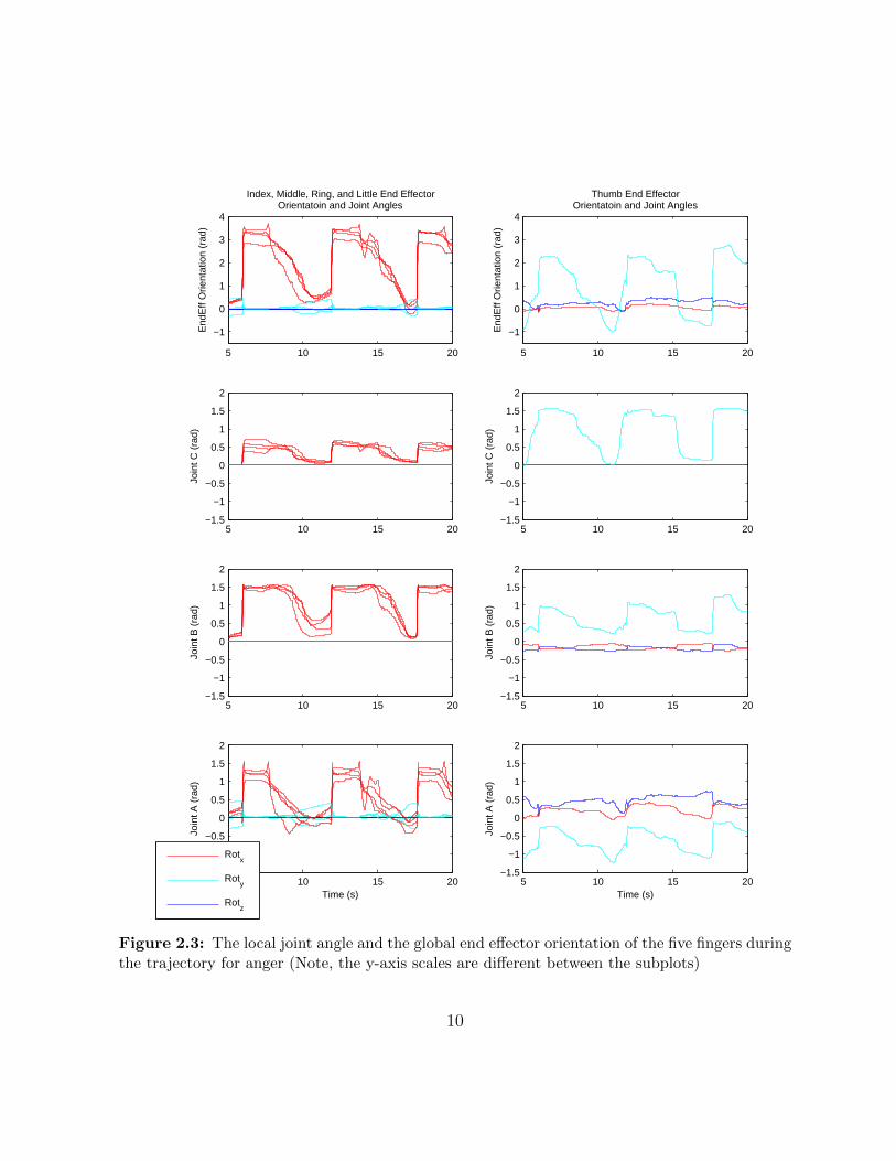
Figures 2.3-2.5 illustrate the time plots of the 45 DOFs recorded by the glove for thethree emotions of anger, joy, and sadness respectively. The plots contain multiple openingand closing motions. As expected, it can be observed that the physically unfeasible DOFssuch as the y and z axes DOFs of the C joints of the non-thumb fingers don’t have anymovement. From the overlaid plots of the non-thumb fingers, it can be observed that thejoints of these fingers perform very similar rotational movements during the trajectories ofall three emotions (i.e., are coupled). The A joints of the non-thumb fingers mainly rotatearound the x-axis and their rotation around the y-axis is minimal. The movements of thejoint angles of the thumb are also illustrated in these figures.
The motion of the thumb is more complicated and involves more DOFs. This can alsobe observed from the plots as both joint B and joint A of the thumb exhibit movement inall three DOFs. However, for all three joints of the thumb, the motion around the y-axisis dominant. In addition, figures 2.3-2.5 illustrate the orientation of the end effectors ofthe fingers in Euler angles with respect to the global frame. The end effector orientationswere obtained through the forward kinematic transformation. The end effector trajectoriessuggest that the end effectors of the non-thumb fingers mainly rotate about the x-axis andthe end effector of the thumb mainly rotates about the y-axis during these affective motions.As can be seen from figure 2.2, for the non-thumb fingers, the bi-directional rotation of theend effector around the x-axis translates to the end effector approaching and retreatingaway from the palm of the hand, i.e. performing flexion and extension. Because the thumbis lowered and positioned in front of the palm, the rotation of the end effector of the thumbaround the y-axis also translates to a similar flexion and extension motion. Therefore, toreproduce the motions contained in this dataset, it is sufficient that the IFLS performsend effector rotations around 1 axis. In other words, the IFLS representing the non-thumbfingers will only need to perform motion in the ZY plane, while the IFLS representing thethumb will only need to perform motion in the ZX plane.
Figures 2.3-2.5 also confirm that the A, B, and C joints of each finger rotate at almostthe same time and with a similar rate i.e. their motion is coupled. This occurs in thetrajectory of all three emotions. The coupled motion of the finger joints is in line withthe literature which suggests that most common motions of the human hand, which are
8

often grasping tasks, involve the coupled motion of the fingers’ joints [20]. In relation tothe rotation of the end effector of the fingers, the coupled motion means that the jointscontribute to the rotation of the end effector all at the same time. This further simplifiesthe motion that the IFLS needs to perform. It suggests that the joints that will contributeto the rotation of the end effector of the IFLS can all be coupled and thus can all beactively controlled by one actuator.
9
5 10 15 20−1.5
−1
−0.5
0
0.5
1
1.5
2
Time (s)
Join
t A (
rad)
Rotx
Roty
Rotz
5 10 15 20−1.5
−1
−0.5
0
0.5
1
1.5
2
Time (s)
Join
t A (
rad)
5 10 15 20−1.5
−1
−0.5
0
0.5
1
1.5
2
Join
t B (
rad)
5 10 15 20−1.5
−1
−0.5
0
0.5
1
1.5
2
Join
t B (
rad)
5 10 15 20−1.5
−1
−0.5
0
0.5
1
1.5
2
Join
t C (
rad)
5 10 15 20−1.5
−1
−0.5
0
0.5
1
1.5
2
Join
t C (
rad)
5 10 15 20
−1
0
1
2
3
4
End
Eff
Orie
ntat
ion
(rad
)Index, Middle, Ring, and Little End Effector
Orientatoin and Joint Angles
5 10 15 20
−1
0
1
2
3
4
End
Eff
Orie
ntat
ion
(rad
)
Thumb End EffectorOrientatoin and Joint Angles
Figure 2.3: The local joint angle and the global end effector orientation of the five fingers duringthe trajectory for anger (Note, the y-axis scales are different between the subplots)
10

5 10 15 20−1.5
−1
−0.5
0
0.5
1
1.5
2
Time (s)
Join
t A (
rad)
Rotx
Roty
Rotz
5 10 15 20−1.5
−1
−0.5
0
0.5
1
1.5
2
Time (s)
Join
t A (
rad)
5 10 15 20−1.5
−1
−0.5
0
0.5
1
1.5
2
Join
t B (
rad)
5 10 15 20−1.5
−1
−0.5
0
0.5
1
1.5
2
Join
t B (
rad)
5 10 15 20−1.5
−1
−0.5
0
0.5
1
1.5
2
Join
t C (
rad)
5 10 15 20−1.5
−1
−0.5
0
0.5
1
1.5
2
Join
t C (
rad)
5 10 15 20
−1
0
1
2
3
4
End
Eff
Orie
ntat
ion
(rad
)Index, Middle, Ring, and Little End Effector
Orientatoin and Joint Angles
5 10 15 20
−1
0
1
2
3
4
End
Eff
Orie
ntat
ion
(rad
)
Thumb End EffectorOrientatoin and Joint Angles
Figure 2.4: The local joint angle and the global end effector orientation of the five fingers duringthe trajectory for joy (Note, the y-axis scales are different between the subplots)
11

5 10 15 20−1.5
−1
−0.5
0
0.5
1
1.5
2
Time (s)
Join
t A (
rad)
Rotx
Roty
Rotz
5 10 15 20−1.5
−1
−0.5
0
0.5
1
1.5
2
Time (s)
Join
t A (
rad)
5 10 15 20−1.5
−1
−0.5
0
0.5
1
1.5
2
Join
t B (
rad)
5 10 15 20−1.5
−1
−0.5
0
0.5
1
1.5
2
Join
t B (
rad)
5 10 15 20−1.5
−1
−0.5
0
0.5
1
1.5
2
Join
t C (
rad)
5 10 15 20−1.5
−1
−0.5
0
0.5
1
1.5
2
Join
t C (
rad)
5 10 15 20
−1
0
1
2
3
4
End
Eff
Orie
ntat
ion
(rad
)Index, Middle, Ring, and Little End Effector
Orientatoin and Joint Angles
5 10 15 20
−1
0
1
2
3
4
End
Eff
Orie
ntat
ion
(rad
)
Thumb End EffectorOrientatoin and Joint Angles
Figure 2.5: The local joint angle and the global end effector orientation of the five fingers duringthe trajectory for sadness (Note, the y-axis scales are different between the subplots)
12
2.2 Design Requirements
Multiple engineering designs are possible for the IFLS. The first step in choosing betweenthese candidate designs is defining a set of requirements as the decision criteria. Therequirements for the design of the IFLS can be classified into three categories. The firstcategory of requirements stems from the target application, as the IFLS will be a componentof an architectural exhibition. The second category relates to the physical and visualinteraction of the sculpture with humans. The third category of requirements is dictated bythe desired kinematic and dynamic motion response of the sculpture. These requirementsapply to the entire electromechanical IFLS system.
The requirements stemming from the architectural application of the IFLS are notabsolute thresholds and are measured qualitatively and relatively between the candidatedesigns. For example, if a particular design meets some criteria but not others, workaroundscan be applied to accommodate a specific design, by modifying other parts of the instal-lation or reducing the functional capabilities. For example, in the case of the Hylozic Soilinstallations presented in figure 1.1, a mechanism called the breathing pore was imple-mented in the installation that used Shape Memory Alloys (SMAs) for actuation. SMAsare highly desirable for the actuation of the breathing pore because they produce smoothmotion without any noise. However, SMAs have low bandwidth and can only produceslow motions. Rather than rejecting SMAs as a result, only slow motion trajectories forthe breathing pore were designed implemented as part of the installation and high velocitymotions were avoided as a compromise to accommodate the low actuator bandwidth whilebenefiting from SMA’s other desirable properties.
At a high level, the electrical part of the system consists of a controller that will controlthe motion of the sculpture, possibly with feedback from sensory mechanisms. For themechanical part of the system, if conventional robotic techniques are to be used, the systemconsists of a rigid skeleton, a actuation mechanism that enables the skeleton to dynamicallymove, and a transmission mechanism that transfers the energy of the actuator to theskeleton. More recent robotic designs can also be considered for the IFLS that combinethe three parts of the conventional designs. In these recent designs, the motion trajectoryof the actuator resembles trajectories intended for the structure and thus the need for aseparate skeleton and the necessary transmission mechanism is eliminated. The electronicpart of the system interacts with the mechanical part through the driving system of theactuation mechanism, which also needs to comply with the requirements of the IFLS.
In this section the three requirement categories are presented. For each requirementcategory, first their importance with respect to the application of this work is discussed.
13

Second, the sub-categories of requirements are introduced and their effect on the electrome-chanical design is analysed. Third, qualitative or quantitative measures are presented forevaluating how well each of the requirements is satisfied.
2.2.1 Application-Specific Requirements (Interactive Architec-ture)
The ultimate goal of the developed system is to enable affective motion generation withinthe domain of interactive architecture. Consequently, there are requirements on the designof the IFLS that stem from the architectural side of the work. As part of an interactivearchitecture exhibition, similar to the tentacles in the Hylozoic Soil series shown in figure1.1, large numbers of IFLS modules are required for an installation. Therefore, cost is animportant factor. The exhibitions are held in various cities and countries and are usuallyprepared for only a few months in advance. Therefore, the production of the IFLS modulesshould not require excessive person-hours. As part of an artistic project, the design of theIFLS should be customizable, i.e., the size, the kinematic structure, the orientation, andthe location of the IFLS modules should be modifiable. In addition, the design should usecomponents that are easily available. Lastly, the maintenance of the IFLS modules shouldbe low cost and require little effort and time.
The architectural constraints discussed in the previous paragraph are: ease of produc-tion, cost of production, customizability, component availability, and maintenance. Withinthese constraints, customizability, component availability, and maintenance are qualitativeconstraints and are best evaluated when the candidate designs are compared against eachother with respect to these constraints. Ease and cost of production are constraints thatcan be quantified. However, instead of determining precise limits on these constraints interms of person-hours or dollars and analyzing each candidate design against them indi-vidually, it is more practical to comparatively analyze these requirements as well.
2.2.2 Human Interaction Requirements
The IFLS mechanism is intended to interact with human observers both physically andvisually. The mechanism creates a visual interaction with the human observers by perform-ing movements that convey emotions. It is important that this affective interaction is notimpacted by artifacts in the movement of the mechanism. As figures 2.3-2.5 illustrate, themotion of the fingers during the affective trajectories is very smooth. However, in roboticsystems, there are common issues in both the control and the mechanical system that can
14
cause undesirable artifacts in the motion of the mechanism. These artifacts often result inrobotic-looking and unnatural motion, and can significantly hinder the ability to conveyaffect via the mechanism’s movement. Thus, the mechanical and the controller design ofthe system must avoid these artifacts as much as possible. In the mechanical design, non-linear responses such as stiction, which causes jerky movements, should be reduced. Inthe design of the controller, aggressive controls that cause artifacts such visible vibrationshould be avoided as much as possible.
The physical interaction with the mechanism occurs when the human observer pur-posely or accidentally touches the sculpture. In both cases, a compliant interaction withthe mechanism is far more desirable than an interaction with a stiff mechanism. A compli-ant mechanism will be considerably safer during the accidental bumps. It will also reducethe mechanical feeling of the interaction, which as discussed can hinder the affective ca-pabilities of the mechanism. Therefore, compliance is a highly desirable feature for theIFLS.
2.2.3 Dynamic Requirements
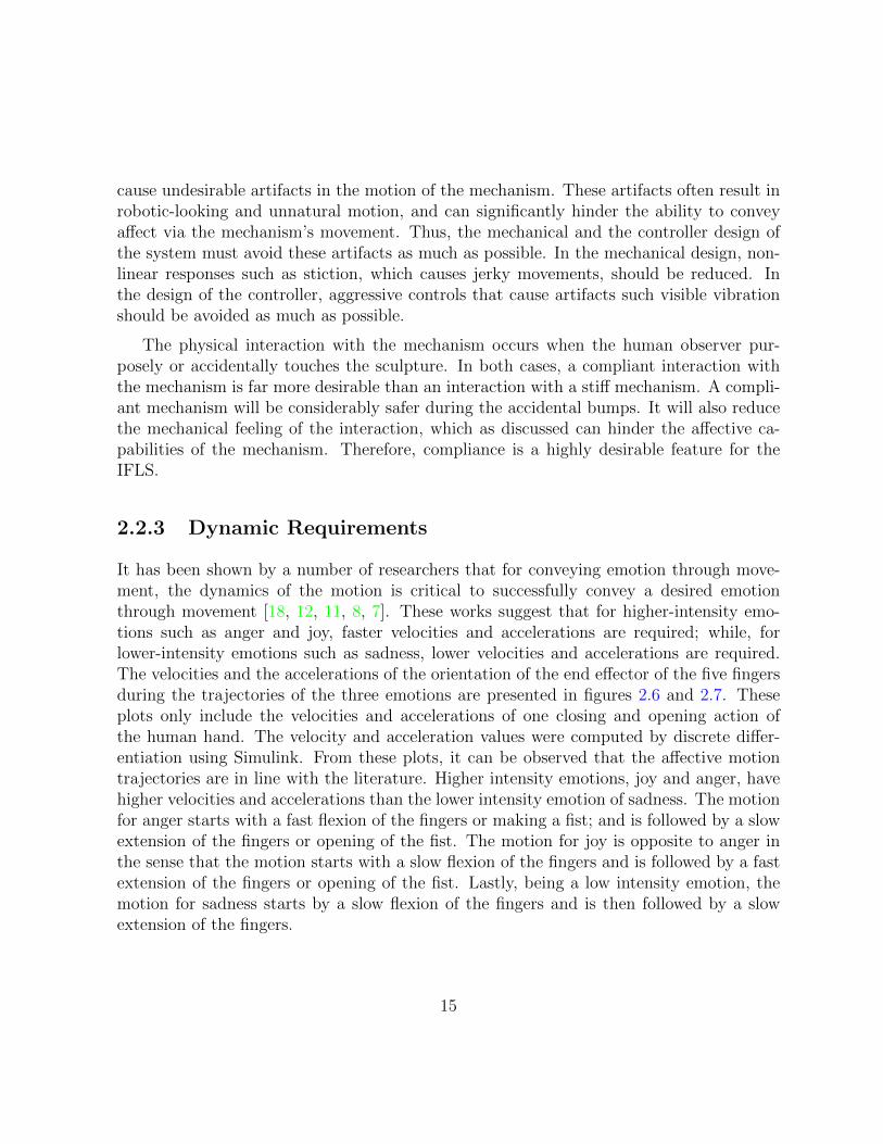
It has been shown by a number of researchers that for conveying emotion through move-ment, the dynamics of the motion is critical to successfully convey a desired emotionthrough movement [18, 12, 11, 8, 7]. These works suggest that for higher-intensity emo-tions such as anger and joy, faster velocities and accelerations are required; while, forlower-intensity emotions such as sadness, lower velocities and accelerations are required.The velocities and the accelerations of the orientation of the end effector of the five fingersduring the trajectories of the three emotions are presented in figures 2.6 and 2.7. Theseplots only include the velocities and accelerations of one closing and opening action ofthe human hand. The velocity and acceleration values were computed by discrete differ-entiation using Simulink. From these plots, it can be observed that the affective motiontrajectories are in line with the literature. Higher intensity emotions, joy and anger, havehigher velocities and accelerations than the lower intensity emotion of sadness. The motionfor anger starts with a fast flexion of the fingers or making a fist; and is followed by a slowextension of the fingers or opening of the fist. The motion for joy is opposite to anger inthe sense that the motion starts with a slow flexion of the fingers and is followed by a fastextension of the fingers or opening of the fist. Lastly, being a low intensity emotion, themotion for sadness starts by a slow flexion of the fingers and is then followed by a slowextension of the fingers.
15

12 14 16
−5
0
5
End
Eff
Vel
ocity
(ra
d/s)
Thumb End Effector Velocity for Anger
Rot
y
14 15 16 17
−5
0
5
Thumb End Effector Velocity for Joy
10 12 14 16
−5
0
5
Thumb End Effector Velocity for Sadness
12 14 16
0
20
40
60
End
Eff
Vel
ocity
(ra
d/s)
Index End Effector Velocity for Anger
Rot
x
14 15 16 17−40
−30
−20
−10
0
10Index End Effector Velocity for Joy
10 12 14 16−5
0
5Index End Effector Velocity for Sadness
12 14 16
0
20
40
60
End
Eff
Vel
ocity
(ra
d/s)
Middle End Effector Velocity for Anger
14 15 16 17−40
−30
−20
−10
0
10Middle End Effector Velocity for Joy
10 12 14 16−5
0
5Middle End Effector Velocity for Sadness
12 14 16
0
20
40
60
End
Eff
Vel
ocity
(ra
d/s)
Ring End Effector Velocity for Anger
14 15 16 17−40
−30
−20
−10
0
10Ring End Effector Velocity for Joy
10 12 14 16−5
0
5Ring End Effector Velocity for Sadness
12 14 16
0
20
40
60
Time (s)
End
Eff
Vel
ocity
(ra
d/s)
Little End Effector Velocity for Anger
14 15 16 17−40
−30
−20
−10
0
10
Time (s)
Little End Effector Velocity for Joy
10 12 14 16−5
0
5
Time (s)
Little End Effector Velocity for Sadness
Figure 2.6: End effector angular velocity of each finger for joy, anger, and sadness (Note, they-axis scales are different between the subplots)
16

12 14 16−400
−200
0
200
400
End
Eff
Acc
eler
atio
n (r
ad/s
^2) Thumb End Effector Acceleration for Anger
Rot
y
14 15 16 17−400
−200
0
200
400Thumb End Effector Acceleration for Joy
10 12 14 16−400
−200
0
200
400Thumb End Effector Acceleration for Sadness
12 14 16−2000
−1000
0
1000
2000
End
Eff
Acc
eler
atio
n (r
ad/s
^2) Index End Effector Acceleration for Anger
Rot
x
14 15 16 17−2000
−1000
0
1000
2000Index End Effector Acceleration for Joy
10 12 14 16−400
−200
0
200
400Index End Effector Acceleration for Sadness
12 14 16−2000
−1000
0
1000
2000
End
Eff
Acc
eler
atio
n (r
ad/s
^2) Middle End Effector Acceleration for Anger
14 15 16 17−2000
−1000
0
1000
2000Middle End Effector Acceleration for Joy
10 12 14 16−400
−200
0
200
400Middle End Effector Acceleration for Sadness
12 14 16−2000
−1000
0
1000
2000
End
Eff
Acc
eler
atio
n (r
ad/s
^2) Ring End Effector Acceleration for Anger
14 15 16 17−2000
−1000
0
1000
2000Ring End Effector Acceleration for Joy
10 12 14 16−400
−200
0
200
400Ring End Effector Acceleration for Sadness
12 14 16−2000
−1000
0
1000
2000
Time (s)
End
Eff
Acc
eler
atio
n (r
ad/s
^2) Little End Effector Acceleration for Anger
14 15 16 17−2000
−1000
0
1000
2000
Time (s)
Little End Effector Acceleration for Joy
10 12 14 16−400
−200
0
200
400
Time (s)
Little End Effector Acceleration for Sadness
Figure 2.7: End effector angular acceleration of each finger for joy, anger, and sadness (Note,the y-axis scales are different between the subplots)
17

Tables 2.1 and 2.2 present the maximum and minimum end effector angular velocitiesand accelerations for all fingers during the three emotions. Note that the data for thethumb is not included in the tables as its velocity and acceleration values are considerablysmaller than those of the other fingers.
Table 2.1: Maximum and minimum end effector angular velocity in rad/s for joy, anger, andsadness
Anger Joy SadnessMax Min Max Min Max Min
Index 23.85 -6.099 7.779 -29.15 4.103 -2.72Middle 30.94 -5.014 7.044 -32.53 5.103 -2.691Ring 37.09 -5.588 5.426 -25.72 3.882 -2.662Little 56.69 -4.941 5.088 -23.6 3.632 -2.353
RANGE 32.84 1.159 2.691 8.926 1.47 0.3676MEDIAN 34.01 -5.301 6.235 -27.43 3.992 -2.676
Table 2.2: Maximum and minimum end effector angular acceleration in rad/s2 for joy, anger,and sadness
Anger Joy SadnessMax Min Max Min Max Min
Index 828.3 -1318 468.3 -686.4 95.4 -95.4Middle 1395 -1016 818.9 -695 175.9 -128.8Ring 1500 -1114 604.6 -517.9 200.7 -200.7Little 1758 -3661 675.2 -484.4 173.5 -179.6
RANGE 929.7 2645 350.6 210.6 105.3 105.3MEDIAN 1448 -1216 639.9 -602.1 174.7 -154.2
It can be observed that, between all three emotions, the fingers achieve their maxi-mum velocity and acceleration values during the motion for anger. In other words, activeflexion motions with the highest velocities and accelerations occur during anger. Withinthe maximums of anger, there is a notable variation between the fingers, with the index
18

finger showing the smallest flexion velocity and acceleration. Thus, in order to ensure theresemblance of the fast flexion motion of at least one of the fingers during anger, the IFLShas to achieve the index finger’s end effector orientation velocity of 23.8rad/s and accel-eration of 828rad/s2. While these values are a lower limit on the maximum requirements,in order to assure a more accurate resemblance of the fast dynamics of anger, values closerto the median of anger’s maximum velocities (34rad/s) and accelerations (1450rad/s2) arepreferable.
Between all three emotions, the minimum velocity values are achieved during the mo-tion for joy and minimum acceleration values are achieved during anger. However, as canbe observed from the plots of anger in figure 2.7, these accelerations correspond to thefingers coming to a sudden stop, at high velocities, by hitting the palm of the hand. Onlyactive responses of the fingers impose requirements on the design of the actuation mech-anism and therefore, minimum acceleration values during anger will not be considered inthe requirements analysis. This means minimum accelerations are also achieved duringthe motion for joy. In other words, active extension motions with the highest velocitiesand accelerations occur during this emotion. Within the minimums of joy, the little fingerachieves the smallest extension velocity and acceleration. Therefore, the IFLS has to atleast achieve the little finger’s end effector orientation velocity of −23.6rad/s and acceler-ation of −484rad/s2. However, again, velocities and accelerations near the median of thiscolumn, which are −27.4rad/s and −602rad/s2, would be preferred. Table 2.3 presents therequired and the desired velocities and accelerations for the IFLS in terms of the flexionand extension motions of the mechanism.
Table 2.3: Required and desired velocity and acceleration of the flexion and extension motionof the IFLS
Velocity (rad/s) Acceleartion (rad/s2)Flexion Extension Flexion Extension
Required 23.85 23.6 828.3 484.4Desired 34.01 27.43 1448 602.1
2.3 Summary of Design Requirements
The requirements on the design of the IFLS are summarized in table 2.4.
19
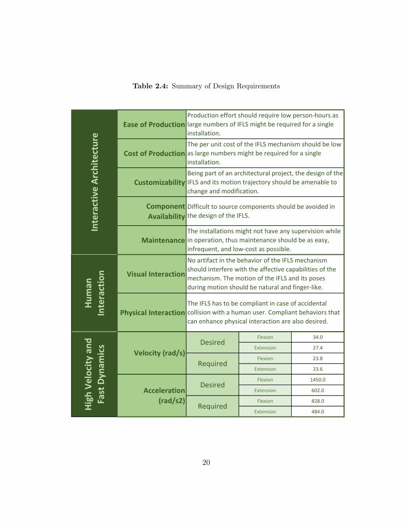
Table 2.4: Summary of Design Requirements
Ease of Production
Cost of Production
Customizability
Component
Availability
Maintenance
Visual Interaction
Physical Interaction
Flexion 34.0
Extension 27.4
Flexion 23.8
Extension 23.6
Flexion 1450.0
Extension 602.0
Flexion 828.0
Extension 484.0
Inte
ract
ive
Arc
hit
ect
ure
Hu
man
Inte
ract
ion
Hig
h V
elo
city
an
d
Fast
Dyn
amic
s Desired
Required
Desired
Required
No artifact in the behavior of the IFLS mechanism
should interfere with the affective capabilities of the
mechanism. The motion of the IFLS and its poses
during motion should be natural and finger-like.
The IFLS has to be compliant in case of accidental
collision with a human user. Compliant behaviors that
can enhance physical interaction are also desired.
The per unit cost of the IFLS mechanism should be low
as large numbers might be required for a single
installation.
Being part of an architectural project, the design of the
IFLS and its motion trajectory should be amenable to
change and modification.
Difficult to source components should be avoided in
the design of the IFLS.
The installations might not have any supervision while
in operation, thus maintenance should be as easy,
infrequent, and low-cost as possible.
Production effort should require low person-hours as
large numbers of IFLS might be required for a single
installation.
Velocity (rad/s)
Acceleration
(rad/s2)
20

Chapter 3
Mechanical System Design
This thesis investigates the construction of a hand-like dynamic structure for affectivemotion reproduction. Numerous designs for robotic hand or hand-like robots exist, whichuse various mechanical and electrical techniques to achieve a number of tasks such asgrasping, gesturing, and exoskeleton assistance [14, 15, 16, 17]. Conventional mechanicaldesigns of robotic hands consist of the following three components: actuator, transmission,and skeleton structure. The actuator provides mechanical energy which the transmissiontransfers to the joints on the skeleton structure. In recent years, a category of pneumaticactuators has emerged that eliminates the need for a separately designed skeleton structure,since the structure is incorporated into the design of the actuation mechanism. The motiontrajectory of these pneumatic mechanisms can be programmed to be very similar to theclosing and opening motions of the fingers.
For the mechanical design of the IFLS, initially, the actuators and transmission designsof the more conventional robotic hands are evaluated against the requirements. The se-lected designs are then compared against the more recent pneumatic actuators in order toselect a suitable design for the IFLS.
3.1 Conventional Mechanical Designs
In conventional robotics, finger-like mechanisms have been developed [14] as small-sizedmanipulators with a series of revolute joints, connected to each other by straight rigidlinks. Since the IFLS’s end effector only needs to rotate around one axis, its roboticsmanipulator design will consist of parallel revolute joints that could be coupled and are
21

linked together by the skeleton of the mechanism. A sample two joint IFLS design isillustrated in figure 3.1. The actuator design in this mechanism provides the mechanicalenergy to rotate these joints. This mechanical energy is transferred from the actuators tothe joints by a transmission mechanism.
J1
J2
τA
L EE
Actuation
Mechanism
EE
L 1
L 2
θ
θ
Figure 3.1: Sample robotic manipulator design for the IFLS
In this section, first the actuator mechanisms used in conventional robotic hands areinvestigated and actuation design candidates are chosen. Each design is evaluated againstthe three categories of requirements and the possibility of using the design for the IFLSis discussed. For the selected candidates, common transmission mechanisms are presentedand are evaluated against the requirements. Based on the evaluations, suitable actuationand transmission pairs for implementation in the IFLS are recommended.
22

3.1.1 Actuators
Four of the main categories of actuators conventionally used for actuating robotic handsare: electromagnetic direct current (DC) motors, pneumatic actuators, hydraulic actuators,and SMA actuators [14, 15]. These actuation solutions are discussed individually in thissection. A brief description of the physical phenomena that enable the output mechanicalenergy of the actuation concept is provided and the different variations of each actuationconcept are analysed. In addition, methods for driving the actuation mechanism andcontrolling its mechanical energy are discussed. Lastly, each solution is evaluated withrespect to the three categories of requirements.
DC Motors
Within all the investigated robotic hand designs [14, 15, 16, 17], DC motors are the mostcommon actuation mechanism. These actuators convert electrical energy to mechanicalpower by opposing magnetic interaction between the stator and the rotor. The two maindesigns for DC motors are brushed and brushless DC (BLDC) motors. Brushed DC motorsare cheaper, more easily available, produce more power and torque, and do not requireexpensive controller circuitry. However, brushed DC motors have low efficiency whichcauses more heat and noise, and also have a shorter life time due to the friction on therotors [21]. BLDC motors provide better efficiency by eliminating rotor friction, achievehigher speed, have smoother torque outputs, and have longer lifetimes. The downsides ofthe BLDC motors are: higher cost, requirement for control circuitry that adds additionalcost, and lower availability and variability in size [21].
The most common method for controlling the output power of both DC motor designsis to use digital pulse width modulated (PWM) electrical signals as the input of the motor.As a high-level overview, PWM signals allow packets of energy into the motor at a specificfrequency. Changing the size of these energy packets, which corresponds to the duty cycleof the signal, results in changing the energy output of the motor. The most importantbenefit of using PWM signals is that they can be produced by commonly available digitalmicrocontrollers. Depending on the impedance of the motor, the duty cycle of the PWMsignal translates to a specific voltage at the input of the motor. The relationship betweenthe duty cycle and the voltage is linear, making the control of the driver system of themotor relatively simple.
DC motors can rotate in both directions, therefore with the proper design of the trans-mission mechanism, they can provide bidirectional motion for the joints. This can consid-erably reduce cost and simplify control, as one actuator can produce active actuation for a
23

joint in both directions. DC motors in general operate at high angular velocities and lowoutput torques. A variety of torque increase mechanisms exist that can bring the torqueand velocity values of DC motors to more suitable ranges. Conventionally, gearboxes havebeen used to achieve torque increase for DC motors. The simple design of gearboxes makesthem cheap and available in a variety of designs and torque increase ratios. Gear backlashor free play is one of the main issues with gearboxes, reducing efficiency and complicatingcontrol [21]. For the affective applications of the IFLS, backlash is particularly disad-vantageous as it is a non-linear behaviour that will result in unnatural motions. Carefuland high-precision designs and performing selective assembly and gear centring can sig-nificantly reduce backlash [21]. However, these actions can also significantly increase costand production time and effort.
The authors in [21] suggest numerous alternative torque increase mechanisms to gear-boxes. One of these solutions is the harmonic drive mechanism, which provide high torqueincrease ratios in compact sizes and do not suffer from backlash. On top of the generalbenefits of harmonic drives, the high speed robotic hand by Namiki et al. [22] providesresults that suggest the high velocity and acceleration requirements on the IFLS can beachieved by DC motors paired with harmonic drives. Namiki et al. [22] use custom builtBLDC motors that allow high current flows into the motor for short periods of time. Thismodification allows for fast velocities and accelerations to be achieved for those short timeperiods, before the motor overheats. In addition, by using harmonic drives they eliminatebacklash, making it possible to perform high gain control that enables the mechanismto achieve considerably higher velocities and accelerations. In their results, Namiki etal. achieve a maximum angular velocity of 300rpm and a maximum torque of, 1.71Nm.300rpm translates to 31.4rad/s in both directions of motion. This angular velocity iswell above the minimum required flexion velocity of 23.8rad/s and extension velocity of23.6rad/s. However, if the torque provided by the actuator is not sufficient to produce therequired angular accelerations, the velocity trajectory of the affective motions cannot befollowed properly and this can interfere with the affective capabilities of the motions.
The possibility of achieving the required acceleration is examined by looking at thetheoretical amount of torque needed from the actuator that will enable the IFLS to achievethe required acceleration. In order to proceed with this analysis, the IFLS is consideredto be a robotic manipulator with n parallel revolute joints. Figure 3.1 illustrates a sampleIFLS design with n = 2 joints. All the joints Ji, i > 1 are considered to be coupled tothe actuation mechanism on J1 with unity torque increase ratios and the assumption thatno energy is lost due to friction. In other words, for any n > 1 the mechanism will beunderactuated. The coupling of the joints means that during the motion of the IFLS, thetorque needed from the actuator is
24

τA = τ1 + τ2 + ...+ τn (3.1)
with τi, i = 1, 2, ..., n being the torque required from the ith joint that enables the endeffector to follow the desired angular acceleration trajectory. The angular acceleration atthe end effector is αEE = α1 + α2 + ...+ αn or the sum of the angular accelerations of thejoints. Because of the unity torque increase ratio, the angular acceleration of all the jointsare equal. Thus,
αi =αEEn
, i = 1, 2, ..., n. (3.2)
The required torque from each joint is:
τi = αiIi, i = 1, 2, ..., n (3.3)
with Ii being the moment of inertia that the ith joint sees. Because of lower mass andshorter length,
Ii < Ii−1, i = 2, 3, ..., n (3.4)
for any joint angle configuration. Substituting equations 3.2 and 3.4 into equation 3.3 willresult in:
τi < τi−1, i = 2, 3, ..., n. (3.5)
Substituting equation 3.5 into equation 3.1 means: τA ≤ nτ1. Substituting τ1 = α1I1 andα1 = αEE
nin the equation results in:
τA ≤ αEEI1. (3.6)
The end effector angular acceleration αEE is at its maximum at the required accelerationvalue αmax = 828rad/s2. The moment of inertia at I1 is at its maximum Imaxwhen themanipulator is at the fully extended length L and the joint angles θi = 0, i = 1, 2, ..., n.In order to get an estimate on Imax, the manipulator is assumed to be a thin rod withuniform mass distribution. This results in Imax = mL2/3 with m being the mass of themanipulator. In this case the maximum required torque is less than or equal to:
25

τmax =mL2αmax
3. (3.7)
We assume the manipulator has a length L = 15cm, which is double the average lengthof a human middle finger, and a cross section of 4cm2. This cross sectional area providesenough space in the links to achieve joint coupling. Assuming the manipulator is a solidcuboid piece of ABS plastic, which is a common thermoplastic used by 3D printers andhas a density of around 1g/cm3, the mass of the rod is estimated to be around 60g. Thus,the required torque at this manipulator mass and length is at most τmax = 0.373Nm.This required torque is considerably less than the torque of 1.71Nm provided by theBLDC motor and harmonic drive pair. Therefore, the approach of Namiki et al. in [22]can achieve the required velocity and acceleration values with BLDC motors paired withharmonic drives.
Note, in equation 3.6, τA = αEEI1 only holds when n = 1 or the manipulator has onlyone joint. However, for the IFLS motion to resemble human-like hand opening and closing,at least two joints are required. This means that the torque needed τA is smaller thanτmax = 0.373Nm. Also, gravity was not considered in these estimate because the angularacceleration due to gravity is significantly smaller than the required angular acceleration.
In practice, energy loss due to friction, non-uniform mass distribution due to the cou-pling mechanism and joint location, and higher required lengths due to the architecturaldesign criteria, can all increase the required torque from the actuation mechanism. How-ever, there are multiple design modifications that can reduce the required amount of torqueor increase the amount of available torque, without compromising the requirements. Therequired torque can be decreased by increasing the number of coupled joints or reducing themass by for example changing the material. Also, Namiki et al. were highly constrained onthe size of their actuation mechanism as they required individual joint actuation, requiringthem to place the actuation mechanism in the links. However, in the design of the IFLS,since the joint motions are coupled, the actuation mechanism is only needed at joint J1.This means that while the size of the actuation mechanism is still confined by architec-tural design constraints, the mechanical constraint on it is more lenient. A larger size forthe actuator corresponds to higher achievable torques if necessary, or cheaper alternativedesigns. Considering the size of the skeleton of the IFLS to be 15cm× 2cm× 2cm, abouttwice the average size of the human hand, an actuator is considered large when it is largerthan this skeleton size and thus cannot be contained inside it.
High prices and low availability are the major issues with harmonic drives and BLDCmotors. Second-hand harmonic drives are priced above 150USD online. With the addi-tional price of around 30USD for BLDC motors [23], this solution costs at least 200USD.
26

Solutions consisting of BLDC motors coupled with conventional gearboxes are priced ataround 70USD at RobotShop.com [24]. Costly and scarce options for BLDC motor designmake brushed motors paired with conventional gearboxes that meet the required torqueand angular velocity values more viable. This actuation pair will reduce efficiency, dura-bility, and most importantly complicates high gain control due to backlash and noisiertorque outputs. For example, the readily available geared DC motor solution provided byPololu online robotic and electronic shop [25] can achieve an angular velocity of 36.7rad/s,can output 0.777Nm of torque, and costs about 25USD. These values are within the re-quirements on the IFLS. However, because of friction, gear backlash and freeplay, andnon-smooth output torque, designing a controller that consistently achieves the maximumrequired torques and velocities in a smooth and natural-looking manner will be a cum-bersome task, when complex motion trajectories, such as the affective motion trajectories,need to be tracked.
DC motor designs do not posses inherent compliance. Works such as [26] achieve activecompliance during grasp actions performed by a robotic hand. However, while activecompliance is beneficial for grasping tasks, for the purposes of this work, where frequentphysical human interaction is a strong possibility, passive compliance is highly desirable.When the actuator driving mechanism is off or the controller is not active, something thatcan happen in an installation very frequently, these designs lose their compliance. They alsoadd the need for an accurate and high-speed force or torque sensor for feedback, makingtheir implementation very costly. Some levels of passive compliance can be achieved ina DC motor-based design by adding elastic and flexible elements to the structure of thesystem. The links of the manipulator can exhibit some levels of flexibility instead of beingrigid, the joints can have elasticity such as the design in [27] for the joints of the iCubrobot, or the structure can be covered with flexible material. These solutions complicatethe design and implementation of the structure of the mechanism. They also reduce theprecision of the trajectory-following controller.
In conclusion, a DC motor-based design can meet the majority of the design require-ments of the IFLS mechanism. Inexpensive and easily available DC motor solutions existthat have the potential of meeting the required velocity and acceleration values. However,nonlinear responses in cheaper DC motor solutions can lead to unnatural and non-smoothmotions. Also, compliance is difficult to achieve. The solutions for achieving compliancecomplicate the design of the trajectory-following controller and increase the productiontime and effort.
27
Pneumatic Actuators
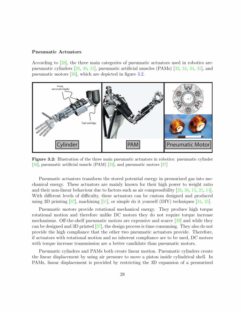
According to [28], the three main categories of pneumatic actuators used in robotics are:pneumatic cylinders [29, 30, 31], pneumatic artificial muscles (PAMs) [32, 33, 34, 35], andpneumatic motors [36], which are depicted in figure 3.2.
Cylinder PAM Pneumatic Motor
Figure 3.2: Illustration of the three main pneumatic actuators in robotics: pneumatic cylinder[30], pneumatic artificial muscle (PAM) [32], and pneumatic motors [37]
Pneumatic actuators transform the stored potential energy in pressurized gas into me-chanical energy. These actuators are mainly known for their high power to weight ratioand their non-linear behaviour due to factors such as air compressibility [28, 38, 15, 21, 14].With different levels of difficulty, these actuators can be custom designed and producedusing 3D printing [37], machining [31], or simple do it yourself (DIY) techniques [34, 35].
Pneumatic motors provide rotational mechanical energy. They produce high torquerotational motion and therefore unlike DC motors they do not require torque increasemechanisms. Off-the-shelf pneumatic motors are expensive and scarce [39] and while theycan be designed and 3D printed [37], the design process is time consuming. They also do notprovide the high compliance that the other two pneumatic actuators provide. Therefore,if actuators with rotational motion and no inherent compliance are to be used, DC motorswith torque increase transmission are a better candidate than pneumatic motors.
Pneumatic cylinders and PAMs both create linear motion. Pneumatic cylinders createthe linear displacement by using air pressure to move a piston inside cylindrical shell. InPAMs, linear displacement is provided by restricting the 3D expansion of a pressurized
28

elastic core into a 1-dimensional linear motion. The operation of PAMs will be furtherdiscussed later in the section. Pneumatic cylinders are capable of providing bi-directionallinear forces. These actuators also behave more linearly than PAMs. Their volume changehas a linear relation with the displacement of the piston. This is unlike PAMs where thevolume change has a highly non-linear relationship with the displacement of the actuator.However, due to their relatively simple design, PAMs are simple to customize and construct.Also, because of their lighter weight, these actuators provide higher power to weight ratiosthan pneumatic cylinders. Because of the elasticity of their core, they provide additionalcompliance on top of the compliance provided by the compressibility of air. Thus, dueto their simple production methods, high customizability, and the fact that they providemore compliance, PAMs will be considered over pneumatic cylinders as a candidate for apneumatic actuation solution.
Because of their simple design, there is a large variety of PAM actuator designs [40]. Oneof the first and still common PAM designs is the McKibben actuator [41]. The McKibbenactuator consists of two main parts, the elastic hollow core and the braided sleeve thatcovers the core. When the elastic core is pressurized and starts to expand inside the braidedsleeve, it forces the sleeve to elongate or shorten along a straight line [42] depending onthe weaving design of the sleeve. The output force and displacement of the PAMs arecontrolled by controlling the internal pressure of the elastic core. PWM signals can beused to drive fast switching valves, such as the MHE2 series valves by Festo, in order tocontrol the internal pressure of the PAM’s membrane [43, 44, 45]. The output pressure ofthe fast switching valve, with respect to the duty cycle of the PWM input signal, is notlinear. This adds to the difficulty of controlling these already highly nonlinear actuators.However, the PWM signalling of fast switching valves provides high bandwidth controlover pressure and the ability to use digital microcontrollers for their control. Fast switchingvalves are relatively cheap as well, with the MHE2 series by Festo being around 100USD.The control of these actuators also requires a pressure source such as an air compressor.PAMs can be produced using simple DIY techniques which for example use cheap siliconehose as the elastic core and cable management braided sleeves. This makes PAMs highlycustomizable as well, with the possibility of different lengths, diameters and even coloursfor architectural purposes. In terms of durability and maintenance, the elastic core canwear out and the sleeves can start to tear. However, because the production process issimple and the costs are low, this is not a major issue.
While the displacement response of the PAM is not linear, its motion is smooth. Thisis mainly due to the damping effects of the compressed air and the elastic membrane.This means that with the appropriate transmission mechanism, this smooth motion canbe transferred to the joints of the IFLS, resulting in smooth and natural motion for the
29

mechanism. As mentioned, PAMs provide inherent compliance as well. Thus, in termsof requirements on the visual and physical interaction with human observers, PAMs canperform well.
Figure 3.3: PAM dynamic response test apparatus. PAM pressurized to 450kPa shown on leftand atmospheric pressure PAM shown on right.
In order to investigate the dynamic capabilities of PAMs, an experimental approachwas taken. The test apparatus shown in figure 3.3 was designed to allow for the testing ofdifferent sizes of PAMs. The PAMs in the apparatus actuated a 1-DOF IFLS mechanism.
30

As discussed in the analysis of the DC Motors, 1-DOF IFLS require the most amount oftorque or, in the case of PAMs, force. The link was a solid piece of wood with the size15cm × 2cm × 2cm, the same as the sample size used in the analysis of DC motors. Therevolute joint was a low friction ball bearing and the force of the PAM was transferredto it by a short tendon and a pulley with a radius of 1cm. Since PAMs only providepulling forces, the pulley on the joint was also coupled with an elastic in order to achievebidirectional movement. The end effector orientation was determined by integrating theangular velocity of the end effector, measured using an ITG 3200 digital gyroscopic sensorby InvenSense. Sample PAMs were produced at various lengths and diameters, usingsilicon hose and cable management braided sleeves. The open-loop pressure response ofthese sample PAMs was studied by inputting different pressure steps to the PAM andmeasuring the orientation at the end effector of the mechanism. Figure 3.4 illustratesthe orientation plot of the end effector of the mechanism in response to a pressure stepwith an amplitude of 450kPa. The sample PAM in this test had a sleeve diameter of2cm, membrane diameter of 1cm and a length of 10cm. Figures 3.5 and 3.6 show theangular velocity and acceleration of the end effector. The maximum velocity reached was35.6374rad/s and the maximum acceleration reached was 1293rad/s2. These figures arewell above the required velocity and acceleration values required for the IFLS. Note thatvarious passive actuation techniques or a secondary PAM for bidirectional active controlof the joint can be used to achieve these dynamic response values for both directions ofmotion. Note, the vibrations observed in the velocity and acceleration plots are due to thefact that the gyroscopic sensor is attached to the tip of the structure using Velcro. Highaccelerations and sudden change of direction of motion causes the sensor to experiencethese vibrations and these are not actual tip vibrations. The magnitudes of the vibrationsare small and cannot not be observed in the orientation plot.
2 2.5 3 3.5 4 4.5
0
1
2
3
4
5
Time (s)
Orie
ntat
ion
$rad
$
Figure 3.4: End effector orientation of PAM-actuated 1 DOF apparatus
31

2 2.5 3 3.5 4 4.5−40
−20
0
20
40
Time (s)
Vel
ocity
rad
/s
Figure 3.5: End effector angular velocity of PAM-actuated 1 DOF apparatus
2 2.5 3 3.5 4 4.5−1500
−1000
−500
0
500
1000
1500
Time (s)
Acc
eler
atio
n ra
d/s^
2
Figure 3.6: End effector angular acceleration of PAM-actuated 1 DOF apparatus
In summary, PAMs are a promising actuator solution for the IFLS. Their productionis simple, they are very customizable and relatively easy to maintain. Their greatestadvantage with respect to the applications of this work is their inherent compliance andsmooth and natural looking motion. They also achieve the dynamic response requirementsof the IFLS. One disadvantage of these actuators is their non-linear response which canmake trajectory-following control difficult. In addition, the cost of the valve for drivingthese actuators is relatively high. However, cheaper pressure control techniques can beinvestigated to replace fast switching valves.
32

Hydraulic Actuators
Hydraulic actuators are the other branch of fluidic actuators. They have many similarcharacteristics to pneumatic actuators, such as high power to weight ratio. The main ad-vantage of hydraulic actuators over pneumatic actuators is their capability of providinghigh force ranges that in applications such as grasping can be very critical [46]. Also dex-terous tasks such as calligraphy are performed by hydraulic actuated hands [47]. Liquidfluids used in hydraulic actuators are far less compressible that gas fluids used in pneu-matic actuators. This reduces the non-linearity of these fluidic actuators in comparisonto pneumatic actuators but also reduces their compliance. In addition, the maintenanceof hydraulic actuators is more difficult and they are usually more expensive. Therefore,because high force ranges are not required in this application, and hydraulic actuators areless compliant, more expensive and harder to maintain, pneumatic actuators are the betterfluidic actuator option for this work.
Shape Memory Alloys (SMA)
SMAs are the actuators that are used in the tentacle mechanism of the Hylozoic Soil shownin figure 1.1. These actuators have also been used in robotic hands [48, 49]. In the operationof SMAs, thermal energy is used to reorient the crystal structure of metal atoms, resultingin a change in material modulus. Electromechanical actuators can be designed to capitalizeon this modulus shift, resulting in a linear displacement at high force when the SMA isheated, often using electrical current. Due to their dependence on temperature change,which is a slow process, SMAs cannot achieve high bandwidth dynamic responses. Theseactuators also have nonlinear response with large hysteresis [50] which complicates theircontrol. SMAs can meet the interactive architecture and human interaction requirements ata satisfactory level, mainly based on the fact that these actuators have been used in variousinteractive architecture installations before. However, due to their slow dynamic responseand difficulty of control they cannot be considered for affective motion applications.
3.1.2 Transmission
The transmission mechanism in conventional robotic mechanism designs transfers the en-ergy of the actuator to the joints of the mechanism. There are various transmission mech-anisms that are used in robotic hand designs [14, 15]. The motion of the IFLS is coupled,meaning that the energy of the actuator located on the first joint has to be transferred toall the joints of the mechanism. Not every transmission mechanism has the capability of
33

providing coupling. As illustrated in figure 3.7, four possible remote transmission mech-anisms that can provide coupling are: Belt and Pulley [51, 52, 53], Gear Series [54, 51],Linkage [55, 56, 57], and Tendon and Sheath [58, 59, 60]. Gear series suffer from backlash,high friction, high weight and design production complications and thus are not consid-ered. Tendon and sheath are also not considered due to high friction and loosening of thetendons that can introduce non-linearities and cause unnatural motion. This leaves Beltand pulley, and linkage designs as the only remaining options. Linkage designs can have asimpler production process and higher customizability by the use of 3D printers. However,linkage designs also require a considerably longer design period. Both methods lose energydue to friction. In addition, in belt and pulley designs, slipping can occur especially whenthe belt starts to loosen up over time and lose grip. This means the maintenance anddurability of belts and pulley designs are also worse. Thus, between the two mechanisms,each one has advantages and disadvantages. Depending the availability of a 3D printer,available design period, and concerns on durability each solution can be viable.
Linkage
Gear Series Belt & Pulley Sheat & Tendon
Figure 3.7: Illustrations of linkage [57], gear series [51], belt and pulley [53], and sheath andtendon [58] transmission mechanisms
34
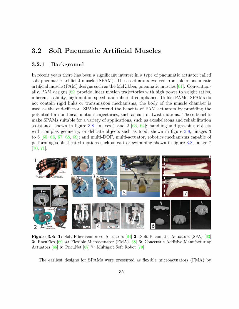
3.2 Soft Pneumatic Artificial Muscles
3.2.1 Background
In recent years there has been a significant interest in a type of pneumatic actuator calledsoft pneumatic artificial muscle (SPAM). These actuators evolved from older pneumaticartificial muscle (PAM) designs such as the McKibben pneumatic muscles [61]. Convention-ally, PAM designs [62] provide linear motion trajectories with high power to weight ratios,inherent stability, high motion speed, and inherent compliance. Unlike PAMs, SPAMs donot contain rigid links or transmission mechanisms, the body of the muscle chamber isused as the end-effector. SPAMs extend the benefits of PAM actuators by providing thepotential for non-linear motion trajectories, such as curl or twist motions. These benefitsmake SPAMs suitable for a variety of applications, such as exoskeletons and rehabilitationassistance, shown in figure 3.8, images 1 and 2 [63, 64]; handling and grasping objectswith complex geometry, or delicate objects such as food, shown in figure 3.8, images 3to 6 [65, 66, 67, 68, 69]; and multi-DOF, multi-actuator, robotics mechanisms capable ofperforming sophisticated motions such as gait or swimming shown in figure 3.8, image 7[70, 71].
1
42
3
5
6
7
Figure 3.8: 1: Soft Fiber-reinforced Actuators [64] 2: Soft Pneumatic Actuators (SPA) [63]3: PneuFlex [69] 4: Flexible Microactuator (FMA) [68] 5: Concentric Additive ManufacturingActuators [66] 6: PneuNet [67] 7: Multigait Soft Robot [70]
The earliest designs for SPAMs were presented as flexible microactuators (FMA) by
35

Suzumori et al. in [72]. In the design of the FMA, 3 separate chambers are present in arubber tube. Pressurizing one or two of the chambers while leaving the rest unpressurised orat lower pressures will cause the rubber tube to exhibit a bending motion. This is becauseof the difference in the elasticity between the outer surface of the pressurized chambers andthe inner core of the rubber tube, with the outer surface being more elastic. Therefore,under pressure, the outer surface extends more than the inner core of the tube, causing thestructure to bend. Fibers are also included in the outer surface of the rubber tube to preventoverstretching the outer surface and bloating. Bloating occurs when the elastic material ofthe SPAM stretches out from the unpressurized shape of the SPAM similar to a balloon(see, e.g., image 2 in figure 3.8). For the interactive architecture application considered inthis work, bloating is highly undesirable. As Samadani et al. [9] suggest, the appearance ofthe mechanism performing the motion also influences the emotion conveyance capabilitiesof the mechanism. Bloating noticeably changes the appearance of the SPAM, which willmake the appearance a factor for affective analysis and may inhibit the communication ofaffect. Furthermore, bloating can degrade the ability of the silicon to fully retract to itsoriginal shape, thus reducing durability.
Since the introduction of the FMA, many SPAM designs have been presented that utilizea similar method for implementing bending motions. In PneuNets [67], the hollow elasticcore of the actuator is partially molded over with a lower-elasticity material, generatingbending motion when pressurized due to the difference in the elasticity of the two materials.In designs such as PneuFlex [69] or soft pneumatic actuator (SPA) [73], the hollow elasticcore of the actuator is partially covered with a much thinner and lighter material suchas a silk mesh that is non-elastic but flexible. This design provides a larger differencebetween the elasticities of the vertical surfaces which results in more bending deformation.In [69], fiber threading around the hollow core is also introduced. While the introductionof the fiber threads might reduce the amount of bending, similar to the fiber in the FMA,it prevents bloating behaviours that are present in [67, 73], which can be undesirable formany applications.
There are several SPAM designs that produce finger-like motion [69, 71, 73]. SPAMdesigns similar to the PneuFlex [69] are the most suitable design for this work. PneuFlexis an actuator designed for grasping applications. Its rest pose and its motion trajectoryboth resemble that of the human finger. In comparison to other finger-like SPAMs, Pneu-Flex maintains its finger-like appearance during its motion, avoiding the distension oftenobserved in SPAM designs (e.g., SPA in figure 3.8, image 2). PneuFlex SPAMs are alsosimpler to construct than the SPAM design from [71] for example, which requires morecomplex elastic hollow core and bend-causing mechanism designs.
36

3.2.2 SPAM Requirement Analysis
In this section, the SPAM actuator is analysed with respect to the three requirementscategories discussed in section 2.2. The requirement analysis of SPAM actuators demandsa slightly different approach than the previous actuation candidates for the IFLS. Becausethese actuators are recent and are mainly still in the research state, there are no off-the-shelf SPAMs available nor are there any well established manufacturing processes forproducing them. A variety of do-it-yourself (DIY) approaches currently exist [69, 71, 73]which all exploit the new advances in 3D printing and silicone rubber technologies. Inthe case of the PneuFlex, for example, 3D printed molds are used to mold elastic siliconecompounds into the desired hollow cuboid shape. Silk mesh and fabric threading are thenused to restrict the motion of the SPAM to the desired trajectory. Driving mechanismsfor SPAMs remain an area of research. Currently, various solutions exist each with theirown advantages and disadvantages. This means that the design of SPAM actuators, theirmanufacturing process, and their driving mechanism are still active research topics withpotential for significant contributions. Current SPAM designs can be modified to rectifyknown issues and make their design more suitable for specific applications such as theIFLS. These opportunities add an attractive dimension to SPAMs that the other actuationsolutions for the IFLS do not posses. However, the early stage of the SPAM technology alsomakes analyzing the IFLS requirements more difficult. Since the PneuFlex actuators arethe most suitable SPAM design for the IFLS, the design and the manufacturing processof these actuators is analysed for the IFLS requirements. The driving mechanism forSPAMs is also an important factor in analyzing how well these actuators meet the IFLSrequirements. Conventional pneumatic driving mechanisms used for actuators such asPAMs and pneumatic cylinders are considered for the analysis of SPAMs.
PneuFlex actuators were designed for grasping applications and no data was avail-able on their performance during fast dynamic motion. Therefore, a pneumatic drivingmechanism was constructed in order to collect the open-loop step response of the Pneu-Flex actuator. Similar to the apparatus designed for conventional PAMs, the orientationchange of the PneuFlex’s tip during the open-loop response is determined by integratingthe tip angular velocity, measured using the ITG 3200 gyroscopic sensor by InvenSense.The sensor communicates with a Teensy 3.1 Microcontroller over the I2C digital interface.
37

PneuFlex
High-speed
3/2 Valve
Pressure
Regulator
Pressure
Source
Exhaust
PSPAMP
reg
Patm
Ps
PPressure
Sensor
Figure 3.9: Pneumatic open-loop circuit
Figure 3.9 illustrates the pneumatic circuit that was designed and implemented to drivethe PneuFlex actuator. The pressure Ps is provided to the circuit using the P15 TC com-pressor by Werther Internationals. This pressure needs to be regulated in order to preventpressure drop when there is air flow in the circuit. The pressure from the compressor isregulated by the NAW2000-N02-2 regulator from SMC. The regulated pressure Preg is fedto a 3/2 high-speed valve. Using a 3/2 valve enables the circuit to be pressurized to Pregand depressurized to atmospheric pressure Patm by a single valve. Festo’s MHE2-MS1H-3/2G-M7-K, capable of switching at 330 Hz, is used as the high-speed 3/2 valve. This valveis considerably more expensive than conventional slower switching valves. However, usingpulse width modulation (PWM) signaling, high-speed valves can provide electronic controlover their output pressure [43, 44, 45]. As discussed in detail in chapter 4, this feature willbe essential in controlling the internal pressure of SPAMs and in turn, controlling the tiporientation. A pressure sensor (MPX5500DP by Freescale) is placed at the pressure intake
38

of the SPAM to measure its internal pressure. Pressure sensor analog measurements areread by a 12-bit ADC on the Teensy 3.1 microcontroller.
In order to improve the dynamic response of the PneuFlex SPAM, its air pressure intakehad to be modified. The air pressure intake of the original PneuFlex is located on the sideof the actuator and the intake tube is considerably narrower than the internal hollow coreof the SPAM and the tubing of the pneumatic circuit. The narrow air intake affects thepressure response of the SPAM by reducing the mass flow rate and dampens its motiondue to the resulting low pass filtering effects. As illustrated in figure 4.1, by bringing theintake of the SPAM to the bottom of the actuator it became possible to increase the intaketube size to 1/4” I.D., which is the tubing size of the pneumatic circuit and is much closerto the width of the SPAM hollow core.
334.41o
65.22o
Figure 3.10: Absolute end effector orientation of the PneuFlex measured on still images
Using this pneumatic circuit and the new PneuFlex configuration, a test is performedon the ITG 3200 gyroscopic sensor to see if the sensor is capable of capturing all the
39

frequencies of motion of the tip of the PneuFlex. First, the sampling rate of the sensor isset to the maximum rate of 800 Hz. Second, a step pressure change which results in thePneuFlex travelling its full range of motion is applied to the actuator. Side-view images aretaken of the PneuFlex at the rest pose and at the fully contracted pose. Third, the angulardisplacement of the tip orientation is measured using Adobe Illustrator from the two poseimages as shown in figure 3.10. Fourth, the angular displacement of the tip is calculated byintegrating the angular velocity measured by the sensor during the step response. Lastly,the two achieved angular displacements are compared to evaluate the validity of the gyro-measured data. The angular displacement from the images, as depicted in figure 3.10,is 334.41◦ − 65.22◦ = 269.19◦ = 4.6983 rads. The angular displacement measured usingthe gyroscopic sensor is 4.6962 rads. This means that the discrepancy between the twomethods is 0.0021 rads, which is small and suggests that the gyroscopic sensor is capableof measuring the angular displacement of the SPAM. Since the Teensy 3.1 microcontrollerwas fully capable of handling the data from the sensor at 800 Hz, no lower sampling rateswere tested. The measured angular velocity was also translated to angular displacementonline, in the Teensy 3.1 microcontroller. The pressure and angular displacement data wastransferred in real-time from the Teensy 3.1 microcontroller to MATLAB Simulink on aWindows machine over USB.
40

0 0.5 1 1.5−10
0
10
20
30
40Flexion Velocity Pro"le
Time (Seconds)
An
gu
lar
Ve
loci
ty (
rad
/s)
−400 −200 0 200 400−120
−100
−80
−60
−40
−20
0
20FFT of Flexion Motion
Frequency (Hz)
Ma
gn
itu
de
(d
B)
0 0.5 1 1.5−40
−30
−20
−10
0
10Extension Velocity Pro"le
Time (Seconds)
An
gu
lar
Ve
loci
ty (
rad
/s)
−400 −200 0 200 400−120
−100
−80
−60
−40
−20
0
20FFT of Extension Motion
Frequency (Hz)
Ma
gn
itu
de
(d
B)
Figure 3.11: Frequency content of the velocity of SPAM’s full flexion and extension step response
The Fourier transform of the step response of the SPAM is also investigated in orderto determine the magnitude of frequencies of motion of the SPAM actuator. Figure 3.11shows the frequency content of the velocity signals during the flexion and extension of theSPAM. The fast Fourier transforms of the two motions show that there is a significantdrop in frequencies above approximately 10 Hz marked by the dashed vertical lines in thefigure. In fact, using the 400 Hz range of measured frequencies, 99.7% of the power ofthe flexion motion is in frequencies under 11 Hz and 99.3% of the power of the extensionmotion is in frequencies under 11 Hz. The exponential decrease in the power of frequenciesabove 11 Hz and the fact that the calculated displacement was inline with the measured
41

displacement, means that it is highly unlikely that the SPAM has any frequency of motionabove 400 Hz, which is the Nyquist frequency of the control system.
Interactive Architecture Requirements
The interactive architecture requirements for the IFLS are explained in section 2.2.1 ofthe requirements chapter. In order to analyze SPAM in this category of requirements,the production method for the PneuFlex SPAM and the presented pneumatic drivingmechanism are individually analysed in each subcategory.
Ease of production: Deimel and Brock describe the production of PneuFlex actuatorsin [69]. In their procedure, a mold is designed and 3D printed for a hollow cuboid core.The negative design of the 3D printed mold leaves marks on the edges of the core thatsimplify the threading of fiber around the elastic core. After threading the fiber aroundthe core, the non-elastic flexible mesh is applied to one of the four vertical faces of thecore. While the design of the 3D printed mold might be time consuming and require trialand error in order to achieve the most suitable dimensions, it only has to be done onceand afterwards, more molds can be printed or the same mold can be used multiple times.The degassing and curing process of the silicone rubber for the elastic core requires a longtime. However, since no human effort is required during the curing process, the curingtime should not cause issues as long as proper time management measures are in place.Threading of fiber around the core can complicate the production of PneuFlex actuatorsif repeatable motion between the produced actuators is a significant concern. The patternand the spacing of the fiber threads dictate the motion trajectory of the actuator. Evenwith the marks on the edges of the elastic core, precisely repeating the thread patternsmight not be easily achievable. However, for IFLS repeatable motion is not a paramountconcern as long as the actuator does perform a finger-like motion. Thus, not a lot of effortand time should be spent on the precise threading of these actuators.
The production of the pneumatic driving circuit is relatively simple. It mainly involvesbuying off-the-shelf components and connecting them together with minimal effort. Thecompressor and the regulator are already sold assembled together. The high-speed valveneeds to be equipped with the correct size fitting for the 1/4” tubing. The pressure and thegyroscopic senors, and the Teensy 3.1 microcontroller require some passive components.At the early stages of production, this requires manual soldering on prototyping boards.However, at higher production volumes, PCB boards can be designed to significantly reducethe soldering effort required.
The most cumbersome task in the production of the PneuFlex actuator and its driving
42

pneumatic circuit is the threading of fabric around its elastic core. In addition, constructingthe electronic circuit for the sensor and the microcontrollers can also be time consumingif no PCBs are designed and ordered for the electronic circuit. The curing period for thesilicone is long (i.e., at least a day), therefore, in order to ensure a properly built siliconecore, with no air bubbles or other defects, extra care must be taken during the castingstages of the silicone.
Cost of production: The cost for the PneuFlex actuator is low, especially if highvolumes are being made and silicone can be bought in high quantities. Experimentally,it was determined that 22.5g of silicone is required for each PneuFlex actuator. Thus,with 7.2kg of silicone available at 200USD [74], more than 300 PneuFlex actuators can beproduced. This results in a per-unit price of less than 1USD. Thus, the most significantportion of the cost is associated with the sensing and the pneumatic driving components.The cost of a PneuFlex actuator that is equipped with both pressure and angular posi-tion sensors and is indvidually controllable, i.e., requires an individual high-speed valve,will be 30USD+70USD+20USD+100USD+10USD = 230USD. These are the costs of thepressure sensor, gyroscopic sensor, Teensy 3.1, Festo’s high-speed valve, and other costssuch as tubing, fitting, and silicone respectively. However, not all of the PneuFlex actu-ators need to be fully equipped in an installation. One advantage of SPAM actuators istheir inherent stability, thus, these actuators do not necessarily need closed-loop controlto achieve trajectory-following. The control signal of a closed-loop trajectory-followingSPAM can be captured and fed to the SPAM in open-loop to achieve similar motion tra-jectories without the use of pressure and gyroscopic sensor. Also, not every SPAM needsto be individually controlled. Thus, multiple SPAMs that perform similar motions canbe driven by a single valve. The cost of the air compressor and electrical power supplyare not considered in these cost estimates, as these components are usually available inengineering and architectural working environments. However, if large numbers of theseactuators are installed, multiple power supplies and air compressors might be requiredwhich considerably increases costs. Thus the per actuator cost of an installation largelydepends on the number of required actuators, how different their motion trajectories willbe, and the importance of disturbance rejection and tracking error performance.
Customizability: As the background section on the SPAM actuators suggests, thedesign of SPAMs and their output motion is highly customizable. The output trajectory ofthe SPAM and its appearance during motion are determined by the design of the castingof the hollow silicone core and the design of the motion-restricting mechanism. With thehelp of 3D printers and other prototyping methods, virtually a limitless variety of siliconecastings can be designed, allowing for various types of motion and static and dynamicposes. In addition, a number of motion restricting methods are available, each resulting in
43
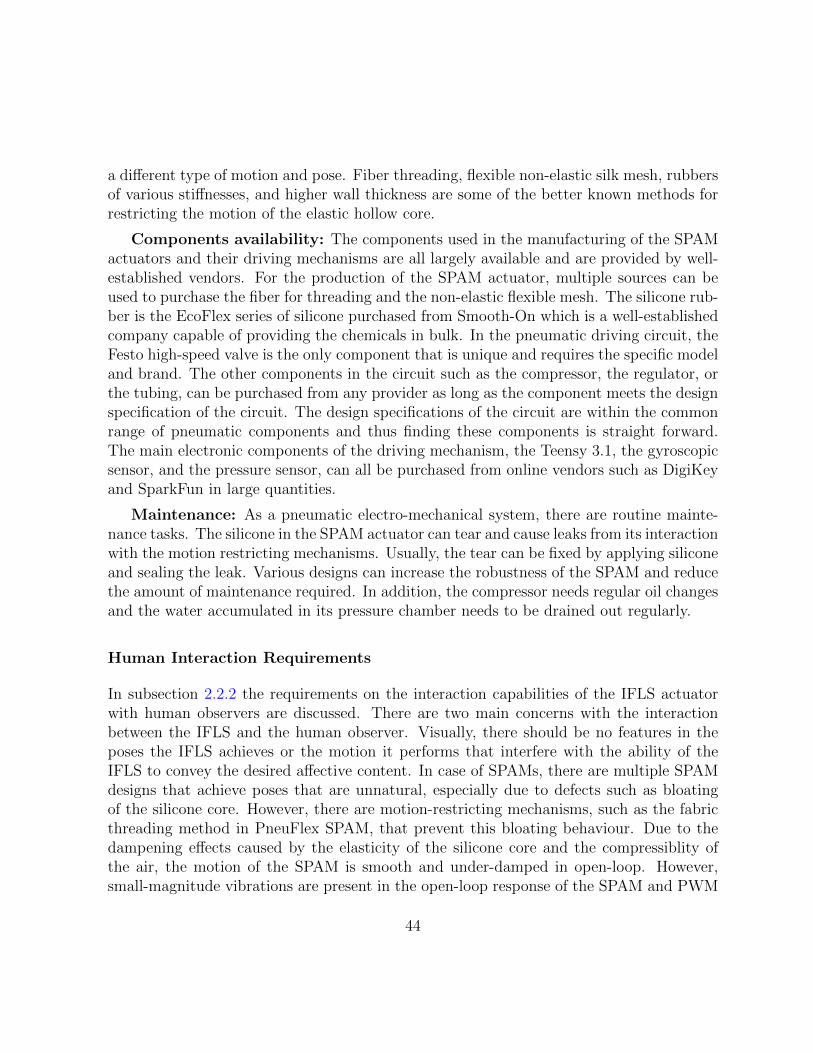
a different type of motion and pose. Fiber threading, flexible non-elastic silk mesh, rubbersof various stiffnesses, and higher wall thickness are some of the better known methods forrestricting the motion of the elastic hollow core.
Components availability: The components used in the manufacturing of the SPAMactuators and their driving mechanisms are all largely available and are provided by well-established vendors. For the production of the SPAM actuator, multiple sources can beused to purchase the fiber for threading and the non-elastic flexible mesh. The silicone rub-ber is the EcoFlex series of silicone purchased from Smooth-On which is a well-establishedcompany capable of providing the chemicals in bulk. In the pneumatic driving circuit, theFesto high-speed valve is the only component that is unique and requires the specific modeland brand. The other components in the circuit such as the compressor, the regulator, orthe tubing, can be purchased from any provider as long as the component meets the designspecification of the circuit. The design specifications of the circuit are within the commonrange of pneumatic components and thus finding these components is straight forward.The main electronic components of the driving mechanism, the Teensy 3.1, the gyroscopicsensor, and the pressure sensor, can all be purchased from online vendors such as DigiKeyand SparkFun in large quantities.
Maintenance: As a pneumatic electro-mechanical system, there are routine mainte-nance tasks. The silicone in the SPAM actuator can tear and cause leaks from its interactionwith the motion restricting mechanisms. Usually, the tear can be fixed by applying siliconeand sealing the leak. Various designs can increase the robustness of the SPAM and reducethe amount of maintenance required. In addition, the compressor needs regular oil changesand the water accumulated in its pressure chamber needs to be drained out regularly.
Human Interaction Requirements
In subsection 2.2.2 the requirements on the interaction capabilities of the IFLS actuatorwith human observers are discussed. There are two main concerns with the interactionbetween the IFLS and the human observer. Visually, there should be no features in theposes the IFLS achieves or the motion it performs that interfere with the ability of theIFLS to convey the desired affective content. In case of SPAMs, there are multiple SPAMdesigns that achieve poses that are unnatural, especially due to defects such as bloatingof the silicone core. However, there are motion-restricting mechanisms, such as the fabricthreading method in PneuFlex SPAM, that prevent this bloating behaviour. Due to thedampening effects caused by the elasticity of the silicone core and the compressiblity ofthe air, the motion of the SPAM is smooth and under-damped in open-loop. However,small-magnitude vibrations are present in the open-loop response of the SPAM and PWM
44

control method for achieving variable internal pressures can cause additional vibration inthe motion. Therefore, the performance of the controller is also critical in keeping themotion of the SPAM smooth.
A strength of SPAM designs is their physical characteristics during physical interactionbetween the IFLS and the human observers. Due to their inherent compliance and lackof rigid links, SPAMs are very safe during contact and physical interaction with humanobservers. They can possibly encourage human interaction due to the soft and naturalfeeling of the silicone both during motion and at rest.
Dynamic Requirements
In order to analyze the velocity and acceleration requirements discussed in subsection2.2.3, step pressure changes were applied to the SPAM until the required velocities andaccelerations were met by the SPAM. The angular velocity of the tip of the PneuFlex wasmeasured from the gyroscopic sensor and its angular acceleration was calculated onlinein Simulink. The open-loop step response trials were initiated with a regulator pressureof Preg = 150kPa. Preg was increased in 50kPa increments until the required angularvelocities and accelerations were reached during the flexion and extension response of theSPAM. As the internal pressure response of the SPAM depicted at the bottom of figure 3.12suggests, at a regulator pressure of 250kPa, maximum and minimum dynamic requirementswere achieved.
45

2 2.5 3 3.5 4−10
0
10
20
30
40
Vel
ocity
(ra
d/s)
7 7.5 8 8.5 9−40
−30
−20
−10
0
10
Vel
ocity
(ra
d/s)
2 2.5 3 3.5 4−1500
−1000
−500
0
500
1000
1500
Acc
eler
atio
n (r
ad/s
2 )
7 7.5 8 8.5 9−1500
−1000
−500
0
500
1000
1500A
ccel
erat
ion
(rad
/s2 )
Figure 3.12: SPAM’s full flexion and extension tip orientation response
Note the under-damped response of the internal pressure of the SPAM with respect to250kPa step pressure at the valve. This under damped pressurization is due to the lowpass filter behavior of the SPAM in the pneumatic circuit.
Table 3.1 presents the maximum and minimum achieved angular velocities and accel-erations by the PneuFlex’s end effector. It can be seen that in fact all the desired angularvelocities and accelerations for the end effector of the IFLS presented in table 2.3 areachieved.
46

Table 3.1: End effector orientation, velocity, and acceleration of PneuFlex SPAM design
Max MinOrientation(rad) 4.696 0Velocity(rad/s) 34.84 -37.23Acceleration(rad/s2) 1222 -1384Pressure(kPa) 251.2 102.7
3.3 Mechanical System Design Summary
In summary, because the SPAM actuator was capable of achieving the human interactionand fast dynamic requirements of the IFLS, it is chosen as the design for the IFLS mech-anism. In some categories of interactive architecture requirements, SPAMs do not ratewell. Depending on the design of the installation, deploying SPAMs can get costly. Theirproduction can also get cumbersome and time consuming depending on the requirementsfor repeatablity. However, they are very customizable and they do not require an exter-nal skeleton or a transmission mechanism. In addition to meeting the requirements inmost categories, SPAM research is still in the early stages, with a significant potential forinnovation and further discovery.
As the three most suitable actuation designs for the IFLS, the performance of the SPAMactuator, DC motors, and PAMs against the IFLS requirements is compared in table 3.2.
47

Table 3.2: Comparison of the three most suitable actuation options against the requirementsfor the IFLS mechanism
DC Motor PAM SPAM
Ease of
Production
Skeleton design and
attachment of actuation to
skeleton is difficult
Skeleton design and
attachment of actuation to
skeleton is difficult
With no skeleton
requirements, the
production effort is low
Cost of
Production
Higher if BLDC designs are
chosen but medium with
brushed motors are used
Costly if control using high-
speed valve is used for every
individual actuator
Costly if control using high-
speed valve is used for every
individual actuator
Customizability
Not much customization is
possible except through
transmission mechanism
and the skeleton
Variety in size and color is
possible, however, full
customization of the
mechanism is hindered by
the transfer mechanism and
the skeleton
Highly customizable both in
static pose and looks, and in
the motion trajectory
Components
Availability
DC motors and their
required components are
largely available through
online vendors with multiple
alternatives
Most components are
available online with
multiple alternatives. Only
few options are available for
High-speed valve
Most components are
available online with
multiple alternatives. Only
few options are available for
High-speed valve
MaintenanceLow maintenance as DC
motors designs are robust
The compressor requires
monitoring for oil levels,
leaks are possible but easy
to fix
The compressor requires
monitoring for oil levels,
leaks are possible but easy
to fix
Visual Interaction Achievable through
expensive designs with
minimal non-linearities
With simple low-friction
transmission mechanism
and skeleton, smooth and
natural motion is possible
Natural and smooth motion
is inherently available
Physical
Interaction
Achievable with complex
and costly designs without
any passive compliance
While the actuator provides
compliance, the rigid
structure will limit the
compliance
Highly compliant and "soft"
even when not actuated
Velocity (rad/s)
Possible with either large
size and heavy motors or
high-cost small motors (up
to 10x smaller in volume or
weight)
The desired velocities were
experimentally achieved
The desired velocities were
experimentally achieved
Acceleration
(rad/s2)
Possible with either large
size and heavy motors or
high-cost small motors (up
to 10x smaller in volume or
weight)
The desired velocities were
experimentally achieved
The desired velocities were
experimentally achieved
48

Chapter 4
SPAM Control1
In applications of SPAMs such as grasping [69], low speed gait [70], and rehabilitationassistance [63], open-loop feedforward controllers are used to control the SPAMs. Theseapplications are mainly exploiting the compliance properties of SPAMs to conform to thebody or grasped object and provide appropriate force, at relatively slow velocities andaccelerations. To the best of the author’s knowledge, no work on SPAMs focuses oncontrolling the fast dynamic response of these actuators to generate high velocity andacceleration motions. In particular, no work to date achieves closed-loop control over thehigh speed response of these actuators.
Due to the similar design of SPAMs and conventional PAMs, closed-loop controllerdesigns for conventional PAMs are investigated as a starting point for designing a closed-loop controller for SPAM actuators. Modeling PAMs is a difficult task because of the non-linear relationship between the change in the pressure of the elastic core and the changein the actuator’s geometry and volume [75]. The non-linear response of these actuatorscomplicates their position or force control. Joupilla and Ellman [45] and Minh et al.[76]use linear PID pressure and position controllers in cascade mode and achieve acceptableposition tracking results. In their design, the inner loop of the cascade controller usespressure feedback to control the pressure at the intake of the actuator. The outer loop usesthe reference position trajectory and position feedback to provide the reference trajectoryof the inner loop pressure controller. The idea of cascade controller with feedback for bothpressure and position is investigated in order to design a cascade PID controller for theSPAM actuator.
In section 3.2.2, an electromechanical system with pneumatic and electronic circuitry
1An early version of this chapter has been submitted to IROS 2015
49

was designed that enables the PneuFlex SPAM to achieve fast dynamic responses in open-loop. The system also provides feedback on both the tip orientation and the internalpressure of the SPAM. In order to achieve closed-loop control, the pneumatic circuit ismodified to improve the noise levels of the variable pressure driving mechanism. A linearPID pressure and position controller in cascade mode, similar to controllers for conventionalPAMs [45, 76], is designed and implemented in the system to control the position outputof the SPAM.
In this chapter, first, an approach for controlling the PneuFlex actuators is proposed.The slight modifications to the design of the PneuFlex are explained, the elctromechanicalsystem for providing electronic control over the actuator is presented, and the closed-loop controller is discussed. Second, the proposed approach is implemented and verifiedexperimentally.
4.1 Proposed Approach
4.1.1 PneuFlex Actuator design modification
During the early stages of experimentation, it was observed that the PneuFlex actuatorsshow signs of damage at the points where the fabric threads meet the edges of the SPAM.This issue was amplified when the PneuFlex actuator was driven at higher velocities. Leaksstarted to occur after only a few high-speed trials and lots of effort and time had be putin to fix the leaks. In order to improve durability and prevent this damage, and also torelocate the air pressure intake to the bottom of the actuator, modified PneuFlex actuatorswere designed. Wide ribbons, which do not cut through the silicon as easily, were used asa replacement for the original thin fibers. The resulting custom built SPAM structure andits curved motion trajectory is shown in figure 4.2. From this point on, SPAM will referto this custom built actuator based on the PneuFlex.
50

Nonelastic Element
1/4” Air Intake
Gyro/Accelerometer
Wide Ribbon Threading
Hollow Core
Figure 4.1: Components of the modified SPAM-based on the PneuFlex actuator
Ref. Frame
End E!.
Frame
Figure 4.2: The motion frames of the custom built SPAM with curved motion trajectory (Note,still frames taken from video)
4.1.2 Electromechanical Driving Mechanism
In this section, the pneumatic and the electromechanical systems that enable the actua-tion of the SPAM are discussed, starting with a brief theoretical analysis of the SPAMactuator. In order to model SPAMs, similar to conventional PAMs [75], conservation of
51

energy can be used to determine the relationship between the internal pressure P , actuatorvolume V , torque τ , and angular position θ. The law of conservation of energy states that,dWout = dWin where for SPAMs the output work is dWout = −τdθ and the input work isdWin = (P − Patm)dV . Combining these equations results in:
− τdθ = (P − Patm)dV. (4.1)
Equation (4.1) suggests that the output torque and angular displacements of the SPAMare determined by its internal pressure and its changing geometry during motion. Sincethis geometry change is pre-determined by the physical design, internal pressure is theonly parameter available for controlling the force and position output of the SPAM. In thisthesis, only the position output of the SPAM is a concern.
Pulse Width Modulation (PWM) of high-speed valves ([43, 44, 45]) is used to controlthe internal pressure of the SPAM actuator. The main benefits of PWM with high-speedvalves are low size and cost, quick response time or low latency, low hysteresis, and relativelylinear operating regions [44]. In the PWM approach, the duty cycle of the high-speed valvedetermines the output pressure of the valve. Thus, this duty cycle is the control signal ofthe feedback closed-loop controller.
Figure 4.3 depicts the pneumatic circuit of the system which is similar to the open-loopexperimentation circuit depicted in figure 3.9. Many of the components of the closed-loop driving circuit are the same as the components in the open-loop circuit. The high-speed 3/2 valve used is Festo’s MHE2-MS1H-3/2G-M7-K, capable of switching at 330 Hz.Pressure is provided to the valve by a pressure source (P15 TC by Werther Internationals)and pressure regulator (NAW2000-N02-2 by SMC) pair. The electronic circuit of theclosed-loop system is also similar to the circuit for the open-loop system. The pressuresensor (MPX5500DP by Freescale) provides analog electronic feedback on the internalpressure of the SPAM. The analog signal is read by the 12-bit ADC of a Teensy 3.1microcontroller. The orientation of the SPAM is measured using the ITG3200 gyroscopicsensor by InvenSense which interfaces with the Teensy 3.1 microcontroller over I2C. In theclosed-loop control system, the controller is implemented on the Teensy 3.1 and the PWMcontrol signal for the valve is provided by one of Teensy’s 16-bit PWM outputs. The PWMsignal is fed to a switching mode MOSFET that drives the high-speed valve at its ratedvoltage of 24V.
One of the main disadvantages of using high-speed valves for pressure control is thatthe output pressure is not smooth. The output pressure of the valve is produced by thevalve pushing in or letting out high pressure packets of air at the rate of switching. This
52

discrete application and exclusion of air, while providing variable mean pressure at differentswitching duty cycles, results in a high magnitude of noise at the output pressure of thevalve. This noise makes the readings from the pressure and the gyroscope sensors noisyas well, which will complicate the feedback control task using these readings. In orderto reduce the magnitude of noise in the system, a pneumatic Low Pass Filter (LPF) isdesigned and implemented. Figure 4.4 shows a picture of the pneumatic LPF. It consistsof two main pneumatic components: the pressure tank and the pneumatic resistance. Thepressure tank is a syringe and the pneumatic resistance is provided by inserting a porousplug into the output tube of the LPF (here, we used a pipe cleaner). This low cost noisefiltering solution provides the ability to fine tune the low pass filter in a simple and quickmanner by changing the volume of the syringe or the length of the porous plug. By tuningthese two parameters, at 3mL syringe volume and 2.5cm porous plug length, the magnitudeof oscillation on pressure caused by PWM was reduced to less than ±5% at 50% duty cycle.
53

Pull down
Pneu. Resistance
SPAM
LPF Pneu.
Resistance
LPF Tank
High-speed
3/2 Festo Valve
Pressure
Regulator
High Pressure
Source
Exhaust
P
Pressure
Sensor
PSPAM
Pvalve
PReg
Patm
PS
Figure 4.3: The pneumatic circuit for the control of the SPAM actuator
PIn
Filtered POut
Porous plug
Pressure Tank
Figure 4.4: Pneumatic low pass filter
54
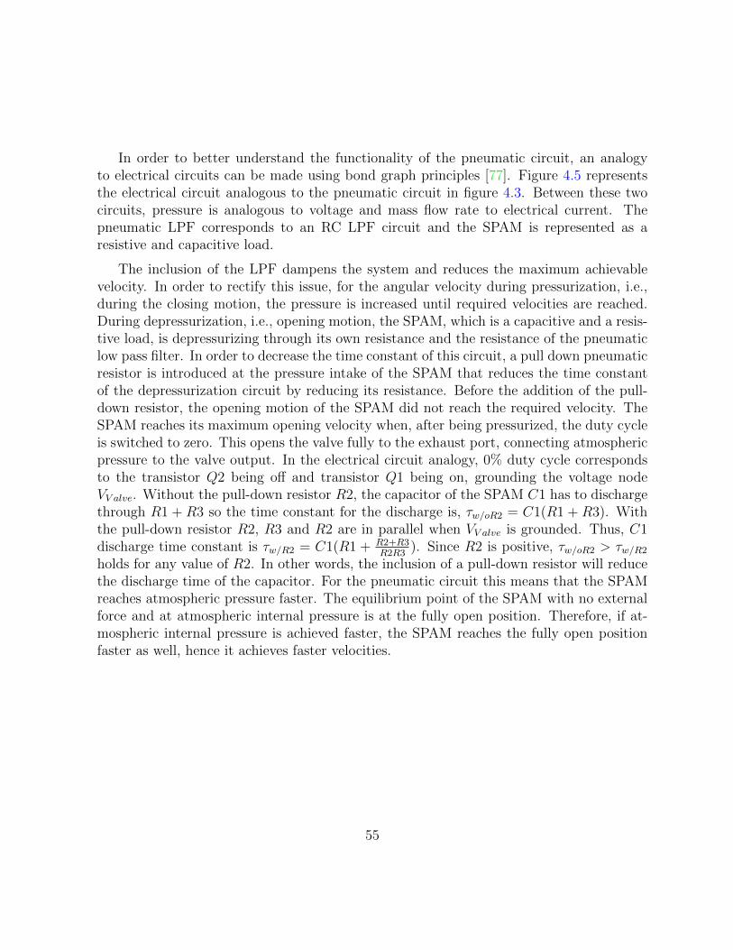
In order to better understand the functionality of the pneumatic circuit, an analogyto electrical circuits can be made using bond graph principles [77]. Figure 4.5 representsthe electrical circuit analogous to the pneumatic circuit in figure 4.3. Between these twocircuits, pressure is analogous to voltage and mass flow rate to electrical current. Thepneumatic LPF corresponds to an RC LPF circuit and the SPAM is represented as aresistive and capacitive load.
The inclusion of the LPF dampens the system and reduces the maximum achievablevelocity. In order to rectify this issue, for the angular velocity during pressurization, i.e.,during the closing motion, the pressure is increased until required velocities are reached.During depressurization, i.e., opening motion, the SPAM, which is a capacitive and a resis-tive load, is depressurizing through its own resistance and the resistance of the pneumaticlow pass filter. In order to decrease the time constant of this circuit, a pull down pneumaticresistor is introduced at the pressure intake of the SPAM that reduces the time constantof the depressurization circuit by reducing its resistance. Before the addition of the pull-down resistor, the opening motion of the SPAM did not reach the required velocity. TheSPAM reaches its maximum opening velocity when, after being pressurized, the duty cycleis switched to zero. This opens the valve fully to the exhaust port, connecting atmosphericpressure to the valve output. In the electrical circuit analogy, 0% duty cycle correspondsto the transistor Q2 being off and transistor Q1 being on, grounding the voltage nodeVV alve. Without the pull-down resistor R2, the capacitor of the SPAM C1 has to dischargethrough R1 + R3 so the time constant for the discharge is, τw/oR2 = C1(R1 + R3). Withthe pull-down resistor R2, R3 and R2 are in parallel when VV alve is grounded. Thus, C1discharge time constant is τw/R2 = C1(R1 + R2+R3
R2R3). Since R2 is positive, τw/oR2 > τw/R2
holds for any value of R2. In other words, the inclusion of a pull-down resistor will reducethe discharge time of the capacitor. For the pneumatic circuit this means that the SPAMreaches atmospheric pressure faster. The equilibrium point of the SPAM with no externalforce and at atmospheric internal pressure is at the fully open position. Therefore, if at-mospheric internal pressure is achieved faster, the SPAM reaches the fully open positionfaster as well, hence it achieves faster velocities.
55

VSPAM
VValve
Figure 4.5: Electrical circuit analogy of the pneumatic circuit with low pass filter and voltagedivider
This low cost and easily tunable pneumatic resistor and low pass filter enable the PWMsignalling of fast response pneumatic valves in order to control the out pressure of thecircuit. These components reduce noise to levels suitable for feedback closed-loop control.The reduction is achieved without compromising the benefits of using PWM singaling offast valves, which are: low latency, low hysteresis, and near linear operation region. TheSPAM is also capable of achieving fast dynamics with the inclusion of these pneumaticcomponents.
4.1.3 Controller
Considering the plant of the SPAM actuation system including the pneumatic circuit, thesystem can be divided into two sub-plants, as depicted in figure 4.6. The first sub-plantrepresents the pneumatic circuit of the system and is mainly governed by the switchingresponse of the valve, the LPF and the pull-down resistor, and the SPAM as a pneumaticload. The input to the plant is the duty cycle of the valve and the output is the pressureat the intake of the SPAM. The second sub-plant of the system is the mechanical structureof the SPAM actuator and its end effector orientation response with respect to its internalpressure. The input of the plant is the pressure at the intake of the SPAM and the outputof the plant is the end effector orientation. Feedback is provided for the output of both ofthese sub-plants using the pressure and gyroscope sensors. The sub-plants are connectedin series and there is no direct control over the input of sub-plant 2, i.e., the pressure at theintake of the SPAM can only be controlled by the pneumatic circuitry. Thus the controllerhas to be capable of controlling the end effector orientation of the SPAM using the valveduty cycle as its control signal.
The controller depicted in figure 4.6 is similar to cascade controllers previously used forPAMs [76, 45]. However, instead of using the outer loop position controller to provide areference for the inner loop pressure controller, the pressure reference trajectory is obtained
56

by assuming a linear relationship between the internal pressure change of the SPAM andits end effector orientation. The relationship is obtained from the open-loop analysis of thepressure step response of the SPAM actuator. At an internal pressure of 250kPa the SPAMreaches around 3.97 rad steady-state orientation. Using these values, the relationshipbetween pressure and orientation at 101kPa atmospheric pressure is, p = 250−101
3.97θref + 101.
This relationship is used to calculate the required pressure reference signal from the endeffector orientation reference signal. Both controllers have duty cycle signals as their outputwhich are summed in order to determine the final control signal. The duty cycle signalhas 12-bits of resolution and the frequency of the PWM signal is 300 Hz. With respect tothis duty cycle resolution, the PID gains of the position controller are, Kp = 200, Ki = 10,Kd = 20000. The gain for the pressure controller was 1.63. The controller is tuned so thatthe control signal is mainly determined by the pressure feedback controller and the positioncontroller will only fine tune the resulting motion of the SPAM actuator towards the desiredposition trajectories. A Teensy 3.1 microcontroller was used for the implementation of thiscontroller. The controller loop was set at 800 Hz.
By taking advantage of the modifications and solutions discussed in the previous sec-tions, such as reducing the PWM signaling noise of the fast pneumatic valve, it is shownthat a linear cascade controller is capable of controlling the non-linear SPAM actuator.The performance of this controller is presented in the following section.
PressureDuty Cycle
Pressure Gain Controller
Valve, Pneumatic Circuit &CSPAM Pressure Plant
CSPAM Pressure to Orientation Plant
1End EffectorOrientation
1ReferenceOrientation
Orientation PID Controller
Orientaion to PressureLinear Model
Figure 4.6: Pressure-orientation closed-loop controller system for SPAM actuators
4.2 Experiments
4.2.1 Reference Signal
The parallel controller depicted in figure 4.6 requires orientation reference trajectories.The goal of the controller is to drive the SPAM actuator to emulate, as closely as possible,
57

the opening and closing of a single finger during affective hand movement. The fingertip orientation data from the dataset [9] of affective hand opening and closing movementsdescribed in section 2.1 was used to generate the reference trajectories. More specifically,the finger tip orientation trajectories of the middle finger for the three emotions of joy,anger, and sadness were chosen as the reference signal for the controller. In the datasetfrom [9], the joint angle data was collected using a data glove at 84 samples/second. Thecalculated fingertip orientation from this dataset was interpolated to 800 Hz to match thecontrol system frequency, and low pass filtered at a cut off frequency of around 84 Hz,which is well above the Nyquist frequency of the sampled data. The low-pass filteringresulted in a smoother response from the controller.
4.2.2 Control System Requirements
The two categories of requirements discussed in 2.2 that apply to the controller performanceare the human interaction and velocity and fast dynamic response categories. Achievingthe required velocities and accelerations are an important requirement for the controllerand the SPAM actuators. Analysis of the SPAM actuators during the design of the systemhas shown that the required peak velocities and accelerations are achievable in open-loop.Closed-loop control is required to ensure that both the peak velocities and accelerationsand the expressive modulations of the velocity during movement are accurately reproduced.Tracking error during the entire trajectory in orientation, velocity, and acceleration are alsoimportant if the SPAM movement is to resemble the closing and opening motion of thefinger.
Human interaction requirements should also be met by the controller design. Visually,the controller should not introduce artifacts that divert the observer’s attention away fromthe main goal of emotion conveyance. Therefore, behaviours such as visible vibrations arehighly undesirable. Physically, the inherent compliance of the SPAM actuator should notbe diminished due to aggressive control.
4.2.3 Controller Results
Figures 4.7, 4.8, and 4.9 show the end effector orientation, the respective reference, andthe tracking error of the joy, anger, and sadness motion trajectories respectively. Themotion for joy starts by closing the finger with medium velocities and accelerations. Afterperforming subtle back and forth motion near the closing pose, the finger opens with highvelocity and acceleration. The trajectory for anger starts with rapid closing motion of
58

the fingers. After a period of no motion, the fingers are opened at medium velocities andaccelerations. The trajectory for sad starts with a slow closing motion of the fingers and isfollowed by their slow opening motion. Since a short delay in the response of the controllerdoes not impede emotion conveyance, the response of the system has been slightly time-shifted to align it with the reference signal for all three trajectories.
In order to determine whether the tracking error performance of the system is accept-able for each target emotion, the variation between the end effector trajectories of thenon-thumb fingers in the human demonstrations, as illustrated in figures 2.3 to 2.5, areconsidered. The maximum variation between the trajectories of the non-thumb fingers inthe human demonstrations are 0.87rads for anger, 0.34rads for joy, and 0.27rads for sad-ness. Table 4.1 presents the maximum magnitude and the mean of the orientation trackingerror achieved by the IFLS and the proposed controller. The mean error is smaller than thetrajectory variation observed in the human demonstrations for all three emotions. Fromthe plots in figures 4.8 and 4.9, it can be observed that the tracking error is below the vari-ation values during the entire trajectory for anger and sadness. The maximum trackingerror within all three trajectories occurs during the closing motion of the joy trajectory,shown in figure 4.7. The plot of the tracking error for joy illustrates that, except duringthe opening motion of the SPAM, the tracking error is smaller than the variation observedin the human demonstrations of joy. In particular, the tracking error is low when subtlemovements are performed near the closed pose, where the velocities are lower and trackingerror will be more noticeable.
59

10.5 11 11.5 12 12.5 13 13.5 14 14.5 15−0.5
0
0.5
1
1.5
2
2.5
3
3.5
4
Orie
ntat
ion
(rad
)
a. Reference and Experimental End Effector Orientation for the Joy Motion
Expe.Ref.
10.5 11 11.5 12 12.5 13 13.5 14 14.5 15−0.5
0
0.5
1
Time (s)
Orie
ntat
ion
Err
or (
rad)
b. Orientation Tracking Error
Error
Figure 4.7: a. Reference and experimental end effector orientation for the joy motion b.Orientation tracking error
60

9 10 11 12 13 14 15 16−0.5
0
0.5
1
1.5
2
2.5
3
3.5
4
Orie
ntat
ion
(rad
)
a. Reference and Experimental End Effector Orientation for the Anger Motion
Expe.Ref.
9 10 11 12 13 14 15 16−0.5
0
0.5
1
Time (s)
Orie
ntat
ion
Err
or (
rad)
b. Orientation Tracking Error
Error
Figure 4.8: a. Reference and experimental end effector orientation for the anger motion b.Orientation tracking error
61
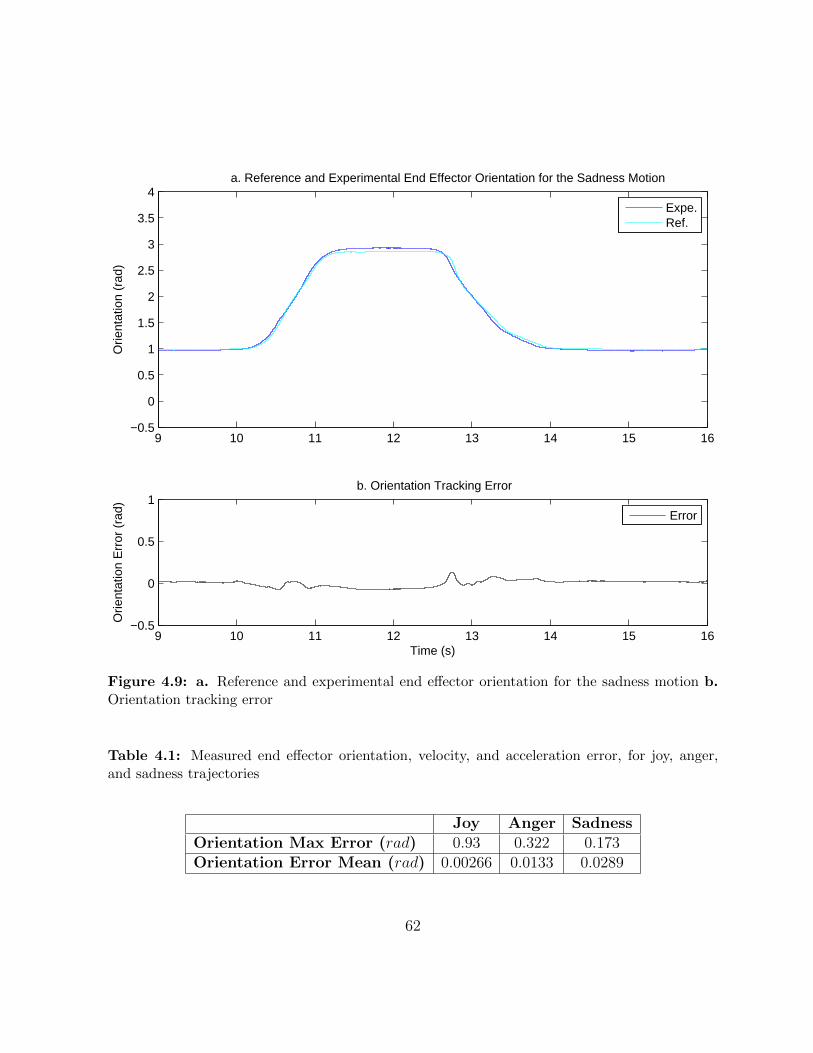
9 10 11 12 13 14 15 16−0.5
0
0.5
1
1.5
2
2.5
3
3.5
4
Orie
ntat
ion
(rad
)
a. Reference and Experimental End Effector Orientation for the Sadness Motion
Expe.Ref.
9 10 11 12 13 14 15 16−0.5
0
0.5
1
Time (s)
Orie
ntat
ion
Err
or (
rad)
b. Orientation Tracking Error
Error
Figure 4.9: a. Reference and experimental end effector orientation for the sadness motion b.Orientation tracking error
Table 4.1: Measured end effector orientation, velocity, and acceleration error, for joy, anger,and sadness trajectories
Joy Anger SadnessOrientation Max Error (rad) 0.93 0.322 0.173Orientation Error Mean (rad) 0.00266 0.0133 0.0289
62
Figures 4.10, 4.11, and 4.12 show the end effector’s angular velocities for the motiontrajectories conveying joy, anger, and sadness respectively. The corresponding trackingerrors are also presented at the bottom of each figure. The angular velocity is calculatedfrom the measured orientation using discrete differentiation in Simulink. Looking at thepeak velocity tracking errors, it can be deduced that the peaks occur during higher velocityclosing and opening motions of anger and joy. These error peaks are mainly related to thedifferent velocity profiles of the SPAM actuator and the human finger. For example, inthe orientation trajectory plot of joy (figure 4.7), it can be observed that the humanfinger has a concave-down trajectory while the SPAM has a concave-up trajectory. As thevelocity plot confirms, to reach the same orientation value the finger accelerates quicklyand decelerates slowly while the SPAM accelerates slowly and decelerates quickly. Thisdiscrepancy in acceleration and deceleration behaviours results in tracking error during theclosing motion.
The velocity plots also show that especially during the motion trajectory for sadness,high frequency vibrations are present. These vibrations are due to the PWM signaling ofthe valve. The velocity vibrations have zero mean and as the orientation plots confirm,they do not show up in the orientation change of the end effector and thus are not a concernin terms of interfering with affective capabilities of the motions. The vibrations make theacceleration plots of the motion trajectories very noisy and significantly reduce the ana-lytical merit of the acceleration tracking performance. Therefore, only maximum achievedangular accelerations are discussed and acceleration tracking error is not considered.
63

10.5 11 11.5 12 12.5 13 13.5 14 14.5 15−30
−25
−20
−15
−10
−5
0
5
10
Vel
ocity
(ra
d/s)
a. Reference and Experimental End Effector Angular Velocity for the Joy Motion
Expe.Ref.
10.5 11 11.5 12 12.5 13 13.5 14 14.5 15−10
−5
0
5
10
Time (s)
Vel
ocity
Err
or (
rad/
s)
b. Angular Velocity Tracking Error
Figure 4.10: a. Reference and experimental end effector angular velocity for the joy motion b.Angular velocity tracking error
64
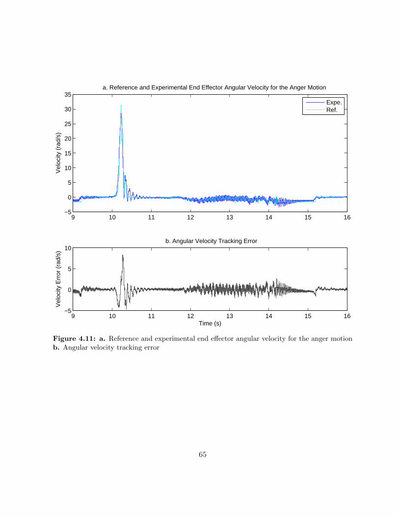
9 10 11 12 13 14 15 16−5
0
5
10
15
20
25
30
35
Vel
ocity
(ra
d/s)
a. Reference and Experimental End Effector Angular Velocity for the Anger Motion
Expe.Ref.
9 10 11 12 13 14 15 16−5
0
5
10
Time (s)
Vel
ocity
Err
or (
rad/
s)
b. Angular Velocity Tracking Error
Figure 4.11: a. Reference and experimental end effector angular velocity for the anger motionb. Angular velocity tracking error
65
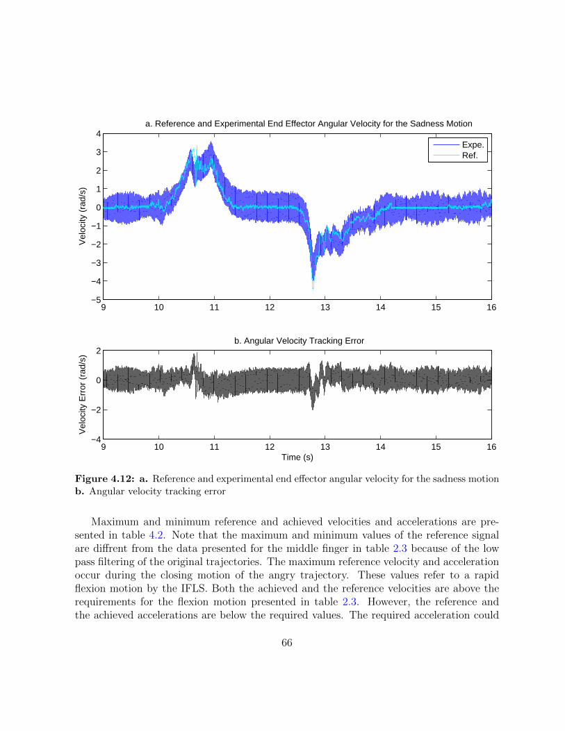
9 10 11 12 13 14 15 16−5
−4
−3
−2
−1
0
1
2
3
4
Vel
ocity
(ra
d/s)
a. Reference and Experimental End Effector Angular Velocity for the Sadness Motion
Expe.Ref.
9 10 11 12 13 14 15 16−4
−2
0
2
Time (s)
Vel
ocity
Err
or (
rad/
s)
b. Angular Velocity Tracking Error
Figure 4.12: a. Reference and experimental end effector angular velocity for the sadness motionb. Angular velocity tracking error
Maximum and minimum reference and achieved velocities and accelerations are pre-sented in table 4.2. Note that the maximum and minimum values of the reference signalare diffrent from the data presented for the middle finger in table 2.3 because of the lowpass filtering of the original trajectories. The maximum reference velocity and accelerationoccur during the closing motion of the angry trajectory. These values refer to a rapidflexion motion by the IFLS. Both the achieved and the reference velocities are above therequirements for the flexion motion presented in table 2.3. However, the reference andthe achieved accelerations are below the required values. The required acceleration could
66

Table 4.2: Maximum and minimum end effector orientation, velocity, and acceleration, for joy,anger, and sadness trajectories
Reference Achieved ErrorMax Velocity (rad/s) 31.5 28.6 2.89Min Velocity (rad/s) -28.2 -28.3 -0.0338Max Acceleration (rad/s2) 551 607 -55.2Min Acceleration (rad/s2) -664 -757 -92.4
be achieved by low pass filtering the reference trajectory at higher frequencies and usinghigher PID gains for the controller. However, higher bandwidth for the LPF of the ref-erence signal reduced the smoothness of the motion and the higher PID gains producedundesirable overshoot. These artifacts were more distracting than the error in maximumacceleration. The minimum velocity and acceleration occur during the opening motion ofthe joy trajectories. These values refer to a rapid extension motion by the IFLS. Both theachieved and the reference velocities and accelerations are above the requirements for theextension motion presented in table 2.3.
The plots in figure 4.13 present the reference and response trajectories where maximumand minimum velocities and accelerations occur. These plots suggest that the controllercan follow the reference velocity and acceleration profiles at critical parts of the trajectories.
67
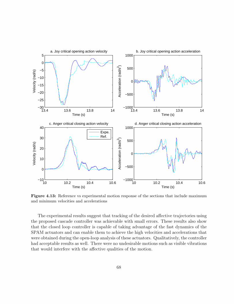
13.4 13.6 13.8 14−30
−25
−20
−15
−10
−5
0
5
Time (s)
Vel
ocity
(ra
d/s)
a. Joy critical opening action velocity
13.4 13.6 13.8 14−1000
−500
0
500
1000
Time (s)
Acc
eler
atio
n (r
ad/s
2 )
b. Joy critical opening action acceleration
10 10.2 10.4 10.6−10
0
10
20
30
40
Time (s)
Vel
ocity
(ra
d/s)
c. Anger critical closing action velocity
Expe.Ref.
10 10.2 10.4 10.6−1000
−500
0
500
1000
Time (s)
Acc
eler
atio
n (r
ad/s
2 )d. Anger critical closing action acceleration
Figure 4.13: Reference vs experimental motion response of the sections that include maximumand minimum velocities and accelerations
The experimental results suggest that tracking of the desired affective trajectories usingthe proposed cascade controller was achievable with small errors. These results also showthat the closed loop controller is capable of taking advantage of the fast dynamics of theSPAM actuators and can enable them to achieve the high velocities and accelerations thatwere obtained during the open-loop analysis of these actuators. Qualitatively, the controllerhad acceptable results as well. There were no undesirable motions such as visible vibrationsthat would interfere with the affective qualities of the motion.
68

Chapter 5
WSPAM1
The production methods for SPAMs such as PneuNets [67] and SPA [73] require relativelycomplex molds for producing the elastic hollow core of the actuator. The bend trajectory ofthese actuators is mainly determined by the relative elasticity of the component materialsand the mold design. This allows for a repeatable production method for these actuators.However, because elements such as the fiber in the FMA or the threading in the PneuFlexare not present, there is visible bloating and overstreching during bending. This behaviourcan be both visually unappealing and can also accelerate the mechanical degradation ac-tuator. Modifications to the motion trajectory of these actuators can also be relativelycumbersome and complex as they require modifications to the mold of the elastic material.FMA [72] and PneuFlex [69] designs do not suffer from bloating behaviours, however thethreading or inclusion of fiber makes the production method very complex and acceptablereproducibility in manufacturing is difficult to achieve.
In this chapter of the thesis, a novel design for SPAMs called wrapped SPAM (WSPAM)is introduced. The WSPAM design produces SPAMs with no bloating behaviours, a highlyrepeatable manufacturing process, and an easily modifiable motion profile. The WSPAMdesign consists of a simple silicone hollow core and a customizable silk mesh wrapping. Wedevelop a model relating the steady-state range of motion of the WSPAM to the cuttingpattern on the silk mesh wrapping. The model is based on the geometry of the cuttingpattern and the elastic properties of the silicone material. A procedure for extracting theparameters of the model is presented. Using the extracted parameters, the proposed modelis validated through experiments on WSPAM prototypes, and shown to predict the motionrange accurately.
1An early version of this chapter has been submitted to IROS 2015
69

5.1 WSPAM Production Process
In this section, we introduce the WSPAM design and describe its production process. AnWSPAM prototype is shown in figure 5.1.
θb
θtip
Figure 5.1: Cuboid WSPAM in the unpressurised and pressurized state. The silicone gap(white) and mesh cover (grey) pair block is shown on the left
WSPAMs achieve bending motion trajectories similarly to PneuFlex [69] and SPA [73]by utilizing a flexible non-elastic element such as a silk mesh to partially cover its outersurface and cause bending. The novelty in the design of WSPAMs is to wrap the entireouter surface of the hollow elastic core with a purpose-cut silk mesh. The cut patterns aredesigned such that different sections of the resulting WSPAM will acquire different effectiveelasticities. This difference in the elasticities will result in different motion trajectories in3D space. For example, in the case of the cuboid WSPAMs illustrated in figure 5.1, one ofthe four vertical surfaces and the surface of the tip are entirely covered with silk mesh. Thethree remaining vertical surfaces are covered by horizontal strips of silk mesh. The verticalsurface entirely covered with silk mesh will cause the WSPAM to bend and the silk meshstrips on the other three vertical surfaces will prevent bloating. The geometrical parametersof the stripe pattern determine the motion profile of the WSPAM and are easily modifiableduring fabrication. This makes it easy to construct WSPAMs with different motion profiles.From this point on, WSPAM will refer to cuboid WSPAMs with horizontal stripe patternssimilar to the WSPAM depicted in figure 5.1.
70

The mold for producing the hollow cuboid core of the WSPAM is implemented usingLEGO pieces and plexiglass. Using LEGO pieces in the design of the mold provides severaladvantages over prototyping methods such as using 3D printers. LEGO-built structures,unlike 3D printed structures, have smooth surfaces and as the negatives for the surface ofthe molded silicone, this results in a smooth surface on the molded silicone structure. Thesizing standard for LEGOs provides a platform that enables rapid production of variousalignment and fixating apparatuses, as will be demonstrated in the following paragraphs.It also results in a standard molded silicone that is compatible with LEGO-built structures.While not as modifiable as 3D-printed molds, LEGO-built molds are also very modifiableand various designs can be experimented with in order to determine the most suitablemold design. Figure 5.2 shows the outer section of the mold for the silicone hollow core.Two of the four walls of the mold are built using plexiglass. This is for two reasons: first,to reduce the number of LEGO pieces, and second, to make the mold transparent so thedegassing process, which will be explained further in the text, can be observed more easily.
Figure 5.2: LEGO-built outer mold with plexiglass covers
71
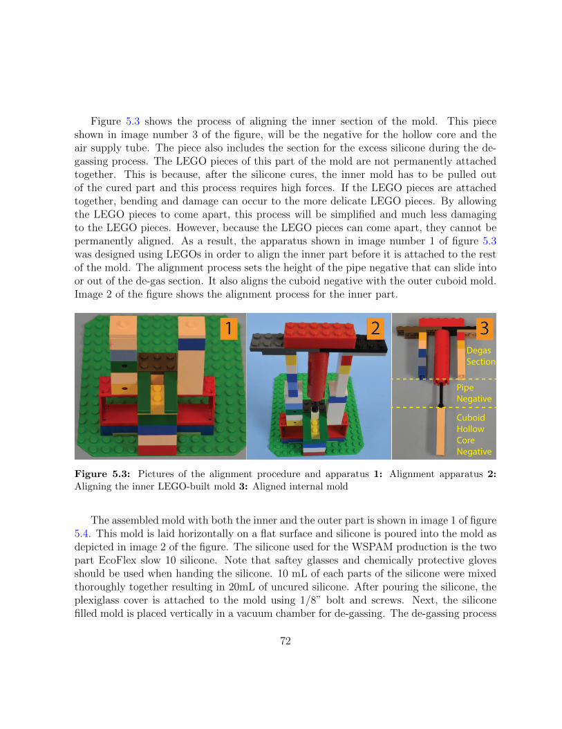
Figure 5.3 shows the process of aligning the inner section of the mold. This pieceshown in image number 3 of the figure, will be the negative for the hollow core and theair supply tube. The piece also includes the section for the excess silicone during the de-gassing process. The LEGO pieces of this part of the mold are not permanently attachedtogether. This is because, after the silicone cures, the inner mold has to be pulled outof the cured part and this process requires high forces. If the LEGO pieces are attachedtogether, bending and damage can occur to the more delicate LEGO pieces. By allowingthe LEGO pieces to come apart, this process will be simplified and much less damagingto the LEGO pieces. However, because the LEGO pieces can come apart, they cannot bepermanently aligned. As a result, the apparatus shown in image number 1 of figure 5.3was designed using LEGOs in order to align the inner part before it is attached to the restof the mold. The alignment process sets the height of the pipe negative that can slide intoor out of the de-gas section. It also aligns the cuboid negative with the outer cuboid mold.Image 2 of the figure shows the alignment process for the inner part.
Degas
Section
Pipe
Negative
Cuboid
Hollow
Core
Negative
Figure 5.3: Pictures of the alignment procedure and apparatus 1: Alignment apparatus 2:Aligning the inner LEGO-built mold 3: Aligned internal mold
The assembled mold with both the inner and the outer part is shown in image 1 of figure5.4. This mold is laid horizontally on a flat surface and silicone is poured into the mold asdepicted in image 2 of the figure. The silicone used for the WSPAM production is the twopart EcoFlex slow 10 silicone. Note that saftey glasses and chemically protective glovesshould be used when handing the silicone. 10 mL of each parts of the silicone were mixedthoroughly together resulting in 20mL of uncured silicone. After pouring the silicone, theplexiglass cover is attached to the mold using 1/8” bolt and screws. Next, the siliconefilled mold is placed vertically in a vacuum chamber for de-gassing. The de-gassing process
72

is depicted in image 3 of figure 5.4.
Figure 5.4: Pictures of the silicone molding procedure 1: Assembled mold 2: Pouring thesilicone into the mold 3: De-gassing of the silicone
Figure 5.5 demonstrates the process of cutting the silk mesh and aligning and fixatingthe mesh to the silicone core. First, the silk mesh is placed on the cutting plate of the lasercutter and is colored black using diluted water-soluble color such as acrylic paint. Themesh is colored black so that it can absorb more laser energy and thus can be cut withlower power lasers. The coloring with diluted color also ensures that the mesh does nothave any waves and is smoothly and flatly stuck to the cutting plate of the laser cutter.Note that other flexible materials that are not stretchable and can be cut with a lasercutter can be used instead of silk mesh. As shown in image 1 of the figure, after thecolor dries, the laser cutter cuts the desired WSPAM pattern on the mesh. A sample cutpattern is illustrated in figure 5.6. In the figure, red lines demonstrate the lines the lasercutter needs to cut. W is the width of silicone wall at the tip. Hg is the height of the gapsection. Hc is the height of the cover section. L is the width of the cuboid silicone coreof the WSPAM. LO is the overlapped portion of the uncut mesh which will become themotion restricting portion of wrapping that causes bending. The laser cutter is custombuilt from scrap computer peripherals. The laser diode is extracted from a DVD writer,and mounted on a laser diode housing. A CPU heatsink is modified to be used for coolingthe laser diode, purchased online. The laser diode module is attached to a 2D CNC whichis built using stepper motors from scrapped scanners and printers. Note that proper laserprotection eye wear has to be used during the operation of the laser cutter.
73
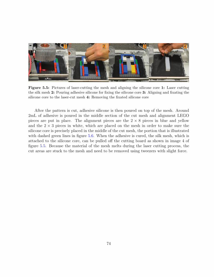
Figure 5.5: Pictures of laser-cutting the mesh and aligning the silicone core 1: Laser cuttingthe silk mesh 2: Pouring adhesive silicone for fixing the silicone core 3: Aligning and fixating thesilicone core to the laser-cut mesh 4: Removing the fixated silicone core
After the pattern is cut, adhesive silicone is then poured on top of the mesh. Around2mL of adhesive is poured in the middle section of the cut mesh and alignment LEGOpieces are put in place. The alignment pieces are the 2 × 8 pieces in blue and yellowand the 2 × 3 pieces in white, which are placed on the mesh in order to make sure thesilicone core is precisely placed in the middle of the cut mesh, the portion that is illustratedwith dashed green lines in figure 5.6. When the adhesive is cured, the silk mesh, which isattached to the silicone core, can be pulled off the cutting board as shown in image 4 offigure 5.5. Because the material of the mesh melts during the laser cutting process, thecut areas are stuck to the mesh and need to be removed using tweezers with slight force.
74

L/2<LO<L3L
W
Hg
Hb
Silk Mesh
L/2<LO<L
Figure 5.6: Sample laser cut pattern for WSPAM. The red line indicates the lines the lasercutter needs to cut.
Using the jig in image 1 of figure 5.7, the silk mesh is completely wrapped around thesilicone core. Notice the uncut part of the mesh sticking out of the jig which is the motionrestricting side of the WSPAM that causes it to perform bending motion. This part alsoincludes the mesh cover for the tip of the WSPAM. About 6mL of adhesive silicone ispoured on the three naked vertical faces of the silicone core. After the mesh and the core
75
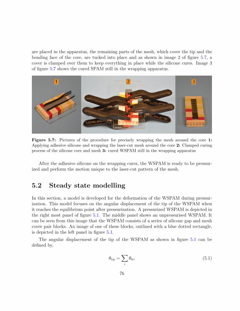
are placed in the apparatus, the remaining parts of the mesh, which cover the tip and thebending face of the core, are tucked into place and as shown in image 2 of figure 5.7, acover is clamped over them to keep everything in place while the silicone cures. Image 3of figure 5.7 shows the cured SPAM still in the wrapping apparatus.
Figure 5.7: Pictures of the procedure for precisely wrapping the mesh around the core 1:Applying adhesive silicone and wrapping the laser-cut mesh around the core 2: Clamped curingprocess of the silicone core and mesh 3: cured WSPAM still in the wrapping apparatus
After the adhesive silicone on the wrapping cures, the WSPAM is ready to be pressur-ized and perform the motion unique to the laser-cut pattern of the mesh.
5.2 Steady state modelling
In this section, a model is developed for the deformation of the WSPAM during pressur-ization. This model focuses on the angular displacement of the tip of the WSPAM whenit reaches the equilibrium point after pressurization. A pressurized WSPAM is depicted inthe right most panel of figure 5.1. The middle panel shows an unpressurised WSPAM. Itcan be seen from this image that the WSPAM consists of a series of silicone gap and meshcover pair blocks. An image of one of these blocks, outlined with a blue dotted rectangle,is depicted in the left panel in figure 5.1.
The angular displacement of the tip of the WSPAM as shown in figure 5.1 can bedefined by,
θtip =∑i
θbi, (5.1)
76

with θbi being the angular displacement of the ith block. Therefore, in order to model theangular displacements of the tip of the WSPAMs, the angular displacement of the gap andcover blocks needs to be modelled.
The gap and cover block of the WSPAMs is a hollow cuboid piece of silicone partiallycovered with silk mesh. Figure 5.8 illustrates the cross-sectional area of the WSPAM, withwall width W and wall length L. Figure 5.9 illustrates the side views of an unpressurisedand pressurized block. The block is divided into two stacked sections. The top sectionis covered by silk mesh on all four vertical sides and has height Hc. The gap section iscovered by silk mesh on one vertical side and has height Hg. The height of the block istherefore Hb = Hg +Hc. On the right side of figure 5.9, the pressurized state of the blockis illustrated, depicting the forces that the block experiences and their resulting net torqueand angular displacement.
L
L
W
+r
dk1
F1
dk2
W
F2
F3
F4
dk3
dk4
Figure 5.8: Parameters of the gap and cover block from top view. W is the thickness of thesilicone wall, L is the width of the WSPAM with a square cross section.
77
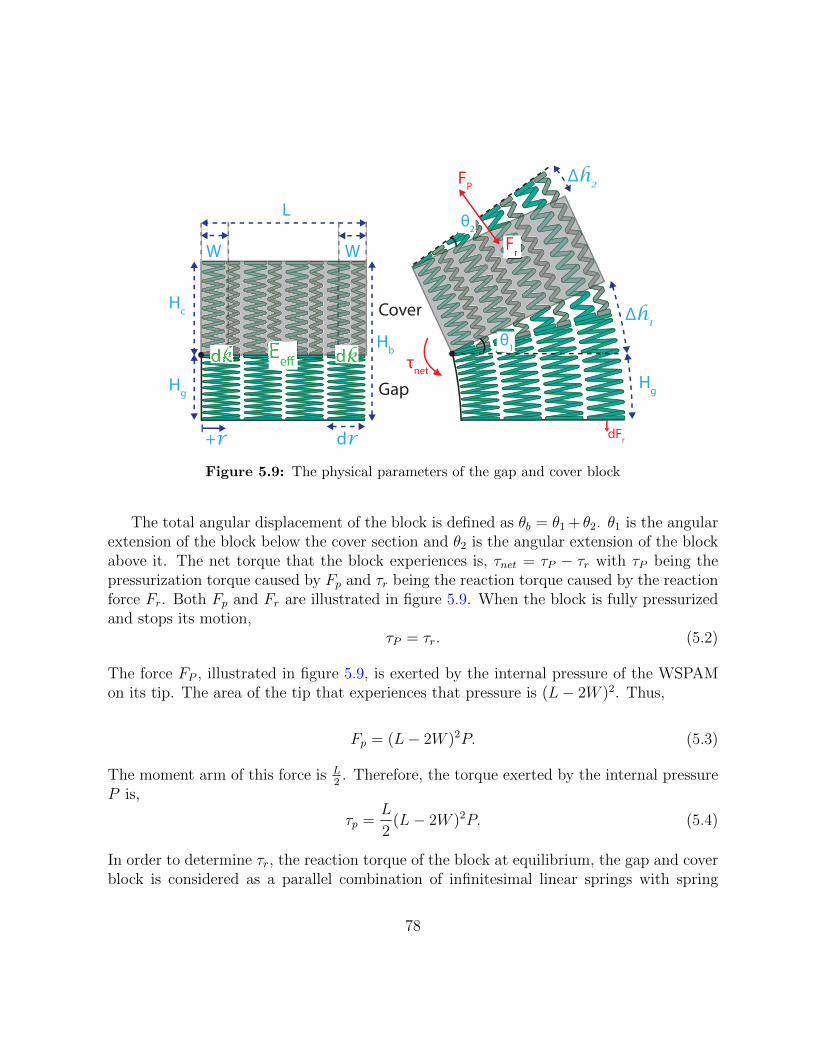
Hg
Hc
dr+r
Hg
Δh2
Δh1
θ1
Lθ2
dk
WW
FP
Fr
dFr
τnet
dk
Cover
Gap
HbE
e#
Figure 5.9: The physical parameters of the gap and cover block
The total angular displacement of the block is defined as θb = θ1 + θ2. θ1 is the angularextension of the block below the cover section and θ2 is the angular extension of the blockabove it. The net torque that the block experiences is, τnet = τP − τr with τP being thepressurization torque caused by Fp and τr being the reaction torque caused by the reactionforce Fr. Both Fp and Fr are illustrated in figure 5.9. When the block is fully pressurizedand stops its motion,
τP = τr. (5.2)
The force FP , illustrated in figure 5.9, is exerted by the internal pressure of the WSPAMon its tip. The area of the tip that experiences that pressure is (L− 2W )2. Thus,
Fp = (L− 2W )2P. (5.3)
The moment arm of this force is L2. Therefore, the torque exerted by the internal pressure
P is,
τp =L
2(L− 2W )2P. (5.4)
In order to determine τr, the reaction torque of the block at equilibrium, the gap and coverblock is considered as a parallel combination of infinitesimal linear springs with spring
78

constant dk. An effective Young’s modulus Eeff is assigned to the gap and cover block inorder to define dk in terms of the geometrical parameters of the block. Eeff is assumed tobe uniform along the cross sectional area of the block. The infinitesimal spring constant dkis determined by multiplying Eeff by its infinitesimal cross sectional area and dividing byits constant height Hb. Note that Eeff of the block is different from the Young’s modulusof the silicone alone because the cover mesh has a considerable effect on the elasticity ofthe silicone. The effects of the mesh cover on the elasticity of the hollow silicone core willbe discussed in section 5.3.
As illustrated in figure 5.8, the dk in each wall of the WSPAM is defined separately.Equations 5.5 and 5.6 define these spring constants along the r axis, illustrated in figure5.8.
dk1 = dk2 = EeffL− 2W
Hb
dr (5.5)
dk3 = dk4 = EeffW
Hb
dr (5.6)
The infinitesimal force exerted by each of the spring blocks can be defined as dFi = ∆h dki,where ∆h = ∆h1 + ∆h2 is the total amount of extension of the block, as illustrated infigure 5.9. The extension at any point along the r axis is,
∆h = rθ1 + rθ2 = rθb. (5.7)
The force Fi, as shown in figure 5.8, exerted by each wall is thus the integration of dFialong the r axis. Since the moment arm along the r axis is perpendicular to these forces,the resulting infinitesimal torque is,
dτi = r × dFi = r × ∆hdki = r2θb dki. (5.8)
Thus the resulting torques from each wall are,
79

τ1 =
∫ W
0
EeffθbL− 2W
Hb
r2dr
= EeffθbL− 2W
Hb
∫ W
0
r2dr
=Eeffθb(L− 2W )
3Hb
r3∣∣∣W0
=Eeffθb(L− 2W )W 3
3Hb
(5.9)
τ2 =Eeffθb(L− 2W )
3Hb
r3∣∣∣LL−W
=Eeffθb(L− 2W )(L3 − (L−W )3)
3Hb
(5.10)
and for τ3 and τ4 the dks from equation 5.6 result in,
τ3 = τ4 =EeffWθb
3Hb
r3∣∣∣L0
=EeffθbWL3
3Hb
(5.11)
Therefore, the total amount of torque τr exerted by the silicone is,
τr = τ1 + τ2 + τ3 + τ4
=Eeffθb3Hb
(2WL3 + (L− 2W )(W 3 + (L3 − (L−W )3)))
=EeffθbHb
f(L,W )
(5.12)
Thus, at equilibrium, using equations 5.4 and 5.12 results in, L2(L−2W )2P =
EeffθbHb
f(L,W ).Isolating θb,
80

θb =PHb
Eeffg(L,W ) where,
g(L,W ) =L(L− 2W )2
2f(L,W ).
(5.13)
Equation 5.13 shows that the amount of motion provided by the gap and cover block isdependent on five parameters: the effective Young’s modulus of the block Eeff , internalpressure P , and the geometrical parameters, L ,W , and Hb. P is the independent variableand will be the control signal for the position control of WSPAM actuators. Geometricalparameters L and W are determined by the mold that is used for constructing the hollowsilicone core and their modification requires changes to the silicone mold. Eeff and Hb aredetermined by the design of the wrapping fabric which can be modified much more easilythan the silicone mold. It should be noted that Eeff depends on both the wrapping andthe Young’s modulus of the silicone used. To simplify the analysis of the effect of Eeffand Hb on the angular displacement of the block, the L and W parameters are assumedconstant and are substituted into function g to give C = g(Lo,Wo). Thus, equation 5.13simplifies to,
θb = CPHb
Eeff. (5.14)
5.3 Modelling the Effective Young’s Modulus
In the development above, an effective Young’s modulus Eeff was defined for the entiregap and cover block. In this section, we derive the characteristics of Eeff in more detail.The formulation in Section 5.2 allowed for the definition of the spring constant dk in termsof the geometrical parameters of the infinitesimal linear spring. The infinitesimal springitself can be represented by a series combination of two linear springs, similar to the springsystem depicted in figure 5.10. One spring represents the cover section and one representsthe gap section of the block. The associated Young’s moduli of the springs of the cover andgap sections are represented by Ec and Eg respectively. This results in respective springconstants,
Kc =EcAoHc
(5.15)
81

Kg =EgAoHg
. (5.16)
Where A0 is the cross sectional area of the spring system. While A0 varies depending onthe specific wall geometry, it is constant in each of equations 5.15 and 5.16, and in Figure5.10, for a given wall of the WSPAM.
Hc
Hg
Eg
EC
Hb
Silk
Mesh
Silicone
Figure 5.10: The left-hand drawing shows a side view of one cover-gap pair block when pres-surized and the right-hand drawing shows the equivalent spring model. Bending of the block wasnot depicted for illustration purposes
82

The effective spring constant of the block can be defined as
Keff =EeffAoHb
. (5.17)
Since the springs representing the cover and gap sections are in series, the effective springconstant of the block can also be defined as,
Keff =KgKc
Kg +Kc
. (5.18)
Substituting 5.16 and 5.15 into equation 5.18 results in,
Keff =EcEgAo
EcHg + EgHc
. (5.19)
Equating equation 5.17 with equation 5.19 and isolating for Eeff results in,
Eeff =EcEgHb
EcHg + EgHc
. (5.20)
Substituting equation 5.20 into equation 5.14 results in,
θb = CPHg
Eg+ CP
Hc
Ec. (5.21)
Intuitively, the covered section is not as elastic as the gap section, therefore Eg < Ec. Phys-ical experiments were performed next to determine if this model is a good representationof the WSPAM spring block and also to estimate values for Ec and Eg.
During the initial stage of the experimental verification of the model for the WSPAMspring system, it was discovered that as Hc is increased, there is a critical height Hs beyondwhich the Young’s modulus of the cover section switches to a higher value. Figure 5.11depicts the case when Hc > Hs. This figure illustrates that when Hc > Hs, the middlepart of the silicone behind the cover mesh, which is depicted in light blue in the figure,does not contribute to the elasticity of the cover section as much as the end sections of thesilicone, depicted in red. This behaviour of the cover section can be modelled as a systemof springs depicted on the right side of figure 5.11. The middle section silicone can bemodelled as a parallel spring system of the mesh and silicone with Young’s moduli Em and
83

E ′c respectively. The silk mesh is non-elastic meaning its Young’s modulus Em is large i.e.Em >> E ′c. Thus the Young’s modulus of middle section is, Em + E ′c ≈ Em. The springrepresenting the middle section is in series with two springs at both ends that represent theend sections of the covered silicone. Thus, when Hc < Hs, there is no middle section siliconeand the Young’s modulus stays at Ec. However when the rest height reaches Hc > Hs,the cover section switches to a series spring system. This means for Hc > Hs the blockconsists of a series configuration of three types of springs. In other words, equation 5.21can be extended to,
θb = CPHg
Eg+ CP
Hs
Ec+ CP
Hc −Hs
Emfor Hc > Hs. (5.22)
84

HS/2
Hc
HS/2
Hg
Eg
Ec
Ec’ E
m
Hb
Silk
Mesh
Silicone
Ec
Figure 5.11: Cover section saturation model for the spring constant and the illustration of thesilicone behaviour when pressurized (Note, in reality the block would bend, the bending was notdepicted for illustration purposes)
85

5.4 Experimental Validation
In order to examine the prediction accuracy of the models discussed in the previous section,two different experimental procedures were designed and carried out. The first procedure,which was designed to estimate the parameters in the model, involved the production ofgradient WSPAMs, with gradually increasing gap or cover section heights. These WSPAMsprovided the ability to test multiple cover or gap heights in one WSPAM. Figure 5.12 showsthe two gradient WSPAMs that were designed for this experiment.
Figure 5.12: Gradient Hc (on the left) and Hg (on the right) WSPAMs at rest and pressurized
There are 6 collected data points for varying cover section heights and 4 data points forvarying gap section heights. Note that the angles of the tip gaps were not included as theyare not fully over the hollow core of the WSPAM, and include part of the WSPAM thatis solid silicone. The heights were recorded as the number of associated steps of the CNClaser cutter which produced the wrapping, with each step approximately equal to 0.42mm.The angles of the discrete gap-cover blocks are measured from the recorded images usingAdobe Illustrator. In all experiments, the geometrical parameters L and W were kept thesame between WSPAMs in order to keep C constant. In addition, the operating pressureduring each experiment was recorded using an electronic pressure sensor. Since there isa linear relationship between θb and P , as shown in equation 5.21, the measured angulardisplacements were normalized with respect to operating pressure.
Figure 5.13 illustrates the 4 data points for the cover gradient WSPAM (see figure 5.12,left) at constant Hc = 8 and variable Hg = 8, 12, 16, and 20. using equation 5.21 as themodel, which indicates a linear relationship between θ and Hg, a line is fitted through theexperimental data points with Hg as the independent variable. The fitted line is illustratedin figure 5.13. The root mean square error (RMSE) of the fit is 0.0541. With respect toequation 5.21 the slope of the fit is CP
Eg= 0.034.
86

6 8 10 12 14 16 18 20 22
0.2
0.3
0.4
0.5
0.6
0.7
Rest Height Hg
Ang
le θ
g (ra
d)
Fitted ModelExperimental θ
g
Figure 5.13: Simulation and experimental data for Kg in terms of rest heights Hg
Figure 5.14 illustrates the 6 data points for the gap gradient WSPAM (see figure 5.12,right) at constant Hg = 2 and variable Hc = 6, 8, 10, 12, 14 and 16. Fitting the developedmodel for variable Hc is more complex as it involves the determination of the saturationheight Hs. Observing the data points collected for variable Hc heights, it can be observedthat the saturation occurs somewhere between Hc = 8 and Hc = 12. A line was fittedthrough the first 3 data points which represent the unsaturated region for cover heightHc. Another line was fitted through the last 3 data points which represent the saturatedregion for cover height Hc. The point where these two line meet is the saturation height,Hs = 8.21. The fitted function is represented in figure 5.14. The RMSE of the fit is 0.0109.With respect to equation 5.21, the slope of the unsaturated region is CP
Ec= 0.0110. With
87
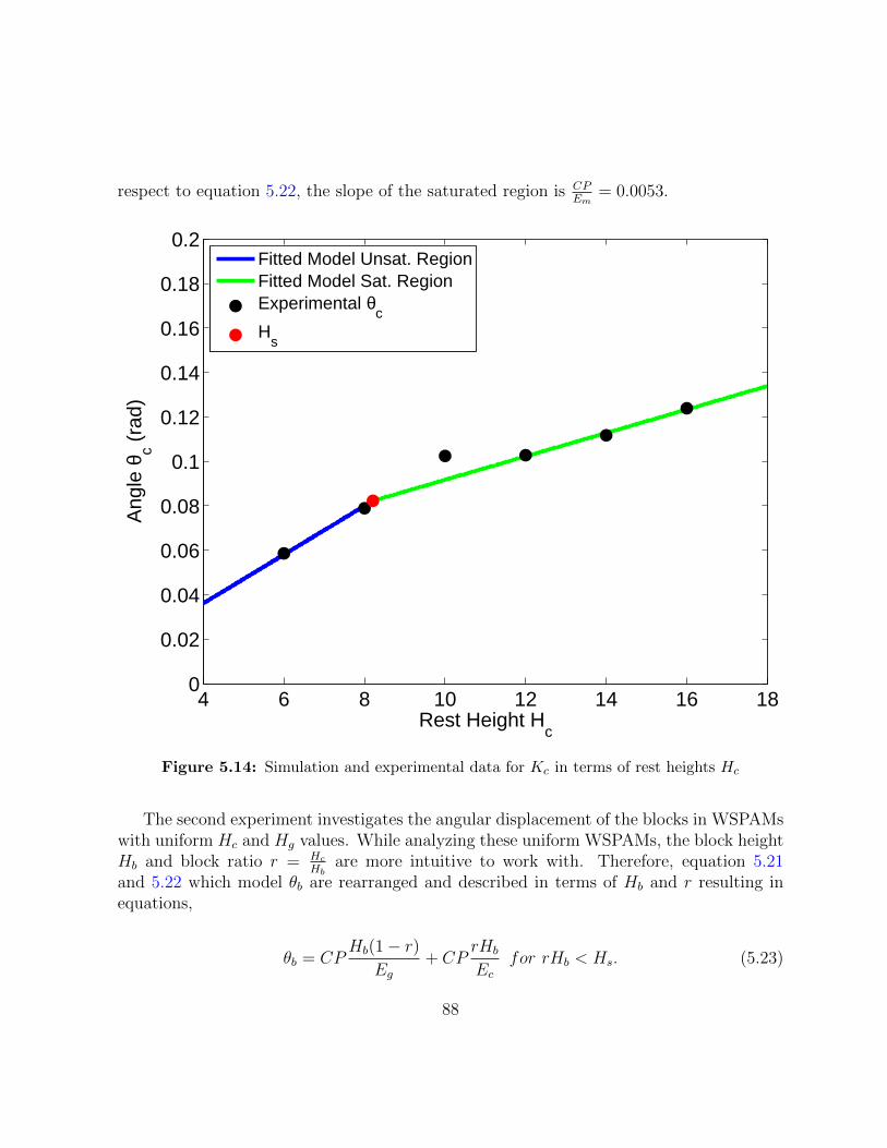
respect to equation 5.22, the slope of the saturated region is CPEm
= 0.0053.
4 6 8 10 12 14 16 180
0.02
0.04
0.06
0.08
0.1
0.12
0.14
0.16
0.18
0.2
Rest Height Hc
Ang
le θ
c (ra
d)
Fitted Model Unsat. RegionFitted Model Sat. RegionExperimental θ
cH
s
Figure 5.14: Simulation and experimental data for Kc in terms of rest heights Hc
The second experiment investigates the angular displacement of the blocks in WSPAMswith uniform Hc and Hg values. While analyzing these uniform WSPAMs, the block heightHb and block ratio r = Hc
Hbare more intuitive to work with. Therefore, equation 5.21
and 5.22 which model θb are rearranged and described in terms of Hb and r resulting inequations,
θb = CPHb(1 − r)
Eg+ CP
rHb
Ecfor rHb < Hs. (5.23)
88

θb = CPHb(1 − r)
Eg+ CP
Hs
Ec+ CP
rHb −Hs
Emfor rHb > Hs. (5.24)
Three r values of 1/4, 2/4, and 3/4 and two Hb values of 16 and 24 were tested in theexperiments. The constructed WSPAMs are illustrated in figure 5.15.
Figure 5.15: Pressurized WSPAMs at 3 different r and 2 different Hb values. Not that WSPAMswith lower r have higherHg and achieve greater angular displacment but at the cost of a distended,“bloated” appearance.
The angular displacements of the blocks of the WSPAMs were measured from theimages using Adobe Illustrator. The average of the measured displacement was assignedas the angular displacement of the block with the specific Hb and r values. The angulardisplacements were also normalized with respect to the internal pressure P . The resultingangular displacements are plotted in figure 5.16.
89

0.1 0.2 0.3 0.4 0.5 0.6 0.7 0.8 0.90.1
0.2
0.3
0.4
0.5
0.6
0.7
0.8
0.9
Cover to Block Height Ratio
Ang
luar
Dis
plac
emen
t (ra
d)
Hb = 16 exp.Hb = 16 sim. w/ sat.Hb = 16 sim. w/o sat.Hb = 24 exp.Hb = 24 sim. w/ sat.Hb = 24 sim. w/o sat.
Figure 5.16: Simulated and experimental block angular displacement θtip with respect to blockheight Hb and block ratio r in 2D
Figure 5.16 also includes the predicted block angular displacement from the modelin equations 5.23 and 5.24. Since C is kept constant and all the collected data pointsare normalized with respect to pressure, the fractions CP
Eg, CPEc
and CPEm
obtained from the
gradient WSPAM experiment can be used in equations 5.23 and 5.24 to model the angulardisplacement. The total RMSE of the simulation model versus the experimental data is0.099. The maximum error which occurs at r = 1/4 and Hb = 16 is 0.0679. These resultsdemonstrate a good fit between the model and the experimental data, showing that theproposed model can be used to predict the angular displacement as a function of the cutand cover pattern. In figure 5.16, results for the simpler model without taking saturation
90
into account are also illustrated. The simpler model achieves an RMSE of 0.113 with amaximum error of 0.0834. This shows that considering the saturation of the cover sectiondoes improve the prediction of the model.
The model presented in figure 5.16 suggests that during the design process of WSPAMactuators, in order to maximize the output angular displacement θb, block height Hb needsto be maximized and block ratio r needs to be minimized. This translates to minimizingcover height Hc while maximizing Hg. In a physical system however, there are restrictionson both the cover section height Hc and gap section height Hg. If bloating is undesirable,Hg should only be increased to heights that do not exhibit bloating at the desired workingpressures. Also, decreasing Hc too much can either cause the cover section to tear thesilicone over time or the silk mesh at those widths might not be able to withstand theapplied pressure and can break. Thus, a robust minimum cover height that does not causetear in the silicone and a maximum gap height that does not exhibit bloating has to beexperimentally determined at the desired working pressure.
91

Chapter 6
Conclusions
Inspired by interactive architecture works such as Hylozoic Soil shown in figure 1.1 thisthesis develops the design of an interactive finger-like structure called the IFLS, capable ofperforming motion affective motion trajectories. The design requirements of the IFLS weredetermined based on the characteristics of human affective motion and interactive archi-tecture applications. In comparison to conventional robotic hand designs, soft pneumaticartificial air muscles (SPAMs) were found more suitable for the design of the IFLS. WhileSPAMs held great potential for the application in this work, because they are a recentpneumatic actuation technology, a new production and control methodology needed to bedeveloped in order to fully exploit this potential.
Analysis of the open-loop response of the SPAMs demonstrated that these actuators arecapable of achieving fast dynamic motions. The first contribution of this paper was design-ing a closed-loop controller, capable of controlling the fast dynamic response of the SPAMactuator. Innovative designs enabled the application of PWM controller designs previouslyused for conventional PAM actuators. The innovative designs included providing feedbackon the orientation of the SPAM using a gyroscopic sensor, and introducing pneumatic lowpass filters and pull-down resistors in order to reduce the high noise levels caused by thePWM signaling in the pneumatic circuit. The implementation of the controller enabled theSPAM to perform affective motions which require high velocities and accelerations. Froma qualitative perspective, undesirable responses such as visible vibration were eliminated.
Experiments during the design and tuning of the controller suggested that flaws in thecurrent designs of SPAMs reduce their robustness in high-speed applications. Also, theircurrent production methods did not achieve consistent prototypes and were not easilycustomizable. This inspired the development of a novel SPAM design, WSPAMs, that
92

rectifies these issues. The production of WSPAMs uses laser-cut silk mesh wrapped arounda hollow silicone core. The specific cut pattern on the silk mesh determines the motiontrajectory of the actuator and its poses during the motion. The use of a laser cutterprovides for highly repeatable and precise fabrication, with parameters that are easilymodified. This results in a consistent, highly customizable actuator production method.
In addition to their production method, a model for the steady-state angular displace-ment of the WSPAMs was presented, which describes the relationship between the cutpattern and tip angular displacement, for a given finger geometry and working pressure.A procedure for estimating the parameters of the model was described. It was shownthat the model, using the estimated parameters, is capable of predicting the steady-statetip angular displacements with good accuracy. The model, together with physical designconstraints, can be used to design robust WSPAMs capable of achieving a desired angulardisplacement.
In future work, the dynamic model of WSPAM actuators will be investigated. This willallow for a better understanding of the velocity profile of these actuators and the amountof force and torque they can provide. The dynamic model of the WSPAMs can be used formore complex and nonlinear controller designs that can improve the trajectory-followingcapabilities of WSPAMs. In addition, the production method of the WSPAMs can bereevaluated with more industrial and volume production requirements in mind. Lastly,the WSPAM production method can be used for motion trajectories other than the finger-like curved motion investigated in this work. In future work, the existing model can begeneralized for the inclusion of alternative trajectory designs, and the closed-loop controldesign can be advanced to track general WSPAM designs.
Future work will also focus on the evaluation of the affective capabilities of the de-veloped actuators. Using the WSPAM actuator, IFLS mechanisms will be implementedthat perform the affective movements discussed in the thesis. The capability of the IFLSmechanism to convey the target emotions using movement will be investigated using userstudies. The user studies can also be used to attain a better understanding of the factorsthat influence affective perception. The IFLS mechanism and controller can be used tovary the intensity and variability of motion performance to investigate the sensitivity ofmotion and appearance factors on affective motion perception.
Lastly, the IFLS mechanism will be integrated into an interactive architecture installa-tion such as Hylozoic Soil [10]. The IFLS mechanism will be used as part of the interactivemechanism to generate affective movements as part of the interaction strategy. The abilityof the IFLS to convey affect when embedded in an interactive architecture environmentwill be analyzed.
93

Bibliography
[1] M. Karg, A.-A. Samadani, R. Gorbet, K. Kuhnlenz, J. Hoey, and D. Kulic, “Bodymovements for affective expression: a survey of automatic recognition and generation,”Affective Computing, IEEE Transactions on, vol. 4, no. 4, pp. 341–359, 2013.
[2] A. Kleinsmith and N. Bianchi-Berthouze, “Affective body expression perception andrecognition: A survey,” Affective Computing, IEEE Transactions on, vol. 4, no. 1,pp. 15–33, 2013.
[3] B. Allison, G. Nejat, and E. Kao, “The design of an expressive humanlike sociallyassistive robot,” Journal of Mechanisms and Robotics, vol. 1, no. 1, p. 011001, 2009.
[4] Y. Bar-Cohen and C. Breazeal, “Biologically inspired intelligent robots,” in SmartStructures and Materials, pp. 14–20, International Society for Optics and Photonics,2003.
[5] C. L. Breazeal, Designing sociable robots. MIT press, 2004.
[6] C. Breazeal, “Toward sociable robots,” Robotics and autonomous systems, vol. 42,no. 3, pp. 167–175, 2003.
[7] F. E. Pollick, H. M. Paterson, A. Bruderlin, and A. J. Sanford, “Perceiving affect fromarm movement,” Cognition, vol. 82, no. 2, pp. B51–B61, 2001.
[8] M. S. ADA, K. Suda, and M. Ishii, “Expression of emotions in dance: Relation betweenarm movement characteristics and emotion,” Perceptual and motor skills, vol. 97,no. 3, pp. 697–708, 2003.
[9] A.-A. Samadani, E. Kubica, R. Gorbet, and D. Kulic, “Perception and generationof affective hand movements,” International Journal of Social Robotics, vol. 5, no. 1,pp. 35–51, 2013.
94

[10] P. Beesley, “Hylozoic soil,” Leonardo, vol. 42, no. 4, pp. 360–361, 2009.
[11] J.-H. Lee, J.-Y. Park, and T.-J. Nam, “Emotional interaction through physical move-ment,” in Human-Computer Interaction. HCI Intelligent Multimodal Interaction En-vironments, pp. 401–410, Springer, 2007.
[12] M. Saerbeck and C. Bartneck, “Perception of affect elicited by robot motion,” in Pro-ceedings of the 5th ACM/IEEE international conference on Human-robot interaction,pp. 53–60, IEEE Press, 2010.
[13] HYLOZOIC SOIL, 2009.
[14] M. Controzzi, C. Cipriani, and M. C. Carrozza, “Design of artificial hands: A review,”in The Human Hand as an Inspiration for Robot Hand Development, pp. 219–246,Springer, 2014.
[15] J. Pons, E. Rocon, R. Ceres, D. Reynaerts, B. Saro, S. Levin, and W. Van Moor-leghem, “The manus-hand dextrous robotics upper limb prosthesis: mechanical andmanipulation aspects,” Autonomous Robots, vol. 16, no. 2, pp. 143–163, 2004.
[16] J. T. Belter, J. L. Segil, A. M. Dollar, and R. F. Weir, “Mechanical design andperformance specifications of anthropomorphic prosthetic hands: A review,” J RehabilRes Dev, vol. 50, no. 5, pp. 599–618, 2013.
[17] T. Takaki and T. Omata, “High-performance anthropomorphic robot hand withgrasping-force-magnification mechanism,” Mechatronics, IEEE/ASME Transactionson, vol. 16, no. 3, pp. 583–591, 2011.
[18] A.-A. Samadani, B. DeHart, K. Robinson, D. Kulic, E. Kubica, and R. Gorbet, “Astudy of human performance in recognizing expressive hand movements,” in RO-MAN,2011 IEEE, pp. 93 –100, 31 2011-aug. 3 2011.
[19] G. Stillfried, U. Hillenbrand, M. Settles, and P. van der Smagt, “Mri-based skele-tal hand movement model,” in The Human Hand as an Inspiration for Robot HandDevelopment, pp. 49–75, Springer, 2014.
[20] S. Montambault and C. M. Gosselin, “Analysis of underactuated mechanical grippers,”Journal of Mechanical Design, vol. 123, no. 3, pp. 367–374, 2001.
[21] V. Scheinman and J. McCarthy, “Mechanisms and actuation,” in Springer Handbookof Robotics (B. Siciliano and O. Khatib, eds.), pp. 67–86, Springer Berlin Heidelberg,2008.
95

[22] A. Namiki, Y. Imai, M. Ishikawa, and M. Kaneko, “Development of a high-speedmultifingered hand system and its application to catching,” in Intelligent Robots andSystems, 2003.(IROS 2003). Proceedings. 2003 IEEE/RSJ International Conferenceon, vol. 3, pp. 2666–2671, IEEE, 2003.
[23] RobotShop, Brushless DC Motors, April 2015. http://www.robotshop.com/ca/en/
bldc-motors.html.
[24] RobotShop, 24V, 58RPM, 138.87oz-in Brushless DC Gearmotor, April 2015. http://www.robotshop.com/ca/en/24v-58rpm-13887-oz-in-brushless-dc-gearmotor.
html.
[25] Pololu, 30:1 Metal Gearmotor 37Dx52L mm, Nov 2014. http://www.pololu.com/
product/1103.
[26] J. Jalani, G. Herrmann, and C. Melhuish, “Robust active compliance control forpractical grasping of a cylindrical object via a multifingered robot hand,” in Robotics,Automation and Mechatronics (RAM), 2011 IEEE Conference on, pp. 316–321, IEEE,2011.
[27] A. Parmiggiani, G. Metta, and N. Tsagarakis, “The mechatronic design of the newlegs of the icub robot,” in Humanoid Robots (Humanoids), 2012 12th IEEE-RASInternational Conference on, pp. 481–486, IEEE, 2012.
[28] I. W. Hunter, J. M. Hollerbach, and J. Ballantyne, “A comparative analysis of actuatortechnologies for robotics,” Robotics Review, vol. 2, 1991.
[29] S. Jacobsen, E. Iversen, D. Knutti, R. Johnson, and K. Biggers, “Design of theutah/mit dextrous hand,” in Robotics and Automation. Proceedings. 1986 IEEE In-ternational Conference on, vol. 3, pp. 1520–1532, IEEE, 1986.
[30] K. B. Fite, T. J. Withrow, K. W. Wait, and M. Goldfarb, “A gas-actuated anthropo-morphic transhumeral prosthesis,” in Robotics and Automation, 2007 IEEE Interna-tional Conference on, pp. 3748–3754, IEEE, 2007.
[31] B. Peerdeman, G. Smit, S. Stramigioli, D. Plettenburg, and S. Misra, “Evaluationof pneumatic cylinder actuators for hand prostheses,” in Biomedical Robotics andBiomechatronics (BioRob), 2012 4th IEEE RAS & EMBS International Conferenceon, pp. 1104–1109, IEEE, 2012.
[32] Festo, Airic’s Arm, 2007. http://www.festo.com/cms/en_corp/9785_10400.htm.
96

[33] R. Walkler, “Developments in dextrous hands for advanced robotic applications,” inProc. the Sixth Biannual World Automation Congress, Seville, Spain, pp. 123–128,2004.
[34] Y. Honda, F. Miyazaki, and A. Nishikawa, “Angle control of pneumatically-drivenmusculoskeletal model using antagonistic muscle ratio and antagonistic muscle activ-ity,” in Robotics and Biomimetics (ROBIO), 2010 IEEE International Conference on,pp. 1722 –1727, dec. 2010.
[35] S. Nishino, N. Tsujiuchi, T. Koizumi, H. Komatsubara, T. Kudawara, and M. Shimizu,“Development of robot hand with pneumatic actuator and construct of master-slavesystem,” in Engineering in Medicine and Biology Society, 2007. EMBS 2007. 29thAnnual International Conference of the IEEE, pp. 3027–3030, IEEE, 2007.
[36] D. Plettenburg, “Electric versus pneumatic power in hand prostheses for children,”Journal of medical engineering & technology, vol. 13, no. 1-2, pp. 124–128, 1989.
[37] D. Stoianovici, A. Patriciu, D. Petrisor, D. Mazilu, and L. Kavoussi, “A new type ofmotor: pneumatic step motor,” Mechatronics, IEEE/ASME Transactions on, vol. 12,no. 1, pp. 98–106, 2007.
[38] J. Huber, N. Fleck, and M. Ashby, “The selection of mechanical actuators based onperformance indices,” Proceedings of the Royal Society of London. Series A: Mathe-matical, Physical and Engineering Sciences, vol. 453, no. 1965, pp. 2185–2205, 1997.
[39] pro-dex, Air Motors. http://www.pro-dex.com/air-motors.aspx.
[40] G. Andrikopoulos, G. Nikolakopoulos, and S. Manesis, “A survey on applications ofpneumatic artificial muscles,” in Control & Automation (MED), 2011 19th Mediter-ranean Conference on, pp. 1439–1446, IEEE, 2011.
[41] H. Schulte, “The characteristics of the mckibben artificial muscle,” The application ofexternal power in prosthetics and orthotics, vol. 874, pp. 94–115, 1961.
[42] K. Suzumori, S. Wakimoto, K. Miyoshi, and K. Iwata, “Long bending rubber mecha-nism combined contracting and extending fluidic actuators,” in Intelligent Robots andSystems, 2013. IROS 2013. IEEE/RSJ International Conference on, IEEE, 2013.
[43] R. B. Van Varseveld and G. M. Bone, “Accurate position control of a pneumaticactuator using on/off solenoid valves,” Mechatronics, IEEE/ASME Transactions on,vol. 2, no. 3, pp. 195–204, 1997.
97

[44] M. Taghizadeh, A. Ghaffari, and F. Najafi, “Modeling and identification of a solenoidvalve for pwm control applications,” Comptes Rendus Mecanique, vol. 337, no. 3,pp. 131–140, 2009.
[45] V. Jouppila and A. Ellman, “Position control of pwm-actuated pneumatic muscleactuator system,” ASME Conference Proceedings, vol. 2011, no. 54938, pp. 393–404,2011.
[46] S. Schulz, C. Pylatiuk, M. Reischl, J. Martin, R. Mikut, and G. Bretthauer, “A hy-draulically driven multifunctional prosthetic hand,” Robotica, vol. 23, no. 03, pp. 293–299, 2005.
[47] K. Hoshino and W. Krishantha, “Calligraphic motion by humanoid robot arm usingair cylinder actuators as endoskeletons,” in Mechatronics, ICM2007 4th IEEE Inter-national Conference on, pp. 1–6, IEEE, 2007.
[48] K. Yang and C. Gu, “A novel robot hand with embedded shape memory alloy ac-tuators,” Proceedings of the Institution of Mechanical Engineers, Part C: Journal ofMechanical Engineering Science, vol. 216, no. 7, pp. 737–745, 2002.
[49] C. Y. Low, M. A. A. Kasim, T. Koch, R. Dumitrescu, H. Yussof, R. Jaafar, A. A.Ahmed Jaffar, and K. M. Ng, “Hybrid-actuated finger prosthesis with tactile sensing,”INTERNATIONAL JOURNAL OF ADVANCED ROBOTIC SYSTEMS, vol. 10,2013.
[50] R. B. Gorbet and R. A. Russell, “A novel differential shape memory alloy actuatorfor position control,” Robotica, vol. 13, no. 04, pp. 423–430, 1995.
[51] M. Liang and W. Zhang, “Analysis of coupled-active fingers with gear mechanism,”in Informatics in Control, Automation and Robotics, pp. 439–446, Springer, 2012.
[52] G. Li, H. Liu, and W. Zhang, “Development of multi-fingered robotic hand with cou-pled and directly self-adaptive grasp,” International Journal of Humanoid Robotics,vol. 9, no. 04, 2012.
[53] G. Li and W. Zhang, “Study on coupled and self-adaptive finger for robot hand withparallel rack and belt mechanisms,” in Robotics and Biomimetics (ROBIO), 2010IEEE International Conference on, pp. 1110–1115, IEEE, 2010.
[54] L.-R. Lin and H.-P. Huang, “Ntu hand: A new design of dexterous hands,” Journalof Mechanical Design, vol. 120, no. 2, pp. 282–292, 1998.
98
[55] H. Kawasaki, T. Komatsu, and K. Uchiyama, “Dexterous anthropomorphic robothand with distributed tactile sensor: Gifu hand ii,” Mechatronics, IEEE/ASMETransactions on, vol. 7, no. 3, pp. 296–303, 2002.
[56] T. Zhang, S. Fan, L. Jiang, and H. Liu, “Development and experiment analysis ofanthropomorphic prosthetic hand with flexible three-axis tactile sensor,” InternationalJournal of Humanoid Robotics, vol. 10, no. 03, 2013.
[57] M. Rakic, “An automatic hand prosthesis,” Medical electronics and biological engi-neering, vol. 2, no. 1, pp. 47–55, 1964.
[58] F. Lotti, P. Tiezzi, G. Vassura, L. Biagiotti, and C. Melchiorri, “Ubh 3: an anthropo-morphic hand with simplified endo-skeletal structure and soft continuous fingerpads,”in Robotics and Automation, 2004. Proceedings. ICRA’04. 2004 IEEE InternationalConference on, vol. 5, pp. 4736–4741, IEEE, 2004.
[59] A. M. Dollar and R. D. Howe, “The highly adaptive sdm hand: Design and per-formance evaluation,” The international journal of robotics research, vol. 29, no. 5,pp. 585–597, 2010.
[60] J. K. Salisbury and J. J. Craig, “Articulated hands force control and kinematic issues,”The International Journal of Robotics Research, vol. 1, no. 1, pp. 4–17, 1982.
[61] H. A. Baldwin, “Realizable models of muscle function,” in Biomechanics, pp. 139–147,Springer, 1995.
[62] F. Daerden and D. Lefeber, “Pneumatic artificial muscles: actuators for robotics andautomation,” European journal of mechanical and environmental engineering, vol. 47,no. 1, pp. 11–21, 2002.
[63] Y. S. Song, Y. Sun, R. Van Den Brand, J. Von Zitzewitz, S. Micera, G. Courtine, andJ. Paik, “Soft robot for gait rehabilitation of spinalized rodents,” in Intelligent Robotsand Systems (IROS), 2013 IEEE/RSJ International Conference on, pp. 971–976, Ieee,2013.
[64] P. Polygerinos, Z. Wang, K. C. Galloway, R. J. Wood, and C. J. Walsh, “Soft roboticglove for combined assistance and at-home rehabilitation,” Robotics and AutonomousSystems, 2014.
[65] G. Fantoni, M. Santochi, G. Dini, K. Tracht, B. Scholz-Reiter, J. Fleischer, T. K.Lien, G. Seliger, G. Reinhart, J. Franke, et al., “Grasping devices and methods in
99

automated production processes,” CIRP Annals-Manufacturing Technology, vol. 63,no. 2, pp. 679–701, 2014.
[66] C. Blanes, M. Mellado, and P. Beltran, “Novel additive manufacturing pneumaticactuators and mechanisms for food handling grippers,” in Actuators, vol. 3, pp. 205–225, Multidisciplinary Digital Publishing Institute, 2014.
[67] F. Ilievski, A. D. Mazzeo, R. F. Shepherd, X. Chen, and G. M. Whitesides, “Softrobotics for chemists,” Angewandte Chemie, vol. 123, no. 8, pp. 1930–1935, 2011.
[68] K. Suzumori, S. Iikura, and H. Tanaka, “Applying a flexible microactuator to roboticmechanisms,” Control Systems, IEEE, vol. 12, no. 1, pp. 21–27, 1992.
[69] R. Deimel and O. Brock, “A compliant hand based on a novel pneumatic actuator,” inRobotics and Automation (ICRA), 2013 IEEE International Conference on, pp. 2047–2053, IEEE, 2013.
[70] R. F. Shepherd, F. Ilievski, W. Choi, S. A. Morin, A. A. Stokes, A. D. Mazzeo,X. Chen, M. Wang, and G. M. Whitesides, “Multigait soft robot,” Proceedings of theNational Academy of Sciences, vol. 108, no. 51, pp. 20400–20403, 2011.
[71] K. Suzumori, S. Endo, T. Kanda, N. Kato, and H. Suzuki, “A bending pneumaticrubber actuator realizing soft-bodied manta swimming robot,” in Robotics and Au-tomation, 2007 IEEE International Conference on, pp. 4975–4980, IEEE, 2007.
[72] K. Suzumori, S. Iikura, and H. Tanaka, “Development of flexible microactuator and itsapplications to robotic mechanisms,” in Robotics and Automation, 1991. Proceedings.,1991 IEEE International Conference on, pp. 1622–1627, IEEE, 1991.
[73] J. P. Yi Sun, Yun Seong Song, “Characterization of silicone rubber based soft pneu-matic actuators,” in Intelligent Robots and Systems, 2013. IROS 2013. IEEE/RSJInternational Conference on, IEEE, 2013.
[74] SmoothOn, Ecoflex Supersoft Silicone, 2015. http://www.smooth-on.com/
Silicone-Rubber-an/c2_1115_1130/index.html?catdepth=1.
[75] X. Shen, “Nonlinear model-based control of pneumatic artificial muscle servo systems,”Control Engineering Practice, vol. 18, no. 3, pp. 311 – 317, 2010.
[76] T. V. Minh, T. Tjahjowidodo, H. Ramon, and H. Van Brussel, “Cascade positioncontrol of a single pneumatic artificial muscle–mass system with hysteresis compen-sation,” Mechatronics, vol. 20, no. 3, pp. 402–414, 2010.
100

[77] D. C. Karnopp, D. L. Margolis, and R. C. Rosenberg, System Dynamics: Modeling,Simulation, and Control of Mechatronic Systems. Wiley, 2012.
101


![E ective classi cation of algebraic structures. e ective ...amelniko/EffCtII.pdfvan der Waerden [45]. This e ective philosophy (called then \explicit procedures") can be found in early](https://img.pdfslide.us/doc/110x75/60a559526c545644d47fe8eb/e-ective-classi-cation-of-algebraic-structures-e-ective-amelnikoeffctiipdf.jpg)