Embed Size (px)
Citation preview
1
Novel Design Concept and Demonstration of a
Superconducting Gas Insulated Transmission Line Peter Cheetham, Student Member, IEEE, Jose Viquez, Student Member, IEEE, Lukas Graber, Senior Member,
IEEE, Chul H Kim, Member, IEEE, Horatio Rodrigo, Senior Member, IEEE, Sastry Pamidi, Senior Member, IEEE.
Abstract— A new and novel design concept for superconducting
cables that uses the gaseous cryogen as the dielectric medium is
presented. This novel design addresses the challenges in
developing a dielectric design of a superconducting cable that is
cooled by a gaseous cryogen such as gaseous helium (GHe). This
design has the added benefit of improving thermal aspects and for
DC applications should reduce the possibility of space charge
accumulation. The paper provides an overview of design criteria
which is necessary to successfully implement this design. A proof
of concept experiment was also developed to demonstrate how the
voltage rating of such a design is dependent on the dielectric
strength of the cryogen being used. The new design has the
potential to offer a solution for high power density
superconducting medium voltage DC cables that are cooled with
gaseous helium and operate in the temperature range of 5-80 K.
Index Terms— Dielectric design, Gas-cooled HTS power cables,
helium-hydrogen mixture, medium voltage DC, superconducting gas
insulated line
I. INTRODUCTION
T is envisioned that High Temperature Superconducting
(HTS) power cables could replace conventional cables in
applications where space and weight are critical design criteria
[1]. HTS power cables for generic utility applications are
expected to operate in 65-75 K temperature range in pressurized
and subcooled liquid nitrogen (LN2). In situations where
significantly higher power densities (both volumetric and
gravimetric) are required, it is necessary to operate HTS cables
at temperatures lower than the LN2 range. In some specialized
applications with multiple superconducting devices cooled with
a single stream of cryogen, it is necessary to set the operating
temperature of some devices significantly below 77 K to
accomplish system level optimization [1]. Gaseous helium
(GHe) circulation has been demonstrated as a viable option for
cooling HTS power cables [2-4]. GHe has a lower dielectric
strength compared to LN2, thus limiting the voltage rating of
power cables [5, 6]. Efforts have been underway at Florida State
Automatically generated dates of receipt and acceptance will be placed here; authors do not produce these dates. This work was supported by a grant from
the Office of Naval Research, N00014-14-1-0346 and N00014-16-1-2282.
P. Cheetham is with the Center for Advanced Power Systems, Tallahassee,FL 32310 USA and Department of Electrical and Computer Engineering,
FAMU-FSU College of Engineering, Tallahassee, FL 32310 USA (e-mail:
[email protected]). J. Viquez is with the Center for Advanced Power Systems, Tallahassee, FL
32310 USA (e-mail: [email protected]).
C. H. Kim is with the Center for Advanced Power Systems, Tallahassee, FL 32310 USA (e-mail: [email protected]).
University’s Center for Advanced Power Systems (FSU-CAPS)
to address the dielectric challenges and find solutions to
mitigate this limitation of GHe. One of the promising solutions
devised was to add small mole fractions of Hydrogen to GHe to
enhance the dielectric strength of the gas. It was shown that a 4
mol% H2 and 96 mol% He mixture possesses about 80% higher
AC and DC breakdown strength compared to pure GHe at
various pressure levels at 77 K [7, 8].
Whilst the addition of hydrogen to GHe improved the
dielectric properties of the coolant, it should be noted that
typically a GHe cooled HTS cable is limited to voltages
substantially below the partial discharge inception voltage
(PDIV) of the insulation system consisting of a solid insulation
and GHe. The most common dielectric design for HTS cables
is lapped tape insulation. The lapped tape is helically wrapped
around the HTS cable to provide the insulation between HTS
cable and an outer shield layer, which is kept at ground
potential. During the wrapping of the lapped tape, butt gaps are
introduced to avoid excessive mechanical stresses to the HTS
tapes during the thermal cycling between room temperature and
the operating cryogenic temperature. The butt gaps remain
present after the HTS cable has been cooled to the cryogenic
operating temperature to allow for mechanical flexibility.
However, the butt gaps also result in PDIV occurring at a
significantly lower voltage than the intrinsic breakdown
strength of the lapped tape material would suggest. Partial
discharge (PD) occurs in the butt gaps as it is filled with the
gaseous cryogen of the cable, which typically has a lower
permittivity than the tape material and creates a local
enhancement of the electric field [9]. Once PD begins in the butt
gap it can be sustained causing deterioration of the lapped tape
and lower the life of the cable system [10]. Therefore, a cable
must operate below its PDIV to prevent irreversible damage to
the lapped tape insulation.
To take advantage of the higher dielectric strength of H2-
GHe mixtures and to eliminate the need for unfavorable solid
dielectric lapped insulation, an innovative gas insulated HTS
L. Graber is with the Georgia Institute of Technology, Atlanta, GA 30332 USA (e-mail: [email protected]).
S. Pamidi is with the Center for Advanced Power Systems, Tallahassee, FL
32310 USA and Department of Electrical and Computer Engineering, FAMU-FSU College of Engineering, Tallahassee, FL 32310 USA (e-mail:
H. Rodrigo is with Dielectric Science, Inc, Chelmsford, MA 01824 USA (e-mail: [email protected]).
I
IEEE/CSC & ESAS SUPERCONDUCTIVITY NEWS FORUM (global edition), October 2016. ASC 2016 paper 5LOr1B-04. ASC Victor Keilin Memorial Prize Winner.
DOI: 10.1109/TASC.2016.2641905

5LOr1B-04 2
cable design is being proposed. This is the first time that an HTS
cable design is presented with a gaseous cryogen functioning as
both the dielectric medium and coolant.
Regardless of the cryogen used, the elimination of the solid
dielectric medium on the cable will help in improving the heat
transfer between the cable and cryogenic fluid flow and
improves the thermal aspects of the cable, particularly in
situation where the cable is operated close to its power ratings
or during a quench. It also reduces the pressure drop along the
cable. This new design also offers a significant benefit in HTS
DC cables by reducing the possibility of space charge
accumulation because the cryogen is continuously circulated
through the cable system; accumulation of space charge is a
significant problem in superconducting DC cables that operate
at cryogenic temperatures. This new idea of using the cryogen
as a dielectric is similar to room temperature gas insulated
transmission lines (GIL) which utilize the superior dielectric
properties of SF6 [11,12]. It should be noted that the pressurized
helium gas at cryogenic temperatures results in a gas density
almost as high as SF6 at typical GIL pressure levels.
This paper presents the main design factors that need to be
considered when implementing a superconducting gas insulated
cable (S–GIL) along with the design and results of the proof of
concept experiments conducted in GHe and 4 mol% H2 –GHe
mixture. For simplicity only a single phase S-GIL will be
discussed, although there is the possibility to expand this setup
to have multiple cables within the same cryostat.
II. S-GIL DESIGN CONSIDERATIONS
When designing an S–GIL there are many variables which
can affect the maximum voltage rating of the cable. These
variables include the electric field profile within the cryostat
and the dielectric strength of the cryogen used.
A. Electric Field within the Cryostat
The electric field within the cryostat is governed by the
spacer design, the diameter of the HTS cable and inner diameter
of the cryostat. In S–GIL design, the cryostat wall is at ground
potential. Hence one of the most important design aspects is to
ensure that the HTS cable does not come in contact with or get
close to the cryostat wall. An ideal S-GIL design has the HTS
cable concentrically located at the center of the cryostat and
surrounded by the cryogen. The maximum electric field (𝐸𝑚𝑎𝑥)occurs on the surface of the conductor and can be characterized
by the co-axial field equation [13]:
𝐸𝑚𝑎𝑥 = 𝑉
𝑟𝑠 × ln (𝑟𝑐
𝑟𝑠)
(1)
Where, 𝐸𝑚𝑎𝑥 – maximum electric field, 𝑉 – applied voltage, 𝑟𝑠
– radius of the superconducting cable, 𝑟𝑐 – inner radius of the
cryostat. For a fixed inner diameter of the cryostat the
maximum electric field can be varied by changing the radius of
the superconducting cable. It should be noted that this is not a
practical design as the voltage rating of the cable can be
significantly reduced if the cable shifts from the center of the
cryostat. Therefore it is necessary for the S-GIL design to
include spacers, which ensure the HTS cable does not shift from
the axis of the cryostat during installation and operation. The
inclusion of the spacers in the S-GIL design has the possibility
to create a local enhancement of the electric field where the
spacer makes contact with the HTS cable. Furthermore, there
could be tracking along the surface of the spacer, leading to a
flashover. To investigate this phenomenon, a 2D axisymmetric
electric field finite element model was created. In this model a
spacer with thickness of 2 mm with a pitch angle of 10° was
used to connect between the HTS cable and the inner wall of a
cryostat. The permittivity of the spacer was set to be the same
as G10, a commonly used insulation material at cryogenic
temperatures. The inner diameter of the cryostat was set to
39 mm which is one of the standard sizes for cryostats built for
liquid natural gas (LNG). The radius of the HTS cable was
adjusted between 4.5 and 14.5 mm. Varying the radius of the
HTS cable results in the change of the effective gap distance
between the HTS cable and the inner wall of the cryostat. This
meant that the length of the spacer is varied between 28 and
85 mm, which was determined to be realistic sizes for a spacer.
The result of the electric field analysis can be seen in Fig. 1 for
the case of an HTS cable with a radius of 7.5 mm and a voltage
of 1 kV.
Fig. 1. Electric field (kV/mm) of a spacer in helium using 2D axisymmetric
finite element model Fig. 1 indicates that there is a local enhancement of the
electric field at the interface between the HTS cable and the
spacer. A curvature with radius of 0.1 mm was introduced at the
corner where spacer and cable are connected in order to reduce
local peak in electric field in this region, which was applied to
all of the electric field models developed. A comparative study
was conducted by comparing the maximum electric field at
different HTS cable radii of the ideal S-GIL design
characterized by (1) and the maximum electric field measured
by the FEM electric field models. The results of this study are
shown in Fig. 2.
IEEE/CSC & ESAS SUPERCONDUCTIVITY NEWS FORUM (global edition), October 2016. ASC 2016 paper 5LOr1B-04. ASC Victor Keilin Memorial Prize Winner.
DOI: 10.1109/TASC.2016.2641905
3
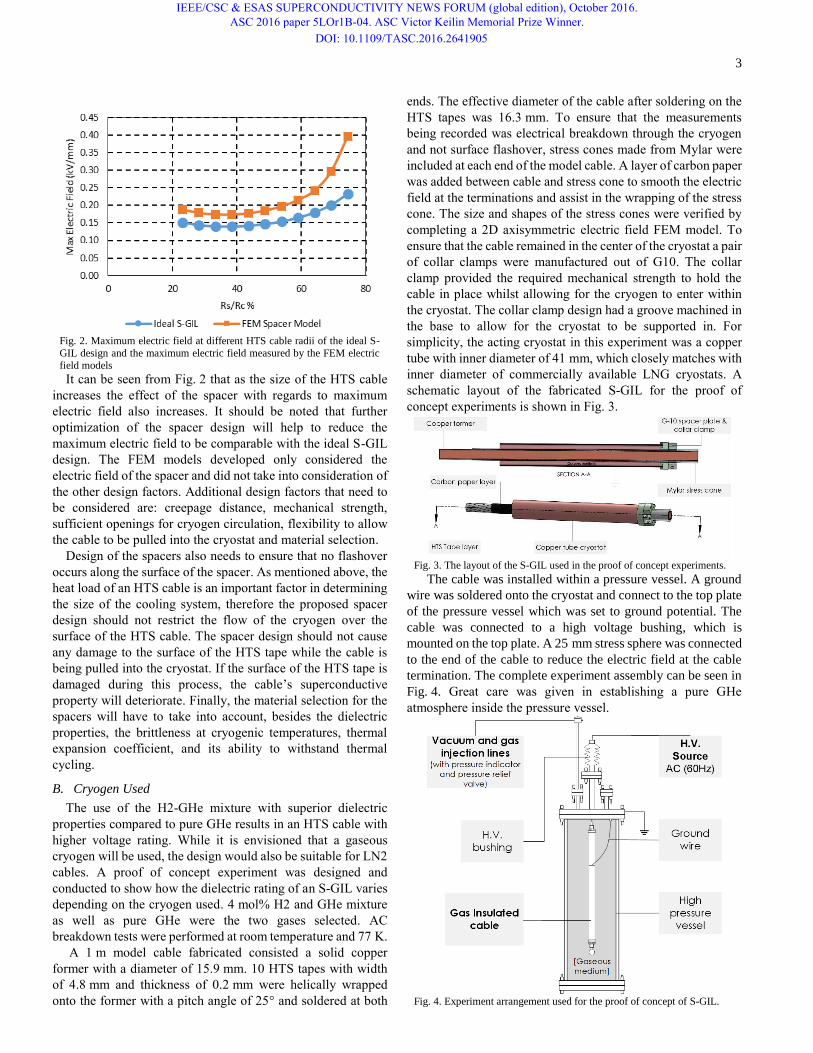
Fig. 2. Maximum electric field at different HTS cable radii of the ideal S-
GIL design and the maximum electric field measured by the FEM electric
field models It can be seen from Fig. 2 that as the size of the HTS cable
increases the effect of the spacer with regards to maximum
electric field also increases. It should be noted that further
optimization of the spacer design will help to reduce the
maximum electric field to be comparable with the ideal S-GIL
design. The FEM models developed only considered the
electric field of the spacer and did not take into consideration of
the other design factors. Additional design factors that need to
be considered are: creepage distance, mechanical strength,
sufficient openings for cryogen circulation, flexibility to allow
the cable to be pulled into the cryostat and material selection.
Design of the spacers also needs to ensure that no flashover
occurs along the surface of the spacer. As mentioned above, the
heat load of an HTS cable is an important factor in determining
the size of the cooling system, therefore the proposed spacer
design should not restrict the flow of the cryogen over the
surface of the HTS cable. The spacer design should not cause
any damage to the surface of the HTS tape while the cable is
being pulled into the cryostat. If the surface of the HTS tape is
damaged during this process, the cable’s superconductive
property will deteriorate. Finally, the material selection for the
spacers will have to take into account, besides the dielectric
properties, the brittleness at cryogenic temperatures, thermal
expansion coefficient, and its ability to withstand thermal
cycling.
B. Cryogen Used
The use of the H2-GHe mixture with superior dielectric
properties compared to pure GHe results in an HTS cable with
higher voltage rating. While it is envisioned that a gaseous
cryogen will be used, the design would also be suitable for LN2
cables. A proof of concept experiment was designed and
conducted to show how the dielectric rating of an S-GIL varies
depending on the cryogen used. 4 mol% H2 and GHe mixture
as well as pure GHe were the two gases selected. AC
breakdown tests were performed at room temperature and 77 K.
A 1 m model cable fabricated consisted a solid copper
former with a diameter of 15.9 mm. 10 HTS tapes with width
of 4.8 mm and thickness of 0.2 mm were helically wrapped
onto the former with a pitch angle of 25° and soldered at both
ends. The effective diameter of the cable after soldering on the
HTS tapes was 16.3 mm. To ensure that the measurements
being recorded was electrical breakdown through the cryogen
and not surface flashover, stress cones made from Mylar were
included at each end of the model cable. A layer of carbon paper
was added between cable and stress cone to smooth the electric
field at the terminations and assist in the wrapping of the stress
cone. The size and shapes of the stress cones were verified by
completing a 2D axisymmetric electric field FEM model. To
ensure that the cable remained in the center of the cryostat a pair
of collar clamps were manufactured out of G10. The collar
clamp provided the required mechanical strength to hold the
cable in place whilst allowing for the cryogen to enter within
the cryostat. The collar clamp design had a groove machined in
the base to allow for the cryostat to be supported in. For
simplicity, the acting cryostat in this experiment was a copper
tube with inner diameter of 41 mm, which closely matches with
inner diameter of commercially available LNG cryostats. A
schematic layout of the fabricated S-GIL for the proof of
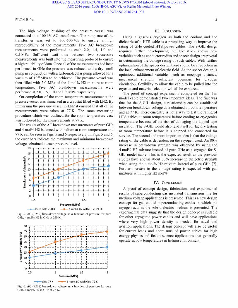
concept experiments is shown in Fig. 3.
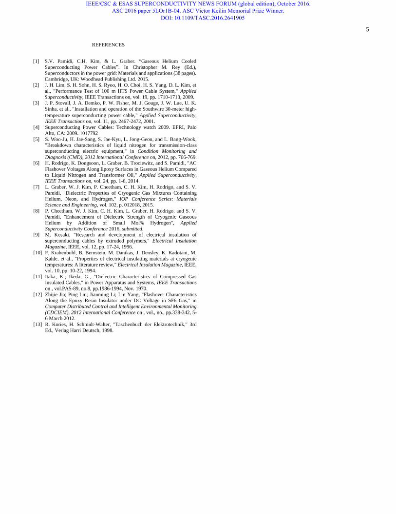
Fig. 3. The layout of the S-GIL used in the proof of concept experiments. The cable was installed within a pressure vessel. A ground
wire was soldered onto the cryostat and connect to the top plate
of the pressure vessel which was set to ground potential. The
cable was connected to a high voltage bushing, which is
mounted on the top plate. A 25 mm stress sphere was connected
to the end of the cable to reduce the electric field at the cable
termination. The complete experiment assembly can be seen in
Fig. 4. Great care was given in establishing a pure GHe
atmosphere inside the pressure vessel.
Fig. 4. Experiment arrangement used for the proof of concept of S-GIL.
IEEE/CSC & ESAS SUPERCONDUCTIVITY NEWS FORUM (global edition), October 2016. ASC 2016 paper 5LOr1B-04. ASC Victor Keilin Memorial Prize Winner.
DOI: 10.1109/TASC.2016.2641905
5LOr1B-04 4
The high voltage bushing of the pressure vessel was
connected to a 100 kV AC transformer. The ramp rate of the
transformer was set to 300-500 V/s to ensure a high
reproducibility of the measurements. Five AC breakdown
measurements were performed at each 2.0, 1.5, 1.0 and
0.5 MPa. Sufficient wait time between two successive
measurements was built into the measuring protocol to ensure
a high reliability of data. Once all of the measurements had been
performed in GHe the pressure was reduced and a dry scroll
pump in conjunction with a turbomolecular pump allowed for a
vacuum of 10-8 MPa to be achieved. The pressure vessel was
then filled with 2.0 MPa of the 4 mol% H2 mixture at room
temperature. Five AC breakdown measurements were
performed at 2.0, 1.5, 1.0 and 0.5 MPa respectively.
On completion of the room temperature measurements the
pressure vessel was immersed in a cryostat filled with LN2. By
immersing the pressure vessel in LN2 it ensured that all of the
measurements were taken at 77 K. The same measuring
procedure which was outlined for the room temperature case
was followed for the measurements at 77 K.
The results of the AC breakdown measurements of pure GHe
and 4 mol% H2 balanced with helium at room temperature and
77 K can be seen in Figs. 5 and 6 respectively. In Figs. 5 and 6,
the error bars indicate the maximum and minimum breakdown
voltages obtained at each pressure level.
Fig. 5. AC (RMS) breakdown voltage as a function of pressure for pure GHe, 4 mol% H2 in GHe at 290 K.
Fig. 6. AC (RMS) breakdown voltage as a function of pressure for pure GHe, 4 mol% H2 in GHe at 77 K.
III. DISCUSSION
Using a gaseous cryogen as both the coolant and the
dielectric of a HTS cable is a promising way to improve the
rating of GHe cooled HTS power cables. The S-GIL design
requires further development, but the study shows how
variables such as conductor radius and spacer design are pivotal
in determining the voltage rating of such cables. With further
optimization of the spacer design there should be a reduction in
the local enhancement of electric field. As the spacer design is
optimized additional variables such as creepage distance,
mechanical strength, sufficient openings for cryogen
circulation, flexibility to allow the cable to be pulled into the
cryostat and material selection will all be explored.
The proof of concept experiments completed on the 1 m
model cable demonstrated two important ideas. The first was
that for the S-GIL design, a relationship can be established
between breakdown voltage data obtained at room temperature
and at 77 K. There currently is not a way to test the rating of
HTS cables at room temperature before cooling to cryogenics
temperature because of the risk of damaging the lapped tape
insulation. The S-GIL would also lend itself for factory testing
at room temperature before it is shipped and connected for
service. The second and more important idea is that the voltage
rating of the cable is dependent on the cryogen used. An 80%
increase in breakdown strength was observed by using the
4 mol% H2 mixture instead of pure GHe as a cryogen for S-
GIL model cable. This is the expected result as the previous
studies have shown about 80% increase in dielectric strength
when using the 4 mol% H2 mixture instead of pure GHe [7].
Further increase in the voltage rating is expected with gas
mixtures with higher H2 mol%.
IV. CONCLUSION
A proof of concept design, fabrication, and experimental
results of superconducting gas insulated transmission line for
medium voltage applications is presented. This is a new design
concept for gas cooled superconducting cables in which the
cryogen acts as the sole dielectric medium is presented. The
experimental data suggests that the design concept is suitable
for other cryogenic power cables and will have applications
where very high power density is needed for naval and
aviation applications. The design concept will also be useful
for current leads and short runs of power cables for high
energy physics and fusion science applications that generally
operate at low temperatures in helium environment.
IEEE/CSC & ESAS SUPERCONDUCTIVITY NEWS FORUM (global edition), October 2016. ASC 2016 paper 5LOr1B-04. ASC Victor Keilin Memorial Prize Winner.
DOI: 10.1109/TASC.2016.2641905
5
temperature superconducting power cable," Applied Superconductivity,
IEEE Transactions on, vol. 11, pp. 2467-2472, 2001. [4] Superconducting Power Cables: Technology watch 2009. EPRI, Palo
Alto, CA: 2009. 1017792
[5] S. Woo-Ju, H. Jae-Sang, S. Jae-Kyu, L. Jong-Geon, and L. Bang-Wook,"Breakdown characteristics of liquid nitrogen for transmission-class
superconducting electric equipment," in Condition Monitoring and
Diagnosis (CMD), 2012 International Conference on, 2012, pp. 766-769. [6] H. Rodrigo, K. Dongsoon, L. Graber, B. Trociewitz, and S. Pamidi, "AC
Flashover Voltages Along Epoxy Surfaces in Gaseous Helium Compared
to Liquid Nitrogen and Transformer Oil," Applied Superconductivity, IEEE Transactions on, vol. 24, pp. 1-6, 2014.
[7] L. Graber, W. J. Kim, P. Cheetham, C. H. Kim, H. Rodrigo, and S. V.
Pamidi, "Dielectric Properties of Cryogenic Gas Mixtures Containing Helium, Neon, and Hydrogen," IOP Conference Series: Materials
Science and Engineering, vol. 102, p. 012018, 2015.
[8] P. Cheetham, W. J. Kim, C. H. Kim, L. Graber, H. Rodrigo, and S. V. Pamidi, "Enhancement of Dielectric Strength of Cryogenic Gaseous
Helium by Addition of Small Mol% Hydrogen", Applied
Superconductivity Conference 2016, submitted.[9] M. Kosaki, "Research and development of electrical insulation of
superconducting cables by extruded polymers," Electrical Insulation
Magazine, IEEE, vol. 12, pp. 17-24, 1996. [10] F. Krahenbuhl, B. Bernstein, M. Danikas, J. Densley, K. Kadotani, M.
Kahle, et al., "Properties of electrical insulating materials at cryogenic
temperatures: A literature review," Electrical Insulation Magazine, IEEE,vol. 10, pp. 10-22, 1994.
[11] Itaka, K.; Ikeda, G., "Dielectric Characteristics of Compressed GasInsulated Cables," in Power Apparatus and Systems, IEEE Transactions
on , vol.PAS-89, no.8, pp.1986-1994, Nov. 1970.
[12] Zhijie Jia; Ping Liu; Jianming Li; Lin Yang, "Flashover Characteristics Along the Epoxy Resin Insulator under DC Voltage in SF6 Gas," in
Computer Distributed Control and Intelligent Environmental Monitoring
(CDCIEM), 2012 International Conference on , vol., no., pp.338-342, 5-6 March 2012.
[13] R. Kories, H. Schmidt-Walter, "Taschenbuch der Elektrotechnik," 3rd
Ed., Verlag Harri Deutsch, 1998.
IEEE/CSC & ESAS SUPERCONDUCTIVITY NEWS FORUM (global edition), October 2016. ASC 2016 paper 5LOr1B-04. ASC Victor Keilin Memorial Prize Winner.
DOI: 10.1109/TASC.2016.2641905
[1] S.V. Pamidi, C.H. Kim, & L. Graber. “Gaseous Helium Cooled
Superconducting Power Cables”. In Christopher M. Rey (Ed.), Superconductors in the power grid: Materials and applications (38 pages).
Cambridge, UK: Woodhead Publishing Ltd. 2015. [2] J. H. Lim, S. H. Sohn, H. S. Ryoo, H. O. Choi, H. S. Yang, D. L. Kim, et
al., "Performance Test of 100 m HTS Power Cable System," Applied
Superconductivity, IEEE Transactions on, vol. 19, pp. 1710-1713, 2009. [3] J. P. Stovall, J. A. Demko, P. W. Fisher, M. J. Gouge, J. W. Lue, U. K.
Sinha, et al., "Installation and operation of the Southwire 30-meter high-
REFERENCES