Embed Size (px)
Citation preview
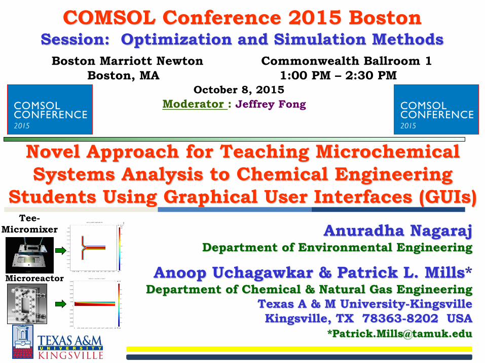
Novel Approach for Teaching Microchemical
Systems Analysis to Chemical Engineering
Students Using Graphical User Interfaces (GUIs)
Anuradha NagarajDepartment of Environmental Engineering
Anoop Uchagawkar & Patrick L. Mills*Department of Chemical & Natural Gas Engineering
Texas A & M University-Kingsville
Kingsville, TX 78363-8202 USA
COMSOL Conference 2015 BostonSession: Optimization and Simulation Methods
Boston Marriott Newton Commonwealth Ballroom 1
Boston, MA 1:00 PM – 2:30 PMOctober 8, 2015
Moderator : Jeffrey Fong
Tee-
Micromixer
Microreactor
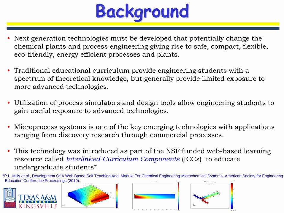
Background
• Next generation technologies must be developed that potentially change the
chemical plants and process engineering giving rise to safe, compact, flexible,
eco-friendly, energy efficient processes and plants.
• Traditional educational curriculum provide engineering students with a
spectrum of theoretical knowledge, but generally provide limited exposure to
more advanced technologies.
• Utilization of process simulators and design tools allow engineering students to
gain useful exposure to advanced technologies.
• Microprocess systems is one of the key emerging technologies with applications
ranging from discovery research through commercial processes.
• This technology was introduced as part of the NSF funded web-based learning
resource called Interlinked Curriculum Components (ICCs) to educate
undergraduate students*. *P.L. Mills et al., Development Of A Web Based Self Teaching And Module For Chemical Engineering Microchemical Systems, American Society for Engineering
Education Conference Proceedings (2010).
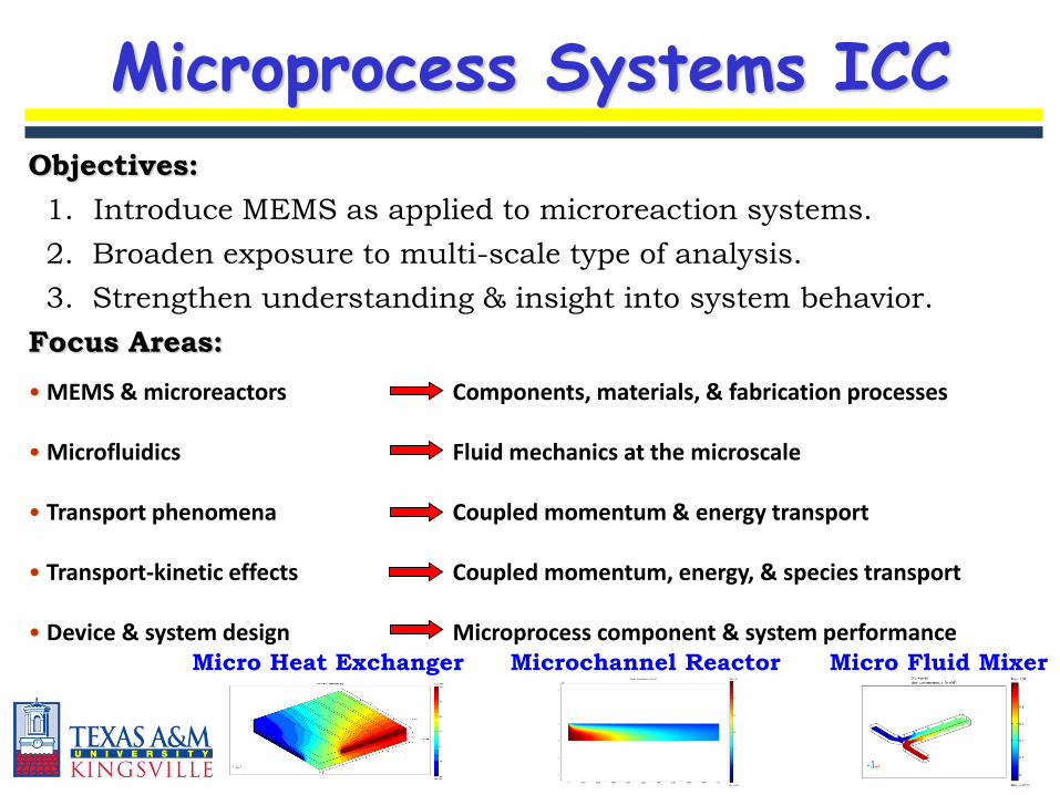
Microprocess Systems ICC
• MEMS & microreactors Components, materials, & fabrication processes
• Microfluidics Fluid mechanics at the microscale
• Transport phenomena Coupled momentum & energy transport
• Transport-kinetic effects Coupled momentum, energy, & species transport
• Device & system design Microprocess component & system performance
Objectives:
1. Introduce MEMS as applied to microreaction systems.
2. Broaden exposure to multi-scale type of analysis.
3. Strengthen understanding & insight into system behavior.
Focus Areas:
Micro Heat Exchanger Microchannel Reactor Micro Fluid Mixer
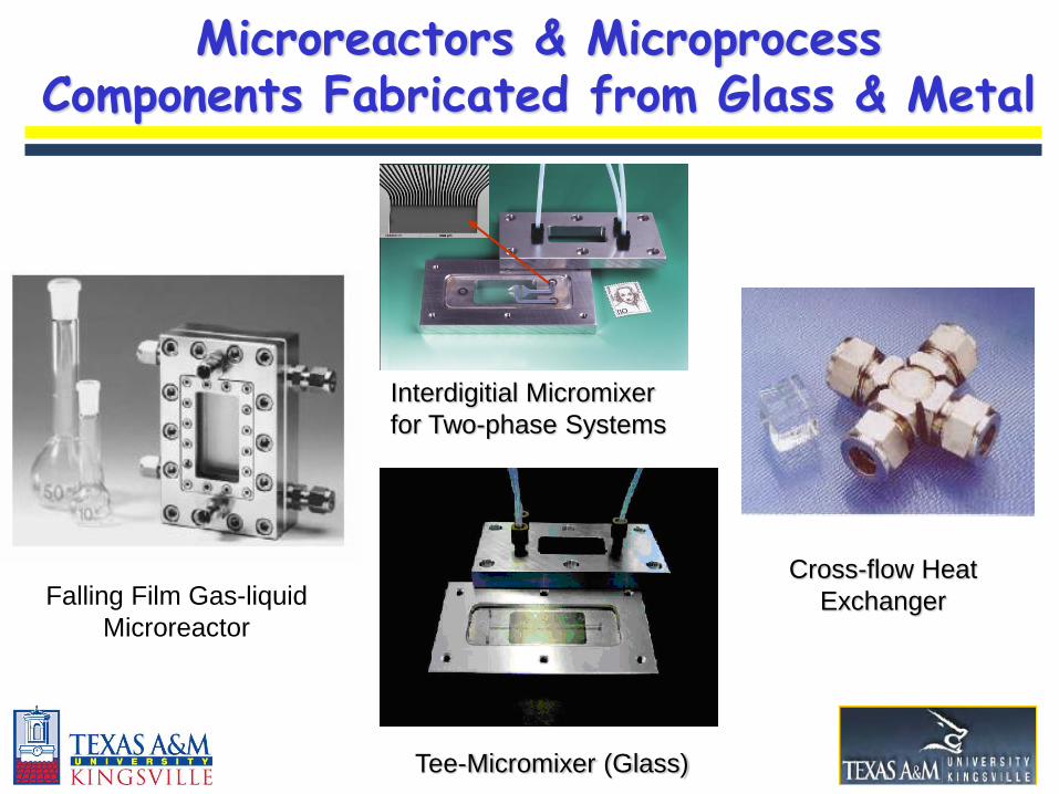
Tee-Micromixer (Glass)
Falling Film Gas-liquid
Microreactor
Cross-flow Heat
Exchanger
Interdigitial Micromixer
for Two-phase Systems
Microreactors & MicroprocessComponents Fabricated from Glass & Metal
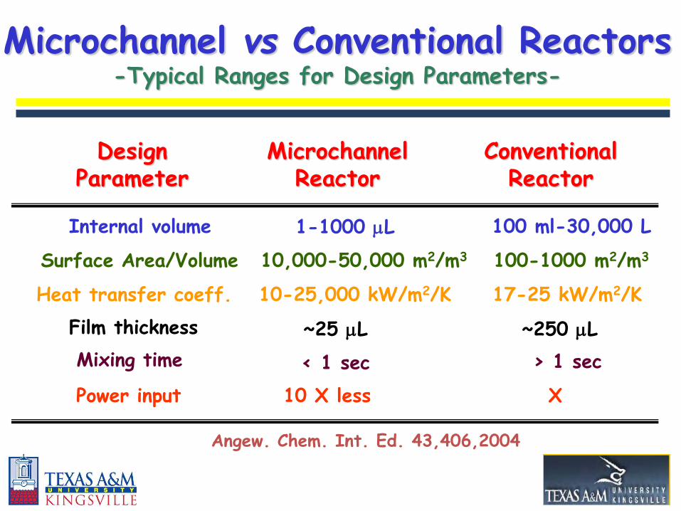
Microchannel vs Conventional Reactors-Typical Ranges for Design Parameters-
Internal volume 1-1000 L 100 ml-30,000 L
Surface Area/Volume 10,000-50,000 m2/m3 100-1000 m2/m3
Heat transfer coeff. 10-25,000 kW/m2/K
Film thickness ~25 L ~250 L
Mixing time < 1 sec > 1 sec
17-25 kW/m2/K
Power input 10 X less
MicrochannelReactor
ConventionalReactor
DesignParameter
X
Angew. Chem. Int. Ed. 43,406,2004
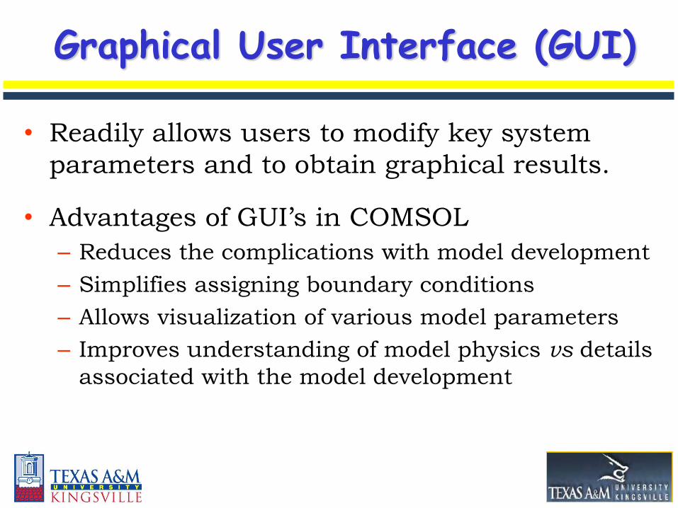
Graphical User Interface (GUI)
• Readily allows users to modify key system
parameters and to obtain graphical results.
• Advantages of GUI’s in COMSOL
– Reduces the complications with model development
– Simplifies assigning boundary conditions
– Allows visualization of various model parameters
– Improves understanding of model physics vs details
associated with the model development
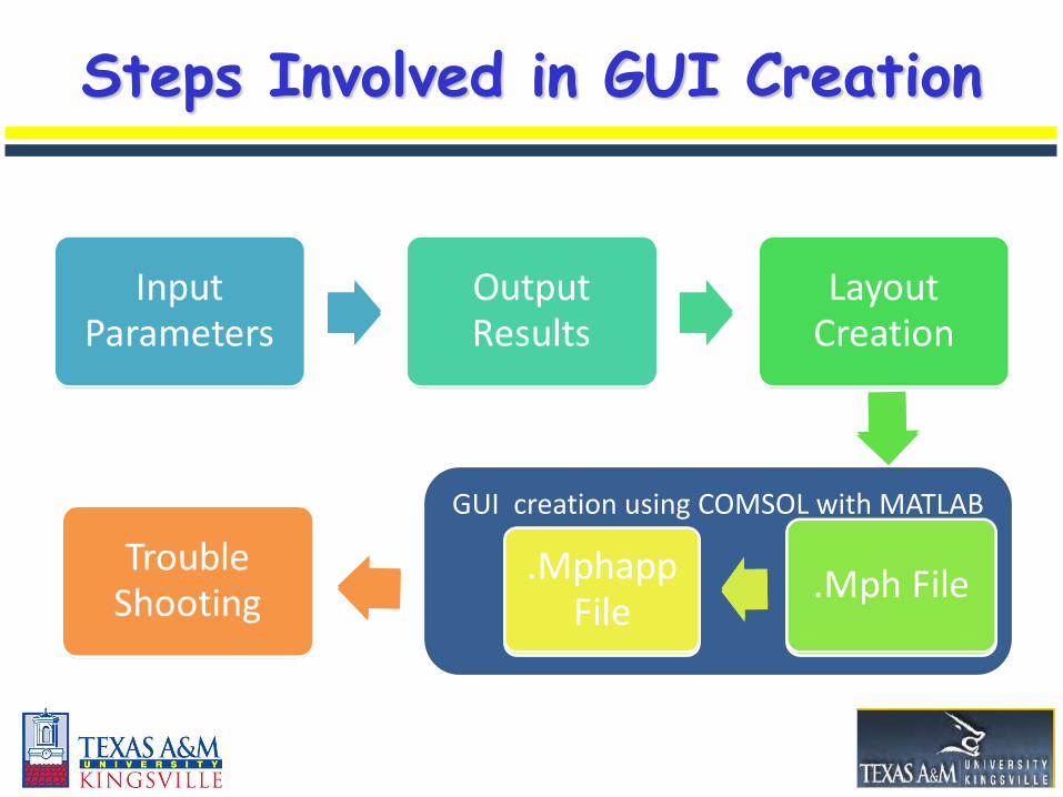
GUI creation using COMSOL with MATLAB
Input Parameters
Output Results
Layout Creation
.fig File .m FileTrouble
Shooting
Steps Involved in GUI Creation
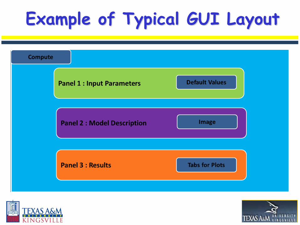
Example of Typical GUI Layout
Panel 1 : Geometry or Solute Properties
Panel 2 : Fluid Properties or Carrier Fluid Properties
Panel 3 : Boundary Conditions
Solve
Select Graph
Plot Graph
Default Values
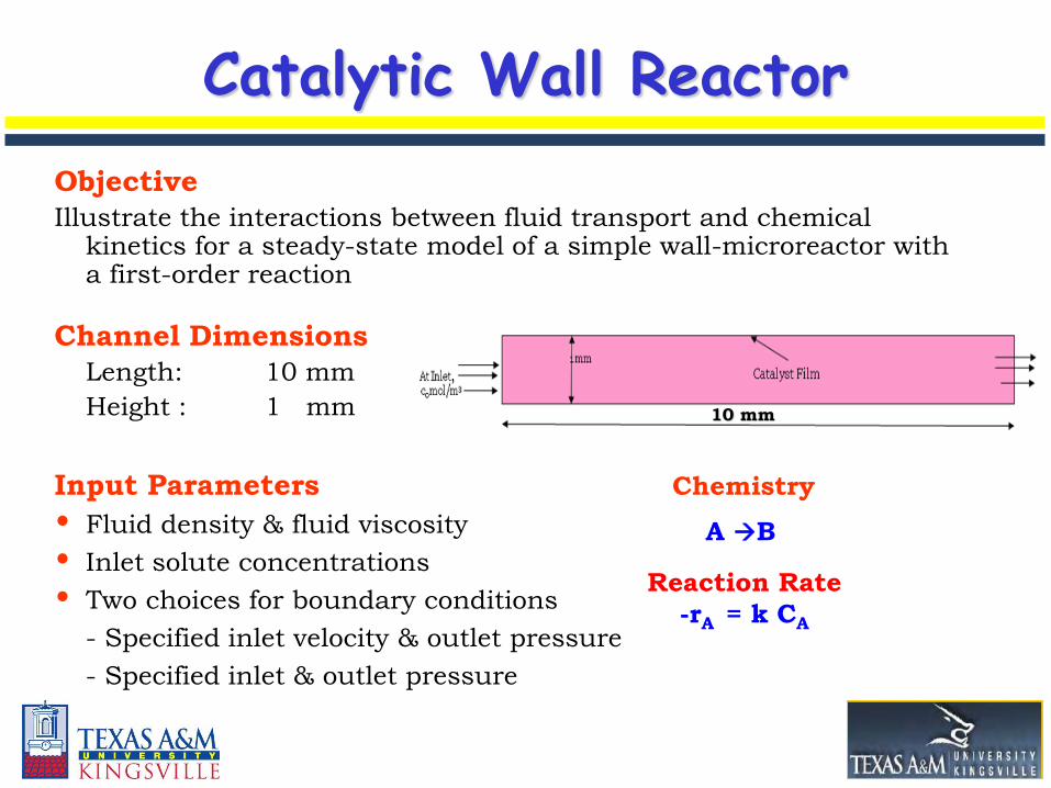
Catalytic Wall Reactor
Objective
Illustrate the interactions between fluid transport and chemical kinetics for a steady-state model of a simple wall-microreactor with a first-order reaction
Channel Dimensions
Length: 10 mm
Height : 1 mm
Input Parameters
• Fluid density & fluid viscosity
• Inlet solute concentrations
• Two choices for boundary conditions
- Specified inlet velocity & outlet pressure
- Specified inlet & outlet pressure
10 mm
A B
Chemistry
Reaction Rate
-rA = k CA
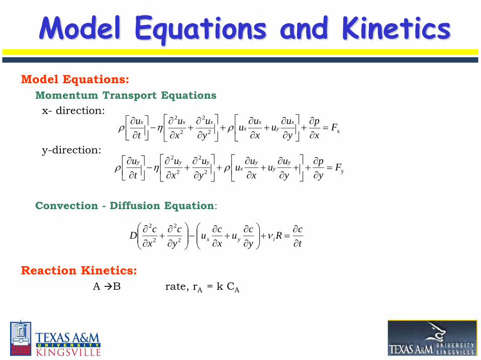
Model Equations:
Momentum Transport Equations
x- direction:
y-direction:
Convection - Diffusion Equation:
Reaction Kinetics:
A B rate, rA = k CA
x2
2
2
2
Fx
p
y
uu
x
uu
y
u
x
u
t
u xy
xx
xxx
y2
2
2
2
Fy
p
y
uu
x
uu
y
u
x
u
t
u yy
yx
yyy
t
cR
y
cu
x
cu
y
c
x
cD iyx
2
2
2
2
Model Equations and Kinetics
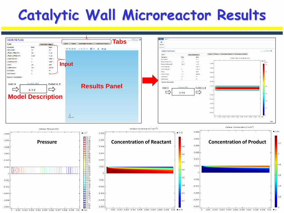
Catalytic Wall Microreactor Results
Surface Concentration Surface Velocity ProfilesPressure
Results Panel
Tabs
Input
Model Description
Concentration of Reactant Concentration of Product
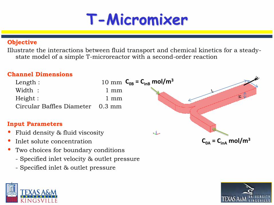
T-MicromixerObjective
Illustrate the interactions between fluid transport and chemical kinetics for a steady-state model of a simple T-microreactor with a second-order reaction
Channel Dimensions
Length : 10 mm
Width : 1 mm
Height : 1 mm
Circular Baffles Diameter 0.3 mm
Input Parameters
• Fluid density & fluid viscosity
• Inlet solute concentration
• Two choices for boundary conditions
- Specified inlet velocity & outlet pressure
- Specified inlet & outlet pressure
C0B = CinB mol/m3
C0A = CinA mol/m3
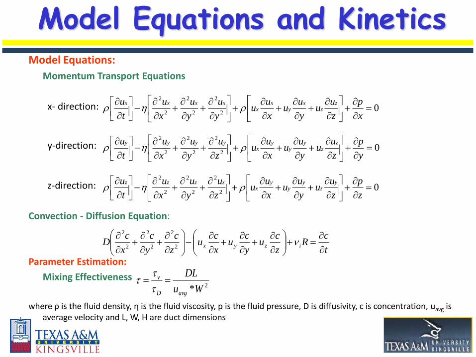
Model Equations:
Momentum Transport Equations
x- direction:
y-direction:
z-direction:
Convection - Diffusion Equation:
Parameter Estimation:
Mixing Effectiveness
where ρ is the fluid density, η is the fluid viscosity, p is the fluid pressure, D is diffusivity, c is concentration, uavg is average velocity and L, W, H are duct dimensions
02
2
2
2
2
2
x
p
z
uu
y
uu
x
uu
y
u
y
u
x
u
t
u zz
xy
xx
xxxx
02
2
2
2
2
2
y
p
z
uu
y
uu
x
uu
z
u
y
u
x
u
t
u zz
yy
yx
yyyy
02
2
2
2
2
2
z
p
z
uu
y
uu
x
uu
z
u
y
u
x
u
t
u yz
yy
yx
zzzz
t
cR
z
cu
y
cu
x
cu
z
c
y
c
x
cD izyx
2
2
2
2
2
2
Model Equations and Kinetics
2*Wu
DL
avgD
v
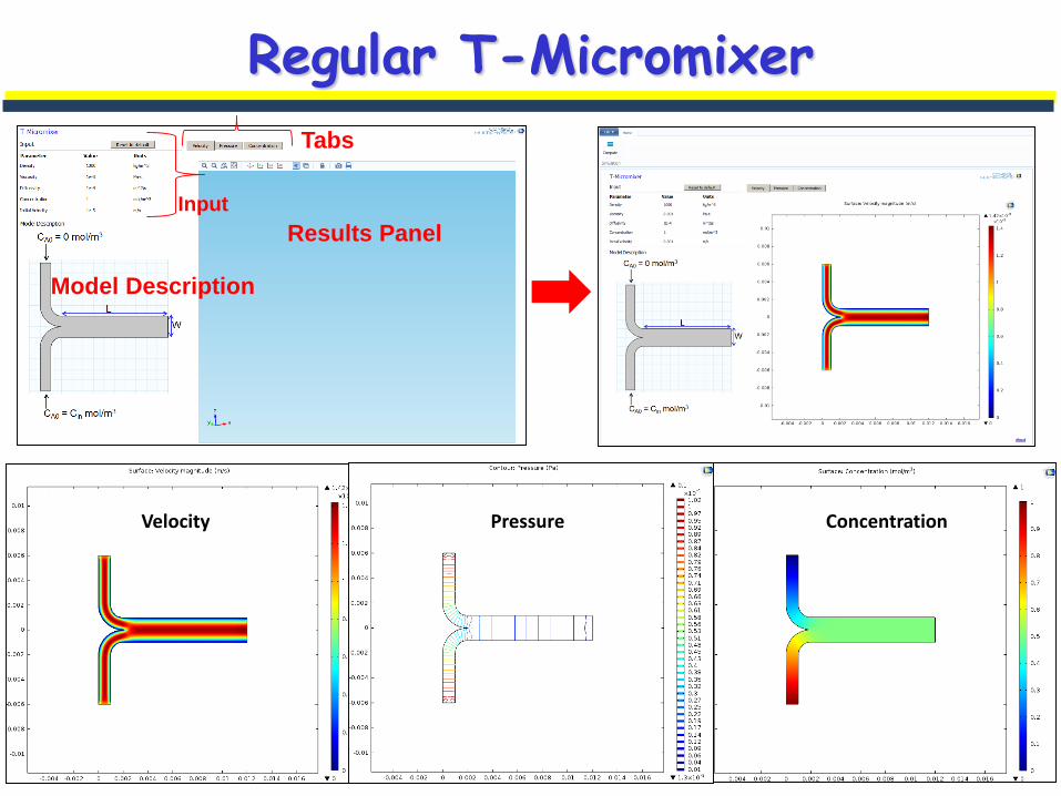
Regular T-Micromixer
Concentration Mixing EffectivenessVelocity
Velocity
Results Panel
Tabs
Input
Model Description
Pressure Concentration
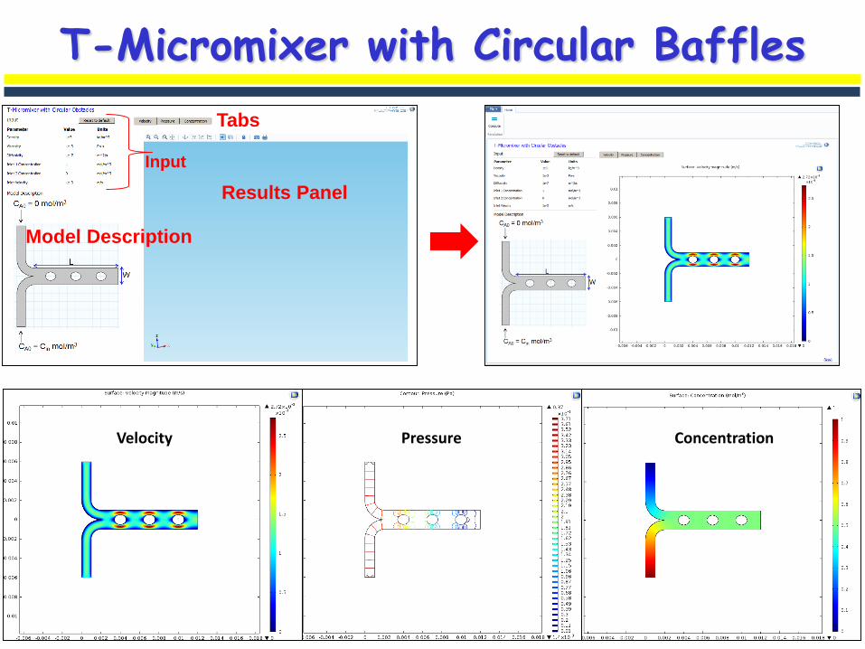
T-Micromixer with Circular Baffles
Concentration Mixing EffectivenessVelocity
Velocity
Results Panel
Tabs
Input
Model Description
Pressure Concentration
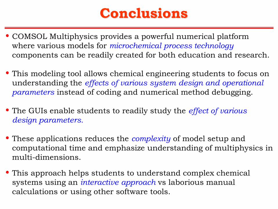
Conclusions
• COMSOL Multiphysics provides a powerful numerical platform
where various models for microchemical process technology
components can be readily created for both education and research.
• This modeling tool allows chemical engineering students to focus on
understanding the effects of various system design and operational
parameters instead of coding and numerical method debugging.
• The GUIs enable students to readily study the effect of various
design parameters.
• These applications reduces the complexity of model setup and
computational time and emphasize understanding of multiphysics in
multi-dimensions.
• This approach helps students to understand complex chemical
systems using an interactive approach vs laborious manual
calculations or using other software tools.

Additional SupportingDocumentation
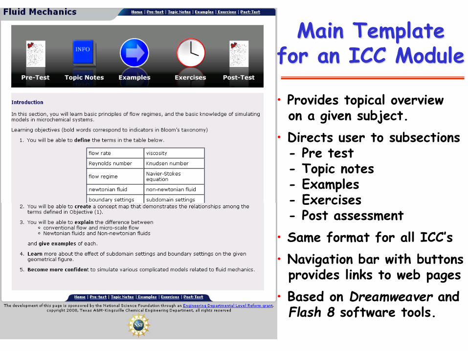
Main Templatefor an ICC Module
• Provides topical overviewon a given subject.
• Directs user to subsections- Pre test- Topic notes- Examples- Exercises- Post assessment
• Same format for all ICC’s
• Navigation bar with buttonsprovides links to web pages
• Based on Dreamweaver andFlash 8 software tools.
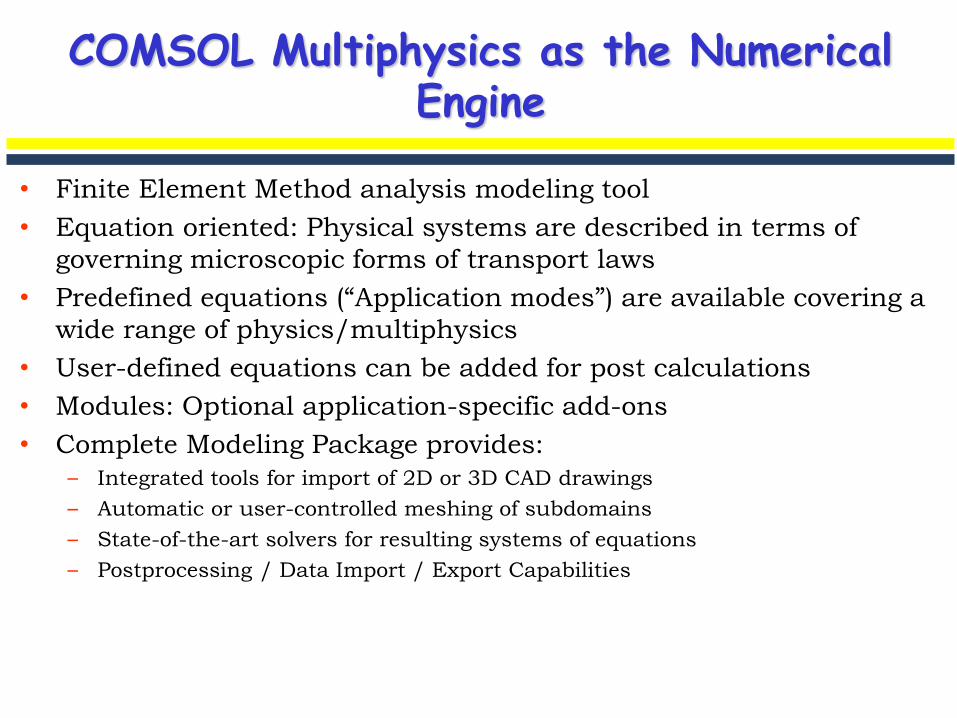
COMSOL Multiphysics as the Numerical Engine
• Finite Element Method analysis modeling tool
• Equation oriented: Physical systems are described in terms of
governing microscopic forms of transport laws
• Predefined equations (“Application modes”) are available covering a
wide range of physics/multiphysics
• User-defined equations can be added for post calculations
• Modules: Optional application-specific add-ons
• Complete Modeling Package provides:
– Integrated tools for import of 2D or 3D CAD drawings
– Automatic or user-controlled meshing of subdomains
– State-of-the-art solvers for resulting systems of equations
– Postprocessing / Data Import / Export Capabilities
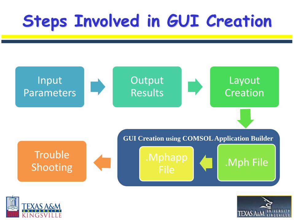
GUI creation using COMSOL with MATLAB
Input Parameters
Output Results
Layout Creation
.Mph File.MphappFile
Trouble Shooting
Steps Involved in GUI Creation
GUI Creation using COMSOL Application Builder
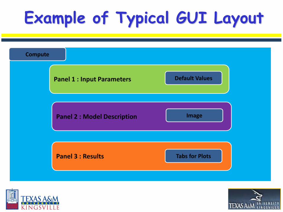
Example of Typical GUI Layout
Panel 1 : Input Parameters
Panel 2 : Model Description
Panel 3 : Results
Compute
Image
Tabs for Plots
Default Values

Pressure
Catalytic Wall Microreactor Results
Results Panel
Tabs
Input
Model Description
Concentration of Reactant Concentration of Product
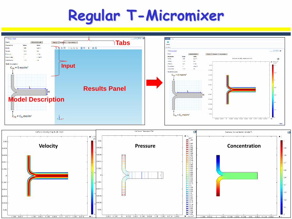
Regular T-Micromixer
Velocity
Results Panel
Tabs
Input
Model Description
Pressure Concentration
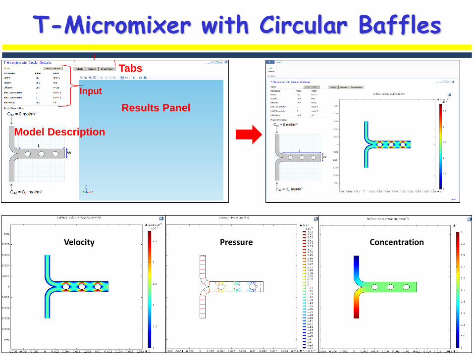
T-Micromixer with Circular Baffles
Velocity
Results Panel
Tabs
Input
Model Description
Pressure Concentration
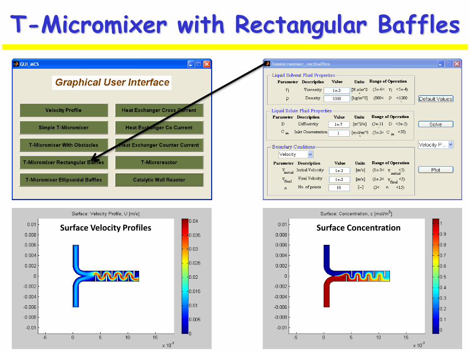
T-Micromixer with Rectangular Baffles
Surface Velocity Profiles Surface Concentration