Embed Size (px)
DESCRIPTION
nova.
Citation preview

P/N 20-08808-00C 1
The TOTAL ECLIPSE Controller is an integral part of the TOTAL ECLIPSE Chemical Management System, which also includes: • The Machine Interface – Accepts washer signals and converts them to safe, low-voltage inputs.• The Pump Module – Provides product transfer to the wash machine. The TOTAL ECLIPSE Controller is compatible with
any Nova Controls’ modular pumpstand. including the Eclipse, Orion or any of the Large Laundry dispensers. • The Flush Manifold (optional) – Available for water flush chemical transfer applications.
Designed for maximum versatility in OPL or large laundry machines, the TOTAL ECLIPSE Controller’s selectable OperatingModes allow the system to work with trigger signals from fully-programmable washers or with manually triggered signals (or cycletime extenders) from non-programmable, fixed-time washers. The Controller’s easy-to-understand, plain-text LCD display (availablein a variety of languages), make operator training simple. Installation time and cost is significantly reduced with the computer basedFormula Editor program, allowing an off-site technician to create sets of up to 20 industry-specific, efficient and cost-effectiveformulas that are loaded onto a controller with a customer-supplied USB flash drive (2 GB or smaller). Summary Reports can besaved to the same USB flash drive, providing usage and programming information to effectively analyze and manage each machine.
Components Supplied
How to Use the TOTAL ECLIPSE Quick Start GuideUse this Quick Start Guide if you are already familiarwith installing and using dispensing systems. Pleaserefer to the TOTAL ECLIPSE Reference Manual fordetailed instructions, including information on theoptional Relay, Event, Occurrence and GroupOperating Modes. Refer also to the Installation andOperations manual that is included with yourpumpstand or upgrade kit for additional instructions. IMPORTANT NOTE: Quick Start instructionsassume that Formula/Setup files will be loaded via a USBflash drive, which may override the following factorydefault settings: Standard Operation; Eclipse Flush P.I.; Flush Time–0 sec.; Cycle Time–90 min.; Signal Filter Time–2 sec.; User Prime– Disabled;Bleach Defeat–Off; Units of Measure = SAE. Default Passwords are Installer = 01234; Manager = 0123. It is recommended that default passwordsare changed via the controller’s keypad (and noted) after installation and system setup are complete. To change formulas, settings or passwordsusing controller keys, or to add a machine or company name, see the Guide to Keypad and Menus (p. 5) and Initial Setup on Installer Menus (p. 6).
NOVA CONTROLS
A SystemsCompany
L E A D I N G T H E W A Y
TOTAL ECLIPSE Quick Start Guidefor the TOTAL ECLIPSE CHEMICAL MANAGEMENT SYSTEM
TOTAL ECLIPSE Controller(P/N 01-08500-00, Grey/Teal)(P/N 01-08900-00, Black/Red)
Wall Mount Bracket, Kit (P/N 13-08462-00, Grey) (P/N 13-08916-00, Black)
Quick Start Guide(P/N 20-08808-00)
DOWNLOAD from the Nova Controls website (http://www.novacontrols.com):• Formula Editor Software – for Windows 2000/XP/Vista, Linux & Mac OS 10.4
(Minimum requirements: Java JRE 1.5 or higher [90 MB disc space]; 1024 x 768 screen resolution; 128 MB RAM; 10 MBdisc space; USB 2.0 and a USB flash drive [2GB or smaller, FAT32 format] for data transfer to TOTAL ECLIPSE controller
• Additional Language Files –Two Types (for Formula Editor Software and for TOTAL ECLIPSE Controller Menus )• TOTAL ECLIPSE Complete Reference Manual – at www.novacontrols.com/instructions.htm (P/N 20-08490-00)
TOTAL ECLIPSE Controller Specifications Size 5.25" W x 4.0" H x 2.5" D ( 13.4 cm W x 10.2 cm H x 6.4 cm D)Weight 0.65 lb. (0.30 kg)Power Rating SELV — Power source is pumpstandData Input Field Size 15 characters maximum input for custom namesPump Capacity 99.99 oz. (2999 ml.) 8 pump (with 3 amount settings per pump) maximumEnvironmental IP Rating – 44 Pollution Category – 2 Installation Category – IITemperature 10° to 49° C (50° to 120° F) maximumHumidity 95% relative humidity, maximumIndoor Installation Approved for indoor use only. Must not be installed outdoors.Altitude Install at or below 6,500 ft. (2000 m) maximum
Specifications subject to change without notice.
Copyright 2008 Nova Controls, Inc.
2 P/N 20-08808-00C
Installation
Step 1. Install the Machine Interface (MI)
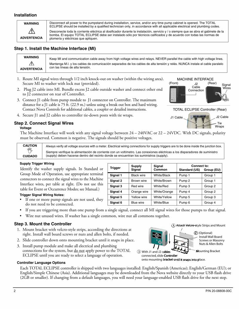
1. Route MI signal wires through 1/2 inch knock-out on washer (within the wiring area). Secure MI to washer with lock nut (provided).
2. Plug J2 cable into MI. Bundle excess J2 cable outside washer and connect other end to J2 connector on rear of Controller.
3. Connect J1 cable from pump module to J1 connector on Controller. The maximum distance for a J1 cable is 75 ft. (22.9 m.) unless using a break out box and hard wiring. Contact Nova Controls for additional cables, a coupler or detailed instructions.
4. Secure J1 and J2 cables to controller tie-down posts with tie wraps.
Step 2. Connect Signal WiresVoltage
The Machine Interface will work with any signal voltage between 24 – 240VAC or 22 – 24VDC. With DC signals, polarity must be observed. Common is negative. The signals should be positive voltages.
Supply Trigger Wiring
Identify the washer supply signals. In Standard orGroup Mode of Operation, use appropriate terminalconnectors to connect the signal wires to the MachineInterface wires, per table at right. (Do not use thistable for Event or Occurrence Modes; see Manual.)Trigger Signal Wiring Notes: • If one or more pump signals are not used, they
do not need to be connected. • If you are triggering more than one pump from a single signal, connect all MI signal wires for those pumps to that signal. • Wire nut unused wires. If washer has a single common, wire nut all commons together.
Step 3. Mount the Controller1. Mount bracket with velcro-style strips, according the directions at
right. Install wall board screws or nuts and allen bolts, if needed.2. Slide controller down onto mounting bracket until it snaps in place.3. Install pump module and make all electrical and plumbing
connections for the system, but do not apply power to the TOTAL ECLIPSE until you are ready to select a language of operation.
Controller Language Options
Each TOTAL ECLIPSE controller is shipped with two languages installed: English/Spanish (Americas); English/German (EU); or English/Simple Chinese (Asia). Additional languages may be downloaded from the Nova website directly to your USB flash drive (2GB or smaller). If changing from a default languages, you will need your language-enabled USB flash drive for the next step.
WARNING
ADVERTENCIA
Disconnect all power to the pumpstand during installation, service, and/or any time pump cabinet is opened. The TOTAL ECLIPSE should be installed by a qualified technician only, in accordance with all applicable electrical and plumbing codes.
Desconecte toda la corriente eléctrica al dosificador durante la instalación, servicio y / o siempre que se abra el gabinete de la bomba. El equipo TOTAL ECLIPSE debe ser instalado sólo por técnicos calificados y de acuerdo con todas las normas de plomería y eléctricas que apliquen.
WARNING
ADVERTENCIA
Keep MI and communication cable away from high voltage wires and relays. NEVER parallel the cable with high voltage lines.
Mantenga M.I. y los cables de comunicación separados de los cables de alta tensión y relés. NUNCA instale el cable paralelo con las líneas de alta tensión.
CAUTION
CUIDADO
Always verify all voltage sources with a meter. Electrical wiring connections for supply triggers are to be done inside the junction box.
Siempre verifique la alimentación de corriente con un voltímetro. Las conexiones eléctricas a los disparadores de suministro (supply) deben hacerse dentro del recinto donde se encuentran los suministros (supply).
TOTAL ECLIPSE Controller (Rear)
J1 Cable J2 Cable
TieWraps
MACHINE INTERFACE (Front) (Rear) Signal
WiresJ2
CableConnection
Trigger Supply Signal
Signal Common
Connect to: Standard (US) Group (EU)
Signal 1 Black wire White/Black Pump 1 Group 1
Signal 2 Brown wire White/Brown Pump 2 Group 1
Signal 3 Red wire White/Red Pump 3 Group 2
Signal 4 Orange wire White/Orange Pump 4 Group 2
Signal 5 Yellow wire White/Yellow Pump 5 Group 3
Signal 6 Blue wire White/Blue Pump 6 Group 4
Mounting Bracket3 With J1 and J2 cables connected, slide Controller onto mounting bracket until it snaps into place.
1 Attach Velcro-style Strips and Mount
Install Wall Board Screws or Masonry Nuts & Allen Bolts
2 (Optional)
P/N 20-08808-00C 3
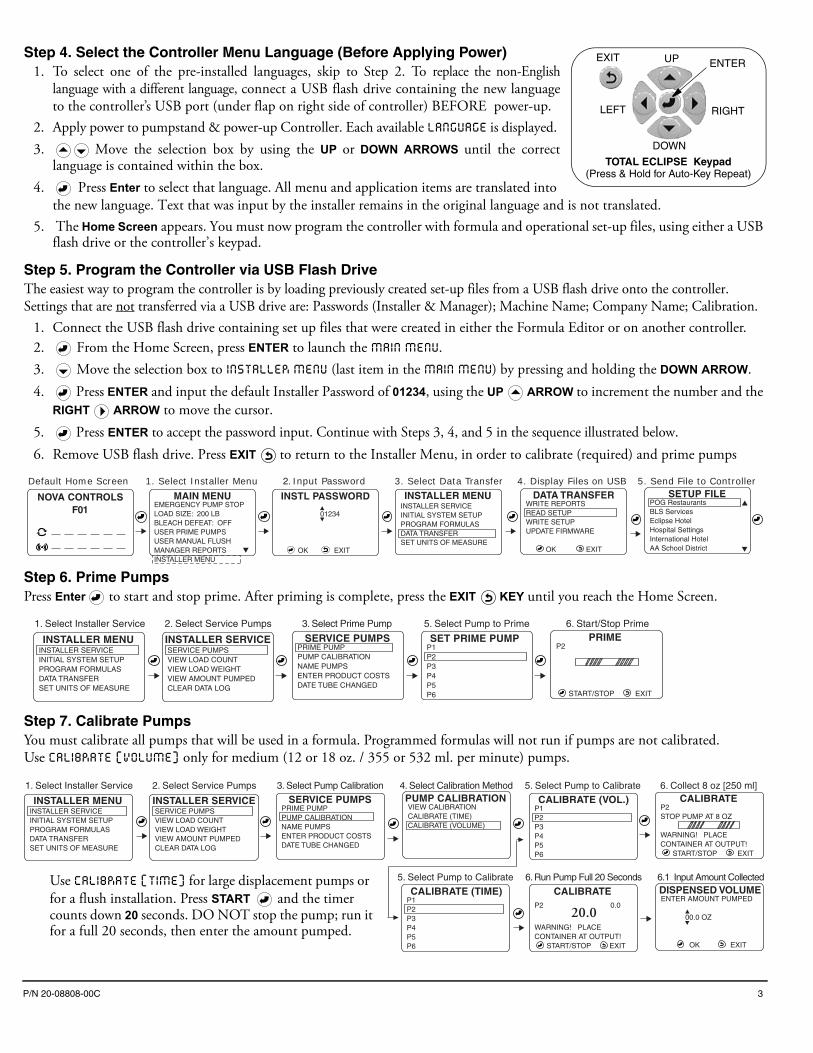
Step 4. Select the Controller Menu Language (Before Applying Power)1. To select one of the pre-installed languages, skip to Step 2. To replace the non-English
language with a different language, connect a USB flash drive containing the new languageto the controller’s USB port (under flap on right side of controller) BEFORE power-up.
2. Apply power to pumpstand & power-up Controller. Each available LANGUAGE is displayed. 3. Move the selection box by using the UP or DOWN ARROWS until the correct
language is contained within the box. 4. Press Enter to select that language. All menu and application items are translated into
the new language. Text that was input by the installer remains in the original language and is not translated.5. The Home Screen appears. You must now program the controller with formula and operational set-up files, using either a USB
flash drive or the controller’s keypad.
Step 5. Program the Controller via USB Flash DriveThe easiest way to program the controller is by loading previously created set-up files from a USB flash drive onto the controller. Settings that are not transferred via a USB drive are: Passwords (Installer & Manager); Machine Name; Company Name; Calibration.
1. Connect the USB flash drive containing set up files that were created in either the Formula Editor or on another controller.2. From the Home Screen, press ENTER to launch the MAIN MENU.3. Move the selection box to INSTALLER MENU (last item in the MAIN MENU) by pressing and holding the DOWN ARROW.4. Press ENTER and input the default Installer Password of 01234, using the UP ARROW to increment the number and the
RIGHT ARROW to move the cursor. 5. Press ENTER to accept the password input. Continue with Steps 3, 4, and 5 in the sequence illustrated below.6. Remove USB flash drive. Press EXIT to return to the Installer Menu, in order to calibrate (required) and prime pumps
Step 6. Prime PumpsPress Enter to start and stop prime. After priming is complete, press the EXIT KEY until you reach the Home Screen.
Step 7. Calibrate PumpsYou must calibrate all pumps that will be used in a formula. Programmed formulas will not run if pumps are not calibrated. Use CALIBRATE (VOLUME) only for medium (12 or 18 oz. / 355 or 532 ml. per minute) pumps.
EXIT ENTERUP
DOWN
RIGHTLEFT
TOTAL ECLIPSE Keypad(Press & Hold for Auto-Key Repeat)
01234
OK EXIT
1. Select Installer Menu
MAIN MENUEMERGENCY PUMP STOPLOAD SIZE: 200 LB BLEACH DEFEAT: OFFUSER PRIME PUMPSUSER MANUAL FLUSHMANAGER REPORTS �INSTALLER MENU
Default Home Screen
INSTALLER MENUINSTALLER SERVICEINITIAL SYSTEM SETUPPROGRAM FORMULASDATA TRANSFERSET UNITS OF MEASURE
3. Select Data Transfer2. Input Password
INSTL PASSWORD SETUP FILEPOG RestaurantsBLS ServicesEclipse HotelHospital SettingsInternational HotelAA School District
�
�
DATA TRANSFERWRITE REPORTSREAD SETUPWRITE SETUPUPDATE FIRMWARE
OK EXIT
4. Display Files on USB 5. Send File to Controller
��NOVA CONTROLS
F01
INSTALLER SERVICESERVICE PUMPSVIEW LOAD COUNTVIEW LOAD WEIGHTVIEW AMOUNT PUMPEDCLEAR DATA LOG
INSTALLER MENUINSTALLER SERVICEINITIAL SYSTEM SETUPPROGRAM FORMULASDATA TRANSFERSET UNITS OF MEASURE
1. Select Installer Service 3. Select Prime Pump
SERVICE PUMPSPRIME PUMPPUMP CALIBRATIONNAME PUMPSENTER PRODUCT COSTSDATE TUBE CHANGED
SET PRIME PUMPP1P2P3P4P5P6
5. Select Pump to PrimePRIME
P2
START/STOP EXIT
6. Start/Stop Prime2. Select Service Pumps
CALIBRATE (TIME)P1P2P3P4P5P6
DISPENSED VOLUMEENTER AMOUNT PUMPED
00.0 OZ
OK EXIT
6.1 Input Amount Collected
CALIBRATEP2 0.0 20.0WARNING! PLACECONTAINER AT OUTPUT! START/STOP EXIT
6. Run Pump Full 20 Seconds
INSTALLER SERVICESERVICE PUMPSVIEW LOAD COUNTVIEW LOAD WEIGHTVIEW AMOUNT PUMPEDCLEAR DATA LOG
INSTALLER MENUINSTALLER SERVICEINITIAL SYSTEM SETUPPROGRAM FORMULASDATA TRANSFERSET UNITS OF MEASURE
1. Select Installer ServicePUMP CALIBRATIONVIEW CALIBRATIONCALIBRATE (TIME)CALIBRATE (VOLUME)
4. Select Calibration Method3. Select Pump Calibration
SERVICE PUMPSPRIME PUMPPUMP CALIBRATIONNAME PUMPSENTER PRODUCT COSTSDATE TUBE CHANGED
CALIBRATE (VOL.)P1P2P3P4P5P6
5. Select Pump to Calibrate
5. Select Pump to Calibrate
CALIBRATEP2 STOP PUMP AT 8 OZ
WARNING! PLACECONTAINER AT OUTPUT! START/STOP EXIT
6. Collect 8 oz [250 ml]2. Select Service Pumps
�
�
Use CALIBRATE (TIME) for large displacement pumps or for a flush installation. Press START and the timer counts down 20 seconds. DO NOT stop the pump; run it for a full 20 seconds, then enter the amount pumped.
4 P/N 20-08808-00C
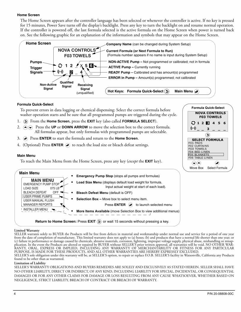
Home Screen
The Home Screen appears after the controller language has been selected or whenever the controller is active. If no key is pressedfor 15 minutes, Power Save turns off the display’s backlight. Press any key to turn the backlight on and resume normal operation.If the controller is powered off, the last formula selected is the active formula on the Home Screen when power is turned backon. See the following graphic for an explanation of the information and symbols that may appear on the Home Screen.
Formula Quick-Select
To prevent errors in data logging or chemical dispensing: Select the correct formula before washer operation starts and be sure that all programmed pumps are triggered during the cycle.
1. From the Home Screen, press the EXIT key (also called FORMULA SELECT). 2. Press the UP or DOWN ARROW to move the selection box to the correct formula.
All formulas appear, but only formulas with programmed pumps are selectable. 3. Press ENTER to start the formula and return to the Home Screen.4. (Optional) Press ENTER to reach the load size or bleach defeat settings.
Main Menu
To reach the Main Menu from the Home Screen, press any key (except the EXIT key).
Limited WarrantySELLER warrants solely to BUYER the Products will be free from defects in material and workmanship under normal use and service for a period of one yearfrom the date of completion of manufacture. This limited warranty does not apply to (a) hoses; (b) and products that have a normal life shorter than one year; or(c) failure in performance or damage caused by chemicals, abrasive materials, corrosion, lightning, improper voltage supply, physical abuse, mishandling or misap-plication. In the event the Products are altered or repaired by BUYER without SELLER’S prior written approval, all warranties will be void. NO OTHER WAR-RANTY, ORAL, EXPRESS OR IMPLIED, INCLUDING ANY WARRANTY OF MERCHANTABILITY OR FITNESS FOR ANY PARTICULARPURPOSE, IS MADE FOR THESE PRODUCTS, AND ALL OTHER WARRANTIES ARE HEREBY EXPRESSLY EXCLUDED. SELLER’S sole obligation under this warranty will be, at SELLER’S option, to repair or replace F.O.B. SELLER’S facility in Watsonville, California any Productsfound to be other than as warranted.Limitation of LiabilitySELLER’S WARRANTY OBLIGATIONS AND BUYERS REMEDIES ARE SOLELY AND EXCLUSIVELY AS STATED HEREIN. SELLER SHALL HAVENO OTHER LIABILITY, DIRECT OR INDIRECT, OF ANY KIND, INCLUDING LIABILITY FOR SPECIAL, INCIDENTAL, OR CONSEQUENTIALDAMAGES OR FOR ANY OTHER CLAIMS FOR DAMAGE OR LOSS RESULTING FROM ANY CAUSE WHATSOEVER, WHETHER BASED ONNEGLIGENCE, STRICT LIABILITY, BREACH OF CONTRACT OR BREACH OF WARRANTY.
NON-ACTIVE Pump – Not programmed or calibrated; not in formula
ACTIVE Pump – Currently running
READY Pump – Calibrated and has amount(s) programmed
ERROR in Pump – Amount(s) programmed; not calibrated
NOVA CONTROLS F03 TOWELS
_ _ 4 _ _ 2
1 2 _ 5 6
Hot Keys: Formula Quick-Select Main Menu
Company Name (can be changed during System Setup)
Current Formula (or Next Formula to Run) (Formula number appears if no name is input during System Setup)
QualifiedSignal
Home Screen
Pumps
TriggerSignals
ReceivingSignal
(unqualified)
Non-ActiveSignal
SELECT FORMULAFO1 PADSF02 CURTAINSFO3 TOWELSF04 BED LINENF05 BLANKETSF06 TABLE LINEN
Formula Quick-Select
Move Box Select Formula
NOVA CONTROLSF03 TOWELS
1 2 3 4 5 6
_ _ 3 _ _ _
EMERGENCY PUMP STOPLOAD SIZE 075 LBBLEACH DEFEAT OFFUSER PRIME PUMPSUSER MANUAL FLUSHMANAGER REPORTS
INSTALLER MENU
MAIN MENU
�
• Emergency Pump Stop (stops all pumps and formulas)
• Load Size Menu (displays default load weight for formula. Input actual weight at start of each load).
• Bleach Defeat Menu (default is OFF)
• Selection Box – Move box to select menu item.
Press ENTER to launch selected menu
• More Items Available (move Selection Box to view additional menus)
Main Menu
Return to Home Screen: Press EXIT or wait 15 seconds without pressing a key.
P/N 20-08808-00C 5
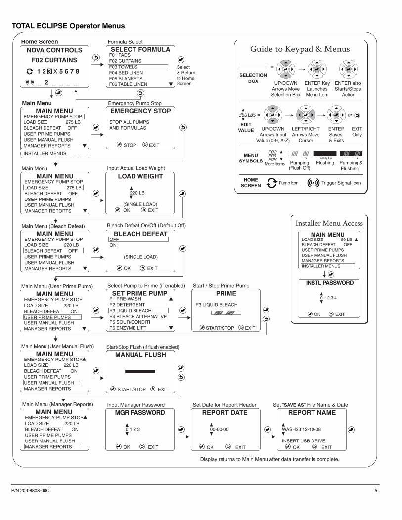
TOTAL ECLIPSE Operator Menus
NOVA CONTROLS
F02 CURTAINS
_ 2 _ _ _ _ �
�
�
�
EMERGENCY PUMP STOPLOAD SIZE 275 LBBLEACH DEFEAT OFFUSER PRIME PUMPSUSER MANUAL FLUSHMANAGER REPORTS
INSTALLER MENUS
Main MenuMAIN MENU
�
�
�
SELECT FORMULAF01 PADSF02 CURTAINSF03 TOWELSF04 BED LINENF05 BLANKETSF06 TABLE LINEN
Formula Select
Select& Returnto HomeScreen
Home Screen
LOAD WEIGHT
220 LB
(SINGLE LOAD) OK EXIT
Input Actual Load Weight
SET PRIME PUMPP1 PRE-WASHP2 DETERGENTP3 LIQUID BLEACHP4 BLEACH ALTERNATIVEP5 SOUR/CONDITIP6 ENZYME LIFT
Bleach Defeat On/Off (Default Off)
Emergency Pump Stop
MAIN MENUEMERGENCY PUMP STOPLOAD SIZE 220 LBBLEACH DEFEAT ONUSER PRIME PUMPSUSER MANUAL FLUSHMANAGER REPORTS
Main Menu (User Prime Pump)
MAIN MENUEMERGENCY PUMP STOPLOAD SIZE 220 LBBLEACH DEFEAT OFFUSER PRIME PUMPSUSER MANUAL FLUSHMANAGER REPORTS
Main Menu (Bleach Defeat)
MAIN MENUEMERGENCY PUMP STOPLOAD SIZE 275 LBBLEACH DEFEAT OFFUSER PRIME PUMPSUSER MANUAL FLUSHMANAGER REPORTS
Main Menu
BLEACH DEFEATOFFON
(SINGLE LOAD)
OK EXIT
EMERGENCY STOP
STOP ALL PUMPSAND FORMULAS
STOP EXIT
PRIME P3 LIQUID BLEACH
START/STOP EXIT
Select Pump to Prime (if enabled) Start / Stop Prime Pump
MGR PASSWORD
OK EXIT
Input Manager Password
0 1 2 3�
�00-00-00�
�
�
�
REPORT DATE
OK EXIT
Set Date for Report Header
WASH23 12-10-08
INSERT USB DRIVE
�
�
REPORT NAME
OK EXIT
Set “SAVE AS” File Name & Date
MANUAL FLUSH
START/STOP EXIT
Start/Stop Flush (if flush enabled)
�MAIN MENUEMERGENCY PUMP STOPLOAD SIZE 220 LBBLEACH DEFEAT ONUSER PRIME PUMPSUSER MANUAL FLUSHMANAGER REPORTS
Main Menu (User Manual Flush)
�MAIN MENUEMERGENCY PUMP STOPLOAD SIZE 220 LBBLEACH DEFEAT ONUSER PRIME PUMPSUSER MANUAL FLUSHMANAGER REPORTS
Main Menu (Manager Reports)
Display returns to Main Menu after data transfer is complete.
1 2 3 X 5 6 7 8 8
�MAIN MENULOAD SIZE 180 LBBLEACH DEFEAT OFFUSER PRIME PUMPSUSER MANUAL FLUSHMANAGER REPORTSINSTALLER MENUS
INSTL PASSWORD
0 1 2 3 4
OK EXIT
�
�
Installer Menu Access
Guide to Keypad & Menus
Pumping(Flush Off)
More Items Flushing Pumping &Flushing
F02 �FO3 FO4 �
SELECTIONBOX UP/DOWN
Arrows MoveSelection Box
ENTER KeyLaunchesMenu Item
ENTER also Starts/Stops
Action
MENUSYMBOLS
HOMESCREEN
=
or
UP/DOWNArrows Input
Value (0-9, A-Z)
LEFT/RIGHTArrows Move
Cursor
ENTERSaves & Exits
EXITOnly
350 LBS�
�
EDITVALUE
=
Steady On
Trigger Signal IconPump Icon
6 P/N 20-08808-00C
01
234
O
K
E
XIT
Mai
n M
enu
MA
IN M
EN
ULO
AD
SIZ
E:
1
75 L
BB
LEA
CH
DE
FE
AT:
OF
FU
SE
R P
RIM
E P
UM
PS
US
ER
MA
NU
AL
FLU
SH
MA
NA
GE
R R
EP
OR
TS
INS
TALL
ER
ME
NU
S
Hom
e S
cree
n
INS
TAL
LE
R M
EN
UIN
STA
LLE
R S
ER
VIC
EIN
ITIA
L S
YS
TE
M S
ET
UP
PR
OG
RA
M F
OR
MU
LAS
DAT
A T
RA
NS
FE
RS
ET
UN
ITS
OF
ME
AS
UR
E
Inst
alle
r Top
Lev
el M
enu
Inpu
t Ins
talle
r P
assw
ord
INS
TL
PA
SS
WO
RD
UN
ITS
-ME
AS
UR
ES
AE
/ IM
PE
RIA
L (
LB/O
Z)
ME
TR
IC
(K
G/M
L)
5.
Set
Uni
ts o
f M
easu
re
NO
VA C
ON
TR
OL
S F
03 T
OW
EL
S
_
_
4 _
_
2
1 2
3
_
_
3.1.
2 A
dd P
umps
to F
orm
ula
F01
PU
MP
SP
1 P
RE
-WA
SH
P2
DE
TE
RG
EN
T
P3
LIQ
UID
BLE
AC
H
P4
BLE
AC
H A
LT
P5
SO
UR
/CO
ND
ITI
P
6 E
NZ
YM
E L
IFT
3.1.
3 P
ump
Set
tings
F01
P1
P1
D
ELA
Y
0 0
0 S
EC
P1A
AM
OU
NT
0
0.00
OZ
P1B
AM
OU
NT
0
0.00
OZ
P1C
AM
OU
NT
0
0.00
OZ
PR
OG
RA
M F
OR
MU
LAS
F01
F02
CU
RTA
INS
F03
TO
WE
LS
F04
BE
D L
INE
N
F
05 B
LAN
KE
TS
F06
TA
BLE
LIN
EN
3. F
orm
ula
Pro
gra
mm
ing
F01
PU
MP
SE
TT
ING
S
SE
T D
EFA
ULT
WE
IGH
TS
ET
CO
UN
T P
UM
PE
DIT
NA
ME
CLE
AR
FO
RM
ULA
3.1
Set
For
mul
a3.
2 D
efau
lt Lo
ad W
eigh
t3.
3 S
et C
ount
Pum
p3.
4 E
dit F
orm
ula
Nam
e3.
5 C
lear
For
mul
a
PO
G R
esta
uran
tsB
LS S
ervi
ces
Ecl
ipse
Hot
elH
ospi
tal S
ettin
gsIn
tern
atio
nal H
otel
AA
Sch
ool D
istr
ict
SE
TU
P F
ILE
4.2
Rea
d S
etup
- S
elec
t File
to
load
from
US
B to
Con
trolle
r4.
3 W
rite
Set
up -
Nam
e Fi
le b
eing
sen
t
(fro
m C
ontro
ller t
o U
SB
flas
h dr
ive)
DA
TA T
RA
NS
FE
RW
RIT
E R
EP
OR
TS
RE
AD
SE
TU
PW
RIT
E S
ET
UP
UP
DAT
E F
IRM
WA
RE
4.1
Set
Dat
e fo
r Rep
ort H
eade
r
RE
PO
RT
DA
TE
01-
01-0
8
O
K
EX
IT
RE
PO
RT
NA
ME
_DA
TE
HI-
CA
P 0
1-01
-08
INS
ER
T U
SB
DR
IVE
O
K
EX
IT
4.1.
2 S
et “S
AV
E A
S”
F
ile N
ame
& D
ate
4. U
ploa
d /
Dow
nloa
d D
ata
1.5
Cle
ar D
ata
Log
ZE
RO
DA
TA L
OG
WA
RN
ING
! ALL
LO
GS
(LO
AD
S &
VO
LUM
ES
)W
ILL
BE
CLE
AR
ED
!
O
K
E
XIT
1. S
ervi
ce /
Rou
tine
Mai
nten
ance
INS
TAL
LE
R S
ER
VIC
ES
ER
VIC
E P
UM
PS
VIE
W L
OA
D C
OU
NT
VIE
W L
OA
D W
EIG
HT
VIE
W A
MO
UN
T P
UM
PE
DC
LEA
R D
ATA
LO
G
1.1
Pum
p M
aint
enan
ce /S
ervi
ce
SE
RV
ICE
PU
MP
SP
RIM
E P
UM
PP
UM
P C
ALI
BR
ATIO
NN
AM
E P
UM
PS
EN
TE
R P
RO
DU
CT
CO
ST
SD
ATE
TU
BE
CH
AN
GE
D
1.2
Vie
w L
oad
Cou
nt
TOTA
L L
OA
D C
OU
NT
F01
PA
DS
0
F02
CU
RTA
INS
0F
03 T
OW
ELS
0
F04
BE
D L
INE
N
0F
05 B
LAN
KE
TS
0
F06
TA
BLE
LIN
EN
0
1.3
Vie
w L
oad
Wei
ght
TOTA
L W
EIG
HT
F01
PA
DS
0
F02
CU
RTA
INS
0F
03 T
OW
ELS
0
F04
BE
D L
INE
N
0F
05 B
LAN
KE
TS
0
F06
TA
BLE
LIN
EN
0
1.4
Vie
w A
mou
nt P
umpe
d
PU
MP
ED
(G
AL
)P
1 P
RE
-WA
SH
0.0
P
2 D
ET
ER
GE
NT
0
.0P
3 LI
QU
ID B
LEA
C
0.0
P4
BLE
AC
H A
LT
0.
0P
5 S
OU
R/C
ON
DIT
I
0.0
P6
EN
ZY
ME
LIF
T
0.0
0 1
2 3
4
O
K
EX
IT
�
�
INS
T P
AS
SW
OR
D
�
�
�
�
MG
R P
AS
SW
OR
D2.
5 E
dit M
achi
ne N
ame
2.1
Edi
t Ins
talle
r Pas
swor
d2.
2 E
dit M
anag
er P
assw
ord
2.3
Set
-up
Ope
ratin
g M
ode
HO
TE
L E
CLI
PS
E -
67
O
K
EX
IT
�
�
AC
CO
UN
T N
AM
E2.
4 E
dit A
ccou
nt N
ame
2.6
Edi
t Com
pany
Nam
e
2.8
Set
Cyc
le T
ime
Lim
it
9 0
MIN
UT
ES
(0 =
OF
F)
O
K
EX
IT
�
�
CY
CL
E T
IME
LIM
IT2.
9 S
et T
rigge
r Sig
nal F
ilter
2 S
EC
ON
DS
10 S
EC
ON
DS
20 S
EC
ON
DS
30 S
EC
ON
DS
60 S
EC
ON
DS
90 S
EC
ON
DS
TR
IGG
ER
FIL
TE
R2.
10 A
uto-
Form
ula
Sel
ect
2.11
Use
r P
rime
Ena
ble
2.12
Adj
ust S
cree
n C
ontra
st2.
13 C
lear
Con
trolle
r Set
tings
SY
ST
EM
SE
TU
PE
DIT
INS
T P
AS
SW
OR
D
ED
IT M
GR
PA
SS
WO
RD
O
PE
RAT
ION
MO
DE
ED
IT A
CC
OU
NT
NA
ME
ED
IT M
AC
HIN
E N
AM
EE
DIT
CO
MPA
NY
NA
ME
SE
T P
UM
P IN
TE
RFA
CE
SE
T C
YC
LE T
IME
SIG
NA
L F
ILT
ER
TIM
ES
ET
AF
S T
RIG
GE
RS
ET
US
ER
PR
IME
SE
T L
CD
CO
NT
RA
ST
CLE
AR
SE
TT
ING
SV
IEW
SO
FT
WA
RE
ID
� �
�
�
�
2. I
niti
al S
yste
m S
etu
p
2.14
Sof
twar
e Ve
rsio
n ID
TOTA
L E
CLI
PS
EP
/N:
95-0
8489
-00A
RE
V:
687
SO
FT
WA
RE
VE
R
�
�
�
�
SE
TU
P N
AM
E
H
OT
EL
17
INS
ER
T U
SB
DR
IVE
O
K
EX
IT
�
�
�
�
STA
ND
AR
DR
ELA
YE
VE
NT
GR
OU
PO
CC
UR
RE
NC
E
OP
ER
AT
ION
MO
DE
2.7
Set
Pum
p In
terfa
ce
(and
Flu
sh T
ime,
if n
eede
d)
NO
N-F
LUS
HE
CLI
PS
E F
LUS
H P
. I.
OR
ION
I I
FLU
SH
P. I
.8-
PU
MP
FLU
SH
P. I
.
PU
MP
INT
ER
FAC
E
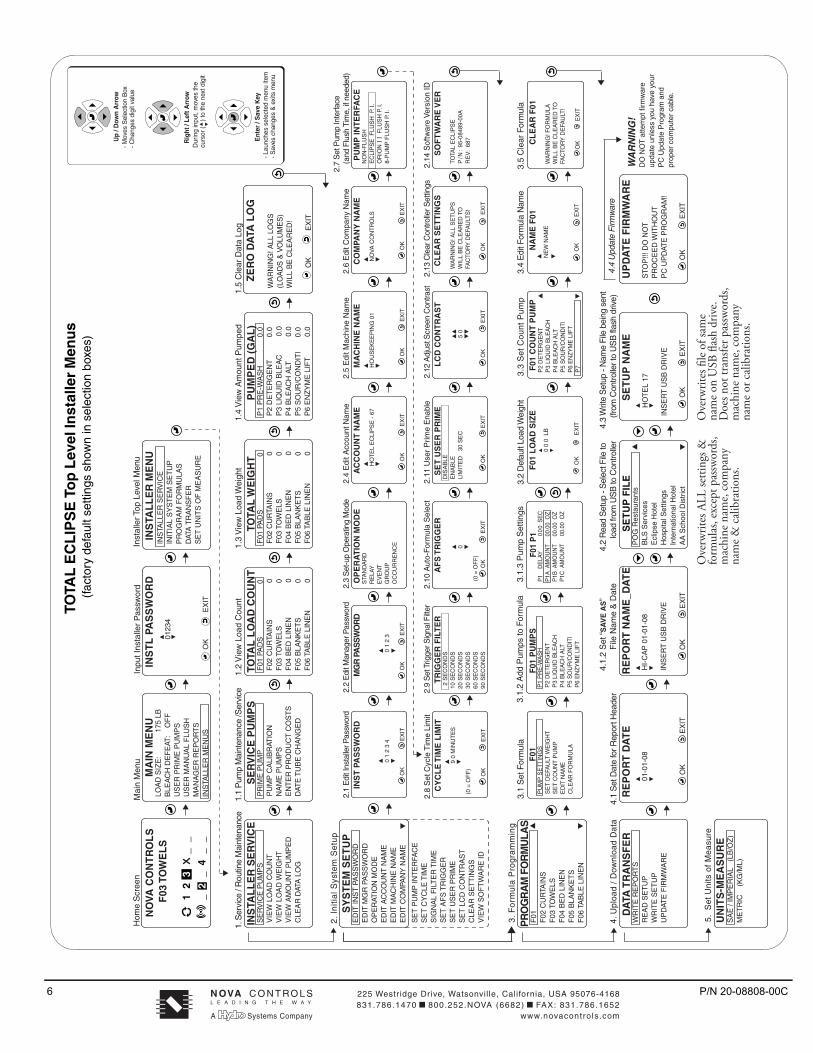
Ove
rwrit
es fi
le of
sam
e na
me o
n U
SB fl
ash
driv
e. D
oes n
ot tr
ansfe
r pas
swor
ds,
mac
hine
nam
e, co
mpa
ny
nam
e or c
alib
ratio
ns.
Ove
rwrit
es A
LL se
tting
s &
form
ulas
, exc
ept p
assw
ords
, m
achi
ne n
ame,
com
pany
na
me &
cal
ibra
tions
.
WA
RN
ING
! ALL
SE
TU
PS
W
ILL
BE
CLE
AR
ED
TO
FAC
TOR
Y D
EFA
ULT
S!
O
K
EX
IT
CL
EA
R S
ET
TIN
GS
F01
LO
AD
SIZ
E
0 0
0 L
B
O
K
E
XIT
�
�
NA
ME
F01
NE
W N
AM
E
O
K
EX
IT
�
�
P2
DE
TE
RG
EN
T
�
P
3 LI
QU
ID B
LEA
CH
P
4 B
LEA
CH
ALT
P
5 S
OU
R/C
ON
DIT
I
P6
EN
ZY
ME
LIF
TP
7
�
F01
CO
UN
T P
UM
PC
LE
AR
F01
WA
RN
ING
! FO
RM
ULA
W
ILL
BE
CLE
AR
ED
TO
FAC
TOR
Y D
EFA
ULT
!
O
K
E
XIT
4.4
Upd
ate
Firm
war
e
UP
DA
TE
FIR
MW
AR
E
STO
P!!!
DO
NO
TP
RO
CE
ED
WIT
HO
UT
PC
UP
DAT
E P
RO
GR
AM
!
O
K
EX
IT
0
(0
= O
FF
)
OK
E
XIT
AF
S T
RIG
GE
RD
ISA
BLE
EN
AB
LELI
MIT
ED
30
SE
C
O
K
EX
IT
SE
T U
SE
R P
RIM
E
�
��
�
5 0
O
K
EX
IT
LC
D C
ON
TR
AS
T
0
1 2
3
O
K
EX
IT
H
OU
SE
KE
EP
ING
01
O
K
EX
IT
�
�MA
CH
INE
NA
ME
N
OVA
CO
NT
RO
LS
O
K
EX
IT
�
�
CO
MPA
NY
NA
ME
WA
RN
ING
! D
O N
OT
atte
mpt
firm
war
e up
date
unl
ess
you
have
you
rP
C U
pdat
e P
rogr
am a
nd
prop
er c
ompu
ter
cabl
e.
Ent
er /
Sav
e K
ey- L
aunc
hes
sele
cted
men
u ite
m- S
aves
cha
nges
& e
xits
men
u
Up
/ Dow
n A
rrow
- Mov
es S
elec
tion
Box
- Cha
nges
dig
it va
lue
Rig
ht /
Left
Arr
owD
urin
g in
put,
mov
es th
ecu
rsor
( )
to th
e ne
xt d
igit
� �
TOTA
L E
CL
IPS
E T
op
Lev
el In
stal
ler
Men
us
(fac
tory
def
ault
setti
ngs
show
n in
sel
ectio
n bo
xes)
N OVA C O N T RO L S
A Systems Company www.novacontrols.com831.786.1470�800.252.NOVA (6682)�FAX: 831.786.1652225 Westr idge Drive, Watsonville, California, USA 95076-4168
L E A D I N G T H E W A Y