Embed Size (px)
Citation preview
NOTICE INVITING TENDER
FOR
PRE-PROJECT ELECTRICAL WORKS (SUPPLY & ERECTION)
AT SINDRI, JHARKHAND
[PACKAGE-V]
NIT NO. : PNPM/5002/E/201
PREPARED AND ISSUED BY
PROJECTS & DEVELOPMENT INDIA LTD. (A Govt. of India Enterprise)
PDIL Bhawan, A-14, Sector-1, NOIDA-201301, U.P., India
January, 2018
PROJECTS & DEVELOPMENT INDIA LIMITED
PNPM/5002/E/201/S-A /LIB 0
DOC. NO. REV.
Page 1 of 3
FORM NO: 02-0000-0021 F2 REV3 All rights reserved
LETTER INVITING BID
NIT NO. : PNPM/5002/E/201
SUBJECT : PRE-PROJECT ELECTRICAL WORKS (SUPPLY & ERECTION) AT
SINDRI, JHARKHAND [PACKAGE-V]
(OPEN DOMESTIC COMPETITIVE BIDDING) Dear Sir(s), Projects and Development India Limited (PDIL), hereinafter referred to as CONSULTANT on behalf of Hindustan Urvarak & Rasayan Ltd. (HURL), hereinafter referred as OWNER, has the pleasure of inviting eligible bidders to submit Bid ONLINE through Central Public Procurement (CPP) Portal in Single Phase Two Bid System, for the subject Project in compliance with the NIT. The entire set of Bidding documents is also placed on the website at HURL website www.hurl.net.in, PDIL website www.pdilin.com, and CPP Portal http://eprocure.gov.in/cppp/ SCOPE OF WORK Tapping of power from DVC’s metering panel in metering room “CS/S1” (by the contractor) to RMU which is to be installed in CS/S2 (by the contractor) and then further distribution to various load shall be in the bidder’s scope. Supply and delivery FOR site in well packed condition of the electrical equipments and accessories specified herein. Supply, Erection (including transportation & handling), testing and commissioning of all electrical equipments and accessories specified herein. The scope of work shall also include digging of earth and refilling for directly buried cables, earth strips, cable protection pipes, earth pits, ground mounted lighting pole foundations; civil works such as making earth pit inspection chambers with covers, grouting of equipment base plate, channels, supports and foundation bolts, chipping of concrete or in brick work for earth strips, pipes or other minor chipping for foundation preparation, if required, cutting holes in walls for racks, risers, light fitting brackets, sealing of cable entries and making good the same after installation of the equipment and levelling, and other minor similar jobs as per directions of Owner / Engineer-in-Charge. All major Civil work (like Substation building, making all foundations and cable trenches etc) and minor civil work (like cutting, chipping, grouting, making opening in floor / wall etc. for equipment foundation and cabling work) pertaining to electrical equipment are in the scope of work of the contractor and shall be done as per technical specification of civil enclosed elsewhere in the NIT. The contractor shall obtain the necessary clearance from Electrical Inspector of Jharkhand for complete electrical installation. All necessary drawings, calculations, test certificates and record of site tests etc. as required by the Inspector shall be furnished. Any modification / rectification as required by Electrical Inspector shall be carried out free of cost by the contractor. However, necessary statutory fee shall be deposited by the owner. Operation & Maintenance of all the electrical equipment supplied/ erected/ tested/ commissioned by the contractor shall be in the scope of the bidder.
TENDER DOCUMENT FOR PRE-PROJECT ELECTRICAL WORKS (SUPPLY & ERECTION) AT
SINDRI, JHARKHAND
LETTER INVITING BID
PNPM/5002/E/201/S-A /LIB 0
DOC. NO. REV.
Page 2 of 3
FORM NO: 02-0000-0021 F2 REV3 All rights reserved
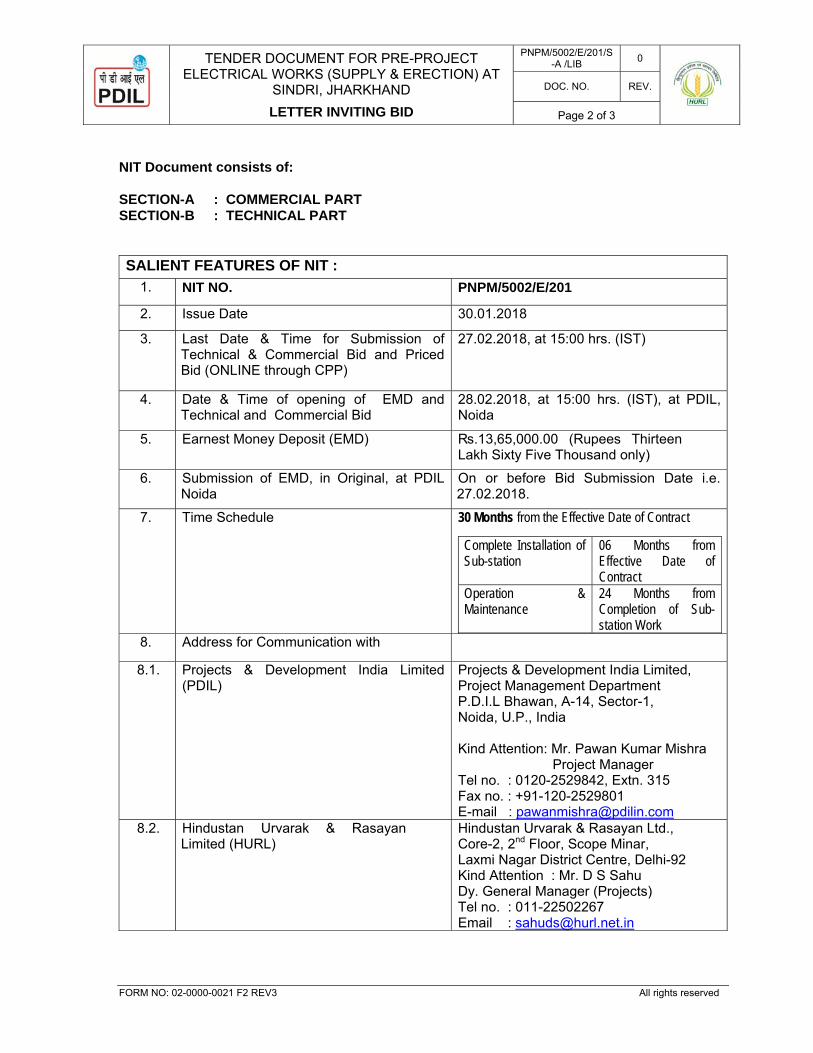
NIT Document consists of: SECTION-A : COMMERCIAL PART SECTION-B : TECHNICAL PART
SALIENT FEATURES OF NIT : 1. NIT NO. PNPM/5002/E/201
2. Issue Date 30.01.2018
3. Last Date & Time for Submission of Technical & Commercial Bid and Priced Bid (ONLINE through CPP)
27.02.2018, at 15:00 hrs. (IST)
4. Date & Time of opening of EMD and Technical and Commercial Bid
28.02.2018, at 15:00 hrs. (IST), at PDIL, Noida
5. Earnest Money Deposit (EMD) ₨.13,65,000.00 (Rupees Thirteen Lakh Sixty Five Thousand only)
6. Submission of EMD, in Original, at PDIL Noida
On or before Bid Submission Date i.e. 27.02.2018.
7. Time Schedule 30 Months from the Effective Date of Contract Complete Installation of Sub-station
06 Months from Effective Date of Contract
Operation & Maintenance
24 Months from Completion of Sub-station Work
8. Address for Communication with
8.1. Projects & Development India Limited (PDIL)
Projects & Development India Limited, Project Management Department P.D.I.L Bhawan, A-14, Sector-1, Noida, U.P., India Kind Attention: Mr. Pawan Kumar Mishra
Project Manager Tel no. : 0120-2529842, Extn. 315 Fax no. : +91-120-2529801 E-mail : [email protected]
8.2. Hindustan Urvarak & Rasayan Limited (HURL)
Hindustan Urvarak & Rasayan Ltd., Core-2, 2nd Floor, Scope Minar, Laxmi Nagar District Centre, Delhi-92 Kind Attention : Mr. D S Sahu Dy. General Manager (Projects) Tel no. : 011-22502267 Email : [email protected]
TENDER DOCUMENT FOR PRE-PROJECT ELECTRICAL WORKS (SUPPLY & ERECTION) AT
SINDRI, JHARKHAND
LETTER INVITING BID
PNPM/5002/E/201/S-A /LIB 0
DOC. NO. REV.
Page 3 of 3
FORM NO: 02-0000-0021 F2 REV3 All rights reserved
8.3. Contact Person for Site visit Contact Person: Mr. O.P. Khushwaha Site Manager (Sindri) HURL,Fertilizer Plant , Sindri Mob.: +91-9431106029 E-mail: [email protected]
8.4. NIT overview on websites “Letter Inviting Bid” & “Instruction to Bidders” is available at following websites:
HURL (www.hurl.net.in) PDIL (www.pdilin.com) CPP Portal (www.eprocure.gov.in)
The bidder shall submit the bid ONLINE through Central Public Procurement (CPP) Portal. However, Earnest Money Deposit (EMD)/ Documentary evidence regarding EMD Exemption, No deviation certificate and Integrity Pact, in original, shall be submitted at PDIL, Noida on or before Bid Submission Date. OWNER / CONSULTANT reserve the right to accept/reject any or all Bids without assigning any reason whatsoever. Bids complete in all respects should reach on or before the Bid Due Date and time. Bids through Fax / E-mails will not be accepted. OWNER / CONSULTANT take no responsibility for delay, loss or non-receipt of Bid sent by post/courier. Please be noted that all the dates mentioned herewith are firm and OWNER / CONSULTANT expect strict adherence since this is a priority project. Transfer of Bidding Document is not permissible. Bidder may depute their representative with proper authorization letter to attend Technical and commercial opening of bids. Eligible bidders are requested to confirm their intention, within seven (07) days from the placement of NIT at CPP Portal, to participate in subject bidding through a letter or fax message Thanking you, For & on behalf of Projects & Development India Ltd. PAWAN KUMAR MISHRA PROJECT MANAGER
TENDER DOCUMENT FOR PRE-PROJECT ELECTRICAL WORKS (SUPPLY & ERECTION)
AT SINDRI, JHARKHAND [PACKAGE-V]
MASTER INDEX
PNPM/5002/E/201/MI 0
DOC. NO. REV.
Page 1 of 2
FORM NO: 02-0000-0021 F 2 REV 3 All rights reserved
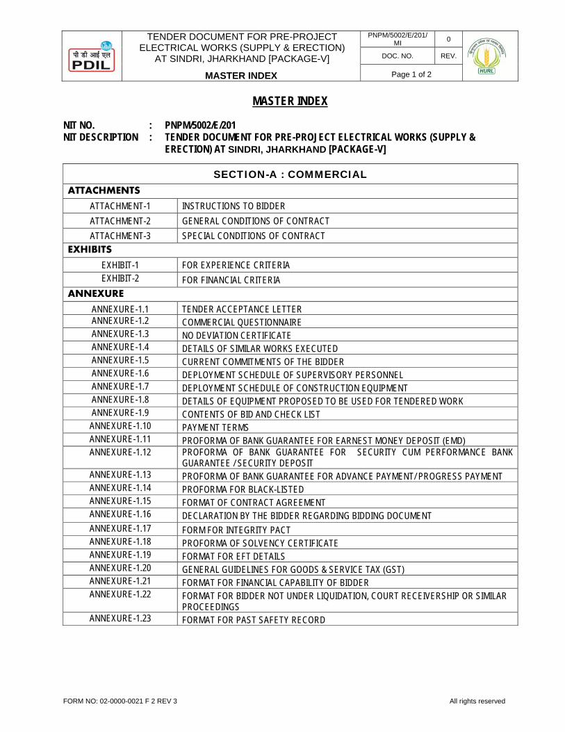
MASTER INDEX
NIT NO. : PNPM/5002/E/201 NIT DESCRIPTION : TENDER DOCUMENT FOR PRE-PROJECT ELECTRICAL WORKS (SUPPLY & ERECTION) AT SINDRI, JHARKHAND [PACKAGE-V]
SECTION-A : COMMERCIAL ATTACHMENTS
ATTACHMENT-1 INSTRUCTIONS TO BIDDER ATTACHMENT-2 GENERAL CONDITIONS OF CONTRACT ATTACHMENT-3 SPECIAL CONDITIONS OF CONTRACT
EXHIBITS EXHIBIT-1 FOR EXPERIENCE CRITERIA EXHIBIT-2 FOR FINANCIAL CRITERIA
ANNEXURE
ANNEXURE-1.1 TENDER ACCEPTANCE LETTER ANNEXURE-1.2 COMMERCIAL QUESTIONNAIRE ANNEXURE-1.3 NO DEVIATION CERTIFICATE ANNEXURE-1.4 DETAILS OF SIMILAR WORKS EXECUTED ANNEXURE-1.5 CURRENT COMMITMENTS OF THE BIDDER ANNEXURE-1.6 DEPLOYMENT SCHEDULE OF SUPERVISORY PERSONNEL ANNEXURE-1.7 DEPLOYMENT SCHEDULE OF CONSTRUCTION EQUIPMENT ANNEXURE-1.8 DETAILS OF EQUIPMENT PROPOSED TO BE USED FOR TENDERED WORK ANNEXURE-1.9 CONTENTS OF BID AND CHECK LIST ANNEXURE-1.10 PAYMENT TERMS ANNEXURE-1.11 PROFORMA OF BANK GUARANTEE FOR EARNEST MONEY DEPOSIT (EMD) ANNEXURE-1.12 PROFORMA OF BANK GUARANTEE FOR SECURITY CUM PERFORMANCE BANK
GUARANTEE / SECURITY DEPOSIT ANNEXURE-1.13 PROFORMA OF BANK GUARANTEE FOR ADVANCE PAYMENT/ PROGRESS PAYMENT ANNEXURE-1.14 PROFORMA FOR BLACK-LISTED ANNEXURE-1.15 FORMAT OF CONTRACT AGREEMENT ANNEXURE-1.16 DECLARATION BY THE BIDDER REGARDING BIDDING DOCUMENT ANNEXURE-1.17 FORM FOR INTEGRITY PACT ANNEXURE-1.18 PROFORMA OF SOLVENCY CERTIFICATE ANNEXURE-1.19 FORMAT FOR EFT DETAILS ANNEXURE-1.20 GENERAL GUIDELINES FOR GOODS & SERVICE TAX (GST) ANNEXURE-1.21 FORMAT FOR FINANCIAL CAPABILITY OF BIDDER ANNEXURE-1.22 FORMAT FOR BIDDER NOT UNDER LIQUIDATION, COURT RECEIVERSHIP OR SIMILAR
PROCEEDINGS ANNEXURE-1.23 FORMAT FOR PAST SAFETY RECORD
TENDER DOCUMENT FOR PRE-PROJECT ELECTRICAL WORKS (SUPPLY & ERECTION)
AT SINDRI, JHARKHAND [PACKAGE-V]
MASTER INDEX
PNPM/5002/E/201/MI 0
DOC. NO. REV.
Page 2 of 2
FORM NO: 02-0000-0021 F 3 REV 4 All rights reserved
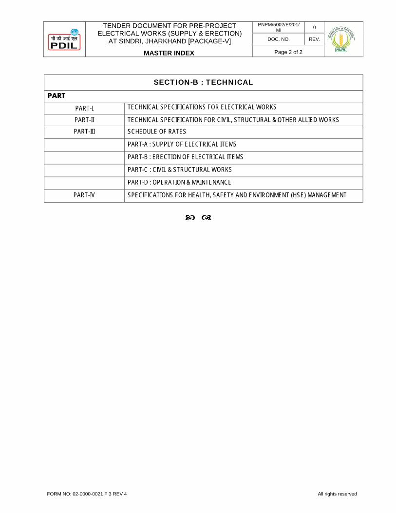
SECTION-B : TECHNICAL
PART
PART-I TECHNICAL SPECIFICATIONS FOR ELECTRICAL WORKS
PART-II TECHNICAL SPECIFICATION FOR CIVIL, STRUCTURAL & OTHER ALLIED WORKS PART-III SCHEDULE OF RATES
PART-A : SUPPLY OF ELECTRICAL ITEMS
PART-B : ERECTION OF ELECTRICAL ITEMS
PART-C : CIVIL & STRUCTURAL WORKS
PART-D : OPERATION & MAINTENANCE
PART-IV SPECIFICATIONS FOR HEALTH, SAFETY AND ENVIRONMENT (HSE) MANAGEMENT
PROJECTS & DEVELOPMENT INDIA LIMITED
PNPM/5002/E/201/S-A/AT-1.0 0
DOC. NO. REV.
Page 1 of 29
FORM NO: 02-0000-0021F1 REV3 All rights reserved
SECTION-A : COMMERCIAL
ATTACHMENT – 1.0
INSTRUCTIONS TO BIDDERS
0 08.01.2018 FOR ISSUE PKM PKM RRKP 02.11.2017 FOR REVIEW PKM PKM RRK
REV. DATE PURPOSE PREPARED REVIEWED APPROVED
TENDER DOCUMENT FOR PRE-PROJECT ELECTRICAL WORKS (SUPPLY & ERECTION)
AT SINDRI, JHARKHAND [PACKAGE-V]
INSTRUCTIONS TO BIDDERS
PNPM/5002/E/201/S-A/AT-1.0 0
DOC. NO. REV.
Page 2 of 29
FORM NO: 02-0000-0021F2 REV3 All rights reserved
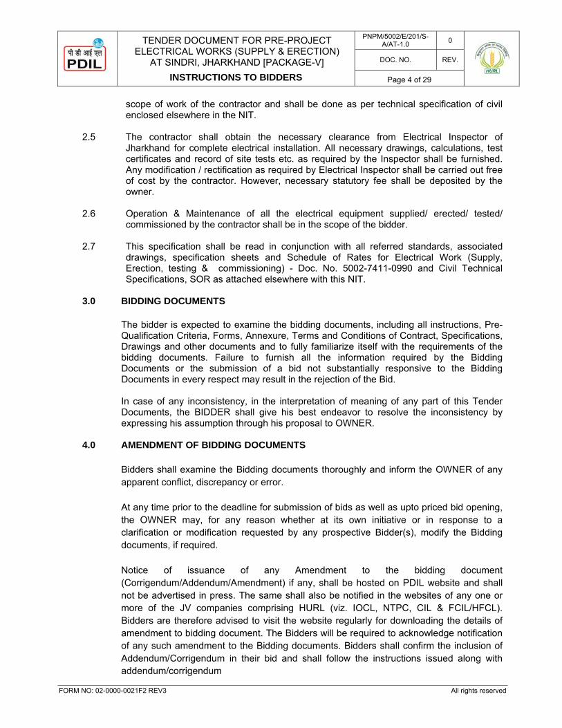
TABLE OF CONTENTS
1.0 INTRODUCTION ......................................................................................................................................................... 3 2.0 SCOPE OF PROPOSAL............................................................................................................................................. 3 3.0 BIDDING DOCUMENTS ............................................................................................................................................. 4 4.0 AMENDMENT OF BIDDING DOCUMENTS .............................................................................................................. 4 5.0 LANGUAGE OF THE BID ........................................................................................................................................... 5 6.0 TIME SCHEDULE ....................................................................................................................................................... 5 7.0 SIGNATURE ON BIDS ............................................................................................................................................... 5 8.0 PRE-QUALIFICATION CRITERIA (PQC) .................................................................................................................. 6 9.0 EARNEST MONEY DEPOSIT (EMD) ........................................................................................................................ 8 10.0 COST OF BIDS ......................................................................................................................................................... 10 11.0 MODIFICATION AND WITHDRAWAL OF BIDS ..................................................................................................... 10 12.0 INFORMATION REQUIRED WITH THE BID ........................................................................................................... 11 13.0 PRELIMINARY EXAMINATION ................................................................................................................................ 11 14.0 LOCAL CONDITIONS ............................................................................................................................................... 12 15.0 PRICE BASIS & CURRENCY OF BIDS ................................................................................................................... 13 16.0 CONSORTIUM BIDS ................................................................................................................................................ 13 17.0 NUMBER OF BIDS ................................................................................................................................................... 13 18.0 CONFIDENTIALITY OF DOCUMENTS ................................................................................................................... 13 19.0 TAXES AND DUTIES ............................................................................................................................................... 13 20.0 ZERO DEVIATION AND REJECTION CRITERIA ................................................................................................... 14 21.0 SUBMISSION OF BIDS ............................................................................................................................................ 15 22.0 DEADLINE FOR SUBMISSION OF BIDS: ............................................................................................................... 20 23.0 OPENING OF BIDS .................................................................................................................................................. 21 24.0 CORRECTION OF ERRORS ................................................................................................................................... 22 25.0 POLICY FOR BID UNDER CONSIDERATION ........................................................................................................ 22 26.0 DISCUSSIONS WITH BIDDERS DURING TECHNO- COMERCIAL EVALUATION ............................................. 23 27.0 EFFECT AND VALIDITY OF BID ............................................................................................................................. 23 28.0 COMPLETE SCOPE OF SUPPLIES / WORK ........................................................................................................ 24 29.0 FIRM RATES / PRICE .............................................................................................................................................. 24 30.0 EVALUATION AND COMPARISON OF BIDS ......................................................................................................... 24 31.0 PRICE VARIATION ................................................................................................................................................... 25 32.0 REBATE .................................................................................................................................................................... 25 33.0 CONTACTING OWNER ........................................................................................................................................... 25 34.0 AWARD OF CONTRACT .......................................................................................................................................... 25 35.0 SIGNING OF CONTRACT ........................................................................................................................................ 26 36.0 OWNER’S RIGHT TO ACCEPT / REJECT BIDS .................................................................................................... 26 37.0 CONTRACT SECURITY CUM PERFORMANCE BANK GUARANTEE ................................................................. 26 38.0 INCOME TAX & CORPORATE TAX ........................................................................................................................ 27 39.0 GENERAL INSTRUCTIONS ..................................................................................................................................... 27 40.0 INTEGRITY PACT .................................................................................................................................................... 28 41.0 RATES FOR EXTRA ITEMS .................................................................................................................................... 28 42.0 BIDDER TO QUOTE FOR ALL ITEMS .................................................................................................................... 29 43.0 BIDDER TO SIGN ALL PAGES ................................................................................................................................ 29 44.0 ERASURES AND ALTERATIONS ........................................................................................................................... 29 45.0 INCOMPLETE AND LATE TENDER ........................................................................................................................ 29 46.0 EXECUTION OF CONTRACT .................................................................................................................................. 29

TENDER DOCUMENT FOR PRE-PROJECT ELECTRICAL WORKS (SUPPLY & ERECTION)
AT SINDRI, JHARKHAND [PACKAGE-V]
INSTRUCTIONS TO BIDDERS
PNPM/5002/E/201/S-A/AT-1.0 0
DOC. NO. REV.
Page 3 of 29
FORM NO: 02-0000-0021F2 REV3 All rights reserved
INSTRUCTION TO BIDDERS
1.0 INTRODUCTION 1.1. Government of India has formed a joint venture company of M/s. National Thermal Power
Corporation Ltd. (NTPC), M/s. Coal India Limited (CIL), M/s. Indian Oil Corporation Ltd. (IOCL) & FCIL/HFCL by name M/s Hindustan Urvarak & Rasayan Ltd. (HURL) hereinafter also referred to as “OWNER”, for setting up a brown field Ammonia Urea Complex along with its associated offsite & utility facilities at existing fertilizer complex of FCIL, Sindri, in the State of Jharkhand.
1.1.1 Projects & Development India Ltd. (PDIL) has been retained as Consultant for providing
Engineering Consultancy Services and Project Management Services for the aforesaid project.
1.2 LOCATION OF THE PROJECT SITE
The existing Sindri Fertilizer unit of Fertilizer Corporation of India Ltd. (FCIL) is located in the Dhanbad district of Jharkhand. Sindri Unit is located about 20 kms away from the district headquarters of Dhanbad district of Jharkhand State. Sindri is well connected by road and rail to the district headquarters of Dhanbad . The rail line connects Sindri (via Dhanbad) to the all important cities of India. Ranchi is the nearest airport (apprx. 180 km) away from Sindri.
2.0 SCOPE OF WORK
The scope of work shall include the following:- 2.1 Tapping of power from DVC’s metering panel in metering room “CS/S1” (by the contractor)
to RMU which is to be installed in CS/S2 (by the contractor) and then further distribution to various load shall be in the bidder’s scope (Refer attached Plot Plan) HURL, Sindri plant Site.
2.2 Supply and delivery FOR site in well packed condition of the electrical equipments and
accessories specified herein. 2.3 Supply, Erection (including transportation & handling), testing and commissioning of all
electrical equipments and accessories specified herein. The scope of work shall also include digging of earth and refilling for directly buried cables, earth strips, cable protection pipes, earth pits, ground mounted lighting pole foundations; civil works such as making earth pit inspection chambers with covers, grouting of equipment base plate, channels, supports and foundation bolts, chipping of concrete or in brick work for earth strips, pipes or other minor chipping for foundation preparation, if required, cutting holes in walls for racks, risers, light fitting brackets, sealing of cable entries and making good the same after installation of the equipment and levelling, and other minor similar jobs as per directions of Owner / Engineer-in-Charge.
2.4 All major Civil work (like Substation building, making all foundations and cable trenches
etc) and minor civil work (like cutting, chipping, grouting, making opening in floor / wall etc. for equipment foundation and cabling work) pertaining to electrical equipment are in the
TENDER DOCUMENT FOR PRE-PROJECT ELECTRICAL WORKS (SUPPLY & ERECTION)
AT SINDRI, JHARKHAND [PACKAGE-V]
INSTRUCTIONS TO BIDDERS
PNPM/5002/E/201/S-A/AT-1.0 0
DOC. NO. REV.
Page 4 of 29
FORM NO: 02-0000-0021F2 REV3 All rights reserved
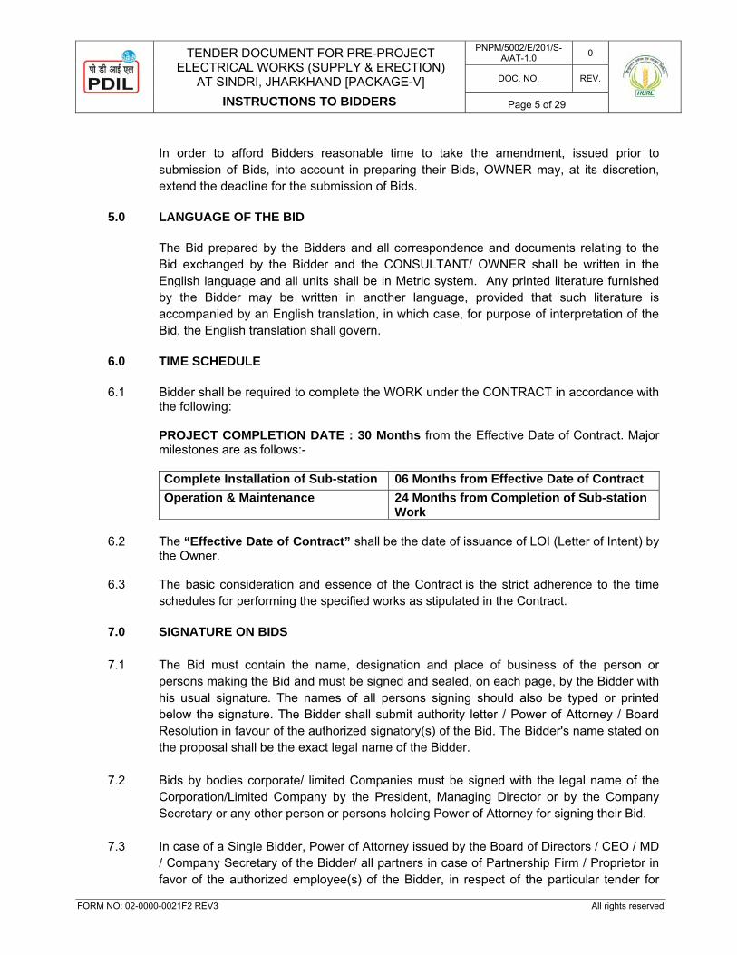
scope of work of the contractor and shall be done as per technical specification of civil enclosed elsewhere in the NIT.
2.5 The contractor shall obtain the necessary clearance from Electrical Inspector of
Jharkhand for complete electrical installation. All necessary drawings, calculations, test certificates and record of site tests etc. as required by the Inspector shall be furnished. Any modification / rectification as required by Electrical Inspector shall be carried out free of cost by the contractor. However, necessary statutory fee shall be deposited by the owner.
2.6 Operation & Maintenance of all the electrical equipment supplied/ erected/ tested/
commissioned by the contractor shall be in the scope of the bidder. 2.7 This specification shall be read in conjunction with all referred standards, associated
drawings, specification sheets and Schedule of Rates for Electrical Work (Supply, Erection, testing & commissioning) - Doc. No. 5002-7411-0990 and Civil Technical Specifications, SOR as attached elsewhere with this NIT.
3.0 BIDDING DOCUMENTS
The bidder is expected to examine the bidding documents, including all instructions, Pre-Qualification Criteria, Forms, Annexure, Terms and Conditions of Contract, Specifications, Drawings and other documents and to fully familiarize itself with the requirements of the bidding documents. Failure to furnish all the information required by the Bidding Documents or the submission of a bid not substantially responsive to the Bidding Documents in every respect may result in the rejection of the Bid.
In case of any inconsistency, in the interpretation of meaning of any part of this Tender Documents, the BIDDER shall give his best endeavor to resolve the inconsistency by expressing his assumption through his proposal to OWNER.
4.0 AMENDMENT OF BIDDING DOCUMENTS
Bidders shall examine the Bidding documents thoroughly and inform the OWNER of any apparent conflict, discrepancy or error. At any time prior to the deadline for submission of bids as well as upto priced bid opening, the OWNER may, for any reason whether at its own initiative or in response to a clarification or modification requested by any prospective Bidder(s), modify the Bidding documents, if required. Notice of issuance of any Amendment to the bidding document (Corrigendum/Addendum/Amendment) if any, shall be hosted on PDIL website and shall not be advertised in press. The same shall also be notified in the websites of any one or more of the JV companies comprising HURL (viz. IOCL, NTPC, CIL & FCIL/HFCL). Bidders are therefore advised to visit the website regularly for downloading the details of amendment to bidding document. The Bidders will be required to acknowledge notification of any such amendment to the Bidding documents. Bidders shall confirm the inclusion of Addendum/Corrigendum in their bid and shall follow the instructions issued along with addendum/corrigendum
TENDER DOCUMENT FOR PRE-PROJECT ELECTRICAL WORKS (SUPPLY & ERECTION)
AT SINDRI, JHARKHAND [PACKAGE-V]
INSTRUCTIONS TO BIDDERS
PNPM/5002/E/201/S-A/AT-1.0 0
DOC. NO. REV.
Page 5 of 29
FORM NO: 02-0000-0021F2 REV3 All rights reserved
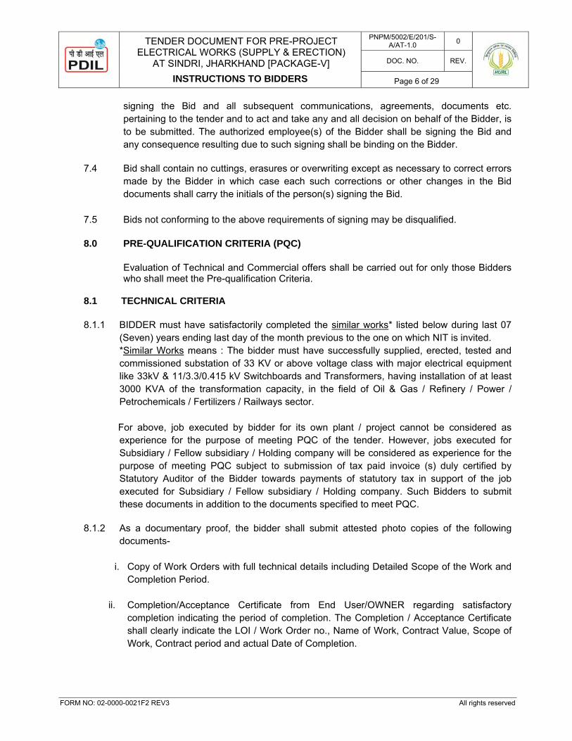
In order to afford Bidders reasonable time to take the amendment, issued prior to submission of Bids, into account in preparing their Bids, OWNER may, at its discretion, extend the deadline for the submission of Bids.
5.0 LANGUAGE OF THE BID The Bid prepared by the Bidders and all correspondence and documents relating to the
Bid exchanged by the Bidder and the CONSULTANT/ OWNER shall be written in the English language and all units shall be in Metric system. Any printed literature furnished by the Bidder may be written in another language, provided that such literature is accompanied by an English translation, in which case, for purpose of interpretation of the Bid, the English translation shall govern.
6.0 TIME SCHEDULE 6.1 Bidder shall be required to complete the WORK under the CONTRACT in accordance with
the following:
PROJECT COMPLETION DATE : 30 Months from the Effective Date of Contract. Major milestones are as follows:-
Complete Installation of Sub-station 06 Months from Effective Date of Contract Operation & Maintenance 24 Months from Completion of Sub-station
Work 6.2 The “Effective Date of Contract” shall be the date of issuance of LOI (Letter of Intent) by
the Owner. 6.3 The basic consideration and essence of the Contract
is the strict adherence to the time
schedules for performing the specified works as stipulated in the Contract. 7.0 SIGNATURE ON BIDS 7.1 The Bid must contain the name, designation and place of business of the person or
persons making the Bid and must be signed and sealed, on each page, by the Bidder with his usual signature. The names of all persons signing should also be typed or printed below the signature. The Bidder shall submit authority letter / Power of Attorney / Board Resolution in favour of the authorized signatory(s) of the Bid. The Bidder's name stated on the proposal shall be the exact legal name of the Bidder.
7.2 Bids by bodies corporate/ limited Companies must be signed with the legal name of the
Corporation/Limited Company by the President, Managing Director or by the Company Secretary or any other person or persons holding Power of Attorney for signing their Bid.
7.3 In case of a Single Bidder, Power of Attorney issued by the Board of Directors / CEO / MD / Company Secretary of the Bidder/ all partners in case of Partnership Firm / Proprietor in favor of the authorized employee(s) of the Bidder, in respect of the particular tender for
TENDER DOCUMENT FOR PRE-PROJECT ELECTRICAL WORKS (SUPPLY & ERECTION)
AT SINDRI, JHARKHAND [PACKAGE-V]
INSTRUCTIONS TO BIDDERS
PNPM/5002/E/201/S-A/AT-1.0 0
DOC. NO. REV.
Page 6 of 29
FORM NO: 02-0000-0021F2 REV3 All rights reserved
signing the Bid and all subsequent communications, agreements, documents etc. pertaining to the tender and to act and take any and all decision on behalf of the Bidder, is to be submitted. The authorized employee(s) of the Bidder shall be signing the Bid and any consequence resulting due to such signing shall be binding on the Bidder.
7.4 Bid shall contain no cuttings, erasures or overwriting except as necessary to correct errors made by the Bidder in which case each such corrections or other changes in the Bid documents shall carry the initials of the person(s) signing the Bid.
7.5 Bids not conforming to the above requirements of signing may be disqualified. 8.0 PRE-QUALIFICATION CRITERIA (PQC)
Evaluation of Technical and Commercial offers shall be carried out for only those Bidders
who shall meet the Pre-qualification Criteria. 8.1 TECHNICAL CRITERIA 8.1.1 BIDDER must have satisfactorily completed the similar works* listed below during last 07
(Seven) years ending last day of the month previous to the one on which NIT is invited. *Similar Works means : The bidder must have successfully supplied, erected, tested and commissioned substation of 33 KV or above voltage class with major electrical equipment like 33kV & 11/3.3/0.415 kV Switchboards and Transformers, having installation of at least 3000 KVA of the transformation capacity, in the field of Oil & Gas / Refinery / Power / Petrochemicals / Fertilizers / Railways sector.
For above, job executed by bidder for its own plant / project cannot be considered as experience for the purpose of meeting PQC of the tender. However, jobs executed for Subsidiary / Fellow subsidiary / Holding company will be considered as experience for the purpose of meeting PQC subject to submission of tax paid invoice (s) duly certified by Statutory Auditor of the Bidder towards payments of statutory tax in support of the job executed for Subsidiary / Fellow subsidiary / Holding company. Such Bidders to submit these documents in addition to the documents specified to meet PQC.
8.1.2 As a documentary proof, the bidder shall submit attested photo copies of the following
documents-
i. Copy of Work Orders with full technical details including Detailed Scope of the Work and Completion Period.
ii. Completion/Acceptance Certificate from End User/OWNER regarding satisfactory
completion indicating the period of completion. The Completion / Acceptance Certificate shall clearly indicate the LOI / Work Order no., Name of Work, Contract Value, Scope of Work, Contract period and actual Date of Completion.
TENDER DOCUMENT FOR PRE-PROJECT ELECTRICAL WORKS (SUPPLY & ERECTION)
AT SINDRI, JHARKHAND [PACKAGE-V]
INSTRUCTIONS TO BIDDERS
PNPM/5002/E/201/S-A/AT-1.0 0
DOC. NO. REV.
Page 7 of 29
FORM NO: 02-0000-0021F2 REV3 All rights reserved
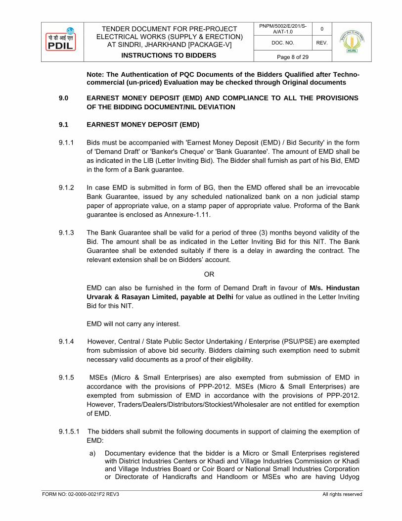
8.2 FINANCIAL CRITERIA
8.2.1 The Bidder must have executed Similar Works* during last seven (07) years ending last
day of the month previous to the one on which NIT is invited, with minimum work order (s) as per below:
One completed work with contract value not less than INR 5.46 Crore
OR Two completed works each with contract value not less than INR 3.41 Crore
OR Three completed works each with contract value not less than INR 2.73 Crore
As a documentary proof for above, the bidder shall submit attested photo copies of the documents as specified at clause no. 8.1.2 of Technical Criteria.
8.2.2 Average Annual financial turnover during three (03) financial years i.e. 2016-17, 2015-16,
and 2014-15 of the bidder meeting the requirement as per clause above experience criteria should be at least INR 2.00 Crore.
8.2.3 Net Worth of the Company should be positive during the last financial year ending 31st
March 2017. 8.2.4 The Bidder will submit Solvency certificate not more than six months old from the date of
issue of NIT from their Banker for a value not less than INR 2.75 Crore or minimum credit ratings of “A” from ICRA/CRISIL etc OR equivalent reputed institutions, OR financing / unutilized credit limits from bank of value not less than INR 2.75 Crore valid as on date of issue of ITB.
To meet the criteria (8.2.2 & 8.2.3) above, bidder shall submit Audited Annual Statements (Balance Sheet and Profit & Loss account) of the company for three (3) financial years i.e. 2016-17, 2015-16, and 2014-15.
8.3 AUTHENTICATION OF ALL DOCUMENTS SUBMITTED AGAINST PQC
All documents in support of Technical criteria of PQC to be furnished by the bidders shall necessarily be: Duly certified / attested by Notary Public with legible stamp.
In support of Financial criteria of PQC, bidder is required to submit following: Shall submit “Details of Financial capability of Bidder” in prescribed format (as per Annexure-1.21), duly signed & stamped by a Chartered Accountant. Further, a copy of Audited Annual Financial Statements submitted in bid shall be duly certified / attested by Notary Public with legible stamp.
TENDER DOCUMENT FOR PRE-PROJECT ELECTRICAL WORKS (SUPPLY & ERECTION)
AT SINDRI, JHARKHAND [PACKAGE-V]
INSTRUCTIONS TO BIDDERS
PNPM/5002/E/201/S-A/AT-1.0 0
DOC. NO. REV.
Page 8 of 29
FORM NO: 02-0000-0021F2 REV3 All rights reserved
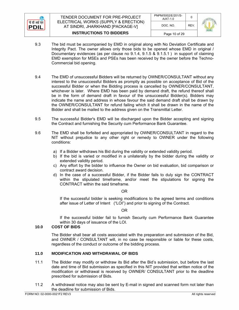
Note: The Authentication of PQC Documents of the Bidders Qualified after Techno-commercial (un-priced) Evaluation may be checked through Original documents
9.0 EARNEST MONEY DEPOSIT (EMD) AND COMPLIANCE TO ALL THE PROVISIONS
OF THE BIDDING DOCUMENT/NIL DEVIATION 9.1 EARNEST MONEY DEPOSIT (EMD) 9.1.1 Bids must be accompanied with 'Earnest Money Deposit (EMD) / Bid Security' in the form
of 'Demand Draft' or 'Banker's Cheque' or 'Bank Guarantee'. The amount of EMD shall be as indicated in the LIB (Letter Inviting Bid). The Bidder shall furnish as part of his Bid, EMD in the form of a Bank guarantee.
9.1.2 In case EMD is submitted in form of BG, then the EMD offered shall be an irrevocable
Bank Guarantee, issued by any scheduled nationalized bank on a non judicial stamp paper of appropriate value, on a stamp paper of appropriate value. Proforma of the Bank guarantee is enclosed as Annexure-1.11.
9.1.3 The Bank Guarantee shall be valid for a period of three (3) months beyond validity of the
Bid. The amount shall be as indicated in the Letter Inviting Bid for this NIT. The Bank Guarantee shall be extended suitably if there is a delay in awarding the contract. The relevant extension shall be on Bidders’ account.
OR
EMD can also be furnished in the form of Demand Draft in favour of M/s. Hindustan
Urvarak & Rasayan Limited, payable at Delhi for value as outlined in the Letter Inviting Bid for this NIT.
EMD will not carry any interest.
9.1.4 However, Central / State Public Sector Undertaking / Enterprise (PSU/PSE) are exempted
from submission of above bid security. Bidders claiming such exemption need to submit necessary valid documents as a proof of their eligibility.
9.1.5 MSEs (Micro & Small Enterprises) are also exempted from submission of EMD in
accordance with the provisions of PPP-2012. MSEs (Micro & Small Enterprises) are exempted from submission of EMD in accordance with the provisions of PPP-2012. However, Traders/Dealers/Distributors/Stockiest/Wholesaler are not entitled for exemption of EMD.
9.1.5.1 The bidders shall submit the following documents in support of claiming the exemption of EMD:
a) Documentary evidence that the bidder is a Micro or Small Enterprises registered with District Industries Centers or Khadi and Village Industries Commission or Khadi and Village Industries Board or Coir Board or National Small Industries Corporation or Directorate of Handicrafts and Handloom or MSEs who are having Udyog

TENDER DOCUMENT FOR PRE-PROJECT ELECTRICAL WORKS (SUPPLY & ERECTION)
AT SINDRI, JHARKHAND [PACKAGE-V]
INSTRUCTIONS TO BIDDERS
PNPM/5002/E/201/S-A/AT-1.0 0
DOC. NO. REV.
Page 9 of 29
FORM NO: 02-0000-0021F2 REV3 All rights reserved
Aadhaar Memorandum or any other body specified by Ministry of Micro, Small and Medium Enterprises.
b) The above document submitted by the bidder shall be duly certified (in original) by Notary or the Statutory Auditor of the bidder or a practicing Chartered Accountant (not being an employee or a Director or not having any interest in the bidder’s company/firm) where audited accounts are not mandatory as per law or duly notarized by any Notary Public in the bidder’s country.
c) If the bidder does not provide the appropriate document or any evidence to substantiate the above, then it will be presumed that they do not qualify for any preference admissible in the Public Procurement Policy, 2012.
9.2 COMPLIANCE TO ALL THE PROVISIONS OF THE BIDDING DOCUMENT / NIL
DEVIATION The Bidders are advised that while making their Bid and quoting prices, all conditions may appropriately be taken into consideration. No deviation, whatsoever, is permitted by the Owner to the provisions of Bidding Documents and its subsequent Amendment(s) / Clarification(s) / Addenda / Errata if any, issued by the Employer. Bidders are required to certify their full compliance to the complete Bidding Documents and its subsequent Amendment(s) / Clarification(s) / Addenda / Errata if any, issued by the owner by submitting the ‘No Deviation Certificate’ as per Annexure-1.3 in the tender documents. In case the Certificate as per Annexure-1.3 duly signed and stamped is not furnished, the bid shall be rejected. Acceptance of above shall be considered as Bidder's confirmation that any deviation to the Bidding Documents found anywhere in their Bid Proposal, implicit or explicit shall stand unconditionally withdrawn, without any cost implication whatsoever to owner, failing which the bid shall be rejected and bid security shall be forfeited.
9.2.3 Bidders shall submit their EMD in original// Documentary evidences in support of EMD
exemption for MSEs & PSEs, along with No Deviation Certificate and Integrity Pact, at following address.
The envelope shall be super scribed with: “ PRE-PROJECT ELECTRICAL WORKS (SUPPLY & ERECTION) AT SINDRI, JHARKHAND [PACKAGE-V] "
PROJECTS & DEVELOPMENT INDIA LTD. (A Govt. of India Enterprise) PDIL BHAWAN, A-14, SECTOR-1, NOIDA-201301, U.P., (INDIA) Kind Attention: Mr. Pawan Kumar Mishra, Project Manager EPBX No. + 91-120-2529842 / 43 / 47 / 51 / 53 / 54 Extn. 315 Fax no. + 91-120-2529801 / 91 E-mail : [email protected]
TENDER DOCUMENT FOR PRE-PROJECT ELECTRICAL WORKS (SUPPLY & ERECTION)
AT SINDRI, JHARKHAND [PACKAGE-V]
INSTRUCTIONS TO BIDDERS
PNPM/5002/E/201/S-A/AT-1.0 0
DOC. NO. REV.
Page 10 of 29
FORM NO: 02-0000-0021F2 REV3 All rights reserved
9.3 The bid must be accompanied by EMD in original along with No Deviation Certificate and Integrity Pact. The owner allows only those bids to be opened whose EMD in original / Documentary evidences (as per clause no 9.1.4, 9.1.5 & 9.1.5.1 ) in support of claiming EMD exemption for MSEs and PSEs has been received by the owner before the Techno-Commercial bid opening.
9.4 The EMD of unsuccessful Bidders will be returned by OWNER/CONSULTANT without any
interest to the unsuccessful Bidders as promptly as possible on acceptance of Bid of the successful Bidder or when the Bidding process is cancelled by OWNER/CONSULTANT, whichever is later. Where EMD has been paid by demand draft, the refund thereof shall be in the form of demand draft in favour of the unsuccessful Bidder(s). Bidders may indicate the name and address in whose favour the said demand draft shall be drawn by the OWNER/CONSULTANT for refund failing which it shall be drawn in the name of the Bidder and shall be mailed to the address given on the Transmittal Letter.
9.5 The successful Bidder's EMD will be discharged upon the Bidder accepting and signing
the Contract and furnishing the Security cum Performance Bank Guarantee. 9.6 The EMD shall be forfeited and appropriated by OWNER/CONSULTANT in regard to the
NIT without prejudice to any other right or remedy to OWNER under the following conditions:
a) If a Bidder withdraws his Bid during the validity or extended validity period. b) If the bid is varied or modified in a unilaterally by the bidder during the validity or
extended validity period. c) Any effort by the bidder to influence the Owner on bid evaluation, bid comparison or
contract award decision. d) In the case of a successful Bidder, if the Bidder fails to duly sign the CONTRACT
within the stipulated timeframe, and/or meet the stipulations for signing the CONTRACT within the said timeframe.
OR
If the successful bidder is seeking modifications to the agreed terms and conditions after issue of Letter of Intent (“LOI”) and prior to signing of the Contract.
OR
If the successful bidder fail to furnish Security cum Performance Bank Guarantee within 30 days of issuance of the LOI.
10.0 COST OF BIDS
The Bidder shall bear all costs associated with the preparation and submission of the Bid, and OWNER / CONSULTANT will, in no case be responsible or liable for these costs, regardless of the conduct or outcome of the bidding process.
11.0 MODIFICATION AND WITHDRAWAL OF BIDS 11.1 The Bidder may modify or withdraw its Bid after the Bid’s submission, but before the last
date and time of Bid submission as specified in this NIT provided that written notice of the modification or withdrawal is received by OWNER/ CONSULTANT prior to the deadline prescribed for submission of Bids.
11.2 A withdrawal notice may also be sent by E-mail in signed and scanned form not later than
the deadline for submission of Bids.
TENDER DOCUMENT FOR PRE-PROJECT ELECTRICAL WORKS (SUPPLY & ERECTION)
AT SINDRI, JHARKHAND [PACKAGE-V]
INSTRUCTIONS TO BIDDERS
PNPM/5002/E/201/S-A/AT-1.0 0
DOC. NO. REV.
Page 11 of 29
FORM NO: 02-0000-0021F2 REV3 All rights reserved
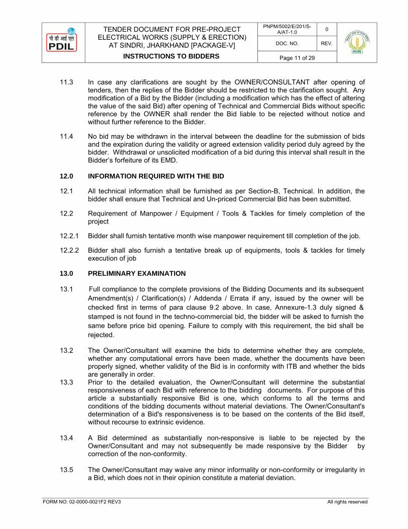
11.3 In case any clarifications are sought by the OWNER/CONSULTANT after opening of
tenders, then the replies of the Bidder should be restricted to the clarification sought. Any modification of a Bid by the Bidder (including a modification which has the effect of altering the value of the said Bid) after opening of Technical and Commercial Bids without specific reference by the OWNER shall render the Bid liable to be rejected without notice and without further reference to the Bidder.
11.4 No bid may be withdrawn in the interval between the deadline for the submission of bids
and the expiration during the validity or agreed extension validity period duly agreed by the bidder. Withdrawal or unsolicited modification of a bid during this interval shall result in the Bidder’s forfeiture of its EMD.
12.0 INFORMATION REQUIRED WITH THE BID 12.1 All technical information shall be furnished as per Section-B, Technical. In addition, the
bidder shall ensure that Technical and Un-priced Commercial Bid has been submitted. 12.2 Requirement of Manpower / Equipment / Tools & Tackles for timely completion of the
project 12.2.1 Bidder shall furnish tentative month wise manpower requirement till completion of the job. 12.2.2 Bidder shall also furnish a tentative break up of equipments, tools & tackles for timely
execution of job 13.0 PRELIMINARY EXAMINATION 13.1 Full compliance to the complete provisions of the Bidding Documents and its subsequent
Amendment(s) / Clarification(s) / Addenda / Errata if any, issued by the owner will be checked first in terms of para clause 9.2 above. In case, Annexure-1.3 duly signed & stamped is not found in the techno-commercial bid, the bidder will be asked to furnish the same before price bid opening. Failure to comply with this requirement, the bid shall be rejected.
13.2 The Owner/Consultant will examine the bids to determine whether they are complete,
whether any computational errors have been made, whether the documents have been properly signed, whether validity of the Bid is in conformity with ITB and whether the bids are generally in order.
13.3 Prior to the detailed evaluation, the Owner/Consultant will determine the substantial responsiveness of each Bid with reference to the bidding documents. For purpose of this article a substantially responsive Bid is one, which conforms to all the terms and conditions of the bidding documents without material deviations. The Owner/Consultant's determination of a Bid's responsiveness is to be based on the contents of the Bid itself, without recourse to extrinsic evidence.
13.4 A Bid determined as substantially non-responsive is liable to be rejected by the
Owner/Consultant and may not subsequently be made responsive by the Bidder by correction of the non-conformity.
13.5 The Owner/Consultant may waive any minor informality or non-conformity or irregularity in
a Bid, which does not in their opinion constitute a material deviation.
TENDER DOCUMENT FOR PRE-PROJECT ELECTRICAL WORKS (SUPPLY & ERECTION)
AT SINDRI, JHARKHAND [PACKAGE-V]
INSTRUCTIONS TO BIDDERS
PNPM/5002/E/201/S-A/AT-1.0 0
DOC. NO. REV.
Page 12 of 29
FORM NO: 02-0000-0021F2 REV3 All rights reserved
13.6 Under two stage bidding system, after a preliminary screening based on both technical and un-priced commercial evaluation, Bidders will be short-listed. In the event that any clarifications are required, then such clarifications shall be obtained from such short listed bidders only. Based on the clarifications, the technically acceptable Bidders shall be asked to submit the revised price.
14.0 LOCAL CONDITIONS 14.1 It will be imperative on each Bidder to fully make aware himself of all local conditions and
factors which may have any effect on the execution of the works covered under these specifications and documents. Bidder shall inspect the site, examine and obtain at its cost and responsibility, all information required and satisfy himself regarding all matters and things such as access to site, communications, transport, right of way, the type and number of equipment and facilities required for the work, availability of local labour, materials and their rates, local working conditions, weather, flood levels, sub-soil conditions, natural drainage, and all information that may be necessary for preparing its Bid, performance of work and other obligations and related matters. By submitting the Bid the Bidder shall be deemed to have acknowledged and agreed that ignorance of the site and other said conditions shall not be basis for any claim for compensation or extension of time or loss of profits etc. and the OWNER shall not be liable on account thereof in any manner whatsoever to the Bidder or any person claiming through or under the Bidder.
14.2 Bidders must before submission of their Bids, acquaint themselves with all applicable
regulatory and other legal requirements pertaining to insurance and health, safety and environment requirement in INDIA and rules related to work permit and visa requirements in INDIA or in any way or manner affecting the performance of Scope of Work, the Contractor and the Plant operation and performance including social security, safety, pollution control, permits, licenses, and the other statutory requirements and regulations. The submission of a Bid by the Bidder will be construed as evidence that such an examination was made and the Bidder shall not raise at any time later any claims/disputes against the OWNER and the OWNER shall not be liable for the same in any manner whatsoever.
14.3 Deleted 14.4 The Owner shall not entertain any request for clarification from the bidder, regarding such
local conditions. 14.5 The Bidder shall be deemed to have prepared the Bid on the basis of its independent
judgment and to have made all necessary allowances and provisions to ensure that the PROJECT will meet all technical specification prescribed hereunder in the tender document and will be entirely suitable for the purpose for which it is intended. Accordingly, at the time of submission the Bid Price will, without extra price and/or extension of time, be held to include everything implicitly or otherwise required or necessary for the proper and timely completion of the WORK in accordance with the CONTRACT. Further, in case of any contract awarded under these specifications and documents, neither any change in the time schedule of the Contract nor any financial adjustments arising thereof shall be permitted by the Owner, which are based on the lack of such clear information or its effect on the cost of the works to the Bidder.
14.6 Visit to site at BIDDER’s cost and expense.
TENDER DOCUMENT FOR PRE-PROJECT ELECTRICAL WORKS (SUPPLY & ERECTION)
AT SINDRI, JHARKHAND [PACKAGE-V]
INSTRUCTIONS TO BIDDERS
PNPM/5002/E/201/S-A/AT-1.0 0
DOC. NO. REV.
Page 13 of 29
FORM NO: 02-0000-0021F2 REV3 All rights reserved
15.0 PRICE BASIS & CURRENCY OF BIDS 15.1 The Bidder shall quote in Indian Rupees only. 15.2 The price/rate to be quoted by the Contractor shall be fixed and firm shall be valid until
completion of the Contract to be executed with the successful Bidder pursuant hereto and shall not be subject to variation/escalation on any account except as otherwise specifically provided in the Contract documents.
15.3 Site is located at Sindri, Jharkhand, India and the bidder are required to check & confirm
before bidding for applicability of all taxes & duties for the procurement of supply and service by them for the execution of contract.
15.4 The Bidders shall quote in their proposals, the firm price for the entire scope of work as
per Schedule of Prices, (Refer Part-III of Section-B, Technical), inclusive of all taxes, duties, levies etc. except GST as applicable. GST amount will be quoted separately which will be paid at actual by the owner limited to the GST amount indicated by the bidder in their bid.
15.5 All bank charges of bidders bankers shall be to the Bidder’s account and all Bank charges of Owner's bankers shall be to Owner’s account.
15.6 Income Tax, or any other tax and surcharge as applicable shall be deducted at source
from the bills of the contractor and a certificate to that effect shall be issued by the Owner. 16.0 CONSORTIUM BIDS
Joint Venture / Consortium Bids are not acceptable. 17.0 NUMBER OF BIDS 17.1 A bidder shall on no account submit more than one bid either directly or indirectly. 17.2 A bidder shall be deemed to have submitted an indirect bid if a subsidiary of the bidder is
also a direct or indirect bidder in an independent bid or if the bidder or its subsidiary has with its consent been indicated as a sub-contractor in any other bid or even if not so indicated has entered into any arrangement (whether disclosed or undisclosed) with any other bidder or with a sub-contractor of that bidder for the performance of any work for that other bidder upon an award of the work to that other bidder.
17.3 If a bidder makes more than one bid and/or directly or indirectly participates in another bid as contemplated under 17.2 above, all the bids of the bidder, including the bid of the bidder in whose bid the first named bidder has directly or indirectly participated, may be considered as cartel bids and may be rejected. If the factum of such bid(s) is discovered after the notification of award, the resultant contract shall be liable to be terminated pursuant to the provisions for termination contained in the General Conditions of Contract.
18.0 CONFIDENTIALITY OF DOCUMENTS Bidders shall treat the bidding documents and contents therein as strictly confidential. 19.0 TAXES AND DUTIES
TENDER DOCUMENT FOR PRE-PROJECT ELECTRICAL WORKS (SUPPLY & ERECTION)
AT SINDRI, JHARKHAND [PACKAGE-V]
INSTRUCTIONS TO BIDDERS
PNPM/5002/E/201/S-A/AT-1.0 0
DOC. NO. REV.
Page 14 of 29
FORM NO: 02-0000-0021F2 REV3 All rights reserved
19.1 The Prices/Rates shall include all taxes & duties, levies etc. including but not limited to custom duty, personnel and corporate tax, except GST. GST amount will be paid extra at actual by the owner limited to the GST amount quoted by the bidder in their bid.
19.2 Bidders are required to ascertain themselves the prevailing rates of applicable taxes &
duties including income tax rates as applicable on the scheduled date of submission of price bids and Owner would not undertake any responsibility whatsoever in this regard. However, due to any subsequent change in law, liability of the Owner as regards to payment of duties and taxes would be governed by Clause 39.0 of Special Conditions of Contract on subsequent legislation.
19.3 Please note that the responsibility of payment of above taxes thereupon lies with the
Service Provider only. Contractor providing taxable service shall issue an Invoice as per the law, a Bill or as the case may be, a Challan which is signed, serially numbered and in accordance with GST rules. The invoice shall also contain the following:
(a) Name, Address & GST Registration No. of such Person/Contractor (b) Name & Address of the Person/Contractor receiving Taxable Service (c) Description, Classification & Value of Taxable Service provided like HSN/SAC Code. (d) GST Amount & Cess thereupon, if any. Payments to Service Provider for claiming GST amount will be made provided the above formalities are fulfilled. Further, OWNER may seek copies of challan and certificate from Chartered Accountant for deposit / submission of Return of GST thereupon collected from Owner. Any changes in statutory rules and regulations under GST regime shall be followed by Contractor. Refer Annexure-1.20 of Section-A (Commercial) for General Guidelines for Goods & Service Tax (GST)
20.0 DETERMINATION OF BID’S RESPONSIVENESS 20.1 The Owner's determination of a bid's responsiveness is to be based on the contents of the
bid itself without recourse to extrinsic evidence. If a bid is not substantially responsive, it will be rejected by the Owner, and may not subsequently be made responsive by the Bidder by correction of the nonconformity.
20.2 It is important that Bidder clearly demonstrates his experience and capability, giving
OWNER/CONSULTANT a high level of confidence that if awarded, the Bidder will be able to perform the works within the stipulated Time Schedule and quoted rate/price and meeting all other requirements listed in the Bidding document.
20.3 Bidder is requested to furnish the complete and correct information required for evaluation
of his Bid. If the information with regard to resources and concurrent commitments or any other information/documentation forming basis of evaluation is found incomplete/incorrect, the same may be considered as adequate ground for rejection of the Bid.
20.3 Examination of bids and determination of responsiveness 20.3.1 The owner’s determination of bid’s responsiveness is based on the content of the bid only.
Prior to the detailed evaluation of Bids, the Owner will determine whether each Bid:-
TENDER DOCUMENT FOR PRE-PROJECT ELECTRICAL WORKS (SUPPLY & ERECTION)
AT SINDRI, JHARKHAND [PACKAGE-V]
INSTRUCTIONS TO BIDDERS
PNPM/5002/E/201/S-A/AT-1.0 0
DOC. NO. REV.
Page 15 of 29
FORM NO: 02-0000-0021F2 REV3 All rights reserved
(a) Meets the "Pre-Qualification Criteria" of the Bidding Documents; (b) Has been properly signed; (c) Is accompanied by the required 'Earnest Money; (d) Is substantially responsive to the requirements of the Bidding Documents; and (e) Provides any clarification and/or substantiation that the Owner may require to
determine responsiveness pursuant to Clause-20.3.2 of this ITB 20.3.2 A substantially responsive Bid is one which conforms to all the terms, conditions and
specifications of the Bidding Documents without material deviations or reservations or omissions for this purpose Owner defines the foregoing terms below:-
(a) “Deviation” is departure from the requirement specified in the tender documents. (b) “Reservation” is the setting of limiting conditions or withholding from complete
acceptance of the requirement in the tender documents. (c) “Omission” is the failure to submit part or all of the information or documentation
required in the tender document. 20.3.3 A material deviation, reservation or omission is one that,
(a) If accepted would,
i) Affect in any substantial way the scope, quality, or performance of the job as specified in tender documents.
ii) Limit, in any substantial way, inconsistent with the Tender Document, the Owner’s rights or the tenderer‟s obligations under the proposed Contract.
b) If rectified, would unfairly affect the competitive position of other bidders presenting substantially responsive bids.
20.3.4 The Owner shall examine all aspects of the bid to confirm that all requirements have been
met without any material deviation, reservation or omission. 20.3.5 If a Bid is not substantially responsive, it may be rejected by the Owner and may not
subsequently be made responsive by correction or withdrawal of the material deviation, reservation or omission.
21.0 SUBMISSION OF BIDS
21.1 The Bid shall be submitted in electronic format (through CPP portal) as per time schedule
mentioned in the Letter Inviting Bid.
The Bidder shall submit Bid Security / EMD in physical form only/Documentary evidences in support of EMD exemption for MSEs & PSEs. at the address mentioned at Clause 9.0 of Instruction to Bidders
21.2 Instruction for Online Submission of Bid Instructions to the Bidders to submit the bids online through the Central Public
Procurement Portal for e-Procurement at https://eprocure.gov.in/eprocure/app
TENDER DOCUMENT FOR PRE-PROJECT ELECTRICAL WORKS (SUPPLY & ERECTION)
AT SINDRI, JHARKHAND [PACKAGE-V]
INSTRUCTIONS TO BIDDERS
PNPM/5002/E/201/S-A/AT-1.0 0
DOC. NO. REV.
Page 16 of 29
FORM NO: 02-0000-0021F2 REV3 All rights reserved
1) Possession of valid Digital Signature Certificate (DSC) and enrolment/registration of the contractors/bidders on the e-procurement / e-tender portal is a prerequisite for e-tendering.
2) Bidder should do the enrolment in the e-procurement site using the “Click here to
Enroll” option available on the home page. Portal enrolment is generally free of charge. During enrolment/registration, the bidders should provide the correct/true information including valid email id. All the correspondence shall be made directly with the contractors/bidders through email id provided.
3) Bidder need to login to the site thro’ their user ID/ password chosen during
enrolment/registration. 4) Then the Digital Signature Certificate (Class II or Class III Certificates with signing
key usage) issued by SIFY / TCS / nCode / eMudra or any Certifying Authority recognized by CCA India on eToken / SmartCard, should be registered.
5) The DSC that is registered only should be used by the bidder and should ensure
safety of the same. 6) Bidder may go through the NIT / tenders published on the site and download the
required NIT documents/schedules for the tenders he/she is interested. 7) After downloading / getting the NIT/ Tender document/schedules, the Bidder should
go thro’ them carefully and then submit the documents as asked, otherwise bid will be rejected.
8) If there are any clarifications, this may be obtained online thro’ the tender site, or
thro’ the contact details. Bidder should take into account the corrigendum published before submitting the bids online.
9) Bidder then logs in to the site through the secured log in by giving the user id/
password chosen during enrolment/registration and then by giving the password of the e-Token / Smart Card to access DSC.
10) Bidder selects the tender which he/she is interested in by using the search option &
then moves it to the ‘my tenders’ folder. 11) From my tender folder, he / she selects the tender to view all the details indicated. 12) It is construed that the bidder has read all the terms and conditions before submitting
their offer. Bidder should go through the tender schedules carefully and upload the documents as asked otherwise, the bid will be rejected.
13) Bidder, in advance, should get ready the bid documents to be submitted as indicated
in the tender document/schedule and generally, they can be in PDF/xls/rar/zip/dwf formats. If there is more than one document, they can be clubbed together and can be provided in the requested format. Each document to be uploaded through online for the tenders should be less than 2 MB. If any document is more than 2MB, it can be reduced through zip/rar and the same can be uploaded, if permitted. Bidders Bid documents may be scanned with 100 dpi with black and white option. However of the file size is less than 1 MB the transaction uploading time will be very fast.
TENDER DOCUMENT FOR PRE-PROJECT ELECTRICAL WORKS (SUPPLY & ERECTION)
AT SINDRI, JHARKHAND [PACKAGE-V]
INSTRUCTIONS TO BIDDERS
PNPM/5002/E/201/S-A/AT-1.0 0
DOC. NO. REV.
Page 17 of 29
FORM NO: 02-0000-0021F2 REV3 All rights reserved
14) If there are any clarifications, this may be obtained through the site, or during the pre-bid meeting if any. Bidder should take into account the corrigendum published from time to time before submitting the online bids.
15) The Bidders can update well in advance, the documents such as certificates, annual
report details etc., under My Space option and these can be selected as per tender requirements and then send along with bid documents during bid submission. This will facilitate the bid submission process faster by reducing upload time of bids.
16) Bidder should submit the EMD as specified in the tender. The original should be
posted/couriered/given in person to the Tender Inviting Authority, within the bid submission due date & time for the tender. Scanned copy of the instrument should be uploaded as part of the offer.
17) While submitting the bids online, the bidder reads the terms & conditions and
accepts the same to proceed further to submit the bid packets. 18) The bidder has to select the payment option as offline to pay the Tender FEE/ EMD
as applicable and enter details of the instruments. 19) The details of the DD/any other accepted instrument, physically sent, should tally
with the details available in the scanned copy and the data entered during bid submission time. Otherwise submitted bid will not be acceptable.
20) The bidder has to digitally sign and upload the required bid documents one by one
as indicated. Bidders to note that the very act of using DSC for downloading the bids and uploading their offers shall be deemed to be a confirmation that they have read all sections and pages of the bid document including General conditions of contract without any exception and have understood the entire document and are clear about the requirements of the tender requirements.
21) The bidder has to upload the relevant files required as indicated in the cover content.
In case of any irrelevant files, the bid will be rejected. 22) If the price bid format is provided in a spread sheet file like BoQ_xxxx.xls, the rate
offered should be entered in the allotted space only and uploaded after filling the relevant columns. The Price Bid / BOQ template must not be modified/ replaced by the bidder; else the bid submitted is liable to be rejected for this tender.
23) The bidders are requested to submit the bids through online e-tendering system to
the Tender Inviting Authority (TIA) well before the bid submission end date & time (as per Server System Clock). The TIA will not be held responsible for any sort of delay or the difficulties faced during the submission of bids online by the bidders at the eleventh hour.
24) After the bid submission (i.e. after Clicking “Freeze Bid Submission” in the portal),
the acknowledgement number, given by the system should be printed by the bidder and kept as a record of evidence for online submission of bid for the particular tender and will also act as an entry pass to participate in the bid opening date.
25) The time settings fixed in the server side & displayed at the top of the tender site, will
be valid for all actions of requesting, bid submission, bid opening etc., in the e-tender system. The bidders should follow this time during bid submission.
TENDER DOCUMENT FOR PRE-PROJECT ELECTRICAL WORKS (SUPPLY & ERECTION)
AT SINDRI, JHARKHAND [PACKAGE-V]
INSTRUCTIONS TO BIDDERS
PNPM/5002/E/201/S-A/AT-1.0 0
DOC. NO. REV.
Page 18 of 29
FORM NO: 02-0000-0021F2 REV3 All rights reserved
26) All the data being entered by the bidders would be encrypted using PKI encryption
techniques to ensure the secrecy of the data. The data entered will not viewable by unauthorized persons during bid submission & not be viewable by any one until the time of bid opening.
27) Any bid document that is uploaded to the server is subjected to symmetric encryption
using a system generated symmetric key. Further this key is subjected to asymmetric encryption using buyers/bid openers public keys. Overall, the uploaded tender documents become readable only after the tender opening by the authorized bid openers.
28) The confidentiality of the bids is maintained since the secured Socket Layer 128 bit
encryption technology is used. Data storage encryption of sensitive fields is done. 29) The bidder should logout of the tendering system using the normal logout option
available at the top right hand corner and not by selecting the (X) exit option in the browser.
Note: A bidder shall submit only one bid in the same bidding process. A Bidder who submits more than one bid will cause all their bids disqualified in the said bidding process.
21.3 The Bidder is expected to examine all instructions, forms, terms and conditions in the NIT.
The NIT together with all its attachments thereto, shall be considered to be read, understood and accepted by the Bidders. Failure to furnish all information required or submission of a Bid not responsive to the NIT in every respect will be at the Bidder’s risk and may result in the rejection of the Bid.
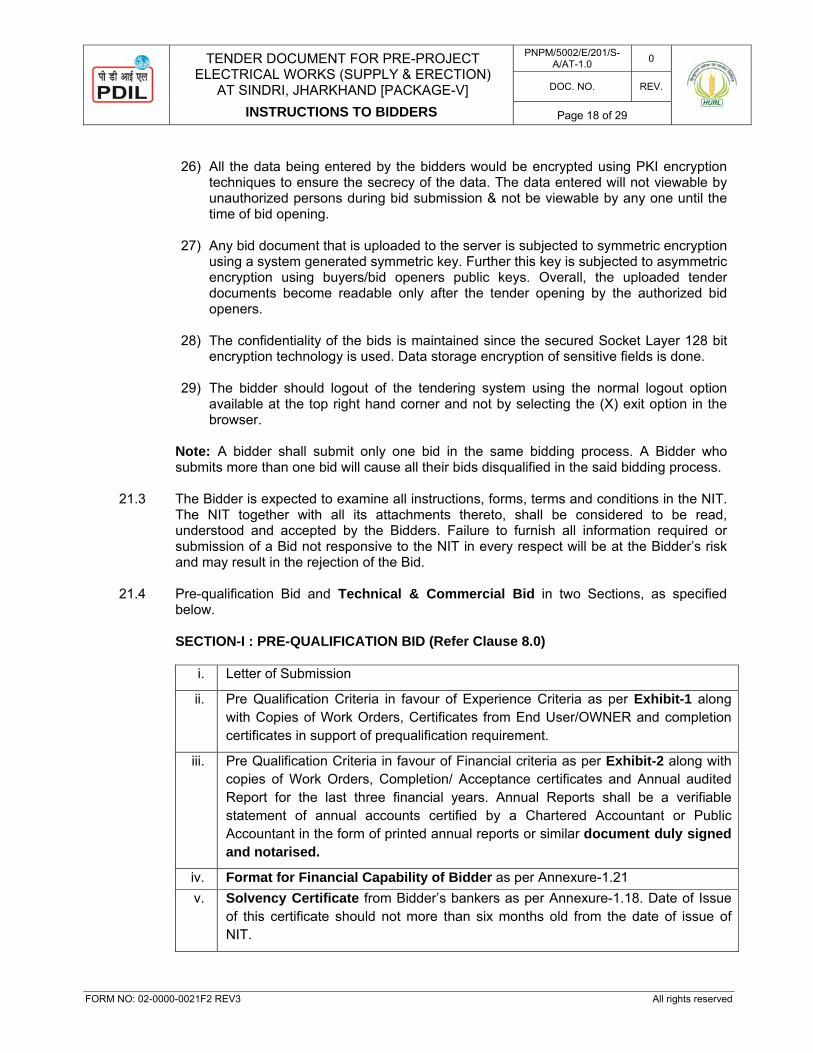
21.4 Pre-qualification Bid and Technical & Commercial Bid in two Sections, as specified
below. SECTION-I : PRE-QUALIFICATION BID (Refer Clause 8.0)
i. Letter of Submission
ii. Pre Qualification Criteria in favour of Experience Criteria as per Exhibit-1 along with Copies of Work Orders, Certificates from End User/OWNER and completion certificates in support of prequalification requirement.
iii. Pre Qualification Criteria in favour of Financial criteria as per Exhibit-2 along with copies of Work Orders, Completion/ Acceptance certificates and Annual audited Report for the last three financial years. Annual Reports shall be a verifiable statement of annual accounts certified by a Chartered Accountant or Public Accountant in the form of printed annual reports or similar document duly signed and notarised.
iv. Format for Financial Capability of Bidder as per Annexure-1.21 v. Solvency Certificate from Bidder’s bankers as per Annexure-1.18. Date of Issue
of this certificate should not more than six months old from the date of issue of NIT.
TENDER DOCUMENT FOR PRE-PROJECT ELECTRICAL WORKS (SUPPLY & ERECTION)
AT SINDRI, JHARKHAND [PACKAGE-V]
INSTRUCTIONS TO BIDDERS
PNPM/5002/E/201/S-A/AT-1.0 0
DOC. NO. REV.
Page 19 of 29
FORM NO: 02-0000-0021F2 REV3 All rights reserved
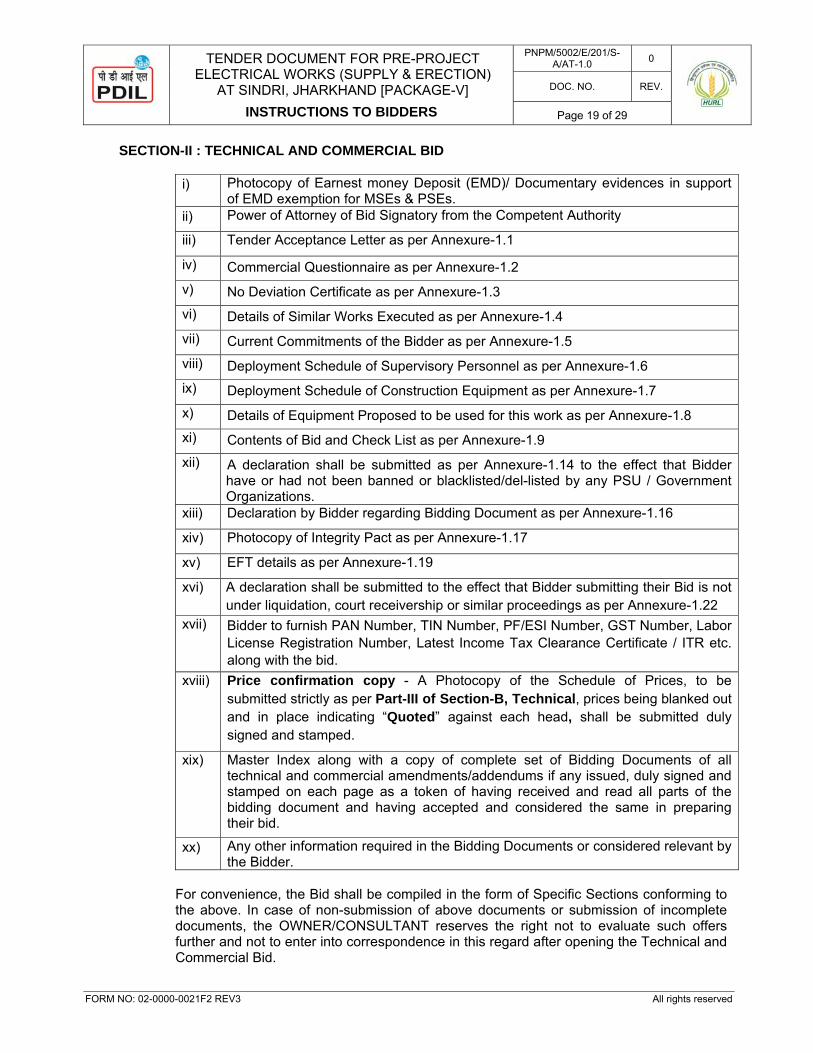
SECTION-II : TECHNICAL AND COMMERCIAL BID
i) Photocopy of Earnest money Deposit (EMD)/ Documentary evidences in support of EMD exemption for MSEs & PSEs.
ii) Power of Attorney of Bid Signatory from the Competent Authority
iii) Tender Acceptance Letter as per Annexure-1.1
iv) Commercial Questionnaire as per Annexure-1.2 v) No Deviation Certificate as per Annexure-1.3 vi) Details of Similar Works Executed as per Annexure-1.4 vii) Current Commitments of the Bidder as per Annexure-1.5 viii) Deployment Schedule of Supervisory Personnel as per Annexure-1.6 ix) Deployment Schedule of Construction Equipment as per Annexure-1.7 x) Details of Equipment Proposed to be used for this work as per Annexure-1.8 xi) Contents of Bid and Check List as per Annexure-1.9 xii) A declaration shall be submitted as per Annexure-1.14 to the effect that Bidder
have or had not been banned or blacklisted/del-listed by any PSU / Government Organizations.
xiii) Declaration by Bidder regarding Bidding Document as per Annexure-1.16
xiv) Photocopy of Integrity Pact as per Annexure-1.17
xv) EFT details as per Annexure-1.19
xvi) A declaration shall be submitted to the effect that Bidder submitting their Bid is not under liquidation, court receivership or similar proceedings as per Annexure-1.22
xvii) Bidder to furnish PAN Number, TIN Number, PF/ESI Number, GST Number, Labor License Registration Number, Latest Income Tax Clearance Certificate / ITR etc. along with the bid.
xviii) Price confirmation copy - A Photocopy of the Schedule of Prices, to be submitted strictly as per Part-III of Section-B, Technical, prices being blanked out and in place indicating “Quoted” against each head, shall be submitted duly signed and stamped.
xix) Master Index along with a copy of complete set of Bidding Documents of all technical and commercial amendments/addendums if any issued, duly signed and stamped on each page as a token of having received and read all parts of the bidding document and having accepted and considered the same in preparing their bid.
xx) Any other information required in the Bidding Documents or considered relevant by the Bidder.
For convenience, the Bid shall be compiled in the form of Specific Sections conforming to the above. In case of non-submission of above documents or submission of incomplete documents, the OWNER/CONSULTANT reserves the right not to evaluate such offers further and not to enter into correspondence in this regard after opening the Technical and Commercial Bid.
TENDER DOCUMENT FOR PRE-PROJECT ELECTRICAL WORKS (SUPPLY & ERECTION)
AT SINDRI, JHARKHAND [PACKAGE-V]
INSTRUCTIONS TO BIDDERS
PNPM/5002/E/201/S-A/AT-1.0 0
DOC. NO. REV.
Page 20 of 29
FORM NO: 02-0000-0021F2 REV3 All rights reserved
21.5 PRICED BID 21.5.1 Priced Bid shall consist of in the following manner:
(i) Preamble to Price Bid. (ii) Priced Bid, duly filled in and completed in all respects, as per Part-III of Section-B,
Technical given in the Bidding Documents. 21.5.2 Priced Bid shall be submitted duly signed and stamped on each page. This part shall not
contain any condition whatsoever failing which the Bids shall be liable to be rejected. In case of any correction, the bidder shall put its signature and its stamp. Eraser fluid will not be allowed for making any correction.
If the bidder fails to quote for any item (other than Operation & Maintenance item) in the price bid i.e. Part-A, B & C of the Schedule of Rates (SOR), it will be implied that such item is included elsewhere in the quoted prices. However, the bid will be rejected in case the bidder does not quote the Operation and Maintenance item i.e. Part-D of the Schedule of Rates (SOR). Also, wherever bidder has indicated “Not Applicable” / “Nil” and the same is required during execution of the contract it will be considered as included in the price. Further, if the bidder does not quote GST in the price schedule/SOR by indicating ‘Nil’ / ‘Not applicable’/ ‘NA’ / ‘kept the space blank’, then GST amount payable by the contractor to the concerned authorities is deemed to have been included in their quoted price and no payment towards GST shall be made by the owner.
21.5.3 Prices must be strictly filled in format for “Schedule of Rates as per Part-III of Section-B,
Technical” enclosed as part of bidding document. If quoted in separate typed sheets and any variation in description, unit is noticed, the bid is liable to be rejected. In any case Bidder shall be presumed to have quoted against the description of work and the same shall be binding on the Bidder.
21.6 The Priced Bid shall also indicate total prices in figures as well as in words. The prices
should be strictly quoted as specified in Part-III of Section-B, Technical otherwise the Bid may be rejected. The priced Bid containing any comments, remarks, conditions deviations etc, which is not indicated in the Technical and Commercial Bid, is liable to be rejected.
22.0 DEADLINE FOR SUBMISSION OF BIDS: 22.1 Bids must be submitted not later than the time and date as specified in the Letter inviting
Bid. 22.2 The OWNER/ CONSULTANT may extend this deadline for the submission of Bids by
amending the NIT documents in accordance with Clause No. 4.0 above. In such case all rights and obligations of the OWNER and Bidders under this NIT shall be subject to the extended deadline.
22.3 Any bid received after the deadline specified in the NIT or as extended shall be liable to be
rejected.
TENDER DOCUMENT FOR PRE-PROJECT ELECTRICAL WORKS (SUPPLY & ERECTION)
AT SINDRI, JHARKHAND [PACKAGE-V]
INSTRUCTIONS TO BIDDERS
PNPM/5002/E/201/S-A/AT-1.0 0
DOC. NO. REV.
Page 21 of 29
FORM NO: 02-0000-0021F2 REV3 All rights reserved
23.0 OPENING OF BIDS 23.1 OWNER /CONSULTANT will open Bids in the presence of Bidder’s representatives who
choose to attend at Date and time specified on cover page of NIT or as informed by OWNER / CONSULTANT. The Bidder’s representative(s) present during the Bids opening shall sign a Bid opening record sheet evidencing their attendance.
23.2 The Bidder’s name, modifications, Bid withdrawal and such other details, as the OWNER /
CONSULTANT at its discretion may consider appropriate, will be announced during Bids opening. The owner allow only those bids to be opened whose EMD in original/Documentary evidences in support of EMD exemption for MSEs & PSEs has been received by the owner before the Techno-Commercial bid opening..
23.3 The Bids shall be opened and evaluated in two stages: 23.3.1 STAGE-I: OPENING & REVIEW OF EMD, PRE-QUALIFICATION BID, TECHNICAL
AND COMMERCIAL BIDS On the date of Public Bid opening as indicated on the Letter Inviting Bid of this NIT, cover
containing EMD shall be opened and reviewed.
The OWNER / CONSULTANT will review the Bank Guarantee (BG) submitted by Bidder against EMD, with respect to:
a. its value, b. validity & c. issuing Bank. d. the format attached with the tender document.
In case, the Bidder has not submitted the EMD or the BG submitted by the Bidder is not as
per the requirement of NIT with respect to the above mentioned parameters, the Bids submitted by them may be rejected.
If the EMD submitted by the Bidder is found to be in order with respect to above
mentioned parameters but if there is a minor deviation with respect to the format enclosed with the NIT, the OWNER /CONSULTANT may at its discretion inform the Bidder who shall have to rectify the same before the date of opening of the Price Bid. In case the Bidder fails to rectify the EMD, its Bids will be rejected and the Bidder will be informed to take back its Bid, including the Price Bid.
Thereafter, OWNER / CONSULTANT will open, Pre-qualification bid, Technical and Commercial Bids of those Bidders, whose EMD is found to be in order as described here above.
OWNER / CONSULTANT will first review Pre-qualification requirement. Technical and
Commercial Bids shall be evaluated only for those bidders whose bid is found to be Pre-qualified based on the Pre-qualification Criteria.
The owner, at its discretion, may hold post bid discussions with any one or all the bidders
at a mutually suitable date & time. However, it will not be construed from invitation/ holding of post bid discussions that the bidders have been considered eligible for opening of their Price Bid. The discussion will cover all the aspects of bidder's offer in the Techno-commercial proposal

TENDER DOCUMENT FOR PRE-PROJECT ELECTRICAL WORKS (SUPPLY & ERECTION)
AT SINDRI, JHARKHAND [PACKAGE-V]
INSTRUCTIONS TO BIDDERS
PNPM/5002/E/201/S-A/AT-1.0 0
DOC. NO. REV.
Page 22 of 29
FORM NO: 02-0000-0021F2 REV3 All rights reserved
23.3.2 STAGE – II: OPENING OF PRICE BID
Before opening the Priced Bid of the technically and commercially acceptable Bidders, if required, a meeting with the Bidders shall be arranged. Date and Venue of such meeting shall be informed at the appropriate time. The date of the opening of the Price Bid shall be intimated to technically and commercially acceptable Bidders. The price bids of such shortlisted Bidders will be opened in the presence of Bidder’s representative who chooses to attend, on the date and time to be intimated. The bidder’s name, bid price and such other details as the OWNER at its discretion may consider appropriate, will be announced at the opening of price bids. The evaluation of the priced Bids shall be done as described under Clause No. 30.0 of the ITB.
23.3.3 If the Bids as judged by the OWNER are unresponsive, the NIT may be declared void and
a new procedure for selection of CONTRACTOR as deemed appropriate by OWNER may be adopted.
24.0 CORRECTION OF ERRORS
Bids determined to be substantially responsive will be checked by the Owner / Consultant for any arithmetic errors. Errors will be corrected by the Owner / Consultant as follows:
(i) When there is a difference between the rates in figures and words, the rate which
corresponds to the amount worked out by the Bidder (by multiplying the quantity and rate) shall be taken as correct.
(ii) When the rate quoted by the Bidder in figures and words tallies but the amount is
incorrect, the rate quoted by the contractor shall be taken as correct and not the amount and the amount shall be re-calculated/ corrected accordingly.
(iii) When it is not possible to ascertain the correct rate, in the manner prescribed above,
the rate as quoted in words shall be adopted and the amount worked out, for comparison purposes.
(iv) All errors in totaling in the amount column and in carrying forward totals shall be
corrected.
The amount stated in the Bid will be adjusted by the Owner / Consultant in accordance with the above procedure for the correction of errors. If the Bidder does not accept the corrected amount of Bid, its Bid will be rejected, and the EMD shall be forfeited.
25.0 POLICY FOR BID UNDER CONSIDERATION Bids shall be deemed to be "Under Consideration" immediately after they are opened and
until such time that the official intimation of award / rejection is made by the OWNER / CONSULTANT to the Bidders. While the bids are under consideration, bidders and/or their representatives or other interested parties are advised to refrain from contacting by any means, the OWNER / CONSULTANT and/or his employees / representatives on matters related to the bids under consideration.

TENDER DOCUMENT FOR PRE-PROJECT ELECTRICAL WORKS (SUPPLY & ERECTION)
AT SINDRI, JHARKHAND [PACKAGE-V]
INSTRUCTIONS TO BIDDERS
PNPM/5002/E/201/S-A/AT-1.0 0
DOC. NO. REV.
Page 23 of 29
FORM NO: 02-0000-0021F2 REV3 All rights reserved
The OWNER / CONSULTANT, if necessary will obtain clarifications on the bids by requesting for such information from any or all the Bidders, either in writing or through personnel contact as may be necessary. The Bidder will not be permitted to change the substance of the bid after the bid had been opened.
26.0 DISCUSSIONS WITH BIDDERS DURING TECHNO- COMERCIAL EVALUATION
After opening of the Bids, to assist in the examination, evaluation and comparison of Bids, OWNER / CONSULTANT may, at its discretion, ask the Bidder for clarification on its Bid. The request for such clarification and the response shall be in writing either through fax or email. Further OWNER / CONSULTANT may ask BIDDER to visit OWNER's/ CONSULTANT’s office for technical, commercial or financial clarifications.
BIDDER is expected to undertake such visits and participate in such meetings as and when called by the OWNER/ CONSULTANT. All costs related to such visits shall be borne by BIDDER. Consequent upon the discussions, if required OWNER / CONSULTANT may issue final amendment to the bid document. Bidders shall be required to submit their unconditional acceptance to final amendment. Bidder may be given a chance to furnish supplementary price bid indicating the price implication in view of final amendment, if any. The price implication (positive/negative) shall be given in the Part-IIIA of Section-B, Technical. Part-IIIA of Section-B, Technical shall be the exact replica of Part-III of Section-B, Technical, SCHEDULE OF RATES super scribed as SUPPLEMENTARY PRICE BID. The same shall be considered for the purpose of evaluation. OWNER/ CONSULTANT’s decision in this regard shall be final and binding on the bidders. After opening of the Price Bid, no change in the quoted rate/price shall be sought, offered or permitted.
27.0 EFFECT AND VALIDITY OF BID 27.1 The submission of any bid connected with these documents and specifications shall
constitute an agreement that the Bidder shall have no cause of action or claim against the OWNER/ CONSULTANT for rejection of his bid. The OWNER / CONSULTANT shall always be at liberty to reject or accept any bid or bids at his sole discretion and any such action will not be called into question and the Bidder shall have no claim in that regard against the OWNER/ CONSULTANT.
27.2 The bids should be kept valid for acceptance for a period of 120 Days from the date of
opening of Technical and Commercial Bids. A Bid valid for shorter period may be rejected by the Owner as being non-responsive.
Under the exceptional circumstances, prior to expiry of the original Bid validity period, the
OWNER/ CONSULTANT may request the Bidder for a specified extension in the period of validity. The request and the responses thereto shall be made in writing or by telefax or by E-mail.
TENDER DOCUMENT FOR PRE-PROJECT ELECTRICAL WORKS (SUPPLY & ERECTION)
AT SINDRI, JHARKHAND [PACKAGE-V]
INSTRUCTIONS TO BIDDERS
PNPM/5002/E/201/S-A/AT-1.0 0
DOC. NO. REV.
Page 24 of 29
FORM NO: 02-0000-0021F2 REV3 All rights reserved
27.3 In the event of OWNER/ CONSULTANT seeking extension of period of validity of the Priced Bids, the validity of EMD shall also be suitably extended.
27.4 A Bidder agreeing to the request of OWNER/ CONSULTANT seeking extension will not be
required nor permitted to modify his bid, and will be required to extend the validity of his EMD correspondingly. However, Bidders request for revision/adjustment of Priced Bid under such circumstances may be considered by the OWNER/ CONSULTANT. The provisions of Clause-10.0 regarding discharge and forfeiture of EMD shall continue to apply during the extended period of Bid Validity.
28.0 COMPLETE SCOPE OF SUPPLIES / WORK 28.1 The complete scope of supplies and work/services has been defined in the bidding
documents. Only those bidders who take complete responsibility and who bid for the complete scope of supplies and work/services as contained in the bidding document shall be considered for further evaluation subject to meeting Pre-Qualification Criteria.
28.2 If the contractor is required to engage a sub-contractor for any part of work, then such sub-
contractors shall have prior proven experience of similar work and shall require specific approval by OWNER.
28.3 If a proposed sub-contractor has been approved by the OWNER, the CONTRACTOR shall
not replace such approved sub-contractor with another sub-contractor without obtaining the OWNER’s prior approval for the proposed replacement.
29.0 FIRM RATES / PRICE
The price quoted by the Contractor shall be fixed & firm and shall be valid until completion of the Contract, pursuant hereto and shall not be subject to variation / escalation on any account except as otherwise specifically provided in the Contract documents. The rates shall include all taxes & duties, levies etc. except GST. GST shall be paid extra at actual.
30.0 EVALUATION AND COMPARISON OF BIDS 30.1 General 30.1.1 The OWNER wishes to finalise the award of work of the facilities covered under this
bidding documents within a limited time schedule. The bidders are advised to submit their bids complete in all respects conforming to all terms and conditions of the bid document.
30.1.2 Bids shall be evaluated based on the information / documents available in the bid. Hence
bidders are advised to ensure that they submit appropriate and relevant supporting documentation along with their proposal in the first instance itself. Bids not complying with the requirements of Bid Documents are liable to be rejected. Bidders are advised to fill up all Annexures/Exhibits carefully and provide reference to all relevant documents given in their bid offer.
30.1.3 Bidders shall quote their prices on firm price basis. The prices should be strictly quoted
as specified in Part-III of Section-B, Technical otherwise the bid may be rejected. Any conditional discount offered by the bidder shall not be considered for the purpose of evaluation, however, the same shall be considered for purpose of award.
Correction of Errors (if any) shall be done as per clause 24.0 above. The comparison shall
be on the basis of summation of the arithmetically corrected PRICE in SCHEDULE OF

TENDER DOCUMENT FOR PRE-PROJECT ELECTRICAL WORKS (SUPPLY & ERECTION)
AT SINDRI, JHARKHAND [PACKAGE-V]
INSTRUCTIONS TO BIDDERS
PNPM/5002/E/201/S-A/AT-1.0 0
DOC. NO. REV.
Page 25 of 29
FORM NO: 02-0000-0021F2 REV3 All rights reserved
RATES (i.e. the Total of PART-III of Section-B, Technical). The Owner’s evaluation will also include the costs resulting from application of the evaluation procedures described in ITB Clause 30.2. Any adjustments in price that result from the below procedures as per ITB Clause 30.2 shall be added, for the purposes of comparative evaluation only.
30.2 The financial comparison for selection of Lowest (L-1) Bidder / Contractor shall be arrived
by using the following methodology: 30.2.1 TOTAL EVALUATED PRICE
Total Evaluated Price shall be derived as follows:-
a) Total Price quoted by the bidder in the Schedule of Rates (SOR) after
arithmetical corrections as per clause no. 24.0 above plus GST amount indicated by the bidder in the Schedule of Rates.
31.0 PRICE VARIATION The Bidder shall quote firm rate in the “Schedule of Rates (Part-III of Section-B,
Technical)”. Firm rate shall not be subject to any escalation on any account. Bids with variable prices shall be disqualified.
32.0 REBATE 31.1 No suo-moto reduction in price(s) by Bidders is permissible after opening of the price bid.
If any Bidder unilaterally reduces the price(s) / percentage quoted by him in his bid after opening of price bids, such reduction shall not be considered for comparison of prices but shall be binding on the Bidder if he happens to be selected for award of work
33.0 CONTACTING OWNER 33.1 A Bidder shall not contact the OWNER/CONSULTANT on any matter relating to his bid
from the time of price bid opening to the time that the Contract is awarded, unless requested to do so in writing. Any effort by a Bidder to influence the OWNER/CONSULTANT in the OWNER’s/ CONSULTANT's decisions in respect of bid evaluation or contract award will result in the rejection of that Bid.
34.0 AWARD OF CONTRACT 34.1 Subject to ITB Clause 36.0, the OWNER will award the CONTRACT to the successful
Bidder whose Technical and Commercial bid has been determined to be qualified, substantially responsive and Price Bid to be the lowest evaluated Bid, further provided that the Bidder is determined to be qualified to perform the CONTRACT satisfactorily.
34.2 After selection, Letter of Intent (“LOI”) as per mode of contracting shall be released by the
OWNER to the selected Bidder. The selected bidder will return the duplicate copy duly signed & stamped as token of acceptance within 15 days.
34.3 The Bidder shall enter into a Contract Agreement with the OWNER as per clause 35.0,
failing which the Bid Security/EMD is liable to be forfeited.
TENDER DOCUMENT FOR PRE-PROJECT ELECTRICAL WORKS (SUPPLY & ERECTION)
AT SINDRI, JHARKHAND [PACKAGE-V]
INSTRUCTIONS TO BIDDERS
PNPM/5002/E/201/S-A/AT-1.0 0
DOC. NO. REV.
Page 26 of 29
FORM NO: 02-0000-0021F2 REV3 All rights reserved
35.0 SIGNING OF CONTRACT
35.1 At the same time as the OWNER notifies the successful Bidder that its Bid has been accepted, the OWNER will send to the Bidder a draft of the Contract provided in the Bidding Documents, incorporating all agreements between the parties.
35.2 Within Fifteen (15) days of receipt of the CONTRACT, the successful Bidder shall sign and
date the Contract Agreement and return it to the OWNER. Cost of execution of the Contract, including payment of stamp duty thereon, shall be borne by the Bidder.
36.0 OWNER’S RIGHT TO ACCEPT / REJECT BIDS 36.1 The OWNER reserves the right to accept or reject any Bid and to annul the bidding
process and reject all Bids at any time prior to award of Contract without thereby incurring any liability to the affected bidder(s) or any obligation to inform the affected bidder(s) of the ground of OWNER’s action.
36.2 It is observed that many bidders indulge in trading in contracts by entering into
undisclosed back-to-back arrangements for the whole or a substantial portion of a CONTRACTOR’s obligations under the contract. If a bidder proposes to enter into any such arrangements upon a successful award of work or has in place any such arrangement which will become operative upon the award of work, the bidder must make a complete disclosure of such arrangement or proposed arrangement in its proposal, and all provisions applicable to sub-contractor(s) in terms of bidding documents shall apply to such arrangements.
36.3 If the existence of such an undisclosed arrangement is reasonably apprehended by the
OWNER in the case of a bidder, the OWNER may reject such bidder’s bid as not responsive.
36.4 If such an undisclosed arrangement is discovered after the award of work, such
arrangement(s) shall be deemed to constitute an assignment of contract and a ground of termination pursuant to the provisions of termination under the General Conditions of Contract.
36.5 Owner/Consultant reserves the right to accept or reject any tender in whole or part and/or
accept other than the lowest quotation without assigning any reason. The whole work may be split up between two or more contractors if considered expedient by the Owner/Consultant on their sole and absolute discretion. The bidder shall have no claim in this regards whatsoever.
37.0 CONTRACT SECURITY CUM PERFORMANCE BANK GUARANTEE (CPBG) 37.1 As a Contract Security, a successful Bidder, to whom the work is awarded, shall be
required to furnish a Security cum Performance Bank Guarantee in the form attached as Annexure-1.12 within thirty (30) days of issuance of LOI. This Bank Guarantee shall be an irrevocable Bank Guarantee, issued by any scheduled nationalized bank on a non judicial stamp paper of appropriate value. The Bank Guarantee (BG) amount shall be equal to ten percent (10%) of the TOTAL CONTRACT PRICE and it shall guarantee the faithful performance of the CONTRACT in accordance with the terms and conditions specified in these documents and specifications.
The Performance Bank Guarantee shall be initially valid for a period till Project Completion Date / Preliminary Acceptance of Work by Owner (i.e. inclusive of 24 months of operation

TENDER DOCUMENT FOR PRE-PROJECT ELECTRICAL WORKS (SUPPLY & ERECTION)
AT SINDRI, JHARKHAND [PACKAGE-V]
INSTRUCTIONS TO BIDDERS
PNPM/5002/E/201/S-A/AT-1.0 0
DOC. NO. REV.
Page 27 of 29
FORM NO: 02-0000-0021F2 REV3 All rights reserved
& maintenance period from the date of completion of sub-station). However, the successful Bidder will be allowed to reduce the value of CPBG by 90% of CPBG value at the expiry of 24 months period from the date LOI (i.e. completion of substation work of 6 months period PLUS Defects Liability period of 12 months period for sub-station work PLUS 6 months grace period). In case, substation work gets delayed for the reasons attributable to the bidder, the validity of CPBG with the full value will be extended by the successful Bidder for the corresponding period at his own cost. In case of breach of contract, BG shall be encashed by the Owner.
37.2 Failure of the successful Bidder to comply with the requirement of Clause 37.1 hereof shall
constitute sufficient grounds for forfeiture of Bid Security/EMD without prejudice to its rights and remedies as set forth in this NIT or otherwise in law.
38.0 INCOME TAX & CORPORATE TAX 38.1 Income tax deduction shall be made from all payments made to the contractor as per the
rules and regulations in force and in accordance with the Income Tax Act prevailing from time to time.
38.2 Corporate Tax liability, if any, shall be to the contractor’s account. 38.3 MENTIONING OF PAN NO. IN INVOICE/BILL
As per CBDT Notification No. 95/2015 dated 30.12.2015, mentioning of PAN no. is mandatory for procurement of goods / services/works/consultancy services exceeding Rs. 2 Lacs per transaction.
Accordingly, supplier/ contractor/ service provider/ consultant should mention their PAN no. in their invoice/ bill for any transaction exceeding Rs. 2 lakhs. As provided in the notification, in case supplier/ contractor/ service provider/ consultant do not have PAN no., they have to submit declaration in Form 60 along with invoice/ bill for each transaction.
Payment of supplier/ contractor / service provider/ consultant shall be processed only after fulfillment of above requirement.
39.0 GENERAL INSTRUCTIONS 39.1 TRANSFER OF TENDER DOCUMENTS/PROPOSAL 39.1.1 Transfer of Bid submitted by one BIDDER to another is not permitted. No alteration in the
essence of a Bid, once submitted, shall be permitted. 39.1.2 OWNER/CONSULTANT reserves the right to verify all statements/information submitted to
confirm the Bidder’s claim on experience on the performance of equipment offered and capabilities of the Bidder to perform the Scope of Work. OWNER/CONSULTANT may inspect similar facilities built by the Bidder. Bidder shall co-ordinate and arrange for visit. However all expenses of such visit of OWNER’s Officials / OWNER’s Representative will be borne by OWNER.
39.1.3 OWNER/CONSULTANT shall not entertain any correspondence with any Bidder on
TENDER DOCUMENT FOR PRE-PROJECT ELECTRICAL WORKS (SUPPLY & ERECTION)
AT SINDRI, JHARKHAND [PACKAGE-V]
INSTRUCTIONS TO BIDDERS
PNPM/5002/E/201/S-A/AT-1.0 0
DOC. NO. REV.
Page 28 of 29
FORM NO: 02-0000-0021F2 REV3 All rights reserved
acceptance or rejection of any Bid. 39.1.4 Oral statements made by the Bidder at any time regarding any matter including quality, or
arrangement of the equipment or any other matter will not be considered and will not be binding on the OWNER/CONSULTANT.
39.1.5 Standard catalogue pages and other documents of the Bidder may be used in the Bid to
provide additional information and data as deemed necessary by the Bidder. 39.1.6 Bidder will furnish the Bid with all relevant information’s as called for. Bids with incomplete
information are liable for rejection. 39.1.7 If at any later date, it is found that documents, information and data submitted by the
Bidder in the Bid, and based on which the Bidder has been considered eligible or successful or has been awarded the Contract is incorrect or false to the extent that had the correct or true information been made available to the OWNER at the time of Bid evaluation, the bid would have been declared ineligible or unsuccessful, the Bidder shall be forthwith disqualified or, as the case may be, the contract awarded based on such incorrect or false information shall be cancelled and the EMD/PBG shall be liable to be forfeited.
40.0 INTEGRITY PACT
Bidders are required to unconditionally accept the "Integrity Pact (IP)", as per Annexure 1.17, (executed on plain paper) and submit the same duly signed on all pages by the bidder's authorized signatory along with the EMD/ Documentary evidences in support of EMD exemption for MSEs & PSEs.. In case, Annexure-1.17 duly signed & stamped is not found in the techno-commercial bid, the bidder will be asked to furnish the same before price bid opening. Failure to comply with this requirement, the bid shall be rejected.
41.0 RATES FOR EXTRA ITEMS
Rates for additional, altered or substituted work shall be determined by the Engineer-in-Charge as follows:-
a) If the rate for the additional, altered or substituted item of work is not specified in the
said schedule of quantities, the rate of that item shall be derived from the rate for the nearest similar item specified therein.
b) If the rate for any additional, altered or substituted item of work cannot be determined
in the manner specified in sub-para (a), then such item of work shall be carried out at the rate entered in the C.P.W.D. Delhi Schedule of Rates, 2016. The contractor to quote the % above or below the rates as mentioned in CPWD Schedule of Rates Delhi 2016.
c) If the rate for any additional, altered of substituted item of work can not be determined
in the manner specified in sub para (a) to (b), the contractor shall within 7 days of the date of receipt of the order to carry out the said work, inform the Engineer-in-charge of the rate which he proposes to Claim for such item of work, supported by analysis of the rate claimed by the rate of labour and materials. In the event of the contractor failing to inform the Engineer-in-Charge within the stipulated period of time and rate which he proposes to claim, the rate for such item shall be determined by the labour and materials and quantum of labour and materials as per actual observation, provided

TENDER DOCUMENT FOR PRE-PROJECT ELECTRICAL WORKS (SUPPLY & ERECTION)
AT SINDRI, JHARKHAND [PACKAGE-V]
INSTRUCTIONS TO BIDDERS
PNPM/5002/E/201/S-A/AT-1.0 0
DOC. NO. REV.
Page 29 of 29
FORM NO: 02-0000-0021F2 REV3 All rights reserved
all these elements are justifiable, plus 15% to cover the contractor’s profit and over head.
d) If any altered, additional or substituted item of work ordered comprises of more than
one part/sub item and each part/sub item could be priced in different manners according to the principles laid in sub para a to c, the decision of the Engineer-in-Charge as the appropriate principle of pricing applicable to the particular part/sub item shall be final.
e) No deviation from specifications stipulated in this contract shall be made or additional
items of work shall be carried out by the contractor unless the rates of such substituted, altered or additional items have been approved in writing by the Engineer-in-Charge failing which Owner shall not be liable to pay any claim on this account.
42.0 BIDDER TO QUOTE FOR ALL ITEMS
The bidders shall quote their rates with reference to each item and must tender for each and all the items shown in the attached schedule of quantities.
43.0 BIDDER TO SIGN ALL PAGES
All pages of the tender documents shall be signed and stamped by the bidder. 44.0 ERASURES AND ALTERATIONS
Tenders containing erasures and alterations in the tender documents may be rejected. All rates shall be indicated both in words and figures. Where there is a difference between the rates quoted in words and figures, the rates given in words shall prevail.
45.0 INCOMPLETE AND LATE TENDER
Unsolicited/Incomplete/late tenders are liable to rejection without any further reference.
46.0 EXECUTION OF CONTRACT
The successful bidder shall be required to execute contract with Owner within reasonable time.
PROJECTS & DEVELOPMENT INDIA LIMITED
PNPM/5002/E/201/S-A/AT-2.0 0
DOC. NO. REV.
Page 1 of 26
FORM NO: 02-0000-0021F2 REV1 All rights reserved
SECTION-A : COMMERCIAL
ATTACHMENT – 2.0
GENERAL CONDITIONS OF CONTRACT
0 06.11.2017 FOR TENDER AKR PM RRK P 08.09.2017 FOR TENDER AKR PM RRK
REV. DATE PURPOSE PREPARED REVIEWED APPROVED
TENDER DOCUMENT FOR PRE-PROJECT ELECTRICAL WORKS (SUPPLY & ERECTION)
AT SINDRI, JHARKHAND [PACKAGE-V]
GENERAL CONDITIONS OF CONTRACT
PNPM/5002/E/201/S-A/AT-2.0 0
DOC. NO. REV.
Page 2 of 26
FORM NO: 02-0000-0021F2 REV1 All rights reserved
TABLE OF CONTENTS
ARTICLE-1: DEFINITIONS ..................................................................................................................................... 3 ARTICLE-2: CONTRACTOR’S SERVICES ............................................................................................................ 5 ARTICLE-3: CONTRACT PRICE ............................................................................................................................ 6 ARTICLE-4: OWNER’S REPRESENTATIVE/CONSUTLANT ................................................................................. 6 ARTICLE-5: CONTRACTOR TO INFORM HIMSELF FULLY ................................................................................. 7 ARTICLE-6: FINANCIAL GUARANTEE FOR SECURITY AND PERFORMANCE ................................................. 7 ARTICLE-7: DRAWING AND DESIGNS ................................................................................................................. 8 ARTICLE-8: PATENT AND OTHER RIGHTS ......................................................................................................... 8 ARTICLE-9: ROYALTIES ........................................................................................................................................ 9 ARTICLE-10: ASSIGNMENT AND SUBLETTING .................................................................................................. 9 ARTICLE-11: GUARANTEE .................................................................................................................................... 9 ARTICLE-12: VARIATIONS AND OMISSIONS .....................................................................................................10 ARTICLE-13: EXECUTION OF WORK IN INCLEMENT WEATHER .....................................................................10 ARTICLE-14: CONTRACTOR’S DEFAULT ...........................................................................................................11 ARTICLE-15: BANKRUPTCY AND WINDING UP .................................................................................................12 ARTICLE-16: INSPECTION AND TESTING .........................................................................................................12 ARTICLE-17: ORIGIN OF MATERIALS ................................................................................................................13 ARTICLE-18: MILL CERTIFICATES .....................................................................................................................13 ARTICLE-19: FLAME PROOF ELECTRICAL EQUIPMENT ..................................................................................13 ARTICLE-20: TEST CERTIFICATES .....................................................................................................................13 ARTICLE-21: ACCESS TO AND POSSESSION OF THE SITE ............................................................................13 ARTICLE-22: CONTRACTOR’S EQUIPMENT ......................................................................................................14 ARTICLE-23: CONTRACTOR’S REPRESENTATIVES AND WORKMEN AT SITE ..............................................14 ARTICLE-24: LIABILITY FOR ACCIDENTS, DAMAGE AND INSURANCE ...........................................................15 ARTICLE-25: TIME FOR COMPLETION ...............................................................................................................16 ARTICLE-26: COMPLETION TEST .......................................................................................................................18 ARTICLE-27: TAKING OVER ................................................................................................................................18 ARTICLE-28: SUSPENSION OF WORK ON INSTRUCTION OF OWNER/ CONSULTANTS ...............................19 ARTICLE-29: CANCELLATION OF CONTRACT ...................................................................................................19 ARTICLE-30: TERMINATION ................................................................................................................................20 ARTICLE-31: MAINTENANCE PERIOD ................................................................................................................21 ARTICLE-32: PAYMENT DUE FROM THE CONTRACTOR .................................................................................22 ARTICLE-33: PAYMENTS .....................................................................................................................................22 ARTICLE-34: OBSERVANCE AND COMPLIANCE OF STATUTORY RULES/ LAWS ..........................................22 ARTICLE-35: RESOLUTION OF DISPUTES/ARBITRATION ................................................................................24 ARTICLE- 36: RECOURSE ....................................................................................................................................25 ARTICLE- 37: ADVERTISEMENT .........................................................................................................................25 ARTICLE-38: CONSTRUCTION OF CONTRACT .................................................................................................25 ARTICLE-39: INTERPRETATION OF CONTRACT ...............................................................................................25 ARTICLE-40: SECRECY CLAUSE ........................................................................................................................26 ARTICLE -41: INDEMNIFICATION ........................................................................................................................26
TENDER DOCUMENT FOR PRE-PROJECT ELECTRICAL WORKS (SUPPLY & ERECTION)
AT SINDRI, JHARKHAND [PACKAGE-V]
GENERAL CONDITIONS OF CONTRACT
PNPM/5002/E/201/S-A/AT-2.0 0
DOC. NO. REV.
Page 3 of 26
FORM NO: 02-0000-0021F2 REV1 All rights reserved
GENERAL CONDITIONS OF CONTRACT ARTICLE-1: DEFINITIONS In this contract the following words shall have the meaning herein assigned to them respectively. a. i-“Tenderer” means any person, firm or company invited to submit their tenders; including
their authorised representative for the work. ii-“Bid/Tender” shall mean offer/proposal/document that the bidder/tenderer submit in the required and specified form in accordance with the provisions of NIT duly signed by the bidder or authorized signatory under the seal of firm document, LOI.
b. “The Work” means all duties, responsibilities and obligations to be discharged by the
Contractor pursuant to the Scope of Work and Technical Specifications mentioned in the contract.
c. “The Contractor’s Equipment” means all machinery, apparatus, materials and equipment
to be provided by the Contractor pursuant to the Contract for and in connection with the work but not forming or intending to form a permanent part of Plant.
d. “Site” shall mean the plants location at Sindri for which this Purchase Order/Contract has
been issued and where the Equipment / Works to be erected / executed. The location of plant site is in Sindri, Jharkhand.
e. “Date of Completion” means the date specified in the body of the contract hereto or such
later date as may be agreed to in writing from time to time by the Owner/Consultant. f. “Month’ shall mean English Calendar month. g. “Contractor” or ”Supplier” or “Vendor” shall mean any person, firm or company
awarded the work through Letter of Intent and accepted by him/them. h. “Purchaser / Owner / HURL” shall mean HINDUSTAN URVARAK & RASAYAN LIMITED
(HURL) having their site at Sindri, Jharkhand, India.
i) “Consultant” shall mean M/s Projects & Development India Ltd (PDIL) having their office at A-14, Sector-1, Noida, Dist.-Gautam Budh Nagar, UP- 201301, India is acting for and on behalf of M/s. Hindustan Urvarak & Rasayan Limited (HURL) for providing Consultancy Services for the Project.
ii) “Engineer-In-Charge” shall mean person designated as such By HURL or his duly authorized representative and includes those who are expressly authorized to act for and on its behalf respectively for operation of the contract and who will be in-

TENDER DOCUMENT FOR PRE-PROJECT ELECTRICAL WORKS (SUPPLY & ERECTION)
AT SINDRI, JHARKHAND [PACKAGE-V]
GENERAL CONDITIONS OF CONTRACT
PNPM/5002/E/201/S-A/AT-2.0 0
DOC. NO. REV.
Page 4 of 26
FORM NO: 02-0000-0021F2 REV1 All rights reserved
charge of the works and under whose supervision and direction the work shall be carried out.
i. “Principal Rotating Equipment” shall mean those items of equipment comprising of
centrifugal compressors, steam turbines, high pressure boilers feed pumps, from 3300 volts electric motors, turbine generator, diesel generator and gear boxes associated with any of these equipment.
j. “Goods” means all of the Equipment, machinery, and/or other materials which the
Supplier/Contractor is required to supply/execute to the purchaser under the Purchase Order/Contract.
k. “Services” means supervision to installation, commissioning, provision of technical
assistance, training and other such obligations of the Supplier covered under the Purchase Order.
l. “Subcontract” shall mean Order/Contract placed by the Supplier/Contractor, for any
portion of the Order or Work, after necessary consent of Owner/Consultant.
m. “Subcontractor” or “Sub Vendor” or “Sub Supplier”- shall mean any person or persons or firm or their legal representatives, successors, assignees to whom part of Order has been sub-let by the Supplier/Contractor.
n. “Battery Limit” shall mean the area within which Plant/Equipment are to be located.
o. “Plant” shall mean entire assembly of the Equipment within specified Battery Limit.
p. “Drawings” shall mean and include Engineering drawings, sketches showing plants,
sections and elevations related to the Purchase Order/Contract together with modifications and/or revisions thereto.
q. “Specifications” shall mean and include schedules, detailed description, statement of
technical data, performance characteristics, standards (Indian as well as international) as applicable and specified in the Purchase Order/ Contract.
r. “Engineer” shall mean the Engineer or Executive-in-charge at Site nominated by
Owner/Consultant.
s. “Inspector” shall mean any person or outside agency nominated or agreed by Owner/Consultant to inspect Equipment stage-wise as well as final inspection, before despatch, at Supplier's/Contractor's work and on receipt at Site as per the terms of the Purchase Order/ Contract.
t. “Tests” shall mean such process or processes to be carried out by the Supplier as are
prescribed in the Purchase Order/Contract or considered necessary by Owner/Consultant or their representatives in order to ascertain quality, workmanship, performance and efficiency of Equipment or part thereof.

TENDER DOCUMENT FOR PRE-PROJECT ELECTRICAL WORKS (SUPPLY & ERECTION)
AT SINDRI, JHARKHAND [PACKAGE-V]
GENERAL CONDITIONS OF CONTRACT
PNPM/5002/E/201/S-A/AT-2.0 0
DOC. NO. REV.
Page 5 of 26
FORM NO: 02-0000-0021F2 REV1 All rights reserved
u. “Approval” shall mean and include the written consent, either manuscript, type - written or
printed statement, under signature or seal, as the case may be, of the Owner/Consultant or their authorized representative on documents, drawings or other particulars in relation to the Purchase Order.
v. “Work Order/Contract” means the agreement entered into between Owner/Consultant
and the Supplier, as recorded in the Purchase Order form, signed by the Owner & accepted by Supplier, including all attachments and Annexure thereto and all documents incorporated by reference therein together with any subsequent modifications thereof in writing.
w. “Work Order/Contract Price” means the price payable to the Supplier under Purchase
Order for the full and proper performance of his contractual obligations. x. “Schedule of rates” shall mean the rates/percentage quoted by the tenderer with his
tender/bid and which have been finally accepted by Owner. y. “Effective date of Work Order’’ shall be the date of Issuance of Notification of Award
(Letter of Intent) by Fax/Email unless otherwise agreed.
z “Act/code” shall mean any law, rules, regulations, notification, issued and passed by Central/State or local authority for the time being in force in India.
z1. “Completion period” shall mean the period of date on/by which the work shall be
completed in all respect as agreed to between Owner and the contractor.
ARTICLE-2: CONTRACTOR’S SERVICES a. The Contractor shall supply material under scope and provide, execute, complete and
maintain the work in Accordance with the Contract. The contractor shall also perform the services described in various sections of Invitation to Tender.
b. The contractor undertakes to cooperate with the Consultant/Owner and other contractor’s
appointed by the Owner for the Plant and agrees to exchange technical information as may be reasonably asked for to obtain most efficient and economical Plant for owner.
c. The contractor shall be responsible for ensuring that the positions, levels and dimensions
of the work are correct according to the Contract notwithstanding that he may have been assisted by the Consultant in setting out the said positions, levels and dimensions. Any discrepancies shall be promptly intimated to the Owner/Consultant for his final decision.
d. The work to be done under the contract shall be executed with all due diligence and in the
manner specified in the Contract and to the satisfaction of the Owner/Consultant. The contractor hereby undertakes that work shall be ready for tests on completion not later than the date of completion.
TENDER DOCUMENT FOR PRE-PROJECT ELECTRICAL WORKS (SUPPLY & ERECTION)
AT SINDRI, JHARKHAND [PACKAGE-V]
GENERAL CONDITIONS OF CONTRACT
PNPM/5002/E/201/S-A/AT-2.0 0
DOC. NO. REV.
Page 6 of 26
FORM NO: 02-0000-0021F2 REV1 All rights reserved
e. The contractor shall carryout all such tests as are specified in the Contract and/or required
in accordance with good engineering practices or directed by Owner/Consultant for ensuring the quality and performance of the equipment and materials supplied and work done under the contract at his own cost.
f. Contractor shall arrange for all handling, safe storage and security of all the equipment/
material issued to him for erection. g. Contractor shall arrange all tools, tackles, cranes and other material handling equipment's,
welding equipment and cables, welding rods, scaffoldings (metallic only), consumable stores, safety equipment & appliances and all other equipment/accessories required for execution of work including erection and testing. These shall not be removed from the site without the written permission of the Owner.
h. Contractor shall bear all postage/courier, telephone/fax, telegraph and other
communications etc. expenditure during his work at the site. I. Contractor shall provide necessary supervisory staff and inspectors, erection engineers,
skilled and unskilled labour, clerical staff, watch and ward staff, store keepers, drivers, etc. required in connection with the execution of the contract.
j. Contractor shall provide all amenities, including but not limited to, accommodation/
conveyance to his staff and labour employed by him for the work at the site.
ARTICLE-3: CONTRACT PRICE a. The Owner shall pay to the Contractor sum not exceeding to what is set out in the Letter of
Intent /Work Order, reduced or increased by such sums (if any) as under the Contract are to be taken into account in ascertaining the Contract Price. The Contractor shall take written permission from Owner for carrying out works beyond stipulated contract value as and when such situation arises.
b. The contractor shall credit the Owner with the sums which may become allowable or due
under the Contract at the times and in the manner hereinafter specified. c. The prices shall be fixed for the duration of the contract and shall not be subject to
escalation of any description including extension of time, if any granted by owner on any ground, what-so-ever it may be.
ARTICLE-4: OWNER’S REPRESENTATIVE/CONSUTLANT a. All instructions and orders to the Contractor shall, except as herein otherwise provided, be
given by the Owner through his nominated representative(s).

TENDER DOCUMENT FOR PRE-PROJECT ELECTRICAL WORKS (SUPPLY & ERECTION)
AT SINDRI, JHARKHAND [PACKAGE-V]
GENERAL CONDITIONS OF CONTRACT
PNPM/5002/E/201/S-A/AT-2.0 0
DOC. NO. REV.
Page 7 of 26
FORM NO: 02-0000-0021F2 REV1 All rights reserved
b. All the work shall be carried out under the direction of and to the satisfaction of the Owner/Consultant.
c. The contractor shall proceed with the work in accordance with decisions and orders given
by Owner/Consultant in accordance with the contract provided that:
i. If the contractor being given any decision, instruction or order other than in writing and if the contractor without any undue delay require it to be confirmed in writing, such decision, instruction or order shall not be effective until written confirmation thereof has been received by the contractor, and
ii. If the contractor after receiving any decision, instruction from the Owner/Consultant in
writing or written confirmation thereof, intimates within fourteen days any dispute or questions the decision, instruction, or order by written notice to the Owner/Consultant giving his reasons for so doing, either party shall be at liberty to refer the matter to arbitration pursuant to Article-35 hereof, but such an intimation shall not relieve the contractor of his obligations to proceed with the work in accordance with the decision, instruction, or order in respect of which the intimation has been given.
ARTICLE-5: CONTRACTOR TO INFORM HIMSELF FULLY
The contractor shall be deemed to have carefully examined the specifications, schedules and drawings and also to have satisfied himself as to the nature and character of the work to be executed and, the Site conditions and other relevant matter in detail, before entering in to the contract. No claim whatsoever, if subsequently made in this regard, shall be entertained by the owner/consultant.
ARTICLE-6: FINANCIAL GUARANTEE FOR SECURITY AND PERFORMANCE
A) The Contractor shall provide the Owner with the financial guarantee for the due and faithful performance of the contract for a sum equal to 10% (ten percent) of the contract value or the sum as defined in the body of the contract. Such guarantee shall be in the form of a Bank Guarantee from any Scheduled/ Commercial Bank recognised by Reserve Bank of India on the format attached herewith. Contractor shall inform the Owner/Consultant name and address of its banker along with Fax Number and E-Mail. The Bank Guarantee shall be furnished within 15 days of placement of letter of intent and shall be valid until expiry of the maintenance period referred to in Article - 31.
B) For increase of 20% in contract value, performance guarantee originally submitted shall remain valid. For increase beyond 20% additional guarantee to cover total increase from original contract value shall be submitted by the contractor.

TENDER DOCUMENT FOR PRE-PROJECT ELECTRICAL WORKS (SUPPLY & ERECTION)
AT SINDRI, JHARKHAND [PACKAGE-V]
GENERAL CONDITIONS OF CONTRACT
PNPM/5002/E/201/S-A/AT-2.0 0
DOC. NO. REV.
Page 8 of 26
FORM NO: 02-0000-0021F2 REV1 All rights reserved
C) The validity of performance guarantee shall be suitably extended in accordance with final date of completion of work plus 12 months maintenance period from the date of certified final completion of work plus 6 months (claim period).
D) The proceeds of performance security shall be appropriated by the Owner/Consultant
as compensation for any loss resulting from the Supplier's/Contractor's failure to complete its obligations under the Purchase Order without prejudice to any of the rights or remedies the Owner/Consultant may be entitled to as per terms and conditions of Purchase Order/Contract.
ARTICLE-7: DRAWING AND DESIGNS a. The drawings and detailed technical specification shall be supplied in stages, after the
award of work, keeping in view the site requirements. b. All drawings, designs, specifications and other documents furnished by the Owner/
Consultant to the contractor, including all features whether patented or patentable or not, or whether separately or collectively shown, are the exclusive property of the Owner and shall be confidential and shall not be lent or reproduced in whole or in part nor used for any purposes other than in execution of the Contract without the previous written consent of the Owner/Consultant. Such drawings, designs and other documents are loaned by the Owner/Consultant to the Contractor and subject to return on demand.
c. Where with the written permission of the Owner/Consultant the Contractor reproduces any
drawing or design in whole or part, the contractor shall stamp it as follows: This drawing/design, including all patented and patentable features separately or
collectively shown is reproduced from a drawing/design which has been furnished by the (Owner/Consultant) and is not to be reproduced or used for any purpose other than those specifically permitted in writing by the (Owner/Consultant).
d. Any reproduction of any such drawings, designs, specification or any other document shall
be equally subject to return on demand or on completion of work as the clause (b) above, whichever is earlier.
ARTICLE-8: PATENT AND OTHER RIGHTS a. The contractor shall fully indemnify the Owner against any action, claim or demand, costs
or expenses, arising from or incurred by reason or any infringement or alleged infringement of any letters, patent, registered design, trade mark of name copy right or other protected right in respect of the work or method of using, fixing, or working the Equipment's authorised or recommended by the Contractor.
b. The Owner warrant on their part that any design or instructions furnished or given by him
for performance of work hereunder to the contractor shall not be such as will cause the
TENDER DOCUMENT FOR PRE-PROJECT ELECTRICAL WORKS (SUPPLY & ERECTION)
AT SINDRI, JHARKHAND [PACKAGE-V]
GENERAL CONDITIONS OF CONTRACT
PNPM/5002/E/201/S-A/AT-2.0 0
DOC. NO. REV.
Page 9 of 26
FORM NO: 02-0000-0021F2 REV1 All rights reserved
contractor to infringe any letters patent, registered design, trademarks or copy right in the performance of the contract.
In the event of any action being brought or any claim or demand being made against owner
on account of any such matter as aforesaid, the Contractor shall immediately be notified and he shall at his own expenses fully cooperate with Owner and shall do all that the Owner may reasonably require in defence in such action or to resist such claim or demand.
ARTICLE-9: ROYALTIES All payments and royalties payable in respect of any letters, patent and other rights whether
payable in one lump-sum or by installments or otherwise are included in the Contract Price. Owner/consultant shall not be liable to pay such dues or sums.
ARTICLE-10: ASSIGNMENT AND SUBLETTING
a. The Contractor shall not without the consent in writing of the Owner/Consultant assign or transfer the contract or benefits or obligations or any part thereof to or enter into any sub-contract with any other person. Any such consent shall not relieve the Contractor from his obligations under the Contract.
b. If any sub-contractor engaged upon the work with due permission from Owner/Consultant
at the site executes any work which in the opinion of the Owner/Consultant is not of the requisite standard (the opinion of the Owner/ Consultant being final in this regard), the Owner/Consultant may by written notice to the Contractor require the Contractor to terminate such sub-contract, and contractor shall upon the receipt of such instructions terminate such sub-contract at the risks and cost of the Contractor, and shall keep Owner/Consultant indemnified against all the consequences.
ARTICLE-11: GUARANTEE a. All Equipment supplied and work done by the Contractor pursuant to the Contract shall be
guaranteed by the Contractor to be in accordance with the specifications contained in the contract, new and of the best quality and workmanship and to be of expert design conforming to generally accepted Indian/International standard to be of sufficient size and capacity and of proper materials so as to fulfill in all respects requirements specified in regard thereto.
b. If at any time during the execution of the work or during the maintenance period specified in
Article-31 hereof, the Owner/Consultant shall decide that any equipment supplied or work done by the contractor fails in any respect to conform to the guarantees given by the contractor in paragraph (a) hereof, the Owner/Consultant may as soon as reasonably practicable, give the contractor a notice in writing of the respects in which the equipment supplied or the work fails to conform to the such guarantee and the contractor shall thereupon, at his own expense, replace any equipment and carry out any further work that
TENDER DOCUMENT FOR PRE-PROJECT ELECTRICAL WORKS (SUPPLY & ERECTION)
AT SINDRI, JHARKHAND [PACKAGE-V]
GENERAL CONDITIONS OF CONTRACT
PNPM/5002/E/201/S-A/AT-2.0 0
DOC. NO. REV.
Page 10 of 26
FORM NO: 02-0000-0021F2 REV1 All rights reserved
may be necessary to ensure that the equipment supplied and the work done conforms to such guarantee.
c. If the contractor fails within a reasonable time not exceeding 15 days from the date of
notice in this behalf from the Owner/Consultant to take such steps as may be necessary to fulfill his obligations under paragraph (b) hereof then the Owner/Consultant may, at the expense of the contractor shall conform to such guarantee.
d. If any replacement of equipment or the work done by the contractor pursuant to this article
shall be of such a nature as to effect the efficiency or performance of the whole or any portion thereof, Owner/Consultant may give notice to the contractor in writing requiring that a test or tests shall be carried out at the expense of the contractor and in accordance with the technical standards prescribed by Bureau of Indian Standards.
ARTICLE-12: VARIATIONS AND OMISSIONS a. The contractor shall not; alter any of the work except as directed in writing by the
Owner/Consultant but the Owner/Consultant shall have the full power from time to time during the execution of the contract by notice in writing to direct the contractor to alter, amend, omit, add to, or otherwise carry out any of the work, and the contractor shall carry out such variations, and be bound by the contract so far as applicable as though the said variations were stated in the contract. In any case, in which, the contractor has received any such direction from the Owner/Consultant which either then, or in the opinion of the contractor, will later involve an increase or decrease in the contract price, the contractor shall within seven (7) days of such direction, advise the Owner/Consultant in writing to that effect. The Owner/ Consultant shall thereupon approve in writing such variations which are to be given effect together with the amount of increase or decrease in the contract price on that account. The contractor shall then give effect to such variations. The difference in cost, if any, occasioned by any such variations, shall be added to or deducted from the contract price and paid in the same way as the contract price.
b. If in the opinion of the contractor any such variation is likely to prevent or prejudice him
from fulfilling any of obligations under the contract, he shall notify the Owner/ Consultant thereof, in writing and the Owner in consultation with consultant shall decide forth with whether or not such variations; shall be carried out. If the Owner/ Consultant amends his instructions in writing, the said obligations shall be modified to such an extent as may be agreed in writing between the owner and the contractor, provided however, that the contractor may not call upon the owner to agree to any such variations as would in any way, have the effect of modifying the obligations of the contractor under the provisions of Article-8 and 11 hereof.
If any variation in the scope of work necessitates any extension in the time for completion,
the provisions of Article-25 here of shall apply.
ARTICLE-13: EXECUTION OF WORK IN INCLEMENT WEATHER
TENDER DOCUMENT FOR PRE-PROJECT ELECTRICAL WORKS (SUPPLY & ERECTION)
AT SINDRI, JHARKHAND [PACKAGE-V]
GENERAL CONDITIONS OF CONTRACT
PNPM/5002/E/201/S-A/AT-2.0 0
DOC. NO. REV.
Page 11 of 26
FORM NO: 02-0000-0021F2 REV1 All rights reserved
The contractor shall, during inclement, weather, carryout the work in accordance with the contract and the contractor shall not be entitled to any additional payment over and above the contract price by reason of his being unable to carry out the work owning to inclement weather.
It is presumed that the Contractor has familiarized himself with the weather conditions preailing in the area therefore in such weather parameters if it appears to the Engineer –in –charge (EIC) that certain weather condition may damage the work or specified quality of the work can be achieved without stoppage of the work, the EIC in such conditions may require the Contractor to stop the work till such time as he thinks fit and appropriate. It is understood by the contractor that no compensation will be admissible on this count. However in exceptional circumstances at the recommendation of the EIC, Consultant/owner may grant reasonable extension of Time.
ARTICLE-14: CONTRACTOR’S DEFAULT If the contractor shall fail or neglect to execute the work with all diligence and expedition, or
shall refuse or neglect to comply with any reasonable orders given to him in writing by the Owner /Consultant in connection with the work, or shall contravene the provisions of the contract, the Owner/Consultant may give notice in writing to the contractor specifying the time within which to make good such failures, neglect or contravention. Should the Contractor fail to comply with the notice within the time specified in the notice, then the Owner either on its own or in consultation with the consultant shall be at liberty forthwith to make good such failure, neglect or contravention and to execute such part of the work as the contractor may have failed or neglected to do, all without prejudice to other rights the owner may have under contract, to take the work wholly or in part out to the contractor’s hands and enter into contract with any other person, firm or company to complete the work or any part thereof, and in such events the owner shall have free use of all contractor’s hands and enter into contract with any other person, firm or company to complete the work or any part thereof, and in such events the owner shall have free use of all contractor’s equipment and other things that may be at any time on the site in connection with the work, without being responsible to the contractor, for fair wear and tear thereof, and to the exclusion of any right of the contractor over the same, and the owner shall be entitled to retain any balance amount which may be otherwise due under the contract to the contractor or such part thereof as may be necessary to the payment of the cost of executing the said part of the work or of completing the work as the case may be and of meeting claims of third parties against the owner and arising from or in consequence of the contractor’s failure, neglect, refusal or contravention as aforesaid, if the cost of completing the work or executing a part thereof or of meeting claims of third parties as aforesaid shall exceed the balance due to the contractor under this contract the owner shall have right to recover the balance from amounts payable to the contractor under any other contract or from his performance guarantee. The contractor shall not resort to unilateral stoppage of work due to any reason whatsoever. If he does so, it shall be treated as default and breach of contract.
TENDER DOCUMENT FOR PRE-PROJECT ELECTRICAL WORKS (SUPPLY & ERECTION)
AT SINDRI, JHARKHAND [PACKAGE-V]
GENERAL CONDITIONS OF CONTRACT
PNPM/5002/E/201/S-A/AT-2.0 0
DOC. NO. REV.
Page 12 of 26
FORM NO: 02-0000-0021F2 REV1 All rights reserved
ARTICLE-15: BANKRUPTCY AND WINDING UP If the contractor shall become bankrupt or insolvent or have a liquidator/receiver appointed
over his company, or compound with his creditors, or being a corporation, commence to be wound up, not being a member’s voluntary winding up for the purpose of reconstruction, or carry on its business under a receiver for the benefit of its creditors or any of them, the owner shall be at liberty -
a. to terminate the contract forthwith by notice in writing to the contractor or to The Receiver
or Liquidator or any person in whom the contract may become vested, and to act in the manner provided in Article-14 hereof as referred to in such Article and the work had been wholly taken out of contractor’s hands or
b. to give such receiver, liquidator, or other person the option of carrying out the contract subject to his providing guarantee for the due and faithful performance of the contract to the extent of work desired by the owner and upto the amount to be agreed within; the over all contract value.
ARTICLE-16: INSPECTION AND TESTING a. The representatives of the Owner and the consultant shall be entitled at all reasonable time
to inspect the work or any part thereof. The contractor shall provide all necessary assistance to the Owner/Consultant and shall make available all such tools to enable the owner/consultant may require carrying out such tests/inspection. The contractor shall uncover any part of the work or make openings for inspection as the Owner/Consultant direct and shall reinstate and make good such part to the reasonable satisfaction of the Owner/Consultant. The contractor shall ensure that his sub-contractors and vendors also provide such facilities for inspection and tests by the Owner/Consultants that have been mentioned in this clause.
b. On receiving notice from the contractor that the work is ready for inspection, the
Owner/Consultant shall without unreasonable delay, attend for the; purpose of inspecting the said work. The Owner/Consultant reserves the right to waive participation in any test requirements, which however shall not absolve the contractor of his liabilities herein. When the tests have been completed satisfactorily, the contractor shall furnish the test certificates for owner/consultant’s signatures within two days of completion of such tests.
c. The owner/consultant shall have the right, according to his judgment and specifications to
for-bid the use and the dispatch of all such materials which, during tests and inspections, fail to comply with requirements.

TENDER DOCUMENT FOR PRE-PROJECT ELECTRICAL WORKS (SUPPLY & ERECTION)
AT SINDRI, JHARKHAND [PACKAGE-V]
GENERAL CONDITIONS OF CONTRACT
PNPM/5002/E/201/S-A/AT-2.0 0
DOC. NO. REV.
Page 13 of 26
FORM NO: 02-0000-0021F2 REV1 All rights reserved
d. The contractor shall not dispatch any equipment without the completion of final inspection by the owner/consultant. The waiver from participation in the final inspection shall be made by the owner only.
e. Whenever it is necessary to cover up any work in respect of which previous inspection is
desired and the contractor has been notified accordingly by the owner/consultant in writing, the contractor shall give notice in writing to the owner/consultant before the work is covered up. No such work shall be covered up or built upon unless it has been inspected and approved by the owner/Consultant or unless the owner’s consent in writing to this was being done without his previous inspection and approval has been obtained in advance.
f. Inspection/waiver by Owner/Consultant shall not, however, relieve the contractor of its
obligations including guarantees and warranty obligations hereunder.
ARTICLE-17: ORIGIN OF MATERIALS a. The Owner shall have the right, at any time, to call upon the contractor for evidence of
origin of raw materials and parts of equipment. b. All equipment supplied or used shall be new and of first class and quality of the grade
specified.
ARTICLE-18: MILL CERTIFICATES All mill certificates covering physical and analytical tests are to be produced as called for by
the owner/consultant at no extra cost.
ARTICLE-19: FLAME PROOF ELECTRICAL EQUIPMENT Where the equipment include flame-proof electrical equipment to a recognized Indian
Standard or code of practice, then the contractor shall forward copies of the relevant certificates to the owner at no extra cost.
ARTICLE-20: TEST CERTIFICATES The contractor will, if so required by the owner/consultant supply specified numbers of test
certificates and/or materials analysis certificates. Reports from recognized agencies of repute (The agencies shall be approved by consultant/owner). In case of any doubt the contractor shall repeat the test at his own cost.
ARTICLE-21: ACCESS TO AND POSSESSION OF THE SITE
TENDER DOCUMENT FOR PRE-PROJECT ELECTRICAL WORKS (SUPPLY & ERECTION)
AT SINDRI, JHARKHAND [PACKAGE-V]
GENERAL CONDITIONS OF CONTRACT
PNPM/5002/E/201/S-A/AT-2.0 0
DOC. NO. REV.
Page 14 of 26
FORM NO: 02-0000-0021F2 REV1 All rights reserved
a. Subject to paragraph (c) hereof, access to and possession of the site shall be afforded to contractor by the owner/consultant in reasonable time.
b. In the execution of the work, no persons other than contractor’s employees or labours
shall be allowed on the site, except by the written permission of the owner, but facilities to inspect the work at all times shall be afforded to the owner/consultant and his representatives and other authorized officials or representatives of the owner/consultant.
c. The access to and possession of the site referred to in paragraph (a) hereof shall not be
exclusive to the contractor but only such as shall to enable him to execute the work. The contractor shall afford to the owner/consultant, and to other contractors authorized by owner/consultant every reasonable facility for the execution of work concurrently with his own.
d. Unless otherwise provided in the contract, the owner shall give contractor facilities as far as
possible for carrying out the work on the site continuously during the normal working hours as fixed by the owner, the owner may, after consulting with the consultant direct that the work shall be done at other times if it shall be practicable in the circumstances for the work to be so done.
e. Construction Water and Power shall be arranged by Contractor at their own cost.
ARTICLE-22: CONTRACTOR’S EQUIPMENT a. The contractor shall, at his own risk and expenses, provide all equipment necessary to
execute and complete the work, If any equipment is available with owner at the site, the contractor may, with the written consent of the owner, use the same on payment of necessary charges as fixed by the owner.
b. All contractors’ equipment shall be used solely for the purpose of the work at site and shall
not be removed from site by the contractor, without the permission in writing of the Owner, and the contractor shall be liable for the loss or destruction thereof or damage thereto. If there shall be any due owing or accruing to owner, from the contractor any money in respect of this contract, the owner shall be at liberty, at the cost of the contractors, to sell and dispose of any such (Contractors) equipment, as the owner shall think fit, and to apply the proceeds in or towards the satisfaction of such money as aforesaid.
ARTICLE-23: CONTRACTOR’S REPRESENTATIVES AND WORKMEN AT SITE a. The contractor shall employ one or more competent and authorized representative whose
name or names with specimen signature shall have previously been communicated in writing to the owner/consultant by the contractor, to superintend and carrying out the work. The said representative shall be present at site during working hours and any orders or instructions which the owner/consultant may give to the said representative shall be deemed to have been received by the contractor.
TENDER DOCUMENT FOR PRE-PROJECT ELECTRICAL WORKS (SUPPLY & ERECTION)
AT SINDRI, JHARKHAND [PACKAGE-V]
GENERAL CONDITIONS OF CONTRACT
PNPM/5002/E/201/S-A/AT-2.0 0
DOC. NO. REV.
Page 15 of 26
FORM NO: 02-0000-0021F2 REV1 All rights reserved
b. The consultant and/or owner shall be at liberty to serve by notice in writing to the contractor to object to any representative or person employed for execution or otherwise for the work, who, in the opinion of the owner/consultant, misconduct himself or is incompetent or negligent. On receipt of such notice, the contractor shall remove such person from the site forthwith.
c. The consultant and owner shall be given the opportunity to approve the employment of
casual labour hired for the work. d. The contractor and his employees shall abide by the site working rules. e. The contractor shall immediately notify the owner/consultant in writing of any labour dispute
affecting the work. Such notice shall describe the nature of labour dispute and the actions being taken by the contractor to settle the disputes.
f. The contractor shall keep the owner/Consultant indemnified from and against all personal
and third party claims whatsoever (inclusive of all costs incurred between attorney and client) arising out of any act, omission or intermission on part of contractor, any sub contractor or agent, sub-agent, consultant or employee of the contractor or any sub-contractor whether committed, omitted or arising within or without the scope of the contract, sub-contract agency or employment, as the case may be.
ARTICLE-24: LIABILITY FOR ACCIDENTS, DAMAGE AND INSURANCE a. The contractor shall, during the execution of the work, properly cover up and protect any
part of the work liable to injury by exposure to the weather and; shall take every reasonable precaution against accident or injury to the work from any cause.
b. All contractors’ equipment shall be at the sole risk of the contractor. c. The contractor will insure all his personnel employed for the execution of the work against
any personal injury that may be sustained by them as a result of the execution of the work and present satisfactory evidence to the owner/consultant that such insurance is in force.
d. The contractor shall be responsible for workman’s compensation insurance and all other
statutory requirements in regard to the personnel in the contractor’s employment. e. Owner will be taking storage / erection policy. The contractor at his own cost shall arrange,
secure and maintain all insurance that may be pertinent to the works and obligatory in terms of law to protect his interest and interest of the owner against all points including accident insurance in the joint names of contractor and the owner. Contractors All Risk Insurance Policy covering a) fire & lightening / lighting, b) accident damage during construction for example due to dropping or falling or defective workmanship and materials, lack of skill, negligence, malicious act or human error, c) water damage, flood, storm, tempest inundation, earthquake, d) Collapse, collisions, impact e) theft and burglary, malicious damage f) subsidence, land slide, rock slide. The period of insurance cover shall
TENDER DOCUMENT FOR PRE-PROJECT ELECTRICAL WORKS (SUPPLY & ERECTION)
AT SINDRI, JHARKHAND [PACKAGE-V]
GENERAL CONDITIONS OF CONTRACT
PNPM/5002/E/201/S-A/AT-2.0 0
DOC. NO. REV.
Page 16 of 26
FORM NO: 02-0000-0021F2 REV1 All rights reserved
be from commencement of work upto completion and handing over of the work to the owners. The sum insured should represent the completed value of work done including cost of all materials etc.
ARTICLE-25: TIME FOR COMPLETION a. The terms and conditions agreed upon with respect to this agreement shall be subject to
‘Force Majeure’. ‘Force Majeure’ shall be deemed to be only cause beyond the reasonable control of the contractor or the owner, as the case may be, which prevents or impedes the due performance of the agreement and which by the due diligence the affected party is unable to avoid or overcome through its individual concerted effort. For the purpose of this Article, Force Majeure shall mean and be limited to the following:
i) Any war or hostilities;
ii) Any riots or civil commotion;
iii) Any earthquake, flood, tempest, lightening or other natural physical disaster;
iv) Any accident fire or explosion not caused by the negligence of the contractor;
v) Any legal strike / lock-out or other industrial disturbance (only those exceeding 10
continuous days in duration) affecting the performance of the contractual obligation.
vi) Any law or order of any Government Department or other authority which delays or
impedes the contractor in the execution of the work.
b. If either party is prevented or inordinately delayed in the performance of any of its
obligations under the agreement by Force Majeure and if affected party gives written notice to the other party specifying the matter constituting Force Majeure with necessary evidence that a contractual obligation is thereby prevented or delayed, and the further period which it is estimated that such prevention or delay will continue, then the effected party shall be excused the performance or delayed performance as the case may be of such obligations as from the date of such notice for so long as may be justified.
c. Any occurrences of Force Majeure shall be informed in writing within seven days of
occurrence otherwise it shall not be deemed as force majeure. Such Force Majeure shall be effective from the date of receipt of such notice from either party. Continuance of Force Majeure shall be informed every week.
d. If by virtue of the proceeding paragraphs either party shall be excused the performance or
punctual performance of any obligation for a continuous period of six months the parties shall consult together with a view to agreeing what action should in the circumstances be taken and what amendments to the terms of the contract ought to be made.
e. For variation in the scope of work resulting into additional 20% in estimated contract value,
no extension in completion time shall be admissible. Notwithstanding any other provision in
TENDER DOCUMENT FOR PRE-PROJECT ELECTRICAL WORKS (SUPPLY & ERECTION)
AT SINDRI, JHARKHAND [PACKAGE-V]
GENERAL CONDITIONS OF CONTRACT
PNPM/5002/E/201/S-A/AT-2.0 0
DOC. NO. REV.
Page 17 of 26
FORM NO: 02-0000-0021F2 REV1 All rights reserved
the contract, the Owner/Consultant may at any time of its own initiative or at the request of the contractor, if satisfied of the existence of any ground (s) may extend the completion period by duration as deemed reasonable. The decision of the Owner/Consultant in this regard shall be final and binding upon the contractor.
f. Within (7) seven days from the date of receipt of work Order the contractor shall submit to
the owner/consultant for approval in respect of each job site or groups of work or a detailed Progress schedule in graphical or other suitable form giving dates of starting and finishing of various operations and works related to the work providing sufficient margin to cover for contingencies and for final testing and consequential repair etc., if any required. The owner/consultant and contractor shall thereafter within seven days settle the progress schedule and the progress schedule so settled shall be the approved progress schedule and shall form part of the contract with attendant obligations upon contractor to commence the various works/operations involved on or before the date(s) mentioned in; the progress schedule and to conclude the said work(s)/ operation(s) on or before date mentioned in this behalf in the approved progress schedule, and default by contractor to commence or complete within prescribed date(s) any work or operation shall be deemed to be a breach of contract by the contractor to which the provisions of clause 30 relating to termination of contract shall be applicable, but without prejudice to any other rights or remedies that owner may have in this behalf.
g. PREDETERMINED AGREED DAMAGES FOR DELAY If for reasons not attributable to the owner or due to conditions not constituting force
majeure as defined in this contract the work is not completed in accordance with the provisions hereof within and in accordance with the Time Schedule hereto/the TIME FOR COMPLETION, it is clearly understood and agreed that the Owner shall be entitled to and the contractor shall pay to the Owner the following as mutually agreed damages for delay (which are a genuine pre-estimate made by the parties of the loss which the Owner would have suffered on account of such delay in completion of the work) after taking into consideration all circumstances and not as penalty and without the owner being required to establish and prove the actual loss/damage suffered by the owner on account of such delay :
i. The pre estimated mutually agreed damages for delay pursuant hereto shall be
payable at the rate of 1/2% (half percent) of total contract value per week or part thereof’s delay in completion of the work subject to a maximum of 5% of final value of work. It is expressly agreed by and between the owner and the contractor that no prior notice will be required to be given by the owner to the contractor, before effecting recovery of compensation amount from their bills/other due if any.
ii. Notwithstanding anything to the contrary contained in this Contract and without
prejudice to the rights of the Owner under this CONTRACT and the entitlement to the said pre-estimated mutually agreed compensation for delay and in addition and not in derogation or substitution thereof the owner shall be entitled to terminate this contract in whole or in part without being liable to the contractor in any manner whatsoever or to have the uncompleted portion of the work to be executed/performed

TENDER DOCUMENT FOR PRE-PROJECT ELECTRICAL WORKS (SUPPLY & ERECTION)
AT SINDRI, JHARKHAND [PACKAGE-V]
GENERAL CONDITIONS OF CONTRACT
PNPM/5002/E/201/S-A/AT-2.0 0
DOC. NO. REV.
Page 18 of 26
FORM NO: 02-0000-0021F2 REV1 All rights reserved
pursuant hereto by the contractor completed/ executed/performed at the risk and cost of the contractor in the event of, and despite 30 days notice in writing the contractor failing to complete/execute/perform all or any part of the work to be completed / executed / performed pursuant hereto by the contractor within and in accordance with the Time Schedule hereto/the TIME FOR COMPLETION as extended in accordance with the provisions hereof or by the owner.
ARTICLE-26: COMPLETION TEST Completion test if applicable shall be carried out as per technical specification in Contract /
BIS.
ARTICLE-27: TAKING OVER a. taking over shall be done at one stage after completion of the entire job except where
desired by owner otherwise. Only one completion certificate shall be issued after completion of all jobs.
b. Within 15 days of carrying out final inspection of the works at any job site covered by the
contract, the contractor shall clear the job site covered by the contract, the contractor shall clear the job site of all scaffolding, wiring, pipes, surplus materials, contractor’s labour’s equipment and machinery and shall, demolish, dismantle and remove all contractor’s site offices and quarters and other temporary works, structures and constructions and other items and things whatsoever brought upon or erected at the job site or any land allotted to the contractor by the owner and not incorporated in the permanent works and shall remove all rubbish from the job site and the land allotted to contractor and shall clear level and dress the job site and said land to the satisfaction of the owner/consultant and shall put the owner in undisputed custody and possession of the job site and all land allotted by the owner to the contractor, and unless the contractor shall have fulfilled the provisions of this clause the works shall not be deemed to have been completed.
c. The contractor shall submit following documents as desired by owner before completion
certificate is issued:
i) The Technical Documents according to which the work was carried out; ii) Complete set of working drawings showing therein corrections and modifications
(if any) made during the course of execution of the works, signed by the owner; iii) Certificates of final levels as set for various works, signed by the owner; iv) Final Test Certificate; v) Certificates of owner; of satisfactory fulfillment of the provisions as above hereof; vi) List of owner supplied surplus materials returned to owner’s stores, signed by the
owner; vii) Materials-at-site accounting for owner supplied materials, signed by the owner; viii) List of the scrap materials returned to store, signed by the owner. ix) Discharge certificate in respect of owner supplied equipment and machinery
signed by the owner.
TENDER DOCUMENT FOR PRE-PROJECT ELECTRICAL WORKS (SUPPLY & ERECTION)
AT SINDRI, JHARKHAND [PACKAGE-V]
GENERAL CONDITIONS OF CONTRACT
PNPM/5002/E/201/S-A/AT-2.0 0
DOC. NO. REV.
Page 19 of 26
FORM NO: 02-0000-0021F2 REV1 All rights reserved
x) Any other certificate/document which owner/consultant may find necessary. d. The issue of completion certificate shall be without prejudice to the owner’s rights and
contractor’s liabilities under the contract, including the contractors liability for the defect liability period nor shall the issue of a completion certificate in respect of the works or work at the job site be construed as a waiver of any right or claim of the owner against the contractor in respect of work or the works at the job site in respect of which the completion certificate has been issued.
e. Upto and until issue of the completion certificate as provided for herein above in respect of
the works or the works at job site the relative work(s) shall be and remain at the risks of the contractor in all respects, including (but not limited to) accident, fire, lightning, earthquake, flood, store, tempest, riot, civil commotion and /or war.
ARTICLE-28: SUSPENSION OF WORK ON INSTRUCTION OF OWNER/ CONSULTANTS a. The Contractor shall on the written order of the owner/consultant, delay or suspend the
progress of the work for such time or times and to such extent and in such manner as owner/consultant may specify.
b. All reasonable expenses incurred by the contractor by reason of such delay or suspension
by the owner/consultant otherwise than in consequence of some default on the part of the contractor shall be added to the contract price, provided that no claim shall be made under this article unless the contractor has within 7 days, after the event giving rise to the claim, give notice in writing to the owner/consultant of his intention to make such claim. However, no compensation for suspension of work by the consultant or the owner shall be payable to the contractor if the period of suspension is 30 days or less.
c. If in the opinion of the contractor the suspension shall necessitate any extension in the time
of completion, the provision of article no. 25 hereof and related article in respect of extension of time shall apply.
ARTICLE-29: CANCELLATION OF CONTRACT a. The owner shall be entitled at any time at its discretion to cancel the contract if, in the
opinion of the owner, the cessation of the work becomes necessary owing to any cause whatsoever, and a notice in writing from the owner to the contractor of such cancellation and the reason(s) therefore shall be conclusive proof of such cancellation and the reasons thereof.
b. Upon cancellation of the contract, the owner shall take over from the contractor the
approved materials lying at job site on the date of the cancellation at the rate(s) for such material(s) as specified in relative item(s) of the schedule of rates, and if the rate(s) for any material(s) be not (in the opinion of the owner which shall be final) specified in the schedule of rates at market rate(s) for such material(s) current on the date of the cancellation. The decision of the owner/consultant as to the approved materials lying at site on the date of
TENDER DOCUMENT FOR PRE-PROJECT ELECTRICAL WORKS (SUPPLY & ERECTION)
AT SINDRI, JHARKHAND [PACKAGE-V]
GENERAL CONDITIONS OF CONTRACT
PNPM/5002/E/201/S-A/AT-2.0 0
DOC. NO. REV.
Page 20 of 26
FORM NO: 02-0000-0021F2 REV1 All rights reserved
cancellation and the quantities and market rate(s) thereof shall be final and binding upon the contractor.
c. The contractor shall not be entitled to any compensation in addition to the payment for the
work actually performed by rates as a result of such cancellation notwithstanding that such cancellation may have resulted in the performance of quantities of work below the quantities indicated in the form of schedule of rates and/or of a value below the total contract value indicated in the work order.
ARTICLE-30: TERMINATION 1 (a) The Owner may, for breach of any provision of the contract by the contractor at any
time by notice in writing to the contractor, terminate the contract. (b) In the event of termination pursuant to paragraph(s) of this Article-
i) The contractor shall carry out instructions of the owner in connection with such termination including the cancellation of orders and the termination of contracts which the contractor may have placed with others.
ii) The owner shall pay the contractor for all materials used and work executed
pursuant to the contract, but unpaid at the date of such termination together with any costs necessarily incurred by the contractor in connection with the work as a result of such termination provided that owner shall not be liable for any indirect loss, any business loss or damage or loss of profit suffered by the contractor as a result of such termination.
iii) For the purpose of determining the amount due to the contractor joint
measurements shall be taken for the work completed and material supplied as on the date of termination. Bill prepared by the contractor on the basis thereof shall be deemed to be the final bill.
(c) The contractor shall upon receiving notice from the owner in accordance with
paragraph (a) of this Article, notify the owner within a reasonable time of the sums for materials used and work executed as mentioned in paragraph (b) (ii) of this Article. These sums and all terms and conditions of termination pursuant to this Article may be agreed in writing between the owner and the contractor.
2. In the event of any breach of the provisions of the agreement or default in the performance
of the obligations by the contractor not being remedied by him within 30 days of receipt of notice in that behalf from the owner, the owner shall be entitled to terminate the contract forthwith without prejudice to its other rights and remedies hereunder, by a communication in writing to the contractor and as such on termination the contractor shall be liable to pay to the owner for all loss and damages and sums that may be suffered and incurred by the owner including the additional costs incurred in rectifying default and/or completing unfinished work notwithstanding anything contrary contained in this contract.
TENDER DOCUMENT FOR PRE-PROJECT ELECTRICAL WORKS (SUPPLY & ERECTION)
AT SINDRI, JHARKHAND [PACKAGE-V]
GENERAL CONDITIONS OF CONTRACT
PNPM/5002/E/201/S-A/AT-2.0 0
DOC. NO. REV.
Page 21 of 26
FORM NO: 02-0000-0021F2 REV1 All rights reserved
3. Upon termination of the contract pursuant to this Article, obligations of the parties hereto
shall cease except as to the liabilities of either party to the other for obligations accrued prior to the date of such termination.
4. Within 15 days of completion of measurements, the contractor shall clear the job site of all
scaffolding, wiring surplus materials, labours, construction tools, equipment & machinery and shall dismantle, demolish and remove site office, labours quarters etc. or any other thing instructed by owner. Should the contractor fail to comply with the instructions of owner in this regard, owner shall be entitled to take undisputed possession of site and take action for site clearance at the risk and cost of contractor.
ARTICLE-31: MAINTENANCE PERIOD
FOR ALL WORKS i) The contractor guarantees that the work shall perform in accordance with the contract. He
shall protect the work until the completion of same as certified in writing by the owner/consultant.
ii) He shall also maintain in good and substantial repair, fair wear and tear expected, the
whole of the works until the expiration of the maintenance period of 12 months after the certified completion of the works as whole and he shall also be liable for the soundness and stability thereof, and be responsible for injury to any person or property owing to any settlement, failure, defect, damage or fault due to any cause whatsoever other than earthquake or fire during this period. This liability and responsibility shall not be affected or removed by any certificate of satisfaction or for payment of money which the owner/consultant may at any time give or have given. Moreover, the contractor shall at his own cost, restore such settlement, failure, defect, damage or fault without charge to the owner or the owner may restore such settlement; failure, defect or damage at the contractor’s risk and cost. In any case, the contractor shall be liable for and shall pay and make good to the owner or other person or parties being entitled thereto, all losses, costs and expenses they or any of them may put to or be liable to be by reason or in consequence of the settlement, failure, damage or defect and the owner may deduct the amount of losses, cost or expenses from any sum due or to become due to the contractor, or may recover the same from his performance guarantee.
iii) The defects or other faults which may appear within the said maintenance period and
which in the opinion of the owner/consultant who shall be the sole deciding authority in this respect have arisen from material or workmanship not in accordance with the contract, shall be rectified by the contractor at his own cost to the satisfaction of the owner/consultant within the period mentioned in the notice to be issued by the owner/consultant specifying the defects and directing the rectification thereof. Failing this rectification the owner will be at liberty to rectify the said defects by and through any other agency at their sole discretion entirely at the risk and cost of the contractor. In the event of such rectification being carried out by the owner on default of the contractor Owner shall
TENDER DOCUMENT FOR PRE-PROJECT ELECTRICAL WORKS (SUPPLY & ERECTION)
AT SINDRI, JHARKHAND [PACKAGE-V]
GENERAL CONDITIONS OF CONTRACT
PNPM/5002/E/201/S-A/AT-2.0 0
DOC. NO. REV.
Page 22 of 26
FORM NO: 02-0000-0021F2 REV1 All rights reserved
deduct from the contractor’s dues such sum of money as may be certified by the owner/consultant for the rectification for the said defects. The certificate of the owner/consultant in this respect as aforesaid shall be final, binding and conclusive to the contractors, Provided always that the liability of the contractor under this condition shall not extend beyond the maintenance period as aforesaid except as regards the defects and faults which the owner/consultant may have previously given notice to the contractor to rectify.
ARTICLE-32: PAYMENT DUE FROM THE CONTRACTOR All costs, damages or expenses for which the contractor is liable under the contract may be
deducted from any money due or becoming due to the contractor on any account whatsoever or may be recovered by action at law or arbitration.
ARTICLE-33: PAYMENTS
Payment Terms shall be applicable as per Annexure-1.10 of Section-A, Commercial Part.
ARTICLE-34: OBSERVANCE AND COMPLIANCE OF STATUTORY RULES/ LAWS a. The rights and obligations of owner and contractor and provisions of the agreement shall
be governed by the Indian Laws. b. The contractor will be fully responsible for all matters arising out of the performance of the
contract and shall comply at his own expenses with all the laws/ enactment's/ orders/ regulations/ statutory obligations, whatsoever, of the Government of India/State Govt./any Statutory or non-statutory authority. The contractor hereby agrees to indemnify and keep harmless the owner/consultant against all liabilities in this respect. The contractor shall be fully and exclusively responsible for the work, conduct, supervision and control of all their own personnel and personnel employed by the sub-contractor engaged by them and owner/consultant shall in no way be responsible for supervision, control etc. of these personnel. Since the contractor shall have full and exclusive supervision and control over the contract awarded to him, and the people engaged for this purpose, the contractor or his sub-contractor, as the case may be, shall be the principal employer under the contract labour (Regulation & Abolition) Act. 1970 and the contractor shall register himself as such; and the owner/consultant shall have no responsibility and liability on this account.
c. The contractor shall observe all safety rules so that no harm or damage is done to the
owner’s employees or property. The owner/consultant shall have their right to object to any unsafe practices followed by the contractor or their subcontractors. If on account of the contractor or sub-contractor, owner’s property or personnel are likely to suffer any damage in such cases any directions, issued by owner/consultant shall be complied with by the contractor and their sub - contractors.

TENDER DOCUMENT FOR PRE-PROJECT ELECTRICAL WORKS (SUPPLY & ERECTION)
AT SINDRI, JHARKHAND [PACKAGE-V]
GENERAL CONDITIONS OF CONTRACT
PNPM/5002/E/201/S-A/AT-2.0 0
DOC. NO. REV.
Page 23 of 26
FORM NO: 02-0000-0021F2 REV1 All rights reserved
d. The contractor shall at all times be responsible for work under the supervision and control of all its personnel in connection with the work awarded to him under this contract, whether the personnel are employed by the contractor or by any sub-contractor engaged by him.
e. If, in the opinion of owner, any employee or employees of the contractor or his sub-
contractor is found to be suffering from any disease, infections or otherwise or if any employee of the contractor or his sub-contractor is found to commit any misconduct including use of intoxicants or on account of any other reasonable cause, owner/consultant at its sole discretion may if require, the contractor to remove such employee(s) without questioning the decision of the owner/consultant in this respect and owner will be entitled to restrain such employee(s) from entering the premises.
f. The contractor shall engage sufficient number of personnel with suitable qualification and
experience so that the work and job assigned to the contractor are completed as per the specifications and within the time schedule.
g. Contractor shall be responsible to keep himself informed of all the statutory laws, rules and
Regulations of Central Government, Municipality etc. Contractor shall be responsible to secure compliance with all central and state laws as well as the rules, regulations, bye-laws and orders of the local authorities and statutory bodies as may be in force from time to time.
h. Contractor shall be responsible to ensure that no loss or damage is caused to the adjoining
property around the battery limits of the project. In case of any damage or loss to adjoining property which is attributable to them, the contractor shall make good the loss or damage at his own cost.
i. PAYMENT OF WAGES BY THE CONTRACTOR The wages of every labourer employed by the contractor under this contract shall be paid
by him before the expiry of 7 days after the last day of the month in respect of which the wages are payable (i.e. wages of the previous month). The minimum wages rates. As notified from time to time by the Government as per the minimum wages act. 1948 and/or such other authority will have to be paid by the contractor to all his workers. The payments shall be disbursed against muster roll in the presence of the owner’s representative and the same shall be affected during working hours in the factory premises. In case of any default/delay, the company will have the right to disburse the due payments to the contractor’s workmen and the amount so disbursed together with any other expense incurred by the company to meet the contractor’s pending bills/security deposit, if any besides, the owner shall also have the right to cancel the contract forthwith.
j. PROVIDENT FUND: The contractor will also strictly observe the provisions of employees provident fund act. The
contractor shall have their own P.F. code. The contractor shall have to submit documentary evidence of his P.F. code otherwise bid not be considered. The contractor shall be required
TENDER DOCUMENT FOR PRE-PROJECT ELECTRICAL WORKS (SUPPLY & ERECTION)
AT SINDRI, JHARKHAND [PACKAGE-V]
GENERAL CONDITIONS OF CONTRACT
PNPM/5002/E/201/S-A/AT-2.0 0
DOC. NO. REV.
Page 24 of 26
FORM NO: 02-0000-0021F2 REV1 All rights reserved
to submit documentary proof requiring remittance of P.F. of their workers during execution of work otherwise their bills not be cleared.
k. Contractor shall be responsible to observe and comply with all statutory requirements
including Contract Labour Act 1970, Minimum Wages Act 1948, ESI Act 1948, Employees Provident Fund Act 1952, Labour Laws and Regulation and subsequent amendment etc. in vogue of Central Government. Owner/Consultant shall be kept indemnified against any action brought against it for any violation/ non compliance of any Act, Rules and Regulations including contribution under ESI Act, 1948, EPF Act 1952, Wages Act 1948, Payment of Wages Act 1936, payment of Bonus Act 1965, Payment of Gratuity Act 1972 etc. and subsequent amendments etc. All expenses for compliance of above Acts and Regulations shall be borne by the contractor. Contractor shall submit documentary evidence against statutory dues like PF, ESI, Bonus etc. for the personnel deputed at site. Deputation of workers on duty and payment of their wages and other benefits (i.e. ESI contribution, PF contribution, overtime, bonus etc.) shall be strictly as per the notification of the Central Government from time to time and all other applicable statutory acts, rules and regulations in force and as amended from time to time.
l. The contractor will provide access to their records so that Owner can check regular and
just payment of the minimum wages and remittances of PF of the workmen to their account. In case any discrepancy is noticed or any complaint is received from the personnel deployed regarding non-payment of wages, PF, ESI and / or any other statutory dues, stern action will be taken against the contractor by the Owner.
ARTICLE-35: RESOLUTION OF DISPUTES/ARBITRATION 35.1 The Owner/Consultant and the Supplier shall make every effort to resolve amicably by
direct informal negotiations any disagreement or dispute arising between them under or in connection with the Purchase Order.
35.2 If, after thirty (30) days from the commencement of such informal negotiations, the
Owner/Consultant and the Supplier have been unable to resolve amicably a Purchase Order dispute, either party may require that the dispute, be referred for resolution to the formal mechanisms as specified hereunder.
35.3 LEGAL CONSTRUCTION
Subject to provision of Article 35.4, the Work Order shall be, in all respects, construed and operated as an Indian contract and in accordance with Indian laws as in force for the time being and is subject to the exclusive jurisdiction of the court at Delhi only.
35.4 ARBITRATION a. Any dispute or difference whatsoever arising between the parties out of relating to the
construction, meaning, scope, operation or effect of this contract or the validity or the breach thereof shall be settled by arbitration in accordance with the provisions of the

TENDER DOCUMENT FOR PRE-PROJECT ELECTRICAL WORKS (SUPPLY & ERECTION)
AT SINDRI, JHARKHAND [PACKAGE-V]
GENERAL CONDITIONS OF CONTRACT
PNPM/5002/E/201/S-A/AT-2.0 0
DOC. NO. REV.
Page 25 of 26
FORM NO: 02-0000-0021F2 REV1 All rights reserved
Arbitration & Conciliation Act, 1996 and any amendments thereafter, and the award made in pursuance thereof shall be binding on the parties.
b. The performance under this contract shall not stop for any reason whatsoever during the
said dispute/proceedings, unless the contractor/supplier is specifically directed by Owner/Buyer to desist from working in this behalf.
c. The Jurisdiction Venue of all arbitration shall be at Delhi only. d. The language of proceedings shall be English. e. The Law governing the substantive issues between the parties shall be the Laws of India.
ARTICLE- 36: RECOURSE The Owner shall have recourse to the contractor for any costs, claims, demands,
proceedings, damages and expenses whatsoever arising out of or in connection with any failure of the contractor to perform any of his obligations under the terms of contract.
ARTICLE- 37: ADVERTISEMENT No advertisement, publicity matter or other literature in relation to the contract or the work is
to be published or utilized by the contractor except with prior written permission of the owner.
ARTICLE-38: CONSTRUCTION OF CONTRACT The contract to the exclusion of all other agreement, statements or representation whether
oral or written constitutes the full agreement between the parties hereto for the work to be performed hereunder.
ARTICLE-39: INTERPRETATION OF CONTRACT a. The several contract documents forming the contracts are to be read together as a whole
and are to be taken as mutually explanatory. b. Should there be any doubt or ambiguity in the interpretation of the contract documents or
error, omission or contradiction therein or in any of them, the contractor shall prior to commencing the relative work, apply in writing to the owner for his decision in resolution of the doubt, ambiguity or contradiction or correction of the error or omission, as the case may be. Should the contractor fail to apply to the owner for his decision, as aforesaid prior to commencing the relative work, the contractor shall perform said work as per interpretation of owner whose decision shall be final and binding on contractor.

TENDER DOCUMENT FOR PRE-PROJECT ELECTRICAL WORKS (SUPPLY & ERECTION)
AT SINDRI, JHARKHAND [PACKAGE-V]
GENERAL CONDITIONS OF CONTRACT
PNPM/5002/E/201/S-A/AT-2.0 0
DOC. NO. REV.
Page 26 of 26
FORM NO: 02-0000-0021F2 REV1 All rights reserved
ARTICLE-40: SECRECY CLAUSE
The technical information, drawings, specifications & other related documents forming part of the WORK ORDER are the property of OWNER and shall not be used by CONTRACTOR for any other purposes, except for the execution of the WORK ORDER. All rights including rights in the event of grant of a patent and registration of design are reserved. The technical information, drawings, specification records and other documents shall not be copied, transcribed, traced or reproduced in any other form or otherwise in whole or in part and/or duplicated, modified, divulged and/or disclosed to a third party nor misused in any other form whatsoever without OWNER's prior written consent except to the extent required for the execution of WORK ORDER. CONTRACTOR confirms that he/it has read and understood the secrecy and confidentiality obligations of the OWNER as provided in this W.O. and agrees to abide by the obligations (including indemnity obligation) cast upon the OWNER. Successful bidder will have to execute secrecy agreement with owner, format of which shall be mutually agreed.
ARTICLE -41: INDEMNIFICATION
Supplier does hereby agree to indemnify and hold harmless the Owner/Consultant from all claims, losses demand clauses of action or suit arising out of the services, labour, equipment and materials furnished by supplier.
PROJECTS & DEVELOPMENT INDIA LIMITED
PNPM/5002/E/201/S-A/AT-3.0 0
DOC. NO. REV.
Page 1 of 15
ORM NO: 02-0000-0021F2 REV1 All rights reserved
SECTION-A : COMMERCIAL
ATTACHMENT – 3.0
SPECIAL CONDITIONS OF CONTRACT
0 06.11.2017 FOR TENDER AKR PM RRK P 08.09.2017 FOR TENDER AKR PM RRK
REV. DATE PURPOSE PREPARED REVIEWED APPROVED
TENDER DOCUMENT FOR PRE-PROJECT ELECTRICAL WORKS (SUPPLY & ERECTION)
AT SINDRI, JHARKHAND [PACKAGE-V]
SPECIAL CONDITIONS OF CONTRACT
PNPM/5002/E/201/S-A/AT-3.0 00
DOC. NO. REV.
Page 2 of 15
FORM NO: 02-0000-0021F2 REV1 All rights reserved
TABLE OF CONTENTS
1.0 RATES ........................................................................................................................................................... 3 2.0 SPECIFICATIONS ......................................................................................................................................... 3 3.0 GATE PASSES .............................................................................................................................................. 4 4.0 CONSTRUCTION SCHEDULE...................................................................................................................... 4 5.0 CONTRACTOR TO BE LIABLE FOR ALL TAXES ETC. ............................................................................... 4 6.0 ISSUE OF WORKING DRAWINGS ............................................................................................................... 4 7.0 COST OF TRANSPORT OF MATERIALS ISSUED BY OWNER .................................................................. 5 8.0 ROLE OF OWNER/CONSULTANT ............................................................................................................... 5 9.0 SERVICE OF NOTICES OF CONTRACT ..................................................................................................... 5 10.0 CONTRACTOR’S GUARANTEE ................................................................................................................... 5 11.0 CONTRACTOR FULLY RESPONSIBLE FOR LAYOUT OF WORK ............................................................. 6 12.0 NOTHING EXTRA FOR ADVERSE SUB-SOIL CONDITION ........................................................................ 6 13.0 R.C.C. ELEMENT SHALL BE INTEGRAL FINISHED .................................................................................... 6 14.0 FABRICATION DRAWINGS FOR STRUCTURALS ...................................................................................... 7 15.0 CONTRACTOR SHALL SUBMIT BAR BENDING SCHEDULE ..................................................................... 7 16.0 CONTRACTOR’S RESPONSIBILITY FOR THE MANNER OF EXECUTION OF WORK ............................. 7 17.0 NO WORK SHALL BE UNDERTAKEN WITHOUT APPROVED WORKING DRAWINGS ............................ 7 18.0 CONTRACTOR SHALL KEEP FOUNDATION PITS/TRENCHES DRY ........................................................ 8 19.0 NOTHING EXTRA FOR INTRICATE CONCRETE SHUTTERING OR REINFORCEMENT WORK ............. 8 20.0 NOTHING EXTRA FOR REBATING ETC. .................................................................................................... 8 21.0 CONSTRUCTION JOINTS ............................................................................................................................ 8 22.0 SUBMISSION OF BILL .................................................................................................................................. 8 23.0 PROVISION FOR MULTIFARIOUS CHECKING OF WORK ......................................................................... 9 24.0 DEFECT LIABILITY PERIOD ........................................................................................................................ 9 25.0 NO COMPENSATION FOR ALTERATION IN OR RESTRICTION OF WORK TO BE CARRIED OUT ........ 9 26.0 ACTION AND COMPENSATION PAYABLE IN CASE OF BAD WORK ...................................................... 10 27.0 CLEARING, FILLING AND LEVELING OF SITE ......................................................................................... 10 28.0 CONTRACTOR TO COMPLY ALL LAWS ................................................................................................... 10 29.0 CONTRACTOR TO USE THE MATERIALS ONLY AFTER THE APPROVAL OF OWNER ...................... 10 30.0 COMPLIANCE OF ENTIRE PROVISIONS IS OBLIGATORY TO CONTRACTOR ..................................... 10 31.0 GENERAL .................................................................................................................................................... 11 32.0 DELIVERY AND DOCUMENTS................................................................................................................... 11 33.0 INCIDENTAL SERVICES ............................................................................................................................ 11 34.0 WORK AND WORKMANSHIP GUARANTEE.............................................................................................. 11 35.0 PRIORITY OF DOCUMENTS ...................................................................................................................... 12 36.0 WEATHER CONDITIONS ........................................................................................................................... 12 37.0 TIME SCHEDULE AND PROGRESS REPORTING .................................................................................... 13 38.0 INSTRUCTIONS, DIRECTIONS AND CORRESPONDENCE ..................................................................... 13 39.0 STATUTORY VARIATION IN TAXES AND DUTIES ................................................................................... 14 40.0 QUALITY ASSURANCE / QUALITY CONTROL .......................................................................................... 15 41.0 HEALTH SAFETY AND ENVIRONMENT (HSE) MANAGEMENT ............................................................... 15
TENDER DOCUMENT FOR PRE-PROJECT ELECTRICAL WORKS (SUPPLY & ERECTION)
AT SINDRI, JHARKHAND [PACKAGE-V]
SPECIAL CONDITIONS OF CONTRACT
PNPM/5002/E/201/S-A/AT-3.0 00
DOC. NO. REV.
Page 3 of 15
FORM NO: 02-0000-0021F2 REV1 All rights reserved
SPECIAL CONDITIONS OF CONTRACT
1.0 RATES 1.1 The rates shall be deemed to allow for all minor extras and constructional details which are
not specifically shown on drawings or given in the specifications but are essential in the opinion of the Owner/Consultant to the execution of work to conform to good workmanship and sound engineering practice. The Owner / Consultant reserve the right to make any minor changes during the execution without any extra payment.
1.2 The Owner / Consultant decision to classify any item ‘minor changes’, ‘minor extras’ and
‘constructional details’ shall be final conclusive and binding on the Contractor. 1.3 The Rates quoted shall include for payment of royalties for obtaining earth, morrum, sand,
aggregates, stones, etc. Nothing extra shall be paid to the Contractor on this account. 1.4 Contractor shall be responsible for making all necessary approach roads to the sites of
execution for taking his rigs, cranes & equipments. No extra claim in this regard shall be entertained.
1.5 Schedule of rates submitted by the Tenderer shall be the true copy of the schedule of rates
enclosed with the tender documents 1.6 Without prejudice to stipulation in General Conditions of Contract, the Bidder should quote
firm prices inclusive of all taxes & duties (except GST) and other levies on which no variation will be allowed. Further any statutory variations in respect of other taxes & duties, if any, shall be governed by Clause 39.0 of the SCC.
2.0 SPECIFICATIONS 2.1 If specification for an item of work is not covered by CPWD/BIS specifications or Technical
Specifications, the same shall be decided by the Owner/Consultant and shall be binding on the Contractor.
2.2 The Owner/Consultant shall have the right to cause the Contractor to purchase and use
such materials of particular make or from a particular source which may in his opinion be necessary for proper and reasonable compliance with the specifications and execution of work.
2.3 (a) As and when required by the Owner/Consultant, the Contractor shall provide all facilities
at site or at manufacture’s works or in approved laboratory for testing of materials and/or workmanship. All the expenditure in respect of this shall be borne by the Contractor. The Contractor shall, when required to do so by the Owner/Consultant, confirm that the materials have been tested in accordance with requirements of the specifications.
(b) Neither the omission by the Owner/Consultant to test the materials nor the production of
manufacturer(s) certificate, etc. shall affect the right of the Owner/Consultant to reject, after delivery, the materials found not in accordance with the specifications.
TENDER DOCUMENT FOR PRE-PROJECT ELECTRICAL WORKS (SUPPLY & ERECTION)
AT SINDRI, JHARKHAND [PACKAGE-V]
SPECIAL CONDITIONS OF CONTRACT
PNPM/5002/E/201/S-A/AT-3.0 00
DOC. NO. REV.
Page 4 of 15
FORM NO: 02-0000-0021F2 REV1 All rights reserved
3.0 GATE PASSES All tools, plant and materials shall be brought by the Contractor to the works site through a
covering note to be submitted in 3 copies. One copy of the covering note will be delivered to the security staff and one copy to the Owner/Consultant. The third copy shall be retained by the Contractor. The Contractor shall follow all rules and regulations for entry / exit of their men and materials in/from project site as framed by Owner/Consultant.
4.0 CONSTRUCTION SCHEDULE If at any time, the Owner/Consultant is of opinion that the Contractor has fallen behind the
approved construction schedule, the Owner/Consultant may, without any cost to Owner/Consultant, require the Contractor to take such steps as may be necessary to improve his progress, especially require him to employ overtime operations, increase the number of shifts, work on holidays and Sundays or increase the capacity of his construction plant and equipment and require him to submit evidence demonstrating the manner in which the Contractor proposes to comply with the construction schedule. Failure of the Contractor to comply with the above will be considered a failure to execute the work with due diligence.
5.0 CONTRACTOR TO BE LIABLE FOR ALL TAXES ETC.
The Prices / Rates quoted by the Contractor shall be inclusive of all labour, materials, tools and tackles necessary for executing the work and all other miscellaneous expenditure for/or incidental tools in connection with the execution of the contract including but not limited to all taxes & duties, custom duty, personnel and corporate tax etc. except GST. GST which will be paid extra as actual by the owner limited to the amount quoted by the bidder. Further any statutory variations in respect of other taxes & duties, if any, shall be governed by Clause 39.0 of the SCC. Payment of taxes etc., is the responsibility of the Contractor and shall not be payable by OWNER. The Contractor shall indemnify OWNER against levy of any taxes, duties, etc., in regard to the contract and in the event of OWNER being assessed for any of the said imports, the OWNER shall have the right to recover the total amount so assessed from the Contractor’s dues and the Contractor shall also be responsible for all costs or expenses that may be incurred by OWNER in connection with any proceeding or Litigation in respect of the same. Refer Annexure-1.20 of Section-A (Commercial) for General Guidelines for Goods & Service Tax (GST)
6.0 ISSUE OF WORKING DRAWINGS
Approved working drawings marked “Good for execution/construction” shall be issued by Owner/Consultant to the Contractor progressively during the pendency of the contract. Sufficient quantum of workings drawings will be issued at the beginning. The Contractor on this account shall not be entitled to put forth any claim whatsoever.
TENDER DOCUMENT FOR PRE-PROJECT ELECTRICAL WORKS (SUPPLY & ERECTION)
AT SINDRI, JHARKHAND [PACKAGE-V]
SPECIAL CONDITIONS OF CONTRACT
PNPM/5002/E/201/S-A/AT-3.0 00
DOC. NO. REV.
Page 5 of 15
FORM NO: 02-0000-0021F2 REV1 All rights reserved
7.0 COST OF TRANSPORT OF MATERIALS ISSUED BY OWNER
Cost of transport, loading, unloading etc. from Owner’s stores to work site etc., will be on Contractor’s account.
8.0 ROLE OF OWNER/CONSULTANT 8.1 The Owner/Consultant shall have authority to stop the work, whenever such stoppage may
become necessary to ensure the proper execution of the contract. He shall also have authority to inspect and reject all work and materials which do not conform to specifications, to direct the application of Contractor’s forces to any portion of the work, as in his judgment is required, and to order the said force increased or diminished and to decide questions which arise in the execution of the work.
8.2 The Owner/Consultant reserve the right to suspend the work or part thereof at any time and
no claim whatsoever on this account shall be entertained. In case of any clarification the Contractor may appeal to the Owner whose decision shall be final and binding thereupon.
8.3 The above inspection shall, however, not relieve the Contractor of his responsibilities in
regard to defective materials or workmanship and the necessity for rectifying or replacing the same.
8.4 The judgment of Owner/Consultant for determining the category of an item not mentioned
in the schedule shall be final. 9.0 SERVICE OF NOTICES OF CONTRACT
The Contractor shall furnish to the Owner/Consultant the name, designation and address of his authorized Agent for the purpose of service of notice(s) regarding all complaints, communications and references and shall be deemed to have been duly given to the Contractor if delivered to the Contractor or his authorized agent or left at or posted to the address so given and shall be deemed to have reached such address in the ordinary course of post or on the day on which they were so delivered or left. In the case of contract by partners, any change in the constitution of the firm shall be forthwith informed by the Contractor to the Owner/ Consultant.
10.0 CONTRACTOR’S GUARANTEE
The Contractor agrees to give the guarantee of his works in the following manner which shall remain valid till the validity of performance guarantee. i. All equipments / materials incorporated in the work shall be new and both
workmanship and materials shall be of good quality.
ii. Should, at a subsequent date, any inside honeycomb/hollowness be detected within a concrete member, he shall investigate other nearby sections for similar occurrence and shall rectify all these members by Pressure grouting at his own cost and as per direction of the Owner/ Consultant.
TENDER DOCUMENT FOR PRE-PROJECT ELECTRICAL WORKS (SUPPLY & ERECTION)
AT SINDRI, JHARKHAND [PACKAGE-V]
SPECIAL CONDITIONS OF CONTRACT
PNPM/5002/E/201/S-A/AT-3.0 00
DOC. NO. REV.
Page 6 of 15
FORM NO: 02-0000-0021F2 REV1 All rights reserved
iii. Should, any element of the structure be detected afterwards not exactly tallying with the working drawing, he shall re-do the element at his own cost and as per instruction of the Owner/Consultant.
iv. Should, at a subsequent date, any equipment / materials or fittings or workmanship or
any element of the structure be detected as of sub-standard quality he shall either remove the same and shall re-do at his own cost or shall accept an equitable deduction in the contract price should the Owner/ Consultant deemed it inexpedient to correct the work.
v. All liquid retaining concrete structures shall be demonstrated about their efficiency or
water tightness by filling the said structures with water and retaining it for 72 hours at his own cost. Should the result be found unsatisfactory he shall rectify the structures by pressure grouting at his own cost and as per direction of the Owner/Consultant.
vi. Should, at a subsequent date, the basement wall/floor been noted seeping/leaking he shall rectify the same by pressure grouting at his own cost and as per direction of the Owner/Consultant.
11.0 CONTRACTOR FULLY RESPONSIBLE FOR LAYOUT OF WORK
The Contractor shall remain fully responsible to provide detailed layout of different structures according to the coordinates and reduced levels incorporated in the working drawings by taking reference from the Bench Marks of both the coordinates and the reduced levels which shall be given at a convenient place in the works site by Owner/ Consultant. The Contractor shall provide necessary protection to keep the Bench Marks Undisturbed throughout the pendency of the contract. The accuracy of detailed layout of any element of a structure shall remain exclusively with the Contractor. The Contractor shall have to maintain a number of after beams; Theodolite and levels instruments etc. in good working conditions at site for the above purpose throughout the pendency of the contract, and shall make them available to Owner/Consultant for their use.
12.0 NOTHING EXTRA FOR ADVERSE SUB-SOIL CONDITION
There may be variation in nature of sub-soil both horizontally and vertically. The Contractor shall have to take necessary precaution during excavation against any happening like collapsing of sides etc. Any slip or fall in excavation shall have to be cleared by the Contractor at his own cost. In case of excessive heaving, it shall have to be cut and refilled with lean concrete by the Contractor at his own cost. The Contractor shall have to adopt underwater work in case of occurrence of piping/quick conditions without any cost to Owner/Consultant.
13.0 R.C.C. ELEMENT SHALL BE INTEGRAL FINISHED
For all RCC elements, both underground and above ground, only new plywood and steel shuttering shall be used to produce the concrete surface reasonably plain and smooth which will be integrally finished surface. Any little unevenness shall be made good by rubbing with carborandum stones only. Unless otherwise mentioned, plastering will not be allowed to manipulate and make the surface plain and smooth. If the surfaces after stripping off the shuttering are found to be contrary to the above conditions then the Contractor shall have to dismantle the member and re-do the same to attain the aforesaid surfaces at his own cost.
TENDER DOCUMENT FOR PRE-PROJECT ELECTRICAL WORKS (SUPPLY & ERECTION)
AT SINDRI, JHARKHAND [PACKAGE-V]
SPECIAL CONDITIONS OF CONTRACT
PNPM/5002/E/201/S-A/AT-3.0 00
DOC. NO. REV.
Page 7 of 15
FORM NO: 02-0000-0021F2 REV1 All rights reserved
14.0 FABRICATION DRAWINGS FOR STRUCTURALS
a) The CONTRACTOR shall prepare and submit fabrication drawings in triplicate for preliminary approval of CONSULTANT. Fabrication drawings shall be based on design drawings issued by CONSULTANT. One copy of these preliminary drawings duly corrected and signed wherever necessary shall be returned to CONTRACTOR for incorporation of the corrections. After incorporating the corrections, the CONTRACTOR shall submit in 8 (eight) copies of the drawings for final approval. Each drawing shall be accompanied by:-
i) Bill of materials giving all details including sizes, numbers and weights.
ii) Two copies of design calculations for the design of joints. All the joints shall be
designed for full strength of members; unless otherwise specified.
Nothing extra shall be payable to Contractor for preparation of fabrication drawings, material lists design calculation etc.
Approval of fabrication drawings, however, will not absolve the CONTRACTOR of
his responsibility for the safety and correctness of the fabrication details.
iii) In case the CONTRACTOR wants to get the fabrication drawings prepared from other agencies, Owner/Consultant’s approval for appointing such agencies shall be obtained by CONTRACTOR before appointing the agency. For this, CONTRACTOR must submit the credentials of the agency along with the request for approval.
iv) The Contractor shall supply three (3) sets of as built drawings also, after completion
of work but well before the submission of final bill. 15.0 CONTRACTOR SHALL SUBMIT BAR BENDING SCHEDULE
The Contractor shall prepare bar bending schedule from the detailed RCC working drawings supplied by Owner/Consultant for execution of work and nothing shall be paid on this account. Four copies of such bar bending schedule shall be made available to the Owner/Consultant for his approval and effecting payment there under.
16.0 CONTRACTOR’S RESPONSIBILITY FOR THE MANNER OF EXECUTION OF WORK
The Contractor shall be responsible for the manner and the method of executing the work. The work shall be subject to the approval of Owner/ Consultant from time to time for purposes of determination of the question whether the work is executed by the Contractor in accordance with the contract.
17.0 NO WORK SHALL BE UNDERTAKEN WITHOUT APPROVED WORKING DRAWINGS
No work shall be undertaken at Site by the Contractor until detailed approved working drawings marked “Good for execution/construction” for the same is issued by Owner/

TENDER DOCUMENT FOR PRE-PROJECT ELECTRICAL WORKS (SUPPLY & ERECTION)
AT SINDRI, JHARKHAND [PACKAGE-V]
SPECIAL CONDITIONS OF CONTRACT
PNPM/5002/E/201/S-A/AT-3.0 00
DOC. NO. REV.
Page 8 of 15
FORM NO: 02-0000-0021F2 REV1 All rights reserved
Consultant. Any work done without the aforesaid working drawing shall be at the Contractor’s own risk and costs.
18.0 CONTRACTOR SHALL KEEP FOUNDATION PITS/TRENCHES DRY
The Contractor, during the pendency of contract, shall keep in dry condition of pits, trenches, which are not yet back filled due to technical reasons, if not shall be Bail-out/Pump-out all accumulation at his own cost for the safety of the structure /element. During pumping, the Contractor shall have to ensure that ‘Loss of Ground’ does not occur. Other approved methods shall be undertaken by the Contractor to avoid ‘Loss of Ground’ if occurred, at his own cost.
19.0 NOTHING EXTRA FOR INTRICATE CONCRETE SHUTTERING OR REINFORCEMENT
WORK
Nothing extra shall be paid for any intricate concrete, shuttering or reinforcement work for foundations of equipment and machinery and for other foundation/superstructure works or for any delay inherent in concreting in small and thin sections in concrete or RCC works etc.
20.0 NOTHING EXTRA FOR REBATING ETC.
Nothing extra shall be paid in concrete/RCC works for all rebating, chamfering, grooving, sinking, trotting weathering, molding, etc. to accord with the details shown on the working drawings.
21.0 CONSTRUCTION JOINTS 21.1 In case of execution of massive concrete elements both in foundation and in
superstructure and in some other locations as would be permitted except where specified in the working drawings, the work shall be carried out in one single operation without any break in concreting within time limit that would be specified by the Owner / Consultant without any additional cost to Owner/ Consultant.
21.2 All specified construction joints, either horizontal or vertical, in any element of concrete
member shall be provided with shear keys of such dimensions as would be determined by the Owner/Consultant. Before adopting the next operation for the other half of the element these shear keys along with the entire surface of the joint shall be roughened and deepened to above 20 mm by chipping, washing and cleaning thoroughly. The Contractor shall provide cement slurry in sufficient quantity over the cleaned surface for proper bond as per the direction of Owner/Consultant. The Contractor shall not be entitled to any extra/payment; on this account.
22.0 SUBMISSION OF BILL
Contractor is to submit the bills and record of measurements in three (3) copies on approved proforma of Owner for works executed by him.
22.1 FOR R/A BILLS:
TENDER DOCUMENT FOR PRE-PROJECT ELECTRICAL WORKS (SUPPLY & ERECTION)
AT SINDRI, JHARKHAND [PACKAGE-V]
SPECIAL CONDITIONS OF CONTRACT
PNPM/5002/E/201/S-A/AT-3.0 00
DOC. NO. REV.
Page 9 of 15
FORM NO: 02-0000-0021F2 REV1 All rights reserved
Contractor is to submit the bills and record of measurements complete in all respect duly certified by Owner/Consultant in three copies on approved proforma of Owner for works executed by him progressively.
22.2 MEASURMENT OF WORKS
Measurement of work shall be made in the units mentioned in the schedule of rates.
22.3 SUBMISSION OF FINAL BILL The final bill complete in all respect shall be submitted after certified completion of work.
The bill should be accompanied with the following documents:
i. Job completion certificate. ii. O & M Manuals / Drawings / Other relevant docs. in respect of equipments supplied iii. No claim certificate on OWNER’s prescribed proforma. iv. Site clearance certificate. v. Performance guarantee duly amended to cover certified maintenance period. vi. Indemnity certificate towards labours payment and all other statutory payments.
No claim shall be entertained after receipt of final bill. Settlement of final bill shall be made within 1 (one) month period subject to furnishing of all required documents / clarification and extension of time, if any, by OWNER’s competent authority.
In case any claim with regard to the wages of any labour employed by Contractor for the subject job is pending/ reported, OWNER shall be fully entitled to withhold payment of final bill pending finalisation of such claims.
23.0 PROVISION FOR MULTIFARIOUS CHECKING OF WORK
Before commencement of the actual concreting operation the position and layout of foundations, pedestals, inserts, pockets, recess, reinforcement and form work shall be checked repeatedly by Owner/Consultant. No claim whatsoever shall be entertained on this account. The level of foundations shall be accurately maintained as shown in the drawings or as directed by the Owner/Consultant. No padding, plastering or chipping shall be allowed for achieving the results.
24.0 DEFECT LIABILITY PERIOD
Defect Liability Period shall be 12 months from the date of certified Final completion of Sub-station work.
25.0 NO COMPENSATION FOR ALTERATION IN OR RESTRICTION OF WORK TO BE
CARRIED OUT
If at any time after the commencement of the work, Owner/Consultant shall, for any reason whatsoever, not require the whole work thereof as specified in the tender to be carried out, the Owner/Consultant shall give notice in writing of the fact to the Contractor who shall have no claim of any payment or compensation whatsoever on account of any profit or
TENDER DOCUMENT FOR PRE-PROJECT ELECTRICAL WORKS (SUPPLY & ERECTION)
AT SINDRI, JHARKHAND [PACKAGE-V]
SPECIAL CONDITIONS OF CONTRACT
PNPM/5002/E/201/S-A/AT-3.0 00
DOC. NO. REV.
Page 10 of 15
FORM NO: 02-0000-0021F2 REV1 All rights reserved
advantage which he might have derived from the execution of work in full, but which he did not derive in consequence of the amount of the work not having been carried out, neither shall be Contractor have any claim for compensation by reasons of any alternations having been made in original specifications, drawings and instructions which shall involve any curtailment of the work as originally contemplated.
26.0 ACTION AND COMPENSATION PAYABLE IN CASE OF BAD WORK
If it shall appear to the Owner/Consultant or his representative, that any work has been executed with unsound, imperfect or unskilful workmanship or with materials of any inferior description or that any materials or articles provided by him for the execution of the work are unsound or of a quality inferior to at contracted for, or otherwise not in accordance with the contract, the Contractor shall, on demand in writing from the Owner/Consultant specifying the work/materials/articles complained, notwithstanding that the same may have been inadvertently passed, certified and paid for, forthwith rectify, or remove and reconstruct the work so specified in whole or in part, as the case may require, or as the case may be, remove other unsuitable materials or articles so specified within a period specified by the Owner/Consultant at his own cost.
27.0 CLEARING, FILLING AND LEVELING OF SITE
The site shown on the layout plan shall be cleared by the Contractor of all obstructions, loose stones, materials, rubbish of all kinds of bushes, trees, grass as well as brush wood. All holes/hollow, whether originally existing or produced by removal of loose stones or brush wood, shall be carefully filled up with earth, well rammed and leveled off as directed by the Owner/ Consultant. The Contractor will not be entitled to any payment in his regard.
28.0 CONTRACTOR TO COMPLY ALL LAWS 28.1 The contract shall be governed by the law in force in the Republic of India. 28.2 The Contractor shall comply with all laws etc. The Contractor shall be responsible to secure
compliance with the Central and States Laws as well as the Rules, Regulations, by-laws and orders of the legal authorities and statutory bodies which are in force or as may be in force from time to time. He shall give to the Municipal Corporation Committees, police and other relevant authorities all such notices, etc. as may be required by law and obtain all requisite license for temporary constructions, enclosures, etc. and pay all fees, taxes and such other dues or charges which may be leviable on account of any of his operations in executing the works under this contract. Owner/Consultant shall not pay anything extra to the Contractor on this account. The Contractor shall also make good at his own cost, any damage done by him to any adjoining property, during execution of work.
29.0 CONTRACTOR TO USE THE MATERIALS ONLY AFTER THE APPROVAL OF OWNER
The Contractor shall use the materials only after the approval of Owner/ Consultant, before incorporation of the same in the works.
30.0 COMPLIANCE OF ENTIRE PROVISIONS IS OBLIGATORY TO CONTRACTOR
It shall always prevail, unless otherwise specifically stated, that the entire provisions of the Tender Document have been accepted for compliance by the Contractor without any reservation.

TENDER DOCUMENT FOR PRE-PROJECT ELECTRICAL WORKS (SUPPLY & ERECTION)
AT SINDRI, JHARKHAND [PACKAGE-V]
SPECIAL CONDITIONS OF CONTRACT
PNPM/5002/E/201/S-A/AT-3.0 00
DOC. NO. REV.
Page 11 of 15
FORM NO: 02-0000-0021F2 REV1 All rights reserved
31.0 GENERAL 31.1 The location and general information regarding site on which the proposed work is to be
executed is furnished in Attachment-I hereto. 31.2 Contractor shall acquaint himself with access to site, availability of local facilities such as
railway siding, transport facilities, materials and labour and shall provide suitable allowances in his Bid, Contractor’s quoted rate being firm, it should take into account all expenses likely to arise in this regard.
31.3 Contractor shall be deemed to have visited site and familiarized himself thoroughly with
site conditions before submitting his Bid. Non-familiarity with site conditions will not be considered a reason either for extra claims or for not carrying out work in strict conformity with drawings and specifications.
32.0 DELIVERY AND DOCUMENTS
Delivery of the Goods shall be made by the Contractor in accordance with the terms specified by the Owner/Consultant in the schedule of requirements in Technical Specifications. and the special conditions of purchase, if any and the Goods shall remain at the risk of the Contractor until Delivery has been completed.
33.0 INCIDENTAL SERVICES 33.1 As specified in the special conditions of purchase, the Contractor may be required to
provide any or all of the following services:
i) Supervision of on-Site assembly and/or of the supplied Goods. iii) Performance or supervision or maintenance and/or repair of the supplied Goods, for a
period of time agreed by the parties, provided that this service shall not relieve the Contractor of any warranty obligations under this Purchase Order, and
33.2 Price charged by the Contractor for the preceding incidental services, if not included in the
contract price for the Goods shall be agreed upon in advance by the parties and shall not exceed the prevailing rates charged to other parties by the Contractor for similar services.
33.6 At the request of Consultant or Owner, Contractor shall at his expense, dismiss from work
and replace any such employee as Owner/Consultant, may deem incompetent or careless or whose continued employment is deemed inimical to the interest of the Owner/Consultant or against public interest.
33.7 Other conditions of work at Site shall be mutually discussed and settled. 34.0 WORK AND WORKMANSHIP GUARANTEE 34.1 Contractor shall make arrangements to provide at no extra charge all temporary
approaches to and within the site, after obtaining prior approval of Owner/Consultant of the layout of such approaches.
34.2 To determine the acceptable standard of workmanship, Owner/Consultant may order
Contractor to execute certain portions of work and services such as wall, flooring, joinery, finishes, roads and the like under the close supervision of Owner/Consultant. On

TENDER DOCUMENT FOR PRE-PROJECT ELECTRICAL WORKS (SUPPLY & ERECTION)
AT SINDRI, JHARKHAND [PACKAGE-V]
SPECIAL CONDITIONS OF CONTRACT
PNPM/5002/E/201/S-A/AT-3.0 00
DOC. NO. REV.
Page 12 of 15
FORM NO: 02-0000-0021F2 REV1 All rights reserved
approval, these items shall be labeled as guiding samples and work shall be executed to conform to these samples. These samples shall be prepared at the cost of Contractor.
34.3 Workmanship shall be of best possible quality and all the work shall be carried out by
skilled workmen except for those which normally require unskilled persons. If the laws of local government, municipal or other authorities require employment of licensed or registered workmen of various trades, Contractor shall arrange to have the work done by such registered or licensed persons.
34.4 Workmanship shall be in accordance with the specifications, standards and codes which
are part of this tender as well as the established engineering practices for this type of work. For any portion of work executed by Contractor and considered defective by Owner/Consultant, the Contractor shall have to take necessary remedial measures, to the complete satisfaction of Owner/Consultant, to make the defective good in order at his own cost without any liability to Owner/Consultant.
The Contractor shall be responsible for the proper workmanship and shall not be relieved of his obligation in this regard just because no objection was raised by Owner/ Consultant during the progress of work. The workmanship guarantee period will be 12 months from the date of final completion as a whole, certified by Owner. If any defects are found due to bad workmanship during this period, the Contractor shall undertake to rectify the same at his cost, most expeditiously. The workmanship guarantee for rectified portion of work shall commence from the date of rectification for a subsequent period of 12 months. The decision of Owner/Consultant regarding bad workmanship shall be final binding and conclusive. The Contractor shall be required to submit the performance guarantee accordingly.
35.0 PRIORITY OF DOCUMENTS
The following is the order of priority in descending order. High priority document shall take precedence over low priority document in case of any conflict:-
1. Drawings 2. Schedule of Rates 3. Scope of work & Technical Specifications 4. Special condition of contract 5. Terms of Payment 6. General Conditions of Contract 7. Site working and safety conditions 8. Standards (Standards here shall mean National/ International Standards &
Specifications). 9. Issue of Materials
36.0 WEATHER CONDITIONS
Owner/Consultant may order Contractor to suspend any work which in the opinion of Owner/Consultant may be subject to damage by prevailing weather conditions. No claim whatsoever on this account shall be entertained. “It is presumed that the Contractor has familiarized himself with the weather conditions preailing in the area therefore in such weather parameters if it appears to the Engineer –in
TENDER DOCUMENT FOR PRE-PROJECT ELECTRICAL WORKS (SUPPLY & ERECTION)
AT SINDRI, JHARKHAND [PACKAGE-V]
SPECIAL CONDITIONS OF CONTRACT
PNPM/5002/E/201/S-A/AT-3.0 00
DOC. NO. REV.
Page 13 of 15
FORM NO: 02-0000-0021F2 REV1 All rights reserved
–charge (EIC) that certain weather condition may damage the work or specified quality of the work can be achieved without stoppage of the work, the EIC in such conditions may require the Contractor to stop the work till such time as he thinks fit and appropriate. It is understood by the contractor that no compensation will be admissible on this count. However in exceptional circumstances at the recommendation of the EIC, Consultant/owner may grant reasonable extension of Time.
37.0 TIME SCHEDULE AND PROGRESS REPORTING
37.1 Time schedule network/bar chart.
37.1.1 Together with the Work Order/Contract confirmation, Contractor shall submit to
Owner/Consultant, his time schedule regarding the documentation, supply of materials as well as information about of his Subcontracts to be placed with their parties, including the dates on which Contractor intends to issue such Subcontracts.
37.1.2 The time schedule will be in the form of a network or a bar chart clearly indicating all main
or key events regarding documentation, supply of materials, delivery and site fabrication, erection, inspection, testing and completion.
37.1.3 The original issue and subsequent revisions of Contractor's time schedule and or Sub-
contractor's time schedules shall be sent to Consultant in two copies (of which one shall be in Soft copy) and two copies to Owner.
37.1.4 The time schedule network/bar chart shall be updated at least every fortnight.
37.2 Progress Trend Chart/Monthly Report
37.2.1 Contractor shall report weekly to Owner/Consultant the progress of the execution of Work
Order/Contract and achievement of targets set out in time bar chart.
37.2.2 The progress will be expressed in percentages shown in the progress trend chart.
37.2.3 The first issue of the progress trend chart will be forwarded together with the time bar chart along with the Work Order confirmation.
37.2.4 The fortnightly reporting will bear the updating of the progress trend chart.
37.2.5 All reporting will be done on e-mails and hard copies wherever required will follow.
38.0 INSTRUCTIONS, DIRECTIONS AND CORRESPONDENCE
38.1 The work described in Work Order is to be executed according to the standards, data
sheets, tables, Specifications and Drawings attached hereto and/or enclosed with the Work Order itself and according to all conditions both general and specific enclosed with the Work Order, unless any or all of them shall have been modified or cancelled in writing as a whole or in part.
i) All instructions and orders to Contractor shall, excepting what is herein provided, be given by Owner/Consultant.
ii) All the work shall be carried out under the direction of and to the satisfaction of Owner/Consultant.
TENDER DOCUMENT FOR PRE-PROJECT ELECTRICAL WORKS (SUPPLY & ERECTION)
AT SINDRI, JHARKHAND [PACKAGE-V]
SPECIAL CONDITIONS OF CONTRACT
PNPM/5002/E/201/S-A/AT-3.0 00
DOC. NO. REV.
Page 14 of 15
FORM NO: 02-0000-0021F2 REV1 All rights reserved
iii) All communications including technical/commercial clarifications and/or comments shall bear reference to the Work Order /Contract.
iv) Invoice for payment against Work Order /Contract shall be addressed to Owner/
Consultant.
v) The WORK Order/Contract number shall be shown on all invoices, communications, packing lists, containers and bills of lading etc.
38.2 All correspondence from Contractor/Contractor shall be forwarded in duplicate (2 copies) to CONSULTANT and 02 copies to OWNER at following addresses:
CONSULTANT OWNER
Projects & Development India Ltd., Project Management Department P.D.I.L Bhawan, A-14, Sector-1, Noida, UP Kind Attention : Mr. Pawan Kumar
Project Manager
Tel no. : + 91-120-2529842 / 43 / 47 / 51 / 53 / 54 Extn. 315 Fax no. : +91-120-2529801 E-mail : [email protected]
Hindustan Urvarak & Rasayan Ltd., Core-2, 2nd Floor, Scope Minar, Laxmi Nagar District Centre, Delhi-92 Kind Attention : Mr. D S Sahu Dy. GM (Projects) Tel no. : 011-22502267 Email : [email protected]
38.3 Correspondence on technical and commercial matters shall be dealt with in separate
letters for each Work Order /Contract and each copy of the letter shall be complete with all Annexures. Wherever possible, correspondence should be through e-mail to the above personnel so as to save time.
38.4 Correspondence for expediting and inspection shall be done directly with inspector with a
copy to consultant & owner at above mentioned address. 39.0 STATUTORY VARIATION IN TAXES AND DUTIES
39.1 If any new taxes or duties (including any increase in rate of any existing taxes or duties) are levied in India after the date of submission of bids on any payments due to the CONTRACTOR under the CONTRACT other than tax on income, wealth or profits of the CONTRACTOR, the OWNER shall reimburse the CONTRACTOR the amount of such taxes or duties lawfully paid and borne by the CONTRACTOR against proof of payment. However, this is applicable within the GUARANTEED COMPLETION DATE only and shall not be reimbursed by OWNER during the delayed contractual project completion attributable to CONTRACTOR‟S account.
39.2 If any existing taxes or duties are withdrawn or the rate is decreased after the date of
submission of the bids on any payments due to the CONTRACTOR under the CONTRACT other than tax on income, wealth or profits of the CONTRACTOR, the OWNER shall be entitled to discount in the amount payable to the CONTRACTOR of amount equivalent to the amount of such taxes or duties. This is applicable within the GUARANTEED COMPLETION DATE and also during the delayed contractual Project completion.
39.3 In case of delayed completion beyond the GUARANTEED COMPLETION DATE even
though extension of completion time is allowed by OWNER, for reasons solely attributable to Contractor, all extra costs on account of changes of statutory regulations/ acts, or
TENDER DOCUMENT FOR PRE-PROJECT ELECTRICAL WORKS (SUPPLY & ERECTION)
AT SINDRI, JHARKHAND [PACKAGE-V]
SPECIAL CONDITIONS OF CONTRACT
PNPM/5002/E/201/S-A/AT-3.0 00
DOC. NO. REV.
Page 15 of 15
FORM NO: 02-0000-0021F2 REV1 All rights reserved
increase in price on any other account including price variation clause, if any, shall not apply to the Contract price and shall be borne by the CONTRACTOR.
However, any decrease in taxes and duties during the delayed period shall be passed on to the OWNER.
40.0 QUALITY ASSURANCE / QUALITY CONTROL 40.1 Bidder shall include in his offer the Quality Assurance Programme containing the overall
quality management and procedures which is required to be adhered to during the execution of contract. After the award of the contract detailed quality assurance programme shall be prepared by the Contractor for the execution of contract for various works which will be mutually discussed and agreed to.
40.2 The Contractor shall establish document and maintain an effective quality assurance
system outlined in recognized codes. 40.3 Quality Assurance System plans/procedures of the Contractor shall be furnished in the
form of a QA manual. This document should cover details of the personnel responsible for the Quality Assurance, plans or procedures to be followed for quality control in respect of Design, Engineering, Procurement, Supply, Installation, Testing and completion in all respect till final acceptance by Owner. The quality assurance system should indicate organizational approach for quality control and quality assurance of the construction activities, at all stages of work at site.
40.4 The Owner/Consultant or their representative shall reserve the right to inspect/witness,
review any or all stages of work at shop/site as deemed necessary for quality assurance. 40.5 The Contractor has to ensure the deployment of quality Assurance and Quality Control
Engineer(s) depending upon the quantum of work. This QA/QC group shall be fully responsible to carry out the work as per standards and all
code requirements. In case Engineer-in-charge feels that Contractor's QA/QC Engineer(s) are incompetent or insufficient, Contractor has to deploy other experienced Engineer(s) as per site requirement and to the full satisfaction of Engineer-In-Charge.
40.6 In case Contractor fails to follow the instructions of Engineer-in-charge with respect to
above clauses, next payment due to him shall not be released unless until he complies with the instructions to the full satisfaction of Engineer-in-charge.
40.7 The Contractor shall adhere to the approved quality assurance system 41.0 HEALTH SAFETY AND ENVIRONMENT (HSE) MANAGEMENT
The Contractor, during entire duration of the Contract, shall adhere to HSE requirement as per Specification enclosed in the Bidding Document.
PROJECTS & DEVELOPMENT INDIA LIMITED
PNPM/5002/E/201/S-A/E-1.0 0
DOC. NO. REV.
Page 1 of 3
SECTION-A : COMMERCIAL
EXHIBIT-1
EXPERIENCE CRITERIA
0 08.11.2017 ISSUED FOR TENDER AKR PKM RRK P 06.11.2017 DRAFT AKR PKM RRK
REV. DATE PURPOSE PREPARED REVIEWED APPROVED
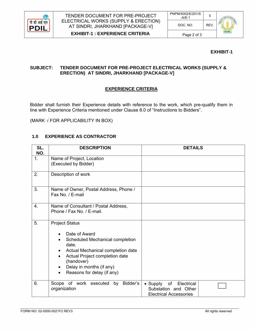
TENDER DOCUMENT FOR PRE-PROJECT
ELECTRICAL WORKS (SUPPLY & ERECTION) AT SINDRI, JHARKHAND [PACKAGE-V]
EXHIBIT-1 : EXPERIENCE CRITERIA
PNPM/5002/E/201/S-A/E-1 0
DOC. NO. REV.
Page 2 of 3
FORM NO: 02-0000-0021F2 REV3 All rights reserved
EXHIBIT-1
SUBJECT: TENDER DOCUMENT FOR PRE-PROJECT ELECTRICAL WORKS (SUPPLY & ERECTION) AT SINDRI, JHARKHAND [PACKAGE-V]
EXPERIENCE CRITERIA
Bidder shall furnish their Experience details with reference to the work, which pre-qualify them in line with Experience Criteria mentioned under Clause 8.0 of “Instructions to Bidders”. (MARK √ FOR APPLICABILITY IN BOX)
1.0 EXPERIENCE AS CONTRACTOR
SL. NO.
DESCRIPTION DETAILS
1. Name of Project, Location (Executed by Bidder)
2. Description of work
3. Name of Owner, Postal Address, Phone / Fax No. / E-mail
4. Name of Consultant / Postal Address, Phone / Fax No. / E-mail.
5. Project Status
• Date of Award • Scheduled Mechanical completion
date. • Actual Mechanical completion date • Actual Project completion date
(handover) • Delay in months (if any) • Reasons for delay (if any)
6.
Scope of work executed by Bidder’s organization
• Supply of Electrical Substation and Other Electrical Accessories
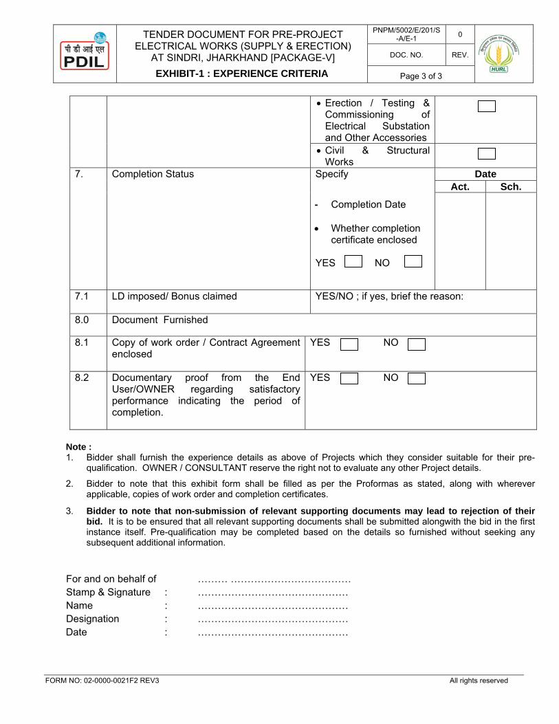
TENDER DOCUMENT FOR PRE-PROJECT
ELECTRICAL WORKS (SUPPLY & ERECTION) AT SINDRI, JHARKHAND [PACKAGE-V]
EXHIBIT-1 : EXPERIENCE CRITERIA
PNPM/5002/E/201/S-A/E-1 0
DOC. NO. REV.
Page 3 of 3
FORM NO: 02-0000-0021F2 REV3 All rights reserved
• Erection / Testing & Commissioning of Electrical Substation and Other Accessories
• Civil & Structural Works
7. Completion Status Specify
- Completion Date • Whether completion
certificate enclosed YES NO
Date Act. Sch.
7.1 LD imposed/ Bonus claimed YES/NO ; if yes, brief the reason:
8.0 Document Furnished
8.1 Copy of work order / Contract Agreement enclosed
YES NO
8.2 Documentary proof from the End User/OWNER regarding satisfactory performance indicating the period of completion.
YES NO
Note : 1. Bidder shall furnish the experience details as above of Projects which they consider suitable for their pre-
qualification. OWNER / CONSULTANT reserve the right not to evaluate any other Project details.
2. Bidder to note that this exhibit form shall be filled as per the Proformas as stated, along with wherever applicable, copies of work order and completion certificates.
3. Bidder to note that non-submission of relevant supporting documents may lead to rejection of their bid. It is to be ensured that all relevant supporting documents shall be submitted alongwith the bid in the first instance itself. Pre-qualification may be completed based on the details so furnished without seeking any subsequent additional information.
For and on behalf of ……… ……………………………… Stamp & Signature : ……………………………………… Name : ……………………………………… Designation : ……………………………………… Date : ………………………………………
PROJECTS & DEVELOPMENT INDIA LIMITED
PNPM/5002/E/201/S-A/E-2 0
DOC. NO. REV.
Page 1 of 4
SECTION-A : COMMERCIAL
EXHIBIT-2
FINANCIAL CRITERIA
0 06.11.2017 FOR TENDER AKR PKM RRK P 08.09.2017 FOR TENDER AKR PKM RRK
REV. DATE PURPOSE PREPARED REVIEWED APPROVED
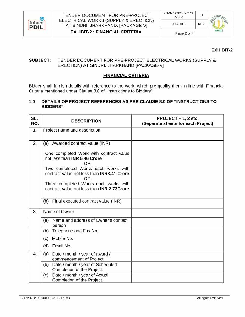
TENDER DOCUMENT FOR PRE-PROJECT
ELECTRICAL WORKS (SUPPLY & ERECTION) AT SINDRI, JHARKHAND. [PACKAGE-V]
EXHIBIT-2 : FINANCIAL CRITERIA
PNPM/5002/E/201/S-A/E-2 0
DOC. NO. REV.
Page 2 of 4
FORM NO: 02-0000-0021F2 REV3 All rights reserved
EXHIBIT-2
SUBJECT: TENDER DOCUMENT FOR PRE-PROJECT ELECTRICAL WORKS (SUPPLY &
ERECTION) AT SINDRI, JHARKHAND [PACKAGE-V]
FINANCIAL CRITERIA
Bidder shall furnish details with reference to the work, which pre-qualify them in line with Financial Criteria mentioned under Clause 8.0 of “Instructions to Bidders”.
1.0 DETAILS OF PROJECT REFERENCES AS PER CLAUSE 8.0 OF “INSTRUCTIONS TO BIDDERS”
SL. NO. DESCRIPTION PROJECT – 1, 2 etc.
(Separate sheets for each Project) 1. Project name and description
2. (a) Awarded contract value (INR) One completed Work with contract value not less than INR 5.46 Crore
OR Two completed Works each works with contract value not less than INR3.41 Crore
OR Three completed Works each works with contract value not less than INR 2.73Crore
(b) Final executed contract value (INR)
3. Name of Owner
(a) Name and address of Owner’s contact person
(b) Telephone and Fax No.
(c) Mobile No.
(d) Email No.
4. (a) Date / month / year of award / commencement of Project
(b) Date / month / year of Scheduled Completion of the Project.
(c) Date / month / year of Actual Completion of the Project.
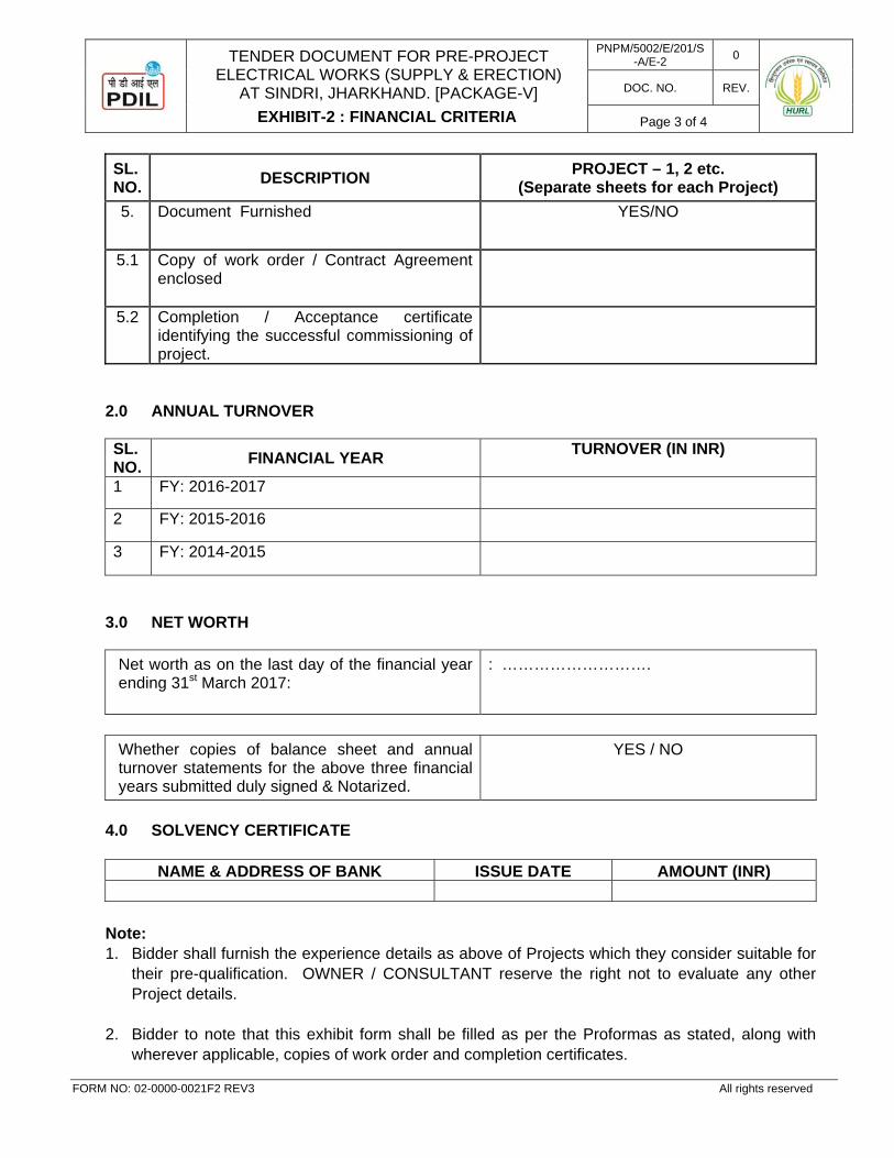
TENDER DOCUMENT FOR PRE-PROJECT
ELECTRICAL WORKS (SUPPLY & ERECTION) AT SINDRI, JHARKHAND. [PACKAGE-V]
EXHIBIT-2 : FINANCIAL CRITERIA
PNPM/5002/E/201/S-A/E-2 0
DOC. NO. REV.
Page 3 of 4
FORM NO: 02-0000-0021F2 REV3 All rights reserved
SL. NO. DESCRIPTION PROJECT – 1, 2 etc.
(Separate sheets for each Project) 5. Document Furnished YES/NO
5.1 Copy of work order / Contract Agreement enclosed
5.2 Completion / Acceptance certificate identifying the successful commissioning of project.
2.0 ANNUAL TURNOVER SL. NO. FINANCIAL YEAR TURNOVER (IN INR)
1 FY: 2016-2017
2 FY: 2015-2016
3 FY: 2014-2015
3.0 NET WORTH
Net worth as on the last day of the financial year ending 31st March 2017:
: ……………………….
Whether copies of balance sheet and annual turnover statements for the above three financial years submitted duly signed & Notarized.
YES / NO
4.0 SOLVENCY CERTIFICATE
NAME & ADDRESS OF BANK ISSUE DATE AMOUNT (INR)
Note: 1. Bidder shall furnish the experience details as above of Projects which they consider suitable for
their pre-qualification. OWNER / CONSULTANT reserve the right not to evaluate any other Project details.
2. Bidder to note that this exhibit form shall be filled as per the Proformas as stated, along with
wherever applicable, copies of work order and completion certificates.

TENDER DOCUMENT FOR PRE-PROJECT
ELECTRICAL WORKS (SUPPLY & ERECTION) AT SINDRI, JHARKHAND. [PACKAGE-V]
EXHIBIT-2 : FINANCIAL CRITERIA
PNPM/5002/E/201/S-A/E-2 0
DOC. NO. REV.
Page 4 of 4
FORM NO: 02-0000-0021F2 REV3 All rights reserved
3. The bidder shall attach fresh solvency certificate issued by his banker. The solvency certificate
shall not be more than six months old from the date of issue of NIT OR minimum credit ratings of “A” from ICRA/CRISIL etc OR equivalent reputed institutions, OR financing/credit limits from bank of value not less than INR 2.75 Crores valid as on date of issue of ITB.
4. Bidder to note that non-submission of relevant supporting documents may lead to
rejection of their bid. It is to be ensured that all relevant supporting documents shall be submitted alongwith the bid in the first instance itself. Pre-qualification may be completed based on the details so furnished without seeking any subsequent additional information.
For and on behalf of : ……….……………………………… Stamp & Signature : ……………………………………… Name : .……………………………………… Designation : ……………………………………… Mobile No : ……………………………………… Email ID : ……………………………………… Date : ………………………………………
TENDER DOCUMENT FOR PRE-PROJECT ELECTRICAL WORKS (SUPPLY & ERECTION)
AT SINDRI, JHARKHAND [PACKAGE-V]
TENDER ACCEPTANCE LETTER
PNPM/5002/E/201/S-A/A-1.1 0
DOC. NO. REV.
Page 1 of 2
FORM NO: 02-0000-0021F2 REV3 All rights reserved
SECTION-A : COMMERCIAL
ANNEXURE-1.1
TENDER ACCEPTANCE LETTER
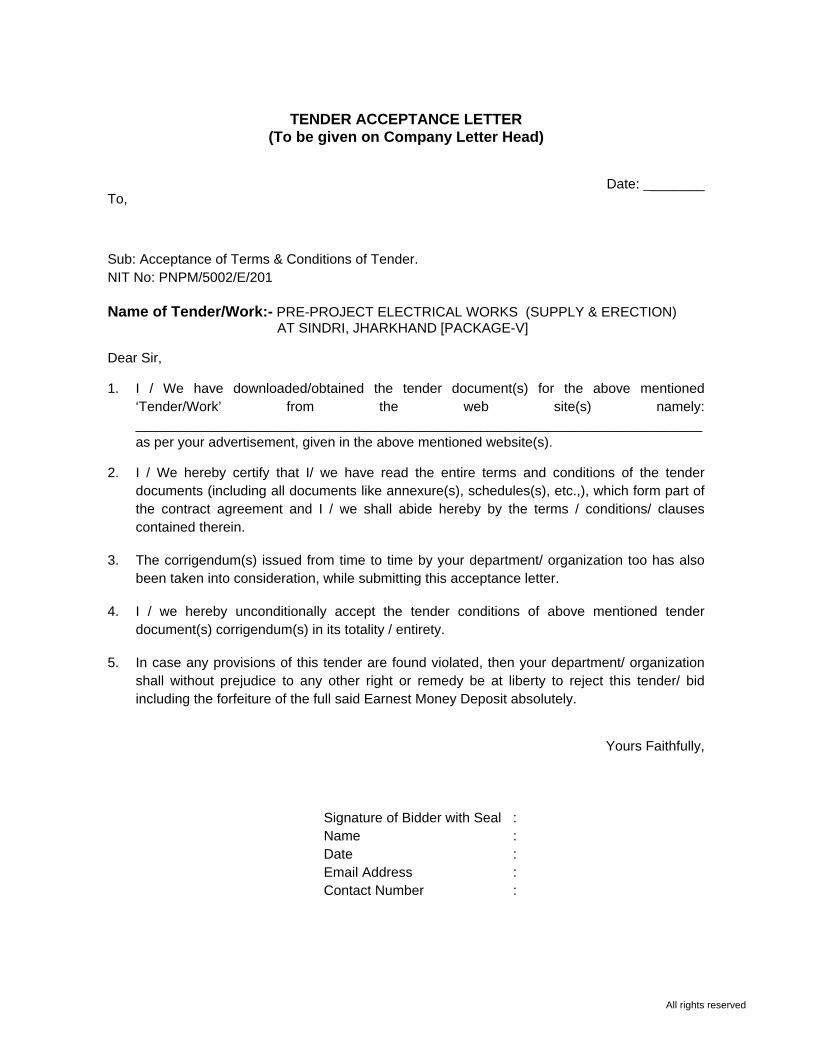
All rights reserved
TENDER ACCEPTANCE LETTER
(To be given on Company Letter Head)
Date: ________
To, Sub: Acceptance of Terms & Conditions of Tender. NIT No: PNPM/5002/E/201 Name of Tender/Work:- PRE-PROJECT ELECTRICAL WORKS (SUPPLY & ERECTION) AT SINDRI, JHARKHAND [PACKAGE-V] Dear Sir, 1. I / We have downloaded/obtained the tender document(s) for the above mentioned
‘Tender/Work’ from the web site(s) namely: __________________________________________________________________________ as per your advertisement, given in the above mentioned website(s).
2. I / We hereby certify that I/ we have read the entire terms and conditions of the tender
documents (including all documents like annexure(s), schedules(s), etc.,), which form part of the contract agreement and I / we shall abide hereby by the terms / conditions/ clauses contained therein.
3. The corrigendum(s) issued from time to time by your department/ organization too has also
been taken into consideration, while submitting this acceptance letter. 4. I / we hereby unconditionally accept the tender conditions of above mentioned tender
document(s) corrigendum(s) in its totality / entirety. 5. In case any provisions of this tender are found violated, then your department/ organization
shall without prejudice to any other right or remedy be at liberty to reject this tender/ bid including the forfeiture of the full said Earnest Money Deposit absolutely.
Yours Faithfully,
Signature of Bidder with Seal : Name : Date : Email Address : Contact Number :
TENDER DOCUMENT FOR PRE-PROJECT ELECTRICAL WORKS (SUPPLY & ERECTION)
AT SINDRI, JHARKHAND [PACKAGE-V]
COMMERCIAL QUESTIONNAIRE
PNPM/5002/E/201/S-A/A-1.2 0
DOC. NO. REV.
Page 1 of 5
FORM NO: 02-0000-0021F2 REV3 All rights reserved
SECTION-A : COMMERCIAL
ANNEXURE-1.2
COMMERCIAL QUESTIONNAIRE
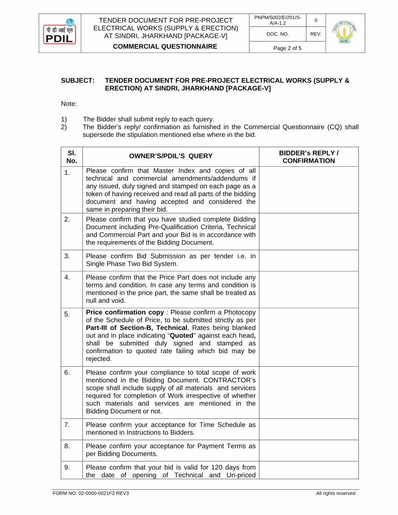
TENDER DOCUMENT FOR PRE-PROJECT ELECTRICAL WORKS (SUPPLY & ERECTION)
AT SINDRI, JHARKHAND [PACKAGE-V]
COMMERCIAL QUESTIONNAIRE
PNPM/5002/E/201/S-A/A-1.2 0
DOC. NO. REV.
Page 2 of 5
FORM NO: 02-0000-0021F2 REV3 All rights reserved
SUBJECT: TENDER DOCUMENT FOR PRE-PROJECT ELECTRICAL WORKS (SUPPLY &
ERECTION) AT SINDRI, JHARKHAND [PACKAGE-V] Note:
1) The Bidder shall submit reply to each query. 2) The Bidder’s reply/ confirmation as furnished in the Commercial Questionnaire (CQ) shall
supersede the stipulation mentioned else where in the bid.
Sl. No.
OWNER’S/PDIL’S QUERY BIDDER’s REPLY / CONFIRMATION
1. Please confirm that Master Index and copies of all technical and commercial amendments/addendums if any issued, duly signed and stamped on each page as a token of having received and read all parts of the bidding document and having accepted and considered the same in preparing their bid.
2. Please confirm that you have studied complete Bidding Document including Pre-Qualification Criteria, Technical and Commercial Part and your Bid is in accordance with the requirements of the Bidding Document.
3. Please confirm Bid Submission as per tender i.e. in Single Phase Two Bid System.
4. Please confirm that the Price Part does not include any terms and condition. In case any terms and condition is mentioned in the price part, the same shall be treated as null and void.
5. Price confirmation copy : Please confirm a Photocopy of the Schedule of Price, to be submitted strictly as per Part-III of Section-B, Technical, Rates being blanked out and in place indicating “Quoted” against each head, shall be submitted duly signed and stamped as confirmation to quoted rate failing which bid may be rejected.
6. Please confirm your compliance to total scope of work mentioned in the Bidding Document. CONTRACTOR’s scope shall include supply of all materials and services required for completion of Work irrespective of whether such materials and services are mentioned in the Bidding Document or not.
7. Please confirm your acceptance for Time Schedule as mentioned in Instructions to Bidders.
8. Please confirm your acceptance for Payment Terms as per Bidding Documents.
9. Please confirm that your bid is valid for 120 days from the date of opening of Technical and Un-priced
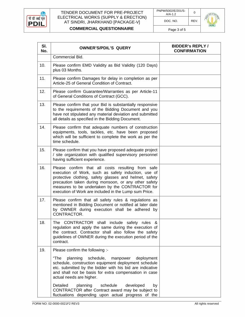
TENDER DOCUMENT FOR PRE-PROJECT ELECTRICAL WORKS (SUPPLY & ERECTION)
AT SINDRI, JHARKHAND [PACKAGE-V]
COMMERCIAL QUESTIONNAIRE
PNPM/5002/E/201/S-A/A-1.2 0
DOC. NO. REV.
Page 3 of 5
FORM NO: 02-0000-0021F2 REV3 All rights reserved
Sl. No.
OWNER’S/PDIL’S QUERY BIDDER’s REPLY / CONFIRMATION
Commercial Bid.
10. Please confirm EMD Validity as Bid Validity (120 Days) plus 03 Months.
11. Please confirm Damages for delay in completion as per Article-25 of General Condition of Contract.
12. Please confirm Guarantee/Warranties as per Article-11 of General Conditions of Contract (GCC).
13. Please confirm that your Bid is substantially responsive to the requirements of the Bidding Document and you have not stipulated any material deviation and submitted all details as specified in the Bidding Document.
14. Please confirm that adequate numbers of construction equipments, tools, tackles, etc. have been proposed which will be sufficient to complete the work as per the time schedule.
15. Please confirm that you have proposed adequate project / site organization with qualified supervisory personnel having sufficient experience.
16. Please confirm that all costs resulting from safe execution of Work, such as safety induction, use of protective clothing, safety glasses and helmet, safety precaution taken during monsoon, or any other safety measures to be undertaken by the CONTRACTOR for execution of Work are included in the Lump sum Price.
17. Please confirm that all safety rules & regulations as mentioned in Bidding Document or notified at later date by OWNER during execution shall be adhered by CONTRACTOR.
18. The CONTRACTOR shall include safety rules & regulation and apply the same during the execution of the contract. Contractor shall also follow the safety guidelines of OWNER during the execution period of the contract.
19. Please confirm the following :-
“The planning schedule, manpower deployment schedule, construction equipment deployment schedule etc. submitted by the bidder with his bid are indicative and shall not be basis for extra compensation in case actual needs are higher.
Detailed planning schedule developed by CONTRACTOR after Contract award may be subject to fluctuations depending upon actual progress of the
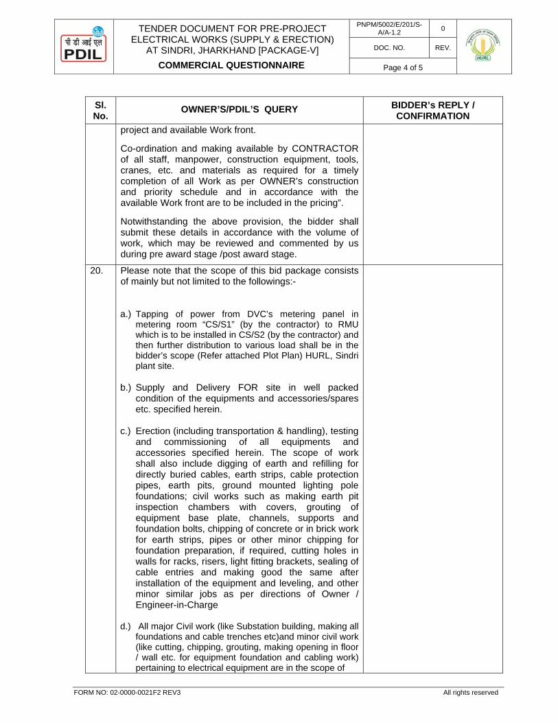
TENDER DOCUMENT FOR PRE-PROJECT ELECTRICAL WORKS (SUPPLY & ERECTION)
AT SINDRI, JHARKHAND [PACKAGE-V]
COMMERCIAL QUESTIONNAIRE
PNPM/5002/E/201/S-A/A-1.2 0
DOC. NO. REV.
Page 4 of 5
FORM NO: 02-0000-0021F2 REV3 All rights reserved
Sl. No.
OWNER’S/PDIL’S QUERY BIDDER’s REPLY / CONFIRMATION
project and available Work front.
Co-ordination and making available by CONTRACTOR of all staff, manpower, construction equipment, tools, cranes, etc. and materials as required for a timely completion of all Work as per OWNER’s construction and priority schedule and in accordance with the available Work front are to be included in the pricing”.
Notwithstanding the above provision, the bidder shall submit these details in accordance with the volume of work, which may be reviewed and commented by us during pre award stage /post award stage.
20. Please note that the scope of this bid package consists of mainly but not limited to the followings:- a.) Tapping of power from DVC’s metering panel in
metering room “CS/S1” (by the contractor) to RMU which is to be installed in CS/S2 (by the contractor) and then further distribution to various load shall be in the bidder’s scope (Refer attached Plot Plan) HURL, Sindri plant site.
b.) Supply and Delivery FOR site in well packed condition of the equipments and accessories/spares etc. specified herein.
c.) Erection (including transportation & handling), testing and commissioning of all equipments and accessories specified herein. The scope of work shall also include digging of earth and refilling for directly buried cables, earth strips, cable protection pipes, earth pits, ground mounted lighting pole foundations; civil works such as making earth pit inspection chambers with covers, grouting of equipment base plate, channels, supports and foundation bolts, chipping of concrete or in brick work for earth strips, pipes or other minor chipping for foundation preparation, if required, cutting holes in walls for racks, risers, light fitting brackets, sealing of cable entries and making good the same after installation of the equipment and leveling, and other minor similar jobs as per directions of Owner / Engineer-in-Charge
d.) All major Civil work (like Substation building, making all foundations and cable trenches etc)and minor civil work (like cutting, chipping, grouting, making opening in floor / wall etc. for equipment foundation and cabling work) pertaining to electrical equipment are in the scope of
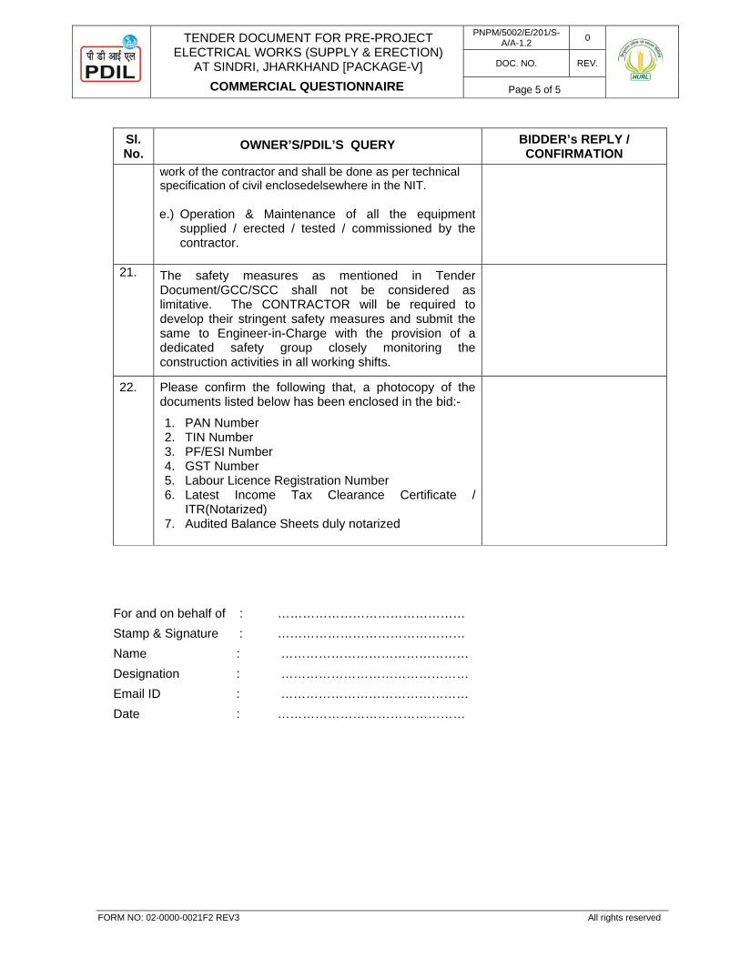
TENDER DOCUMENT FOR PRE-PROJECT ELECTRICAL WORKS (SUPPLY & ERECTION)
AT SINDRI, JHARKHAND [PACKAGE-V]
COMMERCIAL QUESTIONNAIRE
PNPM/5002/E/201/S-A/A-1.2 0
DOC. NO. REV.
Page 5 of 5
FORM NO: 02-0000-0021F2 REV3 All rights reserved
Sl. No.
OWNER’S/PDIL’S QUERY BIDDER’s REPLY / CONFIRMATION
work of the contractor and shall be done as per technical specification of civil enclosedelsewhere in the NIT.
e.) Operation & Maintenance of all the equipment
supplied / erected / tested / commissioned by the contractor.
21. The safety measures as mentioned in Tender Document/GCC/SCC shall not be considered as limitative. The CONTRACTOR will be required to develop their stringent safety measures and submit the same to Engineer-in-Charge with the provision of a dedicated safety group closely monitoring the construction activities in all working shifts.
22. Please confirm the following that, a photocopy of the documents listed below has been enclosed in the bid:-
1. PAN Number 2. TIN Number 3. PF/ESI Number 4. GST Number 5. Labour Licence Registration Number 6. Latest Income Tax Clearance Certificate /
ITR(Notarized) 7. Audited Balance Sheets duly notarized
For and on behalf of : ……………………………………… Stamp & Signature : ……………………………………… Name : ……………………………………… Designation : ……………………………………… Email ID : ……………………………………… Date : ………………………………………
TENDER DOCUMENT FOR PRE-PROJECT ELECTRICAL WORKS (SUPPLY & ERECTION)
AT SINDRI, JHARKHAND [PACKAGE-V]
NO DEVIATION CERTIFICATE
PNPM/5002/E/201/S-A/A-1.3 0
DOC. NO. REV.
Page 1 of 2
FORM NO: 02-0000-0021F2 REV3 All rights reserved
SECTION-A : COMMERCIAL
ANNEXURE-1.3
NO DEVIATION CERTIFICATE
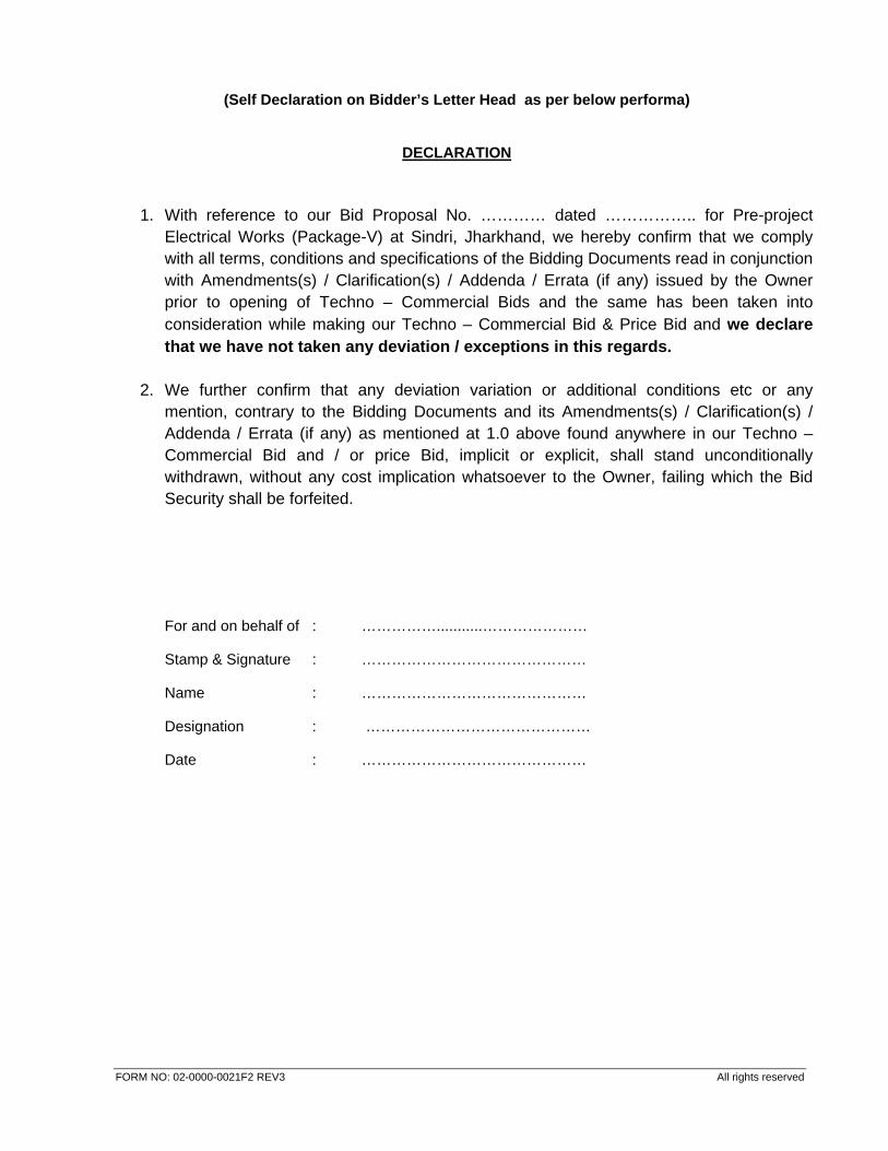
FORM NO: 02-0000-0021F2 REV3 All rights reserved
(Self Declaration on Bidder’s Letter Head as per below performa)
DECLARATION
1. With reference to our Bid Proposal No. ………… dated …………….. for Pre-project
Electrical Works (Package-V) at Sindri, Jharkhand, we hereby confirm that we comply with all terms, conditions and specifications of the Bidding Documents read in conjunction with Amendments(s) / Clarification(s) / Addenda / Errata (if any) issued by the Owner prior to opening of Techno – Commercial Bids and the same has been taken into consideration while making our Techno – Commercial Bid & Price Bid and we declare that we have not taken any deviation / exceptions in this regards.
2. We further confirm that any deviation variation or additional conditions etc or any mention, contrary to the Bidding Documents and its Amendments(s) / Clarification(s) / Addenda / Errata (if any) as mentioned at 1.0 above found anywhere in our Techno – Commercial Bid and / or price Bid, implicit or explicit, shall stand unconditionally withdrawn, without any cost implication whatsoever to the Owner, failing which the Bid Security shall be forfeited.
For and on behalf of : ……………...........…………………
Stamp & Signature : ………………………………………
Name : ………………………………………
Designation : ………………………………………
Date : ………………………………………
TENDER DOCUMENT FOR PRE-PROJECT ELECTRICAL WORKS (SUPPLY & ERECTION) AT SINDRI, JHARKHAND [PACKAGE-V]
DETAILS OF SIMILAR WORKS EXECUTED
PNPM/5002/E/201/S-A/A-1.4 0
DOC. NO. REV.
Page 1 of 2
FORM NO: 02-0000-0021 F2 REV3 All rights reserved
SECTION-A : COMMERCIAL
ANNEXURE-1.4
DETAILS OF SIMILAR WORKS EXECUTED

TENDER DOCUMENT FOR PRE-PROJECT ELECTRICAL WORKS (SUPPLY & ERECTION) AT SINDRI, JHARKHAND [PACKAGE-V]
DETAILS OF SIMILAR WORKS EXECUTED
PNPM/5002/E/201/S-A/A-1.4 0
DOC. NO. REV.
Page 2 of 2
FORM NO: 02-0000-0021 F2 REV3 All rights reserved
SUBJECT: TENDER DOCUMENT FOR PRE-PROJECT ELECTRICAL WORKS (SUPPLY & ERECTION) AT SINDRI, JHARKHAND [PACKAGE-V]
NAME OF THE PROJECT: BIDDER TO FILL SL. NO.
FULL POSTAL ADDRESS OF CLIENT
AND NAME OF OFFICER IN-CHARGE WITH PHONE/CELL
NO AND E-MAIL
DESCRIPTION OF THE WORK
VALUE OF CONTRACT
DATE OF COMMENCEMENT
OF WORK
SCHEDULED COMPLETION
PERIOD
ACTUAL COMPLETION
DATE
REMARKS
Note : 1) Description of work should be in detail.
2) Please also indicate the major problems if any, faced during construction of works.
STAMP & SIGNATURE OF BIDDER : __________________________________
NAME OF BIDDER : __________________________________
DATE : __________________________________

TENDER DOCUMENT FOR PRE-PROJECT ELECTRICAL WORKS
(SUPPLY & ERECTION) AT SINDRI, JHARKHAND [PACKAGE-V]
CURRENT COMMITMENTS
PNPM/5002/E/201/S-A/A-1.5 0
DOC. NO. REV.
Page 1 of 2
FORM NO: 02-0000-0021 F2 REV3 All rights reserved
SECTION-A : COMMERCIAL
ANNEXURE-1.5
CURRENT COMMITMENTS
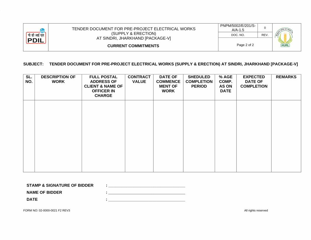
TENDER DOCUMENT FOR PRE-PROJECT ELECTRICAL WORKS
(SUPPLY & ERECTION) AT SINDRI, JHARKHAND [PACKAGE-V]
CURRENT COMMITMENTS
PNPM/5002/E/201/S-A/A-1.5 0
DOC. NO. REV.
Page 2 of 2
FORM NO: 02-0000-0021 F2 REV3 All rights reserved
SUBJECT: TENDER DOCUMENT FOR PRE-PROJECT ELECTRICAL WORKS (SUPPLY & ERECTION) AT SINDRI, JHARKHAND [PACKAGE-V]
SL. NO.
DESCRIPTION OF WORK
FULL POSTAL ADDRESS OF
CLIENT & NAME OF OFFICER IN
CHARGE
CONTRACT VALUE
DATE OF COMMENCE
MENT OF WORK
SHEDULED COMPLETION
PERIOD
% AGE COMP. AS ON DATE
EXPECTED DATE OF
COMPLETION
REMARKS
STAMP & SIGNATURE OF BIDDER : __________________________________ NAME OF BIDDER : __________________________________ DATE : __________________________________
TENDER DOCUMENT FOR PRE-PROJECT ELECTRICAL WORKS
(SUPPLY & ERECTION) AT SINDRI, JHARKHAND [PACKAGE-V]
DEPLOYMENT SCHEDULE FOR SUPERVISORY PERSONNEL
PNPM/5002/E/201/S-A/A-1.6 0
DOC. NO. REV.
Page 1 of 2
FORM NO: 02-0000-0021 F2 REV3 All rights reserved
SECTION-A : COMMERCIAL
ANNEXURE-1.6
DEPLOYMENT SCHEDULE FOR SUPERVISORY PERSONNEL
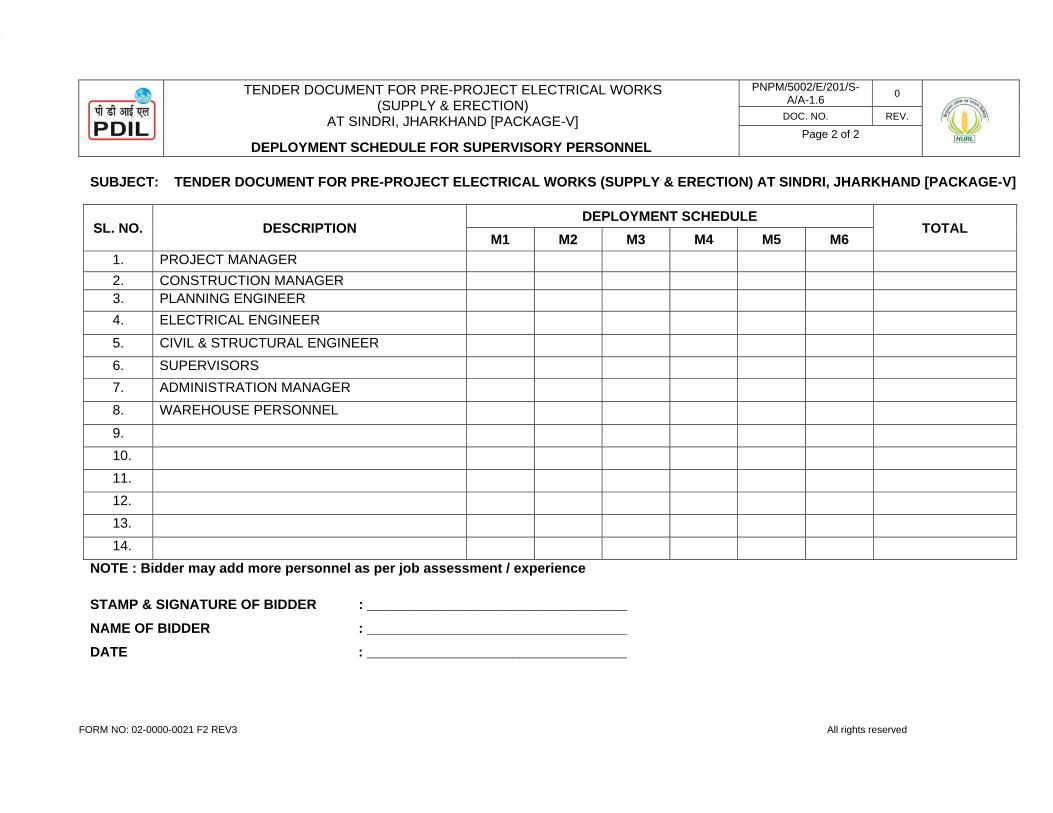
TENDER DOCUMENT FOR PRE-PROJECT ELECTRICAL WORKS
(SUPPLY & ERECTION) AT SINDRI, JHARKHAND [PACKAGE-V]
DEPLOYMENT SCHEDULE FOR SUPERVISORY PERSONNEL
PNPM/5002/E/201/S-A/A-1.6 0
DOC. NO. REV.
Page 2 of 2
FORM NO: 02-0000-0021 F2 REV3 All rights reserved
SUBJECT: TENDER DOCUMENT FOR PRE-PROJECT ELECTRICAL WORKS (SUPPLY & ERECTION) AT SINDRI, JHARKHAND [PACKAGE-V]
SL. NO. DESCRIPTION DEPLOYMENT SCHEDULE
TOTAL M1 M2 M3 M4 M5 M6
1. PROJECT MANAGER 2. CONSTRUCTION MANAGER 3. PLANNING ENGINEER 4. ELECTRICAL ENGINEER
5. CIVIL & STRUCTURAL ENGINEER 6. SUPERVISORS 7. ADMINISTRATION MANAGER 8. WAREHOUSE PERSONNEL
9. 10. 11. 12. 13. 14.
NOTE : Bidder may add more personnel as per job assessment / experience
STAMP & SIGNATURE OF BIDDER : __________________________________ NAME OF BIDDER : __________________________________ DATE : __________________________________

TENDER DOCUMENT FOR PRE-PROJECT ELECTRICAL WORKS
(SUPPLY & ERECTION) AT SINDRI, JHARKHAND [PACKAGE-V]
DEPLOYMENT SCHEDULE FOR CONSTRUCTION EQUIPMENT
PNPM/5002/E/201/S-A/A-1.7 0
DOC. NO. REV.
Page 1 of 2
FORM NO: 02-0000-0021 F2 REV3 All rights reserved
SECTION-A : COMMERCIAL
ANNEXURE-1.7
DEPLOYMENT SCHEDULE FOR CONSTRUCTION EQUIPMENT

TENDER DOCUMENT FOR PRE-PROJECT ELECTRICAL WORKS
(SUPPLY & ERECTION) AT SINDRI, JHARKHAND [PACKAGE-V]
DEPLOYMENT SCHEDULE FOR CONSTRUCTION EQUIPMENT
PNPM/5002/E/201/S-A/A-1.7 0
DOC. NO. REV.
Page 2 of 2
FORM NO: 02-0000-0021 F2 REV3 All rights reserved
SUBJECT: TENDER DOCUMENT FOR PRE-PROJECT ELECTRICAL WORKS (SUPPLY & ERECTION) AT SINDRI, JHARKHAND [PACKAGE-V]
SL. NO. DESCRIPTION CAPACITY DEPLOYMENT SCHEDULE TOTAL M1 M2 M3 M4 M5 M6
1. CRANES 2. DIESEL GENERATORS 3. WELDING MACHINE 4. TRACTORS
5. TRAILERS / TRUCKS 6. DUMPERS 7. EXCAVATORS 8. VIBRATOR
9. COMPACTORS 10. OTHER TOOLS & TACKLES 11. 12. 13. 14.
NOTE : Bidder may add more Equipments as per job assessment / experience.
STAMP & SIGNATURE OF BIDDER : __________________________________ NAME OF BIDDER : __________________________________ DATE : __________________________________
TENDER DOCUMENT FOR PRE-PROJECT ELECTRICAL WORKS (SUPPLY & ERECTION)
AT SINDRI, JHARKHAND [PACKAGE-V]
DETAILS OF EQUIPMENT PROPOSED FOR TENDERED WORK
PNPM/5002/E/201/S-A/A-1.8 0
DOC. NO. REV.
Page 1 of 2
FORM NO: 02-0000-0021 F2 REV3 All rights reserved
SECTION-A : COMMERCIAL
ANNEXURE-1.8
DETAILS OF EQUIPMENT PROPOSED FOR TENDERED WORK
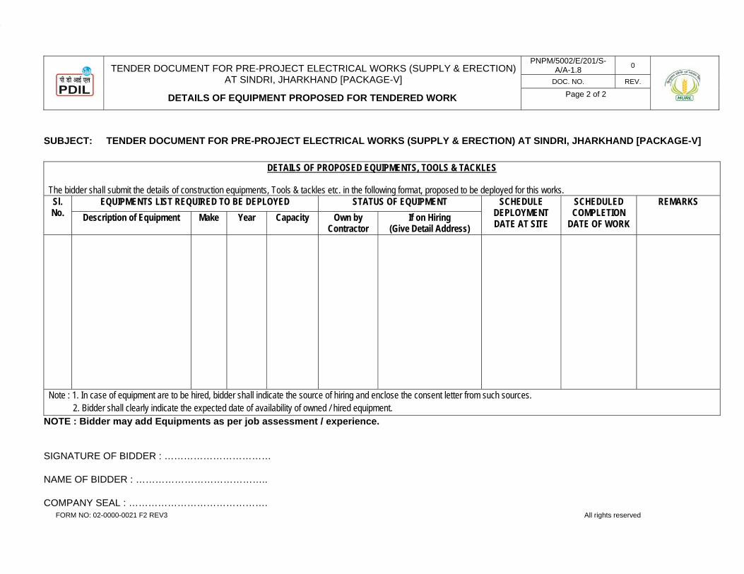
TENDER DOCUMENT FOR PRE-PROJECT ELECTRICAL WORKS (SUPPLY & ERECTION)
AT SINDRI, JHARKHAND [PACKAGE-V]
DETAILS OF EQUIPMENT PROPOSED FOR TENDERED WORK
PNPM/5002/E/201/S-A/A-1.8 0
DOC. NO. REV.
Page 2 of 2
FORM NO: 02-0000-0021 F2 REV3 All rights reserved
SUBJECT: TENDER DOCUMENT FOR PRE-PROJECT ELECTRICAL WORKS (SUPPLY & ERECTION) AT SINDRI, JHARKHAND [PACKAGE-V]
DETAILS OF PROPOSED EQUIPMENTS, TOOLS & TACKLES
The bidder shall submit the details of construction equipments, Tools & tackles etc. in the following format, proposed to be deployed for this works. Sl. No.
EQUIPMENTS LIST REQUIRED TO BE DEPLOYED STATUS OF EQUIPMENT SCHEDULE DEPLOYMENT DATE AT SITE
SCHEDULED COMPLETION
DATE OF WORK
REMARKS Description of Equipment Make Year Capacity Own by
Contractor If on Hiring
(Give Detail Address)
Note : 1. In case of equipment are to be hired, bidder shall indicate the source of hiring and enclose the consent letter from such sources. 2. Bidder shall clearly indicate the expected date of availability of owned / hired equipment.
NOTE : Bidder may add Equipments as per job assessment / experience.
SIGNATURE OF BIDDER : ……………………………
NAME OF BIDDER : …………………………………..
COMPANY SEAL : …………………………………….

TENDER DOCUMENT FOR PRE-PROJECT ELECTRICAL WORKS (SUPPLY & ERECTION)
AT SINDRI, JHARKHAND [PACKAGE-V]
CONTENTS OF BID & CHECK LIST
PNPM/5002/E/201/S-A/A-1.9 0
DOC. NO. REV.
Page 1 of 3
FORM NO: 02-0000-0021F2 REV3 All rights reserved
SECTION-A : COMMERCIAL
ANNEXURE-1.9
CONTENTS OF BID AND CHECK LIST
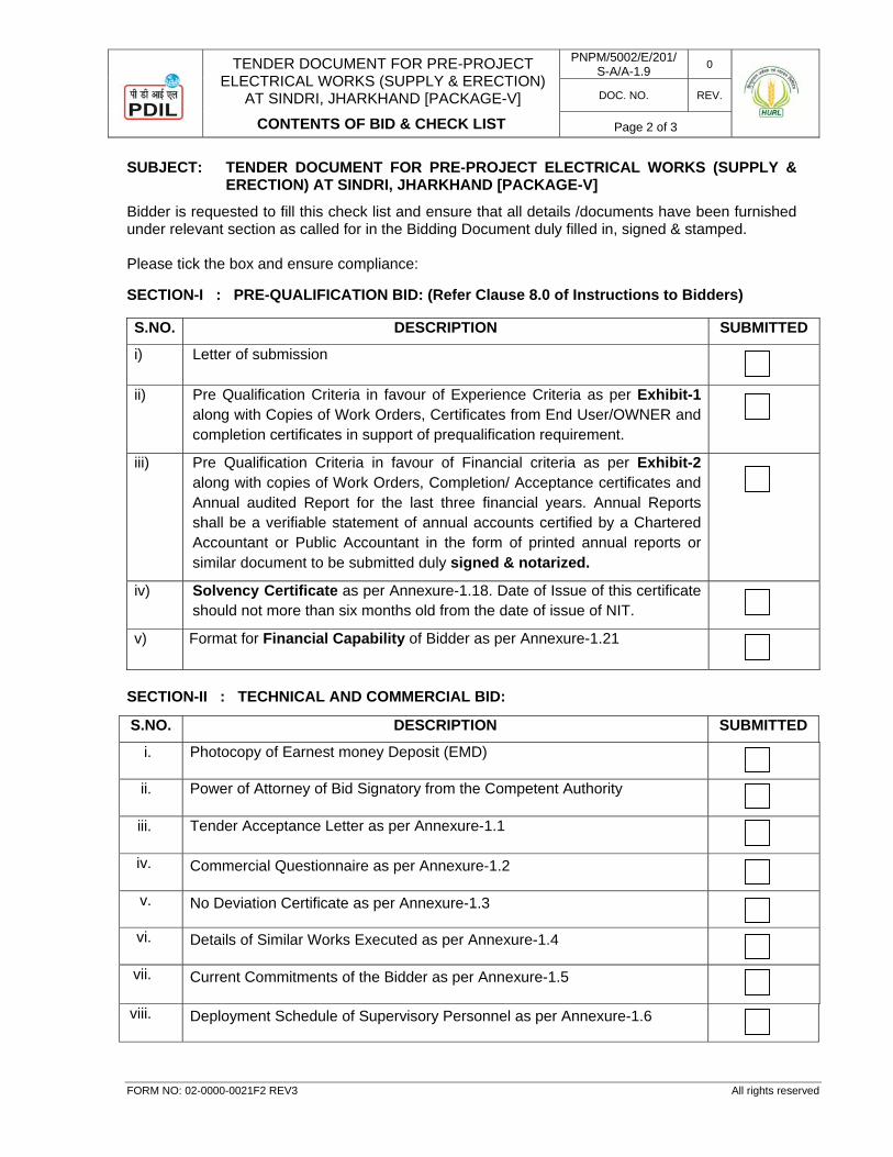
TENDER DOCUMENT FOR PRE-PROJECT ELECTRICAL WORKS (SUPPLY & ERECTION)
AT SINDRI, JHARKHAND [PACKAGE-V]
CONTENTS OF BID & CHECK LIST
PNPM/5002/E/201/S-A/A-1.9 0
DOC. NO. REV.
Page 2 of 3
FORM NO: 02-0000-0021F2 REV3 All rights reserved
SUBJECT: TENDER DOCUMENT FOR PRE-PROJECT ELECTRICAL WORKS (SUPPLY & ERECTION) AT SINDRI, JHARKHAND [PACKAGE-V]
Bidder is requested to fill this check list and ensure that all details /documents have been furnished under relevant section as called for in the Bidding Document duly filled in, signed & stamped. Please tick the box and ensure compliance:
SECTION-I : PRE-QUALIFICATION BID: (Refer Clause 8.0 of Instructions to Bidders)
S.NO. DESCRIPTION SUBMITTED
i) Letter of submission
ii) Pre Qualification Criteria in favour of Experience Criteria as per Exhibit-1 along with Copies of Work Orders, Certificates from End User/OWNER and completion certificates in support of prequalification requirement.
iii) Pre Qualification Criteria in favour of Financial criteria as per Exhibit-2 along with copies of Work Orders, Completion/ Acceptance certificates and Annual audited Report for the last three financial years. Annual Reports shall be a verifiable statement of annual accounts certified by a Chartered Accountant or Public Accountant in the form of printed annual reports or similar document to be submitted duly signed & notarized.
iv) Solvency Certificate as per Annexure-1.18. Date of Issue of this certificate should not more than six months old from the date of issue of NIT.
v) Format for Financial Capability of Bidder as per Annexure-1.21
SECTION-II : TECHNICAL AND COMMERCIAL BID:
S.NO. DESCRIPTION SUBMITTED
i. Photocopy of Earnest money Deposit (EMD)
ii. Power of Attorney of Bid Signatory from the Competent Authority
iii. Tender Acceptance Letter as per Annexure-1.1
iv. Commercial Questionnaire as per Annexure-1.2
v. No Deviation Certificate as per Annexure-1.3
vi. Details of Similar Works Executed as per Annexure-1.4
vii. Current Commitments of the Bidder as per Annexure-1.5
viii. Deployment Schedule of Supervisory Personnel as per Annexure-1.6
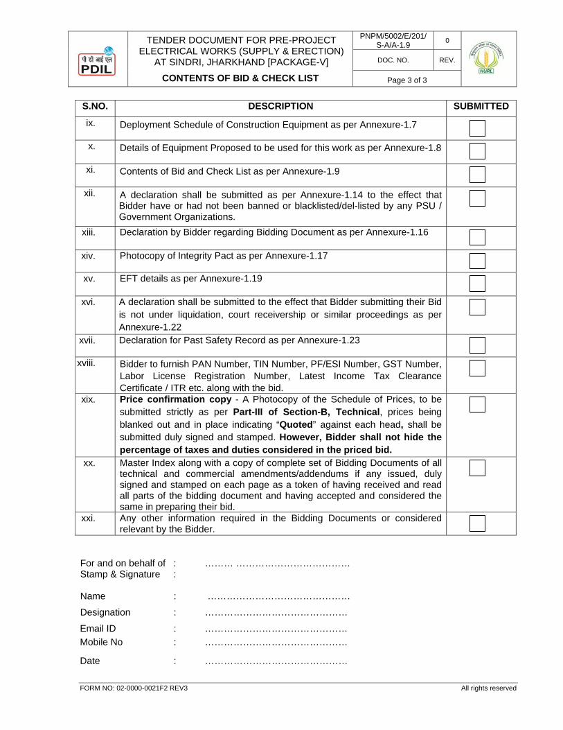
TENDER DOCUMENT FOR PRE-PROJECT ELECTRICAL WORKS (SUPPLY & ERECTION)
AT SINDRI, JHARKHAND [PACKAGE-V]
CONTENTS OF BID & CHECK LIST
PNPM/5002/E/201/S-A/A-1.9 0
DOC. NO. REV.
Page 3 of 3
FORM NO: 02-0000-0021F2 REV3 All rights reserved
S.NO. DESCRIPTION SUBMITTED
ix. Deployment Schedule of Construction Equipment as per Annexure-1.7
x. Details of Equipment Proposed to be used for this work as per Annexure-1.8
xi. Contents of Bid and Check List as per Annexure-1.9
xii. A declaration shall be submitted as per Annexure-1.14 to the effect that Bidder have or had not been banned or blacklisted/del-listed by any PSU / Government Organizations.
xiii. Declaration by Bidder regarding Bidding Document as per Annexure-1.16
xiv. Photocopy of Integrity Pact as per Annexure-1.17
xv. EFT details as per Annexure-1.19
xvi. A declaration shall be submitted to the effect that Bidder submitting their Bid is not under liquidation, court receivership or similar proceedings as per Annexure-1.22
xvii. Declaration for Past Safety Record as per Annexure-1.23
xviii. Bidder to furnish PAN Number, TIN Number, PF/ESI Number, GST Number, Labor License Registration Number, Latest Income Tax Clearance Certificate / ITR etc. along with the bid.
xix. Price confirmation copy - A Photocopy of the Schedule of Prices, to be submitted strictly as per Part-III of Section-B, Technical, prices being blanked out and in place indicating “Quoted” against each head, shall be submitted duly signed and stamped. However, Bidder shall not hide the percentage of taxes and duties considered in the priced bid.
xx. Master Index along with a copy of complete set of Bidding Documents of all technical and commercial amendments/addendums if any issued, duly signed and stamped on each page as a token of having received and read all parts of the bidding document and having accepted and considered the same in preparing their bid.
xxi. Any other information required in the Bidding Documents or considered relevant by the Bidder.
For and on behalf of : ……… ……………………………… Stamp & Signature : Name : ………………………………………
Designation : ………………………………………
Email ID : ……………………………………… Mobile No : ………………………………………
Date : ………………………………………
TENDER DOCUMENT FOR PRE-PROJECT
ELECTRICAL WORKS (SUPPLY & ERECTION) AT SINDRI, JHARKHAND [PACKAGE-V]
TERMS OF PAYMENT
PNPM/5002/E/201/S-A/A-1.10 0
DOC. NO. REV.
Page 1 of 6
FORM NO: 02-0000-0021F2 REV1 All rights reserved
SECTION-A : COMMERCIAL
ATTACHMENT - 1.10
TERMS OF PAYMENT
0 03.11.2017 FOR TENDER AKR PM RRK
REV. DATE PURPOSE PREPARED REVIEWED APPROVED
TENDER DOCUMENT FOR PRE-PROJECT
ELECTRICAL WORKS (SUPPLY & ERECTION) AT SINDRI, JHARKHAND [PACKAGE-V]
TERMS OF PAYMENT
PNPM/5002/E/201/S-A/A-1.10 0
DOC. NO. REV.
Page 2 of 6
FORM NO: 02-0000-0021F2 REV1 All rights reserved
TABLE OF CONTENTS 1.0 FINANCIAL GUARANTEE FOR PERFORMANCE .................................................................................. 3 2.0 PAYMENT TERMS ............................................................................................................................................................ 3 3.0 PRICE .......................................................................................................................................................................................... 5 4.0 INSTRUCTION FOR INVOICING & PAYMENT DOCUMENTATION ......................................... 5
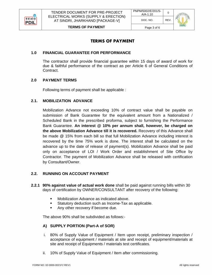
TENDER DOCUMENT FOR PRE-PROJECT
ELECTRICAL WORKS (SUPPLY & ERECTION) AT SINDRI, JHARKHAND [PACKAGE-V]
TERMS OF PAYMENT
PNPM/5002/E/201/S-A/A-1.10 0
DOC. NO. REV.
Page 3 of 6
FORM NO: 02-0000-0021F2 REV1 All rights reserved
TERMS OF PAYMENT
1.0 FINANCIAL GUARANTEE FOR PERFORMANCE
The contractor shall provide financial guarantee within 15 days of award of work for due & faithful performance of the contract as per Article 6 of General Conditions of Contract.
2.0 PAYMENT TERMS
Following terms of payment shall be applicable :
2.1. MOBILIZATION ADVANCE
Mobilization Advance not exceeding 10% of contract value shall be payable on submission of Bank Guarantee for the equivalent amount from a Nationalized / Scheduled Bank in the prescribed proforma, subject to furnishing the Performance Bank Guarantee. An interest @ 10% per annum shall, however, be charged on the above Mobilization Advance till it is recovered. Recovery of this Advance shall be made @ 15% from each bill so that full Mobilization Advance including interest is recovered by the time 75% work is done. The interest shall be calculated on the advance up to the date of release of payment(s). Mobilization Advance shall be paid only on acceptance of LOI / Work Order and establishment of Site Office by Contractor. The payment of Mobilization Advance shall be released with certification by Consultant/Owner.
2.2. RUNNING ON ACCOUNT PAYMENT
2.2.1 90% against value of actual work done shall be paid against running bills within 30 days of certification by OWNER/CONSULTANT after recovery of the following:
Mobilization Advance as indicated above. Statutory deduction such as Income-Tax as applicable. Any other recovery if become due.
The above 90% shall be subdivided as follows:- A) SUPPLY PORTION (Part-A of SOR)
i. 80% of Supply Value of Equipment / Item upon receipt, preliminary inspection /
acceptance of equipment / materials at site and receipt of equipment/materials at site and receipt of Equipments / materials test certificates.
ii. 10% of Supply Value of Equipment / Item after commissioning.
TENDER DOCUMENT FOR PRE-PROJECT
ELECTRICAL WORKS (SUPPLY & ERECTION) AT SINDRI, JHARKHAND [PACKAGE-V]
TERMS OF PAYMENT
PNPM/5002/E/201/S-A/A-1.10 0
DOC. NO. REV.
Page 4 of 6
FORM NO: 02-0000-0021F2 REV1 All rights reserved
B) INSTALLATION, TESTING & COMMISSIONING (Part-B of SOR)
i. 80% of Erection / Installation Value of Equipment / Item after completion of
erection / installation.
ii. 10% of Erection / Installation Value of Equipment / Item after testing and commissioning.
C) CIVIL WORKS (Part-C of SOR)
i. 90% against value of actual work done shall be paid against running bills duly certified by Owner/Consultant.
2.2.2 Balance 10% (Retention Money) for Part-A, B & C of the SOR shall be released along with final bill subject to the following:
The status of the contractor as L-1 bidder shall be ensured keeping in view the final executed Bill of Quantity. All the valid tenders considered in evaluation at the time of award of work shall be re-evaluated at the respective quoted rate with a view to assess whether L-1 contractor’s price of completed works continues to be the lowest. In case after such re-evaluation, final contract value is not the lowest, the contractor shall reimburse to Owner the difference in the amount between the re-evaluated tender and the lowest tendered amount. This difference of amount shall be adjusted from their final bill. However, if the amount recoverable exceeds the amount payable in final bill, the balance amount shall be recovered by the Owner, from the retention money and or performance bank guarantee / any other moneys or bank guarantees available with the Owner for any other job being done by the contractor. The contractor shall restore the performance guarantee to the requisite value to the extent of 10% of contract price in such case where recovery is required to be affected by the encashment as soon as the contractor receives such intimation from the owner / consultant.
2.2.3 OPERATION & MAINTENANCE OF SUBSTATION (Part-D of SOR) 100% payment against the following heads shall be released after receipt of invoice, duly supported with all necessary documents which shall be certified by Engineer In charge: i. Monthly wages of personnel deployed ii. Contractor’s Service Charges
2.3. The running on A/c Bills shall be submitted on monthly basis.

TENDER DOCUMENT FOR PRE-PROJECT
ELECTRICAL WORKS (SUPPLY & ERECTION) AT SINDRI, JHARKHAND [PACKAGE-V]
TERMS OF PAYMENT
PNPM/5002/E/201/S-A/A-1.10 0
DOC. NO. REV.
Page 5 of 6
FORM NO: 02-0000-0021F2 REV1 All rights reserved
2.4. RELEASE OF Ist R/A BILL
Payment will be released against Ist R/A bill only on submission of following documents by contractor to the indenting department.
i. Financial Guarantee for Performance ii. Labour License (as per statutory requirements) iii. EPF Code Registration number with RPFC/ARPFC iv. Insurance Contractor All Risk (CAR) Policy v. Workmen compensation policy
2.5. SUBMISSION OF FINAL BILL The final bill complete in all respect shall be submitted after certified completion of work. The bill should be accompanied with the following documents: i. Job completion certificate. ii. No claim certificate on HURL’s prescribed proforma. iii. Site clearance certificate. iv. Performance guarantee duly amended to cover certified maintenance period. v. Indemnity certificate towards labours payment and all other statutory payments. No claim shall be entertained after receipt of final bill. Settlement of final bill shall be made within 1 (one) month period subject to furnishing of all required documents / clarification and extension of time, if any, by HURL’s competent authority.
3.0 PRICE The prices shall be firm during the entire contract period including all extensions granted on whatsoever ground may be.
4.0 INSTRUCTION FOR INVOICING & PAYMENT DOCUMENTATION
4.1. INVOICING Invoicing shall be in compliance with the stipulations of the Work Order and the following instructions. Contractor is liable for all costs arising from noncompliance with the instructions. As far as possible, description of Works in invoice shall match the description in Work Order. Invoice for payment shall be addressed to Owner.

TENDER DOCUMENT FOR PRE-PROJECT
ELECTRICAL WORKS (SUPPLY & ERECTION) AT SINDRI, JHARKHAND [PACKAGE-V]
TERMS OF PAYMENT
PNPM/5002/E/201/S-A/A-1.10 0
DOC. NO. REV.
Page 6 of 6
FORM NO: 02-0000-0021F2 REV1 All rights reserved
The invoices shall be issued in the name of:
HINDUSTAN URVARAK & RASAYAN LIMITED,
CORE-2, 2nd FLOOR, SCOPE MINAR, LAXMI NAGAR DISTRICT CENTRE, DELHI-92 ATTN : MR. D S SAHU
DY. GENERAL MANAGER (PROJECTS) TEL NO. : 011-22502267 EMAIL : [email protected]
The invoice shall contain the following information:
i. Work Order No. ii. Item no., quantity and complete description iii. Item-wise net price (unit and total) of the works where applicable. iv. Net amount payable by deducting advance payment already invoiced, if any,
and the guarantee retention amount, if any, from the total value of the Works being invoiced.
The signed invoices, original and copy shall be made on Contractor's letter head and shall be duly signed.
Invoices for progress payment(s) shall state the information under (i), (ii) and (iii). Invoices for guarantee retention money shall state the information under (i) to (iv).
4.2. PROGRESS PAYMENT 1) Invoice for ________________ in original and two (2) copies duly certified by
Owner / Consultant.
2) Performance certificate in one (1) original plus two (2) copies from the beneficiary to the effect that progress achieved is equal to progress invoiced, duly certified by Owner/Consultant.
TENDER DOCUMENT FOR PRE-PROJECT ELECTRICAL WORKS (SUPPLY & ERECTION)
AT SINDRI, JHARKHAND [PACKAGE-V]
PROFORMA OF BANK GUARANTEE FOR EARNEST MONEY DEPOSIT (EMD) / BID SECURITY
PNPM/5002/E/201/S-A/AT-1.11 0
DOC. NO. REV.
Page 1 of 3
FORM NO: 02-0000-0021F2 REV3 All rights reserved
SECTION-A : COMMERCIAL
ATTACHMENT - 1.11
PROFORMA OF BANK GUARANTEE FOR EARNEST MONEY DEPOSIT (EMD) / BID SECURITY
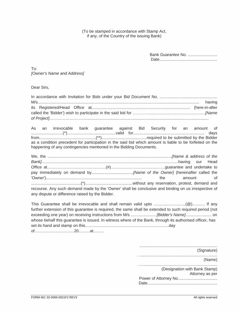
FORM NO: 02-0000-0021F2 REV3 All rights reserved
(To be stamped in accordance with Stamp Act, if any, of the Country of the issuing Bank)
Bank Guarantee No. .......................... Date...................................................
To: [Owner's Name and Address] Dear Sirs, In accordance with Invitation for Bids under your Bid Document No. ................................................... M/s............................................................................................................................................... having its Registered/Head Office at....................................................................................... (here-in-after called the 'Bidder') wish to participate in the said bid for …………..................................................[Name of Project]……………………................................................................................................................ As an irrevocable bank guarantee against Bid Security for an amount of ............................(*)...........................................valid for............................................................... days from..................................................(**)........................................required to be submitted by the Bidder as a condition precedent for participation in the said bid which amount is liable to be forfeited on the happening of any contingencies mentioned in the Bidding Documents. We, the ..............................................................................................................[Name & address of the Bank].........................................................................................................................having our Head Office at....................................................(#)................................................guarantee and undertake to pay immediately on demand by.....................................[Name of the Owner] (hereinafter called the 'Owner')..................................................................................... the amount of ............................................(*)..........................................without any reservation, protest, demand and recourse. Any such demand made by the 'Owner' shall be conclusive and binding on us irrespective of any dispute or difference raised by the Bidder. This Guarantee shall be irrevocable and shall remain valid upto ............................(@)........... If any further extension of this guarantee is required, the same shall be extended to such required period (not exceeding one year) on receiving instructions from M/s ...................... [Bidder's Name]....................... on whose behalf this guarantee is issued. In witness where of the Bank, through its authorised officer, has set its hand and stamp on this..........................................................................day of...................................20..........at.........
..................................................................... (Signature)
. ..................................................................... (Name)
. ..................................................................... (Designation with Bank Stamp)
Attorney as per Power of Attorney No................................... Date..............................................................
FORM NO: 02-0000-0021F2 REV3 All rights reserved
NOTE : 1. (*) The amount shall be as specified in Letter Inviting Bid.
(**) This shall be the date of opening of Technical and Commercial bids. (#) Complete mailing address of the Head Office of the Bank to be given. (@) This date shall be three (3) months beyond bid valid.
2. The Stamp Paper of appropriate value shall be purchased in the name of Bidder / Bank issuing
the guarantee.
TENDER DOCUMENT FOR PRE-PROJECT
ELECTRICAL WORKS (SUPPLY & ERECTION) AT SINDRI, JHARKHAND [PACKAGE-V]
PROFORMA OF SECURITY CUM PERFORMANCE BANK GUARANTEE / SECURITY DEPOSIT
PNPM/5002/E/201/S-A/A-1.12 0
DOC. NO. REV.
Page 1 of 3
FORM NO: 02-0000-0021F2 REV3 All rights reserved
SECTION-A : COMMERCIAL
ATTACHMENT - 1.12
PROFORMA OF SECURITY CUM PERFORMANCE BANK GUARANTEE / SECURITY DEPOSIT
FORM NO: 02-0000-0021F2 REV3 All rights reserved
(To be submitted on non judicial stamp paper of appropriate value)
PROFORMA OF BANK GUARANTEE FOR CONTRACT PERFORMANCE
(This guarantee should be executed on non-judicial stamp paper of appropriate value)
In Consideration of Hindustan Urvarak & Rasayan Limited, having its Registered Office at Coal Bhawan, 10, Netaji Subhash Marg, Kolkata-700001, (hereinafter referred to as the `owner' which expression shall unless repugnant to the context or meaning thereof include its successors, administrators and assigns) having awarded to M/s. ___________________________ with its registered/Head Office at __________________ (hereinafter referred to as the `Contractor' which expression shall unless repugnant to the context or meaning thereof, include its successors, administrators, executors and assigns), a Contract by issue of Owner's Letter of Intent No. _________ dated __________ and the same having been unequivocally accepted by the Contractor, resulting in a contract _____________( scope of contract ) ___________ and the Contractor having agreed to provide a Contract Performance Guarantee for the faithful performance of the entire Contract equivalent to Rs. ________ (%) ______ per cent) of the said value of the Contract to the Owner. We _________________ (name and address)_____________ having its Head Office at _______________________ (hereinafter referred to as the `Bank' which expression shall, unless repugnant to the context or meaning thereof, include it successors, administrators, executors and assigns) do hereby guarantee and undertake to pay the Owner, on demand any and all monies payable by the Contractor to the extent of ________________ as aforesaid at anytime upto _____________________ (days/month/year) without any demur, reservation, context, recourse or protest and/or without any reference to the Contractor. Any such demand made by the Owner on the Bank shall be conclusive and binding notwithstanding any difference between the Owner and the Contractor or any dispute pending before any Court, Tribunal, Arbitrator or any other authority. The Bank undertakes not to revoke this guarantee during its currency without previous consent of the Owner and further agrees that the guarantee herein contained shall continue to be enforceable till the Owner discharge this guarantee. The Owner shall have the fullest liberty without affecting in any way the liability of the Bank under this guarantee, from time to time to extend the time for performance of the Contract by the Contractor. The Owner shall have the fullest liberty, without affecting this guarantee, to postpone from time to time the exercise of any powers vested in them or of any right which they might have against the Contractor, and to exercise the same at any time in any manner, and either to enforce or to forbear to enforce any covenants, contained or implied, in the contract between the Owner and the Contractor or any other course or remedy or security available to the Owner. The bank shall not be released to its obligations under these presents by any exercise by the Owner of its liberty with reference to the matters aforesaid or any of them or by reason of any other act of omission or commission on the part of the Owner or any other
FORM NO: 02-0000-0021F2 REV3 All rights reserved
indulgences shown by the Owner or by any other matter or thing whatsoever which under law would, but for this provision have the effect of relieving the Bank. The Bank also agrees that the Owner at its option shall be entitled to enforce this Guarantee against the Bank as a principal debtor, in the first instance without proceeding against the Contractor and notwithstanding any security or other guarantee the Owner may have in relation on to the Contractor's liabilities. Notwithstanding anything contained herein above our liability under this guarantee is restricted to Rs. ________ and it shall remain in force upto till _________. Unless a demand or claim under this performance bond is filed against us within six months from the expiry date of this Guarantee, i.e. on or before ______________ all the rights under this performance bond shall be forfeited and we shall be relieved and discharged from all liability there under. IN WITNESS, the Principal and surety have executed this performance bond and have affixed their seals on the date set forth. Dated this ______ ____ day of _________ 200 ___ at ________. PRINCIPAL CORPORATE SURETY
TENDER DOCUMENT FOR PRE-PROJECT
ELECTRICAL WORKS (SUPPLY & ERECTION) AT SINDRI, JHARKHAND [PACKAGE-V]
BANK GUARANTEE FOR ADVANCE/ PROGRESS PAYMENT
PNPM/5002/E/201/S-A/A-1.13 0
DOC. NO. REV.
Page 1 of 3
FORM NO: 02-0000-0021F2 REV3 All rights reserved
SECTION-A : COMMERCIAL
ATTACHMENT - 1.13
BANK GUARANTEE FOR ADVANCE / PROGRESS PAYMENT
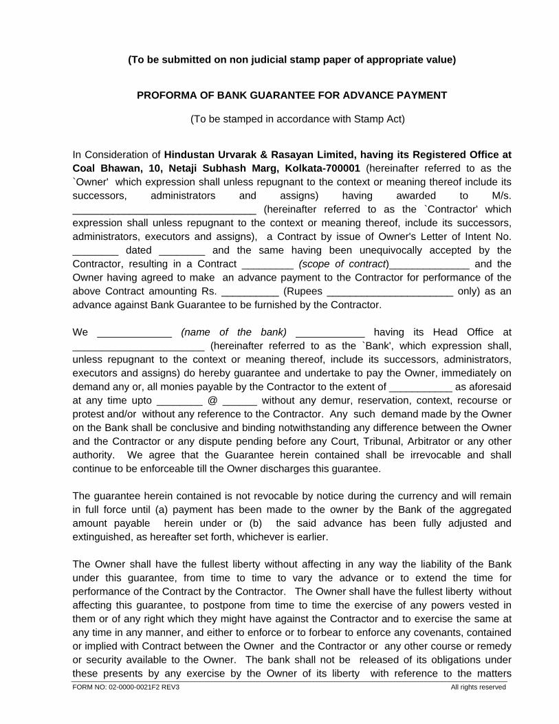
FORM NO: 02-0000-0021F2 REV3 All rights reserved
(To be submitted on non judicial stamp paper of appropriate value)
PROFORMA OF BANK GUARANTEE FOR ADVANCE PAYMENT
(To be stamped in accordance with Stamp Act) In Consideration of Hindustan Urvarak & Rasayan Limited, having its Registered Office at Coal Bhawan, 10, Netaji Subhash Marg, Kolkata-700001 (hereinafter referred to as the `Owner' which expression shall unless repugnant to the context or meaning thereof include its successors, administrators and assigns) having awarded to M/s. ________________________________ (hereinafter referred to as the `Contractor' which expression shall unless repugnant to the context or meaning thereof, include its successors, administrators, executors and assigns), a Contract by issue of Owner's Letter of Intent No. ________ dated ________ and the same having been unequivocally accepted by the Contractor, resulting in a Contract _________ (scope of contract)______________ and the Owner having agreed to make an advance payment to the Contractor for performance of the above Contract amounting Rs. __________ (Rupees ______________________ only) as an advance against Bank Guarantee to be furnished by the Contractor. We _____________ (name of the bank) ____________ having its Head Office at _______________________ (hereinafter referred to as the `Bank', which expression shall, unless repugnant to the context or meaning thereof, include its successors, administrators, executors and assigns) do hereby guarantee and undertake to pay the Owner, immediately on demand any or, all monies payable by the Contractor to the extent of ___________ as aforesaid at any time upto ________ @ ______ without any demur, reservation, context, recourse or protest and/or without any reference to the Contractor. Any such demand made by the Owner on the Bank shall be conclusive and binding notwithstanding any difference between the Owner and the Contractor or any dispute pending before any Court, Tribunal, Arbitrator or any other authority. We agree that the Guarantee herein contained shall be irrevocable and shall continue to be enforceable till the Owner discharges this guarantee. The guarantee herein contained is not revocable by notice during the currency and will remain in full force until (a) payment has been made to the owner by the Bank of the aggregated amount payable herein under or (b) the said advance has been fully adjusted and extinguished, as hereafter set forth, whichever is earlier. The Owner shall have the fullest liberty without affecting in any way the liability of the Bank under this guarantee, from time to time to vary the advance or to extend the time for performance of the Contract by the Contractor. The Owner shall have the fullest liberty without affecting this guarantee, to postpone from time to time the exercise of any powers vested in them or of any right which they might have against the Contractor and to exercise the same at any time in any manner, and either to enforce or to forbear to enforce any covenants, contained or implied with Contract between the Owner and the Contractor or any other course or remedy or security available to the Owner. The bank shall not be released of its obligations under these presents by any exercise by the Owner of its liberty with reference to the matters

FORM NO: 02-0000-0021F2 REV3 All rights reserved
aforesaid or any of them or by reason of any other act or forbearance or other acts of omission or commission on the part of the Owner or any other indulgence shown by the Owner or by any other matter or thing whatsoever which under law would but for this provision have the effect of relieving the Bank.
The Bank also agrees that the Owner at its option shall be entitled to enforce this Guarantee against the Bank as a principal debtor, in the first instance without proceeding against the Contractor and notwithstanding any security or other guarantee that the Owner may have in relation to the Contractor's liabilities. Notwithstanding anything contained herein above our liability under this guarantee is limited to __________ and it shall remain in force upto and including ______ @ ______ and shall be extended from time to time for such period (not exceeding one year), as may be desired by M/s. __________________ on whose behalf this guarantee has been given. Dated this ______ day of _____ 200___ at ___________
TENDER DOCUMENT FOR PRE-PROJECT
ELECTRICAL WORKS (SUPPLY & ERECTION) AT SINDRI, JHARKHAND [PACKAGE-V]
PROFORMA FOR BLACK-LISTED
PNPM/5002/E/201/S-A/A-1.14 0
DOC. NO. REV.
Page 1 of 2
FORM NO: 02-0000-0021F2 REV3 All rights reserved
SECTION-A : COMMERCIAL
ATTACHMENT - 1.14
PROFORMA FOR BLACKLISTED

FORM NO: 02-0000-0021F2 REV3 All rights reserved
(Self Declaration on Bidder’s Letter Head as per below performa)
DECLARATION To , ………………………………. ………………………………. ……………………………… NIT NO. : PNPM/5002/E/201
SUBJECT : TENDER DOCUMENT FOR PRE-PROJECT ELECTRICAL WORKS (SUPPLY &
ERECTION) AT SINDRI, JHARKHAND [PACKAGE-V] Sir , We hereby declare that M/s ……………………………………. is neither put on Holiday or Black-listed by any Government / PSU / Private firm or Financial Institution. Signature Name : Designation : Seal of the Bidder.
TENDER DOCUMENT FOR PRE-PROJECT
ELECTRICAL WORKS (SUPPLY & ERECTION) AT SINDRI, JHARKHAND [PACKAGE-V]
FORMAT OF CONTRACT AGREEMENT
PNPM/5002/E/201/S-A/A-1.15 0
DOC. NO. REV.
Page 1 of 4
FORM NO: 02-0000-0021F2 REV3 All rights reserved
SECTION-A : COMMERCIAL
ATTACHMENT - 1.15
FORMAT OF CONTRACT AGREEMENT

FORM NO: 02-0000-0021F2 REV3 All rights reserved
FORMAT OF CONTRACT AGREEMENT
(To be executed on non-judicial stamp paper of appropriate value)
THIS CONTRACT AGREEMENT is made the________________day of___________, 20____. BETWEEN (1) [Name of Owner], a corporation incorporated under the laws of India and having its principal place of business at [address of Owner] (hereinafter called “the Owner”), and (2) [name of Contractor], a corporation incorporated under the laws of India and having its principal place of business at [address of Contractor] (hereinafter called “the Contractor”) WHEREAS the Owner desires to engage the Contractor to ……………..[scope of work]……….. and the Contractor have agreed to such engagement upon and subject to the terms and conditions hereinafter appearing. NOW IT IS HEREBY AGREED as follows:
ARTICLE 1. CONTRACT DOCUMENTS
1.1 The following documents shall constitute the Contract between the Owner and the Contractor,
and each shall be read and construed as an integral part of the Contract:
a) This Contract Agreement and the Appendices hereto b) Letter of Award c) Amendment to the NIT document. d) Instruction to Bidders e) Special Conditions of Contract f) General Conditions of Contract g) Technical Specifications and Drawings h) The Bid and Schedule of Prices including Supplementary Price (delete if not applicable)
submitted by the Contractor i) Integrity Pact (IP) signed between the Owner and the Bidder / Contractor
1.2 Order of Precedence
In the event of any ambiguity or conflict between the Contract Documents listed above, the order of precedence shall be the order in which the Contract Documents are listed in Article 1.1 (Contract Documents) above.
1.3 Definitions
Capitalized words and phrases used herein shall have the same meanings as are ascribed to them in the General Conditions of Contract.
ARTICLE 2. CONTRACT PRICE AND PAYMENT TERMS 2.1 Contract Price
The Owner hereby agrees to pay to the Contractor the Contract Price in consideration of the performance by the Contractor of its obligations hereunder. The Contract Price shall be the and [amount in words], [amount in figures], or such other sums as may be determined in accordance with the terms and conditions of the Contract.

FORM NO: 02-0000-0021F2 REV3 All rights reserved
2.2 Payment Terms
Payment shall be made by the Owner to the Contractor as per the provisions of Bidding Documents.
ARTICLE 3. EFFECTIVE DATE FOR DETERMINING TIME FOR COMPLETION
The Completion period of the Project shall be determined from the date of Letter of Award.
ARTICLE 4. NON-ASSIGNABILITY
The Contract and benefits and obligations thereof shall be strictly personal to the CONTRACTOR
and shall not on any account be assignable or transferable by the CONTRACTOR.
ARTICLE 5. GOVERNMENT OF INDIA NOT LIABLE
It is expressly understood and agreed by and between the Contractor and the Owner that the Owner is entering into this Agreement solely on its own behalf and not on behalf of any other person or entity. In particular it is expressly understood and agreed that the Government of India is not a party to this Agreement and has no liabilities, obligations or rights hereunder. It is expressly understood and agreed that the Owner is an Independent legal entity with power and authority to enter into contracts solely on its own behalf under the applicable laws of India and the general principles of Contract Law. The Contractor expressly agrees, acknowledges and understands that the Owner is not an Agent, Representative or Delegate of the Govt. of India. It is Further understood and agreed that the Government of India is not and shall not be liable for any acts, omissions, commissions, breaches or other wrongs arising out of the Contract. Accordingly, the Contractor expressly waives, releases and foregoes any and all actions or claims, inlcuding cross claims, impleader claims or counter claims against the Government of India arising out of this Contract and covenants not to sue the Government of India as to any manner, claim, cause of action or thing whatsoever arising of or under this Contract.
ARTICLE 6. APPENDICES
The Appendices listed in the attached list of Appendices shall be deemed to form an integral part of this Contract Agreement. Reference in the Contract to any Appendix shall mean the Appendices attached hereto, and the Contract shall be read and construed accordingly.
ARTICLE 7. NO LIABILITY ON DIRECTOR AND EMPLOYEE
No Director, employee, consultant or agent of the OWNER or other person representing the OWNER or acting on behalf of the OWNER in or pursuant to the Contract or in the discharge of any obligation to the OWNER under the Contract or otherwise in relation to the Contract shall have any personal liability to the CONTRACTOR or any Sub-Contractor, agent, representative, director or employee of the CONTRACTOR or to any other person acting for or on behalf of the CONTRACTOR and the CONTRACTOR on its own behalf and on behalf of its Sub Contractors, directors, employees, agents and representatives hereby waives and disclaims any and all right of action which it or they may have whether under tort or Contract or otherwise against the OWNER or any director, employee, agent, consultant or representative of the OWNER for act of omission or commission done or omitted to be done.
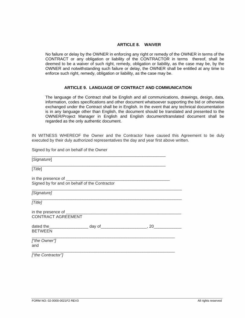
FORM NO: 02-0000-0021F2 REV3 All rights reserved
ARTICLE 8. WAIVER
No failure or delay by the OWNER in enforcing any right or remedy of the OWNER in terms of the CONTRACT or any obligation or liability of the CONTRACTOR in terms thereof, shall be deemed to be a waiver of such right, remedy, obligation or liability, as the case may be, by the OWNER and notwithstanding such failure or delay, the OWNER shall be entitled at any time to enforce such right, remedy, obligation or liability, as the case may be.
ARTICLE 9. LANGUAGE OF CONTRACT AND COMMUNICATION
The language of the Contract shall be English and all communications, drawings, design, data, information, codes specifications and other document whatsoever supporting the bid or otherwise exchanged under the Contract shall be in English. In the event that any technical documentation is in any language other than English, the document should be translated and presented to the OWNER/Project Manager in English and English document/translated document shall be regarded as the only authentic document.
IN WITNESS WHEREOF the Owner and the Contractor have caused this Agreement to be duly executed by their duly authorized representatives the day and year first above written. Signed by for and on behalf of the Owner __________________________________________________________ [Signature] __________________________________________________________ [Title] in the presence of _____________________________________________ Signed by for and on behalf of the Contractor _________________________________________________________________ [Signature] _________________________________________________________________ [Title] in the presence of __________________________________________________ CONTRACT AGREEMENT dated the_________________ day of____________________, 20____________ BETWEEN ______________________________________________________________ [“the Owner”] and ______________________________________________________________ [“the Contractor”]
TENDER DOCUMENT FOR PRE-PROJECT
ELECTRICAL WORKS (SUPPLY & ERECTION) AT SINDRI, JHARKHAND [PACKAGE-V]
DECLARATION BY BIDDER REGARDING BIDDING DOCUMENT
PNPM/5002/E/201/S-A/A-1.16 0
DOC. NO. REV.
Page 1 of 2
FORM NO: 02-0000-0021F2 REV3 All rights reserved
SECTION-A : COMMERCIAL
ATTACHMENT - 1.16
DECLARATION BY BIDDER REGARDING BIDDING DOCUMENT
All rights reserved
(Declaration on Bidder’s Letter Head as per below performa) SUBJECT: TENDER DOCUMENT FOR PRE-PROJECT ELECTRICAL WORKS (SUPPLY &
ERECTION) AT SINDRI, JHARKHAND [PACKAGE-V] We _______________________ (Name of the Bidder) hereby represent that we have gone through and
understood the Bidding Documents, NIT NO: PNPM/5002/E/201 DATED 30.01.2018 (including but not
limited to) the Commercial & Technical Requirements/ Specifications in Section-A : Commercial and
Section-B : Technical of the Bidding documents and amendments, if any, and that our Bid has been
prepared accordingly in compliance with the requirements stipulated in the said documents.
We are submitting a copy of complete set of Bidding Documents, Section-A : Commercial and
Section-B : Technical and amendments, if any, as part of our Bid duly signed and stamped on each
page in token of our acceptance. Further we undertake that in the event of award of work to us, all the
parts shall be considered for constitution of Contract Agreement.
For and on behalf of : ……………...........…………………
Stamp & Signature : ………………………………………
Name : ………………………………………
Designation : ………………………………………
Date : ………………………………………
TENDER DOCUMENT FOR PRE-PROJECT
ELECTRICAL WORKS (SUPPLY & ERECTION) AT SINDRI, JHARKHAND [PACKAGE-V]
FORMAT FOR INTEGRITY PACT
PNPM/5002/E/201/S-A/A-1.17 0
DOC. NO. REV.
Page 1 of 8
SECTION-A : COMMERCIAL
ATTACHMENT - 1.17
FORMAT FOR INTEGRITY PACT
FORM NO: 02-0000-0021F2 REV3 All rights reserved
INTEGRITY PACT
This pre-bid pre-contract Agreement (hereinafter called the Integrity Pact) is made on ____ day of the month of _____________ 2017, between M/s Hindustan Urvarak & Rasayan Ltd., registered under Companies Act, 2013, having its registered office at having its Registered Office at Coal Bhawan, 10, Netaji Subhash Marg, Kolkata-700001 (hereinafter referred to as [HURL], which expression shall mean and include, unless the context otherwise requires, its successors and assigns) of the First Part and M/s ______________________________________ a Company, firm incorporated under _________________________________________ Laws to which it is subject to (hereinafter called the “Bidder/Seller”, which expression shall mean and include, unless the context otherwise requires, its successors, heirs / legal representatives / administrator in office and assigns) of the Second Part. Whereas HURL has issued NIT__________________ dated__________ inviting bids from Parties for undertaking-the Project /Work of_______________________________________ at its unit located at__________________________________________________________ (hereinafter referred to as the Project /Work). The BIDDER is a private Company/Public Company/Government Undertaking / Partnership / registered export agency, constituted in accordance with the relevant law in the matter and HURL is joint venture company incorporated by Indian Oil Corporation Ltd. (IOCL), National Thermal Power Corporation Ltd. (NTPC), Coal India Ltd. (CIL), The Fertilizer Corporation of India Ltd. (FCIL) and Hindustan Fertiliser Corporation Ltd. (HFCL). The Bidder is willing to offer/ has offered to carry out the Project/ Work and understands that this Integrity Pact has to be executed between the parties before HURL can consider the offer. NOW, THEREFORE, To avoid all forms of corruption by following a system that is fair, transparent and free from any influence/prejudiced dealings prior to, during and subsequent to the currency of the contract to be entered into with a view to :- Enabling HURL to undertake the Project/Work at a competitive price in conformity with the defined specifications by avoiding the high costs and the distort nary impact of corruption on public procurement, and Enabling BIDDER to abstain from bribing or indulging in any corrupt practices in order to secure the contract by providing assurance to them that their competitors will also abstain from bribing and other corrupt practices and HURL will commit to prevent corruption, in any form, by its officials by following transparent procedures. In respect of the Project/Work an Independent Monitor shall be appointed by HURL to verify facts and to take necessary action, legal or otherwise as may be deemed appropriate including criminal proceedings, against the persons and /or Organizations indulging in the corrupt practice. NOW, THEREFORE IN CONSIDERATION OF THE MUTUAL COVENANTS CONTAINED HEREIN, THE PARTIES AGREE AS UNDER:
FORM NO: 02-0000-0021F2 REV3 All rights reserved
1.0 COMMITMENTS OF HURL: 1.1 HURL undertakes that no official of HURL, connected directly or indirectly with the Project/Work,
will demand, take a promise for or accept, directly or through intermediaries, any bribe, consideration, gift, reward, favour or any material or immaterial benefit or any other advantage from the BIDDER, either for themselves or for any other person, organization or third party related to the contract in exchange for an advantage in the bidding process, bid evaluation, contracting or implementation process related to the contract.
1.2 HURL will, during the pre-contract stage, treat all BIDDERs alike, and will provide to all BIDDERs
the same information and will not provide any such information to any particular BIDDER which could afford an advantage to that particular Bidder in comparison to other BIDDERs.
1.3 HURL will report to the Independent Monitor of any attempted or completed breaches of the
above commitments as well as any substantial suspicion of such a breach. HURL will also report to appropriate Government Office wherever necessary”.
2.0 PRECEDING MISCONDUCT: 2.1 In case any preceding misconduct on the part of any official(s) is reported by the BIDDER to the
Independent Monitor with full and verifiable facts and the same is prima facie found to be correct by the Independent Monitor, necessary disciplinary proceedings, or any other action as deemed fit, including criminal proceedings may be initiated by HURL or the Independent Monitor and such a person shall be debarred from further dealings related to contract process. In such a case while an enquiry is being conducted by HURL the proceedings under the contract would not be stalled.
3.0 COMMITMENTS OF BIDDER: 3.1 The BIDDER commits itself to take all measures necessary to prevent corrupt practices, unfair
means and illegal activities during any stage of its bid or during any pre-contract or post-contract stage in order to secure the contract or in furtherance to secure it and in particular commit itself to the following:
3.2 The BIDDER will not offer, directly or through intermediaries, any bribe, gift, consideration,
reward, favour, any material or immaterial benefit or other advantage, commission, fees, brokerage or inducement to any official of the HURL, connected directly or indirectly with the bidding process, or to any person, organization or third party related to the contract in exchange for any advantage in the bidding, evaluation, contracting and implementation of the contract.
3.3 The BIDDER further undertakes that it has not given, offered or promised to give, directly or
indirectly any bribe, gift, consideration, reward, favour, any material or immaterial benefit or other advantage, commission, fees, brokerage or inducement to any official of HURL or otherwise in procuring the Contract or forbearing to do or having done any act in relation to the obtaining or execution of the contract or any other contract with HURL for showing or forbearing to show favour or disfavour to any person in relation to the contract or any other contract with HURL.
3.4 BIDDER shall disclose the name(s) and address(es) of foreign principals, associates, agents and
distributors, advisors, representatives and sub-contractors.
FORM NO: 02-0000-0021F2 REV3 All rights reserved
3.5 BIDDER shall disclose the payments to be made by them to agents/ brokers or any other intermediary, in connection with this bid/ contract.
3.6 The BIDDER further confirms and declares to HURL that he has not engaged any individual or
firm or company, whether Indian or foreign, to intercede, facilitate or in any way to recommend to HURL or any or its functionaries, whether officially or unofficially to the award of the contract to the BIDDER, nor has any amount been paid, promised or intended to be paid to any such individual, firm or Company in respect of any such intercession, facilitation or recommendation.
3.7 The BIDDER, either while presenting the bid or during pre-contract negotiations or before signing
the contract, shall disclose complete details of any payments made, is committed to or intends to make to any officials of HURL or their family members, agents, brokers or any other intermediaries in connection with the contract and the details of services agreed upon for such payments.
3.8 The BIDDER will not collude with other parties, interested in the contract, to impair the
transparency, fairness and progress of the bidding process, bid evaluation, contracting and implementation of the contract.
3.9 The BIDDER will not accept any advantage in exchange for any corrupt practice, unfair means
and illegal activities. 3.10 The BIDDER shall not use improperly, for purposes of completion or personal gain, or pass on to
others, any information provided by HURL as part of the business relationship, such as plans, technical proposals and business details including information contained in any electronic data carrier. The BIDDER also undertakes to exercise due and adequate care to ensure that no information is divulged to others.
3.11 The BIDDER commits to refrain from giving any complaint in connection with the Project, directly
or through any other manner, without supporting it with full and verifiable facts. 3.12 The BIDDER shall not instigate or cause to instigate any third party to commit any of the actions
aforestated. 3.13 If the BIDDER or any employee of the BIDDER or any person acting on behalf of the BIDDER,
either directly or indirectly, is a relative of any of the employees of HURL, or, if any relative of an employee of HURL has financial interest/stake in the BIDDER, the same shall be disclosed by the BIDDER at the time of filing the tender.
The term `relative’ for this purpose would be as defined in Companies Act, 2013 or any modifications thereof.
3.14 The BIDDER shall not lend to or borrow any money from or enter into any monetary dealings or
transactions, directly or indirectly, with any employee of HURL. 4.0 PREVIOUS TRANSGRESSION 4.1 The BIDDER declares that no previous transgression occurred in the last three years
immediately before signing of this Integrity Pact with HURL, in respect of any corrupt practices
FORM NO: 02-0000-0021F2 REV3 All rights reserved
envisaged hereunder, and/or with any Public Sector Enterprises/ Government department that could justify BIDDERs exclusion from the tender process.
4.2 The BIDDER agrees that if it makes incorrect statement on this subject, BIDDER can be
disqualified from the tender process of the contract, and if already awarded, the Contract can be terminated for such reason.
5.0 EARNEST MONEY / SECURITY DEPOSIT: 5.1 While submitting commercial bid, the BIDDER shall deposit an amount ____________________
as Earnest Money/Security Deposit, with HURL through any of the following instruments:
(i) Bank draft or pay order in favour of
(ii) A confirmed guarantee by an Indian Nationalized Bank, promising payment of the guaranteed sum to the Buyer on demand within three working days without any demur whatsoever and without seeking any reasons whatsoever. The demand for payment by the Buyer shall be treated as conclusive proof of payment
(iii) Any other mode or through any other instrument
5.2 The amount and validity of the earnest money / Security Deposit shall be as mentioned in the
NIT. 5.3 In case of the successful BIDDER a clause would also be incorporated in the Article pertaining to
Performance Bond in the purchase contract that the provisions of Sanctions for Violation shall be applicable for forfeiture of Performance Bond in case of the decision by the BUYER to forfeit the same without assigning any reason for imposing sanction for violation of this Pact.
5.4 No interest shall be payable by the HURL to the BIDDER on Earnest Money/ Security Deposit for
the period of its currency. 6.0 SANCTIONS FOR VIOLATIONS 6.1 Any breach of the aforesaid provisions by the BIDDER or any one employed by it or acting on its
behalf (whether with or without the knowledge of the BIDDER or any one employed by it or acting on its behalf (whether with or without the knowledge of the BIDDER) shall entitle HURL to take all or any one of the following actions, wherever required:-
i. To immediately call off the pre contract negotiations without assigning any reason or giving any compensation to the BIDDER. However, the proceedings with the other BIDDER(s) would continue.
ii. The Earnest Money Deposit (in pre-contract stage) and /or Security Deposit/Performance Bond (after the contract is signed) shall stand forfeited either fully or partially, as decided by HURL, without assigning any reason thereof.
iii. To immediately cancel the contract, if already signed, without giving any compensation to the BIDDER.
FORM NO: 02-0000-0021F2 REV3 All rights reserved
iv. To recover all sums already paid by HURL, together with interest thereon at 2% higher than the prevailing Lending Rate of State Bank of India or at 2% higher than LIBOR as may be applicable based on whether the bidder is an Indian party or a foreign party. If any outstanding payment is due to the BIDDER from HURL in connection with any other contract for any other Project/Work/ Supply, such outstanding payment could also be utilized to recover the aforesaid sum and interest. v. To encash the advance bank guarantee and performance bond/ warranty bond, if furnished by the BIDDER, in order to recover the payments, already made by HURL, along with interest. vi. To terminate all or any other Contracts with the BIDDER. The BIDDER shall be liable to pay compensation for any loss or damage to HURL resulting from such termination and RCF shall be entitled to deduct the amount so payable from the money(s) due to the BIDDER.
vii. To debar/blacklist the BIDDER from participating in future bidding processes of HURL for a minimum period of five years, which may be further extended at the discretion of HURL. viii. To recover all sums paid, in violation of this Pact by BIDDER to any middleman or agent or broker, with a view to securing the contract. ix. In case where irrevocable Letters of Credit have been opened in respect of any contract signed by HURL with the BIDDER, the same shall not be operated. x. Forfeiture of Performance Bond in case of a decision by HURL to forfeit the same without assigning any reason for imposing sanction for violation of this Pact.
6.2 HURL will be entitled to take all or any of the actions mentioned at para 6.1 (i) to (x) of this Pact
also on the Commission by the BIDDER or any one employed by it or acting on its behalf (Whether with or without the knowledge of the BIDDER) of an offence as defined in Chapter IX of the Indian Penal code, 1860 or Prevention of Corruption Act, 1988 or any other statute enacted for prevention of corruption.
6.3 The decision of HURL to the effect that a breach of the provisions of this Pact has been
committed by the BIDDER shall be final and conclusive on the BIDDER. However, the Bidder can approach the Independent Monitor appointed for the purposes of this Pact.
7.0 INDEPENDENT MONITOR: 7.1 HURL has appointed following persons as Independent Monitor for this Pact:
(i) Name :. …………
Address: Email: Mobile:
(ii) Name :. …………
Address: Email: Mobile:
FORM NO: 02-0000-0021F2 REV3 All rights reserved
7.2 The task of the Monitor shall be to review independently and objectively, whether and to what
extent the parties comply with the obligations under this Pact. 7.3 The Monitor shall not be subject to instructions by the representatives of the parties and perform
his functions neutrally and independently. 7.4 Both the parties accept that the Monitor has the right to access all the documents relating to the
project/ procurement, including minutes of meetings. 7.5 As soon as the Monitor notices, or has reason to believe a violation of this Pact, he will so inform
the Authority designated by HURL. 7.6 Notwithstanding any Confidentiality Agreement/ clause agreed between HURL and Bidder, the
BIDDER accepts that the Monitor has the right to access, without restriction, to all Project documentation of HURL including that provided by the BIDDER. The BIDDER will also grant the Monitor, upon his request and demonstration of a valid interest, unrestricted and unconditional access to this project documentation. The same is applicable to Subcontractors. The Monitor shall be under contractual obligation to treat the information and documents of the BIDDER/ Subcontractor (s) with confidentiality.
7.7 HURL will provide to the Monitor sufficient information about all meetings among the parties
related to the supply provided such meetings could have an impact on the contractual relations between the parties. The parties will offer to the Monitor the option to participate in such meetings.
7.8 The Monitor will submit a written report to the designated Authority of HURL within 8 to 10 weeks
from the date of reference or intimation to him by HURL/ BIDDER and should the occasion arise, submit proposals for correcting problematic situations.
8.0 FACILITATION OF INVESTIGATION
In case of any allegation of violation of any provisions of these terms or payment of commission, HURL shall be entitled to examine all the project documents of the BIDDER and the BIDDER shall provide necessary information and documents in English and shall extend all possible help for the purpose of such examination.
9.0 LAW AND PLACE OF JURISDICTION
This Pact is subject to Indian Law. The place of performance and jurisdiction is the registered office of HURL.
10.0 OTHER LEGAL ACTIONS
The Actions stipulated in this Integrity Pact are without prejudice to any other legal action that may follow in accordance with the provisions of the extant law in force relating to any civil or criminal proceedings.
11.0 VALIDITY
FORM NO: 02-0000-0021F2 REV3 All rights reserved
11.1 The validity of this Integrity Pact shall be from date the NIT is issued and extend upto two years from the date of last payment under the contract. In case BIDDER is not awarded Contract/Purchase Order, this Integrity Pact shall expire after twelve months from the date of issue of the NIT.
11.2 Should one or several provisions of this Pact turn out to be invalid, the remainder of this Pact
shall remain valid. In this case, the parties will strive to come to an agreement to their original intentions.
12.0 The parties hereby sign this Integrity Pact, through their authorized representative, for having
accepted the conditions contained hereinabove. HURL BIDDER ( ) ( ) Date: Date: Place: Place: Witness Witness 1. ________________ 1. ____________________ 2. ________________ 2. ____________________

TENDER DOCUMENT FOR PRE-PROJECT
ELECTRICAL WORKS (SUPPLY & ERECTION) AT SINDRI, JHARKHAND [PACKAGE-V]
PROFORMA FOR SOLVENCY CERTIFICATE
PNPM/5002/E/201/S-A/A-1.18 0
DOC. NO. REV.
Page 1 of 2
FORM NO: 02-0000-0021F2 REV3 All rights reserved
SECTION-A : COMMERCIAL
ATTACHMENT - 1.18
PROFORMA FOR SOLVENCY CERTIFICATE

TENDER DOCUMENT FOR PRE-PROJECT
ELECTRICAL WORKS (SUPPLY & ERECTION) AT SINDRI, JHARKHAND [PACKAGE-V]
PROFORMA FOR SOLVENCY CERTIFICATE
PNPM/5002/E/201/S-A/A-1.18 0
DOC. NO. REV.
Page 2 of 2
FORM NO: 02-0000-0021F2 REV3 All rights reserved
PROFORMA FOR SOLVENCY CERTIFICATE
(on Bank’s Letter Head) ______________________________________________________________________ REF NO:………………… DATE:……………..........
To Whomsoever Concerned This is to certify that to the best of our knowledge and information, M/s________________________ (Bidders name with complete address), a customer of our Bank, is respectable, and is capable of executing orders to the extent of Rs. _________(Rupees________________________). M/s _________________ have been our customer since ______ to date and has been granted the following limits, at present, against various facilities granted by the Bank: ……………………… …………….. ……………………… ……………... This certificate is issued without any guarantee, risk or responsibility on behalf of the Bank or any of its officials. This certificate is issued at the specific request of the customer. Yours faithfully, (Bank Official’s signature & stamp)
TENDER DOCUMENT FOR PRE-PROJECT ELECTRICAL WORKS (SUPPLY & ERECTION)
AT SINDRI, JHARKHAND [PACKAGE-V]
FORMAT FOR EFT DETAILS
PNPM/5002/E/201/S-A/AT-1.19 0
DOC. NO. REV.
Page 1 of 2
SECTION-A : COMMERCIAL
ATTACHMENT - 1.19
FORMAT FOR EFT DETAILS

TENDER DOCUMENT FOR PRE-PROJECT ELECTRICAL WORKS (SUPPLY & ERECTION)
AT SINDRI, JHARKHAND [PACKAGE-V]
FORMAT FOR EFT DETAILS
PNPM/5002/E/201/S-A/AT-1.19 0
DOC. NO. REV.
Page 2 of 2
FORMAT FOR EFT DETAILS
I/ WE hereby agree to receive the payment against our bills raised to M/s Hindustan Urvarak &
Rasayan Ltd. directly in our bank account as per details given below through Electronic Fund
Transfer Mechanism. Necessary details are given as below: 1 Name, Branch and address of Payee's bank
: _____________________________
2 Title of the account : _____________________________
3 Account number : _____________________________
4 Nature of the Account : _____________________________
5 Branch MICR code number : _____________________________ [Enclose photocopy of cancelled cheque] : _____________________________
6 Permanent Account Number : _____________________________ [PAN] of the Payee : _____________________________
7 IFSC Code : _____________________________
STAMP & SIGNATURE OF BIDDER : __________________________________
NAME OF BIDDER : __________________________________
DATE : __________________________________
TENDER DOCUMENT FOR PRE-PROJECT
ELECTRICAL WORKS (SUPPLY & ERECTION) AT SINDRI, JHARKHAND [PACKAGE-V]
GENERAL GUIDELINES FOR GST
PNPM/5002/E/201/S-A/AT-1.20 0
DOC. NO. REV.
Page 1 of 5
FORM NO: 02-0000-0021F2 REV3 All rights reserved
SECTION-A : COMMERCIAL
ATTACHMENT - 1.20
GENERAL GUIDELEINS FOR GOODS & SERVICE TAX (GST)

TENDER DOCUMENT FOR PRE-PROJECT
ELECTRICAL WORKS (SUPPLY & ERECTION) AT SINDRI, JHARKHAND [PACKAGE-V]
GENERAL GUIDELINES FOR GST
PNPM/5002/E/201/S-A/AT-1.20 0
DOC. NO. REV.
Page 2 of 5
FORM NO: 02-0000-0021F2 REV3 All rights reserved
GENERAL GUIDELINES FOR GOODS & SERVICE TAX (GST)
1.0 SCHEDULE OF RATES / BID PRICES
1.1. Unless stated otherwise in the Bidding Documents, the Contract shall be for the whole works as described in Bidding Documents, based on the rates and prices submitted by the Bidder and accepted by the Employer. The prices quoted by the Bidders will be inclusive of all taxes except GST (CGST & SGST/UTGST or IGST).
1.2. Prices must be filled in format for "Schedule of Rates [SOR]" enclosed as part of Tender
document. If quoted in separate typed sheets and any variation in item description, unit or quantity is noticed, the Bid is liable to be rejected.
1.3. Bidder shall quote for all the items of "SOR" after careful analysis of cost involved for the
performance of the completed item considering all parts of the Bidding Document. In case any activity though specifically not covered in description of item under "SOR" but is required to complete the works as per Specifications, Scope of Work / Service, Standards, General Conditions of Contract (“GCC"), Special Conditions of Contract ("SCC") or any other part of Bidding Document, the prices quoted shall deemed to be inclusive of cost incurred for such activity.
1.4. All duties, taxes and other levies [if any] payable by the Contractor under the Contract, or for
any other cause except final GST (CGST & SGST/UTGST or IGST) shall be included in the rates / prices and the total bid-price submitted by the Bidder. Applicable rate of GST (CGST & SGST/ UTGST or IGST) on the contract value shall be indicated in Agreed Terms & Conditions and SOR.
1.5. Prices quoted by the Bidder, shall remain firm and fixed and valid until completion of the
Contract and will not be subject to variation on any account. Any new taxes & Duties, if imposed by the State/ Govt. of India after due date of bid submission but before the Contractual Delivery Date, shall be reimbursed to the contractor on submission of documentary evidence for proof of payment to State/ Govt. Authorities and after ascertaining it’s applicability with respect to the contract.
1.6. Further, Bidder shall also mention the Service Accounting Codes (SAC) at the designated
place in SOR.
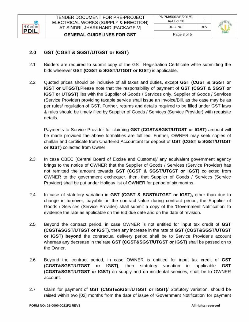
TENDER DOCUMENT FOR PRE-PROJECT
ELECTRICAL WORKS (SUPPLY & ERECTION) AT SINDRI, JHARKHAND [PACKAGE-V]
GENERAL GUIDELINES FOR GST
PNPM/5002/E/201/S-A/AT-1.20 0
DOC. NO. REV.
Page 3 of 5
FORM NO: 02-0000-0021F2 REV3 All rights reserved
2.0 GST (CGST & SGST/UTGST or IGST) 2.1 Bidders are required to submit copy of the GST Registration Certificate while submitting the
bids wherever GST (CGST & SGST/UTGST or IGST) is applicable. 2.2 Quoted prices should be inclusive of all taxes and duties, except GST (CGST & SGST or
IGST or UTGST).Please note that the responsibility of payment of GST (CGST & SGST or IGST or UTGST) lies with the Supplier of Goods / Services only. Supplier of Goods / Services (Service Provider) providing taxable service shall issue an Invoice/Bill, as the case may be as per rules/ regulation of GST. Further, returns and details required to be filled under GST laws & rules should be timely filed by Supplier of Goods / Services (Service Provider) with requisite details. Payments to Service Provider for claiming GST (CGST&SGST/UTGST or IGST) amount will be made provided the above formalities are fulfilled. Further, OWNER may seek copies of challan and certificate from Chartered Accountant for deposit of GST (CGST & SGST/UTGST or IGST) collected from Owner.
2.3 In case CBEC (Central Board of Excise and Customs)/ any equivalent government agency
brings to the notice of OWNER that the Supplier of Goods / Services (Service Provider) has not remitted the amount towards GST (CGST & SGST/UTGST or IGST) collected from OWNER to the government exchequer, then, that Supplier of Goods / Services (Service Provider) shall be put under Holiday list of OWNER for period of six months.
2.4 In case of statutory variation in GST (CGST & SGST/UTGST or IGST), other than due to
change in turnover, payable on the contract value during contract period, the Supplier of Goods / Services (Service Provider) shall submit a copy of the 'Government Notification' to evidence the rate as applicable on the Bid due date and on the date of revision.
2.5 Beyond the contract period, in case OWNER is not entitled for input tax credit of GST (CGST&SGST/UTGST or IGST), then any increase in the rate of GST (CGST&SGST/UTGST or IGST) beyond the contractual delivery period shall be to Service Provider’s account whereas any decrease in the rate GST (CGST&SGST/UTGST or IGST) shall be passed on to the Owner.
2.6 Beyond the contract period, in case OWNER is entitled for input tax credit of GST (CGST&SGST/UTGST or IGST), then statutory variation in applicable GST (CGST&SGST/UTGST or IGST) on supply and on incidental services, shall be to OWNER account.
2.7 Claim for payment of GST (CGST&SGST/UTGST or IGST)/ Statutory variation, should be raised within two [02] months from the date of issue of 'Government Notification' for payment
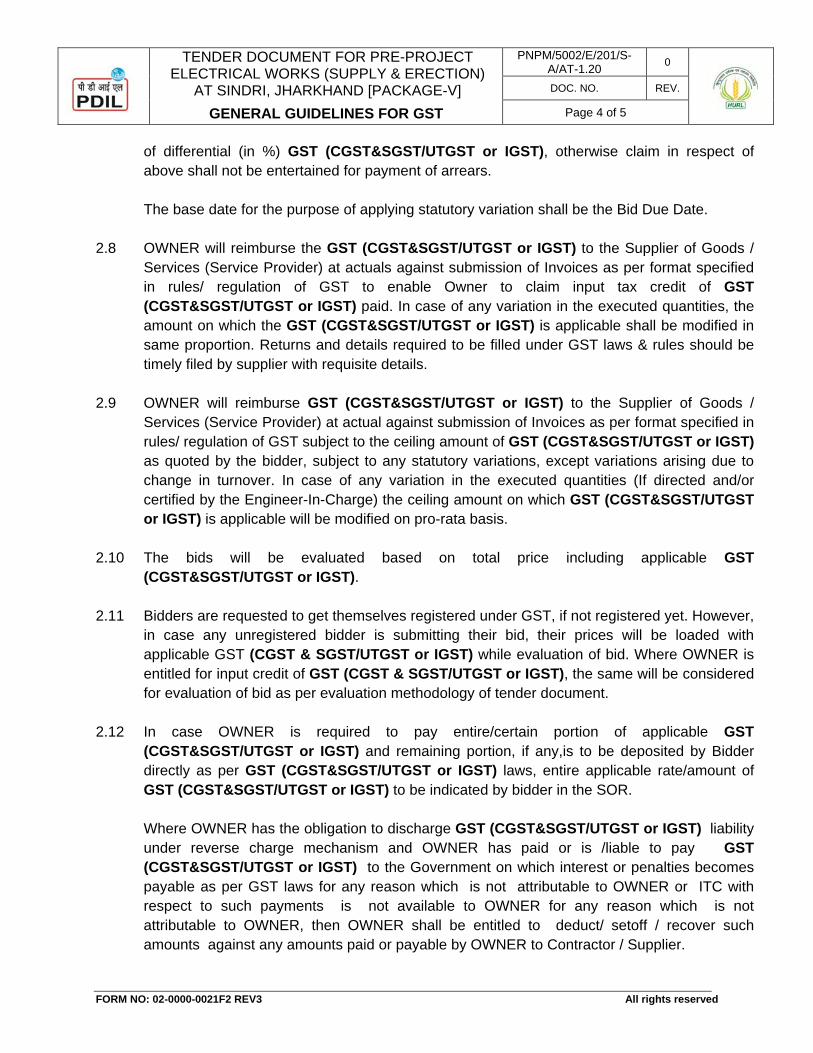
TENDER DOCUMENT FOR PRE-PROJECT
ELECTRICAL WORKS (SUPPLY & ERECTION) AT SINDRI, JHARKHAND [PACKAGE-V]
GENERAL GUIDELINES FOR GST
PNPM/5002/E/201/S-A/AT-1.20 0
DOC. NO. REV.
Page 4 of 5
FORM NO: 02-0000-0021F2 REV3 All rights reserved
of differential (in %) GST (CGST&SGST/UTGST or IGST), otherwise claim in respect of above shall not be entertained for payment of arrears. The base date for the purpose of applying statutory variation shall be the Bid Due Date.
2.8 OWNER will reimburse the GST (CGST&SGST/UTGST or IGST) to the Supplier of Goods /
Services (Service Provider) at actuals against submission of Invoices as per format specified in rules/ regulation of GST to enable Owner to claim input tax credit of GST (CGST&SGST/UTGST or IGST) paid. In case of any variation in the executed quantities, the amount on which the GST (CGST&SGST/UTGST or IGST) is applicable shall be modified in same proportion. Returns and details required to be filled under GST laws & rules should be timely filed by supplier with requisite details.
2.9 OWNER will reimburse GST (CGST&SGST/UTGST or IGST) to the Supplier of Goods /
Services (Service Provider) at actual against submission of Invoices as per format specified in rules/ regulation of GST subject to the ceiling amount of GST (CGST&SGST/UTGST or IGST) as quoted by the bidder, subject to any statutory variations, except variations arising due to change in turnover. In case of any variation in the executed quantities (If directed and/or certified by the Engineer-In-Charge) the ceiling amount on which GST (CGST&SGST/UTGST or IGST) is applicable will be modified on pro-rata basis.
2.10 The bids will be evaluated based on total price including applicable GST
(CGST&SGST/UTGST or IGST). 2.11 Bidders are requested to get themselves registered under GST, if not registered yet. However,
in case any unregistered bidder is submitting their bid, their prices will be loaded with applicable GST (CGST & SGST/UTGST or IGST) while evaluation of bid. Where OWNER is entitled for input credit of GST (CGST & SGST/UTGST or IGST), the same will be considered for evaluation of bid as per evaluation methodology of tender document.
2.12 In case OWNER is required to pay entire/certain portion of applicable GST
(CGST&SGST/UTGST or IGST) and remaining portion, if any,is to be deposited by Bidder directly as per GST (CGST&SGST/UTGST or IGST) laws, entire applicable rate/amount of GST (CGST&SGST/UTGST or IGST) to be indicated by bidder in the SOR.
Where OWNER has the obligation to discharge GST (CGST&SGST/UTGST or IGST) liability under reverse charge mechanism and OWNER has paid or is /liable to pay GST (CGST&SGST/UTGST or IGST) to the Government on which interest or penalties becomes payable as per GST laws for any reason which is not attributable to OWNER or ITC with respect to such payments is not available to OWNER for any reason which is not attributable to OWNER, then OWNER shall be entitled to deduct/ setoff / recover such amounts against any amounts paid or payable by OWNER to Contractor / Supplier.

TENDER DOCUMENT FOR PRE-PROJECT
ELECTRICAL WORKS (SUPPLY & ERECTION) AT SINDRI, JHARKHAND [PACKAGE-V]
GENERAL GUIDELINES FOR GST
PNPM/5002/E/201/S-A/AT-1.20 0
DOC. NO. REV.
Page 5 of 5
FORM NO: 02-0000-0021F2 REV3 All rights reserved
2.13 Contractor shall ensure timely submission of invoice(s) as per rules/ regulations of GST with all required supporting document(s) within a period specified in Contracts/ LOA to enable OWNER to avail input tax credit. Further, returns and details required to be filled under GST laws & rules should be timely filed by supplier with requisite details.
If input tax credit with respect to GST (CGST&SGST/UTGST or IGST) is not available to OWNER for any reason which is not attributable to OWNER, then OWNER shall not be obligated or liable to pay or reimburse GST (CGST&SGST/UTGST or IGST) charged in the invoice(s) and shall be entitled to / deduct/ setoff /recover the such GST (CGST&SGST/UTGST or IGSTUTGST) thereupon together with all penalties and interest if any, against any amounts paid or payable by OWNER to Supplier of Goods / Services.
2.14 In case the GST rating of vendor on the GST portal / Govt. official website is negative / black
listed, then the bids may be rejected by OWNER/CONSULTANT. Further, in case rating of bidder is negative / black listed after award of work for supply of goods / services, then OWNER shall not be obligated or liable to pay or reimburse GST to such vendor and shall also be entitled to deduct / recover such GST along with all penalties / interest, if any, incurred by OWNER.
TENDER DOCUMENT FOR PRE-PROJECT ELECTRICAL WORKS (SUPPLY & ERECTION)
AT SINDRI, JHARKHAND [PACKAGE-V]
FORMAT FOR FINANCIAL CAPABILITY OF THE BIDDER
PNPM/5002/E/201/S-A/AT-1.21 0
DOC. NO. REV.
Page 1 of 2
SECTION-A : COMMERCIAL
ATTACHMENT - 1.21
FORMAT FOR FINANCIAL CAPABILITY OF BIDDER

(On Chartered Accountant’s Letter Head)
FORMAT FOR CHARTERED ACCOUNTANT CERTIFICATE FOR FINANCIAL
CAPABILITY OF THE BIDDER
We have verified the Annual Accounts and other relevant records of M/s……………………………… (Name of the bidder) and certify the following A. ANNUAL TURNOVER OF LAST 3 YEARS:
Year Amount (INR) Year 1: 2016-17 Year 2: 2015-16 Year 3: 2014-15
B. FINANCIAL DATA FOR LAST AUDITED FINANCIAL YEAR :
Description FY Closing as on 31.03.2017 Amount (INR)
Current Assets Current Liabilities Working Capital (Current Assets-Current liabilities)
Net Worth (Paid up share capital and Free Reserves & Surplus)
Name of Audit Firm: [Signature of Chartered Accountant] Chartered Accountant Name: Date: Designation:
Seal: Membership no.:
Instructions: 1. The financial year would be the same as one normally followed by the bidder for its
Annual Report. 2. The bidder shall provide the audited annual financial statements duly signed &
notarized as required for this Tender document. Failure to do so would result in the Proposal being considered as non responsive.
3. For the purpose of this Tender document, (i) Annual Turnover shall be “Sale value/ Operating Income” (ii) Working Capital shall be “Current Assets less Current liabilities” and (iii) Net Worth shall be “Paid up share capital and Free Reserves & Surplus”
4. This certificate is to be submitted on the letter head of Chartered Accountant.
TENDER DOCUMENT FOR PRE-PROJECT ELECTRICAL WORKS (SUPPLY & ERECTION)
AT SINDRI, JHARKHAND [PACKAGE-V]
FORMAT FOR BIDDER NOT UNDER LIQUIDATION, COURT RECEIVERSHIP OR SIMILAR PROCEEDINGS
PNPM/5002/E/201/S-A/AT-1.22 0
DOC. NO. REV.
Page 1 of 2
SECTION-A : COMMERCIAL
ATTACHMENT - 1.22
FORMAT FOR BIDDER NOT UNDER LIQUIDATION, COURT RECEIVERSHIP OR SIMILAR PROCEEDINGS

(Self Declaration on Bidder’s Letter Head as per below performa)
DECLARATION
To , ………………………………. ………………………………. ………………………………
NIT NO. : PNPM/5002/E/201
SUBJECT : TENDER DOCUMENT FOR PRE-PROJECT ELECTRICAL WORKS (SUPPLY & ERECTION) AT SINDRI, JHARKHAND [PACKAGE-V]
Sir , We hereby declare that M/s ……………………………………. is not under liquidation, court receivership or similar proceedings as on date.
Signature Name : Designation : Seal of the Bidder.
TENDER DOCUMENT FOR PRE-PROJECT ELECTRICAL WORKS (SUPPLY & ERECTION)
AT SINDRI, JHARKHAND [PACKAGE-V]
FORMAT FOR PAST SAFETY RECORD
PNPM/5002/E/201/S-A/AT-1.23 0
DOC. NO. REV.
Page 1 of 2
SECTION-A : COMMERCIAL
ATTACHMENT - 1.23
FORMAT FOR PAST SAFETY RECORD
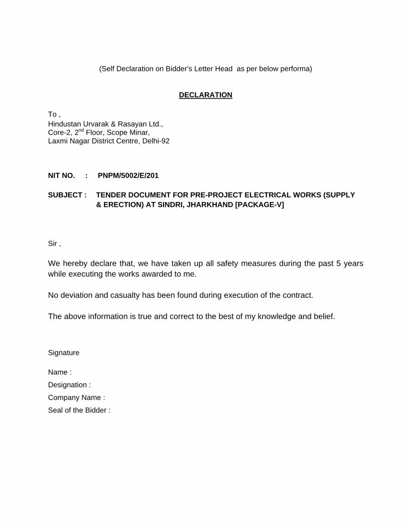
(Self Declaration on Bidder’s Letter Head as per below performa)
DECLARATION
To , Hindustan Urvarak & Rasayan Ltd., Core-2, 2nd Floor, Scope Minar, Laxmi Nagar District Centre, Delhi-92
NIT NO. : PNPM/5002/E/201
SUBJECT : TENDER DOCUMENT FOR PRE-PROJECT ELECTRICAL WORKS (SUPPLY & ERECTION) AT SINDRI, JHARKHAND [PACKAGE-V]
Sir , We hereby declare that, we have taken up all safety measures during the past 5 years while executing the works awarded to me. No deviation and casualty has been found during execution of the contract. The above information is true and correct to the best of my knowledge and belief.
Signature Name :
Designation :
Company Name :
Seal of the Bidder :

SECTION-B : TECHNICAL
PART
PART-I TECHNICAL SPECIFICATIONS FOR ELECTRICAL WORKS
PART-II TECHNICAL SPECIFICATION FOR CIVIL, STRUCTURAL & OTHER ALLIED WORKS
PART-III SCHEDULE OF RATES
PART-A : SUPPLY OF ELECTRICAL ITEMS
PART-B : ERECTION OF ELECTRICAL ITEMS
PART-C : CIVIL & STRUCTURAL WORKS
PART-D : OPERATION & MAINTENANCE
PART-IV SPECIFICATIONS FOR HEALTH, SAFETY AND ENVIRONMENT (HSE) MANAGEMENT
PROJECTS & DEVELOPMENT INDIA LTD
5002-TS-0801 4 DOCUMENT NO. REV.
SHEET 1 OF 109
4 04.01.2018 04.01.2018 REVISED AND ISSUE OF ENQUIRY KS RKV RKV 3 04.12.2017 04.12.2017 REVISED AND ISSUE OF ENQUIRY KS RKV RKV 2 07.11.2017 07.11.2017 REVISED AND ISSUE OF ENQUIRY KS RKV RKV 1 17.10.2017 17.10.2017 REVISED AND ISSUE OF ENQUIRY AP SK SK 0 10.08.2017 10.08.2017 FOR ISSUE OF ENQUIRY AP/KS SK SK
REV. REV. DATE EFF. DATE PURPOSE PREPD. REVWD. APPD. FORM NO: 02-0000-0021F1 REV4 All rights reserved
TECHNICAL SPECIFICATION
FOR
PRE-PROJECT ELECTRICAL WORKS
(SUPPLY, ERECTION, TESTING, COMMISSIONING, OPERATION & MAINTENANCE OF CONSTRUCTION POWER
AND ELECTRICAL FACILITIES)
AT
HURL, SINDRI
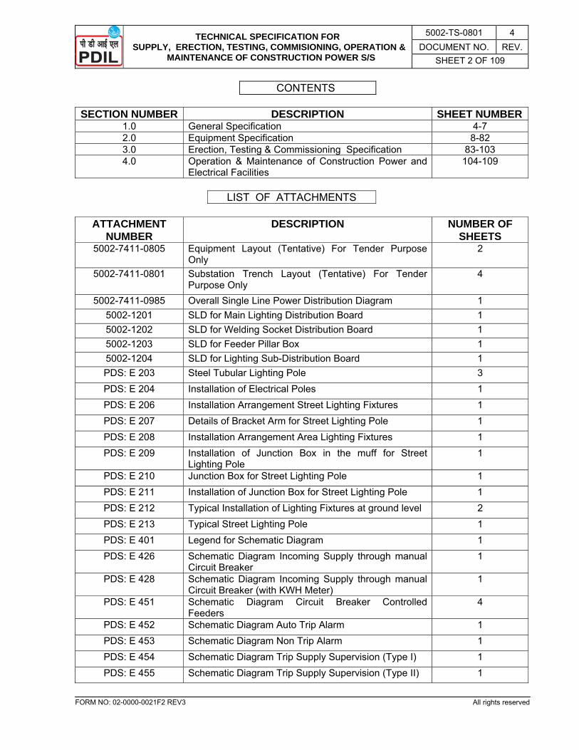
TECHNICAL SPECIFICATION FOR SUPPLY, ERECTION, TESTING, COMMISIONING, OPERATION &
MAINTENANCE OF CONSTRUCTION POWER S/S
5002-TS-0801 4 DOCUMENT NO. REV.
SHEET 2 OF 109
FORM NO: 02-0000-0021F2 REV3 All rights reserved
CONTENTS
SECTION NUMBER DESCRIPTION SHEET NUMBER1.0 General Specification 4-7 2.0 Equipment Specification 8-82 3.0 Erection, Testing & Commissioning Specification 83-103 4.0 Operation & Maintenance of Construction Power and
Electrical Facilities 104-109
LIST OF ATTACHMENTS
ATTACHMENT
NUMBER DESCRIPTION NUMBER OF
SHEETS 5002-7411-0805 Equipment Layout (Tentative) For Tender Purpose
Only 2
5002-7411-0801 Substation Trench Layout (Tentative) For Tender Purpose Only
4
5002-7411-0985 Overall Single Line Power Distribution Diagram 1 5002-1201 SLD for Main Lighting Distribution Board 1 5002-1202 SLD for Welding Socket Distribution Board 1 5002-1203 SLD for Feeder Pillar Box 1 5002-1204 SLD for Lighting Sub-Distribution Board 1 PDS: E 203 Steel Tubular Lighting Pole 3 PDS: E 204 Installation of Electrical Poles 1 PDS: E 206 Installation Arrangement Street Lighting Fixtures 1 PDS: E 207 Details of Bracket Arm for Street Lighting Pole 1 PDS: E 208 Installation Arrangement Area Lighting Fixtures 1 PDS: E 209 Installation of Junction Box in the muff for Street
Lighting Pole 1
PDS: E 210 Junction Box for Street Lighting Pole 1 PDS: E 211 Installation of Junction Box for Street Lighting Pole 1 PDS: E 212 Typical Installation of Lighting Fixtures at ground level 2 PDS: E 213 Typical Street Lighting Pole 1 PDS: E 401 Legend for Schematic Diagram 1 PDS: E 426 Schematic Diagram Incoming Supply through manual
Circuit Breaker 1
PDS: E 428 Schematic Diagram Incoming Supply through manual Circuit Breaker (with KWH Meter)
1
PDS: E 451 Schematic Diagram Circuit Breaker Controlled Feeders
4
PDS: E 452 Schematic Diagram Auto Trip Alarm 1 PDS: E 453 Schematic Diagram Non Trip Alarm 1 PDS: E 454 Schematic Diagram Trip Supply Supervision (Type I) 1 PDS: E 455 Schematic Diagram Trip Supply Supervision (Type II) 1
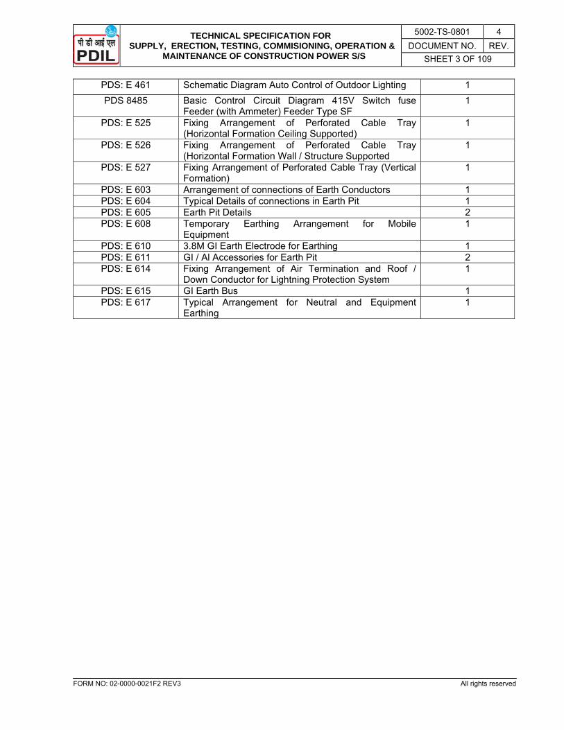
TECHNICAL SPECIFICATION FOR SUPPLY, ERECTION, TESTING, COMMISIONING, OPERATION &
MAINTENANCE OF CONSTRUCTION POWER S/S
5002-TS-0801 4 DOCUMENT NO. REV.
SHEET 3 OF 109
FORM NO: 02-0000-0021F2 REV3 All rights reserved
PDS: E 461 Schematic Diagram Auto Control of Outdoor Lighting 1 PDS 8485 Basic Control Circuit Diagram 415V Switch fuse
Feeder (with Ammeter) Feeder Type SF 1
PDS: E 525 Fixing Arrangement of Perforated Cable Tray (Horizontal Formation Ceiling Supported)
1
PDS: E 526 Fixing Arrangement of Perforated Cable Tray (Horizontal Formation Wall / Structure Supported
1
PDS: E 527 Fixing Arrangement of Perforated Cable Tray (Vertical Formation)
1
PDS: E 603 Arrangement of connections of Earth Conductors 1 PDS: E 604 Typical Details of connections in Earth Pit 1 PDS: E 605 Earth Pit Details 2 PDS: E 608 Temporary Earthing Arrangement for Mobile
Equipment 1
PDS: E 610 3.8M GI Earth Electrode for Earthing 1 PDS: E 611 GI / Al Accessories for Earth Pit 2 PDS: E 614 Fixing Arrangement of Air Termination and Roof /
Down Conductor for Lightning Protection System 1
PDS: E 615 GI Earth Bus 1 PDS: E 617 Typical Arrangement for Neutral and Equipment
Earthing 1
TECHNICAL SPECIFICATION FOR SUPPLY, ERECTION, TESTING, COMMISIONING, OPERATION &
MAINTENANCE OF CONSTRUCTION POWER S/S
5002-TS-0801 4 DOCUMENT NO. REV.
SHEET 4 OF 109
FORM NO: 02-0000-0021F2 REV3 All rights reserved
SECTION – 1.0
GENERAL SPECIFICATION
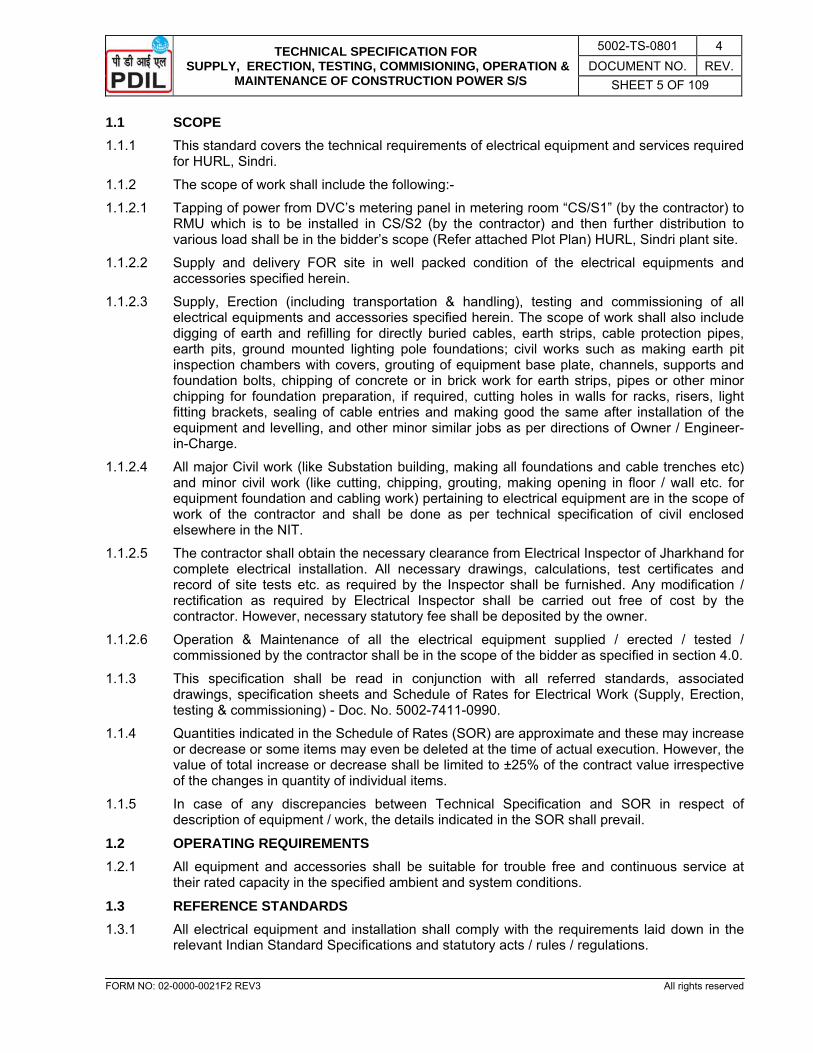
TECHNICAL SPECIFICATION FOR SUPPLY, ERECTION, TESTING, COMMISIONING, OPERATION &
MAINTENANCE OF CONSTRUCTION POWER S/S
5002-TS-0801 4 DOCUMENT NO. REV.
SHEET 5 OF 109
FORM NO: 02-0000-0021F2 REV3 All rights reserved
1.1 SCOPE 1.1.1 This standard covers the technical requirements of electrical equipment and services required
for HURL, Sindri.
1.1.2 The scope of work shall include the following:-
1.1.2.1 Tapping of power from DVC’s metering panel in metering room “CS/S1” (by the contractor) to RMU which is to be installed in CS/S2 (by the contractor) and then further distribution to various load shall be in the bidder’s scope (Refer attached Plot Plan) HURL, Sindri plant site.
1.1.2.2 Supply and delivery FOR site in well packed condition of the electrical equipments and accessories specified herein.
1.1.2.3 Supply, Erection (including transportation & handling), testing and commissioning of all electrical equipments and accessories specified herein. The scope of work shall also include digging of earth and refilling for directly buried cables, earth strips, cable protection pipes, earth pits, ground mounted lighting pole foundations; civil works such as making earth pit inspection chambers with covers, grouting of equipment base plate, channels, supports and foundation bolts, chipping of concrete or in brick work for earth strips, pipes or other minor chipping for foundation preparation, if required, cutting holes in walls for racks, risers, light fitting brackets, sealing of cable entries and making good the same after installation of the equipment and levelling, and other minor similar jobs as per directions of Owner / Engineer-in-Charge.
1.1.2.4 All major Civil work (like Substation building, making all foundations and cable trenches etc) and minor civil work (like cutting, chipping, grouting, making opening in floor / wall etc. for equipment foundation and cabling work) pertaining to electrical equipment are in the scope of work of the contractor and shall be done as per technical specification of civil enclosed elsewhere in the NIT.
1.1.2.5 The contractor shall obtain the necessary clearance from Electrical Inspector of Jharkhand for complete electrical installation. All necessary drawings, calculations, test certificates and record of site tests etc. as required by the Inspector shall be furnished. Any modification / rectification as required by Electrical Inspector shall be carried out free of cost by the contractor. However, necessary statutory fee shall be deposited by the owner.
1.1.2.6 Operation & Maintenance of all the electrical equipment supplied / erected / tested / commissioned by the contractor shall be in the scope of the bidder as specified in section 4.0.
1.1.3 This specification shall be read in conjunction with all referred standards, associated drawings, specification sheets and Schedule of Rates for Electrical Work (Supply, Erection, testing & commissioning) - Doc. No. 5002-7411-0990.
1.1.4 Quantities indicated in the Schedule of Rates (SOR) are approximate and these may increase or decrease or some items may even be deleted at the time of actual execution. However, the value of total increase or decrease shall be limited to ±25% of the contract value irrespective of the changes in quantity of individual items.
1.1.5 In case of any discrepancies between Technical Specification and SOR in respect of description of equipment / work, the details indicated in the SOR shall prevail.
1.2 OPERATING REQUIREMENTS 1.2.1 All equipment and accessories shall be suitable for trouble free and continuous service at
their rated capacity in the specified ambient and system conditions.
1.3 REFERENCE STANDARDS
1.3.1 All electrical equipment and installation shall comply with the requirements laid down in the relevant Indian Standard Specifications and statutory acts / rules / regulations.

TECHNICAL SPECIFICATION FOR SUPPLY, ERECTION, TESTING, COMMISIONING, OPERATION &
MAINTENANCE OF CONSTRUCTION POWER S/S
5002-TS-0801 4 DOCUMENT NO. REV.
SHEET 6 OF 109
FORM NO: 02-0000-0021F2 REV3 All rights reserved
1.4 TESTS & INSPECTION 1.4.1 All equipment shall be tested in accordance to relevant standards in presence of owner’s
representative at manufacturer's works before despatch / at site before installation. All such tests shall be arranged by the contractor and testing charges, if any, shall be borne by the contractor.
1.4.2 Electrical installation work shall be subjected to inspection by owner / his authorised representative, statutory bodies like Electrical Inspector, Factory Inspector and where applicable by equipment supplier’s engineer. The contractor shall carry out without extra cost to owner rectifications / modifications desired by the above authorities to make the installation conforming to I.E. Rules etc.
1.4.3 The owner may reject any portion of the work considered defective or of poor workmanship and the contractor shall make good these defects without extra cost to owner.
1.5 ERECTION, TESTING & COMMISSIONING 1.5.1 The contractor shall undertake erection of all equipment in accordance with good engineering
practices in conformity with statutory regulations and Code of Practice and to the entire satisfaction of the owner.
1.5.2 Indicative erection drawings shall be supplied by consultant / owner to the successful bidder. Contractor shall make required changes as per the vendor drawing details and as per site requirement. Contractor shall also supply as built drawings for complete installation.
1.5.3 The contractor shall arrange all the necessary erection tools, tackles, testing and measuring instruments and shall supply erection materials and consumables.
1.5.4 The contractor shall be deployed competent testing contractor at site for testing and commissioning of the electrical system.
1.5.5 The contractor shall clear the site after commissioning of the equipments / system and obtain the Site Clearance Certificate from owner’s Engineer-in-charge.
1.6 DRAWINGS AND DOCUMENTS 1.6.1 The bidder shall supply the drawings and documents as per list of Documents under Section
2.0.
1.6.2 The Contractor shall be responsible for preparation and submission of four sets of drawings for approval.
1.7 CO-ORDINATION WITH OTHERS 1.7.1 The contractor shall co-ordinate with owner's other contractors / agencies as required.
1.7.2 All liasioning with CEA for getting charging approval shall be in the scope of the contractor.
1.8 SPARE PARTS 1.8.1 The contractor shall quote for the recommended spare parts required for initial 2 years of
operation for all equipment supplied by them.
1.8.2 Commissioning spares as required shall be supplied without any extra cost to the owner.
1.9 TOOLS 1.9.1 The contractor shall supply at least one set of all special tools required for maintenance of the
equipment supplied by them.
1.10 SCHEDULE 1.10.1 Bidder shall furnish bar chart for complete scope of their works.
TECHNICAL SPECIFICATION FOR SUPPLY, ERECTION, TESTING, COMMISIONING, OPERATION &
MAINTENANCE OF CONSTRUCTION POWER S/S
5002-TS-0801 4 DOCUMENT NO. REV.
SHEET 7 OF 109
FORM NO: 02-0000-0021F2 REV3 All rights reserved
1.11 DEVIATIONS 1.11.1 Clause-wise deviations, if any, from this specification shall be clearly indicated in the offer
with reasoning.
TECHNICAL SPECIFICATION FOR SUPPLY, ERECTION, TESTING, COMMISIONING, OPERATION &
MAINTENANCE OF CONSTRUCTION POWER S/S
5002-TS-0801 4 DOCUMENT NO. REV.
SHEET 8 OF 109
FORM NO: 02-0000-0021F2 REV3 All rights reserved
SECTION – 2.0
EQUIPMENT SPECIFICATION

TECHNICAL SPECIFICATION FOR SUPPLY, ERECTION, TESTING, COMMISIONING, OPERATION &
MAINTENANCE OF CONSTRUCTION POWER S/S
5002-TS-0801 4 DOCUMENT NO. REV.
SHEET 9 OF 109
FORM NO: 02-0000-0021F2 REV3 All rights reserved
2.1 GENERAL 2.1.1 Equipment to be supplied by the contractor shall conform to relevant Indian Standards,
Engineering Standards, Specification Sheets & Drawings enclosed.
2.1.2 Equipment shall also comply with the requirement of Statutory Acts, Rules & Regulations.
2.1.3 All equipments shall be suitable for operation in following systems, ambient conditions & area classification:-
2.1.3.1 System Details
33KV ± 10%, 3 Ph., 50 Hz 3.3KV ± 10%, 3 Ph., 50 Hz 415V ±10%, 3 Ph. & N, 50 Hz 240V ±10%, 1 Ph, 50 Hz
2.1.3.2 Fault Level
33KV : 1200 MVA
3.3KV : 150 MVA
415V : 36 MVA
2.1.3.3 Ambient Conditions
Temp. Max./Min./Design Ref. : 47.7° / 2.3° / 50° C Relative Humidity : 100% (Max.) Alt. above MSL : < 1000 m Atmospheric pollution : Ammonia Vapour & Urea Dust.
2.1.3.4 Area Classification
Area : Hazardous Classification : Zone-2 Temp. Class : T3 Gas group : IIC
2.1.4 Make of the equipment / components shall be as specified elsewhere in this specification. Make of the equipment / components not indicated shall be subject to owner’s approval.
2.1.5 Drawings & Documents for various equipments as indicated in respective Engineering Standards shall be furnished. For other equipments, GA drawings & descriptive catalogues shall be furnished. For flameproof / increased safety equipment, manufacturer's type test certificates from CIMFR (earlier CMRI), Dhanbad for the quoted items shall be furnished along with the bid. All flameproof equipment must have approval of PESO (earlier CCOE), Nagpur.
2.2 EQUIPMENTS 2.2.1 33KV SF6 INSULATED RING MAIN UNIT 2.2.1.1 SF6 insulated 33KV, 630A, metal enclosed Ring Main Unit shall be suitable for operating at the
specified rating continuously, with the specified voltage and frequency variations under the ambient conditions, without exceeding the permissible temperature rise and without any detrimental effect on any part. RMU shall also conform to the specification sheet (attached in this specification) and Feeder Details (attached in this specification).
2.2.1.2 33KV RMU conforms to IEC 62271-200 & 100 (for switchgear and VCB), IEC 60265-1 (for General Purpose switches), IEC 62271-102 (for Disconnectors and Earthing switches) and IEC 60694 (for Common clauses).

TECHNICAL SPECIFICATION FOR SUPPLY, ERECTION, TESTING, COMMISIONING, OPERATION &
MAINTENANCE OF CONSTRUCTION POWER S/S
5002-TS-0801 4 DOCUMENT NO. REV.
SHEET 10 OF 109
FORM NO: 02-0000-0021F2 REV3 All rights reserved
2.2.1.3 The Ring Main Unit shall be suitable for outdoor installation, and have the configuration as below: one no. 630 A VCB as incoming, three nos. 630 A VCB as outgoing, CT and PT for metering and protection, Trivector meter/Energy Meter as recommended by local electricity board, protective relays (microprocessor based numerical relays) etc.
2.2.1.4 The outgoing transformer protection (33/3.45KV, 3.0 MVA Transformer) unit consists of VCB and an earthing switch equal to those present in the line unit.
2.2.1.5 Incoming and outgoing cable sizes shall be as indicated in the SLD and Specification Sheet and Feeder Details.
2.2.1.6 Suitable arrangement for DC power for the RMU is to be provided by the vendor. Spare power pack with inside and outside isolation shall be provided. DC Voltage shall be 220V DC. Power pack shall have the battery back-up of 6 hours.
2.2.1.7 Following safety devices to be provided: Controls and Fuse protection box to protect the operator from the moving parts and from the auxiliary voltages present inside.
Pressure relief valves which assure the gas flow-off in case of a possible internal arc, without causing breaks on the front part.
Key lock shall be provided for preventing wrong operation.
Door interlock device, allowing to open the switchgear protective boxes only when the earthing switch is positioned on “closed earth”
Interlock on the fuse-holder cover, preventing to place the cover itself on the fuse-holder when the fuse is not mounted inside it, so preventing to put into service.
Device on the fuse compartment door, signaling the fuse blown condition through a coloured indicator and preventing the door itself to get closed whwn it was opened by blown fuse.
2.2.1.8 Following interlocks to be provided: Interlock between VCB and earthing switch. Interlock between VCB of the transformer protection unit and fuse compartment door.
2.2.1.9 All protective relays shall be microprocessor based / numerical relays. 2.2.1.10 RMU shall be mechanically operated device with VCB ON/OFF via handle.
2.2.1.11 RMU shall be suitable for Internal Arc Classification (IAC AFL) withstand current of 20kA for 1 sec.
2.2.1.12 RMU major live-parts like busbars, jumpers, VCBs and Isolators enclosed in an IP67 (partial submersion proof) tank made by robotically welding non-magnetic and non-ferritic stainless steel sheet with high-quality corrosion-proof performance (AIS Grade 304).Further, the complete enclosure shall be filled with SF6 gas at above atmospheric pressure to increase compactness, improve clearances and prevent live-conductor from coming in contact with external environmental deterrents like dust, moisture, pollution etc. The gas shall be monitored via temperature compensated monitor provided on front facia, and shall be refillable at site.
2.2.1.13 3 Years of warranty to be provide for the offered RMU. 2.2.1.14 Bidder to recommend required no. of spares for 3 years of operation and maintenance with unit
price of each spare. 2.2.1.15 Metering CT & PT in all the feeders shall be of Accuracy class 0.2
TECHNICAL SPECIFICATION FOR SUPPLY, ERECTION, TESTING, COMMISIONING, OPERATION &
MAINTENANCE OF CONSTRUCTION POWER S/S
5002-TS-0801 4 DOCUMENT NO. REV.
SHEET 11 OF 109
FORM NO: 02-0000-0021F2 REV3 All rights reserved
2.2.2 POWER TRANSFORMER 2.2.2.1 The transformers shall be double wound, copper conductor, Dyn11 type. Transformers shall
have 33 KV and 3.3 KV primary windings. Transformers shall also conform to the specification sheet (attached in this specification). Transformers rated up to 2500KVA shall have energy efficiency of Level 3.
2.2.2.2 The transformer shall be suitable for operating at the rated capacity continuously at any of the taps, under the ambient conditions and with the voltage and frequency variations indicated in Specification Sheet without exceeding the permissible temperature rise and without any detrimental effect on any part.
2.2.2.3 The transformer shall also be capable of delivering rated current at a voltage equal to 105 % of the rated voltage.
2.2.2.4 The transformers shall have ‘OFF’ load tap changers. 2.2.2.5 The off-circuit tap changing shall be affected by an externally operated handle capable of being
padlocked in any position and provided with tap position indicator and mechanical stops at the extreme positions.
2.2.2.6 The temperature rise of the winding, oil and core shall not exceed the values specified in IS: 2026 when the transformer is delivering its rated output continuously under the service conditions as indicated in Specification Sheet.
2.2.2.7 The HV and LV side terminal arrangement shall be provided as specified in Specification Sheet. Disconnecting link chambers shall be provided on the transformer primary side in all cases as well as on secondary side, except where the termination is through bus duct. The disconnecting chambers shall be oil filled, preferably connected with the main tank through an isolating valve and also provided with a drain valve. However for system not exceeding 33 KV, air filled disconnecting chamber may be accepted. Suitable cable end box complete with cable glands and lugs shall be provided for termination of cables as indicated in Specification Sheet. Gland plate for single core cables shall be non-magnetic.
2.2.2.8 The transformer shall be able to withstand the electro-dynamic and thermal stresses due to terminal short circuit of the secondary, assuming the primary side fed from an infinite bus. All leads and windings in cores shall be properly supported, clamped and tightened after vacuum drying to ensure the short circuit withstand capacity. The short circuit withstand duration shall be 3 Secs.
2.2.2.9 The transformer shall be so designed as to minimise any undue noise and vibration. 2.2.2.10 Due attention shall be given in the design for the suppression of harmonics. 2.2.2.11 The transformer core shall be of high grade, non-ageing, electrical silicon cold rolled magnetic
sheet steel of low hysterisis loss and high permeability. The maximum flux density in any part of the core and yoke at rated voltage and frequency shall not exceed 1.7 Tesla. The core structure shall be securely grounded to prevent electrostatic potential. Lifting eyes and lugs shall be provided on the limbs and coils assembly. Preferably no bolt shall be used in the cores. Clamping shall be done external to the limb. Bolts passing through the yoke, if any, shall be insulated for 2 KV for transformers rated up to 33 KV and 5 KV for higher voltage ratings.
2.2.2.12 The temperature of the core shall not exceed that permitted in IS. 2.2.2.13 The tank shall preferably be made of mild steel plate of adequate thickness capable of
withstanding stress not less than 0.40 kg/cm2, properly welded and gusseted to ensure a rigid construction. It shall also be able to withstand normal transportation shocks without any deformation and shall be capable of withstanding following vacuum.

TECHNICAL SPECIFICATION FOR SUPPLY, ERECTION, TESTING, COMMISIONING, OPERATION &
MAINTENANCE OF CONSTRUCTION POWER S/S
5002-TS-0801 4 DOCUMENT NO. REV.
SHEET 12 OF 109
FORM NO: 02-0000-0021F2 REV3 All rights reserved
Highest System Voltage MVA Rating Vacuum in mm of Hg
Up to 72 KV Up to 1.6 250
Above 1.6 to 20 500
Above 20 760
Above 72 KV For all Ratings 760
2.2.2.14 For outdoor transformer, the top of the tank, the marshalling box and the headers of radiators, shall be of such a construction so as to prevent accumulation of water.
2.2.2.15 Radiators, where necessary, shall be provided on the tank to facilitate cooling. These shall be detachable type and shall be provided with isolating valves at ends, drain plug and air release plug. The radiators shall be fabricated out of minimum 1.25 mm thick seamless steel tubing or pressed sheet steel. For sizes up to 500 KVA, cooling tubes shall be acceptable.
2.2.2.16 Fittings such as conservator and associated pipes, explosion vent pipe etc. shall be designed to withstand vacuum as specified in Clause 2.2.2.13 against atmospheric pressure.
2.2.2.17 Fittings such as rating plate, dehydrating breather, off-circuit tapping switch, dial type thermometer etc. which need to be observed/ operated, shall be mounted at convenient heights of not more than 1.5 M from the base of the transformer and located so as to be clearly visible from the front.
2.2.2.18 All opening shall be provided with gasketted metallic covers for protection during transportation. 2.2.2.19 All valves shall be of globe/butterfly type provided with blanking plates. The valve body shall be
made of either Carbon Steel with trim of 13 Cr. steel or gun metal. 2.2.2.20 The rating plate, the terminal diagram and terminal marking plates shall be made of Aluminium
and shall contain relevant details as per IS: 2026. The Code No. of equipment shall be marked on a separate plate.
2.2.2.21 All terminals shall be anti loosening type and complete with connectors of required size. The earthing terminals shall have identification marks.
2.2.2.22 The marshalling box shall be dust, weather and vermin proof type made of sheet steel of not less than 2 mm thick. The box shall be rectangular in shape having sufficient space for easy termination of cables. The terminal block shall be pressure clamp type. 10% spare terminals shall be provided.
2.2.2.23 Suitable heavy duty double compression type rolled Aluminium cable glands for all incoming and outgoing cables shall be provided.
2.2.2.24 The current transformers, if specified in Specification Sheet, shall be provided and shall comply with IS: 2705. The C.T. terminals shall be accessible through a weatherproof removable cover for the purpose of testing etc. CT polarity shall be clearly marked. The C.T. for standby earth fault protection shall be 15 VA, 5P10. The C.T’s for differential and restricted earth fault protection shall be of Class PS accuracy. The values of Vk and Imag for these CTs shall be furnished.
2.2.2.25 Make of the all bought out items such as Buchholz relay, Oil Temperature Indicator, Winding Temperature Indicator, Magnetic Oil Level Gauge, Bushings etc. shall be indicated by the bidder and shall be subject to the owner / consultant for approval.
2.2.2.26 Current rating of bushings shall be at least 1.5 times the full load current subject to a minimum of 400A.
2.2.2.27 Neutral bushing shall be of same voltage grade as that of phase. 2.2.2.28 Bushing and support insulators shall be suitable for highly polluted area with creepage distance
of 31mm / kV.
TECHNICAL SPECIFICATION FOR SUPPLY, ERECTION, TESTING, COMMISIONING, OPERATION &
MAINTENANCE OF CONSTRUCTION POWER S/S
5002-TS-0801 4 DOCUMENT NO. REV.
SHEET 13 OF 109
FORM NO: 02-0000-0021F2 REV3 All rights reserved
2.2.2.29 Fittings and additional fittings as mentioned in Engineering Standard (ES: 8043) and Specification Sheet shall be provided.
2.2.2.30 Transformer cable boxes shall be dust, vermin and weather proof type with IP-55 degree of protection.
2.2.2.31 HV & LV Cable Terminal Box enclosure shall have provision for Earthing at two distinct points. 2.2.2.32 All gaskets joints for transformer body Earthing shall be provided with continuity conductor (GI /
Al strip) to electrically connect the transformer body. 2.2.2.33 Top & Bottom Oil sampling valve shall be provided in each transformer. 2.2.2.34 Oil level Glass gauge shall be provided on conservator. 2.2.2.35 Bus Bar (if used) shall be of tinned copper. 2.2.2.36 Magnetic Oil Level Gauge with alarm and trip contacts shall be provided in each transformer. 2.2.2.37 Radiator Vacuum withstand capacity shall be designed as per Cl. No.6.2.1 of Doc No. ES:
8043. 2.2.2.38 The marshalling box shall also consist of following:
a) 240V AC Space heater with thermostat.
b) Door switch operated lighting fixture suitable for 240V AC.
c) The box shall have a lockable door.
d) The complete drawing of the marshalling box wiring diagram shall be provided inside the marshalling box on SS plate.
e) Isolation switch for 240V, 50Hz shall be provided in the marshalling box.
f) Two nos. Earthing terminals.
g) Degree of protection – IP55.
h) Door shall be with lift-off type hinges
2.2.2.39 Main transformer, conservator, piping, radiators, marshalling box, cable boxes, supports etc. shall have uniform shade of painting.
2.2.2.40 Arrangement of marshalling box shall be such that its front face is always being visible from front side.
2.2.2.41 Analog OTI / WTI against dial type for all transformers (with RS 485) shall be provided.
2.2.2.42 Bidder to provide CT for WTI which shall be installed in tank.
2.2.2.43 Stand-by Earth Fault CT 5P10 for all transformers shall be provided in transformer neutral by the bidder.
2.2.2.44 Mounting provision for REF CT for all transformers shall be provided in transformer neutral by the bidder.
2.2.2.45 PRV with alarm and trip contacts shall be required for 4 MVA transformers whereas Equalizer pipe and double explosion vent diaphragm shall be provided for 2 MVA transformers.
2.2.2.46 Cable box / tank top cover shall be provided with slope / canopy. Cable box shall be suitable for termination of XLPE insulated cable through heat shrinkable Raychem kit.
2.2.2.47 High grade Cold Roll Grain Oriented sheet steel shall be used for transformer core.
2.2.2.48 Proper supporting arrangement shall be provided for LV & HV cable terminal box.
2.2.2.49 Aluminium foil wound transformer shall not be acceptable.
TECHNICAL SPECIFICATION FOR SUPPLY, ERECTION, TESTING, COMMISIONING, OPERATION &
MAINTENANCE OF CONSTRUCTION POWER S/S
5002-TS-0801 4 DOCUMENT NO. REV.
SHEET 14 OF 109
FORM NO: 02-0000-0021F2 REV3 All rights reserved
2.2.3 SWITCHBOARDS 2.2.3.1 The switchboards shall consist of an assembly of a series of floor mounting, identical, metal
clad, cubicle type panels placed side by side to form a compact assembly and shall be extensible on either side.
2.2.3.2 The complete assembly shall be dust, dam and vermin proof having minimum degree of protection IP 4X for HV switchboards and IP-52 for LV switchboards up to 1600A rating and IP-4X for LV switchboards above 1600A rating.
2.2.3.3 The bus-bars shall be amply sized to carry the rated continuous current under the specified ambient temperature without exceeding the limits specified in IS: 8084. The thermal rating of the bus-bars shall be designed to withstand the system fault current for 3 seconds for HV Switchboard and for 1 second for LV Switchboard without exceeding the limiting temperature. Calculation for bus-bar sizing shall be furnished along with the offer.
2.2.3.4 Horizontal bus-bars shall run in a separate compartment through the entire length of the board and shall be of same cross-section throughout. Stepped bus-bars shall not be acceptable.
2.2.3.5 The bus-bars shall be rigidly supported at equal intervals to withstand the stresses due to full short circuit and also to take care of thermal expansion.
2.2.3.6 All external hardwares shall be cadmium plated. The hardwares for fixing the removable parts shall be provided with retaining devices.
2.2.3.7 The doors and the removable covers shall be provided with non-deteriorating neoprene gaskets. Gaskets without any discontinuity shall be preferred. Gaskets shall be held in position in groove, in shaped sheet steel work or these shall be of U type.
2.2.3.8 All the components shall be accessible for inspection and maintenance without the necessity of removing the adjacent ones. Their mounting shall be accessible and ensure the necessary degree of safety.
2.2.3.9 C.T.s shall be class F insulated and vacuum impregnated or resin cast type and shall conform to IS: 2705. The C.T.s shall be rigidly mounted and shall be easily accessible for maintenance and testing.
2.2.3.10 The C.T.s output shall be minimum 15 VA per phase and in any case, the output shall be adequate for the protection and metering duties involved with sufficient margin. The C.T.s shall have the following accuracies for the various applications:
Application Class of Accuracy as per IS: 2705
i) For metering service 1 ii) For use with protective relays 5 P iii) For use with restricted earth fault PS
and differential relays
2.2.3.11 The C.T. cores for metering and protection shall be separate.
2.2.3.12 The V.T.s shall be class F insulated and vacuum impregnated or resin cast type conforming to IS: 3156
2.2.3.13 The rated output of each VT shall be adequate for the relays, meters and associated wiring connected to it with sufficient margin and shall not be less than 200 VA per phase for HV Switchboard and 50VA per phase for LV Switchboard.
2.2.3.14 The accuracy class of V.T.s shall be 1 as per IS: 3156.
2.2.3.15 Mounting height of components requiring operations and observation shall not be lower than 300 mm and higher than 1800 mm.
TECHNICAL SPECIFICATION FOR SUPPLY, ERECTION, TESTING, COMMISIONING, OPERATION &
MAINTENANCE OF CONSTRUCTION POWER S/S
5002-TS-0801 4 DOCUMENT NO. REV.
SHEET 15 OF 109
FORM NO: 02-0000-0021F2 REV3 All rights reserved
2.2.3.16 All live parts which are accessible after opening of front and back door/cover shall be properly insulated or provided with insulating barrier to prevent accidental contact. Phase insulating barriers shall be provided between the breaker poles. Removal facility shall be provided for all such barriers.
2.2.3.17 Switchboard shall be provided with following inter locks and safety features:
i) It shall not be possible to open the compartment door unless the breaker is drawn to isolated position.
ii) The withdrawn and engagement of a circuit breaker shall not be possible unless it is in open position.
iii) The operation of a circuit breaker shall not be possible unless it is in fully service, test or isolated position.
iv) It shall not be possible to close the circuit breaker in service position unless all auxiliary and control circuits are connected.
v) A breaker of the lower rating shall be prevented from engaging with the stationary element of higher rating.
vi) Insertion of the manual mechanism shall render the motorised mechanism in operation. vii) Circuit breaker ‘ON’, ‘OFF’ indication shall be provided at the back of each panel. Alternatively,
alarm shall be provided in case panel back door is opened with breaker “ON”. viii) Caution nameplate shall be provided at the back of incomer’s panels where terminals are likely
to remain live and isolation is possible only from remote end. 2.2.3.18 The wiring shall be carried out with flexible stranded PVC insulated copper conductor cables of
1100 Volt grade. The minimum size of wires shall be as follows:
C.T. Circuit -- 2.5 Sq. mm V.T. and Control Circuits -- 1.5 Sq. mm
2.2.3.19 Suitable arrangement for DC and auxiliary AC power for each switchboard is to be provided by the vendor. Spare power pack with inside and outside isolation shall be provided. DC Voltage shall be 220V DC and AC Auxiliary Voltage shall be 240V AC. Power pack shall have the battery back-up of 6 hours.
2.2.3.20 Automatic safety shutter, with Padlocking facility for locking in closed position, to completely cover the spouts for the bus-bars and cable connection when the breaker is withdrawn.
2.2.3.21 LOTO locking system to be provided for safety purpose while taking clearance for maintenance work. For this necessary Hasps and locks shall be provided in the switchboards.
2.2.3.22 Test push buttons shall be provided for checking the healthiness of control circuit interlock in all feeders.
2.2.3.23 Push buttons for checking the healthiness of indication lamps in all feeders shall be provided.
2.2.3.24 Auxiliary AC power is to be tapped from the feeder itself.
2.2.3.25 Name plate shall be of Aluminium / black Perspex with white engraving and of minimum 3 mm thick.
2.2.3.26 Vendor to submit the schematic diagram for all the switchboards along with the bid and for owner/consultant approval before commencement of manufacturing.
A. HV SWITCHBOARDS
2.2.3.27 HV switchboard conforms to IEC 62271-200 (for switchgear), IEC62271-100 (for VCB) and IEC 60694 (for common clause).
2.2.3.28 HV Switchboard shall be manufactured and supplied by the OEM of the Circuit Breaker. Design & manufacturing of HV switchboard by channel partner, franchise or sub-vendor of the OEM shall not be acceptable in any case.
TECHNICAL SPECIFICATION FOR SUPPLY, ERECTION, TESTING, COMMISIONING, OPERATION &
MAINTENANCE OF CONSTRUCTION POWER S/S
5002-TS-0801 4 DOCUMENT NO. REV.
SHEET 16 OF 109
FORM NO: 02-0000-0021F2 REV3 All rights reserved
2.2.3.29 The HV switchboard shall be indoor, metal enclosed, drawout type, equipped with Vacuum Circuit Breakers (VCB) for all feeders. 3.3KV Switchboard shall also conform to the specification sheet (attached in this specification) and Feeder Details (attached in this specification).
2.2.3.30 The circuit breakers shall be of the 3 phase, single break, single level, horizontal draw-out, horizontal isolation type. The medium of arc quenching shall be vacuum.
2.2.3.31 The framework of the cubicles shall be bolted / welded construction. The minimum thickness of sheet steel shall be 3 mm for base channel and 2 mm for other members. The doors and covers shall be fabricated from cold rolled sheet steel. Suitable reinforcement, wherever necessary, shall be provided.
2.2.3.32 Each cubicle shall be provided with front access door with handle lock and key for breaker compartment and a removable back cover. The door hinges shall be concealed type. Front doors of the panels shall mechanically stop in full open position to facilitate removal of breakers and for ease of maintenance.
2.2.3.33 Rated short circuit breaking capacity for HV Switchboard shall be 26.24kA for 3 sec.
2.2.3.34 HV Switchboard shall be suitable for Internal Arc (AFLR) withstand current of 26.24kA for 1 sec.
2.2.3.35 HV switchboard VCB’s rated operating sequence shall be O-0.3sec-CO-3min-CO.
2.2.3.36 The bus-bars shall be for three phases. The bus-bars and connection shall be made of high conductivity aluminium alloy of rectangular cross-section.
2.2.3.37 The bus-bars chamber shall be sufficiently spacious and shall have separate screwed covers for maintenance purpose. It shall be adequately ventilated and shall allow the escape of the hot gases.
2.2.3.38 The clearance and creepage distance shall be adequate to meet the BIL of the equipment.
2.2.3.39 Type test certificate from an independent testing authority shall be furnished along with the offer for each rating and type of circuit breaker & similar type of HV switchboard.
2.2.3.40 The circuit breaker shall be mounted on truck. The circuit breakers shall have three positions, i.e. service, test and isolated with the cubicle door closed. Necessary stoppers shall be provided to prevent the excessive movement of the breaker cradle than desired for the position. Service and test positions of the breaker shall have monitoring switch having 2NO+2NC contacts.
2.2.3.41 Positive earthing of circuit breaker frame shall be maintained at every position of circuit breaker. The earthing contact shall be line/scrapping type and not of point type. The circuit breaker shall have unbreakable phase barriers between the poles.
2.2.3.42 Tips of main contacts shall be silver plated and tips of arcing contacts shall have tungsten alloy or superior material fittings.
2.2.3.43 The circuit breaker shall have thermal relay with reset mode for spring charging motor protection.
2.2.3.44 Separate earthing shall be provided for instruments (relay & meter) from power equipment (C.B., body).
2.2.3.45 Integral earthing switch interlocked with breaker and trolley position shall be provided for safe operation in each panel.
2.2.3.46 Proper Lifting arrangement shall be provided on the switchboard panels for handling at site.
2.2.3.47 Rack in / out of all the circuit breakers (Service / Test / Isolated Positions) shall be from outside of the panels i.e. without opening the breaker compartment door.
TECHNICAL SPECIFICATION FOR SUPPLY, ERECTION, TESTING, COMMISIONING, OPERATION &
MAINTENANCE OF CONSTRUCTION POWER S/S
5002-TS-0801 4 DOCUMENT NO. REV.
SHEET 17 OF 109
FORM NO: 02-0000-0021F2 REV3 All rights reserved
2.2.3.48 All the Line and Bus PTs shall be of draw-out type.
2.2.3.49 Inter-tripping of primary and secondary circuit breaker of transformer Feeders and Outgoing feeders shall be provided. Transformer circuit breaker will trip on all faults through lockout relay.
2.2.3.50 Provision for inspection of cable terminations through transparent inspection window shall be provided in HV switchboard.
2.2.3.51 The bus-bars, both horizontal and vertical including bus bar joints, shall be provided with Heat Shrinkable (Raychem make) sleeved. Insulating shrouds shall be provided for all joints of insulated bus-bars. Sleeving material shall have adequate electrical, thermal and mechanical properties to withstand impulse level, temperature rise during normal and short circuit condition and allow easy bending of bus bars
2.2.3.52 All power Cable shall be terminated through Heat Shrinkable Termination Kits in HV switchgear. Hence, suitable arrangement for support of power cables in cable compartment shall be provided.
2.2.3.53 Earth bus shall be brought back to cable compartment and earthing bolt shall be provided to ground cable armours. A separate earth bus shall run for Surge Arrestors. Body earthing and earthing for SA / LA shall run separately.
2.2.3.54 All spare contacts of relays, switches, contactors shall be wired to the terminal block. 20% Spare terminals shall be provided.
2.2.3.55 In HV Switchboard, Incomer and all transformer feeders shall be provided with separate Buchholz Alarm and Trip, Winding Temperature Alarm, Oil Temperature Alarm, Oil Level Alarm, Trip for Winding Temperature and Oil Temperature on primary as well as secondary side in addition to the protection indicated in the feeder details. Separate auxiliary relays shall be provided for these protections.
B. LV SWITCHBOARDS
2.2.3.56 LV switchboard conforms to IEC 60947.
2.2.3.57 Low voltage switchboards shall be metal clad, arranged with self supporting units and assembled together in a row. 415V Switchboard shall also conform to the specification sheet (attached in this specification) and Feeder Details (attached in this specification).
2.2.3.58 Rated short circuit breaking capacity for 415V switchboard shall be minimum 50 KA for 1 sec.
2.2.3.59 The incoming circuit breaker feeders shall be in single tier formation.
2.2.3.60 A suitable barrier shall be provided between the circuit breaker and the associated control, protective and indication devices including instrument transformers.
2.2.3.61 Adequate arrangement for earthing shall be provided to safeguard the operator or other personnel from electric hazards under all conditions of operation.
2.2.3.62 The main bus bars of LV switchboards shall have heat shrinkable insulated sleeves suitable for rated voltage and shall be made of high conductivity aluminium alloy. At joints of these busbars removable shrouds shall be provided.
2.2.3.63 Bus bars shall be of uniform cross section and supported on non-hydroscopic FRP insulators with adequate clearances and creepage distance to prevent flash over due to effect of dust/moisture.
2.2.3.64 Sufficient bus supports shall be given to give adequate mechanical strength during short circuits.
2.2.3.65 A continuous ground bus shall be provided at the bottom in the PCC for grounding.
2.2.3.66 All feeders of PCC shall be provided with draw out type air circuit breakers.

TECHNICAL SPECIFICATION FOR SUPPLY, ERECTION, TESTING, COMMISIONING, OPERATION &
MAINTENANCE OF CONSTRUCTION POWER S/S
5002-TS-0801 4 DOCUMENT NO. REV.
SHEET 18 OF 109
FORM NO: 02-0000-0021F2 REV3 All rights reserved
2.2.3.67 Busbar clearances shall conform to relevant Indian Standard/IEC for equipment voltages up to and including 500 V AC.
2.2.3.68 The clearances and creepage distances shall not be lower than the values specified below:
i) Minimum clearance between two live conductors -- 20 mm
ii) Minimum clearance between live parts and accidentally dangerous part -- 20 mm
iii) Minimum creepage distance -- 28 mm
2.2.3.69 The draw out modules shall be standardized and it shall be possible to interchange any module with a module of same size. The components to control the equipment like switch, starter, fuse, auxiliary relay etc. shall be wired as a unit on the individual module. Safety shutter shall be provided to prevent direct access to live parts when the chassis is removed.
2.2.3.70 The modules shall be so placed that largest one is placed at the bottom of the panel. Type modules shall be at least 300 mm from the base channel.
2.2.3.71 The number of modules shall be so decided that the cables in the cable alley are not over crowded. However the number of module in any panel shall not exceed six.
2.2.3.72 The minimum size of module shall be 200 mm for switch fuse feeders.
2.2.3.73 The minimum clear width of cable alley shall be 250 mm.
2.2.3.74 The entire draw out construction should be designed for safe operation during placement or removal of chassis. An earthing arrangement shall be provided which will make contact first before the power contacts are made and break last. Each module shall control one motor in general.
The door shall be interlocked so that it cannot be opened unless the isolating switch on that module is OFF. However, it shall be provided with a door defect mechanism for intentional opening when on line for testing and inspection purpose.
2.2.3.75 Control switches for breaker control shall be provided in each breaker cubicle. Circuit breaker shall be interlocked to prevent withdrawal of a closed breaker or insertion of a closed breaker. Each breaker shall be provided with anti pumping device.
2.2.3.76 Provisions shall be made to manually close/trip circuit breakers on loss of control voltage.
2.2.3.77 The switchboards shall be suitable for extension at both the ends.
2.2.3.78 There shall be three positions for Breaker/Contactor trolley: - Service, Test and Isolate. In service position, the power connections shall be made; but in test and isolate mode, the power connection of bus bars shall be automatically removed.
2.2.3.79 Suitable shutter arrangement shall be provided to protect the person from accidental contact with live bus in trolley chamber.
2.2.3.80 FRP supports shall be used for bus bars with adequate clearances and creepage distance to prevent flash over due to effect of dust moisture.
2.2.3.81 Protective relays for incoming and outgoing feeders shall be microprocessor based numerical type. Drawout type relays shall be used. Protective relays shall be mounted on the front of the switchgear panel.
2.2.3.82 All meters shall be digital multifunctional meters. Additionally digital type ammeter, voltmeter and Hour Meter shall be provided separately for various feeders.
2.2.3.83 A continuous ground bus shall be provided at the bottom of the switchgear and in cable connection side for grounding the switchgear, breaker trolley as well as to ground the cable glands.
2.2.3.84 The minimum thickness of sheet steel used in HV and LV switchgear shall be as under:-
TECHNICAL SPECIFICATION FOR SUPPLY, ERECTION, TESTING, COMMISIONING, OPERATION &
MAINTENANCE OF CONSTRUCTION POWER S/S
5002-TS-0801 4 DOCUMENT NO. REV.
SHEET 19 OF 109
FORM NO: 02-0000-0021F2 REV3 All rights reserved
a) Base Channel minimum 3.0 mm b) Load Bearing Members minimum 2.0 mm c) Doors and covers minimum 1.6 mm
2.2.3.85 The switchboard shall have adequate short-circuit ratings and be suitably sized for the load and spare capacity foreseen. The short time rating of busbar shall be 3 seconds for HV switch boards and 1 second for other boards.
2.2.3.86 Every enclosure door that provides access to live parts operating at 240 V AC and above shall be mechanically interlocked with a circuit interrupting device on the supply side such that when the door is open, the equipment is de-energised.
2.2.4 NGR 2.2.4.1 The neutral earthing resistor shall be suitable for carrying the rated current for duration of 30
seconds under the specified ambient conditions and voltage and frequency variations without the temperature exceeding 350ºC. NER shall also conform to the specification sheet (attached in this specification).
2.2.4.2 The resistor shall be designed to carry continuously 20% of the rated short time current without any harmful effect.
2.2.4.3 The housing shall be sized such that temperature rise of the metal parts through which current is not required to pass, when rated current is passed for the specified period, shall not exceed 40ºC.
2.2.4.4 The resistance bank shall be of heavy duty non-inductive type having high specific resistance and low temperature co-efficient.
2.2.4.5 The resistor elements shall be made of joint-less, non-corroding, sturdy and oxidation resistant AISI 304 / AISI 406 stainless steel of punched / formed construction.
2.2.4.6 The contact between elements shall be made by individually bolting the terminals of two adjacent elements and connecting them in series, parallel or combination of both to achieve the specified resistance. The interconnecting link shall be zinc plated copper of uniform cross section throughout.
2.2.4.7 The resistance grid shall be properly supported so that damage due to vibration and thermal or mechanical stresses is avoided.
2.2.4.8 Porcelain / Epoxy insulators rated for the highest system voltage shall be used to insulate the resistor elements from the body of the housing.
2.2.4.9 Insulation level for resistor bank shall be as follows:
Highest system voltage Power frequency withstand voltage
Impulse withstand Voltage
Up to 3.6 KV peak 10 KV RMS 40 KV
7.2 KV peak 20 KV RMS 60 KV 2.2.4.10 The housing shall be fabricated out of 3 mm thick sheet steel fitted on a 6 mm thick mild steel
frame work. This shall be floor mounting type and rectangular in shape.
2.2.4.11 It shall be suitable for outdoor installation and shall have minimum degree of protection IP: 43 as per IS: 2147. Ventilating louvers, if provided, shall be covered by fine wire mesh from inside and shall be such that the above degree of protection for the enclosure is not altered. Top cover of the housing shall be slopping construction to prevent accumulation of water.
2.2.4.12 All external hardware below 8 mm size shall be of stainless steel and those of higher size of mild steel cadmium plated or zinc passivated.
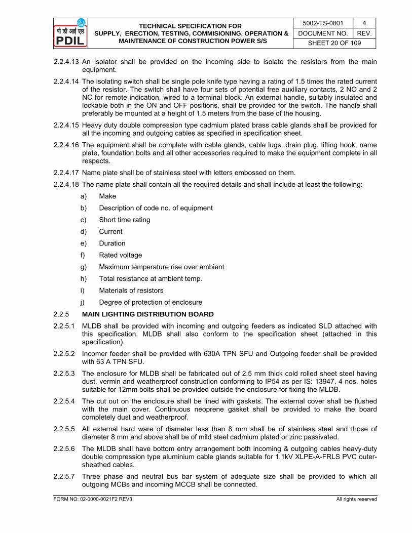
TECHNICAL SPECIFICATION FOR SUPPLY, ERECTION, TESTING, COMMISIONING, OPERATION &
MAINTENANCE OF CONSTRUCTION POWER S/S
5002-TS-0801 4 DOCUMENT NO. REV.
SHEET 20 OF 109
FORM NO: 02-0000-0021F2 REV3 All rights reserved
2.2.4.13 An isolator shall be provided on the incoming side to isolate the resistors from the main equipment.
2.2.4.14 The isolating switch shall be single pole knife type having a rating of 1.5 times the rated current of the resistor. The switch shall have four sets of potential free auxiliary contacts, 2 NO and 2 NC for remote indication, wired to a terminal block. An external handle, suitably insulated and lockable both in the ON and OFF positions, shall be provided for the switch. The handle shall preferably be mounted at a height of 1.5 meters from the base of the housing.
2.2.4.15 Heavy duty double compression type cadmium plated brass cable glands shall be provided for all the incoming and outgoing cables as specified in specification sheet.
2.2.4.16 The equipment shall be complete with cable glands, cable lugs, drain plug, lifting hook, name plate, foundation bolts and all other accessories required to make the equipment complete in all respects.
2.2.4.17 Name plate shall be of stainless steel with letters embossed on them. 2.2.4.18 The name plate shall contain all the required details and shall include at least the following:
a) Make
b) Description of code no. of equipment
c) Short time rating
d) Current
e) Duration
f) Rated voltage
g) Maximum temperature rise over ambient
h) Total resistance at ambient temp.
i) Materials of resistors
j) Degree of protection of enclosure 2.2.5 MAIN LIGHTING DISTRIBUTION BOARD 2.2.5.1 MLDB shall be provided with incoming and outgoing feeders as indicated SLD attached with
this specification. MLDB shall also conform to the specification sheet (attached in this specification).
2.2.5.2 Incomer feeder shall be provided with 630A TPN SFU and Outgoing feeder shall be provided with 63 A TPN SFU.
2.2.5.3 The enclosure for MLDB shall be fabricated out of 2.5 mm thick cold rolled sheet steel having dust, vermin and weatherproof construction conforming to IP54 as per IS: 13947. 4 nos. holes suitable for 12mm bolts shall be provided outside the enclosure for fixing the MLDB.
2.2.5.4 The cut out on the enclosure shall be lined with gaskets. The external cover shall be flushed with the main cover. Continuous neoprene gasket shall be provided to make the board completely dust and weatherproof.
2.2.5.5 All external hard ware of diameter less than 8 mm shall be of stainless steel and those of diameter 8 mm and above shall be of mild steel cadmium plated or zinc passivated.
2.2.5.6 The MLDB shall have bottom entry arrangement both incoming & outgoing cables heavy-duty double compression type aluminium cable glands suitable for 1.1kV XLPE-A-FRLS PVC outer-sheathed cables.
2.2.5.7 Three phase and neutral bus bar system of adequate size shall be provided to which all outgoing MCBs and incoming MCCB shall be connected.

TECHNICAL SPECIFICATION FOR SUPPLY, ERECTION, TESTING, COMMISIONING, OPERATION &
MAINTENANCE OF CONSTRUCTION POWER S/S
5002-TS-0801 4 DOCUMENT NO. REV.
SHEET 21 OF 109
FORM NO: 02-0000-0021F2 REV3 All rights reserved
2.2.5.8 The internal control wiring shall be carried out by means of single core PVC insulated 2.5 sq. mm stranded copper conductor cables.
2.2.5.9 Individual earth terminals shall be provided for the earth conductor of the outgoing cables beside the phase and neutral terminals.
2.2.5.10 Suitable label inscription consisting of black Perspex with engraving for the board and circuit nos. of all outgoing feeders shall be provided. The label inscription of the board shall contain description and code no.
2.2.5.11 Two earthing terminals outside the board shall be provided.
2.2.5.12 The board shall be complete with terminal block, cable glands, cable lugs and other accessories as required.
2.2.5.13 MLDB shall have separate sections of bus bars for indoor and outdoor lighting. Outdoor bus sections shall be connected by means of 630A contactor operated through photo-cells and astro-timer.
2.2.5.14 Manual by-pass circuit for outdoor lighting shall be wired up to a switch located in electrical control room/shift office, so that outdoor lighting can be switched ON or OFF manually to override the automatic switching.
2.2.5.15 All outdoor lighting fixtures including aviation lights and outside lighting of Sub-Stations, Offices etc., shall receive power from outdoor lighting bus.
2.2.6 LIGHTING SUB DISTRIBUTION BOARD 2.2.6.1 LSDB shall be provided with incoming and outgoing feeders as indicated SLD attached with
this specification and specification sheet (attached in this specification) having IP-65 degree of protection.
2.2.6.2 Incomer feeder shall be provided with 63A TP and Switched Neutral SFU and 3 nos. feeder circuit of 63A DP MCB having 9 Nos. outgoing of 16 A DP MCB (i.e. 3 nos. 16 A DP MCB per circuit).
2.2.6.3 The enclosure for LSDB shall be fabricated out of 2.5 mm thick cold rolled sheet steel having dust, vermin and weatherproof construction conforming to IP54 as per IS: 13947. 4 nos. holes suitable for 12mm bolts shall be provided outside the enclosure for fixing the LSDB.
2.2.6.4 The miniature circuit breakers (MCBs) shall be so mounted inside the enclosure that their operating knobs project outside for ease of operation. The cut out for the knobs on the enclosure shall be lined with gaskets. For further protection against ingress of dust, the portion where the knobs have protruded out shall be provided with another external cover, internally hinged at the top, gravity operated and with a knurled knob at the bottom. The external cover shall be flushed with the main cover. Continuous neoprene gasket shall be provided to make the board completely dust and weatherproof.
2.2.6.5 All external hard ware of diameter less than 8 mm shall be of stainless steel and those of diameter 8 mm and above shall be of mild steel cadmium plated or zinc passivated.
2.2.6.6 The LSDB shall have top entry arrangement for outgoing cables and bottom entry for incoming cable provided with heavy-duty double compression type aluminium cable glands suitable for 1.1 KV XLPE-A-FRLS PVC outer-sheathed cables.
2.2.6.7 Three phase and neutral bus bar system of adequate size shall be provided to which all outgoing and incoming MCBs shall be connected.
2.2.6.8 The internal wiring shall be carried out by means of single core PVC insulated 2.5 sq. mm stranded copper conductor cables.
2.2.6.9 Individual earth terminals shall be provided for the earth conductor of the out going cables beside the phase and neutral terminals.
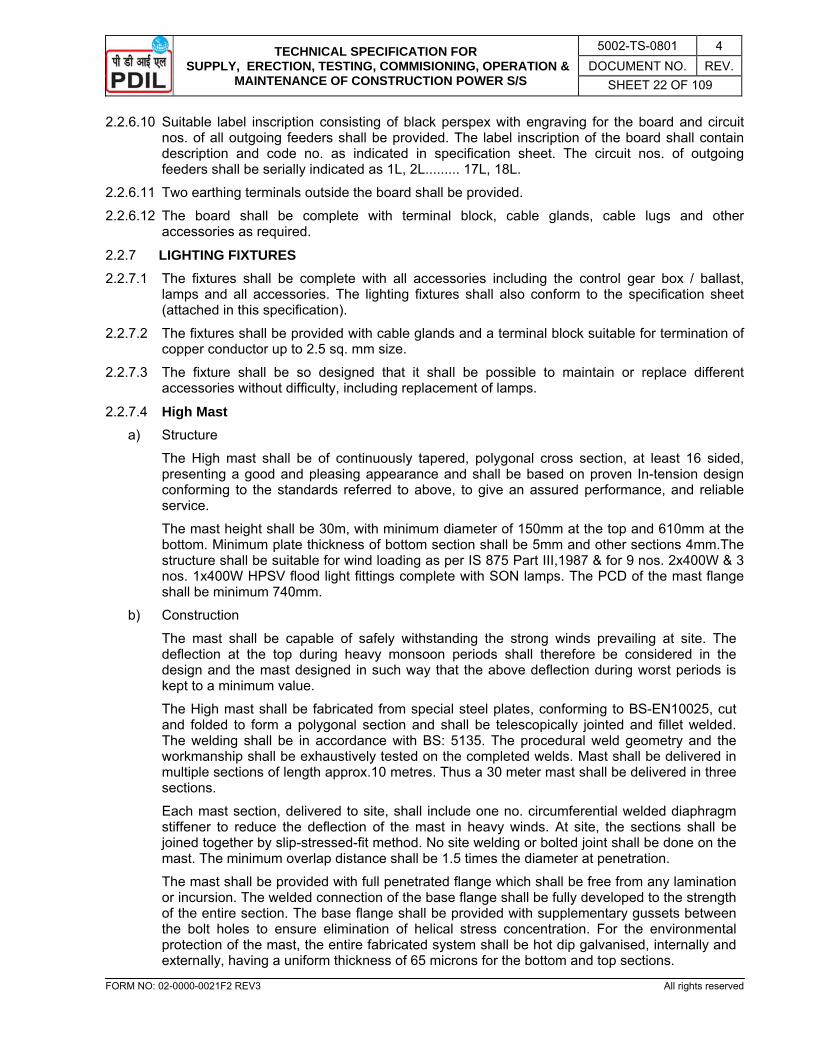
TECHNICAL SPECIFICATION FOR SUPPLY, ERECTION, TESTING, COMMISIONING, OPERATION &
MAINTENANCE OF CONSTRUCTION POWER S/S
5002-TS-0801 4 DOCUMENT NO. REV.
SHEET 22 OF 109
FORM NO: 02-0000-0021F2 REV3 All rights reserved
2.2.6.10 Suitable label inscription consisting of black perspex with engraving for the board and circuit nos. of all outgoing feeders shall be provided. The label inscription of the board shall contain description and code no. as indicated in specification sheet. The circuit nos. of outgoing feeders shall be serially indicated as 1L, 2L......... 17L, 18L.
2.2.6.11 Two earthing terminals outside the board shall be provided.
2.2.6.12 The board shall be complete with terminal block, cable glands, cable lugs and other accessories as required.
2.2.7 LIGHTING FIXTURES 2.2.7.1 The fixtures shall be complete with all accessories including the control gear box / ballast,
lamps and all accessories. The lighting fixtures shall also conform to the specification sheet (attached in this specification).
2.2.7.2 The fixtures shall be provided with cable glands and a terminal block suitable for termination of copper conductor up to 2.5 sq. mm size.
2.2.7.3 The fixture shall be so designed that it shall be possible to maintain or replace different accessories without difficulty, including replacement of lamps.
2.2.7.4 High Mast a) Structure
The High mast shall be of continuously tapered, polygonal cross section, at least 16 sided, presenting a good and pleasing appearance and shall be based on proven In-tension design conforming to the standards referred to above, to give an assured performance, and reliable service.
The mast height shall be 30m, with minimum diameter of 150mm at the top and 610mm at the bottom. Minimum plate thickness of bottom section shall be 5mm and other sections 4mm.The structure shall be suitable for wind loading as per IS 875 Part III,1987 & for 9 nos. 2x400W & 3 nos. 1x400W HPSV flood light fittings complete with SON lamps. The PCD of the mast flange shall be minimum 740mm.
b) Construction
The mast shall be capable of safely withstanding the strong winds prevailing at site. The deflection at the top during heavy monsoon periods shall therefore be considered in the design and the mast designed in such way that the above deflection during worst periods is kept to a minimum value.
The High mast shall be fabricated from special steel plates, conforming to BS-EN10025, cut and folded to form a polygonal section and shall be telescopically jointed and fillet welded. The welding shall be in accordance with BS: 5135. The procedural weld geometry and the workmanship shall be exhaustively tested on the completed welds. Mast shall be delivered in multiple sections of length approx.10 metres. Thus a 30 meter mast shall be delivered in three sections.
Each mast section, delivered to site, shall include one no. circumferential welded diaphragm stiffener to reduce the deflection of the mast in heavy winds. At site, the sections shall be joined together by slip-stressed-fit method. No site welding or bolted joint shall be done on the mast. The minimum overlap distance shall be 1.5 times the diameter at penetration.
The mast shall be provided with full penetrated flange which shall be free from any lamination or incursion. The welded connection of the base flange shall be fully developed to the strength of the entire section. The base flange shall be provided with supplementary gussets between the bolt holes to ensure elimination of helical stress concentration. For the environmental protection of the mast, the entire fabricated system shall be hot dip galvanised, internally and externally, having a uniform thickness of 65 microns for the bottom and top sections.

TECHNICAL SPECIFICATION FOR SUPPLY, ERECTION, TESTING, COMMISIONING, OPERATION &
MAINTENANCE OF CONSTRUCTION POWER S/S
5002-TS-0801 4 DOCUMENT NO. REV.
SHEET 23 OF 109
FORM NO: 02-0000-0021F2 REV3 All rights reserved
c) Door Opening
An adequate door opening of size 1000mm x 300mm shall be provided at the base of the mast and the opening shall be such that it permits clear access to equipment like winches, cables, plug and socket, etc. and also facilitate easy removal of the winch. The door opening shall be complete with a close fitting, vandal resistant, weather proof door, provided with a heavy duty double internal lock with special paddle key.
The door opening shall be carefully designed and reinforced with welded steel section, so that mast section at the base shall be unaffected and undue buckling of the cut portion is prevented.
d) Dynamic Loading for the Mast
The mast structure shall be suitable to sustain an assumed reaction arising from a wind speed as per IS: 875 (three second gust), and shall be measured at height of 10m above ground level. The design life of the mast shall be a minimum of 25 years. Wind excited oscillations shall be dampened by the method of construction and adequate allowance shall be made for the related stresses.
e) Earthing Terminals
3 Nos. earthing terminals, one for lightning protection and other two for electrical earthing of the mast, using 12 mm dia. stainless steel bolts shall be provided at convenient location on the base of the mast.
f) Lantern Carriage
i) Fabrication
A fabricated Lantern Carriage shall be provided for fixing and holding the flood light fittings and control gear boxes. The Lantern Carriage shall be of special design and shall be of steel tube construction, the tubes acting as conduits for wires, with holes fully protected by grommets. The Lantern Carriage shall be so designed and fabricated to hold the required number of flood light fittings and the control gear boxes, and also have a perfect self balance. The Lantern Carriage shall be fabricated in two halves and joined by bolted flanges with stainless steel bolts and plastic lock type stainless steel nuts to enable easy installation or removal from the erected mast. The inner lining of the carriage shall be provided with protective PVC arrangement, so that no damage is caused to the surface of the mast during raising and lowering operation of the carriage. The entire Lantern Carriage shall be hot dip galvanised after fabrication.
ii) Junction Box Weather proof junction box with IP65 enclosure, made of cast Aluminium shall be provided on the Carriage assembly as required, from which the inter-connections to the designed number of the flood light luminaries and associated control gears fixed on the carriage, shall be made.
g) Raising and lowering mechanism
For the installation and maintenance of the luminaries and lamps, it will be necessary to lower and raise the Lantern Carriage assembly. To enable this, a suitable winch arrangement shall be provided, with the winch fixed at the base of the mast and the specially designed head frame assembly at the top.
i) Winch The winch shall be of completely self sustaining type, without the need for brake shoe, springs or clutches. Each driving spindle of the winch shall be positively locked when not in use, gravity activated PAWLS. Individual drum also should be operated for fine adjustment of lantern carriage. The capacity, operating speed, safe working load of the winch and the
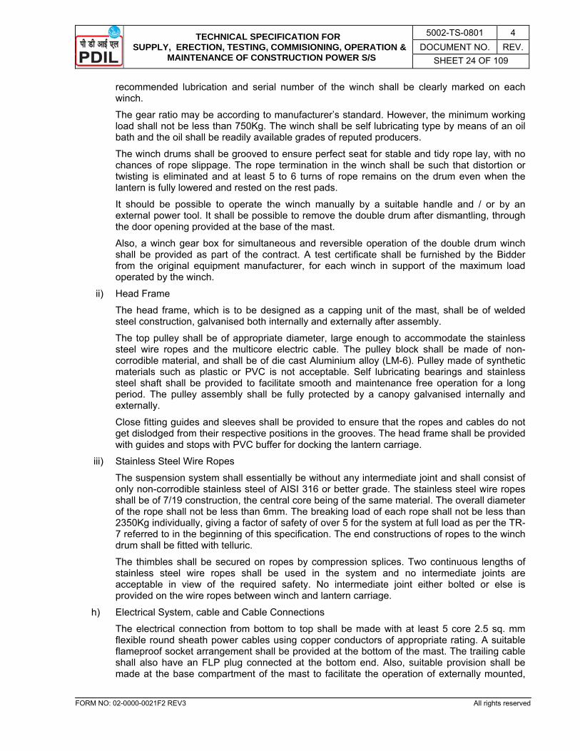
TECHNICAL SPECIFICATION FOR SUPPLY, ERECTION, TESTING, COMMISIONING, OPERATION &
MAINTENANCE OF CONSTRUCTION POWER S/S
5002-TS-0801 4 DOCUMENT NO. REV.
SHEET 24 OF 109
FORM NO: 02-0000-0021F2 REV3 All rights reserved
recommended lubrication and serial number of the winch shall be clearly marked on each winch. The gear ratio may be according to manufacturer’s standard. However, the minimum working load shall not be less than 750Kg. The winch shall be self lubricating type by means of an oil bath and the oil shall be readily available grades of reputed producers. The winch drums shall be grooved to ensure perfect seat for stable and tidy rope lay, with no chances of rope slippage. The rope termination in the winch shall be such that distortion or twisting is eliminated and at least 5 to 6 turns of rope remains on the drum even when the lantern is fully lowered and rested on the rest pads. It should be possible to operate the winch manually by a suitable handle and / or by an external power tool. It shall be possible to remove the double drum after dismantling, through the door opening provided at the base of the mast.
Also, a winch gear box for simultaneous and reversible operation of the double drum winch shall be provided as part of the contract. A test certificate shall be furnished by the Bidder from the original equipment manufacturer, for each winch in support of the maximum load operated by the winch.
ii) Head Frame
The head frame, which is to be designed as a capping unit of the mast, shall be of welded steel construction, galvanised both internally and externally after assembly.
The top pulley shall be of appropriate diameter, large enough to accommodate the stainless steel wire ropes and the multicore electric cable. The pulley block shall be made of non-corrodible material, and shall be of die cast Aluminium alloy (LM-6). Pulley made of synthetic materials such as plastic or PVC is not acceptable. Self lubricating bearings and stainless steel shaft shall be provided to facilitate smooth and maintenance free operation for a long period. The pulley assembly shall be fully protected by a canopy galvanised internally and externally.
Close fitting guides and sleeves shall be provided to ensure that the ropes and cables do not get dislodged from their respective positions in the grooves. The head frame shall be provided with guides and stops with PVC buffer for docking the lantern carriage.
iii) Stainless Steel Wire Ropes
The suspension system shall essentially be without any intermediate joint and shall consist of only non-corrodible stainless steel of AISI 316 or better grade. The stainless steel wire ropes shall be of 7/19 construction, the central core being of the same material. The overall diameter of the rope shall not be less than 6mm. The breaking load of each rope shall not be less than 2350Kg individually, giving a factor of safety of over 5 for the system at full load as per the TR-7 referred to in the beginning of this specification. The end constructions of ropes to the winch drum shall be fitted with telluric.
The thimbles shall be secured on ropes by compression splices. Two continuous lengths of stainless steel wire ropes shall be used in the system and no intermediate joints are acceptable in view of the required safety. No intermediate joint either bolted or else is provided on the wire ropes between winch and lantern carriage.
h) Electrical System, cable and Cable Connections
The electrical connection from bottom to top shall be made with at least 5 core 2.5 sq. mm flexible round sheath power cables using copper conductors of appropriate rating. A suitable flameproof socket arrangement shall be provided at the bottom of the mast. The trailing cable shall also have an FLP plug connected at the bottom end. Also, suitable provision shall be made at the base compartment of the mast to facilitate the operation of externally mounted,

TECHNICAL SPECIFICATION FOR SUPPLY, ERECTION, TESTING, COMMISIONING, OPERATION &
MAINTENANCE OF CONSTRUCTION POWER S/S
5002-TS-0801 4 DOCUMENT NO. REV.
SHEET 25 OF 109
FORM NO: 02-0000-0021F2 REV3 All rights reserved
electrically operated FLP power tool for raising and lowering of the lantern carriage assembly. The trailing cables at the top shall be terminated in the weather proof junction box.
i) Power Tool for the Winch
A suitable, high powered, electrically driven, flameproof, integral mounted power tool, with manual handle together with an operating stand shall be supplied for the raising and lowering of the lantern carriage for maintenance purposes. The speed of the power tool may, preferably, be slow of 1.5 to 1.8 metre/minute, so that vibrations associated with high speed operation are avoided. The power tool shall be single speed, provided with a flameproof motor of required rating, suitable for trolley mounting. The power tool shall be supplied with suitable reversible starter in flameproof enclosure. The capacity and speed of the electric motor used in the power tool shall be suitable for the lifting of the design load installed on the lantern carriage. The power tool trolley shall be so designed that it will not only be self supporting but also aligns the power tool perfectly with respect to the winch spindle during the operations. Also, a handle for the manual operation of the winch in case of problems with electrically operated tool, shall be provided and shall incorporate a torque limiter.
j) Lightning Finial
One number heavy duty, hot dip galvanised, lightning finial shall be provided for each mast. The lightning finial shall be minimum 1.2m in length and shall be provided at the centre of the head frame. It shall be bolted solidly to the head frame to get a direct conducting path to the earth through the mast body. The lightning finial shall not be provided on the lantern carriage under any circumstances in view of safety of the system.
k) Luminaries
i) Each mast shall be fitted with required numbers of specially designed non integral type high mast luminaries (IP-65) complete with separate control gear box (IP-65) suitable for 400W HPSV lamps. Two types of fittings shall be used, viz. 2X400W HPSV (asymmetrical) and 1X400W HPSV (symmetrical).
ii) Twin dome LED type (2x40W) Aviation Obstruction Lights of reliable design and reputed manufacturer shall be provided on top of each mast. It shall have cast aluminium housing finished in aviation yellow colour, suitable rated step-up transformer, thick glass dome mounted on cast aluminium ring and spring loaded high tension porcelain socket fitted with neon cold cathode helix light source. The light source shall be designed to give Omni-directional red colour light distribution to have maximum light output in the zone between 10oC to 90oC above horizontal plane.
2.2.7.5 HPSV Flood Lighting Fixtures a) The fixtures shall be in weatherproof execution suitable for high pressure mercury / sodium
vapour lamp and shall comprise of epoxy stove enamelled, cast aluminium alloy body, a clear heat resistant flat toughened glass, an anodised mirror polished aluminium reflector and a focussing device.
b) The fixtures shall be having an arrangement for rotation on both horizontal and vertical planes and locking in any desired position.
c) The complete unit shall be mounted on a heavy base of cast iron for fixing the fixture on a structural platform.
d) All cast iron and M.S. structural provided in the fixture shall be epoxy painted.
e) A separate control gear box suitable for the rating of the lamp specified shall be supplied along with the fixture.
f) The control gearbox for flood light fixture shall be made of cast aluminium and shall consist of ballast and capacitor for power factor improvement. The control gear box shall be provided with

TECHNICAL SPECIFICATION FOR SUPPLY, ERECTION, TESTING, COMMISIONING, OPERATION &
MAINTENANCE OF CONSTRUCTION POWER S/S
5002-TS-0801 4 DOCUMENT NO. REV.
SHEET 26 OF 109
FORM NO: 02-0000-0021F2 REV3 All rights reserved
looping facility. It shall be separate from fixtures and this shall be installed at man height for ease of maintenance.
g) The fixture / control gear box shall have minimum degree of protection equivalent to IP65.
h) Dispersive reflectors to be supplied with the fixtures shall be of Aluminium anodized material.
i) Fixture shall be provided with double compression cable glands along with blanking plugs.
2.2.7.6 LED Street Lighting Fixtures a) LED Street Light Fitting with cool white light in Pressure Die Cast Aluminium Housing with UV
Stabilized Poly Carbonate Cover with in-built power unit of 3500 lumen suitable for 240V, 50 Hz, System shall be used.
b) Lighting fixture shall have 50000 hrs. Life Time, CRI>75, IP-65.
2.2.7.7 LED Tube Lighting Fixtures a) High quality LED fluorescent tube twin batten type complete with 2 X 20W tube (T5) eco
friendly, no UV radiation as per the specification tabulated below: Sl. No. Parameter Technical Specification
1. Degree of Protection IP-20
2. Lumen output per Lamp ≥ 2000
3. CCT 6500K
4. Luminous efficacy ≥ 100 lm/watt
5. CRI >80
6. Life ≥ 40000 burning hours
7. PF >0.95
8. THD <10%
2.2.7.8 AVIATION OBSTRUCTION LIGHT a) LED type Low Intensity Aviation Obstruction Light suitable for 240V, 50 Hz supply. It shall be
covered under Indian patent act (Govt of India) No. 188995. Degree of protection shall be IP-65.
b) The fixtures shall have body of corrosion resistant aluminium alloy casting and shall be suitable for outdoor use and mounting on 40 mm NB G.I. pipe. Necessary electrical threading shall be tapped in the fixture for mounting.
2.2.8 INTERLOCKED TYPE SWITCH SOCKETS 2.2.8.1 Interlocked type switch socket shall be of the types as specified in specification sheet (attached
in this specification). 2.2.8.2 These shall be complete with heavy duty air break switches, HRC fuses, sockets & plugs.
These shall be fully wired and shall be complete with cable glands, lugs, terminals etc. for external connection.
2.2.8.3 The switch socket shall be heavy duty industrial type. The interlocking arrangement shall be such that it is not possible to insert or withdraw the plug with the switch in ‘ON’ position. Switch socket shall also conform to specification sheet (attached in this specification).
2.2.8.4 The switch sockets shall have dust, hose and weather proof construction conforming to IP55 as per IS: 13947 and shall be suitable for outdoor use without any extra protection. All jointing surfaces shall be smoothly machined and of sufficient width to prevent ingress or dust. Further

TECHNICAL SPECIFICATION FOR SUPPLY, ERECTION, TESTING, COMMISIONING, OPERATION &
MAINTENANCE OF CONSTRUCTION POWER S/S
5002-TS-0801 4 DOCUMENT NO. REV.
SHEET 27 OF 109
FORM NO: 02-0000-0021F2 REV3 All rights reserved
the covers shall be provided with continuous gaskets made of neoprene to prevent ingress of dust and moisture.
2.2.8.5 The enclosure of switch sockets and plugs shall be of cast aluminium alloy 4600 and suitable for fixing on wall / structure. A rain-hood shall be offered as an additional protection. Rain hood shall be of the same material as of the main enclosure. Suitable arrangement for looping of cables from one switch socket to the other shall be provided. Necessary terminals, cable glands and lugs for looping shall be provided. Also one no. threaded plug for each switch socket shall be supplied loose.
2.2.8.6 The Air break switches shall be quick make, quick break rotary type and of utilization category AC-23. Switches shall be hand operated from outside the cover. The switch handle shall remain fixed to the front cover while removing the front cover.
2.2.8.7 The sockets shall be provided with link type HRC fuses. The fuses shall be capable of withstanding a short circuit current of 50 KA and shall be delayed action type. These shall be mounted on a shrouded base.
2.2.8.8 The socket outlet shall be located in the lower part of the enclosure and shall be provided with a threaded aluminium cover attached to the body with SS chain, to protect the socket after extraction of the plug. Spring loaded automatic shutter shall not be acceptable.
2.2.8.9 The plugs shall be so constructed that these can be easily fitted in to the socket outlets and shall be provided with knurled knob arrangement for screwing on the body of the socket so that it can be securely fixed on the top. The plug base and cover shall be firmly secured to each other and shall be sufficiently robust in construction to withstand normal usage. The plug and socket contacts shall be self-aligning type with best electrical continuity.
2.2.8.10 The plug shall be provided with cable entry suitable for receiving TRS flexible heavy duty copper conductor cable of specified size. The arrangement shall be such that the conductors are relieved from strain including twisting where they are connected to the terminals and that the outer surface of the cable at the place of entry is not damaged.
2.2.9 JUNCTION BOXES 2.2.9.1 Junction boxes shall be used for looping of lighting cables in the lighting circuit of fluorescent
fixtures. Junction boxes shall be made of cast aluminium having IP55 degree of protection as per IS: 2147.
2.2.9.2 Junction boxes shall be liberally dimensioned having minimum internal dia. of 120 mm.
2.2.9.3 The junction boxes shall be 4 way, dome cover type, suitable for mounting on surface or wall complete with mounting accessories, 6 nos. 16 A terminals fitted on DMC moulded terminal block with shorting links, 3 nos. cable glands suitable for 3x2.5 sq. mm2 copper conductor XLPE-A-FRLS PVC cable, one no. threaded plug and two external earthing terminals.
2.2.9.4 Cable glands & plugs shall be of hose proof, single compression type and shall be of rolled aluminium.
2.2.10 Wall Mounting Type Distribution Boards 2.2.10.1 Wall mounting type distribution boards such as Welding Socket Distribution Board (WSDB)
shall be provided with incoming and outgoing feeder as indicated in single line diagrams (Drg. Nos. 5002-1202).
2.2.10.2 400A, 50kA for 1 sec. 3 phase & neutral Al bus bar system for WSDB shall be provided to which all outgoing & incoming feeders shall be connected.
2.2.10.3 These shall be fabricated out of 2.5 mm thick CRCA sheet steel. These shall have dust & vermin proof construction conforming as per IS: 13947. The front cover shall be provided with concealed type hinges. The mating surfaces shall be provided with non- deteriorating neoprene gaskets without any discontinuity.

TECHNICAL SPECIFICATION FOR SUPPLY, ERECTION, TESTING, COMMISIONING, OPERATION &
MAINTENANCE OF CONSTRUCTION POWER S/S
5002-TS-0801 4 DOCUMENT NO. REV.
SHEET 28 OF 109
FORM NO: 02-0000-0021F2 REV3 All rights reserved
2.2.10.4 The two earthing terminals outside the board shall be provided.
2.2.10.5 The board shall be complete with terminal blocks, double compression rolled Al cable glands, cable lugs and other accessories as required.
2.2.11 LIGHTING POLES 2.2.11.1 Lighting pole shall be steel tubular swaged type conforming to designation 410 SP-3 as per IS:
2713 complete with base plate, threaded stud with nuts & washers for earthing, finial taper plug, bracket on the overhang portion for fixing of lighting fixtures bolts, nuts and screws as required shall be provided.
2.2.11.2 The outer & inner portions of the poles for ground installation shall have bituminous compound coating at the bottom after galvanising.
2.2.11.3 Zinc coating shall be done by hot dip galvanising process as per IS: 2629 and shall be min. 610 gm / sq. metre.
2.2.11.4 Foundation depth for 5m and 9 m pole shall be 1250mm and 1500mm respectively as per relevant IS.
2.2.11.5 The poles shall be subjected to min. following tests:
- Thickness of galvanising (min. 80 microns)
- Drop test as per IS: 2713.
- Deflection test as per IS: 2713. 2.2.12 HT POWER, LT POWER & CONTROL CABLE 2.2.12.1 All HT power cables shall be made of stranded aluminium conductor with XLPE insulation, PVC
inner sheathed, armoured, PVC outer sheathed FRLS type, conductor screen, insulation screen and construction as per IS: 7098 (Part 2) and as specified in the specification Sheet (attached in this specification). HT cables shall be of earthed / unearthed type as specified in the specification Sheet.
2.2.12.2 All LT power cables shall be with stranded aluminium / copper conductor with XLPE insulation, PVC inner sheathed, armoured, PVC outer sheathed FRLS type and construction as per IS: 7098 (Part 1) and as specified in the specification Sheet (attached in this specification).
2.2.12.3 All control cables shall be stranded copper conductor with XLPE insulation, PVC inner sheathed, armoured, PVC outer sheathed FRLS type and construction as per IS: 7098 (Part 1) and as specified in the specification Sheet (attached in this specification).
2.2.12.4 All control cables cores shall be identified with numerical core numbers printed on core instead of colours.
2.2.12.5 All cables shall be armoured and shall have extruded inner and outer sheath.
2.2.13 CABLE TRAYS 2.2.13.1 Prefabricated perforated Al cable trays and its accessories such as coupler plates, risers,
bends etc. shall be fabricated from 4.0 mm thick Al sheets.
2.2.13.2 The finished tray and accessories shall be free from sharp edges and corners, burrs and unevenness.
2.2.13.3 Each straight length and bed shall be supplied with two coupling plates fitted at each side channel at one end. The couplings plates shall be complete with bolts, nuts and washers fitted at other four holes for fixing to adjoining member. Coupling plate shall be designed to permit longitudinal adjustment up to ±10 mm and skew up to 10°.

TECHNICAL SPECIFICATION FOR SUPPLY, ERECTION, TESTING, COMMISIONING, OPERATION &
MAINTENANCE OF CONSTRUCTION POWER S/S
5002-TS-0801 4 DOCUMENT NO. REV.
SHEET 29 OF 109
FORM NO: 02-0000-0021F2 REV3 All rights reserved
2.2.14 MOUNTING STRUCTURES
Switch sockets, cable trays, DBs, Feeder Pillar etc shall be mounted / supported on suitable structure fabricated out of standard sections of mild steel, i.e. channels, angels, flats etc conforming to IS: 266.
2.3 PAINTING 2.3.1 The equipment surface to be painted shall be pre-treated to remove all dust, scale and foreign
adhering matter by suitable treatment.
2.3.2 All metal surfaces shall be painted with two coats of suitable anti-rust paint followed by two coats of anticorrosive epoxy paints.
2.3.3 All paints shall be carefully selected to withstand tropical heat and extremes of weather. The paint shall not scale off, crinkle or be removed by abrasion due to normal handling.
2.3.4 Unless otherwise specified, the finishing shade shall be light gray having No.631 as per IS-5.
2.4 TESTING 2.4.1 All equipment shall be routine tested as per relevant standards in presence of owner
representative at manufacturer's works before despatch. In addition, the equipment shall be inspected at site for final acceptance.
2.5 DRAWING & DOCUMENTS 2.5.1 All drawings and documents shall have the following descriptions written boldly:
-- Name of Client. -- Name of Consultant i.e. PDIL. -- Enquiry / Order Number with Project/Plant name. -- Equipment Code No. and Description.
2.5.2 At the time of handing over of the installation, the vendor shall supply as built drawings taking into consideration the actual execution carried out at site.
2.5.3 The vendor shall furnish a Bill of Materials covered in their offer. However, this shall be treated for information only and shall not absolve them from his obligation to supply the required items and quantities for making the plant complete as per intent of the specification.
2.5.4 Drawings and documents shall be submitted as per Annexure-I (Sh. 39-40 of this specification) in number of copies as indicated below:
i) With bid: 4
ii) For approval: 6
iii) For information: 8
iv) Final: 8+1CD (CD of vendor generated documents shall only be furnished)
2.6 SPARES 2.6.1 Item wise unit prices of spares as indicated in SOR for two years of operation and maintenance
along with recommended quantity shall be quoted.
2.6.2 Any other spare parts required, but not specified, shall also be offered.
2.6.3 Spare for commissioning as required shall be supplied without any extra cost.
2.6.4 All spare parts shall be identical to the parts used in the offered electrical equipment.
2.7 MAKE OF ELECTRICAL ITEMS 2.7.1 Make of electrical items shall be as follows:
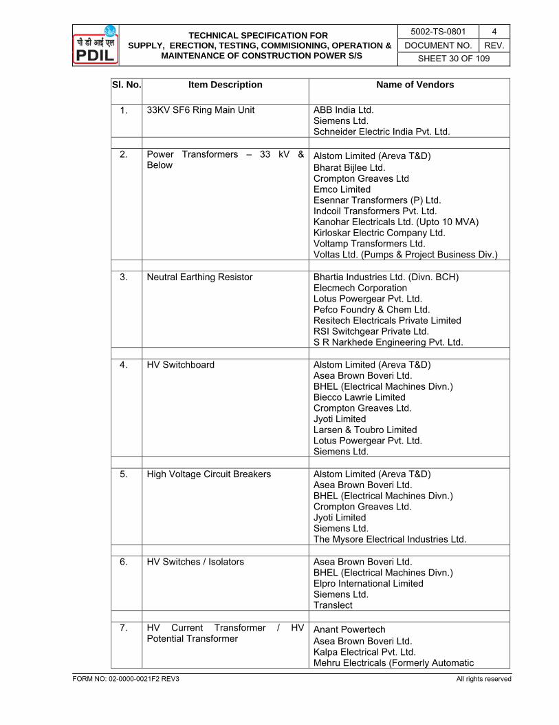
TECHNICAL SPECIFICATION FOR SUPPLY, ERECTION, TESTING, COMMISIONING, OPERATION &
MAINTENANCE OF CONSTRUCTION POWER S/S
5002-TS-0801 4 DOCUMENT NO. REV.
SHEET 30 OF 109
FORM NO: 02-0000-0021F2 REV3 All rights reserved
Sl. No. Item Description Name of Vendors
1. 33KV SF6 Ring Main Unit ABB India Ltd. Siemens Ltd. Schneider Electric India Pvt. Ltd.
2. Power Transformers – 33 kV &
Below Alstom Limited (Areva T&D) Bharat Bijlee Ltd. Crompton Greaves Ltd Emco Limited Esennar Transformers (P) Ltd. Indcoil Transformers Pvt. Ltd. Kanohar Electricals Ltd. (Upto 10 MVA) Kirloskar Electric Company Ltd. Voltamp Transformers Ltd. Voltas Ltd. (Pumps & Project Business Div.)
3. Neutral Earthing Resistor Bhartia Industries Ltd. (Divn. BCH)
Elecmech Corporation Lotus Powergear Pvt. Ltd. Pefco Foundry & Chem Ltd. Resitech Electricals Private Limited RSI Switchgear Private Ltd. S R Narkhede Engineering Pvt. Ltd.
4. HV Switchboard Alstom Limited (Areva T&D)
Asea Brown Boveri Ltd. BHEL (Electrical Machines Divn.) Biecco Lawrie Limited Crompton Greaves Ltd. Jyoti Limited Larsen & Toubro Limited Lotus Powergear Pvt. Ltd. Siemens Ltd.
5. High Voltage Circuit Breakers Alstom Limited (Areva T&D)
Asea Brown Boveri Ltd. BHEL (Electrical Machines Divn.) Crompton Greaves Ltd. Jyoti Limited Siemens Ltd. The Mysore Electrical Industries Ltd.
6. HV Switches / Isolators Asea Brown Boveri Ltd.
BHEL (Electrical Machines Divn.) Elpro International Limited Siemens Ltd. Translect
7. HV Current Transformer / HV
Potential Transformer Anant Powertech Asea Brown Boveri Ltd. Kalpa Electrical Pvt. Ltd. Mehru Electricals (Formerly Automatic
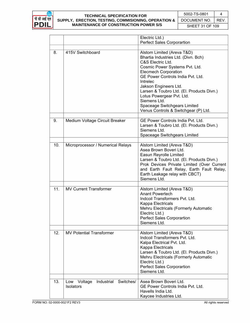
TECHNICAL SPECIFICATION FOR SUPPLY, ERECTION, TESTING, COMMISIONING, OPERATION &
MAINTENANCE OF CONSTRUCTION POWER S/S
5002-TS-0801 4 DOCUMENT NO. REV.
SHEET 31 OF 109
FORM NO: 02-0000-0021F2 REV3 All rights reserved
Electric Ltd.) Perfect Sales Corporartion
8. 415V Switchboard Alstom Limited (Areva T&D)
Bhartia Industries Ltd. (Divn. Bch) C&S Electric Ltd. Cosmic Power Systems Pvt. Ltd. Elecmech Corporation GE Power Controls India Pvt. Ltd. Intrelec Jakson Engineers Ltd. Larsen & Toubro Ltd. (El. Products Divn.) Lotus Powergear Pvt. Ltd. Siemens Ltd. Spaceage Switchgears Limited Venus Controls & Switchgear (P) Ltd.
9. Medium Voltage Circuit Breaker GE Power Controls India Pvt. Ltd.
Larsen & Toubro Ltd. (El. Products Divn.) Siemens Ltd. Spaceage Switchgears Limited
10. Microprocessor / Numerical Relays Alstom Limited (Areva T&D)
Asea Brown Boveri Ltd. Easun Reyrolle Limited Larsen & Toubro Ltd. (El. Products Divn.) Prok Devices Private Limited (Over Current and Earth Fault Relay, Earth Fault Relay, Earth Leakage relay with CBCT) Siemens Ltd.
11. MV Current Transformer Alstom Limited (Areva T&D)
Anant Powertech Indcoil Transformers Pvt. Ltd. Kappa Electricals Mehru Electricals (Formerly Automatic Electric Ltd.) Perfect Sales Corporartion Siemens Ltd.
12. MV Potential Transformer Alstom Limited (Areva T&D)
Indcoil Transformers Pvt. Ltd. Kalpa Electrical Pvt. Ltd. Kappa Electricals Larsen & Toubro Ltd. (El. Products Divn.) Mehru Electricals (Formerly Automatic Electric Ltd.) Perfect Sales Corporartion Siemens Ltd.
13. Low Voltage Industrial Switches/
Isolators Asea Brown Boveri Ltd. GE Power Controls India Pvt. Ltd. Havells India Ltd. Kaycee Industries Ltd.
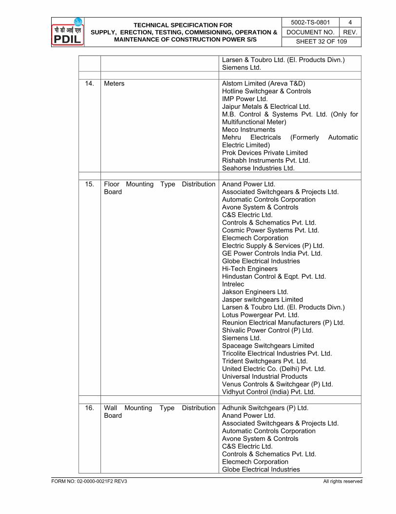
TECHNICAL SPECIFICATION FOR SUPPLY, ERECTION, TESTING, COMMISIONING, OPERATION &
MAINTENANCE OF CONSTRUCTION POWER S/S
5002-TS-0801 4 DOCUMENT NO. REV.
SHEET 32 OF 109
FORM NO: 02-0000-0021F2 REV3 All rights reserved
Larsen & Toubro Ltd. (El. Products Divn.) Siemens Ltd.
14. Meters Alstom Limited (Areva T&D)
Hotline Switchgear & Controls IMP Power Ltd. Jaipur Metals & Electrical Ltd. M.B. Control & Systems Pvt. Ltd. (Only for Multifunctional Meter) Meco Instruments Mehru Electricals (Formerly Automatic Electric Limited) Prok Devices Private Limited Rishabh Instruments Pvt. Ltd. Seahorse Industries Ltd.
15. Floor Mounting Type Distribution
Board Anand Power Ltd. Associated Switchgears & Projects Ltd. Automatic Controls Corporation Avone System & Controls C&S Electric Ltd. Controls & Schematics Pvt. Ltd. Cosmic Power Systems Pvt. Ltd. Elecmech Corporation Electric Supply & Services (P) Ltd. GE Power Controls India Pvt. Ltd. Globe Electrical Industries Hi-Tech Engineers Hindustan Control & Eqpt. Pvt. Ltd. Intrelec Jakson Engineers Ltd. Jasper switchgears Limited Larsen & Toubro Ltd. (El. Products Divn.) Lotus Powergear Pvt. Ltd. Reunion Electrical Manufacturers (P) Ltd. Shivalic Power Control (P) Ltd. Siemens Ltd. Spaceage Switchgears Limited Tricolite Electrical Industries Pvt. Ltd. Trident Switchgears Pvt. Ltd. United Electric Co. (Delhi) Pvt. Ltd. Universal Industrial Products Venus Controls & Switchgear (P) Ltd. Vidhyut Control (India) Pvt. Ltd.
16. Wall Mounting Type Distribution
Board Adhunik Switchgears (P) Ltd. Anand Power Ltd. Associated Switchgears & Projects Ltd. Automatic Controls Corporation Avone System & Controls C&S Electric Ltd. Controls & Schematics Pvt. Ltd. Elecmech Corporation Globe Electrical Industries

TECHNICAL SPECIFICATION FOR SUPPLY, ERECTION, TESTING, COMMISIONING, OPERATION &
MAINTENANCE OF CONSTRUCTION POWER S/S
5002-TS-0801 4 DOCUMENT NO. REV.
SHEET 33 OF 109
FORM NO: 02-0000-0021F2 REV3 All rights reserved
Havells India Ltd. Hi-Tech Engineers Hindustan Control & Eqpt. Pvt. Ltd. Indiana Current Control Ltd. Indo Asian Fusegear Ltd. Intrelec Jakson Engineers Ltd. Legrand India Ltd. Lotus Powergear Pvt. Ltd. Reunion Electrical Manufacturers (P) Ltd. Shivalic Power Control (P) Ltd. Standard Electricals Limited Tricolite Electrical Industries Pvt. Ltd. Trident Switchgears Pvt. Ltd. Venus Controls & Switchgear (P) Ltd.
17. MCCB Crompton Greaves Ltd.
GE Power Controls India Pvt. Ltd. Havells India Ltd. Larsen & Toubro Ltd. (El. Products Divn.) Siemens Ltd. Spaceage Switchgears Limited Standard Electricals Limited
18. MCB Adhunik Switchgears (P) Ltd.
Havells India Ltd. HPL Electric & Power Pvt. Ltd. Indiana Current Control Ltd. Indo Asian Fusegear Ltd. Legrand India Ltd. S & S Power Switchgear Ltd. Standard Electricals Limited
19. MV ELCB GE Power Controls India Pvt. Ltd.
Havells India Ltd. Indo Asian Fusegear Ltd. Legrand India Ltd. S & S Power Switchgear Ltd. Siemens Ltd. Standard Electricals Limited
20. Fuse Larsen & Toubro Ltd. (El. Products Divn.)
Siemens Ltd. Alstom Power Havells India Ltd.
21. Contactor Larsen & Toubro Ltd. (El. Products Divn.)
Siemens Ltd. 22. Auxiliary Relays ABB India Limited
Alstom Limited (Areva T&D) Easun Reyrolle Limited Jyoti Limited Larsen & Toubro Ltd. (El. Products Divn.)
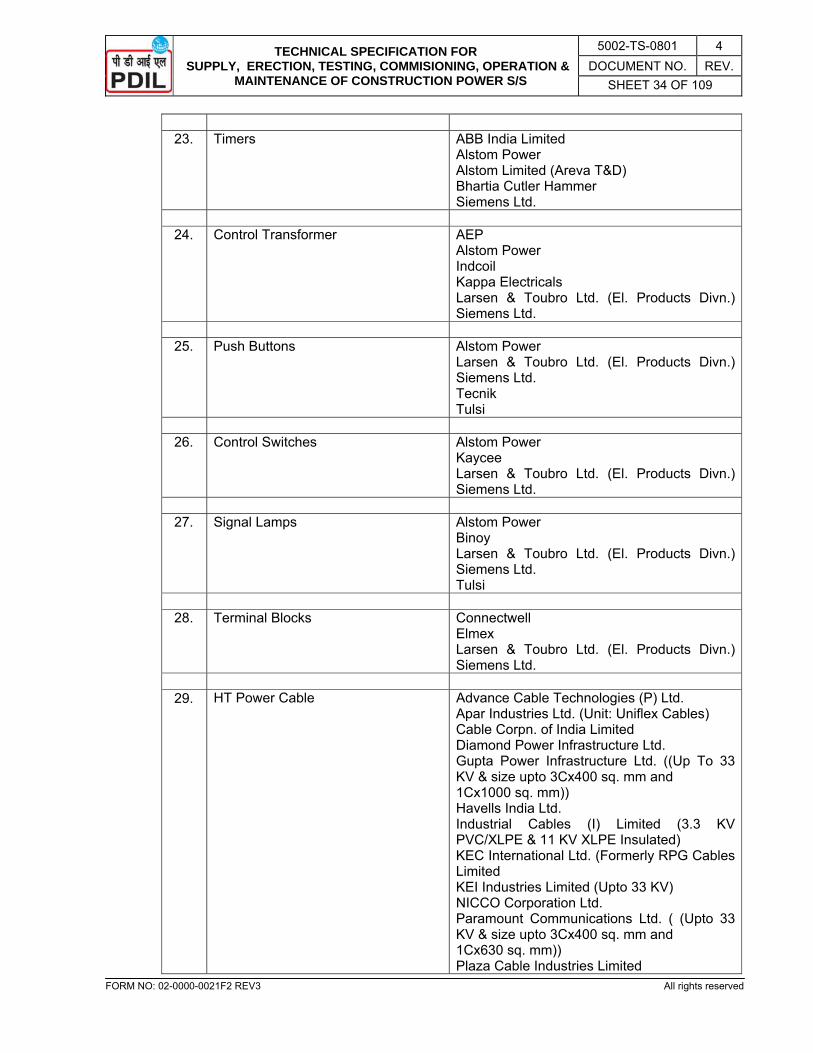
TECHNICAL SPECIFICATION FOR SUPPLY, ERECTION, TESTING, COMMISIONING, OPERATION &
MAINTENANCE OF CONSTRUCTION POWER S/S
5002-TS-0801 4 DOCUMENT NO. REV.
SHEET 34 OF 109
FORM NO: 02-0000-0021F2 REV3 All rights reserved
23. Timers ABB India Limited
Alstom Power Alstom Limited (Areva T&D) Bhartia Cutler Hammer Siemens Ltd.
24. Control Transformer AEP
Alstom Power Indcoil Kappa Electricals Larsen & Toubro Ltd. (El. Products Divn.) Siemens Ltd.
25. Push Buttons Alstom Power
Larsen & Toubro Ltd. (El. Products Divn.) Siemens Ltd. Tecnik Tulsi
26. Control Switches Alstom Power
Kaycee Larsen & Toubro Ltd. (El. Products Divn.) Siemens Ltd.
27. Signal Lamps Alstom Power
Binoy Larsen & Toubro Ltd. (El. Products Divn.) Siemens Ltd. Tulsi
28. Terminal Blocks Connectwell
Elmex Larsen & Toubro Ltd. (El. Products Divn.) Siemens Ltd.
29. HT Power Cable Advance Cable Technologies (P) Ltd.
Apar Industries Ltd. (Unit: Uniflex Cables) Cable Corpn. of India Limited Diamond Power Infrastructure Ltd. Gupta Power Infrastructure Ltd. ((Up To 33 KV & size upto 3Cx400 sq. mm and 1Cx1000 sq. mm)) Havells India Ltd. Industrial Cables (I) Limited (3.3 KV PVC/XLPE & 11 KV XLPE Insulated) KEC International Ltd. (Formerly RPG Cables Limited KEI Industries Limited (Upto 33 KV) NICCO Corporation Ltd. Paramount Communications Ltd. ( (Upto 33 KV & size upto 3Cx400 sq. mm and 1Cx630 sq. mm)) Plaza Cable Industries Limited
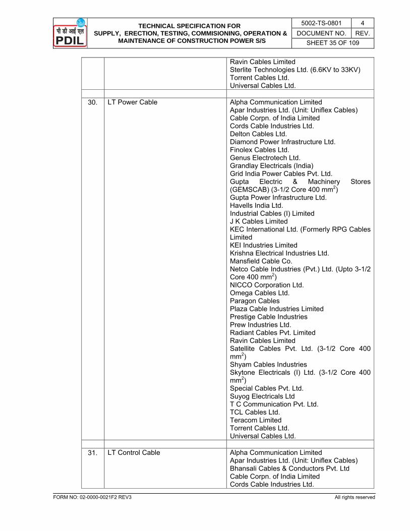
TECHNICAL SPECIFICATION FOR SUPPLY, ERECTION, TESTING, COMMISIONING, OPERATION &
MAINTENANCE OF CONSTRUCTION POWER S/S
5002-TS-0801 4 DOCUMENT NO. REV.
SHEET 35 OF 109
FORM NO: 02-0000-0021F2 REV3 All rights reserved
Ravin Cables Limited Sterlite Technologies Ltd. (6.6KV to 33KV) Torrent Cables Ltd. Universal Cables Ltd.
30. LT Power Cable Alpha Communication Limited
Apar Industries Ltd. (Unit: Uniflex Cables) Cable Corpn. of India Limited Cords Cable Industries Ltd. Delton Cables Ltd. Diamond Power Infrastructure Ltd. Finolex Cables Ltd. Genus Electrotech Ltd. Grandlay Electricals (India) Grid India Power Cables Pvt. Ltd. Gupta Electric & Machinery Stores (GEMSCAB) (3-1/2 Core 400 mm2) Gupta Power Infrastructure Ltd. Havells India Ltd. Industrial Cables (I) Limited J K Cables Limited KEC International Ltd. (Formerly RPG Cables Limited KEI Industries Limited Krishna Electrical Industries Ltd. Mansfield Cable Co. Netco Cable Industries (Pvt.) Ltd. (Upto 3-1/2 Core 400 mm2) NICCO Corporation Ltd. Omega Cables Ltd. Paragon Cables Plaza Cable Industries Limited Prestige Cable Industries Prew Industries Ltd. Radiant Cables Pvt. Limited Ravin Cables Limited Satellite Cables Pvt. Ltd. (3-1/2 Core 400 mm2) Shyam Cables Industries Skytone Electricals (I) Ltd. (3-1/2 Core 400 mm2) Special Cables Pvt. Ltd. Suyog Electricals Ltd T C Communication Pvt. Ltd. TCL Cables Ltd. Teracom Limited Torrent Cables Ltd. Universal Cables Ltd.
31. LT Control Cable Alpha Communication Limited
Apar Industries Ltd. (Unit: Uniflex Cables) Bhansali Cables & Conductors Pvt. Ltd Cable Corpn. of India Limited Cords Cable Industries Ltd.
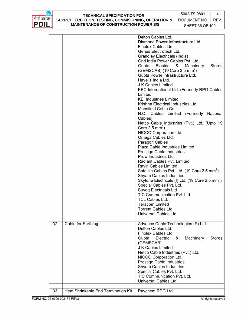
TECHNICAL SPECIFICATION FOR SUPPLY, ERECTION, TESTING, COMMISIONING, OPERATION &
MAINTENANCE OF CONSTRUCTION POWER S/S
5002-TS-0801 4 DOCUMENT NO. REV.
SHEET 36 OF 109
FORM NO: 02-0000-0021F2 REV3 All rights reserved
Delton Cables Ltd. Diamond Power Infrastructure Ltd. Finolex Cables Ltd. Genus Electrotech Ltd. Grandlay Electricals (India) Grid India Power Cables Pvt. Ltd. Gupta Electric & Machinery Stores (GEMSCAB) (19 Core 2.5 mm2) Gupta Power Infrastructure Ltd. Havells India Ltd. J K Cables Limited KEC International Ltd. (Formerly RPG Cables Limited KEI Industries Limited Krishna Electrical Industries Ltd. Mansfield Cable Co. N.C. Cables Limited (Formerly National Cables) Netco Cable Industries (Pvt.) Ltd. (Upto 19 Core 2.5 mm2) NICCO Corporation Ltd. Omega Cables Ltd. Paragon Cables Plaza Cable Industries Limited Prestige Cable Industries Prew Industries Ltd. Radiant Cables Pvt. Limited Ravin Cables Limited Satellite Cables Pvt. Ltd. (19 Core 2.5 mm2) Shyam Cables Industries Skytone Electricals (I) Ltd. (19 Core 2.5 mm2) Special Cables Pvt. Ltd. Suyog Electricals Ltd T C Communication Pvt. Ltd. TCL Cables Ltd. Teracom Limited Torrent Cables Ltd. Universal Cables Ltd.
32. Cable for Earthing Advance Cable Technologies (P) Ltd.
Delton Cables Ltd. Finolex Cables Ltd. Gupta Electric & Machinery Stores (GEMSCAB) J K Cables Limited Netco Cable Industries (Pvt.) Ltd. NICCO Corporation Ltd. Prestige Cable Industries Shyam Cables Industries Special Cables Pvt. Ltd. T C Communication Pvt. Ltd. Universal Cables Ltd.
33. Heat Shrinkable End Termination Kit Raychem RPG Ltd.
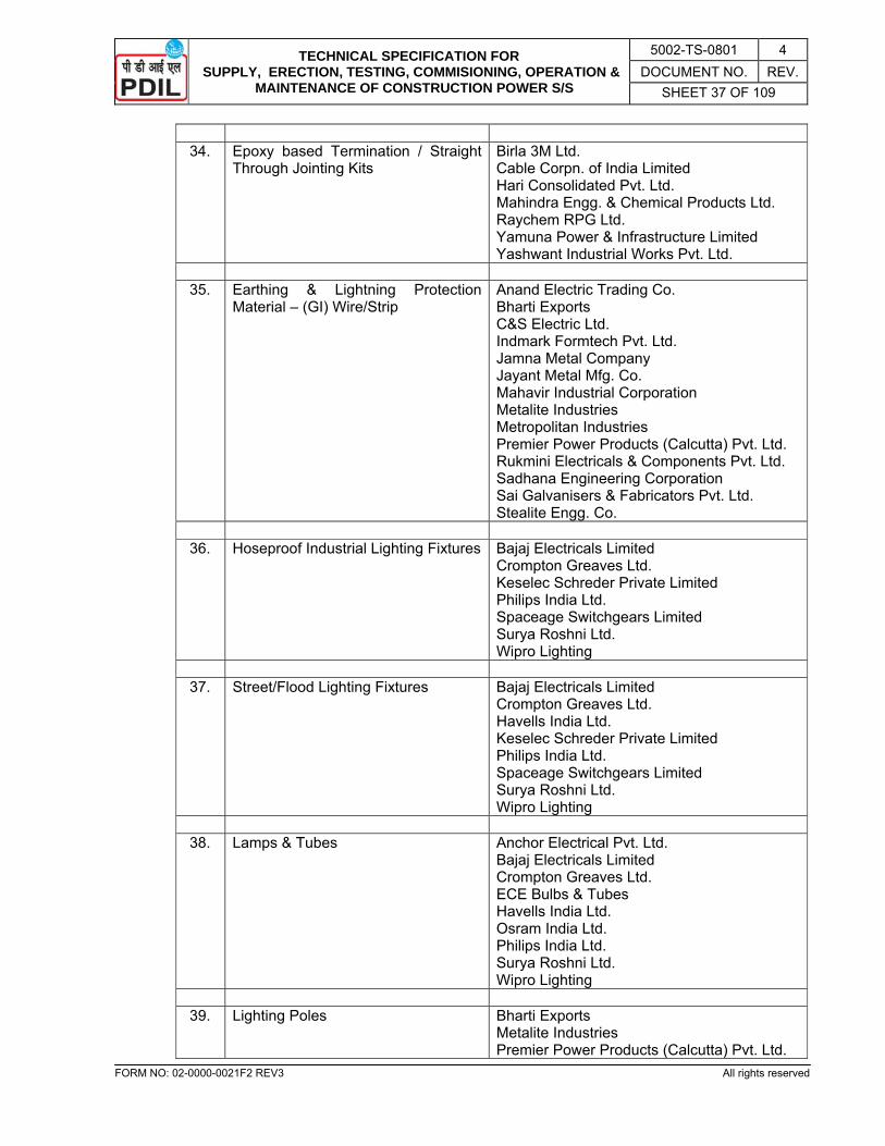
TECHNICAL SPECIFICATION FOR SUPPLY, ERECTION, TESTING, COMMISIONING, OPERATION &
MAINTENANCE OF CONSTRUCTION POWER S/S
5002-TS-0801 4 DOCUMENT NO. REV.
SHEET 37 OF 109
FORM NO: 02-0000-0021F2 REV3 All rights reserved
34. Epoxy based Termination / Straight
Through Jointing Kits Birla 3M Ltd. Cable Corpn. of India Limited Hari Consolidated Pvt. Ltd. Mahindra Engg. & Chemical Products Ltd. Raychem RPG Ltd. Yamuna Power & Infrastructure Limited Yashwant Industrial Works Pvt. Ltd.
35. Earthing & Lightning Protection
Material – (GI) Wire/Strip Anand Electric Trading Co. Bharti Exports C&S Electric Ltd. Indmark Formtech Pvt. Ltd. Jamna Metal Company Jayant Metal Mfg. Co. Mahavir Industrial Corporation Metalite Industries Metropolitan Industries Premier Power Products (Calcutta) Pvt. Ltd. Rukmini Electricals & Components Pvt. Ltd. Sadhana Engineering Corporation Sai Galvanisers & Fabricators Pvt. Ltd. Stealite Engg. Co.
36. Hoseproof Industrial Lighting Fixtures Bajaj Electricals Limited
Crompton Greaves Ltd. Keselec Schreder Private Limited Philips India Ltd. Spaceage Switchgears Limited Surya Roshni Ltd. Wipro Lighting
37. Street/Flood Lighting Fixtures Bajaj Electricals Limited
Crompton Greaves Ltd. Havells India Ltd. Keselec Schreder Private Limited Philips India Ltd. Spaceage Switchgears Limited Surya Roshni Ltd. Wipro Lighting
38. Lamps & Tubes Anchor Electrical Pvt. Ltd.
Bajaj Electricals Limited Crompton Greaves Ltd. ECE Bulbs & Tubes Havells India Ltd. Osram India Ltd. Philips India Ltd. Surya Roshni Ltd. Wipro Lighting
39. Lighting Poles Bharti Exports
Metalite Industries Premier Power Products (Calcutta) Pvt. Ltd.

TECHNICAL SPECIFICATION FOR SUPPLY, ERECTION, TESTING, COMMISIONING, OPERATION &
MAINTENANCE OF CONSTRUCTION POWER S/S
5002-TS-0801 4 DOCUMENT NO. REV.
SHEET 38 OF 109
FORM NO: 02-0000-0021F2 REV3 All rights reserved
Sadhana Engineering Corporation Surya Roshni Ltd.
40. Pre-Fabricated Al-Cable Tray Globe Electrical Industries
Hinustan Vidyut Products Indiana Engg. Works Pvt. Ltd. Indmark Formtech Pvt. Ltd. Jamna Metal Company Kanade Anand Udyog Pvt. Ltd. Maheshwari Electrical Mfrs. (P) Ltd. Metalite Industries Parekh Engineering Company Premier Power Products (Calcutta) Pvt. Ltd. Rukmini Electricals & Components Pvt. Ltd. Sadhana Engineering Corporation Sree Atreya Enterprises Stealite Engg. Co.
41. GI Pipes & Conduits Bharti Exports
Indian tube co. (Tata Div. of Tubes & Pipes) Jindal Pipes Ltd. Meghjyot Enterprises Rukmini Electricals & Components Pvt. Ltd. Steelcraft
42. Industrial Cable Gland Baliga Lighting Equipments Limited
Comet Brass Products Comet Industries Dowell's Electricals Electromac Industries FCG Flameproof Control Gears Pvt. Ltd. (Formerly CEAG Flame Gland-Mech. Industries Power Engg. Co. Quality & Precision Indl. Equipment S J Metal Industries (Jainson)
43. Flameproof Cable Gland Baliga Lighting Equipments Limited
Comet Brass Products Comet Industries Dowell's Electricals Electromac Industries FCG Flameproof Control Gears Pvt. Ltd. (Formerly CEAG Flame FCG Power Industries Ltd. Flameproof Equipments Pvt. Ltd. Flexpro Electricals Pvt. Ltd. Industrial Products Equipment Kaysons Techno Equipments Pvt. Ltd. Power Engg. Co. Prompt Engineering Works Sudhir Switchgears Pvt. Ltd.
44. Cable Lugs Dowell's Electricals
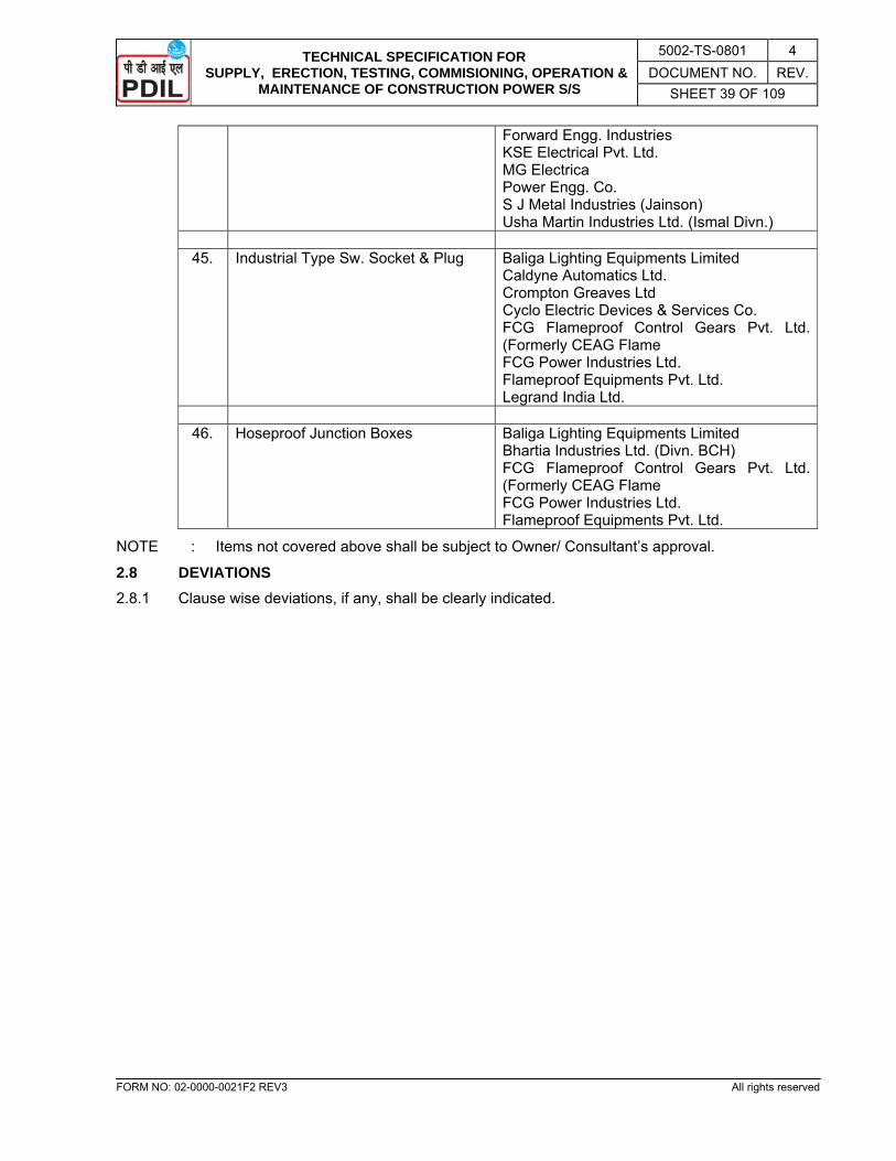
TECHNICAL SPECIFICATION FOR SUPPLY, ERECTION, TESTING, COMMISIONING, OPERATION &
MAINTENANCE OF CONSTRUCTION POWER S/S
5002-TS-0801 4 DOCUMENT NO. REV.
SHEET 39 OF 109
FORM NO: 02-0000-0021F2 REV3 All rights reserved
Forward Engg. Industries KSE Electrical Pvt. Ltd. MG Electrica Power Engg. Co. S J Metal Industries (Jainson) Usha Martin Industries Ltd. (Ismal Divn.)
45. Industrial Type Sw. Socket & Plug Baliga Lighting Equipments Limited
Caldyne Automatics Ltd. Crompton Greaves Ltd Cyclo Electric Devices & Services Co. FCG Flameproof Control Gears Pvt. Ltd. (Formerly CEAG Flame FCG Power Industries Ltd. Flameproof Equipments Pvt. Ltd. Legrand India Ltd.
46. Hoseproof Junction Boxes Baliga Lighting Equipments Limited
Bhartia Industries Ltd. (Divn. BCH) FCG Flameproof Control Gears Pvt. Ltd. (Formerly CEAG Flame FCG Power Industries Ltd. Flameproof Equipments Pvt. Ltd.
NOTE : Items not covered above shall be subject to Owner/ Consultant’s approval.
2.8 DEVIATIONS 2.8.1 Clause wise deviations, if any, shall be clearly indicated.
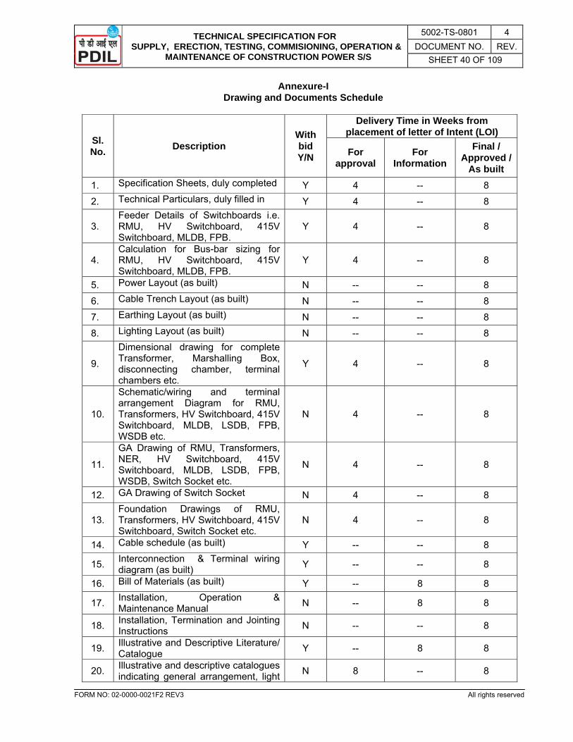
TECHNICAL SPECIFICATION FOR SUPPLY, ERECTION, TESTING, COMMISIONING, OPERATION &
MAINTENANCE OF CONSTRUCTION POWER S/S
5002-TS-0801 4 DOCUMENT NO. REV.
SHEET 40 OF 109
FORM NO: 02-0000-0021F2 REV3 All rights reserved
Annexure-I Drawing and Documents Schedule
Sl. No. Description
With bid Y/N
Delivery Time in Weeks from placement of letter of Intent (LOI)
For approval
For Information
Final / Approved /
As built 1. Specification Sheets, duly completed Y 4 -- 8 2. Technical Particulars, duly filled in Y 4 -- 8
3. Feeder Details of Switchboards i.e. RMU, HV Switchboard, 415V Switchboard, MLDB, FPB.
Y 4 -- 8
4. Calculation for Bus-bar sizing for RMU, HV Switchboard, 415V Switchboard, MLDB, FPB.
Y 4 -- 8
5. Power Layout (as built) N -- -- 8 6. Cable Trench Layout (as built) N -- -- 8 7. Earthing Layout (as built) N -- -- 8 8. Lighting Layout (as built) N -- -- 8
9.
Dimensional drawing for complete Transformer, Marshalling Box, disconnecting chamber, terminal chambers etc.
Y 4 -- 8
10.
Schematic/wiring and terminal arrangement Diagram for RMU, Transformers, HV Switchboard, 415V Switchboard, MLDB, LSDB, FPB, WSDB etc.
N 4 -- 8
11.
GA Drawing of RMU, Transformers, NER, HV Switchboard, 415V Switchboard, MLDB, LSDB, FPB, WSDB, Switch Socket etc.
N 4 -- 8
12. GA Drawing of Switch Socket N 4 -- 8
13. Foundation Drawings of RMU, Transformers, HV Switchboard, 415V Switchboard, Switch Socket etc.
N 4 -- 8
14. Cable schedule (as built) Y -- -- 8
15. Interconnection & Terminal wiring diagram (as built) Y -- -- 8
16. Bill of Materials (as built) Y -- 8 8
17. Installation, Operation & Maintenance Manual N -- 8 8
18. Installation, Termination and Jointing Instructions N -- -- 8
19. Illustrative and Descriptive Literature/ Catalogue Y -- 8 8
20. Illustrative and descriptive catalogues indicating general arrangement, light N 8 -- 8
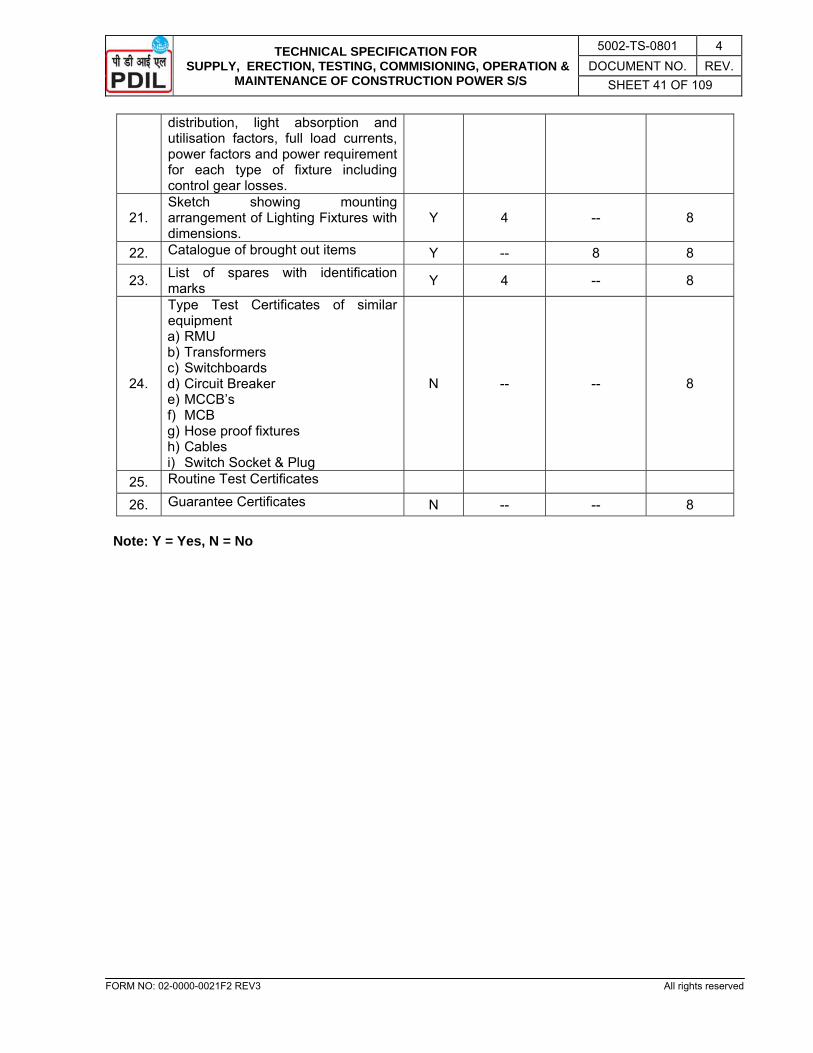
TECHNICAL SPECIFICATION FOR SUPPLY, ERECTION, TESTING, COMMISIONING, OPERATION &
MAINTENANCE OF CONSTRUCTION POWER S/S
5002-TS-0801 4 DOCUMENT NO. REV.
SHEET 41 OF 109
FORM NO: 02-0000-0021F2 REV3 All rights reserved
distribution, light absorption and utilisation factors, full load currents, power factors and power requirement for each type of fixture including control gear losses.
21. Sketch showing mounting arrangement of Lighting Fixtures with dimensions.
Y 4 -- 8
22. Catalogue of brought out items Y -- 8 8
23. List of spares with identification marks Y 4 -- 8
24.
Type Test Certificates of similar equipment a) RMU b) Transformers c) Switchboards d) Circuit Breaker e) MCCB’s f) MCB g) Hose proof fixtures h) Cables i) Switch Socket & Plug
N -- -- 8
25. Routine Test Certificates 26. Guarantee Certificates N -- -- 8
Note: Y = Yes, N = No

TECHNICAL SPECIFICATION FOR SUPPLY, ERECTION, TESTING, COMMISIONING, OPERATION &
MAINTENANCE OF CONSTRUCTION POWER S/S
5002-TS-0801 4 DOCUMENT NO. REV.
SHEET 42 OF 109
FORM NO: 02-0000-0021F2 REV3 All rights reserved
SPECIFICATION SHEET 33KV SF6 INSULATED RING MAIN UNIT (RMU)
CLIENT: M/s HURL, Sindri PROJECT: Pre-project Electrical Works PLANT: Ammonia, Urea & Offsite ISSUED FOR : PROPOSAL ENQUIRY ORDER FINAL
GENERAL AMBIENT CONDITION Ref. Stds. : IS IEC Temp. Max./Min./Design Ref. : 47.7 / 2.3 / 50°C Encl. Docs. : Relative Humidity: 100% Alt. above sea <1000 M Make : ATMOSPHERIC
POLLUTION Dusts : Urea
Maker’s Ref. No. : Vapour : Ammonia
LOCATION Indoor Outdoor
Gr. Floor 1st floor
ADDL. SCOPE Incoming Bus Duct Tie Bus Duct Erection & Comm. Supervision of Erection & Comm.
TESTS: Routine Type Others BASIC DATA
Description 33KV SF6 RMU
REFERENCE DRAWINGS
Single Line Diagram Drg. No. 5002-7411-0985 Feeder Details Sh. No. 42 of this specification P.T. Bus Arrangement
SYSTEM DETAILS
Rated Voltage with variation 33 KV ± 10% Rated Frequency with variation 50Hz ± 5% Highest System Voltage 36KV Combined V & F Variation ± 10% No. of Phases & Wires 3 Phase, 3 Wire Power Frequency withstand voltage 70KV Insulation Level 170KV Fault Level 20KA for 3 sec.Earthing Mode Solidly Earthed
BUS BARS Rating
Continuous 630A Short Time for 3 sec. 20KA for 3 sec.
Type of Insulation SF6 Insulated
CIRCUIT BREAKER
Type Vacuum Circuit Breaker
Breaking Capacity
Symmetrical 20KA for 3 sec. % DC Component 20% (Min.)
Making Capacity ( peak ) 50KA
CONTROL SUPPLY
Closing & Indication 220V DC ** Tripping 220V DC ** Alarm / Signal 220V DC ** Space Heater 240V AC
MISC. DATA
Cable Entry Top / Bottom Bottom Dummy Panel Reqd. Yes / No No Width of Dummy Panel -- No. of Dummy Panel --
PAINTING Type Epoxy Based Shade 631 of IS: 5
Spares Parts Reqd. for a Period of 2 Years ** NOTE: 220V DC power required shall be provided by the vendor through in-built power pack in the feeders having battery back-up of 6 hours. j) Spare power pack with inside and outside isolation shall be provided.
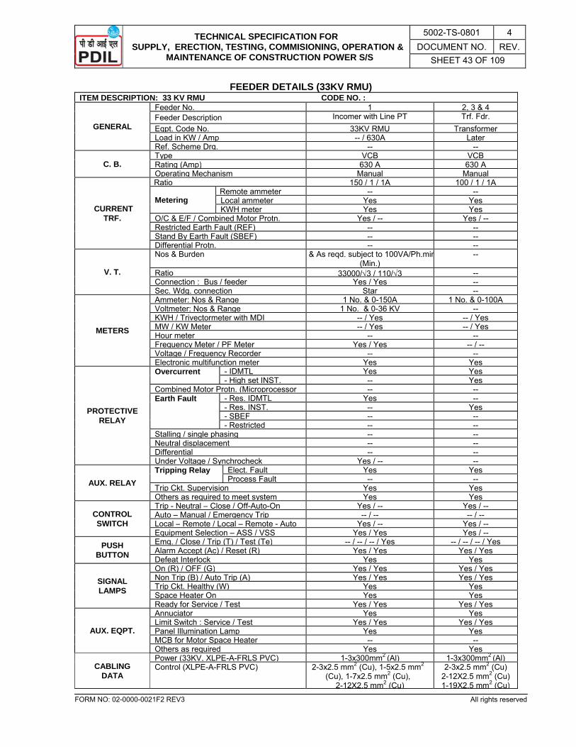
TECHNICAL SPECIFICATION FOR SUPPLY, ERECTION, TESTING, COMMISIONING, OPERATION &
MAINTENANCE OF CONSTRUCTION POWER S/S
5002-TS-0801 4 DOCUMENT NO. REV.
SHEET 43 OF 109
FORM NO: 02-0000-0021F2 REV3 All rights reserved
FEEDER DETAILS (33KV RMU) ITEM DESCRIPTION: 33 KV RMU CODE NO. :
GENERAL
Feeder No. 1 2, 3 & 4Feeder Description Incomer with Line PT Trf. Fdr. Eqpt. Code No. 33KV RMU TransformerLoad in KW / Amp -- / 630A LaterRef. Scheme Drg. -- --
C. B. Type VCB VCBRating (Amp) 630 A 630 AOperating Mechanism Manual Manual
CURRENT TRF.
Ratio 150 / 1 / 1A 100 / 1 / 1A
Metering Remote ammeter -- --Local ammeter Yes YesKWH meter Yes Yes
O/C & E/F / Combined Motor Protn. Yes / -- Yes / --Restricted Earth Fault (REF) -- --Stand By Earth Fault (SBEF) -- --Differential Protn. -- --
V. T.
Nos & Burden & As reqd. subject to 100VA/Ph.min(Min.)
--
Ratio 33000/√3 / 110/√3 --Connection : Bus / feeder Yes / Yes --Sec. Wdg. connection Star --
METERS
Ammeter: Nos & Range 1 No. & 0-150A 1 No. & 0-100AVoltmeter: Nos & Range 1 No. & 0-36 KV --KWH / Trivectormeter with MDI -- / Yes -- / YesMW / KW Meter -- / Yes -- / YesHour meter -- --Frequency Meter / PF Meter Yes / Yes -- / --Voltage / Frequency Recorder -- --Electronic multifunction meter Yes Yes
PROTECTIVE RELAY
Overcurrent - IDMTL Yes Yes- High set INST. -- Yes
Combined Motor Protn. (Microprocessor -- --Earth Fault - Res. IDMTL Yes --
- Res. INST. -- Yes- SBEF -- --- Restricted -- --
Stalling / single phasing -- --Neutral displacement -- --Differential -- --Under Voltage / Synchrocheck Yes / -- --
AUX. RELAY Tripping Relay Elect. Fault Yes Yes
Process Fault -- --Trip Ckt. Supervision Yes YesOthers as required to meet system Yes Yes
CONTROL SWITCH
Trip - Neutral – Close / Off-Auto-On Yes / -- Yes / --Auto – Manual / Emergency Trip -- / -- -- / --Local – Remote / Local – Remote - Auto Yes / -- Yes / --Equipment Selection – ASS / VSS Yes / Yes Yes / --
PUSH BUTTON
Emg. / Close / Trip (T) / Test (Te) -- / -- / -- / Yes -- / -- / -- / YesAlarm Accept (Ac) / Reset (R) Yes / Yes Yes / YesDefeat Interlock Yes Yes
SIGNAL LAMPS
On (R) / OFF (G) Yes / Yes Yes / YesNon Trip (B) / Auto Trip (A) Yes / Yes Yes / YesTrip Ckt. Healthy (W) Yes YesSpace Heater On Yes YesReady for Service / Test Yes / Yes Yes / Yes
AUX. EQPT.
Annuciator Yes YesLimit Switch : Service / Test Yes / Yes Yes / YesPanel Illumination Lamp Yes YesMCB for Motor Space Heater -- --Others as required Yes Yes
CABLING DATA
Power (33KV, XLPE-A-FRLS PVC) 1-3x300mm2 (Al) 1-3x300mm2 (Al)Control (XLPE-A-FRLS PVC) 2-3x2.5 mm2 (Cu), 1-5x2.5 mm2
(Cu), 1-7x2.5 mm2 (Cu), 2-12X2.5 mm2 (Cu)
2-3x2.5 mm2 (Cu) 2-12X2.5 mm2 (Cu) 1-19X2.5 mm2 (Cu)

TECHNICAL SPECIFICATION FOR SUPPLY, ERECTION, TESTING, COMMISIONING, OPERATION &
MAINTENANCE OF CONSTRUCTION POWER S/S
5002-TS-0801 4 DOCUMENT NO. REV.
SHEET 44 OF 109
FORM NO: 02-0000-0021F2 REV3 All rights reserved
TECHNICAL PARTICULARS 33KV SF6 RING MAIN UNIT
CLIENT: M/s HURL, Sindri PROJECT: Pre-project Electrical Works PLANT: Ammonia, Urea & Offsite ISSUED FOR : PROPOSAL ENQUIRY ORDER FINAL
GENERAL Make / Maker’s Type : Ref. Standards Rated Operational Voltage with ± % Rated Insulation Voltage Rated Voltage of Aux. Circuits with ± % Rated Current Short Time Rating Degree of Protection of Enclosure Service Conditions : Indoor / Outdoor
DRAWOUT FACILITIES
Circuit Breaker’s P.T.’s Protective Relays Meters
SHEET STEEL TYPE & THICKNESS
Base Channel Others
Material of Gaskets Material of External Hardware Operating Height : Max. / Min. Space Heater Rating of each Panel
PAINTING Method of Pre-treatment Thickness of Paint Type & Shade
Final Temperature
PROVISIONS / FACILITIES
Safety Shutters Interlocks Earthing Facility Base Channels with Fdn. Bolts Gland Plate with Glands Limit of Maximum Nos. of Cables Termination Possible
Dimensions : L X B X H / Dim. Drg. Ref. No. Shipping Dimensions of Largest Package Weight : Static / Dynamic Heat Dissipation
BUS - BARS Material
SIZE
HBB VBB Ground Supporting Calculation Attached
MINIMUM CLEARANCE
Between Phases Between Phase & Earth
Minimum Creepage Distance CURRENT RATING
Continuous Short Time for 3 secs.
Max. current density for bus-bars Temp. Rise for : Cont. Load / Short Ckt. Current
SUPPORT
Material Voltage Class BIL Arrangement :Separate/Common
Power Frequency test Voltage for 1 Min. Duration Material of Bus-bar Insulation Material of Inter Panel / Compartment Barrier Shrouding Material for Joints
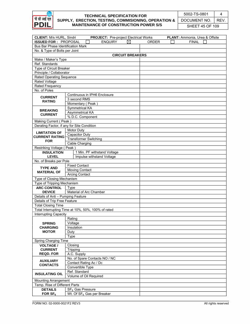
TECHNICAL SPECIFICATION FOR SUPPLY, ERECTION, TESTING, COMMISIONING, OPERATION &
MAINTENANCE OF CONSTRUCTION POWER S/S
5002-TS-0801 4 DOCUMENT NO. REV.
SHEET 45 OF 109
FORM NO: 02-0000-0021F2 REV3 All rights reserved
CLIENT: M/s HURL, Sindri PROJECT: Pre-project Electrical Works PLANT: Ammonia, Urea & Offsite ISSUED FOR : PROPOSAL ENQUIRY ORDER FINAL Bus Bar Phase Identification Mark No. & Type of Bolts per Joint
CIRCUIT BREAKERS Make / Maker’s Type Ref. Standards Type of Circuit Breaker Principle / Collaborator Rated Operating Sequence Rated Voltage Rated Frequency No. of Poles
CURRENT RATING
Continuous in IPH6 Enclosure 3 second RMS Momentary ( Peak )
BREAKING CURRENT
Symmetrical KA Asymmetrical KA % D.C. Component
Making Current ( Peak ) Derating Factor, if any for Site Condition
LIMITATION OF CURRENT RATING
FOR
Motor Duty Capacitor Duty Transformer Switching Cable Charging
Restriking Voltage ( Peak ) INSULATION
LEVEL 1 Min. PF withstand Voltage Impulse withstand Voltage
No. of Breaks per Pole
TYPE AND MATERIAL OF
Fixed Contact Moving Contact Arcing Contact
Type of Closing Mechanism Type of Tripping Mechanism ARC CONTROL
DEVICE Type Material of Arc Chamber
Details of Anti – Pumping Feature Details of Trip Free Feature Total Closing Time Total Interrupting Time at 10%, 50%, 100% of rated Interrupting Capacity
SPRING CHARGING
MOTOR
Rating Voltage Insulation Duty Type
Spring Charging Time VOLTAGE / CURRENT
REQD. FOR
Closing Tripping A.C. Supply
AUXILIARY CONTACTS
No. of Spare Contacts NO / NC Contact Rating Ac / Dc Convertible Type
INSULATING OIL Ref. Standard Volume of Oil Required
Mounting Arrangement Temp. Rise of Different Parts
DETAILS FOR SF6
SF6 Gas Pressure Wt. Of SF6 Gas per Breaker

TECHNICAL SPECIFICATION FOR SUPPLY, ERECTION, TESTING, COMMISIONING, OPERATION &
MAINTENANCE OF CONSTRUCTION POWER S/S
5002-TS-0801 4 DOCUMENT NO. REV.
SHEET 46 OF 109
FORM NO: 02-0000-0021F2 REV3 All rights reserved
CLIENT: M/s HURL, Sindri PROJECT: Pre-project Electrical Works PLANT: Ammonia, Urea & Offsite ISSUED FOR : PROPOSAL ENQUIRY ORDER FINAL
DETAILS FOR SF6
Gas Leakage Detector Provided Gas Density Monitor Provided
DETAILS FOR VCB
Pressure inside the Interrupter Contact Wear Indication Provided Facility for Checking Loss of Vacuum Provided
RECOMMENDED TIME INTERVAL
FOR
Inspection of Drives Inspection of Contacts Quenching Devices Replacement of Oil
Dimensions : L X B X H / Dim. Drg. Ref. No. Type Testing Authority & Test Report Ref. No. Net Weight of Breaker
CURRENT TRANSFORMERS Make / Maker’s Type Ref. Standard Type of Primary Winding No. of Cores Ratio Rated Burden Accuracy Class ALF / ISF Thermal Limit Dynamic Limit Insulation Class / Material Basic Insulation Level Ref. Magnetisation Curve No.
POTENTIAL TRANSFORMERS Make / Maker’s Type Ref. Standard Winding Connection : Pri. / Sec. Ratio Rated Burden Accuracy Class Insulation Class / Material Basic Insulation Level Weight Dimension Rated Voltage Factor
SURGE DIVERTER Type & Maker’s Type Rated Voltage KV Nominal Discharge Current ( 8/20 µ sec. wave ) Residual Voltage at Rated Discharge Current Power Frequency Spark Over Voltage 1.2/50 µ sec. Spark Over Voltage
RELAYS Application Make / Maker’s Type : Ref. Standards Operating Principle Rated Voltage / Current Rated Burden Setting Range Type of Mounting Reset : Hand or Self Flag Indication Type Ref. Characteristic Curve Type

TECHNICAL SPECIFICATION FOR SUPPLY, ERECTION, TESTING, COMMISIONING, OPERATION &
MAINTENANCE OF CONSTRUCTION POWER S/S
5002-TS-0801 4 DOCUMENT NO. REV.
SHEET 47 OF 109
FORM NO: 02-0000-0021F2 REV3 All rights reserved
CLIENT: M/s HURL, Sindri PROJECT: Pre-project Electrical Works PLANT: Ammonia, Urea & Offsite ISSUED FOR : PROPOSAL ENQUIRY ORDER FINAL Ref. Descriptive catalogue
INSTRUMENTS AND METERS Application Make / Maker’s Type : Ref. Standards Operating Principle Rated Burden Scale Range Accuracy Size Type of Mounting
CONTROL SWITCHES Application Make / Maker’s Type : Ref. Standards Contact Rating Utilisation Category
PUSH BUTTON Make / Maker’s Type : Ref. Standards Contact Rating Utilisation Category
SIGNAL LAMPS Make / Maker’s Type : Ref. Standards Rated Voltage / Wattage Type of Lamp Holder Type of Globe Accessibility from Front
MOULDED CASE CIRCUIT BREAKERS Make / Maker’s Type Ref. Standard Current Rating Breaking Capacity Setting Range of Thermal Release Setting Range of Magnetic Release
MINIATURE CIRCUIT BREAKER Make / Maker’s Type : Ref. Standards Rated Current Breaking Capacity
CABLE GLANDS Material Type
TERMINAL BLOCKS Make Type Current Rating
NOTE: Completely filled in Technical Particulars Sheet shall be furnished along with the bid and for owner/consultant approval before commencement of manufacturing in line with NIT/PO.

TECHNICAL SPECIFICATION FOR SUPPLY, ERECTION, TESTING, COMMISIONING, OPERATION &
MAINTENANCE OF CONSTRUCTION POWER S/S
5002-TS-0801 4 DOCUMENT NO. REV.
SHEET 48 OF 109
FORM NO: 02-0000-0021F2 REV3 All rights reserved
SPECIFICATION SHEET TRANSFORMERS
CLIENT: M/s HURL, Sindri PROJECT: Pre-project Electrical Works PLANT: Ammonia, Urea & Offsite ISSUED FOR : PROPOSAL ENQUIRY ORDER FINAL GENERAL Item No. : Ref. Stds. : IS-2026, IEC-60076 Quantity : 1 No. Encl. Docs. : Description : Power Transformers Vendor : Code No. : Vendor’s Ref. No. : TEST TO BE WITNESSED : Routine : Heat Run : Impulse : Others :
SERVICE CONDITIONS SYSTEM DETAILS (PRI. / SEC.) AMBIENT CONDITIONS
Nom. Voltage with ± % : 33KV±10% / 3.45KV±10% Temp.- Max./Min./Design Ref. : 47.7 / 2.3 / 50°C Highest System Voltage : 36 KV / 3.6 kV Rel. Humidity : 100% Alt. above Sea < 1000M Number of phases : 3 Ph / 3 W Atmospheric
Pollution Dusts : Urea
Rated Frequency with + : 50 Hz ± 5% Vapour : Ammonia Combined V & F Variation : ± 10 % Location Indoor : Outdoor : Fault MVA : 21 KA / 26.24 KA AUX. POWER SUPPLY Earthing Mode : Earthed through NER System
Data A.C. : 415V ± 10%, 3P & N, 50Hz ± 5%
D.C. : 220V Instrument
Contact Rating A.C. : 240V, 5 Amps
D.C. : 220V, 5 Amps BASIC DATA
RATING TERMINAL CONFIGURATION Rated Capacity : 3 MVA W No Load Voltage Ratio : 33 KV / 3.43 KV X Z Highest Voltage for Eqpt. : 36 KV / 3.6 KV Y Insulation level Pri. / Sec
Impulse : 170 KV / 40 KV Shall be provided later. Power Freq. : 70 KV / 10 KV TERMINAL CONNECTIONS
Impedance at 75°C: 6.25% (without negative tolerance as per IS)
PRI.
Arrangement
O/H bushing :
Vector Group : Dyn 11 Bus Duct : Cooling System : ONAN Cable : Motor I Start & T Start :
Cable cond. Type : 33 KV XLPE-A-FRLS-PVC (Al) UE
TAP CHANGER No. & Size : 1-3CX300 sq. mm (Al) Type of Taps On Load : Off Ckt. :
SEC.
Arrangement O/H bushing :
Range of Taps : -5% TO +5% Bus Duct : No. of Taps : 5 @ 2.5 % Cable :
C.T. REQUIREMENTS Cable cond.
Type : 3.3 KV XLPE-A-FRLS-PVC (Al) UE
Differential Protection
3 nos. on Trf. : No. & Size: 3-3CX300 sq. mm (Al) 3 nos. Loose : Control Cable Type : 1.1 KV XLPE-A-FRLS PVC (ST2)
(Cu) Restricted earth fault Protection
1 no. on Trf: Cl.-PS* No. & Size : 19X2.5 mm2, 2CX10 mm2, 5X2.5 mm2
3 nos. Loose : Cl.-PS Earth Conductor Body : 2-75X10 GI strip Standby earth fault Protection
1 no. on Trf. : Cl.-5P10 Neutral : 2-1CX185 mm2 XLPE-UA-FRLS PVC (Al), 3.3 KV (E)
Cable Gland
Type & Material
Primary : Double ADDITIONAL FITTINGS Secondary : compression
1. LV Neutral terminal box Control : Rolled Al 2. Thermometer pocket with cover PAINTING 3. Tank magnetic oil level gauge Type : EPOXY BASED 4. Bi-directional roller Shade : 631 OF IS : 5 SPARE PARTS Reqd. : For a period of 2 Years
- All unfilled data shall be filled and duly stamped & signed by the bidder. - * REF CT shall be supplied loose by the owner. However, mounting arrangement for REF CT shall be provided by the
bidder. - Impulse test certificate for similar rating shall be furnished with offer by bidder.
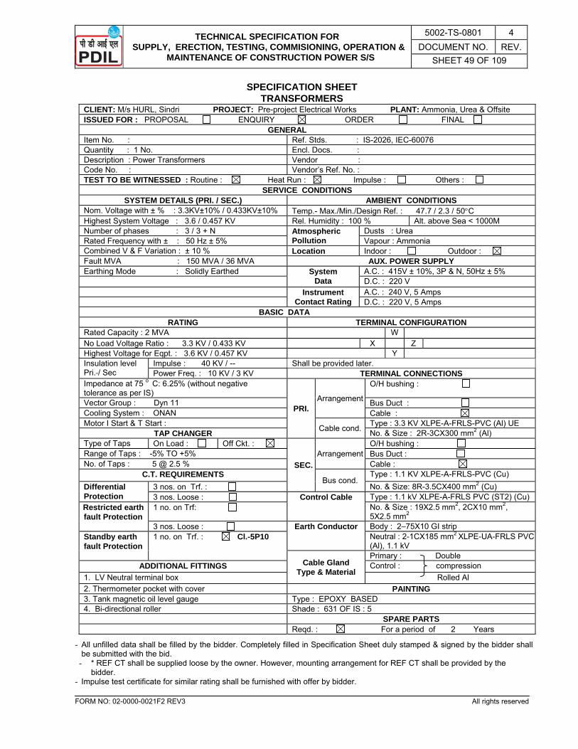
TECHNICAL SPECIFICATION FOR SUPPLY, ERECTION, TESTING, COMMISIONING, OPERATION &
MAINTENANCE OF CONSTRUCTION POWER S/S
5002-TS-0801 4 DOCUMENT NO. REV.
SHEET 49 OF 109
FORM NO: 02-0000-0021F2 REV3 All rights reserved
SPECIFICATION SHEET TRANSFORMERS
CLIENT: M/s HURL, Sindri PROJECT: Pre-project Electrical Works PLANT: Ammonia, Urea & Offsite ISSUED FOR : PROPOSAL ENQUIRY ORDER FINAL GENERAL Item No. : Ref. Stds. : IS-2026, IEC-60076 Quantity : 1 No. Encl. Docs. : Description : Power Transformers Vendor : Code No. : Vendor’s Ref. No. : TEST TO BE WITNESSED : Routine : Heat Run : Impulse : Others :
SERVICE CONDITIONS SYSTEM DETAILS (PRI. / SEC.) AMBIENT CONDITIONS
Nom. Voltage with ± % : 3.3KV±10% / 0.433KV±10% Temp.- Max./Min./Design Ref. : 47.7 / 2.3 / 50°C Highest System Voltage : 3.6 / 0.457 KV Rel. Humidity : 100 % Alt. above Sea < 1000M Number of phases : 3 / 3 + N Atmospheric
Pollution Dusts : Urea
Rated Frequency with ± : 50 Hz ± 5% Vapour : Ammonia Combined V & F Variation : ± 10 % Location Indoor : Outdoor : Fault MVA : 150 MVA / 36 MVA AUX. POWER SUPPLY Earthing Mode : Solidly Earthed System
Data A.C. : 415V ± 10%, 3P & N, 50Hz ± 5%
D.C. : 220 V Instrument
Contact Rating A.C. : 240 V, 5 Amps
D.C. : 220 V, 5 Amps BASIC DATA
RATING TERMINAL CONFIGURATION Rated Capacity : 2 MVA W No Load Voltage Ratio : 3.3 KV / 0.433 KV X Z Highest Voltage for Eqpt. : 3.6 KV / 0.457 KV Y Insulation level Pri. / Sec
Impulse : 40 KV / -- Shall be provided later. Power Freq. : 10 KV / 3 KV TERMINAL CONNECTIONS
Impedance at 75 o C: 6.25% (without negative tolerance as per IS)
PRI. Arrangement
O/H bushing :
Vector Group : Dyn 11 Bus Duct : Cooling System : ONAN Cable : Motor I Start & T Start : Cable cond. Type : 3.3 KV XLPE-A-FRLS-PVC (Al) UE
TAP CHANGER No. & Size : 2R-3CX300 mm2 (Al) Type of Taps On Load : Off Ckt. :
SEC.Arrangement
O/H bushing : Range of Taps : -5% TO +5% Bus Duct : No. of Taps : 5 @ 2.5 % Cable :
C.T. REQUIREMENTS Bus cond.
Type : 1.1 KV XLPE-A-FRLS-PVC (Cu) Differential Protection
3 nos. on Trf. : No. & Size: 8R-3.5CX400 mm2 (Cu) 3 nos. Loose : Control Cable Type : 1.1 kV XLPE-A-FRLS PVC (ST2) (Cu)
Restricted earth fault Protection
1 no. on Trf: No. & Size : 19X2.5 mm2, 2CX10 mm2, 5X2.5 mm2
3 nos. Loose : Earth Conductor Body : 2–75X10 GI strip Standby earth fault Protection
1 no. on Trf. : Cl.-5P10 Neutral : 2-1CX185 mm2 XLPE-UA-FRLS PVC (Al), 1.1 kV
Cable Gland Type & Material
Primary : Double ADDITIONAL FITTINGS Control : compression
1. LV Neutral terminal box Rolled Al 2. Thermometer pocket with cover PAINTING 3. Tank magnetic oil level gauge Type : EPOXY BASED 4. Bi-directional roller Shade : 631 OF IS : 5 SPARE PARTS Reqd. : For a period of 2 Years
- All unfilled data shall be filled by the bidder. Completely filled in Specification Sheet duly stamped & signed by the bidder shall be submitted with the bid.
- * REF CT shall be supplied loose by the owner. However, mounting arrangement for REF CT shall be provided by the bidder.
- Impulse test certificate for similar rating shall be furnished with offer by bidder.
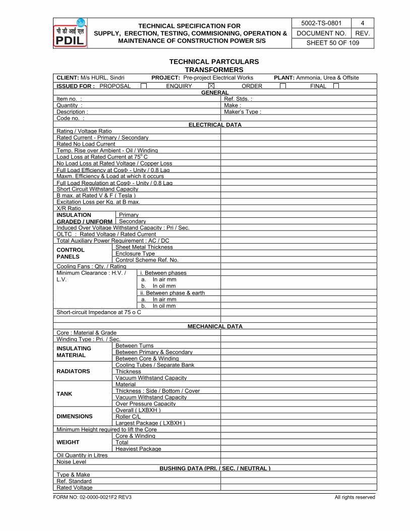
TECHNICAL SPECIFICATION FOR SUPPLY, ERECTION, TESTING, COMMISIONING, OPERATION &
MAINTENANCE OF CONSTRUCTION POWER S/S
5002-TS-0801 4 DOCUMENT NO. REV.
SHEET 50 OF 109
FORM NO: 02-0000-0021F2 REV3 All rights reserved
TECHNICAL PARTCULARS TRANSFORMERS
CLIENT: M/s HURL, Sindri PROJECT: Pre-project Electrical Works PLANT: Ammonia, Urea & Offsite ISSUED FOR : PROPOSAL ENQUIRY ORDER FINAL
GENERALItem no. : Ref. Stds. :Quantity : Make :Description : Maker’s Type :Code no. :
ELECTRICAL DATARating / Voltage Ratio Rated Current - Primary / Secondary Rated No Load Current Temp. Rise over Ambient - Oil / Winding Load Loss at Rated Current at 75o C No Load Loss at Rated Voltage / Copper LossFull Load Efficiency at CosΦ - Unity / 0.8 LagMaxm. Efficiency & Load at which it occurs Full Load Regulation at CosΦ - Unity / 0.8 LagShort Circuit Withstand Capacity B max. at Rated V & F ( Tesla ) Excitation Loss per Kg. at B max. X/R Ratio INSULATION GRADED / UNIFORM
Primary Secondary
Induced Over Voltage Withstand Capacity : Pri / Sec.OLTC : Rated Voltage / Rated Current Total Auxiliary Power Requirement : AC / DCCONTROL PANELS
Sheet Metal ThicknessEnclosure Type Control Scheme Ref. No.
Cooling Fans : Qty. / Rating Minimum Clearance : H.V. / L.V.
i. Between phasesa. In air mm b. In oil mm
ii. Between phase & earth a. In air mmb. In oil mm
Short-circuit Impedance at 75 o C
MECHANICAL DATACore : Material & Grade Winding Type : Pri. / Sec. INSULATING MATERIAL
Between Turns Between Primary & SecondaryBetween Core & Winding
RADIATORS Cooling Tubes / Separate BankThickness Vacuum Withstand Capacity
TANK Material Thickness : Side / Bottom / CoverVacuum Withstand CapacityOver Pressure Capacity
DIMENSIONS Overall ( LXBXH ) Roller C/L Largest Package ( LXBXH )
Minimum Height required to lift the Core
WEIGHT Core & Winding Total Heaviest Package
Oil Quantity in Litres Noise Level
BUSHING DATA (PRI. / SEC. / NEUTRAL )Type & Make Ref. Standard Rated Voltage
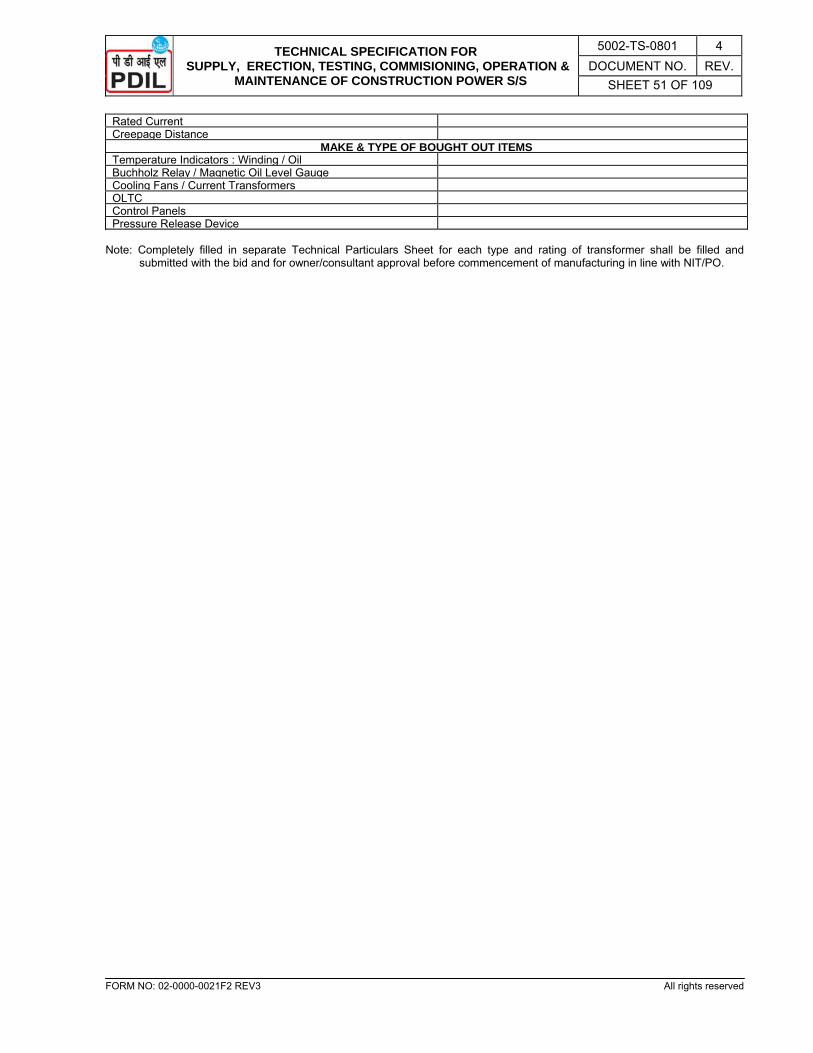
TECHNICAL SPECIFICATION FOR SUPPLY, ERECTION, TESTING, COMMISIONING, OPERATION &
MAINTENANCE OF CONSTRUCTION POWER S/S
5002-TS-0801 4 DOCUMENT NO. REV.
SHEET 51 OF 109
FORM NO: 02-0000-0021F2 REV3 All rights reserved
Rated Current Creepage Distance
MAKE & TYPE OF BOUGHT OUT ITEMSTemperature Indicators : Winding / Oil Buchholz Relay / Magnetic Oil Level GaugeCooling Fans / Current Transformers OLTC Control Panels Pressure Release Device
Note: Completely filled in separate Technical Particulars Sheet for each type and rating of transformer shall be filled and
submitted with the bid and for owner/consultant approval before commencement of manufacturing in line with NIT/PO.
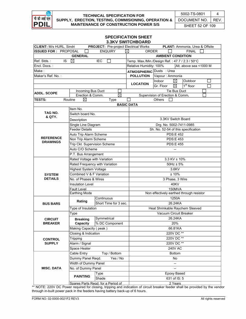
TECHNICAL SPECIFICATION FOR SUPPLY, ERECTION, TESTING, COMMISIONING, OPERATION &
MAINTENANCE OF CONSTRUCTION POWER S/S
5002-TS-0801 4 DOCUMENT NO. REV.
SHEET 52 OF 109
FORM NO: 02-0000-0021F2 REV3 All rights reserved
SPECIFICATION SHEET 3.3KV SWITCHBOARD
CLIENT: M/s HURL, Sindri PROJECT: Pre-project Electrical Works PLANT: Ammonia, Urea & Offsite ISSUED FOR : PROPOSAL ENQUIRY ORDER FINAL
GENERAL AMBIENT CONDITION Ref. Stds. : IS IEC Temp. Max./Min./Design Ref. : 47.7 / 2.3 / 50°C Encl. Docs. : Relative Humidity: 100% Alt. above sea <1000 M Make : ATMOSPHERIC
POLLUTION Dusts : Urea
Maker’s Ref. No. : Vapour : Ammonia
LOCATION Indoor Outdoor
Gr. Floor 1st floor
ADDL. SCOPE Incoming Bus Duct Tie Bus Duct Erection & Comm. Supervision of Erection & Comm.
TESTS: Routine Type Others BASIC DATA
TAG NO. & QTY.
Item No. Switch board No.
Description 3.3KV Switch Board
REFERENCE DRAWINGS
Single Line Diagram Drg. No. 5002-7411-0985 Feeder Details Sh. No. 52-54 of this specification Auto Trip Alarm Scheme PDS:E 452 Non Trip Alarm Scheme PDS:E 453 Trip Ckt. Supervision Scheme PDS:E 455 Auto C/O Scheme -- P.T. Bus Arrangement
SYSTEM DETAILS
Rated Voltage with Variation 3.3 KV ± 10% Rated Frequency with Variation 50Hz ± 5% Highest System Voltage 3.6KV Combined V & F Variation ± 10% No. of Phases & Wires 3 Phase, 3 Wire Insulation Level 40KV Fault Level 150MVA Earthing Mode Non effectively earthed through resistor
BUS BARS Rating
Continuous 1250A Short Time for 3 sec. 26.24KA
Type of Insulation Heat Shrinkable Raychem Sleeved
CIRCUIT BREAKER
Type Vacuum Circuit Breaker
Breaking Capacity
Symmetrical 26.24KA % DC Component 20%
Making Capacity ( peak ) 66.81KA
CONTROL SUPPLY
Closing & Indication 220V DC ** Tripping 220V DC ** Alarm / Signal 220V DC ** Space Heater 240V AC
MISC. DATA
Cable Entry Top / Bottom Bottom Dummy Panel Reqd. Yes / No No Width of Dummy Panel -- No. of Dummy Panel --
PAINTING Type Epoxy Based Shade 631 of IS: 5
Spares Parts Reqd. for a Period of 2 Years ** NOTE: 220V DC Power required for closing, tripping and indication of circuit breaker feeder shall be provided by the vendor through in-built power pack in the feeders having battery back-up of 6 hours.
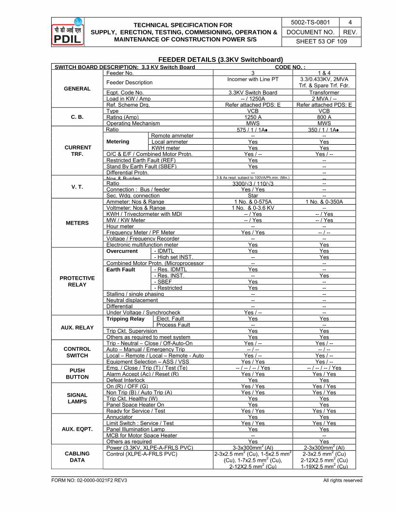
TECHNICAL SPECIFICATION FOR SUPPLY, ERECTION, TESTING, COMMISIONING, OPERATION &
MAINTENANCE OF CONSTRUCTION POWER S/S
5002-TS-0801 4 DOCUMENT NO. REV.
SHEET 53 OF 109
FORM NO: 02-0000-0021F2 REV3 All rights reserved
FEEDER DETAILS (3.3KV Switchboard) SWITCH BOARD DESCRIPTION: 3.3 KV Switch Board CODE NO. :
GENERAL
Feeder No. 3 1 & 4
Feeder Description Incomer with Line PT 3.3/0.433KV, 2MVA Trf. & Spare Trf. Fdr.
Eqpt. Code No. 3.3KV Switch Board TransformerLoad in KW / Amp -- / 1250A 2 MVA / --Ref. Scheme Drg. Refer attached PDS: E Refer attached PDS: E
C. B. Type VCB VCBRating (Amp) 1250 A 800 AOperating Mechanism MWS MWS
CURRENT TRF.
Ratio 575 / 1 / 1A♦ 350 / 1 / 1A♦
Metering Remote ammeter -- --Local ammeter Yes YesKWH meter Yes Yes
O/C & E/F / Combined Motor Protn. Yes / -- Yes / --Restricted Earth Fault (REF) Yes --Stand By Earth Fault (SBEF) Yes --Differential Protn. -- --
V. T. Nos & Burden 3 & As reqd. subject to 100VA/Ph.min. (Min.) --Ratio 3300/√3 / 110/√3 --Connection : Bus / feeder Yes / Yes --Sec. Wdg. connection Star --
METERS
Ammeter: Nos & Range 1 No. & 0-575A 1 No. & 0-350AVoltmeter: Nos & Range 1 No. & 0-3.6 KV --KWH / Trivectormeter with MDI -- / Yes -- / YesMW / KW Meter -- / Yes -- / YesHour meter -- --Frequency Meter / PF Meter Yes / Yes -- / --Voltage / Frequency Recorder -- --Electronic multifunction meter Yes Yes
PROTECTIVE RELAY
Overcurrent - IDMTL Yes Yes- High set INST. -- Yes
Combined Motor Protn. (Microprocessor -- --Earth Fault - Res. IDMTL Yes --
- Res. INST. -- Yes- SBEF Yes --- Restricted Yes --
Stalling / single phasing -- --Neutral displacement -- --Differential -- --Under Voltage / Synchrocheck Yes / -- --
AUX. RELAY Tripping Relay Elect. Fault Yes Yes
Process Fault -- --Trip Ckt. Supervision Yes YesOthers as required to meet system Yes Yes
CONTROL SWITCH
Trip - Neutral – Close / Off-Auto-On Yes / -- Yes / --Auto – Manual / Emergency Trip -- / -- -- / --Local – Remote / Local – Remote - Auto Yes / -- Yes / --Equipment Selection – ASS / VSS Yes / Yes Yes / --
PUSH BUTTON
Emg. / Close / Trip (T) / Test (Te) -- / -- / -- / Yes -- / -- / -- / YesAlarm Accept (Ac) / Reset (R) Yes / Yes Yes / YesDefeat Interlock Yes Yes
SIGNAL LAMPS
On (R) / OFF (G) Yes / Yes Yes / YesNon Trip (B) / Auto Trip (A) Yes / Yes Yes / YesTrip Ckt. Healthy (W) Yes YesPanel Space Heater On Yes YesReady for Service / Test Yes / Yes Yes / Yes
AUX. EQPT.
Annuciator Yes YesLimit Switch : Service / Test Yes / Yes Yes / YesPanel Illumination Lamp Yes YesMCB for Motor Space Heater -- --Others as required Yes Yes
CABLING DATA
Power (3.3KV, XLPE-A-FRLS PVC) 3-3x300mm2 (Al) 2-3x300mm2 (Al)Control (XLPE-A-FRLS PVC) 2-3x2.5 mm2 (Cu), 1-5x2.5 mm2
(Cu), 1-7x2.5 mm2 (Cu), 2-12X2.5 mm2 (Cu)
2-3x2.5 mm2 (Cu) 2-12X2.5 mm2 (Cu) 1-19X2.5 mm2 (Cu)
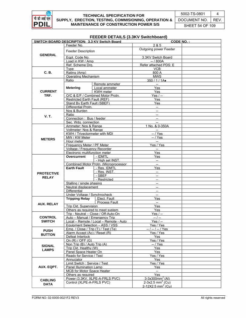
TECHNICAL SPECIFICATION FOR SUPPLY, ERECTION, TESTING, COMMISIONING, OPERATION &
MAINTENANCE OF CONSTRUCTION POWER S/S
5002-TS-0801 4 DOCUMENT NO. REV.
SHEET 54 OF 109
FORM NO: 02-0000-0021F2 REV3 All rights reserved
FEEDER DETAILS (3.3KV Switchboard) SWITCH BOARD DESCRIPTION: 3.3 KV Switch Board CODE NO. :
GENERAL
Feeder No. 2 & 5
Feeder Description Outgoing power Feeder
Eqpt. Code No. 3.3KV Switch BoardLoad in KW / Amp -- / 800ARef. Scheme Drg. Refer attached PDS: E
C. B. Type VCBRating (Amp) 800 AOperating Mechanism MWS
CURRENT TRF.
Ratio 350 / 1 / 1A♦
Metering Remote ammeter --Local ammeter YesKWH meter Yes
O/C & E/F / Combined Motor Protn. Yes / --Restricted Earth Fault (REF) YesStand By Earth Fault (SBEF) YesDifferential Protn. --
V. T. Nos & Burden --Ratio --Connection : Bus / feeder --Sec. Wdg. connection --
METERS
Ammeter: Nos & Range 1 No. & 0-350AVoltmeter: Nos & Range --KWH / Trivectormeter with MDI -- / YesMW / KW Meter -- / YesHour meter --Frequency Meter / PF Meter Yes / YesVoltage / Frequency Recorder --Electronic multifunction meter Yes
PROTECTIVE RELAY
Overcurrent - IDMTL Yes- High set INST. --
Combined Motor Protn. (Microprocessor --Earth Fault - Res. IDMTL Yes
- Res. INST. --- SBEF --- Restricted --
Stalling / single phasing --Neutral displacement --Differential --Under Voltage / Synchrocheck --
AUX. RELAY Tripping Relay Elect. Fault Yes
Process Fault --Trip Ckt. Supervision YesOthers as required to meet system Yes
CONTROL SWITCH
Trip - Neutral – Close / Off-Auto-On Yes / --Auto – Manual / Emergency Trip -- / --Local – Remote / Local – Remote - Auto Yes / --Equipment Selection – ASS / VSS Yes / Yes
PUSH BUTTON
Emg. / Close / Trip (T) / Test (Te) -- / -- / -- / YesAlarm Accept (Ac) / Reset (R) Yes / YesDefeat Interlock Yes
SIGNAL LAMPS
On (R) / OFF (G) Yes / YesNon Trip (B) / Auto Trip (A) -- / YesTrip Ckt. Healthy (W) YesPanel Space Heater On YesReady for Service / Test Yes / Yes
AUX. EQPT.
Annuciator YesLimit Switch : Service / Test Yes / YesPanel Illumination Lamp YesMCB for Motor Space Heater --Others as required Yes
CABLING DATA
Power (3.3KV, XLPE-A-FRLS PVC) 3-3x300mm2 (Al)Control (XLPE-A-FRLS PVC) 2-3x2.5 mm2 (Cu)
2-12X2.5 mm2 (Cu)
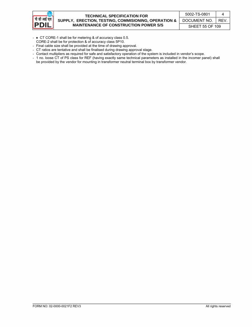
TECHNICAL SPECIFICATION FOR SUPPLY, ERECTION, TESTING, COMMISIONING, OPERATION &
MAINTENANCE OF CONSTRUCTION POWER S/S
5002-TS-0801 4 DOCUMENT NO. REV.
SHEET 55 OF 109
FORM NO: 02-0000-0021F2 REV3 All rights reserved
- ♦ CT CORE-1 shall be for metering & of accuracy class 0.5. CORE-2 shall be for protection & of accuracy class 5P10.
- Final cable size shall be provided at the time of drawing approval. - CT ratios are tentative and shall be finalised during drawing approval stage. - Contact multipliers as required for safe and satisfactory operation of the system is included in vendor’s scope. - 1 no. loose CT of PS class for REF (having exactly same technical parameters as installed in the incomer panel) shall
be provided by the vendor for mounting in transformer neutral terminal box by transformer vendor.
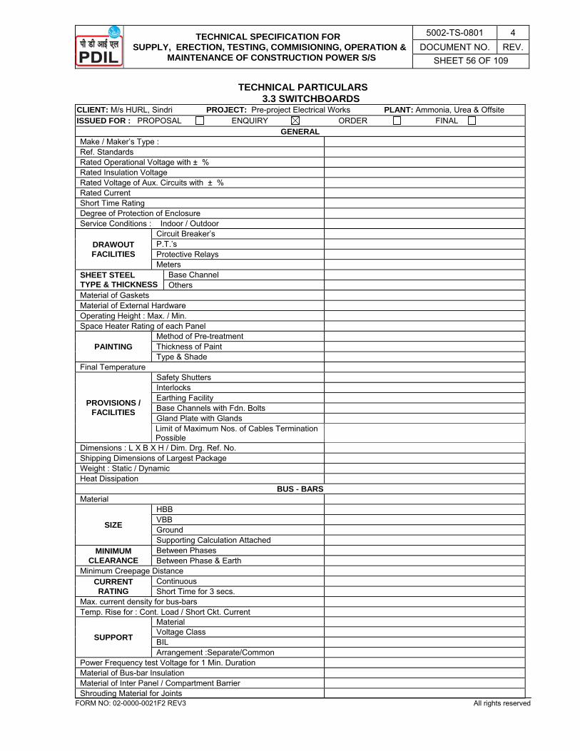
TECHNICAL SPECIFICATION FOR SUPPLY, ERECTION, TESTING, COMMISIONING, OPERATION &
MAINTENANCE OF CONSTRUCTION POWER S/S
5002-TS-0801 4 DOCUMENT NO. REV.
SHEET 56 OF 109
FORM NO: 02-0000-0021F2 REV3 All rights reserved
TECHNICAL PARTICULARS 3.3 SWITCHBOARDS
CLIENT: M/s HURL, Sindri PROJECT: Pre-project Electrical Works PLANT: Ammonia, Urea & Offsite ISSUED FOR : PROPOSAL ENQUIRY ORDER FINAL
GENERAL Make / Maker’s Type : Ref. Standards Rated Operational Voltage with ± % Rated Insulation Voltage Rated Voltage of Aux. Circuits with ± % Rated Current Short Time Rating Degree of Protection of Enclosure Service Conditions : Indoor / Outdoor
DRAWOUT FACILITIES
Circuit Breaker’s P.T.’s Protective Relays Meters
SHEET STEEL TYPE & THICKNESS
Base Channel Others
Material of Gaskets Material of External Hardware Operating Height : Max. / Min. Space Heater Rating of each Panel
PAINTING Method of Pre-treatment Thickness of Paint Type & Shade
Final Temperature
PROVISIONS / FACILITIES
Safety Shutters Interlocks Earthing Facility Base Channels with Fdn. Bolts Gland Plate with Glands Limit of Maximum Nos. of Cables Termination Possible
Dimensions : L X B X H / Dim. Drg. Ref. No. Shipping Dimensions of Largest Package Weight : Static / Dynamic Heat Dissipation
BUS - BARS Material
SIZE
HBB VBB Ground Supporting Calculation Attached
MINIMUM CLEARANCE
Between Phases Between Phase & Earth
Minimum Creepage Distance CURRENT RATING
Continuous Short Time for 3 secs.
Max. current density for bus-bars Temp. Rise for : Cont. Load / Short Ckt. Current
SUPPORT
Material Voltage Class BIL Arrangement :Separate/Common
Power Frequency test Voltage for 1 Min. Duration Material of Bus-bar Insulation Material of Inter Panel / Compartment Barrier Shrouding Material for Joints

TECHNICAL SPECIFICATION FOR SUPPLY, ERECTION, TESTING, COMMISIONING, OPERATION &
MAINTENANCE OF CONSTRUCTION POWER S/S
5002-TS-0801 4 DOCUMENT NO. REV.
SHEET 57 OF 109
FORM NO: 02-0000-0021F2 REV3 All rights reserved
CLIENT: M/s HURL, Sindri PROJECT: Pre-project Electrical Works PLANT: Ammonia, Urea & Offsite ISSUED FOR : PROPOSAL ENQUIRY ORDER FINAL Bus Bar Phase Identification Mark No. & Type of Bolts per Joint
CIRCUIT BREAKERS Make / Maker’s Type Ref. Standards Type of Circuit Breaker Principle / Collaborator Rated Operating Sequence Rated Voltage Rated Frequency No. of Poles
CURRENT RATING
Continuous in IPH6 Enclosure 3 second RMS Momentary ( Peak )
BREAKING CURRENT
Symmetrical KA Asymmetrical KA % D.C. Component
Making Current ( Peak ) Derating Factor, if any for Site Condition
LIMITATION OF CURRENT RATING
FOR
Motor Duty Capacitor Duty Transformer Switching Cable Charging
Restriking Voltage ( Peak ) INSULATION
LEVEL 1 Min. PF withstand Voltage Impulse withstand Voltage
No. of Breaks per Pole
TYPE AND MATERIAL OF
Fixed Contact Moving Contact Arcing Contact
Type of Closing Mechanism Type of Tripping Mechanism ARC CONTROL
DEVICE Type Material of Arc Chamber
Details of Anti – Pumping Feature Details of Trip Free Feature Total Closing Time Total Interrupting Time at 10%, 50%, 100% of rated Interrupting Capacity
SPRING CHARGING
MOTOR
Rating Voltage Insulation Duty Type
Spring Charging Time VOLTAGE / CURRENT
REQD. FOR
Closing Tripping A.C. Supply
AUXILIARY CONTACTS
No. of Spare Contacts NO / NC Contact Rating Ac / Dc Convertible Type
INSULATING OIL Ref. Standard Volume of Oil Required
Mounting Arrangement Temp. Rise of Different Parts
DETAILS FOR SF6
SF6 Gas Pressure Wt. Of SF6 Gas per Breaker
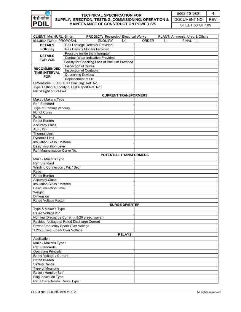
TECHNICAL SPECIFICATION FOR SUPPLY, ERECTION, TESTING, COMMISIONING, OPERATION &
MAINTENANCE OF CONSTRUCTION POWER S/S
5002-TS-0801 4 DOCUMENT NO. REV.
SHEET 58 OF 109
FORM NO: 02-0000-0021F2 REV3 All rights reserved
CLIENT: M/s HURL, Sindri PROJECT: Pre-project Electrical Works PLANT: Ammonia, Urea & Offsite ISSUED FOR : PROPOSAL ENQUIRY ORDER FINAL
DETAILS FOR SF6
Gas Leakage Detector Provided Gas Density Monitor Provided
DETAILS FOR VCB
Pressure inside the Interrupter Contact Wear Indication Provided Facility for Checking Loss of Vacuum Provided
RECOMMENDED TIME INTERVAL
FOR
Inspection of Drives Inspection of Contacts Quenching Devices Replacement of Oil
Dimensions : L X B X H / Dim. Drg. Ref. No. Type Testing Authority & Test Report Ref. No. Net Weight of Breaker
CURRENT TRANSFORMERS Make / Maker’s Type Ref. Standard Type of Primary Winding No. of Cores Ratio Rated Burden Accuracy Class ALF / ISF Thermal Limit Dynamic Limit Insulation Class / Material Basic Insulation Level Ref. Magnetisation Curve No.
POTENTIAL TRANSFORMERS Make / Maker’s Type Ref. Standard Winding Connection : Pri. / Sec. Ratio Rated Burden Accuracy Class Insulation Class / Material Basic Insulation Level Weight Dimension Rated Voltage Factor
SURGE DIVERTER Type & Maker’s Type Rated Voltage KV Nominal Discharge Current ( 8/20 µ sec. wave ) Residual Voltage at Rated Discharge Current Power Frequency Spark Over Voltage 1.2/50 µ sec. Spark Over Voltage
RELAYS Application Make / Maker’s Type : Ref. Standards Operating Principle Rated Voltage / Current Rated Burden Setting Range Type of Mounting Reset : Hand or Self Flag Indication Type Ref. Characteristic Curve Type
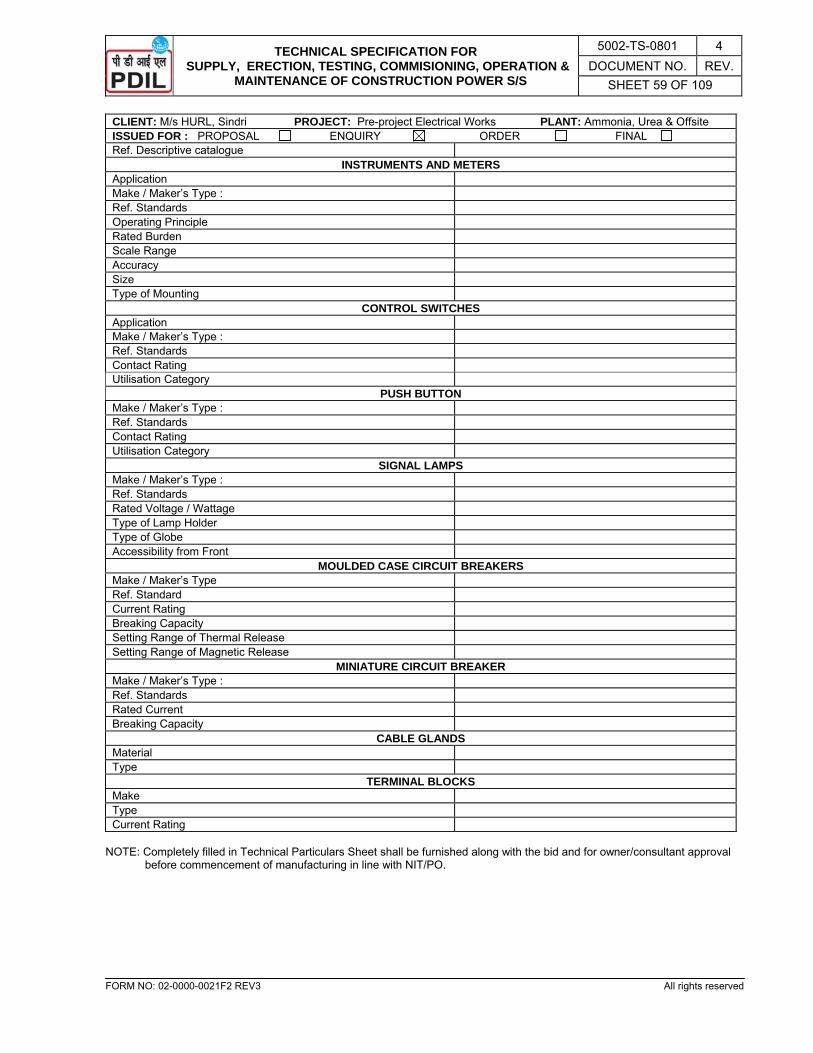
TECHNICAL SPECIFICATION FOR SUPPLY, ERECTION, TESTING, COMMISIONING, OPERATION &
MAINTENANCE OF CONSTRUCTION POWER S/S
5002-TS-0801 4 DOCUMENT NO. REV.
SHEET 59 OF 109
FORM NO: 02-0000-0021F2 REV3 All rights reserved
CLIENT: M/s HURL, Sindri PROJECT: Pre-project Electrical Works PLANT: Ammonia, Urea & Offsite ISSUED FOR : PROPOSAL ENQUIRY ORDER FINAL Ref. Descriptive catalogue
INSTRUMENTS AND METERS Application Make / Maker’s Type : Ref. Standards Operating Principle Rated Burden Scale Range Accuracy Size Type of Mounting
CONTROL SWITCHES Application Make / Maker’s Type : Ref. Standards Contact Rating Utilisation Category
PUSH BUTTON Make / Maker’s Type : Ref. Standards Contact Rating Utilisation Category
SIGNAL LAMPS Make / Maker’s Type : Ref. Standards Rated Voltage / Wattage Type of Lamp Holder Type of Globe Accessibility from Front
MOULDED CASE CIRCUIT BREAKERS Make / Maker’s Type Ref. Standard Current Rating Breaking Capacity Setting Range of Thermal Release Setting Range of Magnetic Release
MINIATURE CIRCUIT BREAKER Make / Maker’s Type : Ref. Standards Rated Current Breaking Capacity
CABLE GLANDS Material Type
TERMINAL BLOCKS Make Type Current Rating
NOTE: Completely filled in Technical Particulars Sheet shall be furnished along with the bid and for owner/consultant approval
before commencement of manufacturing in line with NIT/PO.
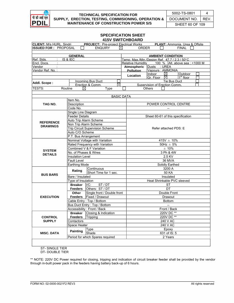
TECHNICAL SPECIFICATION FOR SUPPLY, ERECTION, TESTING, COMMISIONING, OPERATION &
MAINTENANCE OF CONSTRUCTION POWER S/S
5002-TS-0801 4 DOCUMENT NO. REV.
SHEET 60 OF 109
FORM NO: 02-0000-0021F2 REV3 All rights reserved
SPECIFICATION SHEET 415V SWITCHBOARD
CLIENT: M/s HURL, Sindri PROJECT: Pre-project Electrical Works PLANT: Ammonia, Urea & OffsiteISSUED FOR : PROPOSAL ENQUIRY ORDER FINAL
GENERAL AMBIENT CONDITION Ref. Stds. : IS & IEC Temp. Max./Min./Design Ref. 47.7 / 2.3 / 50°CEncl. Docs. : Relative Humidity 100 % Alt. above sea : <1000 MVendor : Atmospheric
PollutionDusts : UREA
Vendor Ref. No. : Vapours : AMMONIA Location Indoor Outdoor Gr. Floor 1st floor Addl. Scope : Incoming Bus Duct Tie Bus Duct
Erection & Comm. Supervision of Erection Comm. TESTS: Routine Type Others
BASIC DATA
TAG NO. Item No. Description POWER CONTROL CENTRE Code No. --
REFERENCE DRAWINGS
Single Line Diagram Feeder Details Sheet 60-61 of this specification Auto Trip Alarm Scheme
Refer attached PDS: E Non Trip Alarm Scheme Trip Circuit Supervision Scheme Auto C/O Scheme P.T. Bus Arrangement
SYSTEM DETAILS
Nominal Voltage with Variation 415V ± 10% Rated Frequency with Variation 50Hz ± 5% Combined V & F Variation ± 10% No. of Phases & Wires 3 Ph & 4W Insulation Level 2.5 KV Fault Level 36 MVA Earthing Mode Solidly Earthed
BUS BARS Rating Continuous 3200 A
Short Time for 1 sec. 50 KA Bare / Insulated Insulated Type of Insulation Heat Shrinkable PVC sleeved
EXECUTION
Breaker Feeders
I/C: ST / DT ST Others: ST / DT DT
Other Feeders
Single front / Double front Double Front Fixed / Drawout Drawout
Cable Entry : Top / Bottom Bottom Bus Duct Entry : Top / Bottom -- Accessibility : Front / Back Front / Back
CONTROL SUPPLY
Breaker Feeders
Closing & Indication 220V DC ** Tripping 220V DC **
Contactors 240 V AC Space Heater 240 V AC
MISC. DATA Painting Type Epoxy Shade 631 of IS: 5
Period for which Spares required 2 Years
ST- SINGLE TIER DT- DOUBLE TIER
** NOTE: 220V DC Power required for closing, tripping and indication of circuit breaker feeder shall be provided by the vendor through in-built power pack in the feeders having battery back-up of 6 hours.

TECHNICAL SPECIFICATION FOR SUPPLY, ERECTION, TESTING, COMMISIONING, OPERATION &
MAINTENANCE OF CONSTRUCTION POWER S/S
5002-TS-0801 4 DOCUMENT NO. REV.
SHEET 61 OF 109
FORM NO: 02-0000-0021F2 REV3 All rights reserved
FEEDER DETAILS (BREAKER CONTROLLED FEEDERS)
CLIENT: M/s HURL, Sindri PROJECT: Pre-project Electrical Works PLANT: Ammonia, Urea & OffsiteISSUED FOR : PROPOSAL ENQUIRY ORDER FINAL SWITCH BOARD DESCRIPTION: 415V POWER CONTROL CENTRE CODE NO.:
GENERAL
Feeder No. 12
Feeder Description Incomer
Eqpt. Code No. -- Load in KW / Amp - / 3200A Ref. Scheme Drgs. Refer attached PDS: E
C. B. Rating 3200 A (ACB) Operating Mechanism MWS
CURRENT TRF.
Metering 3-3000/1 A Protection 3-3000/1 A O/C & E/F / Combined Motor Protn. -- Restricted Earth Fault Protn. -- Stand By Earth Fault Protn. YES
V. T. Ratio 415/√3/110/√3 Connection : Bus / Feeder YES/YES
METERS
Ammeter YES (0-3000A) Voltmeter YES (0-500V) KWH/KW YES/YES PF Meter YES Frequency Meter YES
PROTECTIVE RELAY
Combined Motor Protn. -- Over current IDMTL YES
High Set Inst. --
Earth Fault Res. IDMTL YES Inst. -- Restricted -- Stand by --
Under Voltage with Timer YES PT Fuse Failure YES Stalling / Single Phasing --
AUX. RELAY
Tripping Relay Elect. Fault YES Process Fault --
Trip Circuit Supervision YES Buchholz Alarm / Trip -- WTI / OTI Alarm -- Low Oil Level Alarm -- Alarm / Alarm Cancellation -- Others as required YES
CONTROL SWITCH
Trip - Neutral – Close / off-auto-On YES / -- Auto – Manual / Local – Remote -- / YES ASS / VSS YES / YES Local-Remote-Auto --
PUSH BUTTON
Emg. Trip (T) / Test (Te) -- / Yes Alarm Accept (AC) / Reset I YES / YES Defeat Interlock or Momentary Paralleling YES Emgy. Trip of HVCB --
SIGNAL LAMPS
ON(R)/ OFF(G) YES / YES Non Trip (B) / Auto Trip (A) -- / YES Trip Ckt. Healthy (W) YES Panel Space Heater ON -- Ready for Service / Test YES / YES
AUX. EQPT. Limit Switch: Service / Test YES / YES MCB for Motor Space Heater -- Others as required YES
CABLING DATA
Power Cable: 1.1KV, XLPE-A-FRLS PVC 8R-3.5Cx400 mm2 (Cu)Space Heater:1.1KV, XLPE-A-FRLS PVC -- Control Cable: 1.1KV, XLPE-A-FRLS PVC 3-3x2.5 mm2 (Cu)

TECHNICAL SPECIFICATION FOR SUPPLY, ERECTION, TESTING, COMMISIONING, OPERATION &
MAINTENANCE OF CONSTRUCTION POWER S/S
5002-TS-0801 4 DOCUMENT NO. REV.
SHEET 62 OF 109
FORM NO: 02-0000-0021F2 REV3 All rights reserved
FEEDER DETAILS (415V SWITCHBOARD)
SF – Power Feeder shall be SFU with metering CT and Ammeter as per attached PDS 8485.
CLIENT: M/s HURL, Sindri PROJECT: Pre-project Electrical Works PLANT: Ammonia, Urea & Offsite ISSUED FOR : PROPOSAL ENQUIRY ORDER FINAL SWITCH BOARD DESCRIPTION: 415V Switch Board CODE NO.:
Feeder No. Feeder Description
and Code No.
Rating Ref. Scheme Drg.
Fdr.Type Power Cable
Size (mm2)
Remarks KW Amp.
1 Feeder for MLDB
-- 630A PDS: 8485 SF (Power Feeder)
LATER
2 Construction Power to DM
plant
-- 630A PDS: 8485 -do- LATER
3 Construction Power to Inst. Air & Plant Air
System Package
-- 630A PDS: 8485 -do- LATER
4 Spare Power Feeder
-- 630A PDS: 8485 -do- LATER
5 To Welding Socket DB
-- 400A PDS: 8485 -do- LATER
6 Spare Power Feeder
-- 400A PDS: 8485 -do- LATER
7 Future Load -- 250A PDS: 8485 -do- LATER
8 Future Load -- 250A PDS: 8485 -do- LATER
9 Future Load -- 250A PDS: 8485 -do- LATER
10 Spare Power Feeder
-- 250A PDS: 8485 -do- LATER
11 Future Load -- 125A PDS: 8485 -do- LATER
12 -- -- 3200A PDS INCOMER 8R-3.5CX400
sq. mm (Cu)
13 Future Load -- 125A PDS: 8485 SF (Power Feeder)
LATER
14 Future Load -- 125A PDS: 8485 -do- LATER
15 Spare Power Feeder
-- 125A PDS: 8485 -do- LATER
16 Future Load -- 63A PDS: 8485 -do- LATER
17 Future Load -- 63A PDS: 8485 -do- LATER
18 Future Load -- 63A PDS: 8485 -do- LATER
19 Future Load -- 63A PDS: 8485 -do- LATER
20 Spare Power Feeder
-- 63A PDS: 8485 -do- LATER
21 Spare Power Feeder
-- 63A PDS: 8485 -do- LATER
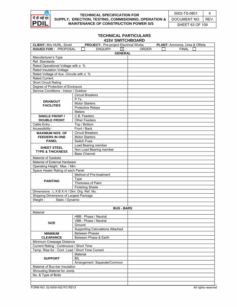
TECHNICAL SPECIFICATION FOR SUPPLY, ERECTION, TESTING, COMMISIONING, OPERATION &
MAINTENANCE OF CONSTRUCTION POWER S/S
5002-TS-0801 4 DOCUMENT NO. REV.
SHEET 63 OF 109
FORM NO: 02-0000-0021F2 REV3 All rights reserved
TECHNICAL PARTICULARS 415V SWITCHBOARD
CLIENT: M/s HURL, Sindri PROJECT: Pre-project Electrical Works PLANT: Ammonia, Urea & Offsite ISSUED FOR : PROPOSAL ENQUIRY ORDER FINAL
GENERAL Manufacturer’s Type Ref. Standards Rated Operational Voltage with ± % Rated Insulation Voltage Rated Voltage of Aux. Circuits with ± % Rated Current Short Circuit Rating Degree of Protection of Enclosure Service Conditions : Indoor / Outdoor
DRAWOUT FACILITIES
Circuit Breakers P.Ts. Motor Starters Protective Relays Meters
SINGLE FRONT / DOUBLE FRONT
C.B. Feeders Other Feeders
Cable Entry : Top / Bottom Accessibility : Front / Back
MAXIMUM NOS. OF FEEDERS IN ONE
PANEL
Circuit Breakers Motor Starters Switch Fuse
SHEET STEEL TYPE & THICKNESS
Load Bearing member Non Load Bearing member Base Channel
Material of Gaskets Material of External Hardware Operating Height : Max. / Min. Space Heater Rating of each Panel
PAINTING
Method of Pre-treatment Type Thickness of Paint Finishing Shade
Dimensions : L X B X H / Dim. Drg. Ref. No. Shipping Dimensions of Largest Package Weight : Static / Dynamic
BUS - BARS Material
SIZE
HBB : Phase / Neutral VBB : Phase / Neutral Ground Supporting Calculations Attached
MINIMUM CLEARANCE
Between Phases Between Phase & Earth
Minimum Creepage Distance Current Rating : Continuous / Short Time Temp. Rise for : Cont. Load / Short Time Current
SUPPORT Material BIL Arrangement :Separate/Common
Material of Bus-bar Insulation Shrouding Material for Joints No. & Type of Bolts
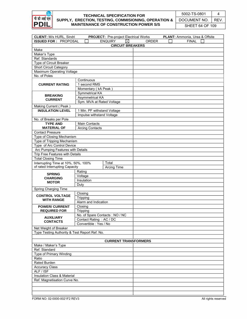
TECHNICAL SPECIFICATION FOR SUPPLY, ERECTION, TESTING, COMMISIONING, OPERATION &
MAINTENANCE OF CONSTRUCTION POWER S/S
5002-TS-0801 4 DOCUMENT NO. REV.
SHEET 64 OF 109
FORM NO: 02-0000-0021F2 REV3 All rights reserved
CLIENT: M/s HURL, Sindri PROJECT: Pre-project Electrical Works PLANT: Ammonia, Urea & Offsite ISSUED FOR : PROPOSAL ENQUIRY ORDER FINAL
CIRCUIT BREAKERS Make Maker’s Type Ref. Standards Type of Circuit Breaker Short Circuit Category Maximum Operating Voltage No. of Poles
CURRENT RATING Continuous 1 second RMS Momentary ( kA Peak )
BREAKING CURRENT
Symmetrical KA Asymmetrical KA Sym. MVA at Rated Voltage
Making Current ( Peak ) INSULATION LEVEL 1 Min. PF withstand Voltage
Impulse withstand Voltage No. of Breaks per Pole
TYPE AND MATERIAL OF
Main Contacts Arcing Contacts
Contact Pressure Type of Closing Mechanism Type of Tripping Mechanism Type of Arc Control Device Arc Pumping Features with Details Trip Free Features with Details Total Closing Time Interrupting Time at 10%, 50%, 100% of rated Interrupting Capacity
Total Arcing Time
SPRING CHARGING
MOTOR
Rating Voltage Insulation Duty
Spring Charging Time
CONTROL VOLTAGE WITH RANGE
Closing Tripping Alarm and Indication
POWER/ CURRENT REQUIRED FOR
Closing Tripping
AUXILIARY CONTACTS
No. of Spare Contacts : NO / NC Contact Rating : AC / DC Convertible : Yes / No
Net Weight of Breaker Type Testing Authority & Test Report Ref. No.
CURRENT TRANSFORMERS Make / Maker’s Type Ref. Standard Type of Primary Winding Ratio Rated Burden Accuracy Class ALF / ISF Insulation Class & Material Ref. Magnetisation Curve No.
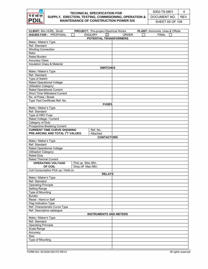
TECHNICAL SPECIFICATION FOR SUPPLY, ERECTION, TESTING, COMMISIONING, OPERATION &
MAINTENANCE OF CONSTRUCTION POWER S/S
5002-TS-0801 4 DOCUMENT NO. REV.
SHEET 65 OF 109
FORM NO: 02-0000-0021F2 REV3 All rights reserved
CLIENT: M/s HURL, Sindri PROJECT: Pre-project Electrical Works PLANT: Ammonia, Urea & Offsite ISSUED FOR : PROPOSAL ENQUIRY ORDER FINAL
POTENTIAL TRANSFORMERS Make / Maker’s Type Ref. Standard Winding Connection Ratio Rated Burden Accuracy Class Insulation Class & Material
SWITCHES Make / Maker’s Type Ref. Standard Type of Switch Rated Operational Voltage Utilisation Category Rated Operational Current Short Time Withstand Current No. of Poles / Break Type Test Certificate Ref. No.
FUSES Make / Maker’s Type Ref. Standard Type of HRC Fuse Rated Voltage / Current Category of Duty Prospective Breaking Current CURRENT TIME CURVE SHOWING PRE-ARCING AND TOTAL I2T VALUES
Ref. No. Attached
CONTACTORS Make / Maker’s Type Ref. Standard Rated Operational Voltage Utilisation Category Rated Duty Rated Thermal Current
OPERATING VOLTAGE OF COIL
Pick up Max./Min. Drop off Max./Min.
Coil Consumption Pick up / Hold on RELAYS
Make / Maker’s Type Ref. Standard Operating Principle Setting Range Type of Mounting Burden Reset : Hand or Self Flag Indication Type Ref. Characteristic Curve Type Ref. Descriptive catalogue
INSTRUMENTS AND METERS Make / Maker’s Type Ref. Standard Operating Principle Scale Range Accuracy Size Type of Mounting
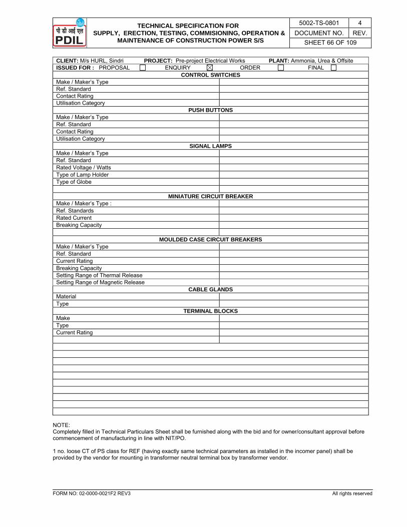
TECHNICAL SPECIFICATION FOR SUPPLY, ERECTION, TESTING, COMMISIONING, OPERATION &
MAINTENANCE OF CONSTRUCTION POWER S/S
5002-TS-0801 4 DOCUMENT NO. REV.
SHEET 66 OF 109
FORM NO: 02-0000-0021F2 REV3 All rights reserved
CLIENT: M/s HURL, Sindri PROJECT: Pre-project Electrical Works PLANT: Ammonia, Urea & Offsite ISSUED FOR : PROPOSAL ENQUIRY ORDER FINAL
CONTROL SWITCHES Make / Maker’s Type Ref. Standard Contact Rating Utilisation Category
PUSH BUTTONS Make / Maker’s Type Ref. Standard Contact Rating Utilisation Category
SIGNAL LAMPS Make / Maker’s Type Ref. Standard Rated Voltage / Watts Type of Lamp Holder Type of Globe
MINIATURE CIRCUIT BREAKER Make / Maker’s Type : Ref. Standards Rated Current Breaking Capacity
MOULDED CASE CIRCUIT BREAKERS
Make / Maker’s Type Ref. Standard Current Rating Breaking Capacity Setting Range of Thermal Release Setting Range of Magnetic Release
CABLE GLANDS Material Type
TERMINAL BLOCKS Make Type Current Rating
NOTE: Completely filled in Technical Particulars Sheet shall be furnished along with the bid and for owner/consultant approval before commencement of manufacturing in line with NIT/PO. 1 no. loose CT of PS class for REF (having exactly same technical parameters as installed in the incomer panel) shall be provided by the vendor for mounting in transformer neutral terminal box by transformer vendor.
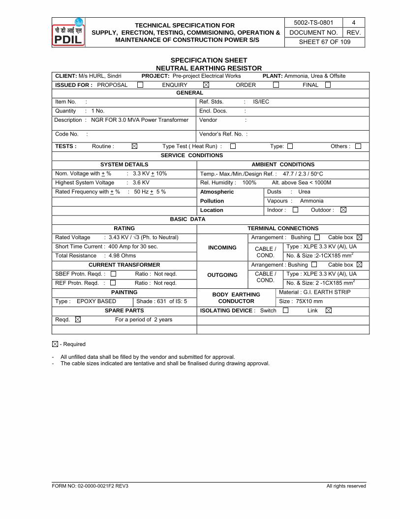
TECHNICAL SPECIFICATION FOR SUPPLY, ERECTION, TESTING, COMMISIONING, OPERATION &
MAINTENANCE OF CONSTRUCTION POWER S/S
5002-TS-0801 4 DOCUMENT NO. REV.
SHEET 67 OF 109
FORM NO: 02-0000-0021F2 REV3 All rights reserved
SPECIFICATION SHEET NEUTRAL EARTHING RESISTOR
CLIENT: M/s HURL, Sindri PROJECT: Pre-project Electrical Works PLANT: Ammonia, Urea & Offsite ISSUED FOR : PROPOSAL ENQUIRY ORDER FINAL GENERAL Item No. : Ref. Stds. : IS/IEC Quantity : 1 No. Encl. Docs. : Description : NGR FOR 3.0 MVA Power Transformer Vendor :
Code No. : Vendor’s Ref. No. :
TESTS : Routine : Type Test ( Heat Run) : Type: Others : SERVICE CONDITIONS
SYSTEM DETAILS AMBIENT CONDITIONS Nom. Voltage with + % : 3.3 KV + 10% Temp.- Max./Min./Design Ref. : 47.7 / 2.3 / 50°C Highest System Voltage : 3.6 KV Rel. Humidity : 100% Alt. above Sea < 1000M Rated Frequency with + % : 50 Hz + 5 % Atmospheric Dusts : Urea
Pollution Vapours : Ammonia
Location Indoor : Outdoor :
BASIC DATA RATING TERMINAL CONNECTIONS
Rated Voltage : 3.43 KV / √3 (Ph. to Neutral)
INCOMING
Arrangement : Bushing Cable box Short Time Current : 400 Amp for 30 sec. CABLE /
COND. Type : XLPE 3.3 KV (Al), UA
Total Resistance : 4.98 Ohms No. & Size :2-1CX185 mm2
CURRENT TRANSFORMER
OUTGOING
Arrangement : Bushing Cable box SBEF Protn. Reqd. : Ratio : Not reqd. CABLE /
COND. Type : XLPE 3.3 KV (Al), UA
REF Protn. Reqd. : Ratio : Not reqd. No. & Size: 2 -1CX185 mm2
PAINTING BODY EARTHING CONDUCTOR
Material : G.I. EARTH STRIP Type : EPOXY BASED Shade : 631 of IS: 5 Size : 75X10 mm
SPARE PARTS ISOLATING DEVICE : Switch Link Reqd. For a period of 2 years
- Required
- All unfilled data shall be filled by the vendor and submitted for approval. - The cable sizes indicated are tentative and shall be finalised during drawing approval.

TECHNICAL SPECIFICATION FOR SUPPLY, ERECTION, TESTING, COMMISIONING, OPERATION &
MAINTENANCE OF CONSTRUCTION POWER S/S
5002-TS-0801 4 DOCUMENT NO. REV.
SHEET 68 OF 109
FORM NO: 02-0000-0021F2 REV3 All rights reserved
TECHNICAL PARTICULARS NEUTRAL EARTHING RESISTOR
NOTE: Completely filled in Technical Particulars Sheet shall be furnished along with the bid and for owner/consultant approval
before commencement of manufacturing in line with NIT/PO.
CLIENT: M/s HURL, Sindri PROJECT: Pre-project Electrical Works PLANT: Ammonia, Urea & Offsite ISSUED FOR : PROPOSAL ENQUIRY ORDER FINAL
GENERAL Item No. : Ref. Stds. : Quantity : Make : Description : Maker’s Type : Code No. :
RESISTOR Material of element : Construction : Punched Formed Temp. rise over ambient : Continuous current rating : Duration for short time rating : No. of elements per Bank : NUMBER OF
BANKS IN Series : Parallel :
Resistance of each Element : Temp. Co-efficient per o C : Specific Resistance :
BUSHING / SUPPORT INSULATORS Make & Maker’s Type : Ref. Stds.: Rated Voltage : Material of Construction : INSULATION
LEVEL Impulse : Power Freq. :
Min. Clearance to Earth : Min. Creepage distance :
ISOLATING SWITCH Make & Maker’s Type : Ref. Stds. : Rated Voltage : Rated Current : No. of Aux. Contacts :
CURRENT TRANSFORMER Make & Maker’s Type : Ref. Stds. : Accuracy Class : Burden ( VA ) :
INTERCONNECTING STRIP Material of connecting Strip : Rated Current : Arrangement of connection :
HOUSING Degree of Protection : Thickness of sheet steel : Material of Ext. Hardwares < 8mm/ >8mm : Temp. Rise over Ambient : Size ( LXBXH ) : Total Weight :
CABLE GLAND Make : Type of Material :
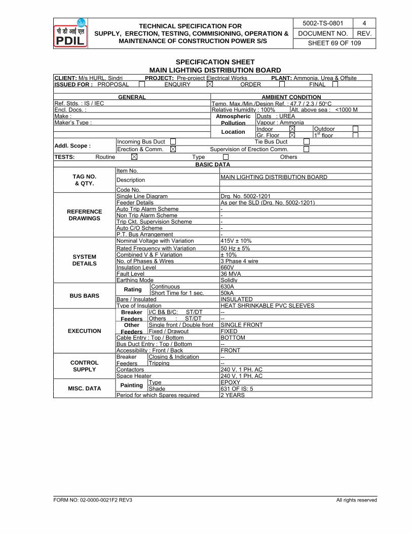
TECHNICAL SPECIFICATION FOR SUPPLY, ERECTION, TESTING, COMMISIONING, OPERATION &
MAINTENANCE OF CONSTRUCTION POWER S/S
5002-TS-0801 4 DOCUMENT NO. REV.
SHEET 69 OF 109
FORM NO: 02-0000-0021F2 REV3 All rights reserved
SPECIFICATION SHEET MAIN LIGHTING DISTRIBUTION BOARD
CLIENT: M/s HURL, Sindri PROJECT: Pre-project Electrical Works PLANT: Ammonia, Urea & OffsiteISSUED FOR : PROPOSAL ENQUIRY ORDER FINAL
GENERAL AMBIENT CONDITION Ref. Stds. : IS / IEC Temp. Max./Min./Design Ref. : 47.7 / 2.3 / 50°CEncl. Docs. : Relative Humidity : 100% Alt. above sea : <1000 MMake : Atmospheric
PollutionDusts : UREA
Maker’s Type : Vapour : Ammonia Location Indoor Outdoor Gr. Floor 1st floor
Addl. Scope : Incoming Bus Duct Tie Bus Duct Erection & Comm. Supervision of Erection Comm.
TESTS: Routine Type Others BASIC DATA
TAG NO. & QTY.
Item No. Description MAIN LIGHTING DISTRIBUTION BOARD
Code No.
REFERENCE DRAWINGS
Single Line Diagram Drg. No. 5002-1201Feeder Details As per the SLD (Drg. No. 5002-1201) Auto Trip Alarm Scheme -Non Trip Alarm Scheme -Trip Ckt. Supervision Scheme -Auto C/O Scheme -P.T. Bus Arrangement -
SYSTEM DETAILS
Nominal Voltage with Variation 415V ± 10% Rated Frequency with Variation 50 Hz ± 5%Combined V & F Variation ± 10%No. of Phases & Wires 3 Phase 4 wireInsulation Level 660VFault Level 36 MVAEarthing Mode Solidly
BUS BARS Rating Continuous 630A
Short Time for 1 sec. 50kABare / Insulated INSULATEDType of Insulation HEAT SHRINKABLE PVC SLEEVES
EXECUTION
Breaker Feeders
I/C B& B/C: ST/DT --Others : ST/DT --
Other Feeders
Single front / Double front SINGLE FRONTFixed / Drawout FIXED
Cable Entry : Top / Bottom BOTTOMBus Duct Entry : Top / Bottom --Accessibility : Front / Back FRONT
CONTROL SUPPLY
Breaker Feeders
Closing & Indication --Tripping --
Contactors 240 V, 1 PH, ACSpace Heater 240 V, 1 PH, AC
MISC. DATA Painting Type EPOXYShade 631 OF IS: 5
Period for which Spares required 2 YEARS

TECHNICAL SPECIFICATION FOR SUPPLY, ERECTION, TESTING, COMMISIONING, OPERATION &
MAINTENANCE OF CONSTRUCTION POWER S/S
5002-TS-0801 4 DOCUMENT NO. REV.
SHEET 70 OF 109
FORM NO: 02-0000-0021F2 REV3 All rights reserved
TECHNICAL PARTICULARS MAIN LIGHTING DISTRIBUTION BOARD
CLIENT: M/s HURL, Sindri PROJECT: Pre-project Electrical Works PLANT: Ammonia, Urea & Offsite ISSUED FOR : PROPOSAL ENQUIRY ORDER FINAL
GENERAL Item No. : Description : Code No. Ref. Stds. : Make : Maker’s Type :
TECHNICAL DATA
BUS - BARS Material & Grade :
Size Phase Neutral
ENCLOSURES Material : Thickness : Cross - Sectional area :
MIN. CLEARA- NCE BETWEEN
Live Parts : Live Parts & Accidentally Dangerous Parts :
Min. Creepage Distance :
TEMP. RISE OVER AMBIENT
Bus Bar : Enclosure :
BUS - BAR SUPPORTS
Material & Grade : Interval :
Resistance of Bus - Bar per M : Reactance of Bus - Bar per M :
EARTHING No. of Conductors : Material & Size :
No. of Inspection Windows : No. of Ventilating Louvers : No. of Expansion Joints : Phase Cross - Over Provided :
FIRE RESISTANCE BARRIERS PROVIDED AT
Transformer End : Switch Gear End :
Drain Plug Provided :
NOTE: Completely filled in Technical Particulars Sheet shall be furnished along with the bid and for owner/consultant approval
before commencement of manufacturing in line with NIT/PO.
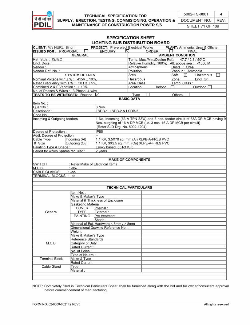
TECHNICAL SPECIFICATION FOR SUPPLY, ERECTION, TESTING, COMMISIONING, OPERATION &
MAINTENANCE OF CONSTRUCTION POWER S/S
5002-TS-0801 4 DOCUMENT NO. REV.
SHEET 71 OF 109
FORM NO: 02-0000-0021F2 REV3 All rights reserved
SPECIFICATION SHEET LIGHTING SUB DISTRIBUTION BOARD
CLIENT: M/s HURL, Sindri PROJECT: Pre-project Electrical Works PLANT: Ammonia, Urea & OffsiteISSUED FOR : PROPOSAL ENQUIRY ORDER FINAL
GENERAL AMBIENT CONDITION Ref. Stds. : IS/IEC Temp. Max./Min./Design Ref.: 47.7 / 2.3 / 50°CEncl. Docs. : Relative Humidity: 100%; Alt. above sea : <1000 MVendor : Atmospheric Dusts : Urea Vendor Ref. No. : Pollution Vapour : Ammonia
SYSTEM DETAILS Area Safe Hazardous Nominal Voltage with ± % : 415V ± 10%, Hazardous Zone : Encl. Gr. : Rated Frequency with ± % : 50 Hz ± 5%, Area Class Temp. Class : Combined V & F Variation : ± 10%, Location Indoor Outdoor No. of Phases & Wires : 3-Phase, 4-wire TESTS TO BE WITNESSED: Routine Type Others
BASIC DATA Item No. : Quantity : 3 Nos.Description : LSDB-1, LSDB-2 & LSDB-3 Code No. Incoming & Outgoing feeders 1 No. Incoming (63 A TPN SFU) and 3 nos. feeder circuit of 63A DP MCB having 9
Nos. outgoing of 16 A DP MCB (i.e. 3 nos. 16 A DP MCB per circuit) (Refer SLD Drg. No. 5002-1204)
Degree of Protection : IP55Addl. Degree of Protection : -- Cable Type Incoming (Al) 1.1 KV, 3.5X70 sq. mm (Al) XLPE-A-FRLS PVC & Size Outgoing (Cu) 1.1 KV, 3X2.5 sq. mm. (Cu) XLPE-A-FRLS PVC Painting Type & Shade : Epoxy based, 631of IS:5Period for which Spares required : 2 years
MAKE OF COMPONENTS
SWITCH : Refer Make of Electrical ItemsM.C.B. : -do- CABLE GLANDS : -do- TERMINAL BLOCKS : -do-
TECHNICAL PARTICULARS Item No. : Make & Maker’s Type Material & Thickness of Enclosure Gasketing Material
COVER Internal :General TYPE External :
PAINTING Pre treatment Shade Material of Ext. Hardware < 8mm / > 8mm Dimensional Drawing Reference No. : Weight : Make & Maker’s Type Reference Standards
M.C.B. Category of Duty : Rated Current : No. of Poles : Type of Neutral :
Terminal Block Make & Type Rated Current
Cable Gland Type : Material :
NOTE: Completely filled in Technical Particulars Sheet shall be furnished along with the bid and for owner/consultant approval
before commencement of manufacturing.
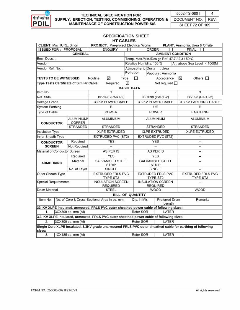
TECHNICAL SPECIFICATION FOR SUPPLY, ERECTION, TESTING, COMMISIONING, OPERATION &
MAINTENANCE OF CONSTRUCTION POWER S/S
5002-TS-0801 4 DOCUMENT NO. REV.
SHEET 72 OF 109
FORM NO: 02-0000-0021F2 REV3 All rights reserved
SPECIFICATION SHEET HT CABLES
CLIENT: M/s HURL, Sindri PROJECT: Pre-project Electrical Works PLANT: Ammonia, Urea & Offsite ISSUED FOR : PROPOSAL ENQUIRY ORDER FINAL
GENERAL AMBIENT CONDITION Encl. Docs. : Temp. Max./Min./Design Ref. 47.7 / 2.3 / 50°C Vendor : Relative Humidity: 100 % Alt. above Sea Level < 1000M Vendor Ref. No. : Atmospheric
Pollution Dusts : Urea
Vapours : Ammonia TESTS TO BE WITNESSED: Routine Type Acceptance Others Type Tests Certificate of Similar Cable : Required Not required
BASIC DATA Item No. 1 2 3 Ref. Stds. IS:7098 (PART-2) IS:7098 (PART-2) IS:7098 (PART-2) Voltage Grade 33 KV POWER CABLE 3.3 KV POWER CABLE 3.3 KV EARTHING CABLE System Earthing E UE E Type of Cable POWER POWER EARTHING
CONDUCTOR ALUMINIUM/
COPPER ALUMINIUM ALUMINIUM ALUMINIUM
STRANDED STRANDED STRANDED STRANDED Insulation Type XLPE EXTRUDED XLPE EXTRUDED XLPE EXTRUDED Inner Sheath Type EXTRUDED PVC (ST2) EXTRUDED PVC (ST2) --
CONDUCTOR SCREEN
Required YES YES -- Not Required -- -- --
Material of Conductor Screen AS PER IS AS PER IS --
ARMOURING
Required YES YES -- Material GALVANISED STEEL
STRIP GALVANISED STEEL
STRIP --
No. of Layer SINGLE SINGLE -- Outer Sheath Type EXTRUDED FRLS PVC
TYPE-ST2 EXTRUDED FRLS PVC
TYPE-ST2 EXTRUDED FRLS PVC
TYPE-ST2 Special Requirements INSULATION SCREEN
REQUIRED INSULATION SCREEN
REQUIRED --
Drum Material STEEL WOOD WOOD BILL OF QUANTITY
Item No. No. of Core & Cross-Sectional Area in sq. mm. Qty. in Mtr. Preferred Drum Length
Remarks
33 KV XLPE insulated, armoured, FRLS PVC outer sheathed power cable of following sizes: 1. 3CX300 sq. mm (Al) Refer SOR LATER
3.3 KV XLPE insulated, armoured, FRLS PVC outer sheathed power cable of following sizes: 2. 3CX300 sq. mm (Al) Refer SOR LATER
Single Core XLPE insulated, 3.3KV grade unarmoured FRLS PVC outer sheathed cable for earthing of following sizes:
3. 1CX185 sq. mm (Al) Refer SOR LATER

TECHNICAL SPECIFICATION FOR SUPPLY, ERECTION, TESTING, COMMISIONING, OPERATION &
MAINTENANCE OF CONSTRUCTION POWER S/S
5002-TS-0801 4 DOCUMENT NO. REV.
SHEET 73 OF 109
FORM NO: 02-0000-0021F2 REV3 All rights reserved
SPECIFICATION SHEET LT POWER & CONTROL CABLES
CLIENT: M/s HURL, Sindri PROJECT: Pre-project Electrical Works PLANT: Ammonia, Urea & Offsite ISSUED FOR : PROPOSAL ENQUIRY ORDER FINAL
GENERAL AMBIENT CONDITION Encl. Docs. : Temp. Max./Min./Design Ref. 47.7 / 2.3 / 50°C Vendor : Relative Humidity: 100 % Alt. above Sea Level < 1000M Vendor Ref. No. : Atmospheric
Pollution Dusts : Urea
Vapours : Ammonia TESTS TO BE WITNESSED: Routine Type Acceptance Others Type Tests Certificate of Similar Cable : Required Not required
BASIC DATA Item No. 1-11 12-15 16-18 Ref. Stds. IS:7098 (PART-1) IS:7098 (PART-1) IS:7098 (PART-1) Voltage Grade 1.1 KV POWER CABLE 1.1 KV CONTROL CABLE 1.1 KV EARTHING CABLESystem Earthing NEUTRAL SOLIDLY
EARTHED NEUTRAL SOLIDLY
EARTHED NEUTRAL SOLIDLY
EARTHED Type of Cable POWER CONTROL EARTHING
CONDUCTOR ALUMINIUM/
COPPER ALUMINIUM / COPPER COPPER ALUMINIUM
STRANDED STRANDED STRANDED STRANDED Insulation Type XLPE EXTRUDED XLPE EXTRUDED XLPE EXTRUDED Inner Sheath Type EXTRUDED PVC (ST2) EXTRUDED PVC (ST2) --
CONDUCTOR SCREEN
Required -- -- -- Not Required -- -- --
Material of Conductor Screen -- -- --
ARMOURING
Required YES YES -- Material GALVANISED STEEL
STRIP / WIRE GALVANISED STEEL WIRE --
No. of Layer SINGLE SINGLE -- Outer Sheath Type EXTRUDED FRLS PVC
TYPE-ST2 EXTRUDED FRLS PVC
TYPE-ST2 EXTRUDED FRLS PVC
TYPE-ST2 Special Requirements -- -- -- Drum Material WOOD WOOD WOOD
BILL OF QUANTITY Item No. No. of Core & Cross-Sectional
Area in Sq. mm. Qty. in M. Preferred
Drum LengthRemarks
1.1 KV XLPE insulated, armoured, FRLS PVC outer sheathed, Power cables of following sizes:- 1. 3.5CX400 sq. mm (Cu) Refer SOR LATER 2. 3.5CX300 sq. mm (Al) LATER 3. 3.5CX185 sq. mm (Al) LATER 4. 3.5CX70 sq. mm (Al) LATER 5. 3.5CX50 sq. mm (Al) LATER 6. 3.5CX35 sq. mm (Al) LATER 7. 4CX16 sq. mm (Al) LATER 8. 3CX10 sq. mm (Cu) LATER 9. 3CX6 sq. mm (Cu) LATER 10. 3CX4 sq. mm (Cu) LATER 11. 3CX2.5 sq. mm (Cu) LATER
1.1 KV XLPE insulated, armoured, FRLS PVC outer sheathed, Control cables of following sizes:- 12. 5CX2.5 sq. mm (Cu) Refer SOR LATER 13. 7CX2.5 sq. mm (Cu) LATER 14. 12CX2.5 sq. mm (Cu) LATER 15. 19CX2.5 sq. mm (Cu) LATER
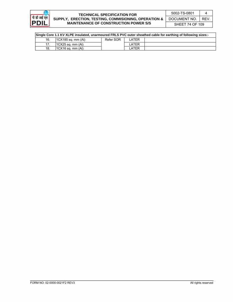
TECHNICAL SPECIFICATION FOR SUPPLY, ERECTION, TESTING, COMMISIONING, OPERATION &
MAINTENANCE OF CONSTRUCTION POWER S/S
5002-TS-0801 4 DOCUMENT NO. REV.
SHEET 74 OF 109
FORM NO: 02-0000-0021F2 REV3 All rights reserved
Single Core 1.1 KV XLPE insulated, unarmoured FRLS PVC outer sheathed cable for earthing of following sizes:- 16. 1CX185 sq. mm (Al) Refer SOR LATER 17. 1CX25 sq. mm (Al) LATER 18. 1CX16 sq. mm (Al) LATER
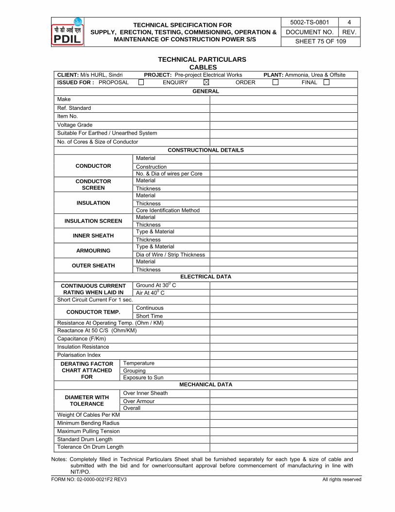
TECHNICAL SPECIFICATION FOR SUPPLY, ERECTION, TESTING, COMMISIONING, OPERATION &
MAINTENANCE OF CONSTRUCTION POWER S/S
5002-TS-0801 4 DOCUMENT NO. REV.
SHEET 75 OF 109
FORM NO: 02-0000-0021F2 REV3 All rights reserved
TECHNICAL PARTICULARS CABLES
CLIENT: M/s HURL, Sindri PROJECT: Pre-project Electrical Works PLANT: Ammonia, Urea & Offsite ISSUED FOR : PROPOSAL ENQUIRY ORDER FINAL
GENERAL Make Ref. Standard Item No. Voltage Grade Suitable For Earthed / Unearthed System No. of Cores & Size of Conductor
CONSTRUCTIONAL DETAILS
CONDUCTOR Material Construction No. & Dia of wires per Core
CONDUCTOR SCREEN
Material Thickness
INSULATION Material Thickness Core Identification Method
INSULATION SCREEN Material Thickness
INNER SHEATH Type & Material Thickness
ARMOURING Type & Material Dia of Wire / Strip Thickness
OUTER SHEATH Material Thickness
ELECTRICAL DATA CONTINUOUS CURRENT RATING WHEN LAID IN
Ground At 300 C Air At 400 C
Short Circuit Current For 1 sec.
CONDUCTOR TEMP. Continuous Short Time
Resistance At Operating Temp. (Ohm / KM) Reactance At 50 C/S (Ohm/KM) Capacitance (F/Km) Insulation Resistance Polarisation Index
DERATING FACTOR CHART ATTACHED
FOR
Temperature Grouping Exposure to Sun
MECHANICAL DATA
DIAMETER WITH TOLERANCE
Over Inner Sheath Over Armour Overall
Weight Of Cables Per KM Minimum Bending Radius Maximum Pulling Tension Standard Drum Length Tolerance On Drum Length
Notes: Completely filled in Technical Particulars Sheet shall be furnished separately for each type & size of cable and submitted with the bid and for owner/consultant approval before commencement of manufacturing in line with NIT/PO.
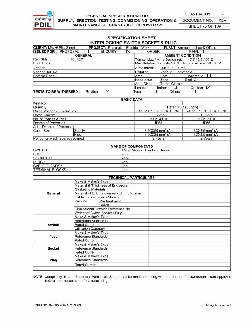
TECHNICAL SPECIFICATION FOR SUPPLY, ERECTION, TESTING, COMMISIONING, OPERATION &
MAINTENANCE OF CONSTRUCTION POWER S/S
5002-TS-0801 4 DOCUMENT NO. REV.
SHEET 76 OF 109
FORM NO: 02-0000-0021F2 REV3 All rights reserved
SPECIFICATION SHEET INTERLOCKING SWITCH SOCKET & PLUG
CLIENT: M/s HURL, Sindri PROJECT: Pre-project Electrical Works PLANT: Ammonia, Urea & OffsiteISSUED FOR : PROPOSAL ENQUIRY ORDER FINAL
GENERAL AMBIENT CONDITION Ref. Stds. : IS / IEC Temp.- Max / Min / Design ref.: 47.7 / 2.3 / 50°CEncl. Docs. : Max Relative Humidity 100% Alt. above sea : <1000 M Vendor : Atmospheric Dusts : Urea Vendor Ref. No. : Pollution Vapour : Ammonia Sample Reqd. : Area Safe Hazardous Hazardous Zone : Encl. Gr. : Area Class Temp. Class : Location : Indoor Outdoor TESTS TO BE WITNESSED : Routine Type Others
BASIC DATAItem No. Quantity Refer SOR (Supply) Rated Voltage & Frequency 415V ± 10 %, 50Hz ± 5% 240V ± 10 %, 50Hz ± 5%Rated Current 63 Amp 15 AmpNo. of Phases & Pins 3 Ph, 4 Pin 1 Ph, 3 PinDegree of Protection IP55 IP55Addl. Degree of Protection -- --Cable Size Supply 3.5CX50 mm2 (Al) 3CX2.5 mm2 (Al) Plug 3.5CX25 mm2 (Al) 3CX2.5 mm2 (Al)Period for which Spares required 2 Years 2 Years
MAKE OF COMPONENTS SWITCH : Refer Make of Electrical ItemsFUSE: -do-SOCKETS : -do-PLUG : -do-CABLE GLANDS : -do-TERMINAL BLOCKS : -do-
TECHNICAL PARTICULARS Make & Maker’s Type Material & Thickness of Enclosure Gasketing Materials
General Material of Ext. Hardwares < 8mm / > 8mm Cable glands Type & Material Painting Pre treatment Shade Dimensional Drawing Reference No. Weight of Switch Socket / Plug Make & Maker’s Type Reference Standards
Switch Rated Current Utilisation Category Make & Maker’s Type
Fuse Reference Standards Rated Current Make & Maker’s Type
Socket Reference Standards Rated Current Make & Maker’s Type
Plug Reference Standards Rated Current NOTE: Completely filled in Technical Particulars Sheet shall be furnished along with the bid and for owner/consultant approval
before commencement of manufacturing.
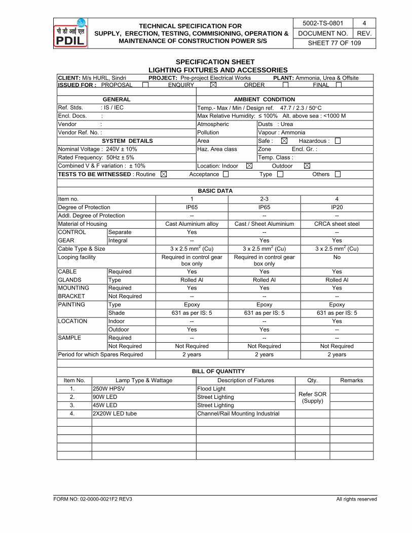
TECHNICAL SPECIFICATION FOR SUPPLY, ERECTION, TESTING, COMMISIONING, OPERATION &
MAINTENANCE OF CONSTRUCTION POWER S/S
5002-TS-0801 4 DOCUMENT NO. REV.
SHEET 77 OF 109
FORM NO: 02-0000-0021F2 REV3 All rights reserved
SPECIFICATION SHEET LIGHTING FIXTURES AND ACCESSORIES
CLIENT: M/s HURL, Sindri PROJECT: Pre-project Electrical Works PLANT: Ammonia, Urea & OffsiteISSUED FOR : PROPOSAL ENQUIRY ORDER FINAL
GENERAL AMBIENT CONDITION Ref. Stds. : IS / IEC Temp.- Max / Min / Design ref. 47.7 / 2.3 / 50°C Encl. Docs. : Max Relative Humidity: ≤ 100% Alt. above sea : <1000 M Vendor : Atmospheric Dusts : Urea Vendor Ref. No. : Pollution Vapour : Ammonia
SYSTEM DETAILS Area Safe : Hazardous : Nominal Voltage : 240V ± 10% Haz. Area class Zone Encl. Gr. : Rated Frequency: 50Hz ± 5% Temp. Class : Combined V & F variation : ± 10% Location: Indoor Outdoor TESTS TO BE WITNESSED : Routine Acceptance Type Others
BASIC DATA
Item no. 1 2-3 4 Degree of Protection IP65 IP65 IP20 Addl. Degree of Protection -- -- -- Material of Housing Cast Aluminium alloy Cast / Sheet Aluminium CRCA sheet steel CONTROL Separate Yes -- -- GEAR Integral -- Yes Yes Cable Type & Size 3 x 2.5 mm2 (Cu) 3 x 2.5 mm2 (Cu) 3 x 2.5 mm2 (Cu) Looping facility Required in control gear
box only Required in control gear
box only No
CABLE Required Yes Yes Yes GLANDS Type Rolled Al Rolled Al Rolled Al MOUNTING Required Yes Yes Yes BRACKET Not Required -- -- -- PAINTING Type Epoxy Epoxy Epoxy Shade 631 as per IS: 5 631 as per IS: 5 631 as per IS: 5 LOCATION Indoor -- -- Yes Outdoor Yes Yes -- SAMPLE Required -- -- -- Not Required Not Required Not Required Not Required Period for which Spares Required 2 years 2 years 2 years
BILL OF QUANTITY
Item No. Lamp Type & Wattage Description of Fixtures Qty. Remarks 1. 250W HPSV Flood Light
Refer SOR (Supply)
2. 90W LED Street Lighting 3. 45W LED Street Lighting 4. 2X20W LED tube Channel/Rail Mounting Industrial
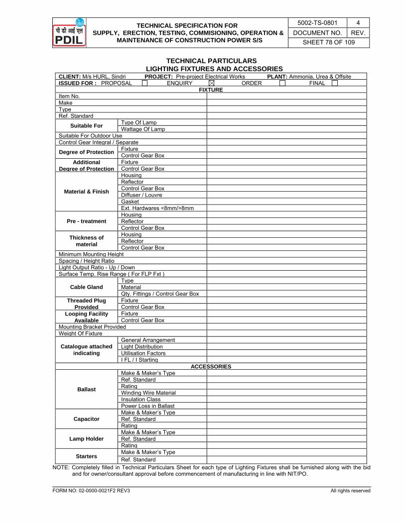
TECHNICAL SPECIFICATION FOR SUPPLY, ERECTION, TESTING, COMMISIONING, OPERATION &
MAINTENANCE OF CONSTRUCTION POWER S/S
5002-TS-0801 4 DOCUMENT NO. REV.
SHEET 78 OF 109
FORM NO: 02-0000-0021F2 REV3 All rights reserved
TECHNICAL PARTICULARS LIGHTING FIXTURES AND ACCESSORIES
CLIENT: M/s HURL, Sindri PROJECT: Pre-project Electrical Works PLANT: Ammonia, Urea & OffsiteISSUED FOR : PROPOSAL ENQUIRY ORDER FINAL
FIXTUREItem No. Make Type Ref. Standard
Suitable For Type Of Lamp Wattage Of Lamp
Suitable For Outdoor Use Control Gear Integral / Separate
Degree of Protection Fixture Control Gear Box
Additional Degree of Protection
Fixture Control Gear Box
Material & Finish
Housing Reflector Control Gear Box Diffuser / Louvre Gasket Ext. Hardwares <8mm/>8mm
Pre - treatment Housing Reflector Control Gear Box
Thickness of material
Housing Reflector Control Gear Box
Minimum Mounting Height Spacing / Height Ratio Light Output Ratio - Up / Down Surface Temp. Rise Range ( For FLP Fxt )
Cable Gland Type Material Qty. Fittings / Control Gear Box
Threaded Plug Provided
Fixture Control Gear Box
Looping Facility Available
Fixture Control Gear Box
Mounting Bracket Provided Weight Of Fixture
Catalogue attached indicating
General Arrangement Light Distribution Utilisation Factors I FL / I Starting
ACCESSORIES
Ballast
Make & Maker’s Type Ref. Standard Rating Winding Wire Material Insulation Class Power Loss in Ballast
Capacitor Make & Maker’s Type Ref. Standard Rating
Lamp Holder Make & Maker’s Type Ref. Standard Rating
Starters Make & Maker’s Type Ref. Standard
NOTE: Completely filled in Technical Particulars Sheet for each type of Lighting Fixtures shall be furnished along with the bid and for owner/consultant approval before commencement of manufacturing in line with NIT/PO.

TECHNICAL SPECIFICATION FOR SUPPLY, ERECTION, TESTING, COMMISIONING, OPERATION &
MAINTENANCE OF CONSTRUCTION POWER S/S
5002-TS-0801 4 DOCUMENT NO. REV.
SHEET 79 OF 109
FORM NO: 02-0000-0021F2 REV3 All rights reserved
TECHNICAL PARTICULARS HIGH MAST COMPONENTS
CLIENT: M/s HURL, Sindri PROJECT: Pre-project Electrical Works PLANT: Ammonia, Urea & Offsite ISSUED FOR : PROPOSAL ENQUIRY ORDER FINAL
1. HIGH MAST LIGHTING STRUCTURE a. Cross section of mast in polygon (no. of sides) b. Overall height of mast (mtrs) c. No. of sections of mast d. Individual section, thickness/dia/length (mm) e. Type of joints & length of overlap joints f. Weight in kgs. of mast (including base plate, door and head
frame etc.)
g. Material of construction h. Pollution Treatment i. Size of base opening door j. Locking arrangement of base opening door k. Size of base plate dia. / thickness l. Lightning protection device
m. Aviation lighting device n. Make / enclosed Drg. ref. o. Civil Design Consideration i) Maximum wind speed ii) Factor of safety for wind load iii) Factor of safety of other load iv) Factor of safety of tower v) Type of foundation vi) Size of foundation vii) Designed load bearing capacity viii) Average soil bearing capacity ix) Design safety factor x) Depth of foundation xi) No. of foundation bolts xii) PCD of foundation bolts xiii) Type of foundation bolts xiv) Bolt Diameter
2. LANTERN CARRIAGE a. Material of construction b. Type of construction c. diameter of carriage ring (mm) d. No. of joints e. Buffer arrangement for carriage and mast f. Load carrying capacity (kg) g. Total weight of assembly with fittings (kg) h. No. of fittings i. Type of fittings / fixture
3. WINCH a. No. of winch, No. of drums b. Gear ratio c. Capacity (kg) d. Operating Speed on full load e. Lubrication / type of lubricant f. Tested load per drum (kg) : i Kg per drum
Ii Kg per winch
g. factor of safety h. Make
4. STAINLESS STEEL WIRE ROPE a. Make b. Grade c. Number of ropes d. Material and construction e. Diameter (mm)

TECHNICAL SPECIFICATION FOR SUPPLY, ERECTION, TESTING, COMMISIONING, OPERATION &
MAINTENANCE OF CONSTRUCTION POWER S/S
5002-TS-0801 4 DOCUMENT NO. REV.
SHEET 80 OF 109
FORM NO: 02-0000-0021F2 REV3 All rights reserved
f. Breaking Load Capacity (kg) g. Factor of Safety
5. CABLE a. Conductor / insulation / No. of cores b. Type c. Make d. Conductor Size / Current Capacity
6. POWER TOOL a. Model / type b. Input Supply c. K.W. d. Operating Speed e. i) Remote control switch PB station ii) Length of control cable provided f. Maximum time taken for : Raising Lowering
7. TORQUE LIMITER a. Model b. Lifting Capacity (kg) c. Adjustability 8. LIGHT FITTINGS a. Type b. No. of fittings in each type c. Type of lamp d. No. of lamps / fittings
9. AVIATION FITTINGS a. Type b. Type of lamp c. No. of lamps / fittings
10. TUBULAR POLE a. Length / each section dia (mm) b. Material c. Treatment of material
11. MISCELLANEOUS a. Earthing connection b. Type / material of JB c. Incoming cable termination with double comp. glands
NOTE: Completely filled in Technical Particulars Sheet shall be furnished along with the bid and for owner/consultant approval
before commencement of manufacturing in line with NIT/PO.

TECHNICAL SPECIFICATION FOR SUPPLY, ERECTION, TESTING, COMMISIONING, OPERATION &
MAINTENANCE OF CONSTRUCTION POWER S/S
5002-TS-0801 4 DOCUMENT NO. REV.
SHEET 81 OF 109
FORM NO: 02-0000-0021F2 REV3 All rights reserved
SPECIFICATION SHEETS JUNCTION BOX
CLIENT: M/s HURL, Sindri PROJECT: Pre-project Electrical Works PLANT: Ammonia, Urea & Offsite ISSUED FOR : PROPOSAL ENQUIRY ORDER FINAL
GENERAL Ref. Stds. IS / IEC Encl. Docs. Make Maker’s type Sample Required Yes No
AMBIENT CONDITIONS Temp. Max. / Min. / Design Ref. 47.7 / 2.3 / 50°C Rel. Humidity 100% Alt. Above Sea Level <1000M ATMOSPHERIC POLLUTION
Dusts UREA (CORROSIVE) Vapours --
Area Safe Hazardous Hazardous area classification Zone: Encl. Gr.: Temp. Class: Location Indoor Outdoor TESTS Routine Type Others
BASIC DATA Item No. 1 Quantity Refer SOR Rated Voltage 240V±10% Rated Frequency 50Hz±5% Rated Current 16A No. of Phases & Wires 1Phase / 3wires (PNE) Application For looping of cable Material of Enclosure LM-6 Shape of Enclosure Round Degree of Protection IP-55 Addl. Degree of Protection -- Type of Cover Dome No. of Outlets 3 nos. + one plug
PAINTING Type: Epoxy based Shade: 631 as per IS: 5
SPARE Required: Yes Duration: 2 Years
No. of Terminals: As required Cable gland: 4 nos. Stopping Plug: 1 no. CABLE SIZE
Incoming -- 3Cx4 mm2 (Cu) / 3Cx6 mm2 (Cu) / 3Cx10 mm2 (Cu) 1.1 KV XLPE ARMOURED FRLS PVC Outgoing -- 3Cx4 mm2 (Cu) / 3Cx6 mm2 (Cu) / 3Cx10 mm2 (Cu) 1.1 KV XLPE ARMOURED FRLS PVC
Note: Double compression rolled aluminium cable glands, lugs and plugs shall be provided.

TECHNICAL SPECIFICATION FOR SUPPLY, ERECTION, TESTING, COMMISIONING, OPERATION &
MAINTENANCE OF CONSTRUCTION POWER S/S
5002-TS-0801 4 DOCUMENT NO. REV.
SHEET 82 OF 109
FORM NO: 02-0000-0021F2 REV3 All rights reserved
TECHNICAL PARTICULARS JUNCTION BOX
CLIENT: M/s HURL, Sindri PROJECT: Pre-project Electrical Works PLANT: Ammonia, Urea & Offsite ISSUED FOR : PROPOSAL ENQUIRY ORDER FINAL
GENERAL Item No. Ref. Std. Type of Junction Box Make Maker’s type
CONSTRUCTIONAL FEATURES Material of Construction Thickness of Enclosure Enclosure Protection Class Mounting Arrangement Cover Fixing Arrangement Gasketing Material External Cable Sizes Dimensions LX B X H / Dimensional Drg. Ref. No. Weight Painting Type Test Certificate No.
CABLE GLAND Type Material of Construction Make
TERMINAL BLOCK Nos. of Terminals Material Type Current Rating Fixing Arrangement Make
NOTE: Completely filled in Technical Particulars Sheet shall be furnished along with the bid and for owner/consultant approval
before commencement of manufacturing in line with NIT/PO.

TECHNICAL SPECIFICATION FOR SUPPLY, ERECTION, TESTING, COMMISIONING, OPERATION &
MAINTENANCE OF CONSTRUCTION POWER S/S
5002-TS-0801 4 DOCUMENT NO. REV.
SHEET 83 OF 109
FORM NO: 02-0000-0021F2 REV3 All rights reserved
SECTION – 3.0
ERECTION, TESTING & COMMISIONING SPECIFICATION
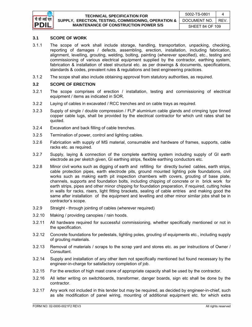
TECHNICAL SPECIFICATION FOR SUPPLY, ERECTION, TESTING, COMMISIONING, OPERATION &
MAINTENANCE OF CONSTRUCTION POWER S/S
5002-TS-0801 4 DOCUMENT NO. REV.
SHEET 84 OF 109
FORM NO: 02-0000-0021F2 REV3 All rights reserved
3.1 SCOPE OF WORK 3.1.1 The scope of work shall include storage, handling, transportation, unpacking, checking,
reporting of damages / defects, assembling, erection, installation, including fabrication, alignment, levelling, grouting, welding, bolting, painting (wherever specified), etc., testing and commissioning of various electrical equipment supplied by the contractor, earthing system, fabrication & installation of steel structural etc. as per drawings & documents, specifications, standards & codes, prevalent rules & regulations and best engineering practices.
3.1.2 The scope shall also include obtaining approval from statutory authorities, as required.
3.2 SCOPE OF ERECTION 3.2.1 The scope comprises of erection / installation, testing and commissioning of electrical
equipment / items as indicated in SOR.
3.2.2 Laying of cables in excavated / RCC trenches and on cable trays as required.
3.2.3 Supply of single / double compression / FLP aluminium cable glands and crimping type tinned copper cable lugs, shall be provided by the electrical contractor for which unit rates shall be quoted.
3.2.4 Excavation and back filling of cable trenches.
3.2.5 Termination of power, control and lighting cables.
3.2.6 Fabrication with supply of MS material, consumable and hardware of frames, supports, cable racks etc. as required.
3.2.7 Supply, laying & connection of the complete earthing system including supply of GI earth electrode as per sketch given, GI earthing strips, flexible earthing conductors etc.
3.2.8 Minor civil works such as digging of earth and refilling for directly buried cables, earth strips, cable protection pipes, earth electrode pits, ground mounted lighting pole foundations, civil works such as making earth pit inspection chambers with covers, grouting of base plate, channels, supports and foundation bolts, including chipping of concrete or in brick work for earth strips, pipes and other minor chipping for foundation preparation, if required, cutting holes in walls for racks, risers, light fitting brackets, sealing of cable entries and making good the same after installation of the equipment and levelling and other minor similar jobs shall be in contractor’s scope.
3.2.9 Straight - through jointing of cables (wherever required)
3.2.10 Making / providing canopies / rain hoods.
3.2.11 All hardware required for successful commissioning, whether specifically mentioned or not in the specification.
3.2.12 Concrete foundations for pedestals, lighting poles, grouting of equipments etc., including supply of grouting materials.
3.2.13 Removal of materials / scraps to the scrap yard and stores etc. as per instructions of Owner / Consultant.
3.2.14 Supply and installation of any other item not specifically mentioned but found necessary by the engineer-in-charge for satisfactory completion of job.
3.2.15 For the erection of high mast crane of appropriate capacity shall be used by the contractor.
3.2.16 All letter writing on switchboards, transformer, danger boards, sign etc shall be done by the contractor.
3.2.17 Any work not included in this tender but may be required, as decided by engineer-in-chief, such as site modification of panel wiring, mounting of additional equipment etc. for which extra
TECHNICAL SPECIFICATION FOR SUPPLY, ERECTION, TESTING, COMMISIONING, OPERATION &
MAINTENANCE OF CONSTRUCTION POWER S/S
5002-TS-0801 4 DOCUMENT NO. REV.
SHEET 85 OF 109
FORM NO: 02-0000-0021F2 REV3 All rights reserved
payment shall be made as per the man-day-rates to be quoted for various categories of workmen.
3.2.18 “AS BUILT” drawings with all site modifications shall be prepared by making the changes on owner’s drawings.
3.2.19 All major civil engineering works pertaining to electrical equipment as per Technical Specification of Civil enclosed elsewhere in the tender.
3.3 EXCLUSIONS 3.3.1 Transportation, handling, assembling, setting, aligning, levelling, plumbing and grouting of all
electrical motors shall be excluded from the contractor’s scope.
3.4 CODES AND STANDARDS 3.4.1 The design, manufacture, testing, installation of the equipment shall comply with the latest
issue of all relevant Indian Standards and codes of practices and all applicable Statutory Acts & Regulations.
3.4.2 The contractor shall have valid “A” class licence from the Director of Electrical Safety to the Govt. of Jharkhand otherwise his offer shall not be considered. The contractor must have PF & ESI codes covering all persons hired by him for carrying out the job.
3.4.3 The contractor shall observe safety rules and take all necessary safety precautions to carry out the work in the plant.
3.5 GENERAL PROCEDURE FOR ERECTION 3.5.1 The general procedure governing "Transfer of equipment and materials to Contractor”, erection
and final acceptance of owner / consultant are given below:
3.5.1.1 Storage of equipment at site
a. All equipment and materials shall be properly stored by the contractor at site in the designated storage area provided by the owner. Contractor shall arrange to draw the necessary equipment / materials in the sequence required for erection and transport the same from contractor's store to erection point.
b. The contractor shall keep proper record of the materials supplied by him / owner.
c. The contractor shall ensure that all the materials drawn / supplied by him are stored indoor / under shade. However, if a package is temporarily stocked outdoor due to unavoidable reasons, this shall be ensured that the storage area is dry, hard and well-drained.
d. Goods must not be placed directly on the floor / ground but shall be kept on blocks, 60 mm to 120 mm above the floor level such that the bottom is well ventilated.
e. In case of outdoor storage, the contractor at his own cost shall provide waterproof PVC sheets/ tarpaulin to cover all goods so as to protect them from rain etc. These sheets / tarpaulin shall be removed for inspection once in a week and if found moist or mouldy, shall be dried in direct sunlight.
f. In addition to the above, the equipment manufacturer's storage instructions, if any, shall be strictly followed.
3.5.1.2 Contractor's inspection at site
b. On receipt of any material (supplied by the contactor) at site, contractor shall fully unpack and inspect all equipment received for completeness, signs of damages, defect etc. in the presence for owner’s representative. Any damage / short supply detected shall be recorded immediately. The contractor shall be required to make good / replace / repair the defective / damaged items at no extra cost to the owner.
TECHNICAL SPECIFICATION FOR SUPPLY, ERECTION, TESTING, COMMISIONING, OPERATION &
MAINTENANCE OF CONSTRUCTION POWER S/S
5002-TS-0801 4 DOCUMENT NO. REV.
SHEET 86 OF 109
FORM NO: 02-0000-0021F2 REV3 All rights reserved
3.5.1.3 Handling and cleaning
a. The contractor shall be responsible for proper handling and cleaning of all materials / equipment drawn / supplied by him until owner / consultant finally accepts the erected equipment.
b. Equipment shall be handled with care by experienced riggers under guidance of competent supervisors and as per rigging marks given on cases. Dragging on floor shall be avoided and crane / suitable rollers shall be used for moving the equipment at any times.
c. The contractor shall be fully responsible for the safe keeping of equipment issued to him till these are erected, tested, commissioned by him and accepted by owner / consultant.
3.5.1.4 Transportation
This involves transportation of various electrical equipments / materials from contractor’s store to erection site. When transporting the equipment, it shall be loaded on suitable trailer / trucks as per capacity and size of equipment, and shall be properly supported on the trailers / trucks by means of ropes / stoppers to avoid damage or tilting due to heavy jerks and vibration. Precautions, if any, displayed on equipment shall be strictly observed.
3.5.1.5 Erection Requirements
a. All work shall be carried out as per drawings supplied. Placing on foundation, aligning, grouting, connecting, fixing danger notice plate / board on equipment as specified, meggering, labelling and painting shall form part of erection requirements.
b. Fixing of supporting frames / pedestals, grouting, cutting and dressing holes in walls / ceiling and any other minor civil work necessary for installation and levelling of electrical equipment are included in electrical erection scope.
c. The scope of erection also includes cable dressing / clamping / minor rerouting, minor relocation of fittings, internal cleaning of equipment, overhauling and minor repairs.
d. Fabrication of clamps from the materials specified and clamping of cables on racks, trays etc. fixing of single core cables in tri-foil formation in aluminium clamps, earthing of cable armour and lead sheath, wherever necessary (and as per the details given by Consultant) fall under erection scope of work.
e. Marking of cables by fixing / grouting the cable marks / number tags at every 25 metres along entire route of cables are included in the scope of work. The tags shall be made of Aluminium Strips.
f. The contractor shall without any extra cost, touch up with paint all electrical equipment which are damaged / scratched during handling, erection or repair. The paint used shall match exactly the painted surface of the equipment on which touch-up is done, and shall be epoxy based.
g. The descriptions given above are only to give a preliminary idea about the scope of work and they do not limit the entire scope to these descriptions only. Hence all other parts of the tender document shall be read in conjunction with the referred standards, associated drawings, specification sheets and schedule of materials & services to assess actual scope of work.
h. The contractor shall undertake erection of all equipment specified herein in accordance with good engineering practices in conformity with statutory regulations and Code of Practice and to the entire satisfaction of the purchaser / owner.
i. The contractor shall arrange all the necessary erection tools, tackles, testing and measuring instruments and shall supply all erection materials as required.
3.5.1.6 Erection Supervision by OEM Suppliers
a. For guiding / supervising erection of sophisticated equipment, services of main equipment supplier’s engineer may be made available free of cost by the contractor for the following
TECHNICAL SPECIFICATION FOR SUPPLY, ERECTION, TESTING, COMMISIONING, OPERATION &
MAINTENANCE OF CONSTRUCTION POWER S/S
5002-TS-0801 4 DOCUMENT NO. REV.
SHEET 87 OF 109
FORM NO: 02-0000-0021F2 REV3 All rights reserved
equipment. However, this will neither absolve the contractor from his responsibility nor his obligation to provide his own supervisors or technical personnel.
• 33 KV RMU / 3.3 KV panels, Soft starter panel etc.
• Power transformer
• HT motor (Testing and commissioning)
b. The contractor shall have to comply with all the directions of Engineer-in-Charge, drawings etc. issued to him within the scope of his contract by supplier’s engineer.
3.6 SPECIFICATION FOR ELECTRICAL ERECTION 3.6.1 General 3.6.1.1 These specifications lay down the erection procedures to be followed for each type of
equipment, over and above the general "Erection Requirements".
3.6.1.2 The contractor shall also follow manufacturer’s instructions and any other instructions of consultant / Principal / Statutory bodies during erection.
3.6.1.3 Suggestive Erection Drawings shall be supplied to the successful bidder for Lighting, Earthing, Cable Tray Routing, etc. These drawings may be suitably modified, if required, to suit site requirement with the approval of owner / consultant.
3.6.1.4 As-Built Drawings shall be prepared by the bidder and supplied to owner/ consultant.
3.6.2 Switch Boards/RMU
3.6.2.1 Handling
a. As far as possible lifting of switchboards shall be done by making use of eyebolts provided. It shall be ensured that before lifting, all eyebolts are fully tightened and that panel supports, nuts and bolts are intact and tight.
b. If lifting arrangement is not provided / not feasible and final positioning by sliding is unavoidable, packing base shall be retained as long as possible and rolled on suitable pipes. Dragging of panel directly on floor by crowbars shall be avoided.
c. Maximum care shall be taken to avoid any damage to insulator, bushings, meters and protective equipment.
3.6.2.2 Erection
a. Check the foundation according to the drawings. Ensure that all pockets have been rightly made. Fix the datum level, and level the foundation by chipping in such a way that the prescribed point of cubicle base plate is flushed with finished floor.
b. Check the individual cubicle for any deformity and ensure that all faces are straight. Any dent on sheet steel frame shall be rectified before placing on foundation.
c. Wherever separate base frames are supplied, level the foundations in both directions (lateral and transverse) and ensure that these have been correctly levelled throughout. In case of runner rails, check the rails for level in both the directions and ensure that they are parallel to each other. Wherever base frame is fixed to cubicle, place the cubicle on foundation ensuring that holding down bolts are directly over the foundation pockets.
d. Obtain correct level of panel with respect to floor / existing bus-bar by putting shims below base frame, shims are to be supplied by the contractor. Measure the level of each frame with reference to datum and ensure that level difference between the two ends of the switchboard base frame is within ± 2 mm.
e. Cubicle shall be so adjusted that front face of all the panels are in one plane, all sides are plumb and corresponding horizontals on all panel faces (e.g. minimum lines, door edges, inter

TECHNICAL SPECIFICATION FOR SUPPLY, ERECTION, TESTING, COMMISIONING, OPERATION &
MAINTENANCE OF CONSTRUCTION POWER S/S
5002-TS-0801 4 DOCUMENT NO. REV.
SHEET 88 OF 109
FORM NO: 02-0000-0021F2 REV3 All rights reserved
cubicle joints) line up in the same horizontal line (s). Match the cubicles and adjust properly. Provide gasket between edges, if required; so that no inter-panel gaps are seen.
f. Bolt adjacent cubicles and base frame together by drilling new holes, wherever necessary to match holes.
g. Grout the foundation bolts with mortar, run grouting mixture under base of the cubicle frame, ram to ensure solidity. After grout has set properly, tighten the foundation bolts.
3.6.2.3 Bus Connections and Installation of Loose items
a. Fix bus bar links and inter panel bus-bar connections with coupling bolts / supporting insulators. Clean the contact surface of bus bars and links and smear with contact grease before bolting.
b. Wherever recommended, fix shroud on the joints and fill compound, or compound may be put on joint to form smooth homogenous & spherical shaped mass and then wrapped with tape. Simple taping of joints may also be done. Recommendation of manufacturer / consultant / Principal shall be followed in this respect.
c. In case of misalignment of bus bars, adjustments may be necessary. The connecting pieces may have to be re-drilled or re-fabricated.
d. Check tightness of bus bars bolts connections with torque wrench. Follow vendor's recommendations in this regard.
e. Install all loose relays, instruments, cable boxes, metering and protective CTs, PTs etc. Before fixing the relays, make sure that they are cleaned and all packing materials have been removed from them and proper operation. Clean the contacts.
f. Connect all inter-panel bus wiring. Connections of relays and instruments shall be done as per drawings. Check the wiring according to wiring diagram.
g. Connect all earthing bus bar between the cubicles and it shall be connected at two points by Al / GI strip or cable to the main earthing ring. Fix all glands for incoming and outgoing and control cable connections on the holes provided for the purpose, as per drawings.
h. Drill holes for fixing cable glands / cable boxes as per drawings, if such holes are not provided. All spare holes, gaps etc. shall be blanked as per instructions of Principal / Consultant.
3.6.2.4 Cleaning
After erection is complete all cubicles, switches, starters, CTs, PT Chambers, Bus bar Chambers etc. should be cleaned by blowing air (preferably hot air). Surface of the insulation shall be cleaned with cloth soaked in CTC / Benzene.
3.6.2.5 Circuit breakers installation (Air Circuit Breaker)
a. Clean the contacts properly with cloth soaked in CTC / Benzene etc. Clean and lubricate the operating mechanism, check and rectify the main insolating contacts and bushings and also secondary contact for any damage / misalignment. Check the locking mechanism.
b. Manually close and trip the breaker several times and check contact alignment and pressure. Adjustment, if required, shall be done according to the manufacturer's instruction. The arc chute if despatched separately should be fixed properly, only after checking of contact alignment etc. After fixing the Arc Chute, operate manually the breaker and check the contacts make properly. Measure contact resistance with conductor. Check the operation of OFF-ON indicator.
3.6.2.6 General Checks
a. Ensure that all gaskets are in position, replace the same if found damaged.
b. All opening covers and rear doors shall be bolted with required number of bolts. Take care that no bolt/nut/ washer gets lost during handling and erection.
TECHNICAL SPECIFICATION FOR SUPPLY, ERECTION, TESTING, COMMISIONING, OPERATION &
MAINTENANCE OF CONSTRUCTION POWER S/S
5002-TS-0801 4 DOCUMENT NO. REV.
SHEET 89 OF 109
FORM NO: 02-0000-0021F2 REV3 All rights reserved
c. Check inter-changeability of breakers of same rating.
3.6.3 Transformer 3.6.3.1 Handling
a. Transformers shall be lifted by lugs or shackles provided for the purpose to avoid unbalance while lifting.
b. It shall be ensured that Lifting chains / slings do not interfere with any part of the transformer.
c. Cover bolts shall be checked for tightness. If found loose, it shall be tightened fully before handling. Care shall be taken that the bolt does not rotate to avoid damage of the gasket.
d. Jacks shall be used, if required, only on jacking pads provided for the purpose (jacks shall never be used under valves or radiators tubes).
e. Transformer shall never be left without putting stoppers of the wheels.
3.6.3.2 Erection
a. Foundation of the transformer shall be prepared and checked for its level as per Drg. before shifting / transferring the transformers from the stores.
b. Proper time shall be given for curing the level of rails.
c. Wheels shall be fixed before placing of the transformer in position. Wheels of the transformers shall be checked for its proper movement. Greasing shall also be done on the shaft of wheel before placing the wheels in position. Split pins must be used / placed in position before its rolling.
d. Transformer shall be placed on the prepared foundation only.
e. Transformer’s wheels shall be checked for its free movement on the rails/ plates. It shall be then levelled & aligned with the bus ducts, which shall be connected on the LT side of the transformer.
f. Stoppers to the transformer wheels shall be provided immediately after alignment to prevent any movement.
g. Cleaning of all the accessories like radiators, cooling fans, valves, conservator tank, explosion vent pipe, bushings and other accessories shall be done.
h. Radiators shall be flushed with hot oil before assembly.
i. Cloth only shall be used for cleaning purposes.
CAUTION: While working on the transformers with hand-holes or bushing holes, take care that no tools or any other foreign matters are dropped into the tanks. All the loose tools shall be properly tied and secured.
j. All accessories such as radiators, conservator, valves, explosion vent pipe, Buchholz relay, HV and LV bushings, cable end termination boxes, marshalling box, instruments, capillary tubes, silica gel breather with dried silica gel, fans etc. shall be assembled as per vendor’s drawings and instructions.
k. Operation of shut off valves and tightness of all gasket joints shall be checked before topping up of oil. Thermometers shall also be fixed.
l. Oil samples from each drum for dielectric strength shall be tested. Oil with standing 40 KV for 1 minute shall only be filled.
m. Oil shall be filtered with filtering machine by using metallic hose.
n. Bottom drain valve shall be used to fill oil in the transformer tank to prevent aeration in oil.
TECHNICAL SPECIFICATION FOR SUPPLY, ERECTION, TESTING, COMMISIONING, OPERATION &
MAINTENANCE OF CONSTRUCTION POWER S/S
5002-TS-0801 4 DOCUMENT NO. REV.
SHEET 90 OF 109
FORM NO: 02-0000-0021F2 REV3 All rights reserved
o. It shall be ensured during oil filling operation that no air pockets are left in the tank and no dust or moisture enters the oil. All air vents shall be opened. Oil flow rate shall be reduced when oil level is almost upto the bottom of the main cover to prevent internal pressure form rupturing the diaphragm of pressure relief pipe. Sufficient time shall be allowed to escape all air bubbles. Air bubble accumulated in Buchholz relay shall be released by opening air release cock provided on the top. Vent plugs shall be closed.
p. Cables shall be connected to HV and LV terminals of transformer.
q. Control cables / power cables shall be connected to Marshalling Box. Stop push button mounted on the wall of transformer room shall be connected to trip the transformer.
r. Transformer body shall be earthed at two separate points to main earthing strip.
s. Transformer neutral shall be earthed to a separate and distinct neutral earth pit (through NER, wherever applicable) as per design and drawings.
t. Danger notice board conforming to IS: 2551 and IE Rules 1956 shall be provided on enclosure or door of the enclosure.
u. Transformer Room’s door / enclosures shall be earthed as per IE Rules, 1956.
v. Safety items i.e. fire extinguishers, shock treatment chart, fire buckets with screened sand etc. shall be provided.
3.6.4 Cable Installation
3.6.4.1 General
a. All fabrication, cutting, laying, spacing, fixing etc. of cables, trays, supports, hangers etc. shall be as per drawings and instructions of Owner / Engineer-in-Charge.
b. The contractor shall keep accurate record of cable drums supplied by owner, the drum nos. and actual length of cable taken out of each drum. Each cable length shall be cut from a specific drum as per approved schedule of cable. Lengths of cable runs shown in the cable schedule are calculated lengths only, hence the actual lengths shall be measured at site before laying and cutting the cable. The contractor shall take extreme care to adjust cable runs from drums so that joints in the cable are avoided and wastage reduced to minimum.
c. For purpose of measurement of cable run for payment the length of cable between and terminations only shall be considered.
3.6.4.2 Laying
a. The cable drums should be properly mounted on jack / cable wheel. Make sure that the spindle is suitable for carrying weight of the drum without bending. Check that spindle is laying horizontal on the bearing so as to prevent the drum creeping to one side or to the other while rotating.
b. Unroll the cables from the drum in correct direction. Rotate drum only as per arrow mark given in the cable drum. Ensure that the end protection box attached to the flange of the drum is removed and securing rope cut to allow cable and move freely. Rotate the cable drum and simultaneously pull cable steadily and with even pulls and not with unnecessary jerk or strain. In no case the cable shall be allowed to twist or kink since this is likely to spring the armour and fracture the insulation and outer serving of the cable.
c. Do not drag the cable on floor or hard surface. Use only wooden / steel cable rollers for this purpose.
d. Cable should not be bent sharply to a small radius. The cable bending radius shall be as large as possible and will not be less than 15 times the outside diameter for XLPE cables and 12 times for PVC cables. At joint termination the individual core of cable shall not be bent with bending radius of less than 15 times the diameter over the insulation.
TECHNICAL SPECIFICATION FOR SUPPLY, ERECTION, TESTING, COMMISIONING, OPERATION &
MAINTENANCE OF CONSTRUCTION POWER S/S
5002-TS-0801 4 DOCUMENT NO. REV.
SHEET 91 OF 109
FORM NO: 02-0000-0021F2 REV3 All rights reserved
e. Where cables are laid on the MS racks, trays etc. ensure that trays / racks / supports are fixed properly in an approved manner or according to the drawings. Check from drawings that for horizontal runs of cable, bracket, risers, supports, angles are grouted or fixed in formation as required.
f. In sub-station where large no. of cables rise to panels/ switchboards, it shall be ensured that these risers do not interfere with cables on racks and rising cables do not interfere with cables on racks and rising cables do not cross the other cables in horizontal runs. Risers are to be properly supported so that weight of cable does not fall on terminations. All cable crossings shall be avoided.
g. Cable laid in trenches should be sealed at the entry to hazardous area / non-hazardous area as per direction of owner / engineer-in-charge.
h. Openings in substation basement and floors for entry of cables shall be sealed after the cables are laid.
i. Cables shall be clamped by taking care to be taken to space clamps at such intervals as to prevent buckling of cables.
j. The laying of the cable on the racks shall be done in an approved manner and according to the drawings supplied.
k. Where cables are laid in cable slits, the slits after laying of cables shall be filled with sand & lean cement mixture and plastered so that surface flushes with top of slit.
3.6.4.3 Directly Buried Cables
a. Laying of under ground directly buried cables shall include excavation of earth along the cable route, laying of Hume / GI pipes for road crossing, back filling, ramming, removing of extra earth including supply of bricks, sand etc. as per drawing and instruction of Owner / Engineer-in-Charge.
b. Where cables are directly laid into ground, trenches should be dug up to such a depth as to ensure that the depth of the top of the entire cable below the ground level is min. 750 mm for medium and low voltage cables, and min.1050 mm for high voltage cables. Before laying of cables at these trenches, bottom of the trench should be properly levelled up and all odd and sharp materials removed. Trench bottom then should be bedded with a 75 mm thick layer of sand. Approval of Owner / Engineer-in-Charge shall be taken for preparation of this bed before laying of cables. Cables shall be laid in the trenches in straight runs. Care shall be taken so that any kinds or bends are not formed. After laying of the cables, bricks shall be placed length wise on both the sides of the cables along the entire length to form trough.
c. Fill up space between bricks with sand up to height of the bricks. Then place bricks closely width wise on top of the sand layer throughout the length. Fill up loose earth in trench, ram properly to compact, remove extra earth from site. Broken bricks shall not be use for brick working. Only Class-I bricks shall be used.
d. If new cables are laid to cross existing cables, the new cable shall be laid under existing cables at depth of not less than 200 mm from the existing cable. It shall be ensured that the approach of new cable to the crossing is uniform and gradually sloped.
e. Fix cable markers at 100 Mtrs. apart and at joints on the entire cable route length of the cables. The cable markers shall be made of pre-cast concrete blocks of 300 mm x 350 mm x 350 mm size with markings of “HT CABLE”, “LT CABLE”, “Depth of Cable”, “Arrow Marks” etc. inscribed. These shall be supplied by the contractor at no extra cost and fixed as per directions of the Owner / Engineer-in-Charge. The top of the above concrete slabs shall have a smooth finish with cement only.
TECHNICAL SPECIFICATION FOR SUPPLY, ERECTION, TESTING, COMMISIONING, OPERATION &
MAINTENANCE OF CONSTRUCTION POWER S/S
5002-TS-0801 4 DOCUMENT NO. REV.
SHEET 92 OF 109
FORM NO: 02-0000-0021F2 REV3 All rights reserved
f. Laying of cables under road crossings etc. shall be done in pipes, and pipe ends shall be sealed with bitumen compound and sand as required after cables are laid. Backfilled soil shall be rammed thoroughly to prevent road surface cracking due to settlement of loose soil.
3.6.4.4 Laying in Readymade Trenches
a. RCC slabs / chequered plates lifted from trenches for laying cables shall be put back in position at close of work every day to avoid accident & damage to cables in the trench.
b. When cables pass through pipes, pipe ends shall be sealed with bitumen compound and sand as required.
c. Protection pipes shall be provided, whenever cables enter from the floor, trench etc. in the equipment and sealing in and around these pipes shall be done.
3.6.5 Cable Jointing and Termination
3.6.5.1 General
The scope of work shall include but not limited to the followings:
a. Soldering / crimping of sockets / ferrules and connections at all joints/ terminations as per specifications. Sockets shall be provided at all terminations except where pressure clamp type terminals are provided.
b. Glanding of cable and fixing of cable boxes.
3.6.5.2 Specifications
a. HT XLPE cables shall be terminated by use of heat shrink type termination kits.
b. All LT XLPE power and control cables shall be terminated through compression type gland.
c. In case of LT XLPE cables, armours shall be suitably earthed in compression type glands. For HT XLPE cables, this shall be done either in glands or by any other suitable means like bonding the armour with suitable wire and connecting same to the earth terminals inside cable box.
d. In explosion proof equipment, sealing accessories, where provided in cable box, shall be used for sealing the cable entry to the box and termination.
e. All lighting and control cables shall be provided with crimped Al / Cu Sockets before termination in junction boxes.
3.6.5.3 Crimping
a. For all power cables, crimping type Al lugs for Al cables and tinned Cu lugs for Cu cables shall be provided. These lugs shall be crimped on the cable conductors by means of special hand/ hydraulic crimping tools. Before crimping the socket inhibiting grease shall be smeared over the conductor. Conductor shall be shaped properly before sliding the socket over it. Crimping shall be done in an approved manner.
b. All the control cables, which shall be of copper conductor, shall be terminated without any additional lugs in screwed type terminals provided in various equipments.
3.6.5.4 Jointing
a. The jointing shall be done in an approved manner. Care shall be taken not to damage the insulation when opening the cable for jointing.
b. Before commencing soldering of the socket, conductor shall be thoroughly cleaned and insulation protected. The ferrules shall be thoroughly cleaned. Ferrule and each strand of the cable shall be thoroughly sweated with solder to tin them and fill the conductor gaps to remove all air pockets. Soldering materials of approved quality as per ISS practice shall be used. Taping of the conductors shall be done in an approved manner after crimping / soldering.

TECHNICAL SPECIFICATION FOR SUPPLY, ERECTION, TESTING, COMMISIONING, OPERATION &
MAINTENANCE OF CONSTRUCTION POWER S/S
5002-TS-0801 4 DOCUMENT NO. REV.
SHEET 93 OF 109
FORM NO: 02-0000-0021F2 REV3 All rights reserved
c. Filling up compound and sealing the cable box shall never be done in one operation. After the first pouring of compound, it should be topped up again with compound and then sealed.
3.6.5.5 STRAIGHT THROUGH JOINTS
a. Jointing of XLPE & XLPE cables shall be done with extreme care and manufacturer’s instructions shall be strictly followed. Soldering of sockets shall also be done with extreme care as indicated above.
Earth continuity wire shall be plumbed and / or clamped. Compound shall be filled according to the instructions of manufacturers of terminating kit / cable. Joints made inside trench or on rack shall be properly supported. Wherever joints are made inside ground, brick masonry work shall be done around the joint box and filled with sand, and there after covered with earth at no extra cost.
b. A tent shall be used in all circumstances where jointing work is being done outdoor, for protection against rain and to prevent dust from being blown in to exposed joints and jointing materials. Extreme care shall be taken to maintain proper phase sequence while terminating at equipment ends. Records of connection details shall be maintained. Conductors shall be shaped properly while terminating and no sharp bends shall be given. Where numbers of cables are to be connected in parallel, proper tests shall be done before connection, so that no cross connection shall be made. No phase crossings shall be allowed for making the connections.
c. Cables shall be supported adequately at the entry to cable box / equipment so that load of cable does not come on cable glands.
d. All cables shall be meggered before and after jointing and insulation values recorded.
e. While terminating at equipment end, each core shall be properly tagged with numbering ferrules as per nomenclature given in the drawings. Wires should be dressed and clamped neatly, bolting shall be done properly.
3.6.6 Earthing
3.6.6.1 General
a. Painting of all earth strip joints with anti-corrosive paints shall be carried out as per details given in drawings and instruction of Owner / Engineer-in-Charge.
b. All electrical equipment rated 415 V and above shall be connected to earth bus by two separate and distinct earth connections. All equipment rated 240 V and below shall be earthed with single earth conductor.
3.6.6.2 Specifications
a. Types and sizes of earthing conductors shall be as indicated in the SOR attached. All earthing installations shall conform to IS-3043.
b. Underground conductors shall run at a depth of 600 mm below ground level. Where these conductors run along with cables, they shall be laid at the same depth as cables. Where conductors run on wall, ceilings, they shall be laid on clamps or brackets made out of Al/GI strips.
c. Wherever, earthing conductor is passing through floor, walls etc. the conductor shall be taken through PVC / GI pipes.
d. All paints, enamel etc. shall be removed from point of contact before making connections.
e. Connections between G.l. strips shall be done by welding. For connecting Al conductor / G.I. wire, Al socket shall be crimped on the conductor / wire. At the equipment end, connections shall be done by bolting.
TECHNICAL SPECIFICATION FOR SUPPLY, ERECTION, TESTING, COMMISIONING, OPERATION &
MAINTENANCE OF CONSTRUCTION POWER S/S
5002-TS-0801 4 DOCUMENT NO. REV.
SHEET 94 OF 109
FORM NO: 02-0000-0021F2 REV3 All rights reserved
f. Connection between Al & GI shall be done by bolting. Graphite grease shall be applied on contact surfaces.
g. Epoxy resin paint or bitumen shall be applied on welded or bolted joints to prevent corrosion and taping done as indicated in the drawing. Connections between Al wires shall be done by crimping back to back Al ferrule.
h. Earth electrodes - Earth electrodes shall be provided as per drawings / specification. Work includes excavation of earth, installation of electrodes and test links etc., supply and filling of charcoal and common salt, back filling of earth and removal of extra earth as specified earlier. It also includes making brick wall around the electrode and cover as per drawings / specifications. The testing links shall be grouted on brick wall and connections with earth electrode and conductors shall be made. Distance between two electrodes shall not be less than 10 meters and may be located 4 M away from building foundation.
i. Earth pits for equipment earthing, neutral earthing and lightning protection shall be separate. However, these pits shall be inter-connected.
3.6.7 Plant Lighting
3.6.7.1 The electrical installation covered by this specification shall conform to relevant Indian Standards & codes of practices.
3.6.7.2 Erection of light fittings, plug sockets etc.
Fabrication of supports for lighting fittings, sockets, junction boxes shall be done as per the relevant drawings / instructions given by the owner / engineer-in-charge. These shall be grouted to walls, ceiling or welded to insert plates, steel structures etc. Insert plates on ceilings shall normally be provided. However, if required, the contractor shall weld such supports to the reinforcement rods after exposing by chipping off concrete at no extra cost. Installation of lighting fittings includes control boxes, where supplied separately and shall be done as per drawings. Before installation, checking of internal parts, assembly of accessories shall be done as per manufacturer's instruction.
3.6.7.3 The explosion-proof fittings shall be earthed through third core of the cable used for wiring. The third pin and body of 15 amps shall be earthed similarly.
3.6.7.4 Installation of explosion proof equipment shall be done strictly following manufacturer's instruction or relevant Standards. Cable termination shall be done as per relevant drawings. No drilling of holes or any change in construction of equipment or part thereof shall be done.
3.6.7.5 Wiring for normal AC supply light points and plugs shall be taken on the same brackets but wiring for emergency DC supply lights shall be taken separately. Drawings for lighting layout give only tentative location of fittings and wiring route shall be decided in consultation with owner / engineer-in-charge. Wiring shall follow shortest possible route and no. of circuit shall be bunched together to the extent possible in the same route. For wiring and laying of cables, Cl. 3.6.4 shall be referred.
3.6.7.6 Cable for wiring light points and socket outlets shall normally be laid along wall, ceilings, structures, on suitable brackets made out of M.S. / Al sheets or strips. Connections to the points with fluorescent fixtures in one circuit shall be taken through junction boxes. Junction boxes shall be suitably located for branching off from the circuit to the individual point. Wherever indicated, cables may be laid directly on walls, ceilings etc. by clamping on saddles.
3.6.7.7 Terminations shall be done in a manner as detailed in Cl. 3.6.5. Wherever indicated, the wire can be drawn through PVC bushings provided in the fittings. Relevant drawings may also be referred to.
3.6.7.8 Lamps shall be installed after installation of fittings and wirings.
3.6.7.9 All light fittings and corresponding control switches shall be numbered in a permanent way as instructed by owner / engineer-in-charge.

TECHNICAL SPECIFICATION FOR SUPPLY, ERECTION, TESTING, COMMISIONING, OPERATION &
MAINTENANCE OF CONSTRUCTION POWER S/S
5002-TS-0801 4 DOCUMENT NO. REV.
SHEET 95 OF 109
FORM NO: 02-0000-0021F2 REV3 All rights reserved
3.6.8 ERECTION OF STRUCTURES
3.6.8.1 Specification
The fabrication work shall be done as per drawings / specifications / sketches in an approved manner and to the entire satisfaction of owner / engineer-in-charge. The contractor shall take adequate measures to avoid wastage. Scrap quantity shall not exceed 2 % of total quantity used for erection.
3.6.8.2 Erection of racks, risers, supports etc.
a. Erection of racks and risers for cable supports shall be done along the cable routes as indicated in the drawings. The contractor before erection shall check the route for any obstruction like process pipe lines, structures, equipment etc. In case of obstructions, the matter shall be brought to the notice of owner / engineer-in-charge in writing and racks shall be re-routed as per his instructions.
b. As and where indicated in the drawings, supports for racks, risers etc. shall be welded on the steel structure, such as MS beams, pipe trestles, insert plates provided in the RCC column etc. for erection of racks.
c. Wherever indicated, supports for racks, risers, shall be grouted on walls. The racks, risers etc. shall be installed on such supports and those properly welded.
d. Opening on walls / floors shall be provided where racks / risers are crossing floors/ walls.
e. Heavy channels, risers may also be grouted on the floors in addition to supports provided from walls, ceilings, steel structures etc.
f. As indicated in the drawings, racks and risers shall be erected either in single tier/ multi tier formation.
3.6.8.3 Erection of supports in trench
a. Supports and Hangers shall be grouted with rag bolts on the walls of readymade concrete trench.
b. In existing trench wall, contractor may be required to provide pockets for grouting cable supports at some points. This shall be done without any extra cost to the owner.
c. In case of requirement of insert plates for support of cable rack, the contractor shall weld such plates to the reinforcement MS rods. This shall be done by chipping the concrete for exposing the reinforcement MS rods and thereafter welding the plates and making good the concrete chipping by plastering.
3.6.8.4 The pipes will have to be bent (wherever required) and fixed / embedded in floor, wall and ground for laying the cables. Neoprene bushes shall have to be fixed at the end of such pipes.
3.6.8.5 GI trays of different sizes shall be cut in size and fixed on racks and risers. Fixing of trays shall only be done after erection / welding / painting of the supports as required.
3.6.8.6 Erection of support frames for miscellaneous equipments, base channels for transformers and switchboards etc. shall be carried out at no extra cost.
3.6.8.7 Dismantling of steel fabrication and re-erecting as required by owner / engineer-in-charge shall have to be carried out by the contractor.
3.6.8.8 Dismantling of cable racks and re-erecting as required by owner / engineer in charge shall be carried out by the contractor.
3.7 GENERAL PROCEDURE FOR TESTING & COMMISSIONING
3.7.1 Before proceeding with the work, contractor shall fully inspect all installed Electrical Equipment for completeness, signs of damages, defects etc. and record all discrepancies noticed. The
TECHNICAL SPECIFICATION FOR SUPPLY, ERECTION, TESTING, COMMISIONING, OPERATION &
MAINTENANCE OF CONSTRUCTION POWER S/S
5002-TS-0801 4 DOCUMENT NO. REV.
SHEET 96 OF 109
FORM NO: 02-0000-0021F2 REV3 All rights reserved
contractor shall be required to make good / repair / replace the damaged components at no extra cost.
3.7.2 Testing and Commissioning Requirements
a. All works shall be carried out in accordance with the drawings, supplier’s instructions / manuals for equipment and as per relevant ISS & Code of Practices.
b. Before conducting test on any equipment, the contractor shall obtain permission from owner / engineer-in-charge and all tests shall be conducted in their presence.
c. Results of each test shall be recorded by the contractor immediately after the test on approved performa and counter signed by the owner’s authorised representative. The test results shall be furnished in four copies in the form of ‘Test Certificates’. Performa for some of the items are given in Appendix-1.
d. Copies of the record shall be handed over to owner / engineer-in-charge.
e. The Contractor shall commission all electrical equipment and carry out all pre-commissioning / commissioning tests inclusive of no-load and on-load tests on motors, and shall be responsible for final adjustments of relays, motors, instruments, starters, breakers etc. as per operational data supplied and as per directions of Engineer-in-Charge.
f. All terminals, cable joints, earth terminals which are opened for testing purposes shall be re-terminated and re-insulated by the Contractor to restore their original state.
g. Painting
The contractor shall without any extra cost, touch up with paint all electrical equipment which are damaged/ scratched during testing and commissioning work. The paint used shall match exactly painted surface of the equipment on which touch up is done.
3.7.3 Cleaning and Regular Maintenance.
Till the commissioned equipment is finally accepted by owner / engineer-in-charge, Contractor shall be responsible for regular cleaning and maintenance of all electrical equipment. The maintenance job is to be done in consultation with or on advice from the Owner/ Consultant.
3.8 TESTING & COMMISSIONING SPECIFICATIONS
3.8.1 These specifications lay down the testing and commissioning procedures to be followed for each type of equipment, over and above the general requirements laid down in specifications for erection.
Manufacturer's instructions and any other instructions of owner / engineer-in-charge / statutory bodies shall also be followed by the contractor during testing and commissioning.
The contractor shall maintain and furnish the records of all equipments i.e. HT/LT panels, motors, transformers, CT, PT, relays etc. including any special test as per manufacturer’s manual.
3.8.2 Switch Boards/RMU
3.8.2.1 General Checks
a. Check all auxiliary contacts of breakers for proper make / break operation.
b. If necessary, make minor adjustments to circuit breakers mechanism, auxiliary contacts etc. for proper operation of circuit breakers. Proper greasing and lubrication or mechanism shall also be done before final commissioning.
c. Check for termination of control circuit wiring as per drawing and ensure that the terminals at equipment and panel are mechanically sound.
d. Ensure proper operation of all test operation switches and push button.

TECHNICAL SPECIFICATION FOR SUPPLY, ERECTION, TESTING, COMMISIONING, OPERATION &
MAINTENANCE OF CONSTRUCTION POWER S/S
5002-TS-0801 4 DOCUMENT NO. REV.
SHEET 97 OF 109
FORM NO: 02-0000-0021F2 REV3 All rights reserved
e. Contractor to arrange primary injection kit for testing of incomer breaker (rated at 3200A).
f. Check wiring of all space heaters, indication lamps bells, buzzers etc.
3.8.2.2 Insulation resistance test
a. Measure the insulation resistance of main bus-bars (Phase to phase & Phase to earth) and circuit breaker with 1000 V Megger (IR values shall generally be not less than 100 MΩ for 33 KV, 50 MΩ for 3.3 KV, 10 MΩ for 415 V).
b. Control wiring shall be tested with 500 V Megger (IR values shall not be less than 2 MΩ).
3.8.2.3 High Voltage Test
The test shall be conducted contacted on switch Gear rated 3.3. KV and above.Test shall be as per relevant Indian Standard. However, for AC high voltage test the value shall be twice the working voltage of the switchgear plus 1000V. This voltage shall be maintained for 1 minute. Each phase shall be tested in turn with remaining phases earthed. After high voltage test, a further megger test shall be made to make sure that insulation resistance to earth has not altered appreciably. The reading of second megger test should be consistent with that of the first. (AC test voltage for 1 min. duration shall be 67KV for 33 KV panel and 8 KV for 3.3 KV panel).
3.8.2.4 Testing of Current Transformer
a. Insulation resistance to earth of secondary winding shall be tested with 500 V megger (remove earth connection before test).
b. Check the polarity of C.T:- Connect zero centre voltmeter in the secondary winding, connect 6 V battery with switch in the primary, close the switch and from the kick of the voltmeter, ascertain the polarity.
3.8.2.5 Testing of P.T. Insulation
Testing of H.T. & LT side of P.T. shall be done with 1000 Volts and 500 Volts megger respectively (the value shall not be less than 100 MΩ and 2 MΩ respectively).
3.8.2.6 Testing of Relays
1.0 Checking of wiring shall be done according to Manufacturer's drawings. Check relay continuity at all taps and also ensure plug bridge contact satisfactory.
2.0 Secondary injection test
Use secondary injection test set incorporating timer. Testing of all protective relays such as but not limited to over current, earth fault, differential, motor protection, under voltage relays etc. shall be done as per the procedure set by the manufacturers of the relays. All time delay relays shall be tested to verify their characteristics for IDMT and instantaneous relay pick up and drop off values shall be noted at various taps. Relays shall be tested at all taps. Errors shall be calculated and compared with permissible limits specified by manufacturers. Adjustment, such as in establishing circuit, shall be done as recommended by manufacturer. After testing, relays shall be set at values given by Consultant.
3.0 Timer relay shall be tested and calibrated and set properly.
4.0 All auxiliary relays shall be tested for proper operation.
3.8.2.7 Testing of Instruments
All indicating and recording instruments like Ammeter, Voltage meter, KWh meter etc. shall be calibrated. Zero error of each instrument shall be corrected.

TECHNICAL SPECIFICATION FOR SUPPLY, ERECTION, TESTING, COMMISIONING, OPERATION &
MAINTENANCE OF CONSTRUCTION POWER S/S
5002-TS-0801 4 DOCUMENT NO. REV.
SHEET 98 OF 109
FORM NO: 02-0000-0021F2 REV3 All rights reserved
3.8.2.8 Operational Test
Conduct the following operational tests after putting the circuit breaker at test and service position. Check that the fuses of proper rating are put in control circuit as per wiring diagram.
a. Close and trip the circuit breaker several times with power or manually. In case of motor operated spring charged closing mechanism, check the operation of charging motor. Ensure that it cuts in/ off properly.
b. Check the indication scheme ON, OFF, trip circuit healthy, auto-trip etc.
c. Trip the breaker by operating the protective relays (operate contact manually).
d. Check the trip free feature
e. Check the anti-pumping feature
f. Check operation of voltage selector relay scheme for supply.
g. Check annunciation scheme for AC / DC power supply failure.
h. Each motor starter shall be tested for correct operation. All operational tests to verify sequence of operation, inter-locking, alarm indication schemes (by simulating the connection) shall be done.
i. Bi-metallic type thermal over load relay shall be tested at different settings. Current shall be injected through the thermal elements (three elements can be connected in series) at twice and thrice the set value and tripping time shall be noted. The values shall be compared with the data supplied by manufacturer.
j. Single phase prevention relays shall be tested for proper operation.
k. Check that fuses of specified ratings are put in various outlets.
3.8.3 Transformer 3.8.3.1 Final testing before commissioning shall be done in cold condition after drying out the
transformer and disconnecting H.V. and L.V. side cables by removing link in disconnecting chamber, cables and also earth connections to neutral.
3.8.3.2 At least 1000 Volt megger shall be used for 33 KV winding and manufacturer’s test certificates shall be compared for the purpose. 500 Volt megger shall be used for auxiliary power cables and control cable and values shall be preferably more than 2 MΩ.
Polarization Index shall be recorded as below to determine whether drying is necessary or not:-
Min1IRMin 10 IRPI =
Evaluation of insulation Base Drying condition based on PI on PI ------------------------------------------ --------- ----------
Hazardous < 1 Mandatory Bad 1-1.5 Mandatory Doubtful 1.5 - 2 Recommended Adequate 2 - 3 No Good 3 - 4 No Excellent > 4 No
3.8.3.3 Oil Tests
a. Crackle Test: Cleaned Iron piece shall be heated red hot and put in the oil taken in a pot. In case of crackle sound, presence of moisture is indicated.
TECHNICAL SPECIFICATION FOR SUPPLY, ERECTION, TESTING, COMMISIONING, OPERATION &
MAINTENANCE OF CONSTRUCTION POWER S/S
5002-TS-0801 4 DOCUMENT NO. REV.
SHEET 99 OF 109
FORM NO: 02-0000-0021F2 REV3 All rights reserved
b. Dielectric Strength Test: It shall be done as prescribed in Appendix ‘C’ of IS: 335. The oil should withstand minimum of 40 KV for 1 minute.
Even oil conditions are found satisfactory in testing after final topping. It is advisable that as an additional precaution, the transformers shall be dried out.
3.8.3.4 Drying out Procedure
a. Drying out of the transformers shall be carried out in accordance with IS: 10028.
Before drying out following points shall be checked:-
− Any oil leakage through bushings and radiators
− Transformer tank is connected to the earth
− Temperature indicators are suitably calibrated and connected
b. Precautions when drying :-
Maximum sustained temperature shall not be more than 80OC. Do not leave the transformer unattended during drying out period. Watch the transformer during drying out process and record carefully all observations viz. Oil temperature, winding temperature and insulation resistance of H.V. and L.V. windings. Drying out shall be continued till the insulation resistance value is steady prescribed in Standard Code of practice and IS: 10028 Part-II and steady value remains constant for 12 hours. Within the above period, several samples of oil are to be tested to ascertain dielectric strength. All readings shall be recorded (hourly/ half hourly) for insulation resistance and temperature of oil and winding. Sample of transformer oil shall be collected from bottom only. The oil shall be allowed to settle for at least 24 hrs.
In case the insulation value does not improve by the above method, low voltage equal to impedance voltage shall be supplied to HV side for few hours after short-circuiting the LV side. During the process, regular readings of insulation resistance of winding to earth, winding to winding and temperature against time shall be recorded.
If necessary / depending upon the manufacturer’s recommendations, a vacuum pressure of 635 mm of mercury shall be applied for removal of air bubble. Hot air shall be released after drying out is done. Vent cocks and screws after release of air shall be closed.
3.8.3.5 Ratio Test :
3 phase, 415 volt shall be supplied on HV side for every tap position and reading shall be taken on other side. For every tap changing, supply shall be switched off for off-load changer.
3.8.3.6 Polarity Test
3 phase, 415 volts shall be applied to HV side. One terminal of HV side shall be joined to corresponding terminal of LV side, say A-a. The voltage across A-a, A-b, B-a, B-b, B-c, C-a, C-b, C-c, N-a, N-b, N-c shall be recorded and vector group shall be ascertained.
3.8.3.7 Phasing for Paralleling Operations
Two transformers shall be connected on primary side. Terminal ‘a’ of secondary side shall be connected to bus-bar which corresponds to the equivalent terminal of second transformer. Both transformers shall be at same tap. Then 415 volt, 3 phase supply shall be connected to primary side. Circuit breaker of second transformer shall be closed. The corresponding secondary terminal voltage of two transformers, a1-a2, b1-b2, c1-c2 shall be measured. These voltages shall be zero in case both transformers are of same polarity and phase displacement. Voltmeter of the double reading of voltage of the secondary shall be used for measuring their condition. In case of star connected
TECHNICAL SPECIFICATION FOR SUPPLY, ERECTION, TESTING, COMMISIONING, OPERATION &
MAINTENANCE OF CONSTRUCTION POWER S/S
5002-TS-0801 4 DOCUMENT NO. REV.
SHEET 100 OF 109
FORM NO: 02-0000-0021F2 REV3 All rights reserved
secondary winding having star joint earthed, secondary terminals need not be connected as stated earlier.
3.8.3.8 Buchholz Relay Testing
Air pressure shall be inserted through petcock gently till alarm contacts make. Pressure shall further be increased till trip contact makes. For low oil pressure also check shall be done.
3.8.3.9 Temperature Indicators
Temperature indicator shall be calibrated for the alarm contact properly.
3.8.3.10 Following points shall be checked before commissioning the transformer :-
a. General Inspections
i) Assembly of accessories and mounting shall be checked with reference to Drgs.
ii) Tightness of all cover bolts, flange etc. shall be checked.
iii) Oil leakage through bushings, value, radiator value etc. shall be checked.
b. Oil Level
i) Correct level in conservator shall be checked.
ii) Oil level in disconnecting chamber and in thermometer pocket shall be checked.
c. Buchholz Relay
It shall be checked that floats are at normal position and shut off valve between relay & conservator is open.
d. Breather
i) It shall be checked that the protective cover on air passage is removed.
ii) Oil level in seal chamber and condition of silica gel shall be checked.
e. Explosion Vent
i) It shall be checked that the diaphragm is intact and no oil visible in gauge glass.
ii) Equaliser pipe valve between vent and conservator shall be opened.
f. Radiator
All the valves between radiator bands and main tank shall be opened.
g. Thermometer
The connection of C.T. and Heater element for winding temperature indicator shall be checked.
h. Wiring
Wiring from instruments to marshalling box and to switch board/ control panel shall be checked.
i. HV and LV Bushing and connections.
i) Bushings shall be cleaned and connections shall be checked for outgoing and incoming lines.
ii) Gap of arcing horn (HV bushing) shall be checked.
iii) High pot test and cable and test of transformer shall be completed.
TECHNICAL SPECIFICATION FOR SUPPLY, ERECTION, TESTING, COMMISIONING, OPERATION &
MAINTENANCE OF CONSTRUCTION POWER S/S
5002-TS-0801 4 DOCUMENT NO. REV.
SHEET 101 OF 109
FORM NO: 02-0000-0021F2 REV3 All rights reserved
j. After all checking found O.K., the breaker for incoming of transformer shall be made ON for charging the transformer. It shall be watched for at 24 hrs. without load. Then it can be loaded after finding every thing O.K.
3.8.4 Cables
a. All HT & LT cables shall be tested for insulation resistance with 1000 V megger after termination. IR shall be measured between phases and between phase & earth. The voltage shall be applied for 1 minute.
b. All HT cables (33KV & 3.3KV) shall be tested for high voltage as per IS: 1255 after making all termination and joints followed by IR test.
3.8.5 Lighting Before energising any lighting circuit, the IR values (phase to phase and phase to earth) shall be recorded for entire wiring installation. The testing shall be done with 500 V megger. After switching on the power supply, load of each circuit shall be measured.
3.8.6 Earthing The continuity of earthing and resistance of each earth pit and grid shall be measured with earth megger.
3.8.7 Miscellaneous Equipment Under this are included, exhaust fans, blowers, limit switches, vibrators, electro-magnets, air pressurisation unit etc. The following tests shall be conducted.
a. Measurement of insulation resistance
b. Check up the direction of rotation.
c. Operational test
3.9 DOCUMENTATION 3.9.1 For the purpose of completion certificate, the following documents will be deemed to form
completion document:
a. The technical documents according to which the work was carried out.
b. Final check-list and completion report.
3.9.2 Three sets of construction drawings showing therein the modifications and correction made during the course of execution signed by Owner / Engineer-in-charge.
3.9.3 Test certificates for the materials purchased by Contractor.
3.9.4 Material appropriation statement for the materials issued by Owner for the works and list of surplus materials returned to Owner’s stores duly supported by necessary documents.
3.9.5 No claim certificate by the Contractor certifying that the entire work done by him under the contract has been measured & accepted for the final bill to his satisfaction and that he will have no claim(s) concerning any work(s) or part thereof performed by him under the Contract, to Owner except otherwise indicated in the final bill.
3.9.6 The completion certification shall be issued by Owner within 30 days of the Contractor furnishing documents listed in this clause jointly certified by Owner / Engineer-in-charge and Contractor’s Site Engineer.
3.10 HANDING OVER TO OWNER 3.10.1 The contractor shall hand over the complete installation as a whole. Minor works not specified
or mentioned in the scope or SOR but required to complete the job as a whole will have to be done by the contractor without extra cost. Any equipment / installation shall not be deemed as
TECHNICAL SPECIFICATION FOR SUPPLY, ERECTION, TESTING, COMMISIONING, OPERATION &
MAINTENANCE OF CONSTRUCTION POWER S/S
5002-TS-0801 4 DOCUMENT NO. REV.
SHEET 102 OF 109
FORM NO: 02-0000-0021F2 REV3 All rights reserved
handed over to Owner until the same is complete in all respect and is accepted in writing by the Owner / Engineer-in-charge.
3.10.2 The final acceptance of the work shall be after the demonstration of guarantees by the Contractor. Owner shall issue the final acceptance / taking over certificate upon fulfilment of the guarantees.
3.11 OBLIGATIONS & RESPONSIBILITIES OF CONTRACTOR The contractor's obligations and responsibilities shall include but not limited to the following:
3.11.1 To deploy skilled, semi skilled and unskilled personnel in requisite numbers and as per scheduled programme so as to complete the WORK as per overall project schedule.
3.11.2 To deploy suitably qualified supervisors and engineers in requisite numbers to assure execution of good quality job as per best engineering practices and to the full satisfaction of Owner / Consultants.
3.11.3 Safety supervisor shall be deployed at site that monitors safety aspect during the site construction work. Contractor to note that all workers shall use PPE (helmet, safety shoes, hand gloves, goggles, double lanyard safety belt etc. and they shall be medically tested before putting into the job.
3.11.4 To prepare detailed planning and execution schedule considering the availability of fronts and materials. This shall be reviewed by Owner / Engineer-in-charge and Contractor shall be required to keep updating the same (as per the instructions of Owner / Engineer-in-charge) to take care of any changes in the availability of fronts and materials and to complete all jobs as per the overall project schedule. Owner / Engineer-in-charge shall in no way be held responsible for such changes.
3.11.5 To check for quantity compliance between bill of materials and drawings for cable, structural, earthing materials etc. and intimate Owner / Engineer-in-charge sufficiently in advance regarding discrepancies, if any.
3.11.6 Construction power arrangement shall be done by the contractor at their own and distribution to various areas for construction shall be in the scope of the contractor.
3.11.7 To arrange all required tools and tackles, consumables, instruments, erection materials & machineries etc. for handling erection, testing & commissioning of complete electrical installation.
3.11.8 To arrange and supply storage tanks for drinking water so as to avoid any inconvenience that may be caused due to interruption in water supply at times.
3.11.9 To provide proper storage and security arrangements for his tools, tackles, equipments, materials etc. as well as equipment and materials issued by Owner / Engineer-in-charge to Contractor. Owner / Engineer-in-charge shall not be responsible for any loss or damage to items in the custody of Contractor at site for any reason whatsoever.
3.11.10 Completion of all repairs arising out of defective work done by Contractor, Owner / Engineer-in-charge may at his discretion require the Contractor to rectify certain defects in materials caused due to bad workmanship of supplier and / or during transportation. For such work of course, the payment modalities shall be settled by mutual agreement before starting such rectification jobs.
3.11.11 To maintain all the records for men, materials and execution of job as required by law as well as Owner / Engineer-in-charge.
3.11.12 To get his work inspected by Owner / Engineer-in-charge and get approved from statutory agencies such as but not limited to Electrical Inspector, Factory Inspector etc.
All co-ordination with Statutory Authorities shall be contractor’s responsibility. Only statutory fee required for approval shall be paid by the owner.
TECHNICAL SPECIFICATION FOR SUPPLY, ERECTION, TESTING, COMMISIONING, OPERATION &
MAINTENANCE OF CONSTRUCTION POWER S/S
5002-TS-0801 4 DOCUMENT NO. REV.
SHEET 103 OF 109
FORM NO: 02-0000-0021F2 REV3 All rights reserved
3.11.13 To make arrangements for services such as transport, medical, lighting, canteen etc. for working round the clock.
3.11.14 In addition to safety regulations indicated in this enquiry, Owner / Engineer-in-charge may issue certain safety directives, which shall have to be followed meticulously without any reservation.
3.11.15 To undertake and execute work and supply as per scope of work, scope of supply and follow Technical Conditions including specification for electrical erection, specification for electrical testing and commissioning and as per schedule of rates
3.11.16 Reconciliation of all materials issued by owner / supplied by contractor.
3.11.17 Handing over of the completed works to owner / engineer-in-charge as per procedure laid down by Consultant.
3.11.18 To submit documentation forming part of request for issue of completion certificate.
3.11.19 Clearing the site after cleaning the areas where the Contractor executed the job, stored the materials and built his office, fabrication shop etc.

TECHNICAL SPECIFICATION FOR SUPPLY, ERECTION, TESTING, COMMISIONING, OPERATION &
MAINTENANCE OF CONSTRUCTION POWER S/S
5002-TS-0801 4 DOCUMENT NO. REV.
SHEET 104 OF 109
FORM NO: 02-0000-0021F2 REV3 All rights reserved
SECTION – 4.0
OPERATION & MAINTENANCE OF CONTRUCTION POWER & ELECTRICAL FACILITIES
TECHNICAL SPECIFICATION FOR SUPPLY, ERECTION, TESTING, COMMISIONING, OPERATION &
MAINTENANCE OF CONSTRUCTION POWER S/S
5002-TS-0801 4 DOCUMENT NO. REV.
SHEET 105 OF 109
FORM NO: 02-0000-0021F2 REV3 All rights reserved
4.1 SCOPE OF WORK 4.1.1 The scope of work shall include Operation and Maintenance of all the electrical equipment
supplied/erected/tested/commissioned by the Contractor at construction power and electrical facilities. The O&M part of contract shall be initially for 2 years after handing over site to the contractor for operation and maintenance, and it may be extended for a period of maximum one year.
4.1.2 The Operation and Maintenance envisage all the required tasks to ensure:
a) System availability.
b) Most efficient, effective and optimum usage of electrical system.
c) Enhance the life expectancy of equipments.
d) Regular operation and maintenance of equipments.
e) Compliance of safety rules and regulations.
f) Preventive maintenance / scheduled maintenance.
g) Break down maintenance.
h) Maximum service to consumers for maintaining uninterrupted power supply.
i) Maintenance of proper records of operation and maintenance (Log book, Registers, check list etc., shall be approved by site in-charge).
4.1.3 The Operation and Maintenance of substation shall include the following job:
a) Switching ON and Switching OFF of 0.415kV, 3.3kV and 33kV Circuit Breakers, Isolators, HT/LT Panels, Substation Lights, High Mast, Street Lighting etc. as and when required according to load requirements and instructions from Engineer Site In-charge.
b) Maintaining records of all the operations, maintenances and records of loads such as voltage, current, power factor, frequency, connected load, energy consumption on hourly/ daily/ weekly/ fortnightly/ monthly/ quarterly/ half yearly and yearly basis and maintaining records of power failures with reasons.
c) Observing the substation continuously and reporting any problem or faults to the Engineer Site In-charge which require major / minor improvements/repairs.
d) Maintaining system handing over and taking over charge sheets.
e) Format for operation and maintenance shall be prepared and approved by engineer site in-charge.
f) Current and voltage settings of feeders right from 33kV, 3.3kV and till the user end (at least till 440 V 3Phase level)
g) With prior intimation to Engineering Site In-charge, changing the taps of transformers as and when required.
h) Co-ordination with operators in State Electricity Boards Substations for efficient, reliable operation of construction power substation.
i) Attending the faults and restoration of the power supply without delay.
j) Follow permit system (Line clearance) and maintain a permit book to facilitate system maintenance without accident / mishaps. Attending to all emergencies which may arise

TECHNICAL SPECIFICATION FOR SUPPLY, ERECTION, TESTING, COMMISIONING, OPERATION &
MAINTENANCE OF CONSTRUCTION POWER S/S
5002-TS-0801 4 DOCUMENT NO. REV.
SHEET 106 OF 109
FORM NO: 02-0000-0021F2 REV3 All rights reserved
during the contract period such as equipment failures, fire accidents, etc., shall get acquainted with the operations of all equipments covered under the contract
k) Routine Surveillance of 0.415kV, 3.3kV and 33kV indoor / outdoor equipments like RMU, transformer, NER, high Mast, Street Light, HT & LT Distribution Boards.
l) Observing all safety precautions and ensure safety to men and material and the equipment during the contract period.
m) Ensuring routine, preventive and breakdown maintenance works for the Maintenance of 0.415kV, 3.3kV and 33 kV RMU, Indoor/Outdoor Sub Station equipments, HT< Switch Gear & Distribution Systems etc.
n) Attending to all Telephone calls and issue receipt message promptly.
4.1.4 Taking preventive maintenance such as maintenance of defective cables, transformers, Breakers, HT panels, LT panels, CT, PT etc., Contractor has to maintain a check list for preventive maintenance & upkeep the system accordingly. However contractor has to prepare a detailed check list covering all the required items and submit for Engineer Site In-charge approval before being implemented.
4.1.5 The Operation of 0.415kV, 3.3kV and 33 KV Indoor Sub Station, HT & LT Switch Gear and Distribution Systems involves deployment of right persons as mentioned elsewhere in the NIT for operation and these persons would be responsible for the work contracted for this purpose.
4.1.6 Co-ordination with SEB officials for all related works and giving reports to Engineering Officer cum Officer In-charge regarding, information from State Electricity Board and Co-ordination with Electrical Inspectorate in all relevant activities.
4.2 GENERAL INSTRUCTION TO CONTRACTOR
4.2.1 Please note that the contract may be terminated before the expiry of the contract period owing to deficiency in service or substandard quality of the service provided by the selected Company / Firm / Contractor. Further, Owner shall reserves the right to terminate contract at any time by giving two months (60 days) notice to the successful bidder.
4.2.2 The contractor shall not be allowed to transfer, assign, pledge or sub-contract its rights and liabilities under this contract to any other contractor without the prior written consent of the owner.
4.2.3 The contractor shall be bound by the details furnished by him / her to the owner, while submitting the bid or at a subsequent stage. In case, any of such documents furnished by the firm is found to be false at any stage, it would be deemed to be a breach of terms of contract making the firm liable for legal action besides termination of contract.
4.2.4 The successful contractor shall furnish the following documents in respect of the individual manpower who will be deployed to the site, before the commencement of work:
a) List of Manpower short listed by contractor for deployment at the site, containing full details i.e. Name, date of birth, marital status, address etc.
b) Bio-data of the persons.
c) Certificate of verification of antecedents of persons by local police authority.
4.2.5 In case, the person employed by the successful contractor commits any act of omission / commission that amounts to misconduct /indiscipline/ incompetence / security risks, the successful bidder will be liable to take appropriate disciplinary action against such persons,
TECHNICAL SPECIFICATION FOR SUPPLY, ERECTION, TESTING, COMMISIONING, OPERATION &
MAINTENANCE OF CONSTRUCTION POWER S/S
5002-TS-0801 4 DOCUMENT NO. REV.
SHEET 107 OF 109
FORM NO: 02-0000-0021F2 REV3 All rights reserved
including, making good the financial loss, their removal from work, immediately after being brought to notice, failing which it would be assumed as breach of contract which may lead to cancellation of contract.
4.2.6 The selected contractor shall provide identity cards to the personnel deployed in this office carrying the photograph of the personnel and personal information such as name, date of birth, age and identification mark etc. attested by the Security officer of the plant.
4.2.7 The selected contractor shall ensure that any details of office, operational process, technical know-how, security arrangements, and administrative/organizational matters are not divulged or disclosed to any person by its personnel deployed in this office.
4.2.8 The selected contractor shall ensure the proper conduct of his personnel in plant/office premises, and enforce the prohibition of consumption of alcoholic drinks/ smoking etc.
4.2.9 The selected contractor shall immediately provide replacement and ensure that as for as possible no designated post is left vacant in any shift.
4.2.10 Owner is not liable at any stage to provide accommodation, transport, food, medical and any other requirement of their personnel deployed at the institute.
4.2.11 The duty hours should not exceed eight hours at a stretch. Continuous shifts by the same person should be avoided and no shift should remain unmanned. Odd duties/ Night shifts may be required according to the exigencies, which shall be deputed after consent of engineer site in-charge.
4.2.12 Items of Electrical equipments, headgears, torches, uniforms including rain coats, jerseys, safety shoes, hand gloves etc. for efficient conduct of duty by the contractor personnel shall be provided by the contractor and shall be in good working condition.
4.2.13 If the contractor fails to provide services to the satisfaction of the owner, the same will be communicated to the contractor in writing. If three such notices are issued to the contractor, the contract will be terminated and the contractor shall forfeit the performance Security.
4.2.14 The Electrician/Helper/supervisor deployed by the contractor shall ensure that the owner’s properties are protected from theft/pilferage/damage. After necessary investigations, if proved that the contractor/their personnel are responsible for the incident, the contractor is liable and will be penalized to the extent of the value of the loss and additional charges for each incident as decided by the competent authority.
4.2.15 The contractor shall not involve in any bribery or other unethical activities with anyone employed in the institute. The involvement in any such activity shall entail in the termination of the contract.
4.2.16 The necessary salary and other allowances due to the employees of the contractor shall be paid by him and shall strictly comply with all rules and regulations of statutory bodies and other labour laws. All employees engaged by the contractor shall be comprehensively insured for accidents and injuries.
4.2.17 During Operation & Maintenance all materials used, including oils, lubricants for replacement, topping, testing, etc., will be supplied by the owner.
4.2.18 The Contractor shall note that they shall have to carry out their work in close co-ordination with other contractors’ agencies working in the same premises.
4.2.19 In the event of contractor showing lack of attendance / negligence to work or under-performance in the opinion of Engineer Site In-charge, then the contract may be terminated at any stage without prejudice to the right of action under any other relevant clauses of the contract.
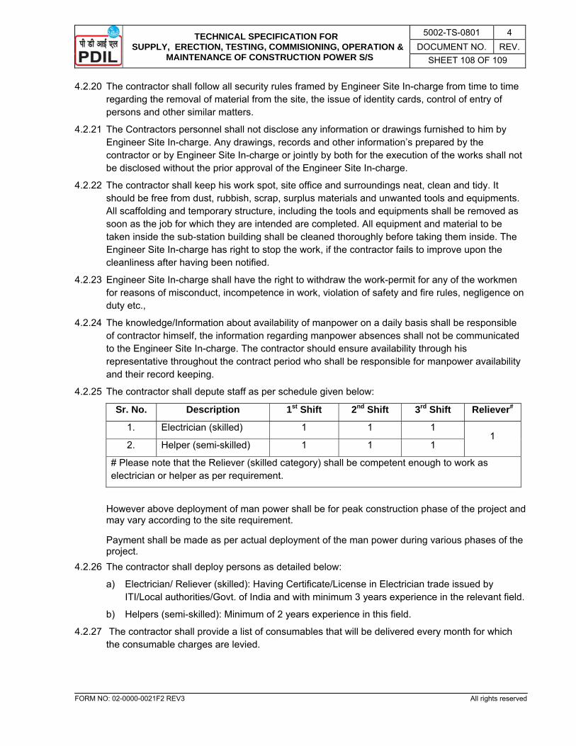
TECHNICAL SPECIFICATION FOR SUPPLY, ERECTION, TESTING, COMMISIONING, OPERATION &
MAINTENANCE OF CONSTRUCTION POWER S/S
5002-TS-0801 4 DOCUMENT NO. REV.
SHEET 108 OF 109
FORM NO: 02-0000-0021F2 REV3 All rights reserved
4.2.20 The contractor shall follow all security rules framed by Engineer Site In-charge from time to time regarding the removal of material from the site, the issue of identity cards, control of entry of persons and other similar matters.
4.2.21 The Contractors personnel shall not disclose any information or drawings furnished to him by Engineer Site In-charge. Any drawings, records and other information’s prepared by the contractor or by Engineer Site In-charge or jointly by both for the execution of the works shall not be disclosed without the prior approval of the Engineer Site In-charge.
4.2.22 The contractor shall keep his work spot, site office and surroundings neat, clean and tidy. It should be free from dust, rubbish, scrap, surplus materials and unwanted tools and equipments. All scaffolding and temporary structure, including the tools and equipments shall be removed as soon as the job for which they are intended are completed. All equipment and material to be taken inside the sub-station building shall be cleaned thoroughly before taking them inside. The Engineer Site In-charge has right to stop the work, if the contractor fails to improve upon the cleanliness after having been notified.
4.2.23 Engineer Site In-charge shall have the right to withdraw the work-permit for any of the workmen for reasons of misconduct, incompetence in work, violation of safety and fire rules, negligence on duty etc.,
4.2.24 The knowledge/Information about availability of manpower on a daily basis shall be responsible of contractor himself, the information regarding manpower absences shall not be communicated to the Engineer Site In-charge. The contractor should ensure availability through his representative throughout the contract period who shall be responsible for manpower availability and their record keeping.
4.2.25 The contractor shall depute staff as per schedule given below:
Sr. No. Description 1st Shift 2nd Shift 3rd Shift Reliever#
1. Electrician (skilled) 1 1 1 1
2. Helper (semi-skilled) 1 1 1
# Please note that the Reliever (skilled category) shall be competent enough to work as electrician or helper as per requirement.
However above deployment of man power shall be for peak construction phase of the project and may vary according to the site requirement.
Payment shall be made as per actual deployment of the man power during various phases of the project.
4.2.26 The contractor shall deploy persons as detailed below:
a) Electrician/ Reliever (skilled): Having Certificate/License in Electrician trade issued by ITI/Local authorities/Govt. of India and with minimum 3 years experience in the relevant field.
b) Helpers (semi-skilled): Minimum of 2 years experience in this field.
4.2.27 The contractor shall provide a list of consumables that will be delivered every month for which the consumable charges are levied.

TECHNICAL SPECIFICATION FOR SUPPLY, ERECTION, TESTING, COMMISIONING, OPERATION &
MAINTENANCE OF CONSTRUCTION POWER S/S
5002-TS-0801 4 DOCUMENT NO. REV.
SHEET 109 OF 109
FORM NO: 02-0000-0021F2 REV3 All rights reserved
4.3 TECHNICAL AND GENERAL SPECIFICATIONS
4.3.1 TOOLS & TACKLES:
All tools and tackles required for the safe and satisfactory operation and maintenance including preventive and break down maintenance of the substation and related equipment shall be provided by the contractor. The careful maintenance and management of these tools will be the responsibility of the contractor. The tools and tackles, apart from other things, must comprise of : a) Discharge rods suitable for 33, 3.3kV (minimum Three No’s)
b) Tubular & Box Spanners - 2 sets each.
c) Complete set of all sizes of screw drivers - 2 sets
d) Complete Tool Box - 2 nos.
e) 2 Nos. Blower & Vacuum Cleaner.
f) Minimum three sets of hand gloves of each HT & LT of different voltage ratings, 5 Nos. Helmets, 5 nos. safety belts.
g) 2 Nos. of heavy duty dry cell or rechargeable (without acid) torches.
h) Rain coats and gum boots as required.
i) First aid box.
j) 1 No. Insulation tester 5 kV capacity.
k) 1 No. Insulation tester 1 kV capacity.
l) 2 nos. Multi meter Analog & Digital.
m) 2 nos. Tong tester.
n) Cable crimping tools of adequate capacity etc.
o) Extension Power supply boards (single phase).
p) Phase Sequence meters.
4.3.2 This Maintenance scope (includes both preventive and breakdown maintenance) is indicative only and shall include other maintenance activities required for satisfactory operation.
4.3.3 Breakdown maintenance shall be provided as and when the situation warrants with a failure/fault in the system. The breakdown maintenance shall be attended at the highest priority so as to make good the faulted system and putting into operation. For breakdown maintenance, the contractor shall coordinate/liaison with Engineering Officer cum Officer In-charge and the original equipment manufacturer for replacement of parts and services as necessary.
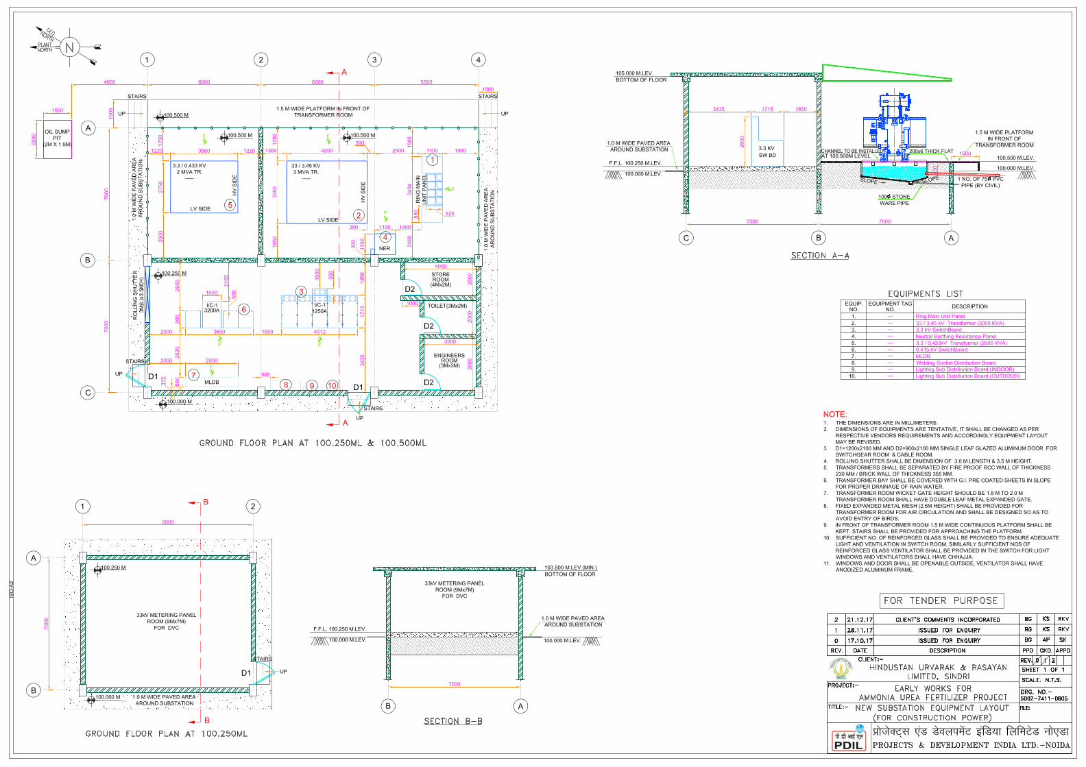
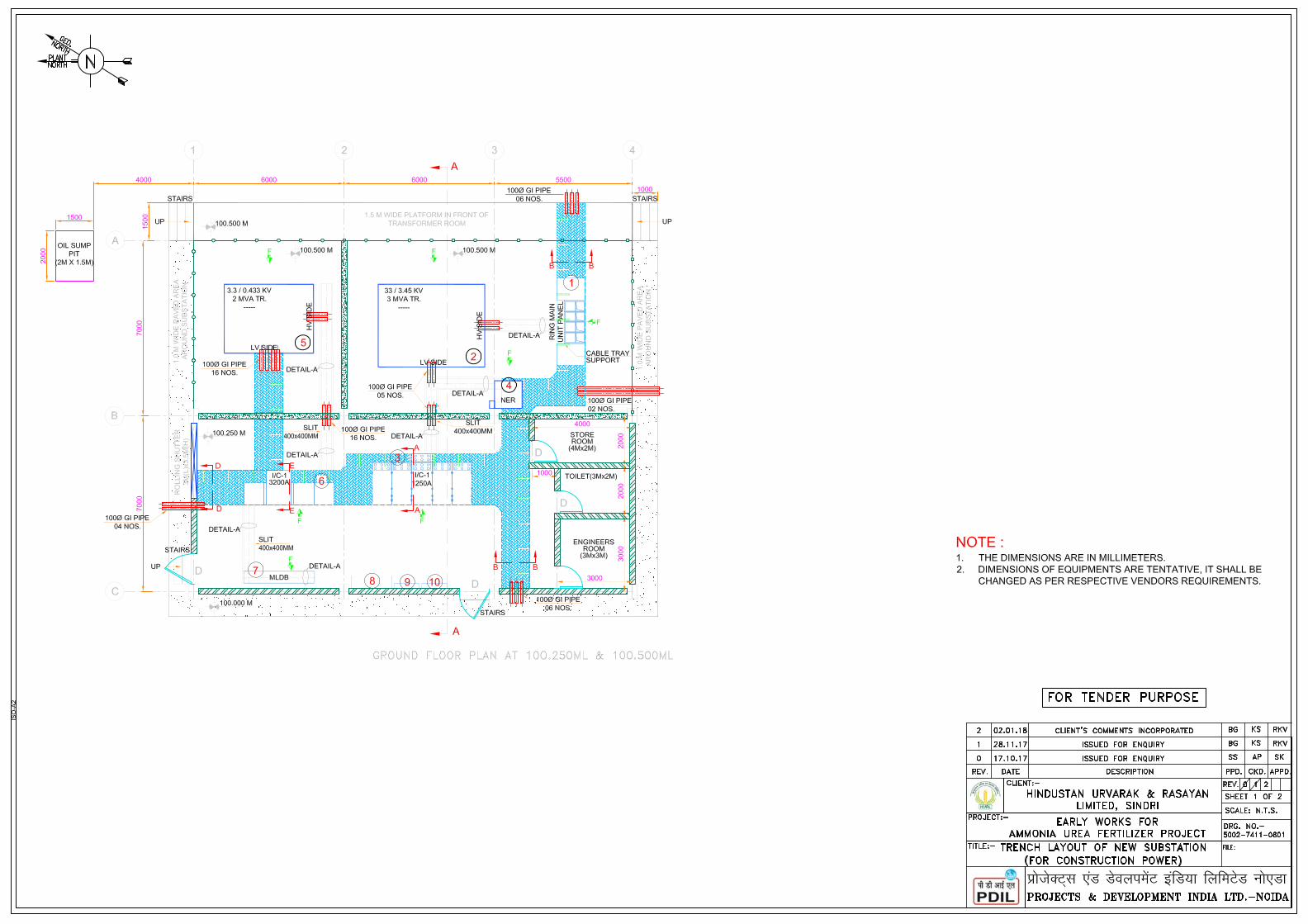
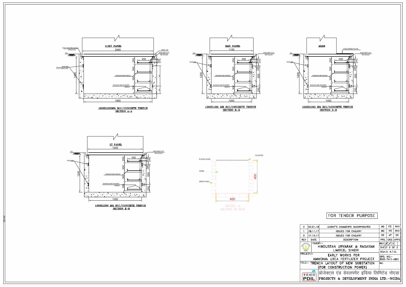

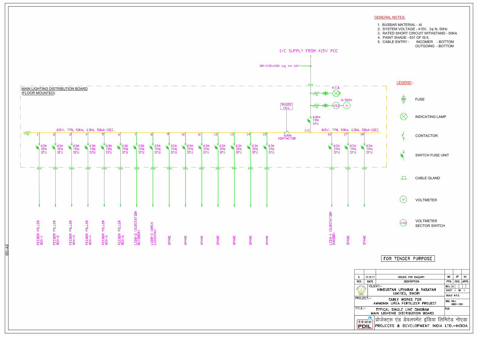
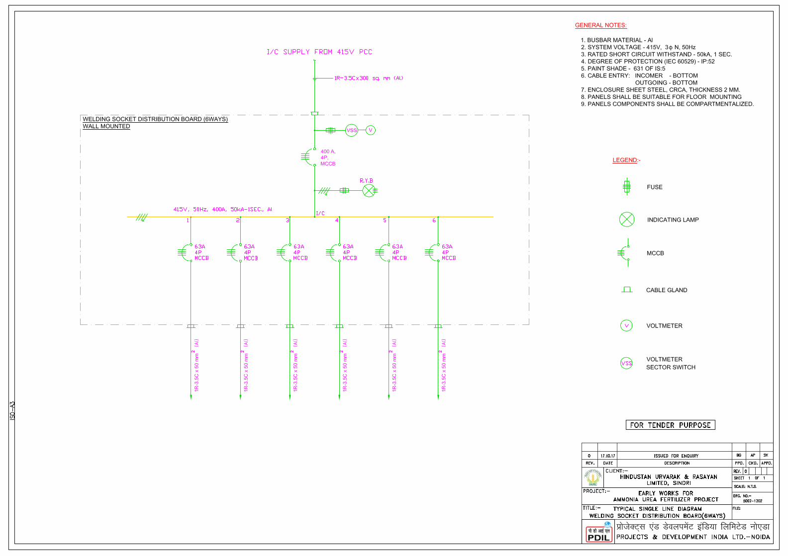


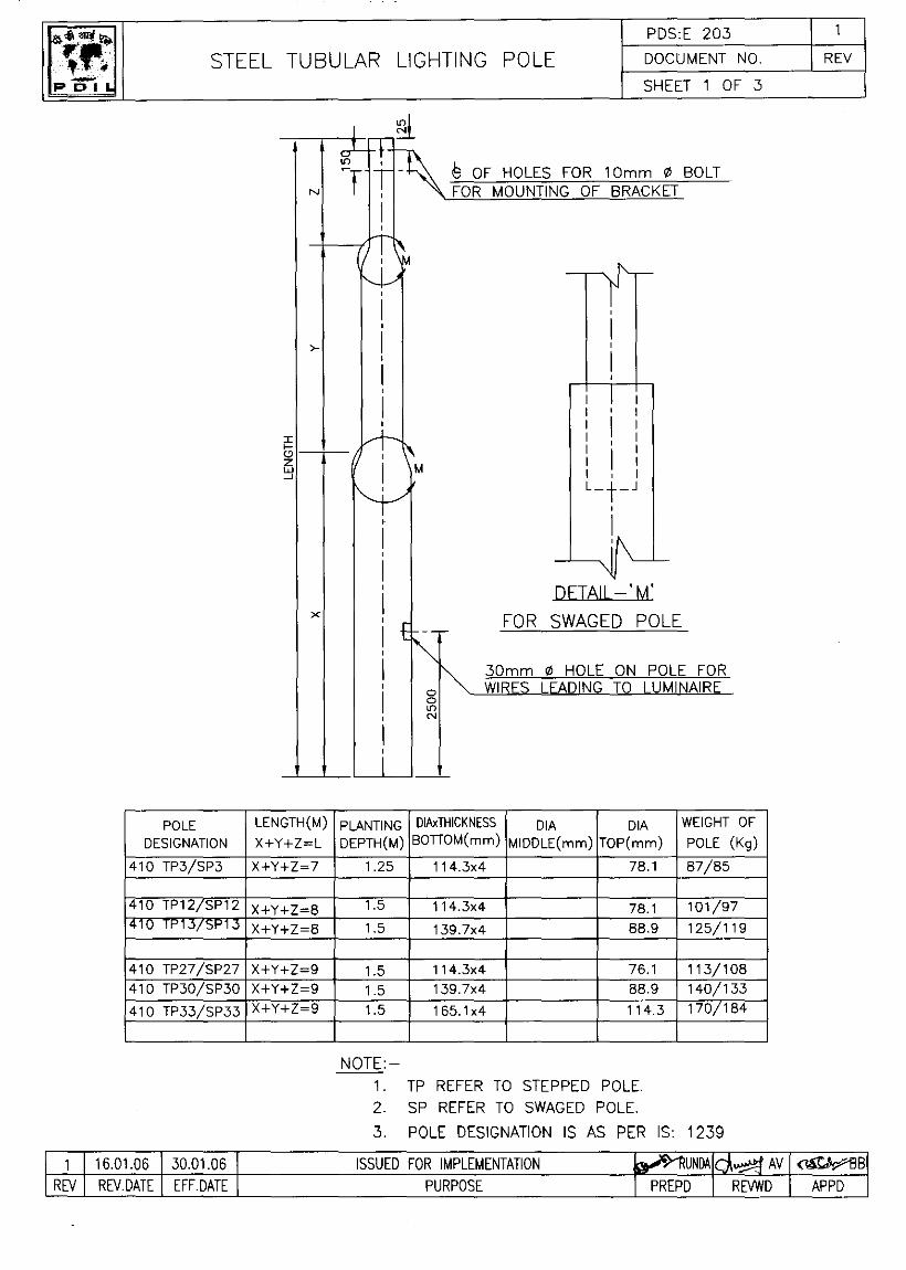
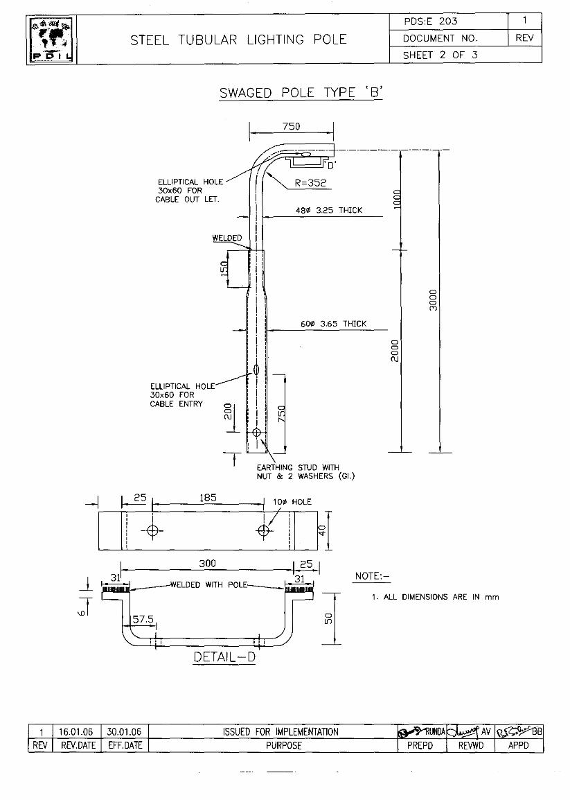
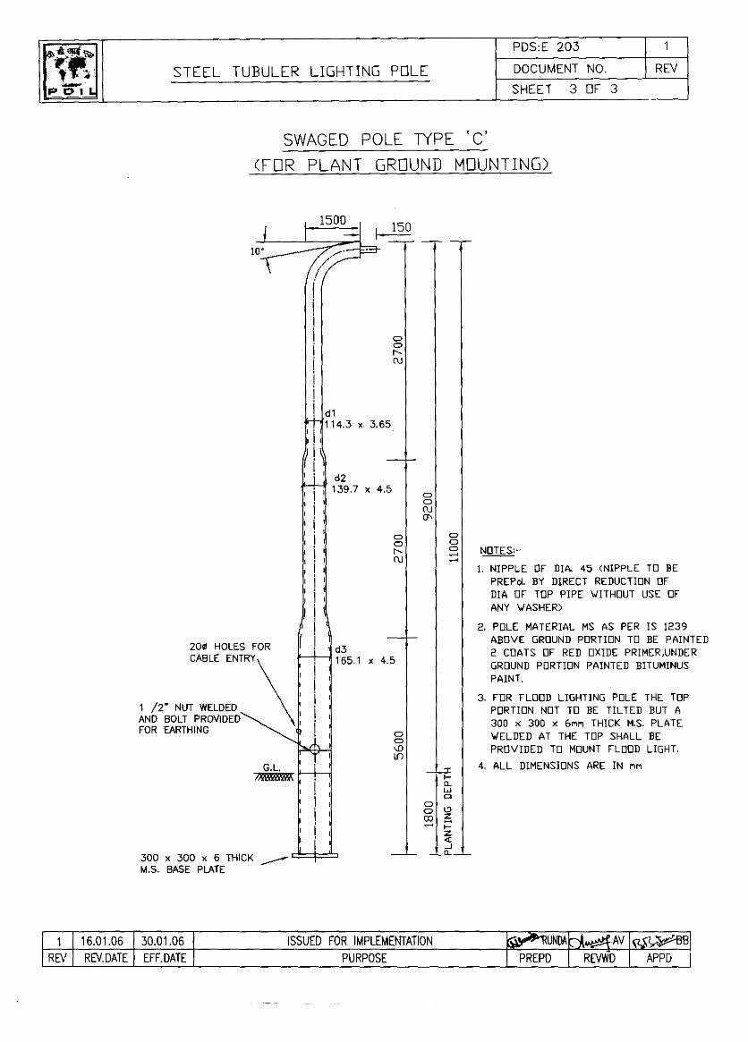


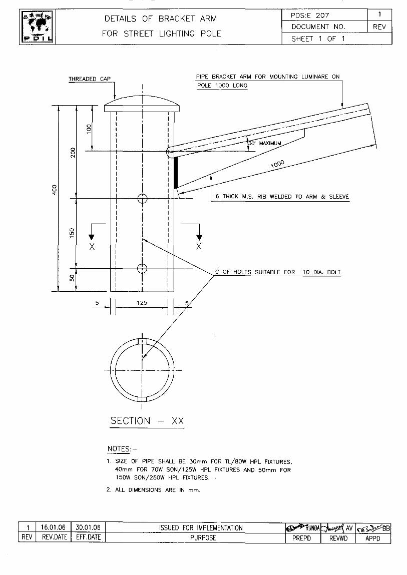

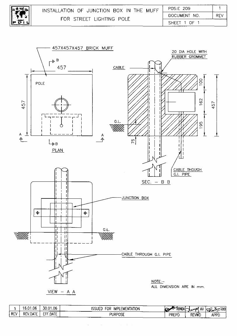

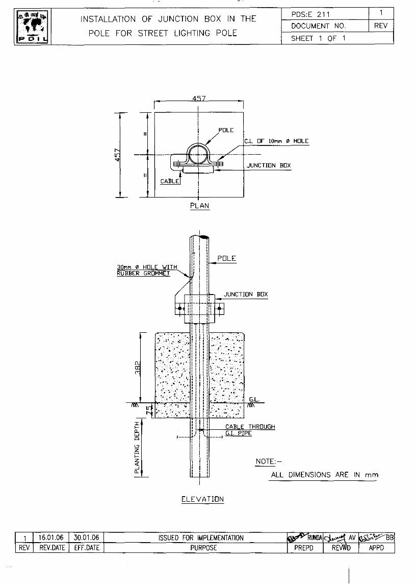
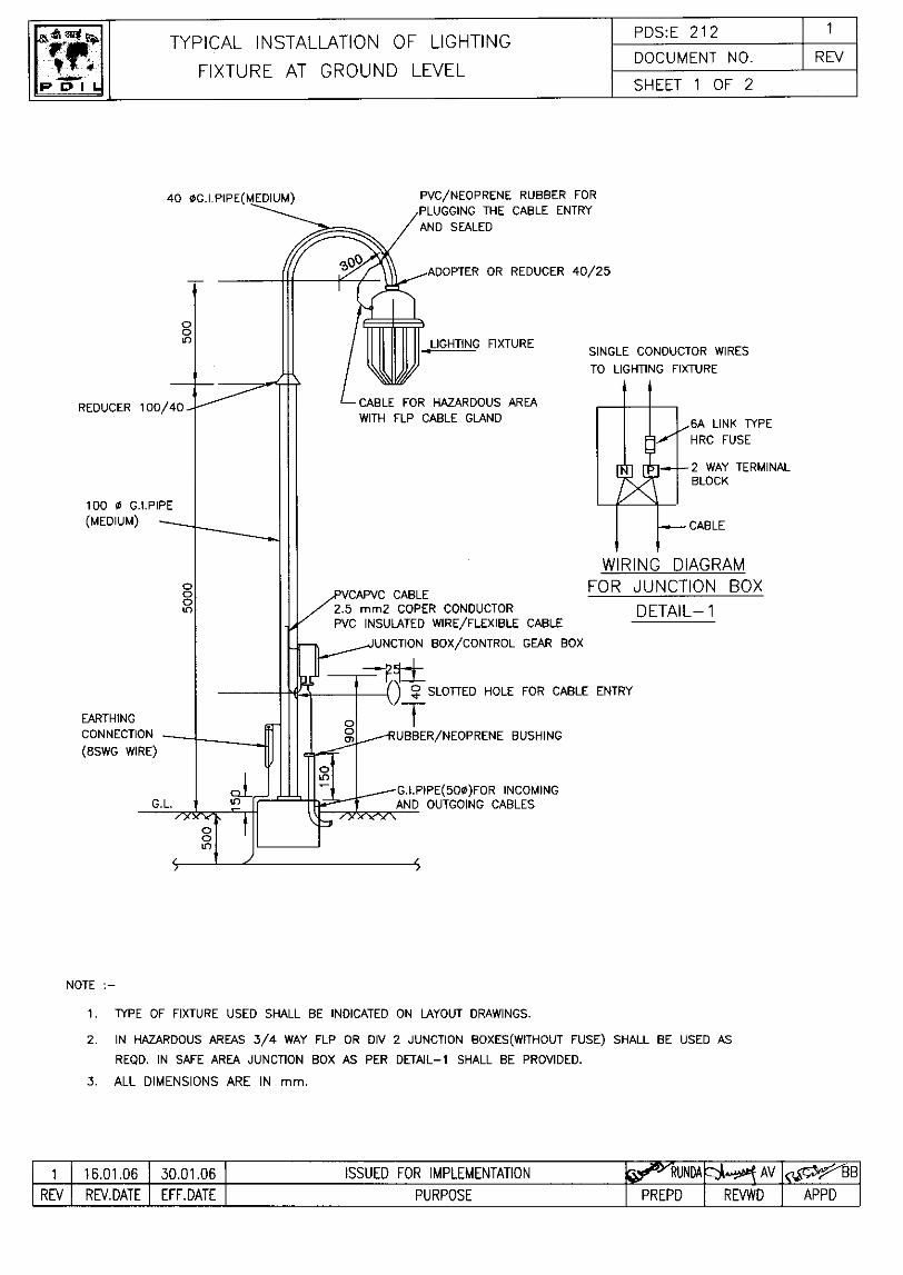
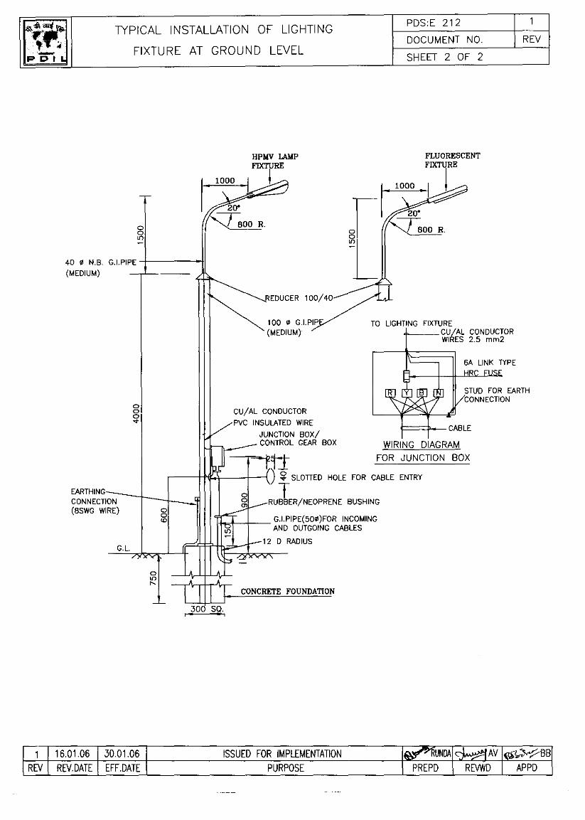
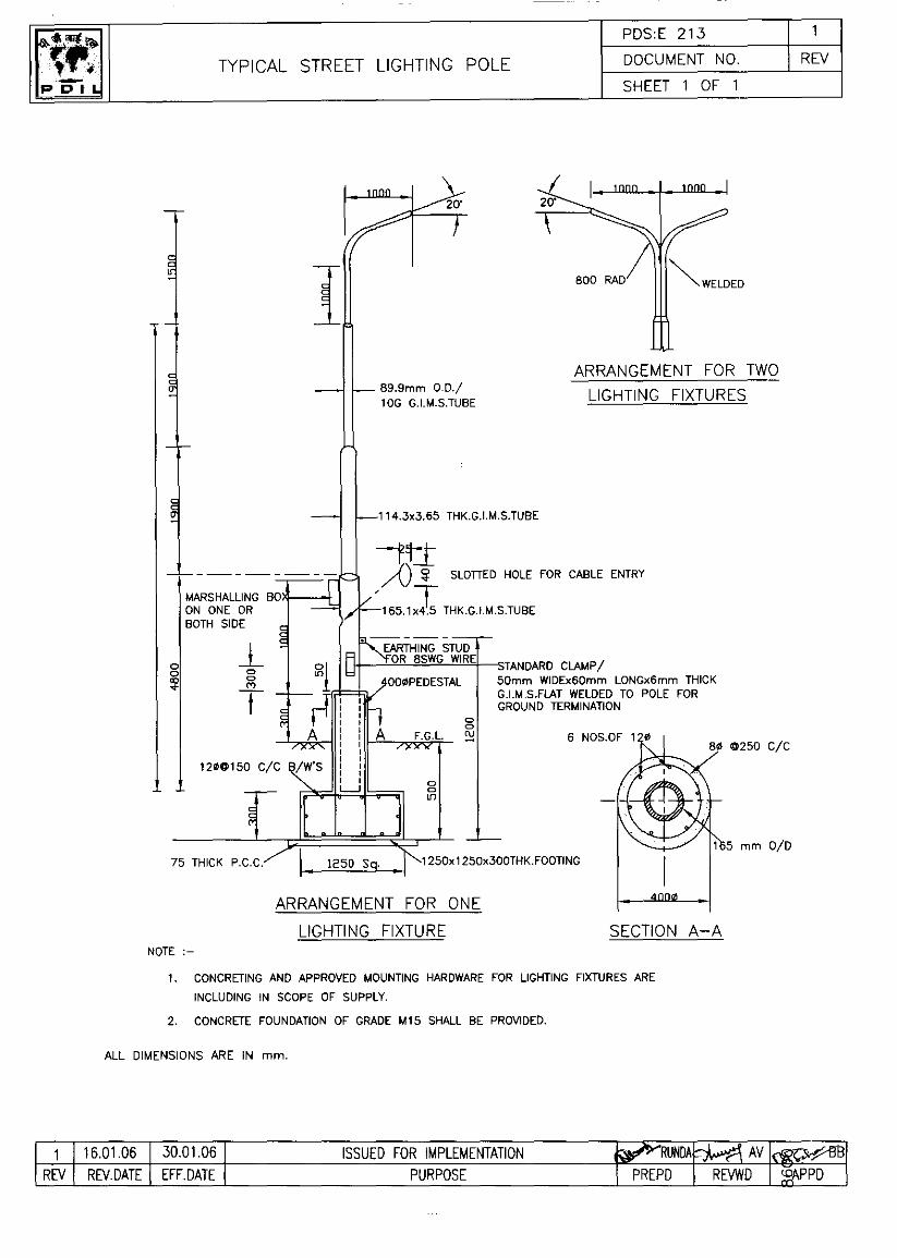

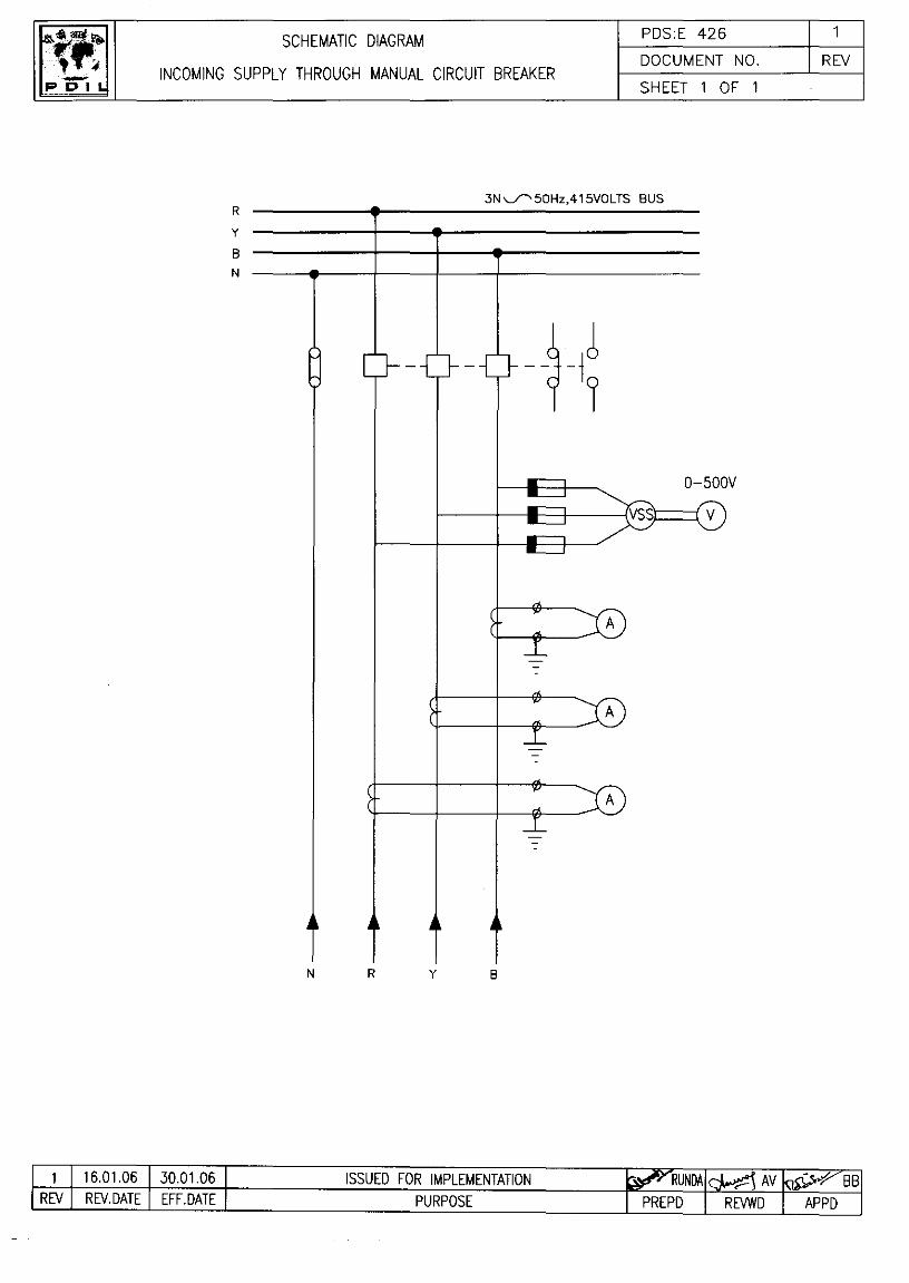

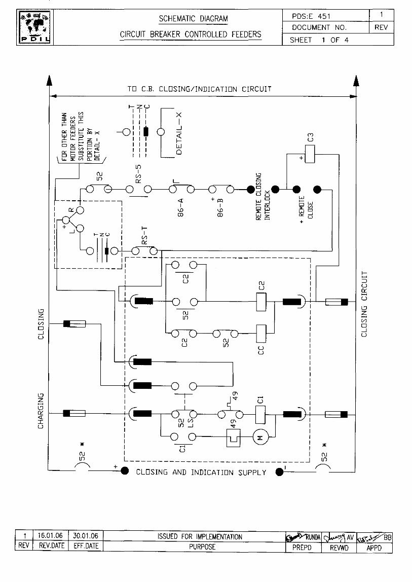
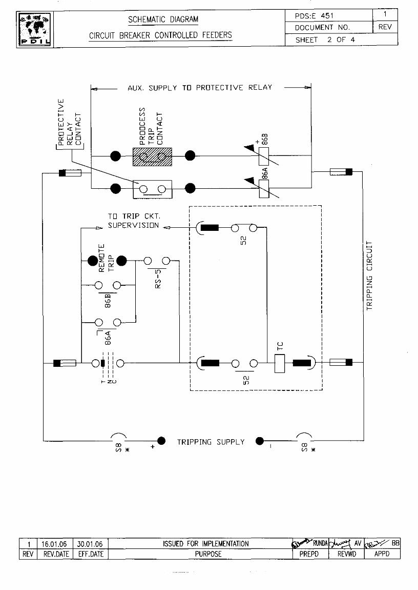
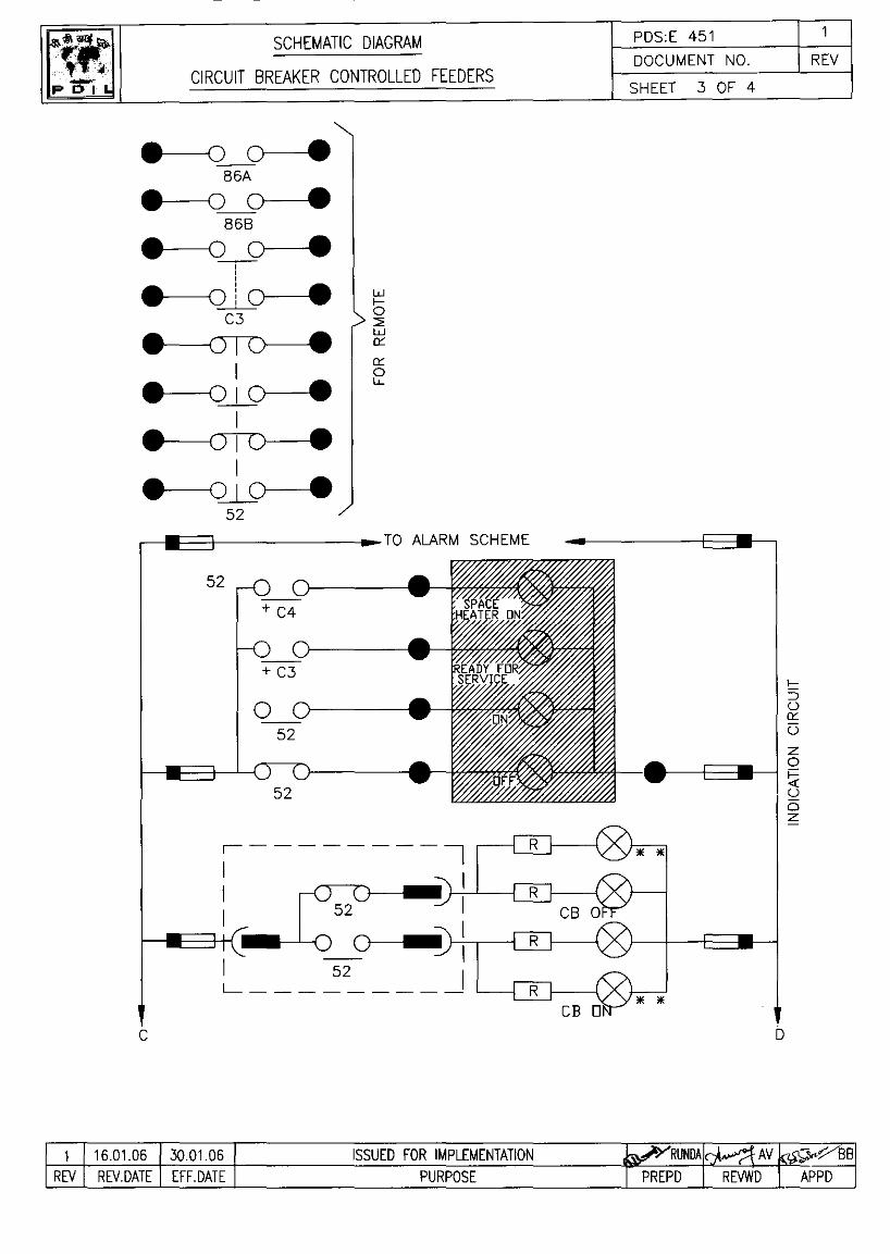

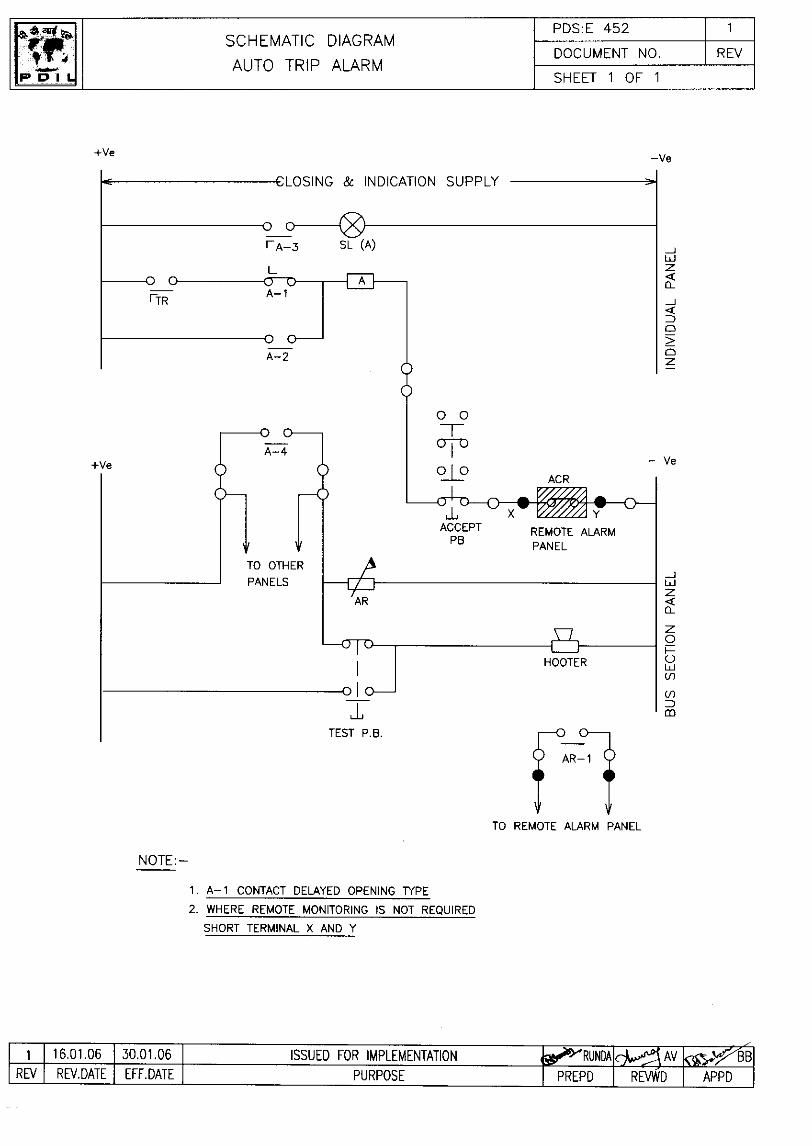
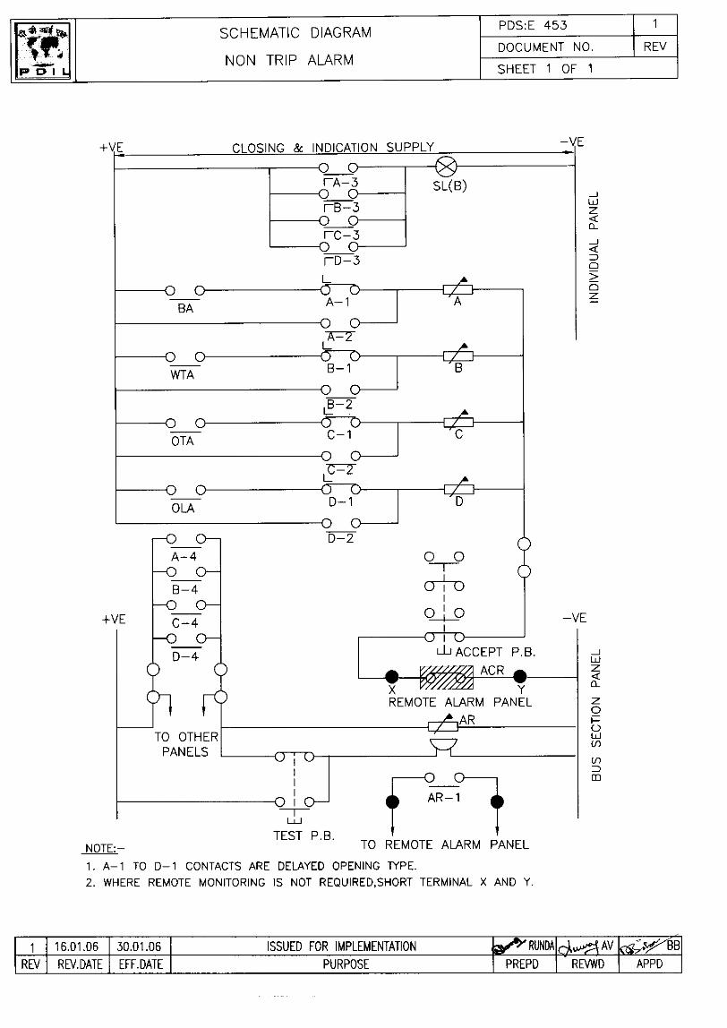
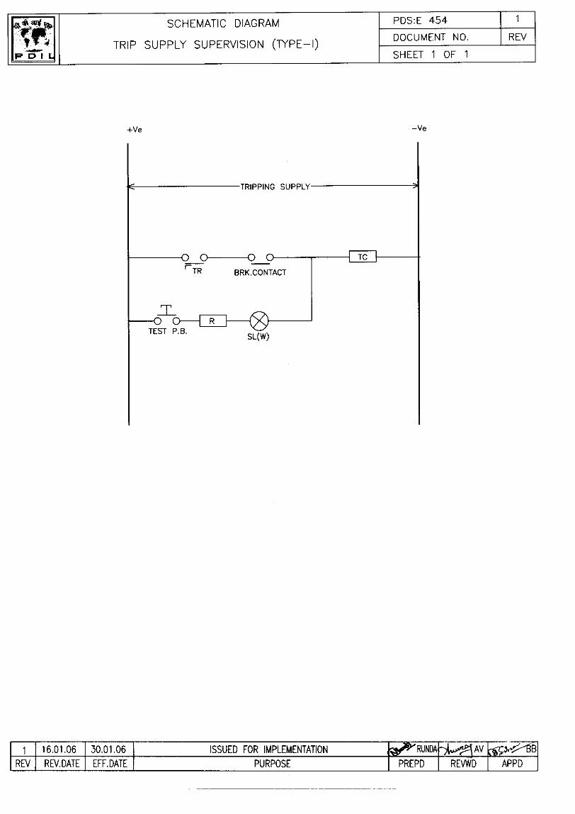
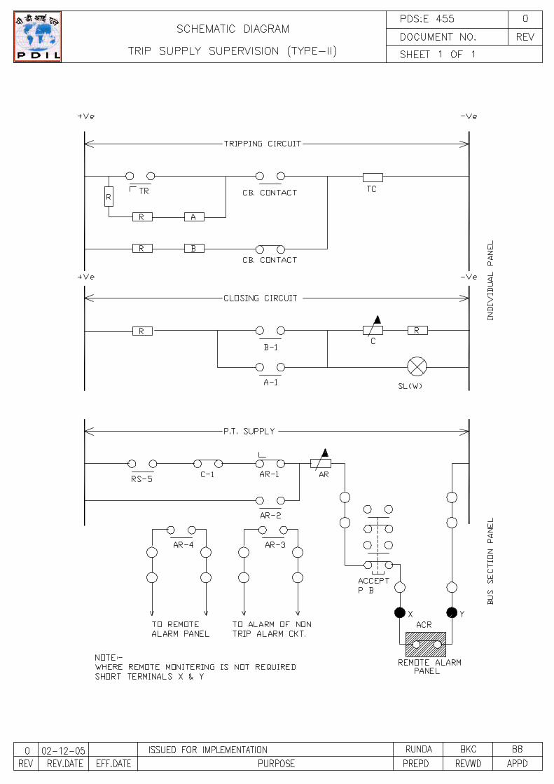
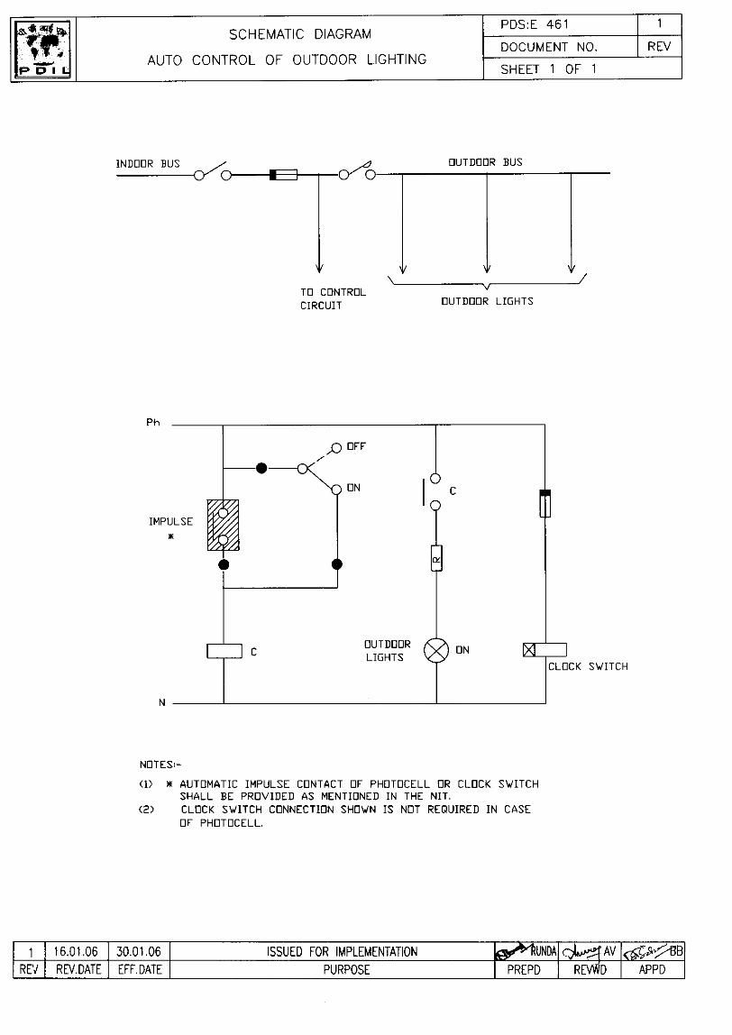

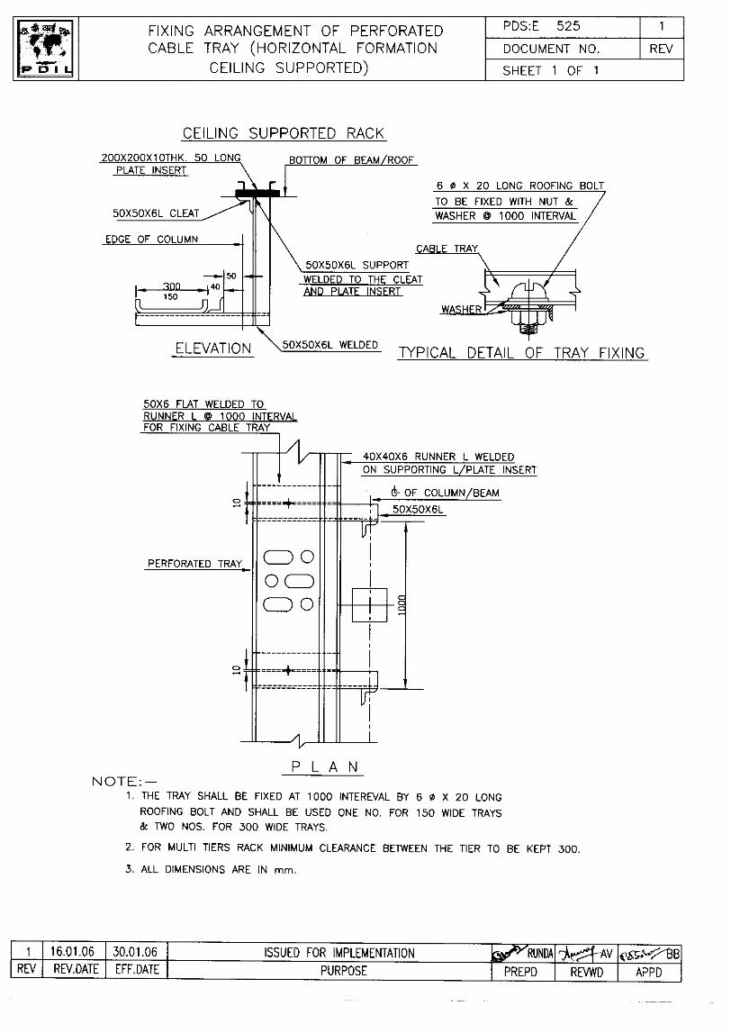
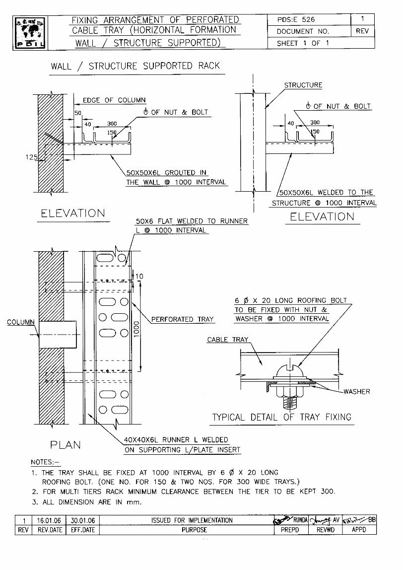
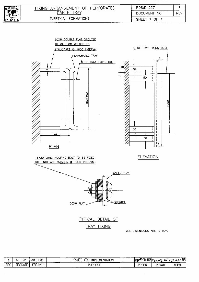
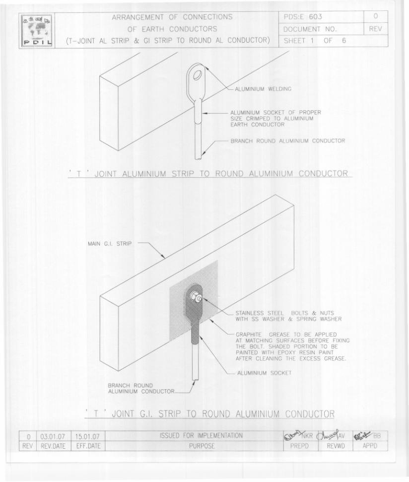
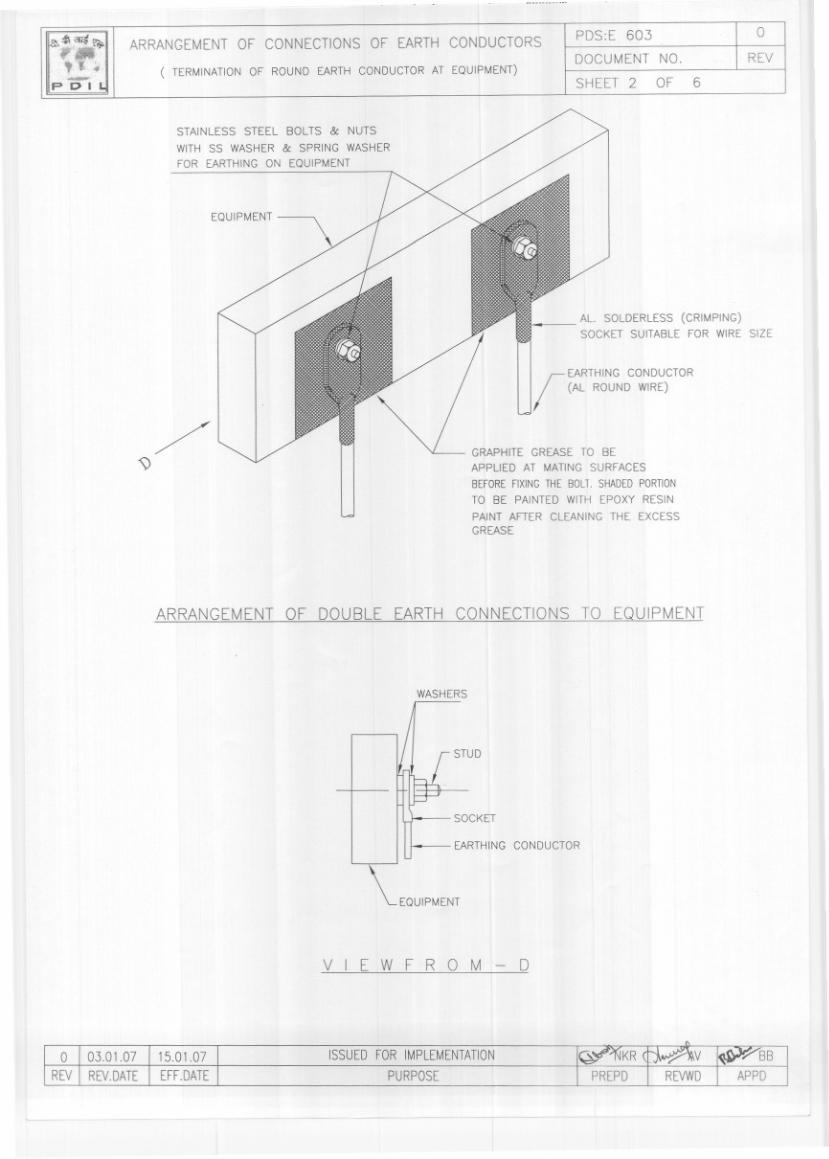


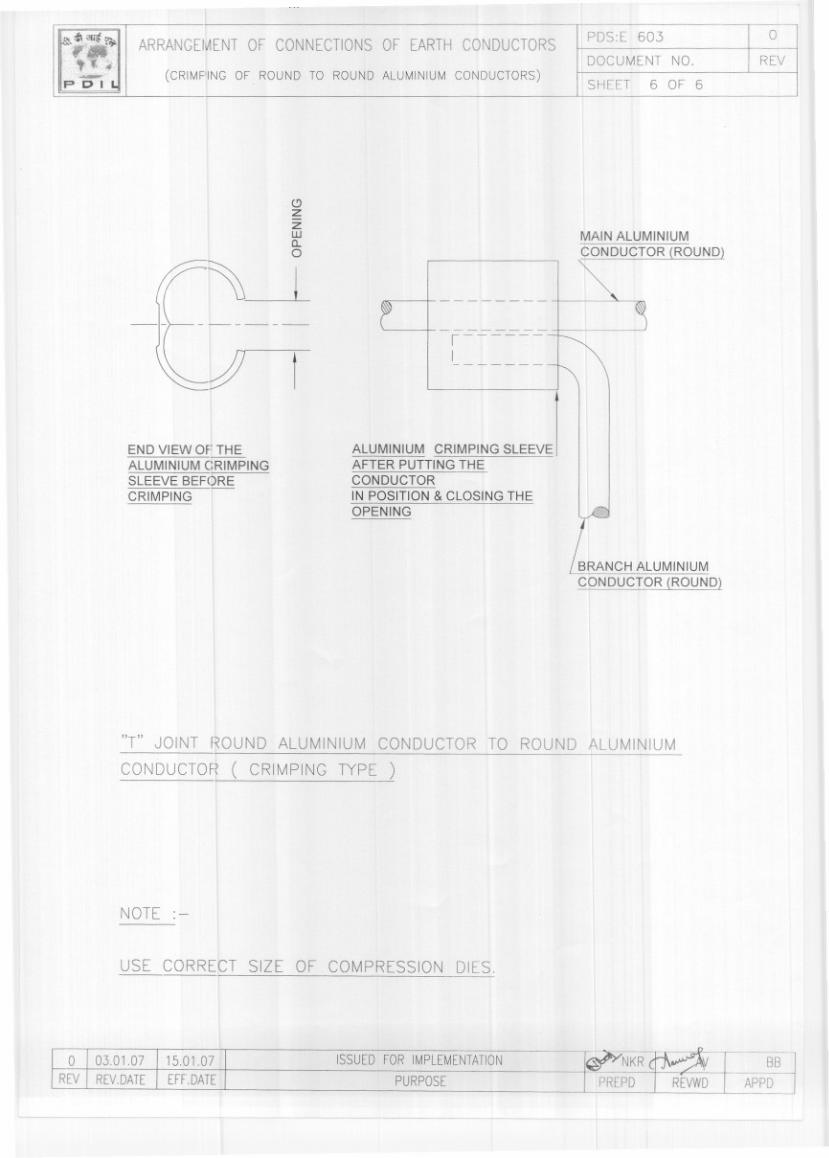
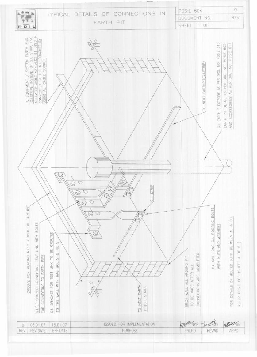
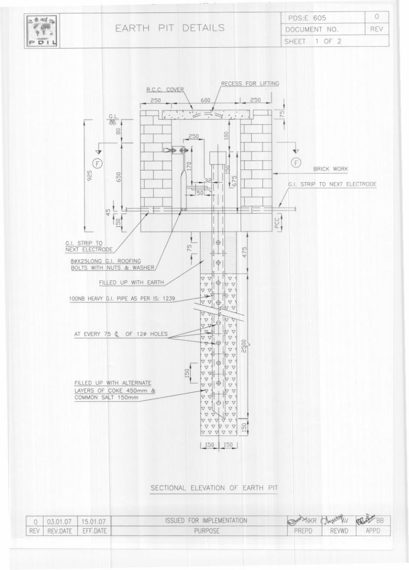
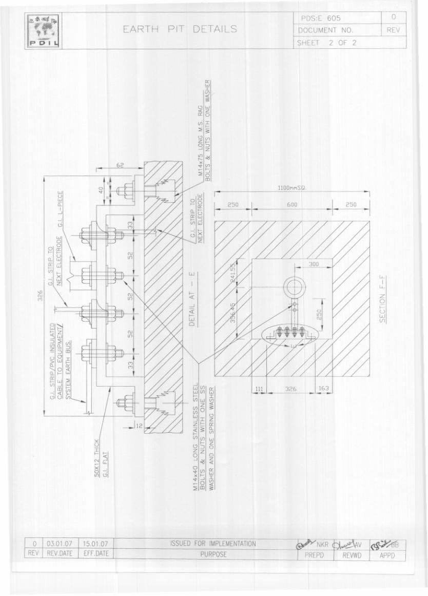
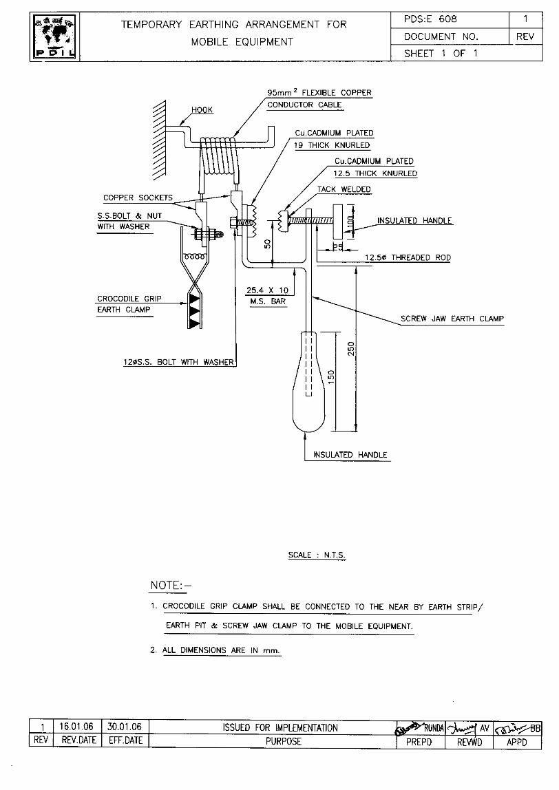

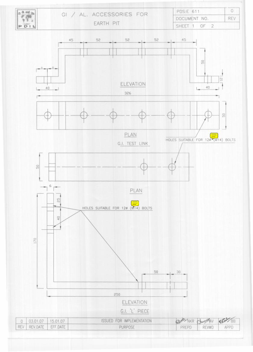
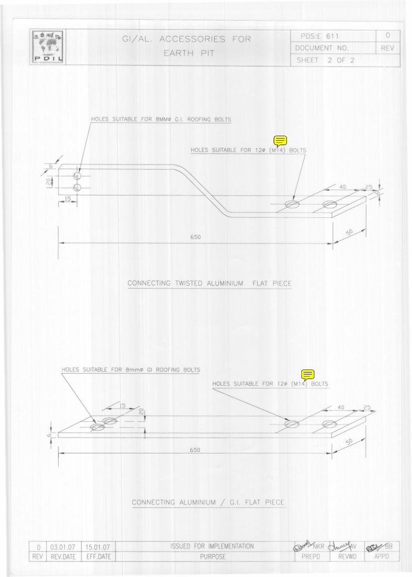
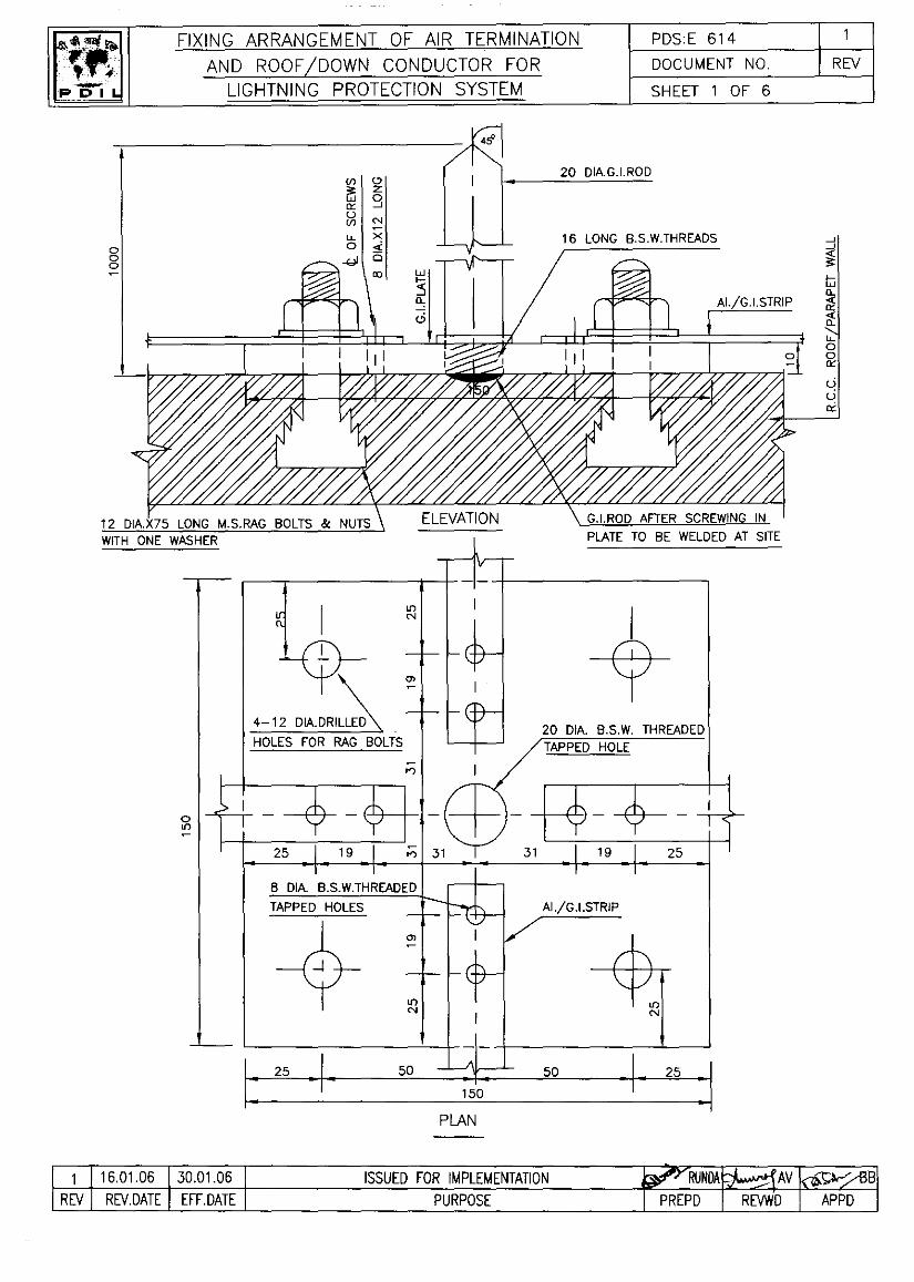

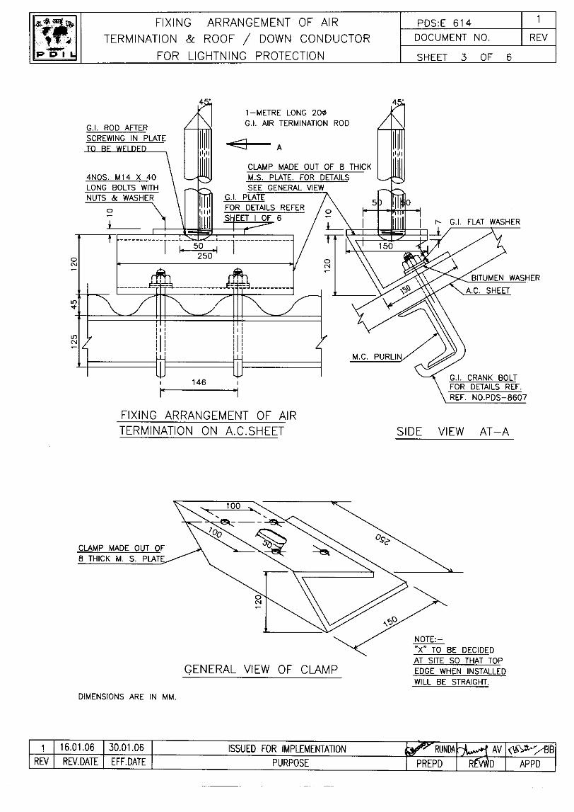

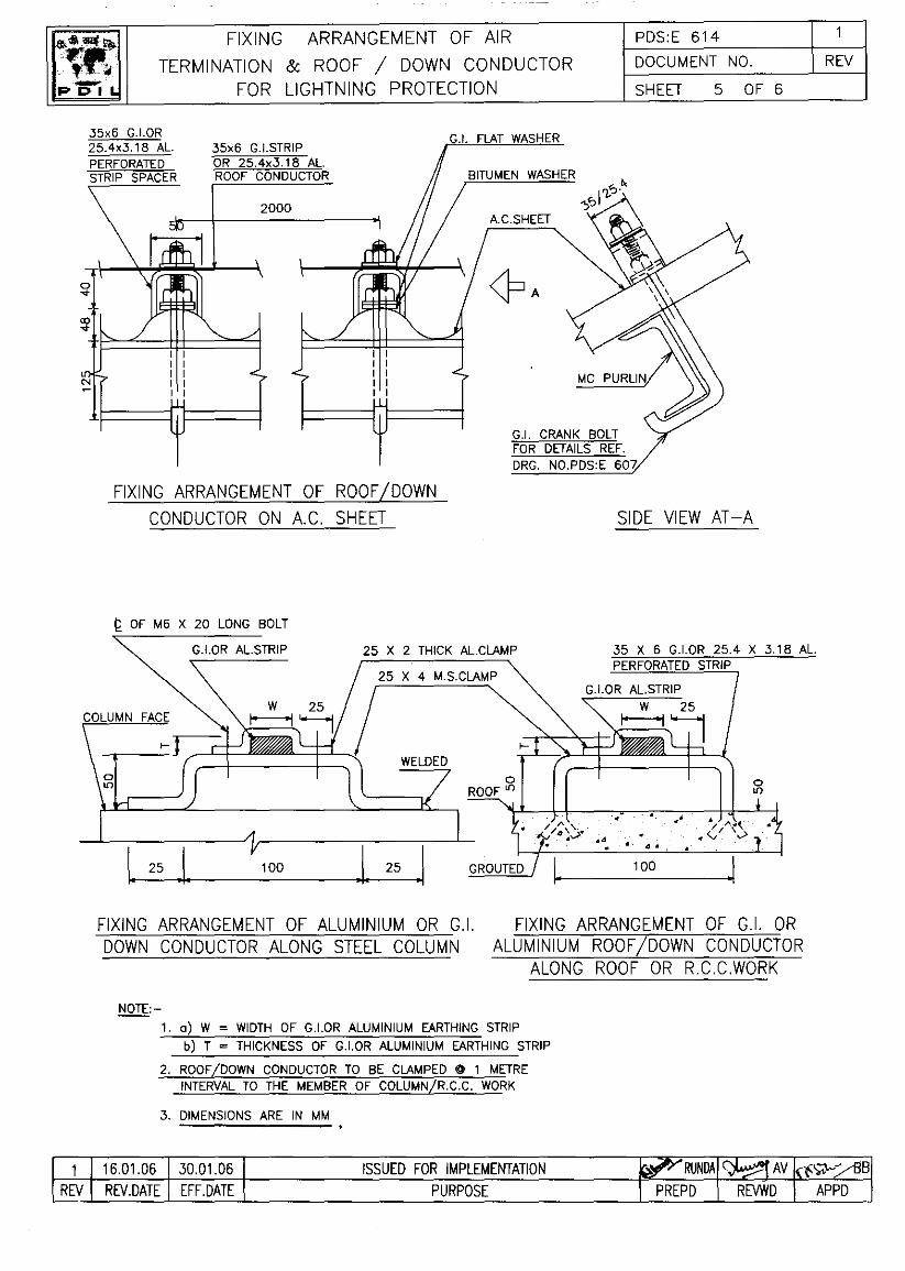


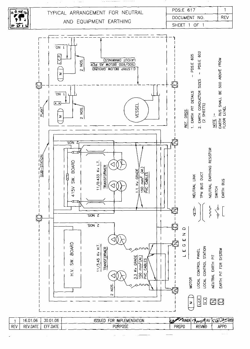
ES 2516 1
PROJECTS & DEVELOPMENT INDIA LTD DOCUMENT NO REV SHEET 1 OF 34
1 28.02.2009 30.01.2009 REVISED & ISSUED FOR IMPLEMENTATION RVV MKS0 15.01.99 FOR EMPLEMENTATION
REV REV DATE EFF DATE PURPOSE PREPD REVWD APPD FORM NO: 02-0000-0021F1 REV2 All rights reserved
TECHNICAL SPECIFICATIONS FOR
CIVIL, STRUCTURAL AND
OTHER ALLIED WORKS

TECHNICAL SPECIFICATIONS ES 2516 1
FOR CIVIL, STRUCTURAL DOCUMENT NO REV
AND OTHER ALLIED WORKS SHEET 2 OF 34
FORM NO: 02-0000-0021F2 REV1 All rights reserved
CONTENTS
Sl. No. Description Sheet Number
1. GENERAL 3
2. REFERENCE CODES AND STANDARDS 3
3. EARTH WORK 5
4. PLAIN AND REINFORCED CONCRETE WORK 9
5. STEEL REINFORCEMENT 15
6. FORM WORK 16
7. BRICK WORK 17
8. WOOD WORK 19
9. STRUCTURAL STEEL WORK 19
10. PAINTING ON STRUCTURAL STEEL 24
11. M.S. GALVANISED GRATING 29
12. ALUMINIUM GRATING 29
13. STEEL/ALUMINIUM DOORS,WINDOWS AND VENTILATORS 30
14. NON-ASBESTOS SHEETS FOR ROOFING AND CLADDING.
30
15. FLOORING AND PAVING 30
16. PLASTERING 31
17. WHITE & COLOUR WASHING, CEMENT PAINTING 32
18. GLAZING 33
TECHNICAL SPECIFICATIONS ES 2516 1
FOR CIVIL, STRUCTURAL DOCUMENT NO REV
AND OTHER ALLIED WORKS SHEET 3 OF 34
FORM NO: 02-0000-0021F2 REV1 All rights reserved
1.0 GENERAL
1.1 Specifications of materials and workmanship shall be as described in the Central Public Works Department Specifications Vol. I to VI (latest) including latest amendments, unless otherwise specified. These CPWD Specifications shall be deemed to form part of this contract. The CONTRACTOR shall procure and maintain copies of the latest CPWD Specifications at site for reference.
1.2 These technical Specifications shall be supplementary to the specifications contained in the CPWD specifications, wherever at variance, these Particular Specifications shall take precedence over the provisions in the CPWD Specifications.
1.3 Site clearing - Site clearing means the cutting of trees, bushes, shrubs etc. and the pulling out of roots and stumps to effect a general cleaning of the site area. All these materials shall be removed from the site area at the CONTRACTOR's expenses and responsibility and shall be disposed off as directed by Engineer-in-Charge. Trees, bushes, roots, stumps and other materials shall not be disposed off by burning within the site boundaries unless the Engineer-in-Charge permits.
2.0 REFERENCE CODES & STANDARDS
2.1 Wherever reference of BIS Specifications/ or BIS Codes of Practice are made in the Specifications/ Schedule of Rates or Preambles, reference shall be to the latest edition of BIS (Bureau of Indian Standards).
BIS - 109 Ready mixed paint, brushing, priming, plaster to Indian Standard colour No. 631 & 361 white and off-white.
BIS - 248 Sodium bisulphite, technical (sodium metabisuphite).
BIS - 383 Coarse & Fine aggregates from natural sources for concrete.
BIS - 419 Putty, for use on window frames.
BIS - 427 Distemper, dry, colour as required.
BIS - 432 Mild Steel & Medium tensile steel bars.
BIS - 456 Code of Practice for Plain and Reinforced Concrete.
BIS - 515 Natural and Manufactured aggregates for use in mass concrete
BIS - 730 Hook bolts for corrugated sheet roofing
BIS - 800 Code of Practice for General Construction in Steel
BIS - 814 Covered electrodes for manual metal arc welding of carbon and carbon manganese steel.
BIS - 815 Classification coding of covered electrodes for metal arc welding of structural steels.
BIS - 816 Metal Arc Welding for General Construction of Mild Steel.
TECHNICAL SPECIFICATIONS ES 2516 1
FOR CIVIL, STRUCTURAL DOCUMENT NO REV
AND OTHER ALLIED WORKS SHEET 4 OF 34
FORM NO: 02-0000-0021F2 REV1 All rights reserved
BIS - 817 Code of practice for training and testing of metal arc welders.
BIS - 883 Code of practice for structural timber in building.
BIS - 1038 Steel doors, windows and ventilators
BIS - 1079 Hot rolled carbon steel sheets & strips
BIS - 1081 Code of practice for fixing and glazing of metal (steel & aluminium) doors, windows and ventilators.
BIS - 1161 Steel tubes for structural purposes.
BIS - 1285 Wrought aluminium & aluminium alloy extruded round tube and hollow sections
BIS - 1361 Steel windows for Industrial Buildings.
BIS - 1363 Hexagon head bolts, screws & nuts of product grade C : Part - I Hexagon head bolts ( size range M5 to M64)
BIS - 1367 Technical supply conditions for threaded steel fasteners
BIS - 1566 Hard - Drawn steel wire fabric for concrete reinforcement.
BIS - 1786 High strength deformed steel bars & wires for concrete reinforcement.
BIS - 2062 Steel for general structural purposes.
BIS - 2116 Sand for masonry mortars.
BIS - 2212 Code of practice for brickwork.
BIS - 2386 Methods of test for aggregates.
BIS - 2553 Safety glass: Part-I General purpose.
BIS - 2835 Flat transparent sheet glass
BIS - 3007 Code of practice for laying of asbestos cement sheets.
BIS - 4021 Timber door, window and ventilator frames
BIS - 4923 Hollow Steel sections for structural use.
BIS - 4925 Concrete batching and mixing plant.
BIS - 5410 Cement Paint
BIS - 6477 Dimensions for wrought aluminium & aluminium alloys, extruded hollow sections.
BIS - 7318 Fusion welding of steel.
BIS - 10262 Recommended guidelines for concrete mix design.
IS - 14871 Products in Fibre Reinforced Cement – Long Corrugated or Asymmetrical Section Sheets and Fittings for Roofing and Cladding - Specification

TECHNICAL SPECIFICATIONS ES 2516 1
FOR CIVIL, STRUCTURAL DOCUMENT NO REV
AND OTHER ALLIED WORKS SHEET 5 OF 34
FORM NO: 02-0000-0021F2 REV1 All rights reserved
3.0 EARTHWORK
3.1 EXCAVATION
3.1.1 Excavation shall be carried out in soil of any nature and consistency, in the presence of water or in the dry, met on the site to the lines, levels and contours shown on the detailed drawings and CONTRACTOR shall remove all excavated materials to soil heaps on site or transport for use in filling on the site or stack them for reuse as directed by the Engineer-in-Charge.
3.1.2 Surface dressing shall be carried out on the entire area occupied by the buildings including plinth protection as directed without any extra cost. The depths of excavation shown on the drawings are the depths after surface dressing.
3.1.3 The site around all buildings and structures to a width of 3 metres beyond the edge of plinth protection, ramps, steps, etc. shall be dressed and sloped away from the buildings.
3.1.4 Black cotton soil, and other expansive or unsuitable soils excavated shall not be used for filling in foundations, and plinths of buildings or in other structures including manholes, septic tanks etc. and shall be disposed off within the contract area marked on the drawings, as directed, leveled and neatly dressed.
3.1.5 In case of trenches exceeding 2 metres depth or where soil is soft or slushy, the sides of trenches shall be protected by timbering and shoring. The CONTRACTOR shall be responsible to take all necessary steps to prevent the sides of trenches from caving in or collapsing. The extent and type of timbering and shoring shall be as directed by the Engineer-in-Charge.
3.1.6 Where the excavation is to be carried out below the foundation level of adjacent structure, the precautions to be taken such as under pinning, shoring and strutting etc. shall be determined by Engineer-in-Charge. No excavation shall be done unless such precautionary measures are carried out as per directions of Engineer-in-Charge.
3.1.7 Specification for Earth work shall also apply to excavation in rock in general. The excavation in rock shall be done such that extra excavation beyond the required width and depth as shown in drawings is not made. If the excavation done in depth greater than required /ordered. The CONTRACTOR shall fill the extra excavation with concrete of mix 1:5:10 as the foundation concrete at his own cost.
3.1.8 CONTRACTOR shall make all necessary arrangements for dewatering / defiling as required to carry out proper excavation work by bailing or pumping out water, which may accumulate in the excavation pit from any cause/ source whatsoever.
3.1.9 CONTRACTOR shall provide suitable draining arrangements at his own cost to prevent surface water entering the foundation pits from any source.
TECHNICAL SPECIFICATIONS ES 2516 1
FOR CIVIL, STRUCTURAL DOCUMENT NO REV
AND OTHER ALLIED WORKS SHEET 6 OF 34
FORM NO: 02-0000-0021F2 REV1 All rights reserved
3.1.10 The CONTRACTOR is forbidden to commence the construction of structures or to carry out concreting before Engineer-in-Charge has inspected, accepted and permitted the excavation bottom.
3.1.11 Excavation in disintegrated rock means rock or Boulders including brickbats which may be quarried or split with crow bars. This will also include laterite and hard conglomerate.
3.1.12 Excavations in hard rock - meant excavation made in hard rock to be done manually, or by blasting using only explosives and / or pneumatic hammers. In case of blasting, control blasting should be adopted depending on site conditions. For using explosives CONTRACTOR shall follow all provisions of Indian Explosives Act / Rules 1983, corrected / revised up to date.
3.1.13 In case of hard rock excavation to be carried out using explosives the, CONTRACTOR shall obtain the written approval in advance.
3.1.14 The measurements for excavations shall be restricted and limited to minimum excavation line as per drawing for payment purposes.
3.1.15 Adequate protective measures shall be taken to see that the excavation does not affect or damage adjoining structures. The CONTRACTOR shall take all measures required for ensuring stability of the excavation and safety of property and people in the vicinity. The CONTRACTOR shall erect and maintain during progress of work, temporary fences around dangerous excavations at no extra cost.
3.1.16 Excavation in ordinary soil means excavation in ordinary hard soil including stiff heavy clay, hard shale, or compact murum, or any material, which can be removed by the ordinary application of spades, shovels, picks and pick axes. This shall also include removal of isolated boulders each having a volume not more than 0.50m³.
3.1.17 Excavation in soft rock includes limestone, sandstone, laterite, hard conglomerates, etc. or other rock which can be quarried or split with crowbars or wedges. This shall also include excavation of tarred pavements, masonry work and rock boulders each having a volume of not more than 0.25m³.
3.1.18 Excavation in hard rock includes any rock bound in ledges or masses in its original form or cement concrete for which in the opinion of the Engineer-in-Charge, requires the use of compressed air, equipment, sledge hammer and blasting or non-explosive materials viz. Acconex manufactured by A.C.C. Ltd. Specifications and instructions for use shall be as per manufacturer.
3.1.19 In case of any difficulty concerning the interpretation of type of soil as mentioned above, the Engineer-in-Charge shall decide whether the excavation in a particular material is in ordinary soil, soft rock or hard rock and his decision in this matter shall be final and binding on the CONTRACTOR and without appeal.
3.2 FILLING
3.2.1 Back filling of excavations in trenches, foundations and elsewhere shall consist of one of the following materials approved by Engineer-in-Charge.

TECHNICAL SPECIFICATIONS ES 2516 1
FOR CIVIL, STRUCTURAL DOCUMENT NO REV
AND OTHER ALLIED WORKS SHEET 7 OF 34
FORM NO: 02-0000-0021F2 REV1 All rights reserved
i. Soil
ii. Sand
iii. Moorum
iv. Hard-core
v. Stone/gravel
All back filling material shall be approved by the Engineer-in-Charge.
3.2.2 Soil filling - Soil material shall be free from rubbish, roots, hard lumps and any other foreign organic material. Filling shall be done in regular horizontal layers each not exceeding 20 Cm. depth.
3.2.3 Back filling around completed foundations, structures, trenches and in plinth shall be done to the lines and levels shown on the drawings.
3.2.4 Back filling around pipes in the trench shall be done after hydro testing is done.
3.2.5 Back filling around liquid retaining structures shall be done only after leakage testing is completed and approval of Engineer-in-Charge is obtained.
3.2.6 Sand used for filling under foundation concrete, around foundation and in plinth etc. shall be fine/ coarse, strong, clean, free from dust, organic and deleterious matter. The sand filling under foundation shall be rammed with Mech. compactor. Sand material shall be approved by Engineer-in-Charge.
3.2.7 Moorum for filling, where ordered, shall be obtained from approved pits and quarries which contain siliceous material and natural mixture of clay. Moorum shall not contain any admixture of ordinary earth. Size of moorum shall vary from dust to 10 mm.
3.2.8 Hard-core shall be of broken stone of 90 mm to 10 mm size suitable for providing a dense and compact sub grade. Stones shall be sound, free from flakes, dust and other impurities. Hard core filling shall be spread and leveled in layers, 15 cm thick, watered and well compacted with ramming or with mechanical / hand compacts including hand packing wherever required.
3.2.9 If any selected fill material is required to be borrowed, CONTRACTOR shall make arrangements and procure such material from outside borrow pits. The material of source shall be subject to prior approval of Engineer-in-Charge. CONTRACTOR shall make necessary access roads to borrow areas and maintain the same, if such access roads do not exist, at no extra cost.
3.2.10 Plinth filling shall be carried out with approved material as described earlier, in layers not exceeding 150mm, watered and compacted with mechanical compaction machines. Engineer-in-Charge may however permit manual compaction by hand tampers in case he is satisfied that mechanical compaction is not possible. When filling reaches the finished level, the surface shall be flooded with water, unless otherwise directed, for at least 24 hours, allowed to dry and then the surface again compacted as specified above to avoid settlements at later stage. The finished

TECHNICAL SPECIFICATIONS ES 2516 1
FOR CIVIL, STRUCTURAL DOCUMENT NO REV
AND OTHER ALLIED WORKS SHEET 8 OF 34
FORM NO: 02-0000-0021F2 REV1 All rights reserved
level of the filling shall be trimmed to the level specified. Compacted surface shall have at least 95% of laboratory maximum dry density. A minimum of one test per 500 sq. meters of compacted area shall be done.
3.2.11 Whenever the fill material (earth or soil) is purchased, CONTRACTOR shall get the approval of Engineer-in-Charge. The CONTRACTOR shall arrange to determine the following properties of the soil and shall get the approval of Engineer-in-Charge.
Clay content : 15% to 20%
Laboratory dry density : Not less than 1600 kg/m³
Plasticity Index : Not more than 20.
3.2.12 The fill shall be compacted using a vibrating compactor of not less than 1.5 tonne. The fill shall be thoroughly compacted in layers as directed but not more than 200 mm thick. Adequate water shall be used for compaction and the density after compaction shall be not less than maximum dry density obtained in test of BIS: 2720 Part-8. Compacted surface shall have at least 95% of laboratory maximum dry density. A minimum of one test per 500 sq. meters of compacted area shall be done.
3.2.13 The Gravel fill shall be non plastic granular material, well graded, strong, with maximum particle size of 50 mm, with not more than 15% passing a 4.75 mm BIS sieve, free of all debris, vegetable matter and chemical impurities.
3.2.14 All clods, lumps etc. shall be broken before compaction.
3.2.15 In case of grading/banking successive layers of filling shall not be placed, until the layer below has been thoroughly compacted to satisfy the requirements laid down in this specification.
Prior to rolling, the moisture content of material shall be brought to within +/-2% of the optimum moisture content as described in BIS 2720 Part-7. The moisture content shall preferably be on the wet side for potentially expansive soil.
After adjusting the moisture content as described, the layers shall be thoroughly compacted by means approved by Engineer-in-Charge, till the specified maximum laboratory dry density is obtained.
General, fill shall be placed in layers not exceeding 300 mm thickness and shall be thoroughly compacted to achieve a compaction of at least 90% of laboratory maximum dry density up to a depth of 600 mm below finished grade. Final fill of 600 mm thickness shall consist of preferably natural material in, as dug condition except that stones larger than 100 mm shall be removed. It shall be placed in layers not exceeding 150 mm thickness and compacted to achieve of at least 95% of laboratory maximum dry density. Each layer shall be tested in field for density and accepted by Engineer-in-Charge, subject to achieving the required density before laying the next layer. A minimum of one test per 500 sq meters for each layer shall be conducted.
TECHNICAL SPECIFICATIONS ES 2516 1
FOR CIVIL, STRUCTURAL DOCUMENT NO REV
AND OTHER ALLIED WORKS SHEET 9 OF 34
FORM NO: 02-0000-0021F2 REV1 All rights reserved
If the layer fails to meet the required density, it shall be reworked or the material shall be replaced and method of construction altered as directed by Engineer-in-Charge to obtain the required density.
The filling shall be finished in conformity with the alignment, levels, cross-section and dimensions as shown in the drawing.
Extra material shall be removed and disposed off as directed by the Engineer-in-Charge.
4.0 PLAIN AND REINFORCED CONCRETE WORK
This specifications deals with cement concrete, plain or reinforced, for general use, and covers the requirements for concrete materials, their storage, grading, mix design, strength & quality requirements, pouring at all levels, reinforcements, protection, curing, form work, finishing, painting, admixtures, inserts and other miscellaneous works.
4.1 MATERIALS
4.1.1 Cement: Any of the following cements may be used as required.
BIS - 269 Ordinary Portland cement, 33 grade
BIS - 8041 Rapid hardening Portland cement
BIS - 455 Portland slag cement
BIS - 8112 43 Grade ordinary Portland cement
BIS - 12330 Sulphate resistant ordinary Portland cement
BIS - 12269 53 Grade ordinary port land cement
BIS - 6909 Specifications for super Sulphate cement
4.1.2 Water: Water used for mixing and curing concrete and mortar shall conform to the requirements as laid down in BIS: 456. Sea water shall not be used for concrete work.
4.1.3 Aggregates: Coarse and fine aggregates for cement concrete plain and reinforced shall conform to the requirements of BIS 383 and / or BIS 515. Before using, the aggregates shall be tested as per BIS: 2386.
Coarse aggregate: Coarse aggregate for all cement concrete work shall be broken or crushed hard stone, black trap stone obtained from approved Quarries or gravel.
Sand: Fine aggregate for concrete work shall be coarse sand from approved sources. Grading of coarse sand shall be within grading zones I, II or III laid down in BIS: 383, table 4. If required the aggregates (both fine and coarse) shall have to be thoroughly washed and graded as per direction of Engineer-in-Charge.
4.2 MIXING
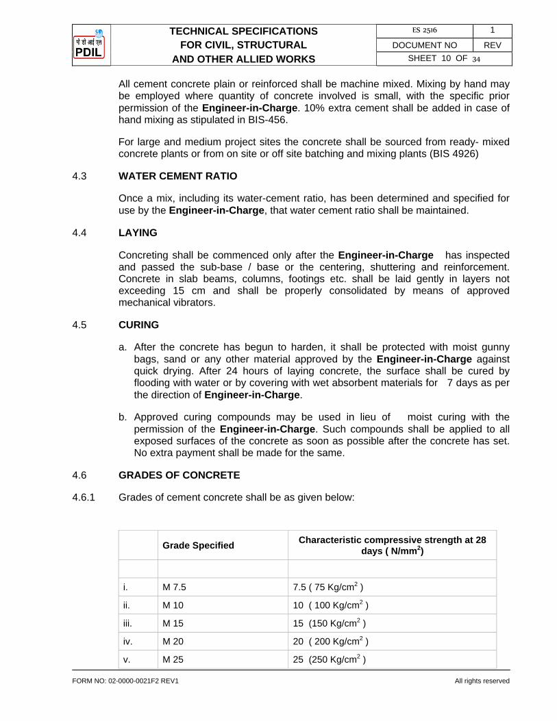
TECHNICAL SPECIFICATIONS ES 2516 1
FOR CIVIL, STRUCTURAL DOCUMENT NO REV
AND OTHER ALLIED WORKS SHEET 10 OF 34
FORM NO: 02-0000-0021F2 REV1 All rights reserved
All cement concrete plain or reinforced shall be machine mixed. Mixing by hand may be employed where quantity of concrete involved is small, with the specific prior permission of the Engineer-in-Charge. 10% extra cement shall be added in case of hand mixing as stipulated in BIS-456.
For large and medium project sites the concrete shall be sourced from ready- mixed concrete plants or from on site or off site batching and mixing plants (BIS 4926)
4.3 WATER CEMENT RATIO
Once a mix, including its water-cement ratio, has been determined and specified for use by the Engineer-in-Charge, that water cement ratio shall be maintained.
4.4 LAYING
Concreting shall be commenced only after the Engineer-in-Charge has inspected and passed the sub-base / base or the centering, shuttering and reinforcement. Concrete in slab beams, columns, footings etc. shall be laid gently in layers not exceeding 15 cm and shall be properly consolidated by means of approved mechanical vibrators.
4.5 CURING
a. After the concrete has begun to harden, it shall be protected with moist gunny bags, sand or any other material approved by the Engineer-in-Charge against quick drying. After 24 hours of laying concrete, the surface shall be cured by flooding with water or by covering with wet absorbent materials for 7 days as per the direction of Engineer-in-Charge.
b. Approved curing compounds may be used in lieu of moist curing with the permission of the Engineer-in-Charge. Such compounds shall be applied to all exposed surfaces of the concrete as soon as possible after the concrete has set. No extra payment shall be made for the same.
4.6 GRADES OF CONCRETE
4.6.1 Grades of cement concrete shall be as given below:
Grade Specified Characteristic compressive strength at 28 days ( N/mm2)
i. M 7.5 7.5 ( 75 Kg/cm2 )
ii. M 10 10 ( 100 Kg/cm2 )
iii. M 15 15 (150 Kg/cm2 )
iv. M 20 20 ( 200 Kg/cm2 )
v. M 25 25 (250 Kg/cm2 )
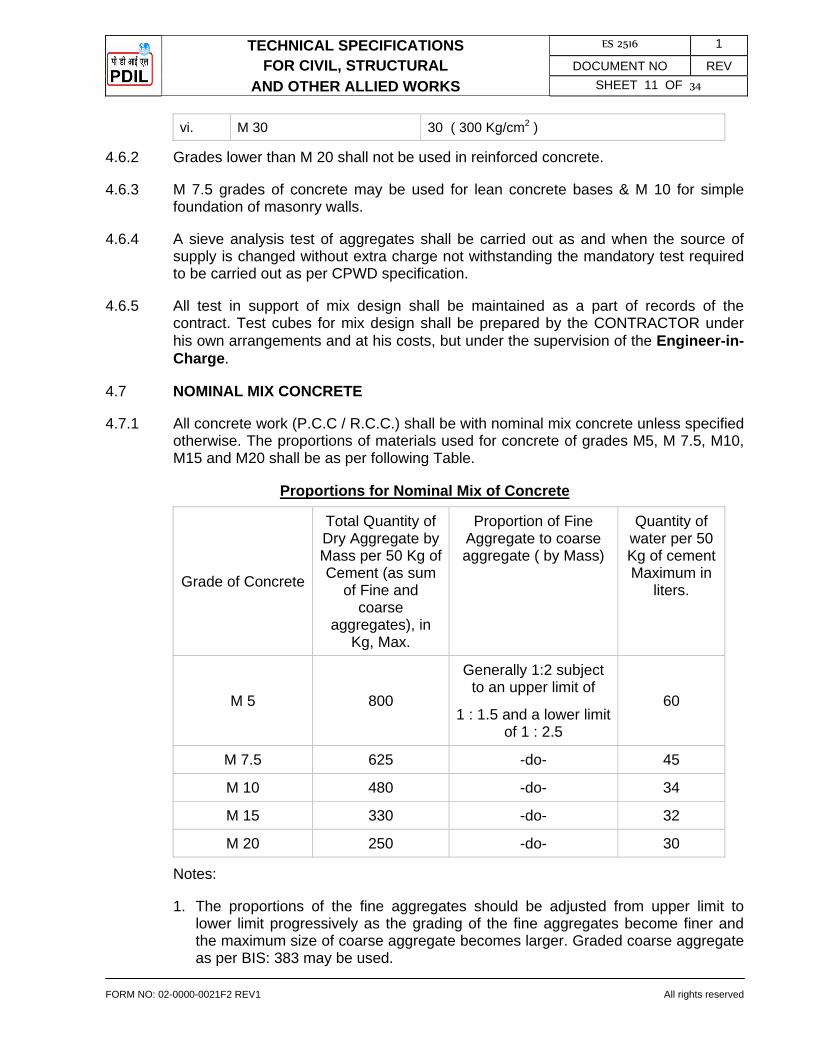
TECHNICAL SPECIFICATIONS ES 2516 1
FOR CIVIL, STRUCTURAL DOCUMENT NO REV
AND OTHER ALLIED WORKS SHEET 11 OF 34
FORM NO: 02-0000-0021F2 REV1 All rights reserved
vi. M 30 30 ( 300 Kg/cm2 )
4.6.2 Grades lower than M 20 shall not be used in reinforced concrete.
4.6.3 M 7.5 grades of concrete may be used for lean concrete bases & M 10 for simple foundation of masonry walls.
4.6.4 A sieve analysis test of aggregates shall be carried out as and when the source of supply is changed without extra charge not withstanding the mandatory test required to be carried out as per CPWD specification.
4.6.5 All test in support of mix design shall be maintained as a part of records of the contract. Test cubes for mix design shall be prepared by the CONTRACTOR under his own arrangements and at his costs, but under the supervision of the Engineer-in-Charge.
4.7 NOMINAL MIX CONCRETE
4.7.1 All concrete work (P.C.C / R.C.C.) shall be with nominal mix concrete unless specified otherwise. The proportions of materials used for concrete of grades M5, M 7.5, M10, M15 and M20 shall be as per following Table.
Proportions for Nominal Mix of Concrete
Grade of Concrete
Total Quantity of Dry Aggregate by Mass per 50 Kg of Cement (as sum
of Fine and coarse
aggregates), in Kg, Max.
Proportion of Fine Aggregate to coarse aggregate ( by Mass)
Quantity of water per 50 Kg of cement Maximum in
liters.
M 5 800
Generally 1:2 subject to an upper limit of
1 : 1.5 and a lower limit of 1 : 2.5
60
M 7.5 625 -do- 45
M 10 480 -do- 34
M 15 330 -do- 32
M 20 250 -do- 30
Notes:
1. The proportions of the fine aggregates should be adjusted from upper limit to lower limit progressively as the grading of the fine aggregates become finer and the maximum size of coarse aggregate becomes larger. Graded coarse aggregate as per BIS: 383 may be used.
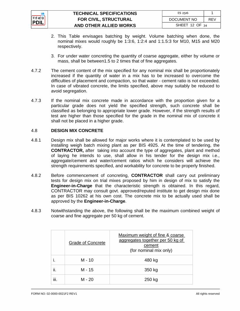
TECHNICAL SPECIFICATIONS ES 2516 1
FOR CIVIL, STRUCTURAL DOCUMENT NO REV
AND OTHER ALLIED WORKS SHEET 12 OF 34
FORM NO: 02-0000-0021F2 REV1 All rights reserved
2. This Table envisages batching by weight. Volume batching when done, the nominal mixes would roughly be 1:3:6, 1:2:4 and 1:1.5:3 for M10, M15 and M20 respectively.
3. For under water concreting the quantity of coarse aggregate, either by volume or mass, shall be between1.5 to 2 times that of fine aggregates.
4.7.2 The cement content of the mix specified for any nominal mix shall be proportionately increased if the quantity of water in a mix has to be increased to overcome the difficulties of placement and compaction, so that water - cement ratio is not exceeded. In case of vibrated concrete, the limits specified, above may suitably be reduced to avoid segregation.
4.7.3 If the nominal mix concrete made in accordance with the proportion given for a particular grade does not yield the specified strength, such concrete shall be classified as belonging to appropriate lower grade. However, if the strength results of test are higher than those specified for the grade in the nominal mix of concrete it shall not be placed in a higher grade.
4.8 DESIGN MIX CONCRETE
4.8.1 Design mix shall be allowed for major works where it is contemplated to be used by installing weigh batch mixing plant as per BIS 4925. At the time of tendering, the CONTRACTOR, after taking into account the type of aggregates, plant and method of laying he intends to use, shall allow in his tender for the design mix i.e., aggregate/cement and water/cement ratios which he considers will achieve the strength requirements specified, and workability for concrete to be properly finished.
4.8.2 Before commencement of concreting, CONTRACTOR shall carry out preliminary tests for design mix on trial mixes proposed by him in design of mix to satisfy the Engineer-in-Charge that the characteristic strength is obtained. In this regard, CONTRACTOR may consult govt. approved/reputed institute to get design mix done as per BIS 10262 at his own cost. The concrete mix to be actually used shall be approved by the Engineer-in-Charge.
4.8.3 Notwithstanding the above, the following shall be the maximum combined weight of coarse and fine aggregate per 50 kg of cement.
Grade of Concrete
Maximum weight of fine & coarse aggregates together per 50 kg of
cement (for nominal mix only)
i. M - 10 480 kg
ii. M - 15 350 kg
iii. M - 20 250 kg
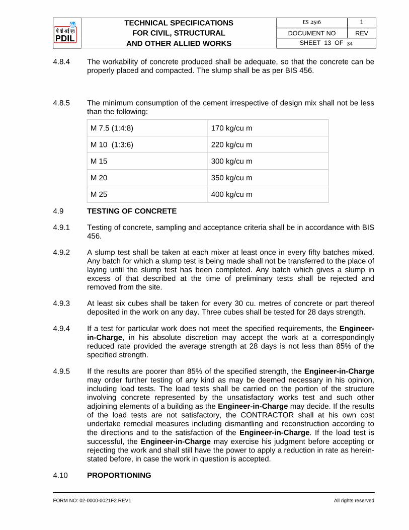
TECHNICAL SPECIFICATIONS ES 2516 1
FOR CIVIL, STRUCTURAL DOCUMENT NO REV
AND OTHER ALLIED WORKS SHEET 13 OF 34
FORM NO: 02-0000-0021F2 REV1 All rights reserved
4.8.4 The workability of concrete produced shall be adequate, so that the concrete can be properly placed and compacted. The slump shall be as per BIS 456.
4.8.5 The minimum consumption of the cement irrespective of design mix shall not be less than the following:
M 7.5 (1:4:8) 170 kg/cu m
M 10 (1:3:6) 220 kg/cu m
M 15 300 kg/cu m
M 20 350 kg/cu m
M 25 400 kg/cu m
4.9 TESTING OF CONCRETE
4.9.1 Testing of concrete, sampling and acceptance criteria shall be in accordance with BIS 456.
4.9.2 A slump test shall be taken at each mixer at least once in every fifty batches mixed. Any batch for which a slump test is being made shall not be transferred to the place of laying until the slump test has been completed. Any batch which gives a slump in excess of that described at the time of preliminary tests shall be rejected and removed from the site.
4.9.3 At least six cubes shall be taken for every 30 cu. metres of concrete or part thereof deposited in the work on any day. Three cubes shall be tested for 28 days strength.
4.9.4 If a test for particular work does not meet the specified requirements, the Engineer-in-Charge, in his absolute discretion may accept the work at a correspondingly reduced rate provided the average strength at 28 days is not less than 85% of the specified strength.
4.9.5 If the results are poorer than 85% of the specified strength, the Engineer-in-Charge may order further testing of any kind as may be deemed necessary in his opinion, including load tests. The load tests shall be carried on the portion of the structure involving concrete represented by the unsatisfactory works test and such other adjoining elements of a building as the Engineer-in-Charge may decide. If the results of the load tests are not satisfactory, the CONTRACTOR shall at his own cost undertake remedial measures including dismantling and reconstruction according to the directions and to the satisfaction of the Engineer-in-Charge. If the load test is successful, the Engineer-in-Charge may exercise his judgment before accepting or rejecting the work and shall still have the power to apply a reduction in rate as herein- stated before, in case the work in question is accepted.
4.10 PROPORTIONING
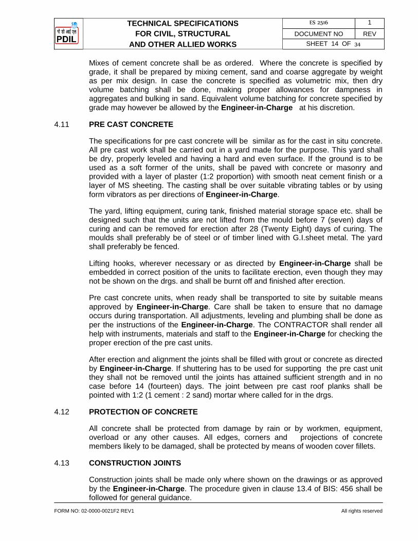
TECHNICAL SPECIFICATIONS ES 2516 1
FOR CIVIL, STRUCTURAL DOCUMENT NO REV
AND OTHER ALLIED WORKS SHEET 14 OF 34
FORM NO: 02-0000-0021F2 REV1 All rights reserved
Mixes of cement concrete shall be as ordered. Where the concrete is specified by grade, it shall be prepared by mixing cement, sand and coarse aggregate by weight as per mix design. In case the concrete is specified as volumetric mix, then dry volume batching shall be done, making proper allowances for dampness in aggregates and bulking in sand. Equivalent volume batching for concrete specified by grade may however be allowed by the Engineer-in-Charge at his discretion.
4.11 PRE CAST CONCRETE
The specifications for pre cast concrete will be similar as for the cast in situ concrete. All pre cast work shall be carried out in a yard made for the purpose. This yard shall be dry, properly leveled and having a hard and even surface. If the ground is to be used as a soft former of the units, shall be paved with concrete or masonry and provided with a layer of plaster (1:2 proportion) with smooth neat cement finish or a layer of MS sheeting. The casting shall be over suitable vibrating tables or by using form vibrators as per directions of Engineer-in-Charge.
The yard, lifting equipment, curing tank, finished material storage space etc. shall be designed such that the units are not lifted from the mould before 7 (seven) days of curing and can be removed for erection after 28 (Twenty Eight) days of curing. The moulds shall preferably be of steel or of timber lined with G.I.sheet metal. The yard shall preferably be fenced.
Lifting hooks, wherever necessary or as directed by Engineer-in-Charge shall be embedded in correct position of the units to facilitate erection, even though they may not be shown on the drgs. and shall be burnt off and finished after erection.
Pre cast concrete units, when ready shall be transported to site by suitable means approved by Engineer-in-Charge. Care shall be taken to ensure that no damage occurs during transportation. All adjustments, leveling and plumbing shall be done as per the instructions of the Engineer-in-Charge. The CONTRACTOR shall render all help with instruments, materials and staff to the Engineer-in-Charge for checking the proper erection of the pre cast units.
After erection and alignment the joints shall be filled with grout or concrete as directed by Engineer-in-Charge. If shuttering has to be used for supporting the pre cast unit they shall not be removed until the joints has attained sufficient strength and in no case before 14 (fourteen) days. The joint between pre cast roof planks shall be pointed with 1:2 (1 cement : 2 sand) mortar where called for in the drgs.
4.12 PROTECTION OF CONCRETE
All concrete shall be protected from damage by rain or by workmen, equipment, overload or any other causes. All edges, corners and projections of concrete members likely to be damaged, shall be protected by means of wooden cover fillets.
4.13 CONSTRUCTION JOINTS
Construction joints shall be made only where shown on the drawings or as approved by the Engineer-in-Charge. The procedure given in clause 13.4 of BIS: 456 shall be followed for general guidance.
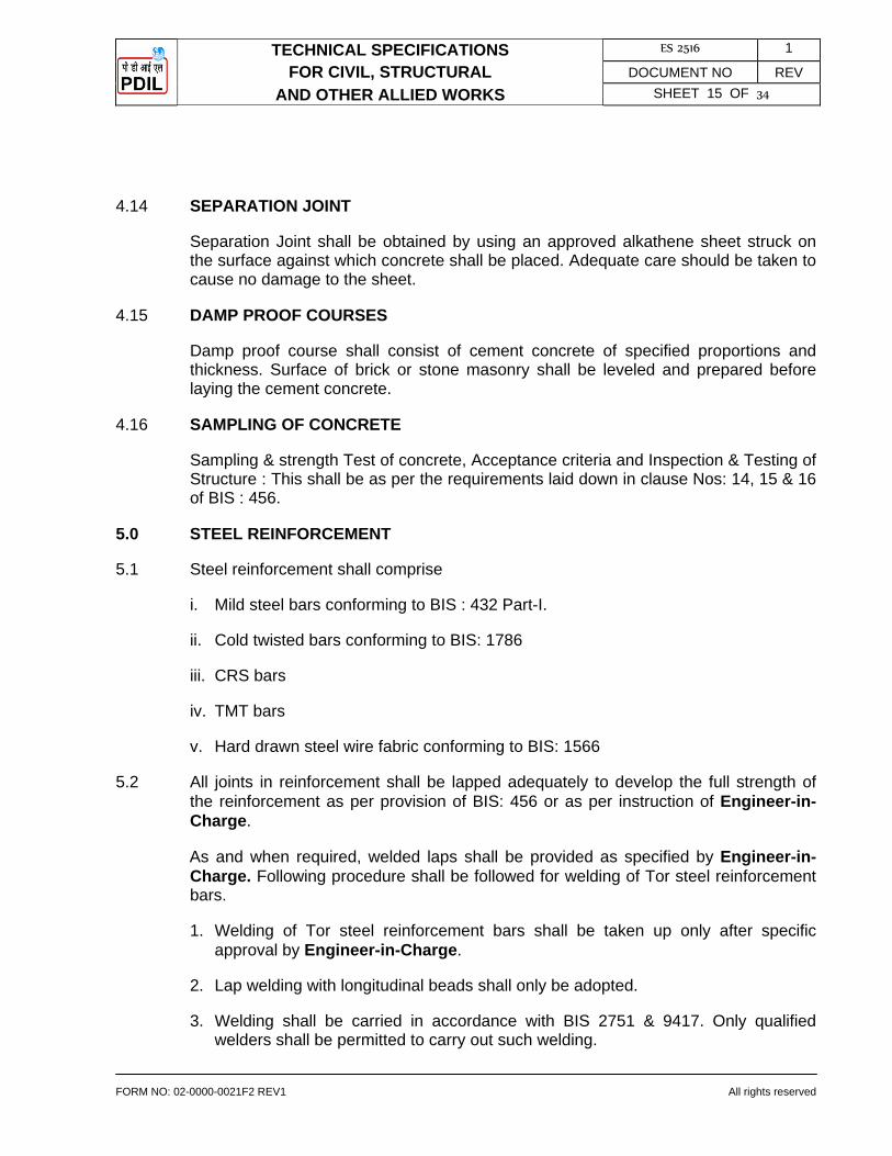
TECHNICAL SPECIFICATIONS ES 2516 1
FOR CIVIL, STRUCTURAL DOCUMENT NO REV
AND OTHER ALLIED WORKS SHEET 15 OF 34
FORM NO: 02-0000-0021F2 REV1 All rights reserved
4.14 SEPARATION JOINT
Separation Joint shall be obtained by using an approved alkathene sheet struck on the surface against which concrete shall be placed. Adequate care should be taken to cause no damage to the sheet.
4.15 DAMP PROOF COURSES
Damp proof course shall consist of cement concrete of specified proportions and thickness. Surface of brick or stone masonry shall be leveled and prepared before laying the cement concrete.
4.16 SAMPLING OF CONCRETE
Sampling & strength Test of concrete, Acceptance criteria and Inspection & Testing of Structure : This shall be as per the requirements laid down in clause Nos: 14, 15 & 16 of BIS : 456.
5.0 STEEL REINFORCEMENT
5.1 Steel reinforcement shall comprise
i. Mild steel bars conforming to BIS : 432 Part-I.
ii. Cold twisted bars conforming to BIS: 1786
iii. CRS bars
iv. TMT bars
v. Hard drawn steel wire fabric conforming to BIS: 1566
5.2 All joints in reinforcement shall be lapped adequately to develop the full strength of the reinforcement as per provision of BIS: 456 or as per instruction of Engineer-in-Charge.
As and when required, welded laps shall be provided as specified by Engineer-in-Charge. Following procedure shall be followed for welding of Tor steel reinforcement bars.
1. Welding of Tor steel reinforcement bars shall be taken up only after specific approval by Engineer-in-Charge.
2. Lap welding with longitudinal beads shall only be adopted.
3. Welding shall be carried in accordance with BIS 2751 & 9417. Only qualified welders shall be permitted to carry out such welding.
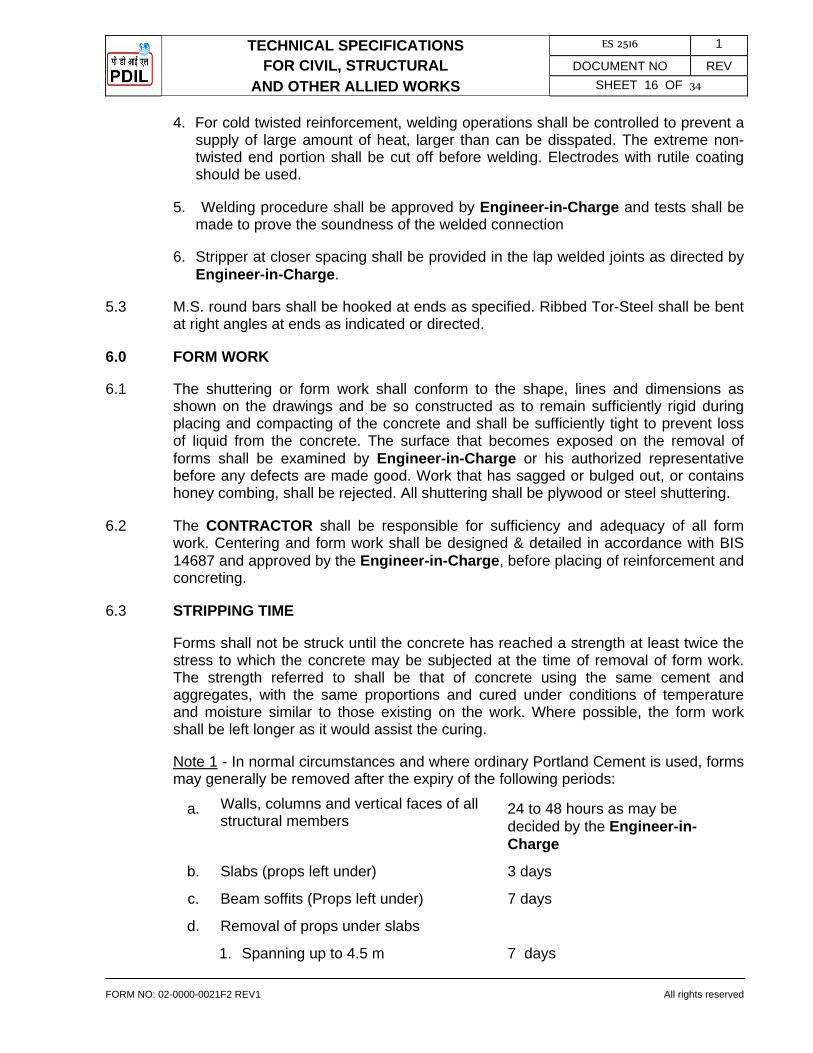
TECHNICAL SPECIFICATIONS ES 2516 1
FOR CIVIL, STRUCTURAL DOCUMENT NO REV
AND OTHER ALLIED WORKS SHEET 16 OF 34
FORM NO: 02-0000-0021F2 REV1 All rights reserved
4. For cold twisted reinforcement, welding operations shall be controlled to prevent a supply of large amount of heat, larger than can be disspated. The extreme non-twisted end portion shall be cut off before welding. Electrodes with rutile coating should be used.
5. Welding procedure shall be approved by Engineer-in-Charge and tests shall be made to prove the soundness of the welded connection
6. Stripper at closer spacing shall be provided in the lap welded joints as directed by Engineer-in-Charge.
5.3 M.S. round bars shall be hooked at ends as specified. Ribbed Tor-Steel shall be bent at right angles at ends as indicated or directed.
6.0 FORM WORK
6.1 The shuttering or form work shall conform to the shape, lines and dimensions as shown on the drawings and be so constructed as to remain sufficiently rigid during placing and compacting of the concrete and shall be sufficiently tight to prevent loss of liquid from the concrete. The surface that becomes exposed on the removal of forms shall be examined by Engineer-in-Charge or his authorized representative before any defects are made good. Work that has sagged or bulged out, or contains honey combing, shall be rejected. All shuttering shall be plywood or steel shuttering.
6.2 The CONTRACTOR shall be responsible for sufficiency and adequacy of all form work. Centering and form work shall be designed & detailed in accordance with BIS 14687 and approved by the Engineer-in-Charge, before placing of reinforcement and concreting.
6.3 STRIPPING TIME
Forms shall not be struck until the concrete has reached a strength at least twice the stress to which the concrete may be subjected at the time of removal of form work. The strength referred to shall be that of concrete using the same cement and aggregates, with the same proportions and cured under conditions of temperature and moisture similar to those existing on the work. Where possible, the form work shall be left longer as it would assist the curing.
Note 1 - In normal circumstances and where ordinary Portland Cement is used, forms may generally be removed after the expiry of the following periods:
a. Walls, columns and vertical faces of all structural members
24 to 48 hours as may be decided by the Engineer-in-Charge
b. Slabs (props left under) 3 days
c. Beam soffits (Props left under) 7 days
d. Removal of props under slabs
1. Spanning up to 4.5 m 7 days

TECHNICAL SPECIFICATIONS ES 2516 1
FOR CIVIL, STRUCTURAL DOCUMENT NO REV
AND OTHER ALLIED WORKS SHEET 17 OF 34
FORM NO: 02-0000-0021F2 REV1 All rights reserved
2. Spanning over 4.5 m 14 days
e. Removal of props under beams and arches :
1. Spanning up to 6 m 14 days
2. Spanning over 6m 21 days
For other types of cements, the stripling time recommended for ordinary Portland Cement may be suitably modified.
Note 2 - The number of props left under, their sizes and disposition shall be such as to be able to safely carry the full dead load of the slab, beam or arch as the case may be together with any live load likely to occur during curing or further construction.
7.0 BRICK WORK
This specification covers the construction of brick masonry in foundations, arches, walls, etc. at all elevations. The provision of BIS: 2212 shall be complied with unless permitted otherwise.
7.1 Bricks
All bricks shall conform to minimum class 7.5 as designated in CPWD Specifications unless specified otherwise.
7.2 Mortar
7.2.1 Cement and water shall conform to the requirements laid down for cement concrete work.
7.2.2 Sand for masonry mortar shall be coarse sand conforming to BIS: 2116. Maximum quantities of clay, fine dust shall not be more than 5% by weight. Organic impurities shall not exceed the limits laid down in BIS: 2116.
7.2.3 Mix of mortar for building brick work shall be as specified in the item of work.
7.2.4 Mixing of mortar shall be done in a mechanical mixer. When quantity involved is small, hand mixing may be permitted by the Engineer-in-Charge. Any mortar remaining unused for more than 30 minutes after mixing shall be rejected.
7.3 Brick Masonry
Brick work shall be built in English bond, unless otherwise specified. The thickness of joints shall be 10 mm + 3 mm. Thickness of joints shall be kept uniform. In case of foundations and manholes etc. Joints up to 15 mm may be accepted.
7.4 Half Brick Masonry
All courses shall be laid with stretchers. Reinforcement comprising 2 Nos.6 mm dia MS bars shall be provided over the top of the first course and thereafter at every third course.
TECHNICAL SPECIFICATIONS ES 2516 1
FOR CIVIL, STRUCTURAL DOCUMENT NO REV
AND OTHER ALLIED WORKS SHEET 18 OF 34
FORM NO: 02-0000-0021F2 REV1 All rights reserved
7.5 Fixtures
All iron fixtures, pipe spouts, hold fasts of doors and windows, which are required to be built into the wall shall be embedded in cement concrete blocks 1:2:4 mix (1 cement : 2 coarse sand : 4 graded stone aggregate 20 mm nominal size) of size indicated in the item.
7.6 Curing
Brick work shall be protected from rain by suitable covering when the mortar is green. Masonry work shall be kept constantly moist on all faces for a minimum period of seven days.
7.7 Cement Concrete Block
Cement concrete block shall be machined made in the proportion of such that mix shall not be leaner than one cement to Twelve combined aggregates ( by volume ) but having minimum strength of M 7.5. Combined aggregate shall be graded as near as possible to BIS : 383. The fineness modules of combined aggregate shall be between 3.6 and 4. The concrete block shall be properly cured as per BIS-456. The surface of conc. block shall have even face without any honeycomb and free from cracks.
7.7.1 Mortar
Cement and water shall confirm to the requirements laid down for cement concrete work.
7.7.2 Sand for concrete block masonry mortar's shall be coarse sand generally conforming to BIS: 2116. Maximum quantities of clay, fine dust, shall not be more than 5% by weight. Organic impurities shall not exceed the limits laid down in BIS: 2116.
7.7.3 Mix of mortar for building concrete block shall be as specified in the item of work.
7.7.4 Mixing of the mortar shall be done in a mechanical mixer. When quantity involved is small hand mixing may be permitted by Engineer-in-Charge. Any mortar remaining unused for more than 30 minutes after mixing shall be rejected.
7.8 Concrete Block Masonry
The thickness of joints shall be 10 mm +- 3mm. Thickness of joints shall be kept uniform. In case of foundation and manholes etc. joints up to 15 mm may be accepted.
7.9 Half Concrete Block
All courses shall be laid with stretchers. Reinforcement comprising 2 nos. 6 mm dia MS bars shall be provided over the top of the first course and thereafter at every fourth course.
7.10 Fixtures
TECHNICAL SPECIFICATIONS ES 2516 1
FOR CIVIL, STRUCTURAL DOCUMENT NO REV
AND OTHER ALLIED WORKS SHEET 19 OF 34
FORM NO: 02-0000-0021F2 REV1 All rights reserved
All iron fixtures, pipes spouts, hold fasts of doors and windows which are required to be built into the wall shall be embedded in cement concrete blocks 1:2:4 mix (1 cement :2 coarse sand :4 graded stone aggregate. 20 mm nominal size) of size indicated in the item.
7.11 Curing
Concrete block masonry shall be protected from rain by suitable covering when mortar is green. Masonry work shall be kept constantly moist on all faces for a minimum period of seven days.
8.0 WOOD WORK
All materials workmanship for wood work shall conform to BIS : 883, it shall be good quality well seasoned second class Teak / Sal wood as approved by Engineer-in-Charge. The wood work shall conform to BIS: 4021.
9.0 STRUCTURAL STEEL WORK
This specification covers the technical requirements for the preparation of shop drawings, supply, fabrication, protective coating, painting and erection of all structural steel rolled sections, built up sections, plates and miscellaneous steel required for the completion of the work.
9.1 Steel
All structural steel used in construction within the purview of this contract shall, comply with one of the following Bureau of Indian Standard Specifications, whichever, is appropriate or as specified.
BIS – 2062 Hot rolled sections and plates
BIS – 1079 Cold formed light gauge sections
BIS – 1161 Tubular sections
BIS – 4923 Hollow sections (rectangular or square)
9.2 Smithy Works
All smithy work shall be accurately made as shown on the drawings and shall be clean and sound. The metal shall not be burnt or injured in any way.
9.3 Fabrication
Fabrication of steel structure shall be carried out in conformity with the best modern practices and with due regard to speed with economy in fabrication and erection and shall conform to BIS-800. All members shall be so fabricated as to assemble the members accurately on site and erect them in correct positions. Before dispatch to site the components shall be assembled at shop and any defect found rectified. All members shall be free from kink, twist, buckle, bend, open joints etc. and shall be
TECHNICAL SPECIFICATIONS ES 2516 1
FOR CIVIL, STRUCTURAL DOCUMENT NO REV
AND OTHER ALLIED WORKS SHEET 20 OF 34
FORM NO: 02-0000-0021F2 REV1 All rights reserved
rectified before erecting in position. Failure in this respect will subject the defective members to rejection.
9.4 Fabrication Drawings
9.4.1 Fabrication and erection drawings shall be prepared by the CONTRACTOR on the basis of design issued to the CONTRACTOR in stages. These drawings shall be prepared by the CONTRACTOR or by an agency approved by the Engineer-in-Charge.
9.4.2 Fabrication drawings shall be thoroughly checked, stamped "checked" and signed by the CONTRACTOR's own responsible Engineer irrespective of the fact that such drawings are prepared by the CONTRACTOR or an approved agency, to ensure accuracy and correctness of the drawings. Unchecked or unsigned drawing shall not be submitted to Engineer-in-Charge for approval.
9.4.3 Fabrication drawings duly checked by the CONTRACTOR shall be submitted to the Engineer-in-Charge for checking & approval within 30 days from receipt of design drawings.
9.4.4 The approval accorded by Engineer-in-Charge on fabrication drawings shall not relieve the CONTRACTOR of the responsibility of fabricating and erecting safe and technically sound steel structures as per design drawings.
9.4.5 Fabrication drawings shall be drawn to a suitable scale large enough to convey the information clearly and shall include the following:
Reference to design drawing number (along with revision number) based on which fabrication drawing has been prepared.
Structural layout plans, elevations, & sections with distinct erections, & sections with distinct erection marking of all members.
Framing plans, member sizes, orientations.
Fabrication detail of each and every member.
Details of Shop / field joints, connections and splices.
Location, type and size of welds and bolts.
Shape and size of edge preparation for welding.
Bill of material including bolts for connections.
9.4.6 The CONTRACTOR shall however ensure accuracy of the following and shall be solely responsible for the same.
i. Provision for erection and erection clearance.
ii. Marking of members.
TECHNICAL SPECIFICATIONS ES 2516 1
FOR CIVIL, STRUCTURAL DOCUMENT NO REV
AND OTHER ALLIED WORKS SHEET 21 OF 34
FORM NO: 02-0000-0021F2 REV1 All rights reserved
iii. Cut length of members.
iv. Matching of joints and holes.
v. Provision kept in the members for other interconnected members.
vi. Bill of materials.
9.4.7 Connections, splices and other details where not shown on the design drawings shall be suitably designed and shown on the fabrication drawings based on good Engineering practice, developing full member strength.
9.4.8 The CONTRACTOR shall incorporate all the revisions in his fabrication drawings resulting from revision in design drawings during the course of execution of work at no extra cost.
9.4.9 The CONTRACTOR shall supply three (3) prints of each fabrication drawing submitted for checking to Engineer-in-Charge. After approval of fabrication drawings CONTRACTOR shall supply six (6) prints and two (2) reproducible of each approved fabrication drawing to Engineer-in-Charge. The rates quoted by the CONTRACTOR shall include the same.
9.5 Welding
Welding shall be adopted in most of the cases for fabrication of steel structure. Welding work shall be carried out as shown in relevant drawings as per BIS-816 or as required and approved by the Engineer-in-Charge. Welding of joints shall be so arranged that the resulting tensile and compressive stresses produced by each part of weld tend to balance each other.
The step back method of welding shall be adopted for continuous runs. Members which offer greater resistance to compression shall be welded first. The work shall be securely held in position by means of tack weld, clamps or jig before commencing of welding work so as to prevent relative movement due to distortion or other cause. All welds with blow holes, slag-intrusion and other defects must be removed from each run before another run is super imposed and also from the final run. Any defects in the work shall be rectified by the CONTRACTOR at his own expense. Bends, twists or distortion caused in any member due to faulty workmanship and method adopted during welding or in transit will be rejected and will have to be replaced / rectified by the CONTRACTOR at his own expense. According to the size of electrodes used, the CONTRACTOR is expected to adjust the current rating in the welding generators.
9.6 The Engineer-in-Charge reserves the right to have test done at any time for any welding and the cost of the test shall be borne by the CONTRACTOR.
9.7 Wherever continuous plates are used in built up member such as girders, columns, etc. the continuity of such plates shall be first ensured by full strength butt joints before welding such plates with the main member to form part of the built-up member.
9.8 All connection / joints made in shop shall wherever possible be welded connections and connections / joints made at site shall be bolted connections / site welded

TECHNICAL SPECIFICATIONS ES 2516 1
FOR CIVIL, STRUCTURAL DOCUMENT NO REV
AND OTHER ALLIED WORKS SHEET 22 OF 34
FORM NO: 02-0000-0021F2 REV1 All rights reserved
connections, continuous welding shall be done for all box members even if it is not required from design point of view.
9.9 Electrodes
Electrodes used for welding shall comply with BIS-814 or BIS - 815 or any specification provided to the CONTRACTOR from time to time. No electrodes remaining in open containers for more than 72 hours shall be used.
9.10 No welder shall be employed to carry out welding in any position except those who are fully qualified to weld in that position as per BIS -7318, part-1 qualifying tests for metal arc welders. Welders employed shall be required both before commencing work and at intervals during the progress of work to make test pieces as laid down in BIS -817 and 7318, part-1 for the purpose of grading of welders and according to the said grading, welders will be employed on jobs. Welders are to be got approved by Engineer-in-Charge before engaging on work.
9.11 MS Black/High Strength Bolts and Nuts
M.S.Black or high strength bolts, nuts and washers etc. shall be as per BIS-800, BIS-1363 and BIS-1367. Manufacturer's test certificate shall be made available to the Engineer-in-Charge or his representative, when called for. For bolted joints, shanks and threaded bolts are to be used to ensure that threaded length do not encroach within the thickness of connected members of dimension beyond the following limit:-
a. 1.5 mm for connected members of thickness below 12 mm and
b. 2.5 mm for connected member of thickness 12 mm and above and that adequate shearing and bearing values required as per design are achieved.
9.12 Every portion work shall have its erection mark or number stenciled on the member for guidance in erection and bears all necessary marks of erections as directed by the Engineer-in-Charge.
9.13 No part of the work is to be oiled, painted (except contact surfaces) packed, bundled, crated or dispatched until it has been finally inspected and approved by the Engineer-in-Charge or his authorized representative. The whole steel work before being dispatched from the CONTRACTOR's shop shall be dry and after being thoroughly cleaned from dust, mills scale, rust etc., and shall be given two coats of primer and one coat of final paint as per painting specification attached in this enquiry. Unless otherwise specified, all surfaces inaccessible after welding shall be given two coats of primer and two coats of paints as per painting specification Annexure attached in this enquiry.
9.14 The Engineer-in-Charge or his authorized representative shall have free access at all reasonable time to all places where the work is being carried out, and shall be provided by the CONTRACTOR at his own expenses all necessary facilities for inspection during fabrication and erection. The Engineer-in-Charge or his authorized representative shall be at liberty to reject the work in whole or in part if the workmanship or materials do not conform to the terms of the specifications mentioned
TECHNICAL SPECIFICATIONS ES 2516 1
FOR CIVIL, STRUCTURAL DOCUMENT NO REV
AND OTHER ALLIED WORKS SHEET 23 OF 34
FORM NO: 02-0000-0021F2 REV1 All rights reserved
herein. The CONTRACTOR shall remove, replace or, alter any part of the work as ordered by the Engineer-in-Charge or his authorized representative.
9.15 Erection and Setting of Steel Structure
The erection of steel work shall be in accordance with Bureau of Indian Standard Specifications Nos. BIS-800 and BIS - 816.
9.16 The CONTRACTOR shall be responsible for the suitability, safety and capabilities of all plant and equipment used for erection.
9.17 Prior to starting erection of fabricated structure, defects if any shall be rectified. The CONTRACTOR shall give to the Engineer-in-Charge not less than 24 hours notice of his intention to set out or give levels for any part of works, in order that arrangements may be made for checking. The CONTRACTOR shall provide all necessary arrangements and assistance which the Engineer-in-Charge may require for checking the setting out.
9.18 The CONTRACTOR shall erect the structural steel members in position, to dimension, and levels, as in relevant drawings and shall take care to see that component parts are not interchanged. Girders, stanchions etc., must rest fairly on their beds and will not be taken as erected until completely plumbed, aligned leveled, bolted or welded and strengthened, in every respect. The camber, if any, is to be maintained as shown in relevant drawings.
9.19 Particular care should be taken to ensure free expansion and contraction wherever provided in the relevant design / drawings or so directed on site.
9.20 While erecting, the holes in different component parts of structure should be made concentric with the use of drifts before any service bolts are fitted. No drifting shall be allowed except for bringing together several parts forming a member but the drifts must not be driven with such force as to disturb or damage the metal above the holes. Hammering of bolts to make holes concentric shall in no case be allowed. No nuts should be allowed to become loose and no unfilled bolt holes are to be left in any part of the structure unless otherwise specified in the relevant drawings. Welding should be adopted wherever specified in the drawings. Wooden rams or mallets shall be used in forcing members to position, in order to protect metal from injury or shocks, chipped edges shall be finished off smooth and all concave surface rounded off.
9.21 All erection tools and plants viz. derricks, cranes etc. will have to be provided by the CONTRACTOR as required in the erection work. All erection devices must be removed after the work is over, in such a way that no damage is done to the erected structures. Any damages, in this respect must be rectified by the CONTRACTOR at his own cost.
9.22 The maximum tolerance for line and level of the steel work shall be + 3.0 mm on any part of the structure. The structure shall not be out of plumb more than 3.5 mm on each 10 M. Section of height and not more than 7.0 mm per 30 metre section. These tolerances shall apply to all parts of the structure unless mentioned in the drawings issued for erection purposes.
TECHNICAL SPECIFICATIONS ES 2516 1
FOR CIVIL, STRUCTURAL DOCUMENT NO REV
AND OTHER ALLIED WORKS SHEET 24 OF 34
FORM NO: 02-0000-0021F2 REV1 All rights reserved
9.23 Match Marking & Stamping
i. All materials shall be match marked to facilitate erection.
ii. All pieces shall be stamped on at least two sides with erection marks as per fabrication drawings to facilitate identification on receipt and assembly.
10.0 PAINTING ON STRUCTURAL STEEL
The following specification shall be used for painting of structural steel work.
10.1 SCOPE
This specification shall be used in non coastal area.
Surface Preparation
The surfaces to be painted shall be sand blasted to Sa - 2.5 as per Swedish Standard SIS 05-59-00. Air used for sand blasting must be dry and oil free. Sand used for sand blasting shall be good quality river sand suitable for achieving the required surface finish. For optimum results pressure of sand blasting gun should be maintained at around 7 kg/cm2 and maximum height of profile should be kept around 50 microns. Sand blasted surfaces must be coated with primer within 4 hrs in dry climate. Moreover it is not advisable to carry out sand blasting when humidity exceeds 85% (RH).
10.1.1 Painting system to be used are indicated below:
a. Epoxy Painting:
Primer P 1-2 coats + finish paint FP1 (2 coats) where P1 is epoxy polyamide cured zinc chromate primer having DFT of 35 micron per coat and FP1 is epoxy polyamide cured finish paint having DFT (Dry Film Thickness) of 35 micron per coat.
b. For chlorinated rubber paint.
Primer P2 - 2 coats - finish paint FP2 - 2 coats. Where P2 is high chlorinated zinc phosphate primer having DFT of 50 microns per coat and FP2 is chlorinated rubber based paint having DFT of 50 microns per coat.
10.1.2 Equivalent product chart for approved paint manufactures for primer P1 and P2 finish paint FP1 and FP2 indicated above is enclosed.
10.1.3 All the surfaces must be sand blasted and 2 coats of primer plus 1 coat of finish paint applied in the shop before the same are shifted to site for erection. All the members must be suitably match marked for facilitating proper assembly.
After erection is over all surfaces shall be washed up as follows:

TECHNICAL SPECIFICATIONS ES 2516 1
FOR CIVIL, STRUCTURAL DOCUMENT NO REV
AND OTHER ALLIED WORKS SHEET 25 OF 34
FORM NO: 02-0000-0021F2 REV1 All rights reserved
a. Washing with clean water (pressure 7 kg/cm2) using suitable nozzles. During washing broom corn brushes shall be used to remove foreign matters.
b. Solvent washing if required to remove traces of oil grease etc.
After washing the surface as indicated above, the surfaces shall be suitably touched up to the extent required so that all the damages to the premiered surfaces caused during erection are done up.
The surfaces affected by welding and / or gas cutting during erection shall also be suitably touched up. Before touch up is taken up surfaces shall be prepared by mechanical means such as grinding, power brushing etc. to achieve surface finish to ST-3.
After touch up work is over as indicated above, all the surfaces shall be given one coat of finish paint to the required specification.
10.1.4 The following points must be observed for painting work:
a. Primer and paint shall be compatible to each other and should be from the same manufacturer.
b. The recommendation of the paint manufacturer regarding mixing, matching and application must be followed meticulously.
c. Technical representative of paint manufacturer should be available at site as and when required by Engineer-in-Charge for their expert advice as well as to ensure that the painting work is executed as per the instruction of paint manufactures.
Paints and primers shall be supplied at site in original container with factory seal otherwise such paints and primers shall not be allowed to be used. Mode of application i.e. by spray, brush or roller shall be strictly as per recommendation of paint manufacturer.
Painting materials must be used before the expiry date indicated on the containers.
Number of coats and DFT per coat must be strictly followed as indicated above. If the desired DFT is not achieved for primer and finish paints in two coats (each), CONTRACTOR shall be required to apply extra coat (s) to achieve the desired DFT without any extra cost to Engineer-in-Charge.
Colour shade for each coat of primer and finish paint must be different to identify the coats without any ambiguity.
Shade for the final finish coat shall be decided by Engineer-in-Charge at site.
All painting materials must be accompanied by manufacturers test certificates. However, Engineer-in-Charge has any doubt regarding quality of materials, he
TECHNICAL SPECIFICATIONS ES 2516 1
FOR CIVIL, STRUCTURAL DOCUMENT NO REV
AND OTHER ALLIED WORKS SHEET 26 OF 34
FORM NO: 02-0000-0021F2 REV1 All rights reserved
shall have the right to direct CONTRACTOR to get the doubtful material tested or and provided (by CONTRACTOR) testing agencies for which no extra payment shall be made to the CONTRACTOR and the charges shall deemed to be covered in the unit rates quoted for fabrication and erection of structural work.
DFT for paint shall be measured at least 20 points and mean DFT shall not vary by more than 10% than specified in DFT.
Instrument for measurement of DFT shall be arranged and provided by CONTRACTOR at his cost.
Thickness of each coat shall also be checked regularly to ensure uniformity in DFT.
10.1.5 Measurement
For purpose of payment, structural work so painted shall be measured and paid on MT basis. The weight for this item shall be taken from any of the following documents in the following order of priority:
i. Weights mentioned on the approved drawings.
ii. Weights paid to fabrication CONTRACTOR for structural fabrication work.
10.1.6 Sand blasting and painting works, being a specialized job must be carried out through the approved agencies only.
10.1.7 EQUIVALENT CHART FOR VARIOUS PAINT MANUFACTURERS
ASIAN G & N SHALIMAR J & N BERGER BOMBAY
P1 APCODUR - Epoxy Zinc Chrome Primer
AMERCOAT-71
EPIGARD-4 ZINC CHROMATE PRIMER
EPILAC ZINC CHROMATE PRIMER
EPILUX-4 ZINC CHROMATE PRIMER
PENTADUR PRIMER 1532
P2 ASIOCHLOR HB ZINC PHOSPHATE PRIMER
NEROLAC PHOSPHATE PRIMER
CHLOROKOTE ZINC PHOSPHATE PRIMER
JENSOLAC CR PRIMER
LINOSOL HB ZINC PHOSPHATE PRIMER
KANGAROO HB ZINC PHOSPHATE OR HEMPATEX PRIMER 1632
FP1 APCODUR CF 692
NEROLAC TWO COMP EPOXY
EPIGARD XL FINISH
EPILAC 974 ENAMEL
EPILUX-4 ENAMEL
PENTADUR ENAMEL 5534 GRAY
FP2 ASIOCHLOR CF 625
NEROLAC CR PAINT
CHLOROKOTE FINISH
JENSOLAC CHLORINATD. RUBR. PAINT
LINSOL CHLORINATED RUBR.PAINT
PENTACHLOR GP ENAMEL 5638
10.2 SCOPE

TECHNICAL SPECIFICATIONS ES 2516 1
FOR CIVIL, STRUCTURAL DOCUMENT NO REV
AND OTHER ALLIED WORKS SHEET 27 OF 34
FORM NO: 02-0000-0021F2 REV1 All rights reserved
This specification shall be used for the painting of structural steel in coastal area in saline atmosphere.
10.2.1 SURFACE PREPARATION
Surface preparation for all items to be painted shall be done by sand blasting to Sa 2.5 as per Swedish Specification SIS 05-59-00. Air used for sand blasting must be dry and oil free. Sand used for sand blasting must be of good quality river sand suitable for achieving required surface finish for optimum results. Pressure at sand blasting gun should be maintained at around 7 kg/cm2 and max. height of profile should be kept around 50 microns.
Sand blasted surfaces must be coated with primer within 2 hrs in dry climate. Moreover it is not advisable to carry out sand blasting when humidity exceeds 50% RH.
10.2.2 Painting systems to be used are as indicated below:-
a. FOR UNPAINTED SURFACES
i. P1-One coat of Ethyl silicate inorganic zinc primer having DFT of 70 microns per coat.
ii. IP1-One coat of Epoxy MIO having DFT of 70 microns per coat. iii. FP-1 One coat of finish epoxy paint using two pack Polyamide cured epoxy
having DFT of 40 microns per coat. iv. FP-2 One coat of Aliphatic Acrylic Polyurethane paint having DFT of
40microns per coat. 10.2.3 The following points must be observed for painting work:-
a. Only the approved paints/primers as indicated in the equivalent product chart (attached herewith) are to be used.
b. All the surfaces must be sand blasted and one coat of primer including one coat
of MIO are to be applied in the fabrication shop at project site before lifting the components for erection. After erection is over all the surfaces must be washed as indicated below:-
i. Wash with clean water (pressure approx. 7 kg/cm2) using suitable nozzles.
During washing, broom corn brushes to be used to remove foreign matter, if any.
ii. Solvent washing if felt necessary to remove traces of oil, grease etc. iii. After washing surfaces as indicated above, shall be suitably touched up to the
extent required, so that all the damages to the primed surfaces caused during erection are taken care off.
TECHNICAL SPECIFICATIONS ES 2516 1
FOR CIVIL, STRUCTURAL DOCUMENT NO REV
AND OTHER ALLIED WORKS SHEET 28 OF 34
FORM NO: 02-0000-0021F2 REV1 All rights reserved
c. Surfaces effected by welding and/or gas cutting or handling during erection shall also be suitably touched up after preparing the damaged surfaces by mechanical means such as grinding, power brushing etc. to achieve surface finish to ST-3.
d. Application of ethyl silicate inorganic zinc primer must be under taken by spray method. Other application methods such as brush/roller application are not permitted.
e. Primers and paints for a particular system must be purchased from same manufacturer for compatibility.
f. Recommendation of the paint manufacturer regarding mixing, maturing, application (except as indicated specially in this specification) must be followed meticulously.
g. Technical representative of the paint manufacturers at site must be made available as and when required by PDIL for their expert advise as well as to ensure that painting work is executed as per instructions of paint manufacturer.
h. All paints, primers must be supplied to site in original containers with factory seal. Otherwise paints, primers shall not be allowed to used.
i. Mode of application for other primers and paints except ethyl silicate inorganic zinc primer shall be strictly as per recommendation of paint manufacturer.
j. All painting materials should be consumed within expiry date indicated by manufacturers on the containers.
k. Number of coat and DFT per coat must be strictly followed as indicated in the specification above and if the desired DFT is not achieved in the specified number of coat, CONTRACTOR shall be required to apply extra coat(s) to achieve desired DFT without any additional cost to PDIL/owner. It may be noted here that multi coat is not allowed for ethyl silicate inorganic zinc primer and therefore extreme care is to be taken for assuring desired DFT in single coat.
Unless it is not practical to do so, colour shades for primer, intermediate coat and finish paints must be different to identify each coat without any ambiguity.
l. All painting materials must be accompanied by manufacturers test certificate. However, if PDIL has any reasonable doubt regarding quality of the materials then, CONTRACTOR shall be required to get doubtful materials tested by PDIL approved testing agencies and nothing extra shall be paid for carrying out above testing and testing charges shall be deemed to be included in the rates quoted for painting work.
m. DFT for painting shall be measured at least 20 points and mean DFT shall not vary by more than 10% of the specified DFT.
Reliable and calibrated instrument for measurement of DFT shall be arranged and provided by CONTRACTOR at his cost at site.
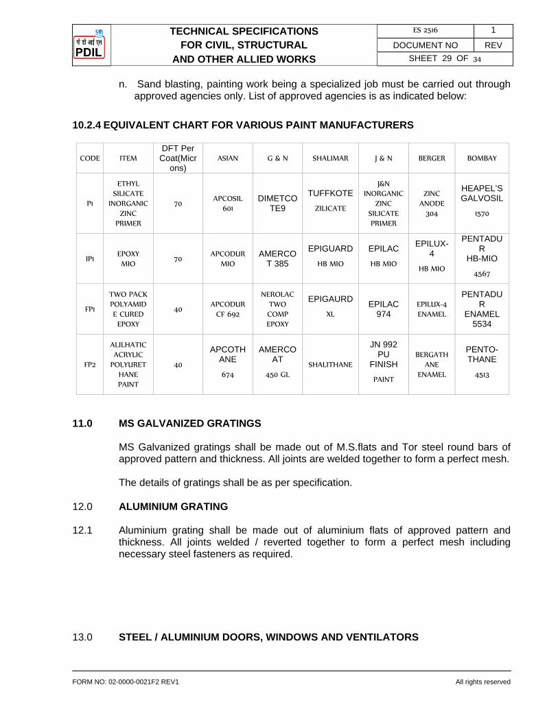
TECHNICAL SPECIFICATIONS ES 2516 1
FOR CIVIL, STRUCTURAL DOCUMENT NO REV
AND OTHER ALLIED WORKS SHEET 29 OF 34
FORM NO: 02-0000-0021F2 REV1 All rights reserved
n. Sand blasting, painting work being a specialized job must be carried out through approved agencies only. List of approved agencies is as indicated below:
10.2.4 EQUIVALENT CHART FOR VARIOUS PAINT MANUFACTURERS
CODE ITEM DFT Per
Coat(Microns)
ASIAN G & N SHALIMAR J & N BERGER BOMBAY
P1
ETHYL SILICATE
INORGANIC ZINC
PRIMER
70 APCOSIL
601 DIMETCO
TE9
TUFFKOTE
ZILICATE
J&N INORGANIC
ZINC SILICATE PRIMER
ZINC ANODE
304
HEAPEL’S GALVOSIL
1570
IP1 EPOXY MIO
70 APCODUR
MIO AMERCO
T 385
EPIGUARD
HB MIO
EPILAC
HB MIO
EPILUX-4
HB MIO
PENTADUR
HB-MIO
4567
FP1
TWO PACK POLYAMIDE CURED EPOXY
40 APCODUR
CF 692
NEROLAC TWO COMP EPOXY
EPIGAURD
XL EPILAC
974 EPILUX-4 ENAMEL
PENTADUR
ENAMEL 5534
FP2
ALILHATIC ACRYLIC
POLYURETHANE PAINT
40
APCOTHANE
674
AMERCOAT
450 GL SHALITHANE
JN 992 PU
FINISH
PAINT
BERGATHANE
ENAMEL
PENTO- THANE
4513
11.0 MS GALVANIZED GRATINGS MS Galvanized gratings shall be made out of M.S.flats and Tor steel round bars of
approved pattern and thickness. All joints are welded together to form a perfect mesh. The details of gratings shall be as per specification. 12.0 ALUMINIUM GRATING 12.1 Aluminium grating shall be made out of aluminium flats of approved pattern and
thickness. All joints welded / reverted together to form a perfect mesh including necessary steel fasteners as required.
13.0 STEEL / ALUMINIUM DOORS, WINDOWS AND VENTILATORS

TECHNICAL SPECIFICATIONS ES 2516 1
FOR CIVIL, STRUCTURAL DOCUMENT NO REV
AND OTHER ALLIED WORKS SHEET 30 OF 34
FORM NO: 02-0000-0021F2 REV1 All rights reserved
13.1 The Steel doors, windows, ventilators and sashes shall be of the size and type as shown on the drawings and/or of the approved make conforming to BIS-1361 and BIS-1038 Fixing and glazing shall be done as per BIS-1081 and as per manufacturers instructions. The putty of approved make such as special gold size or equivalent conforming to BIS-419 shall be used.
13.2 Aluminium doors, windows and ventilators shall be manufactured from wrought
aluminium and aluminium alloy extruded round tube and / or hollow rectangular / square sections conforming to BIS: 1285 & BIS : 6477 or equivalent as approved by Engineer-in-Charge.
14.0 NON-ASBESTOS HIGH IMPACT POLYPROPYLENE REINFORCED CEMENT
CORRUGATED SHEETS FOR ROOFING AND CLADDING
All non asbestos high impact polypropylene reinforced cement 6mm thick corrugated sheets shall be of the specified approved quality and shall be in accordance with IS-14871 and fixing accessories such as J-bolts, L-bolts, roofs washers, etc. shall conform to BIS-730. Laying and fixing of sheets used as covering for roofs and wall shall conform to BIS-3007 part-I. Holes for receiving the fixing accessories in the crown of corrugation must be drilled and not punched and diameter should be 3 mm greater than the diameter of the bolts to be used. Bolts and screws should be 8 mm or more in dia. and the nuts of the hook bolts, crank bolts should bear a gal vanished iron limpet washers. The screw or bolts should be tightened sufficiently only to seat the bitumen washer over the corrugations so that the natural movement in the substructure of the roof may not damage sheeting. It is essential that the bolt holes are made water tight by the use of bitumen washers in conjunction with suitable G.I.washer. These form essential accessories to good fixing work. A cracked sheet should never be used.
15.0 FLOORING AND PAVING 15.1 Sub Base of floor 15.1.1 The area to be paved shall be divided into suitable panels. Form work shall be
provided. The boarding / battens shall be fixed in position with their toe at proper level, giving slope where required. Alternatively base concrete may be deposited in the whole area at a stretch.
15.1.2 Before placing the base concrete the sub-base shall be properly wetted and rammed.
The concrete of the specified mix shall then be deposited between the forms where provided, thoroughly tamped and the surface finished level with the top edge of the forms. The surface of base concrete shall be spreader uniformly. The surface shall be finished rough to provide adequate bond for the topping. Two or three hours after concrete has been laid the surface shall be brushed with wire brush to remove any scum or Latinate and swept clean so that coarse aggregate is exposed.
15.2 Cement Concrete Floor Finish

TECHNICAL SPECIFICATIONS ES 2516 1
FOR CIVIL, STRUCTURAL DOCUMENT NO REV
AND OTHER ALLIED WORKS SHEET 31 OF 34
FORM NO: 02-0000-0021F2 REV1 All rights reserved
15.2.1 The surface of base concrete shall be thoroughly cleaned by scrubbing with coir or steel wire brush. Before laying the toping, the surface shall be soaked with water at least for 12 hours and surplus water mopped up immediately before the toping is laid.
15.2.2 The forms shall be fixed over the base concrete dividing into suitable panels. Where
glass dividing strips are provided, thickness of glass dividing strips shall be 4 or as indicated. Before placing the concrete toping, neat cement slurry at the rate of 2 kg/sq.m shall be then thoroughly brushed into the base concrete just ahead of the finish. The topping shall then be laid, thoroughly compacted by using screed board/plate vibrator. The surface floated with a wooden float to a fair and even surface shall be left for some time till moisture disappears from it. Junctions with skirting / dado or wall surfaces shall be rounded off using cement mortar 1:2 curing shall be carried out for a minimum of 7 days.
16.0 PLASTERING 16.1 Sand for plastering : shall be 50% fine sand and 50% coarse sand from approved
sources. 16.2 Preparation of surface shall be done as per CPWD specifications. 16.3 Cement mortar shall be of the mix as indicated in the items and shall be mixed as
specified in the CPWD specifications. 16.4 Joints in walls etc. shall be raked to a depth of 12 mm, brushed clean with wire
brushes dusted and thoroughly washed before starting the plaster work. 16.5 The surface shall be thoroughly washed with water cleaned and kept wet to saturation
point before plastering is commenced. 16.6 Cement mortar as indicated, shall be firmly applied to the masonry walls in a uniform
layer to the thickness specified and will be pressed into the joints. On concrete surfaces rendering shall be dashed to the roughened surface to ensure adequate bond. The surface shall be finished even and smooth. Hectoring wherever required shall be done as per directions of Engineer-in-Charge. Nothing extra shall be paid on this account.
16.7 All plaster work shall be cured for at least 7 days. 16.8 Integral water proofing compound shall be mixed with cement in the proportion
recommended by the manufacturer. Care shall be taken to ensure that the water proofing material gets well and integrally mixed with cement. All other operations are the same as for general plaster work.
16.9 For sand face plaster undercoat of cement plaster 1:4 (1 cement : 4 sand) of
thickness not less than 12 mm shall be applied similar to one coat plaster work. Before the under coat hardens the surface shall be scared to provide for the top coat. The top coat also of cement mortar 1:4 shall be applied to a thickness not less than 8 mm and brought to an even surface with a wooden float. The surface shall then be

TECHNICAL SPECIFICATIONS ES 2516 1
FOR CIVIL, STRUCTURAL DOCUMENT NO REV
AND OTHER ALLIED WORKS SHEET 32 OF 34
FORM NO: 02-0000-0021F2 REV1 All rights reserved
tapped gently with a wooden float lined with cork to retain a coarse surface texture, care being taken that the tapping is even and uniform.
17.0 WHITE & COLOUR WASHING AND CEMENT PAINTING 17.1 White Washing 17.1.1 Where white wash is indicated, 3 coats of white wash shall be applied. The surface
shall present a smooth and uniform finish. 17.1.2 White wash shall be prepared from lime slaked at site and mixed and stirred with 5
litres of water for one kg. of unsalted lime to make a thin cream. The cream shall be screened through a clean, coarse cloth and suitable adhesive such as DDL or equivalent as per manufacturer specification. About 1.3 kg of sodium chloride in hot water shall also be added for every 10 kg. of lime for making the coat hard and rule resistant. Indigo shall also be mixed @ 3 gm/Kg of lime. Each, coat shall be allowed to dry before next coat is applied. When dry, the wash should show no sign of cracking. One coat consists of application with brushes in horizontal stroke followed by vertical stroke.
17.2 Colour Washing 17.2.1 Where colour wash is indicated, one coat of white wash and two coats of colour of
tints approved by the Engineer-in-Charge shall be applied. Dados and skirting shall not be white washed, colour washed or distempered or painted.
17.2.2 Only Colour stainer of approved brand not affected by lime, shall be added to colour
wash. Indigo (Neel) shall, however, not be added in colour wash. 17.2.3 The colour wash shall be applied as described for white wash. After the surface has
been prepared the first primary coat shall be of white wash. Minimum two coats of colour wash shall then be applied. The entire surface shall present a smooth and uniform finish of even tint or shade.
17.3 Distempering 17.3.1 Where distempering is indicated, two coats of distemper oil emulsion or dry distemper
over a priming coat as specified in the item shall be applied. Each coat of distemper shall be approved by the Engineer-in-Charge before next coat is applied.
17.3.2 Distemper oil emulsion shall be as per BIS: 248 of approved brand and manufacture.
The distemper shall be diluted with water or a prescribed thinner in the proportion of 4 parts of paste by weight to one part of cold water or in the proportion specified by the manufacturer, which shall be invariably followed.
17.3.3 The surface to be distempered shall be cleaned of dust, dirt, chalking and other
foreign matter. All cracks, holes and surface defects shall be repaired with gypsum to give a smooth surface, and papered and wiped clean. The surface shall then be rubbed down again with sand paper and made smooth. The surface thus prepared
TECHNICAL SPECIFICATIONS ES 2516 1
FOR CIVIL, STRUCTURAL DOCUMENT NO REV
AND OTHER ALLIED WORKS SHEET 33 OF 34
FORM NO: 02-0000-0021F2 REV1 All rights reserved
shall be given a coat of alkali resistant, priming paint conforming to BIS: 109 or any other primer as specified by the manufacturer and allowed to dry at least for 48 hours.
17.3.4 Dry distemper shall be of approved make and shade conforming to BIS 427 and
shall be prepared as per manufacturer's specification. The surface to be distempered shall be cleaned of dust, dirt, chalking and other foreign matter. All cracks, holes and surface defects shall be repaired with gypsum to give a smooth surface, and papered and wiped clean. The surface shall then be rubbed down again with sand paper and made smooth. The surface thus prepared shall be given a coat of alkali resistant, priming paint conforming to BIS: 109 or any other primer as specified by the manufacturer and allowed to dry at least for 48 hours.
17.3.5 After the primer coat has dried for at least 48 hours, the surface shall be lightly sand
papered to make it smooth for receiving the distemper, taking care not to rub cut the priming coat and then dusted off. Prepared distemper shall then be applied with brushes in horizontal strokes followed immediately by vertical ones which together constitute one coat.
17.3.6 Subsequent coats shall be applied in the same way, with time intervals of at least 24
hours between consecutive coats. 17.3.7 A uniform finished surface without patches, brush marks, or distemper drops shall be
obtained. 17.4 Cement Painting 17.4.1 Cement paint: Cement paint shall comply with BIS: 5410 specification for cement
paint, of colour as required. 17.4.2 Where shown on drawings for external surfaces of sand faced plaster, or any other
surface, two coats of cement paint shall be applied of tint and shade as approved by the Engineer-in-Charge.
17.4.3 The surfaces shall be prepared as specified for white washing. Before applying
cement paint the surface shall be thoroughly wetted to control surface suction. The surface shall be moist but not dripping wet, when the paint is applied. Not less than 24 hours shall be allowed between the two coats. In hot weather the first coat shall be slightly moistened before applying the second coat.
17.4.4 On external plastered surfaces, sand faced or plain plastered and concrete surfaces,
cement paint shall be vigorously scrubbed on to work the paint into the voids and provide a continuous paint film free from pin holes and other openings. Curing shall be done between the coats and for at least 2 days following the final coat.
18.0 GLAZING 18.1 Sheet glass glazing of doors, windows etc. shall be of selected quality glass
conforming to BIS: 2835. Toughened splinter proof industrial safety glass shall confirm to BIS: 2553. No cracked chipped or disfigured glass shall be accepted Glass shall be in one piece for each pan.

TECHNICAL SPECIFICATIONS ES 2516 1
FOR CIVIL, STRUCTURAL DOCUMENT NO REV
AND OTHER ALLIED WORKS SHEET 34 OF 34
FORM NO: 02-0000-0021F2 REV1 All rights reserved
18.2 Glazing shall be fixed with timber or steel / aluminium beading as called for. Glass
shall be back puttied and fixed with beading for a water tight and rattle free installation. Sizes of timber/ steel / aluminium beading shall be as directed.
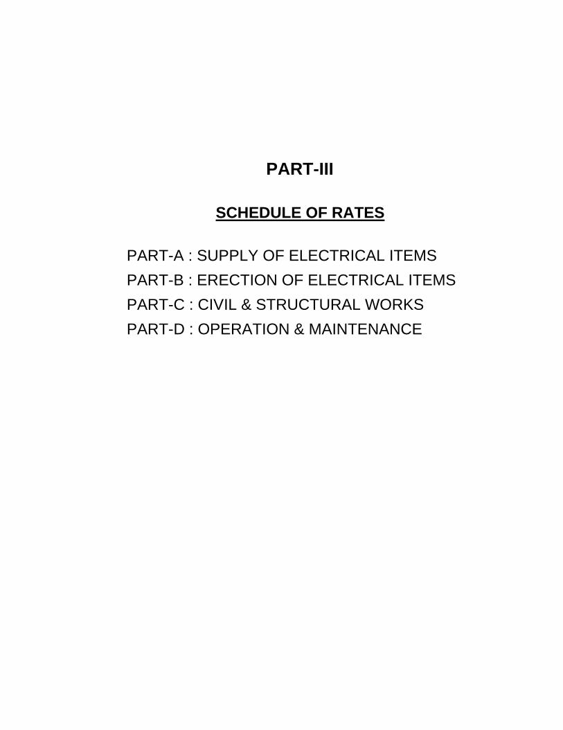
PART-III
SCHEDULE OF RATES
PART-A : SUPPLY OF ELECTRICAL ITEMS PART-B : ERECTION OF ELECTRICAL ITEMS PART-C : CIVIL & STRUCTURAL WORKS PART-D : OPERATION & MAINTENANCE
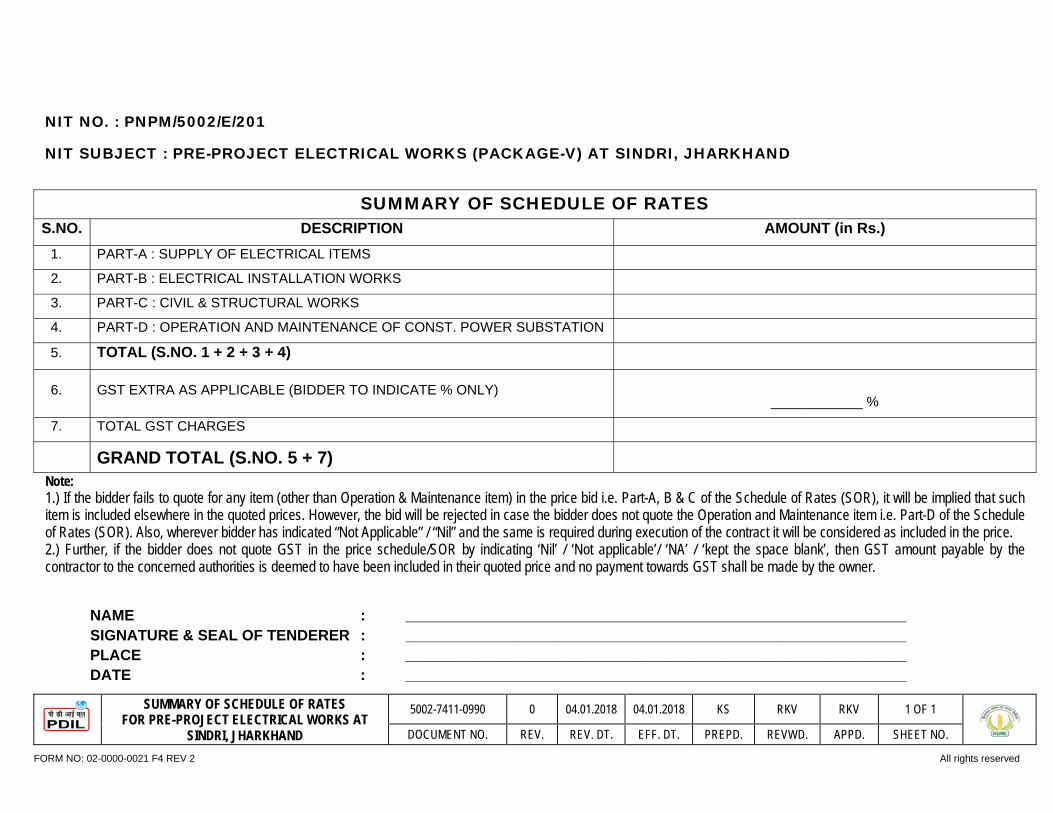
SUMMARY OF SCHEDULE OF RATES FOR PRE-PROJECT ELECTRICAL WORKS AT
SINDRI, JHARKHAND
5002-7411-0990 0 04.01.2018 04.01.2018 KS RKV RKV 1 OF 1
DOCUMENT NO. REV. REV. DT. EFF. DT. PREPD. REVWD. APPD. SHEET NO.
FORM NO: 02-0000-0021 F4 REV 2 All rights reserved
NIT NO. : PNPM/5002/E/201
NIT SUBJECT : PRE-PROJECT ELECTRICAL WORKS (PACKAGE-V) AT SINDRI, JHARKHAND
SUMMARY OF SCHEDULE OF RATES S.NO. DESCRIPTION AMOUNT (in Rs.)
1. PART-A : SUPPLY OF ELECTRICAL ITEMS
2. PART-B : ELECTRICAL INSTALLATION WORKS
3. PART-C : CIVIL & STRUCTURAL WORKS
4. PART-D : OPERATION AND MAINTENANCE OF CONST. POWER SUBSTATION
5. TOTAL (S.NO. 1 + 2 + 3 + 4)
6. GST EXTRA AS APPLICABLE (BIDDER TO INDICATE % ONLY)
____________ %
7. TOTAL GST CHARGES
GRAND TOTAL (S.NO. 5 + 7) Note: 1.) If the bidder fails to quote for any item (other than Operation & Maintenance item) in the price bid i.e. Part-A, B & C of the Schedule of Rates (SOR), it will be implied that such item is included elsewhere in the quoted prices. However, the bid will be rejected in case the bidder does not quote the Operation and Maintenance item i.e. Part-D of the Schedule of Rates (SOR). Also, wherever bidder has indicated “Not Applicable” / “Nil” and the same is required during execution of the contract it will be considered as included in the price. 2.) Further, if the bidder does not quote GST in the price schedule/SOR by indicating ‘Nil’ / ‘Not applicable’/ ‘NA’ / ‘kept the space blank’, then GST amount payable by the contractor to the concerned authorities is deemed to have been included in their quoted price and no payment towards GST shall be made by the owner.
NAME : ____________________________________________________________ SIGNATURE & SEAL OF TENDERER : ____________________________________________________________ PLACE : ____________________________________________________________ DATE : ____________________________________________________________
PART-A : SCHEDULE OF RATES FOR PRE-PROJECT ELECTRICAL WORKS
(SUPPLY) AT HURL, SINDRI
5002-7411-0990 4 04.01.18 04.01.18 KS RKV RKV 1 OF 24
DOCUMENT NO. REV. REV. DT. EFF. DT. PREPD. REVWD. APPD. SHEET NO. FORM NO: 02-0000-0021 F4 REV 2 All rights reserved
PART-A
SCHEDULE OF RATES
FOR
PRE-PROJECT ELECTRICAL WORKS
(SUPPLY)
AT
HURL, SINDRI

PART-A : SCHEDULE OF RATES FOR PRE-PROJECT ELECTRICAL WORKS
(SUPPLY) AT HURL, SINDRI
5002-7411-0990 4 04.01.18 04.01.18 KS RKV RKV 2 OF 24
DOCUMENT NO. REV. REV. DT. EFF. DT. PREPD. REVWD. APPD. SHEET NO. FORM NO: 02-0000-0021 F4 REV 2 All rights reserved
GENERAL INSTRUCTIONS TO BIDDER: 1. The Schedule of Rates is to be read in conjunction with Technical Specification: Electrical Works (Supply & Erection) and other relevant sections / sub
sections.
2. The rates shall be applicable for all floors, heights and depths.
3. This being an item rate contract, the unit rate shall prevail, does any discrepancy arise between unit rate and total price, unit rate shall be considered for evaluation and arriving at the Contract Value.
4. Owner / Consultant reserves the right to interpolate or extrapolate the rate for any item, which is not covered in the Schedule of rates, from the rates available for similar item / work in the Schedule of Rates.
5. Whenever it is mentioned in the specifications that the bidder shall perform certain work or provide certain facilities / materials or certain item or activity is in bidder’s scope of services it is understood that the bidder shall do so at his cost within the item rates unless expressly stated otherwise.
6. Unit rates for erection shall inclusive of Unloading from Truck / Trailer, transportation from store (at site), handling, the cost of labour, supervision, all consumables, cost towards providing erection materials & hardware, necessary tools and tackles, and providing all the required facilities for execution and inspection, testing and commissioning, guarantees etc. Minor repair and touch painting work towards providing all required facilities for execution shall be in bidder’s scope.
7. Work shall involve, at every stage, correct identification of all equipment including loose equipment from stores, identifying spare items / excess items, listing the same and carefully storing them under the custody of the contractor. Information to this extent shall be passed on to the concerned Engineer-in-charge / owner. Certification of balance items after erection and return to the Engineer in-charge / Owner so assigned.
8. All equipment shall be deemed to have clear tags, descriptive letter writing indicating locations / sources (from - to), cable sizes, circuit no., unit no., and any other writing required to make installation completely informative. All costs in view of above shall be deemed to have been included in installation / commissioning.
9. All primary & secondary injection tests & testing of relays and other equipment as per relevant IS, code of practice for testing and commissioning shall be deemed to have been included for testing & commissioning. No extra charges shall be provided for that.
10. Wherever quantity is indicated as lot, estimated quantity shall be indicated by the Contractor.
11. Any item specifically not indicated but considered necessary for completion of the job shall also be quoted by the Contractor under separate sheet. Work shall also include any other item of work required to complete the work in all respect as per the specifications, drawings and instructions of the Engineer-in-Charge whether specifically mentioned or not in the tender document.

PART-A : SCHEDULE OF RATES FOR PRE-PROJECT ELECTRICAL WORKS
(SUPPLY) AT HURL, SINDRI
5002-7411-0990 4 04.01.18 04.01.18 KS RKV RKV 3 OF 24
DOCUMENT NO. REV. REV. DT. EFF. DT. PREPD. REVWD. APPD. SHEET NO. FORM NO: 02-0000-0021 F4 REV 2 All rights reserved
12. This being a grass root job, the Contractor must visit HURL, SINDRI sites to assess the quantum and nature of work before quoting. However, the Contractor shall inform PDIL / HURL, 1 week prior to their visit.
13. Man-days rate for skilled, semi-skilled, un-skilled labour and engineers shall also be indicated to cover any other work not specified herein, keeping Govt. circular on wages in consideration and in conformity with contract regulation and abolition act.
14. Quantities mentioned in the Schedule of Rates are indicative and not exhaustive in nature. Payment shall be made as per actual quantity used / certified at site by Engineer-in-charge.
15. Contractor shall indicate the prices of all electrical items as per attached documents. The quantities indicated in Schedule of Rates are estimated quantities and may change during detailed engineering as per site condition and prior approval from owner/consultant shall be required for the same. Quantity of some or all the items may increase or decrease up to any extent at the time of actual execution, however the total contract value shall be limited to total increase or decrease of 25% only. Contractor shall supply the equipments at the same rate as per these change quantities, irrespective of the changes in quantity of individual items.
16. Un-priced Price Schedule indicating quoted against each item shall be attached with bid documents for conformity that all the items have been quoted. Unit rate sought, for which quantities have not been indicated in the schedule of rates, shall also be quoted. However, the same shall not be considered for evaluation. Payment shall be made as per quantities executed.
17. Owner reserve their right to execute any additional works / extra works, during the execution of work, either by themselves or by appointing any other agency, even though such works are incidental to and necessary for the completion of works awarded to the Contractor. In the event of such decisions taken by Owner, Contractor is required to extend necessary cooperation, and act as per the instructions of Engineer-in-Charge.
18. Before procurement of any equipment / material, the Contractor shall submit drawing / document, Compliance Statement supported by Product Catalogue for review / approval. PDIL / HURL shall indicate the quantity of equipment / material to be procured during approval of respective equipment Document.

ITEM NO. DESCRIPTION UNIT QTY. UNIT PRICE TOTAL AMOUNT
(Rs.) Figure Words
PART-A : SCHEDULE OF RATES FOR PRE-PROJECT ELECTRICAL WORKS
(SUPPLY) AT HURL, SINDRI
5002-7411-0990 4 04.01.18 04.01.18 KS RKV RKV 4 OF 24
DOCUMENT NO. REV. REV. DT. EFF. DT. PREPD. REVWD. APPD. SHEET NO. FORM NO: 02-0000-0021 F4 REV 2 All rights reserved
PART-A SUPPLY OF ELECTRICAL ITEMS 1. 33KV RMU (OUTDOOR TYPE WITH KIOSK)
1.1 Supply of 33KV, 630A RMU with all accessories such as 4 nos. VCB, Line PT and auxiliary transformer with metering, protection and power pack with self sustained battery bank for duration of 6 hours etc. as specified in Technical specification Doc. No. 5002-TS-0801.
SET 1
2. POWER & DISTRIBUTION TRANSFORMERS
2.1 Supply of below Power & Distribution Transformers with all accessories, as specified in Technical Specification Doc. No. 5002-TS-0801.
i. 3000 KVA, 33/3.45 kV Transformer (ONAN) No. 1 ii. 2000 KVA, 3.3/0.433 kV Transformer (ONAN) No. 1 3. HV & LV SWITCH BOARD
3.1 Supply of HV Switch Board i. 3.3 KV, 150MVA, 1250 A switch board (Approx
panels: 05) with all accessories, as specified in Technical Specification Doc. No. 5002-TS-0801.
No. 1
3.2 Supply of LV Switch Board i. 415V, 3 Ph & N, 3200 A, 50kA for 1 sec., Draw
out type, Double front, Power Control Centre as specified in Technical Specification Doc. No. 5002-TS-0801.
No. 1
4. NGR
4.1 Neutral Grounding Resistors rated for 3.45/√3 KV ± 10%, 400A for 30 seconds, 4.98 ohms ±
No. 1

ITEM NO. DESCRIPTION UNIT QTY. UNIT PRICE TOTAL AMOUNT
(Rs.) Figure Words
PART-A : SCHEDULE OF RATES FOR PRE-PROJECT ELECTRICAL WORKS
(SUPPLY) AT HURL, SINDRI
5002-7411-0990 4 04.01.18 04.01.18 KS RKV RKV 5 OF 24
DOCUMENT NO. REV. REV. DT. EFF. DT. PREPD. REVWD. APPD. SHEET NO. FORM NO: 02-0000-0021 F4 REV 2 All rights reserved
10%, for 33/3.45 KV, 3 MVA Transformers as specified in Technical Specification Doc. No. 5002-TS-0801.
5. INTER LOCKED TYPE SWITCH SOCKET &
PLUG
5.1 Supply of Heavy duty Weather proof interlocking Switch Socket having enclosure with IP–65 degree of protection with matching Plug of following type as specified in Technical Specification Doc. No. 5002-TS-0801.
i. 63A, 5-pin, 415V Nos. 10 ii. 25A, 3 pin, 240V Nos. 6
6. HT & LT CABLES
6.1 33 KV (E) Grade, XLPE Insulated, PVC inner sheathed, Armoured, FRLS PVC outer sheathed cables as specified in Technical Specification Doc. No. 5002-TS-0801.
i. 3C x 300 sq. mm (Al) Mtrs. 1500 6.2 3.3 KV (UE) Grade, XLPE Insulated, PVC inner
sheathed FRLS PVC outer sheathed cables as specified in Technical Specification Doc. No. 5002-TS-0801.
i. 3C x 300 sq. mm (Al) Mtrs. 175 6.3 1.1 KV Grade, XLPE Insulated, PVC inner
Sheath, FRLS PVC outer sheathed cables as specified in Technical Specification Doc. No. 5002-TS-0801.
i. 3C x 10 sq. mm (Cu) Mtrs. 1000 ii. 3C x 6 sq. mm (Cu) Mtrs. 500

ITEM NO. DESCRIPTION UNIT QTY. UNIT PRICE TOTAL AMOUNT
(Rs.) Figure Words
PART-A : SCHEDULE OF RATES FOR PRE-PROJECT ELECTRICAL WORKS
(SUPPLY) AT HURL, SINDRI
5002-7411-0990 4 04.01.18 04.01.18 KS RKV RKV 6 OF 24
DOCUMENT NO. REV. REV. DT. EFF. DT. PREPD. REVWD. APPD. SHEET NO. FORM NO: 02-0000-0021 F4 REV 2 All rights reserved
iii. 3C x 4 sq. mm (Cu) Mtrs. 500 iv. 3C x 2.5 sq. mm (Cu) Mtrs. 7200
v. 3.5C x 400 sq. mm (Cu) Mtrs. 250 vi. 3.5C x 300 sq. mm (Al) Mtrs. 5000 vii. 3.5C x 185 sq. mm (Al) Mtrs. 250 viii. 3.5C x 70 sq. mm (Al) Mtrs. 2000 ix. 3.5C x 50 sq. mm (Al) Mtrs. 4000 x. 3.5C x 35 sq. mm (Al) Mtrs. 3000
xi. 4CX16 sq. mm (Al) Mtrs. 7500
xii. 5C x 2.5 sq. mm (Cu) Mtrs. 2000 xiii. 7C x 2.5 sq. mm (Cu) Mtrs. 500 xiv. 12C x 2.5 sq. mm (Cu) Mtrs. 200 xv. 19C x 2.5 sq. mm (Cu) Mtrs. 200
7. CABLE GLANDS
7.1 Supply of heavy duty Industrial double compression ET Thread rolled Aluminum cable glands suitable for the following sizes of cables as specified in Technical Specification Doc. No. 5002-TS-0801.
A. 33 KV (E) Grade, XLPE Insulated, PVC inner sheathed, Armoured, FRLS PVC outer sheathed cables.
i. 3C x 300 sq. mm (Al) Nos. 2
B. 3.3 KV (UE) Grade, XLPE Insulated, PVC inner sheathed, Armoured, FRLS PVC outer sheathed cables.
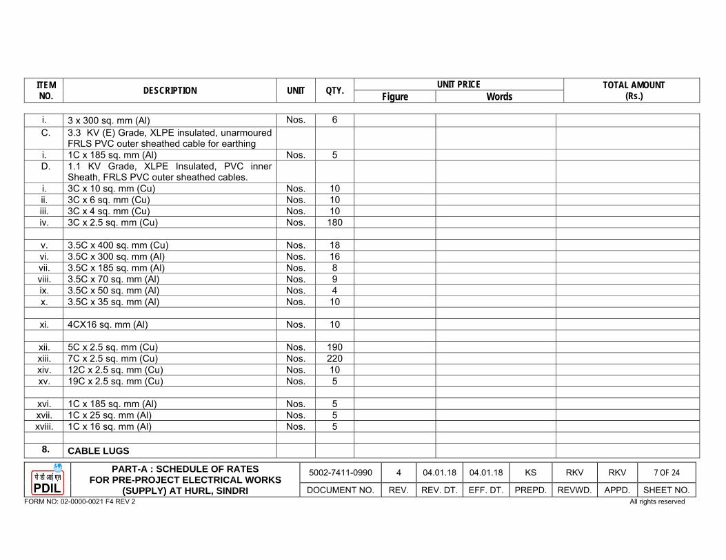
ITEM NO. DESCRIPTION UNIT QTY. UNIT PRICE TOTAL AMOUNT
(Rs.) Figure Words
PART-A : SCHEDULE OF RATES FOR PRE-PROJECT ELECTRICAL WORKS
(SUPPLY) AT HURL, SINDRI
5002-7411-0990 4 04.01.18 04.01.18 KS RKV RKV 7 OF 24
DOCUMENT NO. REV. REV. DT. EFF. DT. PREPD. REVWD. APPD. SHEET NO. FORM NO: 02-0000-0021 F4 REV 2 All rights reserved
i. 3 x 300 sq. mm (Al) Nos. 6 C. 3.3 KV (E) Grade, XLPE insulated, unarmoured
FRLS PVC outer sheathed cable for earthing
i. 1C x 185 sq. mm (Al) Nos. 5 D. 1.1 KV Grade, XLPE Insulated, PVC inner
Sheath, FRLS PVC outer sheathed cables.
i. 3C x 10 sq. mm (Cu) Nos. 10 ii. 3C x 6 sq. mm (Cu) Nos. 10 iii. 3C x 4 sq. mm (Cu) Nos. 10 iv. 3C x 2.5 sq. mm (Cu) Nos. 180
v. 3.5C x 400 sq. mm (Cu) Nos. 18 vi. 3.5C x 300 sq. mm (Al) Nos. 16 vii. 3.5C x 185 sq. mm (Al) Nos. 8 viii. 3.5C x 70 sq. mm (Al) Nos. 9 ix. 3.5C x 50 sq. mm (Al) Nos. 4 x. 3.5C x 35 sq. mm (Al) Nos. 10
xi. 4CX16 sq. mm (Al) Nos. 10
xii. 5C x 2.5 sq. mm (Cu) Nos. 190 xiii. 7C x 2.5 sq. mm (Cu) Nos. 220 xiv. 12C x 2.5 sq. mm (Cu) Nos. 10 xv. 19C x 2.5 sq. mm (Cu) Nos. 5
xvi. 1C x 185 sq. mm (Al) Nos. 5 xvii. 1C x 25 sq. mm (Al) Nos. 5 xviii. 1C x 16 sq. mm (Al) Nos. 5
8. CABLE LUGS
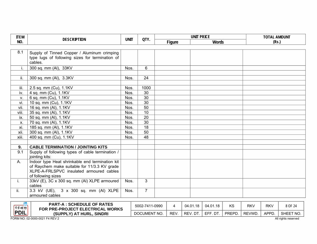
ITEM NO. DESCRIPTION UNIT QTY. UNIT PRICE TOTAL AMOUNT
(Rs.) Figure Words
PART-A : SCHEDULE OF RATES FOR PRE-PROJECT ELECTRICAL WORKS
(SUPPLY) AT HURL, SINDRI
5002-7411-0990 4 04.01.18 04.01.18 KS RKV RKV 8 OF 24
DOCUMENT NO. REV. REV. DT. EFF. DT. PREPD. REVWD. APPD. SHEET NO. FORM NO: 02-0000-0021 F4 REV 2 All rights reserved
8.1 Supply of Tinned Copper / Aluminum crimping type lugs of following sizes for termination of cables.
i. 300 sq. mm (Al), 33KV Nos. 6
ii. 300 sq. mm (Al), 3.3KV Nos. 24
iii. 2.5 sq. mm (Cu), 1.1KV Nos. 1000 iv. 4 sq. mm (Cu), 1.1KV Nos. 30 v. 6 sq. mm (Cu), 1.1KV Nos. 30 vi. 10 sq. mm (Cu), 1.1KV Nos. 30 vii. 16 sq. mm (Al), 1.1KV Nos. 50 viii. 35 sq. mm (Al), 1.1KV Nos. 10 ix. 50 sq. mm (Al), 1.1KV Nos. 20 x. 70 sq. mm (Al), 1.1KV Nos. 30 xi. 185 sq. mm (Al), 1.1KV Nos. 18 xii. 300 sq. mm (Al), 1.1KV Nos. 50 xiii. 400 sq. mm (Cu), 1.1KV Nos. 48 9. CABLE TERMINATION / JOINTING KITS 9.1 Supply of following types of cable termination /
jointing kits:
A. Indoor type Heat shrinkable end termination kit of Raychem make suitable for 11/3.3 KV grade XLPE-A-FRLSPVC insulated armoured cables of following sizes
i. 33kV (E), 3C x 300 sq. mm (Al) XLPE armoured cables
Nos. 3
ii. 3.3 kV (UE), 3 x 300 sq. mm (Al) XLPE armoured cables
Nos. 7

ITEM NO. DESCRIPTION UNIT QTY. UNIT PRICE TOTAL AMOUNT
(Rs.) Figure Words
PART-A : SCHEDULE OF RATES FOR PRE-PROJECT ELECTRICAL WORKS
(SUPPLY) AT HURL, SINDRI
5002-7411-0990 4 04.01.18 04.01.18 KS RKV RKV 9 OF 24
DOCUMENT NO. REV. REV. DT. EFF. DT. PREPD. REVWD. APPD. SHEET NO. FORM NO: 02-0000-0021 F4 REV 2 All rights reserved
B. Heat Shrinkable Raychem make straight through jointing kit suitable for 33/3.3/1.1 KV grade XLPE-A-FRLSPVC insulated armoured cables of following sizes
i. 3C x 300 sq. mm (Al, 33 KV) Nos. 2 ii. 3C x 300 sq. mm (Al, 3.3 KV) Nos. 2 iii. 3.5C x 400 sq. mm (Cu, 1.1KV) Nos. 2 iv. 3.5C x 300 sq. mm (Al, 1.1KV) Nos. 2 v. 3.5C x 185 sq. mm (Al, 1.1KV) Nos. 2 vi. 3.5C x 70 sq. mm (Al, 1.1KV) Nos. 2 vii. 3.5C x 50 sq. mm (Al, 1.1KV) Nos. 2 viii. 3.5C x 35 sq. mm (Al, 1.1KV) Nos. 2 ix. 4C x 16 sq. mm (Al, 1.1KV) Nos. 2 x. 3C x 2.5 sq. mm (Cu, 1.1KV) Nos. 2 xi. 5C x 2.5 sq. mm (Cu, 1.1KV) Nos. 2xii. 7C x 2.5 sq. mm (Cu, 1.1KV) Nos. 2 xiii. 12C x 2.5 sq. mm (Cu, 1.1KV) Nos. 2 xiv. 19C x 2.5 sq. mm (Cu, 1.1KV) Nos. 2
10. CABLE RACK (PREFABRICATED LADDER
TYPE GI CABLE TRAYS) & ACCESSORIES
10.1 Supply of GI ladder type Cable trays and their accessories i.e. supply of all hardware required i.e. J-hooks, GI Nut, Bolt, Washers, coupling plate etc. of following sizes and as per Technical Specification Doc. No. 5002-TS-0801 and drawing enclosed.
A. Straight Run Cable Trays i. 600mm wide Mtrs. 50 ii. 450mm wide Mtrs. 50
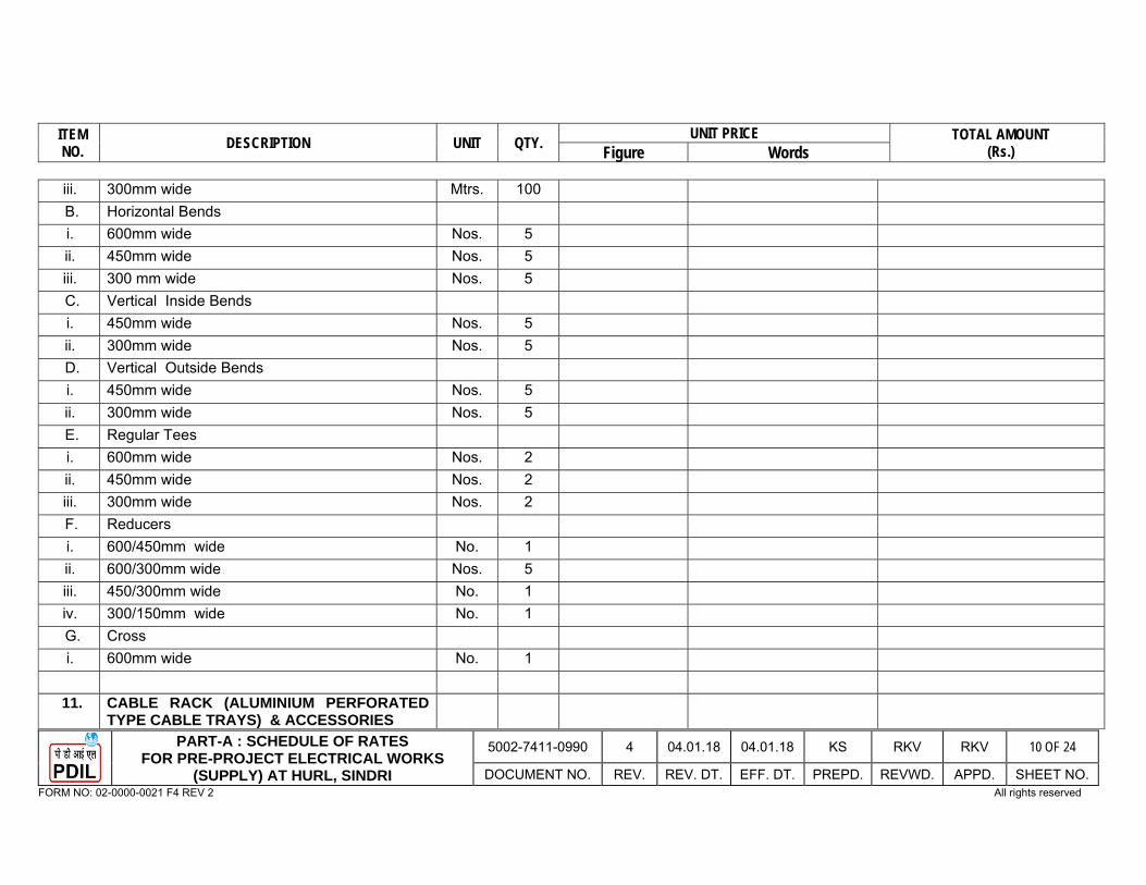
ITEM NO. DESCRIPTION UNIT QTY. UNIT PRICE TOTAL AMOUNT
(Rs.) Figure Words
PART-A : SCHEDULE OF RATES FOR PRE-PROJECT ELECTRICAL WORKS
(SUPPLY) AT HURL, SINDRI
5002-7411-0990 4 04.01.18 04.01.18 KS RKV RKV 10 OF 24
DOCUMENT NO. REV. REV. DT. EFF. DT. PREPD. REVWD. APPD. SHEET NO. FORM NO: 02-0000-0021 F4 REV 2 All rights reserved
iii. 300mm wide Mtrs. 100 B. Horizontal Bends i. 600mm wide Nos. 5 ii. 450mm wide Nos. 5 iii. 300 mm wide Nos. 5 C. Vertical Inside Bends i. 450mm wide Nos. 5 ii. 300mm wide Nos. 5 D. Vertical Outside Bends i. 450mm wide Nos. 5 ii. 300mm wide Nos. 5 E. Regular Tees i. 600mm wide Nos. 2 ii. 450mm wide Nos. 2 iii. 300mm wide Nos. 2 F. Reducers i. 600/450mm wide No. 1 ii. 600/300mm wide Nos. 5 iii. 450/300mm wide No. 1 iv. 300/150mm wide No. 1 G. Cross i. 600mm wide No. 1
11. CABLE RACK (ALUMINIUM PERFORATED TYPE CABLE TRAYS) & ACCESSORIES
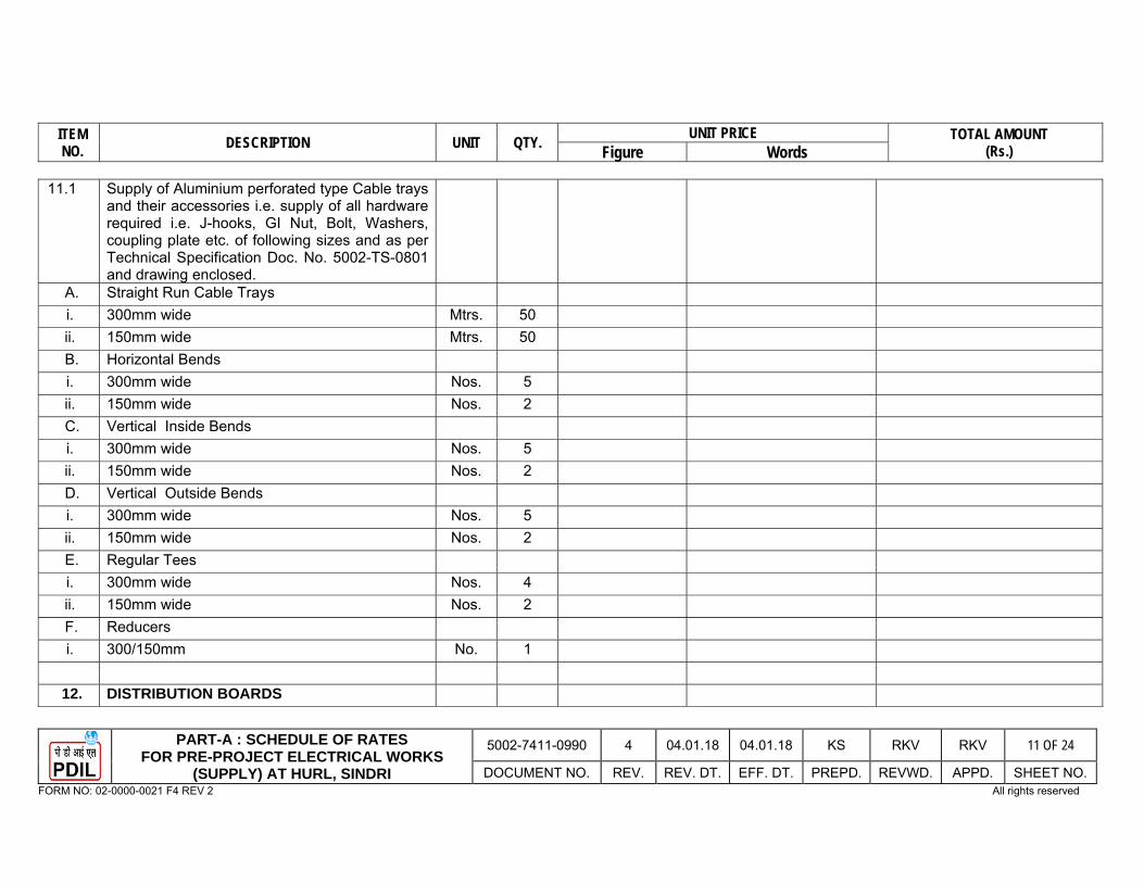
ITEM NO. DESCRIPTION UNIT QTY. UNIT PRICE TOTAL AMOUNT
(Rs.) Figure Words
PART-A : SCHEDULE OF RATES FOR PRE-PROJECT ELECTRICAL WORKS
(SUPPLY) AT HURL, SINDRI
5002-7411-0990 4 04.01.18 04.01.18 KS RKV RKV 11 OF 24
DOCUMENT NO. REV. REV. DT. EFF. DT. PREPD. REVWD. APPD. SHEET NO. FORM NO: 02-0000-0021 F4 REV 2 All rights reserved
11.1 Supply of Aluminium perforated type Cable trays and their accessories i.e. supply of all hardware required i.e. J-hooks, GI Nut, Bolt, Washers, coupling plate etc. of following sizes and as per Technical Specification Doc. No. 5002-TS-0801 and drawing enclosed.
A. Straight Run Cable Trays i. 300mm wide Mtrs. 50 ii. 150mm wide Mtrs. 50 B. Horizontal Bends i. 300mm wide Nos. 5 ii. 150mm wide Nos. 2 C. Vertical Inside Bends i. 300mm wide Nos. 5 ii. 150mm wide Nos. 2 D. Vertical Outside Bends i. 300mm wide Nos. 5 ii. 150mm wide Nos. 2 E. Regular Tees i. 300mm wide Nos. 4 ii. 150mm wide Nos. 2 F. Reducers i. 300/150mm No. 1
12. DISTRIBUTION BOARDS

ITEM NO. DESCRIPTION UNIT QTY. UNIT PRICE TOTAL AMOUNT
(Rs.) Figure Words
PART-A : SCHEDULE OF RATES FOR PRE-PROJECT ELECTRICAL WORKS
(SUPPLY) AT HURL, SINDRI
5002-7411-0990 4 04.01.18 04.01.18 KS RKV RKV 12 OF 24
DOCUMENT NO. REV. REV. DT. EFF. DT. PREPD. REVWD. APPD. SHEET NO. FORM NO: 02-0000-0021 F4 REV 2 All rights reserved
12.1 Supply of following Distribution Boards as specified in Technical Specification Doc. No. 5002-TS-0801.
i. 415 V, 3 Ph & N, floor mounted sheet steel enclosed Main Lighting Distribution Board (MLDB) as per Technical Specification 5002-TS-0801. It shall consist of 1 no. incoming 630 A MCCB incomer with Outdoor bus contactor (Photocell + Astro timer controlled) having 15 nos. 63 A TPN SFU as outgoing feeders and in indoor bus having 3 nos. 63A SFU as outgoing feeders.
No. 1
ii. 415 V, 3 Ph & N, wall mounted sheet steel enclosed Welding Socket Distribution Board as per Technical Specification 5002-TS-0801. It shall consist of 1 no. incoming 400 A 4P MCCB incomer with mechanical interlock & following nos. of outgoing feeders: 6 nos. 63 A 4P MCCB.
No. 1
iii. 415 V, 3 Ph & N, Feeder pillar box as specified in Technical Specification. It shall consist of 1 no. 63A TPN MCB incomer and 4 nos. 32A TPN MCCB outgoing feeders.
Nos. 6
12.2 Supply of 415 V Lighting sub Distribution Board / Single Phase Socket Distribution Board, as specified in Technical Specification 5002-TS-0801.
i. 415 V, 9-way wall / Steel Structure mounted Sheet steel enclosed Lighting Sub Distribution Board in IP55 degree of protection having 1 No. Incoming (63 A TP & Switched Neutral Isolator
Nos. 3
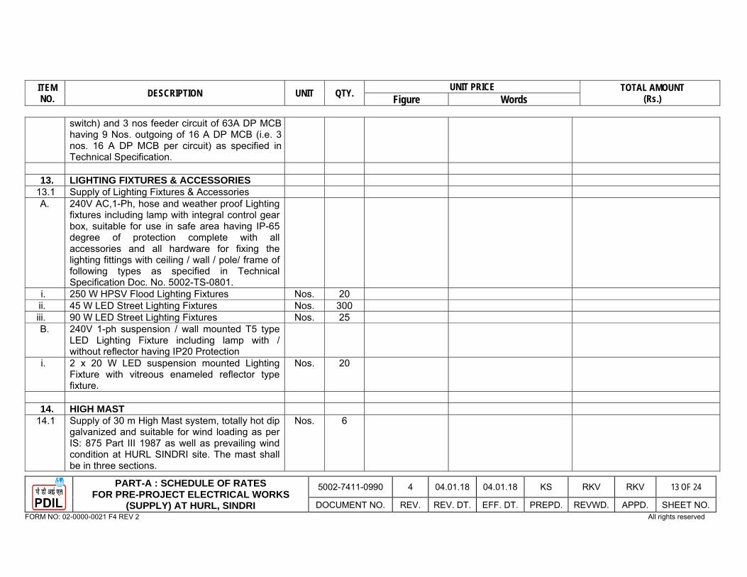
ITEM NO. DESCRIPTION UNIT QTY. UNIT PRICE TOTAL AMOUNT
(Rs.) Figure Words
PART-A : SCHEDULE OF RATES FOR PRE-PROJECT ELECTRICAL WORKS
(SUPPLY) AT HURL, SINDRI
5002-7411-0990 4 04.01.18 04.01.18 KS RKV RKV 13 OF 24
DOCUMENT NO. REV. REV. DT. EFF. DT. PREPD. REVWD. APPD. SHEET NO. FORM NO: 02-0000-0021 F4 REV 2 All rights reserved
switch) and 3 nos feeder circuit of 63A DP MCB having 9 Nos. outgoing of 16 A DP MCB (i.e. 3 nos. 16 A DP MCB per circuit) as specified in Technical Specification.
13. LIGHTING FIXTURES & ACCESSORIES
13.1 Supply of Lighting Fixtures & Accessories A. 240V AC,1-Ph, hose and weather proof Lighting
fixtures including lamp with integral control gear box, suitable for use in safe area having IP-65 degree of protection complete with all accessories and all hardware for fixing the lighting fittings with ceiling / wall / pole/ frame of following types as specified in Technical Specification Doc. No. 5002-TS-0801.
i. 250 W HPSV Flood Lighting Fixtures Nos. 20 ii. 45 W LED Street Lighting Fixtures Nos. 300 iii. 90 W LED Street Lighting Fixtures Nos. 25 B. 240V 1-ph suspension / wall mounted T5 type
LED Lighting Fixture including lamp with / without reflector having IP20 Protection
i. 2 x 20 W LED suspension mounted Lighting Fixture with vitreous enameled reflector type fixture.
Nos. 20
14. HIGH MAST
14.1 Supply of 30 m High Mast system, totally hot dip galvanized and suitable for wind loading as per IS: 875 Part III 1987 as well as prevailing wind condition at HURL SINDRI site. The mast shall be in three sections.
Nos. 6

ITEM NO. DESCRIPTION UNIT QTY. UNIT PRICE TOTAL AMOUNT
(Rs.) Figure Words
PART-A : SCHEDULE OF RATES FOR PRE-PROJECT ELECTRICAL WORKS
(SUPPLY) AT HURL, SINDRI
5002-7411-0990 4 04.01.18 04.01.18 KS RKV RKV 14 OF 24
DOCUMENT NO. REV. REV. DT. EFF. DT. PREPD. REVWD. APPD. SHEET NO. FORM NO: 02-0000-0021 F4 REV 2 All rights reserved
14.2 Accessories for 30 m high mast including head frame, stainless steel wire rope minimum 6 mm dia. (7/19 construction), double drum winch, with 2 nos. FLP plugs and socket combine. Galvanized lantern carriage arrangement suitable for 24 nos. luminaries symmetrically and its control gear boxes and its lighting accessories.
SET 6
14.3 Supply of specially designed non-integral flood light luminaries 9 nos. 2X400W, 3 Nos. 1X400W SON T lamps and its control gear boxes. Supply of aviation obstruction lights with neon spiral light source (1 no. fitting per mast is necessary)
SET 6
14.4 Supply of high powered three phase integral flameproof power tool for electrical operation of raising and lowering of lantern carriage with its FLP starter, FLP plug, FLP DOUBLE COMPRESSION ROLLED Aluminum cable glands & lugs suitable for 3.5Cx50 Sq. mm (Al) XLPE cable, supporting trolley, torque limiter and fixing chain.
SET 6
15. JUNCTION BOXES
15.1 Supply of 63A, 415V, 3Ph & N hose proof & weatherproof junction boxes in cast aluminium (LM-6) enclosure with IP–65 degree of protection and suitable for 2 Nos. 3.5x 50 Sq. mm (Al)cable & 1 nos. of 3Cx2.5 sq.mm(Cu) cable with terminal blocks of suitable size for easy termination of cables and as specified in
Nos. 300

ITEM NO. DESCRIPTION UNIT QTY. UNIT PRICE TOTAL AMOUNT
(Rs.) Figure Words
PART-A : SCHEDULE OF RATES FOR PRE-PROJECT ELECTRICAL WORKS
(SUPPLY) AT HURL, SINDRI
5002-7411-0990 4 04.01.18 04.01.18 KS RKV RKV 15 OF 24
DOCUMENT NO. REV. REV. DT. EFF. DT. PREPD. REVWD. APPD. SHEET NO. FORM NO: 02-0000-0021 F4 REV 2 All rights reserved
Technical specification Doc. No. 5002-TS-0801. 15.2 Supply of Junction Boxes in cast aluminium
(LM6) enclosure with IP–65 degree of protection and suitable for 3Cx2.5 sq.mm(Cu) cable with cable glands & terminal blocks of suitable size for easy termination of cables and as specified in Technical Specification Doc. No. 5002-TS-0801.
i. 25A, 230V, 1Ph & N 4 Way type hose proof & weatherproof
Nos. 30
16. PLANT LIGHTING POLES
16.1 Supply of hot dip galvanized MS tubular swaged lighting poles of following types suitable for base wind speed of 170 Km/Hr and along with suitable pole junction box.
i. 9M high ground mounted poles Nos. 25 ii. 5M high ground mounted poles Nos. 275
17. EARTHING & LIGHTNING MATERIAL
17.1 Supply of 3.8M, 100mm dia. heavy G.I. Pipe earth electrode having 100 micron zinc coating for earthing as per Technical Specifications 5002-TS-0801 complete with all accessories like earth bus, GI links for earth Pit connection etc. The hot dip galvanizing (minimum Zinc coating of 800 gms / sq. M as per IS-2629) shall be done after all fabrication. The electrodes shall be made from one piece length of pipe
Nos. 44
17.2 Supply of G.I. Earth Bus (50mm x 12mm x 390mm), with 10 nos. earthing holes and as per
Nos. 25
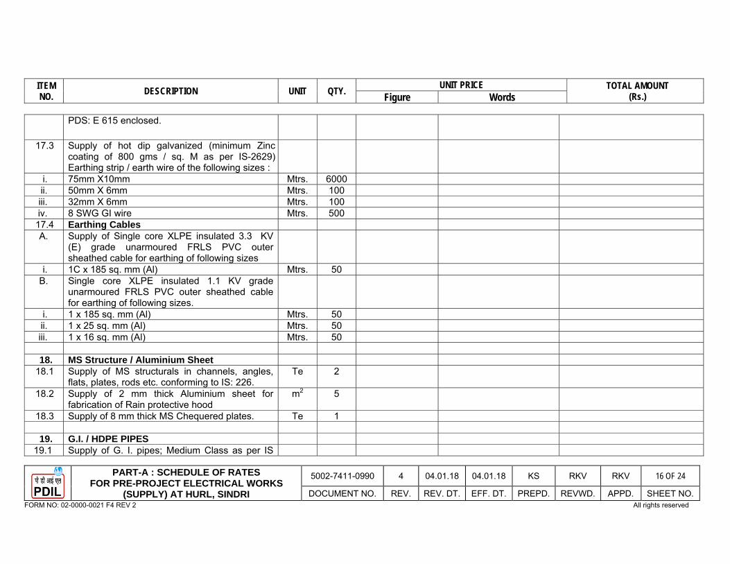
ITEM NO. DESCRIPTION UNIT QTY. UNIT PRICE TOTAL AMOUNT
(Rs.) Figure Words
PART-A : SCHEDULE OF RATES FOR PRE-PROJECT ELECTRICAL WORKS
(SUPPLY) AT HURL, SINDRI
5002-7411-0990 4 04.01.18 04.01.18 KS RKV RKV 16 OF 24
DOCUMENT NO. REV. REV. DT. EFF. DT. PREPD. REVWD. APPD. SHEET NO. FORM NO: 02-0000-0021 F4 REV 2 All rights reserved
PDS: E 615 enclosed.
17.3 Supply of hot dip galvanized (minimum Zinc coating of 800 gms / sq. M as per IS-2629) Earthing strip / earth wire of the following sizes :
i. 75mm X10mm Mtrs. 6000 ii. 50mm X 6mm Mtrs. 100 iii. 32mm X 6mm Mtrs. 100 iv. 8 SWG GI wire Mtrs. 500 17.4 Earthing Cables A. Supply of Single core XLPE insulated 3.3 KV
(E) grade unarmoured FRLS PVC outer sheathed cable for earthing of following sizes
i. 1C x 185 sq. mm (Al) Mtrs. 50 B. Single core XLPE insulated 1.1 KV grade
unarmoured FRLS PVC outer sheathed cable for earthing of following sizes.
i. 1 x 185 sq. mm (Al) Mtrs. 50 ii. 1 x 25 sq. mm (Al) Mtrs. 50 iii. 1 x 16 sq. mm (Al) Mtrs. 50
18. MS Structure / Aluminium Sheet
18.1 Supply of MS structurals in channels, angles, flats, plates, rods etc. conforming to IS: 226.
Te 2
18.2 Supply of 2 mm thick Aluminium sheet for fabrication of Rain protective hood
m2 5
18.3 Supply of 8 mm thick MS Chequered plates. Te 1
19. G.I. / HDPE PIPES 19.1 Supply of G. I. pipes; Medium Class as per IS
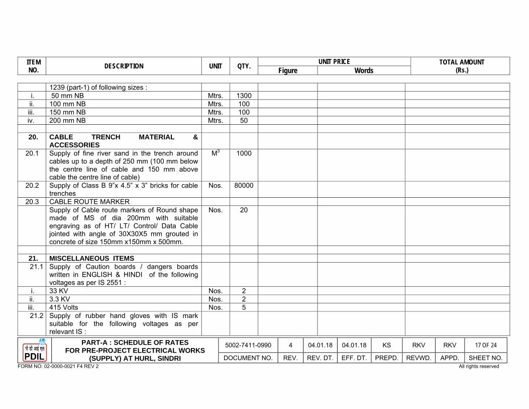
ITEM NO. DESCRIPTION UNIT QTY. UNIT PRICE TOTAL AMOUNT
(Rs.) Figure Words
PART-A : SCHEDULE OF RATES FOR PRE-PROJECT ELECTRICAL WORKS
(SUPPLY) AT HURL, SINDRI
5002-7411-0990 4 04.01.18 04.01.18 KS RKV RKV 17 OF 24
DOCUMENT NO. REV. REV. DT. EFF. DT. PREPD. REVWD. APPD. SHEET NO. FORM NO: 02-0000-0021 F4 REV 2 All rights reserved
1239 (part-1) of following sizes : i. 50 mm NB Mtrs. 1300ii. 100 mm NB Mtrs. 100 iii. 150 mm NB Mtrs. 100 iv. 200 mm NB Mtrs. 50
20. CABLE TRENCH MATERIAL &
ACCESSORIES
20.1 Supply of fine river sand in the trench around cables up to a depth of 250 mm (100 mm below the centre line of cable and 150 mm above cable the centre line of cable)
M3 1000
20.2 Supply of Class B 9”x 4.5” x 3” bricks for cable trenches
Nos. 80000
20.3 CABLE ROUTE MARKER Supply of Cable route markers of Round shape
made of MS of dia 200mm with suitable engraving as of HT/ LT/ Control/ Data Cable jointed with angle of 30X30X5 mm grouted in concrete of size 150mm x150mm x 500mm.
Nos. 20
21. MISCELLANEOUS ITEMS 21.1 Supply of Caution boards / dangers boards
written in ENGLISH & HINDI of the following voltages as per IS 2551 :
i. 33 KV Nos. 2 ii. 3.3 KV Nos. 2 iii. 415 Volts Nos. 5 21.2 Supply of rubber hand gloves with IS mark
suitable for the following voltages as per relevant IS :
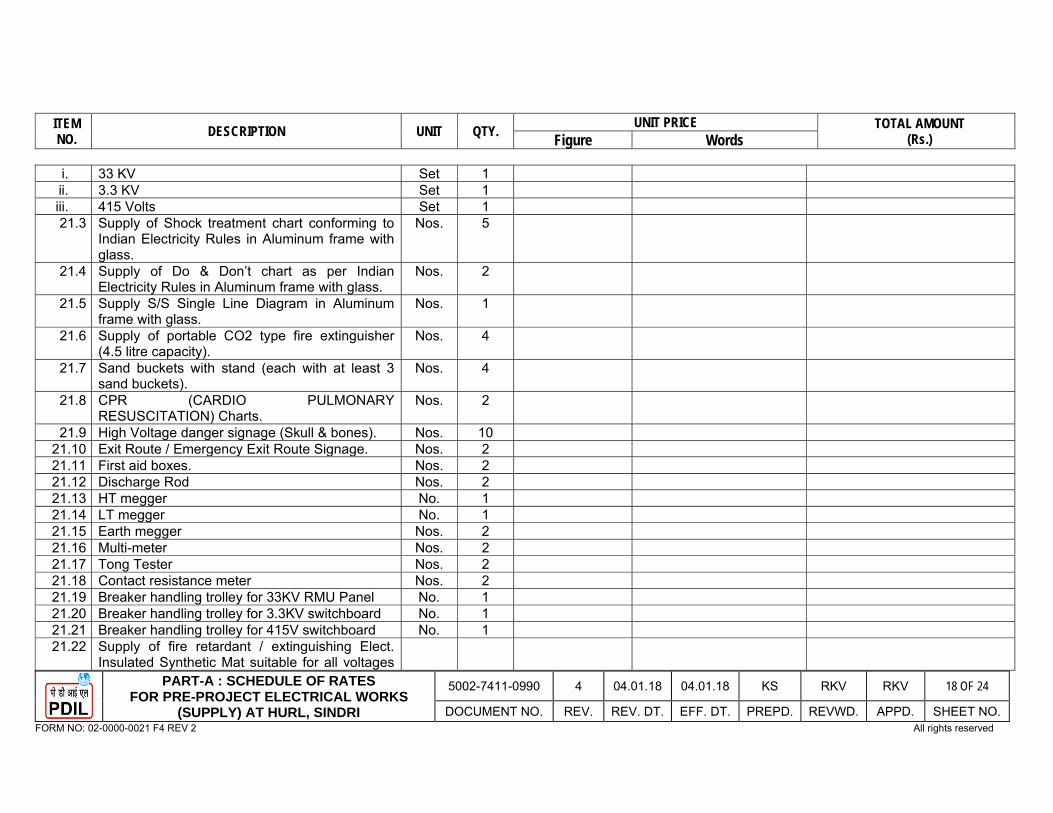
ITEM NO. DESCRIPTION UNIT QTY. UNIT PRICE TOTAL AMOUNT
(Rs.) Figure Words
PART-A : SCHEDULE OF RATES FOR PRE-PROJECT ELECTRICAL WORKS
(SUPPLY) AT HURL, SINDRI
5002-7411-0990 4 04.01.18 04.01.18 KS RKV RKV 18 OF 24
DOCUMENT NO. REV. REV. DT. EFF. DT. PREPD. REVWD. APPD. SHEET NO. FORM NO: 02-0000-0021 F4 REV 2 All rights reserved
i. 33 KV Set 1 ii. 3.3 KV Set 1iii. 415 Volts Set 1 21.3 Supply of Shock treatment chart conforming to
Indian Electricity Rules in Aluminum frame with glass.
Nos. 5
21.4 Supply of Do & Don’t chart as per Indian Electricity Rules in Aluminum frame with glass.
Nos. 2
21.5 Supply S/S Single Line Diagram in Aluminum frame with glass.
Nos. 1
21.6 Supply of portable CO2 type fire extinguisher (4.5 litre capacity).
Nos. 4
21.7 Sand buckets with stand (each with at least 3 sand buckets).
Nos. 4
21.8 CPR (CARDIO PULMONARY RESUSCITATION) Charts.
Nos. 2
21.9 High Voltage danger signage (Skull & bones). Nos. 1021.10 Exit Route / Emergency Exit Route Signage. Nos. 221.11 First aid boxes. Nos. 2 21.12 Discharge Rod Nos. 2 21.13 HT megger No. 1 21.14 LT megger No. 1 21.15 Earth megger Nos. 2 21.16 Multi-meter Nos. 2 21.17 Tong Tester Nos. 2 21.18 Contact resistance meter Nos. 2 21.19 Breaker handling trolley for 33KV RMU Panel No. 1 21.20 Breaker handling trolley for 3.3KV switchboard No. 1 21.21 Breaker handling trolley for 415V switchboard No. 1 21.22 Supply of fire retardant / extinguishing Elect.
Insulated Synthetic Mat suitable for all voltages
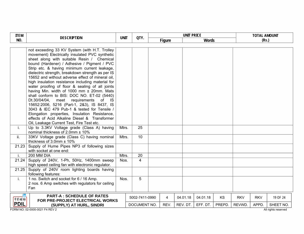
ITEM NO. DESCRIPTION UNIT QTY. UNIT PRICE TOTAL AMOUNT
(Rs.) Figure Words
PART-A : SCHEDULE OF RATES FOR PRE-PROJECT ELECTRICAL WORKS
(SUPPLY) AT HURL, SINDRI
5002-7411-0990 4 04.01.18 04.01.18 KS RKV RKV 19 OF 24
DOCUMENT NO. REV. REV. DT. EFF. DT. PREPD. REVWD. APPD. SHEET NO. FORM NO: 02-0000-0021 F4 REV 2 All rights reserved
not exceeding 33 KV System (with H.T. Trolley movement) Electrically insulated PVC synthetic sheet along with suitable Resin / Chemical bound (Hardener) / Adhesive / Pigment / PVC Strip etc. & having minimum current leakage, dielectric strength, breakdown strength as per IS 15652 and without adverse effect of mineral oil, high insulation resistance including material for water proofing of floor & sealing of all joints having Min. width of 1000 mm ± 20mm. Mats shall conform to BIS: DOC NO. ET-02 (5440) Dt.30/04/04, meet requirements of IS 15652:2006, 5216 (Part-1, 2&3), IS 8437, IS 3043 & IEC 479 Pub-1 & tested for Tensile / Elongation properties, Insulation Resistance, effects of Acid Alkaline Diesel & Transformer Oil, Leakage Current Test, Fire Test etc.
i. Up to 3.3KV Voltage grade (Class A) having nominal thickness of 2.0mm ± 10%
Mtrs. 25
ii. 33KV Voltage grade (Class C) having nominal thickness of 3.0mm ± 10%
Mtrs. 10
21.23 Supply of Hume Pipes NP3 of following sizes with socket at one end:
i. 200 MM DIA Mtrs. 20 21.24 Supply of 240V, 1-Ph, 50Hz, 1400mm sweep
high speed ceiling fan with electronic regulator. Nos. 4
21.25 Supply of 240V room lighting boards having following features:
i. 1 no. Switch and socket for 6 / 16 Amp. 2 nos. 6 Amp switches with regulators for ceiling Fan
Nos. 5
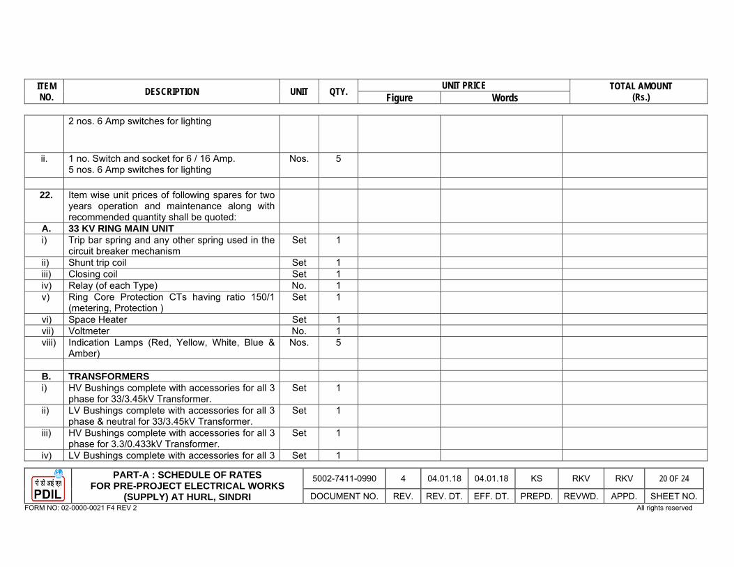
ITEM NO. DESCRIPTION UNIT QTY. UNIT PRICE TOTAL AMOUNT
(Rs.) Figure Words
PART-A : SCHEDULE OF RATES FOR PRE-PROJECT ELECTRICAL WORKS
(SUPPLY) AT HURL, SINDRI
5002-7411-0990 4 04.01.18 04.01.18 KS RKV RKV 20 OF 24
DOCUMENT NO. REV. REV. DT. EFF. DT. PREPD. REVWD. APPD. SHEET NO. FORM NO: 02-0000-0021 F4 REV 2 All rights reserved
2 nos. 6 Amp switches for lighting
ii. 1 no. Switch and socket for 6 / 16 Amp. 5 nos. 6 Amp switches for lighting
Nos. 5
22. Item wise unit prices of following spares for two
years operation and maintenance along with recommended quantity shall be quoted:
A. 33 KV RING MAIN UNIT i) Trip bar spring and any other spring used in the
circuit breaker mechanism Set 1
ii) Shunt trip coil Set 1 iii) Closing coil Set 1 iv) Relay (of each Type) No. 1 v) Ring Core Protection CTs having ratio 150/1
(metering, Protection ) Set 1
vi) Space Heater Set 1vii) Voltmeter No. 1 viii) Indication Lamps (Red, Yellow, White, Blue &
Amber) Nos. 5
B. TRANSFORMERS i) HV Bushings complete with accessories for all 3
phase for 33/3.45kV Transformer. Set 1
ii) LV Bushings complete with accessories for all 3 phase & neutral for 33/3.45kV Transformer.
Set 1
iii) HV Bushings complete with accessories for all 3 phase for 3.3/0.433kV Transformer.
Set 1
iv) LV Bushings complete with accessories for all 3 Set 1
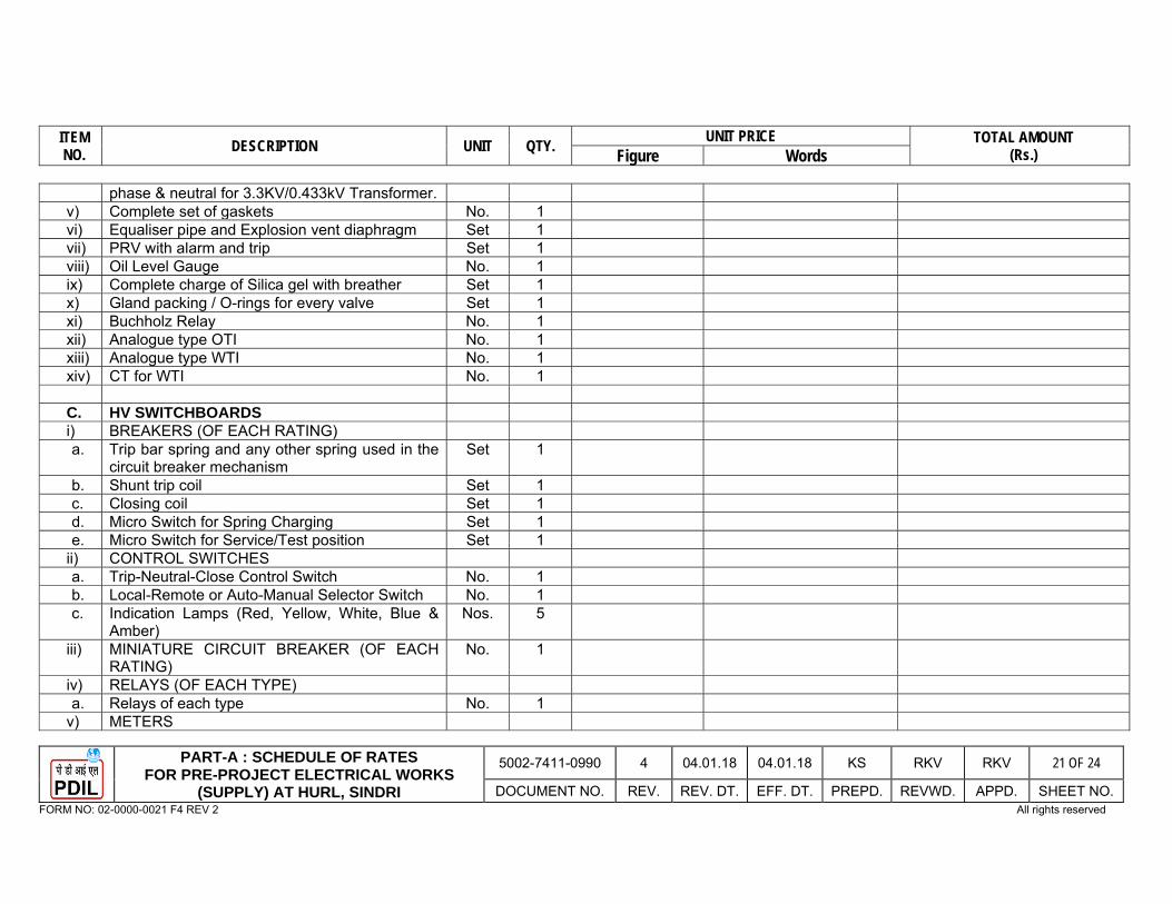
ITEM NO. DESCRIPTION UNIT QTY. UNIT PRICE TOTAL AMOUNT
(Rs.) Figure Words
PART-A : SCHEDULE OF RATES FOR PRE-PROJECT ELECTRICAL WORKS
(SUPPLY) AT HURL, SINDRI
5002-7411-0990 4 04.01.18 04.01.18 KS RKV RKV 21 OF 24
DOCUMENT NO. REV. REV. DT. EFF. DT. PREPD. REVWD. APPD. SHEET NO. FORM NO: 02-0000-0021 F4 REV 2 All rights reserved
phase & neutral for 3.3KV/0.433kV Transformer. v) Complete set of gaskets No. 1vi) Equaliser pipe and Explosion vent diaphragm Set 1 vii) PRV with alarm and trip Set 1 viii) Oil Level Gauge No. 1 ix) Complete charge of Silica gel with breather Set 1 x) Gland packing / O-rings for every valve Set 1 xi) Buchholz Relay No. 1 xii) Analogue type OTI No. 1 xiii) Analogue type WTI No. 1 xiv) CT for WTI No. 1
C. HV SWITCHBOARDS i) BREAKERS (OF EACH RATING) a. Trip bar spring and any other spring used in the
circuit breaker mechanism Set 1
b. Shunt trip coil Set 1c. Closing coil Set 1d. Micro Switch for Spring Charging Set 1 e. Micro Switch for Service/Test position Set 1
ii) CONTROL SWITCHES a. Trip-Neutral-Close Control Switch No. 1 b. Local-Remote or Auto-Manual Selector Switch No. 1 c. Indication Lamps (Red, Yellow, White, Blue &
Amber) Nos. 5
iii) MINIATURE CIRCUIT BREAKER (OF EACH RATING)
No. 1
iv) RELAYS (OF EACH TYPE) a. Relays of each type No. 1
v) METERS

ITEM NO. DESCRIPTION UNIT QTY. UNIT PRICE TOTAL AMOUNT
(Rs.) Figure Words
PART-A : SCHEDULE OF RATES FOR PRE-PROJECT ELECTRICAL WORKS
(SUPPLY) AT HURL, SINDRI
5002-7411-0990 4 04.01.18 04.01.18 KS RKV RKV 22 OF 24
DOCUMENT NO. REV. REV. DT. EFF. DT. PREPD. REVWD. APPD. SHEET NO. FORM NO: 02-0000-0021 F4 REV 2 All rights reserved
a. Ammeter of each type No. 1 b. Voltmeter No. 1c. KWh Meter No. 1
vi) FUSES (OF EACH RATING) a. Fuse link No. 1 b. Fuse fittings No. 1
vii) MISCELLANEOUS a. Surge Suppressor Nos. 3 b. Vacuum Bottle (3.3KV, 1250A) Nos. 3
D. LV SWITCHBOARDS i) BREAKERS (OF EACH RATING) a. Trip bar spring and any other spring used in the
circuit breaker mechanism Set 1
b. Cluster Contacts Set 1 c. Arc Chute Assembly Set 1 d. Shunt trip Coil Set 1e. Closing Coil Set 1f. Motors for MWS operated breakers No. 1 g. Secondary Isolating Contact Blocks Set 1 h. Shutter Assembly Set 1
ii) SWITCHES (OF EACH RATING) a. Trip-Neutral-Close Control Switch No. 1
iii) FUSES (OF EACH RATING) a. Fuse Link No. 1 b. Fuse Fittings No. 1
iv) CONTACTOR (OF EACH RATING) a. Contactor with Auxiliary Contacts Nos. 2 b. Operating Coil Nos. 2 c. Auxiliary Contact Block Nos. 2

ITEM NO. DESCRIPTION UNIT QTY. UNIT PRICE TOTAL AMOUNT
(Rs.) Figure Words
PART-A : SCHEDULE OF RATES FOR PRE-PROJECT ELECTRICAL WORKS
(SUPPLY) AT HURL, SINDRI
5002-7411-0990 4 04.01.18 04.01.18 KS RKV RKV 23 OF 24
DOCUMENT NO. REV. REV. DT. EFF. DT. PREPD. REVWD. APPD. SHEET NO. FORM NO: 02-0000-0021 F4 REV 2 All rights reserved
v) RELAYS a. Relays of each type No. 1b. Glass cover of each case No. 1
vi) MCB (OF EACH RATING) No. 1 vii) MISCELLANEOUS a. Power contactor (each type) No. 1 b. SFU (each type) No. 1
E. NEUTRAL EARTHING RESISTOR i. Bushing with accessories Set 1 ii. Support insulators Set 1 iii. Resistor element Set 1
F. INTERLOCKING SWITCH SOCKET & PLUG i. Switch of each rating Nos. 2 ii. Fuse base of each rating Nos. 2 iii. Fuse of each rating Nos. 2 iv. Plug Top Nos. 2
G. MLDB/LSDB/ACDB/DCDB i. 630A 4P MCCB No. 1 ii. Power Contactor for MLDB No. 1 iii. 400 A 4P MCCB No. 1 iv. 63 A TPN MCCB Nos. 2 v. 63 A TPN SFU Nos. 2 vi. 63 A DP SFU Nos. 4 vii. 32 A TPN MCB Nos. 2 viii. 32 A DP SFU Nos. 4 ix. 16 A DP MCB Nos. 4x. Terminal block for 63A Nos. 1
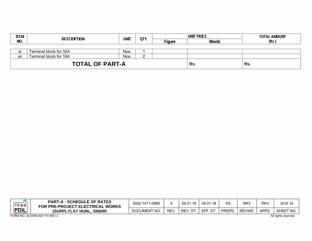
ITEM NO. DESCRIPTION UNIT QTY. UNIT PRICE TOTAL AMOUNT
(Rs.) Figure Words
PART-A : SCHEDULE OF RATES FOR PRE-PROJECT ELECTRICAL WORKS
(SUPPLY) AT HURL, SINDRI
5002-7411-0990 4 04.01.18 04.01.18 KS RKV RKV 24 OF 24
DOCUMENT NO. REV. REV. DT. EFF. DT. PREPD. REVWD. APPD. SHEET NO. FORM NO: 02-0000-0021 F4 REV 2 All rights reserved
xi. Terminal block for 32A Nos. 1 xii. Terminal block for 16A Nos. 2
TOTAL OF PART-A Rs. Rs.
SCHEDULE OF RATES FOR PRE-PROJECT ELECTRICAL WORKS
(ERECTION) AT HURL, SINDRI
5002-7411-0990 4 04.01.18 04.01.18 KS RKV RKV 1 OF 20
DOCUMENT NO. REV. REV. DT. EFF. DT. PREPD. REVWD. APPD. SHEET NO.FORM NO: 02-0000-0021 F4 REV 2 All rights reserved
PART-B
SCHEDULE OF RATES
FOR
PRE-PROJECT ELECTRICAL WORKS
(ERECTION)
AT
HURL, SINDRI

ITEM NO. DESCRIPTION UNIT QTY. UNIT PRICE TOTAL AMOUNT
(Rs.) FIGURE WORDS
SCHEDULE OF RATES FOR PRE-PROJECT ELECTRICAL WORKS
(ERECTION) AT HURL, SINDRI
5002-7411-0990 4 04.01.18 04.01.18 KS RKV RKV 2 OF 20
DOCUMENT NO. REV. REV. DT. EFF. DT. PREPD. REVWD. APPD. SHEET NO. FORM NO: 02-0000-0021 F4 REV 2 All rights reserved
GENERAL INSTRUCTIONS TO BIDDER: 1. The Schedule of Rates is to be read in conjunction with Technical Specification: Electrical Works (Supply & Erection) and other relevant sections / sub
sections.
2. The rates shall be applicable for all floors, heights and depths.
3. This being an item rate contract, the unit rate shall prevail, does any discrepancy arise between unit rate and total price, unit rate shall be considered for evaluation and arriving at the Contract Value.
4. Owner / Consultant reserves the right to interpolate or extrapolate the rate for any item, which is not covered in the Schedule of rates, from the rates available for similar item / work in the Schedule of Rates.
5. Whenever it is mentioned in the specifications that the bidder shall perform certain work or provide certain facilities / materials or certain item or activity is in bidder’s scope of services it is understood that the bidder shall do so at his cost within the item rates unless expressly stated otherwise.
6. Unit rates for erection shall inclusive of Unloading from Truck / Trailer, transportation from store (at site), handling, the cost of labour, supervision, all consumables, cost towards providing erection materials & hardware, necessary tools and tackles, and providing all the required facilities for execution and inspection, testing and commissioning, guarantees etc. Minor repair and touch painting work towards providing all required facilities for execution shall be in bidder’s scope.
7. Work shall involve, at every stage, correct identification of all equipment including loose equipment from stores, identifying spare items / excess items, listing the same and carefully storing them under the custody of the contractor. Information to this extent shall be passed on to the concerned Engineer-in-charge / owner. Certification of balance items after erection and return to the Engineer in-charge / Owner so assigned.
8. All equipment shall be deemed to have clear tags, descriptive letter writing indicating locations / sources (from - to), cable sizes, circuit no., unit no., and any other writing required to make installation completely informative. All costs in view of above shall be deemed to have been included in installation / commissioning.
9. All primary & secondary injection tests & testing of relays and other equipment as per relevant IS, code of practice for testing and commissioning shall be deemed to have been included for testing & commissioning. No extra charges shall be provided for that.
10. Wherever quantity is indicated as lot, estimated quantity shall be indicated by the Contractor.

ITEM NO. DESCRIPTION UNIT QTY. UNIT PRICE TOTAL AMOUNT
(Rs.) FIGURE WORDS
SCHEDULE OF RATES FOR PRE-PROJECT ELECTRICAL WORKS
(ERECTION) AT HURL, SINDRI
5002-7411-0990 4 04.01.18 04.01.18 KS RKV RKV 3 OF 20
DOCUMENT NO. REV. REV. DT. EFF. DT. PREPD. REVWD. APPD. SHEET NO. FORM NO: 02-0000-0021 F4 REV 2 All rights reserved
11. Any item specifically not indicated but considered necessary for completion of the job shall also be quoted by the Contractor under separate sheet. Work shall also include any other item of work required to complete the work in all respect as per the specifications, drawings and instructions of the Engineer-in-Charge whether specifically mentioned or not in the tender document.
12. This being a grass root job, the Contractor must visit HURL, Sindri sites to assess the quantum and nature of work before quoting. However, the Contractor shall inform PDIL / HURL, 1 week prior to their visit.
13. Man-days rate for skilled, semi-skilled, un-skilled labour and engineers shall also be indicated to cover any other work not specified herein, keeping Govt. circular on wages in consideration and in conformity with contract regulation and abolition act.
14. Quantities mentioned in the Schedule of Rates are indicative and not exhaustive in nature. Payment shall be made as per actual quantity used / certified at site by Engineer-in-charge.
15. Contractor shall indicate the prices of all electrical items as per attached documents. The quantities indicated in Schedule of Rates are estimated quantities and may change during detailed engineering as per site condition and prior approval from owner/consultant shall be required for the same. Quantity of some or all the items may increase or decrease up to any extent at the time of actual execution, however the total contract value shall be limited to total increase or decrease of 25% only. Contractor shall supply the equipments at the same rate as per these change quantities, irrespective of the changes in quantity of individual items.
16. Un-priced Price Schedule indicating quoted against each item shall be attached with bid documents for conformity that all the items have been quoted. Unit rate sought, for which quantities have not been indicated in the schedule of rates, shall also be quoted. However, the same shall not be considered for evaluation. Payment shall be made as per quantities executed.
17. Owner reserve their right to execute any additional works / extra works, during the execution of work, either by themselves or by appointing any other agency, even though such works are incidental to and necessary for the completion of works awarded to the Contractor. In the event of such decisions taken by Owner, Contractor is required to extend necessary cooperation, and act as per the instructions of Engineer-in-Charge.
18. Before procurement of any equipment / material, the Contractor shall submit drawing / document, Compliance Statement supported by Product Catalogue for review / approval. PDIL / HURL shall indicate the quantity of equipment / material to be procured during approval of respective equipment Document.
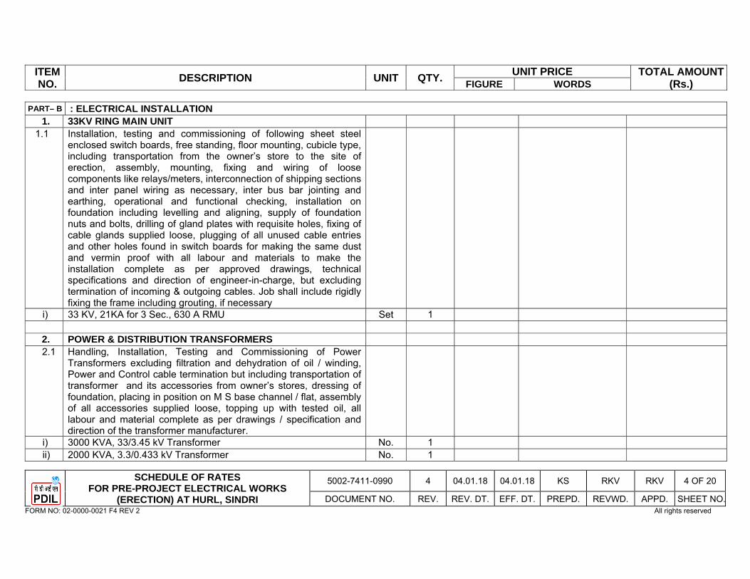
ITEM NO. DESCRIPTION UNIT QTY. UNIT PRICE TOTAL AMOUNT
(Rs.) FIGURE WORDS
SCHEDULE OF RATES FOR PRE-PROJECT ELECTRICAL WORKS
(ERECTION) AT HURL, SINDRI
5002-7411-0990 4 04.01.18 04.01.18 KS RKV RKV 4 OF 20
DOCUMENT NO. REV. REV. DT. EFF. DT. PREPD. REVWD. APPD. SHEET NO.FORM NO: 02-0000-0021 F4 REV 2 All rights reserved
PART– B : ELECTRICAL INSTALLATION 1. 33KV RING MAIN UNIT
1.1 Installation, testing and commissioning of following sheet steel enclosed switch boards, free standing, floor mounting, cubicle type, including transportation from the owner’s store to the site of erection, assembly, mounting, fixing and wiring of loose components like relays/meters, interconnection of shipping sections and inter panel wiring as necessary, inter bus bar jointing and earthing, operational and functional checking, installation on foundation including levelling and aligning, supply of foundation nuts and bolts, drilling of gland plates with requisite holes, fixing of cable glands supplied loose, plugging of all unused cable entries and other holes found in switch boards for making the same dust and vermin proof with all labour and materials to make the installation complete as per approved drawings, technical specifications and direction of engineer-in-charge, but excluding termination of incoming & outgoing cables. Job shall include rigidly fixing the frame including grouting, if necessary
i) 33 KV, 21KA for 3 Sec., 630 A RMU Set 1
2. POWER & DISTRIBUTION TRANSFORMERS 2.1 Handling, Installation, Testing and Commissioning of Power
Transformers excluding filtration and dehydration of oil / winding, Power and Control cable termination but including transportation of transformer and its accessories from owner’s stores, dressing of foundation, placing in position on M S base channel / flat, assembly of all accessories supplied loose, topping up with tested oil, all labour and material complete as per drawings / specification and direction of the transformer manufacturer.
i) 3000 KVA, 33/3.45 kV Transformer No. 1 ii) 2000 KVA, 3.3/0.433 kV Transformer No. 1
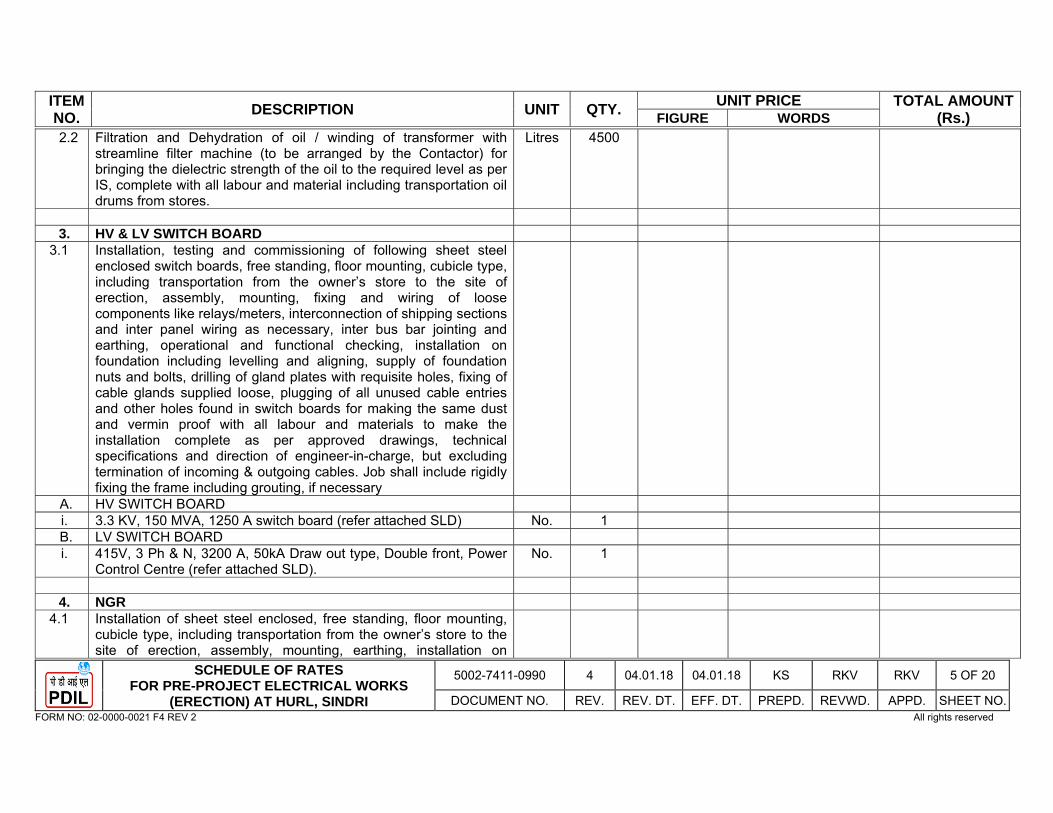
ITEM NO. DESCRIPTION UNIT QTY. UNIT PRICE TOTAL AMOUNT
(Rs.) FIGURE WORDS
SCHEDULE OF RATES FOR PRE-PROJECT ELECTRICAL WORKS
(ERECTION) AT HURL, SINDRI
5002-7411-0990 4 04.01.18 04.01.18 KS RKV RKV 5 OF 20
DOCUMENT NO. REV. REV. DT. EFF. DT. PREPD. REVWD. APPD. SHEET NO. FORM NO: 02-0000-0021 F4 REV 2 All rights reserved
2.2 Filtration and Dehydration of oil / winding of transformer with streamline filter machine (to be arranged by the Contactor) for bringing the dielectric strength of the oil to the required level as per IS, complete with all labour and material including transportation oil drums from stores.
Litres 4500
3. HV & LV SWITCH BOARD
3.1 Installation, testing and commissioning of following sheet steel enclosed switch boards, free standing, floor mounting, cubicle type, including transportation from the owner’s store to the site of erection, assembly, mounting, fixing and wiring of loose components like relays/meters, interconnection of shipping sections and inter panel wiring as necessary, inter bus bar jointing and earthing, operational and functional checking, installation on foundation including levelling and aligning, supply of foundation nuts and bolts, drilling of gland plates with requisite holes, fixing of cable glands supplied loose, plugging of all unused cable entries and other holes found in switch boards for making the same dust and vermin proof with all labour and materials to make the installation complete as per approved drawings, technical specifications and direction of engineer-in-charge, but excluding termination of incoming & outgoing cables. Job shall include rigidly fixing the frame including grouting, if necessary
A. HV SWITCH BOARD i. 3.3 KV, 150 MVA, 1250 A switch board (refer attached SLD) No. 1 B. LV SWITCH BOARD i. 415V, 3 Ph & N, 3200 A, 50kA Draw out type, Double front, Power
Control Centre (refer attached SLD). No. 1
4. NGR
4.1 Installation of sheet steel enclosed, free standing, floor mounting, cubicle type, including transportation from the owner’s store to the site of erection, assembly, mounting, earthing, installation on

ITEM NO. DESCRIPTION UNIT QTY. UNIT PRICE TOTAL AMOUNT
(Rs.) FIGURE WORDS
SCHEDULE OF RATES FOR PRE-PROJECT ELECTRICAL WORKS
(ERECTION) AT HURL, SINDRI
5002-7411-0990 4 04.01.18 04.01.18 KS RKV RKV 6 OF 20
DOCUMENT NO. REV. REV. DT. EFF. DT. PREPD. REVWD. APPD. SHEET NO. FORM NO: 02-0000-0021 F4 REV 2 All rights reserved
foundation including levelling and aligning, supply of foundation nuts and bolts, drilling of gland plates with requisite holes, fixing of cable glands supplied loose, plugging of all unused cable entries for making the same dust and vermin proof with all labour and materials to make the installation complete as per approved drawings, technical specifications and direction of engineer-in-charge, but excluding termination of cables. Job shall include rigidly fixing the frame including grouting, if necessary.
i. Neutral Grounding Resistors rated for 3.45/√3 KV ± 10%, 400A for 30 seconds, 4.98 ohms ± 10%, for 33/3.45 KV, 3 MVA Transformers.
No. 1
5. WEATHER PROOF / HOSE PROOF SWITCH SOCKET
5.1 Installation, testing and commissioning of interlocked type switch sockets with matching plugs complete with cable glands, lugs, terminal blocks etc. of following ratings:
i. 63A, 5-pin, 415V (Weather Proof) Nos. 10 ii. 25A, 3-pin, 240V (Weather Proof) Nos. 6
6. LAYING OF CABLES 6.1 Horizontal and vertical laying, testing (before and after laying) and
commissioning of following HV (33KV & 3.3KV) / LV Power & Control cables in readymade trenches, on pre-fabricated cable trays / racks, on already installed risers, support hangers, saddles etc. pulling through pipes on walls / columns, steel structures including transportation of cable drums from storage yard to the site, unrolling the drum, laying the required length of cables including supply and fixing of necessary saddles, saddle bars, cable tags, Al clamps for cables laid vertical on walls / columns / structures, risers with all labour, consumable materials and necessary hardware to make installation complete in all respect as per approved standard drawings and direction of engineer-in-charge.

ITEM NO. DESCRIPTION UNIT QTY. UNIT PRICE TOTAL AMOUNT
(Rs.) FIGURE WORDS
SCHEDULE OF RATES FOR PRE-PROJECT ELECTRICAL WORKS
(ERECTION) AT HURL, SINDRI
5002-7411-0990 4 04.01.18 04.01.18 KS RKV RKV 7 OF 20
DOCUMENT NO. REV. REV. DT. EFF. DT. PREPD. REVWD. APPD. SHEET NO. FORM NO: 02-0000-0021 F4 REV 2 All rights reserved
A. 33 KV (E) Grade, XLPE Insulated, PVC inner sheathed, Armoured, FRLS PVC outer sheathed cables.
i. 3C x 300 sq. mm (Al) Mtrs. 1500 B. 3.3 KV (UE) Grade, XLPE Insulated, PVC inner sheathed, FRLS
PVC outer sheathed cables.
i. 3C x 300 sq. mm (Al) Mtrs. 175 C. 1.1 KV Grade, XLPE Insulated, PVC inner Sheath, FRLS PVC
outer sheathed cables.
i. 3C x 10 sq. mm (Cu) Mtrs. 1000 ii. 3C x 6 sq. mm (Cu) Mtrs. 500 iii. 3C x 4 sq. mm (Cu) Mtrs. 500 iv. 3C x 2.5 sq. mm (Cu) Mtrs. 7200
v. 3.5C x 400 sq. mm (Cu) Mtrs. 250 vi. 3.5C x 300 sq. mm (Al) Mtrs. 5000 vii. 3.5C x 185 sq. mm (Al) Mtrs. 250 viii. 3.5C x 70 sq. mm (Al) Mtrs. 2000 ix. 3.5C x 50 sq. mm (Al) Mtrs. 4000 x. 3.5C x 35 sq. mm (Al) Mtrs. 3000 xi. 4CX16 sq. mm (Al) Mtrs. 7500 xii. 5C x 2.5 sq. mm (Cu) Mtrs. 2000 xiii. 7C x 2.5 sq. mm (Cu) Mtrs. 500 xiv. 12C x 2.5 sq. mm (Cu) Mtrs. 200 xv. 19C x 2.5 sq. mm (Cu) Mtrs. 200
D. Single core XLPE insulated 3.3 KV grade unarmoured FRLS PVC
outer sheathed cable for earthing
i. 1C x 185 sq. mm (Al) Mtrs. 50 E. Single core XLPE insulated 1.1 KV grade unarmoured FRLS PVC
outer sheathed cable for earthing.
i. 1 x 185 sq. mm (Al) Mtrs. 50

ITEM NO. DESCRIPTION UNIT QTY. UNIT PRICE TOTAL AMOUNT
(Rs.) FIGURE WORDS
SCHEDULE OF RATES FOR PRE-PROJECT ELECTRICAL WORKS
(ERECTION) AT HURL, SINDRI
5002-7411-0990 4 04.01.18 04.01.18 KS RKV RKV 8 OF 20
DOCUMENT NO. REV. REV. DT. EFF. DT. PREPD. REVWD. APPD. SHEET NO. FORM NO: 02-0000-0021 F4 REV 2 All rights reserved
ii. 1 x 25 sq. mm (Al) Mtrs. 50 iii. 1 x 16 sq. mm (Al) Mtrs. 50
7. TERMINATION OF CABLES 7.1 End termination and subsequent testing of XLPE/PVC insulated
single core / multi core armoured Cables of 33KV/3.3KV/1.1 KV grade, Al / Cu cable using suitable Heat Shrink Termination Kit, excluding supply of glands & lugs but including Glanding, all labour and consumable materials to make installation complete in all respect. The rate shall include drilling, taping of cable insulation, crimping of lugs to the conductor, connection of the lugs to equipment terminal, supply and fixing of G.I. nuts, screws, bolts, washers and other necessary hardware, PVC tape of required grade for taping, making cable entries dust and vermin proof, earthing etc. as per instruction of manufacturer, approved drawings, specifications and directions of engineer-in-charge.
A. 33 KV (E) Grade, XLPE Insulated, PVC inner sheathed, Armoured, FRLS PVC outer sheathed cables.
i. 3C x 300 sq. mm (Al) Nos. 2 B. 3.3 KV (UE) Grade, XLPE Insulated, PVC inner sheathed,
Armoured, FRLS PVC outer sheathed cables.
i. 3C x 300 sq. mm (Al) Nos. 6 C. 1.1 KV Grade, XLPE Insulated, PVC inner Sheath, FRLS PVC outer
sheathed cables.
i. 3C x 10 sq. mm (Cu) Nos. 10 ii. 3C x 6 sq. mm (Cu) Nos. 10 iii. 3C x 4 sq. mm (Cu) Nos. 10 iv. 3C x 2.5 sq. mm (Cu) Nos. 180
v. 3.5C x 400 sq. mm (Cu) Nos. 18 vi. 3.5C x 300 sq. mm (Al) Nos. 16 vii. 3.5C x 185 sq. mm (Al) Nos. 8
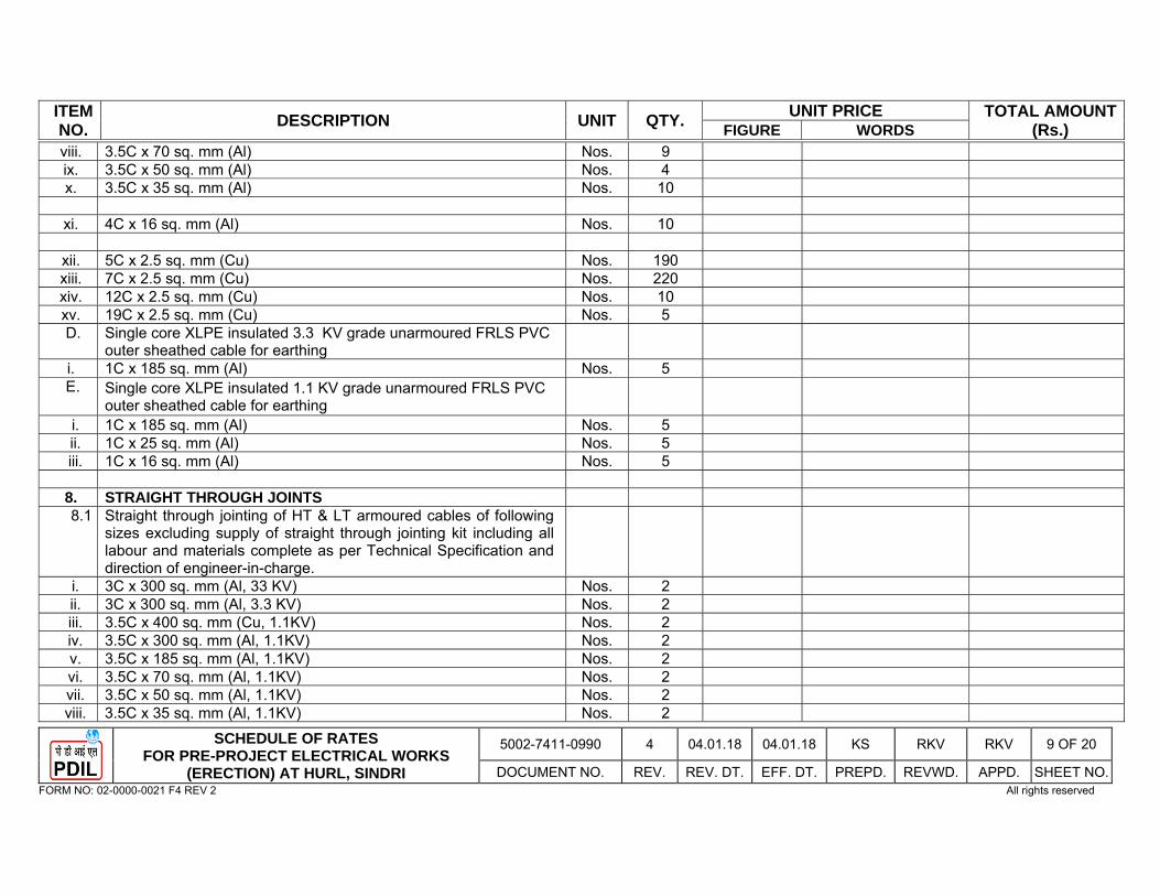
ITEM NO. DESCRIPTION UNIT QTY. UNIT PRICE TOTAL AMOUNT
(Rs.) FIGURE WORDS
SCHEDULE OF RATES FOR PRE-PROJECT ELECTRICAL WORKS
(ERECTION) AT HURL, SINDRI
5002-7411-0990 4 04.01.18 04.01.18 KS RKV RKV 9 OF 20
DOCUMENT NO. REV. REV. DT. EFF. DT. PREPD. REVWD. APPD. SHEET NO. FORM NO: 02-0000-0021 F4 REV 2 All rights reserved
viii. 3.5C x 70 sq. mm (Al) Nos. 9 ix. 3.5C x 50 sq. mm (Al) Nos. 4 x. 3.5C x 35 sq. mm (Al) Nos. 10
xi. 4C x 16 sq. mm (Al) Nos. 10
xii. 5C x 2.5 sq. mm (Cu) Nos. 190 xiii. 7C x 2.5 sq. mm (Cu) Nos. 220 xiv. 12C x 2.5 sq. mm (Cu) Nos. 10 xv. 19C x 2.5 sq. mm (Cu) Nos. 5 D. Single core XLPE insulated 3.3 KV grade unarmoured FRLS PVC
outer sheathed cable for earthing
i. 1C x 185 sq. mm (Al) Nos. 5 E. Single core XLPE insulated 1.1 KV grade unarmoured FRLS PVC
outer sheathed cable for earthing
i. 1C x 185 sq. mm (Al) Nos. 5ii. 1C x 25 sq. mm (Al) Nos. 5 iii. 1C x 16 sq. mm (Al) Nos. 5
8. STRAIGHT THROUGH JOINTS 8.1 Straight through jointing of HT & LT armoured cables of following
sizes excluding supply of straight through jointing kit including all labour and materials complete as per Technical Specification and direction of engineer-in-charge.
i. 3C x 300 sq. mm (Al, 33 KV) Nos. 2 ii. 3C x 300 sq. mm (Al, 3.3 KV) Nos. 2 iii. 3.5C x 400 sq. mm (Cu, 1.1KV) Nos. 2 iv. 3.5C x 300 sq. mm (Al, 1.1KV) Nos. 2 v. 3.5C x 185 sq. mm (Al, 1.1KV) Nos. 2vi. 3.5C x 70 sq. mm (Al, 1.1KV) Nos. 2 vii. 3.5C x 50 sq. mm (Al, 1.1KV) Nos. 2 viii. 3.5C x 35 sq. mm (Al, 1.1KV) Nos. 2

ITEM NO. DESCRIPTION UNIT QTY. UNIT PRICE TOTAL AMOUNT
(Rs.) FIGURE WORDS
SCHEDULE OF RATES FOR PRE-PROJECT ELECTRICAL WORKS
(ERECTION) AT HURL, SINDRI
5002-7411-0990 4 04.01.18 04.01.18 KS RKV RKV 10 OF 20
DOCUMENT NO. REV. REV. DT. EFF. DT. PREPD. REVWD. APPD. SHEET NO. FORM NO: 02-0000-0021 F4 REV 2 All rights reserved
ix. 4C x 16 sq. mm (Al, 1.1KV) Nos. 2 x. 3C x 2.5 sq. mm (Cu) Nos. 2 xi. 5C x 2.5 sq. mm (Cu) Nos. 2 xii. 7C x 2.5 sq. mm (Cu) Nos. 2 xiii. 12C x 2.5 sq. mm (Cu) Nos. 2 xiv. 19C x 2.5 sq. mm (Cu) Nos. 2
9. LAYING OF CABLE TRAYS 9.1 Installation, laying and connecting of pre-fabricated ladder type GI
cable trays and horizontal & vertical bends and regular Tees of different radii of various sizes on already erected supports or risers, including joining various cable trays by bolting with G.I. bolts, nuts & washers as per approved drawings (including fixing J-hooks, reducer coupler plate, adjustable coupler plate) as per the desired cable route and as per the drawings and directions of Engineer-in-charge. Job also includes supply of all hardware required i.e. J-hooks, GI Nut, Bolt, Washers etc.
A. Straight Run Cable Trays i. 600mm wide Mtrs. 50 ii. 450mm wide Mtrs. 50 iii. 300mm wide Mtrs. 100 B. Horizontal Bends i. 600mm wide Nos. 5 ii. 450mm wide Nos. 5 iii. 300 mm wide Nos. 5 C. Vertical Inside Bends i. ) 450mm wide Nos. 5 ii. ) 300mm wide Nos. 5 D. Vertical Outside Bends i. 450mm wide Nos. 5 ii. 300mm wide Nos. 5 E. Regular Tees

ITEM NO. DESCRIPTION UNIT QTY. UNIT PRICE TOTAL AMOUNT
(Rs.) FIGURE WORDS
SCHEDULE OF RATES FOR PRE-PROJECT ELECTRICAL WORKS
(ERECTION) AT HURL, SINDRI
5002-7411-0990 4 04.01.18 04.01.18 KS RKV RKV 11 OF 20
DOCUMENT NO. REV. REV. DT. EFF. DT. PREPD. REVWD. APPD. SHEET NO. FORM NO: 02-0000-0021 F4 REV 2 All rights reserved
i. 600mm wide Nos. 2 ii. 450mm wide Nos. 2 iii. 300mm wide Nos. 2 F. Reducers i. 600/450mm wide No. 1 ii. 600/300mm wide Nos. 5 iii. 450/300mm wide No. 1 iv. 300/150mm wide No. 1 G. Cross i. 600mm wide No. 19.2 Installation, laying and connecting of Al perforated type cable trays
and horizontal & vertical bends and regular Tees of different radii of various sizes on already erected supports or risers, including joining various cable trays by bolting with G.I. bolts, nuts & washers as per approved drawings (including fixing J-hooks, reducer coupler plate, adjustable coupler plate through supply of GI Nut Bolts, Washers etc) as per the desired cable route and as per the drawings and directions of Engineer-in-charge.
A. Straight Run Cable Trays i. 300mm wide Mtrs. 50 ii. 150mm wide Mtrs. 50 B. Horizontal Bends i. 300mm wide Nos. 5 ii. 150mm wide Nos. 2 C. Vertical Inside Bends i. 300mm wide Nos. 5ii. 150mm wide Nos. 2 D. Vertical Outside Bends i. 300mm wide Nos. 5 ii. 150mm wide Nos. 2 E. Regular Tees i. 300mm wide Nos. 4
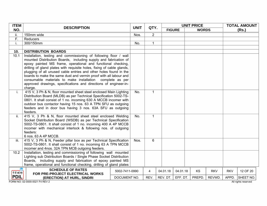
ITEM NO. DESCRIPTION UNIT QTY. UNIT PRICE TOTAL AMOUNT
(Rs.) FIGURE WORDS
SCHEDULE OF RATES FOR PRE-PROJECT ELECTRICAL WORKS
(ERECTION) AT HURL, SINDRI
5002-7411-0990 4 04.01.18 04.01.18 KS RKV RKV 12 OF 20
DOCUMENT NO. REV. REV. DT. EFF. DT. PREPD. REVWD. APPD. SHEET NO. FORM NO: 02-0000-0021 F4 REV 2 All rights reserved
ii. 150mm wide Nos. 2 F. Reducers i. 300/150mm No. 1
10. DISTRIBUTION BOARDS
10.1 Installation, testing and commissioning of following floor / wall mounted Distribution Boards, including supply and fabrication of epoxy painted MS frame, operational and functional checking, drilling of gland plates with requisite holes, fixing of cable glands, plugging of all unused cable entries and other holes found in the boards to make the same dust and vermin proof with all labour and consumable materials to make installation complete as per approved drawings, specifications and directions of engineer-in-charge.
i. 415 V, 3 Ph & N, floor mounted sheet steel enclosed Main Lighting Distribution Board (MLDB) as per Technical Specification 5002-TS-0801. It shall consist of 1 no. incoming 630 A MCCB incomer with outdoor bus contactor having 15 nos. 63 A TPN SFU as outgoing feeders and in door bus having 3 nos. 63A SFU as outgoing feeders.
No. 1
ii. 415 V, 3 Ph & N, floor mounted sheet steel enclosed Welding Socket Distribution Board (WSDB) as per Technical Specification 5002-TS-0801. It shall consist of 1 no. incoming 400 A 4P MCCB incomer with mechanical interlock & following nos. of outgoing feeders: 6 nos. 63 A 4P MCCB.
No. 1
iii. 415 V, 3 Ph & N, Feeder pillar box as per Technical Specification 5002-TS-0801. It shall consist of 1 no. incoming 63 A TPN MCCB incomer and 4nos. 32A TPN MCB outgoing feeders.
Nos. 6
10.2 Installation, testing and commissioning of following wall mounted Lighting sub Distribution Boards / Single Phase Socket Distribution Boards, including supply and fabrication of epoxy painted MS frame, operational and functional checking, drilling of gland plates
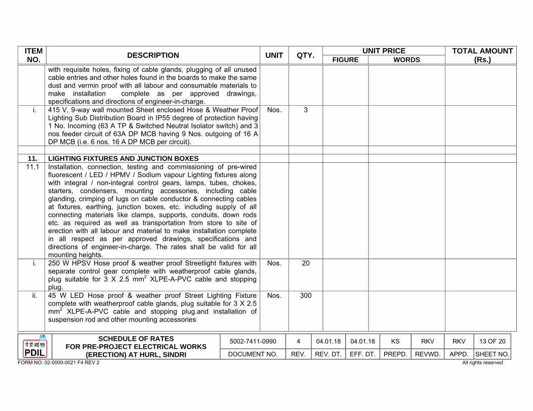
ITEM NO. DESCRIPTION UNIT QTY. UNIT PRICE TOTAL AMOUNT
(Rs.) FIGURE WORDS
SCHEDULE OF RATES FOR PRE-PROJECT ELECTRICAL WORKS
(ERECTION) AT HURL, SINDRI
5002-7411-0990 4 04.01.18 04.01.18 KS RKV RKV 13 OF 20
DOCUMENT NO. REV. REV. DT. EFF. DT. PREPD. REVWD. APPD. SHEET NO. FORM NO: 02-0000-0021 F4 REV 2 All rights reserved
with requisite holes, fixing of cable glands, plugging of all unused cable entries and other holes found in the boards to make the same dust and vermin proof with all labour and consumable materials to make installation complete as per approved drawings, specifications and directions of engineer-in-charge.
i.
415 V, 9-way wall mounted Sheet enclosed Hose & Weather Proof Lighting Sub Distribution Board in IP55 degree of protection having 1 No. Incoming (63 A TP & Switched Neutral Isolator switch) and 3 nos feeder circuit of 63A DP MCB having 9 Nos. outgoing of 16 A DP MCB (i.e. 6 nos. 16 A DP MCB per circuit).
Nos. 3
11. LIGHTING FIXTURES AND JUNCTION BOXES
11.1 Installation, connection, testing and commissioning of pre-wired fluorescent / LED / HPMV / Sodium vapour Lighting fixtures along with integral / non-integral control gears, lamps, tubes, chokes, starters, condensers, mounting accessories, including cable glanding, crimping of lugs on cable conductor & connecting cables at fixtures, earthing, junction boxes, etc. including supply of all connecting materials like clamps, supports, conduits, down rods etc. as required as well as transportation from store to site of erection with all labour and material to make installation complete in all respect as per approved drawings, specifications and directions of engineer-in-charge. The rates shall be valid for all mounting heights.
i. 250 W HPSV Hose proof & weather proof Streetlight fixtures with separate control gear complete with weatherproof cable glands, plug suitable for 3 X 2.5 mm2 XLPE-A-PVC cable and stopping plug.
Nos. 20
ii. 45 W LED Hose proof & weather proof Street Lighting Fixture complete with weatherproof cable glands, plug suitable for 3 X 2.5 mm2 XLPE-A-PVC cable and stopping plug.and installation of suspension rod and other mounting accessories
Nos. 300
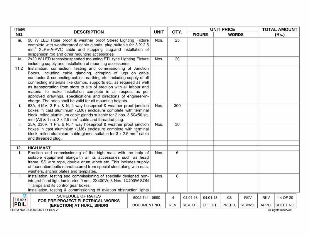
ITEM NO. DESCRIPTION UNIT QTY. UNIT PRICE TOTAL AMOUNT
(Rs.) FIGURE WORDS
SCHEDULE OF RATES FOR PRE-PROJECT ELECTRICAL WORKS
(ERECTION) AT HURL, SINDRI
5002-7411-0990 4 04.01.18 04.01.18 KS RKV RKV 14 OF 20
DOCUMENT NO. REV. REV. DT. EFF. DT. PREPD. REVWD. APPD. SHEET NO. FORM NO: 02-0000-0021 F4 REV 2 All rights reserved
iii. 90 W LED Hose proof & weather proof Street Lighting Fixture complete with weatherproof cable glands, plug suitable for 3 X 2.5 mm2 XLPE-A-PVC cable and stopping plug.and installation of suspension rod and other mounting accessories
Nos. 25
iv. 2x20 W LED recess/suspended mounting FTL type Lighting Fixture including supply and installation of mounting accessories.
Nos. 20
11.2 Installation, connection, testing and commissioning of Junction Boxes, including cable glanding, crimping of lugs on cable conductor & connecting cables, earthing etc. including supply of all connecting materials like clamps, supports etc. as required as well as transportation from store to site of erection with all labour and material to make installation complete in all respect as per approved drawings, specifications and directions of engineer-in-charge. The rates shall be valid for all mounting heights.
i. 63A, 415V, 3 Ph. & N, 4 way hoseproof & weather proof junction boxes in cast aluminium (LM6) enclosure complete with terminal block, rolled aluminium cable glands suitable for 2 nos. 3.5Cx50 sq. mm (Al) & 1 no. 3 x 2.5 mm2 cable and threaded plug.
Nos. 300
ii. 25A, 230V, 1 Ph. & N, 4 way hoseproof & weather proof junction boxes in cast aluminium (LM6) enclosure complete with terminal block, rolled aluminium cable glands suitable for 3 x 2.5 mm2 cable and threaded plug.
Nos. 30
12. HIGH MAST
i. Erection and commissioning of the high mast with the help of suitable equipment alongwith all its accessories such as head frame, SS wire rope, double drum winch etc. This includes supply of foundation bolts manufactured from special steel along with nuts, washers, anchor plates and templates.
Nos. 6
ii. Installation, testing and commissioning of specially designed non-integral flood light luminaries 9 nos. 2X400W, 3 Nos. 1X400W SON T lamps and its control gear boxes. Installation, testing & commissioning of aviation obstruction lights
Nos. 6
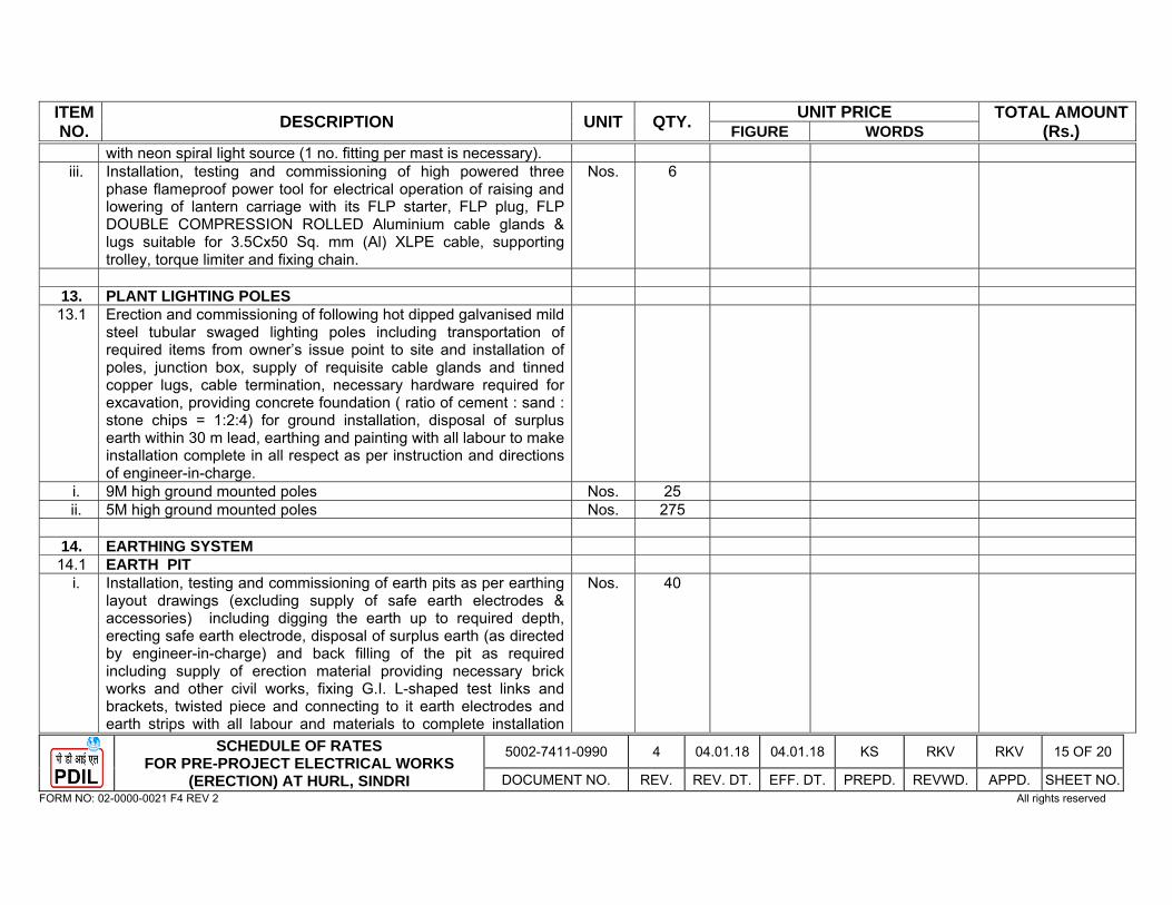
ITEM NO. DESCRIPTION UNIT QTY. UNIT PRICE TOTAL AMOUNT
(Rs.) FIGURE WORDS
SCHEDULE OF RATES FOR PRE-PROJECT ELECTRICAL WORKS
(ERECTION) AT HURL, SINDRI
5002-7411-0990 4 04.01.18 04.01.18 KS RKV RKV 15 OF 20
DOCUMENT NO. REV. REV. DT. EFF. DT. PREPD. REVWD. APPD. SHEET NO. FORM NO: 02-0000-0021 F4 REV 2 All rights reserved
with neon spiral light source (1 no. fitting per mast is necessary). iii. Installation, testing and commissioning of high powered three
phase flameproof power tool for electrical operation of raising and lowering of lantern carriage with its FLP starter, FLP plug, FLP DOUBLE COMPRESSION ROLLED Aluminium cable glands & lugs suitable for 3.5Cx50 Sq. mm (Al) XLPE cable, supporting trolley, torque limiter and fixing chain.
Nos. 6
13. PLANT LIGHTING POLES
13.1 Erection and commissioning of following hot dipped galvanised mild steel tubular swaged lighting poles including transportation of required items from owner’s issue point to site and installation of poles, junction box, supply of requisite cable glands and tinned copper lugs, cable termination, necessary hardware required for excavation, providing concrete foundation ( ratio of cement : sand : stone chips = 1:2:4) for ground installation, disposal of surplus earth within 30 m lead, earthing and painting with all labour to make installation complete in all respect as per instruction and directions of engineer-in-charge.
i. 9M high ground mounted poles Nos. 25 ii. 5M high ground mounted poles Nos. 275
14. EARTHING SYSTEM 14.1 EARTH PIT
i. Installation, testing and commissioning of earth pits as per earthing layout drawings (excluding supply of safe earth electrodes & accessories) including digging the earth up to required depth, erecting safe earth electrode, disposal of surplus earth (as directed by engineer-in-charge) and back filling of the pit as required including supply of erection material providing necessary brick works and other civil works, fixing G.I. L-shaped test links and brackets, twisted piece and connecting to it earth electrodes and earth strips with all labour and materials to complete installation
Nos. 40
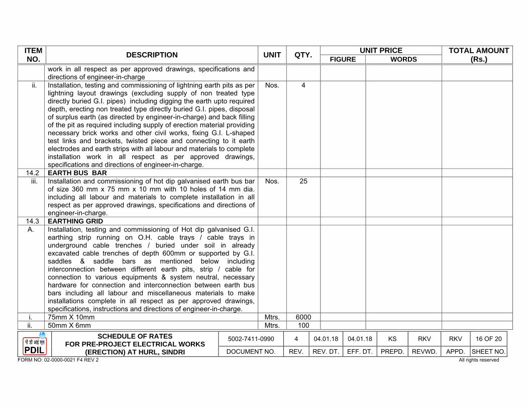
ITEM NO. DESCRIPTION UNIT QTY. UNIT PRICE TOTAL AMOUNT
(Rs.) FIGURE WORDS
SCHEDULE OF RATES FOR PRE-PROJECT ELECTRICAL WORKS
(ERECTION) AT HURL, SINDRI
5002-7411-0990 4 04.01.18 04.01.18 KS RKV RKV 16 OF 20
DOCUMENT NO. REV. REV. DT. EFF. DT. PREPD. REVWD. APPD. SHEET NO. FORM NO: 02-0000-0021 F4 REV 2 All rights reserved
work in all respect as per approved drawings, specifications and directions of engineer-in-charge
ii. Installation, testing and commissioning of lightning earth pits as per lightning layout drawings (excluding supply of non treated type directly buried G.I. pipes) including digging the earth upto required depth, erecting non treated type directly buried G.I. pipes, disposal of surplus earth (as directed by engineer-in-charge) and back filling of the pit as required including supply of erection material providing necessary brick works and other civil works, fixing G.I. L-shaped test links and brackets, twisted piece and connecting to it earth electrodes and earth strips with all labour and materials to complete installation work in all respect as per approved drawings, specifications and directions of engineer-in-charge.
Nos. 4
14.2 EARTH BUS BAR iii. Installation and commissioning of hot dip galvanised earth bus bar
of size 360 mm x 75 mm x 10 mm with 10 holes of 14 mm dia. including all labour and materials to complete installation in all respect as per approved drawings, specifications and directions of engineer-in-charge.
Nos. 25
14.3 EARTHING GRID A. Installation, testing and commissioning of Hot dip galvanised G.I.
earthing strip running on O.H. cable trays / cable trays in underground cable trenches / buried under soil in already excavated cable trenches of depth 600mm or supported by G.I. saddles & saddle bars as mentioned below including interconnection between different earth pits, strip / cable for connection to various equipments & system neutral, necessary hardware for connection and interconnection between earth bus bars including all labour and miscellaneous materials to make installations complete in all respect as per approved drawings, specifications, instructions and directions of engineer-in-charge.
i. 75mm X 10mm Mtrs. 6000 ii. 50mm X 6mm Mtrs. 100
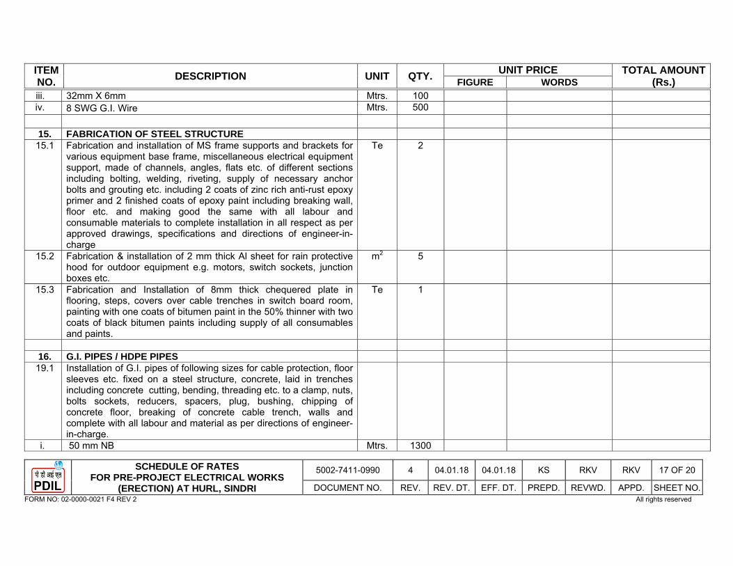
ITEM NO. DESCRIPTION UNIT QTY. UNIT PRICE TOTAL AMOUNT
(Rs.) FIGURE WORDS
SCHEDULE OF RATES FOR PRE-PROJECT ELECTRICAL WORKS
(ERECTION) AT HURL, SINDRI
5002-7411-0990 4 04.01.18 04.01.18 KS RKV RKV 17 OF 20
DOCUMENT NO. REV. REV. DT. EFF. DT. PREPD. REVWD. APPD. SHEET NO. FORM NO: 02-0000-0021 F4 REV 2 All rights reserved
iii. 32mm X 6mm Mtrs. 100 iv. 8 SWG G.I. Wire Mtrs. 500
15. FABRICATION OF STEEL STRUCTURE
15.1 Fabrication and installation of MS frame supports and brackets for various equipment base frame, miscellaneous electrical equipment support, made of channels, angles, flats etc. of different sections including bolting, welding, riveting, supply of necessary anchor bolts and grouting etc. including 2 coats of zinc rich anti-rust epoxy primer and 2 finished coats of epoxy paint including breaking wall, floor etc. and making good the same with all labour and consumable materials to complete installation in all respect as per approved drawings, specifications and directions of engineer-in-charge
Te 2
15.2 Fabrication & installation of 2 mm thick Al sheet for rain protective hood for outdoor equipment e.g. motors, switch sockets, junction boxes etc.
m2 5
15.3 Fabrication and Installation of 8mm thick chequered plate in flooring, steps, covers over cable trenches in switch board room, painting with one coats of bitumen paint in the 50% thinner with two coats of black bitumen paints including supply of all consumables and paints.
Te 1
16. G.I. PIPES / HDPE PIPES
19.1 Installation of G.I. pipes of following sizes for cable protection, floor sleeves etc. fixed on a steel structure, concrete, laid in trenches including concrete cutting, bending, threading etc. to a clamp, nuts, bolts sockets, reducers, spacers, plug, bushing, chipping of concrete floor, breaking of concrete cable trench, walls and complete with all labour and material as per directions of engineer-in-charge.
i. 50 mm NB Mtrs. 1300
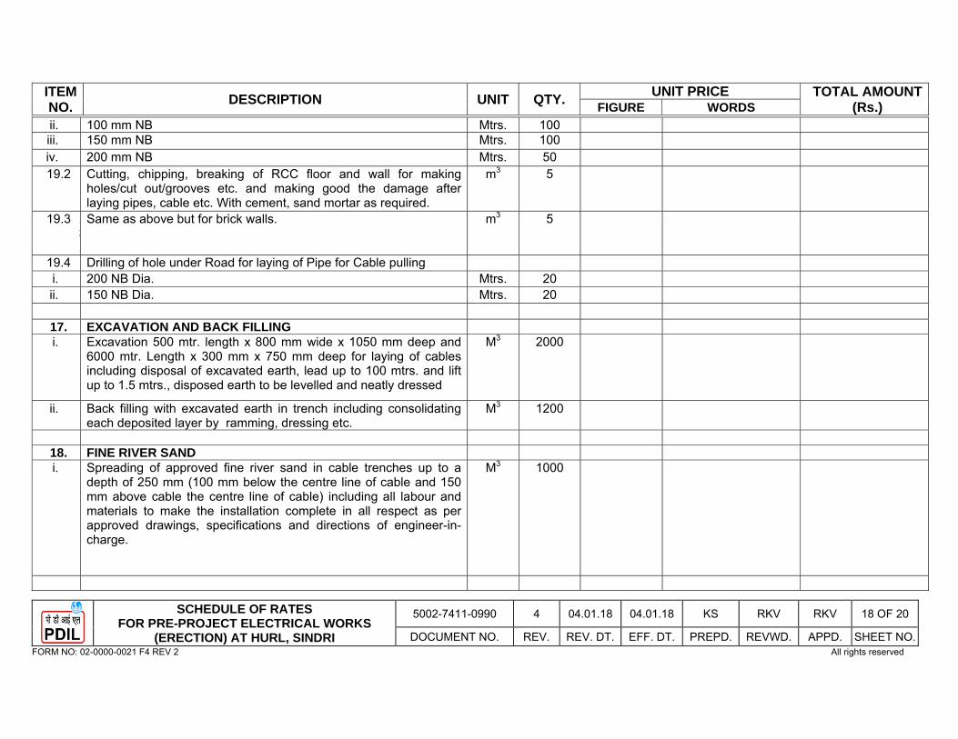
ITEM NO. DESCRIPTION UNIT QTY. UNIT PRICE TOTAL AMOUNT
(Rs.) FIGURE WORDS
SCHEDULE OF RATES FOR PRE-PROJECT ELECTRICAL WORKS
(ERECTION) AT HURL, SINDRI
5002-7411-0990 4 04.01.18 04.01.18 KS RKV RKV 18 OF 20
DOCUMENT NO. REV. REV. DT. EFF. DT. PREPD. REVWD. APPD. SHEET NO. FORM NO: 02-0000-0021 F4 REV 2 All rights reserved
ii. 100 mm NB Mtrs. 100 iii. 150 mm NB Mtrs. 100 iv. 200 mm NB Mtrs. 50 19.2 Cutting, chipping, breaking of RCC floor and wall for making
holes/cut out/grooves etc. and making good the damage after laying pipes, cable etc. With cement, sand mortar as required.
m3 5
19.3 13.
Same as above but for brick walls. m3 5
19.4 Drilling of hole under Road for laying of Pipe for Cable pulling i. 200 NB Dia. Mtrs. 20 ii. 150 NB Dia. Mtrs. 20
17. EXCAVATION AND BACK FILLING i. Excavation 500 mtr. length x 800 mm wide x 1050 mm deep and
6000 mtr. Length x 300 mm x 750 mm deep for laying of cables including disposal of excavated earth, lead up to 100 mtrs. and lift up to 1.5 mtrs., disposed earth to be levelled and neatly dressed
M3 2000
ii. Back filling with excavated earth in trench including consolidating each deposited layer by ramming, dressing etc.
M3 1200
18. FINE RIVER SAND i. Spreading of approved fine river sand in cable trenches up to a
depth of 250 mm (100 mm below the centre line of cable and 150 mm above cable the centre line of cable) including all labour and materials to make the installation complete in all respect as per approved drawings, specifications and directions of engineer-in-charge.
M3 1000
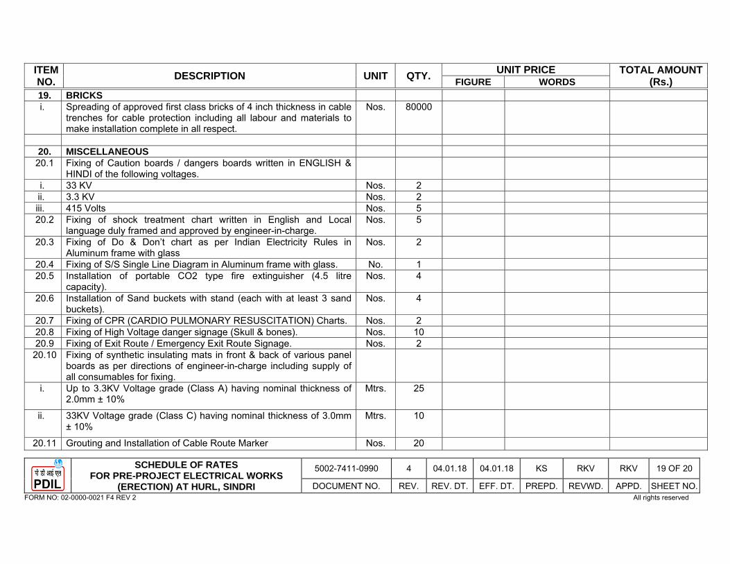
ITEM NO. DESCRIPTION UNIT QTY. UNIT PRICE TOTAL AMOUNT
(Rs.) FIGURE WORDS
SCHEDULE OF RATES FOR PRE-PROJECT ELECTRICAL WORKS
(ERECTION) AT HURL, SINDRI
5002-7411-0990 4 04.01.18 04.01.18 KS RKV RKV 19 OF 20
DOCUMENT NO. REV. REV. DT. EFF. DT. PREPD. REVWD. APPD. SHEET NO. FORM NO: 02-0000-0021 F4 REV 2 All rights reserved
19. BRICKS i. Spreading of approved first class bricks of 4 inch thickness in cable
trenches for cable protection including all labour and materials to make installation complete in all respect.
Nos. 80000
20. MISCELLANEOUS
20.1 Fixing of Caution boards / dangers boards written in ENGLISH & HINDI of the following voltages.
i. 33 KV Nos. 2 ii. 3.3 KV Nos. 2 iii. 415 Volts Nos. 5 20.2 Fixing of shock treatment chart written in English and Local
language duly framed and approved by engineer-in-charge. Nos. 5
20.3 Fixing of Do & Don’t chart as per Indian Electricity Rules in Aluminum frame with glass
Nos. 2
20.4 Fixing of S/S Single Line Diagram in Aluminum frame with glass. No. 1 20.5 Installation of portable CO2 type fire extinguisher (4.5 litre
capacity). Nos. 4
20.6 Installation of Sand buckets with stand (each with at least 3 sand buckets).
Nos. 4
20.7 Fixing of CPR (CARDIO PULMONARY RESUSCITATION) Charts. Nos. 2 20.8 Fixing of High Voltage danger signage (Skull & bones). Nos. 10 20.9 Fixing of Exit Route / Emergency Exit Route Signage. Nos. 2
20.10 Fixing of synthetic insulating mats in front & back of various panel boards as per directions of engineer-in-charge including supply of all consumables for fixing.
i. Up to 3.3KV Voltage grade (Class A) having nominal thickness of 2.0mm ± 10%
Mtrs. 25
ii. 33KV Voltage grade (Class C) having nominal thickness of 3.0mm ± 10%
Mtrs. 10
20.11 Grouting and Installation of Cable Route Marker Nos. 20
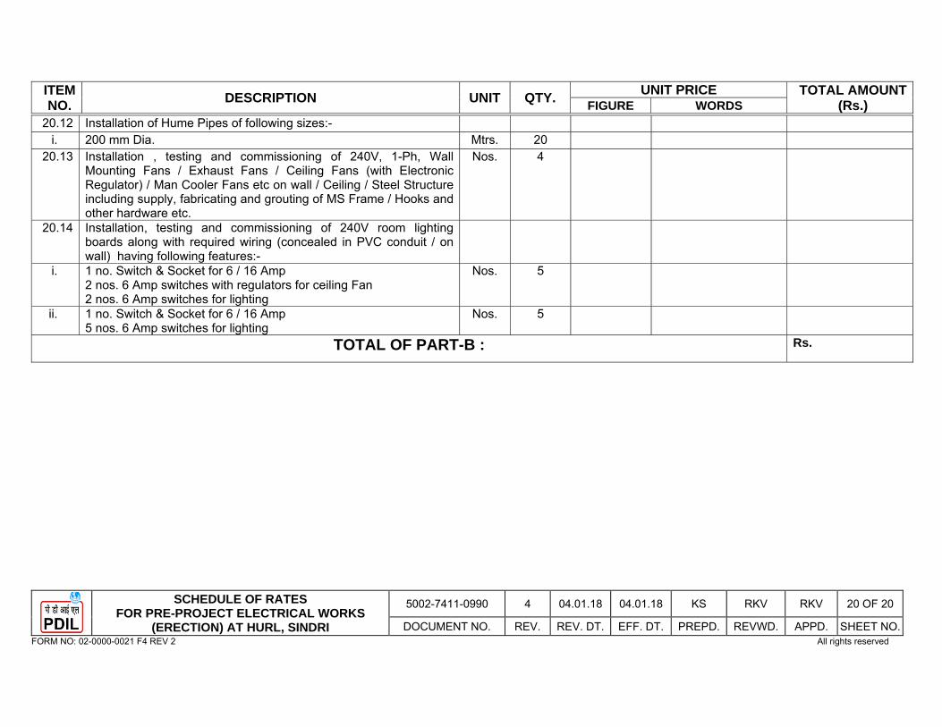
ITEM NO. DESCRIPTION UNIT QTY. UNIT PRICE TOTAL AMOUNT
(Rs.) FIGURE WORDS
SCHEDULE OF RATES FOR PRE-PROJECT ELECTRICAL WORKS
(ERECTION) AT HURL, SINDRI
5002-7411-0990 4 04.01.18 04.01.18 KS RKV RKV 20 OF 20
DOCUMENT NO. REV. REV. DT. EFF. DT. PREPD. REVWD. APPD. SHEET NO. FORM NO: 02-0000-0021 F4 REV 2 All rights reserved
20.12 Installation of Hume Pipes of following sizes:- i. 200 mm Dia. Mtrs. 20
20.13 Installation , testing and commissioning of 240V, 1-Ph, Wall Mounting Fans / Exhaust Fans / Ceiling Fans (with Electronic Regulator) / Man Cooler Fans etc on wall / Ceiling / Steel Structure including supply, fabricating and grouting of MS Frame / Hooks and other hardware etc.
Nos. 4
20.14 Installation, testing and commissioning of 240V room lighting boards along with required wiring (concealed in PVC conduit / on wall) having following features:-
i. 1 no. Switch & Socket for 6 / 16 Amp 2 nos. 6 Amp switches with regulators for ceiling Fan 2 nos. 6 Amp switches for lighting
Nos. 5
ii. 1 no. Switch & Socket for 6 / 16 Amp 5 nos. 6 Amp switches for lighting
Nos. 5
TOTAL OF PART-B : Rs.
31SCHEDULE OF RATES FOR CIVIL & STRUCTURAL WORKS FOR SUB STATION(CONSTRUCTION POWER) AT HURL,
SINDRI
0000-PNCV-SOR-SS-0201 1 26.12.17 26.12.17 ARUN RNS UPT Page 1 of 31
DOCUMENT NO REV REV DT EFF DT PREPD REVWD APPD SHEET NO FORM NO: 02-0000-0021 F4 REV 0 All rights reserved
PART-C
PREAMBLE TO
SCHEDULE OF RATES
FOR CIVIL, STRUCTURAL AND
OTHER ALLIED WORKS

31SCHEDULE OF RATES FOR CIVIL & STRUCTURAL WORKS FOR SUB STATION(CONSTRUCTION POWER) AT HURL,
SINDRI
0000-PNCV-SOR-SS-0201 1 26.12.17 26.12.17 ARUN RNS UPT Page 2 of 31
DOCUMENT NO REV REV DT EFF DT PREPD REVWD APPD SHEET NO FORM NO: 02-0000-0021 F4 REV 0 All rights reserved
1.00 GENERAL
1.01 The plans have been evolved tentatively based on information available with Owner / Consultant but the dimensions and details etc. are liable to changes. The Tenderers shall not be entitled to claim any higher rate or compensation on this account. The tender drawingsare intended mainly to give an indication of the probable type of construction. The successful Tenderers will, however, be required to execute the work as per detailed approved drawings issued to them from time to time. Steel structures can be changed to R.C.C. or vice versa. Owner reserves the right to add / delete any of the building works mentioned in the N.I.T., during the currency of the contract.
1.02 The Tenderers shall note that the quantities of the different Items, as given in the "Schedule of Rates" are tentative based on tentative tender drawings and are subject to variation and they shall not be entitled to claim any higher rate or compensation on this account.Owner / Consultant reserves the right to change / modify the size and type of sections at any time. Owner / Consultant does notguarantee work under each item of the Schedule of Quantities. The total quantum of work may vary up to 25% on either side and nothing extra will be paid on this account. Quantum of individual item may vary to any extent.
1.03 The Tenderers shall be fully responsible for the correct setting out and execution of the work in accordance with approved drawings which will be supplied to them progressively. All tools, tackles, construction equipments etc., required for the successful execution / construction of the complete work, shall be responsibility of the Tenderers.
1.04 The quantities given in the "Schedule of Rates" are approximate and are given only for the guidance for quoting rates. Payments on bills shall, however, be made on actual measurements of quantities of work done as per approved drawings. Unless otherwise specified,measurements of quantities shall be taken as per Indian Standards IS: 1200.
1.05 The rates to be inserted in the "Schedule of Rates" are to be inclusive of the value of the work described under several items including all costs and expenses which may be required for the construction of the work described together with all taxes, general risks, liabilities and obligations such as temporary buildings / hutments, fencing, watching, lighting, insurance, labour regulations, indemnity, maintenance and the like. The prices shall be inclusive of all labours, materials, tools, plants, equipment, hoists, tackles, scaffoldings,the sundries, etc., as may be necessary for the completion of the work in all respects.
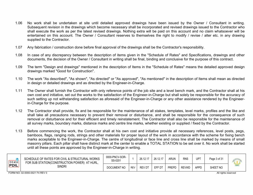
31SCHEDULE OF RATES FOR CIVIL & STRUCTURAL WORKS FOR SUB STATION(CONSTRUCTION POWER) AT HURL,
SINDRI
0000-PNCV-SOR-SS-0201 1 26.12.17 26.12.17 ARUN RNS UPT Page 3 of 31
DOCUMENT NO REV REV DT EFF DT PREPD REVWD APPD SHEET NO FORM NO: 02-0000-0021 F4 REV 0 All rights reserved
1.06 No work shall be undertaken at site until detailed approved drawings have been issued by the Owner / Consultant in writing.Subsequent revision in the drawings which become necessary shall be incorporated and revised drawings issued to the Contractor whoshall execute the work as per the latest revised drawings. Nothing extra will be paid on this account and no claim whatsoever will be entertained on this account. The Owner / Consultant reserves to themselves the right to modify / revise / alter etc. in any drawingsupplied to the Contractor.
1.07 Any fabrication / construction done before final approval of the drawings shall be the Contractor's responsibility.
1.08 In case of any discrepancy between the description of items given in the "Schedule of Rates" and Specifications, drawings and other documents, the decision of the Owner / Consultant in writing shall be final, binding and conclusive for the purpose of this contract.
1.09 The term "Design and drawings" mentioned in the description of Items in the "Schedule of Rates" means the detailed approved design drawings marked "Good for Construction".
1.10 The work "As described", "As shown", "As directed" or "As approved", "As mentioned" in the description of Items shall mean as directed in design or detailed drawings and as directed by the Engineer-in-Charge.
1.11 The Owner shall furnish the Contractor with only reference points of the job site and a level bench mark, and the Contractor shall at his own cost and initiative, set out the works to the satisfaction of the Engineer-in-Charge but shall solely be responsible for the accuracy of such setting up not withstanding satisfaction as aforesaid of the Engineer-in-Charge or any other assistance rendered by the Engineer-in-Charge for the purpose.
1.12 The Contractor shall provide, fix and be responsible for the maintenance of all stakes, templates, level marks, profiles and the like and shall take all precautions necessary to prevent their removal or disturbance, and shall be responsible for the consequence of suchremoval or disturbance and for their efficient and timely reinstatement. The Contractor shall also be responsible for the maintenance of all survey marks, boundary marks, distance marks and centre line marks, whether existing or supplied / fixed by the Contractor.
1.13 Before commencing the work, the Contractor shall at his own cost and initiative provide all necessary references, level posts, pegs, bamboos, flags, ranging rods, strings and other materials for proper layout of the work in accordance with the scheme for fixing bench marks acceptable to the Engineer-in-Charge. The centre of longitudinal or face line and cross line shall be marked by means of smallmasonry pillars. Each pillar shall have distinct mark at the center to enable a TOTAL STATION to be set over it. No work shall be started until all these points are approved by the Engineer-in-Charge in writing.

31SCHEDULE OF RATES FOR CIVIL & STRUCTURAL WORKS FOR SUB STATION(CONSTRUCTION POWER) AT HURL,
SINDRI
0000-PNCV-SOR-SS-0201 1 26.12.17 26.12.17 ARUN RNS UPT Page 4 of 31
DOCUMENT NO REV REV DT EFF DT PREPD REVWD APPD SHEET NO FORM NO: 02-0000-0021 F4 REV 0 All rights reserved
But such approval shall not relieve the Contractor of any of his responsibilities in respect of the adequacy or accuracy, thereof. The Contractor shall also provide all labour, material and other facilities necessary for the proper checking of layout and inspection of the points during construction.
1.14 Pillars bearing geodetic marks located at the site / unit of works under construction should be protected and fenced by the Contractor.
1.15 On completion of works, the Contractor must submit to the Engineer-in-Charge the geodetic documents according to which the work was carried out.
1.16 The Contractor shall be exclusively responsible for the provision and maintenance of horizontal and vertical alignments and levels and for the correctness of every part of the work in accordance there with and shall at his own cost rectify any errors or imperfectionstherein.
1.17 The Contractor shall at all times during the progress and continuance of the works be responsible for and effectively maintain and uphold in good, substantial, sound and perfect condition of all / and every part of works and shall make good from time to time and at all times as often as the Engineer-in-Charge shall require any damage or defect that may during the above period arise in or be any way connected with works.
1.18 The portion which is under HOLD shown in the approved drawing or the portion which would be brought under HOLD during executionon account of coordinating different activities of other working agencies shall be taken up by the Contractor to execution only after the said HOLD is withdrawn. The Contractor on this account shall not be entitled to claim for any compensation.
1.19 The Contractor shall maintain adequate drainage facilities at the work site at all times during the execution of the work.
1.20 No compensation shall be made by the Owner / Consultant for any damage done by rain or traffic during the execution of the work.
1.21 The Contractor shall afford all reasonable facilities such as scaffolding etc., and cooperation to the various other agencies and Contractors, for services not included in this contract, who may be working on the site simultaneously so that entire work can proceedsmoothly and simultaneously to a successful completion. The Tenderer must take all the aforesaid factors into consideration whilequoting his rates. Nothing extra shall be paid on any ground out of or relating to the aforesaid factors.
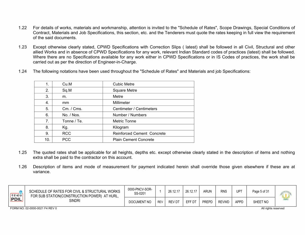
31SCHEDULE OF RATES FOR CIVIL & STRUCTURAL WORKS FOR SUB STATION(CONSTRUCTION POWER) AT HURL,
SINDRI
0000-PNCV-SOR-SS-0201 1 26.12.17 26.12.17 ARUN RNS UPT Page 5 of 31
DOCUMENT NO REV REV DT EFF DT PREPD REVWD APPD SHEET NO FORM NO: 02-0000-0021 F4 REV 0 All rights reserved
1.22 For details of works, materials and workmanship, attention is invited to the "Schedule of Rates", Scope Drawings, Special Conditions of Contract, Materials and Job Specifications, this section, etc. and the Tenderers must quote the rates keeping in full view the requirementof the said documents.
1.23 Except otherwise clearly stated, CPWD Specifications with Correction Slips ( latest) shall be followed in all Civil, Structural and other allied Works and in absence of CPWD Specifications for any work, relevant Indian Standard codes of practices (latest) shall be followed.Where there are no Specifications available for any work either in CPWD Specifications or in IS Codes of practices, the work shall be carried out as per the direction of Engineer-in-Charge.
1.24 The following notations have been used throughout the "Schedule of Rates" and Materials and job Specifications:
1. Cu.M Cubic Metre 2. Sq.M Square Metre 3. m. Metre 4. mm Millimeter 5. Cm. / Cms. Centimeter / Centimeters 6. No. / Nos. Number / Numbers 7. Tonne / Te. Metric Tonne 8. Kg. Kilogram 9. RCC Reinforced Cement Concrete
10. PCC Plain Cement Concrete
1.25 The quoted rates shall be applicable for all heights, depths etc. except otherwise clearly stated in the description of items and nothing extra shall be paid to the contractor on this account.
1.26 Description of items and mode of measurement for payment indicated herein shall override those given elsewhere if these are at variance.

31SCHEDULE OF RATES FOR CIVIL & STRUCTURAL WORKS FOR SUB STATION(CONSTRUCTION POWER) AT HURL,
SINDRI
0000-PNCV-SOR-SS-0201 1 26.12.17 26.12.17 ARUN RNS UPT Page 6 of 31
DOCUMENT NO REV REV DT EFF DT PREPD REVWD APPD SHEET NO FORM NO: 02-0000-0021 F4 REV 0 All rights reserved
1.27 Any materials / accessories / fittings etc. which may not be specifically mentioned in the description of items but which are normally used or necessary are to be provided by the contractor without any extra cost to Owner / Consultant and the work must be completed in all respects.
2.00 DEFINITION OF PLINTH
2.01 The portion of a structure between the surface of the finished ground and the surface of the floor immediately above the ground will be considered as plinth, which is generally 300 mm to 600 mm above finished ground level of the site area.
2.02 Plinth Level as shown in the drawing shall be treated as plinth level for the purpose of payment.
3.00 MATERIALS
3.01 The supply / procurement of all materials, required for the job, shall be the responsibility of the Contractor unless otherwise stated in the "Schedule of Rates" and elsewhere in the tender documents. The quality of the materials procured by the Contractor shall be subject to the approval of Engineer-in-Charge or his authorized representative before the materials are allowed to be used in the works. All the materials to be procured by the Contractor shall be in conformity with the CPWD Specifications with correction slips (latest) and in absence of which as laid down in the relevant Indian Standard Codes of practices (latest).
3.02 Transport of all materials shall be the Contractor's responsibility and it shall be at their own risk and cost.
3.03 The Engineer-in-Charge shall determine the suitability of materials to be used on the job and the Contractor shall get all materials approved by the Engineer-in-Charge. Any material procured and brought to site by the Contractor, found not to conform to the specifications and does not meet the approval of the Engineer-in-Charge, for use, will be rejected, and the Contractor shall remove and dispose off the same at his own cost and he shall not have any claim for compensation in this regard.
4.00 TESTS
4.01 According to the nature and importance of works, Owner / Consultant will demand the conduct of tests on concrete and other building materials etc., in which case the Contractor shall get the same done at his own cost in a laboratory to be approved by the Owner / Consultant.
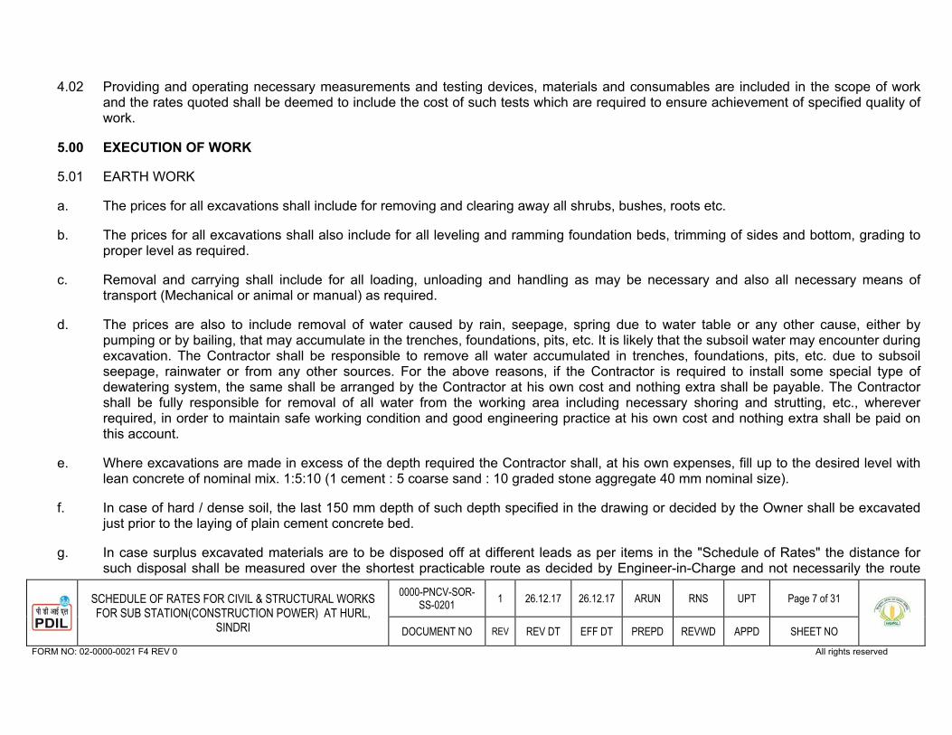
31SCHEDULE OF RATES FOR CIVIL & STRUCTURAL WORKS FOR SUB STATION(CONSTRUCTION POWER) AT HURL,
SINDRI
0000-PNCV-SOR-SS-0201 1 26.12.17 26.12.17 ARUN RNS UPT Page 7 of 31
DOCUMENT NO REV REV DT EFF DT PREPD REVWD APPD SHEET NO FORM NO: 02-0000-0021 F4 REV 0 All rights reserved
4.02 Providing and operating necessary measurements and testing devices, materials and consumables are included in the scope of work and the rates quoted shall be deemed to include the cost of such tests which are required to ensure achievement of specified quality of work.
5.00 EXECUTION OF WORK
5.01 EARTH WORK
a. The prices for all excavations shall include for removing and clearing away all shrubs, bushes, roots etc.
b. The prices for all excavations shall also include for all leveling and ramming foundation beds, trimming of sides and bottom, grading to proper level as required.
c. Removal and carrying shall include for all loading, unloading and handling as may be necessary and also all necessary means oftransport (Mechanical or animal or manual) as required.
d. The prices are also to include removal of water caused by rain, seepage, spring due to water table or any other cause, either by pumping or by bailing, that may accumulate in the trenches, foundations, pits, etc. It is likely that the subsoil water may encounter during excavation. The Contractor shall be responsible to remove all water accumulated in trenches, foundations, pits, etc. due to subsoilseepage, rainwater or from any other sources. For the above reasons, if the Contractor is required to install some special type of dewatering system, the same shall be arranged by the Contractor at his own cost and nothing extra shall be payable. The Contractorshall be fully responsible for removal of all water from the working area including necessary shoring and strutting, etc., whereverrequired, in order to maintain safe working condition and good engineering practice at his own cost and nothing extra shall be paid on this account.
e. Where excavations are made in excess of the depth required the Contractor shall, at his own expenses, fill up to the desired level with lean concrete of nominal mix. 1:5:10 (1 cement : 5 coarse sand : 10 graded stone aggregate 40 mm nominal size).
f. In case of hard / dense soil, the last 150 mm depth of such depth specified in the drawing or decided by the Owner shall be excavatedjust prior to the laying of plain cement concrete bed.
g. In case surplus excavated materials are to be disposed off at different leads as per items in the "Schedule of Rates" the distance for such disposal shall be measured over the shortest practicable route as decided by Engineer-in-Charge and not necessarily the route

31SCHEDULE OF RATES FOR CIVIL & STRUCTURAL WORKS FOR SUB STATION(CONSTRUCTION POWER) AT HURL,
SINDRI
0000-PNCV-SOR-SS-0201 1 26.12.17 26.12.17 ARUN RNS UPT Page 8 of 31
DOCUMENT NO REV REV DT EFF DT PREPD REVWD APPD SHEET NO FORM NO: 02-0000-0021 F4 REV 0 All rights reserved
actually taken by the Contractor for disposal. For the purpose of measurement of lead, the area excavated shall be divided into blocks (mutually agreed) and for each block the distance from center of the block to center of disposed material pertaining to this block shall be taken.
h. For payment of Earthwork in foundations / pits / trenches, etc., the excavation in earthwork volume shall be calculated by multiplying the base area as per the dimensions of mat (lean) concrete indicated in the drawing for different foundations by the specified depth of excavation considering vertical cut up to the bottom of mat concrete level from ground level. Extra excavation carried out by theContractor with sloping sides or with larger base area or with extra deepening of trenches / pits / foundations, etc. for workingconvenience shall not be measured and paid for.
The payment for back filling and disposal of surplus excavated material shall also be made on the same basis as that for excavation.Therefore excavation, back filling and disposal of surplus earth resulting from the excavation over the mat concrete dimensions and for the depth beyond bottom level of mat concrete as indicated in the drawings shall not be paid for. However, for the cases where waterproofing / acid proofing is indicated as per drawings on outer sides, the mode of measurement shall be as per IS: 1200.
i. Nothing extra shall be paid for sorting / screening of the excavated materials to obtain good earth for filling.
j. Nothing extra shall be paid on account of any lift for disposal of excavated materials.
k. Proper precautions shall be taken during the excavations to prevent any damage to the existing structures, pipes, sewer lines etc. If such damage occurs, it shall be rectified by the Contractor at his own expense.
5.02 PLAIN AND REINFORCED CEMENT CONCRETE WORKS
a. The prices for concrete beds and slabs are to include for laying on any type of subgrade, laying to falls or camber and for preparingsurface to receive concrete.
b. All concrete surfaces shall be finished to a fair face to give smooth and even surfaces and nothing extra shall be paid on this account.
c. The prices are to include leaving pockets, cutouts and holes and to provide wooden boxes or any other suitable arrangement in R.C.C for providing pockets for bolts as per approved working drawings and nothing extra shall be paid on this account.

31SCHEDULE OF RATES FOR CIVIL & STRUCTURAL WORKS FOR SUB STATION(CONSTRUCTION POWER) AT HURL,
SINDRI
0000-PNCV-SOR-SS-0201 1 26.12.17 26.12.17 ARUN RNS UPT Page 9 of 31
DOCUMENT NO REV REV DT EFF DT PREPD REVWD APPD SHEET NO FORM NO: 02-0000-0021 F4 REV 0 All rights reserved
d. All pockets / holes are to be properly covered by suitable means, so that dirt, rain water etc., should not enter the pockets / holes etc. No deduction in R.C.C quantity shall be made for pockets and nothing extra shall be paid for providing pockets as mentioned in para 5.02c above.
e. For measurement of openings in plain concrete / R.C.C work, refer clause No. 4.13 of IS: 1200 (Part-3).
f. Threads of bolts etc., which have already been fixed in the pockets, are to be greased and properly covered with gunny bags orpolythene sheet to protect it from damage from all sources and nothing extra shall be paid on this account.
g. The prices shall include for all rebating, throating, chamfering, weathering, moulding etc. to accord with the details shown in the approved working drawings.
h. Nothing extra shall be paid for any intricate work for foundation of equipments and machinery (Static / Dynamic) in R.C.C walls and other superstructure work or in concreting in small and thin sections in P.C.C or R.C.C work.
i. The prices for concrete are to include for hoisting and / or lowering to any heights and / or depth required and in any type of form work, packing around reinforcement wherever required and finishing the surfaces to fair and even surfaces.
j. The prices shall include for working up or hacking of concrete surface for providing keys for further concrete work and shall also include all plane, rebated or grooved construction and other joints.
k. All reinforced cement concrete used shall be of controlled concrete with designed mix and weigh batched conforming to IS : 456 unless otherwise specified. In all concrete and R.C.C work, broken graded coarse aggregate shall be used. The design mixes of concrete of different grades shall be established at the beginning of the work considering the required workability. However, if batching plant facility is not available, only nominal mix concrete is permissible.
l. Concrete admixtures for workability, if necessary, may be used in R.C.C., if decided by the Engineer-in-Charge. No extra payment for material or mixing etc. shall be made on this account.
m. Machine and equipment foundations shall mean all foundations including pedestals of vessels, towers, pumps, compressors, motors or any other equipment or machinery (both static and dynamic), pipe supports etc., and / or the like.
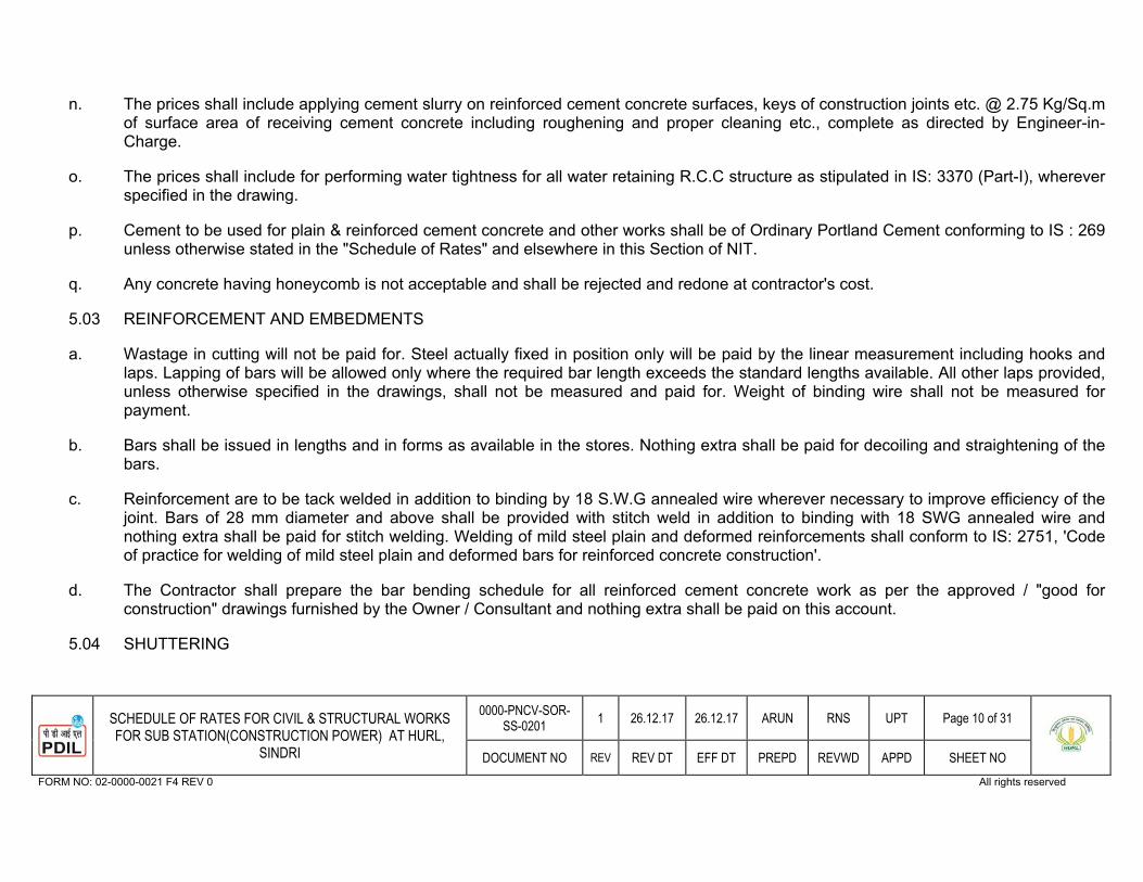
31SCHEDULE OF RATES FOR CIVIL & STRUCTURAL WORKS FOR SUB STATION(CONSTRUCTION POWER) AT HURL,
SINDRI
0000-PNCV-SOR-SS-0201 1 26.12.17 26.12.17 ARUN RNS UPT Page 10 of 31
DOCUMENT NO REV REV DT EFF DT PREPD REVWD APPD SHEET NO FORM NO: 02-0000-0021 F4 REV 0 All rights reserved
n. The prices shall include applying cement slurry on reinforced cement concrete surfaces, keys of construction joints etc. @ 2.75 Kg/Sq.m of surface area of receiving cement concrete including roughening and proper cleaning etc., complete as directed by Engineer-in-Charge.
o. The prices shall include for performing water tightness for all water retaining R.C.C structure as stipulated in IS: 3370 (Part-I), wherever specified in the drawing.
p. Cement to be used for plain & reinforced cement concrete and other works shall be of Ordinary Portland Cement conforming to IS : 269 unless otherwise stated in the "Schedule of Rates" and elsewhere in this Section of NIT.
q. Any concrete having honeycomb is not acceptable and shall be rejected and redone at contractor's cost.
5.03 REINFORCEMENT AND EMBEDMENTS
a. Wastage in cutting will not be paid for. Steel actually fixed in position only will be paid by the linear measurement including hooks and laps. Lapping of bars will be allowed only where the required bar length exceeds the standard lengths available. All other laps provided, unless otherwise specified in the drawings, shall not be measured and paid for. Weight of binding wire shall not be measured forpayment.
b. Bars shall be issued in lengths and in forms as available in the stores. Nothing extra shall be paid for decoiling and straightening of the bars.
c. Reinforcement are to be tack welded in addition to binding by 18 S.W.G annealed wire wherever necessary to improve efficiency of the joint. Bars of 28 mm diameter and above shall be provided with stitch weld in addition to binding with 18 SWG annealed wire andnothing extra shall be paid for stitch welding. Welding of mild steel plain and deformed reinforcements shall conform to IS: 2751, 'Code of practice for welding of mild steel plain and deformed bars for reinforced concrete construction'.
d. The Contractor shall prepare the bar bending schedule for all reinforced cement concrete work as per the approved / "good forconstruction" drawings furnished by the Owner / Consultant and nothing extra shall be paid on this account.
5.04 SHUTTERING

31SCHEDULE OF RATES FOR CIVIL & STRUCTURAL WORKS FOR SUB STATION(CONSTRUCTION POWER) AT HURL,
SINDRI
0000-PNCV-SOR-SS-0201 1 26.12.17 26.12.17 ARUN RNS UPT Page 11 of 31
DOCUMENT NO REV REV DT EFF DT PREPD REVWD APPD SHEET NO FORM NO: 02-0000-0021 F4 REV 0 All rights reserved
a. The prices for shuttering shall include for providing splayed edges, notching, chamfering, allowances for overlaps and passing at angles, battens, strutting bolting, wedging, easing, striking and removing.
b. The concrete work should have ply wood / steel shuttering as not to require any plastering, after striking out the shuttering. Any concrete having honeycomb is not acceptable and is liable to be rejected and redone at Contractor's cost.
c. The prices are also to include for all necessary supports, struts, braces, etc., dressing with shuttering compound and / or other approved method to prevent adhesion between concrete and form work and all raking for circular cutting and waste.
d. The prices shall also include for all labour and materials necessary for providing form work at all heights and depths and includingstriking, dismantling the form work assembly etc. after the necessary stripping period of concreting is over and also making all the joints in shuttering fully leak-proof providing low density polythene sheets / bitumen paper.
e. The prices shall also include for forming detailed design required for the form work and / or all other sundry labour.
f. All shuttering shall be either plywood or steel shuttering to produce plain, smooth and even surfaces, which will thus be integrallyfinished. If any impressions of the shuttering joints are noticed after the striking of the shuttering, the same should be treated by rubbing with Carborundum stones and nothing extra shall be paid on this account.
g. In case of dowel bars projecting out from R.C.C works such as columns, beams etc. nothing extra shall be paid for any special provision like making holes that may be required to be left in the form work.
5.05 MASONRY WORKS
The prices for brick work shall include the following:
a. Fair face of brick work with selected brick with class designation 75 or as specified in the description of relevant Items in the "Schedule of Rates" from the lot.
b. Raking out joints for plastering and pointing done as separate process of finishing joints, flush as the work proceeds.
c. All rough and / or fair cutting and waste unless specifically stated otherwise.
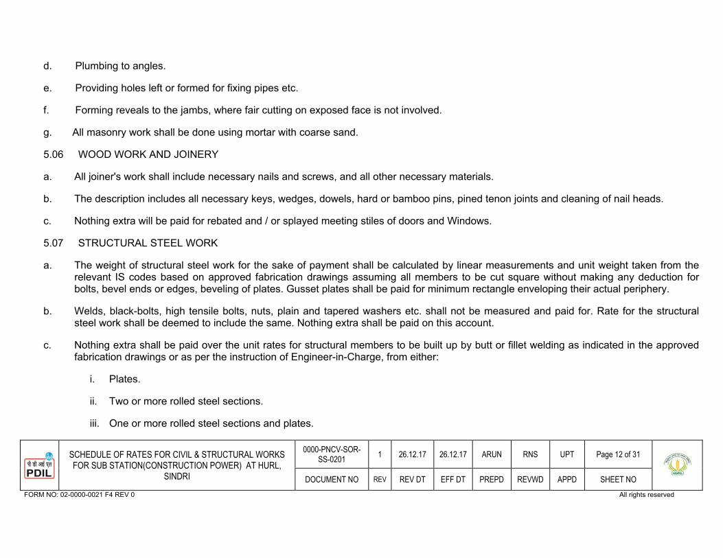
31SCHEDULE OF RATES FOR CIVIL & STRUCTURAL WORKS FOR SUB STATION(CONSTRUCTION POWER) AT HURL,
SINDRI
0000-PNCV-SOR-SS-0201 1 26.12.17 26.12.17 ARUN RNS UPT Page 12 of 31
DOCUMENT NO REV REV DT EFF DT PREPD REVWD APPD SHEET NO FORM NO: 02-0000-0021 F4 REV 0 All rights reserved
d. Plumbing to angles.
e. Providing holes left or formed for fixing pipes etc.
f. Forming reveals to the jambs, where fair cutting on exposed face is not involved.
g. All masonry work shall be done using mortar with coarse sand.
5.06 WOOD WORK AND JOINERY
a. All joiner's work shall include necessary nails and screws, and all other necessary materials.
b. The description includes all necessary keys, wedges, dowels, hard or bamboo pins, pined tenon joints and cleaning of nail heads.
c. Nothing extra will be paid for rebated and / or splayed meeting stiles of doors and Windows.
5.07 STRUCTURAL STEEL WORK
a. The weight of structural steel work for the sake of payment shall be calculated by linear measurements and unit weight taken from the relevant IS codes based on approved fabrication drawings assuming all members to be cut square without making any deduction forbolts, bevel ends or edges, beveling of plates. Gusset plates shall be paid for minimum rectangle enveloping their actual periphery.
b. Welds, black-bolts, high tensile bolts, nuts, plain and tapered washers etc. shall not be measured and paid for. Rate for the structural steel work shall be deemed to include the same. Nothing extra shall be paid on this account.
c. Nothing extra shall be paid over the unit rates for structural members to be built up by butt or fillet welding as indicated in the approved fabrication drawings or as per the instruction of Engineer-in-Charge, from either:
i. Plates.
ii. Two or more rolled steel sections.
iii. One or more rolled steel sections and plates.
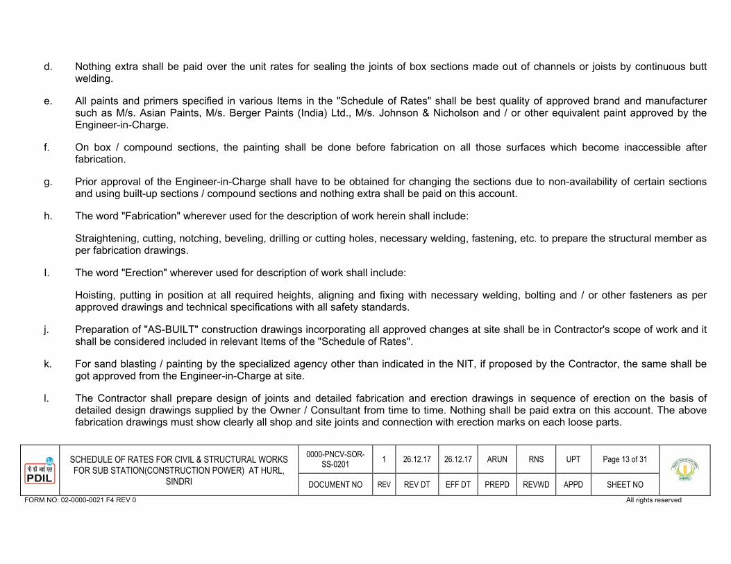
31SCHEDULE OF RATES FOR CIVIL & STRUCTURAL WORKS FOR SUB STATION(CONSTRUCTION POWER) AT HURL,
SINDRI
0000-PNCV-SOR-SS-0201 1 26.12.17 26.12.17 ARUN RNS UPT Page 13 of 31
DOCUMENT NO REV REV DT EFF DT PREPD REVWD APPD SHEET NO FORM NO: 02-0000-0021 F4 REV 0 All rights reserved
d. Nothing extra shall be paid over the unit rates for sealing the joints of box sections made out of channels or joists by continuous butt welding.
e. All paints and primers specified in various Items in the "Schedule of Rates" shall be best quality of approved brand and manufacturersuch as M/s. Asian Paints, M/s. Berger Paints (India) Ltd., M/s. Johnson & Nicholson and / or other equivalent paint approved by the Engineer-in-Charge.
f. On box / compound sections, the painting shall be done before fabrication on all those surfaces which become inaccessible afterfabrication.
g. Prior approval of the Engineer-in-Charge shall have to be obtained for changing the sections due to non-availability of certain sections and using built-up sections / compound sections and nothing extra shall be paid on this account.
h. The word "Fabrication" wherever used for the description of work herein shall include:
Straightening, cutting, notching, beveling, drilling or cutting holes, necessary welding, fastening, etc. to prepare the structural member as per fabrication drawings.
I. The word "Erection" wherever used for description of work shall include:
Hoisting, putting in position at all required heights, aligning and fixing with necessary welding, bolting and / or other fasteners as per approved drawings and technical specifications with all safety standards.
j. Preparation of "AS-BUILT" construction drawings incorporating all approved changes at site shall be in Contractor's scope of work and it shall be considered included in relevant Items of the "Schedule of Rates".
k. For sand blasting / painting by the specialized agency other than indicated in the NIT, if proposed by the Contractor, the same shall be got approved from the Engineer-in-Charge at site.
l. The Contractor shall prepare design of joints and detailed fabrication and erection drawings in sequence of erection on the basis of detailed design drawings supplied by the Owner / Consultant from time to time. Nothing shall be paid extra on this account. The above fabrication drawings must show clearly all shop and site joints and connection with erection marks on each loose parts.

31SCHEDULE OF RATES FOR CIVIL & STRUCTURAL WORKS FOR SUB STATION(CONSTRUCTION POWER) AT HURL,
SINDRI
0000-PNCV-SOR-SS-0201 1 26.12.17 26.12.17 ARUN RNS UPT Page 14 of 31
DOCUMENT NO REV REV DT EFF DT PREPD REVWD APPD SHEET NO FORM NO: 02-0000-0021 F4 REV 0 All rights reserved
m. The Contractor shall submit his design calculations for the design of joints. All joints shall be designed for full strength of the members or otherwise as indicated in the design drawings.
n. The design calculations of joints and fabrication drawings will be checked and approved by the Owner / Consultant as per mutuallyagreed time schedule and the Contractor should strictly adhere to these approved drawings and specifications. Fabrication work shall be taken up only with the approved fabrication drawings.
5.08 STEEL AND ALUMINIUM DOORS, WINDOWS & VENTILATORS
a. The prices are to include for necessary hardware fittings and fixtures as specified and fixing to frames with necessary lugs etc., all necessary chases, holes, etc., grouting of holes and making good to match after doors, windows and ventilators, etc. are fixed. The price of steel doors / windows / ventilators is also to include application of required primer and paint of approved shade, make and manufacturer.
b. The prices shall also to include for providing good quality glass panes of required thickness as indicated in the "Schedule of Rates".
5.09 FLOORS AND BASES
a. The price for hard core shall include for all labour in laying to falls or camber, hand packing, edges of haunches forming splayed edges, watering and rolling with power driven roller and ramming wherever required to solid compaction.
b. The prices shall include also for works at all heights and depths.
5.10 FINISHING WORKS
a. The prices shall include for work at any height / depth and for all necessary scaffolding etc. as required.
b. The prices shall include for providing and laying of materials for all the Items of plaster and also raking to form key for plaster and for all work in narrow width, formed angles, chamfered external angles and for making good the faces.
5.11 MISCELLANEOUS
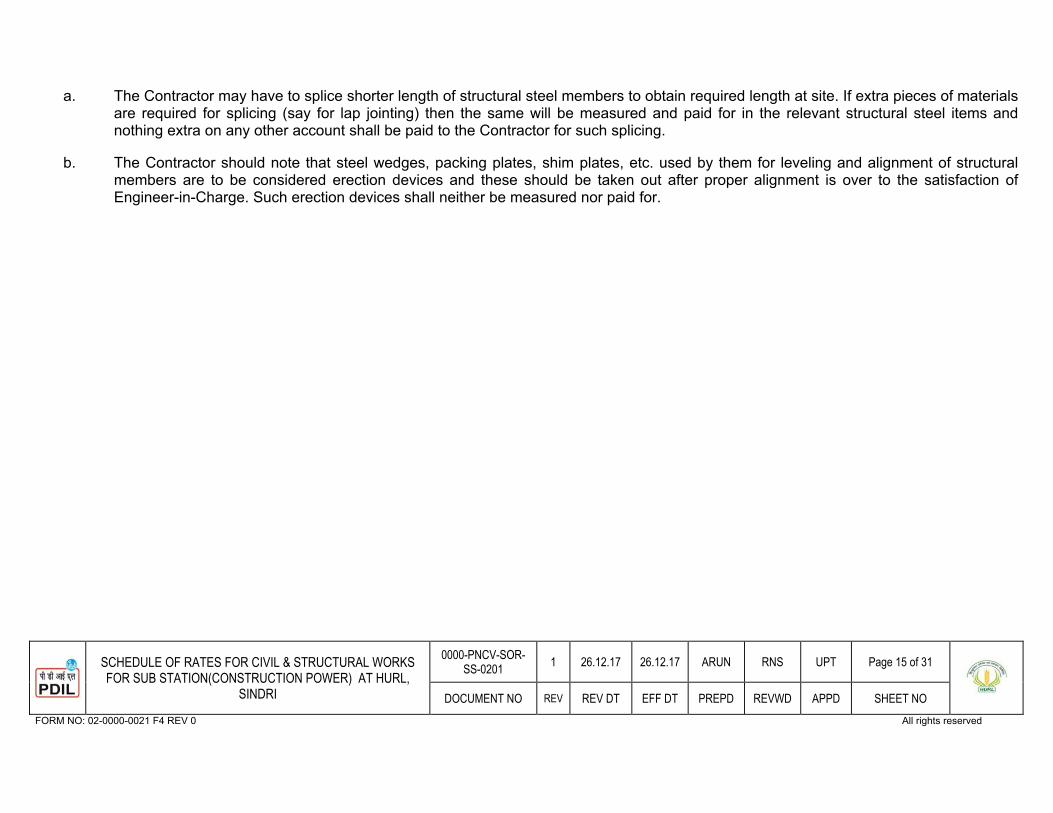
31SCHEDULE OF RATES FOR CIVIL & STRUCTURAL WORKS FOR SUB STATION(CONSTRUCTION POWER) AT HURL,
SINDRI
0000-PNCV-SOR-SS-0201 1 26.12.17 26.12.17 ARUN RNS UPT Page 15 of 31
DOCUMENT NO REV REV DT EFF DT PREPD REVWD APPD SHEET NO FORM NO: 02-0000-0021 F4 REV 0 All rights reserved
a. The Contractor may have to splice shorter length of structural steel members to obtain required length at site. If extra pieces of materials are required for splicing (say for lap jointing) then the same will be measured and paid for in the relevant structural steel items and nothing extra on any other account shall be paid to the Contractor for such splicing.
b. The Contractor should note that steel wedges, packing plates, shim plates, etc. used by them for leveling and alignment of structuralmembers are to be considered erection devices and these should be taken out after proper alignment is over to the satisfaction ofEngineer-in-Charge. Such erection devices shall neither be measured nor paid for.
31SCHEDULE OF RATES FOR CIVIL & STRUCTURAL WORKS FOR SUB STATION(CONSTRUCTION POWER) AT HURL,
SINDRI
0000-PNCV-SOR-SS-0201 1 26.12.17 26.12.17 ARUN RNS UPT Page 16 of 31
DOCUMENT NO REV REV DT EFF DT PREPD REVWD APPD SHEET NO FORM NO: 02-0000-0021 F4 REV 0 All rights reserved
PART-C
SCHEDULE OF RATES
FOR
CIVIL& STRUCTUAL WORKS
FOR
SUB STATION (CONSTRUCTION POWER)
AT
HURL, SINDRI
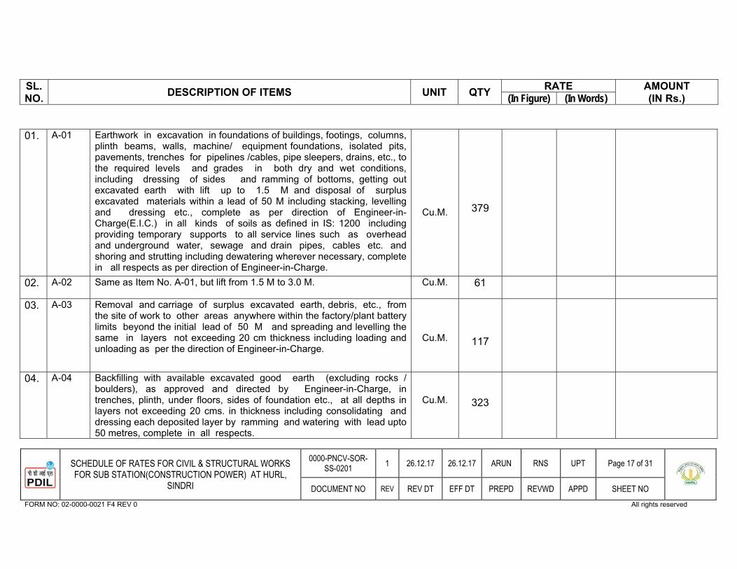
SL.NO. DESCRIPTION OF ITEMS UNIT QTY RATE AMOUNT
(IN Rs.) (In Figure) (In Words)
31SCHEDULE OF RATES FOR CIVIL & STRUCTURAL WORKS FOR SUB STATION(CONSTRUCTION POWER) AT HURL,
SINDRI
0000-PNCV-SOR-SS-0201 1 26.12.17 26.12.17 ARUN RNS UPT Page 17 of 31
DOCUMENT NO REV REV DT EFF DT PREPD REVWD APPD SHEET NO FORM NO: 02-0000-0021 F4 REV 0 All rights reserved
01. A-01 Earthwork in excavation in foundations of buildings, footings, columns,
plinth beams, walls, machine/ equipment foundations, isolated pits, pavements, trenches for pipelines /cables, pipe sleepers, drains, etc., to the required levels and grades in both dry and wet conditions, including dressing of sides and ramming of bottoms, getting out excavated earth with lift up to 1.5 M and disposal of surplus excavated materials within a lead of 50 M including stacking, levelling and dressing etc., complete as per direction of Engineer-in-Charge(E.I.C.) in all kinds of soils as defined in IS: 1200 including providing temporary supports to all service lines such as overhead and underground water, sewage and drain pipes, cables etc. and shoring and strutting including dewatering wherever necessary, complete in all respects as per direction of Engineer-in-Charge.
Cu.M. 379
02. A-02 Same as Item No. A-01, but lift from 1.5 M to 3.0 M. Cu.M. 61
03.
A-03
Removal and carriage of surplus excavated earth, debris, etc., from the site of work to other areas anywhere within the factory/plant battery limits beyond the initial lead of 50 M and spreading and levelling the same in layers not exceeding 20 cm thickness including loading and unloading as per the direction of Engineer-in-Charge.
Cu.M.
117
04. A-04 Backfilling with available excavated good earth (excluding rocks / boulders), as approved and directed by Engineer-in-Charge, in trenches, plinth, under floors, sides of foundation etc., at all depths in layers not exceeding 20 cms. in thickness including consolidating and dressing each deposited layer by ramming and watering with lead upto 50 metres, complete in all respects.
Cu.M. 323
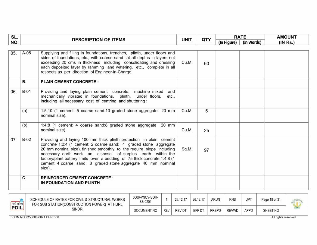
SL.NO. DESCRIPTION OF ITEMS UNIT QTY RATE AMOUNT
(IN Rs.) (In Figure) (In Words)
31SCHEDULE OF RATES FOR CIVIL & STRUCTURAL WORKS FOR SUB STATION(CONSTRUCTION POWER) AT HURL,
SINDRI
0000-PNCV-SOR-SS-0201 1 26.12.17 26.12.17 ARUN RNS UPT Page 18 of 31
DOCUMENT NO REV REV DT EFF DT PREPD REVWD APPD SHEET NO FORM NO: 02-0000-0021 F4 REV 0 All rights reserved
05. A-05 Supplying and filling in foundations, trenches, plinth, under floors and sides of foundations, etc., with coarse sand at all depths in layers not exceeding 20 cms in thickness including consolidating and dressing each deposited layer by ramming and watering, etc., complete in all respects as per direction of Engineer-in-Charge.
Cu.M. 60
B. PLAIN CEMENT CONCRETE :
06. B-01 Providing and laying plain cement concrete, machine mixed and mechanically vibrated in foundations, plinth, under floors, etc., including all necessary cost of centring and shuttering :
(a) 1:5:10 (1 cement: 5 coarse sand:10 graded stone aggregate 20 mm nominal size).
Cu.M. 5
(b) 1:4:8 (1 cement: 4 coarse sand:8 graded stone aggregate 20 mm nominal size).
Cu.M. 25
07. B-02 Providing and laying 100 mm thick plinth protection in plain cement concrete 1:2:4 (1 cement: 2 coarse sand: 4 graded stone aggregate 20 mm nominal size), finished smoothly to the require slope including necessary earth work an disposal of surplus earth within the factory/plant battery limits over a bedding of 75 thick concrete 1:4:8 (1 cement: 4 coarse sand: 8 graded stone aggregate 40 mm nominal size)..
Sq.M. 97
C. REINFORCED CEMENT CONCRETE : IN FOUNDATION AND PLINTH
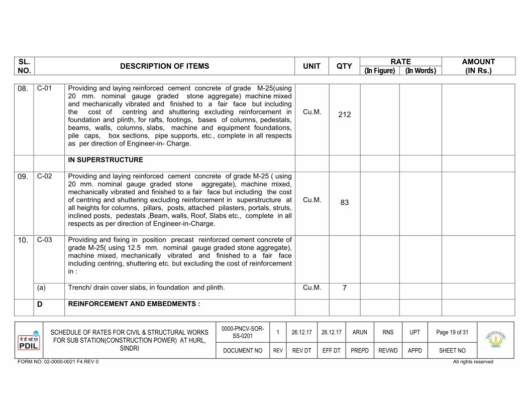
SL.NO. DESCRIPTION OF ITEMS UNIT QTY RATE AMOUNT
(IN Rs.) (In Figure) (In Words)
31SCHEDULE OF RATES FOR CIVIL & STRUCTURAL WORKS FOR SUB STATION(CONSTRUCTION POWER) AT HURL,
SINDRI
0000-PNCV-SOR-SS-0201 1 26.12.17 26.12.17 ARUN RNS UPT Page 19 of 31
DOCUMENT NO REV REV DT EFF DT PREPD REVWD APPD SHEET NO FORM NO: 02-0000-0021 F4 REV 0 All rights reserved
08. C-01 Providing and laying reinforced cement concrete of grade M-25(using 20 mm. nominal gauge graded stone aggregate) machine mixed and mechanically vibrated and finished to a fair face but including the cost of centring and shuttering excluding reinforcement in foundation and plinth, for rafts, footings, bases of columns, pedestals, beams, walls, columns, slabs, machine and equipment foundations, pile caps, box sections, pipe supports, etc., complete in all respects as per direction of Engineer-in- Charge.
Cu.M.
212
IN SUPERSTRUCTURE
09. C-02 Providing and laying reinforced cement concrete of grade M-25 ( using 20 mm. nominal gauge graded stone aggregate), machine mixed, mechanically vibrated and finished to a fair face but including the cost of centring and shuttering excluding reinforcement in superstructure at all heights for columns, pillars, posts, attached pilasters, portals, struts, inclined posts, pedestals ,Beam, walls, Roof, Slabs etc., complete in all respects as per direction of Engineer-in-Charge.
Cu.M. 83
10. C-03 Providing and fixing in position precast reinforced cement concrete of grade M-25( using 12.5 mm. nominal gauge graded stone aggregate), machine mixed, mechanically vibrated and finished to a fair face including centring, shuttering etc. but excluding the cost of reinforcement in :
(a) Trench/ drain cover slabs, in foundation and plinth. Cu.M. 7
D REINFORCEMENT AND EMBEDMENTS :
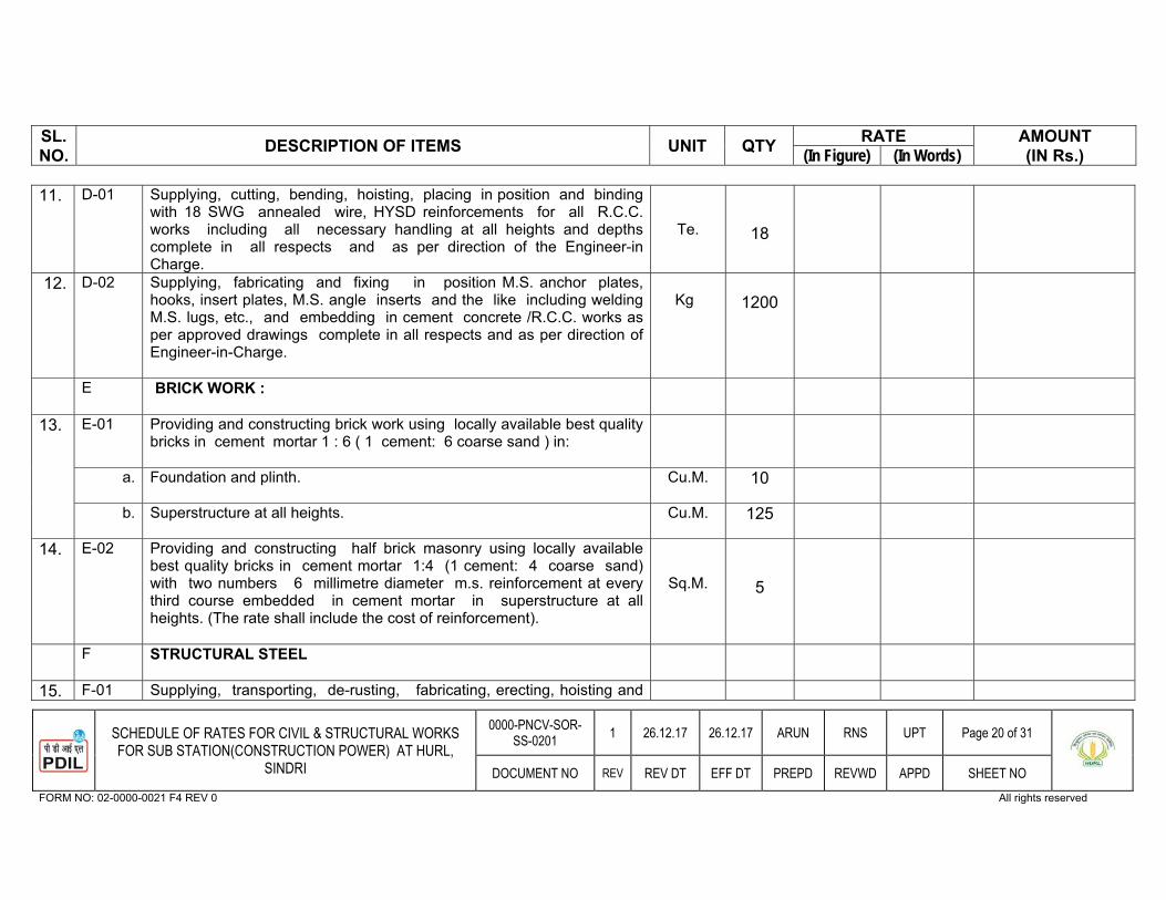
SL.NO. DESCRIPTION OF ITEMS UNIT QTY RATE AMOUNT
(IN Rs.) (In Figure) (In Words)
31SCHEDULE OF RATES FOR CIVIL & STRUCTURAL WORKS FOR SUB STATION(CONSTRUCTION POWER) AT HURL,
SINDRI
0000-PNCV-SOR-SS-0201 1 26.12.17 26.12.17 ARUN RNS UPT Page 20 of 31
DOCUMENT NO REV REV DT EFF DT PREPD REVWD APPD SHEET NO FORM NO: 02-0000-0021 F4 REV 0 All rights reserved
11. D-01 Supplying, cutting, bending, hoisting, placing in position and binding with 18 SWG annealed wire, HYSD reinforcements for all R.C.C. works including all necessary handling at all heights and depths complete in all respects and as per direction of the Engineer-in Charge.
Te. 18
12. D-02 Supplying, fabricating and fixing in position M.S. anchor plates, hooks, insert plates, M.S. angle inserts and the like including welding M.S. lugs, etc., and embedding in cement concrete /R.C.C. works as per approved drawings complete in all respects and as per direction of Engineer-in-Charge.
Kg 1200
E BRICK WORK :
13. E-01 Providing and constructing brick work using locally available best quality bricks in cement mortar 1 : 6 ( 1 cement: 6 coarse sand ) in:
a. Foundation and plinth. Cu.M. 10
b. Superstructure at all heights. Cu.M. 125
14. E-02 Providing and constructing half brick masonry using locally available best quality bricks in cement mortar 1:4 (1 cement: 4 coarse sand) with two numbers 6 millimetre diameter m.s. reinforcement at every third course embedded in cement mortar in superstructure at all heights. (The rate shall include the cost of reinforcement).
Sq.M. 5
F STRUCTURAL STEEL
15. F-01 Supplying, transporting, de-rusting, fabricating, erecting, hoisting and
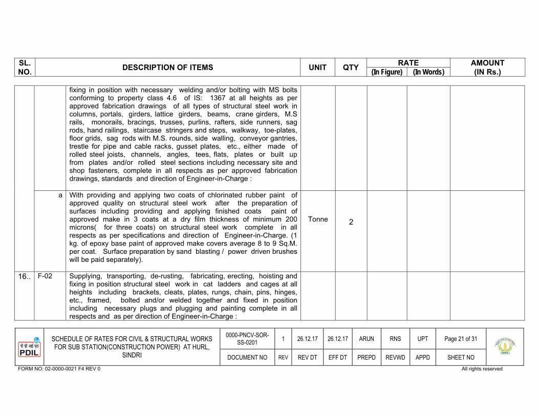
SL.NO. DESCRIPTION OF ITEMS UNIT QTY RATE AMOUNT
(IN Rs.) (In Figure) (In Words)
31SCHEDULE OF RATES FOR CIVIL & STRUCTURAL WORKS FOR SUB STATION(CONSTRUCTION POWER) AT HURL,
SINDRI
0000-PNCV-SOR-SS-0201 1 26.12.17 26.12.17 ARUN RNS UPT Page 21 of 31
DOCUMENT NO REV REV DT EFF DT PREPD REVWD APPD SHEET NO FORM NO: 02-0000-0021 F4 REV 0 All rights reserved
fixing in position with necessary welding and/or bolting with MS bolts conforming to property class 4.6 of IS: 1367 at all heights as per approved fabrication drawings of all types of structural steel work in columns, portals, girders, lattice girders, beams, crane girders, M.S rails, monorails, bracings, trusses, purlins, rafters, side runners, sag rods, hand railings, staircase stringers and steps, walkway, toe-plates, floor grids, sag rods with M.S. rounds, side walling, conveyor gantries, trestle for pipe and cable racks, gusset plates, etc., either made of rolled steel joists, channels, angles, tees, flats, plates or built up from plates and/or rolled steel sections including necessary site and shop fasteners, complete in all respects as per approved fabrication drawings, standards and direction of Engineer-in-Charge :
a With providing and applying two coats of chlorinated rubber paint of approved quality on structural steel work after the preparation of surfaces including providing and applying finished coats paint of approved make in 3 coats at a dry film thickness of minimum 200 microns( for three coats) on structural steel work complete in all respects as per specifications and direction of Engineer-in-Charge. (1 kg. of epoxy base paint of approved make covers average 8 to 9 Sq.M. per coat. Surface preparation by sand blasting / power driven brushes will be paid separately).
Tonne
2
16.. F-02 Supplying, transporting, de-rusting, fabricating, erecting, hoisting and fixing in position structural steel work in cat ladders and cages at all heights including brackets, cleats, plates, rungs, chain, pins, hinges, etc., framed, bolted and/or welded together and fixed in position including necessary plugs and plugging and painting complete in all respects and as per direction of Engineer-in-Charge :

SL.NO. DESCRIPTION OF ITEMS UNIT QTY RATE AMOUNT
(IN Rs.) (In Figure) (In Words)
31SCHEDULE OF RATES FOR CIVIL & STRUCTURAL WORKS FOR SUB STATION(CONSTRUCTION POWER) AT HURL,
SINDRI
0000-PNCV-SOR-SS-0201 1 26.12.17 26.12.17 ARUN RNS UPT Page 22 of 31
DOCUMENT NO REV REV DT EFF DT PREPD REVWD APPD SHEET NO FORM NO: 02-0000-0021 F4 REV 0 All rights reserved
a. With providing and applying two coats of chlorinated rubber paint of approved quality on structural steel work after the preparation of surfaces including providing and applying finished coats of approved make paint in 2 coats at a dry film thickness of minimum 200 microns( for four coats) on structural steel work complete in all respects as per specifications and direction of Engineer-in-Charge. ( 1 kg. covers average 8 to 9 Sq. M. per coat. Surface preparation by sand blasting/ power driven brushes will be paid separately).
Tonne
0.5
17. F-03 Providing, fabricating and fixing in position double leaf transformer gates of any height with one wicket door within the main gate, all made out of structural steel sections such as M.S. Angles, Tees, Channels, Plates, Flats, etc., for all horizontal, vertical and diagonal members, M.S. Gusset plates including providing and fixing in position at all heights hard drawn steel wire fabric mesh of size 75 mm x 25 mm and weight not less than 7.75 kg/sq.m. welded with frames, including providing and fixing necessary lock plate, handles, locking arrangement and other fittings, drilling of holes wherever required, welding etc. including providing necessary hinge plates welded to insert plates embedded in RCC columns, bolts and nuts for hinge etc. including providing and applying painting, complete in all respects as per drawings and direction of Engineer-in-Charge (M.S. insert plates embedded in RCC shall be paid separately) :
a. With providing and applying two coats of high build zinc phosphate primer of approved brand and manufacture compatible to chlorinated rubber paint at a dry film thickness of 50 micron per coat on structural
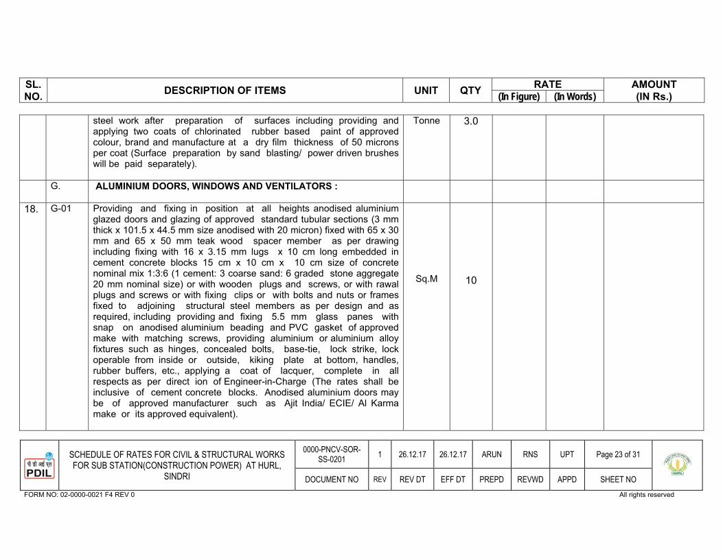
SL.NO. DESCRIPTION OF ITEMS UNIT QTY RATE AMOUNT
(IN Rs.) (In Figure) (In Words)
31SCHEDULE OF RATES FOR CIVIL & STRUCTURAL WORKS FOR SUB STATION(CONSTRUCTION POWER) AT HURL,
SINDRI
0000-PNCV-SOR-SS-0201 1 26.12.17 26.12.17 ARUN RNS UPT Page 23 of 31
DOCUMENT NO REV REV DT EFF DT PREPD REVWD APPD SHEET NO FORM NO: 02-0000-0021 F4 REV 0 All rights reserved
steel work after preparation of surfaces including providing and applying two coats of chlorinated rubber based paint of approved colour, brand and manufacture at a dry film thickness of 50 microns per coat (Surface preparation by sand blasting/ power driven brushes will be paid separately).
Tonne 3.0
G. ALUMINIUM DOORS, WINDOWS AND VENTILATORS :
18. G-01 Providing and fixing in position at all heights anodised aluminium glazed doors and glazing of approved standard tubular sections (3 mm thick x 101.5 x 44.5 mm size anodised with 20 micron) fixed with 65 x 30 mm and 65 x 50 mm teak wood spacer member as per drawing including fixing with 16 x 3.15 mm lugs x 10 cm long embedded in cement concrete blocks 15 cm x 10 cm x 10 cm size of concrete nominal mix 1:3:6 (1 cement: 3 coarse sand: 6 graded stone aggregate 20 mm nominal size) or with wooden plugs and screws, or with rawal plugs and screws or with fixing clips or with bolts and nuts or frames fixed to adjoining structural steel members as per design and as required, including providing and fixing 5.5 mm glass panes with snap on anodised aluminium beading and PVC gasket of approved make with matching screws, providing aluminium or aluminium alloy fixtures such as hinges, concealed bolts, base-tie, lock strike, lock operable from inside or outside, kiking plate at bottom, handles, rubber buffers, etc., applying a coat of lacquer, complete in all respects as per direct ion of Engineer-in-Charge (The rates shall be inclusive of cement concrete blocks. Anodised aluminium doors may be of approved manufacturer such as Ajit India/ ECIE/ Al Karma make or its approved equivalent).
Sq.M
10
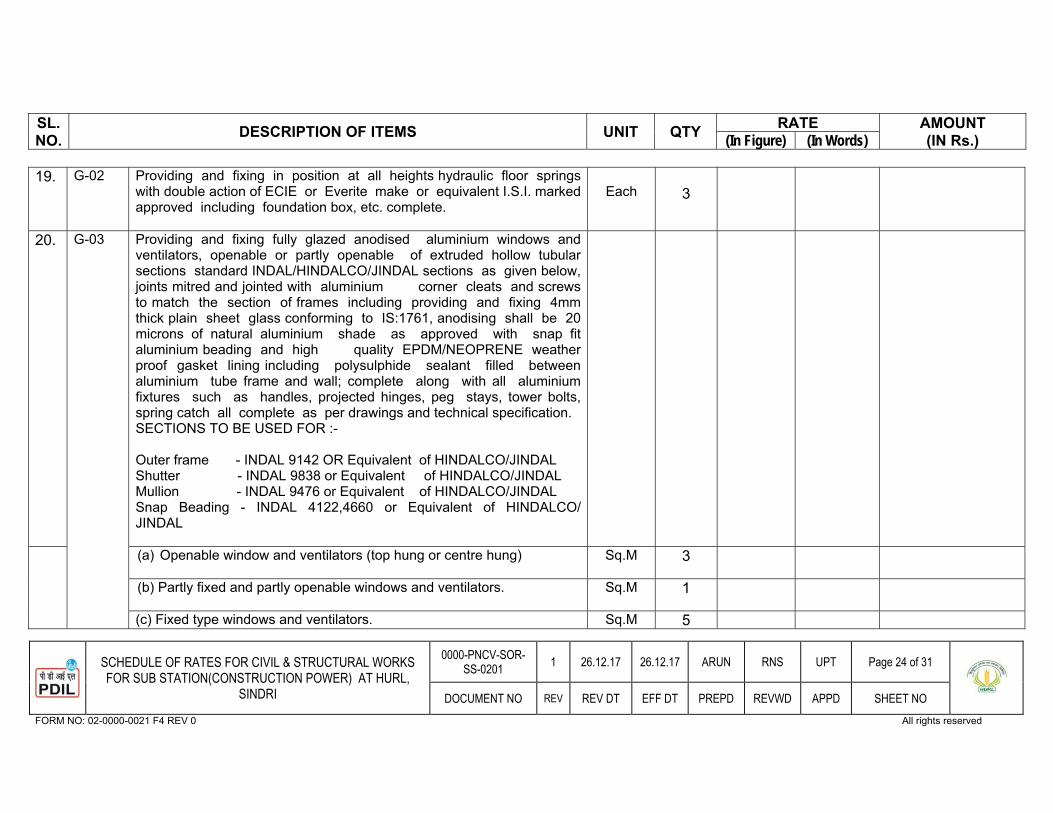
SL.NO. DESCRIPTION OF ITEMS UNIT QTY RATE AMOUNT
(IN Rs.) (In Figure) (In Words)
31SCHEDULE OF RATES FOR CIVIL & STRUCTURAL WORKS FOR SUB STATION(CONSTRUCTION POWER) AT HURL,
SINDRI
0000-PNCV-SOR-SS-0201 1 26.12.17 26.12.17 ARUN RNS UPT Page 24 of 31
DOCUMENT NO REV REV DT EFF DT PREPD REVWD APPD SHEET NO FORM NO: 02-0000-0021 F4 REV 0 All rights reserved
19. G-02 Providing and fixing in position at all heights hydraulic floor springs with double action of ECIE or Everite make or equivalent I.S.I. marked approved including foundation box, etc. complete.
Each 3
20. G-03 Providing and fixing fully glazed anodised aluminium windows and ventilators, openable or partly openable of extruded hollow tubular sections standard INDAL/HINDALCO/JINDAL sections as given below, joints mitred and jointed with aluminium corner cleats and screws to match the section of frames including providing and fixing 4mm thick plain sheet glass conforming to IS:1761, anodising shall be 20 microns of natural aluminium shade as approved with snap fit aluminium beading and high quality EPDM/NEOPRENE weather proof gasket lining including polysulphide sealant filled between aluminium tube frame and wall; complete along with all aluminium fixtures such as handles, projected hinges, peg stays, tower bolts, spring catch all complete as per drawings and technical specification.SECTIONS TO BE USED FOR :-
Outer frame - INDAL 9142 OR Equivalent of HINDALCO/JINDAL Shutter - INDAL 9838 or Equivalent of HINDALCO/JINDAL Mullion - INDAL 9476 or Equivalent of HINDALCO/JINDAL Snap Beading - INDAL 4122,4660 or Equivalent of HINDALCO/ JINDAL
(a) Openable window and ventilators (top hung or centre hung) Sq.M 3
(b) Partly fixed and partly openable windows and ventilators. Sq.M 1
(c) Fixed type windows and ventilators. Sq.M 5
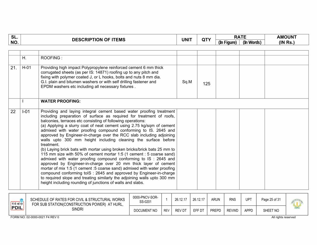
SL.NO. DESCRIPTION OF ITEMS UNIT QTY RATE AMOUNT
(IN Rs.) (In Figure) (In Words)
31SCHEDULE OF RATES FOR CIVIL & STRUCTURAL WORKS FOR SUB STATION(CONSTRUCTION POWER) AT HURL,
SINDRI
0000-PNCV-SOR-SS-0201 1 26.12.17 26.12.17 ARUN RNS UPT Page 25 of 31
DOCUMENT NO REV REV DT EFF DT PREPD REVWD APPD SHEET NO FORM NO: 02-0000-0021 F4 REV 0 All rights reserved
H. ROOFING :
21.
H-01
Providing high impact Polypropylene reinforced cement 6 mm thick corrugated sheets (as per IS: 14871) roofing up to any pitch and fixing with polymer coated J, or L hooks, bolts and nuts 8 mm dia. G.I. plain and bitumen washers or with self drilling fastener and EPDM washers etc including all necessary fixtures .
Sq.M
125
I WATER PROOFING:
22 I-01 Providing and laying integral cement based water proofing treatment including preparation of surface as required for treatment of roofs, balconies, terraces etc consisting of following operations: (a) Applying a slurry coat of neat cement using 2.75 kg/sqm of cement admixed with water proofing compound conforming to IS. 2645 and approved by Engineer-in-charge over the RCC slab including adjoining walls upto 300 mm height including cleaning the surface before treatment.(b) Laying brick bats with mortar using broken bricks/brick bats 25 mm to 115 mm size with 50% of cement mortar 1:5 (1 cement : 5 coarse sand) admixed with water proofing compound conforming to IS : 2645 and approved by Engineer-in-charge over 20 mm thick layer of cement mortar of mix 1:5 (1 cement :5 coarse sand) admixed with water proofing compound conforming toIS : 2645 and approved by Engineer-in-charge to required slope and treating similarly the adjoining walls upto 300 mm height including rounding of junctions of walls and slabs.

SL.NO. DESCRIPTION OF ITEMS UNIT QTY RATE AMOUNT
(IN Rs.) (In Figure) (In Words)
31SCHEDULE OF RATES FOR CIVIL & STRUCTURAL WORKS FOR SUB STATION(CONSTRUCTION POWER) AT HURL,
SINDRI
0000-PNCV-SOR-SS-0201 1 26.12.17 26.12.17 ARUN RNS UPT Page 26 of 31
DOCUMENT NO REV REV DT EFF DT PREPD REVWD APPD SHEET NO FORM NO: 02-0000-0021 F4 REV 0 All rights reserved
(c) After two days of proper curing applying a second coat of cement slurry using 2.75 kg/ sqm of cement admixed with water proofing compound conforming to IS : 2645 and approved by Engineerin-charge.
(d) Finishing the surface with 20 mm thick jointless cement mortar of mix 1:4 (1 cement :4 coarse sand) admixed with water proofing compound conforming to IS : 2645 and approved by Engineerin- charge including laying glass fibre cloth of approved quality in top layer of plaster and finally finishing the surface with trowel with neat cement slurry and making pattern of 300x300 mm square 3 mm deep.
(e) The whole terrace so finished shall be flooded with water for a minimum period of two weeks for curing and for final test. All above operations to be done in order and as directed and specified by the Engineer-in-Charge :
a With average thickness of 120 mm and minimum thickness at khurra as 65 mm.
Sqm 200
J FLOORS AND BASES :
23. J-01 Supplying and laying hard core under floors including watering, ramming, blinding and well consolidating with broken stone aggregates 90 mm to 40 mm in layers of maximum compacted thickness of 100 mm including filling the voids with smaller stone chips and with blinding materials fine river sand. (Payment shall be made for finished thickness of hard core) :
a. Consolidation by hand/ mechanical rammers Cu.M 200
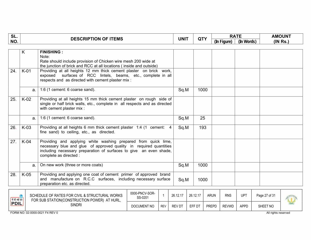
SL.NO. DESCRIPTION OF ITEMS UNIT QTY RATE AMOUNT
(IN Rs.) (In Figure) (In Words)
31SCHEDULE OF RATES FOR CIVIL & STRUCTURAL WORKS FOR SUB STATION(CONSTRUCTION POWER) AT HURL,
SINDRI
0000-PNCV-SOR-SS-0201 1 26.12.17 26.12.17 ARUN RNS UPT Page 27 of 31
DOCUMENT NO REV REV DT EFF DT PREPD REVWD APPD SHEET NO FORM NO: 02-0000-0021 F4 REV 0 All rights reserved
K FINISHING : Note:Rate should include provision of Chicken wire mesh 200 wide at the junction of brick and RCC at all locations ( inside and outside)
24. K-01 Providing at all heights 12 mm thick cement plaster on brick work, exposed surfaces of RCC lintels, beams, etc., complete in all respects and as directed with cement plaster mix :
a. 1:6 (1 cement: 6 coarse sand). Sq.M 1000
25. K-02 Providing at all heights 15 mm thick cement plaster on rough side of single or half brick walls, etc., complete in all respects and as directed with cement plaster mix :
a. 1:6 (1 cement: 6 coarse sand). Sq.M 25
26. K-03 Providing at all heights 6 mm thick cement plaster 1:4 (1 cement: 4 fine sand) to ceiling, etc., as directed.
Sq.M 193
27. K-04 Providing and applying white washing prepared from quick lime, necessary blue and glue of approved quality in required quantities including necessary preparation of surfaces to give an even shade, complete as directed :
a. On new work (three or more coats) Sq.M 1000
28. K-05 Providing and applying one coat of cement primer of approved brand and manufacture on R.C.C surfaces, including necessary surface preparation etc. as directed.
Sq.M 1000
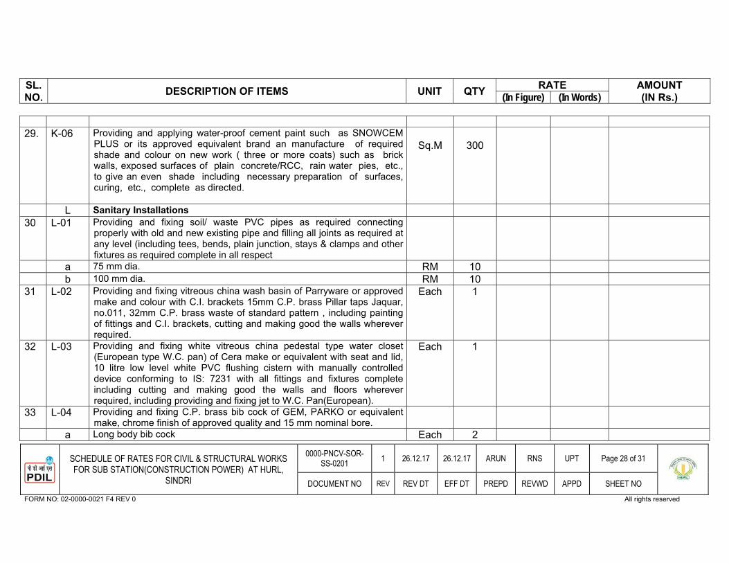
SL.NO. DESCRIPTION OF ITEMS UNIT QTY RATE AMOUNT
(IN Rs.) (In Figure) (In Words)
31SCHEDULE OF RATES FOR CIVIL & STRUCTURAL WORKS FOR SUB STATION(CONSTRUCTION POWER) AT HURL,
SINDRI
0000-PNCV-SOR-SS-0201 1 26.12.17 26.12.17 ARUN RNS UPT Page 28 of 31
DOCUMENT NO REV REV DT EFF DT PREPD REVWD APPD SHEET NO FORM NO: 02-0000-0021 F4 REV 0 All rights reserved
29. K-06 Providing and applying water-proof cement paint such as SNOWCEM PLUS or its approved equivalent brand an manufacture of required shade and colour on new work ( three or more coats) such as brick walls, exposed surfaces of plain concrete/RCC, rain water pies, etc., to give an even shade including necessary preparation of surfaces, curing, etc., complete as directed.
Sq.M 300
L Sanitary Installations 30 L-01 Providing and fixing soil/ waste PVC pipes as required connecting
properly with old and new existing pipe and filling all joints as required at any level (including tees, bends, plain junction, stays & clamps and other fixtures as required complete in all respect
a 75 mm dia. RM 10 b 100 mm dia. RM 10 31 L-02 Providing and fixing vitreous china wash basin of Parryware or approved
make and colour with C.I. brackets 15mm C.P. brass Pillar taps Jaquar, no.011, 32mm C.P. brass waste of standard pattern , including painting of fittings and C.I. brackets, cutting and making good the walls wherever required.
Each 1
32 L-03 Providing and fixing white vitreous china pedestal type water closet (European type W.C. pan) of Cera make or equivalent with seat and lid, 10 litre low level white PVC flushing cistern with manually controlled device conforming to IS: 7231 with all fittings and fixtures complete including cutting and making good the walls and floors wherever required, including providing and fixing jet to W.C. Pan(European).
Each 1
33 L-04 Providing and fixing C.P. brass bib cock of GEM, PARKO or equivalent make, chrome finish of approved quality and 15 mm nominal bore.
a Long body bib cock Each 2
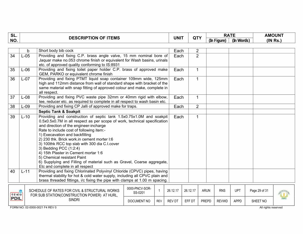
SL.NO. DESCRIPTION OF ITEMS UNIT QTY RATE AMOUNT
(IN Rs.) (In Figure) (In Words)
31SCHEDULE OF RATES FOR CIVIL & STRUCTURAL WORKS FOR SUB STATION(CONSTRUCTION POWER) AT HURL,
SINDRI
0000-PNCV-SOR-SS-0201 1 26.12.17 26.12.17 ARUN RNS UPT Page 29 of 31
DOCUMENT NO REV REV DT EFF DT PREPD REVWD APPD SHEET NO FORM NO: 02-0000-0021 F4 REV 0 All rights reserved
b Short body bib cock Each 2 34 L-05 Providing and fixing C.P. brass angle valve, 15 mm nominal bore of
Jaquar make no.053 chrome finish or equivalent for Wash basins, urinals etc. of approved quality conforming to IS:8931
Each 2
35 L-06 Providing and fixing toilet paper holder C.P. brass of approved make GEM, PARKO or equivalent chrome finish
Each 1
36 L-07 Providing and fixing PTMT liquid soap container 109mm wide, 125mm high and 112mm distance from wall of standard shape with bracket of the same material with snap fitting of approved colour and make, complete in all respect.
Each 1
37 L-08 Providing and fixing PVC waste pipe 32mm or 40mm rigid with elbow, tee, reducer etc. as required to complete in all respect to wash basin etc.
Each 1
38 L-09 Providing and fixing CP Jalli of approved make for traps. Each 2 Septic Tank & Soakpit
39 L-10 Providing and construction of septic tank 1.5x0.75x1.0M and soakpit 0.5x0.5x0.7M in all respect as per scope of work, technical specification and direction of the engineer-incharge Rate to include cost of following item:- 1) Execavation and backfilling 2) 230 thk. Brick work.in cement morter I:6 3) 100thk RCC top slab with 300 dia C.I.cover 3) Bedding PCC (1:2:4) 4) 15th Plaster in Cement mortar 1:65) Chemical resistant Paint 6) Supplying and Filling of material such as Gravel, Coarse aggregate, Etc and complete in all respect
Each 1
40 L-11 Providing and fixing Chlorinated Polyvinyl Chloride (CPVC) pipes, having thermal stability for hot & cold water supply, including all CPVC plain and brass threaded fittings, i/c fixing the pipe with clamps at 1.00 m spacing.
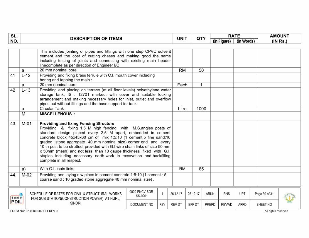
SL.NO. DESCRIPTION OF ITEMS UNIT QTY RATE AMOUNT
(IN Rs.) (In Figure) (In Words)
31SCHEDULE OF RATES FOR CIVIL & STRUCTURAL WORKS FOR SUB STATION(CONSTRUCTION POWER) AT HURL,
SINDRI
0000-PNCV-SOR-SS-0201 1 26.12.17 26.12.17 ARUN RNS UPT Page 30 of 31
DOCUMENT NO REV REV DT EFF DT PREPD REVWD APPD SHEET NO FORM NO: 02-0000-0021 F4 REV 0 All rights reserved
This includes jointing of pipes and fittings with one step CPVC solvent cement and the cost of cutting chases and making good the same including testing of joints and connecting with existing main header linecomplete as per direction of Engineer I/C
a 20 mm nominal bore RM 50 41 L-12 Providing and fixing brass ferrule with C.I. mouth cover including
boring and tapping the main :
a 20 mm nominal bore Each 1 42 L-13 Providing and placing on terrace (at all floor levels) polyethylene water
storage tank, IS : 12701 marked, with cover and suitable locking arrangement and making necessary holes for inlet, outlet and overflow pipes but without fittings and the base support for tank.
a Circular Tank Litre 1000 M MISCELLENOUS :
43. M-01 Providing and fixing Fencing Structure Providing & fixing 1.5 M high fencing with M.S.angles posts of standard design placed every 2.5 M apart, embedded in cement concrete block 45x45x60 cm of mix 1:5:10 (1 cement:5 fine sand:10 graded stone aggregate 40 mm nominal size) corner end and every 10 th post to be strutted, provided with G.I.wire chain links of size 50 mm x 50mm (mesh) and not less than 10 gauge thickness fixed with G.I. staples including necessary earth work in excavation and backfilling complete in all respect.
a) With G.I chain links RM 65 44. M-02 Providing and laying s.w pipes in cement concrete 1:5:10 (1 cement : 5
coarse sand : 10 graded stone aggregate 40 mm nominal size) .

SL.NO. DESCRIPTION OF ITEMS UNIT QTY RATE AMOUNT
(IN Rs.) (In Figure) (In Words)
31SCHEDULE OF RATES FOR CIVIL & STRUCTURAL WORKS FOR SUB STATION(CONSTRUCTION POWER) AT HURL,
SINDRI
0000-PNCV-SOR-SS-0201 1 26.12.17 26.12.17 ARUN RNS UPT Page 31 of 31
DOCUMENT NO REV REV DT EFF DT PREPD REVWD APPD SHEET NO FORM NO: 02-0000-0021 F4 REV 0 All rights reserved
a. 150 mm diameter S.W. pipe RM 35 45. M-03 Providing and fixing rolling shutters of approved make made of 80 mm
wide MS laths and interlocked together through their entire length and jointed together at the ends by end locks, mounted on specially designed pipe shaft with bracket plates, guide channels and arrangement for inside and outside locking with push-pull operation complete including cost of wire spring and hood cover for the shutters, (Measurement shall be done on the opening only).
Sq.m 15
46. M-04 Providing & Laying of Pebbles (20mm to 50mm) round in shape of good quality, free form organic material sulphates or any deleterious material.
Cum 20
47 M-05 Surface preparation of structural steel surfaces by power driven wire brush. (Rate to be quoted on tonnage of finished structural steel work).
Te 6
TOTAL OF PART-C (Without GST) : Rs.
Total Amount (Without GST) : (in Words) ______________________________________________________________________
GST Extra as applicable : (in Figures) _________ / (in Words) __________________________________________________
Total Amount (With GST) : (in Words) ______________________________________________________________________
Name of Tenderer :
Signature & Seal of Tenderer :
Place :
Date :
PART-D : SCHEDULE OF RATES FOR PRE-PROJECT ELECTRICAL WORKS
(O&M OF CONTRUCTION POWER & ELCTRICAL FACILITIES) AT HURL, SINDRI
5002-7411-0990 4 04.01.18 04.01.18 KS RKV RKV 1 OF 2
DOCUMENT NO. REV. REV. DT. EFF. DT. PREPD. REVWD. APPD. SHEET NO.
FORM NO: 02-0000-0021 F4 REV 2 All rights reserved
PART-D
SCHEDULE OF RATES
FOR
PRE-PROJECT ELECTRICAL WORKS
(OPERATION & MAINTENANCE OF CONSTRUCTION
POWER AND ELECTRICAL FACILITIES)
AT
HURL, SINDRI
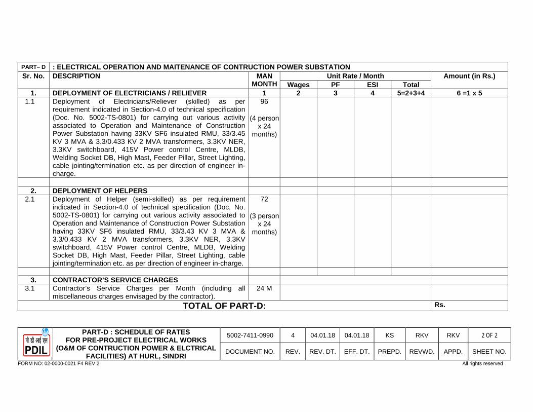
PART-D : SCHEDULE OF RATES FOR PRE-PROJECT ELECTRICAL WORKS
(O&M OF CONTRUCTION POWER & ELCTRICAL FACILITIES) AT HURL, SINDRI
5002-7411-0990 4 04.01.18 04.01.18 KS RKV RKV 2 OF 2
DOCUMENT NO. REV. REV. DT. EFF. DT. PREPD. REVWD. APPD. SHEET NO.
FORM NO: 02-0000-0021 F4 REV 2 All rights reserved
PART– D : ELECTRICAL OPERATION AND MAITENANCE OF CONTRUCTION POWER SUBSTATION Sr. No. DESCRIPTION MAN
MONTHUnit Rate / Month Amount (in Rs.)
Wages PF ESI Total 1. DEPLOYMENT OF ELECTRICIANS / RELIEVER 1 2 3 4 5=2+3+4 6 =1 x 5
1.1 Deployment of Electricians/Reliever (skilled) as per requirement indicated in Section-4.0 of technical specification (Doc. No. 5002-TS-0801) for carrying out various activity associated to Operation and Maintenance of Construction Power Substation having 33KV SF6 insulated RMU, 33/3.45 KV 3 MVA & 3.3/0.433 KV 2 MVA transformers, 3.3KV NER, 3.3KV switchboard, 415V Power control Centre, MLDB, Welding Socket DB, High Mast, Feeder Pillar, Street Lighting, cable jointing/termination etc. as per direction of engineer in-charge.
96
(4 person x 24
months)
2. DEPLOYMENT OF HELPERS
2.1 Deployment of Helper (semi-skilled) as per requirement indicated in Section-4.0 of technical specification (Doc. No. 5002-TS-0801) for carrying out various activity associated to Operation and Maintenance of Construction Power Substation having 33KV SF6 insulated RMU, 33/3.43 KV 3 MVA & 3.3/0.433 KV 2 MVA transformers, 3.3KV NER, 3.3KV switchboard, 415V Power control Centre, MLDB, Welding Socket DB, High Mast, Feeder Pillar, Street Lighting, cable jointing/termination etc. as per direction of engineer in-charge.
72
(3 person x 24
months)
3. CONTRACTOR’S SERVICE CHARGES
3.1 Contractor’s Service Charges per Month (including all miscellaneous charges envisaged by the contractor).
24 M
TOTAL OF PART-D: Rs.
PROJECTS & DEVELOPMENT INDIA LIMITED
PNCN-HSE-01 0
DOC. NO. REVPage 1 of 38
FORM NO: 02-0000-0021F1 REV4
PART-IV
HEALTH, SAFETY AND ENVIRONMENT (HSE) MANAGEMENT
0 30.10.17 30.10.17 FOR ISSUANCE DILIP GC SM REV REV DATE EFF DATE PURPOSE PREPD REVWD APPD
HEALTH, SAFETY & ENVIRONMENT (HSE) MANAGEMENT
PNCN-HSE-01 0
DOC. NO. REV. Page 2 of 38
_________________________________________________________________________________________________________ FORM NO 02-0000-0021 F2 REV 3
TABLE OF CONTENTS
1.0 INTRODUCTION .......................................................................................................................................................................... 2.0 GENERAL ..................................................................................................................................................................................... 3.0 SITE HEALTH, SAFETY AND ENVIRONMENT INDUCTION .................................................................................................... 4.0 DEMARCATION ........................................................................................................................................................................... 5.0 ACCESS TO THE CLIENT’S FACILITIES/BUILDINGS .............................................................................................................. 6.0 BEHAVIOR ON SITE ................................................................................................................................................................... 7.0 SMOKING, EATING AND DRINKING ......................................................................................................................................... 8.0 DRUGS AND ALCOHOL .............................................................................................................................................................. 9.0 PERMIT TO WORK SYSTEM ...................................................................................................................................................... 10.0 ACCESS, SITE PASSES AND SECURITY ................................................................................................................................. 11.0 PARKING, DELIVERIES AND VEHICLE PASSES ..................................................................................................................... 12.0 SITE OPENING AND CLOSING TIMES ..................................................................................................................................... 13.0 SITE SUPERVISION .................................................................................................................................................................... 14.0 TRAINING, COMPETENCE OF EMPLOYEES AND NOTIFICATION OF HAZARDS ............................................................... 15.0 METHOD STATEMENTS ............................................................................................................................................................. 16.0 RISK ASSESSMENTS ................................................................................................................................................................. 17.0 COMPLIANCE WITH STATUTORY REGULATIONS ................................................................................................................. 18.0 INFORMATION TO BE PROVIDED AND POSTED ................................................................................................................... 19.0 PERSONAL PROTECTIVE EQUIPMENT/CLOTHING ............................................................................................................... 20.0 SUBSTANCES (Control of Substances Hazardous to Health – COSHH) .................................................................................. 21.0 NOISE ........................................................................................................................................................................................... 22.0 FIRST AID .................................................................................................................................................................................... 23.0 TOOL BOX TALKS ....................................................................................................................................................................... 24.0 HEALTH, SAFETY AND ENVIRONMENT INSPECTIONS/HEALTH, SAFETY AND ENVIRONMENT ADVISORS ................ 25.0 HEALTH, SAFETY AND ENVIRONMENT MEETINGS .............................................................................................................. 26.0 HEALTH, SAFETY AND ENVIRONMENT COMMITTEES AND SAFETY REPRESENTATIVES ............................................ 27.0 HOUSEKEEPING ......................................................................................................................................................................... 28.0 FIRE PREVENTION ..................................................................................................................................................................... 29.0 REMOVAL OF WASTE FROM CONSTRUCTION SITES ...................................................................................................... 15 30.0 EXCAVATIONS AND OPENINGS ............................................................................................................................................... 31.0 ELECTRICITY .............................................................................................................................................................................. 32.0 WORK IN CONFINED SPACES .................................................................................................................................................. 33.0 MOBILE CRANES ........................................................................................................................................................................ 34.0 LIFTING OPERATIONS ............................................................................................................................................................... 35.0 STEEL ERECTION ...................................................................................................................................................................... 36.0 SCAFFOLDING ............................................................................................................................................................................ 37.0 LADDERS/STEPS ........................................................................................................................................................................ 38.0 FALL PROTECTION .................................................................................................................................................................... 39.0 MOBILE ELEVATED WORK PLATFORMS ................................................................................................................................ 40.0 CONTRACTORS’ TOOLS AND EQUIPMENT ............................................................................................................................ 41.0 MECHANICAL PLANT AND EQUIPMENT .................................................................................................................................. 42.0 COMPETENCY/PLANT EQUIPMENT .........................................................................................................................................
HEALTH, SAFETY & ENVIRONMENT (HSE) MANAGEMENT
PNCN-HSE-01 0
DOC. NO. REV. Page 3 of 38
_________________________________________________________________________________________________________ FORM NO 02-0000-0021 F2 REV 3
43.0 MACHINERY GUARDING ........................................................................................................................................................... 44.0 WELDING ..................................................................................................................................................................................... 45.0 ABRASIVE WHEELS ............................................................................................................................................................... 28 46.0 USE OF GAS AND OXYGEN EQUIPMENT ............................................................................................................................... 47.0 ABRASIVE AIR BLAST CLEANIN ............................................................................................................................................... 48.0 COMPRESSED AIR ..................................................................................................................................................................... 49.0 MOBILE PHONES AND PAGERS ............................................................................................................................................... 50.0 RADIOGRAPHY/NDT .................................................................................................................................................................. 51.0 WORKING OVER WATER/DIVING OPERATIONS .................................................................................................................... 52.0 ASBESTOS .................................................................................................................................................................................. 53.0 IMPROVEMENT AND PROHIBITION NOTICES ........................................................................................................................ 54.0 CARTRIDGE OPERATED FIXING TOOLS ................................................................................................................................. 55.0 SITE ESTABLISHMENT AND AMENITIES ................................................................................................................................. 56.0 ACCOMMODATION ..................................................................................................................................................................... 57.0 TEMPORARY SERVICES ........................................................................................................................................................... 58.0 DISCHARGES INTO THE INTERNAL AND EXTERNAL DRAINAGE SYSTEMS, LAND AND CONSTRUCTION AREAS .... 59.0 MAINTENANCE OF ROADS AND DRAINS ................................................................................................................................ 60.0 MATERIALS – STORAGE AND CONTROL ................................................................................................................................ 61.0 PENALTY 62.0 FOLLOWING SHALL BE APPLICABLE FOR MANDATORY MEDICAL EXAMINATION OF CONTRACTOR WORKERS BEFORE DEPLOYMENT AT WORK SITE: 63.0 ADDITIONAL SAFETY REQUIREMENT .....................................................................................................................................
HEALTH, SAFETY & ENVIRONMENT (HSE) MANAGEMENT
PNCN-HSE-01 0
DOC. NO. REV. Page 4 of 38
_________________________________________________________________________________________________________ FORM NO 02-0000-0021 F2 REV 3
1.0 INTRODUCTION 1.1 The purpose of the present document is to outline the minimum safety requirements
applicable to personnel, equipment and facilities during erection, pre-commissioning and
commissioning activities of OWNER / CONSULTANT Construction Sites. Constructing safe
structure and providing safe working environment to the personnel is a vital factor in
successful construction business. Safety and health are as much as part of effective project
planning and control as the cost, schedules, procurement and quality. Indeed they are all
closely interrelated. Productivity, safety and quality can move forward in close proximity.
1.2 OBJECTIVES OWNER/CONSULTANT Site Management has following main objectives regarding safety
at site. a) No Accident b) To make the environment safe c) No harm to people d) Safety is everyone’s responsibility e) To make the job safe 2.0 GENERAL 2.1 These rules do not exempt the Contractor from statutory Health, Safety and Environmental
duties but are intended to assist in attaining a high standard of compliance with those duties, in order to provide a safe and healthy working environment.
2.2 OWNER/CONSULTANT will assist Contractors in any practical way to facilitate safe
working, and requires full co-operation in observing these rules. 2.3 The rules for Health and Safety specified herein are in no way intended to relieve the
Contractor from any obligation or liability under the Contract, nor is it intended to relieve the Contractor of any of his legal obligations for the avoidance of accidents.
2.4 In all matters arising in the performance of the Contract, the Contractor shall conform with all
Statutory Regulations and By-Laws made with statutory authority by Government Departments or by Local or other Authorities that shall be applicable to the Works.
2.5 The Contractor, in the performance of the Contract, shall not endanger the safety or
unlawfully interfere with the convenience of the public in any manner. 2.6 The Contractor's representative on Site shall communicate details of these rules for Health,
Safety and Environment to all Contractors’ employees and to all Subcontractors and Subcontractors’ employees employed on the Site.
HEALTH, SAFETY & ENVIRONMENT (HSE) MANAGEMENT
PNCN-HSE-01 0
DOC. NO. REV. Page 5 of 38
_________________________________________________________________________________________________________ FORM NO 02-0000-0021 F2 REV 3
2.7 The requirements of the Client/Owner's existing Site Rules/Regulations form part of the
Contract and in the case of conflict between the OWNER/CONSULTANT’S rules, the highest standard shall be applied.
2.8 At the tender stage OWNER/CONSULTANT will require to see a copy of the Contractor's
policy, organization and arrangements for the Health and Safety at Work. The Contractor shall submitted complete documents Health and Safety Questionnaire. Contractor shall deploy safety officer of adequate experience at each work site or during each shift including Sunday/holiday with approval of EIC/Owner.
3.0 SITE HEALTH, SAFETY AND ENVIRONMENT INDUCTION 3.1 All personnel shall receive OWNER/CONSULTANT and Contractors’ site Health, Safety and
Environment induction before they commence work on site. The induction shall comprise information on the various hazards which they may come into contact with, instructions on the site emergency procedures, warning and alarm systems, and permit to work system, first aid locations, welfare facilities, access routes and project specific rules.
3.2 It is the responsibility of the Contractor to familiarize all new personnel to the Project on the
actual location of muster points, fire alarm points, first aid stations and the like. 4.0 DEMARCATION 4.1 Construction personnel are restricted to the construction areas shown on the Contract
Drawings. Any personnel found on/in or interfering with the existing works/plant, without permission, will be dismissed from site. Any work outside of these areas may only be carried out with the written agreement of OWNER/CONSULTANT.
Before any work is started on the site, the Contractor's representative shall report to
OWNER/CONSULTANT, who will confirm to the Contractor's representative, the limits of the working area(s) and shall be informed of any special requirements appertaining thereto.
5.0 ACCESS TO THE CLIENT’S FACILITIES/BUILDINGS 5.1 The Client’s Facilities, including the canteen/cafeteria and toilets shall not be used by
Construction Personnel. 5.2 Construction Personnel shall not enter any of the Owner’s building unless escorted by a
member of the OWNER/CONSULTANT’S staff (or working with prior agreement to Owner’s Permit to Work System).
6.0 BEHAVIOR ON SITE 6.1 All Contractors' personnel shall treat everyone with respect and will refrain from any sexually
suggestive or abusive comments or behavior. 7.0 SMOKING, EATING AND DRINKING
HEALTH, SAFETY & ENVIRONMENT (HSE) MANAGEMENT
PNCN-HSE-01 0
DOC. NO. REV. Page 6 of 38
_________________________________________________________________________________________________________ FORM NO 02-0000-0021 F2 REV 3
7.1 Smoking, eating and drinking is allowed in designated areas. 8.0 DRUGS AND ALCOHOL 8.1 The possession or use of illicit drugs and alcohol on site is not permitted. Anyone who is
found, or suspected to be, under the influence of either will be removed from site (subject to the Contractors’ disciplinary procedure).
8.2 Anyone taking prescriptive drugs shall advise their employer, in particular those drugs that
may impair their performance. Their employer may make arrangements to assign them to more suitable work, but shall ensure that the OWNER/CONSULTANT Construction manager is informed without delay.
9.0 PERMIT TO WORK SYSTEM 9.1 All construction works will be carried out under a permit to work system. It is designed to
protect personnel and plant and consists of an organized and predefined safety procedure. It forms a clear record of all foreseeable hazards which have been considered in advance of construction operations.
9.2 The identities of the permit “Issuing Authority” will be OWNER and the “Permit Acceptor” will
be the Contractor. 9.3 The following types of permits will be issued: • Clearance Certificate - all other permits are invalid without this Certificate, (this
certificate can be used for general work). • Hot Job Work Permit. • Electrical Work Permit. • Confined Spaces Work Permit. • Excavations Work Permit. • Working at Height work Permit. • Radiography Work Permit. • Cold Job Work Permit. • Road Closure Work Permit. 9.4 Written requests for permits must be submitted to Owner at least twenty-four hours in
advance and the permits will be issued daily. Permits shall be given to Safety Officers of the contractor, by representatives authorized by Owner in approved formats.
10.0 ACCESS, SITE PASSES AND SECURITY 10. 1 Passes All personnel and vehicles shall enter and leave the site via the entrance authorized for
construction personnel and traffic. Contractors' employees shall not enter any part of the site other than for the purpose of carrying out the Works.
All personnel shall be issued with a site pass. The site pass must be carried (or displayed
on the pass holder's lapel) at all times. Details of all personnel requiring site passes shall be submitted to OWNER/CONSULTANT at least seven working days in advance of the
HEALTH, SAFETY & ENVIRONMENT (HSE) MANAGEMENT
PNCN-HSE-01 0
DOC. NO. REV. Page 7 of 38
_________________________________________________________________________________________________________ FORM NO 02-0000-0021 F2 REV 3
planned start-on-site date. Site passes shall be submitted for inspection on entering or
leaving the site, or when requested for inspection by OWNER/CONSULTANT or Security. Loss of site passes must be reported immediately to Owner/Consultant. Lack of a site pass
may mean delay at the site entrance. Owner/Consultant shall not accept any responsibility for lost time or costs incurred.
On completion of their assignment, or termination or their employment, all personnel will
return their site pass to Owner or Owner representative/ Owner authorized personal. 10.2 Security The security of Contractor's plant, tools, equipment, materials (including free issue materials
properly handed-over by Owner/Consultant) are the responsibility of the Contractor. It is the Contractor's responsibility to satisfy themselves that the security arrangements in existence on the site are adequate. The Contractor shall provide any other security measure that he deems necessary for the control and security of Contractor owned equipment and plant, including for free-issue plant and materials, both within the site establishment area and the working areas on the site.
Owner accepts no liability for any loss, damage or deterioration to the Contractor's plant
tools equipment and materials. Owner reserves the right to search at random all personnel, any Contractor's employee, or
employees of its servants, agents, Contractors or any vehicle entering or leaving the site. Any package or container being taken into or out of the site may be opened and inspected by security staff or any other persons authorized by Owner/Consultant to make such a search or inspection.
It is the Contractor's obligation and responsibility to ensure that OWNER / CONSULTANT
right to search and inspect persons and property, extends to and is brought to the attention of all his personnel.
Personnel shall give all possible assistance and make available any facilities required to
assist OWNER/CONSULTANT and the Police in pursuance of the prosecution of any person(s) responsible for alleged malicious damage or loss to the Works or existing installations.
Owner shall not accept any responsibility for the loss or damage of personal effects. The
security and safekeeping of personal effects is the responsibility of each individual. 10.3 Construction personnel will not be admitted to the Construction Areas unless they have
undergone Owner/ Consultant’s induction, and received a security pass. No Induction, No Pass, No Access to the Site 10.4 OWNER/CONSULTANT reserves the right to deny access to the Construction Site/Areas
and/or the Construction Car parks to any person, or vehicle.
HEALTH, SAFETY & ENVIRONMENT (HSE) MANAGEMENT
PNCN-HSE-01 0
DOC. NO. REV. Page 8 of 38
_________________________________________________________________________________________________________ FORM NO 02-0000-0021 F2 REV 3
10.5 Individuals may be excluded from and refused future entry to the Site and/or Construction
Areas for any breach of Safety or Security Rules, or exceeding the speed limit (20 mph on roads leading to the site off the public highway and 5 mph in the construction area).
10.6 No plant/skips waste or materials may leave the Construction Area without the clearance of
OWNER/CONSULTANT. 10.7 The taking of photographs on the site is prohibited. 10.8 Vehicles with children under the age of 16 years or animals onboard will not be allowed
access. 10.9 Visitors will only be allowed by appointment (two days’ notice to OWNER/CONSULTANT is
required). Visitors shall be accompanied by a member of the Contractor’s team (who has received Health, Safety and Environment Induction) at all times. The visitor will have to obtain a visitor’s pass, and be collected from and returned to the main gate.
10.10 Each Contractor will keep a daily register of who is on site. The register will record name,
pass number, time-in and time-out (records on time-clocks will not be permitted). This information shall be used to check personnel (role call) in the event of an emergency
11.0 PARKING, DELIVERIES AND VEHICLE PASSES 11.1 Contractors’ personnel shall not be allowed to park any vehicle on the main car park or site.
All contractors shall park in the Contractors’ Temporary Car Park. 11.2 The Contractor shall arrange transport between the parking area(s), the main site gate and
the Contractor's establishment and working areas if judged to be necessary. 11.3 Vehicles used solely for transporting of tools and equipment may be allowed access to the
working area(s) for unloading/loading only. 11.4 Owners of vehicles parked illegally will have their car pass taken off them and told to
remove the vehicle from site. They may have their site pass withdrawn and be refused further access to the Construction Site.
11.5 The Construction Areas will be restricted to construction plant and delivery vehicles. 11.6 The speed limit on site is 10 mph on the approach roads leading to the site off the public
highway and 5 mph on the construction areas 12.0 SITE OPENING AND CLOSING TIMES 12.1 The site will be open from 8.00am to 6.00pm Monday to Saturday. Work outside the agreed
normal working hours will be by agreement with Owner (subject to two working days’ notice). All applications for out of hour working will identify the scope of work, supervision arrangements and a list of personnel.
HEALTH, SAFETY & ENVIRONMENT (HSE) MANAGEMENT
PNCN-HSE-01 0
DOC. NO. REV. Page 9 of 38
_________________________________________________________________________________________________________ FORM NO 02-0000-0021 F2 REV 3
13.0 SITE SUPERVISION 13.1 The Contractor must ensure that an employee of suitable seniority and authority, with
responsibility for Health and Safety, is always present on site during the course of the works, to supervise and direct the Works and to receive and implement instructions from OWNER/CONSULTANT. Seven days before commencing works on site, the Contractor must notify OWNER/CONSULTANT of the name of that employee.
13.2 All supervisory staff shall be made aware of their responsibilities for safety. 14.0 TRAINING, COMPETENCE OF EMPLOYEES AND NOTIFICATION OF HAZARDS 14.1 Each Contractor must ensure that all his supervision and employees have had adequate
safety training and are experienced to carry out their work safely, prior to starting on site. Training should be continuous throughout a project and should include regular toolbox discussions, (on site briefings at the start of each working day/shift).
To this end, the Contractor must also ensure that specific hazards likely to be experienced
on the Site, whether notified to them or discovered by them, are notified to their workforce together with any precautions to be taken and local rules to be observed. Similarly, such hazards should be notified to their Subcontractors and, where discovered by them, to OWNER/CONSULTANT.
14.2 Where particularly severe or unusual hazards may arise on site, OWNER/CONSULTANT
reserves the right at no additional cost to request Contractors’ employees to attend special safety training and instruction sessions, whether carried out on site or externally. OWNER/CONSULTANT also requires Contractors’ employees to undergo specified induction safety training. These aspects should be checked prior to submission of Tenders or execution of the works.
15.0 METHOD STATEMENTS 15.1 Contractors shall submit Safety Method Statements and JSA for all work activities, for
example: • Piling Operations. • Excavation works. • Lifting operations, as specified. • Steel erection. • Hot work operations. • Radiography/NDT. • Entry into confined spaces. • Pressure testing. • Working at height. • Shot fired tools. • Installation of pre-cast concrete planks. • Pre-cast concrete structure. • The erection of safety nets and fall arrest equipment.

HEALTH, SAFETY & ENVIRONMENT (HSE) MANAGEMENT
PNCN-HSE-01 0
DOC. NO. REV. Page 10 of 38
_________________________________________________________________________________________________________ FORM NO 02-0000-0021 F2 REV 3
Safety method statements must also be submitted for activities which have been identified
as being of significant risk during the risk assessment process and activities selected by OWNER/CONSULTANT.
15.2 All Safety method statements must be submitted to OWNER/CONSULTANT at least seven
days before planned commencement of the works. 15.3 The Safety method statement shall detail: • The job to be undertaken. • The individual activities required to complete the job. • The individual trades/disciplines involved in each activity. • Plant, equipment and tools be used in each activity. • Any substances/chemicals to be used and where, and during which activity they will be
used (together with a COSHH assessment). • The Name(s) of the Supervisor(s) for each activity. • The Name of the person in overall charge of the job. • A detailed description of how the work will be done including control measures and
procedures to complete each activity and the overall job safety. • All hot work. 15.4 Compliance with the contents of the safety method statement shall be monitored on a daily
basis and addressed during Contractors’ safety management meetings. 15.5 The Contractor must ensure that employees executing the works are fully briefed and are
made aware of the details within the approved Safety Method Statements, prior to starting the task, this includes highlighting hazards associated, associated risk assessments and reduction measures.
16.0 RISK ASSESSMENTS 16.1 Contractors will be required to produce risk assessments for all works under their control.
The risk assessment shall be submitted as part of the Safety Method Statement to OWNER/CONSULTANT at least seven days before the job commences, and include the following information:
• Identification of all hazards applicable to significant risk activities. • Details of measures in place to control the risk. • Justification that the existing control measures are adequate or if not, a detailed action
plan on how the risk(s) shall be controlled. 16.2 The use of Generic Risk Assessments is only acceptable if they follow the logical
progression of the method statement and that specific operation, otherwise, task specific risk assessments will be required.
16.3 All risk assessments must be communicated to the workforce who will be responsible for
undertaking the work.
HEALTH, SAFETY & ENVIRONMENT (HSE) MANAGEMENT
PNCN-HSE-01 0
DOC. NO. REV. Page 11 of 38
_________________________________________________________________________________________________________ FORM NO 02-0000-0021 F2 REV 3
17.0 COMPLIANCE WITH STATUTORY REGULATIONS 17.1 Contractors shall carry out their work in accordance with statutory legislation. It is the duty of the Contractor to have knowledge of all relevant legislation and take account
of it in the planning and execution of the work on OWNER/CONSULTANT’ Sites. 18.0 INFORMATION TO BE PROVIDED AND POSTED 18.1 Contractors shall have in place, and issue to OWNER/CONSULTANT the following
documents or information prior to commencement of their work, (where detailed within these rules):
18.1.1 Safety, Health and Environmental Policy. 18.1.2 Employer's Liability Insurance Certificate. 18.1.3 A detailed Health, Safety and Environment Plan, compliant with the project plan
developed by the Planning Supervisor and/or Principal Contractor. 18.1.4 Work Method Statement Lifting Studies. 18.1.5 COSHH Procedures and Assessments. 18.1.6 Noise Procedures and Assessments. 18.1.7 Name of the individual appointed as the Site Safety Supervisor/Advisor. 18.1.8 Test certificates and examination for lifting gear, plant and appliances to be used on
site. (Duplicates to be provided for OWNER/CONSULTANT’s records.) 18.1.9 Drawings and calculations relating to false work, designed scaffolds, ground works
and supporting temporary works. 18.1.10 Details of young persons to be employed on site. 18.1.11 Information relating to hazards associated with plant, operation and materials used
in the works. 18.1.12 Proof of training for all personnel engaged in the works. 18.1.13 Daily Labour Returns. 18.1.14 Monthly Return of Accident Statistics to submitted OWNER/CONSULTANT format
(Nil returns required). 18.1.15 Personal Injury Report to submitted to OWNER/CONSULTANT format (all injuries,
however minor, to be reported). OWNER/CONSULTANT may request a detailed investigation into an accident. OWNER/CONSULTANT’ decision on which incidents require detailed investigation is final.
18.1.16 Dangerous Occurrences, Incidents, Damage to Equipment and/or Property report to be submitted to OWNER/CONSULTANT format.
18.1.17 All entries/records of accidents entered into the Contractor's Accident Book shall also be copied into OWNER/CONSULTANT’ Accident Book by the Contractor.
18.1.18 Copies of all Statutory Registers to be submitted weekly to OWNER/CONSULTANT. 18.1.19 Copies of the Contractor's Safety Officer/Advisor's reports of their findings on site
visits/inspections. 18.2 Accidents, Incidents, Dangerous Occurrences and Notifiable Diseases 18.2.1 Accidents/Incidents/ Dangerous Occurrences/Near Misses All accidents/incidents/dangerous occurrences/near misses must be notified to
OWNER/CONSULTANT immediately, and a report prepared.
HEALTH, SAFETY & ENVIRONMENT (HSE) MANAGEMENT
PNCN-HSE-01 0
DOC. NO. REV. Page 12 of 38
_________________________________________________________________________________________________________ FORM NO 02-0000-0021 F2 REV 3
For reportable incidents, a copy the report to the Authority must be submitted to OWNER/CONSULTANT on completion but no later than two calendar days after the accident.
18.2.2 OWNER/CONSULTANT reserves the right to decide which accident, incidents or
minor injuries shall be Investigated, and to what extent/format/contents of any investigation.
Note: All such notification or reports to OWNER/CONSULTANT do not release the
Contractor of his statutory duties to report such matters to the Authorities by the quickest possible means (viz, telephone, fax and e-mail) immediately following the incident/accident.
19.0 PERSONAL PROTECTIVE EQUIPMENT/CLOTHING 19.1 All personnel on OWNER/CONSULTANT’ site must wear as a minimum safety helmet, hi-
vis vest, safety glasses and protective footwear. Additional personal protective equipment may be required dependent on the tasks being undertaken or as dictated by the risk assessment.
19.2 Contractors shall provide all necessary personal protective clothing and equipment for their
employees and renew as necessary. Records of the issue of such equipment must be maintained for inspection by OWNER/CONSULTANT.
19.3 The Contractor shall: • Provide personal protective equipment which is comfortable and fit for purpose. • Maintain and clean personal protective equipment. • Replace free of charge defective, broken or lost personal protective equipment. • Provide storage for personal protective equipment when not being used. • Ensure that personal protective equipment is properly used. • Give training, information and instruction on its use to employees. • Ensure that all personnel wear suitable clothing at all times (no shorts, no sports
shirts and no colours that may invite aggression - HSE “Keep Your Tops On” is enforced).
• OWNER/CONSULTANT reserves the right to direct the contractor to change/replace personal protective equipment if they determine that it is unsuitable or inadequate for its proposed use.
20.0 SUBSTANCES (Control of Substances Hazardous to Health – COSHH) 20.1 Substances hazardous to health must be identified prior to taking them onto site and, if they
cannot be substituted or eliminated, assessments stating how the substances will be controlled and what precautions will be introduced must be carried out and recorded in writing by a competent person. This assessment must be communicated to, and understood by, the members of the workforce who are likely to come into contact with the substance(s). A copy of all assessments should be submitted to OWNER/CONSULTANT.
20.2 Hazardous substances may only be brought to site with OWNER/CONSULTANT’
permission. They shall be kept to a minimum and must be stored in secure, appropriate containers with the contents clearly labelled. The containers must be stored in a secure
HEALTH, SAFETY & ENVIRONMENT (HSE) MANAGEMENT
PNCN-HSE-01 0
DOC. NO. REV. Page 13 of 38
_________________________________________________________________________________________________________ FORM NO 02-0000-0021 F2 REV 3
area, preferably quarantined from the main stores areas, with suitable warning notices and signage posted.
20.3 Hazardous materials must not be allowed to discharge into natural watercourses or
drainage systems. 20.4 All hazardous material waste must be kept separate from normal waste and be disposed of
in a specialist disposal facility. 21.0 NOISE 21.1 When any operation of a Contractor is likely to expose any employee on site to an average
noise level of 85 dB(A) and above, an assessment shall be carried out, by the Contractor, and records maintained for OWNER/CONSULTANT’ inspection. In such circumstances, the Contractor must keep stocks of adequate ear defenders or other suitable hearing protection.
21.2 In addition to the foregoing, noise must be kept to a minimum at all times and must not
exceed acceptable and/or locally specified rules and conditions relating to noise imposed by the Contract. Due regard must always be given to noise levels, and their effects on the local community and persons not involved in the operations. Permissible times for noisy work operations, and other restrictions, may be imposed by the Local Authority. Contractors receiving Notices or Prohibition Notices under the related legislation must notify OWNER/CONSULTANT of such Notices.
22.0 FIRST AID 22.1 All Contractors shall provide or ensure that they are provided with, such equipment and
facilities as are adequate and appropriate in the circumstances for enabling first-aid to be rendered to any of their employees if they are injured or become ill at work.
22.2 No work shall commence on site until Contractors have trained first aid personnel on site.
Contractor at all times during execution, shall station at site an emergency vehicle without any extra cost or claim.
23.0 TOOL BOX TALKS 23.1 Tool Box Talks will be implemented by all Contractors. The agenda for these talks will be
agreed with OWNER/CONSULTANT prior to the commencing of work. 24.0 HEALTH, SAFETY AND ENVIRONMENT INSPECTIONS/HEALTH, SAFETY AND
ENVIRONMENT ADVISORS 24.1 The OWNER/CONSULTANT’ Health, Safety and Environment Engineer/Advisor will visit the
sites and carry out Site Safety Inspections. Contractors must co-operate in these inspections. Whenever Contractors’ own Health, Safety and Environment Advisors visit site they must report their arrival and departure to the OWNER/CONSULTANT’ Senior Representative, and provide a report of their findings and any necessary corrective action to be undertaken.
HEALTH, SAFETY & ENVIRONMENT (HSE) MANAGEMENT
PNCN-HSE-01 0
DOC. NO. REV. Page 14 of 38
_________________________________________________________________________________________________________ FORM NO 02-0000-0021 F2 REV 3
24.2 Contractors on the project must provide a full-time site based Health, Safety and Environment Advisor, when the intensity of the work requires or at the request of the OWNER/CONSULTANT.
24.3 Contractors who do not have full-time site based Health, Safety and Environment Advisors,
shall ensure that their Health, Safety and Environment Advisor visits site once per week as a minimum.
24.4 Appointment of Health, Safety and Environment Supervision The Contractor shall appoint safety supervision. The name of each appointee, together with
evidence of his or her competence to carry out the requirements of the role, shall be submitted to OWNER/CONSULTANT for their approval.
25.0 HEALTH, SAFETY AND ENVIRONMENT MEETINGS 25.1 Health, Safety and Environment will form part of the agenda at all Site Progress Meetings.
The Contractor’s Safety Advisor may be asked to attend these progress meetings. 25.2 Once per month OWNER/CONSULTANT’ Resident Construction Manager shall convene a
Health Safety and Environment Meeting of all Contractors. Attendees at the meeting shall be all Contractors’ Safety Advisors and Site Managers.
26.0 HEALTH, SAFETY AND ENVIRONMENT COMMITTEES AND SAFETY
REPRESENTATIVES 26.1 OWNER/CONSULTANT encourages the workforce to nominate Safety Representatives as
a way of improving communication on Health, Safety and Environment issues. Wherever Contractors’ Safety Representatives have been appointed, OWNER/CONSULTANT must be informed of their appointment in writing.
27.0 HOUSEKEEPING 27.1 Contractors are expected to carry out their work in a clean, safe and orderly manner. 27.2 Dust shall be kept to acceptable levels for the work being carried out. Waste materials and
rubbish shall be cleared up as the work progresses and not left to introduce a safety hazard for other personnel engaged on the works.
27.3 Construction waste should never obstruct emergency exit routes, Firefighting equipment,
emergency alarm call points or other emergency facilities. 27.4 From time to time as judged necessary, at the expiration of the contract, or when instructed
to do so by OWNER/CONSULTANT, the Contractor shall undertake to clean and tidy his areas of occupation and work to the satisfaction of OWNER/CONSULTANT. Should the Contractor fail to do this, OWNER/CONSULTANT reserves the right to remove all offending materials and debris and to deduct the cost of this operation from the Contract Price. OWNER/CONSULTANT accepts no responsibility for any materials and/or tools which may be removed during this operation.
HEALTH, SAFETY & ENVIRONMENT (HSE) MANAGEMENT
PNCN-HSE-01 0
DOC. NO. REV. Page 15 of 38
_________________________________________________________________________________________________________ FORM NO 02-0000-0021 F2 REV 3
27.5 The Contractor must ensure that the following requirements are strictly enforced: • Ample provision of refuse bins for all rubbish including organic waste such as food
scraps, etc. • Daily clearance of all such bins to the area designated for this discharge. • No discharge of deleterious matter such as oils or other industrial waste. 27.6 All site offices, toilets, eating facilities, changing rooms, drying areas, stores, etc, which are
the responsibility of the Contractor, shall be cleaned daily as a minimum by the Contractor. These facilities shall be checked for vermin on a two weekly rota.
28.0 FIRE PREVENTION 28.1 Before welding, flame or arc cutting of metals, or other processes involving heat or naked
lights are permitted, a fire risk assessment shall be carried out by the contractor and arrangements agreed with OWNER/CONSULTANT who will issue a Permit to Work.
28.2 Contractors shall familiarize both themselves and their employees with the fire safety
arrangements, fire alarms, means of escape and emergency evacuation procedures. 28.3 Before leaving the premises and site, contractors shall ensure that naked lights and other
ignition sources have been extinguished and electrical apparatus, where practicable, switched off and/or disconnected.
28.4 Contractors shall store Highly Flammable Liquids and Liquefied Petroleum Gases in a
manner approved by OWNER/CONSULTANT. 28.5 OWNER/CONSULTANT’ fire protection equipment shall only be used in an Emergency.
Fire extinguishers/fire blankets for use when carrying out hot work shall be provided by the Contractor.
29.0 REMOVAL OF WASTE FROM CONSTRUCTION SITES 29.1 The removal of waste shall only be undertaken by Licensed Waste Carriers. 29.2 Where there is any doubt of the composition of excavation spoil, it must be analyzed before
it is removed from site. 29.3 Evidence of compliance shall be submitted to OWNER/CONSULTANT prior to the removal
of any waste from site. 29.4 Controlled waste is any kind of household, industrial or commercial waste. This includes,
for example: • Scrap metal. • Building, construction, demolition and excavation waste, including waste from any
repair or renovation. • Clinical waste.
HEALTH, SAFETY & ENVIRONMENT (HSE) MANAGEMENT
PNCN-HSE-01 0
DOC. NO. REV. Page 16 of 38
_________________________________________________________________________________________________________ FORM NO 02-0000-0021 F2 REV 3
• Anything which is unwanted because it is surplus, broken, worn out, contaminated or spoiled in some other way.
Controlled waste disposal must be managed via a chain of transfer notes, maintained by the
contractor and readily retrievable for OWNER/CONSULTANT’ inspection. 30.0 EXCAVATIONS AND OPENINGS 30.1 No excavation work shall be commenced by the Contractor unless a valid excavation permit
has been issued. The Contractor shall have on site at all times while excavation work is being carried out, detection equipment which meets the latest technology.
30.2 Prior to the start of any excavation, OWNER/CONSULTANT shall be consulted and the
presence of overhead and buried service records shall be checked. Where “live” services are present, hand excavation must be carried out until the location of the service has been identified, recorded and made safe.
30.3 The Contractor must erect suitable solid edge protection (i.e., double handrails) around
excavations or openings. During the hours of darkness any excavations, openings or obstructions near or on roadways and walkways must be indicated by a sufficient number of warning lamps.
30.4 The sides of all excavations should be properly shored, battered or stepped to prevent
collapse. No excavation work shall commence unless there are adequate resources present to ensure the stability of the excavation. Excavations shall be inspected prior to, or re-commencement of the work to ensure the excavation is still in a safe condition.
30.5 All excavations shall have a proper ladder access point provided. 30.6 Spoil from excavations must be piled at least 1m from the edge of the hole. 30.7 Vehicular traffic shall be restricted from the edges of excavations, to prevent possible
collapse. 31.0 ELECTRICITY 31.1 All Contractors must provide their own electrical power supplies or as per Technical ITB. 31.2 Contractors must not interfere with, or work on any of, the Client’s electrical installations or
equipment without written consent. 31.3 Where Contractors have to work in the vicinity of electrical equipment they must carry out a
risk assessment prior to commencement of any works. ALL EQUIPMENT MUST BE TREATED AS “LIVE” UNLESS ISOLATED/LOCKED OFF
AND TAGGED. 31.4 Repair or installation of any electrical equipment must only be carried out by a competent
qualified electrician.
HEALTH, SAFETY & ENVIRONMENT (HSE) MANAGEMENT
PNCN-HSE-01 0
DOC. NO. REV. Page 17 of 38
_________________________________________________________________________________________________________ FORM NO 02-0000-0021 F2 REV 3
31.5 The electrical supply to powered hand tools must not exceed permissible volts, centre tapped giving appropriate volts to earth. Where this is not possible, due to the type of tool being used, the approval of OWNER/CONSULTANT must be sought in writing.
Electrical lighting for use in confined spaces must not exceed 24 volts (and be explosion
proof where applicable). Powered hand tools used in confined spaces should, where possible, be air operated.
31.6 Contractors requiring to install temporary electrical supply equipment shall submit a
temporary electrical supply procedure to OWNER/CONSULTANT for approval. The procedure shall, where necessary, cover installation of 380/440 volt system, installation of 110 volt system, lighting system, welding equipment installation, inspection testing operation and maintenance of temporary electrical systems.
31.6.1 Distribution Boards - Semi-permanent or Long Term These should be accommodated in weatherproofed locations and be so arranged, if
possible, that they will not need to be moved during the Contract. They should be proofed against interference or unauthorized operation and they should be large enough to accommodate all the necessary apparatus required. Each circuit should be clearly labeled and a circuit diagram should be located at each board.
31.6.2 Distribution Boards – Temporary These are usually small portable panels or boards containing two or three socket outlets.
They must be of robust construction, preferably all-insulated and should be supplied by heavy duty flexible cables, these cables shall not be spliced. Socket outlets, plug connectors and cable couplers should comply with High Standards or equivalent industry standard.
31.6.3 Distribution Cables These cables run from the main distribution boards to the local distribution boards
throughout the site. The cables will normally be multi-strand multi-core armored PVC cables but, in certain
cases, may take the form of Mineral Insulated Copper Clad (MICC) cables. The latter type should be sheathed with PVC.
The installation must be so arranged as to prevent the need for long trailing cables. Socket
outlets should be located as near the working point as possible. Power and lighting circuits should be kept separate. A full record should be made of all parts of the installation and should be kept up to date
when alterations or extensions are made. 31.6.4 Underground Cables Cables may be provided by the Contractor and laid underground or overhead to connect the
supply or metering point to the semi-permanent site distribution boards.

HEALTH, SAFETY & ENVIRONMENT (HSE) MANAGEMENT
PNCN-HSE-01 0
DOC. NO. REV. Page 18 of 38
_________________________________________________________________________________________________________ FORM NO 02-0000-0021 F2 REV 3
The cables must be suitable for the duty and loading expected, e.g., armored PVC cables. The cables should be buried at a safe depth or taken from a height so as not to obstruct the
movement of persons and vehicles and their routes clearly marked both on the site and on the site plans.
The cables should be properly terminated and be provided with efficient circuit protection. Cable routes should be so arranged that the minimum of obstruction is caused. The cables
should be treated with care and given the same supervision and protection as other cables. 31.7 No temporary electrical supply shall be installed or modified without the agreement and
approval of OWNER/CONSULTANT. 31.8 Any tool, plant or equipment exceeding 110 volts (55v to earth) shall be connected to an
earth leakage circuit breaker (ELCB). 32.0 WORK IN CONFINED SPACES 32.1 All work in confined spaces must be covered by a safety method statement. Safety method statements for work in confined spaces should include arrangements for the
following as a minimum: • Issue of a permit to work • Work scope and method. • Nominated Supervisor. • Tally man. • Rescue procedures and equipment. • Training. • Tools and equipment to be used, including low voltage or pneumatic. • Lighting requirements, including standby/emergency. • Explosion proof fittings. • Low voltage or pneumatic tools. • Ventilation. • Access. • Bonding to prevent both electrical shock and static discharge. • Work cycles, to reduce risk of heat exhaustion. • Fire safety and extinguisher requirements. 32.2 Contractors shall not enter or commence work in any excavation, tank, vessel, pipe or
chamber or other enclosed space, until a valid permit to work has been issued. Where Contractor’s operations result in a dangerous atmosphere arising during the monitoring of the work activity, the permit to work issuing authority must be informed and all personnel removed from the area.
No new activity shall be introduced into a confined space without the permission and signed
approval of the permit to work issuing authority. Whilst work is ongoing within a confined space, the Contractor will be required to provide a
trained standby/tally man.

HEALTH, SAFETY & ENVIRONMENT (HSE) MANAGEMENT
PNCN-HSE-01 0
DOC. NO. REV. Page 19 of 38
_________________________________________________________________________________________________________ FORM NO 02-0000-0021 F2 REV 3
32.4 All personnel who have to enter confined spaces must have undertaken the training appropriate to this task.
33.0 MOBILE CRANES 33.1 All cranes (including piling rigs, fork lift trucks, mobile elevated work platforms, hand lorries
and similar equipment), whether owned by the Contractor or hired, must carry relevant test certificates and thorough examination reports, together with the manufacturer’s handbook. Copies of this documentation must be submitted to Owner/Consultant prior to commencing work.
33.2 Only persons who are certificated as competent and authorized shall be allowed to operate
cranes. The Contractor must be able to prove the competence of their employees to operate such equipment prior to its use.
33.3 Crane operators or other competent persons must carry out daily inspections and enter
these in the crane register. Failure to maintain the register properly may lead to suspension of operations. This obligation is the responsibility of the crane hirer when he is supplying the crane and the operator. In addition, the Contractor will implement a regular inspection and maintenance programme to ensure that all components of the lifting device are in good condition.
33.4 Travel routes for cranes and crane standing must be agreed with OWNER/CONSULTANT
in order to avoid such things as overhead lines and other structures, underground services, excavations, made up ground, etc. Load spreader pads of sufficient size and thickness area, and of suitable material, e.g., metal plates, timber, etc, are to be placed under each outrigger foot, before all crane lifting operations are allowed to commence.
33.5 Crane duty charts (Load Radius Tables) must be displayed on or be available in the crane
for easy reference. In addition, crane manufacturers’ rigging/de-rigging instructions must be available on site. During rigging/de-rigging of jibs/booms, provision must be made to support sections/either side of rigging points, from below, utilizing tightly packed blocks.
33.6 All cranes shall be fitted with: • A reverse warning audible alarm. • Load radius indicator. • Automatic safe load indication. • Crane hooks with safety catches. All of which must be serviceable. 33.7 All lifting equipment accompanying the crane shall comply with the requirements of lifting
regulations. 33.8 The assembly, rigging and de-rigging of any crane components, including fly jibs, shall only
be done under the supervision of a competent lifting supervisor. An approved risk assessment, together with the manufacturers’ rigging/de-rigging instructions must be in place covering rigging activities for the equipment.
33.9 Every Contractor involved in lifting operations with a crane (including a piling rig) or mobile
crane shall appoint, in writing, a lifting supervisor to oversee all lifting operations.

HEALTH, SAFETY & ENVIRONMENT (HSE) MANAGEMENT
PNCN-HSE-01 0
DOC. NO. REV. Page 20 of 38
_________________________________________________________________________________________________________ FORM NO 02-0000-0021 F2 REV 3
33.10 No crane shall travel with a suspended load. 33.11 Outriggers, when installed, must always be used. 34.0 LIFTING OPERATIONS 34.1 A Lifting Study and Safety Method Statement must be prepared for all heavy lifts exceeding
10 tons, or of a complex nature, e.g., tandem lifts or as specified by the Construction Manager (or the Rigging and Lifting Supervisor) and submitted to OWNER/CONSULTANT for review.
34.2 Every lifting operation must be properly planned by a nominated, competent person. 34.3 Every lifting operation shall be appropriately supervised. 34.4 All slinging and rigging of loads must be carried out by competent personnel. 34.5 Clear communications between the crane operator and the person responsible for
controlling the lift must be established. All statutory Inspection Reports/Certification/Documentation and proof of the driver’s training
shall be photocopied and handed to OWNER/CONSULTANT prior to the setting up of the crane. Certification for lifting equipment to be used in the lift shall be identified and cross checked with the item of plant
35.0 STEEL ERECTION 35.1 The weight of each component in excess of 500 kg shall be clearly marked upon it. 35.2 Erectors must be fully informed of the correct erection sequence, by their supervisor, prior to
each stage of work commencing. 35.3 Vertical access provision should, whenever possible, be fixed to the steel before it is lifted
into position. Where this is not possible permanent access, ie, stairways or permanent metal ladders, shall be installed as early as possible.
35.4 Where horizontal access along structural members is required, as much work as possible
must be completed before the steel is lifted into position. This includes: Fixing of handrails or posts for securing steel wire ropes to be used in conjunction with
safety harnesses or inertia reels. The fixing of scaffold tubes (needles) to the lower flange of an I-beam to allow a working
platform to be erected. Where scaffold tubes (needles) are used they shall not support a working platform wider
than three boards, or one lightweight staging without being “picked up”.
HEALTH, SAFETY & ENVIRONMENT (HSE) MANAGEMENT
PNCN-HSE-01 0
DOC. NO. REV. Page 21 of 38
_________________________________________________________________________________________________________ FORM NO 02-0000-0021 F2 REV 3
Where no ladder access, permanent stairway, etc, leads onto working platforms, as described above, employees must use man riding baskets or mobile elevated work platforms as far as reasonably practicable to access working areas.
36.0 SCAFFOLDING 36.1 All scaffolding must be of good quality, be erected in compliance Good Practices for Access
and Working Scaffolds, and special scaffold structures in steel. In addition to the main guard rail, an additional guardrail is required such that the gap between the toe-board and main guardrail does not exceed 470mm and all boards must be secured, without causing a tripping hazard.
36.2 All scaffolding shall be erected, modified and inspected by qualified competent scaffolders. 36.3 Where materials are to be positioned on scaffolding the Contractor’s supervision must
ensure that the scaffolding is not overloaded. 36.4 Before use, scaffolding shall be inspected by an authorized Scaffold Inspector who shall
complete a “scaffold tag” and secure it in a prominent position at the base of all ladder access points. The scaffolding tag will clearly show the following information as a minimum:
• Location. • Reference number. • Requested by. • Access Scaffold Classification. • Maximum distributed load/working lift.
• Maximum number of working lifts to be used simultaneously. • Date erected. • Erected by. • Inspected by. 36.5 Scaffolds shall be inspected at weekly intervals or after storms by the authorised Scaffold
Inspector who shall sign and date the “Scaffold Tag” after each inspection. Scaffolding not considered safe shall have the Scaffold Tag withdrawn and a prominent “DO NOT USE” sign displayed.
36.6 A scaffold register shall be maintained by the authorized Scaffold Inspector. This shall
contain: • Date of first and subsequent weekly inspections. • Individual identifications of all scaffolds which shall be cross-referenced to the Scaffold
Tag identity number. • Clear name and signature of the authorized Scaffold Inspector against each separate
scaffold inspected. 36.7 No scaffold may be erected which impedes normal access or can be accidentally struck by
moving plant without prior consultation with OWNER/CONSULTANT to ensure that a safe system of work is in place.

HEALTH, SAFETY & ENVIRONMENT (HSE) MANAGEMENT
PNCN-HSE-01 0
DOC. NO. REV. Page 22 of 38
_________________________________________________________________________________________________________ FORM NO 02-0000-0021 F2 REV 3
36.8 Contractors are not permitted to erect or carry scaffolding near live overhead electrical
cables, or equipment because of the danger of tubes making accidental contact with electrically charged apparatus.
36.9 If there is any doubt about the security of any anchorage, suspension points or ties for a
scaffold, e.g., strength of existing buildings/structures, or those under construction, OWNER/CONSULTANT must be consulted before proceeding with erection.
36.10 All scaffolds must be provided with suitable access. Where ladders are used for this purpose
they must be of adequate length and properly secured by lashing or fixing to prevent displacement.
36.11 Action shall be taken to warn personnel against using partly erected or dismantled scaffolds.
A prominent “DO NOT USE” sign shall be clearly displayed. 36.12 OWNER/CONSULTANT shall approve the sitting of the scaffold material racks/compounds. 36.13 Mobile tower scaffolds shall not be constructed with a height greater than 3 times the
minimum base width and shall only be used on level ground. Towers shall only be erected by trained personnel.
36.14 In addition to weekly inspections, wooden scaffold boards shall be subject to a monthly
inspection to ensure wood has not rotted or been subject to insect damage 36.15 The Contractor shall ensure that the system of work employed for the erection and
dismantling of scaffolding shall not expose the Scaffolders to any risk. 36.16 All scaffolding must be erected and dismantled to the requirements laid down in the current
regulations and guidance notes and to the requirements of OWNER/CONSULTANT. 37.0 LADDERS/STEPS 37.1 Ladders must be in good condition and free from defects, i.e., broken rungs, split stiles. 37.2 Ladders must not be painted. 37.3 Ladders must: • Be securely fastened at the top. • Be properly positioned at the base. • Extend at least 1m (5 rungs) above the working platform. • Be at an angle of 300mm out for every 1.2m vertical drop. 37.4 All steps used on the project Site. 37.5 Only one person must be allowed on a set of steps at any one time. 37.6 Persons must work with a set of steps of the appropriate height for the task. 37.7 The top rung of the steps must be kept at waist height, no work to be carried out above this
height on steps.
HEALTH, SAFETY & ENVIRONMENT (HSE) MANAGEMENT
PNCN-HSE-01 0
DOC. NO. REV. Page 23 of 38
_________________________________________________________________________________________________________ FORM NO 02-0000-0021 F2 REV 3
37.8 Ladders are to be used as a means of access not as a working platform except for light,
minor or one off activities. Then the person must wear a harness and tie-off to a suitable anchorage whilst carrying out the minor task.
38.0 FALL PROTECTION 38.1 Depending on the task and the risks, harnesses and appropriate anchorages/running lines
will be used for activities carried out above a height of 2 meters. 38.2 Fall protection equipment shall be subject to regular inspection by a competent person,
and a register maintained for OWNER/CONSULTANT’ inspection. 38.3 During the execution of work at height, where it is not practicable to work from within a
standard working platform with double handrail and toe boards (for example erection of structural steelwork, installation of roof components, etc), safety netting capable of catching a falling person must be installed as far as reasonably practicable.
38.4 The provision of safety netting does not relieve individuals from utilizing fall protection
devices during the execution of the works. 38.5 The safety nets should be manufactured to Indian Standard and erected in accordance with
good practices by a competent person. 38.6 The safety nets must bear a label stating the normal size of the net; the date of
manufacture, the deflection at the centre of the net during the prescribed test and the maximum distance below the working height for which the net is designed to be used.
38.7 Test certificates must be provided for all safety nets, which will state the breaking strength of
the net and provide details of the drop test carried out. 38.8 All safety nets must be periodically tested at intervals not exceeding three months – and
records of these tests must be retained. 38.9 A formal inspection of safety nets must be carried out weekly to check for damage, loose
ties, changes in anchorage points, etc. Records of these inspections must also be retained. 39.0 MOBILE ELEVATED WORK PLATFORMS 39.1 The term Mobile Elevated Work Platform (MEWP) covers the following types of equipment: • Scissor lifts. • Telescopic booms or jibs. • Articulating and telescopic booms. 39.2 Anyone who is to operate a MEWP must be competent and have received formal training
accredited by manufacturer. 39.3 Prior to any MEWP being used on site, a formal risk assessment must be carried out to
identify any potential hazards which may exist as a consequence.
HEALTH, SAFETY & ENVIRONMENT (HSE) MANAGEMENT
PNCN-HSE-01 0
DOC. NO. REV. Page 24 of 38
_________________________________________________________________________________________________________ FORM NO 02-0000-0021 F2 REV 3
39.4 Whilst working within the platform of a MEWP, all personnel must wear a safety harness
which is attached to a secure anchorage point within the platform. 39.5 Before commencing work from a MEWP, the surrounding area should be cordoned-off to
prevent personnel straying into a potentially hazardous area. 39.6 The Safe Working Load specified on the MEWP must not be exceeded. 39.7 If the MEWP has been manufactured with outriggers or stabilizers, they must always be
deployed. 39.8 Prior to commencing work, ground conditions must be checked to ensure that the ground
bearing capacity will not be exceeded by the loading from the MEWP. Where required, spreader plates shall be used to distribute the loading.
39.9 The MEWP shall only be permitted to travel with the platform occupied and/or the boom
extended if it is within the machine’s specified operational capabilities. 39.10 MEWP shall not be used as a jack, prop or support. 39.11 MEWP shall not be used as a crane or lifting device. 39.12 MEWP shall not be used primarily for the transport of goods or materials. 39.13 MEWP shall not be used in wind speed exceeding 30 mph (12.5 m/s). 39.14 All MEWPs must be subjected to a regular maintenance and inspection regime, which as a
minimum will require weekly inspections by a competent person and a thorough examination every six months.
40.0 CONTRACTORS’ TOOLS AND EQUIPMENT 40.1 All Contractors’ tools and equipment must be fit for purpose. Tools should be CE marked. 40.2 Guards and electrical trip switches must work effectively and must not be removed or by-
passed. 40.3 All tools shall be of good quality and maintained in a safe working condition. Home made
tools are not permitted. 40.4 The Contractor shall provide suitable storage with suitable racks and bins for storing tools
and equipment. 40.5 All temporary construction leads, lighting and portable electric tools shall be of appropriate
volts. 40.6 The Contractor shall nominate or employ the services of a competent qualified person to
inspect and tag electrical power hand tools, transformers, distribution boards, extension cables, etc, on an at least a three monthly basis (PAT testing). The tag shall display name, signature of the individual inspecting the tool and date of inspection.
HEALTH, SAFETY & ENVIRONMENT (HSE) MANAGEMENT
PNCN-HSE-01 0
DOC. NO. REV. Page 25 of 38
_________________________________________________________________________________________________________ FORM NO 02-0000-0021 F2 REV 3
40.7 The Contractor shall keep, on site, a register of all electrical power hand tools in use. The
register shall detail: • Individual identity number of the tool. • Name, signature and company of the qualified electrician carrying out the inspection. • Date of inspection. • Maintenance and Inspection schedule. • Remarks on condition of tool and whether repaired or withdrawn from use. 40.8 No electrical powered hand tool shall be used unless it is tagged with a current
“INSPECTION” tag. 40.9 All electrical leads must be connected to the power source through standard industrial
waterproofed plugs and sockets, which shall be in good condition. 41.0 MECHANICAL PLANT AND EQUIPMENT 41.1 Mechanical plant and equipment is defined as: • Earthmoving plant. • Road making plant and equipment. • Concrete batching plant and mixers. • Forklift trucks. • Miscellaneous plant, including generators and compressors.
• Mobile elevating work platforms (e.g., star- lift, cherry picker, etc). 41.2 All items of mechanical plant transported to the project shall be in a safe and sound
condition and shall be properly maintained. Emissions shall be to acceptable limits and no smoke shall be discharged.
41.3 A programme of regular, preventative maintenance shall be established by the Contractor,
as per the manufacturer’s handbook, to ensure that all plant equipment is systematically inspected, maintained and repaired as necessary.
41.4 The preventative maintenance programme and the Contractor’s employee responsible for
taking the action shall be clearly detailed, identified and given to OWNER/CONSULTANT. 41.5 A safe system of work must exist during all maintenance and repair operations to ensure
that no part of the machinery is set in motion while work is being carried out. 41.6 Plant maintenance must not be carried out within the main construction site. 41.7 Where refueling is required, facilities provided shall be adequately covered by fire
extinguishers, earthing, warning signs, bonding and proper fuel dispensers. Refueling areas shall be curbed to avoid spills.
41.8 Waste oil removed from vehicles after servicing shall be sent to the appropriate off-site
waste disposal facility and this is the responsibility of the Contractor.
HEALTH, SAFETY & ENVIRONMENT (HSE) MANAGEMENT
PNCN-HSE-01 0
DOC. NO. REV. Page 26 of 38
_________________________________________________________________________________________________________ FORM NO 02-0000-0021 F2 REV 3
41.9 The OWNER/CONSULTANT’S tools, plant and equipment may not be used by Contractors
without their express permission. 42.0 COMPETENCY/PLANT EQUIPMENT 42.1 All drivers and operators of mobile plant (mechanically propelled vehicles) shall be in
possession of the appropriate license for the class of vehicle. 42.2 It is the responsibility of the contractor to ensure that all drivers, operators and banks men of
mobile plant (mechanically propelled vehicles) are certificated as competent. 42.3 General 42.3.1 Every dangerous part of machinery shall be securely guarded. 42.3.2 Any guards removed for maintenance or repair purposes must be replaced before the
machine is set in motion. 42.3.3 No mobile plant (mechanically propelled vehicles) shall carry passengers unless a proper
fixed seat is provided, except when the equipment is specifically designed for standing personnel.
42.3.4 Mobile plant (mechanically propelled vehicles) must be parked on firm level ground when
unattended, the engine stopped, brakes on and any load or attachment lowered to the ground and the keys left in the ignition.
42.3.5 No mechanical plant or equipment shall be sited on or operated on any area of the project
without express the permission of OWNER/CONSULTANT. 42.3.6 All items of mobile plant (mechanically propelled vehicles) shall be fitted with a reverse
warning audible alarm. 42.3.7 All drivers/operators of mobile plant (mechanically propelled vehicles) shall strictly obey the
instructions of the site security, traffic regulations and speed limits. A banks man shall be in attendance during all reversing procedures.
42.4 Inspection All mobile equipment (mechanically propelled vehicles) shall be inspected by a competent
person appointed by the Contractor prior to use on site. Equipment considered to be unsafe, by OWNER/CONSULTANT, shall not be allowed access to the site.
42.5 Flame Arrestors 42.6 All mobile plant for use in Petro Chemical Live Plant Areas, or during the Start-up and
Commissioning Phase of the project, must be fitted with Exhaust Flame Arrestors and Chalwyn Valves where there is a risk of flammable gas releases.

HEALTH, SAFETY & ENVIRONMENT (HSE) MANAGEMENT
PNCN-HSE-01 0
DOC. NO. REV. Page 27 of 38
_________________________________________________________________________________________________________ FORM NO 02-0000-0021 F2 REV 3
43.0 MACHINERY GUARDING 43.1 Unauthorized personnel must not operate, interfere or tamper with plant or equipment. 43.2 Persons authorized to use machines must first check that guards are in position and that
any other safety devices, e.g., emergency stops, are in working order. 43.3 All plant or equipment brought onto the site must be properly guarded to prevent injury and
be CE marked. NO GUARD OR FENCE MAY BE REMOVED FROM MACHINERY. 44.0 WELDING 44.1 Welding sets shall be in good condition, properly maintained and earthed. 44.2 Isolation switches on welding sets shall be readily accessible. 44.3 Terminals and live components shall be adequately protected. 44.4 Cables shall be frequently inspected to ensure the insulation is intact. 44.5 Damaged cables or electrical holders shall be properly repaired or replaced. 44.6 The welding return cable shall be secured onto the work piece. If this is not practical it shall
be as near as possible. 44.7 Proper cable connectors shall be used when connecting runs of cables. 44.8 Welders shall wear: • Face and eye protection with correct grade of filter. • Welder’s gauntlets. • Long sleeved flame retardant overalls. Welders shall wear safety helmets at all times, except whilst welding, when it is agreed as
impractical and written permission is granted by OWNER/CONSULTANT, subject to mitigation of hazard, i.e., no work overhead, or shielded from falling objects.
44.9 Welding areas should whenever possible be screened off using flame retardant blanket or
other suitable material. All combustible materials must be cleared from the vicinity of all welding operations.
44.10 Asbestos material shall not be used on the project. 44.11 Electric Arc Welding equipment and accessories shall conform to Latest Engineering
Standards. 44.12 Fire extinguishers must be provided and kept adjacent to any welding or cutting activity.
HEALTH, SAFETY & ENVIRONMENT (HSE) MANAGEMENT
PNCN-HSE-01 0
DOC. NO. REV. Page 28 of 38
_________________________________________________________________________________________________________ FORM NO 02-0000-0021 F2 REV 3
45.0 ABRASIVE WHEELS 45.1 Contractors must ensure that any of their employees authorized to change Abrasive Wheels
have attended an approved course of training and have been appointed in writing. 45.2 Details of each employee trained must be entered in the training register kept on site.
Contractors must produce certificates and registers on request. 45.3 Machines used to drive Abrasive Wheels must be in good condition and properly guarded. 45.4 Pedestal or bench mounted grinders must have an emergency stop button and be fitted with
a properly adjusted tool rest and guard. 45.5 All hand held grinders shall have a “Dead Man” switch and appropriate guards fitted. 45.6 The use of hand held angle grinders over 115mm shall only be permitted for specific tasks,
subject to Owner’s / Consultant’s approval. 46.0 USE OF GAS AND OXYGEN EQUIPMENT 46.1 Compressed gas cylinders shall: • Be in good condition and not suffering from corrosion. • Be properly colour coded (reference should be made to National Standards). • Be individually identified. Hoses shall be properly colour coded to the internationally recognized standard for the gas
being used, in good condition and fitted with hose connectors attached by permanent clips. Check valves and flashback arrestors must be used on both hoses at all times. 46.2 Users shall check the equipment for perished, damaged hoses, regulators, and pressure
gauges, etc. Defects must be reported to their supervisors and faulty equipment must be replaced.
46.3 When on site, cylinders must be in trolleys or secured in an upright position at all times. A
bottle key shall be kept with cylinders in use. 46.4 Stored oxygen and fuel gas cylinders shall be kept separate with minimum separation
distance of 5m. Cylinders must never be stored or used in a horizontal position cylinders must be secured in an upright position. Empty cylinders must also be separated from full cylinders. Cylinders shall be stored in lockable open mesh bottle cages.
46.5 All gas cylinders must be handled with care and they must not be misused or abused. They
must be properly shut off when not in use and safety caps must be fitted when being moved.
46.6 Great care must be taken to ensure that gas equipment, including hoses, are not allowed to
cause obstruction of roadways, walkways, manholes, ladders or other means of access where they can cause hazards or be damaged. Hoses not in use should be coiled up and put in a safe place. Hoses should whenever possible be supported off the ground.
HEALTH, SAFETY & ENVIRONMENT (HSE) MANAGEMENT
PNCN-HSE-01 0
DOC. NO. REV. Page 29 of 38
_________________________________________________________________________________________________________ FORM NO 02-0000-0021 F2 REV 3
46.7 Where any operation involves the use of gas and oxygen equipment in enclosed or semi-
enclosed spaces, Contractors’ supervision must carry out frequent checks to ensure these procedures are complied with.
46.8 During meal breaks and at stopping times, hoses and equipment must be removed from
confined spaces or excavations. Oxygen or gas cylinders must not be taken into confined spaces for use or storage.
46.9 No modification to tanks or drums which have contained flammable liquid shall be
undertaken at the site. 47.0 ABRASIVE AIR BLAST CLEANIN 47.1 Blast cleaning shall be carried out in an enclosed designated area. Provision shall be made to prevent the spread of grit and dust out of the blast area and to
collect and dispose of the spoil to an approved location. 47.2 The blast cleaning area shall be indicated by prominent warning signs. 47.3 Only approved abrasives having no free silica shall be used. 47.4 Personnel involved in the actual blasting of material shall be protected by a positive
pressure, blast hood, meeting approved standards and providing both respiratory and eye protection, with breathing air supplied via a suitable filter.
47.5 The nozzle shall be fitted with a properly functioning dead man’s handle, and anti-static
abrasive blast hoses. It is required that all equipment be grounded and checked for ground potential
47.6 A standby man shall stay by the blast pot. 48.0 COMPRESSED AIR 48.1 All air receivers and compressors shall be in good condition and properly maintained. 48.2 Air receivers shall be individually identified and marked with their safe working pressure. 48.3 Air receivers shall be accompanied by a valid test certificate which shall be kept on site by
the Contractor and shown to OWNER/CONSULTANT before bringing the vessel onto site. 48.4 All air receivers must be fitted with a properly set pressure relief valve. 48.5 Air receivers shall be examined and the pressure relief valve tested by an independent
examiner at yearly intervals. 48.6 There shall be a register of all air receivers containing: • Individual identification numbers. • Dates of independent inspections. • Name and signature of independent examiner.
HEALTH, SAFETY & ENVIRONMENT (HSE) MANAGEMENT
PNCN-HSE-01 0
DOC. NO. REV. Page 30 of 38
_________________________________________________________________________________________________________ FORM NO 02-0000-0021 F2 REV 3
• Rates safe working pressure. • Pressure at which pressure relief valve lifted shall be kept on site by the Contractor
along with all current certification. 48.7 The requirements inclusive also apply to compressor mounted air receivers. 48.8 All compressed air fittings shall be wired and/or restrained to prevent them from whipping
should the coupling separate. 48.9 Only hose clamps designed for compressed air service shall be used. Worm drive (Jubilee)
clips are not acceptable. COMPRESSED AIR MUST NEVER BE USED FOR CLEANING CLOTHES. 48.10 Nozzles used for air blowing must be fitted with a “Dead Man” valve. 49.0 MOBILE PHONES AND PAGERS 49.1 Radios, personal CD and tape players are not allowed in the construction areas. 49.2 Mobile phones and pagers are prohibited in the designated construction areas by any
hands-on personnel. External to the designated construction areas, providing it does not detract the user from any safety requirements and the user is stationary, then mobile phones and pagers may be used. Other uses of this equipment will be at the discretion of OWNER/CONSULTANT.
50.0 RADIOGRAPHY/NDT 50.1 Contractors who carry out radiography/NDT on the site must comply with safe systems of
work. In particular, they MUST ensure that: • Radiography areas are clearly marked using barrier tapes, notices and flashing lights. • Audible warning (horns) must be sounded before a source is exposed. • Only Classified Workers are engaged in radiography work. • All other personnel are clear of the area before radiography takes place. • Radiography work is supervised by a Qualified Radiological Protection Supervisor.
Such supervisors must be nominated in writing and notified to OWNER/CONSULTANT. • Any incident which may have resulted in over-exposure of any personnel is brought to
the attention of OWNER/CONSULTANT for investigation. • They have a written emergency procedure to be followed in the event of loss of an
isotope or damage or malfunction of associated equipment. This procedure must be submitted to OWNER/CONSULTANT for approval before commencement.
• A certified meter is available on site. • Radiography is carried out at the times agreed with OWNER/CONSULTANT normally
this will only be during silent hours. OWNER/CONSULTANT requires twenty-four hours notice of such planned work.
50.2 Contractors who are not involved in radiography work must ensure that their employees
observe warning notices, alarms and barriers in use where such work is being carried out. 50.3 Contractors must ensure that statutory notification is made to the authorities of radiography
works.

HEALTH, SAFETY & ENVIRONMENT (HSE) MANAGEMENT
PNCN-HSE-01 0
DOC. NO. REV. Page 31 of 38
_________________________________________________________________________________________________________ FORM NO 02-0000-0021 F2 REV 3
50.4 Disposal of spent radioactive sources shall be agreed with OWNER/CONSULTANT. 51.0 WORKING OVER WATER/DIVING OPERATIONS 51.1 The Contractor shall provide a buoyancy aid to any employee working over (or near) water
where there is a likelihood of falling in. The Contractor shall also supply a sufficient number of life buoys to be permanently located
at the point(s) of danger. The life buoys shall be attached to a throwing line. Where rescue of a person falling into the water may be difficult, OWNER/CONSULTANT
may require the Contractor to supply a standby boat, crewed by a competent boatman trained in rescue and resuscitation techniques.
51.2 Diving operations may only be carried out using approved specialist diving contractors,
employing certified commercial divers, and upon acceptance by OWNER/CONSULTANT of their Health, Safety and Environment plan and method statements (Diving Rules).
52.0 ASBESTOS 52.1 Only certified Contractors are allowed to handle asbestos. 53.0 IMPROVEMENT AND PROHIBITION NOTICES 53.1 In the event of an Improvement or Prohibition Notice being served by an Inspector, the
OWNER/CONSULTANT Senior Representative must be notified immediately and the Contractor shall comply with the terms of such Notice immediately.
54.0 CARTRIDGE OPERATED FIXING TOOLS The use of Cartridge Operated tools shall only be permitted with the express permission of
OWNER/CONSULTANT, subject to an approved method statement and risk assessment, and use only by competent, trained operators).
55.0 SITE ESTABLISHMENT AND AMENITIES 55.1 Details of temporary services to be provided by Contractor or as Per Technical portion of
ITB. 56.0 ACCOMMODATION 56.1 An area will be allocated for temporary site establishment facilities/services. 56.2 When required by the Contract, the Contractor shall provide and maintain (including de-
watering when necessary) a suitable level and hardcore surface in the area allocated for temporary buildings such as offices, stores, workshops, mess huts and a stores compound.
HEALTH, SAFETY & ENVIRONMENT (HSE) MANAGEMENT
PNCN-HSE-01 0
DOC. NO. REV. Page 32 of 38
_________________________________________________________________________________________________________ FORM NO 02-0000-0021 F2 REV 3
56.3 When required by the Contract, the Contractor shall provide all site offices, stores facilities, workshops and mess huts for the accommodation of staff/site personnel. Proposals for the Contractor's temporary buildings shall be submitted to OWNER/CONSULTANT for approval with their tender.
56.4 Storage in Permanent Buildings No Plant, Contractor's Equipment or Construction Aids shall be stored in any permanent
building without first obtaining the written permission of OWNER/CONSULTANT. Such permission will not relieve the Contractor of the obligation to protect the building from damage whilst used as a store. If permission to use the building is refused by OWNER/CONSULTANT, the Contractor shall provide alternative storage facilities at no additional cost to OWNER/CONSULTANT.
56.5 Sanitary Facilities All toilets and washing facilities shall be provided by the Contractor. The supply and installation of necessary water sewage/drainage pipe work, pits, etc, for the
facilities and the regular emptying and servicing are the responsibility of the Contractor. 56.6 Canteen The Contractor must provide mess-huts for his employees and arrange any canteen
facilities required for his employees and those of any others employed by him in connection with the Work.
57.0 TEMPORARY SERVICES 57.1 Telephone, Facsimile, etc Arrangements for the provision of telephones, computer modems and/or facsimile facilities
shall be made directly with providers of such facilities by the Contractor. 57.2 Electricity If under the contract the Contractor is responsible for providing electricity for the site
establishment amenities and working area(s), the Contractor shall ascertain the type, location and available spare capacity of the electrical point(s) of supply and provide cable, connections, isolating switches and earth leakage protection of approved specification.
If the Contractor's requirements for temporary electrical supplies exceed those agreed and
render the available service inadequate, the Contractor shall provide the additional requirements at no extra cost to OWNER/CONSULTANT.
Electrical installations including all cables, temporary connections, wandering leads and all
electrical facilities and/or equipment required for the execution of the Works shall be properly installed and maintained by the Contractor.
Temporary electrical installations must comply with all appropriate statutory requirements,
the latest edition of the Institution of Electrical Engineers Regulations, COP for Distribution of Electricity on Construction and Building Sites and Electrical Safety on Construction Sites.

HEALTH, SAFETY & ENVIRONMENT (HSE) MANAGEMENT
PNCN-HSE-01 0
DOC. NO. REV. Page 33 of 38
_________________________________________________________________________________________________________ FORM NO 02-0000-0021 F2 REV 3
Electrical equipment and installation shall at all times be subject to inspection and approval by OWNER/CONSULTANT but this shall not relieve the Installer/User of their responsibilities for the safety of the system.
Electrical equipment or cables forming part of the permanent installation shall not be used
by the Contractor for temporary services. Temporary buildings shall have an external isolating switch. The Contractor shall supply, install and maintain any temporary workface lighting. 57.3 Water Supply of potable water for drinking and raw water for washing/toilet facilities, mixing
concrete, hydrostatic testing and other construction purposes shall be in Contractor’s scope. The Contractor shall ascertain the location of the supply point and shall provide and install any temporary pipe work necessary for the provision, use and disposal of such water.
58.0 DISCHARGES INTO THE INTERNAL AND EXTERNAL DRAINAGE SYSTEMS, LAND
AND CONSTRUCTION AREAS 58.1 All proposed controlled discharges into the site drainage systems shall be agreed with
OWNER/CONSULTANT. 58.2 Any water discharged on existing roads, hard shoulders or drainage systems shall first pass
through a filtering interceptor (which must be regularly cleaned) to prevent the discharge of sludge or solids.
58.3 Any damage to the Works caused by prolonged or excessive pumping and any damage or
nuisance arising out of pumping operations shall be the liability of the Contractor. 58.4 Subsequent to filling with water and testing of any part of the Works for hydraulic testing, the
Contractor shall be responsible for safe disposal of the water, and shall ensure that the rate of discharge is controlled and kept within the capabilities of any drainage system utilized.
58.5 The Contractor shall provide all requisite equipment and materials to ensure that all drains,
rivers, streams or waterways are safeguarded against pollution. 59.0 MAINTENANCE OF ROADS AND DRAINS 59.1 Existing roads, road gullies and drains shall be inspected by OWNER/CONSULTANT and
the Contractor prior to work commencing. A record of this inspection shall be compiled and on the completion of the Works, a further inspection will be carried out and any necessary repairs to road surfaces or cleaning of drains shall be to the Contractor’s cost.
59.2 The Contractor shall provide temporary protection to any existing roads to prevent all
possibility of damage whatsoever arising from the Works. 59.3 The Contractor shall at all times in the execution of the work maintain all public and site
roads in a clean condition to the satisfaction of OWNER/CONSULTANT. 59.4 The Contractor shall immediately remove all mud, earth and debris from road surfaces.
HEALTH, SAFETY & ENVIRONMENT (HSE) MANAGEMENT
PNCN-HSE-01 0
DOC. NO. REV. Page 34 of 38
_________________________________________________________________________________________________________ FORM NO 02-0000-0021 F2 REV 3
59.5 Track-laying cranes and similar vehicles must not travel on finished roads without written
authority from OWNER/CONSULTANT and then only with the use of timber mats or approved precautions to prevent damage to the roads. Timber mats or other approved precautions shall be supplied by the Contractor.
60.0 MATERIALS – STORAGE AND CONTROL 60.1 The Contractor must give a minimum of twenty-four hours notice of the intention to uplift and
transport materials/equipment supplied free-issue from OWNER/CONSULTANT/Client’ storage facilities to the point of erection or Contractor’s storage facility.
60.2 Free-issue materials/equipment furnished by OWNER/CONSULTANT shall be accepted by
the Contractor and become the responsibility of the Contractor until acceptance of the Works. Any damage caused to free-issue materials after acceptance shall be repaired or replaced by the Contractor to OWNER/CONSULTANT’ satisfaction.
60.3 Storage of Petrol, Fuels, Lubricants etc All fuel and construction materials which may contaminate the site drains, land or
watercourses shall be stored in bounded areas. Refueling of plant shall be via bounded bowers. All construction plant in static locations shall have drip trays which shall be cleared daily.
60.4 Environmental Impacts The Contractor shall, prior to commencement of the work, present to
OWNER/CONSULTANT for their approval a register of environmental impacts that necessarily arise from their works.
Each identified environmental impact shall be accompanied by an individual Risk
Assessment, clearly showing the reduction measures put in place to ensure mitigation of residual risk.
61.0 PENALTY
The Contractor shall adhere consistently to all provisions of HSE requirements. In case of noncompliances and also for repeated failure in implementation of any of the HSE provisions, Consultant/Owner may impose stoppage of work without any cost & time implication to the Owner and/or impose a suitable penalty. The amount of penalty shall be limited to 0.5 % (Zero decimal five percent) of the contract value.
The amount of penalty applicable for the Contractor on different types of HSE violations is as below.
1. For not using personal protective equipment (Helmet, Shoes, Goggles, Gloves,
Full body harness, Face shield, Boiler suit, etc.) Rs 500/- per day/ Item / Person.
2. Working without Work Permit/Clearance Rs 20000/- per occasion.
HEALTH, SAFETY & ENVIRONMENT (HSE) MANAGEMENT
PNCN-HSE-01 0
DOC. NO. REV. Page 35 of 38
_________________________________________________________________________________________________________ FORM NO 02-0000-0021 F2 REV 3
3 Execution of work without deployment of requisite field engineer / supervisor at
work spot Rs. 5000/- per violation per day.
4. Unsafe electrical practices (not installing ELCB,using poor joints of cables, using naked wire without top plug into socket, laying wire/cables on the roads, electrical jobs by incompetent person, etc.) Rs 10000/- per item per day.
5. Working at height without full body harness, using non-standard/ rejected
scaffolding and not arranging fall protection arrangement as required, like handrails, life-lines, Safety Nets etc.Rs. 10000/- per case per day.
6. Unsafe handling of compressed gas cylinders (No trolley, jubilee clips double
gauge regulator, and not keeping cylinders vertical during storage/handling, not using safety cap of cylinder).Rs 500/- per item per day.
7. Use of domestic LPG for cutting purpose / not using flash back arresters on both
the hoses/tubes on both ends. Rs. 3000/- per occasion.
8. No fencing/barricading of excavated areas /trenches.Rs. 3000/- per occasion.
9. Not providing shoring/strutting/proper slope and not keeping the excavated earth at least 1.5M away from excavated area. Rs.5, 000/- per occasion.
10. Non display of scaffold tags, caution boards, list of hospitals, emergency services
available at work locations.Rs.1000/- per occasion per day
11. Traffic rules violations like over speeding of vehicles, rash driving, talking on mobile phones during vehicle driving, wrong parking, not using seat belts, vehicles not fitted with reverse horn / warning alarms / flicker lamps during foggy weather. Rs. 2000/- per occasion per day
12. Absence of Contractor’s RCM/SIC or his nominated representative (prior approval
must be taken for each meeting for nomination) from site HSE meetings whenever called by Consultant/Owner & failure to nominate his immediate deputy (in the site organ gram) for such HSE meetings. Rs10000/- per meeting.
13. Failure to maintain HSE records by Contractor Safety personnel, in line with
approved HSE Plan/Procedures/Contract specifications.Rs 10000/- per month.
14. Failure to conduct daily site safety inspection (by Contractor’s safety engineers/safety officers), internal HSE meeting, internal HSE Awareness/Motivation Program, Site HSE Training and HSE audit at predefined frequencies (as approved in HSE Plan).Rs.10000/- per occasion.
15. Failure to submit the monthly HSE report by 5th of subsequent month to Project’s
Engineer-in-Charge /Owner Rs. 10000/- per occasion and Rs.1000/- per day of further delay.
16. Poor House Keeping Rs. 5000/- per occasion per subject 17. Failure to report & follow up accident (including Near Miss) reporting system within
specific timeframe.Rs. 20000/- per occasion

HEALTH, SAFETY & ENVIRONMENT (HSE) MANAGEMENT
PNCN-HSE-01 0
DOC. NO. REV. Page 36 of 38
_________________________________________________________________________________________________________ FORM NO 02-0000-0021 F2 REV 3
18. Degradation of environment (not confining toxic spills, spilling oil/lubricants onto
ground).Rs10000/- per occasion 19. Not medically examining the workers before allowing them to work at height / to work
in confined space / to work in shot-blasting / to work for painting / to work in bitumen or asphalt works, not providing ear muffs while allowing them to work in noise polluted areas, made them to work in air polluted areas without respiratory protective devices,etc. Rs 5000/- per occasion per worker.
20. Violation of any other safety condition as per job HSE plan / work permit and HSE
conditions of contract (e.g. using crowbar on cable trenches, improper welding booth, not keeping fire extinguisher ready at hot work site, unsafe rigging practices, non-availability of First-Aid box at site, not using hood with respiratory devices by blaster for shot//grit blasting, etc.) Rs. 5000/- per occasion.
21. Failure to carry-out Safety audit in time (internal & external), close-out of identified
shortfalls of Observations of Safety Aspects(OSA),etc. Rs. 20,000/- per occasion. 22. Carrying out sand blasting instead of grit/shot blasting Rs. 50,000/- per day. 23. Failure to deploy adequately qualified and competent Safety Officer Rs. 10000/- per
day per Officer. 24. Utilization of hydra/ back-hoe loader for material shifting or any other unauthorized
/unsafe lifting works Rs 25,000/- per occasion. 25. Any violation not covered above to be decided by Consultant/Owner. 26. Any physical injury - maximum of Rs.2,00,000 per injury 27. Fatal accident - Rs. 25,00,000 per fatality
62.0 FOLLOWING SHALL BE APPLICABLE FOR MANDATORY MEDICAL EXAMINATION
OF CONTRACTOR WORKERS BEFORE DEPLOYMENT AT WORK SITE: Medical examination will be in the scope of the contractors. Medical examination to be conducted by a doctor with minimum MBBS qualification, having registration number for practicing. Certificate issued should have endorsement on the photo & clearly mention general health/fitness of the candidate to carryout work inside plant, including eye sight, Vertigo, BP,Heart, convulsion problem etc. Certificate of fitness is to be issued on letter head of doctor and to be produced with application for photo Gate pass to the E-I-C for the job. Validity of medical certificate will be for one year from the date of issuance. Gate pass issued by CISF will bear “Medically Fit” stamp based on the E-I-C‘s recommendation.
Accordingly, this shall be treated as part of the tender.

HEALTH, SAFETY & ENVIRONMENT (HSE) MANAGEMENT
PNCN-HSE-01 0
DOC. NO. REV. Page 37 of 38
_________________________________________________________________________________________________________ FORM NO 02-0000-0021 F2 REV 3
MEDICAL CERTIFICATE Form for Medical Check Up for the Workman engaged by the Contractor Certified that I, ___________________ have examined Shri ____________________Age _________ who has signed / thumb impression above on the photo in my presence. The details of his examination as required are given in the enclosed medical examination report. I certify that all clinical and pathological tests were done in my hospital/dispensary under my instructions. General and physical examinations of Shri ________________ do not reveal any abnormality. He does not suffer from any acute / chronic disease or any contagious or infectious disease. He is medically fit to work inside plant. He is free from Vertigo, Epilepsy or Fits, general giddiness and height related disease. His B.P.Pulse, Eyesight etc. are normal. In my opinion, Shri ____________________ is physically and mentally fit for undertaking physical labour inside the plant. Sign_______________________ Date: _________________ Signature and Rubber stamp of medical practitioner with name Note: This certificate is to be given on the letterhead of the registered medical practitioner who is possessing MBBS qualification as recognized by the Indian medical council. Below the signature, the rubber stamp of the medical practitioner should be affixed. The letterhead normally should contain the following: 1) Name of the Medical practitioner: 2) Qualifications: 3) Registration Number: 4) Designation: 5) Address:
Affix latest PHOTO impression of the
workmen half covering the photo.
HEALTH, SAFETY & ENVIRONMENT (HSE) MANAGEMENT
PNCN-HSE-01 0
DOC. NO. REV. Page 38 of 38
_________________________________________________________________________________________________________ FORM NO 02-0000-0021 F2 REV 3
63.0 ADDITIONAL SAFETY REQUIREMENT A. Strict implementation of IS marked safety helmets & IS/CE marked safety shoes
for contract personnel All the contractors working inside the plant shall ensure that their supervisors/labourers compulsorily wear IS marked safety helmets & IS/CE marked safety shoes while entering plant premises. No contract personnel shall be allowed inside battery area without wearing IS marked safety helmets & IS/CE marked safety shoes. All EIC’s/site engineers and F&S department shall sensitize and spread awareness among the contract personnel. Name of Tenderer: …..……………………….. Signature & Seal of Tenderer: ……………………………