Embed Size (px)
Citation preview
Power Electronics Notes 30DMagnetic FEA Examples
Marc T. Thompson, Ph.D.Thompson Consulting, Inc.
9 Jacob Gates RoadHarvard, MA 01451
Phone: (978) 456-7722 Fax: (240) 414-2655
Email: marctt@thompsonrd comEmail: [email protected]: http://www.thompsonrd.com
f f C O
Magnetic FEA Examples 1© M. T. Thompson, 2009
Portions of these notes excerpted from the CD ROM accompanying Fitzgerald, Kingsley and Umans, Electric Machinery, 6th edition, McGraw Hill, 2003Other notes © Marc Thompson, 2009
FEA (Finite Element Analysis)P f l t h i f l i 2D d 3D t t• Powerful technique for analyzing 2D and 3D structures
• 2D is simpler, but is often an approximation• 3D takes a lot longer to setup and rung p• 2D types:
– Planar (infinitely long into the page)– Axisymmetric: symmetric about the vertical axis– Axisymmetric: symmetric about the vertical axis
• We’ll show some examples using FEMM (Finite Element Method Magnetics) a freeware 2D solver
Magnetic FEA Examples 2© M. T. Thompson, 2009
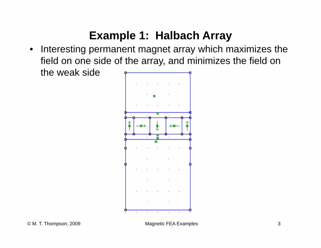
Example 1: Halbach ArrayI t ti t t hi h i i th• Interesting permanent magnet array which maximizes the field on one side of the array, and minimizes the field on the weak side
Magnetic FEA Examples 3© M. T. Thompson, 2009
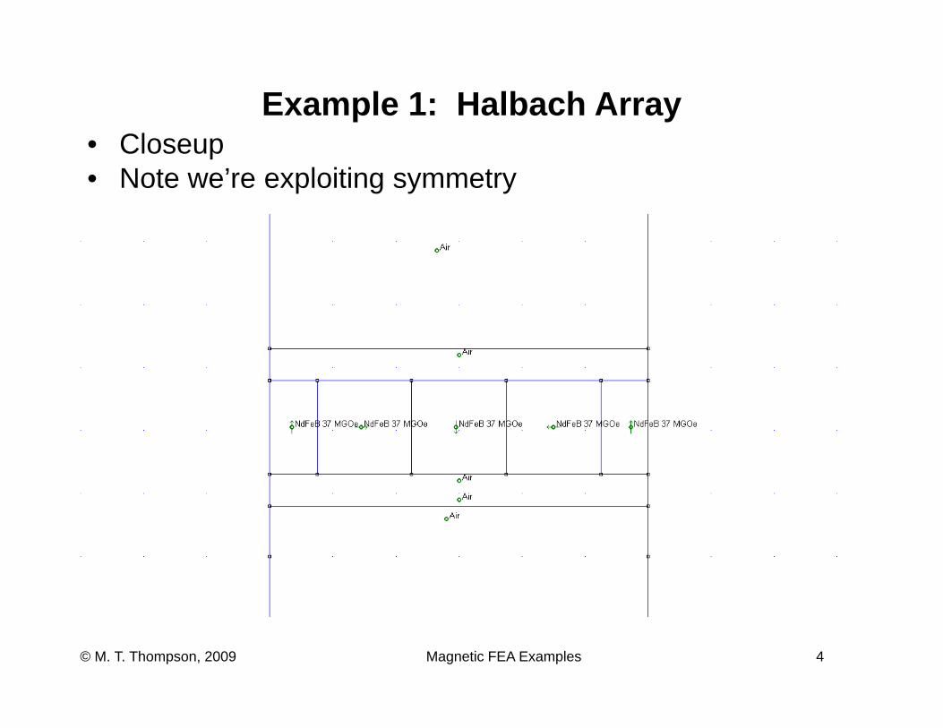
Example 1: Halbach ArrayCl• Closeup
• Note we’re exploiting symmetry
Magnetic FEA Examples 4© M. T. Thompson, 2009
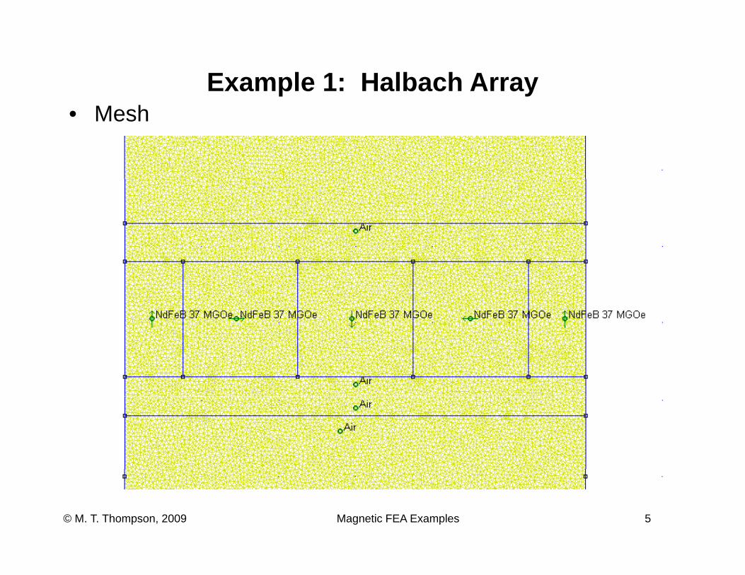
Example 1: Halbach ArrayM h• Mesh
Magnetic FEA Examples 5© M. T. Thompson, 2009
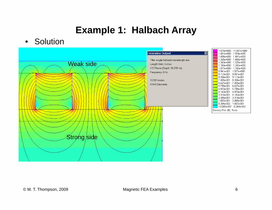
Example 1: Halbach ArrayS l ti• Solution
Weak sideWeak side
Strong side
Magnetic FEA Examples 6© M. T. Thompson, 2009
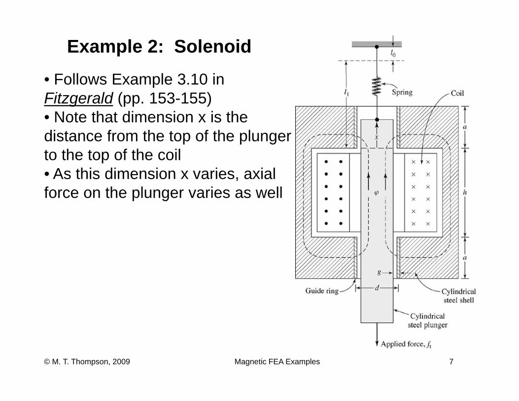
Example 2: Solenoid
F ll E l 3 10 i• Follows Example 3.10 in Fitzgerald (pp. 153-155)• Note that dimension x is the distance from the top of the plunger to the top of the coil• As this dimension x varies axial• As this dimension x varies, axial force on the plunger varies as well
Magnetic FEA Examples 7© M. T. Thompson, 2009
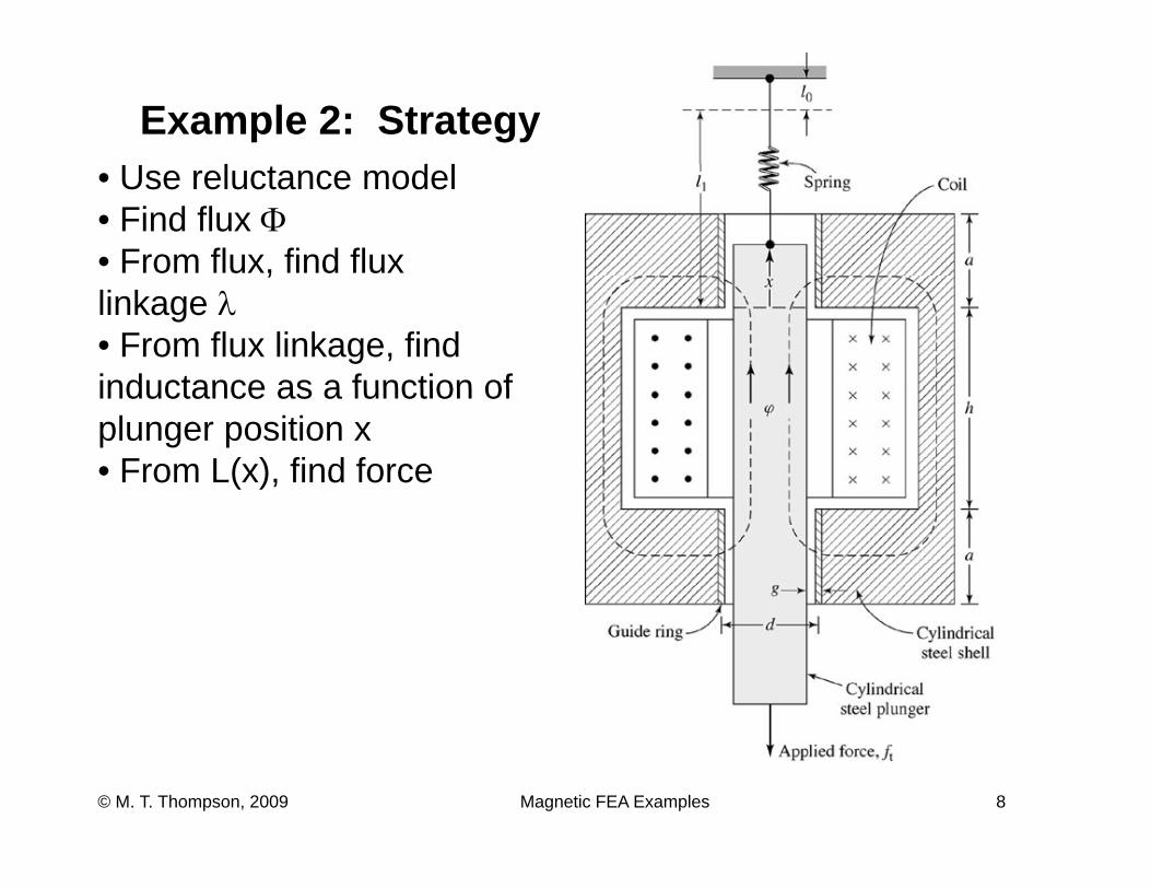
Example 2: StrategyU l d l• Use reluctance model
• Find flux Φ• From flux, find flux ,linkage λ• From flux linkage, find inductance as a function ofinductance as a function of plunger position x• From L(x), find force
Magnetic FEA Examples 8© M. T. Thompson, 2009
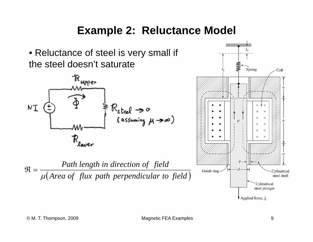
Example 2: Reluctance Model
• Reluctance of steel is very small if the steel doesn’t saturate
fieldofdirectioninlengthPathℜ ( )fieldtolarperpendicupathfluxofArea
fieldofdi ectioninlengthathμ
=ℜ
Magnetic FEA Examples 9© M. T. Thompson, 2009
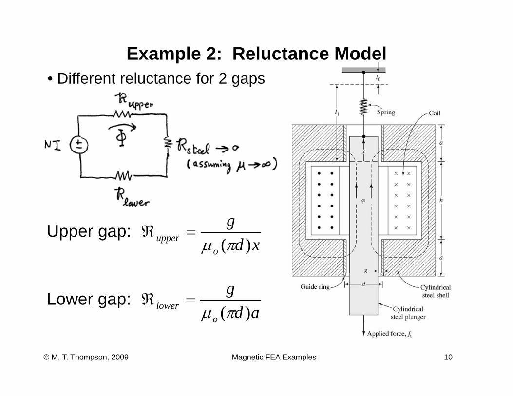
Example 2: Reluctance ModelDiff t l t f 2• Different reluctance for 2 gaps
gUpper gap: xd
g
oupper )(πμ
=ℜ
Lower gap: ad
g
olower )(πμ
=ℜ
Magnetic FEA Examples 10© M. T. Thompson, 2009
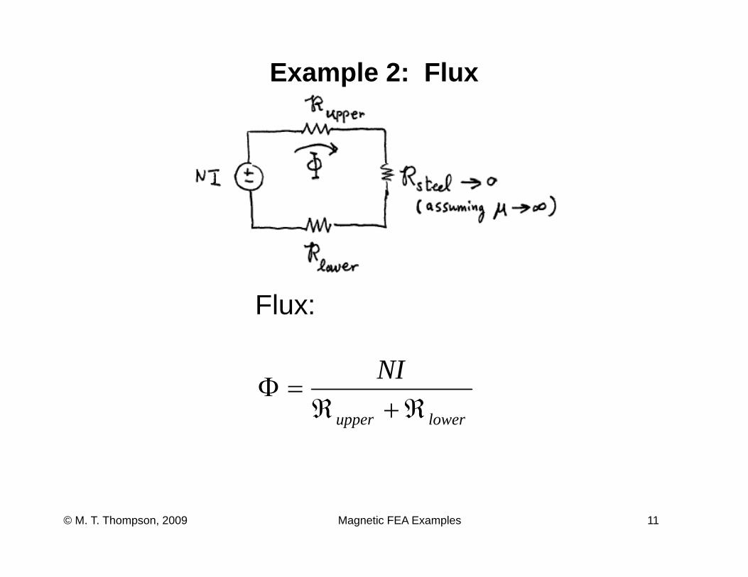
Example 2: Flux
Flux:
NI=Φ
lowerupper ℜ+ℜ
Magnetic FEA Examples 11© M. T. Thompson, 2009
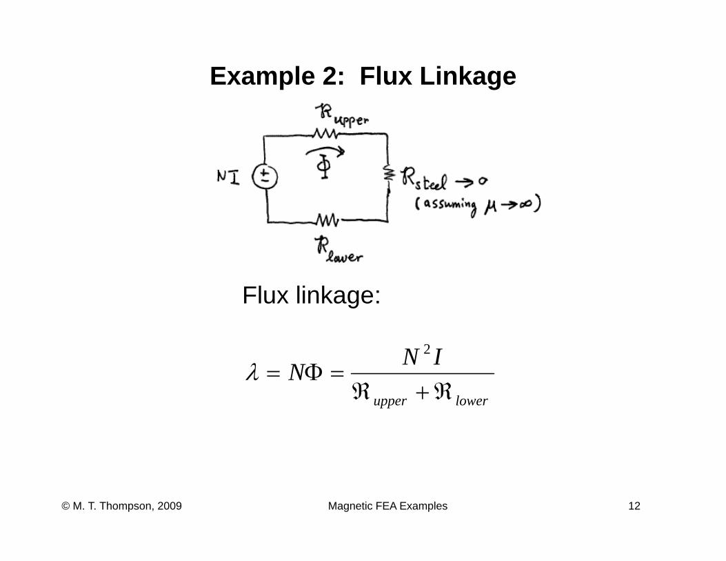
Example 2: Flux Linkage
Flux linkage:
INNℜ+ℜ
=Φ=2
λ lowerupper ℜ+ℜ
Magnetic FEA Examples 12© M. T. Thompson, 2009
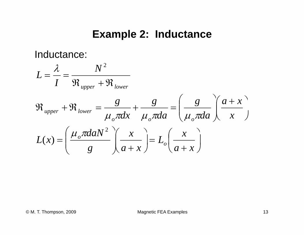
Example 2: Inductance
Inductance: NL
2λ
lowerupperIL
ℜ+ℜ==
⎟⎞
⎜⎛ +⎟⎞
⎜⎛ xaggg
⎟⎠⎞
⎜⎝⎛ +⎟⎟⎠
⎞⎜⎜⎝
⎛=+=ℜ+ℜ
xxa
dag
dag
dxg
ooolowerupper πμπμπμ
⎞⎛⎞⎛⎞⎛ xxdaN 2πμ⎟⎠⎞
⎜⎝⎛
+=⎟
⎠⎞
⎜⎝⎛
+⎟⎟⎠
⎞⎜⎜⎝
⎛=
xaxL
xax
gdaN
xL oo)(πμ
Magnetic FEA Examples 13© M. T. Thompson, 2009
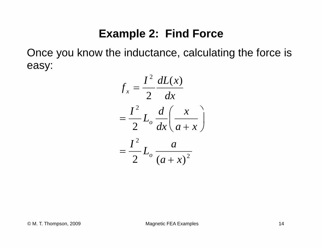
Example 2: Find ForceOnce you know the inductance, calculating the force is easy:
2 )(dLI
2
2 )(2
dIdx
xdLIf x
⎞⎛
=
2
2
2 xax
dxdLI
o ⎟⎠⎞
⎜⎝⎛
+=
2
2
)(2 xaaLI
o +=
Magnetic FEA Examples 14© M. T. Thompson, 2009
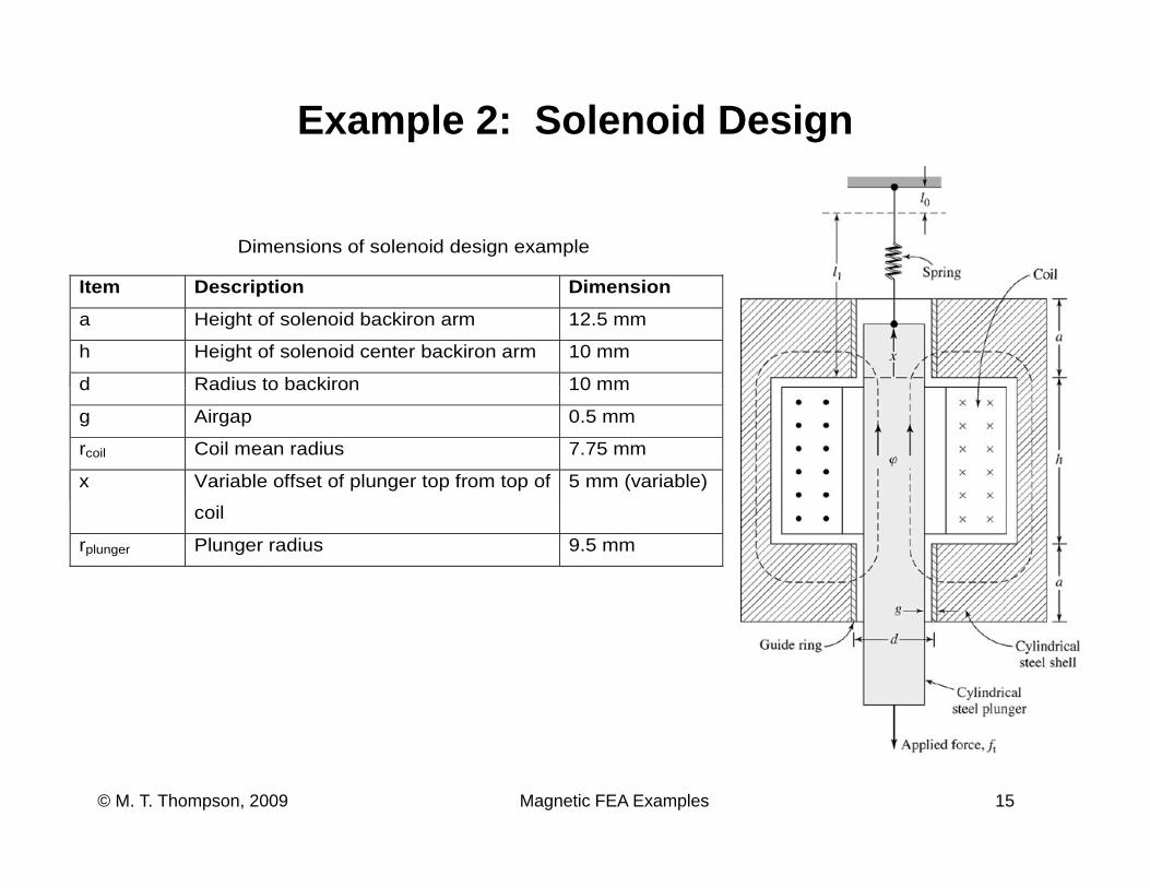
Example 2: Solenoid Design
Dimensions of solenoid design example
Item Description Dimension
a Height of solenoid backiron arm 12.5 mm
h Height of solenoid center backiron arm 10 mm
d Radius to backiron 10 mmd Radius to backiron 10 mm
g Airgap 0.5 mm
rcoil Coil mean radius 7.75 mm
x Variable offset of plunger top from top of 5 mm (variable)
coil
rplunger Plunger radius 9.5 mm
Magnetic FEA Examples 15© M. T. Thompson, 2009
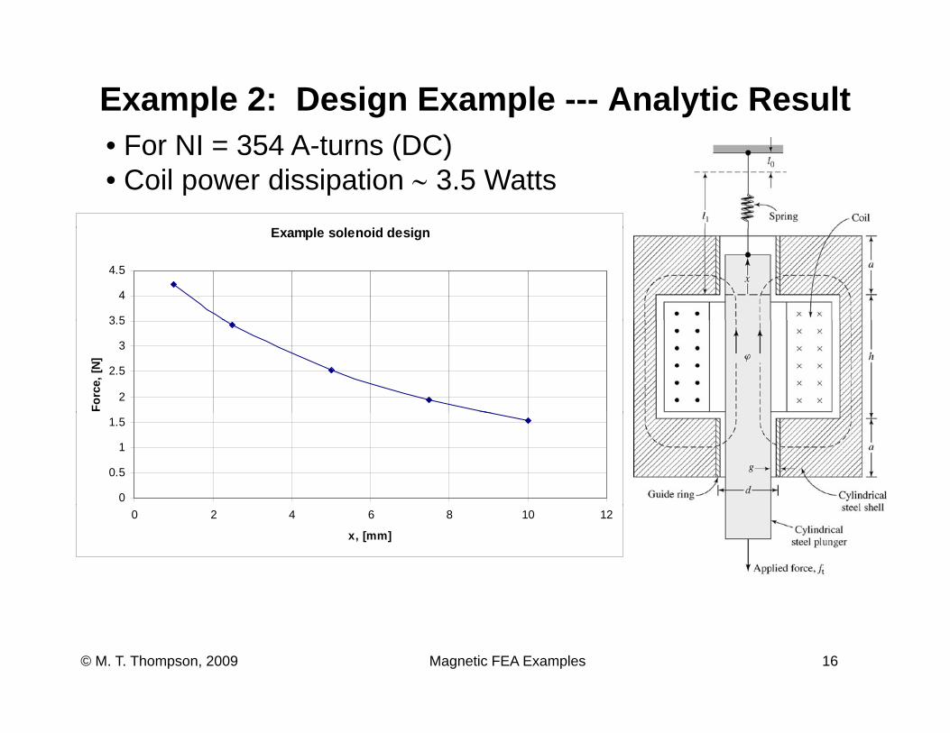
Example 2: Design Example --- Analytic ResultF NI 354 A t (DC)
E l l id d i
• For NI = 354 A-turns (DC)• Coil power dissipation ∼ 3.5 Watts
Example solenoid design
3 5
4
4.5
2
2.5
3
3.5
Forc
e, [N
]
0
0.5
1
1.5
0 2 4 6 8 10 12
x, [mm]
Magnetic FEA Examples 16© M. T. Thompson, 2009
Example 2: Simulation• “Trust, but verify” (R. Reagan, c. 1985)
Magnetic FEA Examples 17© M. T. Thompson, 2009
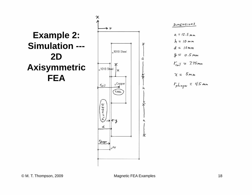
Example 2:Example 2: Simulation ---
2D Axisymmetric
FEA
Magnetic FEA Examples 18© M. T. Thompson, 2009
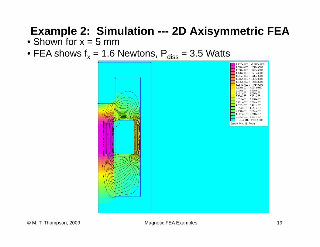
Example 2: Simulation --- 2D Axisymmetric FEA• Shown for x = 5 mm• FEA shows fx = 1.6 Newtons, Pdiss = 3.5 Watts
Magnetic FEA Examples 19© M. T. Thompson, 2009
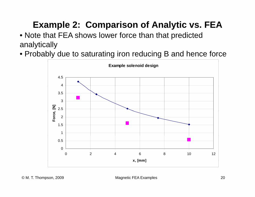
Example 2: Comparison of Analytic vs. FEA• Note that FEA shows lower force than that predictedNote that FEA shows lower force than that predicted analytically• Probably due to saturating iron reducing B and hence force
Example solenoid design
4
4.5
2.5
3
3.5
4
[N]
1
1.5
2
Forc
e,
0
0.5
0 2 4 6 8 10 12
x [mm]
Magnetic FEA Examples 20© M. T. Thompson, 2009
x, [mm]
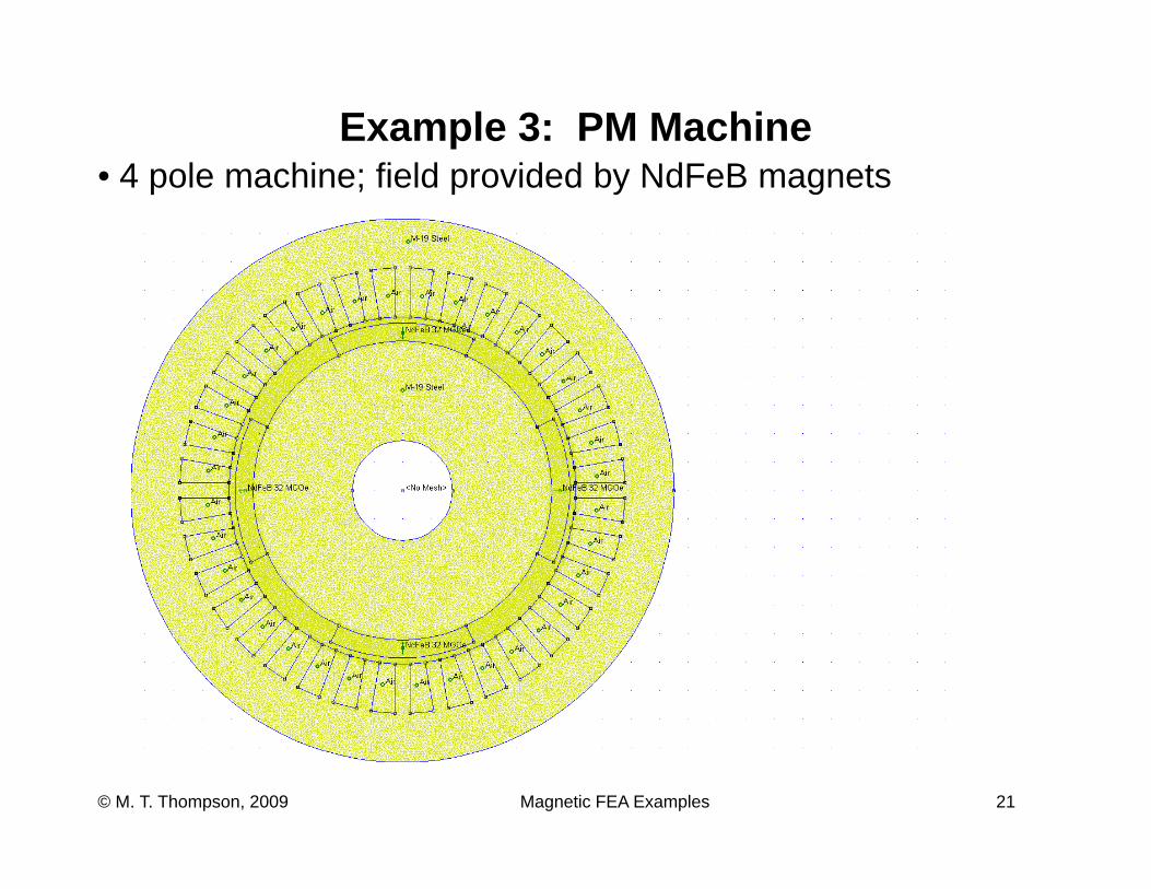
Example 3: PM Machine4 l hi fi ld id d b NdF B t• 4 pole machine; field provided by NdFeB magnets
Magnetic FEA Examples 21© M. T. Thompson, 2009
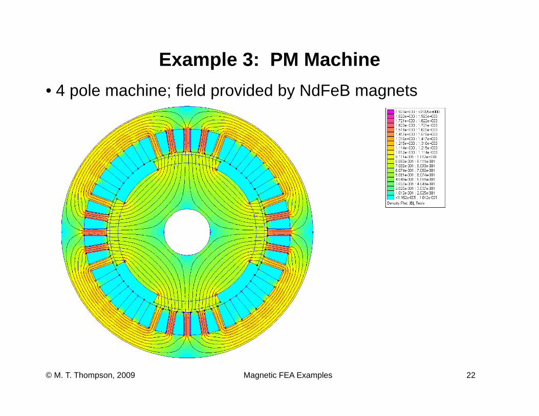
Example 3: PM Machine• 4 pole machine; field provided by NdFeB magnets
Magnetic FEA Examples 22© M. T. Thompson, 2009
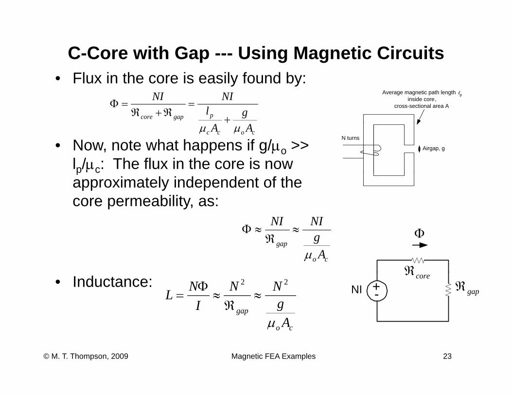
C-Core with Gap --- Using Magnetic CircuitsFl i th i il f d b• Flux in the core is easily found by:
Average magnetic path length lpinside core,
cross-sectional area A
pgapcore glNINI
+=
ℜ+ℜ=Φ
• Now, note what happens if g/μo >> lp/μc: The flux in the core is now
N turns
Airgap, g
cocc AA μμ
p capproximately independent of the core permeability, as:
NINIΦ
ℜco
gap
AgNINI
μ
≈ℜ
≈Φ
• Inductance: +-NIℜcore
ℜgap
gap
Ag
NNI
NL
μ
22
≈ℜ
≈Φ
=
Magnetic FEA Examples 23© M. T. Thompson, 2009
co Aμ
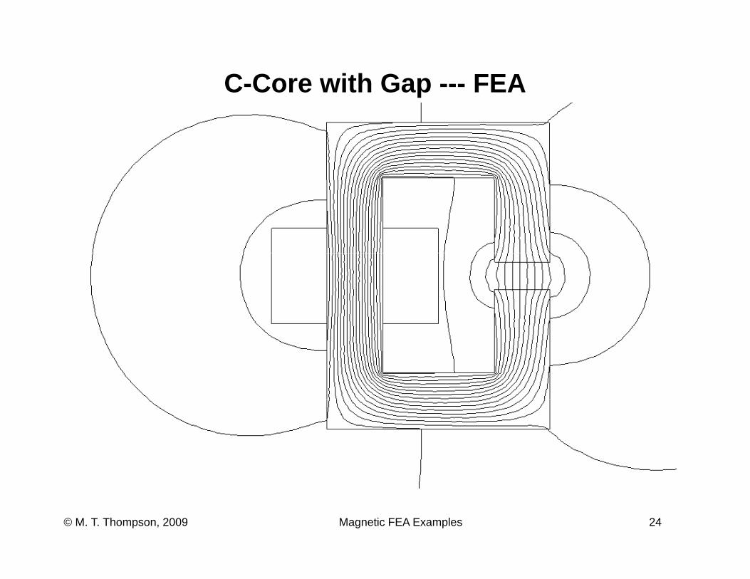
C-Core with Gap --- FEA
Magnetic FEA Examples 24© M. T. Thompson, 2009
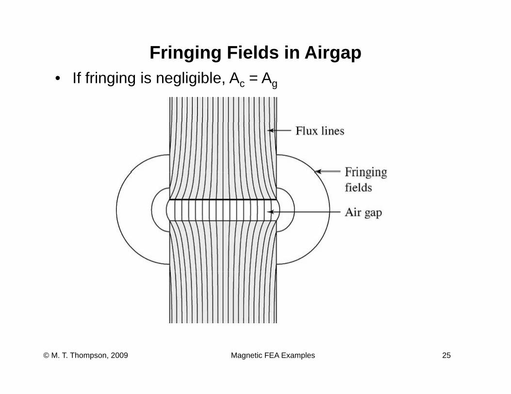
Fringing Fields in AirgapIf f i i i li ibl A A• If fringing is negligible, Ac = Ag
Magnetic FEA Examples 25© M. T. Thompson, 2009
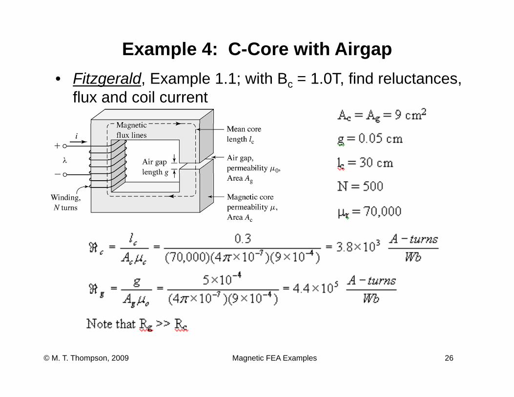
Example 4: C-Core with AirgapFit ld E l 1 1 ith B 1 0T fi d l t• Fitzgerald, Example 1.1; with Bc = 1.0T, find reluctances, flux and coil current
Magnetic FEA Examples 26© M. T. Thompson, 2009
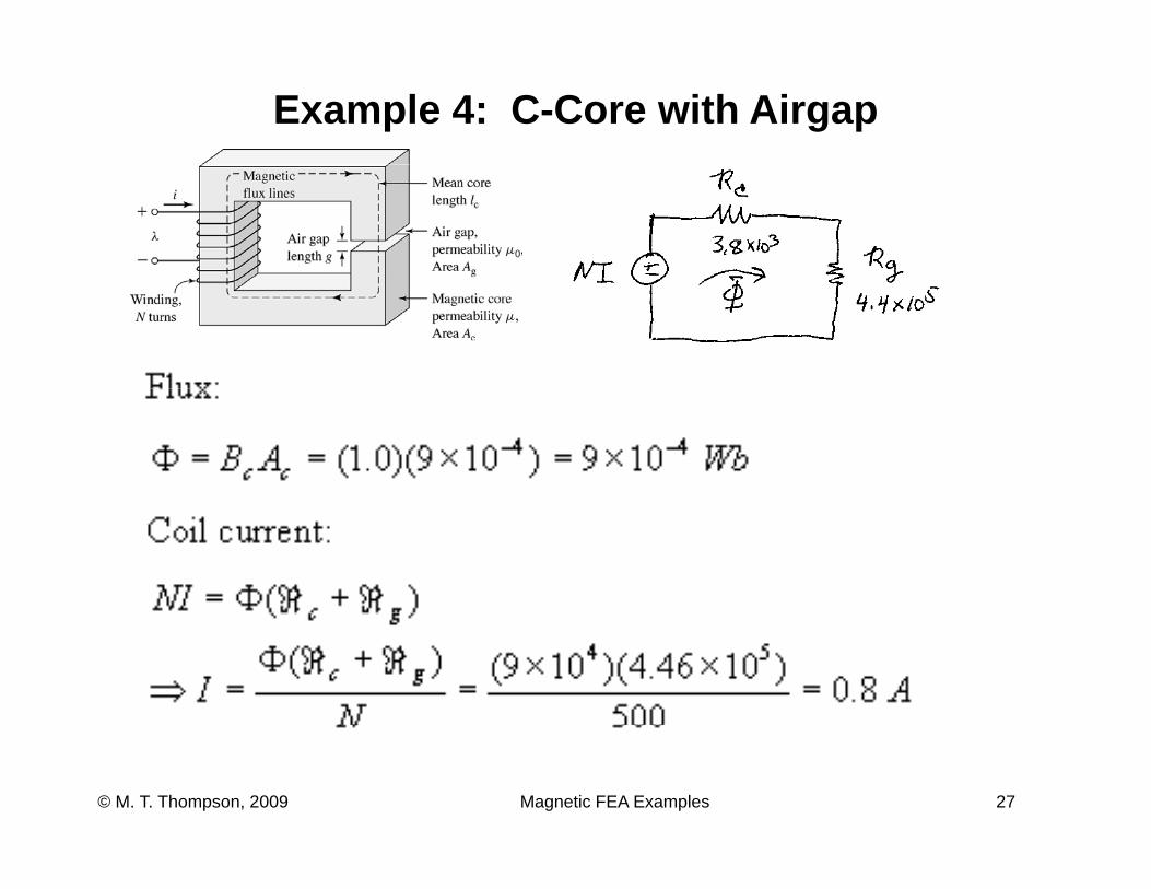
Example 4: C-Core with Airgap
Magnetic FEA Examples 27© M. T. Thompson, 2009
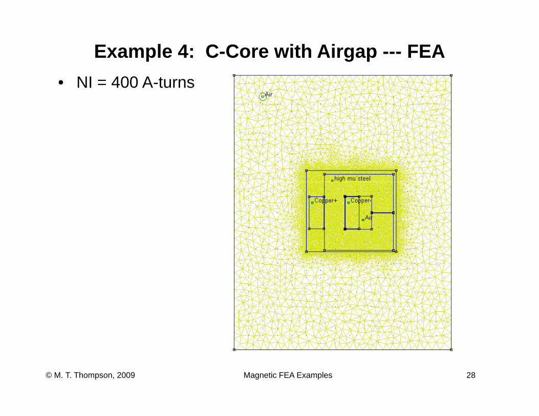
Example 4: C-Core with Airgap --- FEANI 400 A t• NI = 400 A-turns
Magnetic FEA Examples 28© M. T. Thompson, 2009
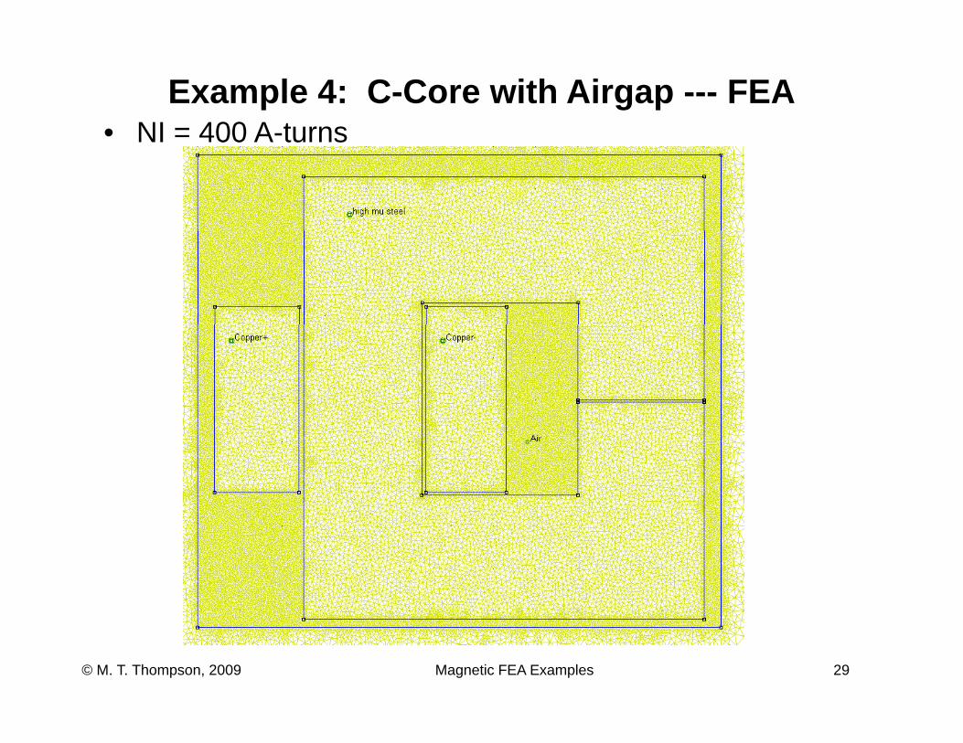
Example 4: C-Core with Airgap --- FEA• NI = 400 A-turnsNI 400 A turns
Magnetic FEA Examples 29© M. T. Thompson, 2009
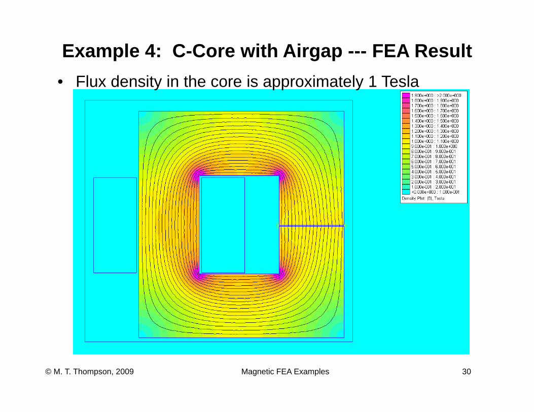
Example 4: C-Core with Airgap --- FEA ResultFl d it i th i i t l 1 T l• Flux density in the core is approximately 1 Tesla
Magnetic FEA Examples 30© M. T. Thompson, 2009
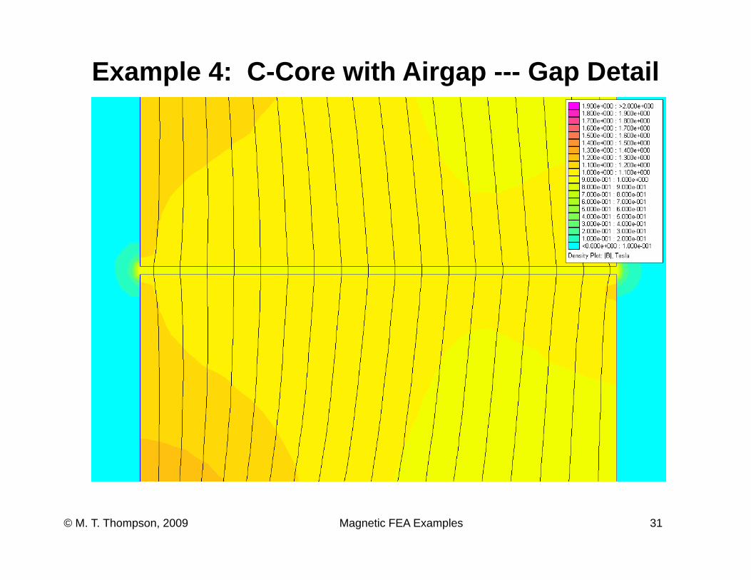
Example 4: C-Core with Airgap --- Gap Detail
Magnetic FEA Examples 31© M. T. Thompson, 2009
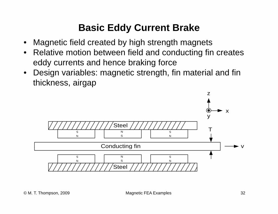
Basic Eddy Current BrakeM ti fi ld t d b hi h t th t• Magnetic field created by high strength magnets
• Relative motion between field and conducting fin creates eddy currents and hence braking force
z
y g• Design variables: magnetic strength, fin material and fin
thickness, airgap
x
z
y
Steel
Conducting fin
NSN
SNS
v
T
Conducting fin
Steel
NSN
S
v
NS
Magnetic FEA Examples 32© M. T. Thompson, 2009
Magnetic Induction in ECBs• Relative motion between permanent magnets and
conducting sheet means that there is a time-varying magnetic field impinging on the sheetmagnetic field impinging on the sheet– Magnets or conducting sheet can be moving; it’s
relative movement that’s important• This time varying magnetic field creates circulating
(eddy) currents in conducting sheetM ti i d ti i th i i l b hi h th– Magnetic induction is the principle by which these eddy currents are induced (by Faraday’s Law)
• Eddy currents mean power dissipation in sheet, and aEddy currents mean power dissipation in sheet, and a magnetic drag force acting on the sheet
forcesdPJEdBd >→→<→→
rrr
Magnetic FEA Examples 33© M. T. Thompson, 2009
forcesdissPJEdt >→→<→→
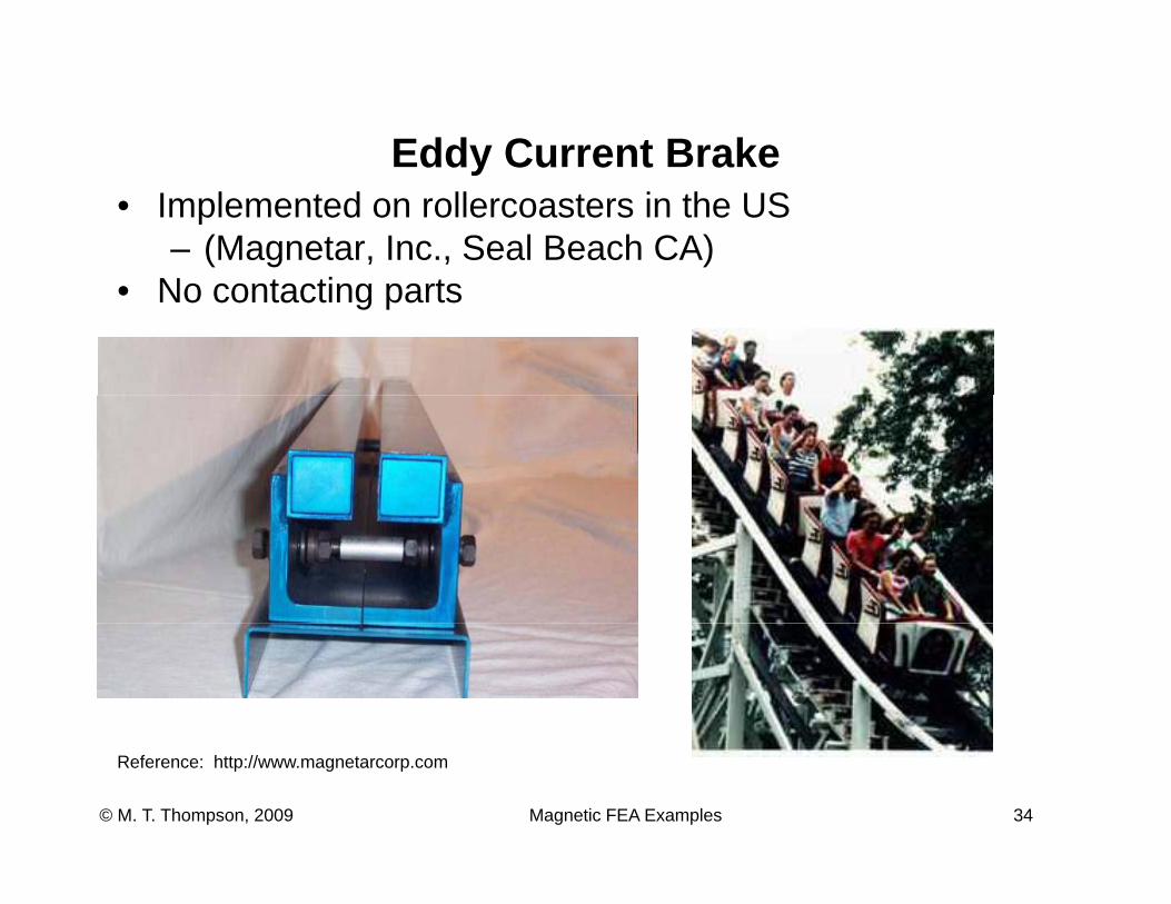
Eddy Current Brakeddy Cu e t a e• Implemented on rollercoasters in the US
– (Magnetar, Inc., Seal Beach CA) N t ti t• No contacting parts
Magnetic FEA Examples 34© M. T. Thompson, 2009
Reference: http://www.magnetarcorp.com
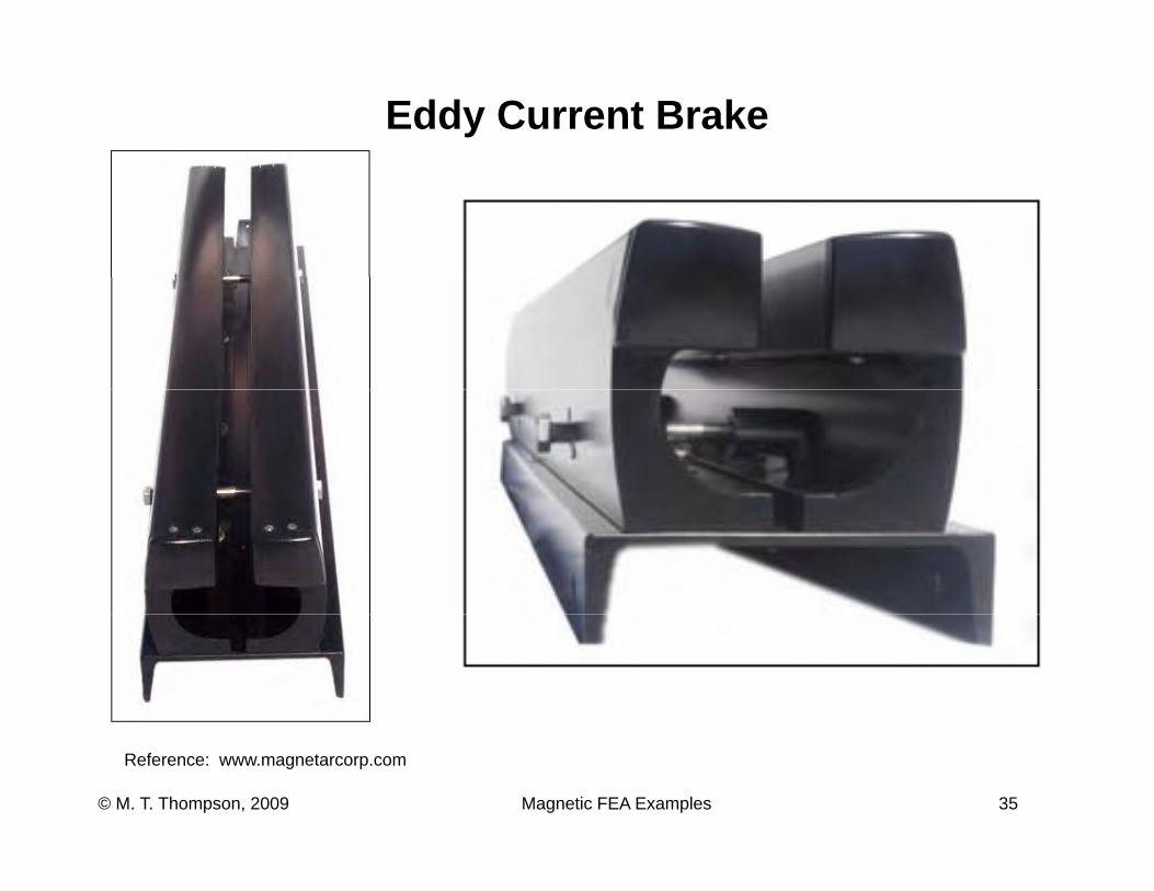
Eddy Current Brake
Magnetic FEA Examples 35© M. T. Thompson, 2009
Reference: www.magnetarcorp.com
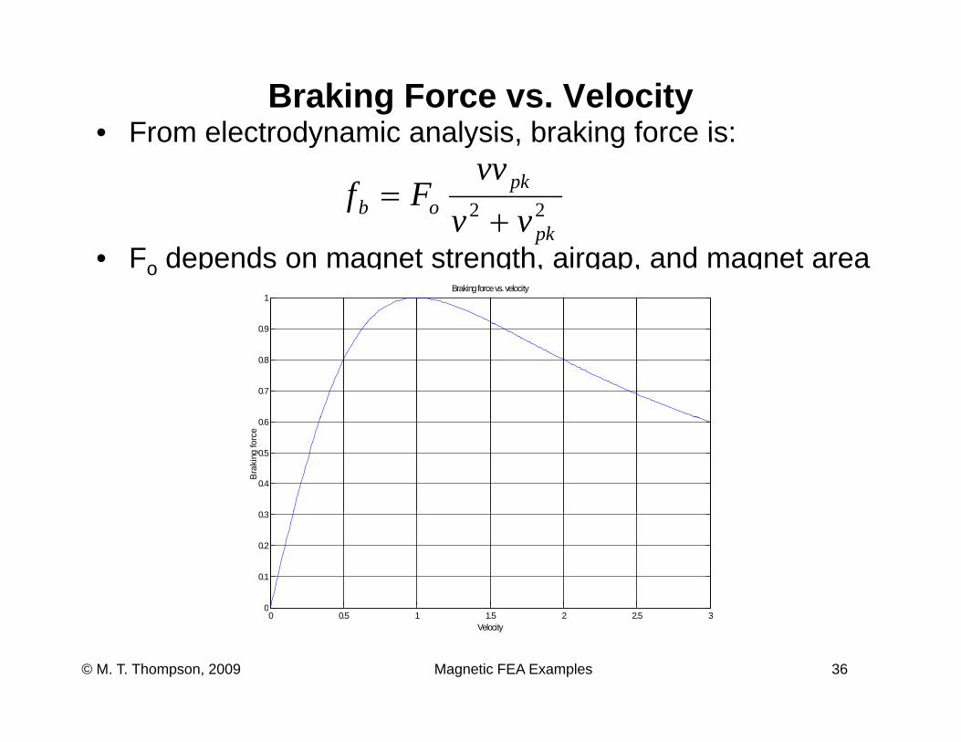
Braking Force vs. Velocity• From electrodynamic analysis braking force is:From electrodynamic analysis, braking force is:
22k
pkob vv
vvFf
+=
• Fo depends on magnet strength, airgap, and magnet area1
Braking force vs. velocity
pkvv +
0.7
0.8
0.9
03
0.4
0.5
0.6
Bra
king
forc
e
0
0.1
0.2
0.3
Magnetic FEA Examples 36© M. T. Thompson, 2009
0 0.5 1 1.5 2 2.5 30
Velocity
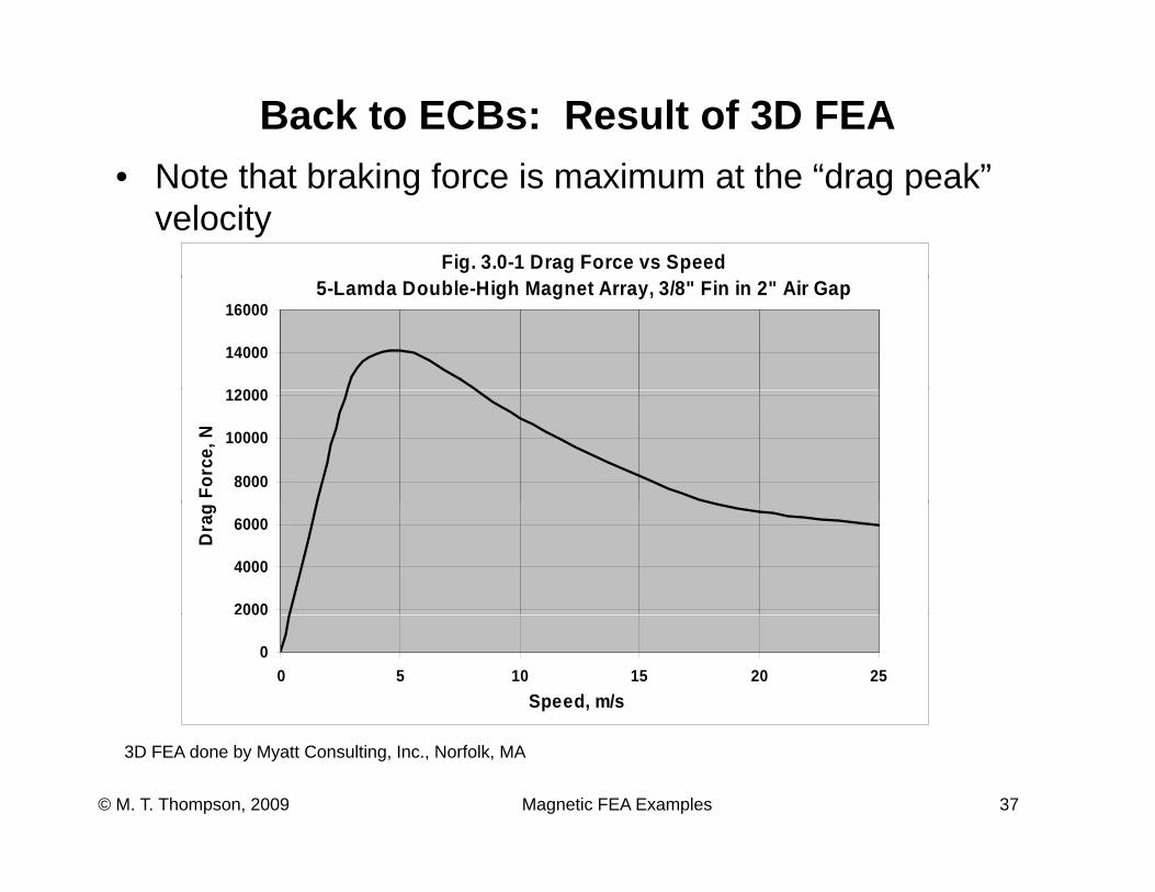
Back to ECBs: Result of 3D FEAN t th t b ki f i i t th “d k”• Note that braking force is maximum at the “drag peak” velocity
Fig. 3.0-1 Drag Force vs Speed5-Lamda Double-High Magnet Array, 3/8" Fin in 2" Air Gap
12000
14000
16000
8000
10000
12000
Forc
e, N
2000
4000
6000
Dra
g
0
000
0 5 10 15 20 25Speed, m/s
Magnetic FEA Examples 37© M. T. Thompson, 2009
3D FEA done by Myatt Consulting, Inc., Norfolk, MA
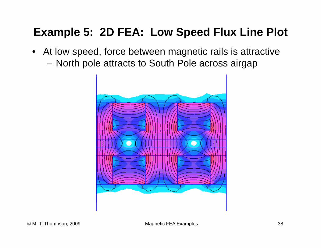
Example 5: 2D FEA: Low Speed Flux Line Plot• At low speed, force between magnetic rails is attractive
– North pole attracts to South Pole across airgap
Magnetic FEA Examples 38© M. T. Thompson, 2009
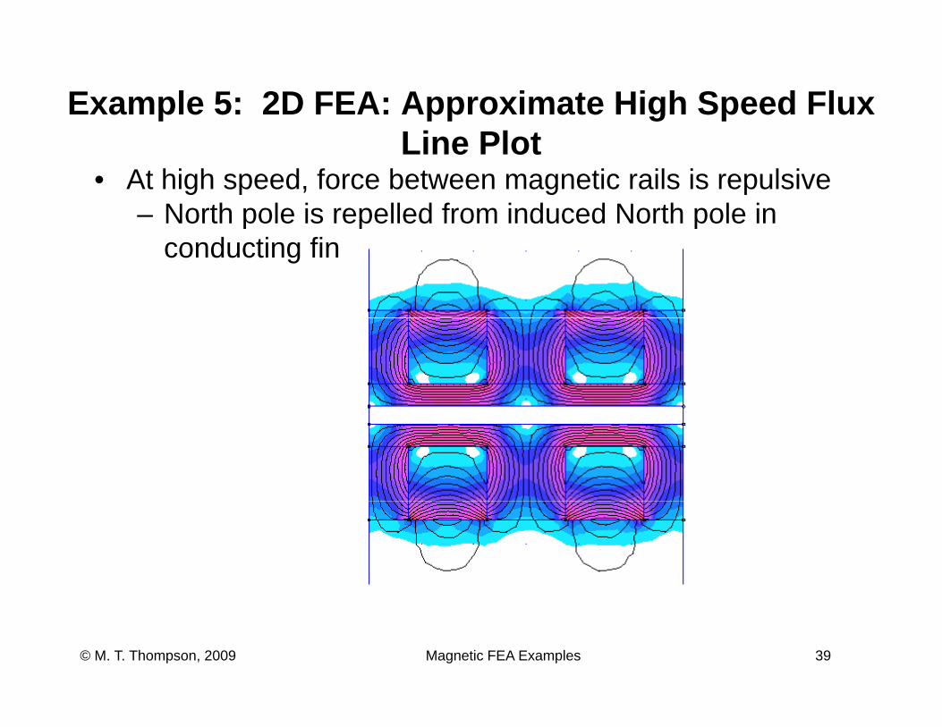
Example 5: 2D FEA: Approximate High Speed Flux Li Pl tLine Plot
• At high speed, force between magnetic rails is repulsive– North pole is repelled from induced North pole in p p p
conducting fin
Magnetic FEA Examples 39© M. T. Thompson, 2009
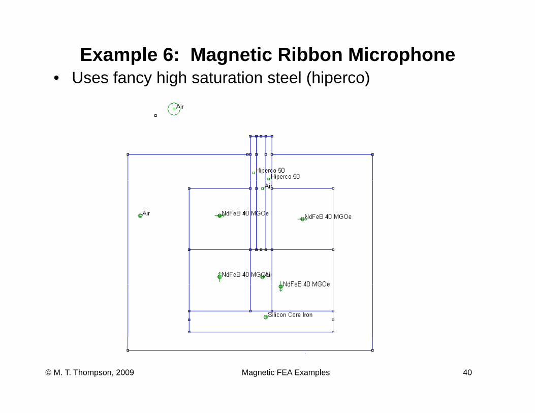
Example 6: Magnetic Ribbon Microphone• Uses fancy high saturation steel (hiperco)• Uses fancy high saturation steel (hiperco)
Magnetic FEA Examples 40© M. T. Thompson, 2009
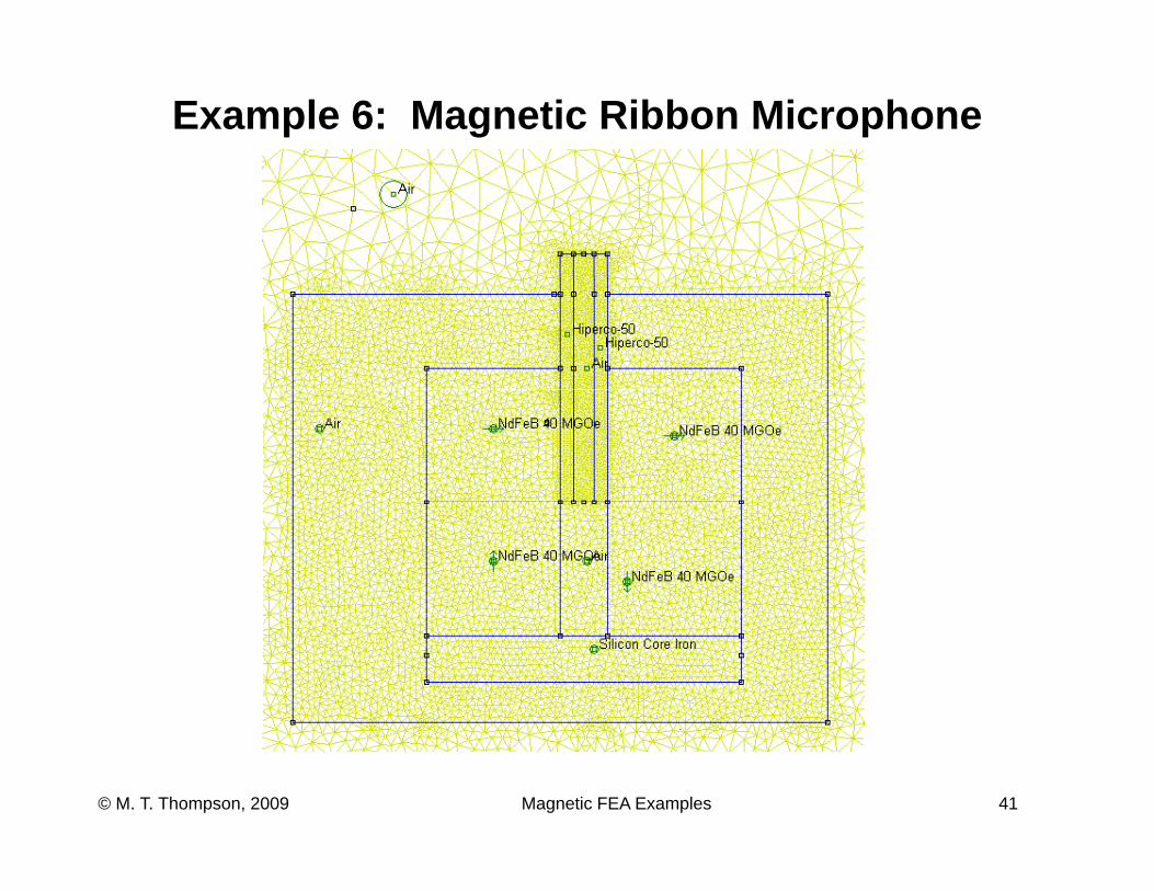
Example 6: Magnetic Ribbon Microphone
Magnetic FEA Examples 41© M. T. Thompson, 2009
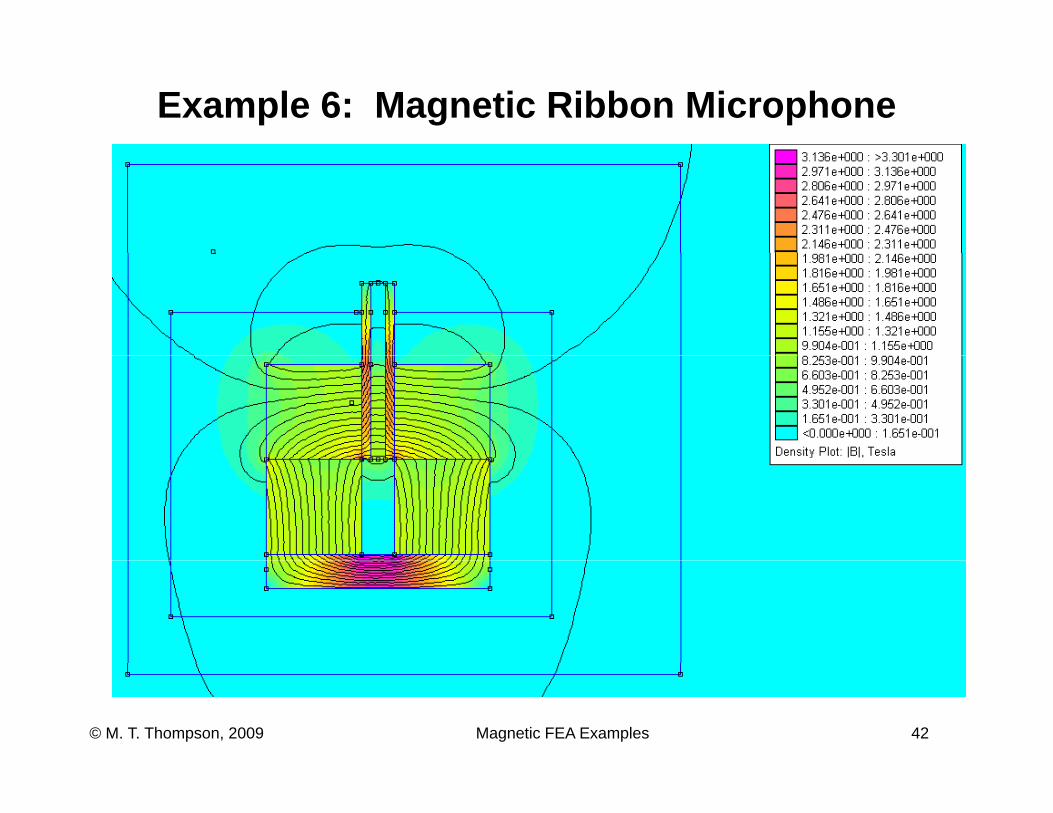
Example 6: Magnetic Ribbon Microphone
Magnetic FEA Examples 42© M. T. Thompson, 2009
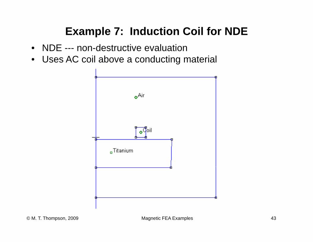
Example 7: Induction Coil for NDENDE d t ti l ti• NDE --- non-destructive evaluation
• Uses AC coil above a conducting material
Magnetic FEA Examples 43© M. T. Thompson, 2009
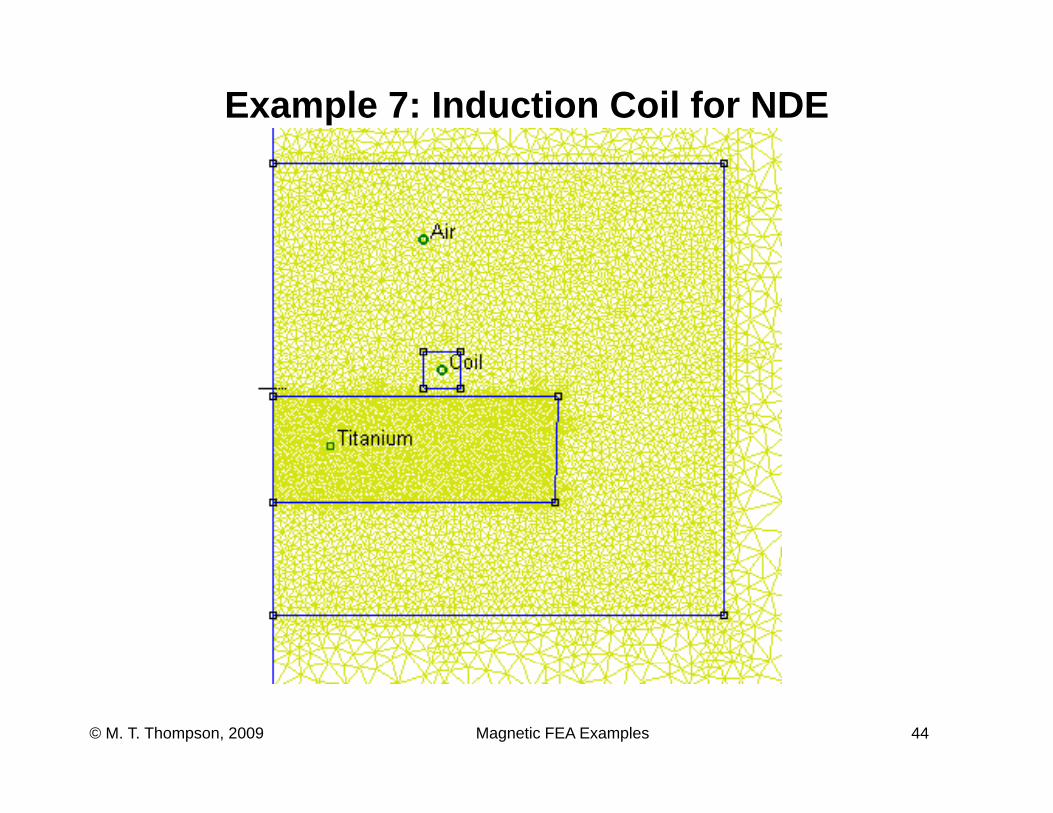
Example 7: Induction Coil for NDE
Magnetic FEA Examples 44© M. T. Thompson, 2009
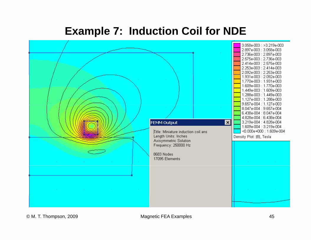
Example 7: Induction Coil for NDE
Magnetic FEA Examples 45© M. T. Thompson, 2009
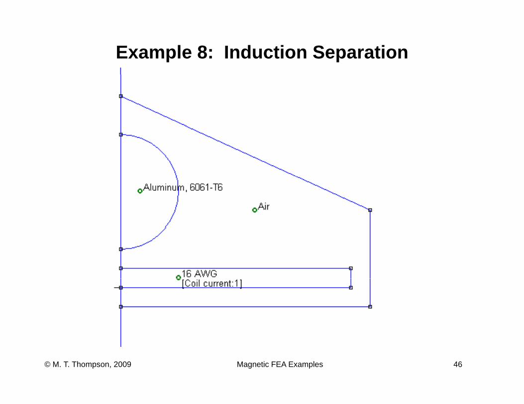
Example 8: Induction Separation
Magnetic FEA Examples 46© M. T. Thompson, 2009
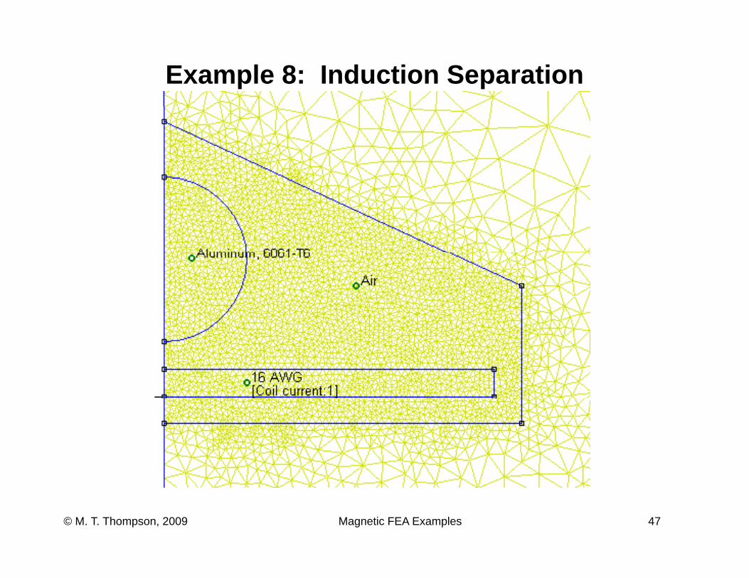
Example 8: Induction Separation
Magnetic FEA Examples 47© M. T. Thompson, 2009
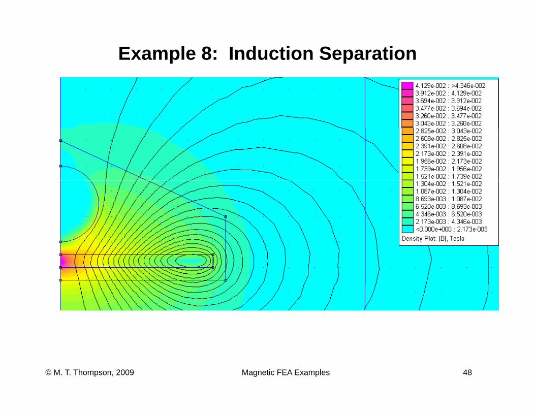
Example 8: Induction Separation
Magnetic FEA Examples 48© M. T. Thompson, 2009
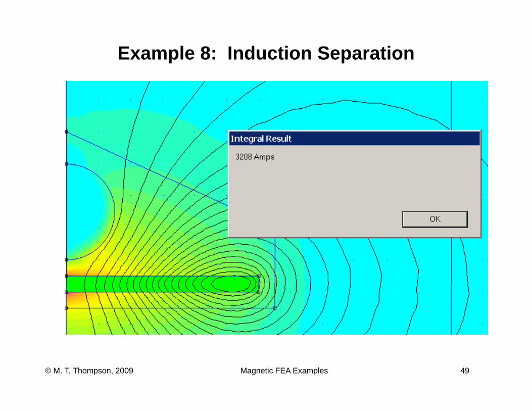
Example 8: Induction Separation
Magnetic FEA Examples 49© M. T. Thompson, 2009
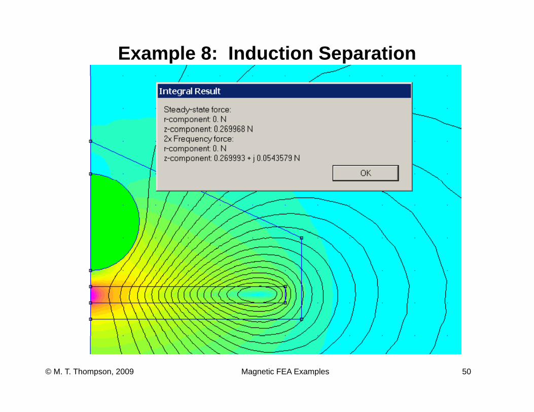
Example 8: Induction Separation
Magnetic FEA Examples 50© M. T. Thompson, 2009
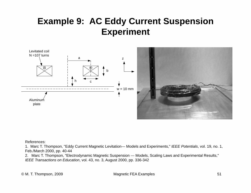
Example 9: AC Eddy Current Suspension Experimentp
a z
Levitated coilN =107 turns
rb
h c
w = 10 mm
Aluminumplate
References: 1. Marc T. Thompson, "Eddy Current Magnetic Levitation--- Models and Experiments," IEEE Potentials, vol. 19, no. 1, Feb./March 2000, pp. 40-44 2. Marc T. Thompson, "Electrodynamic Magnetic Suspension --- Models, Scaling Laws and Experimental Results,"
Magnetic FEA Examples 51© M. T. Thompson, 2009
p y g p g pIEEE Transactions on Education, vol. 43, no. 3, August 2000, pp. 336-342
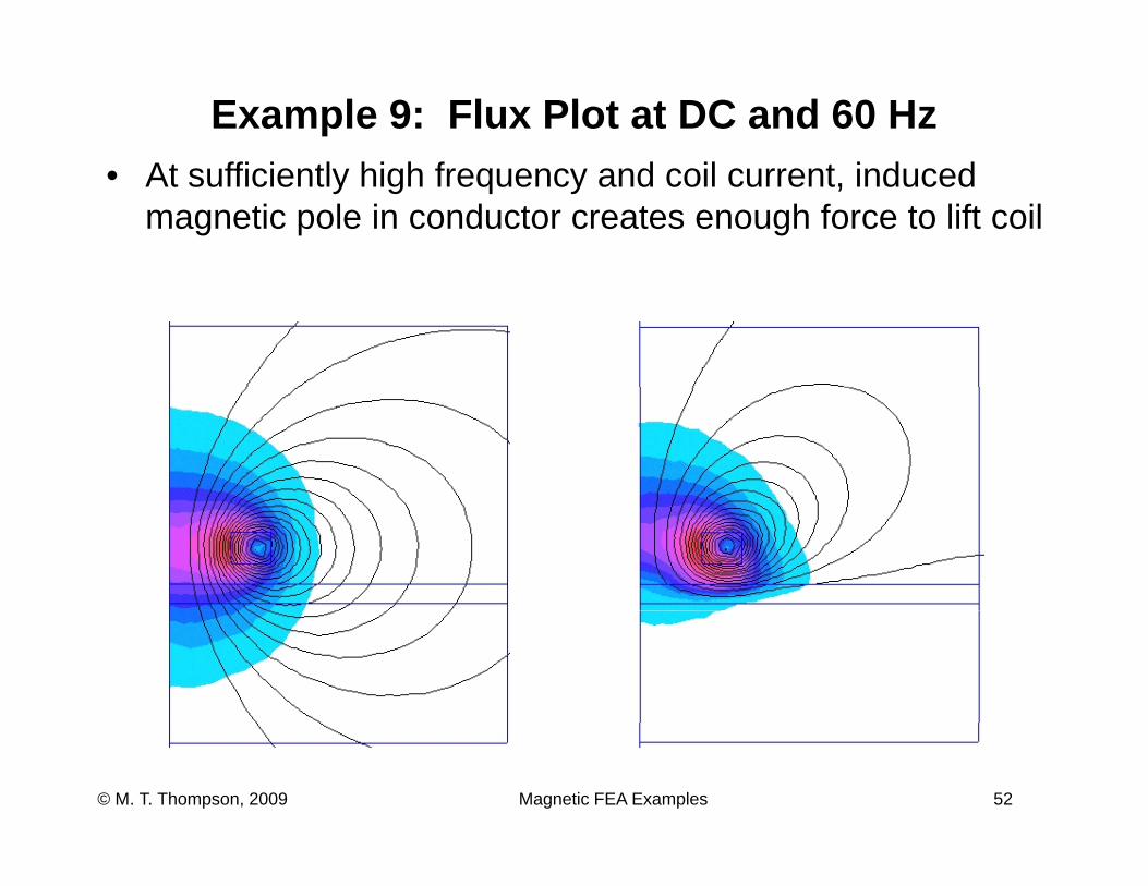
Example 9: Flux Plot at DC and 60 HzAt ffi i tl hi h f d il t i d d• At sufficiently high frequency and coil current, induced magnetic pole in conductor creates enough force to lift coil
Magnetic FEA Examples 52© M. T. Thompson, 2009
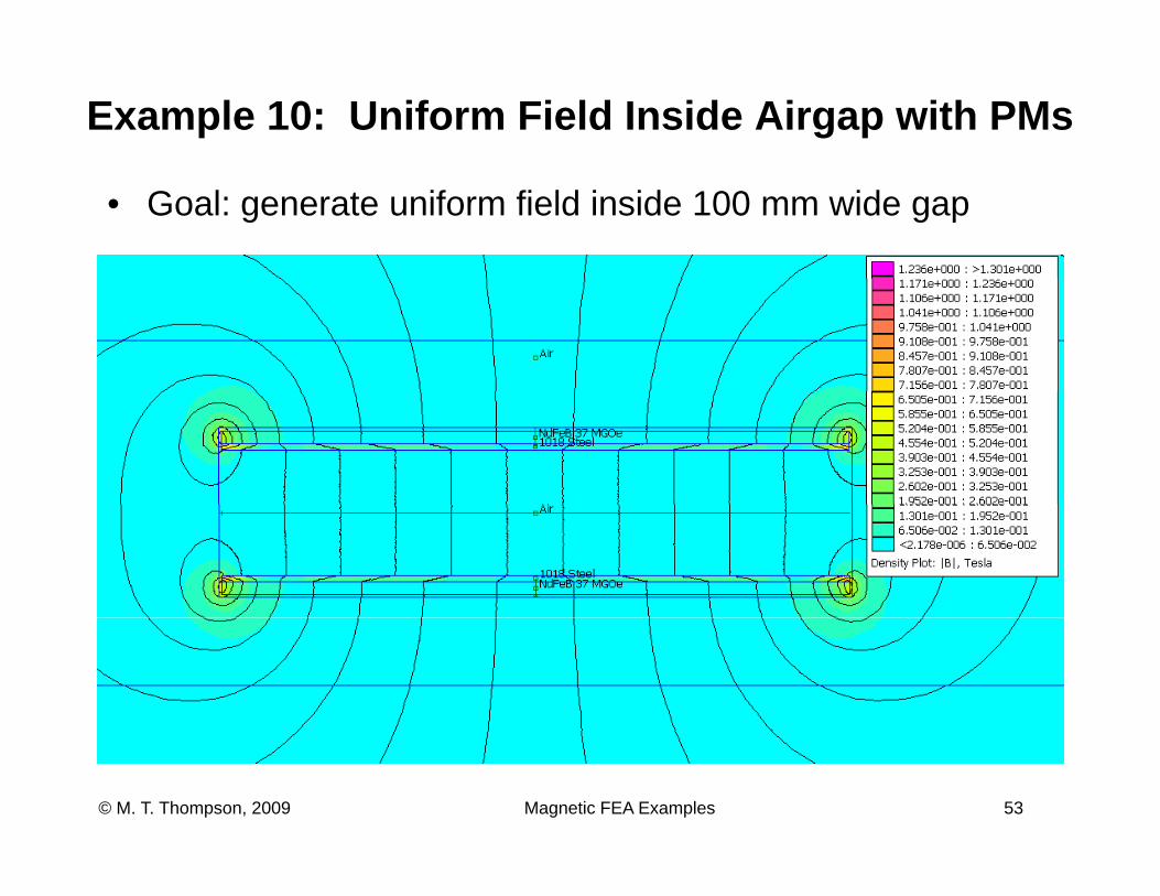
Example 10: Uniform Field Inside Airgap with PMs
• Goal: generate uniform field inside 100 mm wide gap
Magnetic FEA Examples 53© M. T. Thompson, 2009
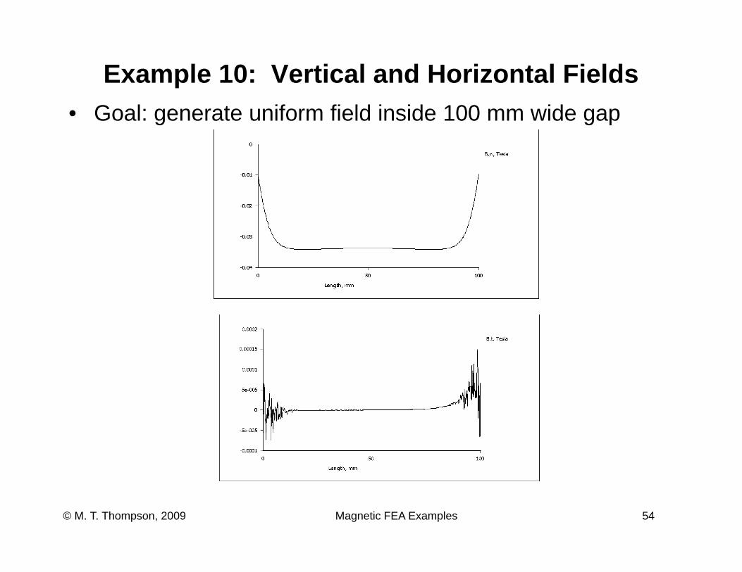
Example 10: Vertical and Horizontal FieldsG l t if fi ld i id 100 id• Goal: generate uniform field inside 100 mm wide gap
Magnetic FEA Examples 54© M. T. Thompson, 2009
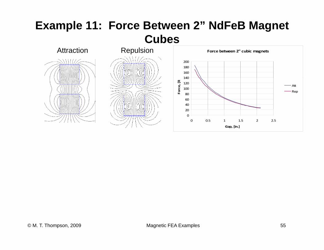
Example 11: Force Between 2” NdFeB Magnet Cubes
Attraction Repulsion Force between 2" cubic magnets
140
160
180
200
20
40
60
80
100
120
140
Force, [lb
Att
Rep
0
20
0 0.5 1 1.5 2 2.5
Gap, [in.]
Magnetic FEA Examples 55© M. T. Thompson, 2009
ReferencesD id M k Ph D (F t Mill ) FEMM (Fi it• David Meeker, Ph.D., (Foster-Miller), FEMM (Finite Element Method Magnetics
Magnetic FEA Examples 56© M. T. Thompson, 2009


![Plf Fi e 30d [PDF Library]](https://img.pdfslide.us/doc/110x75/5478ddcbb479596d098b45e0/plf-fi-e-30d-pdf-library.jpg)