Embed Size (px)
Citation preview

NOTE TO USERS
The original manuscript received by UMI contains broken or light print. All efforts were made to acquire the highest
quality manuscript from the author or school. Page(s) were microfilmed as received.
This reproduction is the best copy available


A Virtual Network Approach
to Network Resources Management
Andrew Do-Sung Jun
A thesis submitted in conformity with the requirements for the degree of Master of Applied Science
Graduate Department of Electrical and Cornputer Engineering University of Toronto
O Copyright by Andrew Do-Sung Jun 1998

National Library 8ibliotfièque nationale du Canada
Acquisitions and Acquisitions et Bibliographie Services services bibliographiques
395 Wellington Street 395. rue Wellington OttawaON K 1 A W Ottawa ON K1A ON4 Canada Canada
The author has granted a non- exclusive licence allowing the National Library of Canada to reproduce, loan, distribute or seil copies of this thesis in microform, paper or electronic formats.
The author retains ownership of the copyright in this thesis. Neither the thesis nor substantial extracts fiom it may be printed or othenivise reproduced without the author's permission.
L'auteur a accordé une licence non exclusive permettant à la Biblotheque nationale du Canada de reproduire, prêter, distribuer ou vendre des copies de cette thèse sous la forme de microfiche/film, de reproduction sur papier ou sur format électronique.
L'auteur conserve la propriété du droit d'auteur qui protège cette thèse. Ni la thèse ni des extraits substantiels de celle-ci ne doivent être imprimés ou autrement reproduits sans son autorisation.

A Virtuai Network Approach
to Network Resources Management
hdrew Do-Sung Jun
Master of Applied Science. 1998
Graduate Department of Electrical and Computer Engineering
University of Toronto
Abstract
In this thesis. we discuss the virtual network concepts and introduce a management
architecture for the control of virtual networks. The management architecture is intended
to provide a programmable networking environment, where multiple virtual networks c m
be generated out of a single physical network to be utilized for various management
purposes. We first defme a virtuai network and related concepts in a genenc manner;
discuss how physical network resources can be allocated to virtual networks: and present
how an hierarchy of virtual networks can be created. We then introduce the vimiai
network resources management architecture. The management architecture is designed
moduiarly to be scalable over geographical and administrative boundaries. Lastly, we
present a dynamic binding technique that allows customization of network control and
management Functions, and a real-time bandwidth management technique that enables
network-level multiplexing.
Acknowledgements
1 would like to express my sincere gratitude to my supervisor, Prof. A. Leon-Garcia, for
his invaluable advice, guidance, patience, encouragement, and support throughout the
course of this thesis. 1 would also like to thank Dr, Muhammad Jaseemuddin for his
comments and suggestions that were valuable in the preparation of the thesis.
Speciai thanks are owed to my parents, Bong-Kook Jun and Soo-Ran Sun, to the rest of
my family? and also to rny wife, Enta Hae-Ran Kim, for their encouragement and
continuous support.
iii

Table of Contents
Table of Contents ............................................................................................................. iv
List of Figures ................................................................................................................... vi
1 . In~oduction .................................................................................................................... 1
1 . 1 Motivation ..................... ., .......................................................................................... 1
1.2 Objective and Scope ................................................................................................... 3
. . 1.3 Research Context and Contnbubon ....................................................................... .....5
1 -4 Organization of the Thesis .......................................................................................... 7
2 . Architectural Concepts and Principles ....................................................................... .9
2.1 integration of Control and Management Functions ................................................. 9
2 . I . I Management Functions ................................................................................... I I
2.1.2 Control Frrnctions .............................................................................................. I Z
.......................................................................... 2.2 Network Layering and Partitioning 14
2.3 Manager-Agent Paradigrn and Functional Layering ................................................. 16
.......................................................................................... 3 . Virtual Network Concepts 19
3.1 Virtual Networks and Virtual Network Resources .................... .... .................... 19
3 -2 Abstraction of Network Resources ........................................................................... 24
3.2.1 Resource Representation Problem .................................................................... -25
3.2.2 Interfacing Virtual and Physicd Resources ...................................................... -28
3.3 VN Organization and Management Operations ....................................................... -30

9 .................................................................................. 3 -4 Cornparison of VN Proposals -3 2
................................................................. 4 . Virtual Network Resources Management -35
............................................................................................... 4.1 Overall Architecture -35
4.2 V h a l Network Resources Management S ystem .................................................. - 3 7
4.2. I Network Management Layer Functiom ............................................................ -38
........................................................... 42.2 Resource Management Layer Functions -41
4 2 . 3 Setting up a New W .................................. -6
................................................................... 4.3 Federation of Subnet VNRM Systems -50
5 . Customer Control of Virtual Networks ..................................................................... 54
5.1 Customization of Network Control and Management .............................................. 54
........................................................................................ 5 -2 Bandwidth Management - 3 6
6 . Conclusion .................................................................................................................... 59
References ......................................................................................................................... 61

List of Figures
Figure 2-1 Network Layering and Partitionhg ........................ ... ................................. 15
Figure 2-2 Manager-Agent Paradigm and Functional Layering ........................................ 17
Figure 3-1 Physical and Vimial Networks and their Resources ........................................ 20
33 Figure 3-2 Partitioning and Composition of VNRs for spawning of a VN . ........................
Figure 3-3 Resource Representations and Allocations ..................................................... 2 6
Figure 3-4 Two-class Equivalent Bandwidth Region ...................................................... -29
Figure 3-5 Organization of VNs ........................................................................................ 1
Figure 4- 1 Overall architecture of VNRM system ........................................................... - 3 6
Figure 4-2 Functionai and Information Models of VNRM system .................................... 37
Figure 4-3 Functional and Lnformation Models of Resource Agent ................................. .42
Figure 4-4 Resource Representations and Admission Controis ......................................... 45
Figure 4-5 Creation and Provisioning of a VN .................................................................. 46
Figure 4-6 Hierarchical Federation of the VNRM Systems ............................................... 1
Figure 4-7 Example of VNRM System Federation ...................................................... 52
Figure 5- 1 Customer Control of Virtual Networks ............................................................ 55
Figure 5-2 Bandwidth Management Classification ........................................................... -57

Since the introduction of the integrated services concept, the necessity for efficient
and systematic network control and management has been increased steadily. This trend
has been even more accelerated by the introduction of Asynchronous Transfer Mode
(ATM) as a switching and multiplexing technique for Broadband htegrated Services
Digital Nehvorks (B-ISDN). Quality of Service (QoS) guarantee For real-time
applications, such as voice and video, imposes a challenging task to network service
providers, who also want to maximize the utilization of the network resources by
muitiplexing the network communications trac. It is not easy to meet diverse service
requirements and constraints of various service classes by simply extending the
functionality of legacy network control and management mechanisms. In today' s
network environment, it is required that the functionality of network control and
management systems is rich and flexible in order to support various service classes and
types of today and tornorrow.
1.1 Motivation
Future packet-switching networks are expected to be versatile in the provisioning
of multi-service, multi-domain, and multi-discipline environments. The concept of rnulti-

service or integrated services networking has already been proposed in B-ISDN' [1][2]
and Integrated Services Intemet [3]. The concept of multi-domain or multiple
administrative domain has also been implemented, in a limited sense. as in Virtual Private
Network (VPN) [4][5] or Virtuai Local Area Network (VLAN). The demands for
multiple disciplines such as organizational policies and operational functionality in a
single network have been increased accordingly to provide a rich environment for
custornized control of the network [6][7]. Al1 such requirements for future networks
impose additional challenges to the already-dificult problems of network control and
management, including for example, packet classification and scheduling, admission and
access controls, and bandwidth management.
One well-known engineering approach to dealing with cornplex problems is to
"divide-and-conquer." This is where the concept of a virtual network comes into play.
As already proposed in the literature [8][9], the virtual network concept cm help in
sirnplifying the tasks of network control and management. Network control and
management tasks can be separated into smailer and simpler sets that are organized in a
hierarchical manner. Each such set is exercised on a virtual network of a similarly-
organized hierarchy of virtual networks. In addition, virnial networks can enable
customization of network control and management mechanisms. With proper allocation
of network resources. a virtual network c m effectively provide the (virtual) environment
of a programmable network.
I Broadband Integrated Services Digital Network.

Without loss of generality. a vimial network can be described as a logical andor
physical allocation of a subset of network resources [9]. As such, multiple virtual
networks c m be generated from a single physical network to provide simplified and
customized network control and management tasks. in addition to virtual private network
proposals, there have been a number of proposals about virtud networks and their
applications [6][8][9]. Some of these proposals are based on a logical representation
[8] [9] of network resources such as equivalent bandwidth [1 O] [ I l ] while othen are based
on a more physical representation [6] . In [8], possible applications of virtual networks
are classified according to three different perspectives: sentice. user. and managerneni. A
service-oriented virtual network supports a set of specific QoS requirements; a user-
oriented virtual network meets user specific requirements; and a management-onented
virtual network serves to simplie control and management tasks such as fault tolerance.
Due to the capability of the ATM network paradigm, most vimial network proposals have
been in the context of ATM networks. in this thesis. however, virtud network concepts
are generalized so that the Virtual Network Resources Management (VNRM) architecture
is applicable to various network environrnents. including IP' as well as ATM networks.
1.2 Objective and Scope
The objective of this thesis is to present an open, programmable control and
management architecture for virtuai networks and their resources. We first define a
' Intemet Protocol.

virtual network in a more genenc and systematic manner by introducing the virtual
network resource concept, and discussing the organization of layered vimiai networks and
management operations that can operate on them. Our approach is to provide dynamic
v i d networks in terms of resource capacity, operational capability and functionality.
and access protocols and interfaces. Dynamic binding of a control architecture to a
vunial network enables full customization of network control and management functions.
Although "open" signaling mechanisms are emphasized, other "closed" or proprietary
types of signaling mechanisms can also be supported through the dynamic binding
technique. To provide real-tirne customer control of resource capacity in a virtual
network, we propose a demand-based dynarnic capacity allocation technique. This
technique renders a good multiplexing gain at the level of virtual networks. Section 5.2
addresses this point in detail.
For the development of our VNRM architecture, we have adopted some concepts
and principles used in our previous work [9], which in turn was based on work from
standard bodies. n ie layered network concept has been adopted fiom TINA' [12] and
ITU-T Recommendation G.805 [13]; and the subnetwork concept has been adopted from
TMA. PNNI' [14] provides our reference mode1 for the hierarchical organization of
subnetworks. The functionai layering of management architecture is grounded on
[15][16]. TINA's approach towards an integration of network control and management
based on Distributed Processing Environment (DPE) [17] is aiso incorporated into our
Telecornmunications Information Networking Architecture. 4 Private Network-Network Interface.
' Telecommunications Management Network.
architecture. Although DPE currentiy has some limitations in ternis of perfomance and
scalability, its flexibility and versatility cm provide a rich environment in functionality
for the control and management of future networks. M?M6 [9], XBIND' [20], and
Hollowman [21] are examples of network control and management architectures that are
based on distributed object technology.
On account of the technical breadth of the subject of this thesis. the scope of the
thesis is limited to an abstract development of virtual network concepts and a high-level
design of the VNRM architecture. Since the design objective of the VNRM architecture
is limited to a functional fkmework, irnplementation issues, such as software
architecture. are not addressed in this thesis. Moreover, it is not ow intention that the
architecture should c o d o n - strictly to the existing standards. Rather. our intention is to
encompass as many relevant and pertinent concepts and principles in a single fiamework
for completeness in the architecture.
1.3 Research Context and Contribution
This thesis is prepared as a part of the on-going Network Resources Management
(NRM) project in NAL (Nehvork Architecture Lab) at the University of Toronto, which
was commenced in 1995 to develop an architecture for the control and management of
network resources in large-scale, wide-area, integrated services ATM networks. NRM
Network Resources Management.
extendeci BMDing (architecture).

deais with well-known network control and management issues to include configwation.
performance, bandwidth, and connection management. For the period of 1995- 1996.
early milestones were set in the areas of functional architecture [22], routing [23], and
information mode1 [24] of NRM based on hierarchical resource management schemes
and interactions between levels in the hierarchy. Four management layers were identified
in NRM: VC (Vimial Channel), VP (Virhial Path), VN (VVhial Network), and TP
(Transmission Path). The VC, VP, and TP layers were directly adopted From the ATM
network concepts whereas the VN layer was inserted to logically extend VC. VP. and TP
layers for the purpose of systematic organization of network management h c t i o n s and
strategies. The VN layer was defïned as a layer of logical overlay networks on top of the
physical network.
As a continuation of the NRM project, this thesis focuses on generalization and
consolidation of the concepts and principles of the NRM architecture with emphasis on
virtuai networks. In order to fiII loose ends of the previous results [9], many additionai
concepts and principles are newly introduced, and the functional architecture is refined
with a moduiar design for betier scalability in interworking of layer networks and
subnetworks. The following is the summary of research contributions of this thesis:
Generalization and extension of the virtual network (VN) concept.
Development of hierarchical organization of v h a l networks.
= Development of virtual network interactions.
Introduction of spawning and composition processes for the creation of VNs.
Introduction of the notion of Root-VNR.

0 Introduction of the notion of virtual network resources (VNRs).
3 Resource representation methodology for VNRs.
3 Introduction of the notion of Root-VNR.
3 introduction of the notion of soft/hard VNR.
= Interfacing virnial network resources with physical network resources.
Development of VN-based management framework.
Architectural design of a VNRM system.
3 Interaction of managers and resource agents.
3 Geographical distribution of a VNRM system.
Introduction of the notion of dynamic binding of architectures. protocols. an(
interfaces.
a Customization of VN control and management.
1.4 Organization of the Thesis
This thesis consists of six chapters. Chapter one outlines how this thesis has been
motivated and what has been developed in the thesis. Chapter two provides an overview
of architectural concepts and principles that have been incorporated into the design of the
VNRM architechire. Chapter three introduces the virtuai network and the related
concepts. After the discussion of Iogical representation of network resources. how to
create, organize, and operate vimial networks are presented in the chapter. A brief
cornparison with other vimial network proposais is also given at the end of the chapter.

Chapter four presents the VNRM architecture as a means of controlling virtual networks
as developed in the previous chapter. in chapter five. customer control of vimial
networks is discussed as applications of vimial networks. Dynamic system binding and
dynarnic bandwidth management schemes are presented in the chapter. Lastly? chapter
six concludes the thesis by summarizing the results and suggesting Future research
directions.

2. Architectural Concepts and Principles
Network control and management for integrated services networks are more than
just the union of such fùnctions for circuit-switched networks and best-effort packet-
switched netw-orks. In order to support diverse network service requirements and
conscraints for integrated services, an integrated approach for network control and
management is necessary. Future network control and management architectures are
intended to provide flexible networking environments that will enable providers and
customers of network services to achieve their own business objectives. In this chapter.
we discuss key concepts and prïnciples of network control and management to provide a
basis for the development of a network control and management architecture.
2.1 lntegration of Control and Management Functions
Traditionally, the development and operation of network control bc t ions have
been tightly coupled with nehvork protocols; and network management functions have
been developed and operated separately as afterthoughts at the application level. As such.
most control functions have been reai-time functions operating in the time scale of
seconds or less; and most management fùnctions have non-real-time functions operating
in the time scale of minutes or more. For these reasons, issues of network control and
management have been addressed separately by distinct research cornmunities and also
have been implemented in different architechual Meworks.
9

However, since both network control and management functions are meant to be
operated on the same network, close cooperation between control and management
functions is desirable for effective operations, and even mandatory for certain operations.
Operational separation of control and management hc t ions may cause duplication of
supporting mechanisms and information. There may have to be some rnechanisms to
bridge the operations of control and management functions. which will not be needed if
the two operations are not separated.
In this thesis, control and management functions are integrated into a single
framework for better efficiency and performance. The term, Network Resources
Management (NRM), is used to indicate the integration of control and management
bct ions. The integrated architecture enables sharing of network-wide information and
their distribution mechanisms by network control and management functions. By sharing
information of network resources, storage required for network-wide information can be
reduced substantially. In addition. since there is no duplication of information for both
operations, there is no need for synchronization mechanisms of the information.
The following subsections uiclude a brief description of network control and
management functions. The purpose is to chaacterize the design space of the NRM
architecture, but not to deliver exhaustive survey of the functions. Note that some
functions may be classified into either control functions or management fùnctions. This
is because there never had been an attempt (or a necessity) to clearly define the distinction
between the two terms, control and management. Providing user connections. for
example, is classified as a control function in some contexts, but classified as a

management Function in other contexts. In the remainder of the thesis. we refer to real-
tirne fhctions as control functions and non-real-time functions as management functions.
2.1.1 Management Functions
In the telecommunications community, TMN has been envisioned as a possible
solution to the complex problem of Operation. Administration- Maintenance. and
Provisioning (OAM&P) of telecommunications networks and services in today's open.
muitivendor environment. These OAM&P fûnctions provide network service providers.
their corporate customers, and end-users with efficient means to manage their resources
and services to achieve management objectives. From the perspective of OAM&P
functions, standards bodies address five functiond areas, each of which represents a set of
activities performed by network provides and/or customes:
Configuration management includes dimensioning and provisioning of network
resources and services. It deals with the deployment, maintenance. and withdrawal of
network services by identifjhg, controlling, collecting data From (and providing data
to) the network. It also performs customer management activities that are necessary
before, during, and d e r subscription.
Fault management encompasses detection, isolation, and correction of improper
behavior of network resources and services. Operations c m be reactive andor
proactive. Reactive operations respond to fault alarms, perform diagnostics to isolate
the faults, and tngger fadt recovery actions. Proactive operations respond to near-
fault conditions by perfonning routine maintenance activities on a scheduled basis.
11

Performance management addresses activities that are concerned with maintaining
network-level and service-level QoS and G O S ~ objectives. This is normally achieved
by monitoring the behavior of network resources (and services), such as utilization of
network resources.
0 Accounting management processes and manipulates service and resource usage
information in order to generate customer billing reports for ail services rendered. It
establishes and identifies costs for the use of services through metering and charging
rnechanisms.
Securiv management addresses who can access what resources and services and fiom
where. Its purpose is to protect network resources. services, and (management)
systems against intentional or accidental abuse and unauthorized access. It should be
able to accommodate a range of control and inquiry privileges through various access
modes.
2.1 .2 Control Functions
tn contrast to management functions identified in the previous subsection. which
operate at the network level (with the support of lower-level mechanisms). control
functions mainly operate at the comection-level and the packet-level (or cell-level in
ATM). Control functions are normally dependent upon technologies and vendors and, as
a result, less subject to standardization. In the literature of integrated services networks.
8 Grade of Service (such as cal1 blocking probability).

network control functions are classified into two groups. trafEc control and congestion
control. Trafic control encompasses preventive control functions that regulate the use of
network resources to rneet QoS and GoS requirements for co~ect ions in h m o n y with
faimess and efficiency of the resource allocation; and congestion control includes reactive
control functions that regulate trafic flows into the network to minimize network
congestion when occurred.
In accordance with the definition of a control fûnction as a real-time fimction,
supporting functions such as fault (or performance) alarms and usage monitoring are
classified as control functions in this thesis. However, since no ngorous use of the terms
is intended, the two terms, control and management, are used interchangeably in some
occasions. The terni, bandwidth management, for example, is used as a real-time control
fiuiction in Section 5.2. In the literature of integrated services networks, the following are
commody referred as network control functions:
* Bandwidth management (control): controls bandwidth allocation to higher
layer networks (discussed in the next subsection) or virtual networks (detailed
in Chapter 3).
* CalVconnection admission control: decides whether or not a new connection
request can be admitted into the network based on resource requirements
against available resources.
* Routing: calculates suitable routes to meet service requirements of connection
requests with constraints.
13

* Resource allocation: assigns resources dong the routes of connections.
* Signaling: delivers connection requests to destinations and resource
reservation Uiformation to corresponding network resources.
Packet-level:
* Access control: rnonitors or regulates incoming trac.
* Scheduling: controls transmission of packets according to various service
disciplines.
2.2 Network Layering and Partitioning
The concepts of network partitioning and layering are adopted from TMA. which
in nim has incorporated the layering concept from M.3 100 [26] and the partitioning
concept from ITU-T Recornmendation G.803 [XI. Figure 2-1 illustrates the concepts of
network partitioning and layering. It shows a network built of two layer networks, each
of which consists of pd t ioned subnetworks. Network layering rationaiizes the concept
that a transport network can be viewed as a composition of layer networks. Today, there
exist various transport networks with distinct service charactenstics9. and they c m be
overlaid to build layer networks, effectively forming a client-semer relationship between
them for economical and technological reasons. ATM over SONET" [35] is a typical
9 QoS (bandwidth, delay, delay variation, error rate, etc.), service class granularity, connection mode
(connectionless or connection-oriented), and so forth. 10 Synchronous Optical Network.

example of layer networks, where the ATM network becomes a client layer and the
SONET network becomes a server layer. Note that a network connection in the server
layer network becomes a network link in the client layer network. Here, a link is defined
as a (logical) transmission resource; a switch is defined as a (logical) switching resource;
and a connection is defined as a collection of links and switches along a route frorn the
source to the destination. These layer network and client-semer concepts play essential
roles for the development of virtual network concepts.
Subnetworks Links
Figure 2- I :Vetwork Layering and Parriiioning.
While network layering can be used for vertical interworking of layer networks.
network partitioning can be used for horizontal intenvorking of subnetworks within a
single layer network. Through the process of network partitioning, a (layer) network that
is large geographically and/or numerically, cm be decomposed into multiple subnenvorks
for better scaiability of the network. Each subnetwork c m be controlled by a single
management system and the whole network can be controlled with proper intenvorking of
subnetwork management systems. There can be many different approaches for the
intenvorking of subnetworks, but it is cornmonly known that a hierarchically-organized
15

network can scale better than a topologicaily flat network. This concept of hierarchical
organization of subnetworks stems fiom the scaiable routing schemes such as OSPF" and
PNNI.
2.3 Manager-Agent Paradigm and Functional Layering
In the area of network management, agent-based management technique has been
used widely. This technique is known as the manager-agent purudigm, which is
standardized in OS1 systems management overview [27]. As depicted in Figure 2-2. a
network manager application comrnunicates with resource agents to manage the whole
network. The resource agents, in turn, deal with the corresponding physical resources to
perform the tasks given by the network manager. Note that the logical representation
(resource agents) of the physical resources can effectively provide vendor independence
to the network manager. The network manager can manage the whole network through
well-known, "open" interfaces of the resource agents. By standardking communication
protocols between network managers and network elements, network managers and
elements fiorn different vendors can be mixed and matched to forrn a unified network
management system. The interfaces between the resource agents and the physical
resources are typically kept proprietary to equipment vendon.
Through this manager-agent paradigm, network-wide management functions and
resource specific management functions can be separated effectively into two functional
I I Open Shortest Path First.

layers: network management and resource management. A network managing system
performs network-wide fhctions while each network resource agent operates on
corresponding network resource(s) to cope with vendor-specific technology. This
concept offincfionai Zayering of network management is adopted from TMN.
TMN's :undional Layers
Network
Element
Network Element Layer
NRM's Functional
Layers - Network
Management
- m--- ---
Resource Management
Network Management System with Manager-Agent Paradigm
Network Management -
Network Resources
Figure 7-2 .Cfanager-Agent P mdigrn and Functional Layering.
Due to subtle differences in philosophy, architecture and functionality between
h i and TMN, the functional layers are divided differently. In both TMN and NRM,
the lowest layer (the Network Element Layer in TMN or the Resource Management Layer
in NRM) performs basic management functions for network elements/resources, such as
detecting faults and counting errors. h TMN, it is implicitly assurned that the lowest
layer fùnctions are, generally, technology- and vendor-dependent. NRM, however.
explicitly precludes technology- and vendor-dependency in architecture. in order to
emphasize this logical (or vimial) charactenstics of a managed entity (object) in the

lowest layer, the tenn, resource, is used instead of the term, element, in NRM. This point
will become clear when virtuai network concepts corne into play in Chapter 3.
in TMN, the Network Element Management Layer is responsible for managing
network elements of a similar type. The network elements may be managed individually.
or may form a subnetwork. The Network Management Layer in TMN provides a
management view of the network that is under one administrative domain. It can manage
subnetworks or network elements based on the view presented by the Network Element
Management Layer. A strictly hierarchical method of functional layenng is ernployed in
TMN. On the contrary, NRM separates the problem of subnetwork interworking from the
functional layering of NRM. The subnetwork interworking is performed in another
dimension, where both of the network and resource management layers are involved for
the interworking (refer to Section 4.3 for more details of subnetwork interworking in the
NRM architecture). For this reason, NRM has only one functional layer at the network
level while TMN has two layers.

3. Virtual Network Concepts
The notion of Virtual Networks (VNs) has been studied for years in the iiterature
of network control and management. It probably has been onginated fiom the VPN
concept that provides a vutual private networking environment to corporate customers.
Recently, there have been some activities to extend the use of vimial networks to other
purposes of network control and management. Our approach is to exploit the virtual
network concept as a means to provide simplification of tasks and customization of
mechanisms in network control and management. This way. a virtual network yields
futuristic networking environment that is flexible and efficient. in this chapter. we m e r
generalize the virtual network concept and discuss organization and operation of virtuai
networks. We compare other proposais of virtual networks with our own proposal at the
end of the chapter.
3.1 Virtual Networks and Virtual Network Resources
In order to develop a concrete methodology for the creation and operation of
Virtual Networks (VNs), it is necessary to defme a VN in a generic and systemaîic
marner. Without loss of generality, a Physical Network (PN) is considered to be a
collection of (physicai) transmission and switching resources. Similarly, we define a VN
as a collection of Vïrtual Network Resources (VNRs). Here, a VNR is defined as a
logical subset of a Physical Network Resource (PNR) (more elaboration of this concept is
19

given in Section 3.2). These can be classified into two groups, transmission resources
and switching resources. For the sake of simplification, we defme two collective terms
for the grouping of PNRs: Physical Network Link (PNL) to represent transmission
resources and Physicai Nehvork Switch (PNS) to represent switching resources. Virtual
Network Link (VNL) and Viaual Network Switch (VNS) are similady defined for the
grouping of VNRs in the virmal domain (Figure 3-1). The de f i t i ons are summaïized as
follows:
PN: a collection of PNRs
PNRs: PNLs+PNSs
VN: a collection of VNRs
VNRs: VNLs+VNSs
PNL: physical transmission resources VNL: virtual transmission resources
PNS: physical switching resources VNS: virtual switching resources
f Physical Domain Root VN Virtual Domain
Networlr 1 ~anagement l
iayer 1 I
t co@al CdI@on i
Collècth
I Resource 1
Management, , I PNRs Root VNRs
C ---- ---------------------------------------------
Figure 3- 1 Physical and C ïrtuaf :Yerworb and their Resources.

in order to allow logical operations on network resources. PNRs in the physical
domain are given logicd representation to be projected into the virtual domain. This is
called abstraction of network resources. More discussion on how this is done is given in
Section 3.2. Through abstraction processes, PNRs become Root-VNRs, or equivalently
PNLs and PNSs become Root-VNLs and Root-VNSs, respectively. Depending upon the
degree of abstraction, properties of PNRs rnay or may not be directly retlected to Root-
VNRs. We elaborate on the issue of network resource abstraction in the next section.
The term "Root" is used to emphasize that a Root-VNR (that is, a Root-VNL or a Root-
VNS) is the very ongin of other (child) VNRs. More discussion of this issue is given in
Section 3.2.2.
The notion of VNRs effectively translates the problem of creating a VN into the
problem of creating a group of VNRs. Figure 3-1 illustrates the relationships amongst a
PN, VNs, PNRs, and VNRs. Through an abstraction process, a PN becomes a Root-VN.
As in Root-VNR, the term "Root" is used to emphasize that a Root-VN is the very ongin
of other (child) VNs. Note that the abstraction process in the network management layer
is translated into a series of abstraction processes in the resource management layer.
through which a group of PNRs becomes a group of corresponding Root-VNRs. Once
the Root-VN is established, multiple child VNs can be generated From the Root-VN
through spawning processes. Spawning a VN corresponds to partitionhg a group of
VNRs. Note that aggregated capacity of child VNs and VNRs should be less than or
equal to the capacity of the parent VN and VNRs, respectively, when a single metric of
resource representation (discussed in Section 3.2) is employed and no oversubscription of
resource capacity is allowed among VNs. With the expense of lower GoS, however,

oversubscription of resource capacity can be allowed to leverage (vimial) network-level
multiplexing gains (more details are illustrated in Section 5.2).
---------------------- Collection I Co~lection
Child \ Parent VNRS ~artitimtng VNRS
Figure 3-2 Partitioning und Composition of 1 XRsfor spcnvning oj'a C7V.
Figure 3-2 illustrates two VNR management operations, partitioning and
composition, in more detail. A client-semer relationship is established when a child VN
is spawned out of a parent VN. The parent VN becomes the server layer and the child
VN becomes the client layer. A similar relationship exists between parent VNRs and
child VNRs. Through a partitioningprocess, a child VNR is generated out of a subset of
the parent VNR capacity. A composition process occurs when several (child) VNRs fiom
different parent VNRs in a server layer are combined together to build a Virtual Network
Connection (VNC). Here, a W C is defined as a composite of W. The VNC in the
server layer becomes a compound Vimial Network Link m L ) in a client layer. When
there is no composition process involved for the creation of a child VNR From the Root-
22

VNR, the child VNR is called a simp[e VNR. In the context of ATM, a VNC c m be
realized by a Virtuai Path Comection (WC).
We defme IWO different types of VNRs, hard and soft. A hard VNR is created
with a specified amount of capacity allocated. A soft W R . on the other hand, is created
with no (or minimum) explicit amount of capacity allocated. Further arnount of resource
capacity is allocated dynarnically on a demand bais up to a maximum amount. Note that
the capacity of a hard VNR may be changed through management requests fiorn the client
layer, which normally takes place with longer time scale. The concept of a soft VNR
plays an important role for dernand-based dynamic bandwidth management of VNs.
which will be covered in Section 5.2.
As seen fiom Figure 3- 1, spawning processes for VNs and partitioning processes
of VNRs take place in the two management layers: network and resource management1'.
respectively. VN spawning processes occur in the network management layer while
corresponding VNR partitioning processes occur in the resource management layer.
Together with the "manager-agent" paradigm [Ml, this functional layering plays an
essential role for the development of a network management architecture. The clear
distinction between network-layer and resource-layer functions helps the whole network
management system to be modular and scalable. This separation of network-wide
management and individual resource management functions is consistent with the
separation of network control architectures fiom the switching subsystem. Independent
" In the context of TMN (Telecommunications Management Network). the network management layer of
this thesis corresponds to the network management layer and eIement management Iayer of TMN. and the
resource management Iayer of this thesis corresponds to the network eiement layer of TMN.

development and execution of network control and management systems from managed
systems (or network resources) al1 depend upon the abstracted representation of network
resources.
3.2 Abstraction of Network Resources
The whole development of VN concepts and their operations in this thesis is
constructed upon the idea of logical portrayal of network resources. The notion of virtual
domain is introduced to clearly state this point. AI1 the VN and VNR operations such as
spawning and partitioning are performed within the virtual domain. The virtual domain
should provide a flexible environment for the management of VNs; and each VN should
support the usual networking functionality for the provision of comections, preferably in
such a manner that no perception of virtuality is conveyed to the users and managers of
the VN. Since ail the information of the VN should be defined generically in the form of
abstraction, network control and management fùnctions can be also implemented in a
generic rnanner (this point is elaborated in Section 4.2.2).
In order to provide such an environment within the virtual domain. it is required
that the managed objects in the virtual domain, VNRs, satisfy the following properties:
1. VNRs allow sufficiently fine grain control of network equipment.
2. VNRs are abstract enough to hide out implementation details of network equipment.
3. VNRs are representable by quantities that ailow for easy partitioning.
4. Partitionhg of VNRs introduces low degradation in multiplexing efficiency.

The first two properties are mandatory characteristics of VNRs to provide
suficient fiinctiondity and information in a genenc manner for network control and
management purposes, such as connection admission control and bandwidth
management. The last two properties are, on the other hand, discretionary but
advantageous characteristics for the provision of operational performance and eficiency.
The third property is essential to bound control overhead of VNR partitioning and
operations (such as admission and usage controls) under a reasonable upper limit.
Although it is unavoidable that each partitionhg process is associated with certain control
overheads, the amount of processing required c m be reduced significantly when the
involved quantity is additive. The last property suggests logical partitioning of network
resources.
3.2.1 Resource Representation Problem
Representing (physical) network resources in an abstract manner is not the unique
problem of the VN environment. In the area of traff'k control, fmding out an efficient
logical representation of network resources (or equivalentiy an effective amount of
network resources required to uphold a connection) has been one of the key research
areas as well. It is a well-known fact that the total amount of network resources required
to support a group of bunty-traffic connections is less than the sum of the arnounts of
network resources required to support them individually if the trafic is statistically
multiplexed. The advantage of this statistical multiplexing can be maximized only when
efficient method of resource representation is used for cal1 admission control. When peak
25

rate is used, required amount of network resources will be overestirnated and. as a result.
network resources will not be Mly utilized. The use of mean rate, on the other hand. will
resuit in packet losses a d o r excessive delays.
(a) Circuit-switching
i QoS Requinment i I QoS Requirernent /
Mapping Function
Mapping 4
:
' Genenc Resource 1 (QoS requirernent)
Representation
PNR
Mapping Function 6
PNR 'i
QoS Requirernent
' R M a p p i n g F u n c A
Mapping Function B ?? Y
f PNR 7 1
(b) IS Packet-switching (without VN concept)
(c) IS Packet-switching (with VN concept)
Figure 3-3 Resource Represenrations and ..l Ilocations.
Figure 3-3 illustrates resource representation and allocation problems in circuit-
switched, and packet-switched networks with and without the VN concept. As explained
in the figure, circuit-switching networks do not employ any notion of logical
representation of resources. They apply direct mapping technique fiom QoS requirement
(such as bandwidth, delay, and error rate) to network resources for each comection
request. On the conh?iry, integrated services packet-switched networks employ generic
representation of network resources (or QoS requirement, equivalently) and use two
indirect mapping fûnctions to allow statistical multiplexing at the physical level. The
right-most part of the figure shows incorporation of the VN concept into the integrated
services packet-switching b e w o r k . Note that the same representation technique as in
the regular packet-switching environment can be also used in the VN environment.
in the literature of ATM connection admission controi, there have been a few
proposals for logical representation of network resources to include equivalent bandwidth
and schedulable region [33]. These proposals are not developed in the context of VNs.
but they certainly are appropriate for use in the representation of VNRs. Equivdent
bandwidth, for example, has been recognized as a ba is to build VNs in [9] and [8]. in
the context of VPN, the schedulable region concept, which characterizes the interactions
of different QoS class trafEc, has been extended to the notion of contract region [34] for
efficient bandwidth management. [34] has shown that partitioning of schedulable region
(a form of logical representation) results in higher overall multiplexing efficiency than
direct partitioning of physical resources when constmcting VPC-based VPNs. In contrast
to these logicd representations, the more physical concept of "switchlet" [6] has been
proposed in the context of VNs. [6] claims that ATM switch resources (including ports,
VPWCI space, bandwidth, buffer space, and scheduling policies) can be partitioned into
"switchIets."
There is a range of possible compromises between more logical and more physical
representations of network resources. Fine controllability may be limited with more
logical representations while rnultiplexing eaciency may be lower with more physical
representations. in one extreme, properties of PNRs can be reflected directly to VNRs to
include transmission bandwidth, bufTer size, switch processing power, address space,

scheduling discipline and so forth. As suggested in GSMP'~ document [40], an abstract
switch mode1 can be developed to reflect physical resources in an abstract manner.
However, direct and hard partitionhg of PNRs can result in Iower overail multiplexing
efficiency. in the other extreme, properties of PNRs can be totally hidden to VNRs so
that PNRs are shared by VNRs for higher multiplexing efficiency, but with iower
controllability.
3.2.2 lnterfacing Virtual and Physical Resources
It should be clear fiom Figure 3-3 that al1 the capability of a PNR is abstracted to
the corresponding Root-VNR so that the capability of the Root-VNR can be partitioned to
layers of child VNRs. If metrics of VNRs are additive, a Root-VNR can have a flat space
of vimial resource capability for easy bookkeeping of child VNRs. The hierarchicai
structure of child VNRs can be directly mapped to the flat space of the Root-VNR. It is
the responsibility of a Root-VNR (in fact, the managing system of the Root-VNR) to
allocate resources on behalf of the child VNRs and to interface with the corresponding
PNRs for reservation. This way, there is no degradation of overall multiplexing
efficiency. Note that al1 the control functions fiom child VNRs (including grandchild and
lower) directly access the Root-VNR capability space (Figure 3-3), which imposes
minimal control overheads to support the VN concept.
13 General Switch Management Protocol.

In reality, it is not easy to find a genenc resource representation that satisfies
additivity as well as al1 the properties of VNRs. Equivalent bandwidth is somewhat
satisfjhg, but not fully. It may not provide enough information to support possible
ranges of QoS requirements andor MIC characteristics efficiently. More importantly,
dthough interactions of equivalent bandwidth within a single QoS class (intra-class
interactions) are additive, interactions of equivalent bandwidth arnong different QoS
classes (inter-class interactions) are not necessarily additive. Because of this reason. it is
difficult to incorporate equivalent bandwidth into our VN framework. The schedulable
(or contract) region concept, on the other hand, seems to fit better since it provides a full
picture of the intra- and inter-class interactions. However, it is not clear yet how
schedulable region information can be calculated analytically. There seems to be no
practical analytic technique proposed yet to support multiple service classes for real-time
operation. Only two- and three-class analyses and simulation results have been reported
[W.
Equivalent Bandwidth allowed, Class I
Equivalent Bandwidth allowed. Class II
Figure 3-4 Two-class Equivalen~ Bandwidth Region
In order to overcome the limitations of equivalent bandwidth and schedulable
region, we propose an idea to combine the concepts together for the generation of a
29

hybnd solution, equivalenî banavidth region. M e a d of "number of calls allowed," we
propose to use "equivalent bandwidth allowed" per M c class. Figure 3-4 shows
examples of two-class equivalent bandwidth region. The straight line (nurnber 1) in the
figure shows a case when equivaient bandwidth interaction of two trafic-classes is
additive; the convex line (number 2) indicates a case when equivalent bandwidths of two
trafic-classes interact constructively (Le., higher multiplexing gain than the additive
case); and the concave line (number 3) shows a destructive case.
If there is no known or practical analytic method to calculate equivalent
bandwidth region, it may be found over time through the execution of an self-leaming
algorithrn, such as neural network. For the purpose of this thesis, we assume that
equivalent bandwidth interactions are additive (line number 1 in the figure) for dl trafic
classes.
3.3 VN Organization and Management Operations
in today's dynamic networking environment, there is no central authority
responsible for the provision of network services of an entire network. Rather. network
semices are hierarchically distributed over regions. In the Intemet, for example. primary.
secondary, tertiary, or more service providers are hierarchicaily organized to provide
h e m e t backbone and access services. We have adopted and enhanced the hierarchical
network stnicturing into the VN environment. Note that VN organization is not only
based on topology of networks as in the case of the Intemet, but it is dso based on other
aspects of network control and management such as QoS classes and user groups.
30

Providets Domain Root VN
Figure 3-5 Organixrion of W s S
Figure 3-5 illustrates organization and management operations of VNs. There are
two basic management operations on VNs, spawning and composition [3 71. Through a
spawning process, a child VN is created out of a parent W. For each spawning process.
a client-server relationship can be identified. A parent VN becomes a server layer and a
child VN becomes a client layer. As can seen in the figure, layers of VNs c m be created
out of a single VN through multiple spawning processes. A composition process, on the
other hand, combines multiple VNs to generate a single W. Horizontal composition
combines multiple VNs for wider geographical coverage. Vertical composition stacks up
multiple, topologically identical or disjoint, VNs for the support of different QoS classes
or user groups. Note that multiple VNs can be managed for intemal purposes within a
single customer ' s domain.

Theoreticdly, spawnllig processes can be repeated to create layers of VNs as long
as the granularity of VNRs allows more partitioning. However, practical limitation on
how deep VN layers can be built, often depends on control overhead associated with
spawning processes. Each VN operation imposes overhead on network control functions
and, as a result, overail accumuiated overhead may become too much for leaf VNs.
3.4 Comparison of VN Proposals
Having defmed VNLs, VNSs, and VNCs clearly in Section 3.1, we can compare
other VN proposais with the one of this thesis. Our VN proposal has a couple of unique
features that no other VN proposals have. The sofi VNR concept is one and VNC-based
hierarchical organization of layer VNs is the other. The former enables network-level
multiplexing (detailed in Section 5.2) while the latter enables flexibility in VN
provisioning. in the following paragraphs, we discuss three VN proposals that are most
relevant to o u own VN proposal.
Dziong, et al. have proposed "VNLW-based VNs where VNLs are used as a means
of efficient bandwidth management [8]. Their "VNL" is similar to our VNL. They
compare their VN proposal with VPC-based VPN proposals to show that separation of
bandwidth management function from VPC implementation can bring higher
multiplexing gain. As such, VPCs are used to provide connectivity only for the routing
purpose with no pre-allocated bandwidth. hstead, "VNLs" are used to dynamically
allocate bandwidth to user connections in real-tirne. The "W"-based VN approach is
mostly appropriate in our VN environment. However, the reverse is not m e . This is
32

because their proposal does not include the notions of VNC and VNS. The W C concept
is important to provide layer VNs with customized (virtual) network topologies. Without
the W C concept, layering of VNs merely means nesting of VNs (with same topologies)
through partitioning of resources. On the contrary, our hierarchical VN layenng allows
topology changes through partitioning and composition of resources. The VNS concept
is even more important for customization of VNs and their control and management
functions. Without controlling switching resources, fine-grain controls over ( v i d )
networks are not possible. If networks (VNs) are represented by links (VNLs) only. the
networks are over-simplified to be l l l y controlled.
Chan, et al. have proposed a " W ~ ' ~ " - b a s e d VPN, where a "VPG" is defined as a
logical link within the public network provider's ATM network [7]. Their proposa1 cm
be treated as a speciai case of our VNs with VNLs only. In their proposal. "VPGs" are
used to dynarnically re-dlocate bandwidth among competing VPCs. Unlike the "VNLW-
based VN proposal, the "VPGU-based VPN proposal employs a non-real-time bandwidth
management mechanism, where bandwidth is pre-allocated to each VPC. in slow t h e
scale, a "VPG" bandwidth manager detects cal1 blocking in VPCs and allocates additional
bandwidth to them. As in the case of "VNLW-base VNs, "VPGW-based VPNs do not have
any notions of VNC and VNS. Consequently, "VPG"-based VPNs have similar
limitations as "VNL"-based VNs.
Merwe and Leslie have proposed "switch1et"-based VNs, where a "switchlet" is
defmed as a subset of switching resources that allow operations as an independent switch
" Virtual Path Group.

[6] . As opposed to the two aforementioned proposais. a "switch1et"-based VN is
represented by switching resources only. "Switch1et"-based VNs do not have VNC and
VNL concepts. Although link bandwidth can be embedded into the switching resources
implicitly, our VNL concept is more than link bandwidth. The reason why VNLs are
explicitly expressed in our VNs is that VNLs c m piay a significant role for configuration
and bandwidth management if the VNLs are provisioned by lower-level (physical) layer
networks. ATM over SONET can be a good exampie for this. In "switchIetfl-based VNs,
there is no conception of hierarchical organization of VNs.

4. Virtual Network Resources Management
4.1 Overall Architecture
Figure 4-1 shows the overall architecture of Virtual Network Resources
Management (VNRM). As we have seen aheady, VNs c m be spawned and combined
recursively to create multiple layers of W s . In order to cope with this recursive nature of
VN management operations, the overall management system is subdivided into modules
of VNRM systems. Each VNRM system is responsible for the control of VNs in a single
administrative domain. A pair of interacting VNRM systems effectively forms a client-
server relationship. Note that the VNRM system in the middle of Figure 4-1 plays the
role of a client layer to the lower layer VNRM system and the role of a server layer to the
upper layer VNRM system. If there is no performance overhead, these recursive relations
can be repeated indefinitely. in practice, however. there is a limit on how deep a VN
structure c m be built due to accumulated overheads of control and management
functions. This point will get clearer as we develop more details of the architecture.
In the overall architecture, every VNRM system is assurned to have the same
functionality. Each VNRM system can be configured with one's own management
objectives. Operational algorithms such as QoS routing and resource allocation, for
example, can be independently implemented andor dynamically selected without any
architectural change. In fact, there exist some implementation specific differences
arnongst VNRM systems. A Root-VNRM system has to manage PNRs together with

Root-VNRs so that control and management requests fiom higher layer VNRs are
executed properly on PNRs, and performance rneasurements fiom PNRs are delivered to
appropriate VNRs. (Refer to Section 4.2.2 for more details.)
Management Client-Server T~elationshi~
Primary Customets & Secundary Provider's
VNRMS Management VN
Client-Server 1 Relationship v Control &
Primary Providets Management Root-VNRMS Root VN
Figure 4- 1 ûverall architecture of PXRM system.
A network control and management system for an end-customer domain is named
generically as a Network Resources Management (NRM) system in the figure. The main
responsibility of a NRM system is to provide end-user connections rather than VNs. In
the VNRM architecture, no restrictions or assurnptions are imposed for end-customer
NRM systems. Through dynamic system binding technique (discussed in section 4.2.2).
any kind of custorner control systems can be supported. For instance, if there is a VN
customer who would like to use ATM Forum's UM 3.0 for signaling, the underlying
VNRM system should be able to create such a VN environment for the customer. A
similar concept has been proposed in [6] to support various customer controi
architectures through a standardized switch control interface. The difference is that [6]

supports customer contr01 at the architectural level through a single control interface
whereas VNRM supports customer control at the system Ievel through dynarnically bound
control interfaces-
4.2 Virtual Network Resources Management System
Netwafic Management 1
Layer 1 I I
----$-- I
Resource I Management 1
Layer 1
Parent VN Child VN
Child VNRs
Resource Agent [ Resource Agent P-tVNRr
VNSs VNLs W h M VNRS
F i e - 2 Funcrional and In formation .blodels of t YRCf -rem.
The functional and the information models of a VNRM system are configured into
two management layers, network management and resource management, as illustrated in
Figure 4-2. In the network management layer, network-wide information such as network
topology and status of VNRs, is processed to provide network-wide management and
control functions. In the resource management layer, on the other hand, the focus is on
each VNR. It is the responsibility of a Resources Manager and associated Resource
Agents to exchange information so that the network management layer functions and the
resource management layer functions can operate in harmony. in the downward
direction, network-wide operations such as the creation of a VN are propagated to
appropriate Resource Agents for resource level operations such as VNR partitioning. In
the upward direction, status information of individual VNRs is collected and aggregated
to build network-wide information.
4.2.1 Network Management Layer Functions
There are six fbnctional building blocks identified in the network management
layer (Figure 4-2):
Request Manager: The Request Manager is responsible for network-layer admission
control. It receives client requests for VN creation and applies pre-defined rules and
policies of the domain to the requests. As a VN can be considered as a special case of
a multipoint-to-multipoint comection, a client VN request contains parametes as
tr&c matrixi5 and GoS. If a VN request is validated, an appropnate VN Manager
will be instantiated by the Request Manager for m e r handling of the request.
VN Manager: Once instantiated, a VN Manager provides services to set up, release,
mediate, and alter topology of a VN and capacity of corresponding (hard) VNRs
15 Such as node addresses, estimated Traffic Descriptors (TDs), and estirnated Quality of Service (QoS)
classes.
38

through the life time of the VN. To h d out a proper topology of a W. a VN
Manager makes a (mdtipoint-to-multipoint) routing request to the Routing Manager.
When an appropriate VN topology is found by the Routing Manager, the
corresponding VN Manager carries out resource allocation and makes a reservation
request to the Resources Manager. In case of reservation failure, the VN Manager may
ûy another possible VN topology or report a failure to the Request Manager. Note that
it is not the VN Manager's responsibility to report fault andor performance
measurements to the customer control system. Rather. a customer control system
accesses associated VNR controllers directiy for the information.
Routing Manager: ï h e Routing Manager operates (multipoint-to-multipoint) routing
algorithms to find out an appropriate child VN topology based on the Parent VN
information fiom the Information ~ase! A routing request nom a VN Manager to the
Routing Manager includes a set of constraints such as QoS and GoS for the caiculation
of a VN topology.
Resources Manager: The Resources Manager provides the bridge between the
network management layer and the resource management layer functions. The
Resources Manager is responsible for collecting status information of VNRs From the
corresponding Resource Agents and aggregating the information into records for the
use of other manager building blocks. During the information collection process, the
Resources Manager identifies and notifies aiarms to VN Managers and the Operation
Manager for the occurrence of faults, low performance, and violation of resource
l6 Here we view the routing procedure as identifying the group of resources to meet the requested VN flows.
39

utilization. Ruies and measures have to be pre-defined by subscnben of alarms, VN
Managers and the Operation Manager. The Resources Manager carries out control and
management operations on VNRs fiom VN Managen and the Operation Manager.
Operation Manager: The Operation Manager perfoms algorithms of five management
functions, Fault, Configuration, Accounting, Performance, and Security (FCAPS) [16],
and interfacing functions to other systems or human operators. In fact, FCAPS
functions operate with the help of the Resources Manager and corresponding Resource
Agents. Fadt alarms, for example, are raised by the Resources Manager based upon
information collected fiom Resource Agents. in order to reduce network control
messages, some fünctionality (handling of capacity allocation of sofi VNR, for
instance) c m be rendered to Resource Agents for autonomous operations.
Traditionally, FCAPS functions have been carried out mostly in a manual mode by
interacting with system administrators. However, it is more desirable to execute
automated operations by putting adaptive. intelligent aigorithms into the Operation
Manager.
9 Information Base: The Information Base is essentially a database with customized
information types. The Resources Manager records topology of VNs and status of
VNRs; VN Managers register customer transaction records; and the Operation
Manager enten rules and policies. The Request Manager, the Routing Manager. and
the Operation Manager are the customers of the information.

4.2.2 Resource Management Layer Functions
A group of Resource Agents in the resource management layer interact with a
corresponding Resouces Manager in the network management layer to perform resource-
level control and management functions on VNRs. As opposed to traditional MB"-
based network management agents (381, Resource Agents are preferred since they have
more intelligence for autonomous operations. By delivering abstract and aggregated
information about capacity, utilization, and connectivity of VNRs to the Resources
Manager, the Resource Agents effectively hide the non-essential details of what they
represent. A Resource Agent can represent one of three different resource types: a PNR,
a VNC. or a subnet VN. To represent a PNR as a Root-VNR, technology and architecture
dependent aspects of a PNR are filtered out through an abstraction process (Section 3.2).
By representing a W C or a subnet VN as a compound VNR (Section 3.2). a Resource
Agent plays a central role for the interworking of layered VNs or subnet VNs. To support
layered VN intenuorking, a Resource Agent of a client layer represents a VNC of a server
layer as a VNL of the client layer (Section 4.2.3). To support subnet VN interworking, a
subnet VN is represented by a Resource Agent as if the subnet VN were a VNS (Section
4.3)-
Figure 4-3 shows a Resource Agent and their functional building blocks in more
detail. Notice the similarity between the fûnctional building blocks of a VNRM system
and a Resource Agent. However, since the scope of a Resource Agent is limited to a
17 Management Information Base.

single resource (either simple or compound), there is no need for routing h c t i o n in a
Resource Agent. To avoid unnecessary confusion. the building blocks of a Resource
Agent are named as controllers whereas the building blocks of a VNRM system are
named as managers. However, the building blocks of both management layers perform
integrated functions of management and control. Management functions are non-real-
t h e functions that take place in the tirne scale of minutes, hours, or more whereas control
hc t ions are red-time functions that take place in the tirne scale of seconds or less.
There are two groups of management and control functions in a Resource Agent: one for
the VNRM system that owns the Resource Agent, and the other for customer control
systems.
(a) Fundional Model Information Model
Figure 4-3 Funaional and Injorrnaiion Models of Resource .-lgenr.
Management and control functions for the owner VNRM system include
partitioning of VNRS, usage control, and other operational functions to uphold FCAPS
management. The Operation Controller in a Resource Agent delivers statistics and
alarms for fault, performance, and accounting management to an associated Resources

Manager, and receives configuration and security information from the Resources
Manager.
The partitioning function is supported through the Request Controller in a
Resource Agent. Upon reception of a partitioning request fiom the associated Resources
Manager, the request is examined against pre-configured rules and policies. If the request
is validated, a VNR Controller is instantiated to provide M e r sentices for the request.
The VNR Controller consults the Resource Controller to create a child VNR with
requested amount of capacity18.
By playing the role of an arbiter in order to referee "fair" allocation of resources
for competing VNR Controllers, the Resource Controller performs network-level
admission control. Although every VNR Controller competes for resources on behalf of
the customer that it serves, each VNR Controller operates within the Resource Agent to
which it belongs. As a result, operations of a VNR Controller voluntarily abide by rules
and policies of its own Resource Agent. During the lifetime of a VNR, the VNR
Controller performs usage control (or policing) to conform the use of the VNR to the
capacity contract. A proper conduct should be exercised either by the VNR Controller or
the Operation Coniroller if the VNR is utilized excessively. Note that the Information
Base is comparable to a MIB in case that traditional management protocols (SNMP19 or
CMIP~' [38]) are employed for the communication with a Resources Manager.
18 Note that no (or minimum) explicit amount of capacity is allocated for a soft VNR when created.
l9 Simple Network Management Protocol.
'O Comrnon Management Interface Protocol.

At the instantiation time of a VNR Controller (or even at a later time). the VNR
Controller can be dynamically bound to any (supported) control system, interface? and
protocol of customer's choice. This concept of dynamic binding enables customer control
at various levels of operation. In case that distributed object technology, such as CORBA
[19], is employed for a control interface, dynamic systern binding c m be easily
implemented through naming and trading services within the control interface. A similar
concept has been proposed in [6] and [21], but they ody support one control interface,
"Ariel." In this thesis, the concept is generalized and extended through dynamic interface
binding concept to support other control interfaces. for instance, GSMP [39][40] and
q ~ ~ ~ ~ 2 i [41].
When distributed object technology is not used or there are multiple control
interfaces, the problem of dynamic system binding is translated into the problem of
dynamic interface binding and/or dynamic pro toc01 binding. The purpose of d ynamic
interface/protocol binding is to support various control architectures with legacy
interfaces/protocols, such as CMIP, SNMP. 4.293 1 [42], and SCCPMTP (ss~)" [43].
For instance, an UNI^ [44] customer control systern in an ATM network can be
supported by providing proper VPWCI control interface and Q.293 1 control protocol.
Note that every control interface delivers a distinct perception of resources to control
systems (or architectures). It is the VNR Controller' s responsibility to translate "native"
" QOS-extended version of GSMP. 7 1 - Signaling Connection Control Part over Message Transfer Part (Signaling System ff7).
User-Network Interface.

resource perceptions of customer controi systems into the generic (vimial) resource
representation and vice versa (Figure 4-4).
4 native to 4
Connedion-level . . Admission Control
Network-level Admission Contml Genenc Resource
%a- . Representation
(a) Functional Modc el (b) Information Model
Figure 4-4 Resource Represen~mions and .-idmission Conrrols.
Each VNR Controller of a Resource Agent performs two important control
functions for the customer control system that it serves: admission and usage control.
When a customer control system requests resource reservation for a user connection, the
associated VNR Controller performs comection-level admission control within the
capacity of its VNR. When the resource is a soft VNR, the admission control function
triggers a resource allocation request to the corresponding Resource Controller in real-
time. This effectively transfers the task of admission control from comection-level to
network-level (Figure 4-4). Note that the comection-ievel admission control function
operates based on the genenc representation of a resource. This means that customer
control system's perception of a resource has to be translated into the generic
representation of the resource before connection-level admission control. It also means
that the generic representation of a resource in the vimial domain has to be translated into

the physical resource (or equivalent control parameters for queuing, clasifjing and
schedding of packets) in the physical domain after the admission is granted.
4.2.3 Setting up a New VN
NeMrk I Management 1
iayer 1 I
------ t Resource I
I Management, Layer 1
- - - , -!- ' VNRs (diredly accesed) VNRs (accessed through VNC) ~ ~ ~ ~ ~ ~ ~ ~ ~ ~ ~ , ~ I ~ ~ ~ ~ ~ ~ ~ ~ ~ ~ ~ ~ ~ ~ ~ ~ ~ ~ ~ ~ ~ ~ ~
Figure 4-5 Creation and Provisioning of a k iV .
Figure 4-5 shows how a customer VNRM (or NRM) system interacts with a
provider VNRM system to request a new VN. This is the fûnctional counterpart of
Figure 3-2 as an example of VN creation and provisioning. As indicated in Figure 4-5.
the two management systems have client-server relationship to each other. The customer
VNRM (or NRM) system plays the role of a client while the provider VNRM system
becomes a server. Note that multiple number of VNRM systems can be stacked up to

create multi-level VNRM system structure. In such a case, every pair of interacting
VNRM systems has a client-server relationship.
In fact, there are two different ways of creating and provisioning VNs: manual and
automated. For manuai creation of a VN, network administrators have to interact with
Operation Manager of a provider VNRM system through an operation application to
select VNRs. This manual VN creation process provides a good control of each VNR.
but it is a tedious, complex, and involved operation. On the other hand, an automated VN
creation process can provide convenience at the expense of less fine control in selecting
VNRs. in most cases, however, autornated VN creation will be suficient. If necessary.
manual re-configuration for fine grain control can be always exercised at a later tirne. An
automated VN creation and provisioning scenario is as follows (Figure 4-5):
The Operation Manager (configuration function) of the customer VNRM (or NRM)
system makes a VN setup request to the Request Manager of the provider VNRM
system. The request is a specialized multipoint-to-multipoint connection request that
delivers request parameters such as traffic matrix, resource capacity. resource
allocation method (hard/soft), and cost constraints.
Upon reception of the VN setup request, the Request Manager performs validation
check for the request against management d e s and policies of the domain. If
validated, the Request Manager instantiates a VN Manager to handle the request for
the duration of the VN.
The instantiated VN Manager consults the Routing Manager to find out a suitable VN
topology. The Routing Manager obtains appropriate ùiformation fiom the

Information Base and executes routing algorithm(s) with constraints provided by the
VN Manager.
4. When a suitable VN topology is found by the Routing Manager, the VN Manager
performs resource allocation to meet the requirements of the VN setup request. Note
that the resource allocation decision shodd voluntanly abide by d e s and policies of
its own domain. M e r the resource allocation process, the VN Manager makes a VN
spawning request to the Resources Manager.
5. The Resources Manager converts the VN spawning request into individual VNR
partitioning requests and distributes them to corresponding VNR Agents. Depending
upon VN setup request parameters and the provider's domain policies, the capacity of
each child VNR may be set as static (hard VNR) or may have a dynamic range (soft
VNR). In case of demand-based dynamic capacity allocation (discussed in Section
5.2), VNR Controllen that represent soft VNRs have to consult VNR Controllers of
parent VNRs to get capacities on a demand basis.
6. Those VNRs that are combined to establish a W C through a composition process
(Figure 3-2), are not directly accessed by the Resources Manager of the customer
VNRM (or NRM) system. Rather, control operations are performed always through
another Resource Agent in the customer's domain. This is to provide simplification
of routing and bandwidth management for the customer VNRM (or NRM) system.
7. When a new VN is set up successfully by the provider VNRM system. the Operation
Manager of the custorner VNRM (or NRM) system uiforms the availability of new
VNRs to the Resources Manager of its domain.

The Resources Manager binds the new VNR Controllers for direct management and
control. From this point on, the customer VNRM (or NRM) system has the full
control over the VNRs within the contract. Further partitionhg of the VNRs can be
done for either intemal or extemal use.
The Resources Manager has to instantiate its own Resource Agent for the control of
the VNC provided by the provider VNRM. Once instantiated. the Resource Agent
interacts with the Resources Manager the sarne way as other Resource Agents do.
10. The VNC Resource Agent binds itself with the corresponding VNR Controllers in the
provider's domain to establish client-server relationships. This is a typical example of
layered networks where a server layer network provides a comection for a client layer
network to whom the comection becomes a link. When the capacity of the VNC is
staticaily allocated, there are minimal interactions (setup, release, and re-negotiation)
between the VNC Resource Agent and the corresponding Resource Agents of the
provider VNRM system. For a dynamically allocated VNC, on the other hand. more
fiequent control messages need to be interchanged for allocation of resource on a
demand basis.
11. As a final step, the Operation Manager of the customer VNRM (or NRM) system
opens a direct communication channel with the corresponding VN Manager of the
provider VNRM system. Through this channel, re-configuration requests for the VN
(such as allocation of new resources or modification of existing hard resources) are
delivered from the Operation Manager to the VN Manager.

4.3 Federation of Subnet VNRM Systems
Traditionally, a network management system has been implemented as a
centralized system while the managed objects (Resource Agents) have always been
disaibuted. Since the functionality of a network management system pertains to the
entire network as a whole, it is much more convenient and efficient to have al1 relevant
information in a single location for processing. Network configuration, for exarnple, can
be performed by collecting network topology and status information in a single place.
exercising a configuration operation based on the collected information. The operation
results are exercised on the conesponding network resources in a disaibuted manner. In
today's large-scale. public network environment, however, it is practically impossible to
manage an entire network with a single centralized network management system. 'This is
mainly because a centralized system cannot scale to provide enough processing power to
meet performance requirements for a large network. As a result, it is inevitable for a
network management system of a large-scde network to be distributed in some way.
Our approach to meet the scdability requirement is a hierarchical organization of
regionally segrnented VNs (subnet VNs) as illustrated in Figure 4-6. The domain VN (at
Level-3) in the figure consists of two subnet VNs, A and B (at Level-2). which in ~LUII are
subdivided into smaller subnets, A. 1 and A.2, and B. 1 and B.2 (at Level- 1 ), respectively.
The top portion of the figure shows the infomation mode1 of this hierarchy. At Level-l
of the hierarchy, topological and status information of al1 subnet VNs is retained in detail.
The Level-1 information of each subnet VN is aggregated to form Level-2 information,
which in turn is aggregated again to become Level-3 information. This concept of

hierarchical organization of subnetworks is digned with the pnnciples of TINA [12] and
PNNI.
Level-3
- - - Subnet A Subnet €3 - - - . - Level-2
Level-1
Figure 4-6 Hierarchical Federariort of the CiVRCl Svstems.
The bottom portion of Figure 4-6 illustrates the functiond mode1 of VNRM
system federation. As we have already seen in Section 4.2, each subnet VN is controlled
by a centralized VNRM system. The federation of subnet VNRM systems, however. is
modeled as a peer-to-peer collaboration. Since subnet VNs of Subnet-A. 1 and Subnet-
A.2 are connected through a Level-2 link, the corresponding VNRM systems intenuork at
Level-2 by exchanging Level-2 information. Similarly, Subnet-A. 1 and Subnet-B. 1
VNRM systems trade Level-3 information as the subnet VNs are connected through a
Level-3 link. The peer-to-peer collaboration of regionally centralized systems effectively
forms a hybrid of a centralized and a distributed systems. It is not clear at this moment
whether or not a fully distributed system is more desirable than the hybrid system. We
are currently developing a simulation platforni to collect performance and efficiency
51
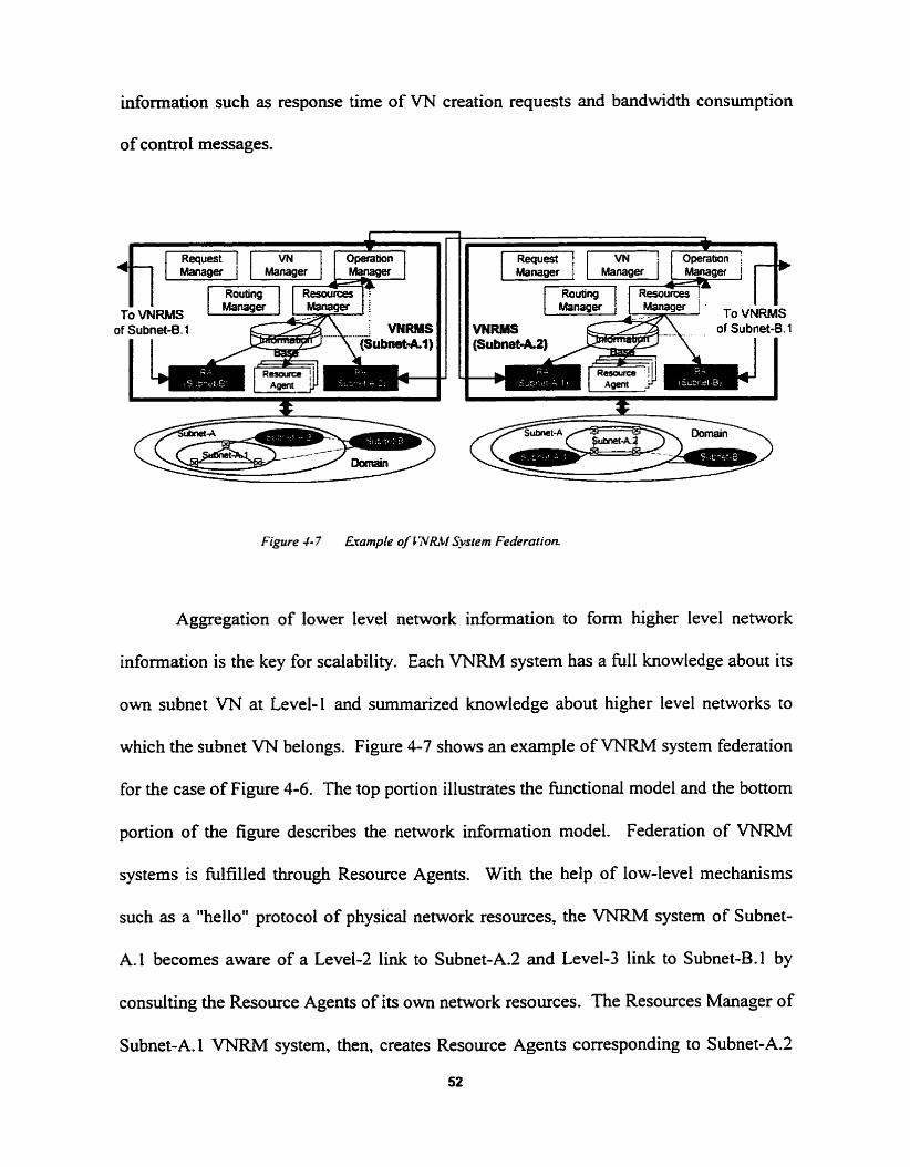
idormation such as response time of VN creation requests and bandwidth consumption
of control messages.
Figure 4- 7 fiample of CXILtf Sysrem Federarion.
Aggregation of lower level network information to form higher level network
information is the key for scaiability. Each VNRM system has a full knowledge about its
own subnet VN at Level-1 and surnmarized knowledge about higher level networks to
which the subnet VN belongs. Figure 4-7 shows an example of VNRM system federation
for the case of Figure 4-6. The top portion illustrates the functional model and the bottom
portion of the figure describes the network information model. Federation of VNRM
systems is Mfilled through Resource Agents. With the help of low-level mechanisms
such as a "hellott protocol of physical network resources, the VNRM system of Subnet-
A.1 becomes aware of a Level-2 link to Subnet-A.2 and Level-3 link to Subnet-B.1 by
consulting the Resource Agents of its own network resources. The Resources Manager of
Subnet-A. 1 VNRM system, then, creates Resource Agents corresponding to Subnet-A.2
52

for the Level-2 link, and Subnet-B for the Level-3 link. Once instantiated, a Resource
Agent that is responsible for a subnet VN interacts with the corresponding VNRM system
to collect information about the subnet VN. Note that one way of s u m ~ z h g subnet
VN information is to view the subnet VN as a switching resource. The bottom-left
portion of the figure depicts the network information known to the VNRM system of
Subnet-A. 1. VN creation decision is made based on this hierarchicaily-complete network
information and propagated to other subnet VNs involved for M e r processing.

5. Customer Control of Virtual Networks
5.1 Customization of Network Control and Management
Ultimately, VNs are created to be used by customers who provide network
services to end-users. It is up to VN customers to determine how to utilize them. Since
network control and management objectives may Vary significantly from one customer to
another, each customer may want to have full control over network control and
management functions such as routing algorithms, trac control mechanisms, and
signaiing mechanisms. Providing a few options rnay sufEce needs of some customers.
but certainly not of al1 customers.
Our approach is to support full customization of network control and
management, including control systems. architectures. algorithrns. mechanisms.
protocols, and interfaces. This capability to support full customization of network control
and management presents a soft networking environment to VN customers. Customers
can arbitrarily choose right control mechanisms and aigorithrns for their management
objectives. There is enormous space of customization of control mechanisms and
algonthms for routing, resource resewation, resource allocation, FCAPS management.
and so forth. Although not required, "open" control interfaces (such as GSMP, qGSMP,
and Ariel [6] in the ATM literature) provide a good environment to actualize full
customization of network control.
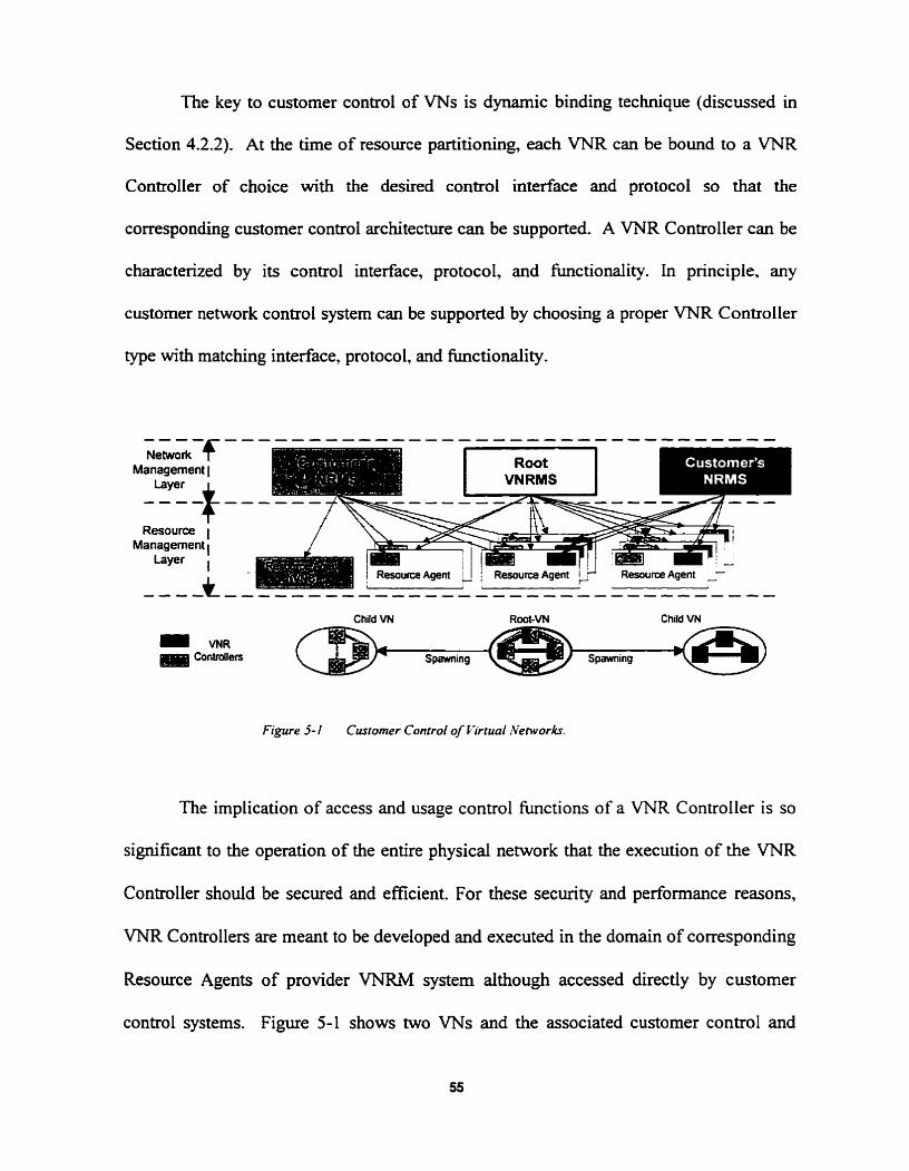
The key to custorner control of VNs is dynamic binding technique (discussed in
Section 4.2.2). At the time of resource partitioning, each VNR can be bound to a VNR
Contmller of choice with the desired control interface and protocol so that the
corresponding customer control architecture can be supported. A VNR Controller can be
characterized by its control interface, protocol, and functionality. In pnnciple. any
customer network control system can be supported by choosing a proper VNR Controller
type with matching interface, protocol, and functionality.
i e L 2 - f Management 1
Layer -+ Resource 1
Management 1 Layer I
Child VN Root-VN Child VN
Figure 5- 2-1 Customer Conrrol of Pïrrual~Verworkr.
The implication of access and usage control functions of a VNR Controller is so
significant to the operation of the entire physical network that the execution of the VNR
Controller should be secured and efficient. For these security and performance reasons,
VNR Controllers are meant to be developed and executed in the domain of corresponding
Resource Agents of provider VNRM system aithough accessed directly by custorner
control systems. Figure 5-1 shows two VNs and the associated customer control and

management systems. Note that not al1 VNR Controllers in the domain of Root-VNRM
system are directly accessed by the customer control systerns. Some VNR Controllers in
the domain of Root-VNRM system are accessed by the Resource Agent that represents a
VNC of the Root-VN (as in Figure 3-2).
5.2 Bandwidth Management
Bandwidth management is one of the most important functions of network control
and management. Performance of network services and efficiency of network resource
utilization heavily depends on the bandwidth management methcdology. In the literature
of ATM, there have been numerous proposais of how to manage bandwidth of a group of
connections efficiently for easier traffic control with better performance. Some have
proposed measurement-based bandwidth management mechanisms based on VN (or
VPN) concepts 171 [8]. Their bandwidth management mechanisms operate adaptively to
adjust capacity or bandwidth of (virtual) network resources according to network trafic
changes in non-real-tirne. In this section, we present a few dynamic bandwidth
management schemes that operate in real-time as well as in non-real-the.
Figure 5-2 depicts a classification of bandwidth management schemes that the
VNRM architecture can employ. There are two main categories, static and djmamic.
Supporting the static scheme does not require additional control mechanisms. Dynamic
bandwidth management can be M e r divided into real-time and non-real-time by
management time scale. Non-real-tirne dynamic schemes are based either on schedules
(proactive) or on measurements (reactive). When the profile of network tfic (matrix) is
56

known in advance, bandwidth allocation c m be scheduied for proactive bandwidth
management. Reactive bandwidth allocation can be dso exercised by monitoring the
measurements of network resource statuses. Both of these non-real-tune dynamic
schemes can be activated simdtaneously, but a precaution may be necessary to minimize
correlative side effects. The non-real-time dynamic schemes are supported by hard VNRs
through the client-server interactions of two layer network management systems (VNRM
systems) as described in Section 4.2.3 (number 1 1).
Bandwidih Non-Real-time Higher Management \ Measurement-based Neîwork-level
Dynamic Multiplexing
Demand-based Gain
Figure 5-2 Bandwidri; Management Classrficarion.
Altematively, real-time dynamic schemes can be employed to provide bandwidth
on a demand basis. The demand-based scheme is built on top of the soft VNR concept
(discussed in Section 3.1). When there is a comection request from an end-user, a sofi
VNR makes a request for more resource capacity to the parent VNR through the
associated VNR Controller. in contrast to the non-real-time dynamic schemes. the soft
VNR-based dynarnic scheme does not require any interactions between management
systems (VNRM systems). Rather, client-server interactions for resource capacity
allocation occur within Resource Agents in real-thne (discussed in Section 4-22).

Al1 of the dynamic bandwidth management schemes cm enable network-level
multiplexing of network traff~c. With the schedule-based scheme. a customer (client)
control system (NRM system) may request more bandwidth when needed. and release
spare bandwidth when not needed. on the basis of the timely profile of its (virtual)
network ûafEc. By multiplexing multiple such client networks into a single server
network (i.e., spawning multiple VNs out of a Root-VN), the overall bandwidth of the
server network can be shared efficientiy among the competing client networks. The
measurement-based scheme can bring better network-level multiplexing eficiency by
requesting bandwidth reactively based on utilization of network resources. Since the
measurement-based scheme is non-real-time. reactions c m take place only when certain
threshold values are met. Instant demands for more bandwidth are neglected. For this
reason, we propose the demand-based dynamic bandwidth management scheme. which
can adapt bandwidth of client network resources to instant changes of bandwidth
demands in real-time. In principle, there is no or minimal additional control overhead for
this scheme since the connection-level admission control function is merely transferred to
the network-level admission control function. With the expense of higher blocking
probability, oversubscription of resource capacity may be allowed to client VNs to
magnify network-level multiplexing gain. When there is suficient number of client VNs.
the degradation of GoS for each client VN will not be so bad.

6. Conclusion
In the beginoing of this thesis, we have presented how virtual networks can
provide a basis of a firturistic networking environment that is open. versatile. and
programmable. By adopting, extending, and generalizing virtual network concepts
proposed in the Iiterature, we have developed generic defuiitions and systematic
organizations of virtual networks and virtuai network resources. The introduction of
spawning and composition processes has enabled us to develop hierarchical layers of
virtual networks for the provision of stnichired organization of administrative and
disciplinary (virtual) network domains. Al1 of these conceptual developments of virtual
networks have been based on a fundamental assumption that physicai network resources
can be abstracted to vimiai network resources for easy and efficient partitioning.
A major portion of the thesis has been dedicated to the development of a
management architecture for virtual networks and their resources. Due to a broad range
of research areas and issues associated with the control and management of network
resources, the scope of our work has been circurnscribed to a high-level design of the
virtual network resources management architecture. As such, the focus of our work has
been on the integration and consolidation of diverse concepts and principles frorn various
contexts of networking into a single management framework in the context of virtual
networks.
Finally, customization of network control and bandwidth management have been
discussed in the thesis. By the introduction of dynamic binding and Root-VN, we have
59

been able to achieve system-level customization of network control and management with
direct access to network resources for fiil1 control functionaiity and low latency of the
control hctions. The concepts of soft resource and demand-based dynamic capacity
allocation have enabled efficient network-level rndtiplexing of network trafftc.
Throughout the development process of the vimial network resources
management architecture, we have used a "top-down" approach and intentionally
excluded details of low-level mechanisms and protocols for technology independence and
separate development. Further research on the development of technology-specific
architectures is planned in our lab, NAL (Network Architecture Lab), at the University of
Toronto. in parallel, more research efforts will be put into the issue of generic network
resource representation in the context of virtual networks.

References
[ 1 ] ITU-T Recornmendation 1.2 1 1. "B-ISDN Service Aspects," Geneva 1 99 1.
[2] ITU-T Recommendation L3 1 1. "B-ISDN General Network Aspects." Geneva 199 1.
[3] R. Braden, D. Clark, and S. Shenker, "htegrated Services in the Intemet
Architecture: an O v e ~ e w , " intemet WC- 1633, Jdy 1994.
[4] S. Fotedar, M. Gerla, P. Crocetti, and L. Fra- "ATM Virtual Pnvate Networks."
Communications of the ACM, vol. 38, no. 2, pp. 10 1-109, February 1995.
[SI A. Farago, S. Blaabjerg, L. Ast, G. Gordos, and T. Henk, "A New Degree of
Freedom in ATM Network Dimensioning: Optimizing the Logical Configuration," IEEE
JSAC, vol. 13, no. 7, pp. 1 199- 1206, September 1995.
[6] J.E. van der Merwe and LM. Leslie, "Switchlets and Dynamic Vimial ATM
Networks," IM '97, pp. 355-368, May 1997.
[7] M.C. Chan, A. A. Lazar, and R. Stadler, "Customer Management and Control of
Broadband VPN Services," IM '97, pp. 301 -3 14, May 1997.
[8] 2. Dziong, Y. Xiong, and L. Mason, "Virtual Network Concept and Its
Applications for Resource Management in ATM Based Networks," Broadband
Communications '96, Montreai, Canada, April23-25, 1996.
[9] G. Woodmff, N. Perinpanathan, F. Chang. P. Appanna, and A. Leon-Garcia.
"ATM Network Resources Management using Layer and Virtual Network Concepts," IM
'97, May 1997.

[IO] R. Guérin, H. Ahmadi, and M. Naghshineh, "Equivalent capacity and its
application to bandwidth allocation in hi&-speed networks," E E E Journal on Selected
Areas in Communications, vol. 9, no. 7, pp. 968-98 1, September 199 1.
[ I l ] A. 1. Elwdid and D. Mitra, "Eflective bandwidth of general Markovian t - I C
sources and admission control of high speed networks." IEEUACM Transactions on
Networking, vol. 1, no. 3, pp. 329-343, June 1993.
[12] TINA-C Document No. TB - MDC.0 18-1 -0-94. "Overail Concepts and Principles
of TINA," TINA-C, Febniary 1995.
[13] ITW-T Recommendation G.805 (Dr&), "Genenc Functional Architecture of
Transport Network." Geneva, 1 992.
[ 141 ATMF Document: af-pnni-0055.000, "Private Network-Network Interface
Specification Version 1 .O (PNNI 1 .O)," ATM Forum, 1996.
[ 151 ITU-T Recommendation M.30 10. "Principles for a Telecommunications
Management Network," Geneva, October 1 992.
[16] Edited by Salah Aidarous and Thomas Plevyak, Telecornrnirnicafions Yemork
Management into the 2 1" Century : Techniques, Sfandardr. Technologies. and
Applications, IEEE Press, New York, 1993.
[ 1 71 TINA-C Document No. T B N S .OO52.0-94, "Engineering Modelling Concepts
(DPE Architecture)," TINA-C, December 1 994.
[18] W. Barr, T. Boyd, and Y. houe, "The TTNA initiative," IEEE Communications
Magazine, pp. 70-76, March 1993.
[19] T. F. Mowbray and R. Zahavi, The essential CORBA: System Integration Using
Distributed Objects, Wiley, New York, 1995.
62

[20] A. Lazar and K. S. Lirn, "Realizing a Fondation for Programrnability of A M
Networks with the Binding Architecture," IEEE Journal on Selected Areas in
Communication, vol. 14, September 1996.
[21] S. Rooney, "The Hollowman, an innovative ATM control architecture." iM '97.
May 1997.
[22] Nishant Perinpanathan, "Modeling and Speczjicaiion of a TINA Cornpliant A TM
NRM Architecture," M.A.Sc. Thesis, Department of Electncal and Computer
Engineering, University of Toronto. 1996.
[23] Prakash D. Appanna, "Object Orienied Modeling of Rouring wiihin a Network
Resowce Mcnagemenf Scherne." M.A.Sc. Thesis, Department of Electrical and Computer
Engineering, University of Toronto, 1996.
[24] Frank Y.H. Chang, "The Developmenf and Specifcation of an ATM Network
Resource Management Information Model," MASc. Thesis, Department of Electrical
and Computer Engineering, University of Toronto, 1996.
[25] ITU-T Recommendation G.803, "Architectures of Transport Networks Based on
the Synchronous Digital Hierarchy (SDH)," June 1992.
[26] ITU-T Recommendation M.3 100, "Generic Network Information Model." 1992.
[27] OSI, LS.0, 10040 Systems Management Overview. 199 1.
[28] ITU-T Recommendation X.70 1, "Systems Management Overview," Jan. 1992.
[29] ITU-T Recommendation M.3000, Overview of TMN Recommendations, 1994.
[30] ISOAEC JTC 1/SC2 1 10746- 1 / ITU-T Draft Recommendation X.90 1. "Basic
Reference Model of Open Distributed Processing - Part 1: Overview and Guide to Use,"
November 1992.

[31] ISO/IEC JTCl/SC2110746-2.2 / ITU-T Draft Recommendation X.902, "Basic
Reference Model of Open Distributed Processing - Part 2: Descriptive Model," November
1992.
[32] ISO/IEC JTCl/SC21 10746-3 1 ITU-T Dmft Recommendation X.903. "Basic
Reference Model of Open Distributed Processing - Part 3: Prescriptive Model."
November 1 992.
[33] J. Hyman, A. Lazar, and G. Pacifici, "Real-time scheduling with quality of service
constraints," EEE Journal on Selected Areas in Communications, September 199 1.
[34] J. Hyman, A. Lazar, and G. Pacifici, "VC, VP and VN Resource Assignment
Strategies for Broadband Networks," Proceedings of the 4h International Workshop on
Network and Operating System Support for Digital Audio and Video, vol. 846. Springer-
Verlag, 1994.
[35] R. Doverspike, et al., 'Tuetwork Management Research in ATDNet." IEEE
Network, July/August 1 996.
[36] Mischa Schwartz, Broadband Integraied Nehwrh, Prentice Hall, New York.
1996.
[37] Andrew Do-Sung Jun, Alberto Leon-Garcia, and Muhammad laseemuddin.
"Vimial Networks: A Divide-and-Conquer Approach to Network Resources
Management," Slide Presentation at OpenSig Fa11 '97 Workshop, Columbia University.
October 1997.
[38] William Stailings, SNMP. SNMPV2, and CMIP: The Practicul Guide to Nenvork-
Management Standarcis, Addison- Wesley, New York, 1 993.

[39] P. Newman, et al., "GSMP Protocol Specification." Intemet RFC-1987. August
1996.
[40] P. Newman, W. Edwards, R. Hinden, E. Hoffian. F. Liaw, T. Lyon, and G.
Minshall, "Ipsilon's General Switch Management Protocol Specification," Intemet Dr&.
October 1997.
[41] C. Adam, A. Lazar, and M. Nandikesan, "QOS Extensions to GSMP," OPENSIG-
DRAFT: CU/CTR/TR 47 1-97-05. Columbia University. Apnl 1997.
[42] ITU-T Recommendation 4.293 1 (Drafi), "Broadband Integrated Service Digital
Network (B-ISDN) Digital Subscnber Signalling Systems No. 2, User-Network interface
layer 3 specification for basic calVconnecûon control," 1994.
[43] Travis Russell, Signaling System #7, McGraw-Hill, New York, 1 995.
[44] ATMF Document, "ATM User-Network Interface Specification," Version 3.1.
ATM Forum. 1994.

IMAGE EVALUATION TEST TARGET (QA-3)
APPLIED & IMAGE. lnc 1653 East Main Street - -. - Rochester. NY 14609 USA -- --= Phone: 71 W482-0300 -- --= Fax: 71 6/2ûû-5989