Embed Size (px)
Citation preview

NOTE TO USERS
This reproduction is the best copy available.

Design and Implementation of an Agent-based
Architecture for QoS Management
by
Yajin Xin, B.Sc.
A thesis submitted to
the Faculty of Graduate Studies ruid Research
in partial fulfillment of
the requirements for the degree of
Master of Computer Science
Ottawa-Carleton Institute for Computer Science
School of Computer Science
Faculty of Science
Carleton University
Ottawa, Ontario, Canada
1 6/O9/2ûûû O Copyright
2000, Yajin Xin
National Library 1*1 of Canada Bibliothèque nationale du Canada
Acquisitions and Acquisitions et Bibliographie Seivices sewices bibliographiques 395 Wellington Slreet 395, rue Wellington Ottawa ON K I A O N 4 ûüawaON K 1 A W Canada Canada
The author has granted a non- exclusive licence allowing the National Libraiy of Canada to reproduce, loan, distribute or sell copies of this thesis in microform, paper or electronic formats.
The author retains ownership of the copyright in this thesis. Neither the thesis nor substantial extracts fiom it may be printed or othemke reproduced without the author' s permission.
L'auteur a accordé une licence non exclusive permettant a la Bibliothèque nationale du Canada de reproduire, prêter, distribuer ou vendre des copies de cette thèse sous la forme de microfiche/film, de reproduction sur papier ou sur format électronique.
L'auteur conserve la propriété du droit d'auteur qui protège cette thèse. Ni la thése ni des extraits substantiels de celle-ci ne doivent être Unprimés ou autrement reproduits sans son autorisation.
Abstract
With the rapid growth of network multimedia applications such as video
conferencing, multimedia communications, more and more network data transmissions
require Quaiity of Service (QoS) management mechanisms. In order to guarantee QoS to
individual user sessions, elaborate QoS management hinctions such as QoS routing,
resource reservation. QoS adaptation are required. h ihis thesis, we propose an
arc hi tecture of route serven to handle these functions integrally on behdf of individual
routers in a network domain. In the architecture, the establishment and maintenance of a
QoS session follow related and de-coupled phases. The functionality of the route senier is
implemented using the combination of agent and active network technologies. That is, the
CO-operative stationary and mobile agents are deployed to perform the QoS management
tasks. such as QoS negotiation. routing, resource reservation. adaptation, and network
data coilecring, etc. We will discuss the QoS requirements of distributed multimedia
applications, and various management issues involved in the establishment and
maintenance of a QoS session. Also. we will investigate the mobile agent and active
network technologies, and their potential roles in QoS management. Baxd on these
researches. we will describe Our agent-based QoS management architecture which is
devcloped on a cooperative mobile agent platform. The architecture is designed to
provide QoS management and negotiation services for multimedia applications that needs
QoS support.

Acknowledgement
The completion of this thesis has k e n possible due to the academic and moral
support that I have received in the past one year and more from Professor Ahmed
Kannouch. His countless valuable guidance, advice, encouragement and patience have
made the progression of this research a possible task. It has been an honor and privilege
to have had the opportunity to carry out research under his supervision.
I would also like to thank the professors of School of Computer Science of
Carleton University, who provided me with al1 the knowledge 1 required through ai1 the
stages of my master study.
Going back to the origins, 1 should express my boundless gratitude and special
thanks to rny farnily: my husband and my parents, whose consistent encouragement,
suppon and patience have enabled me to transform my education goals into a reality.
Finaily, thanks to d l the colteagues of the Multimedia information and Mobile
Agent Research Lab, who have given me continuous assistance to transcend rnany of the
obstacles that 1 fiiced in the joumey of the research.
Table of Contents
... .......................................................................................................... Abstract iii
.......................................................................................... Ac know ledgement iv
................................................................. CHAPTER 1 INTRODUCTION 1 1.1 ProbIem Overview ................................................................................................. 1 1 -2 Motivations ............................................................................................................ 3 1.3 Thesis Contributions .............................................................................................. 7 1.4 Thesis OutIine ........................................................................................................ 9
CHAPTER 2 OVERVIEW OF QoS MANAGEMENT FOR ...................................... DISTRIB UTED MULTIMEDIA APPLICATION 1 0
2.1 QoS Parameters and Parameter Mapping ............................................................ 11 ...................................................................................... 2.2 QoS Management Issues 13
2.3 QoS-basedRouting .............................................................................................. 16 2.4 ReSerVation Protocol (RSVP) operationai mode1 ............................................... 19
................................................................. 2.5 Reliable Multimedia Communication 2 2 .................................................................... 1.6 Related Works on QoS Architecture 24
............................. CHAPTER 3 IMPLEMENTATION TECHNOLOGIES 28 3.1 Mobile Agent Technologies ........................ .... ............................................ 28
................................................................................................................. 3.1.1 Whar is an agent? 29 3 . 1 . 2 The gencral advanrages of using agent ................................................................................ 30
...................................................................................... 3 Mobile ugent management systern s. 33 ................................................................................ 3.2 Active Network Technology 34
3.2.1 What is active nenvork? ........................................................................................................ 34 ...................................................................................... 3-27 Two upproaches ro active nenvorkr 36 ....................................................................... . 3.3 Mobile Agent vs Active Network 38
CHAPTER 4 OVERVIEW OF THE ARCHITECTURE AND ............................................................. IMPLEMENTATION PLATFORM 40
4.1 Overview of the Architecture ............................................................................... 40 1.2 Funher Advantages of Route Server Architecture .......................................... 47
....................... 4.3 Using Mobile Agent Technology to Irnplement the Architecture 49 ...................................................... 1.4 The Co-operative Agents in the Architecture 51
1.5 SHIP-MAI Mobile Agent Platform ...................................................................... 56 4.5.1 Piarformcomponents .................................. .... ............................................................. 56
................................................................ ....................... 4 5 . 2 SHIP-MAI agent life cycle ...... 60 .................... 4.5.3 SHIP-MAI orveral1 architectirre .. ......... .. .................................................. 63
................................ 4.6 Building Our QoS Architecture on Top of S m - M A I 6 5
CHAPTER 5 DESIGN AND IMPLEMENTATION ................................... 68 1 Negotiation Phase ................................................................................................ 68
1 . Negotiarion between sender and receiver .......................................................................... 69 ........................................................................................ 5.1.2 Negotiation wirh the router server 77
................................................................................................................................. 5.1.3 QoS request 83 5.2 Path information Database and Routing Algorithm ............................................ 84
.................................................................................................. 2 . 1 Strucrrtre and data of PIDB 85 ................................................................................... 5.2.2 The ejjiciency consideration of PIDB 88
5.2.3 Path selecrion algoritlm ....................................................................................................... 89 5.3 Reservation Phase .............................................................................................. 91
3 1 Why can 't we make use of RSVP? ........................................................................................ 93 5.32 Design of the resource reservation approaches in oirr urchitecrwe .................................... 94 5.3.3 Format of reservation messages ....................................................................................... 99
..................................................................................................... 5.3.4 Reservarion refreshmenr 101 5.4 QoS Adaptation .................................................................................................. 103
........................................................................ 5.5 Sample of Expenmentai Results 105
CHAPTER 6 CONCLUSION AND FUTURE WORK ............................. 113 6.1 Summary ................................................................................................................ 113 6.2 Future Work and Suggestions ............................................................................... 114
References ................................................................................................... 117
List of Figures
Figure 1 . RSVP operationai mode1 ................................................................................ 2 1 Figure 2 . Overview of QoS management ......................................................................... -41 Figure 3 . Overview of the architecture .............................................................................. 42 Figure 4 . Sendedreceiver negotiation and routing ........................................................... -44 Figure 5 . Route server performs reservation .................................................................... 44 Figure 6 . SHIP-MAI platform mode1 ............................................................................... 56 Figure 7 . Agent life cycle ................................................................................................. 62 Figure 8 . Route semer mode1 on SHIP-MAI .................................................................... 66 Figure 9 . Architecture layout at agent platform level ....................................................... 66 . . Figure 10 . Class diagram of negotiation agent ........................................................... 7 0 Figure 1 1 . Mobile agents conduct the sender and receiver negotiation ............................ 71 Figure 12 . Sequence diagram of senderlreceiver negotiation ........................................... 72 Figure 13 . Sequence diagram of the routing process ........................................................ 79 Figure 14 . Class diagram of QoS management agents ...................................................... 81 Figure 15 . E-R diagram of P D B ....................................................................................... 85 Figure 16 . PiDB entities and attributes ............................................................................. 87 Figure 17 . Sequence diagram of reservation phase .................... ... .............................. 92 Figure 1 8 . Discrete approach of resource reservation ................................................. 9 6 Figure 19 . Integrated approach of resource reservation .................................................... 98 Figure 20 . Activity diagrarn of QoS adaptation .............................................................. 105
................................................................. Figure 3 1 . Sample network domain topology 106 Figure 22 . Receiver's mnning status ............................................................................... 107 Figure 23 . Sender's mnning status ................................................................................. 107 Figure 24 . Route server's running status ......................................................................... 108 Figure 35 . Conversation between negotiation agents ................................................. 109
.............................................................. Figure 26 . Route server processes QoS request 1 10 Figure 27 . Routing agent performs path selection process ............................................ 1 Il Figure 28 . Housekeeper agent mnning status ................................................................ 1 12 Figure 29 . A sarnple of reservation agent ..................................................................... 1 12
vii
CHAPTER 1
INTRODUCTION
1.1 Pro blem Overview
The Intemet is the rnost rapidly growing services. It is not only becoming an
indispensable media for human interaction. but also is the vehicle for the fast emerging
network integrated services. such as. video conferencing. and distributed multimedia
applications. etc. The content of such network applications has specific requirements of
communication qualities. such as bandwidth allocated for individual connection. end-to-
end delay. jitter. etc. As a result, Quality of Service (QoS) has been a very active topic in
data network communication research and development in recent years. QoS is a set of
service requirements to be met by the network while transponing a flow. Generally, It
refers [O the capability of a network to provide better service. such as dedicated
bandwidth. controlled jitter and latency. and improved loss characteristics. to selected
network traffic over various network transmission technologies. like Frarne Relay. ATM.
Ethernet, SONET. and iP-routed networks. In other words, QoS is the idea that network
communication qudities, such as transmission rates. error rates. and average packet
delay, etc.. cm be measured. irnproved, and. to some extent. guaranteed in advance.
On the Internet. QoS is of particular concem for the continuous tmsmission of
high-bandwidth video and multimedia information that requires sophisticated resource
management. But the most important deficiency of the present packet-switching networks
and of their protocols (P family) falls short of capabilities for delivering the kind of
reliability and performance guarantees. The same problem peaists for broadband uitemet
that has becarne the base for the transmission of multimedia information. Despite the high
throughput rate of the broadband. there are still no guarantees for the relevant QoS
parameten [ 131. Therefore, today's packet-switching networks providing best-effort
service are no longer adequate for network multimedia applications. To cope with this
situation. there have been continuous efforts made on the application level. The design of
multimedia applications that need specific performance requirements may allow users to
specify the necessary QoS parameters. However, on the network level, transmitting such
QoS-sensitive content dependably is difficult in public networks. because hardwired
rrsources management mechanisms are not sufficient. Therefore, new service
architectures are required to provide solutions to this problem, especially for enterprise
applications. Businesses will not place their mission-critical data. voice. and multimedia
applications ont0 public [P networks until they receive secure. predictable. measurable.
and guaranteed service. They need a kind of virtud private networks [20] in which the
QoS and security issues can be rnanaged centrally to support business-critical
applications.
In this thesis. we propose an end-to-end approach of integrated QoS management.
including QoS negotiation, end-to-end path management. QoS routing. resource
reservation. and QoS adaptation. for intemet services and real-time applications with a
focus on network multimedia information applications. over packet-switched network.
The purpose of the design is. first, to provide users and network multimedia service
providers ri mechanism to specify the desired QoS requirements according to the
multimedia application specification, and then, aiiocate and maintain enough network
resources to meet the requirements. The proposed architecture manages the network
resources in overall such that the reliable QoS transmission of the data packets c m be
flexibly guaranteed.
Motivations
The main motivations of our design are the drawbacks of current QoS
management approach of today's packet-switching network. in w hich individuai stand-
done routers perform most of data transmission routing and other network management
tasks. While this approach might scale adequately and be fault tolerant in providing best
effort service. it may not be an efficient solution to integraied services that have
introduced new QoS requirements. These requirements have consequently introduced
substantial extra burden on the stand-alone routers, even stretch the traditional QoS
approach to its limit. People may think that to rstablish an end-to-end path with a specific
QoS. the additional work of the routers dong the path is just to reserve resources
(bandwidth. buffers) for the set of packets of the tlow. But the fact is. before the
reservation cm be made and while the session is active, there are many other problems
for each router to solve. We can identify the main problems as follows:
First of d l . for certain network applications. the network needs to provide every
individual user session an end-to-end path with guaranteed QoS. To meet this
requirement. QoS based roiiting is needed. However, compared to the well known
shortest path routing aigorithms used by routen for the ordinary best effort data
transmission, QoS based routing algonthms need to deal with more constraints [ 11 which
include bandwidth availability, end-to-end delay, delay jitter, and buffer space bounds,
etc. In the meanwhile, besides considering these constraints, another objective of the QoS
routing is to select the path that leads to high overall resource efficiency. To meet these
routing requirements. much more processing power is required on each router.
Second, network is a dynamically changing environment where hardware failure.
service maifunctions, and user misbehriviors occur from time to time. Thereforc, the
network dynarnic information, such as the current state of system components, path
performance data. and reliability measures, needs to be stored and managed for QoS
conccm. especially for real-tirne applications that have very stringent requirements on
network delay and friult tolerance. In the event of QoS requirement violation when a
currently used path becomes no longer useful, the network has to quickly re-route the
tlow and interact with the reservation protocol to avoid the performance of corresponding
real-tirne application being noticeably affected [ l . 101. However the existing network
management systems cannot meet this requirement. In the current systems. such as
SNMP architecture. there is no automated mechanism that periodically aggregates data
from routers to produce information about "ready to use" paths. In addition, such systems
do not interact with the reservation protocols. Therefore, when a QoS path becomes
unusable. the application that is using it would have to re-invoke the reservation protocol
to rstablish a new path as replacement [Il. Such "emergency-response" mechanism is too
far away from the requirements of real-time applications.
Third problem is that most of the work to date has been primarily concerned with
setting up immediate reservation, that is, the QoS takes effect imrnediateiy and remains
in effect for an indefinite duration. There are more and more network applications with
the requirement of making advance reservation of a QoS that will take effect in the future
[8]. Examples of such applications are videoconference applications and remote lectures.
For these applications, it is important to make sure, in advance, that the resources will be
available at the desired time. T-RSVP proposed in [?] is the augmentation of RSVP,
which takes the session start time and duration into consideration. But by only using this
straightforward modification of RSVP, the reservation States need to be maintained in the
router until the session terminates. With the growing of such applications, the rnemory
burdrn produced by the amount of state stored in the routers cannot be ignored [8].
Moreover. this approach needs the sending and receiving applications to be active during
the entire advance reservation time, which is not redistic in most cases.
Furthemore. it is desirable to use different QoS routing algorithms under
different network conditions. The research [3] shows that routing algorithm that gives
preference to limiting the hop count performs better when the network load is heavy.
while the algorithm that gives preference to balancing the network load performs better
when the network load is light. On the other hand, from the application point of view.
di fferent traffics. e g , traffics with bandwidth guarantee. vs. traffics with deiay guxantee.
also expect to be treated with different routing algorithms [4]. Therefore. to take full
advantage of the nerwork resources for the best network performance. and to sufficiently
support various applications, the routers need to "remember" dl those algorithrns. and
"know" when to use each one of them. To have such flexibility also requires more
cornputation at each router.
In summary, al1 these requirements demand new processing power and therefore
produce very heavy-weighted routers, which, in tum. easily become the bottleneck of
network performance [ I l . And, if every router had to (could) satisfy al1 these
requirernents. the processing overhead would become a major concern. It would be ideal
to have the routers concentrate on forwarding packets, and have another system handle
the complicated QoS routing and management tasks.
This thesis is devoted to propose a solution to ddress the above problems using a
sever and agent based architecture to take over the QoS management related tasks from
individuai routers and the resource reservation responsibilities from network applications.
Specifically, we propose to use a Roiite Semer to be in charge of al1 the QoS management
rehted issues, and use the combination of agent and active nenvork technology to support
and realize the functionality of the Route Server. The idea of Router Server is gained and
derived from the knowledge and wisdom of some other researches.
The idea of Roiite Semer ( R S ) was initially introduced to take over the tasks of
routing updates for Intemet Service Provider (ISP) routers [2]. This is in order to
îicilitate md simplify inter-domain routing among ISPs' routers chat share a Network
Access Point (NAP). RS is deployed at the Internet interconnection points to first gather
routing information from ISP routers. then process the information based on the ISP's
routing policy. and finally pass the processed routing information to each ISP router.
Without the RS. the ISP routers have to establish full-mesh BGP peer sessions among
thernselves in order to exchange routing information. if the nurnber of ISPs at a NAP is
large. a sizable load could be placed on each router to maintain the required peering
sessions and process the needed routing information. With the presence of RS, each ISP
only needs to peer with one RS. instead of rnainiaining peer sessions with ail other ISPs
at the NAP. Thus, RS greatly reduces the routing processing load on the ISP routes at a
NAP. And by supplying ISP routers with one, and only one route to each destination. the
RS substantially improves peer routers' ability to handle full Internet routing.
This project gives us a hint that the route server provides flexibility in terms of
adding new mechanisms or techniques to routing. So why don? we think about making
use of Route Server to perform QoS management tasks? Several research projects have
done some work with this idea. That is, for a network domain. they deploy a server to
perform QoS routing or other QoS management on behalf of the individual routers in the
domain. SAAM project [ l ] proposes a route server architecture to perform QoS routing.
The Advance Reservation Architecture [SI uses an advance reservation server to handle
d l the advance reservation requests on behalf of routers. We will describe these related
works in the following chapter.
Thesis Contributions
This thesis aims to make several contributions. The k t contribution is the design
of a Route Server QoS management paradigm and the initial implementation of the
architecture. The structure of the architecture is based on SAAM project. The functions
of Route Server include negotiation, QoS routing. reservation and adaptation. The
establishment and maintenance of a QoS session follow de-coupled and related phases.
We implement the architecture using mobile agent technology, that is, using dedicated
cooperative agents to fulfill the various functions of the route server. We also design the
structure of the path information database for each route server to maintain the path
information of its domain. For the QoS routing part, we develop a path selection
algorithm that selects the shortest feasible path while trying to balance the network load.
The second contribution is made in the mobile agent and active network research
area. Our architecture is built on SHIP-MAI platform as an experirnental agent
application. SHIP-MAI is a mobile agent platform that is designed and implemented in
Our research lab. We propose this architecture to exploit the role of mobile agent in QoS.
Our architecture also rnakes use of the idea of active network. That is, the agents that
perform the functions of the route server operate from application layer, such as
performing the negotiation on behalf of the users. down to the network layer. such as
making the actual reservation with routen.
The third contribution is made for network multimedia applications in two
aspects. First. for a multimedia database to transmit data to a user. it always needs to
negotiate with the user about the transmission cnteria before the actud data is delivered.
Our architecture tends to provide the developers and users of such applications an
automatic way to go through the negotiation. They only need to have an application
profile or system profile. then the negotiation agents will get the information frorn the
profiles and perforrn the negotiation on behaif of the applications and their users. Second.
to reserve the resources using RSVP, it is the sender and receiver's responsibility to send
certain messages going through the network to find the path and reserve the resources.
Our architecture uses the route server to take over these responsibilities from the sender
and receiver. We believe it is a reasonable and helphil way especidly for the applications
that nred advance reservations. They just need to send the requests to the route server as
advmce reservation, once they get the confirmation from the route server, they c m be
sure that the required resources will be available at their desired time.
The remainder of this thesis is organized as follows. The next chapter is an
overview on the QoS related issues of multimedia applications, which includes QoS
parameters, QoS management steps. such as routing, reservation and adaptation. Also. in
this chapter. we will introduce some related works that give us a lot of inspiration for Our
research. Chapter 3 discusses about the implementation technologies of our architecture,
the mobile agent and active network technologies. For each one, we will explain the
principle, the characteristics, the advantages, and the realization approaches. etc. Chapier
1 and 5 are about the design and implementation of our QoS management architecture.
First. chapter 4 presents the overview of the architecture, the functiondity of its
components. and we also will describe. in this chapter. the key points of the mobile agent
platfom on which we setup Our architecture. Then, chapter 5 explains the design and
implementation by going through the phases of how a QoS session is established and
maintained. Also, we will present some sample mnning results of the system. The final
chûpter sumarizes the thesis and presents the issues that expect further work.
CHAPTER 2
OVERVIEW OF QoS MANAGEMENT FOR
DISTRIBUTED MULTIMEDIA APPLICATION
As we pointed in the first chapter. Our design is to provide QoS management to
lntemet services with focus on distributed multimedia applications. The examples of
network distnbuted multimedia application are: tele-conferencing, remote lecturing,
video-on-demand, and news-on-demand. etc. The information of multimedia application
composes of various mono-media, such as text, still image. audio sequence and video
sequence. Because of this property. the uansrnission of distributed multimedia
information requires new quality of services. Such new quality is characterized by
transfemng one or more strearns of coniinuous media data, ç.g., video or audio, and by
managing various media at the same timr, which implies suingent perfomûnce
requirernents in terms of throughput, delay, jitter, and loss rate. These requirements are
much more severe than that of traditional applications on the underlying involved
entities. e.g.. network. end systems of sender and receiver, and hence generate new
management requirements with respect to the QoS. A possible definition of QoS in
multimedia application context is: "QoS represents the set of those quantitative and
qualitative characteristics of a distributed multimedia system necessary to achieve the
required functionality of an application" [ I 11. in this chapter. we describe the QoS
requirements and management issues of distributed multimedia applications and the
deploying technologies that are engaged to achieve the QoS requirements.
2.1 QoS Parameters and Parameter Mapping
QoS provides a good criterion to express multimedia applications requirements by
the so-cdled QoS parameters. Different system level. different entities invoived in the
data transmission have apparently distinct set of parameters to represent their QoS
requirements. Hence, the QoS panmeters cm be categorized according to different level.
di fferent entities. and different aspects:
User perceptual parameters, such as image clarity. audio quality. video color
depth, and presentation delay, etc.;
Application data format parameten. such as compression scheme. inter-
stream synchronization, frarne rate. and frame size, etc.;
Network perforntunce parameters, suc h as transmission throughput. delay ,
jitter. error rate, and loss nte, etc.;
End-system performance parameters, such as openting systems. bus
bandwidth. memory space, CPU. and UO devices. etc.;
Cost related purameters. such as copyright charges. different charge for
different transmission quality, etc.
In the whole communication architecture, different entities and components, i.e.,
sender, receiver, network protocols, and various devices, require distinct parameters that
only need to "make sense" to themselves. This brings out an important issue of QoS
parameter mupping. QoS parameter mapping process is the translation between
correspondent QoS representations of different entities or at different system levels for
identicai services. QoS mapping allows every concemed system level or entity to express.
handle and menage the rneaningful parameter representations. For exarnpie. mapping
frame rate into throughput is necessary to allow the network to support the service
requested by the user. At the beginning of the establishment of a new QoS session, the
usrrs specify their QoS requirements in terms that are farniliar to him/her using the user
perceptual parameters. These user-level parameters must be translated into the
corresponding intemal QoS parameter values of service provider's application. Then. to
üchieve the desired QoS, the QoS parameters nerd to be further translated into the
network and end-systern sensible terms, in which the translation involves the mapping of
QoS parameters into certain amounts of resources of system components, such as buffers.
CPU and bandwidth. To perform the pararneter translation, there should be. in the QoS
management system, a panmeter mapping information base and a mapping function at
every translating point between different levels and different entities. In the thesis, we
won't go very deep in this topic, but we think it wonh a comprehensive and profound
research. For more information on QoS pararneter mapping, refer to [16. 171.
QoS Management Issues
In order to support the desired QoS requirements of multimedia applications, QoS
management is essential. A QoS session of the multimedia applications c m be multi-
point multicast session, like videoconference. It also cm be point-to-point unicast
session, like online multimedia database visit, video-on-demand or news-on-demand. The
ultimate aim of our QoS management architecture is to support various kinds network
multimedia applications. But in this thesis, we only consider the management issues of
the point-to-point session of multimedia applications. This is the first step towards our
ultimate goal. In the future. we cm üdd other necessary functions for support multicast
ruid user interaction, etc.
In most of the multimedia applications. the multimedia objects are stored at a
server (sendrr of the transmission) and played back at the clients' sites (receiver of the
transmission). A point-to-point session refen to the data Bow with certain QoS
specification sent from the depository of multimedia source to a particular remote
destination. The whole procedure of QoS management for a session cm be defined as a
serial of activities from prior to the session starts till the session terminates. which
includes: QoS negotiation, QoS mapping, policy control. QoS routing, resource
reservation. QoS monitoring, QoS adaptation, and so on. To fulfill these relatively big
activities, there are more detailed technical functions CO achieve the QoS at each network
lrvel and system component, such as QoS panmeter specification [16]. priority-
basedkustom-baseweighted-fair-based packet schcduling [ 181. rniddlewarelhardware
support for multimedia data transmission, end-host operating system issues. and so on.
Every topic deserves a deep research. In this thesis, we'll focus on an overall QoS
management architecture and the high level working mechanism from the architecture
point of view. In Our QoS management architecture. we consider a typical scenario of
QoS management involving the following steps:
( I ) Receiver starts up
A user (receiver of the multimedia data) asks for a multimedia service from the
source of multimedia application. The user specifies the desired time and desired QoS in
the request.
(2) Sender and receiver negotiation
For most of the multimedia applications, the multimedia service is not fixed. and
either the cost of different QoS. The cost is an important parameter in QoS negotiation.
without cost constraints. the receiver will always ask for the best QoS available.
Therefore. the receiver need to select an appropriate QoS based on hisher hardware and
network capabilities and his willingness-to-pay so as to rnaxirnize hisher net benefit.
Then. the multimedia service provider (sender of the multimedia data) and the receiver
will negotirite to find an agreement on the required value of QoS parameters and the
price. If the negotiation succeeds, it means both end-systems, the sender and the receiver,
can support the agreed upon QoS requirements. Othenvise, no further steps are needed.
(3) QoS routing (negotiation with network)
If the negotiation between the sender and receiver succeeds. it needs to further the
negotiation with the network to see if the current network condition cm satisfy the
requirements. The network find this by performing the QoS routing to allocate an end-to-
end path that can support the requirements; If the result is positive, it will proceed to the
next step. Otherwise, the sender and receiver should be notified. and they would to re-
negotiate either to degrade the QoS requirements or just terminate.
(4) Resou rce reservation
After the network allocates the end-to-end path that c m support the QoS, it needs
to reserve the actual resources with the end-systems and routers dong the path to make
sure the desired QoS is practically supponed when the session is activated.
(5) QoS monitoring and adaptation
This issue is addressed to the reliability of multimedia communication. During the
data transmission. QoS management system needs to monitor the services prornised to
provide. When the measured value of a QoS parameter does not meet the agreed one.
appropriate adaptation actions should be taken to react to the changes of the environment
in order to support the initidly agreed QoS. The role of QoS adaptation is to maintain, as
far as possible. the QoS agreed during the negotiation phase. The adaptation actions
includr: QoS re-routing or picking up backup channel, making the new reservation. and
directing the data packets to the new route.
(6) Termination
When the session is end, the reserved resources wilI be released. Then the QoS
management completes its mission.
Now. we discuss some major issues of these steps.
QoS- based Routing
QoS-based routing is the routing mechanism under which paths for fiows are
drtermined based on the knowledge of resource availability in the network as well as the
QoS requirement of flows [23j. Current routing protocols deployed in today's Internet.
cg. OSPF. RIP, are focused on connectivity and typicdly supports only one type of
datagram service called "best effort". They use "shonest path routing". which is
optimized for a single cost metnc. administrative weight or hop count. These routing
protocols route the traffic using the current shortest path to a destination. Altemate paths
with acceptable but non-optimal cost can not be used. QoS-based routing must extend the
current routing paradigm by considering additionai routing metrics, such as delay, and
rivaileble bandwidth, Ioss rate, etc.
Ir is important to understand the difference between QoS-based routing and
resourcr reservation. While resource reservation protocols such as RSVP provide a
method for requesting and reserving network resources. they do not have routing ability
in their mechanism for determining a network path that has adequate resources to
accommodate the requested QoS. We'll discuss RSVP protocol in the following section.
Conversely. QoS-based routing allows the detemination of a path that has a good chance
of xcommodeting the requested QoS, but it does not include a mechanism to reserve the
required resources. QoS-based routing is usually used in conjunction with some form of
resource reservation or resource allocation mechanism.
The main objectives of QoS-based routing are [23]:
( 1 ) Dynamic determination of feasible paths: QoS-based routing c m determine
a path, from among possibly many choices, that has a good chance of
accornmodating the QoS of the given flow. Feasible path selection may be
subject to policy constraints. such as path cost. provider selection. etc.
( 2 ) Optirnization of resource usage: A QoS-based routing scheme that is
depended on the network state can aid in the efficient utilization of network
resources by improving the total network throughput.
These gods c m be achieved in two steps. Fint step is rotiriny which is to find a
feasible path as long as it exists. But more than on feasible path is often available. This
leads to the second step, path srfection, to select one feasible path to achieve high
network throughput.
For the routing step. the authors of [6] developed polynomial aigorithm for QoS
routing with delay. dehy jitter. and bandwidth constraints. This is an on-demand
dynamic routing algorithm which iterates the Bell-Ford dgonthm over the different
bandwidth values of al1 links in the network. The aigorithm cm be used to dynarnically
perform QoS routing on demand. An alternative to on-demand dynamic routing is routing
with pre-computed paths: each router updates its path information regularly when new
link-state information is received [3]. then the knowledge of resource availability
becomes hmdy. It saves the routing time at each router. In Our architecture. the QoS
routing is based on pre-computed path routing. We use a database at the route server to
dynanically keep the path information. Al1 the feasible paths can be found by searching
the database. Now the question is the path selection algorithm when more than on
feasible path is available.
The path selection cm be based on two classes of criteria: bandwidth guarantees
and delay guarantees. For services with bandwidth guarantees, the path selection
aigorithm identifies a path on which al1 links have a reservable bandwidth that is higher
than the requested bandwidth. For services with delay guarantees. the QoS constraints
include end-to-end delay, delay jitter, and buffer space bounds. Severai algorithms of
rach kind have been proposed in the literature [4]. In this thesis. we concentrate on the
bandwidth criteria. The path selection dgorithms of this class put different weight on
limiting hop count and on balancing the network load. The former focuses on minimizing
the resource utilization, while the later nther ûy to distribute the load evenly through the
network. and they have different performance when the traffic load changes. The
algorithms include widest-shortest pnrh. shortest-vides! path, ùynarnic-alternarive path.
and chss-hused routing, etc. Refer to [3] for the detailed knowledge about these path
srlection dgorithms. In this thesis, we based our idea on widest-shortest path algorithm.
Widest-shortest p h is a path with the minimum hop count arnong al1 feasible paths. If
rhere are several such paths, chooses the one with the maximum reservable bandwidth.
This algorithm gives high priority to limiting the hop count. The experiment shows that it
perforrns better when the network load is heavy 131. in our architecture. the path selection
algoriihm is based on the widest-shortest path algorithm. and we augment it by adding
more consideration of balancing the network load.
2.4 ReSerVation Protocol (RSVP) operational model
The are several communication protocols that aim nt handling the resource
reservation. Among them, the Resource Reservation Protocol (RSVP) is the most popular
one. The reservation mechanism in our architecture is designed based on RSVP. so in this
section we shdl explain the operational model of RSVP as a base of the later chapter.
RSVP is a network-control protocol that enables Intemet applications to obtain special
QoS for their data flows. RSVP is used to specify the QoS by both hosts and routers.
Hosts use RSVP to request a QoS level from the network on behalf of an application data
stream. Routers use RSVP to deliver QoS requests to other routers along the path(s) of
the data strearn. In doing so, RSVP maintains the router and host states to provide the
requested service.
Under RSVP. receivers are responsible for requesting resource reservations. But
an end-to-end path need to be located before the receiver cm send out the requesr to
reserve the resource along the path. The path is located by the dedicated RSVP message
sent by the sender's RSVP process to receiver's RSVP process. RSVP protocol operates
jenerally as follows, and Figure 1 illustrates the RSVP processing model.
( 1 ) Srnder application tiggers off the local RSVP implementation known as the RSVP
daemon at transport layer. RSVP daemon then sends a Poth message towards the
receiver's IP address. At each crossed node (router). the RSVP daemon consuIts the
local routing protocol to obtain the route to forward the Patli message. The actual
data packets will follow the sarne route that the P d 1 message goes. The Pntlr
message contains the information of the data packet format and traffic
characteristics of the data flow. It is in charge of setting "Path State" in each router
along the path using this information.
(1) The receiver's RSVP process, after getting the Path message. sends a Reservation-
request message (Resv message) back towards the sender. The Resv message
contains the flow descriptor that specifies the desired QoS and which data packets
will earn such QoS. The Resv message follows the exact reverse path of the data
flow to the data source(s). It is the "Path State" left by the path message at each
node that directs the Resv message in such reverse direction. At each node, the
RSVP process applies a local decision procedure called admission control to
detemine whether it cm supply the requested QoS. If so. the RSVP program sets
"Reservation State" parameten in the packet classifier and sclteditler ( a link layer
interface) for the data flow to obtain the desired QoS. If admission control fails at
any node. the RSVP program retums an error indication to the receiver's
application that originated the reservation request.
(3 ) The Resv messuge must finally reach the sender, so that the sender application c m
set up appropriate traffic parameters of data transmission according to receiver's
request. Then. the sender c m start sending data packets.
(4) The data packets follow the reserved path. Each RSVP capable router along the
path passes the incoming data packets to the packet classifier and then queues them
as necessary in a packet scheduler. The RSVP packet classifier determines the route
and QoS class for each packet. The RSVP scheduler ailocates resources for
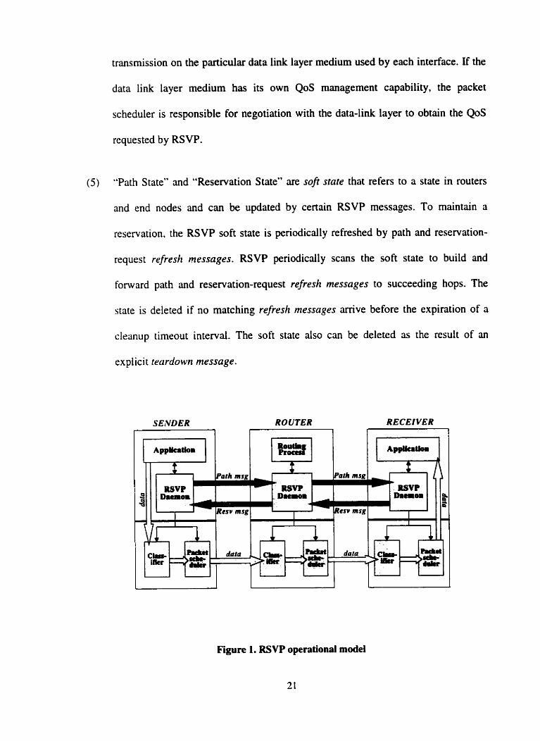
transmission on the paaicular data link layer medium used by each interface. If the
data link layer medium has its own QoS management capability, the packet
scheduler is responsible for negotiation with the data-link layer to obtain the QoS
requested by RSVP.
( 5 ) "Path State" and "Reservation State" are sofi state that refen to a state in routen
and end nodes and c m be updated by certain RSVP messages. To maintain a
reservation. the RSVP soft state is periodically refreshed by path and reservation-
request refresh messages. RSVP periodically scans the soft state to build and
forward path and reservation-request refresh messages to succeeding hops. The
state is deleted if no matching refresh messages arrive before the expiration of a
clranup timeout interval. The soft stcite also can be deleted as the result of an
explicit rrcirdown message.
SENDER ROUTER 7
+ 1 RSVP
- Datroii
esv msg esv msg
RECEIVER
Figure 1. RSVP operational mode1
2.5 Reliable Multimedia Communication
This is another important issue of multimedia data transmission. After the data
transmission starts, there should be some adaptation mechanism to make sure that it gets
the desired resource. The packet-loss rate typically represents a communication service's
dependability and reliability. In QoS guaranteed communication. the packet loss is
reduced to zero theoreticdly. Because, first, the packet loss rate cm serve as a QoS
parameter which is considered to be guaranteed during the QoS routing or admission
control. If it could not be guuanteed, the transmission request would be rejected.
Moreover. most of today's network technologies are designed to be used on fiber optic
networks. which are highly reliable since the use of opticd fibers reduces the
transmission error rate to a negligible level. In such case, most packet losses occur
because the buffer overflows which results From traffic congestion at network switches or
routers. But in QoS guaranteed communication. the required bandwidth is reserved
before hands. and is always there when it is needed, so the congestion induced packet
Iosses should never occur or at least be rninimized.
Therefore. in multimedia data transmission. the reliability is more significant in
terrns of a longer time scale. That is, it should be considered in session management level
as opposed to packet level [LOI. To provide the promised guaranteed service in long time
scale. the major problem that should be concemed is the network component failures. like
link or router failures. The network has to quickly perform QoS adaptation to restore the
QoS connections affected by such component failures. Since the QoS guarantee is
realizrd by reserving resources on a static vinually established path, and the packets are
transferred only via that path. QoS adaptation is to establish a new path. There are several
strategies of QoS adaptation.
One strategy is to setup a backup path for each QoS connection a priori to
guarantee quick and successful recovery [IO]. The same arnount of resources is reserved
on the backup path as its primary path in order to provide the same QoS upon activation.
When the system detects there is a failure on the current path, the backup path is
established and the traffic is switched to the backup path. The resources of the backup
paths can be used by other transmission service types, e.g.. best-effort traffic. but they
cannot be used to accomrnodated other QoS connections. And traffics of other service
types that are flowing on the backup channel should be preemptive when the backup
chmnel is activated. The advantap of having a backup channel at hand is that the tirne of
QoS connection recovery is reduced to the minimum. So the network c m respond and re-
route the flow every quickly in case of the primary path mal-functioning. This
charûcteristic is very crucial for real-time applications. But the disadvantage is chat the
backup path is routed disjointedly with its primary. it reduces the network capacity of
accommodating QoS connections by at least 50 percent.
Another strategy is not to equip each QoS connection with a backup channel, and
it is used with the pre-computed paths. Upon detecting the failure, the system will run its
path selection process to select another path, frorn its preîomputed path base. which
does not contain the failed router or link. This approach does not reduce the network
capacity. but it is only good for the systems that are based on pre-computed paths.
othenvise the QoS re-routing time may be long enough to min the data transmission,
which is not acceptable by real-time applications.
2.6 Related Works on QoS Architecture
There have been many efforts both in academic research and industry
cornmunities on QoS architectures to provide QoS guarantees for multimedia
applications. We'll present a few of them that gave us helpful ideas to our design.
To support the distributed multimedia applications, dl the components of the
distnbuted systern rnust participate in the activities of providing the desired QoS
guarantees. The participating components should include network. the end-systems. and
the application. There are a number of proposeci QoS architectures. We classify them
roughly into two categories.
( i ) Some QoS architectures provide QoS guwantees to the multimedia data
transmission from the viewpoint of network resource management. The QoS
architectures of this class concentrate on the network resource management approach
with respect to QoS routing, efficient use of the network resource. and making using of
resource reservation protocols to provide QoS guarantees dong the dedicated end-to-end
path between the sending and receiving end systems. Following are two examples OF this
class of QoS architecture.
S M M Proiect of un Integrated Netwo rk A rchitectrr re for Integrnted Services
The Server and Agent based Active Management (SAAM) project at Naval
Postgraduate School extends the idea of route server. The proposed architecture consists
of lightweight routers and a small set of heavyweight servers [ I l . There is a server for
one network domain to that perform QoS routing and most network management and
control tasks on behalf of the routen in the domain. The serven maintain a path
information base, with which QoS routing and re-routing are implemented. In the
proposed architecture, the router does not participate in QoS routing, it just updütes its
tlow-based routing table with route data passed down from the server. The server
performs the QoS routing based on the path performance parameters stored in the path
information base. The path parameters considered in routing include: the target upper
bound on the total packet delay; amount of pre-allocated link bandwidth. These
parameters are aggregated from link level performance data passed up fom each router
in the domain. The Router Server c m easily allocate a suitable path for a QoS request.
and ais0 quickly update the path information when there is a change in the performance
of a service pipe. For details of the SAAM project, refer to 11).
Advnrt ce Reservation Architectrrre
A project on Advance QoS Reservations on intemet was developed at USC
Information Sciences Institute. The project proposed architecture for Advance
Reservation Servers (ARS), by which no QoS reservation state. scheduling state or
routing state need to be set up in the actuai routers until the time the reservation is
rstablished [8]. The architecture is designed in cater of a variety of circumstances in
which users will want to make an advmce reservation, reserving a QoS now that will
takes effect in the future. In such case, the sender or the receiver may register the advance
reservation with the ARS. The ARS keeps the advance reservations active and ensures
that actual reservations can be established at the advance reservation start-time. The
architecture is also based on the domain model, that is, there is an ARS in each domain,
and each ARS communicates with the ARS in each adjacent domain. To select the paih
for a request, the ARS participate in both the intra-domain routing protocols and inter-
dornain routing protocols. The research focuses on the advance reservation signaling for
both multicast and unicast circumstances. that is. how the ARS CO-operate to find the path
and make reservation for a session.
(ii) Instead of concentrate on the network management, some researches
concentrate on design of QoS management architecture for the multimedia application
side. This way, the multimedia applications have the capability to perfonn the QoS
management by building themselves on top of such QoS architectures. The following is
an example of this category.
A .qenerd frumework for OoS mclnagemrnt for distribirted MULTIMEDIA
a p pl iccr fions
This research proposes a general QoS management frarnework which supports the
dynamic configuration of systern components to support the QoS requirements for the
user of a specific application [16]. The architecture concentrates on QoS negotiation and
adaptation. [t provides a QoS graphical interface for distributed multimedia application to
nllow the user to specify hisher requirements in terms of high-level QoS parameters in a
user profile. The user profile contains desired QoS, the cost, the worst acceptable values
and the importance factor of each desired value. There is a QoS manager for the
distributed multimedia application that is in charge of the QoS negotiation and
adaptation. The negotiation is based on the user profile and the multimedia document to
be played. The QoS manager performs the negotiation to choose the best system
configuration that can support the user requirements. The system configuration includes
transmission parameters of the multimedia server, network. and the client machine. Then
the QoS manager risks the network and multimedia server to reserve the corresponding
resources. In case of QoS violation during the transmission. the QoS manager will choose
another system configuration to make the adaptation.
We think the most significant characteristic of this architecture is its definition of
s ystrm configuration. It is divided into functional configuration and physical
configuration. Functional configuration consists of functional and resource requirements
of each system component, which should be mapped to corresponding physical
configuration. Such mnpping includes the translation of functional requirements to
physical parmeters. and choice of appropriate networks to support the data transmission
specified by the functional configuration. Unfonunately. the research didn't give us a
clrar mechanism of how to get the functional configuration based on a user profile. and
how to rnap it to the physical configuration. especially for network part. but left the work
to the design of distributed multimedia applications and other QoS network management
architectures.
CHAPTER 3
IMPLEMENTATION TECHNOLOGIES
To deploy our QoS architecture, we use the combination of the mobile agent and
active network as the implementation technology. in this chapter. we will investigate the
usage. functionality and advantages of mobile agent and active network technology. and
the relationship between them. Based on these knowledge. we will conclude the reasons
and motivations for using these two technologies for our architecture in the next chapter.
3.1 Mobile Agent Technologies
Software agent technology is actively and successfully being introduced in
network management and intelligent network services such as Web service, e-commerce,
information retrievd, etc. And there is definitely an increasing interest in the reseiirch and
development in the use of agents.
The dramatic increases in developmeni of network services demand more
tlexible, reliable and efficient technologies for designing, implementing and maintenance
of these services. Moreover. the network system itself is becoming larger and more
complex with e huge arnount of very heterogeneous components and subsystems. To
manage the network also needs more efficient technologies. These are the main
motivations of software agent research.
3.1.1 What is an agent?
There are already plenty of agent definitions in the researches. In this thesis, we
won't make such effort again to define the agent. Instead, we shall describe its base ideas.
from which we c m easily conclude what a software agent is? Software agent technology
derived from Distributed Artificial Intelligence and Distribrtted Problenz Solving suategy.
hstead of one centralized and very large application that encodes the complete
intelligence of the system, a number of relatively smdl systems. or agents, are involved
in a cooperative effort to solve the problerns. Each of these srnall systems is capable of
addressing a certain aspect of a problem. They are tied together through a communication
system. by which they exchange information and corne up with stntegies to make
progress or to combine the individual's result into a solution. Each of the cooperating
systems may be considered an agent [32]. This is the initial base idea of software agent.
Another base idea of agent technology is that. instead of issuing explicit instructions, the
user only needs to specify a high-level goal and required information for achieving the
goal. while the approach of how and where to achieve the goal is lrft to the agent.
The purpose or usage of software agents will become more sprcific if we attribute
the agents by some propenies or attributes, like rracrive. crutonomolts. comrniuzicative.
frorni~iy. CO-aperc~five. mobile. etc. [25, 26. 30, 3 1. 321. Agents of different purpose may
have ciIl or some of these attributes.
Among the meaningful subctasses of agent. the "mobile cigent*' is used most often
in agent research and industrial areas. It is even referred as the general name of agents. Its
complernentary set, "stationary agent" c m be then seen as special instance of mobile
agent whose mobile capability is just not used. Here, we can generally define mobile
agent as, mobile agent is a subset of software agent, which c m suspend its execution at
one machine and move to another machine to continue its work.
3.1.2 The general advantages of using agent
The alternatives to mobile agent include messaging. simple daiagrms. sockets.
remote procedure cal1 (RPC) and conversations [3 11. These are the dominant methods in
network computing areas. The various attributes of agents, like mobility. communication.
CO-operation, and flrxibility, c m bring some advantages over these traditional distributed
computing iipproaches, which are also the motivations for us to use mobile agent to
achieve QoS management. The advantâges c m be summarized as follows [25.3 1.321:
dsynchronous autonomous interaction - Agent platforms employ messaging
frmeworks for transport and information exchange. which rneans the interaction
between agents are asynchronous. Furthemore, mobile agent can be delegated to
perform certain tasks autonomously even if the delegating entity is not active
[33 1.
Agents facifitate l e inte~action with real-tirne systems - Real- time applications
have high restrictions on network delay. ff the latency in network transmission is
high compared to real-time constrains imposed by the extemal equipment.
sending a mobile agent to execute close to a real-time system may reduce the
possible delays caused by network congestion to the minimum. Agent program
executing locally, even if inierpreted. has a relatively low and bounded latency
and can provide more opportunities for enor recovery [3 11.
Agents can be the robustness of reliabiliîy of network services - Mobile agent
migrations use the message passing framework. which provides reliable transport
but without requinng reliable communication. On the contrary, W C
implementation relies on the integrity network communication. Even though the
unreliable communication layers c m support RPC, the synchronous nature of this
method means that re-transmission delays eventually become unacceptable. in
addition. the mobile agents add fault tolerance feature. If a distributed system
malfunctions, mobile agents can be used to increase avaiiability of certain
services of the system, since the mobile agent c m carry with it or know how to
ûccess knowledge about altemate sources [3 1. 321.
Agents bring convenience in providing and searching of network services -
Mobile agents c m be used to extend capabilities of network service providing
applications. For example, agent c m express the application-level protocol in a
device independent way which may be required to perform a transaction. On the
other hand. agent also can offer dvantages to customer in searching for services.
For example, the mobile agent may be able to present the customer's desire as a
query to a number of potential vendors to search the best match [?7,32].
Easy, quick and inexpensive to design, rnaintain and update - Creating
distnbuted systems based on mobile agents is relatively easy, and so is the
maintenance and updating. The agent is self-contained and flexible. It is thus can
be de-coupled with other components. and capable of hinctioning with relatively
little coordination with existing software [3 11.
Flexibility - This is needed when handling heterogeneous environment.
increasing size of network, new service launch. and the scalability. Developing
network software or management application using mobile agent c m be done in a
one-side-programrning, and application-oriented way. in this way. the developer
only needs to focus on the functionality of the application. Agents will adapt
themselves in an evolutionary. heterogneous environment. This leads to extreme
tlexibility and efficiency [25].
While none of the advantages given above is overwhelmingiy strong individually.
but we believe that the aggregate advantage of mobile agents is ovenvhelrningly strong.
And in certain cases, as explained above, the use of mobile agents have advantages over
other implementations. The traditional solutions might be less efficient. difficult to
deploy or awkward. Especidly. mobile agent c m find many interesting applications and
h a a jreat potential in intelligent information retrievai. network management. and
network services. Of dl these areas. the most promising sub-topic is the launch of new
services and service upgrade. Based on these thoughts, we deploy Our QoS management
architecture as an application using mobile agent technology.
Our architecture is designed to provide network QoS management. The route
server is the leading actor in our architecture. It is the entity that is in charge of the QoS
management in certain domain. In order to make this centralized kind of approach to
produce an open management architecture with scaiability, efficiency, and flexibility,
which are the requirements of the heterogeneous network. we use CO-operative agents to
carry out the tasks of the route server, instead of centerîng dl the management
computation in route server itself. This allows the intelligence and management
functionaiity to be moved from the operation center. the route server, to the related
nrtwork devices where the operation required data is located. in the later chapter, we will
discuss more about the idea of using mobile agent in Our QoS management architecture.
3.1.3 Mobile agent management systems
An agent management platform or system is an essential base for any specialized
agent applications. There are severai research or commercial products. like Aglet,
Concordia. Crosshopper and FPA-OS [25]. The general requirements of a mobile agent
management system include two parts. First. it is composed of mobile agents. Each agent
is built with a personal part that contains data and code for achieving its persona1 goal.
and a gencral part that contains general capabilities such as communication. management,
and migration. etc. Second, the node that hosts the agents should have an agent
compatible environment to provide the agent with necessary services such as
communication facility. security facility, migration facility. and resource access facility.
The cotrzm»licution fuciliy is to support data transmitting and receiving. The secicrity
jiicilic provides secunty service for both agent and host itself. It defines the mechanisms
and procedures of authentication. access control, and etc. The migrution fncility is for
sending and receiving mobile agents. The resoirrce uccrssfaciiity gants access models to
agents for accessing the local resources. For examples of mobile agent management
system, please refer to [25] .
Active Network Technology
The active network approach is motivated by both new applications that require
network services to perform user-driven computation at network intermediate nodes. and
the emergence of the mobile code technologies that make dynamic network service
innovation attriinable. In this sub-section. we give a snapshot of what the active network
is. and the two approaches for the realization of active network.
3.2.1 What is active network?
Active networks represent a novel approach to network architecture. Relative1 y.
the traditionai network is refened as passive network in the sense that the routers within
the network only passively pass the actual user data packets opaquely without
examination or modification. Although they may modify a packet's header. the
computation and associated router actions are only up to the network layer. and
independent of the user application that generates the packets [34]. An active network is a
network that allows intermediate routers to perform computations up to the application
layer. Active networks are "active" in two respects:
(i) The network intermediate nodes. Le., routers or switches. are active. They are
able to perform customized computations on the messages flowing though
them for the application purpose.
(ii) The application packets are active. The network applications cm "program"
the network by supplying their own programs which travel inside network
packets and perfom the computations in certain execution environment at
routers or switches. thereby, the user applications tailor the state and behavior
of these network node to be application-specific.
With the fast growth of network applications. there are more and more
requirements that need to be satisfied by the network services that involve processing at
intemediate nodes. Today's passive networks have severai obstacles to support such
requirements: the difficulty of integrating new technologies and standards into the shared
network infrastructure; poor performance due to redundant operations at several protocol
layers; and difficulty accommodating new network protocol and services in the existing
architectural mode1 [37). Active network approach emerged to address these issues. It is
an effective way to rapidly adapt the network to the ever-changing application's
requirements, and enable new network applications. More specifically, the principal
advantages of active network are:
It provides a means to introduce adaptive protocols. Instead of just sending
messages with fixed data format bounded by the existing protocols. the user
application cm customize the message processing by sending its own program to
the routers. The prograrn behaves like an ad hoc protocol to suit its own purposes,
or even as genenc protocols for a group of applications [37,40].
It is a way of implementing fine grained application-specific functions at strategic
points within the network. Applications can achieve this by injecting programs
that perform such functions into the network nodes [40].
It provides a powerful platform for application-driven customization of the
network infrastructure. allowing new services to be deployed at a faster pace.
which, in traditional network, can be sustained by vendor driven consensus and
standardization processes [40].
It creates a new degree of freedom in network architecture, which in tum opens
up the opponuniiy to speed up network evolution and thus accommodates new
network types. aigonthms. and application.
It leads to better end-to-end performance of applications. Although the active
processing overheads at intermediate nodes degrade the network performance to
at least some extend, the performance of applications can more than make up for
3.2.2 Two approaches to active networks
There are two approaches to realize the active network. discrete and integrated.
depending on whether the data and the prograrn to process the data are carried discretely,
i.e.. within sepsate packets. or integrally.
Discrete approach
It is also called programmable switches, or active nodes approach. In this
approach, the message processing is sepanied from the procedure of injecting the
predefined functions aiming to process the messages into the active node. The
applications inject their custom processing prograrns into active nodes before sending the
data. The data messages maintain the existing packet format. They carry some identifiers
or references in the headers to indicate which predefined function in the crossing active
node should be dispatched to operate on their contents. and they provide the panmeters
for the operation. The discrete rnechanism for loading the program and operating the
messages might be valuable for the cases in which program loading must be carefully
controlled by network administrator, nther than individual network applications or end
users. Like in the Internet. program loading would be restricted to a router's operator who
is authenticated to do so. It dlows operaton to dynamically load code into the required
routers for router extensibility purpose [34. 371.
Intearated approach
It is also cdled ccrpsriles, or crctive pockets approach. In this approach. message.
or called capsule, which passes between nodes, carries a program fragment in addition to
the data contents. There are no predefined active code resides in the crossing nodes. but
the nodes are also active in the sense that they are required to have a transient execution
environment. This environment is to support the program of the message CO execute
safely. and to dlow the program to perform the computation up to the application layer.
When a capsule arrives at an active node. the program in the message is dispatched to he
transient execution environment either to perform computations on the date contents of
the sarne message, or to execute in order to change the state or the behavior of the node.
The program of the message cm also invoke "build-in" primitives of the node, which
may provide access to resources extemal to the transient execution environment. This
approach gives more freedom and flexibility to the application. but as a cost, it brings up
more safety and security concems to the crossing network nodes [34, 371.
Our architecture c m be seen as an application on the network. When it deals with
the resource reservation with the routers, it needs to send not only the QoS reservation
parameters to the related routers, but also the code to perforrn the operation of setting the
reservation states in the router. The router's behavior. in this context, is driven by the
purpose of our application. We'll discuss in later chapter about how we make use of the
idea and the approaches of active network to handle the resource reservation task.
We implement our architecture on a mobile agent platform. and use mobile agent
to realize the active network approaches for resource reservation. Developing an
architecture that integrates mobile agent and active network technologies is guided by the
fact that these two technologies are not totally extraneous to each other [9]. We now
explore the relations between thern.
3.3 Mobile Agent vs. Active Network
The simi!arity between the two ideas is obvious. First, they both use
programmatic entities that carry data and codes which is to execute on the data. Second.
mobile agents and the active packets are both sent by the users and perform tasks for the
users' purposes. Third, they can move from one location to another. Further, many active
network architectures use mobile code techniques that are very close to mobile agent
technology. However, the idea of active networks is much more general. Active networks
visualize the network as a collection of active nodes that c m perform any computations.
and a collection of active packets that cany piece of code (programs). From this point of
view. a mobile agent may be regarded as a specific type of an active packet. and a
network node that are with agent execution environment could be regarded as a specific
type of an active node.
A fundamentai difference between the two ideas is that active networks use the
concept of network layer processing whereas mobile agent systems run as application
programs on application layer [37]. Or. we cm say that active network and mobile agent
are the same idea at different network layers. The active network c m be considered as
"the specidization of mobile agents systems" to perform the functions nt the network
liiyer. Also. mobile agent c m be regarded as a specific type of an active packet that
performs application layer functions. Guided by the relationship betweeo the two ideas.
we use the CO-operative agents. ranging from QoS provisioning agents working at
application level to resource management agents that program the routers at network
level. to accomplish the functionality of our QoS management architecture.
CHAPTER 4
OVERVIEW OF THE ARCHITECTURE AND
IMPLEMENTATION PLATFORM
4.1 Overview of the Architecture
Airning to solve the problems of QoS management in today's network as we
listed in the first îhapter, we propose to use a route server to take over the QoS
management tasks from the individual routers. Briefly, in the route server architecture,
the establishment and maintenance of a QoS session go through the following related, but
de-coupled phases:
( 1 ) First. the sender and receiver negotiate with each other to reach an
agreement on the speci fication of QoS request.
(7 ) Then the route server performs QoS routing to select an end-ro-end path
from the sender to the receiver that cm satisfy the request.
(3) Before transmission starts. the route server makes resource reservation dong
the selected path for the sender and receiver.
(4) During the actud data transmission. route server monitors the transmission
performance, in case of QoS requirement violation. the route server will
perform adaptation actions to make sure that the session gets the promised
QoS.
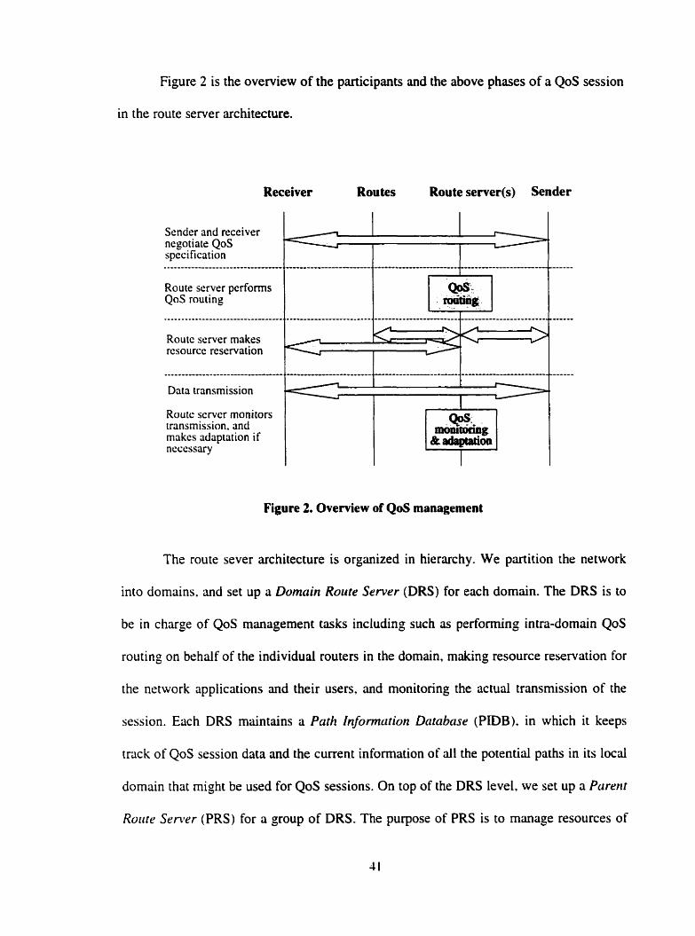
Figure 2 is the overview of the participants and the above phases of a QoS session
in the route server architecture.
Receiver Routes Route server(s) Sender
Route scrver pcrforms QoS routing
Sender and receiver ncgotiale QoS specification
Route semer makes rcsourcc rcservation
-I L
Figure 2. Overview of QoS management
- - - - - - - - - . . - - - - - - - - - -
Data transmission
Route scmcr moni tors
The route sever architecture is organized in hierarchy. We partition the network
transmission. and rnakcs adaptation if ncccssary
into domains, and set up a Domain Route Servrr (DRS) for each domain. The DRS is to
m0111twng W. &iuiapwnn
I J
be in charge of QoS management tasks including such as performing intra-dornain QoS
routing on behalf of the individual routers in the domain. making resource reservation for
the network applications and their users, and monitoring the actud transmission of the
session. Each DRS maintains a Parh hformcirion Database (PIDB). in which it keeps
track of QoS session data and the current information of ail the potential paths in its local
domain that rnight be used for QoS sessions. On top of the DRS level. we set up a Parent
Rorrtr Senvr (PRS) for a group of DRS. The purpose of PRS is to manage resources of
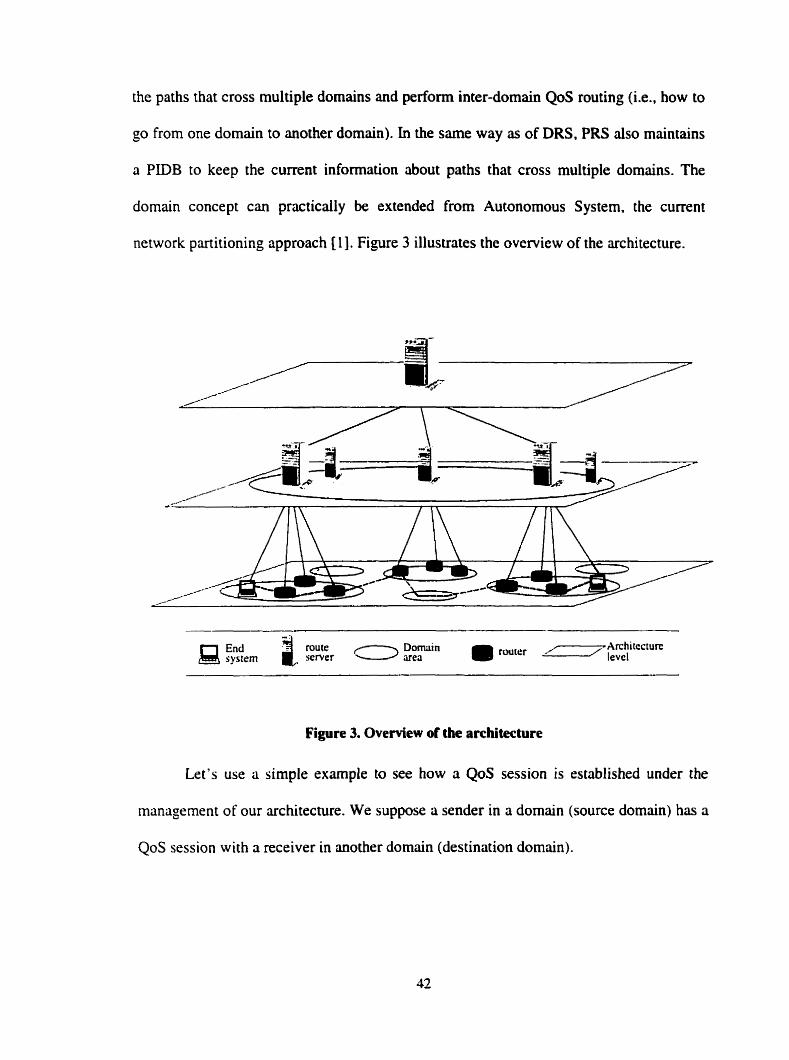
the paths that cross multiple domains and perform inter-domain QoS routing (i.e., how to
go from one domain to another domain). In the same way as of DRS, PRS also maintains
a PIDB to keep the current information about paths that cross multiple domains. The
domain concept c m practically be extended from Autonomous System. the current
network partitioning approach [l]. Figure 3 illustrates the overview of the architecture.
Figure 3. Ovemew of the architecture
Let's use a simple example to see how a QoS session is established under the
management of Our architecture. We suppose a sender in a domain (source domain) has a
QoS session with a receiver in another domain (destination domain).
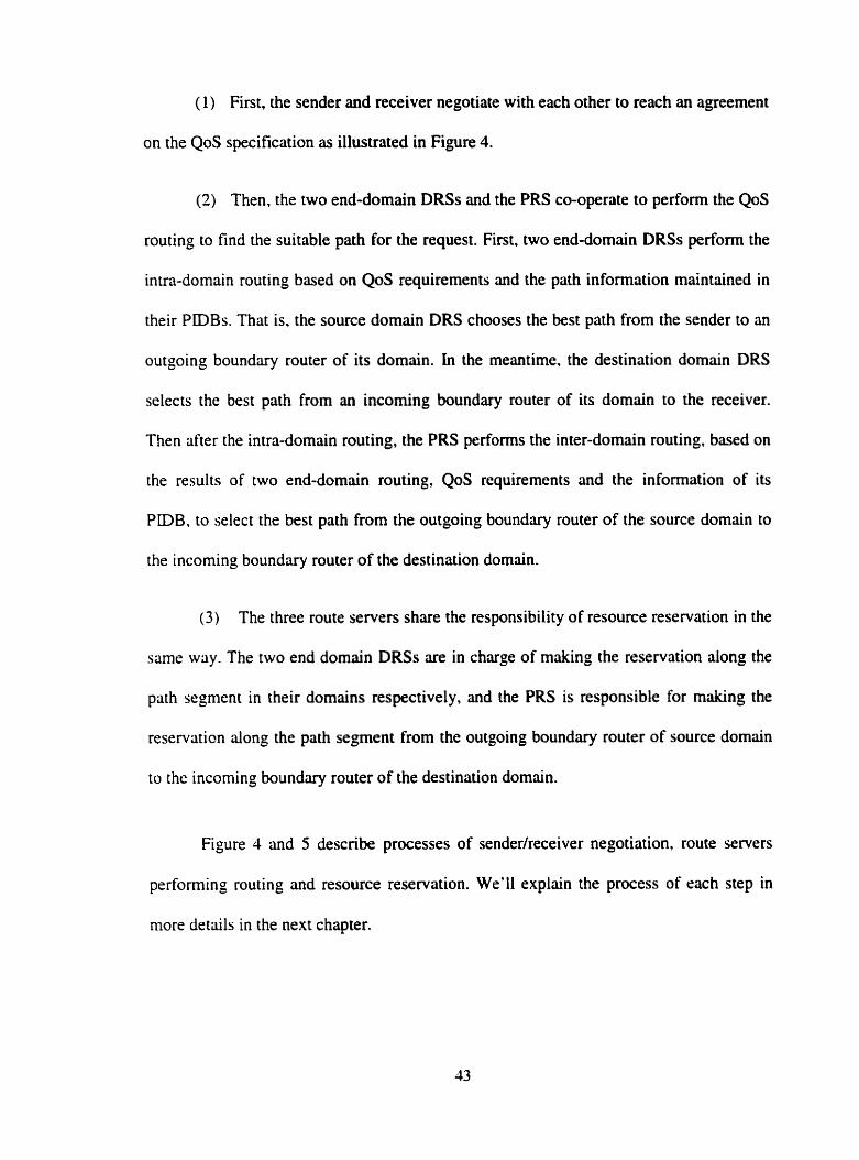
( 1) First, the sender and receiver negotiate with each other to reach an agreement
on the QoS specification as illustrated in Figure 4.
(2) Then, the two end-domain DRSs and the PRS CO-operate to perform the QoS
routing to find the suitable path for the request. Fint, two end-domain DRSs perform the
intrn-domain routing based on QoS requirements and the path information maintained in
their PiDBs. That is. the source domain DRS chooses the best path from the sender to an
outgoing boundary router of its domain. in the meantirne, the destination domain DRS
selects the best path from an incorning boundary router of its domain to the receiver.
Then after the intra-domain routing, the PRS performs the inter-domain routing, based on
the results of two end-domain routing, QoS requirements and the information of its
PIDB. to select the best path from the outgoing boundary router of the source domain to
the incorning boundary router of the destination domain.
(3) The three route servers share the responsibility of resource reservation in the
same way. The two end domain DRSs are in charge of making the reservation dong the
path segment in their domains respectively, and the PRS is responsible for making the
reservation dong the path segment from the outgoing boundary router of source domain
to the incoming boundary router of the destination domain.
Figure 4 and 5 describe processes of sendedreceiver negotiation, route servers
performing routing and resource reservation. We'll explain the process of rach step in
more details in the next chapter.
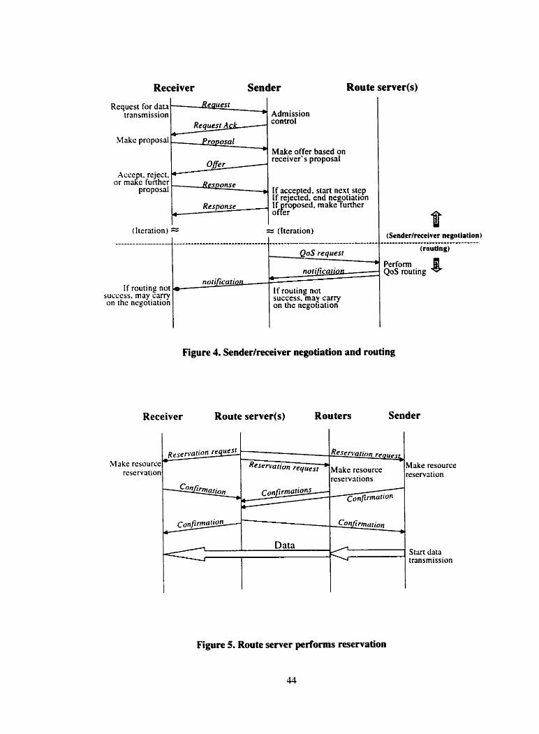
Receiver Sender Route server(s)
Requcst for data transmission
Makc proposai
Response w
Admission control
Make offer based on receiver's proposal
If accepted. start ncxc stcp If rejected, end ne otiation If roposed. rnake%rthcr O f L
(Itcration) == = (Iteration)
If routing not succcss. may carry on the ncgotiation
norificatipLt no f ificario~i
1
If routine not success,-may carry on the negotiation
/ (Senderlreceiver negoiiation)
Perform QoS routing 8
Figure 4. Senderlreceiver negotiation and routing
Receiver Route server(s) Rou ters Sender
Figure 5. Route server performs resewation
Resrnlurion rpqUpIL
Makc rerourcc reservntions
~ ~ n f i r m ~ r i o n
- Reservarion re4ilest *
c o n f i r m ~ r i o n s - *+ +
Make rcsourcc reservation
Make rcsource msenati.n
Cunfirmmion rn
R r r r r r a t i ~ n rt'414es'
Co'/irm~[ron
S tut data transmission
I
The responsibilities of the DRS are sumrnwized as follows:
Handle the QoS negotiation requesü generated from the end systems in its
domain. Perform negotiation for the session parties to determine the QoS
speci fications.
Perform policy control to determine whether a user has administrative
permission to make the QoS reservation it the domain;
Perform the intra-domain QoS routing on behalf of a group of routers in its
domain based on the local path information it keeps in its path information
database;
Report to the PRS about the QoS specifications and domain intra-routing
results.
After the successful routing, register the corresponding QoS specification with
the selected path as the reservation request, which could be the advance
reservation request, in the P D B ;
Communicate with the end-systems and the related routers dong the path
segment in the domain of the selected path to make the actual resource
reservation.
Main tain the reserved resources b y sending re fresh messages to the related
nodes in its domain at specified time intervais.
Monitor the data transmission. When the QoS violation is detected, it will
configure a new route which might support the initiaily agreed QoS, and
perform the route transition without userhpplication intervention.
Collect the link performance data from the routers in the domain. The data
should include, link availability. available bandwidth. time duration for this
available bandwidth, minimal packet delay, and MTU. etc.
Maintain and update its regional PIDB to store the QoS requests of registered
QoS sessions and the up-to-data information of ail the potential local paths
that might be used for QoS requests. It cornputes the path information and
updates QoS session registration with the data of resource usage while making
reservation and when the reservation is expired. And dso. it updates the PiDB
with the data it g t s from the routers.
Be able to invoke different QoS routing algorithrns under different network
conditions.
The responsibilities of the PRS are similar to that of the DRS. but with the
following differences:
There is no need for PRS to handle the QoS negotiation request. since the
requests are sent to the DRS in every domain.
PRS performs the inter-domain QoS routing using the intra-domain routing
results of two end domains to find out how to go from the outgoing boundary
router of the source domain to the incoming boundary router of the destination
domain.
The information that the PRS keeps in its PlDB is about the paths that cross
multiple domains.
PRS collects link data from the boundary routers of every domain since they
are the nodes that compose the paths crossing multiple domains.
The purpose of organizing the route servers in the hierarchy is that, each DRS can
only monitor and maintain the paths within the radius of its own network domain. It
cannot independently monitor and control the network conditions over a long-distance
path. More particularly. the DRS only has the knowledge of the paths of its domain.
When there are more than one domain that is available to go across towards the
destination domain. it is hard for the DRS to decide through which domain the flow
should go. Therefore. we use the PRS to monitor the prths that cross multiple domains
and perform inter-domain routing. We c m say that the route servers fom a logicd
overlay-controlling network over the physical network.
4.2 Further Advantages of Route Server Architecture
The route server architecture not only c m solve the problerns of individual routers
performing QoS management as we discussed Our motivations in the first chapter. but
also. there are some other intuition and rdvantages of our design.
First. let's consider road trafic monitoring during rash hours in a large city like
Toronto. In this case, if we use helicopters to monitor the traffic on the roads for their
respective coverage region. the uaffic in the region can be effectively monitored and
controlled from an overall viewpoint, and the congestion cm be detected earlier. in
contrat, individual rnotorist cm only monitor tnffic within a very short radius and
cannot independently foresee congestion possibilities. The current network handles the
QoS management using individual router is like road traffic monitoring that depends
mostly on motorist. Our QoS management architecture follows the helicopter mode]. The
role of the route server in a domain is like the role of the helicopter in its coverage region.
The route server will periodically collect network state information and maintain "ready
to use" path data in the Path information Database.
Second benefit of the architecture is that by holding the bandwidth management
right in a centrdized hand, it is easy to use bandwidth resources more efficiently. For
sxample, the network manager may facilitates bandwidth utilization based on dynamic
factors, such as time of day. application priority, and network conditions. or according to
defined policies. Al1 these policies and schedules can be managed and enforced from the
route server.
Third, speaking of policy, the route server architecture provides a way to
ctntralize policy niles within a given domain. which ensures consistency and dso has
scalable performance. As a result. it simplifies the administrative challenge of
provisioning and managing network resources.
Fourth, the architecture can provide a cenualized reporting and accounting
mechanism for the network resource usage in the route server. which includes
monitoring, assessing, and reporting service quality to demonstrate the vdue of QoS to
the user applications, and initiating billing based on resource usage and the service that
wüs provided.
Al1 these characteristics are very beneficid and important for network
management in the sense of QoS.
4.3 Using Mobile Agent Technology to Implement the
Architecture
The purposr of Our architecture is twofold. first is to provide new network
services to distributed multimedia applications for handling the QoS, such that the burden
of QoS concems can be relieved from the design and implementation of multimedia
applications. Our architecture acts like a platform for multimedia applications and their
users to negotiate and determine the QoS requirements, then the route server will perform
the QoS routing, resource reservation. adaptation and real-time support for the QoS
session. Second purpose of the architecture is to perfonn network management over
network end-systems and routers in the sense of QoS. The route server oversees the
network resource usage and conditions in its controlling domain, collects up-to-date
network performance data. maintains the dynamic path information. and dispatches the
QoS sessions in the way to balance the network load and use the resources most
effectively. Therefore, in the context of these two general purposes, the route server is the
QoS management operation center to multimedia applications. network end-systems. and
routers. And the multimedia applications. the end-systems and the routers are the clients
of route server. To implement this client/server architecture, we investigate that the co-
operative-agent-based system c m be more beneficial in achieving the above objectives
over the traditional distributed computing paradigms.
The idea of using CO-operative agent system to carry out the tasks of the route
server is motivated by the fact that the architecture is a centralized approach seen from
the viewpoint of a domain. Thus, it may have weaknesses in scaiability. flexibility. and
maintainability to some extend. The cooperative-agent-based system is the natural
adoption to overcome these weaknesses due to the following reasons:
It c m solve the problems that are too large for a crntrdized single server to do
due to resource limitations, and it c m sheer the risk of having one centralized
system.
Agent-based systems cornmunicate through high-level messages in contrast to the
low-level messaging in distributed computing [26]. This allows the multiple
participants, like data senders, receivers. route servers and intermediate routers, to
connect and cooperate directly and naturally at application level.
It is a good solution to distributed problems. For example, in order for the route
server to provide QoS negotiation service to multimedia applications. it needs to
cornmunicate with the applications to get the necessary QoS parameters for data
transmission. It also needs to communicate with the data receivers to get the
desired quality and their real capabilities to receive the data. From the multimedia
applications' and receivers' point of view, in such case, using the traditionai
distributed computing paradigms, they have CO make a series of remote calls to the
route semer, which would bnng intemediate data across the network on each c d .
It is much more natural to get the agents to go to the negotiation parties and bnng
the computations to the data sources.
It enhances the modularity, which reduces complexity. The architecture is easy to
design. implement. maintain and update. An agent cm be designed to accomplish
a prirticular task. Al1 the agents cooperate with each other to achieve the ultimate
goal. When updating the architecture, only the relevant agents need to be
modified or replaced.
Agent cooperation has the advantage of providing "added value". That is. the
value gained from individual stand-done agents coordinating their actions by
working in cooperation, is greater than that gained from any individual agent. The
added value is the combination of speed, wont case performance, reliability.
adaptability, and accuracy [26].
4.4 The Co-operative Agents in the Architecture
The agents in our architecture include negotiation cigent. roiiting ~rgent.
Izo~isekeeping <[gent. reservation ngenl, refresiz agent, monitor agent and deteetion cigent.
They CO-operate with othen to accomplish the QoS management tasks of route server.
Each agent has the following knowledge: knowledge of how to perform its own task.
knowledge of how to gather the information required to perform the task. and knowledge
of other agents it must coordinate with in order to meet the task. The client of the
multimedia application (receiver) only needs to make a data transmission request io the
multimedia application (sender). and specifies the time that the transmission is wanted.
The multimedia application will then send a QoS management request to the route server
to invoke the QoS management mechanism of the architecture. The negotiation, routing,
and rcservation. etc., whch are performed by the CO-operative agents. will happen
transparently to the sender and receiver. We explain the characteristics and objectives of
each dedicated agent as one by one:
Negotiation Agent
- This is a mobile agent. It rnigrates from the route server to multimedia data
sender and receiver;
- It works in pair, one at the data sender side. and the other ai the receiver side:
- The one at the sender side collects QoS parameters from multimedia
application, while the one at the receiver side gets information from the
receiver the desired quaiity and user capabilities:
- It negotiates with its partner, on behalf of the sender or receiver. to reach a
final QoS specification that is agreed by the two parties.
The process of negotiation is substmtial repetitive behavior. Nesotiation
agents make less work for users and developee of multimedia application.
Further. the negotiation agent c m be developed with "learning" ability, then it cm
adapt, over tirne, to its user's preferences and habits to perform the negoüation
more intelligently and autonomously. This is beyond the area of this thesis, and
c m be a research topic in the future work.
Routing Agent
- This is a stationery agent. It works at the router server;
- It has the knowledge of the path information database (PIDB) that it is
ÿssociated with, and the knowledge of how to access the database:
- It gets the QoS specification from negotiation agents;
- It performs policy control according to the network policy and current
network situation to determine if the user has the permission to use or to
reserve the network resources;
- It performs intrdinter domain QoS routing based on the information of PIDB
to satisfy the QoS request;
- It registers the new request and updates the resource usage information in the
PIDB as the ternporary reservation of the request after the successful routing.
Housekeeping Agent
- This agent is a stationery agent, and works ai router server:
- We design to have a housekeeping agent that keeps running in every router
server. It behaves like a housekeeper of PIDB. It is attached to the PIDB, and
checks the time information and registration status of QoS requests every
short period;
- It triggers off the actual resource reservation whenever it detects it is about the
start time of a registered QoS session;
- It triggers off the refreshment of resource reservation for the active sessions at
specified time interval;
- It cleans up the expired QoS request regisuations at PiDB.
Reservation Agent
- This agent c m be mobile or stationary according to different implementing
iipproaches for making resource reservation. It may migrate to the related
network nodes to make the reservation, or just send messages to the nodes.
We will explain this in the next chapter.
- It constructs the required parameters for making reservation and makes the
actuai reservation with related routers and end systerns.
Refreshment Agent
- Same as the reservation agent. this agent may be mobile or stationary in
different impiementing approaches:
- Its purpose is to maintain the reserved resources for the active QoS sessions:
- It constmcts the required panmeters and refreshes the reservation with the
related routers and end systems at specified time intervals.
Monitor Agent
- It is a mobile agent. It migrates to the points where measurements cm be
performed. The location of these points needs further research.
- When the measured value of a QoS panmeter does not meet the agreed one in
the request, the monitor agent issues a notification to the route server.
indicating the violation. Then the necessary steps will follow to make the QoS
adaptation.
Detection Agent
- This agent is mobile. It migrates from the route server to the managed network
nodes of the router server;
- It collects the link performance data from the managed devices:
- It performs management cornputations to get the performance puameters.
Most of these parameter. such as delay, jitter rate. are not directly obtained
from the raw data collected from the nodes, but need to calculate their
average. variance, derivative. maximum, or minimum. etc.:
- It may r o m in a sub-domain or even the overall domain. and finally computes
the overall path information;
- It will return to the route server to update the P D B with the detected results.
Al1 these agents are created by the route server with required information. and
when nreded. sent out to the target network nodes where the agents rxecute their
programs. We implement our architecture on a mobile agent platform. SHIP-MAI. h
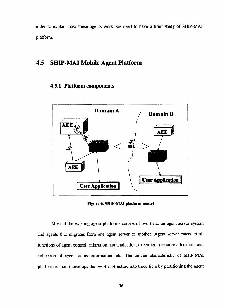
order to explain how these agents work, we need to have a brief study of SHIP-MAI
platforni.
4.5 SHIP-MAI Mobile Agent Platform
4.5.1 Platform components
Figure 6. SHIP-MAI platform madel
Most of the existing agent platfonns consist of two tiers: an agent server system
and agents that migrates from one agent server to another. Agent server caters to al1
functions of agent control. migration. authentication. execution, resource allocation. and
collection of agent status information, etc. The unique characteristic of SHIP-MAI
platfonn is that it develops the two-tier structure into threr tiers by partitioning the agent
server system into two complementary server components: Agent Execution
Environment ( M E ) and Agent Execution Controller (AEC). AEC performs the functions
of secunty, control, and management. whereas AEE is responsible for executing agent
code, dlocating resources, and enforcing secunty policies provided by the AEC. Further,
SHIP-MAI introduces a hierarchical architecture. It divides the network into domains,
one domain has at lest one AEC and the AEC controls d l the agents and AEEs in its
domain. Figure 6 shows SHIP-MAI platform model.
AEC
The role of an AEC can be sumrnarized in the following broad categories:
> First. it is the control center of agents and AEEs in the given domain. It
maintains control information conceming agents and AEEs. It creates.
monitors and destroys agents, registers and manages AEEs. It provides search
service of agents to other agents and AEEs in the domain. and to other AECs
outside the domain. It provides dispatch service to launch the agent to its
migration destination.
i Second. AEC acts as a repository for agents' work. In SHP-MAI, agents do
not cany their work from one node to another but transfer their working
results to the controlling AEC before rnigrating to anoiher host. This provides
a central persistence facility for the agent in case the AEE where the agent
works refuses to save the agent's work or is unable to do so.
i Third, AEC provides security services for agents and AEEs that the agents
visit. It provides service to agent with data encryption, and inter-domain
secure migration. AEC sets up secunty profile for every agent. Based on the
profile, agent cm authenticate itself and the host it visits, and AEE can
authorize the agent to do the required work with the local resources.
AEE
AEE rnainly is the working environment for agents to perform their tasks. It
accepts AEC as the authority and cimies out directives originated from AEC. Its
responsibilities include:
i Accept the agent and prepare to execute agent code by authenticating the
agent and its sending entity.
> Allocate resources and services to the incoming agents and execute agent
code. And keep uack of service usage of the agent.
i Keep track of the control information of the residing agents and comrnunicate
with the controlling AEC upon request.
i Provide means for agents to comrnunicate with each other and with the
controlling AEC.
Agent
Every agent on SHP-MAI consists of two parts: 3 specific part that is designed to
perform ü. specific task, and a general part that incorporates the following functions:
> Negotiate with the AEE about security, resource and services.
> Communication capability in order to communicate with other agents, and
also communicate with AEC to receive requests and to return results to the
AEC once the agent has fulfilled its mission.
> Mobile capability to move from one AEE to another as a result of its own
initiative or the controlling AEC's directive.
The benefils of AEC and AEE architecture
First, AEC provides a central fault tolerance systern. When an AEE is unable
to fulfill the agent's requirements. the AEC will act as a central repository of
agents' work and state.
Second. the ideas of domain and an AEC managing e group of AEEs simplify
the security problem. An AEC may be seen as a firewall from the security
point of view. It provides the functions to shield a group of machines in a
given domain and prevent the entry of malicious agents into the domain. Al1
AEEs in the domain are considered to be in a trusted environment. Elaborate
security measures are taken for agents migrating across different domains.
Once agents cross the firewall, only rudimentary security measures are taken
while agents migrate from one AEE to another AEE within the same domain.
Third. since AEC contains centralized information pertaining to d l agents.
the AEC c m participate in enhancing cooperation between agents.
AEC may provide agent lookup service. Any entity wishing to contact a
transportable agent m q do so by querying the agent's controlling AEC.
An AEC, in certain respects. represents a group of hosts. e.g., an AEC
provides access to a group of agent execution systerns. This may increase
interoperability between different agent systems since the AEC may provide
a list of agent systems supported, while the AEE need only support a given
agent system.
4.5.2 SHIP-MAI agent iife cycle
An agent's life goes through several stages as shown in Figure 7.
Agent creation
When a user wishes to nin a particuiar type of an agent, he/she asks the agent
application that is built on SHIP-MAI platform to submit a request on hislher behalf to
the controlling AEC. The M C examines the user's rights and the type of the agent
requested. It may or may not gant permission. If the permission is granted. an agent is
instantiated and the AEC provides the agent with a signed cenificate as the means to
authenticate itself. The certificate contains user D, agent ID, and list of resources to
which access may be granted, etc. Also, the agent is given the information to authenticate
the host -Es. With the information, the agent is able to verify the AEEs' signed
certificates. Then the agent is ready to rnigrate to the destination AEE.
Agent initiation
After creation, the agent is not yet active. It is to be deployed into an AEE and
initiated. Prior to entering the AEE, the agent needs to be authenticated and the list of
resources required by the agent is negotiated with the AEE.
Agent Execution
This is the active state of the agent. The agent code is executed to perform its
tasks. During the execution, agent may receive directives from the AEC as to migraie.
add tasks. or abort the operation. Agent may need to communicate with other agents for
the cooperation purpose.
Agent migration
Agent migration process of SHIP-MAI has two scenarios. Inter-domain
migration. and intra-domain migration. For inter-domain migrution, prior to the
migration. the agent's current controlling AEC has to negotiate with the AEC in the
foreign dornain to verify the agent's access rights and determine if the foreign AEC can
support the agent's resource requirements. Agent moves to the foreign domain through a
secure link (a SSL connection is established to accomplish the migration). and then it is
transferred to the desired AEE. After agent migration. a coordinator object of the agent is
created at the agent's domain of origin. This object is io handle the agent communication
with the origin domain AEC and other agents. The intrcz-domain migrrition is much
simpler. AEC only needs to verify the agent's migration request based on the agent's
security policy. Then the agent's current AEE is in charge of transferring the agent to
desired AEE in the same domain. The transfer needs not to be done on a secure link. in
both two scenarios, before the agent enters the desired AEE. it has to go through mutual
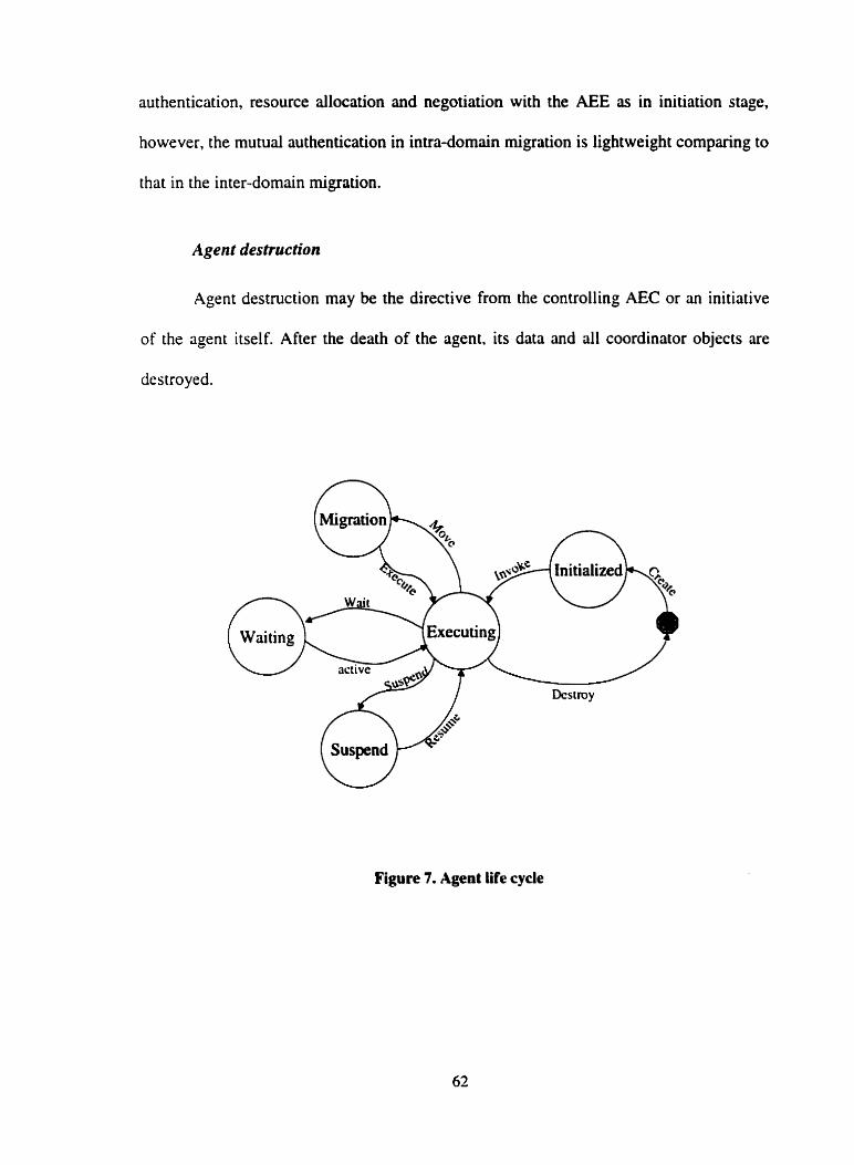
authentication, resource allocation and negotiation with the AEE as in initiation stage,
however, the mutual authentication in intra-domûin migration is lightweight cornparhg to
that in the inter-domain migration.
Agent desîruction
Agent destruction may be the directive from the controlling AEC or an initiative
of the agent itself. After the death of the agent. its data and al1 coordinator objects are
destroyed.
Figure 7. Agent life cycle
4.5.3 SHIP-MAI overall architecture
SHIP-MAI platform is implemented using JAVA as the prograrnming langage.
The overall system consists of the following packages, each deding with an aspect of the
functionality of the platform.
Communication: provides the communication support for the rest of the system.
The communication infrastructure of the platform is based on the messaging modei.
Agent application defined messages are wrapped as instances of the Message class of the
plritform. The Message class is responsible of sending the messages. The messages are
received and routed at the receiving ends via the instances of MessageHander class. The
objects subscribe certain messages with a messageHander. at the reception of such
messages. the mesSczgeHandler dynamically invokes the appropriate method on the
corresponding registered object.
Transport: is responsible for actud transport of Message instances via normal or
secure mode. A secure connection c m be obtained using the classes in this package.
Agent migration is also in the form of message and supported by this package.
Util: provides services for the various classes in other packages. The services -
include such as logging, error reporting, and data structure.
Rrsourcr: is responsible for the management of various resources available in the
system.
Security: manages the security policies including byte code verification. digitai
signature verification and generation, certificate management, and interfacing to extemal
serves. The classes and interfaces in this package are called upon during al1
communication sessions.
Svstem: is responsible for core system activities such as thread management,
event management. generic server implementation, server management. and interfacing
with remote client programs.
Protocol: defines the primitives to implement the various communication
protocols in the system. which include agent group protocol, AEC-peer exchange
protocol. AEE-peer exchange protocol. AEC-AEE exchange protocol, AEC-agent
exchünge protocol. and AEE-agent exchange protocol.
Service: serves as framework to manage extemai services that are available to the
agents and other components of the system.
Directorv: provides directory services to the rest of the system. The package also
contains supporting classes to interface and use extemai directory server such as
Netscape Directory Server whtch supports the LDAP protocol.
Persistence: provides persistence service to agent and the rest of the system.
Bridge to çxtemal persistence provider such as database server is implemented and
managed by this package.
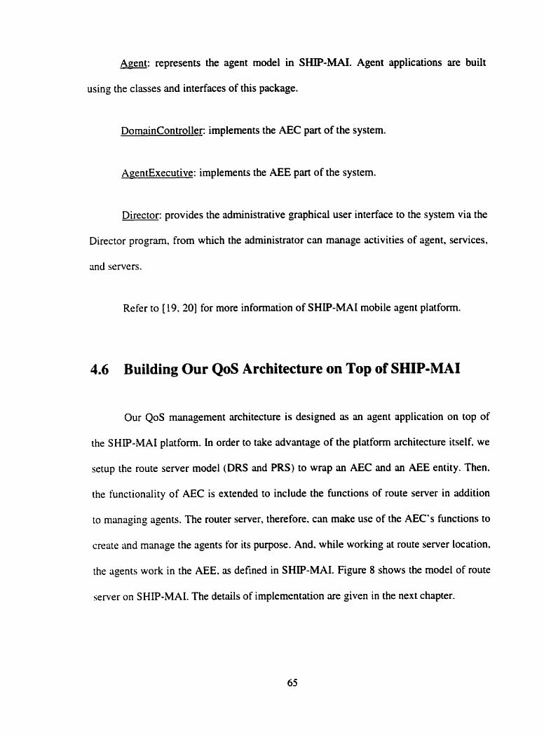
Agent: represents the agent mode1 in SHIP-MAI. Agent applications are built
using the classes and interfaces of this package.
DornainController: implements the AEC part of the system.
AoentExecutive: implements the AEE part of the system.
Director: provides the administrative graphical user interface to the system via the
Director program, from which the administrator c m manage activities of agent. services,
and servers.
Refer to (19.20j for more information of SHP-MAI mobile agent platform.
4.6 Building Our QoS Architecture on Top of SHIP-MAI
Our QoS management architecture is designed as an agent application on top of
the SHIP-MAI platform. In order to take advantage of the plaiform architecture itself. we
setup the route server model (DRS and PRS) to wrap an AEC and an AEE entity. Then,
the functionality of AEC is extended to include the functions of route server in addition
to managing agents. The router server, therefore, can make use of the AEC's functions to
create and manage the agents for its purpose. And. while working at route server location,
the agents work in the AEE. as defined in SHIP-MAI. Figure 8 shows the model of route
semer on SHIP-MAI. The details of implementation are given in the next chapter.
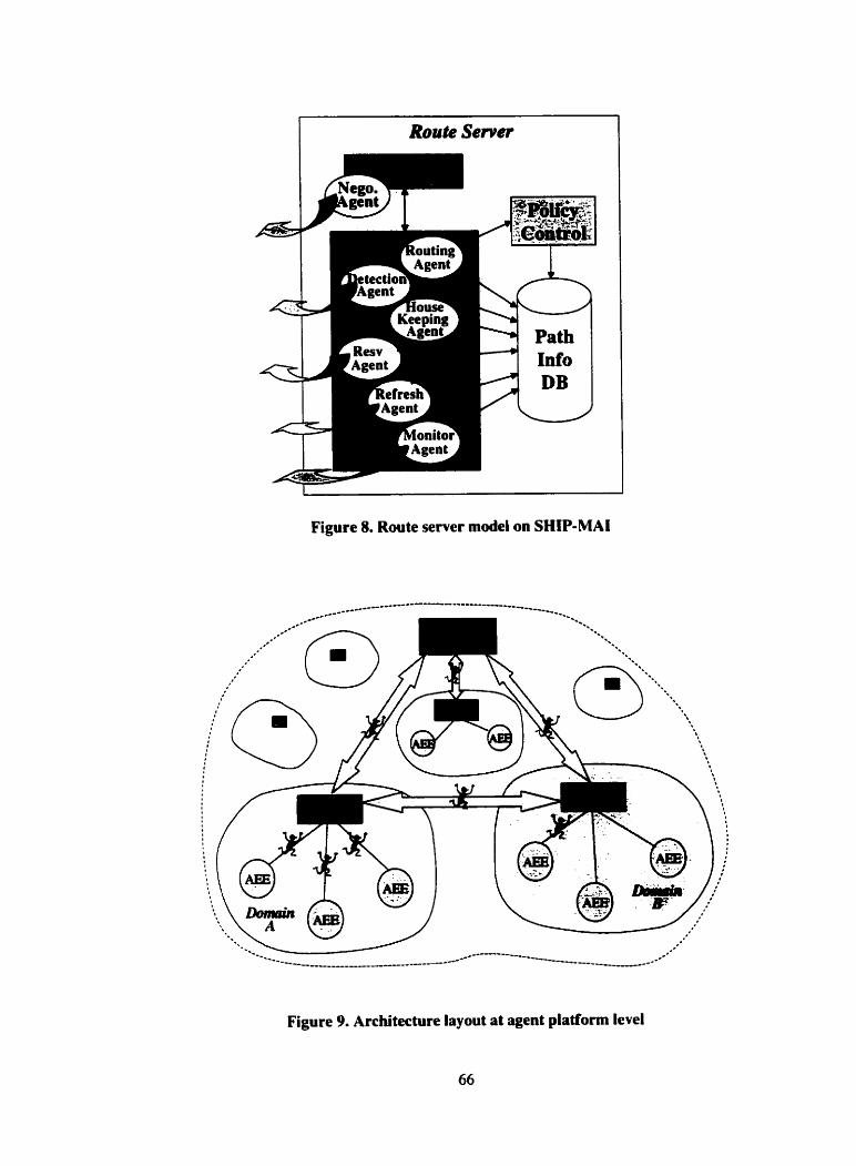
I--- Route Server
Figure 8. Route server m d e l on SHIP-MAI
Figure 9. Architecture layout at agent platform level
Route server's AEC is in charge of the management of agents and AEEs in its
controlling domain. Routes and end-systems of the network need to provide the services
of AEE for the agents to execute their tasks at their locations. That means the AEE
environment needs to be set on top of the routen and the end-systems. Al1 the agents that
perform the functionality of the route server. as we discussed earlier in this chapter, are
created by route servedAEC. They use the facilities and services provided by the SHIP-
MAI platform for migration, communication and execution. Agents cm migrate from the
route server to the target routen or end-systems. or from one router to another. When the
migration is between different domains, the agents go through the SSL connection for
security concem. This service is also supported by SHIP-MAI as we described in the
previous section.
It needs to point out that, although the PRS resides at a higher level over DRS in
the viewpoint of the application - our QoS management architecture. the PRS' AEC is
just a peer of DRS' AEC while seen from the agent platform level. The controlling
domain of PRS'AEC overlaps (covers) dl the domains of DRS' AEC. Figure 9 depicts
the layout of the architecture seen from agent platform level.
CHAPTER 5
DESIGN AND IMPLEMENTATION
In this chapter, we explain the design and implementation of the QoS
management mode1 of our architecture.
The establishment steps of a new QoS session c m be grouped into two phases.
The first phase is the negotiation process. It is further divided into two stages: The
negotiation between sender and receiver. and the negotiation between application and
network. When the negotiation phase is finished, an end-to-end route from the sender to
the receiver is srlected. The second phase is the actual resource reservation. Ln this phase
the reservation process makes the actual reservation with the physical resources dong the
selected route. The idea of QoS establishing phases was suggested in [7].
5.1 Negotiation Phase
The negotiation phase is hinher divided into two stages. Fint is the negotiation at
application level. In this stage the sender and receiver negotiate about the transmission
qualitirs so as to reûch an agreement on QoS specification. Second stage is the
negotiation at network level. in this stage. QoS routing is perfomed to see if the network
resources or conditions c m satisfy such agreed quality specification.
5.1.1 Negotiation between sender and receiver
In the first stage of the negotiation, the receiver (e.g., user of multimedia
application) and the sender (multimedia application) negotiate with e x h other based on
data transmission requirements of the application and the desire and capabilities of the
user. If the negotiation succeed, it means that they reach an agreement on certain QoS
pararneters. The QoS parameters of the application usually involve qualitative
parameters, such as audio and video quality, and quantitative parameters. such as
bandwidth requirement, trame rate, presentation delay and jitter rate, etc. Different value
of a parameter represents different transmission quality. in addition. the application may
state the cost it charges for different quality. At the user side. user States the capabilities
of hisher site to receive the data, and hisher preferences in terms of QoS parameters.
These pararneters include the desired quality. network connection capabilities, hardware
capabilities. cost that the user is willing to pay. tirne constraints, and importance factors.
etc. [16]. At this stage, if the user is involved in the negotiation personally. the QoS
parameters that the application presents to the user should be user perceptual. And after
this stage. there should be some QoS parameter mapping mechanism to translate the
parameters to be network perceptual. as we explained in chapter 2.
In our architecture, we leave out this translation by using negotiation agents that
understand the QoS parameters of network level to perform the negotiation on behalf of
the user and the multimedia application. We design to use profiles to keep QoS
parameters for both the application and the user. At sender side. the application profile
lists dl the QoS panmeters that need to be set for the application to transmit the
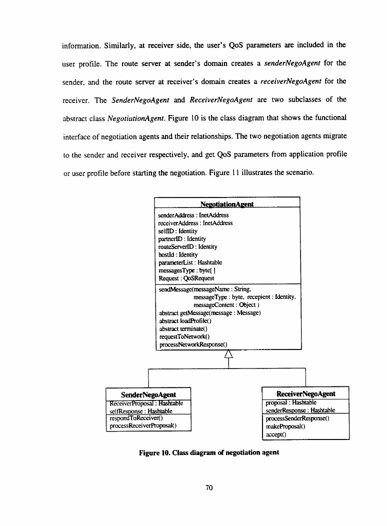
information. Sirnilarly, at receiver side, the user's QoS pararneters are included in the
user profile. The route server at sender's domain creates a senderNegoAgent for the
sender. and the route server at receiver's domain creates a receiverNegoAgent for the
receiver. The SenderNegoAgent and ReceiverNegoAgent are two subclasses of the
abstract class NegotiationAgent. Figure 10 is the class diagram that shows the functional
interface of negotiation agents and their relationships. The two negotiation agents migrate
io the sender and receiver respectively, and get QoS pararneters from application profile
or user profile before starting the negotiation. Figure 1 1 illustrates the scenario.
NwotiationA~ent senderAddress : InetAddress rticeiverAddress : InetAddrcs.~ selm) : Identity partnerID : Identity rout&rverD : Identity hostid : Identity pamnetertist : Hashtablc messagesType : byte[ 1 Request : QoSRequest
sendMessage(messageNamc : String, messageTypc : byte, recepicnt : Identity, messagecontent : ûbjcct )
abstract gctMessage(rnessage : Messilgel ribstract loadRofile() abstnct terminaie() requestToNetwork() process Net wor kRespnse()
/\
SenderNegoAgent RcceiverProposal : Hashtable
ReceiverNegoAgen t proposal : Hashtable senderResponse : Hashtable processSenderResponse() makePruposal() accepta
Figure 10. Clirss diagram of negotiation agent
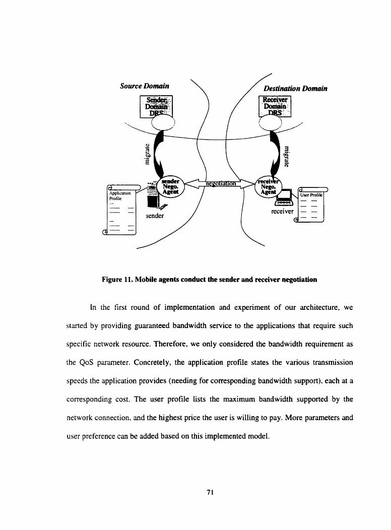
Source Domain \
Figure 11. Mobile agents cooduct the sender and receiver negotiation
In the first round of implementation and experiment of our architecture. we
started by providing guaranteed bandwidth service to the applications that require such
specific network resource. Therefore, we only considered the bandwidth requirement as
the QoS panmeter. Concretely, the application profile states the various transmission
speeds the application provides (needing for corresponding bandwidth support). each at a
corresponding cost. The user profile lists the maximum bandwidth supported by the
network connection. and the highest price the user is willing to pay. More parameters and
user pre ference c m be added based on this implemented model.
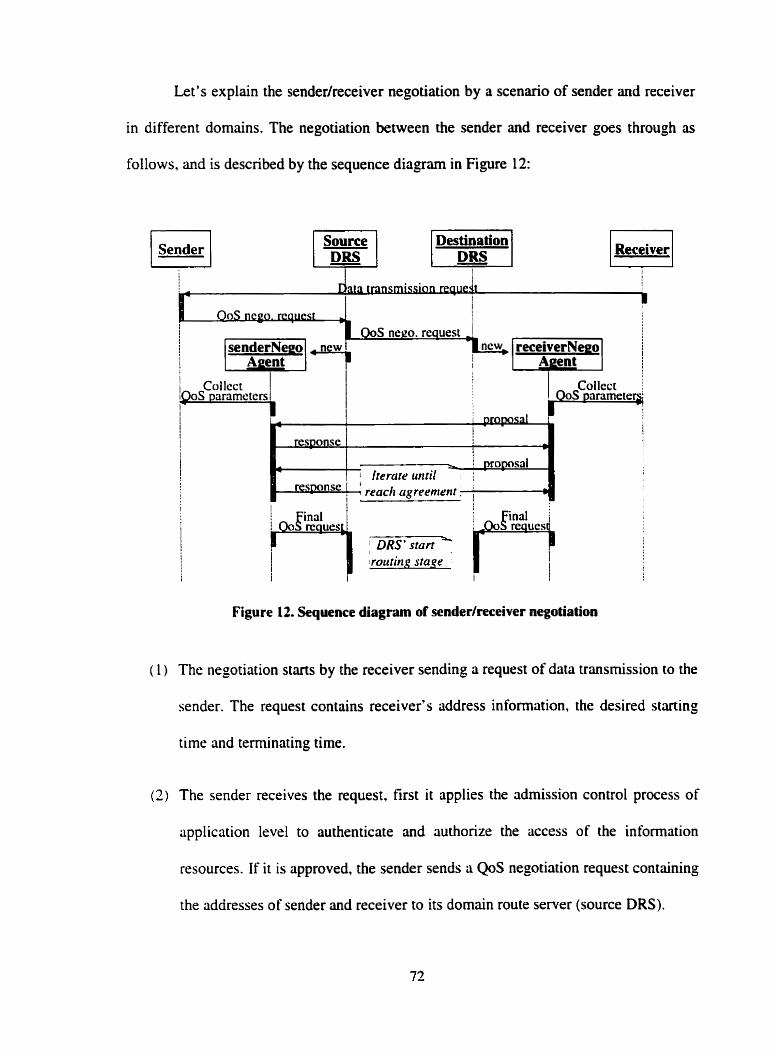
Let's explain the senderlreceiver negotiation by a scenario of sender and receiver
in different domains. The negotiation between the sender and receiver goes through as
foilows, and is described by the sequence diagram in Figure 12:
Destination pl lpesl Receiver n
i n re ues rpn: re ucs 1 ; DRS* stan ' 1 roritirig m g r
j i I i
Figure 12. Sequence diagram of sfndedreceiver negotiation
( 1) The negotiation starts by the receiver sending a request of data transmission to the
sender. The request contains receiver's address information. the desired starting
time and teminating tirne.
( 2 ) The sender receives the request. first it applies the admission conuol process of
application level to authenticate and authonze the access of the information
resources. If it is approved, the sender sends a QoS negotiation request containing
the addresses of sender and receiver to its domain route server (source DRS).
(3) The DRS treats each session request independently. Afier receiving the request.
the source DRS forwards the negotiation request to the DRS of receiver's domain
(destination DRS). In the meanwhile. the source DRS creates a senderNegoAgent,
and sends i t to the sender site.
(4) Sarne as the source DRS, the destination DRS, after receiving the negotiation
request. creates a receiverNegoAgent. and sends it to the receiver site.
(5) At sender and receiver site, the negotiation agent retrieves the QoS parameters
from the application profile or user profile respectively. Consequently, the agents
have the knowledge of the requirements of application or user respectively.
(6) Now the two agents can communicate with each other to negotiate about the QoS
specification. Like the negotiation between two partners in the reai world. the
receiver's negotiation agent sends a proposal to the sender's negotiation agent.
The proposal contains the QoS parameters that the receiver cm support for the
transmission, e.g.. bmdwidth capability. Then the sender's agent finds the
corresponding pararneter in its parameter list which was got from the application
profile, and makes an offer based on the receiver's proposal. The offer contains
the actuai value of the pararneter that is available from the sender and matches the
user's capability, and the cost the sender charges. The receiver's agent may
riccept. reject the sender's offer, or make a funher proposal. The negotiation
cames on till the agreement is reached or two parties fail to reach an agreement.
The agreement is the best match between what the application c m provide and
what the user is capable to support under the user's price limitation. Let's explain
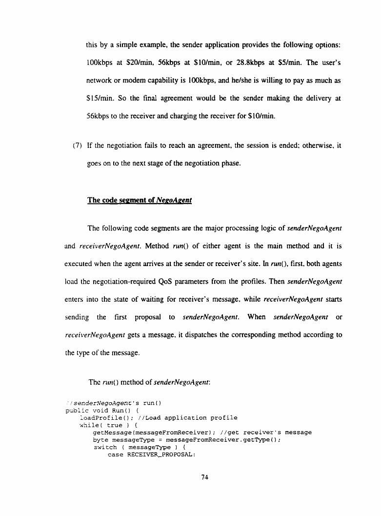
this by a simple example, the sender application provides the following options:
LOOkbps at $20/min, 56kbps at $lO/rnin, or 28.8kbps at $5/min. The user's
network or modem capability is IOOkbps, and helshe is willing to pay as much as
$15/min. So the final agreement would be the sender making the delivery at
56kbps to the receiver and charging the receiver for SlO/min.
(7) If the negotiation fails to reach an agreement. the session is ended: otherwise. it
goes on to the next stage of the negotiation phase.
The code segment of NegoApent
The following code segments are the major prcn-essing logic of senderNegoAgent
and receiverhregoAgent. Method riin() of either agent is the main method and it is
executed when the agent arrives at the sender or receiver's site. in nin(). first, both agents
load the negotiation-required QoS parameters from the profiles. Then senderNegoAgent
enters into the state of waiting for receiver's message, while receiverNegoAgent siarts
sending the first proposal to senderNegoAgent. When senderNegoAgent or
rrceiverNegoAgent g t s a message, it dispatches the corresponding method according to
the type of the message.
The niri() method of senderNrgoAgenf:
.' / sende,rNegoAgent ' s run ( 1 public void R u n ( ) {
loadProfile() ; //Load application profile : h i l e ( true ) {
getMessage(rnessageFromReceiver); //get receiver's message byte rnessageType = rnessageFromReceiver.getType(); switch ( messageType ) (
case RZCEIVER-PROPOSAL:
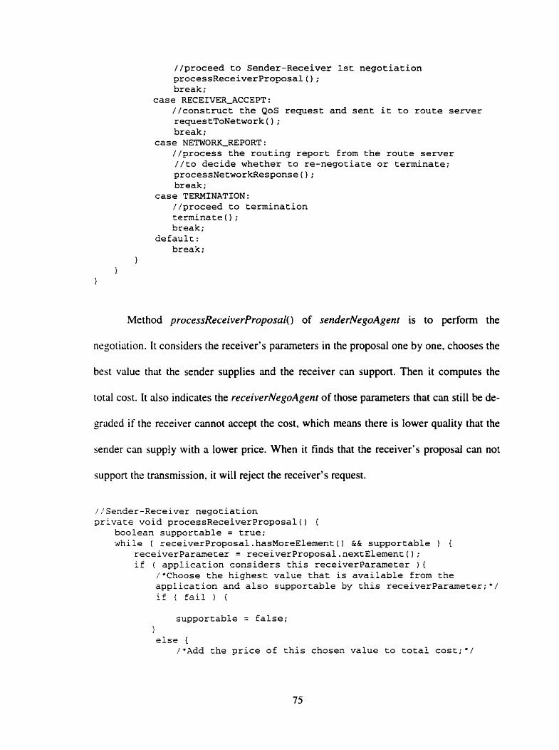
//proceed to Sender-Receiver 1st negotiation processReceiverProposal(); break;
case RECEIVER-ACCEPT: //construct the QoS request and sent it to route server requestToNetwork ( ) ; break;
case NETWORK-REPORT: //process the routing report £rom the route server //to decide whether to re-negotiate or terminate; processNetworkResponse0; break;
case TERMINATION: //proceed to termination terminate ( ) ; break;
default: break;
1
Method processReceiverProposnl() of senderNegoAgent is to perfonn the
negotiation. It considers the receiver's parameters in the proposal one by one. chooses the
best value that the sender supplies and the receiver cm support. Then it cornputes the
total cost. It also indicates the receiverNegoAgent of those parameters that c m still be de-
graded if the receiver cannot accept the cost. which means there is lower quality that the
sender c m supply with a lower price. When it finds that the receiver's proposal can not
support the transmission, it will reject the receiver's request.
lisender-Receiver negotiation private void processReceiverProposal() {
boolean supportable = true; while ( receiverProposal.hasMoreElement() && supportable ) (
receiverpaxameter = receiverProposal.nextE1ement(); if ( application considers this receiverparameter ) {
/*Choose the highest value that is available from the application and alço supportable by this receiverParamerer;*/ if ( fail ) {
supportable = false; 1 else (
/*Add the price of this chosen value to total cost;*/
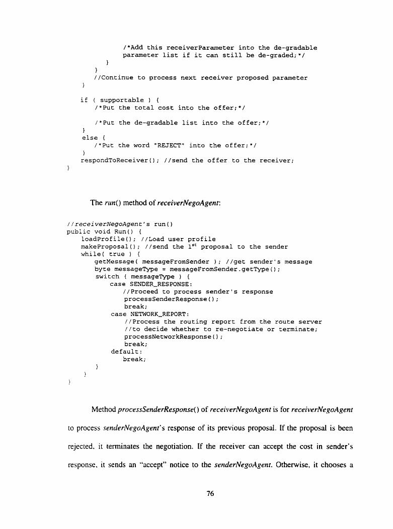
/*Add this receiverparameter into the de-gradable parameter list if it can still be de-graded;*/
1 1 //Continue to process next receiver proposed parameter
1
if ( supportable ) { /*Put the total cost into the offer;*/
/*Put the de-gradable list into the offer;*/ 1 else (
/*Put the word "REJECT" into the offer;*/ } respondToReceiver(); //send the offer to the receiver;
1
The nin() method of receiverNegoAgent:
/ / recei verNegoAgent ' s run ( ) public void Runo (
loadProfile(); //Load user profile makeProposal(); //send the lSC proposal to the sender while( true ) {
getMessage( rnessageFromSender 1 ; //get sender's message byte messageType = rnessageFromSender.getType{); switch ( messageType ) {
case SENDER-RESPONSE: //Proceed to process sender's response processSenderResponse ( ) ; break;
case NETWOEZK-REPORT : //Process the routing report from the route server //to decide whether to re-negotiate or ceminate; processNetworkResponse ( ) ; break;
default: break;
Method processSenderResponse() of recei~wrNegoAyent is for receiverNegoAgenf
to process srnderNegoAgenrTs response of its previous proposai. If the proposal is been
rejected. it teminates the negotiation. If the receiver c m iiccept the cost in sender's
res ponse, it sends an "accept" notice to the seriderhregorlgrnt. Otherwise, it chooses a
parameter from the de-gradable-parameter list, and send a further proposa1 saying "Give
me a lower price by de-grading this parameter."
private void processSenderResponse() { if ( sender "REJECT" the proposal )
terminate ( ) ; else {
if ( receiver can accept the cost )
accept(); //send "ACCEPTn to sender else {
/*Choose a parameter from the de-gradable list according CO receiver's willingness;*/
if ( de-gradable list is empty )
//i.e., no parameter can be de-graded any more teminate ( ) ;
else { /*Construct a furthex Proposa1 to ask the sender CO de- grade a parameter;*/
rnakeProposal0; //send the further proposal to sender 1
1 1
1
5.1.2 Negotiation with the router server
After the sender and receiver agreed upon a final QoS specification. the
negotiation phase curies on to the next stage, i.e.. negotiate about the QoS with the route
server. to see if the network can support the required QoS. To do this, the route server
will perfonn QoS routing to select an end-to-end path from the sender to the receiver that
can siitisfy the required QoS specification. If such path is successiu1ly allocated, it mems
the QoS request cm be supponed by the network. Following steps and Figure 13 descnbe
the sequence of the routing process of a session whose sender and receiver are in
di fferent domains.
(1) The negotiation agent at sender side sends a message as a QoS routing request to
the source DRS where it was dispatched. The message carries the QoS
specification that contains the QoS requirements. time specification and session
addresses, etc. In next section, we'll describe the details about the information in
QoS request.
(7) In the meantirne. the negotiation agent at the receiver side also sends the s m e
QoS request to the destination DRS.
(3) After received the messages, the two DRSs create a routing agent of their own
respectively.
(4) In the source DRS, the routing agent begins the intra-domain routing by
connecting to the path information database of its site. Based on the QoS request
and the path information of PIDB which shows the availability of paths in the
domain. the routing agent selects the best path from sender to an outgoing
boundary router towards the receiver. Then it updates the resource usage
information related to the selected path in the PD6 as temporary reservation. so
that the resource will not be used to accommodate other QoS requests. As to the
detail of the design of PIDB and the routing algorithm (i.e.. how does the routing
agent get the best path), we will describe later.
( 5 ) The routing agent at the destination DRS performs the intra-domain routing in the
samr way as the routing agent in source DRS. It determines the best path from an
incoming boundary router to the receiver, and makes the temporary reservation in
the PIDB for the request.
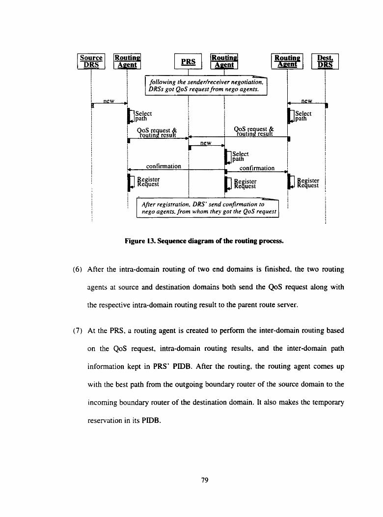
! 1 I
following the senderheceiver negotiation, DRSs got QoS request /rom nego agents.
Select
new i I
Select l i path I
I confirmation
1 confirmation
W:$"
1 Alrer regisrr<rtio>l DRS send c&firwtarion to- nego agents. from whom they got the QoS request
Figure 13. Sequence diagram of the routing proces.
(6) After the intra-domain routing of two end domains is finished. the two routing
agents at source and destination domains both send the QoS request dong with
the respective intra-domain routing result to the parent route server.
(7) At the PRS. a routing agent is created to perform the inter-domain rouùng based
on the QoS request, intra-domain routing results, and the inter-domain path
information kept in PRS' PIDB. After the routing, the routing agent cornes up
with the best path from the outgoing boundary router of the source domain to the
incorning boundary router of the destination domain. It also rnakes the ternporary
reservation in its PIDB.
(8) Then the routing agent of the PRS notifies the routing agents of source DRS and
destination DRS that the inter-domain is done successfÙlly.
(9) Finally, the three routing agents register the corresponding request, as a new
session expecting to start at some specified timr, in their PIDB respectively.
If the routing goes through successfully as we listed from step ( 1 ) to (9). alter the
QoS request is registered in PLDBs. the two end domain DRSs will send confirmations to
the corresponding negotiation agents at sender or receiver site.
In the cases that any one of the three routing agents may find out that the network
conditions could not satisfy the QoS request, the corresponding negotiation agents will be
notified by the routing agent of their respective domain. We propose two approaches to
handle such situation based on the strictness of the QoS request. If the QoS requirement
werr strict and must not be violated. like the hard real-time applications. the routing agent
would reject the request, notify other routing agents of this request in order to tear down
the temporary reservation if it had already made. Then the routing agents at DRSs would
notify the negotiation agents about the network condition. The negotiation agents could
make the decision either to further the negotiation or just terminate the session. For other
softer requests. like the ordinary multimedia applications whose requirements are not
very critical. the routing agents would try their best to satisfy the requirements with
somewhat lower standards. As soon as the network condition turns better, that the
previous request cm be satisfied. the routing agents will adapt the session to the path that
c m satisfy the original QoS request. In this case, the negotiation agents would be notified
and need to make some pnce adjustrnent according to the actual quality the session gets.
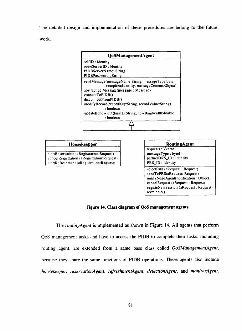
The detailed design and implementation of these procedures are belong to the future
work.
QoSManagementAgent selflD : ldentity routeServerID : ldentity PlDBServerNarne: String PIDBPzissword : String sendMessage(messageName:S tring. messageType: byte.
recepient:Identity, messageContent:Object) abstrac t getMessage(message : Message) connectToPIDB() disconnectFromPIDB() modifyRecord(recordKey:String. recordValuc:String)
: boolean updateBandwidth(linkID:String, newBandwidth:doublc)
: boolean
Housekeepper
messagrType : byte[ 1 partnerDRS-ID : Idcnrity PRS-ID : ldentity
sclectPath (aRequest : Requesr) sendToPRS(aRequest: Request) notifyNcgoAgent(notificzition : Objeçt) cancelRequest (aRequest : Rcquest) rcgisteNewSession (aRequest : Request) terminate0
Figure 14. Class diagram of QoS management agents
The routingAgent is implemenred as shown in Figure 14. Al1 agents that perform
QoS management tasks and have to access the PIDB to complete their tasks. including
routing agent. are extended from a sarne base class cdled QoSManagemmtAgenr.
because they share the sarne functions of PtDB operations. These agents also include
hvitsekeepcr. reservcitionAgenr, refreshmrnrtlgent. JrtecfionAgent. and nzonitorAgent.
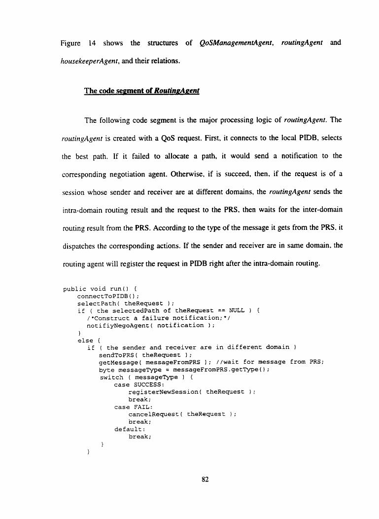
Figure 14 shows the structures of QoSManagemenrAgent, routingAgent and
IiousekeeperAgent, and theû relations.
The code segment of RoutingAgent
The following code segment is the major processing logic of ro~itingAgent. The
rouringAgenf is created with a QoS request. First, it connects to the local PIDB. selects
the best path. If it failed to allocate a path, it would send a notification to the
corresponding negotiation agent. Oiherwise. if is succeed, ihen. if the request is of a
session whose sender and receiver are at different domains. the roirtingAgent sends the
intra-domain routing result and the request to the PRS. then waits for the inter-domain
routing result from the PRS. According to the type of the message it gets from the PRS, it
dispütches the corresponding actions. If the sender and receiver are in same domain. the
routing agent will register the request in PiDB right after the intra-domain routing.
public void run() { connectToPIDB ( ) ; selectPath( theRequest ) ;
i f ( the selectedpath of theRequest == NüLL ) { /*Construct a failure notification;*/ notifiyNegoAgenc( notification 1 ;
1 else E
if ( the sender and receiver are in different domain 1 sendToPRS ( theReques t 1 ; getMessage( messageFrornPRS ) ; //waic for message from PRS; byte messageType = messageFrornPRS.getType0; switch ( messageme 1 {
case SUCCESS: registerNewSession( theRequest ) ;
break; case FAIL:
cancelRequest( theRequest 1 ; Dreak;
default: break;
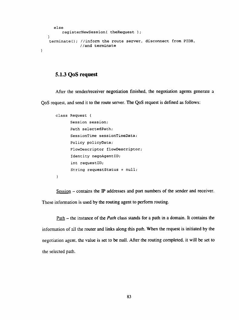
else registerNewSession( theRequest ) ;
1 terminate(); //inform the route server, disconnect from PIDB,
//and terminate
5.1.3 QoS request
Aftrr the sendedreceiver negotiation finished, the negotiation agents generate a
QoS request, and send it to the route server. The QoS request is defined as follows:
class Request {
Session session;
Path selectedpath;
SessionTime sessionTimeData;
Policy policyData;
FlowDescriptor flowDescriptor;
Idencity negoAgentID;
int requestID;
String requeststatus = null;
1
Session - contains the IP addresses and port numbers of the sender and receiver.
Thrse information is used by the routing agent to perform routing.
Path - the instance of the Pafh class stands for a path in a domain. It contains the -
information of ail the router and links dong this path. Whrn the request is initiated by the
negotiation agent. the value is set to be null. After the routing completed. it will be set to
the selected path.
SessionTime - is the class that contains the desired start tirne and termination
time of the session. This information is used to start and tear the actual resource
reservation for the request.
Policv - carries information that will dlow the route server to decide whether an
iissociated reservation is administntively permitted.
FlowDescrbtor - contains flow-specification and filter-specification.
flow-specification specifies the desired QoS, which is the criteria of path selection.
Filter-specification is used when making the reservation. It indicates the set of data
packets to receive the QoS defined by the flow_specification.
Also. in the request. it needs to maintain the Identity of the negotiation agent
who generates the request. The requeststatus indicates the current status of the request.
siich as. "new" (new request, not actually reserve resources yet). "reserveâ" (the
resources are reserved. ready to start), or "active" (the session is currently carrying on).
5.2 Path Information Database and Routing Algorithm
As being mentioned throughout the discussion, the path information database is
an essential component of Our QoS architecture. The PiDB is designed be used for
dynamically maintaining the path information of a particular domain, such information is
the base of QoS routing. and resource reservation. Also PiDB kerps the records of
registered sessions from the time the request is made till the time the session is expired.
The purpose of this is to de-couple the actual resource reservation phase from the
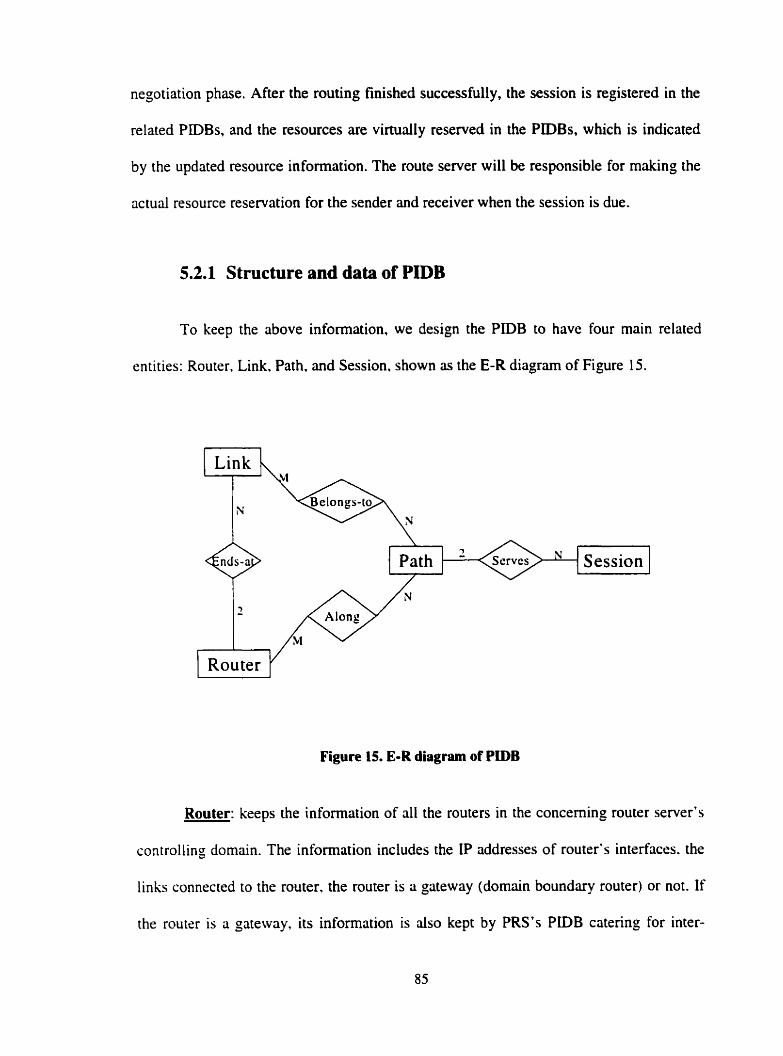
negotiation phase. After the routing finished successfully, the session is registered in the
related PIDBs. and the resources are virtually reserved in the PIDBs, which is indicated
by the updated resource information. The route server will be responsible for making the
actual resource reservation for the sender and receiver when the session is due.
5.2.1 Structure and data of PIDB
To keep the above information, we design the PIDB to have four main related
entities: Router, Link. Path, and Session, shown as the E-R diagram of Figure 15.
Figure 15. E-R diagram of PIDB
3 " '
Router: keeps the information of al1 the routers in the conceming router server's
controlling domain. The information includes the IP addresses of router's interfaces. the
links connected to the router. the router is a gateway (domain boundary router) or not. If
the router is a gateway. its information is ais0 kept by PRS's P D B catering for inter-
t
Session
domain routing. And we use the address of the router interface that connects the router to
the route server as the identification of the router in the database.
Link: keeps the information of al1 the point-to-point links in the domain, which - includes the identification of the link (assigned by the administrator), two end router
addresses of the link. and the identifications of al1 the paths that consist of this link. It is
clear that an end-to-end path consists of a sequence of links and a link can be shared by
more than one path. And in order to reflect the resource usage and capacity of the link,
P D B dynarnically keeps the residital-bandkvidtli (rb) of the link. As mentioned earlier,
we only consider the bandwidth parameter as the experimental indicator in the first round
of implementation.
Path: keeps the information of al1 the vaiid paths that can be potentially used for - QoS routing in the domain. The path information includes, two end addresses. the
identifications of dl the links along the path. the addresses of al1 the routers along the
path. the hop count of the path, and the bandwidth availability of the path which is
indicated by the mnrimum-reservable-bandbvidth (mrb), and civerage-residitul-band,vidfh
(urb). These two bandwidth parameters are computed from the bandwidth data of dl the
links along the path as:
mrb, = min {ïbii I 1, E p}
trrb, = (Lrba ) l k
Wherr mrbp and cwb, stand for the rnrb and nrb of poth p. and p = { l l,..., lk]: Il is
<i li~ik belorzg to pnth p: ïbri is the residirol bandwiùth of link 1,
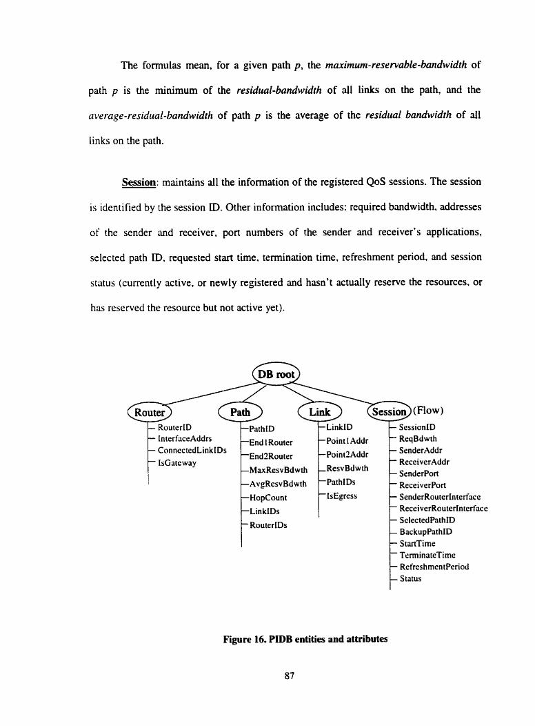
The formulas mean, for a given path p, the maximum-reservable-bandwidth of
path p is the minimum of the residual-bandwidth of al1 links on the path, and the
average-residrial-bandwidth of path p is the average of the residual bandwidtlz of al1
links on the path.
Session: maintains al1 the information of the registered QoS sessions. The session
is identified by the session ID. Other information includes: required bandwidth. addresses
of the sender and receiver. port numbers of the sender and receiver's applications,
selected path ID, requested start time. termination time. refreshment period. and session
status (currently active, or newly registered and hasn't actually reserve the resources. or
has reserved the resource but not active yet).
tn tcrfaceAddrs End 1 Router Point 1 Addr ReqBdwth Connec tcdLinkIDs SenderAddr
ReceiverAddr SenderPort
SelectedPathID Bac kupPathID StimTirne TenninatcTimc Refres hmen tPeriod S tatus
Figure 16. PIDB entities and attributes
The experimental PIDB is setup using LDAP Netscape directory server. Figure 16
shows the database structure and the attributes of the entities.
5.2.2 The efficiency consideration of PIDB
When we started to design the database, we had several concens which we think
are wonh some discussion here. They are of the efficiency and scalability of such
database. That is. the overhead of creating and maintaining the PIDB. and PIDB must
scde well as the network grows. The fiat question is how to find dl the paths in a
domain or between a pair of endpoints? We have to find an aigorithm to solve this
problem brfore we c m move on. And it seems. from the first sight. that the number of
such paths would be too large to be held. Moreover. the topology of the network changes
dynamically and unpredictably. If one router or one link failed to work well. the database
needs to update al1 the paths that are affected. which could be a very time consuming
task. Funher, to maintain such database may generate a lot of network traffics itself since
it needs to frequently coilect the link level data.
These problems have also been considered in SAAM project. In SAAM project,
they use an algorithm that performs a recursive search to find dl the valid paths [El. The
authors point out that the number of paths won? be unreasonably large for a single
domain. like an AS. since the database contains only mfid paths-those that are loop free
and have a hop count less than a particular bound. H- mu^. H-mm is set not to exceed 8
to 10, because it is believed that it'd be bad network design if a useful path has to traverse
more than 8(10) hops in one single AS. Also, as a result, the average number of valid
paths for a particular (source, destination) pair is not very large, iuound 20 for a 28-node
AS. Therefore, the server can quickly find the suitable path for a flow request even if the
total number of paths is large. Of course, large memory space is required if the total
number of paths in the database is big. But memory is cheap today and won? be the
problern. Further, the experiment result shows that it takes only 3 seconds for a JAVA
implementation on a low 2OûMhz PentiumPro to compute the whole PB of a 28-node
network AS for the first time. After that. if a link fails. only a small number of paths need
to be updated. Therefore, based on these researches, we cm conclude that the PIDB c m
be set up and maintained efficiently.
5.2.3 Path selection algorithm
The goal of the routing algorithm is to find a feasible path. if any, and to select
one that achieves efficiency of overall resource utilitation if more than one feasible path
is rivailable. The feusible path is the path that can satisfy a set of QoS constraints. like
bandwidth. delay, andfor other requested QoS parameten. As mentioned before. we use
pre-computed paths instead of routing on-demand. The pre-computed path information is
maintûined dynarnically in the PiDB. This approach reduces the QoS routing tirne to a
great extent cornparing with routing on-demand, because the path information is kept
handy in PiDB. The routing is just to select a path from the database. Now we discuss the
path selection aigorithm of our architecture.
There are some path selection algorithms that are various at giving different
preference of resource consumption and consequently have different performance under
different network conditions as we discussed earlier in chapter 2. In out architecture, we
design the QoS path selection aigorithm used by the routing agents based on the widest-
shonest path algorithm. The widest-shortest path is the path with minimum hop count
among ail feasible paths and if there are several such paths. it is the one with the
maximum reservable bandwidth, or if there are severai such paths with the same
bandwidth. it is randomly chosen from them. This algonthm gives higher priority to
limiting the hop count than to balancing the network load, and it is experimented to have
better performance when the network load is heavy [ 3 ] .
To improve the algorithm to put more weight on balancing the network load. we
modib the algorithm by adding another path parameter, average-residliul-bandlvidth, for
every path, as mentioned in the previous section. From dl the feasible paths, the path
selection algorithm considers the hop count first. then the second factor is average
reservable bandwidth, by this way we put some consideration on baiancing the network
load after finding the shortest feasible paths. The alprithm is as follows:
( 1) Find al1 the feasible paths for the request, that is, find dl the paths whose rriar-
resenyciblr-band~vidthth is greater or equal to the bandwidth requirement of the
request:
( 2 ) If more than one such path is available. choose the one with the minimum hop
counr:
(3) If more than one such path is available, then the one with the maximum average-
residual-bandwidth is selected.
(4) If there are more than one such path is available, just randornly choose one from
them.
Reservation Phase
After the negotiation phase, the resources are reserved temporarily in the PIDB. In
the reservation phase. route server makes the actual resource reservation with the related
routers and end-systems. and sending confimation to the sender and receiver.
In our architecture. the reservation time is de-coupled from the time when the
request is made. which especidly benefits the advance reservations. in which case. the
sender and recriver only need to make the request once when they start the negotiation,
then the request is held in the PIDBs of related route servers before the actual reservation
is made. and the router server will handle the actual reservation for thern. Consequently,
the routers are relieved from the memory burden of storing the states of advance
reservation.
Every route server is in charge of reserving the resource with the related routers or
hosts that are in its controlling domain. That is, if the sender and receiver are in different
domains. the source DRS and destination DRS make the reservation with routers and
sender or receiver host along the path segments in the two end domains respectively,
while the PRS is responsible for the reservation along the path segment from the outgoing
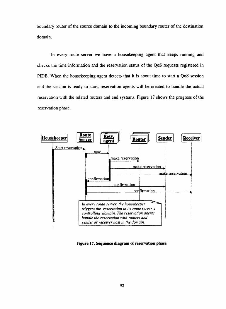
boundary router of the source domain to the incoming boundary router of the destination
domain.
In every route server we have a housekeeping agent that keeps running and
checks the time information and the reservation status of the QoS requests registered in
PiDB. When the housekeeping agent detects that it is about time to start a QoS session
and the session is ready to start, reservation agents will be created to handle the actual
reservation with the related routers and end systems. Figure 17 shows the progress of the
reservation phase.
Resv. lF=JJ
controlling domain. The reservarion agents haridle the reservation with routers and sender or receiver host in the domain.
Figure 17. Sequence diagram of reservation phase

The problem is how the reservation agents actuaily handle the reservation. People
may ask that why you don't simply make use of RSVP protocol to make the reservation?
So. we need to answer this question first before we describe our reservation approaches.
5.3.1 Why can't we make use of RSVP?
Firstly. RSVP uses Path message to find the path for transmitting the data
packets, at every crossed node of the Path niessage, RSVP process invokes the local
routing protocol to find the next hop of the data packets. But with our QoS management
approach. the route of the data packets is iilready known before making the reservation.
so there is no need for such Path message.
Secondly. in RSVP, the Rem messugr which is responsible for making the
reservation is triggered at receiver side by the aniving Pnth messuge. the Resv message is
directed by the state in the routers set by the Path message to Follow the reverse route of
the data packets. If there were no Parh message in our approach, there would be no Resv
niessnge.
Thirdly. the information that contained in the P d 1 and Resv messages is known
by the route server after the negotiation phase. Thus, it is not efficient to still let the
sender and receiver to handle the reservation themselves, which is the rule of RSVP.
Founhly. once we design to let the route server to be in charge of the resource
reservation. the reservation request is generated by the route server rather than the
receiver as in RSVP, which means the reservation procedure of RSVP in network nodes
is apparently cannot be used, since the reservation process and reservation messages that
invoke it are both different.
5.3.2 Design of the resource reservation approaches in our
architecture
We design the reservation approach using the ideas of active network as we
discussed in chapter 2. namely. discrete approach and integrated approach.
First proposed approach: Discrete approach
One approach of active network is referred as discrete approach, in which the
program that performs the cornpuration on the messages is separated from the message.
The network applications would first inject their customized processing programs into the
required routen, then they send their data messages through such "programmable" nodes
much the same way as they do for ordinary transmission. The pre-injected programs will
be dispatched to process the messages. The messages are rnaintained the packetkell
format. Guided by this idea, we propose a discrete approach for handling the resource
menration. The approach is illustrated by Figure 18 and explained step by step as
follows:
( 1 ) When the housekeeper agent finds that it is about the time for a registered session
to s tm ( it should leave estimated enough time to rnake the reservation before the
session stms). it will notify the route server to create ii reservation agent.
(2) The reservation agent works at route server site. First it sen& out messages,
which contain the predefined Reservation process. to the related network nodes
(end-systems and routers) dong the selected path of the conceming session. The
Reservation process is stored in these nodes to expect the reservation request
generated from the route server, just like the RSVP daemon expects Pritlt message
and Resv message from some sender and receiver application.
(3) Then the reservation agent constructs Reservation messages containing the
required QoS parameters, like session data. address of the route server, flow
descriptor. and the path information. Each Reservation message targets to one
node on the selected path. The reservation agent sends the Reservation messages
as ordinary IP packets to their target nodes respectively.
(4) When the Reservation message arrives at the target node, its header is examined
and the pre-injected Reservation process is dispatched to operate on the message
contents. set required state and make the reservation with related "build-in"
primitives - classifier and packet scheduler.
(5) After completing the reservation successfully. the Reservation process at every
node sends a Confirmarion message to the reservation agent at the route server.
Othenvise. it will send an Error message to the reservation agent, in which case.
the reservation agent would try the backup path recorded in the PiDB for the
concerning session. We will have more to say about the backup path later in the
section of QoS adaptation.
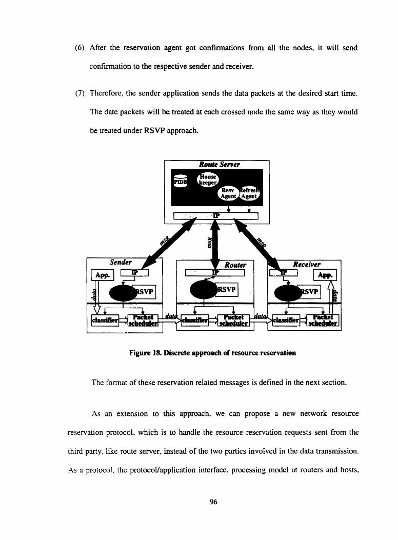
(6) After the reservation agent got confirmations from al1 the nodes, it will send
confirmation to the respective sender and receiver.
(7) Therefore, the sender application sends the data packets at the desired start time.
The date packets will be treated at each crossed node the same way as they would
be treated under RSVP approach.
Figure 18. Dixrete approach of resource reservation
The format of these reservation related messages is defined in the next section.
As an extension to this approach, we cm propose a new network resource
reservation protocol, which is to handle the resource reservation requests sent from the
third Party, like route semer, instead of the two parties involved in the data transmission.
As a protocol, the protocoVapplication interface. processing mode1 at routers and hosts.
and the message fonnat, etc., need to be defined. Then the reservation process can be
stored in the routers and hosts, as the RSVP daemon. In such case. when making the
reservation. the route server only needs to consmct the reservation message. according to
the defined format, and sends the message to the related nodes.
Second proposed approach: Integrated approach
Another approach of active network is narned as integrated approach. in which the
message flowing in the network encapsulates a program and data together. When such
active message arrives at an active node (the node with transient execution environment
for executing the message program), it contents are evaluated and executed. Lead by this
idea. we propose an integrated approach to handle the resource reservation. Instead of
just sending the reservation data to the router, we make the reservation agents migrate to
the related network nodes. The approach is as follows and illustrated by Figure 19.
( 1 ) When the housekeeper agent finds that it is about the time for a registered session
to start. it notifies the route server to create enough nurnber of reservation agents.
The number equals to the number of nodes dong the path. These reservation
agents encapsulate the reservation process as agent code and the required QoS
panmeters ûs the raw data. The format of the data part is the same as the format
of Reservation message in discrete approach.
(2) Each reservation agent is sent to one node on the selected path and only deals
with the resource reservation with this node.
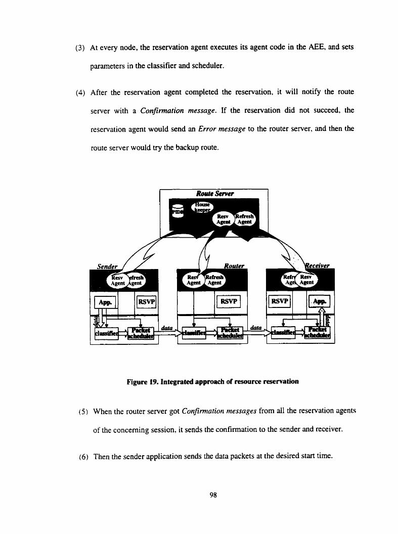
(3) At every node, the reservation agent executes its agent code in the AEE, and sets
parameters in the classifier and scheduler.
(4) After the reservation agent completed the reservation. it will notify the route
server with a Confirmation message. If the reservation did not succeed, the
reservation agent would send an E m r message to the router server. and then the
rouie server would try the backup route.
Figure 19. Integrated appmach of resource rescrvation
( 5 ) When the router server got Confinnation messages from dl the reservation agents
of the concerning session, it sends the confirmation to the sender and receiver.
( 6 ) Then the sender application sends the data packets at the desired siart time.
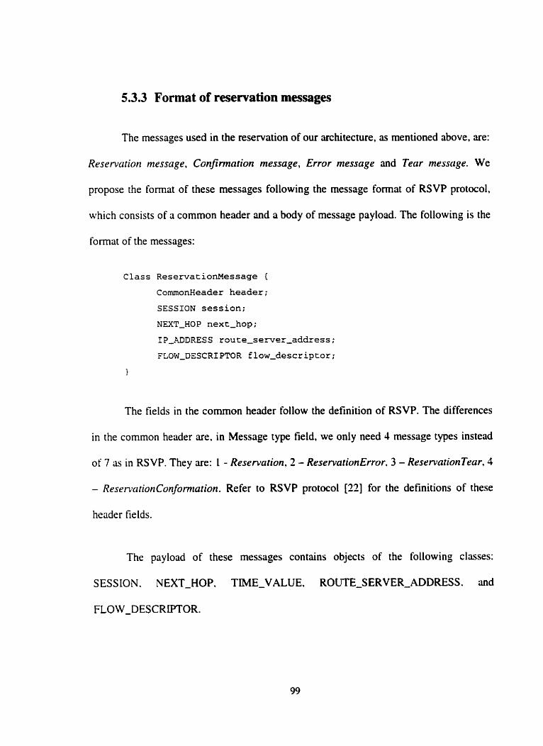
5.3.3 Format of resewation messages
The messages used in the reservation of our architecture, as mentioned above, are:
Rrservation message. Confirmation message, Error message and Tear message. We
propose the format of these messages following the message format of RSVP protocol.
which consists of a common header and a body of message payload. The following is the
format of the messages:
Class ReservationMessage E
ComrnonHeader header;
SESSION session;
NEXT-HOP next-hop;
IP-ADDRESS route-semer-address;
FLOW-DESCRIPTOR flow-descriptor;
1
The fields in the cornmon header follow the definition of RSVP. The differences
in the common header are. in Message type field, we only need 4 message types instead
of 7 as in RSVP. The y are: 1 - Reservution, 2 - ReservationError. 3 - ReservationTeczr, 4
- ReservationConfomzation. Refer io RSVP protocol [22] for the definitions of these
header fields.
The payload of these messages contains objects of the following classes:
SESSION. NEXT-HOP. TIME-VALUE. ROUTE-SERVER-ADDRESS. and
FLOW-DESCRIPTOR.
SESSION - stands as the identifier of a session's reservation. It contains the IP
addresses and port nurnben of the sender and receiver. The information is used to set in
the router to identify the data packets that belong to the specific session. Required in
every message.
NEXT HOP - Carries the iP address of the outgoing interface of the router. on
which the reservation is required. Required in every message.
TME VALUE - Contains the value for the refreshrnent period of the session.
Only required in the Reservation message.
ROUTE SERVER ADDRESS - Carries the IP address of route server from
which this message was originated. The Conformation message is to be sent to this
address. Required in every message.
FLOW DESCRIPTOR - Required in Reservation message. It contains
FLOW-SPECIFICATION and FILTER-SPECIFICATION. FLOW-SPECIFICATION
specifies the desired QoS. and is used to set parameters in the nodeTs packet scheduler.
FILTER-SPECIFICATION. together with the SESSION information, defines the set of
data packets to recrive the QoS defined by the FLOW-SPECIFICATION. It is used to
set parameters in the packet classifier. Data packets that are addressed to s particuiar
session but do not match any FJLTER-SPECiFiCATION for that session are handled as
best-effort traffic.
5.3.4 Reservation refreshment
The housekeeping agent is also responsible for triggenng off the refreshment
agent to refresh the reservation in the related network nodes for the currently active
sessions. As defined in the Reservation message, the TIME-VALLJE contins the length
of the refresh period. This data is set as one of the QoS parameters in every related node.
After this period is expired, if no refreshment instruction is received by the node. the
reservation state will be deleted. Therefore, to maintain the reservation, while the
reservation agent is created to make reservation for a session, a refreshment agent is dso
created with the same knowledge as the reservation agent.
As illustrated in figure 18 and 19. in the discrete approach. the refreshment agent
creates new Reservation messages periodicdly, and sends them to the target nodes the
same way as the reservation agent performs. When the message arrives at the node. the
Reservation process at the node will operate on it to refresh the reservation.
In the integrated approach, at every refresh period. the refreshment agent clones
itself to some nurnber of duplicates. The number is equal to the number of related nodes.
Each replicate agent targets to one node. Then these agents migrate to their target nodes
to refresh the reservation. They work rit the node the same way as the reservation agents
make the reservation.
The code segment of Housekeerrina agent
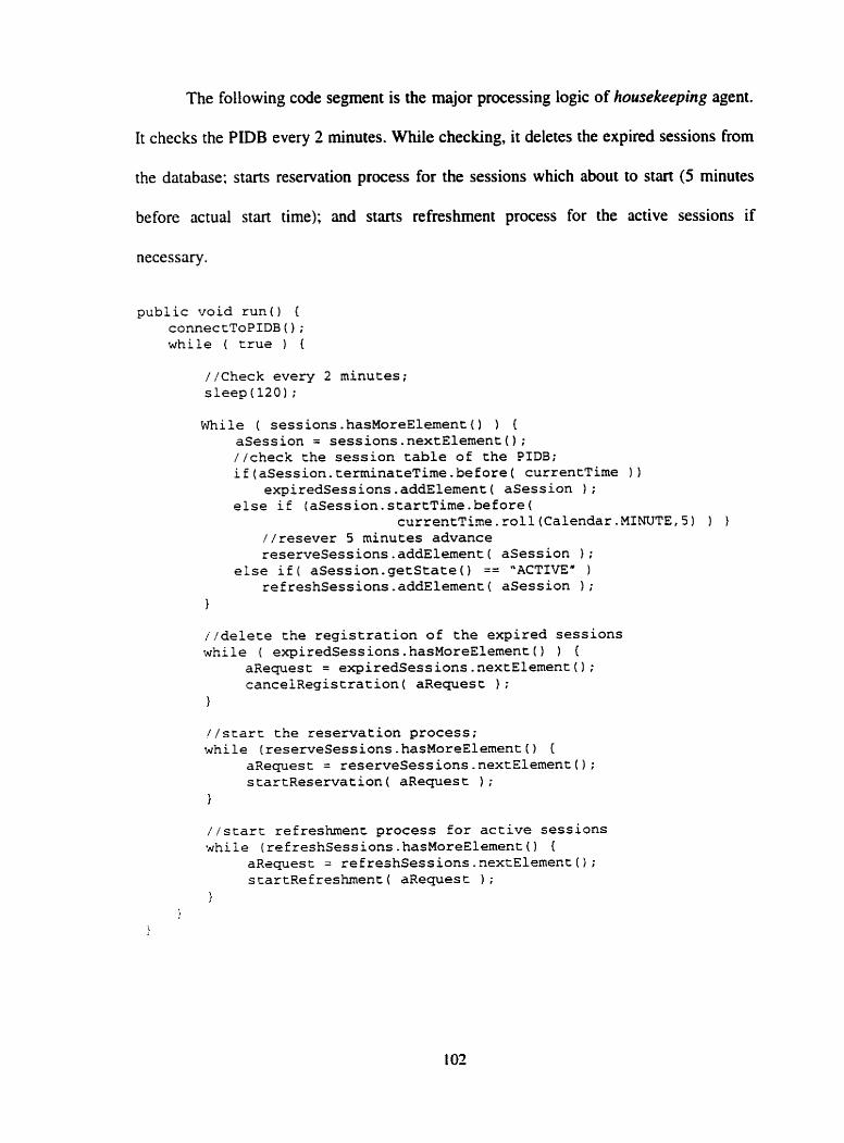
The following code segment is the major processing logic of housekeeping agent.
It checks the PIDB every 2 minutes. While checking, it deletes the expired sessions from
the database; starts reservation process for the sessions which about to start (5 minutes
before actual start time); and starts refreshment process for the active sessions if
necessary.
public void r u n ( ) {
connectToPIDB0; while ( trus ) (
//Check every 2 minutes; sleep (120) ;
While ( sessions. hasMoreElement ( ) ) E asession = sessions.nextElement(); //check the session table of the PIDB; if(aSession.terminateTime.before( currentTime 1 )
expired~essions.addElement( asession ) ;
else if (aSession.startTime.before( currentTime.roll(CaIendar.MINUTE,5) 1 1
//resever 5 minutes advance reserveSessions.addElement( asession 1 ;
else if( aSession,getState() == "ACTIVE" )
refteshSessions,addElement( asession ) ;
1
//delete the registration of the expired sessions while ( expiredSessions,hasMoreEiement() ) {
aRequest = expiredSessions.nextElement0; cancelRegistration( aRequest ) ;
//starc the reservation process; while (reserveSessions.hasMoreEIement() {
aRequest = reserveSessions.nextEIement(); startReservation( aRequest ) ;
//start refreshment process for active sessions while (refreshSessions.hasMoreElemen~0 (
aRsquest = refreshSessions.nextElement0; startRefreshment( aRequest 1 ;
1
QoS Adaptation
The QoS monitoring in our architecture is performed by the monitor agent. The
monitor agent is designed to migrate to the related nodes, such as receiver's site. where it
is responsible for monitoring if the session receives the prornised QoS, and sending the
resuh back to the route server. Then the route server can use the information to decide if
adaptation is required. In the research of this thesis. we haven't corne up with the detailed
working mechanism of the monitor agent. It will be our future work.
In order to ensure that the applications get their requested QoS during the
transmission. cut the adaptation tirne as short as possible. and make highly sufficient use
of the network capacity, we design the QoS adaptation approach of our architecture to be
the combination of re-routing strategy and backup channel stntegy. The proposed
appronch is based on the fact that each QoS request is of different critical level, Le., the
strictness of the requirements of hard real-time applications is quite different from that of
the ordinary multimedia applications. We divide the QoS requests into two classes. the
class of sessions with critical requirements and the class of sessions with non-critical
requirements. The adaptation activities follow the steps shown in Figure 70.
First. during the routing stage of the negotiation phase. we follow the backup
channel strategy. When the routing agent perforrns the path selection at its domain. it also
selects a backup path in addition to the primary path for every request. The related link
and path information in P D B about the backup path is also updated to make sure the path
not be used to accommodate the registration of other QoS sessions.
Second, when the reservation agents perform reservation, it makes the actual
reservation along the primary path. It would not use the backup path unless the
reservation dong the primary path is failed due to some reason. Therefore, the resources
of the backup path would not be occupied until it is activated, since the path can be used
to transfer the best-effort traffics as long as these traffics are preemptive when the backup
path needs to be activated.
Third. after the reservation phase. the backup paths of those sessions that are with
non-critical requirements are cancelled from the PiDBs. The related path and link
information is updated to make the resource free to accommodate other QoS requests.
This arrangement is to address the capacity reduction problem of backup channel
strategy. The problem was the backup paths reduce network capacity because they cannot
be used to accommodate other QoS connections.
Fourth. when a primary QoS connection fails during the transmission, it should be
quickly detected and reported to the route server. if the session on the failed connection is
of critical class. it has a backup path dready. The route server creates reservation agents.
which geet the information of the backup path of the affected QoS session. and make the
resource reservation along the backup path the same way as in the reservation phase.
Then the affected QoS traffics are switched to the new path. Meanwhile the router server
nreds to update the information of al1 paths that are affected by the failed link or router.
And a new backup path should be located for the QoS sessions that need backups. By this
way. the re-connection time is cut to the shortest. If, For the other situation. the session on
the f d e d connection is a non-critical session, the adaptation will start from the re-
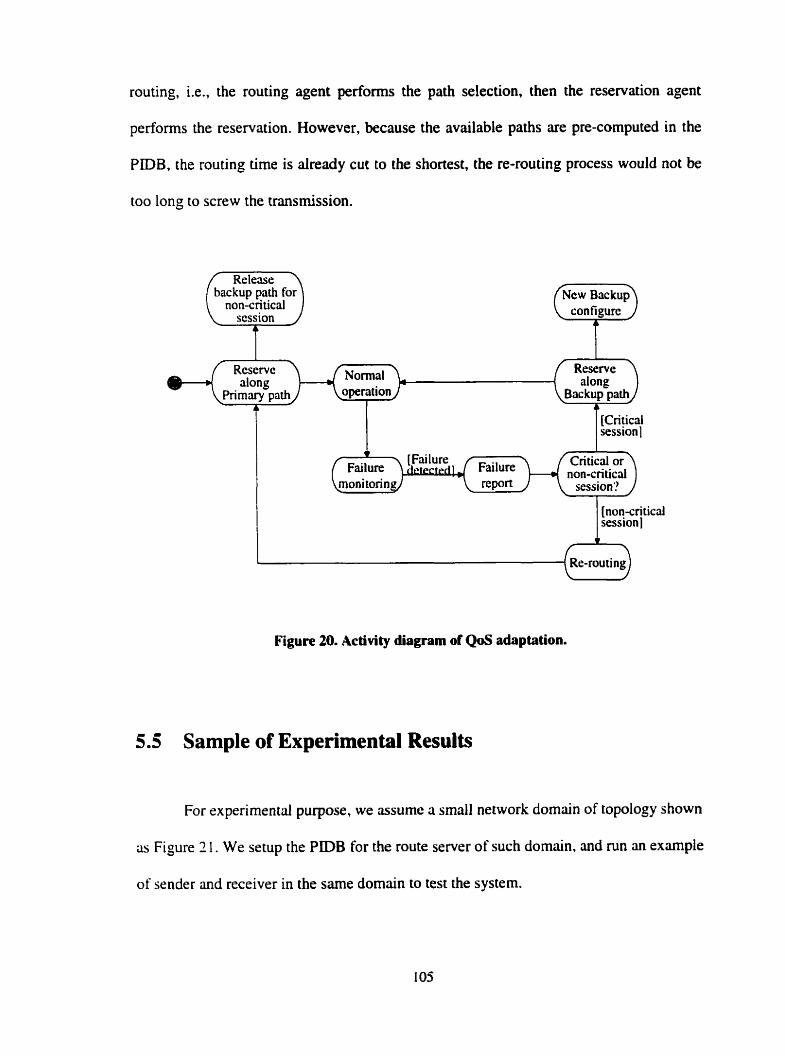
routing, Le., the routing agent performs the path selection, then the reservation agent
performs the reservation. However, because the avdable paths are pre-computed in the
PIDB, the routing time is already cut to the shortest, the re-routing process would not be
too long to screw the transmission.
backup path for non-critical
[Criyical session
[non-criticd session 1
Figure 20. Activity diagram of QoS adaptation.
5.5 Sample of Experimental Results
For experimentd purpose, we assume a small network domain of topology shown
as Figure 2 1 . We setup the PIDB for the route server of such domain. and run an example
of sender and receiver in the same domain to test the system.
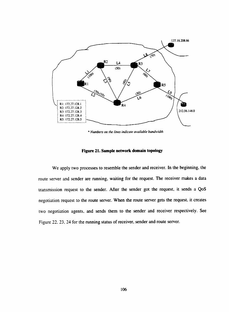
137. t 6.208.66
................................ f RI : t72.37.128.l i
RZ: 172.77.128.1 i I R3: 172.17.128.3 i 8.0
RJ: l ï2.Y. l28.J I
'- ............................ .
" Niunbers on die lines indicare muilable bandwidtit
Figure 21. Sample network domain topology
We apply two processes to resemble the sender and receiver. In the beginning, the
route server and sender are mnning, waiting for the request. The receiver makes a data
transmission request to the sender. After the sender got the request, it sends a QoS
negotiation request to the route server. When the route server gets the request. it creates
iwo negotiation agents, and sends them to the sender and receiver respectively. See
Figure 22.33. 21 for the mnning status of receiver, sender and route server.
Figure 22. Receiver's running status
Figure 23. Sender's running status
1 O7
Figure 24. Route server's running status
The two negotiation agents arrive at the sender and receiver respectively. They
siart by loading the information from the profiles. Then the receiver's negotiation agent
makes the first proposal to sender's negotiation agent. The sender's negotiation agent
responds with an offer. The receiver's agent gets the offer and checks if the receiver c m
iiccept the offer, if not, it will make another proposal. The conversation continues until
the two parties reach an agreement on the QoS specification. Figure 75 shows the
conversation steps.
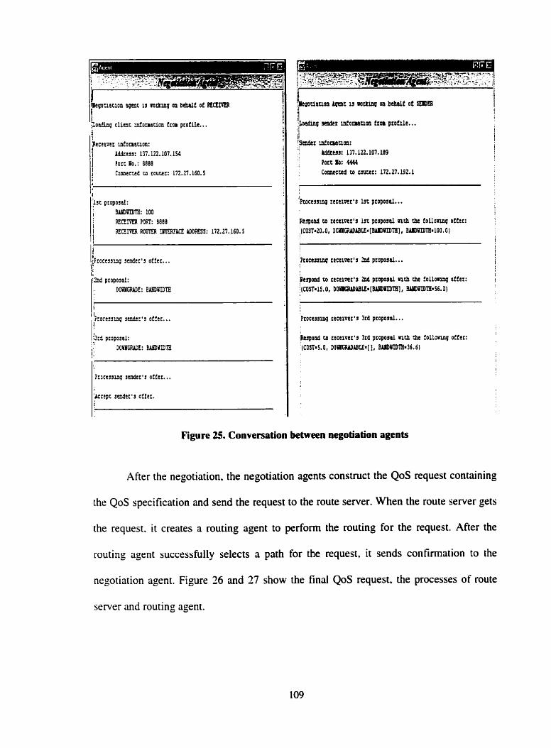
~Recel?tc donauon: :i Iddrtw: L37. I22.107.154
Port PO.: 8888 Comemd UI court:: 112.27.160.S
1
P:ocamg senbcc'~ otftr...
, Porc no: 4444 ' Cmmecctd ro router: 172.27.192.1
Figure 25. Conversation between negotiation agents
After the negotiation. the negotiation agents construct the QoS request containing
the QoS specification and send the request to the route server. When the route server gets
the request. it creates a routing agent to perform the routing for the request. After the
routing agent successfully selects a path for the request, it sends confirmation to the
negotiation agent. Figure 26 and 27 show the final QoS request, the processes of route
server and routing agent.
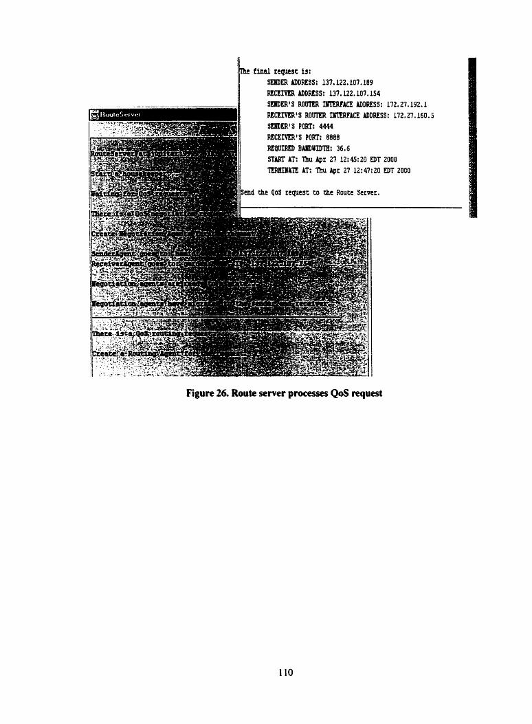
Figure 26. Route semer processes QoS wuest
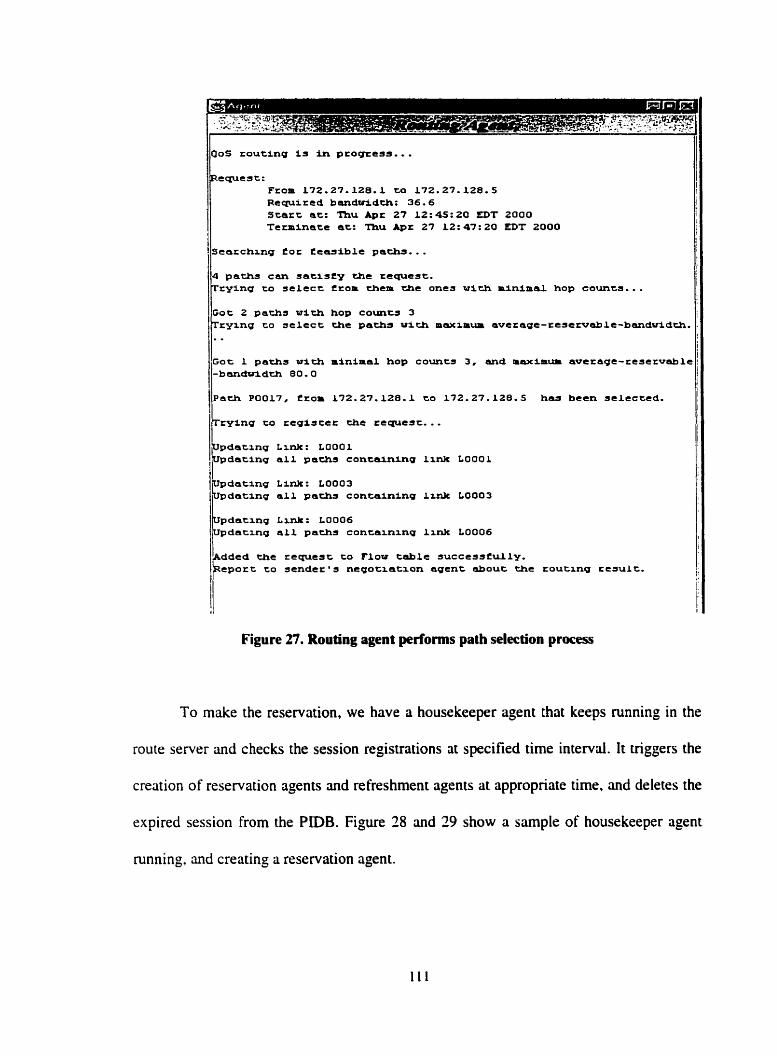
Requcst: From 172.27-128.1 to 172.27.120.5 Requlred b8~1dotidt.h: 36.6 Scarc ac: Thu A p r 27 Lt:4S:20 EDT 2000 Texminate ac: Thu A p r 27 12:47:20 EDT 2000
Scarchang for t e a s i b l e pachs.. . paths can s a t i s f y the requcst. rylng CO select from chen the ones w i c h m i n i m k L hop c o u n c s . . .
Got 2 paths w i t h hop coinits 3 IL rylng CO s e lec t the pachs w i t h m w a m u m avetagt-rcserv~le-b~d~dch. I ;
P0017, from 572.27.128.1 to 132.27.128.5 has becn selected.
rylng CO regiscet chc requcsc.. .
.(. - Goc 1 pachs w i t h minimal hop councs 3 , and m a x i m u m average-rese~vsble
IL pdatzng Lrnk: L O O O l
l pdating al1 pachs containinu Llnk L O O O l
pdating Link: LOO03 dating a l 1 paths contalninq l i nk LU003
pdatlnq L~nk: LOO06 pdatxng al1 pachs contalnxng lxnk LOO06
dded the request Co Flow table s u c c e s s t u i l y . eport to stnder Os negotLatxon agent about the toutang c t s ~ l t .
i
I
i i
Figure 27. Routing agent performs path selection process
To make the reservation, we have a housekeeper agent that keeps running in the
route server and checks the session registrations at specified time interval. It triggers the
creation of reservation agents and refreshment agents at appropriate time. and deletes the
rxpired session from the PIDB. Fi,we 28 and 29 show a sarnple of housekeeper agent
running. and creating a reservation agent.
I -banduidth 80.0 i I'
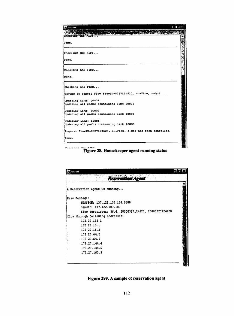
i$dacmg Link: LOO03 1, pdatrng al1 pa- concaxrung lrnk 10003 :l :/Updacmg Lm*: LOO06 !ppdarlng a i l pa- consaxnang L u i L LOO06 I
Il .Rcquest flowID-0327124520, ou-Flou, 0 4 0 s has been eancelled. '1 banc.
1
i L r b r r r r -..a O 7 n P
Figure 28. Housekeeper agent running statu
;A Reservation Agent is naining.. . Il Ipesv ?kssaqe: Il SESSION: 137.122.107.154,8888 11 j Sender: 13?.122.lO7.l89
1' f lov descriptor: 36.6, 20000327124520, 20000327124720 j,f low through f olloiring addresscs: I j 172.27.192.1 I I
! 172.27.16.1 172.27.16.2 172.27.64.2 172.27.64.4 172.27.144.4 172.27.144.5 172.27.160.5
Figure 299. A sarnple of reservation agent
t 12
CHAPTER 6
CONCLUSION AND FUTURE WORK
6.1 Summary
QoS is an important issue in network data transmission, especially for multimedia
applications. More and more such applications require efficient QoS suppon. Based on
the research of different technologies and approaches in this area, we presented in this
thesis a server and agent based architecture to provide QoS services and management.
We use a route server on behalf of individual routers in a network domain to perfonn
QoS management. such as QoS routing, resource management, reservation and
adaptation. for multimedia applications that need QoS suppon. The architecture is
organized in hierarchy. The domain route server (DRS) performs QoS management in the
particular domain. On top of the DRS level, a parent route server (PRS) is in charge of
QoS management cross multiple domains. in addition to the QoS routing and resource
management, The architecture also provides QoS negotiation services to the multimedia
applications to negotiate and agree on proper QoS parameten for data transmission.
For the route server to manage the network resource sufficiently and have an
overall knowledge and command of the resources usage in its domain. we set up a path
information database (PIDB) in each route server to maintain the information of dl the
valid paths that can be potentiaily used to provide certain QoS. PIDB is the base for
resource and session management, and also the source for QoS routing and resource
reservation, etc. We presented the facts that prwf such database can be setup and
maintained efficiently.
The architecture is implemented using the combination of mobile agent and active
network technologies. The various functions of route sever are carried out by various
dedicated agents. Some of these agents perform tasks at application level, such as
negotiation. routing and session management. Some perform network level functions.
such as resource reservation and refreshment, using the idea of active networks. The
architecture is built as an application on a mobile agent platform, SHIP-MAI. The
platform provides us with the necessary agent management facilities and services. such
as. agent and host registration. security, communication and migration. etc.
In the Rrst round of implementation. we considered only the bandwidth parameter
of QoS for point-to-point multimedia service. We have irnplemented the functions of
senderireceiver negotiation and routing; setup the PiDB for a sample network domain:
and implemented the housekeeper to manage the PiDB.
6.2 Future Work and Suggestions
First of the future work is to complete the implementation of other functions of
the architecture. including QoS reservation. adaptation and network performance
detection.
For the reservation phase, we need to implement reservation agent and
refreshment agent, and configure the process of setting reservation States in related
functiond entities of routers and hosts. The implementation of this phase c m refer to the
implementation of RSVP protocol.
In adaptation process, the issue that needs more research is QoS monitoring
mechanism. That is, how often the monitor agent is sent out by the route server to the
designed target points? Where are such points to perform the measurement? Or. the other
way round. we may let the routers to be aware of the existence of the route server, and
report to the route server of any changes and malfunctioning in their interfaces or links.
etc. Then the adaptation c m follow the steps described in the previous chapter.
The network performance detection is another issue deserving more research.
Monitor agent is dedicated to monitoring the active session and detecting if the actual
QoS meets the agreed parameter values. The detection agent, on the other hand. is io
periodicdly collect network link level performance data from the routen and update the
PIDB. We need to develop the working mechanism of detection agent.
Also, we need to add policy control module in router server. The policy control is
perfonned before conducting the routing to decide whether the QoS request is
administrûtively permitted to reserve the resource in certain domain.
Besides the above work which is to complete the designed functionality of the
architecture. we mûke several suggestions as further extension or enhancement.
(1) Include other QoS parameters, such as delay, jitter and loss rate, in the negotiation
and routing. Different application may emphasize on different QoS parameters.
Some require bandwidth guarantee, while some require delay guarantee, and some
may be very critical on jitter rate. Therefore, the critena for path selection should be
different.
(2) tmplement other path selection algorithms to be conducted by the routing agent. The
routing agent should be able to choose the most appropriate algorithm undrr
different network conditions. and for applications with different requirements.
(3) This proposed QoS management architecture cm be extended to be a common
platform with different network functions and provide iniegrated services. such as,
network management. accounting, and security. etc.
References
G. Xie, et al, "SAAM: An htegrated Network Architecture for htegrated Services*', Proc. 6'h IEEEnFIP International Workshop on Qicality of Service, Napa, CA. May 1998.
J. Yu, B. Manning, Y. Rekhter. "Router Server Technical Oventiew", Technical report. January 1998. Online information: http://www.rnen t.edu/overviewWhtml
Q. Ma, P. Steenkiste, "On Path Selection for Traffic with Bandwidth Guarantees", Fifrlz IEEE International Conference on Nenvork Protocols, p 19 1-202, Atlanta, IEEE, October 1997.
Q. Ma, P. Steenkiste, "Ouality-of-Service Routing for Traffic with Performance Guarantees", IFIP Ffih International Worhhop on Qiialiv of Service, p 1 15- 126, NY. May 1997.
Q. Ma. P. Steenkiste, H. Zhang, "Routing High-bandwidth Traffic in Max-min Fair Share Networks", ACM SIGCOMM96. p206-2 17, Stanford, CA. August 1996.
Q. Ma, P. Steenkiste, "Routing Traffic with Quality-of-Service Guarantees in Integrated Services Networks", 8th Internatioricrl Workshop on Nenvork and Opernting Systems Support for Digital Audio and Video (NOSSDAV98). England, EEWACM, July 1998.
F. Sallabi, A. Karmouch, "hrnediate and Advance Resource Reservations Architecture with Quality of Service Routing Agents". Proceedings of 99 bitcniationcil Workshop on Modeling Mitltimedici Information and Systems, p283- 298, Ottawa, Canada, 1999.
S. Berson, R. Lindell, R. Braden, "An Architecture for Advance Reservations in the In terne t". Teclmicul Report. USC Information Sciences Institicte, July 16, 1998.
S. Allongue, R. Impey. E. Horlait, "An Active Network Architecture allowing Mobile Agents construction to improve Quality of Service", Proceedings of 1" Inreniarional Workshop on Mobile Agents Jar Tdecorn?nicnicntion Applications. p83-94. Ottawa, Canada. 1999.
[IO] K. Shin. et nt, "Multimedia-Friendly Server and Communication Design". IEEE Mdrimedin, p84-90, Apnl-June. 1999
[LI] A. Vogel, et al., "Distributed Multimedia Applications and Quality of Service: A Survey", IEEE Multimedia. Vol. 2, No. 2, 1995,
[12] G. Xie, et al, "Efficient Management of Integrated Service Using a Path information Base", Technical report, NPS-CS-98-013, Department of Computer Science, Naval Postgraduote School, May 1998.
[13] G. Stupp. "Application Network-Layer Quality of Service (QoS)", Online document: http://theta.rnath. t a u . a ~ . i l / O 0 S r m i / r e ~ p o ~ . h t m 1 .
[14] S. Floyd, V. Jacobson. "Link-sharing and Resource Management Models for Packet Networks". IEEUACM Transactions on Nenvorking. 3(4): p365-386. August 1995.
[15] E. Takahahi, P. Steenkiste, "A Programming Interface for Network Resource Management." Second lEEE Conference on Open Architectures and Network Programrning (OPENARCH'99). New York. M a c h 1999.
[16] A. Hdid, G. Bochmann, "An approach to Quality of Service Management in Distributed Multimedia Application: Design and an hplementation", Multimedia Tools and Applications Journal, p 167- 19 1. 1998
[ 171 P. Dini, A. Hafid. '"ïowards Autornatic Trading of QoS Parameters in Multimedia Distributed Applications", Procerdings of IEEEi7FIP ICODP/?CDP Corference, Toronto, Canada, 1997
[18] "Quality of Service (QoS) Networking", htemetworking Technologyies Handbook. ?""dition. Cisco Press Pubilications. Online documentation ai: h t tp://www.cisco.com/cpress/cc/tdcpress/fund/i t h 2 n .
[19] A. Kmouch , V. Pham, "A Mobile Agent-based Architecture in A Networking Environment". Technical Report, Multimedia Information and Mobile Agent Research Laboratory. SITE, University of Ottawa. 1997. 1999.
[20] V. Jayararnan. V. Pham. A. Kamiouch, "Secure and Efficient Communication In frastnic ture for A Mobile Ageni S ystem", Tec hnical Report. Mu1 timedia Information and Mobile Agent Research Laboratory, SITE. University of Ottawa, 1999.
[,II "Preside Quality of Service". Norte1 Networks product brief, http://w ww .nortelnetworks.com/servup
[X] R. Braden, et al, RFC 2205, "Resource Reservation Protocol (RSVP) - Version 1 Functional specification", ftp://ft~.ietf.org/intemet-drafts-ietf-v-c- 16 .p~ .
[23] E. Crawley, et al, W C 2386, "A Framework for QoS-based Routing in the Internet", http://www.cis.ohio-state.edu/htbin/rfc/rfc2386.ht~
[24] S. Berson. S. Vincent, "Aggregation of Lntemet Integrated Services State", [ntemet Draft. USC/ISI, August 1998
[25] V. Pham. A. Karmouch. "Mobile Software Agents: An Overview". IEEE Cornmitnication Magazines, p26-37, July 1998.
1261 H. Nwma, "Software Agents: An Overview", Knowledgr Engineering Review. Vol. 1 1. No. 3. pp. 205-244, OctoberMovember 1996
[27] 0. Huber, "Multimedia Services based on Agents", IBC Intelligent Agents Con ference, London, 1997.
[28] J. Dale. D. DeRoure, "A Mobile Agent Architecture for Distributed Information Management". Proceedings of the International Workîhop on the Virtidal Mdticompu ter, March 1997.
[29] G. Goldszmidt, Y. Yemini. "Delegated Agents for Network Management". IEEE Cottimirniccition Magn;ines. p66-70. March 1998.
(301 S. Franklin, A. Graesser. "1s it an Agent. or just a Program?--A Taxonorny for Autonornous Agents", Proceeding of the 3d International Workshop on Agent Theories. Architectures. and languages.
[3 11 C. Harrison. D. Chess, A. Kershenbaum, "Mobile Agent: Are They a Good Idea?", ISM Research Division, Online documentation: http://ww~v.research.ibm.com/massdist/m.ps.
[32] A. Bieszczad. B. Paguret, T. White, "Mobile Agents for Network Management". IEEE Comniiinicntion Sirrveys, Founh Quarter 1998, Vol. 1 No. 1. p2-9.
[33] Bill Venners. "Solve real problems with aglets. a type of mobile agent", Java World, May issue 1997.
] D. Tennenhouse et ni, "A Survey of Active Network Research. IEEE Cotntnirniccztions Magazine. Vol. 35. No. L, pp 80-86, Jan 97.
] U. Legedzn. D. Wetherall, I. Guttag. "hproving the Performance of Distributed Applications Using Active Networks", IEEE INFOCOM'98, San Francisco. Apnl 98.
[36] 0. Huber, L. Toutain, "Mobile Agents in Active Networks", ECOOP'97 Workshop Mobile Object Systems, lyv&kyli-i, Finland, 9 - 13 June 1997.
[37] K. Psounis, "Active Network: Applications. Security. Safety, and Architectures". IEEE Cornmitnication Siirveys, p2- 16, First Quarter 99.
[38] J. Smith, et al, "Activating Networks: A Progress Report", IEEE Cornputer, p32-41. April 1999.
[39] K. Calvert, "Directions in Active Networks". lEEE Commiinicatiori Magazines, p72-78. October 1998.
[40] D. Tennenhouse et al, "Towards an Active Network Archticture", Cornputer Communication Review, Vol. 26, No. 2. April 1996.
[41] B. Furht. "Multimedia Systems: An Overview", IEEE Multimedia, p47-59, spring, 1994.

![15-744: Computer Networking L-18 QOS - IntServ. QOS & IntServ QOS IntServ Architecture Assigned reading [She95] Fundamental Design Issues for the Future](https://img.pdfslide.us/doc/110x75/56649cb95503460f9497f8fe/15-744-computer-networking-l-18-qos-intserv-qos-intserv-qos-intserv-architecture.jpg)