Embed Size (px)
Citation preview
NOTE: This document identifier and heading has been changed
on this page to reflect that this is a performance specification,
There are no other changes to this document The document
identifier on subsequent pages has not been changed, but will be
changed the next time this document is revised.
NON-MEASUREMENT
SENSITIVE
MIL-PRF-28000A
10 February 1992
SUPERSEDINGMIL-D-2800022 December 1987
PERFORMANCE SPECIFICATION
DIGITAL REPRESENTATION FOR COMMUNICATION OF PRODUCT DATA:IGES APPLICATION SUBSETS AND ICES APPLICATION PROTOCOLS
Thii specificationis approved for use by a!] Departments and Agencies of the Departmentof Defense.
L SCOPE
1.1. -. This specification identifies the requirements to be met when product definition data is delivered inthe digital format of the Initial Graphics Exchange Specification (IGES) as specified by its AmericanSociety ofMechanicalEngineersstandard, ASME Y14.26M. Dkrete subsets andkr applicationprotocols of the ASMEY14.26Mentities are identified by class according to the application for which the digital data was prepared.
1.2. Classification. The digital representation of product definition data shall be one or more of the followingclasses as specifiedby the contract or other form of agreement:
class I - Technical IIlustmtion Subsetclass 11 - Engineering Drawing Subsetclass 111 - Ekctrical/Electronic Applications Subsetclass Iv - Geometty for NC Manufacturing SubsetChss v - 3D Piping Application Rued
Additional classes are expected to be added in future versions of this specificationas soon as the technicalworkcodifies their requirementsand validates fitness for use.
I 1“Beneficial comments (recommcndatio~ additions, deletions) and any pettinutt data which may beof use in improving this document should be addressed to: A’Hlk CALS Digits! Standards Offke,DISA, Center for Standards, Code lIEO/JEBE13, 10701 Parkridge Blvd, Reston, VA 22091-4398,by using the self-addressed Standardization Document Improvement Proposal (IID Fotm 1426)appearing at the end of this document or by letter.
AMSC NtA AREA IPSCDISTRIBUTIONSTATEMENT A, Approved for public release; distribution is unlimited.
Downloaded from http://www.everyspec.com

MIL-L)-28000A
2. Applicable documents
2.1. Govemnumtdocuments.
-
2.1.1. Soecikat.ions and standds. The following qxzifkations and standards form a part of this specification10the extentspecifti herein. Unless otherwise sjwifwxl, the issues of these documentsam those listed in theissueof the Depmment of Defense Index of S@fkations and Standards (DODISS)and supplement thereto,cited in the solicitation.(See 62)
Mititary specification
ML-T-3 1000- Technical Data packag~ General Specificationfor
Federal informatim prwcsshig standard
FfPS PUB 79 - Magnetic Tape IAmls and Fik Structure fw InformationInterchange
(Copies of the Federal Information and l%ocesi~ Scmdards (FIPS) are availabk toDepWmemof Defease activitiu htnthesmdmbtim DocumentsOder Ilerka Building4D, 7(XIRobbins Aveme, Phiilphia PA 19111-5094. Others must request copies of FE%from the National Tcchnicd Infamation SeMce, 5285 Port Royal Road, Springfml&VA22161-2171.)
Mititary standards
DOD-STD-1(XI- Engineering ~wing Pmcri@s
MILS’ID184(I - Automated Interchangeof Tcchnkal Jnfomtatkm
(Copies of the@zcnccdmilitaryspecifm@xtsandsa ndmdsmeava ilabkfzumtiStdadidm DocumentsOrder Desk Building 4D, 700 Robbins Avenue, PhiIadelphi&PA19111-s094.)
2.1.2 Other ROvWmnmt documents. The fdknving othexGovernmentckcuments fcxma part of thisSpecifiito thecxtentspedfkd ha’ein. Urdessotkrwme“ $pccM4theisaues of these documalts8rethosecited in the solicitation.
Natkmal instMutcof standards and technology
IGES Technkal Illustdons Application Guide. issue dmtehJ]y 19.1990, MSTIR 4379
IGES 5.0 Recommended14wices Chide - M8y 1991. NISTKR4600
lGES Ekctrical Application Guide, March 1987 (Draft)
3D Piping IGES ApplicationPro[wol, Vemion 1.1, March 1992, MSTIR 4797
Downloaded from http://www.everyspec.com

MIL-D-28000A
(Application for copies of the above documents shatl be addressed to the National Technical
Information Semicc, 5285 Port Royal Road, Springfleid, VA 22161.)
IGES V5.Oinitial Graphics Exchange Speeifieation, Vetaion 5.0, September 1990,NISTTR4412
(Application for copies of the above document shall be addressed to: National ComputerGraphics Association, 2722 Merrike Drive, Suite 200, Fairfax VA,22Q31, A’f71W fFGAdministrator)
2.2. Other nblications. ‘l%efollowing documents form a pan of this specificationto the extent specifiedherein. Unlessotherwise specified, the issues of the documents which are DGD adopted are those listed in theissue of the DGDISS specifkxl in the ~imtion. unl~ othemvisespecified, the issues of documeats not Medin the DGDISSam the issues of the documents cited in tk. solicitation. (See 6.2)
ASME Y14.26M Digital R_tation fbr Communication of Fmduet Definition Data 1989Edition
(Applkation for copies Shall k ddrcssd to: The AmezieanSIX* of Mechanieai Engineers,345 East 47th S- New Y- N.Y. 1(X)17).
(Nongovmment standmk and other publications are nonntdly available htn the oqpmizationswhich prepare w wttieh distriite the documents. Ths docunmts also may be available in mthrough libraries or other informational serviees.)
2.3. Grda of meed enee. In the event of a eonfliet between the text of this speeilieationand the mferemzscited herein, the text of this “spedbim shall take precedence. Nothing in this specifkxtion, however, shallsupersedeapplieabk laws and reguhions unless a specific exemption has been obtained
.3
Downloaded from http://www.everyspec.com
MIL-1)-28000A
3. Requirements
3.1. General rw uiremcnts. Ail digital product data fdes cotnplying with this spccifwationshall conform to theidentifkd subset or applicadon protocol class. The specif~ subset or appkation protocol class shall beidentifiedby entry in the start salon of the fde.
3.1.1. Restrictive nature of subsets. A data ffle conforming to this specificationshall utilize only those sp%ificentities identified in the refennccd subset or application protocol class for representingthe product definition.Additional “volunteer” entity types may be pre.scrtt as long as the= entity types are:
a. Valid ASME Y14.26Mentities.
b. Not necessary to the product data representation.
c. solely f(x the purpcse of rcgcnaatin g the same dcvdopmmt environmem when the fk istransfemd back to the same computer aided design (CAD)system which originally genemt.edthe f~andntay &ignored byotber CADsystems
These vohmteezentities do not include gcomeuy. Rather, they typically include IGES-definedpmpe.rfies,user-dew prqxmks, and associativem color definition entitks. A peat—prommr(see 6.6.13) is not required10tmnstate these “volunted entity types rnto the data base of its CADCAM system, but is rcquird to continueprocessingthe remairtdexof the data fk.
3.1.2. Limits on mramctex data A data fik confcmningto W specificationshall not contain solar values ofpm* OUtS* the ranges specifti by the ickntiftcd subset or applkation proud ciass.
3.1.3. PWical file structure AHdigital product data fh complying with this specification shall be written inthe ASCII form specified by ASME Y1426M. The b- fcmnShd not be used
3.1.4. PhYakal media for CklivcsyoUnkss Otkrwisc specified in the solicitationau data fdes complyingwiththis spedkntion shall be dclivescdon 9-rr8ck_ tape as qecifkd in MIL-STD-M40. Tape format shalIk * ~ with HI% ~ 79 with ~ vol~e MS W fik MIs -plying with Level 3 or Level 4of the stdard. Acceptable tape (knshks am 1600 and ~ al Oldy.
3.2. Suecific rut uirements. The following subsections defuw I& requirementsfor each defined subset orapplicationprotocol class, A conformingdata 61e shall use the spxifkd ASME Y14.26M entity types and formnhrs fff rcpmwuation of data in the idcntifii Classsubaej. All mf~ to entity typeq form numbm,and data fields arc rcfClwlCesto ASME Y14.26M for classes I-IV. Class V, the 3D Piping Application ProKzol,uses lGES Vemion 5.1 ati~ ace the ‘3D Piping IGES ApplicationProtocol”document for details.
3.2.1. Class I Sttb=t - technical Wmaticms. The Technkal Ilhstradon subsa of ASME Y14.26M addmssmentities that support the exchangeof figures and illustrations nmnally found in a technical publicatiat. In hisapplication,emphasis is on visual clarity of figures ml illustrations designed for human inwrprctation. ‘1’IwlGES Technical Illustrations ApplicationGuide provides additional guidanceon this usage of IGES.
Downloaded from http://www.everyspec.com
MIL-D-2$000A
3.2,1.1. Information raIuimmcntsand data functionality.Two dimensionalgeometry and text annotation form
the majority of data items although some non-geometricinformationis required as well. Informationrequirements fm this applicationsubset include (but arc not limited to):
a. Simple two dimensional gcomeuy in the form of lines, circutar arcs, conic arcs, and splinecurves.
b. Non-geomerricattributes of line weight and line fOnL
c. Text annotation.
d. IXta rclazimahips, including the concept of subfigures.
3.2.12. ASME Y14.26M cmtitvsuti stxc ific@on. Tabk 1 lists the entities of thii subacL, Only ASMEY1426M entities WhiCharc cn~ in this table shall be used fm rqxeaemtingtcchnicd publicatkmillusuatkn productddinithdata ~#~M~Y14XM~~myk_thtif*Sdescali%edby 3.1.1. Additional q uiremcnts wc placed on the Global SCCtionof a fde, and certain field valueresUktionsareakopkcdon tkrangeof parametervalucs intmthtbc dimctozyemtry(DE) andthepammcWrdata (H)) sections of a valid ASME Y14.26M fik.
32.13. File cmmwtion.
3.2.13.1. Start aecticm. The following infonnatkm shall be plti in the Start Section of the fde
a. Statemm of cmfamancc IOthis application SUW the applkabk revision kvd of thise-titi m-~edtiti~mtmti~mm(wtiofblatest mision if no amendment has been issd).
b. Illusmion number or idcmtif~.
5
Downloaded from http://www.everyspec.com

MIL-D.Z8000A
TABLE I. - ASMEY1426M entiv content of technical ilktration subset
When the form alum in Tabk I is blank for an entity which has multiple form numbers,all formsof thatentity are included in the subseL
ENT FI oT R NOTESYM ENTITY NAME DE PD
--- .—~. .—--—— —— .-—.-—- .-.---- ——- -.-..— ——● 0 Null
]m CkIllarti 3 2102 Composite curve 1 4
104 Culic Arc 3 2
104 1 conic Arc 3 2104 2 conic Arc 32104 3 conic Arc 3 2106 11 m Lii string 1 15106 63 simple closed Pianar curve 1110 Line 1 2112 I%rametricSpline curve 1 25124 0 TransformationMatrix 6 7126 Rational B-Spline Cum 1 8212 General Note 10 2,11230 Sectiald Azca 1 2308 Subfigurc &fhitiOll 644(M DI?lwing 9406 15 Name 16406 16 Dmving size Property 12406 17 Drawing UNIS
* 406 18 IntcrcharacterSpacing 1408 Subfigure Instance 32410 view 6 13412 Rcct hlly Sub Instance 3 2,14414 Circ Array Sub lnstanca 3 2,14
—
* Denotes an ASME Y14.26MAppendixJ, Untested Entities, capability
Downloaded from http://www.everyspec.com

MIL-D-28000A
NOTES FOR TA5LE I:
1.
2.
3.
4.
5.
6.
7.
8.
9.
10.
● 11.
12
13.
DE Field 4, Line Font pattern, shall be 1,2, 3,4, or 5DE Field 5, Level, shall be ODE Field 6, View PcWer, shall be ODE Field 7, TransformationMatrix Pointer, shall be ODE Field 8, IAbe!Dwlay Winter, shall be O.
PD Index VaIues for Z coordinates shall be 0.0.
DE Field 4, Line Font Pattern, shall be 1,2,3,4, or 5DE Field 5, Leve~shall be ODE Field 6, View I%intcr,shall be ODE Field 8, Lakl Display Winter, shall be O.
PD Index values shall @t only to otha entity types within this sub-
PD hdCX 3, Pianar, dd k 2
DE Field 7, TransformationMatrix, shall be O.
TransWon and rotation arc restricted to XY plane. PD lndicxs R13, R23, R31, R32 and T3shall be 0.0, and R33 shall be 1.0 or -1.0
PD Index 3, PROP1 (Plan@, shall be 1, 2S( shall be 0.0, XNORM and YNORM shall be 0.0ZNORM shall be 1.0 (x -1.0.
PD hKkX 1, Numbcrof view pointers, sha!l be 1PD Index 5, Numb of ammtiOnmasilallbeoPDlndcx&Number ofasamiaWty pointenKshaUbe OPDIndex7, Number ofpqcrty poin~, QIallbe 1,2 W3PD Index 8-10, a DE pointcxto a Ropcrty (406, Form 16) is required, a DE pointw to a~(~-l$k@@,aDE@-ma~(W,ti 17)iao@onaL
DE Ficid 5. Level, shalt be ODE FAd6, View~, abaUbe0DE Field 7, ~ “ Matrix Wintef, shaUbe ODE field 8, W -y S%inteJ,shall be O
PDIndcx 5, FuKCbmwmoG“ “ shall IE 1,1001, IOQ m 1003.IfapOhrmapopaty cntity(406, Form18)isuscd toamuolintmharxw spacing, thenany ASME Y14.26M ftmt value maybe used.
DE Field 5, Level, shall be O.
PD Index 2, ScaJe,shall be 1.0.PD Indices 3-8 shall be O.
● Denotes an ASME Y14.26MAppendizJ, Untested Entities, capability
7
Downloaded from http://www.everyspec.com

MIL-D-28000A
14. W Index Values shall not poim to cmity type 412, entiIy type 414, or an entity 308 which@tts to a 412 or 414, and shall only point to other entity types within this subsc~
15. N1 (the number of Points, PD Inckx 2) shall be 3 or more.
16, The Name Proptly entity shall take precedence over a name in DE field 18, Entity Label, forany entity which has a name prwpaty.
3.2.1.3.2.Global section. Fklds in the global section shatl be restricted to certain ranges and shali not bedefauhcd except as noted below for paramcuzs }, 2, 12,20, and 24.
Field123-67-111213141516-192021222324
Value Rquti* N Default to ,.* N Default to ;
YNN Default to F~ld 3
1.0 Y13,4-11 Y
NYN Dcfatdt to Field 1NN
4-6 Y0-7 N Default to zelo
32.133. D“utcurven trv section. See Notes for Tabk I for restrictionspkid on the parameters in thedirectoryentry scdon.
32.13.4. hameter data section. see Notes for Table] fm teSbktiOltS @Kd on the ~ in ~
pmmetcr data Seuion.
Sevaal entity Smcttms inthissuhsct havcbeutincluckdto kcepthc fdesizc toaccqxablekwk. l%-the use of subfigurcs greatly rcdtmxsfile size whore ilhsrationcktaiisarefepacd. Similsriy, the generalnoteentity isacompact tnahodofqmendng tcxtannotadon ascompafcd withthcsllukitq! Ofcachch=actattsmlineandarcgcomeuy. Howcm, thcm~inmnces whcsc ● systun lacks the tuphistiation of suMP entitytmnstructsoritisdcsi mdtostrokcthete.xtfora spdaiappcamcen otolhemisea aainabk. Useof ASMEY14.26Mcmstructs, liitiintemtitcr ~ittg propcxtyforpqordod tcxgiscmtxnw@to mlutxfiklengths. (See 6.3.) Lima, aplines, linear curves, arcs, and coNc am shall not have a zero arc klgth (e.g. zero
length mu’ves).
3.2.1.5, Data ~Ctm3Cy rcuuircmcnts. All data transformations shall maintain an accumcy of at least 0.001 unitson all parametricand coordinate values and ail mcastttabk dimensions.
8
Downloaded from http://www.everyspec.com
M[L-D-28000A
3.2.1.6. User conventions and data orKaniza;ion. A minimum complexity &awing/view entity combination,
along with its drawing si~ propemy,shall be used to assure an illustratkm being created on all receivingsystems.
3.2.2. Class 11subset - engin~rin~ drawin~s, This engineering drawing subset of ASME Y14.26M shall beused to eneode product data being acquired in accordance with ML-T-31000 for delivery in digital form. Thedata exchangeshall preserve the requirementsof styk and euntem as set forth by DOD-STD-l(XIandMIL-T-31000. Exchange emphasis is m completeness, visual quivalency for human interpretation,andfunctionalityof the received drawing.
3.2.2.1. Information w uirements and data functionality. Currently,engineering drawings form the mainstay ofproduct definitionand fmrn the aeeepmdmedium for viewing computer generated data. Geunetry and textannotation form the majcrity of data items. Extensive use is made of dimmsions, sectionedareas, text notes,
and featurecontrol symbols. Non-gmmetric information in the fam of edor, line weigh~line fong and level is
neded as well. FmalIy, relationships among the data help to structure the large quantities of data. lnfcmnationrequirements for this application subset include (but are not limited 10~
a. Simple geomeay in the form of points, lines, cimukr ares, conic ares, and spline CWS.
b. Non-geometricattributes of color, line weigh~ and line font.
c. Data relationships, including the eoneept of subfigums.
d. Data organkmtkm methods such as level
e. Pan name, drawing number, formal idenMkation, and drawing revision.
f. Annotation rqmwttted by rhe corresponding ASME Y14.26M entity typethusretaining itsintcnckd functionality.
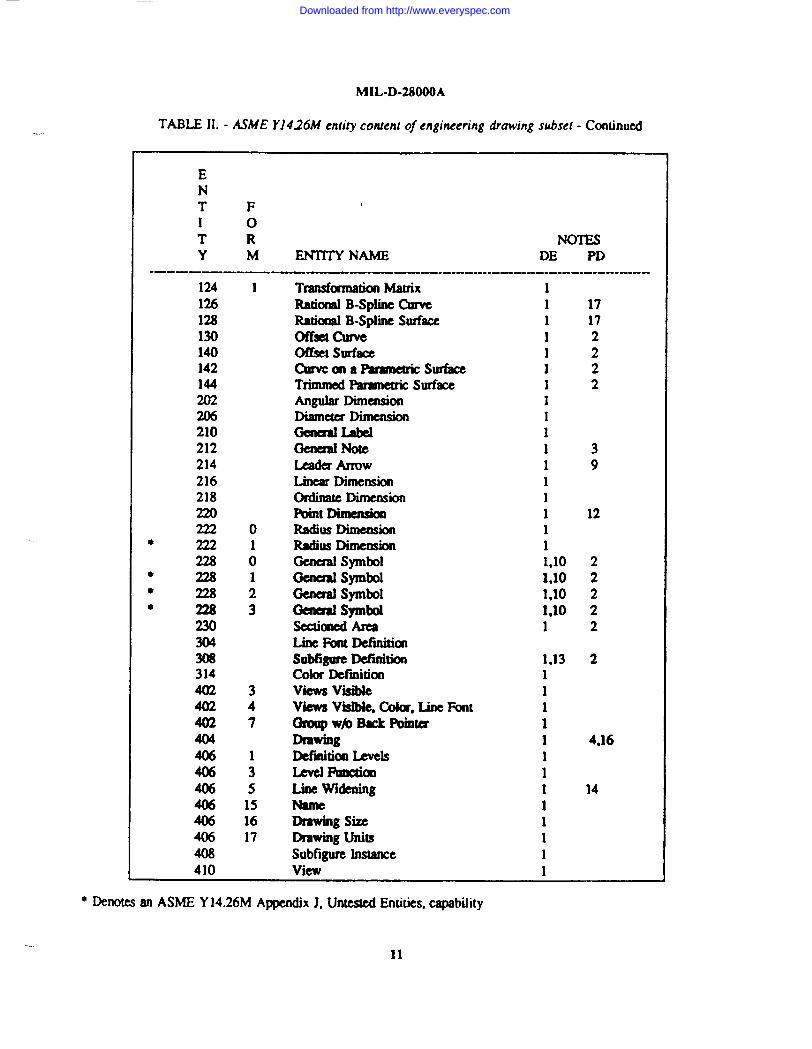
32.22. ASME Y1426M entity subsx stxc ifieatiat. Table II lists tk entities of this subseL Only ASMEY14.26M entities which are enumerated in this table shall be used fm rqxeaenting engineuing drawing product
definition data. other valid ASME Y14.26M entity types maybe psemit in the file as deseribedby 3.1.1.Additional requirementsare placed on the global seetion of a fde, and certain field value restrictions are placedon the range of parameter values in troth the dirtztory enrg(DE) and the parameterdata(PD) sections of a validASME Y14.26Mfde.
9
Downloaded from http://www.everyspec.com

MIL-D-28WOA
TABLE H. - ASME Y1426M entity conknl of engineering drawing subset
When the form column in Table 11 is blank for an cnti[y which has multiple form numbers, all farms of thatentity arc irwludcd in the sub=
ENT FI oT R NOTESY M ENTITY NAME DE PD
.. ..— ———● 0
100102104104104104106106106lM1061061061061(M106106
106
1061061(M108110112114
116118120
12
3
11
12
202131323334353637
38
406301
Nullcircular Arccomposite curveConkkcCcmickcconk Amconic Arc2D LH suing3D Linear SuingCentdne -nlrOUghr%iirsCaltcrlinc T1’mlghCimk centersSaX.km(parallel line segments)SeCtion(parallel line Se&inpairs)section (aknathg solid& dash scg.)
scuion@ralkl lincsinquad.)Section (triples of pm7dkl lines)Sectian@lmlkl aclsofdl@sq3.)Saaial (two pUpcndkuisr sets ofpmllel lines)section (2papcndicullx setsof P@-M lines-@cipal solid& 2nd dashed)Wimcss Litwsimple Ckxed Planar curveUnbounded planeBounded PlaneLmPar8fnaric Splint Clln’ePammcbic Spline SurfacePoiitRuled !$urkeSurface of Revolution
11111111111111111
1
1111111111
2555566
11
715
8,178,17
22
-
● Denotes an ASME Y14.26M Appendix J, Untested Entities, capability
10
Downloaded from http://www.everyspec.com
-.
MIL-D-28000A
TABLE II. - ASME I’J426M entity confent of engineering &owing subsel - Conlhmd
ENT FI oT R NOTESY M ENTITY NAME DE PD
.—. ——-. —-—. -———. ———--. -.--. -.-— —------------- —-124 1 TransformationMZltfiX 1126 Rational B-Splint Ctnvc 1 17123 Ratiannl B-Splint Surfaw 1 17130 Offscl curve 1 2140 Ofkct Surfatz 1 2142 CmWcma%amctnc “ surface 1 2144 Trimmed F%ramuricSurface 1 2202 hgulaf Dimalsion 1206 DiaInc& Dimcn&m 1210 GcnaaILabcl 1212 Gend Note 1 3214 Lcada Alrow 1 9216 Linear Dimnsion 1218 ordinate Dimension 1220 Point Dimensh 1 122220 Radius Dimuision 1
* 2221 Radius Dimension 122s0 Ocnual symbol 1,10 2
● 2281 Oalml symbol 1,10 2● 2282 GeJKxalsymbol 1,10 2● 22s3 (3au81 Symbol 1,10 2
230 Scctialtd Area 1 2304 Line I%nt Wfinition308 SObtigurcDefinition 1,13 2314 Color Dctinition 14023 views visible 14024 views Visiblq Color, Unc Font 14027 Orotlpwb Back Pbintcx 1404 Drawing 1 4,16406 Dcfdticm Levels 1406: Level Futxzial 14065 Line Widening 1 14W5 15 Name 1406 16 D!awing size 1406 17 Drawing Units 1408 Subfigurc Instance 1410 View 1
* Denotesan ASME Y14.26M Appendix J, Untested Entities, capabdity
11
Downloaded from http://www.everyspec.com
}IIL-D-28000A
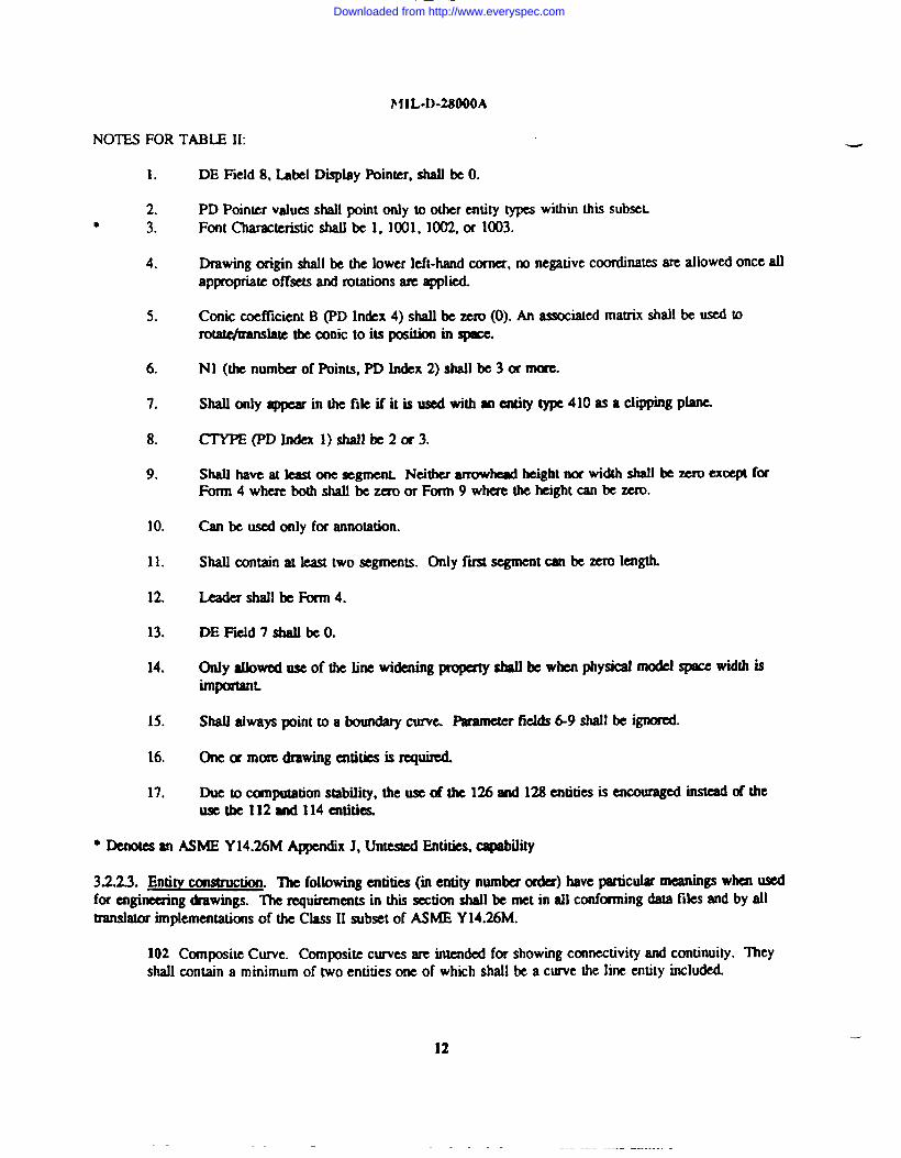
NOTES FOR TABLE 11:
1.
2.● 3.
4.
5.
6.
7.
8.
9.
10.
11.
12.
13.
14.
15.
16.
17.
DE Field 8, Label Dqlay Pohtter, shall be O.
PD Pointer values shall point only to other entity types within this subseLFont Chmmeristic shall be 1, 1001, 1002, or 1003.
Drawing origin shall be the lower left-hand corner, no negativecoordinate are allowedonce allappropriate offstls and rotations arc applied.
Conic coefficient B (TD Index 4) shall be mm (0). An associatedmatrix shall be used torota@ranslate the conic to its position in ~
NI (the numbczof F%ints,PD In&x 2) shall be 3 or more.
SWmly~in tifiktiitk ~tiWm~V ~410mad~mgpW
CTYPE(PD lndexl) shall be20r3.
Shatl tUVCat least one acgtncm Neither arrowkad height nor width shatl be m execpt fcwForm4where bcxhshaU bezcroor Form 9whc.re theheightanbezcro.
Can be d only for annotation.
Shall contain at kast two segments, Only f- segment can be xcro length.
[email protected] be Form 4.
DE Fk.ld 7 shall be O.
~yti~wofti ti~titing~~kwb~ydd modclspacewidthisimportanL
Shall always point to a hunday cume. Paametcr fickis 69 shall be igncxmd.
One m more drawing entities is required
Due to cunpuuttion stabiiity, the uSCof the 126 and 128 entities is eneoumgcdinstead of theuae the 112 and l14attitic&
● Denotes an ASME Y14.26M A-x J, Untested Entities, capability
3.2.23. Entity wnarwbn The following entities (in entity number order) have paticular meanings when usedfor cngineuing tiwings. k rquircnHMs in this wtion sJMIIbe met in d] conformingdaMfiks ~d by d&WtShtOrhphCU.iOllS of the Class II subset of ASME Y14.26M.
102 Composite Curie. Composite ctnes are intended for showingconnectivityand continuity. ~eyshall mttain a minimum of two entities one of which shall be a curve the line entity included.
-
12
Downloaded from http://www.everyspec.com

MIL-D-28000A
124 Transformation Matrix. Definingmatrices am used to position an entity into model space from itsdefinition ~. When entities share the same plane of definition, they shall usc the sametransformation matrix to avoid multiple identical matrbs Wing included in the fik. If an entitycontains translation information in its PD section, a aansformadon matrix shall not be used to translatethe entity.
202 Angular Dimension. This cmtityshsll have two 1- and a vertex point. The Z dkplacement ofthe vertex point can be attained from any of the subordinates.
206 Diameter Dimension. This entity shall specify its arc centex(may not be defaulted). The Zdisplacementof the am center can be obtained h the subordinates. The arc center shall be valid.multiple leadexsoccur, the fmt segment of each leader shall be wllinear and opposite in direction.
212 General Note. -~mfmafat ~mmbtinxof titti~rntinote. M~~tigk ~tihtinm&d Mmnt X~sW&mrnim* Fam
If
numbers plusposirion informationon eachstring ahrdlbeused. TEeWtaticmAnglefie2dsha llcontainthe string M@e. Tra!tsfimnadonmatices aid nu M used fm Sting angks. Null strings arc dOWCd
andmaybe usedtopattczn anoteinmoneofthe standmdf~
216 Linear Dimemkm. WhezIthae= twowitness lines, theyshall beparalleI meachother.2l8Ordimte Dhensim. Thisentity shatlnot beusalin pimeofthc gwmal label. ‘Ilw Iclulexticontain only one segment.
222 Radius Dimension. This entity shall specify its arc center (may not be defaulted). Z dispkxxncntof thearcccntcr can beatminedhotn anyofitssubwdhtes Arc ccmershallbevaiid. Ifmultipkkadessoccur.thefmt scgmentofcach shall becoUinear. Iftwokdemrm@ oncandosdy~sha.ubeof Form4.
22S Ckne.mlSymbol., lldsemity~betifor~mtion. Flags inthesubcxdinate entities (even~)slmubeset manmadon. '!ldsesuitys hsllnotbea aedinplacco fa9uMigumcwgrmp. AllSubordinateeatitks totbcgesled symbol tmtity ShaIlbecopl’anar.
230 Sectioned ha.meiltit yisusedto$xovideforarea fk mnormal dktlmce belwecnlinesiscmstarlt andahalllldbezezo. Wider spaces betwealines mtobemsidemd blank lines withregard tonormal dimnces. Boundarycurve and islands mecloaed andntx~lf- intmedng. Islandintaiors arcmutually disjoint. Island9Iieinthe intczicxof the bmmdarycumc. Bomxkrycurvcandislands eanbclogiadiy depmdem anddonot needtobe marked asammtation iftheyarenot
.
404 Drawing. m drawing entity defines the basic engineaing drawing format for each Shea. onetig~~tilti tihfifm~~m ml~ti~, ofm~~ng~tig.Anexampkof acolkuion ofsktswcxdd beseveral Bsizcshects pkedinan Hsiae@ne&rtgdrawing, All entities pointed to by the drawing entity shall be physically kpendmt and shall be flaggedas annotation.
406 Form 5 Line Widening. The only ailowed use of the line widening property is the case whenphysical mcxlelspace width is important. lt shall not be used to indicateplotter width or line weight.
13
Downloaded from http://www.everyspec.com
MIL-D-21U)OOA
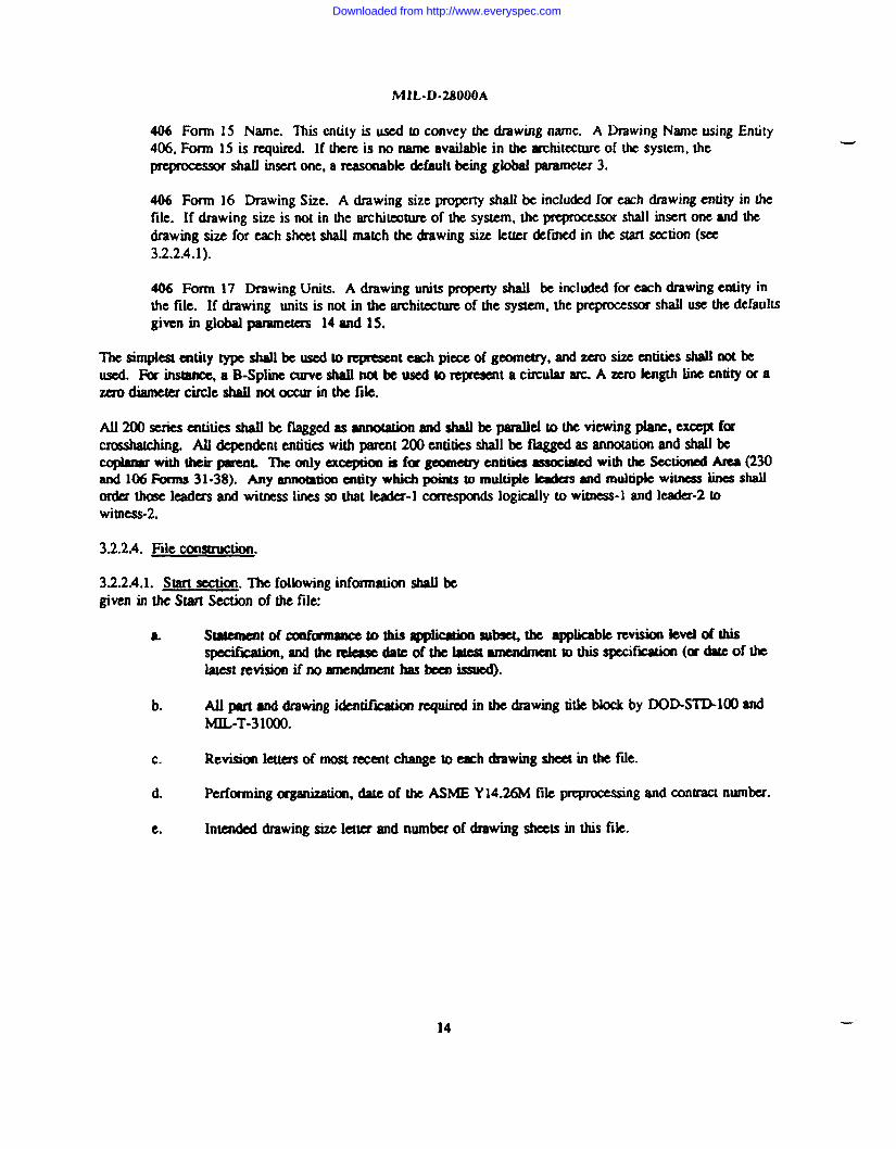
406 Form 15 Name. 7Ms enthy is used m convey the drawing name. A Drawing Name using Entity
406, Form 15 is m@rrxL If there is no name available in the architecture of the system, the
pqmxasw shall insert one, a reasonabk ckfauk being global parameter 3.
406 Form 16 DrawingSize. A drawing size propertyshall be included for -h &awing entity in thefile. If drawing size is not in the architmture of tk system, the pqmcesor shall insert one and thedrawing size for =h sheet shall match the drawing six ktter defined in the starl section (see3.2.2.4.1).
406 Form 17 Drawing UNts. A drawing units property shall be included for awh drawing entity in
the file. If drawing units is not in the architectureof the system, the preprocessorshall use the defaultsgiwm in global parameters 14and 15.
The aimpiestcmtitytype shall be used to mprcsent -h piece of geometry, and zxo size entities shall not beused. For insmnec,aB-Spline euxveshall not beuacdto mprcwmta circular arc. Azerokngth Sineentity orazaodiarnetcrcirclcahaunotoccurin *file.
A11200serics entities shaIlbe flirggtXlasanno@on and shall be pamlkl to the viewing plane, excqn forcmashdhg. All depettht entities with pareat 200 entities shall be flaggedas annotationand shall be_titi~L ~mly=*m kfwg~ati*xW wititi*tih(2Wand 106 Forms 31.38). Any annotationatity which points to muhipk kadcss and muhipk witness lines shallOr&I those leaders and witness lines so that leader-l uxrespmds logically to witness-l and kader-2 towimess-2.
3.2.2.4. File eonsmxxion.
3.2.2.4.1. Start section. The followinginformation shall begiven in the Start Salon of the file
6 s t8tcmmt of C’mfmnmlectothiaa@btirmsubsr%the applieabk revision ievelofthiaspccifrlcation,andthercleasc datcofthelalcat nmcndmmt to this Specif-on (or date of thelatest revision if no amcnhent haskissucd).
b. All part and drawing i&ntif_ required in the &awing Me block by DOD-STD-lCMIandMIL-T-31OOO.
c. Revision kttcrs of most reecnt change to each drawing shca in the fde.
d. Performing organisaticm,date of the ASME Y14.26M fik pqmcessing and contract number.
e. Intended drawingsize letter and number of drawing sheets in this fik.
14
Downloaded from http://www.everyspec.com

Data organization method
Level1
201202
MIL-D-2SOOOA
with contents of each level, for example
Dcsuiptioflmodel entitiesdimension
f cmshatching
32.2.4.2. Global section. Fields in the giobal section shall be mtrkted to cextainranges and shall not bedefaulted except as noted below for parameters 1,2, 12,20, and 24.
Fkld123-1112131415-192Q212223u
value Required* N Defmdtto ,.* N Dcfatdl to;
YN Default to Fdd 3
1.0 Y1-11 Y
YN Dcfindt to Fiild 1YY
4-6 Y07 N Default to zero
3.2.2.43. D- [email protected] rcarric$kxtsp~onthepmmetas indtc~~a~ti:h~,tif-g~b~tibxnd shaUbeqqmrtedforaUentities as mqlired by ASME Y1426M. ASME Y14.26h4def~ the Wions of the ppcessm andpoqmXsm ftlrthedirecWy section pafamc.tezsonmcntity spccWlcbaak
a.b.
:e.f.g.h.i.
Line fdltpmt@rtL
~~~*fiddMkmm@tine~qtwb~ to maintain themeaning of the fefemmcedentity.view pointer.TransMon maaix.Blank satw flag.Subadime emity Witch.Entity me f@Hiexarchystatus flag.Line weight number.
j. Color ntibcr.k. Fcmn Ilum*.
3.2.2.4.4. Parameter data section.~r data section.
See notes for Table II for resbictions pke.d on the paramcxczsin the
32.2.5. Matming of informationcontemtto ASME Y1426M subset entities. Engiting drawing geometryshall be mapped into ASMEY14.26Mgwmetry cntitiea and organized as necesmy with the composite Cu.nWsubfigure definition, and subfigure instanceentities. Text shall be representedby the general note entities and
1s
Downloaded from http://www.everyspec.com
MIL-D-28000A
shall not be rcprcscntcd as gcarnetry. Geaneuy thal also happens to be tex~ such as a company’s logo ptitedon a PC board, is noi held 10this restriction. AMotdott which has a named ASME Y14.26Mrepresentation,
-
such as dimensions, gened symbols, and centedines shaUbe represented by their narnd ASME Y1426M entityand shall not be represented as gmnetry. Usc of ASME Y 14.26M constructs such as the doued line font (DE
Field 4-5) is exouraged 10 reduce large fiie lengths. (See 6.3.)
3.2.2.6. Data accuracy rtxwirements. All data nansformaions shall maintainan ~uracy of 1.0 x 10⁻⁶units onall pammeuic ad codinate valua and all meastrmbk dintcns~
3.2.2.7. User conventions and data omanization. A minimum complexity drawing and view entity combination
shall be used to assure a part model being crmed on all destination systems. A drawing sizz -y shall be
used to defm drawing limits. ASspccifii in the cm-t or other fcmnd agmemenLdata shall be organisedas one drawing per fde with muhipk sheets pennitlcx&or shall be res&ictedto one sheet per file.
3.2.3. Class IIJ subset - ekctricalklectronic am lications. The Ckdricakkctronic applicationssubset of ASMEY14.26Mdefined htzeirt addmscs the repmcnration md exchangeof data for ekctrkal and electronicproductsincluding@ted wiring boards, printed wiring ~blie& hybrid micmassem blies, flexibleprinted wiringharnesses,cables, and conventicmalwiring harnesstx Emphasis is on componentand circuit elementdescriptions,their placemca~ their connectivity,and tk routing of electrical parhs. This subset supports both thephysical view of the product @ the logid view of the product. The physical view includesproductrepresentationssuch as the assembly placement, the etch art+, @ laycmts,etc., while the logid view of theproduct includes repmsmtaaons such as the nali~ schematic,etc. Reduction of dmwings and direct extractionof informationfor subsequent computerizedproass steps are supported. Inclusionof both the kgical viewmfamation and the physical view information in the same ftle is not ~luded. Completenessand functionalityrequirementsof the ~ived model fm design, martufaxiring, and testing ptuposes are the basis of thii subseL
The IGES Ehxtriud Application Guide provides additional guidance in this usage.
3.2.3.1. Informationreauirements and data functionality. ASME Y14.26M files for electronicproducts tdyhwilyonbothprnetryan dlogicalmhtiwhl “pa. components m circuit elementsm &ii m inclutkgraphicoutline and qqxamme features, logical refercaces to properdes, logical ownershipof c.orutdon point%and logical rektkas to other eornp3rtetltsor circuit ekmx’lts. The relationshipsinchk connectivitybetweencomponentsm circuit ek!mcms,contldn Ewm.@@infm*m*tiP’W=yti tikdatatmlmmrelationships.Examples include propaties (component or circuit ekment vaiue, ddl-hok sb% linC-thickness),attributes (curml~ mskmnc%wattage), Uansfortnationmatrices, text dkf)ky tMtpktteS,and sitnpk,predefmeddisplay symbols.
Three dimensiorudgeometry and text ammtation form the majority of data items. Non-geomeuic informationinthe form of color, line wcighh li falL and kvel is requiredas well. FiiIy, reMions@s among the * SUCIISSsubftguresand 00NtCCtiVitywe required to hdp struetum the krge [email protected] ftx this application substLinclude (but are not limited to):
a. Component or circuit element descriptionsof three dimensionalgeometry in the form of points,lines. circular arcs, and curves.
b. Non-geometricattributes of color, line weigh~ and line fotm
c. Ekctricat/ekctrcmic auributcs of current, resistance,and wattage.
d, Data relationships including the concept of subfigures, networksubtigum, external references,connea points, connectivity, and signals.
16
Downloaded from http://www.everyspec.com
MIL-D-28000A
c.. Data organizatkm methods such as Lcvc~ f- example:
Level Description1 model entities
201 dimension202 ‘ amsbtching
f. Part name, drawing number, fofmsl idaltifkation, and change history.
& Text annotation for display.
h. Drafting entititx such as dimensions and text notes.
i. printed wiling boald layering for intcmmncctionrollting,powe r-andgmundplanca
j. Back annotation using n file containing only the changes to the nctlist.
32.32. Conncdvity. Forming a logical connection between two m mom items mquirca the ability to representthe following
. The logical conmcticmbctwcuI a mique network subf~gum(&gqcompnent) and each of itslogical points of mnnedon.
- The sigrmtand its idcmdfkatkm (if any) at the compncnts unique connection poinL
Forming a physical camcdon bUwccnlwoor mtmitansfcquims tbcability torcprcamt thcfGlbw@
- Thccxac4kcMimofcd camcaimpoinL
. ‘Ilwability torqrcwstt aphysical connwth lxmvamt hctwoitct ns(whcthcrby~~mwife).
Eachitan to bcconnamd _a~Kn~t*P@@k comctkm point of theitcm Asi~maybc fomtalbchvem anyauctt itansby alinkwhich n#cnmccs thcconncct poitttstobccurm@cdm~mmhtiti~ ~w~prnu, dhwti~tibs. The Signalnamcmaybcu=xlmuniquel yidentif ythcpmicuk rsignalfcmncd. Tlwjoin may beusdtopmvidc agraphkd~cmoftk signal. Inckcbical applications, tijoinis mostoftcn rcpcsetttal byalim(~c) orawitkned linc(printcd wiring boafd).
In printed circuil elaxrical/cl~tronic applicar,icms,the i~s to be connccred am typically electricalcampotmts(e.g., msistcx, I&pin DIP) m, fm achunatks, cimuit ekmmts (e.g., gates). Most often these items arcrepresentedby subfigum which arc defined once, themmfe~ (instanced) in the data base for -hoccurrenceof the item. For example, each pin of a component is a potential connection point in a signal; thuseach componentsubfigurc has a connection place defined for each pin. When such a subfigure is ins- its
17
Downloaded from http://www.everyspec.com
MIL-D-28000A
connect points shall also be instanced. This allows each connect point to participatein the unique signat towhich it belongs. h inwd ~nect point, when WIM ~ a signat, is different from its dcfmition which is
-
not a member of any signal. Note that components and connect points may be instanced without specifyingspatial information. This occum, for instance, in a nellist fdc.
The-se subfigurcs, representingeloctriealcomponerits,often cxmtaintext tibing the component and its pins.In some cases (e.g., pan numb@, this text is fixed and unchanging. In otha eases (e.g., reference designator),
the text may be variablemd thus may not ~ fdled in until the subf@umis instanced. ‘fhis text (both fi.xd ~dvariable), like the cmnect poinL is instanced along wi~ i~ ~nt subfigure. In some cases, a connect @nt anda text template arc dated (e.g., the connect point represents a componentpin and the text node !abds k pin
number).
3.2.3.3. ASME Y14.26M entitv subset mecifieation. The subset of entities used is dictated by the applicationdata king transfened. However, a base kvel support fa driving almost all &sign, manufacturing,anddocumentationapplications inclwks, but is not limited to, processing the followingentities
Geometry - circle, copious data, line, point,transformationmatrix, flash, and conned poirm
Annotation- text display template, general note.
Drafting - witness line, leader arrow, genaat tabel, angular/diarneter/tinear/odina@minthadiusdimension.
Structure - network subfigure definition and instance, and fiw assoeiativity.
Table III lists the entities of this subset, Only ASME Y14.26Mentities which are cmmemed in this table shallk used for Icpmaendngelectrical and ektronic applicationproduct dennition data. Other valid ASMEY14.26M entity types may be prewu in the fde as describedby 3.1.1. Additimal requirementsare placed onthe globid section of a file, and cxxtainf@d value rcatrkdms are also placed m the sange of parameter values inboth the dhectmy eatry (DE) and the paxameta data (PD) sectionsof a valid ASME Y14.26M fik.
18
Downloaded from http://www.everyspec.com

MIL-D-2$OOOA
TABLE 111.- ASME Y1426M entity cotuent of elecwicalleiectrom”c applications subset
When the fam column in Tabk 111is blank for an entity which has multiple form numbers, all fums of thatentity arc included in the subset.
ENTFI oT R NOTESYM ENTTIY NAME DE PD
ola)102104104104104106106)061061061061081101121)6lx12412s126132202m210212214216218220222
● 222
123111220214063
01
01
NullCimltar Arc
composite CllnfcCanickcconk ArcClmk&cccmk Arc2D Linear suing3D ~ StringCe@dinc Through PointsCcntc?lincTllmugh circle Ccnta’switness Linesimple Cla Plansr curveP18nc- UnboundedLinePamnctsic Splint CurveMTransfamation MatdxTransformationMatrix
Rational B-Splint Curveconnect PbintAngular DimalsiomD&meterDime&0aCknaal LabelGeneral NoccM ArlOwm DimensionOrdhmtc Dimcnsiimint DbnsionRadius DimensionRadius Dimension
1
111111 51 511
1
1
1
1 2111111
● Denotes an ASME Y14.26M Appendix J, Untested Entitks, capability
19
Downloaded from http://www.everyspec.com

MIL-D-28000A
TABLE 111.-ASMEY1426M enti~conteni ofelectricolleleclroti a~licatioms&sef -CcmtinuU1-
ENTF1 0T R NOTESYM ENTITYNAME DE PD
—— . .—..—
2280 GCncralSymbol 1● 2281 GcmcralSymbol 1● 2282 Gcnaal symbol 1* 2283 Gala’al symbol 1
230 Scuianul Area302 kociarivity Dcftition308 Sub@um Definition 1312 0 Text DisplayTanpIatc - M312 1 Text Dqlay Template - Incr320 Nctw(xk SubfW Dcftitioo
● 322 AttributeTable Dcfiition4021 Group wirh BP Instance4027 Group without BP Instance402 12 ExtcmaIReferenceFde Index402 18 Flow hsclciativity402>5000 kocbtivity IXlsmXe404 Drawing4061 Dl%nMonLcvcls Propaty4062 Re@oallsrrictkm Pm@y4063 LevelFunctkmm4065 Liocw-Propmy4066 Drilkd Hok Ropaty406 12 Exti Rcfcrmcc Fde List406 15 Name 4406 16 -Dr8WingSh406 17 DrawingUnits408 SubfigllmIIMaKX410 Vlcw412 Rect hay Sub htancc414 Cm Array Sub Mancc416 External Rcfcrcucc420 Network Subf~ Instance
● 422 &tribuIc Table Instamc
● Demo@an ASME Y14.26MAppcodixJ, UntestedEmthks. ~bd~
24 —
Downloaded from http://www.everyspec.com

MIL-D-28000A
NOTES FOR TABLE 111:
1. DE Field 4, Line Font Pattern, shall be 1,2,3,4, or 5DE FicId 5, Level, shall be Oor ~itivcDE Field 6, view pointer, shall be ODE I%ld 8, Label Display hinter, shall be ODE FkJd 13, Color Number, shall be O-8.
* 2. Font ktcristic shall be 1, 1001, lW or 1003.
3. PD Index 8, T~ Flag, shsll be w to 1 or 2 when both bgkal and physical productdefinition scocxis tinthcsamcfile. PDIndcx 9, Function Flag, shall bcsc!ltol.
4. The Name 13uprty entity shall take prcdace ovw a mum in DE field 18, Entity IAcl, forany cmtitywhiih has a name property.
5. Nl(thcnumbcr of Ibhus, PDInckx 2)shsllbc30rmorc.
● Dcnotes an ASME Y14.26M AppendixJ, Untested Entities, capabdity
3.2.3.4. Entity ccmsmdm. ‘l%cfoltowing entities (m entity number order) have.particularmeanings wha usedforckctricalproductti ‘IIx ea~titik ~timtit itihdlmfm gtifd~dbydltranshrimpkmentstions of the class III Suwof AsME Y14.26M.
1(N Circular Arc Entity. The electrical usc of this entity is in the geometric~tation ofcompomnt parts and their symbolic rcpmc.nrations, In such usage, it is usually part of a subfigurc. ItInayalaob cusedascxmncca.Ongcoms&y.
102 Composite Cuwc Entity. ~ ekctrkal U of his entity is in * geometric~tation ofcomponmt~and thcirsymbolk rcpfcsmmtions. Insuchussgq itisusually partofamMgure. ItInaybcuscda’s conmxitm gwmcay.
104 Cmic Arc Entity. The electrical u of this entity is in the geomcuic _ntation of componentpmtsandthcir symbolic rcfxcamtations. lnsuchusagq itisususlly pmofasubfi~ Itm8ybcUscdascmncakm gcomctry.
108 Plane Entity. @minlaycrs of PCdcsignam designatedasground, power, orhcatairk, amiasSuchacl argcconductivca rcas. llK!ac18yc?s,aswcllas largcrcurvcd orlolmdcd condllctivca't!asonOthcrlaya’s, arc bcstdcfincd bytheplsuwcntity. Notcthat thcfcxrn numbmindicates whctkthcbounckd region is positive or void (i.e., coppadad area or cutout).
110 Line Entity. The Line entity has several imponant uses in the ekctricd application. 1[maybeused to construct mmponent outlines, or to representccmncctiongmmary.
21
Downloaded from http://www.everyspec.com

MIL-D-28000A
112 Parametric Spline Curve Entity. The electrical use 0[ this cntily is in the gcornctic
rqxesentatkm of component pans and their symbolic rcprescnrat.ions.In such usage, it is usuallypart-
of a subfigure. 11lllftybe used as connection geometry.
116 Point Entity. The @nl entity is used to locate features that do not p.snicipatein connect.hity(e.g.,a mounting hole).
124 TransformationMan-ixEntity. Electrically, a transformationmatrix entity may be W to rotatesubfigurestoothcrlh annormal(top up)positions ormaybe usedtorevasc thedimction of an=draw @etcnninantisnegativeone). Generally, rotations are about the Z axis for PC and IC constructs,but may be about any axis for 3D cabling fdes.
12S Flash Entity. The Flash entity may be A to rqxesent a repetitiveartwork featurewhich is-y @uced by photM@cal ~ Examples include PC ~ C~, ad hybridand ICfeatures
124 Radonal B-Spline Curve Emity. Theek@ical useofthis entity isinthegeornetric repmsemtationof annpment parts and their symbolic representations. In such usage, it is usually part of asubf~. It mtlyk used x wnncction geometry.
232 CoruIU3 PointEntity.Ihe ConnectMm uitityis used to mprcscnt a point of txmmxh. Asubfigum &!5ning ~ ckuical annponmt typically uses the Connect Point entity to ~t a pin ofthehgicala physicalc ornponentorsymbol. AConncct Point mayalso bcusedrnastd—akm
mode, rcqmaa@ a via hole for example. The drilled hok propaty may be auhcd to the connectpoint ifappo@u%
212 &mertti Note Entity. A General Note is used to C&by constant tCXt. kign notes would requirea GeneralNote, for example,
302 Aaamiadvity Defii Entity. Wtnmthe originating system psovidesfcf a r&tiom@ notincluded anumg the ASME Y1426M ~Ined associative, this entity is required. Possible uses arc torelate subf@ma to entities in otk data bases (e.g., circuit antdysis or text requirements)m forW-anm@on ptxpmM.
308 Singuk SubfiigumDefinitionE@y. TMscfxitymayexistinal ibfaryofph ysicdorbgkdprimitive parts in the origutating system. This entity shall not be used for componentswhich participatein comtcmivity.
312 Text Display Template Entity. llte Text Display Template may be used to display text which maybeuniqucincach” msmnceof the defbed entity (a pin number, for exampk).
320 Networ&Subfigure DefinitionEntity. For PC, cable, IC, hybrid, and gate array usage, a subfigureusually represents a component and its required contacts. This entity is normallya libraryphysical orIogiud figure in the originating system.
22
Downloaded from http://www.everyspec.com
MIL-D-7XNNMA
322 Attribute Table Defu-tition Entity. This entity provides electricaland electronic attributes whichapply to the components and circuit elements.
402 Asmciativity instance Entity. This entity dates other entities within a file to provide a set with acommon meaning. ‘hose -iative which are predefmed by ASME Y14.26M am identifiedby ASMEY1426M form numbers (e.g., form 18 Flbw). The user-def~ associativearc defti by an cmtity302 and its form number.
406 140pty Entity. ‘lhe use of a property to indicate the meaningor purpose of a geometricentityapplies to electrical constructs as well as genu’at graphics. A Connect Point entity may point to the
Drilled Hole property. A Plane entity or Simple Closed Area entity may jmint to the Region Restriction~. AnYW-Y. ho~=, my point to b Text ~~Y T~P~. with tie ~xt -g ~fi~in the property. In this case, the Text Display Template locates the text display.
408 Singular Subfigure Instame Entity. ‘Thiscmtityallows a non-ekctricd primitive compommtto beinstancd in a number of uniqm Iocatiom This entity shall not be used for cunpnents whichparticipate in mnnectivity.
412 Rectangular Array Subfigure Inmnce Entity. ‘l%isentity maybe used to instance multiplesubfi@ms, but Shd not be used for instancing Collectivity related entities (e.g., connect point entity
(132), Network Subfigum instance entity (420)).
414 Cilcuiar Army Subfigure lttstam?eEntity. This entity may be used to instmce multiple subfigures,but shall not be used for instancingconnectivity mlti entities (e.g., Connect Point entity (132),Network Sub@ure instance entity (420)).
416 External ReferenceEntity. This entity providca a link betweenan entity in a referencingfde andthe definition of a logically related entity in a referenced file. The capability is eswuial to the conceptof Cofnponentlibfarics.
420 Nuwork Subf@ureInamnceEntity. This entity allows an ekcaical compnemt to be insttmd in anumber of unique locations Note that owned Connect F%intentities shall be instmcd with this entity.
422 Atbibutc Table Instance Entity. This entity pmvidcs ekctical/ekctronic attributes which apply tocomponmts and circuit ekmenw
%aofti~dtismykemh~mt~~~bm~ “ Orphyaicd@wB~m@ti-t M,h~, ti@~ti-M, dfl~~k ‘flwttacoftho attitymaybe&fmedbythelevelfu ncdonpr opmymDEkvelfield l$%enthegeomet qismdfadiaplay~itswidth will usually be determined by DE field 1~ line weight number. When the geaneuy is used for physicalimplementation,its width will usually be determined by uae of the Line Witkmingproperty (4CMfbrm 5).
3.2.3.5. FiIe constnct.ion.
3.2.3.5.1. Start section. The following informatkm shaU be givemin the Start Section of the file
a. Statement of confamance to this application subset, the applicable revision kvel of thisspwification, and the rekase date of the latest amendment to this specif~ation (or date of thelatest revision if no amendment has k iwed).
23
Downloaded from http://www.everyspec.com

MIL-D-2SOOOA
b. AI] part and drawing identif~cm required in the drawing tide block by DOD-STD-lfMandMIL-T-310M.
c. Revision level of the fde.
d. Rrforming organization, date of the ASME Y14.26Mfik prqmcessing, and contmt number.
e. Data organizationmethod with contents of each level, for example
Level Description
1 model entities201 dimension202 maabtching
3.2.332. Global section. Fields in the global section shall be resakd to certain ranges and shall not bedehlltcd except as noted below forparamcta’s 1,2, 12, 17,20, and 24.
Field123-11121314151617181920212223M
value Required* NDefhukto,.● NDefaadtto;
YN Default to F=ld 3
1.0 Y1-11 Y
YYNYYN Default to Fxld 1YY
4-6 Y(L7 N Default to zero
32.353. Directm entn section. see Notes for Table III for restrictionsplaced on the paramaa’a in thedirectoryeluryacction. lIlacld&om tbefollow@ cqabilitka dull beplwvi&dand ahallbeaqJortdfordentities asmquircd by AsMEY1426M. AWEY1426Md e&sthet icmsofthepqmessm andpostpmsaors forthedircmryae ction pmtmaem onall?mtity specifrrbasix
a. Level Number Field. ~ vducs Shdl be -or positive eX~t W- ncccsmytornaintsdnthe meaning of the rcfemnced entity.
b. Subordinate Entity Switch.c. Entity u= Flag.d. Hierarchy Status Flag.e. BIank Sratus Flag.
3.2.3.5.4. Paranwer data section. See Notes for Table 111for restrictionsplacedon the ~rs in theveier data section.
24—
Downloaded from http://www.everyspec.com
MI L-D-28000A
3.2.3.6. MaDpinK Of information CXMtCJUto subset entities. A connect nodc is rcpRscotd by tk -=t point
entity while a text node is represent by the text display @rnplate entity. The flow associativityentity is udto representa signal and conti the lj~, signal -e, and @ners m the pin entities. The network subfigure
entities (dcfiiition and ~) Iqxe9mt electrical components which participate in signals. A number ofpfq=ty entities tuv also used, as explained bdow.
3.2.3.6.1. Newodc subfimtre constmction. A eanponent is cmmeted using a nework subfigum definitionentity. The graphics represent the eanponmt geom~ the ~ ss mfemneedby the singular sub@redefinitionentity. A aepmrateset of poin@a is provided which points to the definingconnect point emtitks.These connectpoint entitks &fme ~ l~ti~ md C~~CS of ti component’s pins. Roperties (for
example the Part Name propeny) may be a~hcd to the netwcwk sttbf~ dtilnition entity.
32.3.62. Connect uointa. A COmpOnmtpin(oraulfacc mountoddeviee*Ic I/DpOmkad-. ac -symbol ka4etC.) isrepmSentod bya~pointentity. ‘nweotmectpointentityisllsdinbt%hbgi caland
physicalproduct designs, ‘fllc physical location may he s@fied, along with scvemdc~*(connectiontype, function typ, m direction). ‘1’lereis a pointer @the palent ~ suMIguIcentity(definitkmor insmnce)which fmvideaamwh noe&dassocia&m foraignal~. Anadditkd sabfigurcinstancepointer is ptwided for connectpoint display. This allows a graphical symbol to be displa~representingthe connea ~in~ ‘Ihe pin num~ k ~ded in the function connectpoint idmtifm field alongwhhapointert oatextd isplayt emplate fcupinn~ay. Apinfunctitm nameisprovidd inthe eonn@point function name fdd atong with a pinter to a text disptay template for its display.
3.2.3.6.3. Simud emmucth . A signal rtqmatmting one set of ekarically commoncormec4points isconstructedusiltgthcflow amciAvitytmtity. Itcontains pointczsto other associatedflowamoclab“ ‘Vityentities,the ~ pcint attities p@c@ahn“ginthe signal (thiais thelilk), andthejoin entities qmaedlgtheg~Qf~ri@OOgkadmphYaiCal). Alaocontained isalistofsignal namcswhich may beusedmidcmifythesig@akm gwitjta~of@n~ totextdiaphy tanplate attides which may bettsedmdisplay thefm signal name in a numk of Iocations. W chmctmsh“ “cflags determine the signal type (logical or*-). ~ ~ f- type (fluid flow a ekxrkal aigmal).
Asignal, ~is~bycmeibw asamatt“ “Vityattity pdntingm ast%ofckmkall ycotntnateomutctpoints. 71dsisthel.ink 'fMjoinattitkS mprCSWKthe physkal diaplay ge0mtryoftisignal, Fora~(b@d).akwi tbdtidthis typidlyttd. Fma@tttedboard (phyakal), geomeby withthelittewiddngpmpenyis typically uaed. Anurnbcrof signal narncsmtty beasaa5t@ with the signal. Mtdtipk diq)laya of tbef~ or primary, name are possible. ‘he cotrtptmemtspmtici@ng in a signal ate ~tcd by the ~subfigure instame entity. Note that the connect point entities belonging to a ean~nt are insmntd tdong withthe subfigum. ‘lltis is ~mallowaaubfigurem~ inantunber ofdiffercnt aignalswhikretainingunique cotnponen@t idmdfbtkm. Each mmponemtis usdly identifd by a mfercncc designator,su@iedbytheRimaryRefcmmccDea ignatorW
32.3.6.4. information dimlay. lltroughout tMsdimssionre fercmcahavebeennt atktoth etcxtdisplaytemplatecmityo This entity MOWS ~t cmw in an entity to be displayed without the mkndttnt specification
Ofthetextatring. ‘Ihtaeafc twomaiums fffthisfattIre. ~itdimimcs apomibk sotuceoferrcxbyallowing theinfonnation ~bca@fjedhor dyoneplacc. Scuntd, itreduces the fiksizcovexhed ‘fldaentity exists in two f- @soltde and incremental. lhe absolute form provides an exact location for display ofthe information. The incrwnatal form pm.wit&an offset to be applied to the parent entity’s location whichprovides the -t Ioeationfor display of infommtitm such as pin numbers. When a direct pointer forinfmnation display is pTUVjdCKI,M ~ ~ js ~ti]y &mrmiM from the parent cnti[y’s )oeation, such as
when displaying a pin n~k. hI tie ~ of ~~y value dispiay, tie base location shall be d~kd by
remembering the location of the pro~y entity’s parent entity. This would CKCUrwhen displaying the part
25
Downloaded from http://www.everyspec.com
MIL-D-ZBOOOA
name. Also, in this case, the poimer to the text display templateentity is located in the additional poinuws
section of the property entity parameters.
3.2.3.6.5. Attributes. Each ckctxonic device has various propmies, or attributes, which descxibethe behaviorand characteristics of the dcviec. These aaributes must also & representedin the entities of ASME Y14.26M.The AttributeTable Dcfmition and Instance CJItitim are used to do this. T%ese entities u one extensible format
which can hoid a variety of attribute de.hitions, eitha singly or in combination. By defining the variousattributecombinationsonce, they can be referred to by d entities which have those attributes.
3.2.3.6.6. Addhional considerations. Tlw situation is cxaetly the same for both Iogicatand physkat
re~esentations. The only diffcfenms atise in the subfigureand join entities used. In fac~ an ASME Y142.6Mfik may contain rcpesentatkms for m the SChernatiC@ the board. l’%eflow assoeiativilyentity contains atypetlag toindicate thecmmecth ~ _ ~ P@i@. ~ this ==! OIIC~w ==~~~ =~Y -drep-emu tile logical Conneclkn andaaccondfiow asaockdvity entity would mpmaentthe physical connection.The two associativewould be related by the pointers provided m the flow asaocktivity.
32.3.7. Data ~ remimmcnts. Ail data tramforndons shall maintain inaccuracy of 1.0 x 10⁻⁶ unitsonall parametricand coordinatevalues and all measumbie dimensions.
323.8. User COnW#ltiOYISand data ormnization. None
3.2.4. Ciass IV subset - KeometrYfer NC manufaeturimq.This numaka.1 control machining subset of ASMEY1426M shail be used to encock produci data for the SUbseqti purposes of manufmuring by numcrkrdconlrol. Nsuch, itisdesigned todimctlyauptxt thegcuncay dataneuis ofprwessplwming andnummiealControlcuttcrpath geltetation. ‘fhedat acxdlangeshall~the ponandaccuracy ofaliwircfmlneand surfam georneby as well as the f~t ~ continuity betweemgeomeuy entities. Exchangeemphasis is oncompkteneas and functionalityof the received part model.
Nominal dimensionsgiven in mxt ammtationshall agrccwith thecomesponding values inthe geometry datadescription. A major purpose of text ammtaum. Shalibetompreacnt tokmmcu onthegeometly. Ammta&misfilsoused to describe matcx’idsf@fkations and SldlI1-tiVC data. Non-geometricinf(xmatkn in tk f- Ofcolor, iine wtigh~ tine fong and ievcl is needed as well, Finally, relationshipsamong the data are tkf~ toheip structure the large quantitks of product data
3.2.4.2. ASME Y1426M entity SUW ~ i6cation. Table IV lists the entities of this subaa Only AWEY1426M entibcs which ~ enumaated in this @tk shall be used fix rcpacnting goomcuy ftx NCmanufacturing. Other valid ASME Y]4.26M entity types may be prescmtin the fiie as descdxd by 3.1.1.Additional requirements am piad on the giobal ~tion of a fde, and ecnain fkid value restrictionsarc pkedon cherange of _tcr vaiues in both the ~tory entry (DE) and the pamrneterdata (PD) sections of a validASME Y14.26M ftie.
26
Downloaded from http://www.everyspec.com

MIL-D-28000A
TABLE IV. - ASME Y1426M enti~ contetu of geonuoy for NC ntan+facwing subset
When the farm column in Tabk Ill is blank for an entity which has multiple form numbcr&all forms of thatentity arc included in the subset.
ENT FI oT R NOTESYM ENTITY NAME DE PD
—.—● 0
l(x)102104104104104106106106106lM106106106108110)16
118
12012212412612S130140142144
12312111220214063
1
0,1
NullCilcular AKCQrnpositcClmfeConickconic Arcchic Arcconic ArcCsXXdinlucPairsComlime Triples2D Linear String3D Linear StringCcnMinc Through PointsCcn@lhc Through circle CultusWitness Line
simple Clmed Planar Curv’c
LinemintRukd SurfaceSurfke of RevolutionTabulatd CylinderTransfolm8tion MatrixRational B-Spiinc CurveRational B-Splint SurfaceOffm Cull@offset Smf’accC31wcon 8hramctricsllrfhceTrimmed Ruamuric surface
1i1111111111111111116
1
11111
12122J22J22J22J233,124,124,12
135,12121212
121515
12
* Denotesan ASME Y14.26MAppendixJ, Untested Entities, capability
27
Downloaded from http://www.everyspec.com

MIL-D-28000A
TABLE IV. - ASME Y14.26M entdy conteti of geometry for NC man@chuing subset - Continued
ENTFI oTR NOTESYM ENTITY NAME DE PD
-—-———- -. —--— ------- --—- ——— ---- —-- —
214 2 Leader &l’OW,Triangle 1,9 10214 3 J.xat& Arrow, FM Tsiangk 19 10214 11 I.xadcxArrow, OpaI Triangle lg 10216 @ Dimcnsii 1218 Ordina@Dimension Im %int Dimmsim 12220 Radius Dimmsii 1
● 2221 R8dius Dimcnsii 122$0 Gelm%alsymbol 1
● 2281 Gcmczalsymbol 1* 2282 Gencmdsymbol 1● 22$3 - symbol 1
4023 Assoc&ivity, Views VisibIe4024 ASso&tMty, views visible,
color&ilE Font4027 ksocimivity,GrouP W/O ~ Poiitcr 1
4029.
kmmtivity, Single Parcmt 1 11404 Dfilwing406 15 Name 14406 16 Drawing Silz Propcny406 17 ktig unifs Pq!eqty410 View
NOTES FOR TABLE IV:
1. DE FAd4,1Jnc Font Pattern, sMdIbcl,2,3,4, w5 DE Ficld9c, Entity Uw, -&~,ol,02,03. oro5DE Fdd 9(L~y, shall be 01.
2. Tbeconicstlali bcdcfti inthcstandmd position.
3. PD Index% Number of n-tupks, shall be greater than 1.
4. PD
5. PD
6. DE* Denotes an ASME
Index2, Numbezof n-atpks, shall be gmter than 2
[ndcx4, m, shall be o.
Field 7, Tmnsformation MatriIL,shall be O.Y14.26M Appendix J, Untested Entities, capability
28 —
Downloaded from http://www.everyspec.com
7.
● 8.
9.
10.
11.
12.
13.
14.
15.
MIL-D-28000A
PD Index 2, Number of Leaders, shall be non-zero, All of the pointer fields, DENOTE andDE] fhroughDEN, are required to be present and shall point to valid entities.
PD Index 5, Font Characteristic,shall be 1, 1(X.)1,1002,w 1003.
DE Field 9b, Subordinate Sufshaii be 01DE Field 7, Tmnsfonnation Matrix, shall be O.
PD Index 4, ~, shall be 0.0.
PD Indices 3 through 2+NC, pointrrs to parent and children, shall be pointers to planes (Type108).
If2-Dwire fmme&ac@ons amused, ~ of this entity shall be 0.0.
If2-Dwirc frame descriptions areuse4Zamhaka Ofthisaltitys haubeo. o,unkasrhisentity is being used as the axis of revolution fcr a surf= of mvoiution entity.
The Name Roperty entity shall take pmxdence over a name in DE ficid 18, Entity ML forany entity Which has a name proputy.
If 2-D wire frame descriptions are us@ index 12, ~ shall be 0.0.
● Demtcs an ASME Y14.26M AppendixJ, Untested Emtik capability
3.2.43. Entitv emsmdon lhe foiiowing entities (in entity numbs order) have particular meanings when usedfor NC Mam&turing. ~ ~~in~-~~-in flc~-~g-fi~~b Y~ltmnshor implementationsof the class IV subset of AsME Y142W.
100 Circular Am. ‘ileeircukar eisusedtorepmsen tcbmiaredgcsofapam Whenusing the
circdararc toqm3emacompMe cirdqrheslart point andthe Uminatc point ahallberheaameand
shall beonthepositive XTaxis(PDindkes 5and7shaUbc idaItical, and PDindiees4 and6shallbeidemicai).
102 Composite Curve. Composite curves am intcmdecifor showingconnectivity and continuity amonga number of eomponat geometry entities, For exampl~ composite tames 8re used to refmxeM theprofile of a part.
104 CdCArc. ~~mk@m~t cUi~~h~lk, ti_hcd~ oftipdlnwhulusing theeonic arctorqmesentafuii eiiipse, thestart point and the terminate @ntshailbethesamcandsimll beonthepoaitive ~axk. (PDindieca9and llshailbe O.0,and PDindkcs 8and10shail beidenticai).
124 Transformahn Matrix. Defining matrices are used to position an entity into model space from itsdefinitkm space. W&.tIentities share the same plane of ckfmition, they shall use the sametransformation tnafrixto avoid multipie identical marnees being included in the fik. If an entitycontains translation information in its PD section, a transfcmrmtionmamixshaii not be used to tmnslatethe entity.
29
Downloaded from http://www.everyspec.com

MIL-D-28000A
126 Rational B-splint Cum. The rational B-splint curve is used to rcpresmt free-formedges of aparL It shall not be used to repmscnt linear, circular, m conic ccigwiof a part sines more appropiatc -entities exist for these shapes.
202 Angular Dimension. This entity shall have IWOlcarkrs and a VCJUXpoin~ The Z displacementofthcvcrtcx point can bcattainccihmany ofthcsubdktcs.
206 Diameter Dimension. This entity shall apccify its arc ccmux (may not be defaulted). ‘Ilte Z
displacement of the am center can be auaincd from the subordinates. The arc ccntu shall be valid. If
multiple Icaders occur, the first segment of each Icadcr shatl be collinear and opposite in direction.
212 Gcmeral Note. ~~ti~afmt ~mhti~nmkd~tdngskh
note. At last one string is - butthenumbu of difkzent strings shall be minimized. Formnumbcraplus position infontmtnm“ onwchatring ahdlbcuacd. The Rotatkm Angkficldahdltithe string angle Transfomtatkm matrices shall na be used ftx string angles Null strings are allowedandmaybc uacdtopaamt anolcinto oncofthcstandd forma.
216 hear hmmsion. WhaI that m tWO witness lines. thCyshd] be -d.
218 OrdinamDirnmsiom ‘lliscmtity ahallti bcuscdin place ofthc&ncrdtabd. The Ieadcrshdcontain Ontym Scgrnclw
222 Rdius Dimulsion. Ibis entity shall specify its arc center (may not be defaulted). Z dispkcmmtofthcarc ccntcrcan bcattaind from anyofitssubwrbtcs. Arccutux ahallbcvtdid. Ifmuhipkkadcrs occur, the fust segment of each shall be collinear. if two leaders arc used, one and rn’dyoneshall bcFam4.
404 Drawing. The drawing entity defines the basic engineeringdrawing format for each shccL Onedrawing cm.ityshall exist in the fik for each sheet d an cngincuing drawing.
406 Ftwtn 17 Ihawing Units, A drawrng units prq)cny shall be tilutkd for cwh drawingentity inthcfik. If&awing unitaia notinthe mhitoctumof thcsyatan, thcpqmccmr Shallusethcckfaldtsgiven in global paramclcsa 14 and 15.
Ingamal, tksimpkate mitytypcahd.lbc titorepmmtt ~hpiccc ofganc4ry, and zxmsizccntitksshdlnot be used. For instance,a B-Splint cuve shall not be used to rcpmscnt a circular arc. A zero length lineentity orazu’o diametc rcircleshall notoccurinthefik.
All 200 swim mtitics shall be flagged as tmnotation and shall be parallel to the viewing plane. Ail ckptmdcmtcntitks with parat 200 entities shall be flagged as annotation and shall be coplanar with their pafaIL Any
anmtation entity which points to multiple Icadus and multiple witness lines shall cmkr those leadersand witnesslines so that leader-l corrqmnds logically to witness-l and leader-2 to witness-2.
30 —
Downloaded from http://www.everyspec.com

MIL-D-28000A
3.2.4.4. Filcconstmction.
3.2.4.4.1. Start section. ’he following information shall begivcn in the Start Section of the file:
-.—.
a. Statement of conformance to this application subset, the applicable revision level of thisspecification,and & rclea9edate of the latest amendment to this spcificatkm (or date of thelatest revision if no amendment has been issued).
b. All part and drawing identiftion data required in the drawing title block by DGD-SID-lMIand ML-T-3 1~.
c. Revision level of the fde.
d. Rrfaming organization, date of the ASME Y14.26M file PK@Wedlg, and contract number.
e. Data organi?atkm method with contents of each level, for example
Level Description1 model entities
201 dimension
3.2.4.4.2. Global section. F*Ms in the global section shall be restricted to certain rangea and shall not bCdefaulted except as noted blow for parameters 1,2.12, and 24.
Fkld value Required1 ● N Default to .2 .* N Default to:3-11 Y12 N Default to F]eld 313 1.0 Y14 1-11 Y15-19 Y20 N Default to Field 121 Y22 Y23 44 Y24 0-7 N Default to zero
32.4.43. Directom try section. See notes for Table IV fm tictiona placed on the paramaers in thedirectory entry ti~ In addition, the following capabilities shall be provided and shall be sqpxted for allentities as mqtired by ASME Y14.26M. ASME Y14.26M defm the wtiona of the prepocessm andP@~~ b the dimztmy section parameters on an entity spccif~ basis
a. Line font pattern.b. The level numbcxfield shall be zero or positive except where necessary to maintain the
meaning of the referenced entity.c. Translation matrix.d. Blank status flag.e. Subordinate entity switch.r. Entity use flag.
31
Downloaded from http://www.everyspec.com

MIL-D-28000A
g. Hierarchy SUtlls fkg.
h. Line weight number.
i. Color number.j. Form number.
32.4.4.4. Pammeterdata swtkn. See notes for Tabk IV for Res&ictionsplaced on the pammetm in the_ekr data ~tim.
3.2.4.5. Matmingof informationcxmtentto ASME Y1425M subset entities. NC Manufacturinggeometry shallbc mapped into ASME Y14.26M ga)meq entities and linked together as necessary with composite curve
entities, Text shall be rcpresenti by the general note entities and shall - be repesentcd as geomeby.
Annotation includingdimension%laklso and Culterhnes shall be qrc!scmed by their Mmd -ME Y1426Mentity and shaf,lnot be mprescnted as geaneuy. Line weigm color, and Iine font informationshall be~tibyb~ global anddkcuory entry pmmems. Leve4atuibutes ahallbe rqrescntedby theappqmiate dircemy entry pmmetcr.
32.4.6. Data accuracy~ uircments. All data transformationsshall maintain an accuracyof 1.0 x 1(M5units onallparametric arldmdinate values and all measurable dimensions,
3.2.4.7. Usa conventions and data orrmn izacion. A minimum cornpkxity drawing and view entity cmmbinatkm~b~m~a~mti ~ingmtiadddmtion~. Adrawing sizpopeztyshallbc
uscdtodefined rawinglimits. ~~ifdtiM-_tmotif-&~4Wm~1~_as one drawingper fde with multiple shcels permitted, or shall k mdetcd to one sheet pa file
32.5. Class V abdication rrotm 01- 3D tiring. The 3-D Piping IGES Applkation of three dirnenskal pipingand relatedequipmentmodels and the exchangeof these modds from one piping modelingapplication toanother. In this application,emphaak is on exchange mquimrnents fm the fabricationand assembly of pipingsystems. h shouldbe noted that this promd uses some entities fknn lGES Version 5.1 which are not inclwkdin ASME Y1426M.
A Class V ffle AaJI be created in accadance with the “3D Piping IGES Appli@ion Protocol”documentidentified in 2.1.2.
32
Downloaded from http://www.everyspec.com

MIL-D-28000A
4. Quality awwttnccp roviaions.
4.1. RcaDorisibility forinspec tion. Unless otherwise specifii in the eontrx3 or other form of agmuncmL the
contractor is responsible far the performance of all inspection requirements(examinationsand tests) as specifiedherein. Except as othenvisc specifII in the contract Or other form of agreemcmLthe contractor may use his ownor Sny Oh tkdities suitabk fff the @ormance (of the inspection q uirementshereh unksa disapprovedbythe GovernmcM. ‘l%eGovernment~es the right to perform any of the inspectionsact forth in thespecif~on where aueh inspections are deemed neceswy to ensure Sll@kX and aerwica conform 10pmcritnx!r@rcments.
4.2. Restmnsibilityfor eomt)lianee. All items shall meet all rquiremen tsofsection3and5. 71e inspection setforth in this specifibtion shall become a part of the eon~tor’s ovuall “Theabsence ofanyinspectionrcq
~-mqd~~llimments inthespecikationsh ailnotrclieve theccmmtmofthe
responsibilityof ensuring that all poducts or supplies submitted to the Govemmmt for ~ comply withall requimnenta of the contmX, SampIing in quality confmnarbee does not authdze submissiat of knowndefectivemated ahr indicated w actual, nor does it eanrnit the Government to aeeqtmm of defectivematerial.
4.3. InspectionDrucx?dures.
4.3.1. Twhnical ikwration subset. S- global, directory entry, parameterdata, and tcnninatc sections ahrdl-h be analyzed for crmformaneeto ASME Y1426M with an qplpkte software utility. The start sectionshall bc displsyed and checked viausuy wi~ requirements of 3.2.1.3.1. ~ gkbal section shall be @@ayd adcomparedagainst he requirements of 32.1.3.2. Entities in the dircctmy entry scaion shall ix checked againstTable I by an appr@ate software utility. Ranges of ps.ramewxvalues shall be comparedagainst requirements ofTable I. A eonfetming MWD-28(MI Cims I prepwessor shall translate native CAD f~ constructs into theapfmpriate Class I entities. A eanforming MIL-D-_ Class I pqmxssm shall mnslate all kffLIMKKIOClass I entities into the appmprk native CAD file mnstructs. For example, translatinga eide into manystraight line segmem would not be xcqtable.
4.3.2. En~necrin~ tiwin~ SUbSeL Sm glo~, dircc~ entry, _eICX data, and @minstc SCC&MSSIMUeach be analyzed for eonfarnance to ASME Y14-26Mwhh an qpqrkte software utility. The start scaion~ be displayed and check~ vi-y wi~ req&rneIus of 3224.1. The global section M be compan?dagainst the requirementsof 3.22.42. Entities in the directory entry section SIMMbe checked against Tabk If byan !ippm@k aoftwamutility. Ranges of parameter vahxs shall be compamd against requirementsof Tabk ILA conformingh4LD-28(XK)Ciass II pmpmemrshall translate native CAD fdeconstructs inmtheappm@akClass II entities. A conforming MIL-D-2MM0 Class II post—pmcaaor w mkttc SI1 --D-m CISSS IIentith into the appqxiaw native CAD fde commas, For exampk, tmwdatinga circle into many straight linese@wms would not be aeceptabk.
4.3.3. Ekcbieal/E lectmnic amtications aubaeLStarl global, dimctay cxmy,parameta data, and terminate ‘Sectials shall * be analyzed for Confmnance to ASME Y1426M with an appqriate aoftwamutility. Thestart section shall k displa@ and checked visually with requirementsof 32.3.5.1. The global section shall &comparedagainst the mqhcznats of 3.2.3.S.2. Entities in k dirmay entry sltall be checked against Table 111by an appropriatemftware utility. ~gcs of pmmeter values shall be eompsred against requirements of Table111.A conforming h41L-D-2$000Class 111pqromsm shall translate native CAD file constructs into theapp’opriatcClass 111em.itics. A Wnkmning MILD-28(M) Class 111posqmecssor shall translateallMIL-D-28000class 111entities into the appropriate native CAD file consuucIs. For example, translating a circle
into many straight line segments would not be accephbk.
.—33
Downloaded from http://www.everyspec.com
MIL-D-28000A,
4.3.4. Gcorne(ry for NC manufacturing subseL SW global, directory entry, pammeter data, and ttmninate
sections shall each be analyzed for conformance to ASME Y 14.26M with an appiqxiate software utility. Thee
s@l section shall be displayed and checked visually with rquirunents of 3.2.4.4.1. The global aectioa shall hCOMpilfCd against the ftX@UllUltS of 3.2.4.4.2. Entities in the dimzuxy entry section shalt be checked against
table IV by an appropriate software uLility.Ranges of parameus values shall be comparedagainst rquircxrmtsof Table IV. A conforming M.UAY28(XMClass IV prepmccssiorshall translatenative CAD fde constNcts intothe appropriateClaas IV entities. A conforming MIL-D2WM Class IV post pmcesor shall translateallIvUL-D-2MKKIClass IV cmitiea into the appropriatenative CAD file constructs. For example, translating a circleinto many snaight line segments would not be wceptable.
4.3.5. 3D t)ic)inparmlicationpmt.oco1. Stz@ glom directory entry, parameterdam and terminatesections shall-h h amdyzedfm conformance to the rquiruncmta of the 3D Piping IGES apphation _ (AP)document idcntifkd in 2.12. Fmcessm must completely auppat the functionalitydefhcd in the 3D PipingIGES appkation protocol docummt to claim mnformancc tothis AP. An APcompliant~ mustconvert -h piping consmct of tk Applii Rclcxmce Model (ARM) into the specified lGES constructs ofthe ApplicationIntcz@ed Model (AfM), with the rcquim.dattributes and values. An AP compliantpost—pmcewYmust convert each IGES construct of the ATMinto native constructs which match the geometry,tibutes, and relationshipsof the piping constructs specified in the ARM, The functionality of the piping
constructs shall be prcscxved. (S= the Implementation and Conformance Testing Guidelines section of the 3DPiping lGES ApplicationPmocol rbcument for details.)
34—
Downloaded from http://www.everyspec.com

MIL-D-2MWOA
5. Packaging.
m rcquirancn ts fw pdaging shall be in acmdamc with MIIA7D-1640.
-.35
Downloaded from http://www.everyspec.com
MIL-D-28000A
6. Notes.
(This section contains information of a genera.1 or explanatcxy nature that may k helpful, but is not mandatory.)
6.1. lmended use. This specificationis designed to be incorpmatedinto a contit to define the technicafrequirements to be met when it is desid to purchase product defmitiorr data or product data in digital form.ASME Y14.26M is a standtud for representing digital product definition data in a neutral, public da fOmlilL
ASME Y 14.26Mprovides a neutml fcmnatfa the qxe.stntaticm and transferof vector gra@ks data used forillusaation purposes between CAD systems and ~li~n programs. Information is aansferred by entities thatrepresent geometry, annotation, attribute, and bgical relaticmships of the prcduct model. ASME Y14.26M filesare composed of five ~tions; StarL Global, Directory Entry, Pararnem Data, and Terminate. An ixiditionaf
section is required for the Come physicaf formu
This specikatkm defines the tahnicd requifcrncnts for the exchange of digital prduct data in Spwflc
application subsets of ASME Y1426M. ‘Ilwesaendaf contentand general rquirunents of applicationsubselsare given by this speci!kxttionand spocilica@i@on subsetsarc identified ‘he deftition of the Class V 3DPiping ApplicationProtocol is identifiedby this specificaticm. In particular the definition and use of thefollowing specific application areas are defti
a. Technical Illmradons - Cbss I subsetb. Engineering Drawings - CIass 11subsel
c. Ebctrid/Electronic Applications - Class III subscld. Geometry for NC Manufacturing- Class IV subset
e. 3D Piping - Class V Ap@c-ation Protocol
The number of defined applications is expected to grow as product data exchanga bczome mmmonplace, as
technicaf groups identify and defh specific application areas, and as these application subset or protocol
requirements can be Vdida?ed.
Listed bebw am other application areas being characterizedand defined.
a. RoccSs Plant Flowshl%rs
b. 3-D Mechanical ~@@lllWillgc. Ftite Element Modelingd. Architecture, J3@eering, and Construction
e. Mechanical Solid Modeling
In some cases, work is well u~ay to define ASME Y14.26Msubsets or applicationprotocols for IIwseapplicationareas.
Assuring compktewss of reformationexchange with this subset concept relies on a careful encodingof theinfamation into the tUHufEY14.26Mentities. This spccifiicationis a fmt attempt at this encoding. But a morerigorous method has been developedcalled an ApplicationRotcrol. It involvesa formal informationmodel withthe rigorous mapping to the IGES enti~, see the 3D Piping IGES ApplicationFrotcxol docurrmt idemtiMf in2.1.2 for further details. Tlis specificationmay evolve further in the dirtction of applicationprotocols to UUUMC
quality data exchanges.
36
Downloaded from http://www.everyspec.com

MIL-D-2SOOOA
6.2. Acuuisitim requimmcnts. Acquisition documents must specify
a.
b.
c.
d.
e.
f.
Title. number, and date of this specification.
Issue of the DGDKS to & cited in the solicitatkm.
the following
. and if required, the specific issue ofindividual docwncmtsrcfcmnccd (see 2).
m type of product data being pmcural as class I, class 11,Class HI, class Iv, Cxclass v.(see 1.2)
The fonmof the ASME Y14.26M or IGES Version 5.0 (in the case of Class V) data fde asASCII or Compmsscd ASCII. (See 3.13.)
The physical mdia to be used if not magnetic tape. (see 3.1.4.)
% Chss 11,c@ncering d13WiIl~& specify
1. (he drawing per fde with multiple sheets per ffle permitted. (See 3.22.7.)
2. One sheet per fdeo (see 3.2.2.7.)
6.3. Fde size and cffx”tctw considaations. ASME Y1426M files arc often quite large, and implcancrmmarcurged to make use of the most effkkllt cm.ily Conmts.
SCvd of lhc entity constmcts included in the subset classes of this spccifticm were selected to keep the fdesizes to mc@abIe levels. For instan~, the ~ of subfigurcs greatly ruhms fde ~ what details ~ mpcatedho~, mm _ entity construct maybe cscmtial, such as stroking text charactm to obtain sp@alappcmncc like proportional spacing or using multiple line scgmenrsto provide a dotted line fat.
Use of more effrient consuucts like the &ttcd line font (Classes I, III, and IV) w the inmchamc& spacing=(~Of~_--t_g isencoumgul toreduccfdeaizes.
6.4. Summary of stzut stction “rwmmncmts. mmshofm Mm Y14a A@ fdektibmtihuman-teadabk notes to aid in interpreting the data in the fik. This specifbtion makes usc of such capability,and rcquiraneats arc stated in qpmpiak places in the class subsc4descriptions. Spccifblly, the followingparagraphsrcfcrcmcenotes to be pkczd in the start seaiow
3.132.1.3.13.22.4.132.3S.132.4.4.1
37
Downloaded from http://www.everyspec.com
MIL-D-28000A
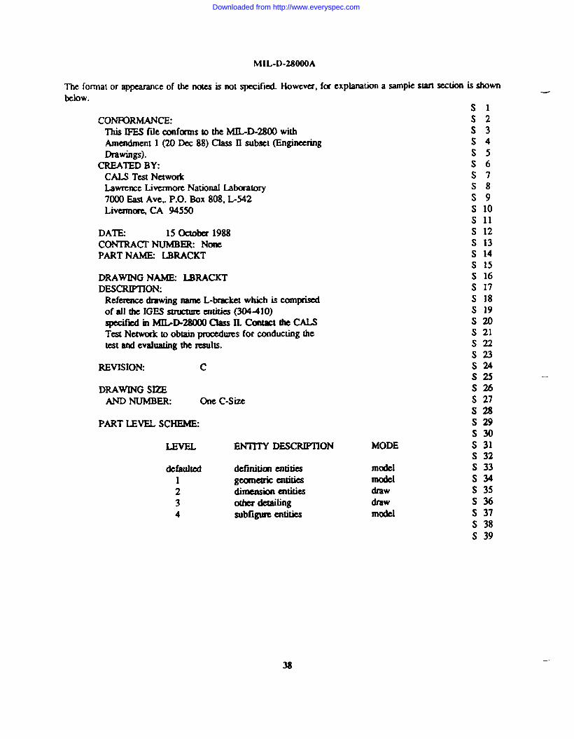
The format or appearanceof the notes is not spccifkl. I-iowcvcx,for explanationa samplestart sution is shownbelow.
S1CONFORMANCE: S2
This I?ES fde eonfums to the MIL-D-21UMwith S3Amendment 1 (20 WC 88) Class II subset (Engineering S4Drawings). S5
CREATEDBY: S6CM Test Network S7LawrenceLivcrmorc National hbaaumy S87000 East Ave,. P.O. Box 808, L542 S9Livemn~ CA 945S0 s 10
s 11DATE 15 Oetobet 1988 s 12CONTRACI’NUMBER None s 13PART NAME LBRACKT s 14
s 15DRAWINGNAME LBRACKT S 16DESCIUITION: s 17
Referencedrawing name L-bracket which is comprised S 18of all the IGES smKxureentities (304410) s 19apecifiiin IvWD-28000 Class ILcontactthecALs S20Test Network to obtain pl’OCCdLUCS for conducting the s 21test and evaluating the results, S22
S23REVISION c S24
S2S —
DRAWINGSEE S26AND NUMBER: one C-Size S 27
S28PART IJNEL SCHEME: S 29
S3QLEVEL ENTITY DESCMPTION s 31
S 32defaulted definiticmentities s 33
1 geunetric entities S342 dimension ez’ttitics s 353 orher daaiting S364 subfigure entities s 37
S 38s 39
MODE
modelmodeldrawdrawmodel
38—
Downloaded from http://www.everyspec.com
MIL-D-2SOOOA
6.5. AdditionalwocessinRCOfMiitiOnS Certain dditiomd ASME Y14.26M file pmcesaingpractices arcpreferred,but am not mandatory. Im&nemora ahoutd be swam of the foltowing RecommendedPraclices (RP),from the lGES RccommendcdPr&xicesGuide, which ftier specifyprefcxredprocessing algodhms.These inCh)dC
RP 2: Witness Line SuppressionRP 4: Transformation Matrix ProcessingRP 7: Maximum ComdinauvalueRP8: Independent Witness L-RP 15: Zuol?adiusArcsRP 16: Translation VectorRP 17: ModdspaccscakRP19: Imkpemknt and Dcpemht FkomssingRP 21: Comments in PD RecordsRP a: Representation of Linear StringsRP 27: Lirnitati(mson IxveI IdcmtifkraRP41: Entity Ident.ifkrsRP 42: Unique Names
6.6. Definitions.
6.6.1. Acronymsused in this specifkation Acronyms used in this spccifkation are defined as fotklws
a. ASME
b. CAD.
c. DE.
d. IC.
e. NC.
f. PC.
g. pD*
The Amaican Society of MechanicalEngineers
Computer Aided Design systems make use of intctaive graphics to enhance a- W@ to &f- the intendedpro&lcL
The D-tory Entry section of an ASME Y14.26M fde.
IntegMtedCilmlit.
Numerical Conuol.
printed C-it.
FhrarneteJdata section of an ASME Y14.26M f~.
6.6.2. Annotation. Text or symbo& oot part of the geomcxricmodel, which provide infmnation.
6.6.3. ADDlicationintemeted modeL An information model that describes the logical informationstmturm-f~~*g8@x*-tim du-ti~lmd~timmh= ~ a k~l of absuwtiofI that is $Wlcicnt for selecting the necessary IGES entities for an applkation
.
6.6.4. AmWation mtocol. Defines the context for the usc of product data and specifk.s the usc of the standardin that context to satisfy an industrial med.
39
Downloaded from http://www.everyspec.com

M[L-D-2MOOA
6.6.5. Apc)licm.ionrefercnccmodd. tiinfonfi tiltikwrik tic fflfotimsmct~mdconstraintsfmanapplicatkm area ~infodmmdelma~ltim~ifw terminologyandruksfamiliar to an expert from the application area.
6.6.6. Avulicationsubset. A sexof specific ASME Y14.26Mentities which are used to completely andunambiguously represent the information requirements of a product for a spccifkd applicatkm.
6.6.7. Associativity. A structure entity which defines a logical link benveen diffe!ententities.
6.6.8. Auribute. Informationwhich sexvesto qualify entity definition.
6.6.9. Dimetotycmbysection. That section of an ASME Y14.26M fde consisting of freed fwld data items fcxan index and attribute list of all entities in a fde.
6.6.10. -. The basic unit of informationm an ASME Y14.26Mf~ The tam applies to single itemswhich may be individti elements of geometry, colkctions of mmtatkm to form dimmsiomAa collections ofentities to folln smuctud entities.
6.6.11. Form numbw. AIIinteger which is used to furtha definea spccifii entity.
6.6.12. Rmmetez data section. A section of an ASME Y14.26Mf~ consisting of specificgecnnetricorammsativeinformationabout the entities or pointas to related entidcs.
6.6.13 Pos~. A prognun which tmnskms a fk of product deftition data from the ASME Y1426Mformat into the data base of a specif’cCAD/CAM system.
6.6.14, Prmomsor. A p’ogram which translates a fde of @uct definition data firm the data ~ of aspecific CADKAM system into the ASME Y14.26M format.
6.6.16. Roduct dcfmition data. Denotes the totality of data ekmcms required to compku]y defu a producL
product tkfitition data inchldes geometry, topology, dat.ionship, tolaances, aaributes, and features nmesswy tocompktely clef= a cunponent pm w tm assembly of parts for the purpose of design, amdysis, manufz=tl~~
6,6.17. RcmelWentity. A structure cmtitywhich allows numeric (r text infcmmation to be related to othwentities.
6.6.18. ~tart w!aiott. ‘he section of an ASME Y14.26M file ccmtainingthe human-rcadabk fik prologue.
6.6.19. Wire frame. A type of modeling that represents an object by its edges, fonmingan “outline”of theobject in curve segments.
40
Downloaded from http://www.everyspec.com

-.
MIL-D-28000A
6.7. Sub@tcm ~cyword) listing.
Application subsetsApplkalion protocolDigitalEngineeringdrawings ,Ekaxical applicmionsElectronic llJ@i=tiOnSIGESNurnaical ControlPipingI%odua dataTechnical illustdonsY1426M.
41
Downloaded from http://www.everyspec.com
MIL-D-28000A
custodiansArmy-mNavy - SHAir Force-24DLA - DH
Review activities:Army-AMAif Fofcc-ol,02NSA - NSDCA-DCNASA - NAOtha’s - NfST, DOE, GPO, N(2S
user adivitiexOSD-IRkrny - AL, AT, AV, E& ER, GL, ME, MI, MI?, SM. TE, TMNavy - AS, EC, OS, SA, YDAir Fonx -11, 13, 14, 17, 18, 19,68,79,99
Prcrmrinjz Activity
OSD-CL
42—
Downloaded from http://www.everyspec.com
.—
MIL-D.28000A
6.7. Subject tcmn(kcyword) listing.
Application subsetsAppkafion protocolDigitalEngineering drawings ,Ekurical applidonsElectronic a@iC?liOllSIGESNumericalControlPipingProduct dautTechnical illumuionsY14.26?VL
41
Downloaded from http://www.everyspec.com