Embed Size (px)
Citation preview
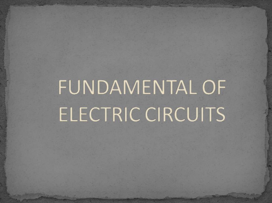

An electric circuit is an interconnection of electric elements. All elements can be interconnected in several ways. The circuit topology includes branch, node and loop.
A branch represents a single element. The point between two or more branches is called a node. A loop is any closed path in a circuit.
2
3 Nodes5 Branches3 Loops
3

Determine the number of branches and nodes in these figures.(a) (b)
(c)
4

vI RV = IR
Current in a circuit will always be proportional to the voltage and resistance presented
5

6

R = 0.In practice, a short circuit is usually a connecting wire assumed to be perfect conductor.
7

R = ∞.
8
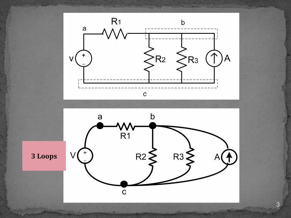
PV IP = VI
9

Two types:1. Kirchhoff’s Current Law (KCL).2. Kirchhoff’s Voltage Law (KVL).
10

Kirchhoff’s current law (KCL) states that the sum of currents entering the node is equal to the sum of currents leaving the node.
i1+i2 = i3+i4
11

Direction of current:It always flows from a higher potential (+ve) to lower potential (‐ve) of passive element.Generally,
Refer to the arrow of current source.It flows from +ve terminal of voltage source.
12

Kirchhoff’s voltage law (KVL) states that the sum of all voltages around a closed loop is zero.
The sign on each voltage is the polarity of the terminal encountered first as we travel around the loop.
It is either clockwise or counter clockwise.
13
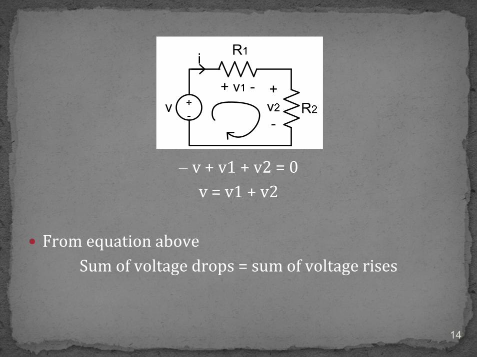
− v + v1 + v2 = 0v = v1 + v2
From equation aboveSum of voltage drops = sum of voltage rises
14

If v = 10 V, R1 = 2 Ω and R2 = 5 Ω, find i.
15
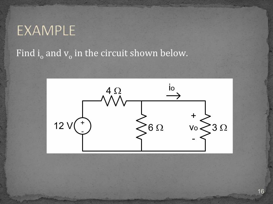
Find io and vo in the circuit shown below.
16

Two elements are in series if they share a single node and carry the same current.
v ≠ v1 ≠ v2i = i1 = i2
17
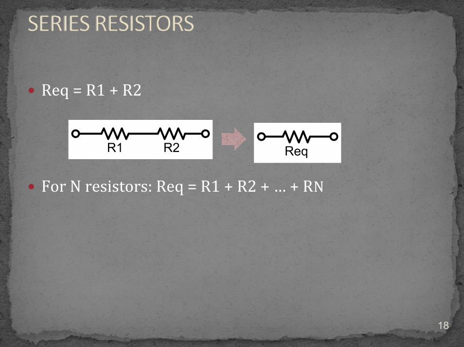
Req = R1 + R2
For N resistors: Req = R1 + R2 + … + RN
18

Determine v1 and v2 if v = 10 v, R1 = 2 Ω and R2 = 5 Ω.
19

v1 = [R1/(R1 + R2)]*vv2 = [R2/(R1 + R2)]*v
20
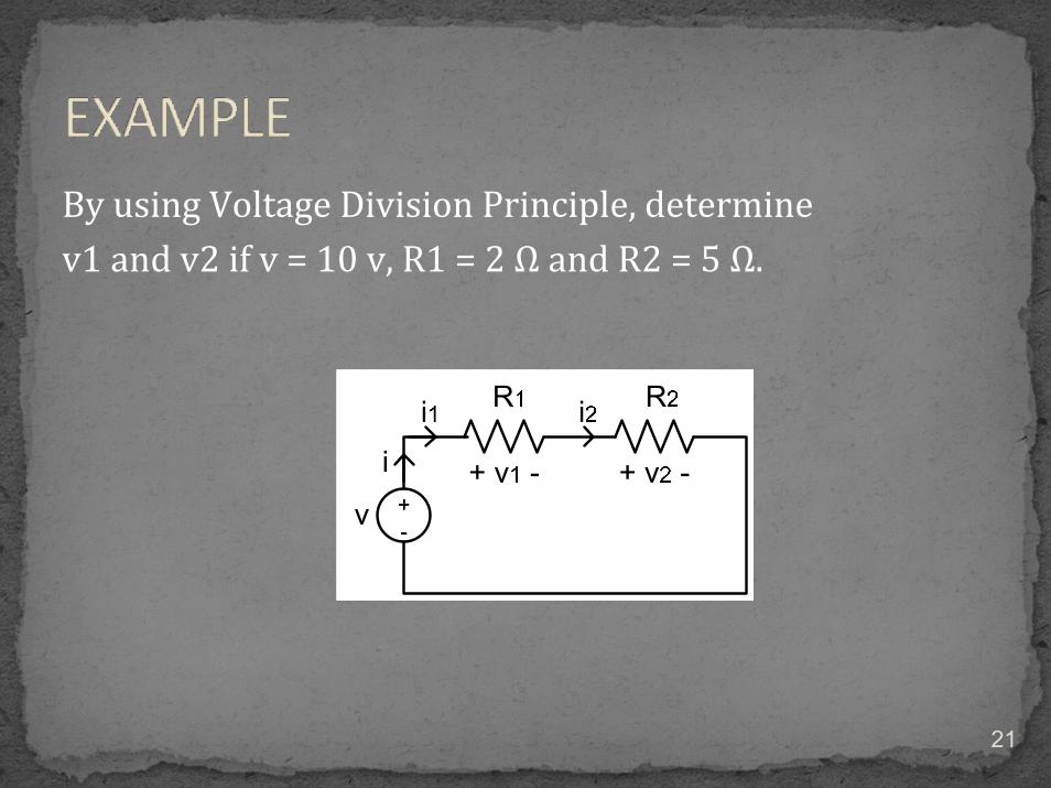
By using Voltage Division Principle, determine v1 and v2 if v = 10 v, R1 = 2 Ω and R2 = 5 Ω.
21

Two or more elements are in parallel if they are connected to the same two nodes and have the same voltage across them.
v =v1 = v2i ≠ i1 ≠ i2
22
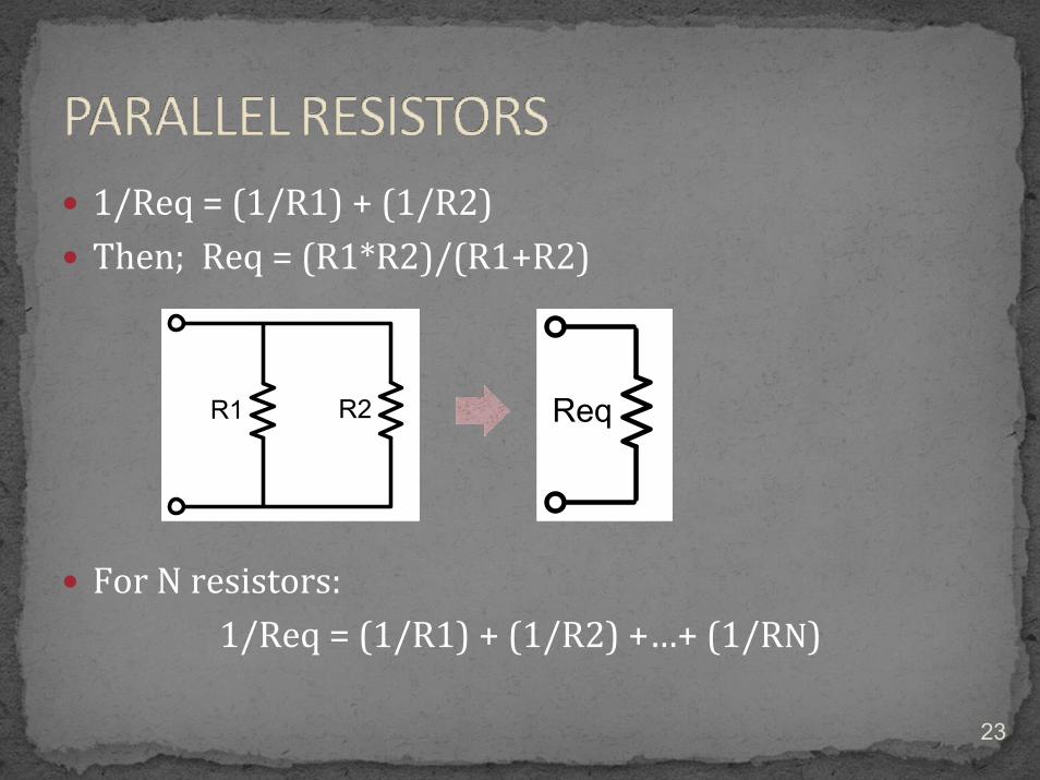
1/Req = (1/R1) + (1/R2)Then; Req = (R1*R2)/(R1+R2)
For N resistors: 1/Req = (1/R1) + (1/R2) +…+ (1/RN)
23
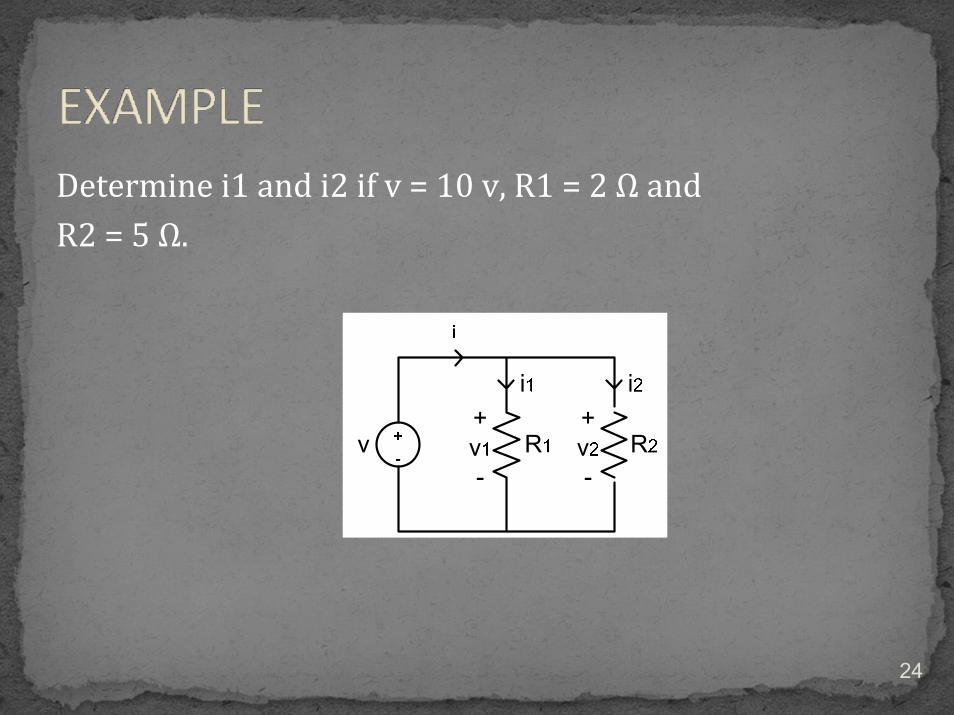
Determine i1 and i2 if v = 10 v, R1 = 2 Ω and R2 = 5 Ω.
24

i1 = [R2/(R1 + R2)]*ii2 = [R1/(R1 + R2)]*i
25

By using Current Division Principle, determine i1 and i2 if v = 10 v, R1 = 2 Ω and R2 = 5 Ω.
26

Circuits driven by sinusoidal current or voltage sources are called ac circuit.
A sinusoidal current is usually referred as alternating current (ac) which has positive and negative portions.
27

General equation/ steady‐state equation:
v(t) = Vm sin ωt
whereVm = the max. voltageω = angular freq. in rad/s
= 2πff = freq (50 Hz; Malaysia and 60 Hz; U.S.)
28

where θ = angle between voltage (v) and current (i).
v(t) = Vm sin ωt
i(t) = Im sin (ωt − θ)
AC Signal
29

It is a complex number that represents the amplitude and phase of a sinusoid.
It can be represented in 3 ways:Rectangular form.Polar form.Exponential form.
30
Rectangular form:
z = x + j y
Wherej = (−1)1/2 .x is the real part of z.y is the imaginary part of z.
31

Polar form:
z = | r | ∠ θ
Where| r | = (x2 + y2)1/2 represents the magnitude of z. tan − 1 (y/x) represents the phase of z.
32

Imaginary axis
Real axis
j
2j
r y
x
z
φ
33

RMS stands for root‐mean‐square.
It is statistical measure of the magnitude of a varying quantity.
This term is very importance because in actual practical, the rms value is the effective voltage that is used in practical or in theoretical analysis.
34

RMS voltageVrms = Vm / √2
RMS currentIrms = Im / √2
35

1. An ac signal is given as v(t) = 141.4 sin 314t. Determine the maximum voltage, the rms voltage and the frequency.
2. Find a steady‐state current if the rms current is 30 A and the frequency is 50 Hz.
36

It is the cosine of the phase difference between voltage and current.
PF = cos θ
where θ is the angle between voltage and current (θv −θi).
37

It is also the cosine of the angle of the load impedance.
The power factor also regarded as the ratio of the real power dissipated in the load to the apparent power of the load.
38

In ac circuit, there are three main components involved:
Resistor – R in Ohms (Ω)Inductor – L in Henry (H)Capacitor – C in Farad (F)
39

Z = RI = (V∠ 0°)/ R= |I| ∠ 0°
40
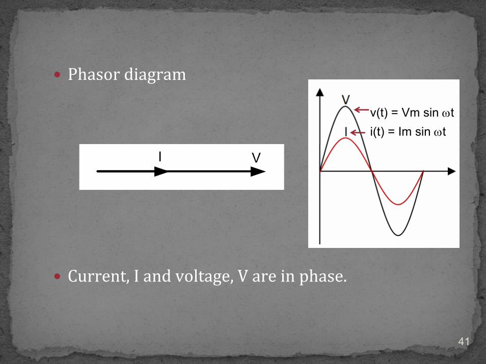
Phasor diagram
Current, I and voltage, V are in phase.
v(t) = Vm sin ωti(t) = Im sin ωt
41

Since the angle between V and I is 0, then the power factor will be
p.f. = cos θ= cos 0°= 1 or unity
42
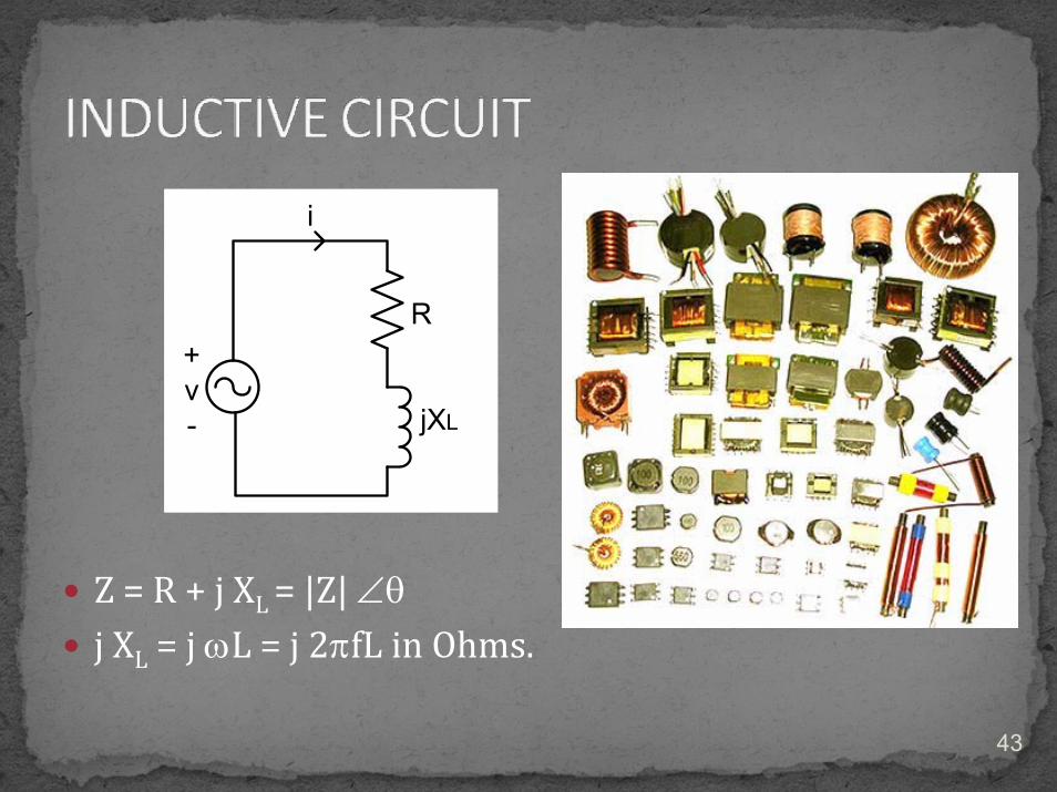
Z = R + j XL = |Z| ∠θj XL = j ωL = j 2πfL in Ohms.
L
43

I = (V∠ 0°)/ (|Z| ∠θ) = |I| ∠− θ
Phasor diagram
Current, I is lagging the voltage, V by θ degree.
Lagging direction
v(t) = Vm sin ωti(t) = Im sin (ωt − θ)
44

Since the angle between V and I is − θ, then the power factor will be
p.f. = cos θ lagging
45

Z = R + j XC = |Z| ∠− θ− j XL = − j (1/ωC) = − j (1/2πfC) in Ohms.
46

I = (V∠ 0°)/ (|Z| ∠− θ) = |I| ∠ θ
Phasor diagram
Current, I is leading the voltage, V by θ degree.
Leading direction
v(t) = Vm sin ωt
i(t) = Im sin (ωt + θ)
47

Inductive Load Capacitive Load
θ = + ve θ = − veCurrent LAG the voltage by θ
degreeCurrent LEAD the voltage by θ
degree
48

Z = R ± j X
|Z| = (R2 + X2)1/2
θ = tan −1 (X/R)
49

vI ZV = IZ
50

Find the steady‐state current for this circuit. Also find the phasor voltage across each element and construct a phasor diagram.
51

1. Find all currents flow through each element.2. Construct a phasor diagram showing all the currents
and the source voltage.
52

4 types:
1. Complex power, S.2. Apparent power, |S|.3. Real power, P.4. Reactive power, Q.
53

The product of the voltage across the load and the current through the load.
S = VI* where I* = I conjugate.
Unit: Voltage Ampere (VA)
54

If V = |V|∠0° and I = |I| ∠− θ
S = (|V|∠0°)(|I| ∠− θ)*= (|V|∠0°)(|I| ∠ θ)= |V||I| ∠ θ= |S| ∠ θ= P + jQ
55

The product of the voltage across the load and the current through the load whereby the phase angle are ignored.
|S| = |V||I|
Unit: Voltage Ampere (VA)
56

The real power@ active power @ average power @ dc power @ actual power supplied to the load.
P = |S| cos θ = |V||I| cos θ= |S|×PF = |V||I| ×PF
Unit: Watt (W)
57

The reactive power @ imaginary power represent energy that is first stored and then released in the magnetic field of an inductor or in the electric field of capacitor.
Q = |S| sin θ = |V||I| sin θ
Unit: Voltage Ampere Reactive (VAr)
58

S = P ± j Q
|S| = (P2 + Q2)1/2
θ = tan −1 (Q/P)
59

various elements are characterized by their ability to generate or absorb power:
P = +ve circuit will absorb real power.P = −ve circuit will generate real power.Q = +ve circuit absorb reactive power. Q = −ve circuit generate reactive
power.
60
Inductive load: it is consuming both real and reactive power from the source.
PXL = +ve and QXL = +ve
Capacitive load: it is consuming real power from the source and supplying reactive power to the source
PXC = +ve and QXC = ‐ve.
61
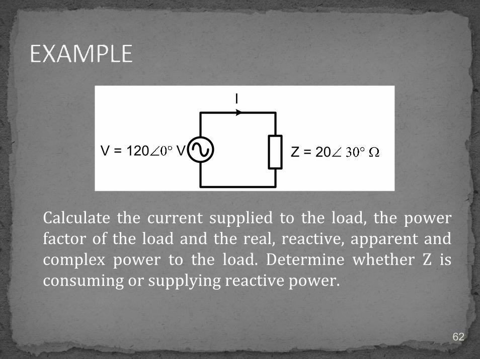
Calculate the current supplied to the load, the power factor of the load and the real, reactive, apparent and complex power to the load. Determine whether Z is consuming or supplying reactive power.
62

1. A load draws 25 kVA at a power factor of 0.85 lagging from a supply of 240 V. Calculate a) the real and reactive power to the load and b) the load impedance.
2. A load draws 15 kVA at a power factor of 0.85 lagging from a supply of 240 V. Calculate; a) real and reactive power to the load, b) the load current and c) the load impedance.
63

PF is the cosine of the phase difference between voltage and current, PF = cos θ.
Any load with low PF draws more current than a load with high PF for the same amount of useful power transfer.
The high current increases the energy lost and requires large wire and other equipment.
64

In Malaysia, the minimum power factor specified by TNB is 0.85.
To improve power factor, power companies install bank of capacitors (injecting Q).
This capacitor is connected in parallel with the load.
65
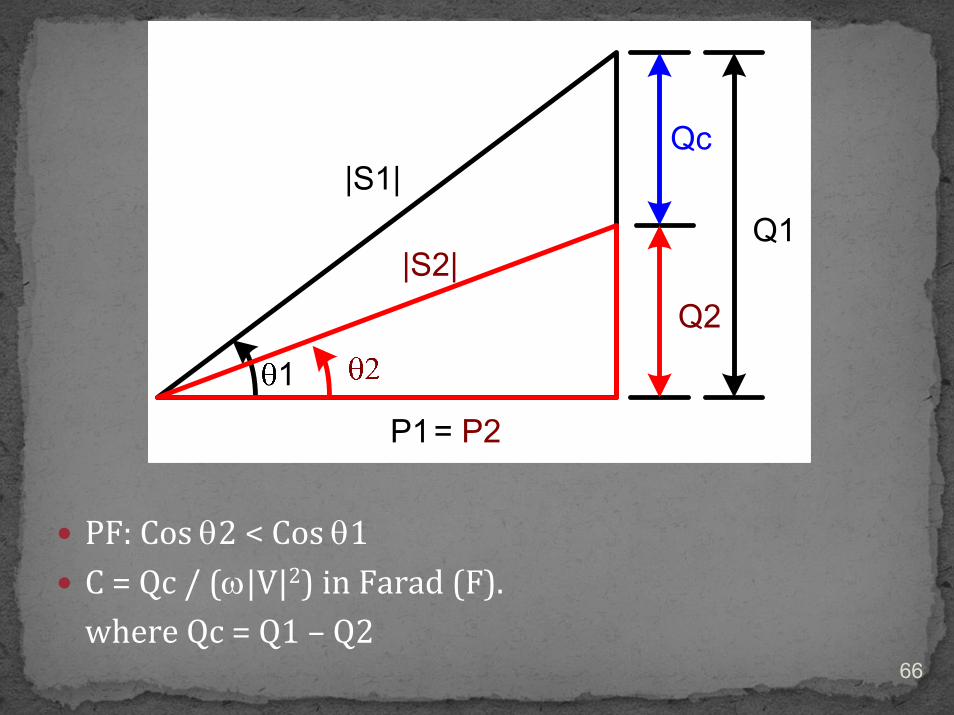
PF: Cos θ2 < Cos θ1C = Qc / (ω|V|2) in Farad (F).where Qc = Q1 – Q2
66

One load Z = 25 ∠ 30° is connected with a 120 V, 50 Hz source. Calculate the capacitance value that needed to improve the overall power factor to 0.95 lagging.
67

Van = |V| sin ωtVbn = |V| sin (ωt – 120°)Vcn = |V| sin (ωt – 240°)
68
It consists of generators, transmission lines and loads .
All three loads have same value of impedance.
All 3‐φ voltages generated are having same amplitude but displaced in phase by 120°.
69

Phasor diagram (abc sequence)
Van = |V| sin ωtVbn = |V| sin (ωt – 120°)Vcn = |V| sin (ωt – 240°)
70

The advantages of 3‐phase system:
1. It is possible to get more power per kilogram of metal from 3‐phase machine.
2. The power delivered to a 3‐phase load is constant at all times instead of pulsating as it does in 1‐phase system.
3. The 3‐φ motor having constant torque, start and run much better than 1‐φmotor.
71

There are 2 connections in three phase system namely:
Star/ Wye connection – YDelta/ Mesh connection ‐ ∆
72

73

The phase voltages ( line to neutral voltages):
VAN = |V| ∠ 0°VBN = |V| ∠ − 120°VCN = |V| ∠ − 240° = |V| ∠ 120°
where |V| is the magnitude of phase voltage
74

The line voltages (line to line voltages):
VAB = VAN − VBN = √3 |V| ∠ 0°VBC = VBN − VCN = √3 |V| ∠ − 90°VCA = VCN − VAN = √3 |V| ∠ 150°
where |V| is the magnitude of phase voltage
75

Phasor diagram
76

Since VAB, VBC and VCA are all line voltages and V is the phase voltage, then
|Vline| = √3 |Vph|
|Iline| = |Iph|
77

78

The phase currents:
IAB = |I| ∠ 0°IBC = |I| ∠ − 120°ICA = |I| ∠ − 240°
where |I| is the magnitude of phase current
79

The line voltages:
IA = IAB − ICA = √3 |I| ∠ − 30°IB = IBC − IAB = √3 |I| ∠ − 150°IC = ICA − IBC = √3 |I| ∠ 90°
where |I| is the magnitude of phase current
80

Phasor diagram
81

Since IA, IB and IC are all line currents and I is the phase current, then
|Vline| = |Vph|
|Iline| = √3 |Iph|
82

Features YConnected ∆Connected
Voltage magnitude |Vline| = √3 |Vph| |Vline| = |Vph|
Current magnitude |Iline| = |Iph| |Iline| = √3 |Iph|
abc phase sequence Vab leads Va by 30° Ia lags Iab by 30°
83
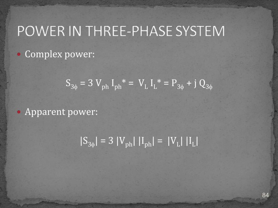
Complex power:
S3φ = 3 Vph Iph* = VL IL* = P3φ + j Q3φ
Apparent power:
|S3φ| = 3 |Vph| |Iph| = |VL| |IL|
84

Real power:
P3φ = 3 |Vph| |Iph| cos θ = |VL| |IL| cos θ
Reactive power:
Q3φ = 3 |Vph| |Iph| sin θ = |VL| |IL| sin θ
85
The current in the neutral of the balanced Y‐connected loads is In = Ia + Ib + Ic = 0.
Since the neutral carries no current, a neutral wire of any impedance may be replaced by any other impedance, including a short circuit and an open circuit.
86

Single‐Phase Circuit for Per‐Phase Analysis
87

Steps of analysis:1. Determine the voltages, currents and powers at
various points in the circuit with a per‐phase equivalent circuit. (phase voltage and current).
2. Convert all ∆‐connected load to Y‐connected load: ZY = Z∆ / 3
3. Draw the per‐phase equivalent circuit.4. Solve it as common circuit in circuit theory.
88

A three‐phase, Y connected system has 200 V effective line voltage and an equal impedance of (3 + j 4) Ω. Determine the line currents.
89

A balanced 415V, 50Hz delta‐connected generator supplies a star‐connected load, comprising three single‐phase impedances, each of 20 + j12 Ω. The line impedance is 0.02 + j 3.5 Ω. Determine (a) the line current, (b) the phase voltage across the load, (c) the line voltage at the load terminals and (d) the real, reactive and complex power of the load including power factor.
90

It provide a compact way to represent the interconnections of a power system.
The voltage and types of connections of each generator and load are usually shown on the diagram.
91

G1
Load 1
Load 2 -connected
Y-connected
Bus 1
Y-connected
92
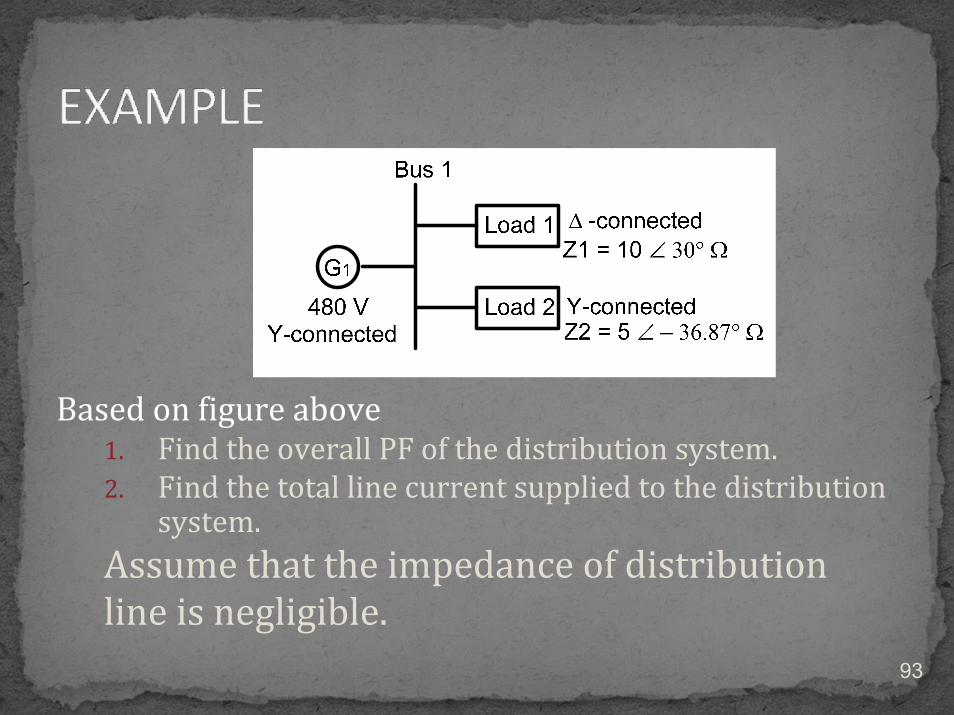
Based on figure above1. Find the overall PF of the distribution system.2. Find the total line current supplied to the distribution
system.Assume that the impedance of distribution line is negligible.
93