Embed Size (px)
Citation preview

not SCI-FI

ww
w.a
ldec
.co
m
Agenda
› A few words about transactors › SCE-MI use cases › Customer case studies
2

ww
w.a
ldec
.co
m
Transactions – A Higher Level (than RTL)
› RTL – verification bottleneck hence higher level - transaction › Higher abstraction
› Faster design entry
› Faster simulation
› Easier IP reuse
› New possibilities › Early HW/SW integration
› Software development
› Architectural analysis
3

ww
w.a
ldec
.co
m
Synthesisable Transactors 4
› Transactor is an adapter between the TLM and RTL › Translates function calls to sequence of bits
› SCE-MI describes how to move it to hardware › So a single transfer triggers many clock cycles and pin toggles
› Eliminates bottleneck by reducing bandwidth

ww
w.a
ldec
.co
m
SCE-MI Versions 5
› Macro-based – been on market for years › Function-based – popular, uses SystemVerilog DPI › Pipes-based – not as popular, doesn’t have clear advantages

ww
w.a
ldec
.co
m
Macro vs. DPI 6
Macro based Function based (DPI)
Abstraction level Low (closer to RTL) Medium (closer to TLM)
Clock control Explicit (full control) Implicit
Programming model Predefined API User defined API (API-less)
Ease of use Easy Intuitive
Migration from simulation to emulation
Easy with Aldec SceMiSim
Easy by design (most simulators support DPI)

ww
w.a
ldec
.co
m
SCE-MI Macro-based use Model 7
› Easy to use › Two modules in RTL code pass messages to and from software
› Simple dual-ready handshake protocol
ww
w.a
ldec
.co
m
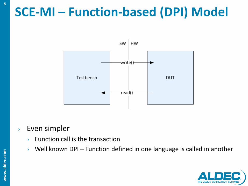
SCE-MI – Function-based (DPI) Model 8
› Even simpler › Function call is the transaction
› Well known DPI – Function defined in one language is called in another

ww
w.a
ldec
.co
m
9

ww
w.a
ldec
.co
m
Connecting with OVM/UVM 10
› UVM improves verification productivity › 3C – Constraints, Checkers, Coverage
› Thin C layer required › Both SCE-MI and DPI assume that testbench and design are in different
languages

ww
w.a
ldec
.co
m
Testing Against Executable Specification 11
› Executable specification model reused to test the low-level implementation
› Same stimuli applied to both modules – results compared automatically
› Coverage measured to control constrained random generation of transactions

ww
w.a
ldec
.co
m
Connecting Modules in the Modeling Stage and Already Implemented in RTL
12
› SCE-MI is the ideal choice to bridge implementations on different abstraction levels
› Incrementally move from simulation to hardware verification › as models are available in RTL
› to benefit from a much higher speed than in simulation

ww
w.a
ldec
.co
m
Ease of Virtual Prototyping 13
› No additional hardware
› No cables › No problem!
ww
w.a
ldec
.co
m
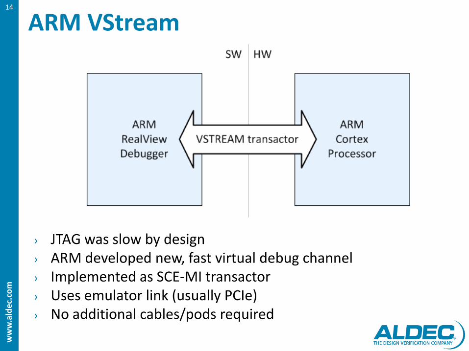
ARM VStream 14
› JTAG was slow by design › ARM developed new, fast virtual debug channel › Implemented as SCE-MI transactor › Uses emulator link (usually PCIe) › No additional cables/pods required
ww
w.a
ldec
.co
m
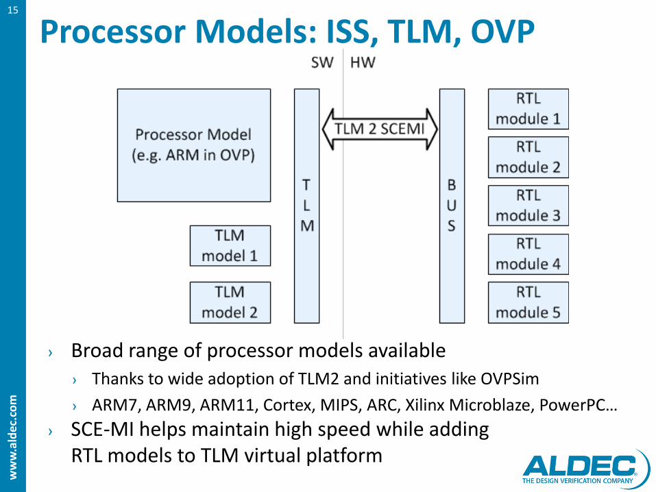
Processor Models: ISS, TLM, OVP 15
› Broad range of processor models available › Thanks to wide adoption of TLM2 and initiatives like OVPSim
› ARM7, ARM9, ARM11, Cortex, MIPS, ARC, Xilinx Microblaze, PowerPC…
› SCE-MI helps maintain high speed while adding RTL models to TLM virtual platform

ww
w.a
ldec
.co
m
QEMU 16
› Free processor emulator with efficient binary translation › Can be combined with SCE-MI hardware emulation
› Software developers develop drivers testing them with actual hardware, having full hardware visibility when needed
› Hardware tested with stimuli from real applications

ww
w.a
ldec
.co
m
17

ww
w.a
ldec
.co
m
Customer Requirements
› 3 stages with smooth transitions › Simulation with UVM
› Emulation with SCE-MI transactors
› In-circuit emulation + SCE-MI transactors
› Same C tests reused in all stages
› 5 months › HES-7 with Virtex-7 › 10+ interfaces
18

ww
w.a
ldec
.co
m
SoC application example 19
› Massively multicore › 20M+ ASIC gates

ww
w.a
ldec
.co
m
Stage 1 – Simulation with UVM 20
› UVM testbench but driven also from Tensilica Xtensa Instruction Set Simulator with Transaction-level interface

ww
w.a
ldec
.co
m
Stage 1 to Stage 2 Transition 21
› UVM Drivers are replaced with versions using DPI to communicate with SCE-MI transactors in hardware

ww
w.a
ldec
.co
m
Stage 2 22
› Finally CPU is moved to hardware › Network on Chip instead of TLM

ww
w.a
ldec
.co
m
Stage 3 23
› ICE – interfacing to the real world › Ethernet, PCIe, SPI 4.2, JTAG, etc.
› Speedbridges instead of transactors
ww
w.a
ldec
.co
m
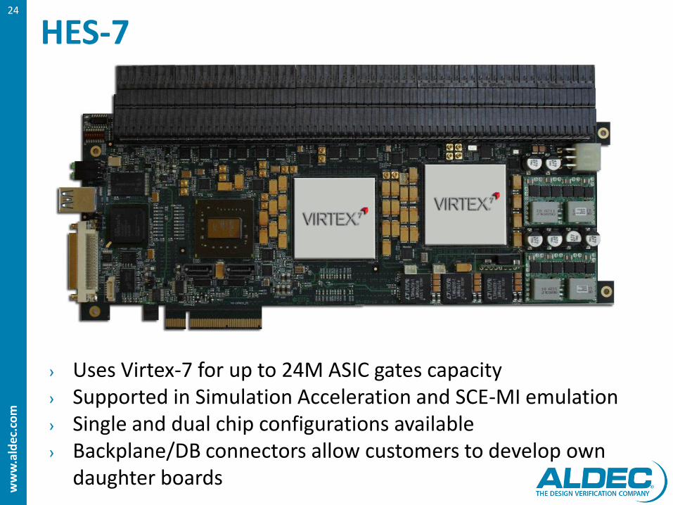
HES-7 24
› Uses Virtex-7 for up to 24M ASIC gates capacity › Supported in Simulation Acceleration and SCE-MI emulation › Single and dual chip configurations available › Backplane/DB connectors allow customers to develop own
daughter boards

ww
w.a
ldec
.co
m
HES-7 x4 25
› Backplane/DB connector and HES-7 backplane › Can connect x4 HES-7 cards › Up to 96M ASIC gates › Up to 64GB DDR3 Memory › High speed 25 Gb/s I/O connections

ww
w.a
ldec
.co
m
26

ww
w.a
ldec
.co
m
Customer Requirements
› Evolution of emulator use › Reuse of 3rd party prototyping boards
27

ww
w.a
ldec
.co
m
SoC - Mobile Processor
› Dual-core › 30M+ ASIC Gates
28

ww
w.a
ldec
.co
m
Emulation - Initialisation Phase
› AXI transactions generated and monitored in SystemC › Backdoor access to memories (e.g. initializing program code) › JTAG cable connected to pins
29

ww
w.a
ldec
.co
m
Emulation - Initialisation Phase IMPROVED
› JTAG transactor connects to Eclipse or GDB through OpenOCD › Instead of using JTAG pod
30

ww
w.a
ldec
.co
m
Emulation – Production Phase
› Flexible – can use TLM or RTL for almost each model › AXI SCE-MI transactors connect
› RTL running in hardware
› TLM models running on virtual platform
31

ww
w.a
ldec
.co
m
Reusing Proto Boards
› Off-the-shelf FPGA boards
› Reuse for emulation
› Reuse for simulation acceleration
› Better return on assets
› Reduces capital spending
32

ww
w.a
ldec
.co
m
Q & A
Aldec, Inc. Corp. Headquarters – N. America 2260 Corporate Circle Henderson, NV 89074 USA
+1.702.990.4400 [email protected] Europe [email protected]
Israel [email protected]
Japan [email protected]
China [email protected]
India [email protected]
Taiwan [email protected]
www.aldec.com News/Products/Events/Resources/Support
33
Riviera-PRO™ Advanced Verification Platform
Active-HDL™ FPGA Design and Simulation
ALINT™ Design Rule Checking
HES™ Hardware Emulation Solutions
DO-254/CTS™ FPGA Level In-Target Testing
HES-7™ ASIC Prototyping
Microsemi™ Prototyping RTAX/RTSX