Embed Size (px)
Citation preview

NOT FOR PUBLICATION Circ PS-2283 August 2001
REPORT
of the Meetings of the
API SUBCOMMITTEE ON DRILLING & SERVICING EQUIPMENT/ DRILL STEM ELEMENTS & COMPOUNDS
(SC 7)
at the 2001 Standardization Conference
of the Upstream Department
American Petroleum Institute
Hyatt Regency Hotel Calgary, Alberta, Canada
June 25 -27, 2001
AMERICAN PETROLEUM INSTITUTE Upstream Department
1220 L St., NW Washington, DC 20005 Phone: (202) 682-8000 Fax: (202) 962-4797

The following meetings were held during the conference: Task Group on Drilling and Well Servicing Structures (TG 1)
Monday, June 25, 2001 8:30AM – 12 Noon Bob Donnally, Chair
Resource Group on Threading and Gauging of Rotary Shouldered Connections (RG1) Monday, June 25, 2001 8:30AM – 12:00 Noon Tony Collins, Chair Task Group on Drilling Equipment/Hoisting Equipment/Wire Rope (TG 3)
Monday, June 25, 2001 1:00PM – 5:00PM Mark Sibille, Chair
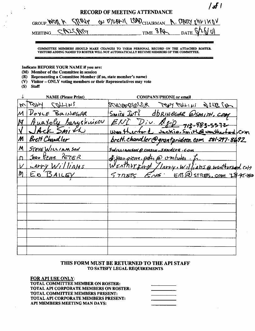
Work Group on Dynamic Loading of Drill Strings (TG4/WG 2) Tuesday, June 26, 2001
8:00AM – 9:00AM Anatoly Baryshnikov
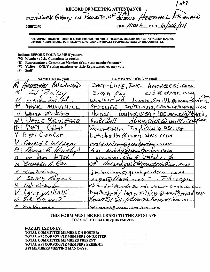
Work Group on Rewrite of RP 7A1 (TG4/WG 1)
Tuesday, June 26, 2001 11:00AM – 12:00 Noon Herschel McDonald, Chair Task Group on Drill Stem Elements & Compounds (TG 4) Tuesday, June 26, 2001 1:00PM – 5:00PM Jack Smith, Chair
Subcommittee on Drilling & Servicing Equipment/Drill Stem Elements & Compounds (SC 7)
PART 1 – Drilling and Servicing Equipment PART 2 – Drill Stem Elements & Compounds Tuesday, June 26, 2001 Wednesday, June 27, 2001 1:00PM – 3:00PM 9:00AM – 12:00 Noon
Jim Hall, Chair
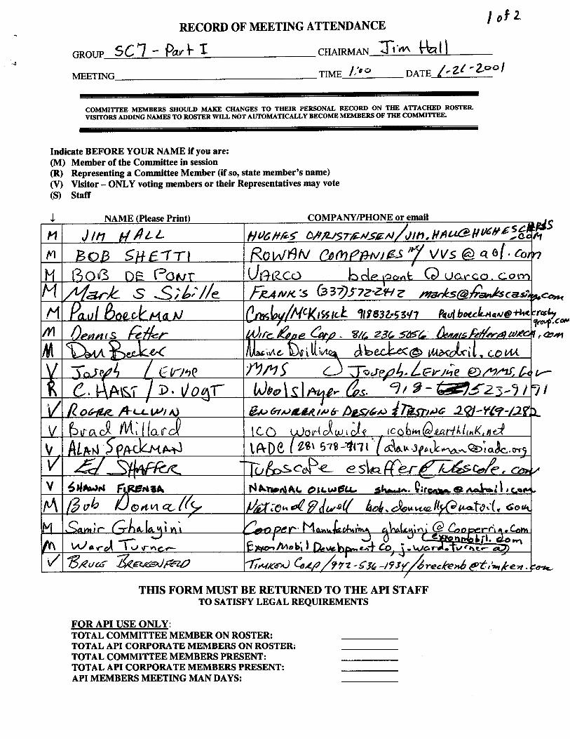
Note: See Appendix A for all Attendance Rosters.

COMMITTEE 7 LEGEND
Circ. PS-2203 1999 Standardization Conference Agenda Circ. PS-1918 1990 Standardization Conference Report Circ. PS-1950 1991 Standardization Conference Report Circ. PS-1983 1992 Standardization Conference Report Circ. PS-2000 1993 Standardization Conference Agenda Circ. PS-2017 1993 Standardization Conference Report Circ. PS-2034 1994 Standardization Conference Agenda Circ. PS-2051 1994 Standardization Conference Report Circ. PS-2071 1995 Standardization Conference Agenda Circ. PS-2089 1995 Standardization Conference Report Circ. PS-2105 1996 Standardization Conference Agenda Circ. PS-2121 1996 Standardization Conference Report Circ. PS-2137 1997 Standardization Conference Agenda Circ. PS-2153 1997 Standardization Conference Report Circ. PS-2171 1998 Standardization Conference Agenda
Circ. PS-2187 1998 Standardization Conference Report Circ. PS-2203 1999 Standardization Conference Agenda
Circ. PS-2219 1999 Standardization Conference Report Circ. PS-2235 2000 Standardization Conference Agenda Circ. PS-2251 2000 Standardization Conference Report Circ. PS-2267 2001 Standardization Conference Agenda Circ. PS-2283 2001 Standardization Conference Agenda

1
Report
API Subcommittee 7 – Drilling and Servicing Equipment Standardization Conference Calgary, Alberta, Canada
June 25-27, 2001 Chairman: Jim Hall
Call to Order The meeting of this subcommittee was split into two sessions for this conference. Chairman Jim Hall called each to order and passed around attendance rosters (see Appendix A for all attendance rosters). Part I covered items from TG1-Drilling and Well Servicing Structures and TG3 – Drilling Equipment/Hoisting Equipment/Wire Rope. An API award and an ISO Certificate of Appreciation were given to Mark Sibille in this meeting. Part 2 covered items from RG1- Threading and Gauging of Rotary Shouldered Connections and TG4 – Drill Stem Elements and Compounds. Review and Approve Previous Meeting Minutes The previous meeting minutes were approved without change. Task Group Reports TG1-Drilling and Well Servicing Structures – Report given by Chairman Bob Donnally The following actions were agreed relative to the four active work items under this group: 4F00-1 Seismic Criteria, Calculations and Structural Safety Limits for Masts and Derricks Ward Turner reported that the scope of this work has been narrowed to cover only offshore
structures. A TG draft paper is almost complete and should be ready for distribution by 12, 2001.
4F00-2 Wind Criteria, Calculations, Calibration and Assessment for Masts and Derricks The JIP wind tunnel testing at Texas A&M should be complete sometime next spring. The TG draft covering the results will then be written.
4F00-3 Structural Engineering for Masts and Derricks A new leader has been selected for this work and a TG draft is planned for June, 2002 4F98-11 Evaluation of ESSO Mast Failure
The necessary information has not been obtained covering this matter. Bob Donnally will write a letter to Nabors Drilling and Esso requesting release of this information. No time for TG draft can be set.
The group stated that a review was being conducted on the need for modification of maintenance and repair documents. The group would also investigate the need for added content in Spec 4F addressing safety issues in design standards. New Work Item SC701-4 was submitted and approved to revise RP 4G (See appendix B for NWI). No ballot items were submitted.
TG3 – Drilling Equipment/Hoisting Equipment/Wire Rope – Report given by Chairman Mark Sibille Hoisting and Drilling Equipment The group agreed to submit ISO 13534 and 13535 for letter ballot approval to replace the current RP8B and Spec 8C. The group discussed significant changes in content that should be included in

2
Spec 8C to remove errors and ambiguity as covered by NWI SC701-1. The group voted to submit these changes for letter ballot approval. The NWI proposal for modified NDE requirements was not supported by the group and dropped from the agenda. The group will investigate the continued need for Spec 8A and consider possible changes or elimination. Wire Rope The group will investigate adoption of ISO/TC105/FDIS10425 as a replacement for API Spec9A. Approval from TC105 is required. Changes to RP9B submitted on NWI SC700-1 at the last meeting were approved for letter ballot vote. An NWI will be created to expand the wire rope sizes in RP9B. The group discussed significant changes in content that should be included in Spec 7K to remove errors and ambiguity as covered by NWI SC701-2. The group voted to submit these changes for letter ballot approval. It was also requested that ISO/SC4/WG1 agree to resubmit ISO14693 as DIS2 with these changes rather than proceed to FDIS in the current condition. A total of eleven items were submitted for letter ballot approval. TG4 – Drill Stem Elements and Compounds – Report given by Chairman Jack Smith The following actions were taken relative to the three active work items under this group: 1.83-E Review of RP7A1
Work on this item is progressing, however, June, 2002 is the soonest that a TG draft on this item will be available. Mike Spanhel reported that no funding would be available for this work next year.
SC798-1 Tool Joint Tensile Yield at Recommended Make-up Torque Several changes were made to this proposal at this conference. January, 2002 is the soonest that a TG draft will be available with these changes.
SC798-2 High Strength Drill String Identification Markings After significant discussion, the subcommittee voted to return this item to the task group for revision. The group determined that considerably more work and coordination with ISO SC5 was needed.
The subcommittee voted to request that SC5 work group on ISO 11961 attempt to assure harmony between their work and the work in this subcommittee. All of the ISO documents that are being created covering Spec7 and RP7G content are progressing but are behind schedule. TG4/RG1 – Threading and Gauging of Rotary Shouldered Connections – Report given by Chair Tony Collins The ISO document covering this material is planned to include some “non-API” connections as non-preferred threads. Work is progressing to produce an auditable procedure covering gage calibration. Funding will be available next year to replace some of the Grand Master Gages. A list of available Regional Master Gages may be added to the API website. No ballot items were submitted Adjournment With no further business to be handled, the meeting was adjourned.

3
Report API SC7/TG1 – Drilling and Well Servicing Structures
Standardization Conference Calgary, Alberta, Canada
June 25, 2001 Chairman: Bob Donnally
Call to Order Chairman Bob Donnally called the meeting to order at 8:35 AM. Minutes of the June 2000 conference were read and accepted. A comment was made that the “minutes” published in the Agenda from API are not official minutes, and contain considerable editorial work. The minutes approved by the task group were the actual hand written minutes taken at the June 2000 meeting. Color Coding There was a brief discussion regarding color-coding of spec 4F. Andy Radford committed to have the spec color coded by the API staff, and sent out to task group members for review. JIP Status Ward Turner gave a brief status report on the JIP for “Measurement of Wind Load Resistance on Drilling Structures”, as follows; The JIP was funded and started approximately 1 year ago. Participants include drilling contractors, oil companies, government agencies such as the MMS and HSE, the IADC, and third tier participants such as equipment manufacturers and designers. The JIP is being managed by Stress Engineering with Dave Lewis acting as Technical Manager. Stress Engineering is managing the wind tunnel test, which is scheduled to take place late summer or early fall, at Texas A&M. The objectives of the test include an attempt to better understand the science of the wind acting on a complex structure, and to provide a means to calibrate the calculated values. Other JIP activities include completion of a database of information on drilling structures from drilling contractors, completion of “Best Practice” calculations, and completion of part of the desktop analysis of selected structures. Information to date has shown an extremely wide variation in calculated wind resistance forces from different designers. The JIP schedule indicates completion of the current phase by the summer of 2002. The JIP members will then decide if the results are acceptable for release. ESSO Tuna Failure Findings This incident was discussed briefly and the chairman (Bob Donnally) was requested to send a formal request for a report on these findings to ESSO and to Nabors drilling. Papers / Open Work Items The JIP is one part of an overall effort begun several years ago to provide potential enhancements to the 4F specification. Open work items exist to provide papers on these enhancement subjects. The papers on Seismic and General Structural were discussed.

4
Ward Turner stated that the paper on seismic was essentially complete with the exception of incorporating the results of comments from others in the work group. Ward agreed to complete this effort and send the paper around for review. This paper will cover seismic for offshore rigs only. The paper on General Structural is headed by Mike Effenberger, who was not present at the meeting. Mike is heavily involved in the JIP work, and has not been able to work on the structural paper. Ward Turner moved that, provided Mike Effenberger was in agreement, Samir Ghalayini be put in charge of this paper to expedite its completion. The motion passed. Bob Donnally will contact Mike to discuss and coordinate this change. API Funding At the June 2000 meeting, Mark Trevithick had been assigned to head a group to determine the scope of work required to complete the open Work Items (papers). This work scope could then be used establish a cost and possible request for funding from API. Mark was not available to report on this item. It was agreed this item is important and should be continued. RP on Inspection and Repairs / Modifications to Existing API Structures Robert Urbanowski reported on this group’s activities in place of Dewayne Vogt, who could not be present. The group has met two times during the year, and has identified a number of issues, including recommended inspection intervals, corrosion problems, modifications to change the structures intended use, and damage to the structures. Triggers for inspection discussed included, time intervals, change in type of drilling, change in risk of the operation, and damage. The group includes members from drilling contractors, manufacturers, and oil companies. The next meeting is scheduled for August 14th at the offices of the Lewco Company in Houston. Safety Concerns The subject of man riding winches and general items, which effect personnel safety on the rig floor and in the derrick, was discussed. Alan Spackman pointed out that some of these items are covered from a recommended usage standpoint in the IADC “Accident Prevention Reference Guide”. Several standards, including NPD, were mentioned in regards to the man riding winches. The question was raised, should API add standards to cover any of these items, or possibly reference to other standards, which cover these items. Norm Dyer moved that the Chairman request guidance from SC7 or C3 on this issue. The motion passed. Robert Urbanowski made a motion that structural safety items such as safety platforms, pad eye testing, etc. be considered by the structural paper work group. The motion passed. The meeting was adjourned at approximately 11:50 AM.

5
Report API SC7/TG3 – Task Group on Hoisting Equipment, Wire Rope, and Drilling & Well
Servicing Equipment Standardization Conference Calgary, Alberta, Canada
June 25, 2001 Chairman: Mark Sibille
1. Open Meeting 2. Attendance list 3. Accept minutes of last meeting 4. Old Business - Hoisting Equipment
a. Item 1001: Existing Agenda Item 3.43 - report on ISO activities i. ISO 13534 & 13535 were published as of 12/2000 ii. ISO 14693 is scheduled for FDIS circulation in Aug 2001 iii. The NWI for an ISO equivalent to RP7L has not yet been filed due to the
current work load. b. Item 1002: Addenda to API Specs 8A and 8C issued May 2001
5. New Business - Hoisting Equipment
a. Item 1003: Review of ISO 13534 for possible adoption as API RB 8B i. Motion by Reidar Johansen ii. Second by Paul Boeckman iii. Motion:
Letter Ballot: Adopt ISO 13534 as API RP 8B
iv. Motion Carried
b. Item 1004: Review of ISO 13535 to see if the year 2001 Addenda to API 8C is included in the ISO document. i. To be reviewed and compared to 8C addenda to determine differences
(Larry Foley) ii. Discussion: Adoption of ISO 13535 as ISO/API 8C
a) Norm Dyer asked if the motion includes addenda to 8C” b) Tom suggested that the review be included in the letter ballot to
expedite passage instead of waiting another year iii. Motion by: Reidar Johansen iv. Second by: Tom Becker v. Motion:
Letter Ballot: Adopt ISO 13535 as API Specification 8C
vi. Motion Carried
c. Item 1005: NWI by Mr. Eugene Reinhart regarding NDE of forgings and castings (attached to the agenda). The NWI is not fully completed (ref page 2 of the NWI). The question is as to what is the position of TG3 with regard to this NWI. There is a question as to whether API is the correct forum to propose any

6
changes in the methods used in these standards or if that should be a question for the organization that developed and maintains these standards referenced by API. (Ref. Letter by Tom Becker) i. Discussion:
a) Tom pointed out that the NWI challenges the acceptance criteria and MPI process. The current specification has been agreed to by an international group of experts. ASTM is capable of maintaining their specification. ASME references the same ASTM specification that API specifications reference. ASTM provides for proving the sensitivity of a process. It is not the responsibility of API to change the ASTM specification. Perceived problems with the MPI processes used should be referred to ASTM.
b) Samir Ghalayini noted that he has witnessed varying results from different techniques and methods.
c) Norm Dyer stated that the differences in results can be explained by differences in techniques or operator error.
ii. Motion by: Dan Becker iii. Seconded by: Robert Urbanowski iv. Motion: That TG3 will not pursue the proposed NWI and will drop it
from the agenda v. Motion Carried
d. Item 1006: API Specification 8A
i. Discussion on the question of withdrawal of Specification 8A a) Norm - API would walk away from segment of industry. Spec is
being used. Incorporate features of 8A into 8C. Do not abandon segment of industry.
b) Samir - some provisions of 8A are not needed in 8C c) Paul Boeckman stated that he get requests for 8A equipment. Some
of his customers are not educated on 8C. There is a need to educate users on 8C.
d) Tom pointed out that 8A has not changed since 8C was introduced. He questioned how many manufacturers make 8A equipment that does not actually meet the requirements of 8C.
e) Mark reported that there are some older models of 8A equipment that are in use and for sale today, but that are not qualified to 8C.
ii. Motion by: Bob DePont iii. Seconded by: Larry Foley iv. Motion: Withdraw API Spec 8A v. Motion withdrawn by Bob DePont vi. Discussion on incorporating Spec 8A into Spec 8C as PSL 0
a) Tom Becker stated that inclusion of a PSL 0 would invalidate 8C. vii. Motion by: Reidar Johansen viii. Seconded by: Norm Dyer ix. Motion:
To create a workgroup to study need for 8A and how best to serve that need x. Motion Carried xi. Workgroup established to consist of
a) Samir Ghalayini

7
b) Reidar Johansen c) Larry Foley
Note: An NWI would be required if the WG determines that any work is needed on this item.
e. Item 1007: NWI SC701-1
i. Motion by: Larry Foley ii. Second by: Dan Becker iii. Motion:
Letter Ballot: Delete the last sentence of API 8C, Section 8.4.6 and insert the following: “Conducting surface coatings shall be removed prior to examination. Non-conducting surface coating shall be removed prior to examination unless it has been demonstrated that the smallest relevant indications defined in Section 8.4.6.2 can be detected through the maximum applied thickness of the coating.”
Letter Ballot: Add the following after the first paragraph of API 8C, Section 5.5: “Each component of an assembly shall be qualified under the most unfavorable loading configuration. Components may be qualified using either of the following methods: a) The ratio TR shall be computed for each component in the assembly.
The smallest of these ratios shall be used in the equations. b) Each component may be load tested separately if the holding fixtures
duplicate the loading conditions applicable.” Change the equation to read:
Add the following equation:
Letter Ballot: Add the following definition to API 8C, Section 3:
“Identical Design Concept: The property of a family of units whereby all units of the family have similar geometry in the primary load carrying areas.”
Letter Ballot: Change last sentence of API 8C, Section 5.5 as follows:
Add the word “range” after the word size.
R L TSFB
R
D=
TYSTSR
m
a=

8
Add the following definition to API 8C, Section 3. “Size Range: The range of tubular diameters covered by an assembly.”
Editorial Change:
API 8C, Section 8.4.6.3.1, Add to the end of the last paragraph: “The low stress areas, thus defined, may be identified on the critical area map”
6. Old Business - Wire Rope
a. Item 1101: API Spec 9A API Spec 9A reached its 5 yr limit in June 2000. At the 2000 conference, the TG requested a 2 yr. Extension so as to evaluate ISO 10425, which was then in FDIS. Some action must be taken by TG3, and ultimately SC7, with regard to reaffirmation of 9A, revision of 9A, or adoption of 10425 as Spec 9A by June 2002
i. Discussion on adoption of ISO 10425 as API 9A a) Dennis Fetter stated that ISO 10425 is an independent document. It
was developed in conjunction with the US wire rope industry, but it is similar to API Spec 9A. The wire rope industry would like to see ISO 10425 replace API Spec 9A.
ii. Motion by: Dennis Fetter iii. Seconded by: Paul Boeckman iv. Motion:
Letter Ballot: Adopt ISO 10425 (FDIS 2001) as API 9A if ISO 10425 (FDIS 2001) is adopted by ISO.
v. Motion Carried
b. Item 1102: API RP9B revisions. At the 2000 conference, Paul Boeckman submitted NWI SC700-1 regarding
the socket terminations and wire rope clips. (See Agenda) i. Discussion on NWI
a) Report by Paul Boeckman. ii. Motion by: Paul Boeckman iii. Second by: Dan Becker iv. Motion:
Letter Ballot: Approve revisions to RP 9B. (See attached for revisions)
v. Motion Carried 7. New Business - Wire Rope (None) 8. Old Business - Drilling Well Servicing Equipment
a. Item 1201: Ballot Items on Revision to API 7K SR2 and SR2A i. Mark reported that the motion passed letter ballet

9
b. Item 1202: NWI by Norm Dyer regarding Riser Spiders
At the June 2000 Conference an NWI was proposed by Norm Dyer regarding the coverage of Riser Spiders by Spec 7K.
i. Discussion on NWI a) Norm reported that coverage is found in RP 16Q.
ii. Motion by Norm Dyer iii. Second by: Samir Ghayalini iv. Motion: Drop item of riser spiders from agenda v. Motion Carried
9. New Business - Drilling Well Servicing Equipment
a. Item 1203: NWI SC701-2 i. Discussion on need to change Section 8.4.6 to allow MPI through thin
layers of paint. a) Larry Foley noted that it is a common practice to use a thin layer of
white paint to improve the contrast between the part being inspected and the magnetic particle medium. This is a proven method, if properly applied, and it is commonly used by third party inspectors to examine fabrication welds and Spec 7K and Spec 8C castings. ASTM E709 9.1.1 allows MPI over nonconductive coatings if the sensitivity of the method is demonstrated for the applied coating.
ii. Motion by: Larry Foley iii. Second by: Bob DePont iv. Motion:
Letter Ballot: Delete the last sentence of API 7K, Section 8.4.6 and insert the following: “Conducting surface coatings shall be removed prior to examination. Nonconducting surface coating shall be removed prior to examination unless it has been demonstrated that the smallest relevant indications defined in Section 8.4.6.2 can be detected through the maximum applied thickness of the coating.”
v. Motion Carried
b. Item 1204: NWI SC701-1 i. Discussion on changes to Spec 7K, Section 4.
a) Larry Foley pointed out that API Specification 8C, ISO 13535, and ISO 14693 (FDIS) include detailed requirements for the use of plastic analysis. Specification 7K currently only makes reference to the use of plastic analysis, but does not provide details as to its application.
ii. Motion by: Larry Foley iii. Second by: Bob DePont iv. Motion:
Letter Ballot: Change API 7K, Section 4 to be consistent with Section 4 of ISO 14693 (FDIS) and API Specification 8C (see attached for exact wording of changes)
v. Motion Carried

10
c. Item 1205: NWI SC701-1
i. Discussion on changes to Spec 7K, Section 5.4.5. a) Larry Foley pointed out that Spec 7K and Spec 8C, as currently
written, do not satisfactorily define the application of the Alternate Method of Design Verification. The specifications should include provisions for qualifying components individually. Also, to be consistent with the intent of this method for rating equipment, the specifications should better define the application of this method to assemblies. As written, the specifications do not ensure that all components of the assembly meet the required design factor of safety.
ii. Motion by: Larry Foley iii. Second by: Bob DePont iv. Motion:
Letter Ballot: Add the following after the first paragraph of API 7K, Section 5.4.5: “Each component of an assembly shall be qualified under the most unfavorable loading configuration. Components may be qualified using either of the following methods: a) The ratio TR shall be computed for each component in the assembly.
The smallest of these ratios shall be used in the equations. b) Each component may be load tested separately if the holding fixtures
duplicate the loading conditions applicable. In this case, the ratio, TR used for each test shall be that computed for the specific component tested”
Change the equation to read: Add the following equation:
v. Motion Carried
d. Item 1206: Editorial Change API 7K, Section 5.4.5, change the following below the last equation: Change “Breaking Load, Tons” to “Breaking Load, Tons or ft-lbs” Change “Load Rating, Tons” to “Load Rating, Tons or ft-lbs”
R L TSFB
R
D=
TYSTSR
m
a=

11
e. Item 1207: NWI SC70-1 i. Discussion on the provisions of Spec 7K and Spec 8C regarding design
verification testing of a “family of units”. a) Larry Foley noted that there was no consensus among engineers as
to the definition of “identical design concept”. This term is used in the specifications to allow the testing of a limited number of test units to qualify a “family of units”, but the basis for including different units into a “family” is unclear.
ii. Motion by: Larry Foley iii. Second by: Bob DePont iv. Motion:
Letter Ballot: Add the following definition to API 7K, Section 3:
“Identical Design Concept: The property of a family of units whereby all units of the family have similar geometry in the primary load carrying areas.”
v. Motion Carried
f. Item 1208: NWI SC70-1 i. Editorial change: Change 8.4.6.3.1, Add to the end of the last paragraph:
“The low stress areas, thus defined, may be identified on the critical area map”
g. Item 1209: NWI SC70-1
i. Discussion on the alternate method of design verification a) Larry Foley pointed out that in Spec 7K and Spec 8C, the alternate
method of design verification qualifies only the “model, size and rating tested”. For some equipment, such as tongs, one assembly covers a range of sizes. One destructive test should qualify the range of sizes covered by the assembly.
ii. Motion by: Larry Foley iii. Second by: Dale Riley iv. Motion:
Letter Ballot: Change the last sentence of API 7K, Section 5.4.5: add the word “range” after the word “size”. Add the following definition to API 7K, Section 3: “Size Range: The range of tubular diameters covered by an assembly.”
h. Item 1211: Report on Work Group on Slips
i. Bob DePont reported that the Work Group has: a) agreed load rating was needed b) need to determine Sections of Spec 7K to be applied to slips.
Note: A New Work Item should be completed at this time to cover this work. Motion by Bob DePont to adjourn Meeting adjourned

12
API RP 9B PROPOSED REVISIONS
DELETE ENTIRE EXISTING PARAGRAPH 3.5 AND REPLACE WITH THE FOLLOWING 3.5 Zinc – Poured Spelter Socketing 3.5.1 Measure the Rope Ends to be Socketed The rope end should be of sufficient length so that the ends of the unlaid wires (from the strands) will be at the top of the socket basket. 3.5.2 Apply Serving at Base of Socket
Apply a tight serving band for a length of two rope diameters, at the point where the socket base
will be, to eliminate any distortion below the band of the wires and strands.
3.5.3 Broom Out Strand Wires
Unlay and straighten the individual rope strands and spread them evenly so that they form an
included angle of approximately 60 degrees. Unlay the wires of each individual strand for the full
length of the rope end – being careful not to disturb or change the lay of the wires and strands
under the serving band. Unlay the wires of the independent wire rope core (IWRC) in the same
manner. A fiber core should be cut out and removed as close to the serving band as possible.
3.5.4 Clean the Broomed-Out Ends
A cleaning solvent recommended by a solvent supplier for the type of lubrication on the wire rope
should be chosen. If there are questions about the type of lubrication on the wire rope, contact the
supplier of the wire rope. Follow the solvent supplier's recommendations for cleaning the
broomed end. Make certain that all grease and dirt is removed from the wires to the very bottom of
the broom up to the serving band. After cleaning, place the broomed-out end pointing downward,
allowing it to remain until all solvent has evaporated and the wires are dry.
Solvent should never be permitted to remain on the rope or on the serving band since it will run
down the wires when the rope is turned upright.
3.5.5 Dip the Broomed-Out Rope Ends in Flux

13
Prepare a flux comparable to hot zinc-ammonium chloride use a concentration of 1 lb. Of zinc-
ammonium chloride to 1 gallon of water; maintain the solution at temperature of 180 degrees to
200 degrees F. Swish the broomed-out end in the flux solution, then point the rope end downward
until such time as the wires have dried thoroughly
3.5.6 Close Rope Ends and Place Socket
Use clean seizing wire to compress the broomed-end into a tight bundle which will permit the
socket to be slipped easily over the wires. Before placing the socket on the rope, make certain the
socket is clean and no moisture is present inside the bowl of the socket. Heating the socket will
dispel any residual moisture and will also prevent the zinc from freezing or cooling prematurely.
Another method of placing the socket onto the rope is to first cover the end of the rope with a
wrapping or split tubing; then slide the socket onto this section of covered rope, this will prevent
contamination of the inner surface of the socket by the wire rope lubricant. Once the end of the
wire rope is cleaned and broomed, the socket can be slid into position and the wrapping or split
tubing can be removed. A word of Caution: Never heat a socket after it has been placed on the
rope—this could cause damage to the rope.
After the socket is on the rope, the wires should be distributed evenly in the socket basket so the
zinc can surround each wire. Use extreme care in aligning the socket with the rope’s centerline,
and in making certain there is a minimum vertical length of rope extending from the socket equal
to about 30 rope diameters. This vertical length is necessary for rope balance. Premature wire
breaks at the socket can occur if the rope is not balanced at pouring.
Seal the socket base with fire clay or putty but make certain the material does not penetrate into the
socket base. Should this occur, it could prevent the zinc from penetrating the full length of the
socket basket thereby creating a void that would collect moisture after the socket is placed in
service.

14
3.5.7 Pour the Zinc.
The zinc used should meet ASTM Specification designation B6-49, Grade (1) Prime Western or
better. Pour the zinc at a temperature between 925° and 975°F. A word of caution: Do not heat
zinc above 1000°F. Overheating of zinc may affect its bonding properties. The zinc temperature
may be measured with a portable pyrometer of thermocouple. Remove all dross from the top of the
zinc pool before pouring. Pour the zinc in one continuous stream until it reaches the top of the
basket and all wire ends are covered. There should be no “capping” of the socket, unless the
customer requires a smooth surface with no shrinkage on the top of the basket. The use of a
pinhole in the basket may be employed to allow air and gases to escape. This helps prevent
entrapment of air and voids within the zinc.
3.5.8 Remove Serving
After the zinc and socket have cooled, remove the fire clay or putty and the serving band from the
socket base, and check to make certain that the zinc has penetrated to the socket base.
3.5.9 Lubricate the Rope
Apply wire rope lubricant to the rope at the base of the socket and on any rope section where the
original lubricant may have been removed.
3.6 Socketing (Resin Poured)
Before proceeding with a resin socketing procedure, check the resin manufacturer’s instructions
carefully. Each resin system has specific procedures and steps, which must be followed in the
order specified for the system to give the desired results. Since any resin system depends upon a
chemical reaction, the procedure becomes critically important. Give particular attention to
selecting sockets designed for resin socketing. Sockets with “rings” should not be used, or if the
sockets do have “rings”, they should be filled prior to pouring the resin. Also, do not use oversize
sockets with resin socketing. The following steps give a general outline to follow for resin

15
socketing, they should not be used as a substitute for detailed instructions supplied by the resin
manufacturer.
3.6 Socketing (Thermo-Set Resin)
3.6.1 Measure the Rope Ends to be Socketed
The rope end should be of sufficient length so the ends of the unlaid wires (from the strands) will
be at the top of the socket basket.
3.6.1 General
Before proceeding with thermo-set resin socketing, the manufacturer's instructions for using the
product should be carefully read. Particular attention should be given to sockets that have been
designed specifically for resin socketing. There are other thermo-set resins that can be used which
may have specifications that differ from those shown in this section.
3.6.2 Apply Serving at Base of Socket
Apply a tight serving band – length of two rope diameters – at the point where the socket base will
be to eliminate any distortion below the band of the wires and strands.
3.6.2 Seizing and Cutting the Rope
The rope manufacturer's directions for a particular size or construction of rope are to be followed
with regard to the number, position and length of seizings, and the seizing wire size to be used.
The seizing, which will be located at the base of the installed fitting, must be positioned so that the
ends of the wires to be embedded will be slightly below the level of the top of the fitting's basket.
Cutting the rope can best be accomplished by using an abrasive wheel.
3.6.3 Broom Out Strand Wires
Unlay and straighten the individual rope strands and spread them evenly so that they form an
included angle of approximately 60 degrees. Unlay the wires of each individual strand for the full
length of the rope end – being careful not to disturb or change the lay of the wires and strands
16
under the serving band. Unlay the wires of the independent wire rope core (IWRC) in the same
manner. A fiber core should be cut out and removed as close to the serving band as possible.
3.6.3 Opening and Brooming the Rope End
Prior to opening the rope end, place a short temporary seizing directly above the seizing which
represents the base of the broom. The temporary seizing is used to prevent brooming the wires to
full length of the basket, and also to prevent the loss of lay in the strands and rope outside the
socket. Remove all seizings between the end of the rope and temporary seizing. Unlay the strands
comprising the rope. Starting with IWRC, or strand core, open each strand and each strand of the
rope, and broom or unlay the individual wires.
Note: A fiber core may be cut in the rope at the base of the seizing. Some prefer to leave the core
in. Consult the manufacturer's instructions.
When the brooming is completed, the wires should be distributed evenly within a cone so that they
from an included angle of approximately 60°. Some types of sockets require a different brooming
procedure and the manufacturer's instructions should be followed.
3.6.4 Clean the Broomed-out Ends
A cleaning solvent recommended by a solvent supplier for the type of lubrication on the wire rope
should be chosen. If there are questions about the type of lubrication on the wire rope, contact the
supplier of the wire rope. Follow the solvent supplier's recommendations for cleaning the
broomed end. Make certain that all grease and dirt is removed from the wires to the very bottom of
the broom up to the serving band. After cleaning, place the broomed-out end pointing downward,
allowing it to remain until all solvent has evaporated and the wires are dry. Solvent should never
be permitted to remain on the rope or on the serving band since it will run down the wires when
the rope is turned upright.
The use of acid to etch the wires before resin socketing is not recommended. Also, the use of flux
on the wires before pouring resin should be avoided since this adversely affects resin bonding to
the steel wires.
3.6.4 Cleaning the Wires and Fittings

17
Different types of resin with different characteristics require varying degrees of cleanliness. For
some, the use of a soluble oil for cleaning wires has been found to be effective. The following
cleaning procedure was used for one type of polyester resin with which over 800 tensile tests were
made on ropes in sizes ¼" (6.5mm) to 3½" (90mm) diameter without experiencing any failure in
the resin socket attachment.
Thorough cleaning of the wires is required to obtain resin adhesion. Ultrasonic cleaning in
recommended solvents (such as trichloroethylene or 1-1-1 trichloroethane or other non-flammable
grease cutting solvents) is the preferred method of cleaning the wires in accordance with OSHA
Standards. Where ultrasonic cleaning is not available, trichloroethane may be used
in brush or dip-cleaning; but fresh solvent should be used for each rope end fitting, and should be
discarded after use. After cleaning, the broom should be dried with clean compressed air or in
other suitable fashion before proceeding to the next step. The use of acid to etch the wires before
resin socketing is unnecessary and not recommended. Also, the use of a flux on the wires before
pouring the resin should be avoided since this adversely affects bonding of the resin to the steel
wires. Since there is a variation in the properties of different resins, the manufacturer's instructions
should be carefully followed.
3.6.5 Close Rope Ends and Place Socket
Place rope in a vertical position with the broom end up. Close and compact the broom to permit
insertion of the broomed end into the base of the socketing. Slip the socket on, removing any
temporary banding or seizing as required. Make certain the broomed wires are uniformly spaced in
the basket, with the wire ends slightly below the top edge of the basket, and the axis of the rope
and the fitting are aligned. Seal the annular space between the base of the socket and the rope to
prevent leakage of the resin from the basket. In addition to normal sealing materials, non-
hardening butyl rubber-base sealant or latex glazing compounds are satisfactory for this purpose.
Make sure the sealant does not enter the base of the socket so the resin will be able to fill the
complete depth of the socket basket.

18
3.6.5 Placement of the Fitting
Place the rope in a vertical position with the broom up. Close and compact the broom to permit
insertion of the broomed rope end into the base of the fitting. Slip on the fitting, removing any
temporary banding or seizing as required. Make sure the broomed wires are uniformly spaced in
the basket with the wire ends slightly below the top edge of the basket, and make sure the axis of
the rope and the fitting are aligned. Seal the annular space between the base of the fitting and the
exiting rope to prevent leakage of the resin from the basket. A non-hardening butyl rubber base
sealant gives satisfactory performance. Make sure the sealant does not enter the base of the socket,
so that the resin may fill the complete depth of the socket basket.
3.6.6 Pouring the Resin
Mix and pour the resin in strict accordance with the resin manufacturer’s instructions.
Controlled heat-curing (no open flame) at a temperature range of 250 to 300 degrees F (121 to 149
degrees C )is recommended: and is required if ambient temperatures are less than 60 degrees F (16
degrees C) (may vary with different resins). When controlled heat curing is not available and
ambient temperatures are not less than 60 degrees F (16 degrees C), the attachment should not be
disturbed and tension should not be applied to the socketed assembly for at least 24 hours.
3.6.7 Lubrication After Socket Attachment.
After the resin has cured, re-lubricate the wire rope at the base of the socket to replace any
lubricant that may have been removed during the cleaning operation.
3.6.7 Lubrication of Wire Rope after Socket Attachment
After the resin has cured, relubricate the wire rope at the base of the socket to replace the lubricant
that was removed during the cleaning operation.
3.6.8 Resin Properties
All properties and precautions of resins should be obtained from the resin manufacturers. Take
special note of the ‘”shelf life” of the resin being used.
19
3.6.8 Description of the Resin
Resins vary considerably with the manufacturer and it is important to refer to manufacturer's
instructions before using them as no general rules can be established. Properly formulated thermo-
set resins are acceptable for socketing. These resin formulations, when mixed, form a pourable
material which hardens at ambient temperatures or upon the applications of moderate heat. No
open flame or molten metal hazards exist with resin socketing since heat curing, when necessary,
requires a relatively low temperature, 250 to 300 degrees F (121 to 149 degrees C), which can be
supplied by electric resistance heating.
Tests have shown satisfactory wire rope socketing performance by resins having the following
properties.
3.6.8.1 General Description
The resin shall be a liquid thermo-set material which hardens after mixing with the correct
proportion of catalyst or curing agent.
3.6.8.2 Properties of Liquid (Uncured) Material
Resin and catalyst will normally be supplied in two separate containers, the complete contents of
which, after thorough mixing, can be poured into the socket basket. Liquid resins and catalysts
shall have the following properties:
a) Viscosity of Resin-Catalyst Mixture. 30,000-40,000 CPS at 75 F (24C) immediately
after mixing. Viscosity will increase at lower ambient temperatures, and resin may need warming
prior to mixing in the catalyst if ambient temperatures drop below 40 degrees F (4 degrees C).
b) Flash Point. Both resin and catalyst shall have a minimum flash point of 100 degrees F
(38 degrees C).
c) Shelf Life. Unmixed resin and catalyst shall have a minimum of 1 year shelf life at 70
degrees F (21 degrees C).
d) Pot Life and Cure Time. After mixing, the resin-catalyst blend shall be pourable for a
minimum of eight minutes at 60 degrees F (16 degrees C) and shall harden in 15 minutes. Heating

20
of the resin in the socket to a maximum temperature of 300 degrees F (149 degrees C) is
permissible to obtain full cure.
3.6.8.3 Properties of Cured Resin
Cured resins shall have the following properties:
a) Socket Performance. Resin shall exhibit sufficient bonding to solvent-washed wire in
typical wire rope end fittings, to develop the nominal strength of all types and grades of rope. No
slippage of wire is permissible when testing resin filled rope socket assemblies in tension although,
after testing some "seating" of the resin cone may be apparent and is acceptable. Resin adhesion to
wires shall also be capable of withstanding tensile shock loading.
b) Compressive Strength. Minimum for fully cured resin is 12,000 psi (82.7 MPa).
c) Shrinkage. Maximum 2%. Use of an inert filler in the resin is permissible to control
shrinkage, provided the viscosity requirements specified above for the liquid resin are met.
d) Hardness. A desired hardness of the resin is in the range of Barcol 40-55.
3.6.9 Resin Socketing Compositions
Manufacturer's directions should be followed in handling, mixing and pouring the resin
composition.
3.6.10 Performance of Cured Resin Sockets
Poured resin sockets may be moved when the resin has hardened. After ambient or elevated
temperature cure recommended by the manufacturer, resin sockets should develop the nominal
strength of the rope; and should also withstand, without cracking or breakage, shock loading
sufficient to break the rope. Manufacturers of resin socketing material should be required to test to
these criteria before resin materials are approved for this end use.
3.7 Attachment of Clips

21
3.7.1 Type and Strength
The clip method of making wire rope attachment is widely used. Drop-forged clips of either the
U-bolt or the double-saddle type are recommended. When properly applied so described herein,
the method develops about 80 percent of the rope strength in the case of six strand ropes.
3.7.2 Turn Back
When attaching clips, the length of rope to be turned back when making a loop is dependent upon
the size of the rope and the load to be handled. The recommended lengths, as measured from the
base of the thimble, are given in Table 2., and Table XX.
3.7.3 Thimble
The thimble should first be wired to the rope at the desired point and the rope then bent around the
thimble and temporarily secured by wiring the two rope members together.
3.7.4 Number and Attachment of Clips Attachment of First Clip
Refer to Table 2 and Table XX for minimum number of clips, and torque required. For U-Bolt
Clips, apply U-Bolt over dead end of wire rope with live end resting in saddle. All U-Bolt clips
should be attached in the same manner (See Figure 6). The incorrect application of U-Bolt clips is
illustrated in Fig. 7.
3.7.4 The first clip should be attached at a point about one base width from the last seizing on the
dead end of the rope and tightened securely. The saddle of the clip should rest upon the
long or main rope and the U-bolt upon the dead end. All clips should be attached in the
same manner (see Figure 6).
3.7.4.1
Apply first clip one base width from dead end of rope. Tighten nuts evenly, alternating from one
nut to the other until reaching the recommended torque.
3.7.4.2
When two clips are required, apply the second clip as near the loop or thimble as possible. Tighten
nuts evenly, alternating from one nut to the other until reaching the recommended torque.

22
3.7.4.3
When more than two clips are required, apply the second clip as near the loop or thimble as
possible, turn nuts on second clip firmly, but do not tighten. Space additional clips equally
between first two-take up rope slack-tighten nuts on each U-Bolt evenly, alternating from one nut
to the other until reaching recommended torque.
3.7.5 Application of Load and Retightening
Apply first load to the assembly. This load should be equal or greater than loads expected in use.
Next, check and retighten nuts to recommended torque.
In accordance with good rigging and maintenance practices, the wire rope and termination should
be inspected periodically for wear, abuse, and general adequacy.
3.7.5 Position of Short End of Rope
The short end of the rope should rest squarely upon the main portion.
3.7.6 Number and Attachment of Remaining Clips
The second clip should be attached as near the loop as possible. The nuts for this clip should not
be completely tightened when it is first installed. The recommended number of clips and the space
between clips are given in Table 2. Additional clips should be attached with an equal spacing
between clips. Before completely tightening the second and any of the additional clips, some
stress should be place upon the rope in order to take up the slack and equalize the tension on both
sides of the rope.

23
Table 2
Attachment of U-Bolt Clips
See Par. 3.7.2 and 3.7.6 3.7.4
1 2 3 4
Diameter of Rope Length of Rope Turned Back Torque
In. mm
Number of
Clips in. mm ft-lb. N•m
1/8 3 2 3 ¼ 83 4.5 6.1
3/16 5 2 3 ¾ 95 7.5 10
¼ 6.5 2 4 ¾ 121 15 20
5/16 8 2 5 ¼ 133 30 41
3/8 905 2 6 ½ 165 45 61
7/16 11 2 7 178 65 88
½ 13 3 11 ½ 292 65 88
9/16 14.5 3 12 305 95 129
5/8 16 3 12 305 95 129
¾ 19 4 18 457 130 176
7/8 22 4 19 483 225 305
1 26 5 26 660 225 305
1 1/8 29 6 34 864 225 305
1 ¼ 32 7 44 1117 360 488
1 3/8 35 7 44 1120 360 488
1 ½ 38 8 54 1372 360 488
1 5/8 42 8 58 1473 430 583
1 ¾ 45 8 61 1549 590 800
2 51 8 71 1800 750 1020
2 ¼ 57 8 73 1850 750 1020
2 ½ 64 9 84 2130 750 1020
2 ¾ 70 10 100 2540 750 1020

24
3 77 10 106 2690 1200 1630
3 ½ 89 12 149 3780 1200 1630
NOTE 1: If a pulley is used in place of a thimble for turning 1 back the rope, add one additional clip.
NOTE 2: The table applies to 6 x 19 or 6 x 37 class, right regular or lang lay, IPS or EIPS, fiber or independent wire
rope cure; and 1½" (38 mm) and smaller, 8 x 19 class, right regular lay, IPS, FC; and 1¾" (45mm) and smaller, 18 x 7
or 19 x 7, right regular lay, IPS or EIPS, if Seale construction or similar large outer wire type construction in the 6 x
19 class are to be used in sizes 1 inch and larger, add one additional clip.
NOTE 3: If a greater number of clips are used than shown in the table, the amount of rope turned back should be
increased proportionately.
Table XX
Attachment of Double Saddle Clips
See Par. 3.7.2 and 3.7.6 3.7.4

25
1 2 3 4
Diameter of Rope Length of Rope Turned Back Torque
in. mm
Number of
Clips in. mm ft-lb N•m
1/8 3 2 3 ¼ 83 4.5 6.1
3/16 5 2 3 ¾ 4 95 102 7.5 30 10 41
¼ 6.5 2 4 ¾ 4 121 102 15 30 20 41
5/16 8 2 5 ¼ 5 133 127 30 41
3/8 905 2 6 ½ 5-1/4 165 133 45 61
7/16 11 2 7 6-1/2 178 165 65 88
½ 13 3 11 ½ 11 292 279 65 88
9/16 14.5 3 12 12-3/4 305 324 95 130 129 176
5/8 16 3 12 13-1/2 305 343 95 130 129 176
¾ 19 4 3 18 16 457 406 130 225 176 305
7/8 22 4 19 26 483 660 225 305
1 26 5 26 37 660 940 225 305
1 1/8 29 6 34 41 864 1041 225 360 305 488
1 ¼ 32 7 6 44 55 1117 1397 360 488
1 3/8 35 7 6 44 62 1120 1575 360 500 488 678
1 ½ 38 8 7 54 78 1372 1981 360 500 488 678
1 5/8 42 8 58 1473 430 583
1 ¾ 45 8 61 1549 590 800
2 51 8 71 1800 750 1020
2 ¼ 57 8 73 1850 750 1020
2 ½ 64 9 84 2130 750 1020
2 ¾ 70 10 100 2540 750 1020
3 77 10 106 2690 1200 1630

26
NOTE 1: If a pulley is used in place of a thimble for turning 1 back the rope, add one additional clip.
NOTE 2: The table applies to 6 x 19 or 6 x 37 class, right regular or lang lay, IPS or EIPS, fiber or independent wire
rope cure; and 1½" (38 mm) and smaller, 8 x 19 class, right regular lay, IPS, FC; and 1¾" (45mm) and smaller, 18 x 7
or 19 x 7, right regular lay, IPS or EIPS, if Seale construction or similar large outer wire type construction in the 6 x
19 class are to be used in sizes 1 inch and larger, add one additional clip.
NOTE 3: If a greater number of clips are used than shown in the table, the amount of rope turned back should be
increased proportionately.
3.7.7 Correct and Incorrect Attachment
When the clips are attached correctly, the saddle should be in contact with the long end of the wire
rope and the U-bolt in contact with the short end of the loop in the rope as shown in Fig. 6. The
incorrect application of clips is illustrated in Fig. 7.
(Insert Illustration Here)
Fig. 6
Correct Method Of Attaching U-Bolt Clips To Wire Rope
(Insert Illustration Here)
Fig. 7
Incorrect Methods Of Attaching U-Bolt Clips To Wire Rope
3.7.8 Tightening of Nuts During Installation
The nuts on the second and additional clips should be tightened uniformly, by giving alternately a

27
few turns to one side and then the other. It will be found that the application of a little oil to the
threads will allow the nuts to be drawn tighter.
3.7.9 Tightening Nuts after Use
After the rope has been in use a short time, the nuts on all clips should be retightened, as stress
tends to stretch the rope, thereby reducing its diameter. The nuts should be tightened at all
subsequent regular inspection periods.
3.7.10 Use of Half Hitch
A half hitch, either with or without clips, is not desirable as it malforms and weakens wire rope.

28
Proposed Changes to be made to API Spec 7K, Section 4, referenced in Item 1204: Delete existing Sections 4.1 through 4.2.6 in 7K, Section 4 and replace with the following: 4 Design conditions
Drilling equipment shall be designed, manufactured and tested such that it is in every respect fit for its intended purpose. The equipment shall safely transfer the load it is intended for. The equipment shall be designed for safe operation.
The following design conditions shall apply:
$ the design load and the safe working load are defined as in Section 3. The operator of the equipment shall be responsible for the determination of the safe working load for specific operations;
$ unless changed by a supplementary requirement (see Appendix A, SR2 and SR2A), the design and minimum operating temperature for rotary tables, rotary slips, power tongs and drawworks is 32 °F (0 °F). The design and minimum operating temperature for safety clamps, spiders and manual tongs is –4 °F (-20 °C), unless changed by a supplementary requirement.
CAUTION — Use of the equipment covered by this Specification at rated loads and temperatures below the design temperatures noted above is not recommended unless appropriate materials with the required toughness properties at lower design temperatures have been used in the manufacture of the equipment (see Appendix A, SR2 and SR2A).
4.2 Strength analysis
4.2.1
The equipment design analysis shall address excessive yielding, fatigue, or buckling as possible modes of failure.
The strength analysis shall be based on the elastic theory. Alternatively, ultimate strength (plastic) analysis may be used where justified by design documentation.
All forces that may govern the design shall be taken into account. For each cross section to be considered, the most unfavorable combination, position, and direction of forces shall be used.
4.2.2
Simplified assumptions regarding stress distribution and stress concentration may be used, provided that assumptions are made in accordance with generally accepted practice or based on sufficiently comprehensive experience or tests.
4.2.3
29
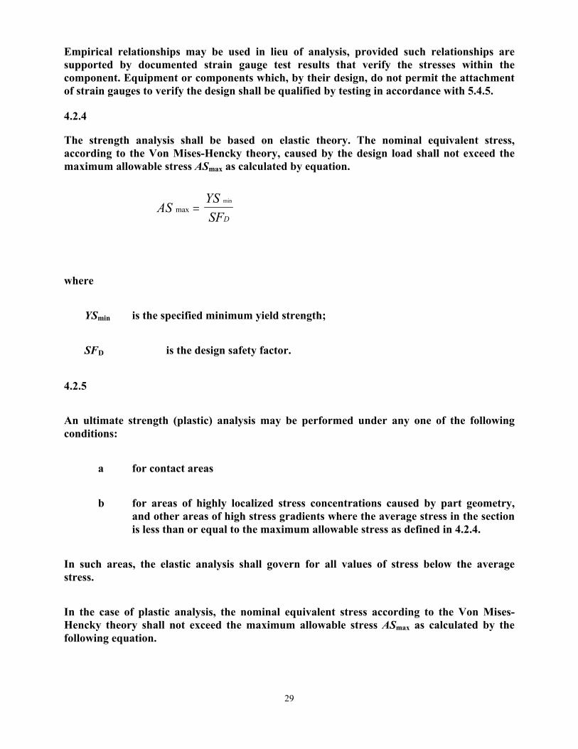
Empirical relationships may be used in lieu of analysis, provided such relationships are supported by documented strain gauge test results that verify the stresses within the component. Equipment or components which, by their design, do not permit the attachment of strain gauges to verify the design shall be qualified by testing in accordance with 5.4.5.
4.2.4
The strength analysis shall be based on elastic theory. The nominal equivalent stress, according to the Von Mises-Hencky theory, caused by the design load shall not exceed the maximum allowable stress ASmax as calculated by equation.
where
YSmin is the specified minimum yield strength;
SFD is the design safety factor.
4.2.5
An ultimate strength (plastic) analysis may be performed under any one of the following conditions:
a for contact areas
b for areas of highly localized stress concentrations caused by part geometry, and other areas of high stress gradients where the average stress in the section is less than or equal to the maximum allowable stress as defined in 4.2.4.
In such areas, the elastic analysis shall govern for all values of stress below the average stress.
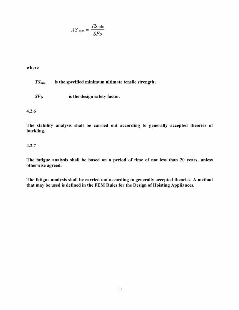
In the case of plastic analysis, the nominal equivalent stress according to the Von Mises-Hencky theory shall not exceed the maximum allowable stress ASmax as calculated by the following equation.
ASYSSFD
maxmin
=
30
where
TSmin is the specified minimum ultimate tensile strength;
SFD is the design safety factor.
4.2.6
The stability analysis shall be carried out according to generally accepted theories of buckling.
4.2.7
The fatigue analysis shall be based on a period of time of not less than 20 years, unless otherwise agreed.
The fatigue analysis shall be carried out according to generally accepted theories. A method that may be used is defined in the FEM Rules for the Design of Hoisting Appliances.
ASTSSFD
maxmin
=
31
Minutes Of API C3/SC7/TG4
Drill Stem Elements & Compounds Jack Smith, Task Group Chairman
Jack Smith, Secretary June 26, 2001 Hyatt Regency Hotel, Calgary, Alberta, Canada
Meeting called to order at 1:20 pm. An attendance roster was passed around room. 1.83 Review of RP7A1 Herschel McDonald reported that testing with the new equipment and new test sample is on-going with good results. He will attend the API Executive Committee on Standardization Research Program Review meeting at 3:00 pm today to answer questions regarding future funding for testing. The expected timetable for rewriting API RP7A1 is as follows:
• The formulation for a new reference compound that does not contain lead will be defined between now and end of this calendar year.
• Testing will be completed this calendar year.
• Rewrite will begin after first of next calendar year.
1.104: Dynamic Loading of Drill Pipe Brett Chandler reported on the activities of the work group. John Altermann retired from Transocean Sedco Forex and has stepped down as chairman of this work group. Brett Chandler with Grant Prideco will assume the role of chairman. Brett acknowledged the work and contributions of John in this and other API work groups. Brett restated the charge of the work group which is to rewrite Section 8 of API RP7G to address fatigue and dynamic loading of drill pipe and other drill stem elements. This work will include
• Removing all non-fatigue related elements from Section 8 and putting them somewhere else in the document.
• Review conflicting fatigue data in RP7G originally submitted by Arthur Lubinski and Youngstown Steel. Choose which is the more correct data based on literature, data and test results available at this time. No new tests will be conducted to verify what is presently in RP7G.
It is intended that this work will be applicable to ISO 10407-1 Petroleum and natural gas industries — Drilling and production equipment — Part 1: Drill stem design and operating limits Brett reported on a meeting held in Calgary June 26, 2001.
• Ed Bailey will review the RP7G Lubinski and Youngstown data.
• Ed Bailey will provide guidelines for fatigue tests to determine the endurance limit of a drill string component and guidelines for fatigue tests to compare the fatigue characteristics of one component to another.

32
• Tony Collins will merge sections 8.3, 11.5 and 11.6 of RP7G and add an explanation of cumulative fatigue damage.
• J. P. Peter and Brett Chandler will submit ways to improve fatigue resistance of drill stem elements.
• ISO SC4 has submitted a new work item request for an ISO document that will cover full scale testing of drill stem elements.
A copy of the minutes of the meeting held in Calgary June 26, 2001 will be attached to the report of this meeting.
1.105: Tool Joint Tensile Yield at Recommended Make-up Torque Larry Williams reported on the progress of this work group. Since the meeting in Fort Worth in February, 2001, this work group has revised the text and figures being proposed. Larry handed out copies of the latest proposal for discussion. A copy of this proposal will be attached to the report of this meeting. Based on this proposal, the Task Group recommended the following changes to RP7G when the new material is added:
• Paragraph A7 will be Titled Tensile Yield Strength of Drill Pipe Body. In the work group’s latest proposal, the pipe portion of a drill pipe assembly was called a tube. Steve Williamson suggested using the ISO 11961 terminology and call the pipe portion drill pipe body.
• Paragraph A8 will be Torsional Yield Strength of Drill Pipe Body.
• The term Rotary Shouldered Connections will be removed from paragraphs A.8.1 and A.8.2.
• Paragraph A9 will be Torque Calculations of Rotary Shouldered Connections.
• Paragraph A10 will be Combined Torsion and Tension to yield Rotary Shouldered Connections and Drill Pipe Body.
The task group discussed the latest proposal and comments submitted to Larry earlier by John Casner. Larry will revise the proposal based on this discussion and submit to the Task Group at the next Winter meeting.
1.106 Drill String Identification Markings At the meeting in Fort Worth in February 2001, Tom Smith submitted a NWI to revise the tool joint pin base stenciling to include a new drill pipe weight code. It was moved, seconded, and passed in February that this marking scheme be added to the work done on Drill String Identification Markings and submitted for letter ballot. There was no additional report on this item. Status Reports of ISO Work Report on ISO 10407-1 Petroleum and natural gas industries — Drilling and production equipment — Part 1: Drill stem design and operating limits Ed Bailey reported that 10407-1 was submitted to ISO and rejected because of “should/shall” language and because of the American Standard units used.

33
Jim Hall reported that in the DIS version of ISO documents, commas must be used instead of periods in American Standard Units. Jim believes this is unacceptable and says the possible alternatives are
1) Not to submit API documents for conversion to ISO documents or 2) Do not include American Standard units in documents. When the ISO document is
released, adopt the Standard as a Regional Annex and remove all metric units and replace them with American Standard units.
Ed Bailey is not sure when the work on this document will be complete. Report on ISO 10407-2 Petroleum and natural gas industries — Drilling and production equipment — Part 2: Standard for inspection and classification of drill stem elements. Joe Mackin reported that work is ongoing and a draft should be submitted by the end of the year. Report on 10424-1 Petroleum and natural gas industries — Drilling and production equipment — Part 1: Specifications for rotary drill stem elements Doyle Brinegar distributed copies of his draft. He reported that he is ready to release as CD to ISO. Report on 10424-2 Petroleum and natural gas industries — Drilling and production equipment — Threading, gauging and testing of rotary shouldered thread connections Tony Collins reported that he is within 6 weeks of circulating a working draft. Report on 11961 Petroleum and natural gas industries — Drill pipe with weld-on tool joints — Specification Steve Williamson reported that a meeting was held Thursday and Friday of last week. Phil Jackman will process changes in the documents resulting from that meeting in about one month. Report on 11146 Petroleum and natural gas industries — Aluminum alloy drill pipe Brett Chandler reported that the US became involved in this standard at the DIS stage and has submitted a no vote and very large list of comments. Brett is concerned about the 2nd DIS because there is some resistance to acting on the comments submitted by the US. The US is perceived as being resistive but Brett feels as thought the US is adding value to the document. The next meeting will be in September in Russia.
New Business Steve Williamson has submitted a NWI to develop a procedure for breaking-in new tool joints during manufacturing. This procedure will be applicable to ISO 11961. Brett Chandler reported that the Errata for API documents are not being sent to document holders. Doyle Brinegar added that even when copies of Errata are specifically requested, it is difficult to get them. Jim Hall will look into this. Meeting was adjourned at 5:20.
34
A.8.3 Combined Torsion and Tension to Yield Rotary Shouldered Connection and Tube Combined Torsion and Tension to Yield Drill Pipe
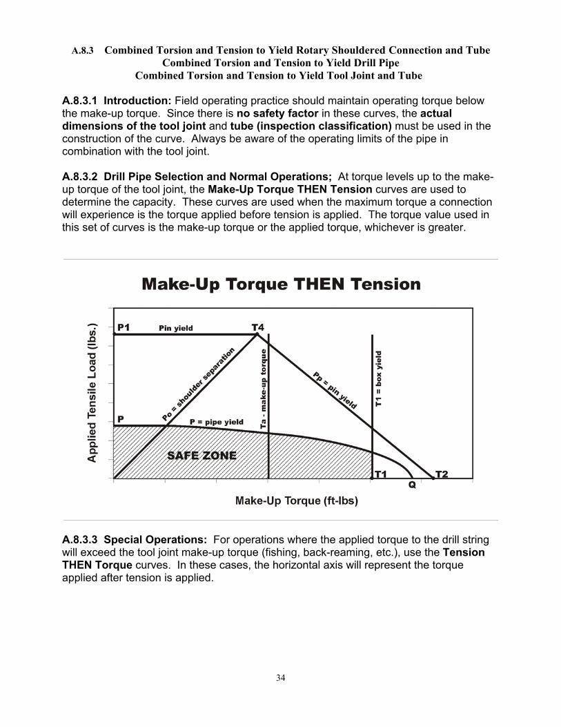
Combined Torsion and Tension to Yield Tool Joint and Tube A.8.3.1 Introduction: Field operating practice should maintain operating torque below the make-up torque. Since there is no safety factor in these curves, the actual dimensions of the tool joint and tube (inspection classification) must be used in the construction of the curve. Always be aware of the operating limits of the pipe in combination with the tool joint. A.8.3.2 Drill Pipe Selection and Normal Operations; At torque levels up to the make-up torque of the tool joint, the Make-Up Torque THEN Tension curves are used to determine the capacity. These curves are used when the maximum torque a connection will experience is the torque applied before tension is applied. The torque value used in this set of curves is the make-up torque or the applied torque, whichever is greater.
A.8.3.3 Special Operations: For operations where the applied torque to the drill string will exceed the tool joint make-up torque (fishing, back-reaming, etc.), use the Tension THEN Torque curves. In these cases, the horizontal axis will represent the torque applied after tension is applied.

35
A.8.3.4 Equation Definitions: The variables used in the equations below are defined in A.8.1.
pmAYP =1
( )
++
+=
fRfRpA
TAAP
st
b
apbo
θπ cos2
( )
++
−+=fRfRpA
TYAAPs
tp
ampbp
θπ cos2
++
= fRfRpAYT s
tb
m
θπ cos2121
++
= fRfRpAYT s
tp
m
θπ cos2122

36
+
=
θπ cos2123 fRpAYT t
pm
++
+
= fRfRp
AAAAYT s
t
bp
bpm
θπ cos2124
2
2
096167.0
⋅−=
JDQ
YAP tm
A description of the values calculated above and those used to plot the curves are: Ta = The torque that is applied to the tool joint before tension is applied, either the make-up torque or the operational torque, whichever is greater P1 = The tensile strength of the tool joint pin at ¾” from the make-up shoulder Po = The tension required to separate the tool joint shoulders after Ta is applied and is represented by the line from the origin to the point T4 Pp = The tension required to yield the pin after Ta is applied and is represented by the line from T2 line to either T4 or T3 T1 = The torsional strength of the box of the tool joint and is represented by a vertical line at that value on the x-axis T2 = The torsional strength of the pin of the tool joint T3 = The torsional load required to produce additional make-up of the connection when the shoulders are separated by an external tensile load on the pipe that produces yield stress in the tool joint pin T4 = The make-up torque at which pin yield and shoulder separation occur simultaneously with an externally applied tensile load P = The tensile capacity of the drill pipe tube in the presence of torsion represented by the elliptical curve. This equation was produced by rearranging the equation in Appendix A.9.2. A.8.3.5 Failure Modes: The failure modes under combined torsion/tension loads are: 1) pin yield, 2) box yield, 3) shoulder separation (and seal failure), 4) tube yield. A.8.3.6 Using the Curves: Calculate the above values using the actual dimensions of the tool joints and tube. Use these values to plot a working curve. Problem 1 Drilling an Extended Reach Well Assume:

37
Maximum Drill Torque = 30,000 ft-lbs
Drill pipe string is 5”, 19.50 ppf, Grade S, Premium Class with NC50 tool joints (6-5/8” OD
x 2-3/4” ID) Calculated values: P = 560,764 lbs Ta (make-up torque) = 38,036ft-lbs P1 = 1,532,498 lbs T1 = 63,657 ft-lbs T2 = 63,393 ft-lbs T4 = 31,762 ft-lbs Question 1 Is the drill pipe string adequate for the anticipated torque? {{Yes}} 2 What is the allowable hook load? {{P = 480,266 lbs at 30,000 ft-lbs}}
Problem 2 Fishing Drill Pipe String in Problem 1 Question: 1 What is the maximum pull before failure without torque? {{With a straight pull and no torque, the maximum pull is the tensile capacity of the tube which is P=560,764 lbs.}}
Problem 3 Back-Reaming Hole with Drill Pipe Stinger Assume: Maximum Reaming Torque = 15,000 ft-lbs
38
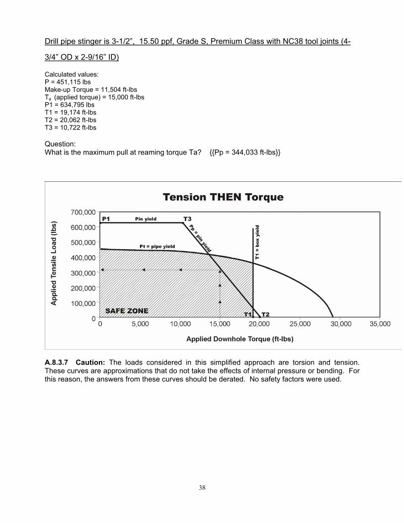
Drill pipe stinger is 3-1/2”, 15.50 ppf, Grade S, Premium Class with NC38 tool joints (4-
3/4” OD x 2-9/16” ID) Calculated values: P = 451,115 lbs Make-up Torque = 11,504 ft-lbs Ta (applied torque) = 15,000 ft-lbs P1 = 634,795 lbs T1 = 19,174 ft-lbs T2 = 20,062 ft-lbs T3 = 10,722 ft-lbs Question: What is the maximum pull at reaming torque Ta? {{Pp = 344,033 ft-lbs}}
A.8.3.7 Caution: The loads considered in this simplified approach are torsion and tension. These curves are approximations that do not take the effects of internal pressure or bending. For this reason, the answers from these curves should be derated. No safety factors were used.

39
TG4/RG1 Resource Group on Threading and Gauging
Report of Status of ISO document. Proposed to add information on connections beyond those now in the body of spec 7 After considerable discussion, the current proposal is to include two tables: Preferred threads (NC, Reg, FH and IF’s recast as NC), and non-preferred threads for standardization (H90, SL H90, PAC and a request for OH). We have information on GOST threads, which fall in the Preferred range, except for two, which are much like regular connections.
Gauge and Quality Issues Andy Radford reported that funding is probable to restore and replace the Grand Master gauges they need it. This makes it reasonable to plan to implement the other resolutions from Los Angeles. The working group plans to resume activity in the fall. NIST has provided a report on the current standoff of the Grands, and a spreadsheet (following) of the current certification status of the Regional Masters. There is strong feeling that this should be posted on the API web site, so that owners of Reference masters can verify their calibration chain. Posting will also allow any errors to be notified to NIST for correction. Discussion continued on how to make it practical to maintain an auditable calibration chain down to the working gauge level. This will continue at the next meeting, in Houston around the end of September.

40
TYPE API# 2001NC26 4401 0.6247NC31 4402 0.6245NC35 7000 0.6244NC38 4403 0.6250NC40 3005 0.6235NC44 7001 0.6259NC46 4404 0.6248NC50 4405 0.6248NC56 7002 0.6246NC61 7003 0.6250NC70 7004 0.62492 3/8" Reg 1101 0.62402 7/8" Reg 1102 0.62443 1/2" Reg 1103 0.62514 1/2" Reg 1104 0.62545 1/2" Reg 1105 0.62506 5/8" Reg 1700 0.62447 5/8" Reg 1142 0.62538 5/8" Reg 1701 0.62512 3/8" Reg LH 1751 0.62532 7/8" Reg LH 1752 0.62513 1/2" Reg LH 1753 0.62504 1/2" Reg LH 1754 0.62445 1/2" Reg LH 1755 0.62426 5/8" Reg LH 1756 0.62407 5/8" Reg LH 1779 0.62558 5/8" Reg LH 1757 0.62483 1/2" FH 3001 0.62514 1/2" FH 3002 0.62575 1/2" FH 3003 0.62436 5/8" FH 3004 0.62445 1/2" IF 4406 0.6246
Current certification status of the Regional Master Gauges.

Appendix A
Attendance Rosters


Appendix B New Work Items

Page 1 of 2 API Exploration & Production (E&P) Standards Committee NEW WORK ITEM (NWI) PROPOSAL FORM Type or legibly print all information requested on the form. Failure to provide all information requested may result in rejection or delayed consideration. Submit the form to the applicable API standards subcommittee if known, or to: API E&P Department, 1220 L Street, NW, Washington, DC 20005. Consult Subcommittee Chair, Secretary or API Staff if uncertain of information for this block.
NWI Proposal Number: SC701-1 (unique identifying number); API Subcommittee 7 ; API Committee 3
Category of Standard: A, API/ISO X ; B,ISO only ; C, API only (Ref. API S1,¶ 5.2.1.4)
Sales History: (API staff enter sales data for affected or similar API standard as indication of industry usage.)
Related ISO Standard Number, Title and Date: ISO DIS 14693 Is the proposed work on ISO work plan? Y ;Is ISO project active? Y ; ISO SC and WG number: TG67/SC4/WG1 ISO Stage Number DIS ; ISO Project Leader Mark Sibille
Title of Proposal: Modify Spec 7K - Sections: 4; 5.4.2; 5.4.5; 7.9.3; 8.4.6.3.1
Affected API Standard: New Standard? Revision? (If a revision, fully identify current standard.) Title: API Specification 7K Specification for Drilling Equipment Edition: 2 Effective Date: 2/96 Date & Number of Supplement(s):
Relationship to any other standards: a. List related or existing API, ISO or other SDO’s standard: API Spec 8C ISO 13535 b. Identify and justify any potential duplication of this work with above standards: NONE KNOWN
Work Description and Justification: (Describe scope of new standard or specific revisions proposed for an existing standard. Justify this work by identifying its value to industry. Be specific; use attachment if needed.) Modify Section 4 of Spec 7K to agree with corresponding section of 8C regarding plastic analysis and stress distribution. Modify Section 5.4.5 Alternate Design Verification Test Procedure and Rating, to apply to tongs and other equipment to ensure that the procedure meets the intent of Section 4. Modify Section 5.4.2 to clarify application of this section to manual tongs. Modify Section 7.9.3 (editorial change) to clarify intent. Modify Section 8.4.6.3.1 to include areas of low stress for MPI inspection.
Proposed Project Leader: (Include: Name, Company, Mailing and Street (if different) Address, Telephone , FAX numbers (with country dialing code) and qualification to lead this work. This person will be accountable for the quality and timeliness of the work.) NOTE: Committees cannot consider NWI proposals unless this section is complete. Larry Foley Foley Drilling Tools P.O. Box 81007 203 Beau Pre Rd Lafayette, LA 70598 Phone 337-232-4400 FAX 337-237-9406 email: [email protected] Member SC7/TG3

NWI Form, Page 2 of 2
Resource Requirements: a. Number of task group or work group members needed: 4 (must include at least two user participants) b. Names of volunteers for this work (attach roster if proposing assignment to an existing task group or work group): Larry Foley Foley Drilling Tools Bob DePont Varco c. Expected number of meetings 0 d. Total member meeting days (a times c) 0 e. Describe any unusual resource requirements: None – draft by email and present for approval at June conference.
Milestone Target Dates Date Comments
Assumed start date (After approved and assigned to Work Group (WG) or Task Group (TG))
5/01
Working Draft agreed by TG to proceed to Subcommittee (SC) (ISO Stage 20.99)
6/01 June Standards Conference
Draft approved by SC for formal ballot (ISO Stage 30.99)
6/01 June Standards Conference
Publication of Standard (ISO Stage 60.60)
12/01
Indicate significance to this proposal of following considerations by entering numerical ratings as follows: 1 = Very Low/No; 2 = Low; 3 = Medium; 4 = High; 5 = Very High/Yes. Provide a brief explanation in the space provided.
Information Area Rating Explanation/Supporting Data
Government or Regulatory Pressure? (If YES, state source/code)
1
Particular Environmental, Safety, and/or Health aspects? (If YES, state what)
4 Current wording of specification does not require testing to meet the intent of the specification.
Document affects user’s Capital Expenditures? (If YES, provide supporting information)
2
Document affects user’s Operating Expenditures? (If YES, provide supporting information)
1
Is there widespread industry need for document? (If YES, provide supporting information)
5
Is the applicable knowledge developed and available for this work? (If YES, state where)
5
Total Rating 18
Is the equipment, process or design considered non-proprietary (not patented)? Yes X No Proposal submitted by: Name: Larry Foley Company: Foley Drilling Tools Phone Number: 337-232-4400 Date Submitted: 4/26/01 Submitted on behalf of: SC7/TG3

Page 1 of 2 API Exploration & Production (E&P) Standards Committee NEW WORK ITEM (NWI) PROPOSAL FORM Type or legibly print all information requested on the form. Failure to provide all information requested may result in rejection or delayed consideration. Submit the form to the applicable API standards subcommittee if known, or to: API E&P Department, 1220 L Street, NW, Washington, DC 20005. Consult Subcommittee Chair, Secretary or API Staff if uncertain of information for this block.
NWI Proposal Number: SC701-2 (unique identifying number); API Subcommittee 7 ; API Committee 3
Category of Standard: A, API/ISO X ; B,ISO only ; C, API only (Ref. API S1,¶ 5.2.1.4)
Sales History: (API staff enter sales data for affected or similar API standard as indication of industry usage.)
Related ISO Standard Number, Title and Date: ISO DIS 14693 Is the proposed work on ISO work plan? Y ;Is ISO project active? Y ; ISO SC and WG number: TG67/SC4/WG1 ISO Stage Number DIS ; ISO Project Leader Mark Sibille
Title of Proposal: Modify Spec 7K - Section 8.4.6: NDE of Coating
Affected API Standard: New Standard? Revision? X (If a revision, fully identify current standard.) Title: API Specification 7K Specification for Drilling Equipment Edition: 2 Effective Date: 2/96 Date & Number of Supplement(s):
Relationship to any other standards: a. List related or existing API, ISO or other SDO’s standard: API Spec 8-C ISO 13535 b. Identify and justify any potential duplication of this work with above standards: NONE KNOWN
Work Description and Justification: (Describe scope of new standard or specific revisions proposed for an existing standard. Justify this work by identifying its value to industry. Be specific; use attachment if needed.) Modify Section 8.4.6 to allow NDE to be performed of coating. Tests will be performed at the expense of Foley Drilling Tools. Other applicable specifications will be reviewed. Summary of findings and proposed text will be presented to the TG at the June Standards Conference for discussion. This project was proposed by the TG last year.
Proposed Project Leader: (Include: Name, Company, Mailing and Street (if different) Address, Telephone , FAX numbers (with country dialing code) and qualification to lead this work. This person will be accountable for the quality and timeliness of the work.) NOTE: Committees cannot consider NWI proposals unless this section is complete. Larry Foley Foley Drilling Tools P.O. Box 81007 203 Beau Pre Rd Lafayette, LA 70598 Phone 337-232-4400 FAX 337-237-9406 email [email protected] Member SC7/TG3

NWI Form, Page 2 of 2
Resource Requirements: a. Number of task group or work group members needed: 2 (must include at least two user participants) b. Names of volunteers for this work (attach roster if proposing assignment to an existing task group or work group): Larry Foley Foley Drilling Tools Tom Becker Varco c. Expected number of meetings 0 d. Total member meeting days (a times c) 0 e. Describe any unusual resource requirements: None – draft by email and present for approval at June conference.
Milestone Target Dates Date Comments
Assumed start date (After approved and assigned to Work Group (WG) or Task Group (TG))
5/01
Working Draft agreed by TG to proceed to Subcommittee (SC) (ISO Stage 20.99)
6/01 June Standards Conference
Draft approved by SC for formal ballot (ISO Stage 30.99)
6/01 June Standards Conference
Publication of Standard (ISO Stage 60.60)
12/01
Indicate significance to this proposal of following considerations by entering numerical ratings as follows: 1 = Very Low/No; 2 = Low; 3 = Medium; 4 = High; 5 = Very High/Yes. Provide a brief explanation in the space provided.
Information Area Rating Explanation/Supporting Data
Government or Regulatory Pressure? (If YES, state source/code)
1
Particular Environmental, Safety, and/or Health aspects? (If YES, state what)
4 Method using contrasting background improves the sensitivity of NDE
Document affects user’s Capital Expenditures? (If YES, provide supporting information)
1
Document affects user’s Operating Expenditures? (If YES, provide supporting information)
1
Is there widespread industry need for document? (If YES, provide supporting information)
5 Improvement of quality of NDE
Is the applicable knowledge developed and available for this work? (If YES, state where)
5
Total Rating 18
Is the equipment, process or design considered non-proprietary (not patented)? Yes X No Proposal submitted by: Name: Larry Foley Company: Foley Drilling Tools Phone Number: 337-232-4400 Date Submitted: 4/26/01 Submitted on behalf of: SC7/TG3