Embed Size (px)
Citation preview
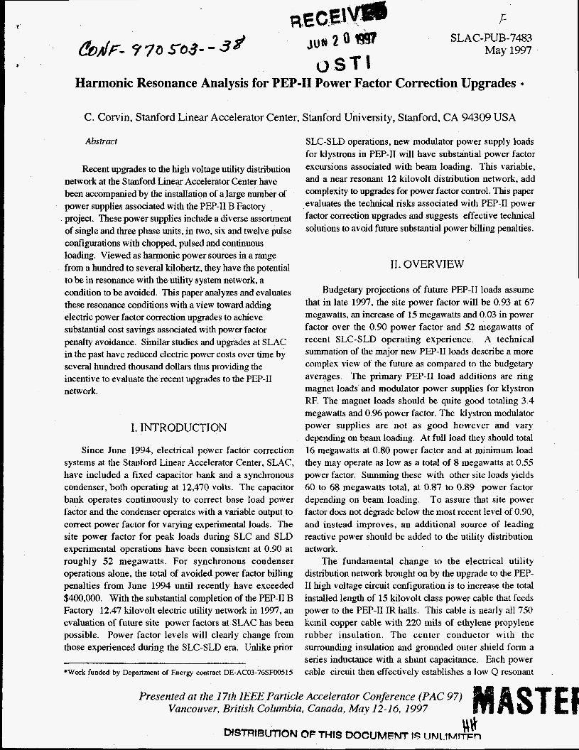
F SLAC-PUB-7483
May 1997
Harmonic Resonance Analysis for PEP-I1 Power Factor Correction Upgrades *
C. Corvin, Stanford Linear Accelerator Center, Stanford University, Stanford, CA 94309 USA
Abstract
Recent upgrades to the high voltage utility distribution network at the Stanford Linear Accelerator Center have been accompanied by the installation of a large number of power supplies associated with the PEP-I1 B Factory project. These power supplies include a diverse assortment of single and three phase units, in two, six and twelve pulse configurations with chopped, pulsed and continuous loading. Viewed as harmonic power sources in a range from a hundred to several kilohertz, they have the potential to be in resonance with the utility system network, a condition to be avoided. This paper analyzes and evaluates these resonance conditions with a view toward adding electric power factor correction upgrades to achieve substantial cost savings associated with power factor penalty avoidance. Similar studies and upgrades at SLAC in the past have reduced electric power costs over time by several hundred thousand dollars thus providing the incentive to evaluate the recent upgrades to tlie PEP-I1 network.
I. INTRODUCTION
Since June 1994, electrical power factor correction systems at the Stanford Linear Accelerator Center, SLAC, have included a fixed capacitor bank and a synchronous condenser, both operating at 12,470 volts. The capacitor bank operates continuously to correct base load power factor and the condenser operates with a variable output to correct power factor for varying experimental loads. The site power factor for peak loads during SLC and SLD experimental operations have been consistent at 0.90 at roughly 52 megawatts. For synchronous condenser operations alone, the total of avoided power factor billing penalties from June 1994 until recently have exceeded $400,O00. With the substantial completion of the PEP-I1 B Factory 12.47 kilovolt electric utility network in 1997, an evaluation of future site power factors at SLAC has been possible. Power factor levels will clearly change froin those experienced during the SLC-SLD era. Unlike pnor
*Work funded by Department of Energy contract DE-AC03-76SF00515
SLC-SLD operations, new modulator power supply loads for klystrons in PEP-I1 will have substantial power factor excursions associated with beam loading. This variable, and a near resonant 12 kilovolt distribution network, add complexity to upgrades for power factor control. This paper evaluates the technical risks associated with PEP-I1 power factor correction upgrades and suggests effective technical solutions to avoid future substantial power billing penalties.
11. OVERVIEW
Budgetary projections of future PEP-I1 loads assume that in late 1997, the site power factor will be 0.93 at 67 megawatts, an increase of 15 megawatts and 0.03 in power factor over the 0.90 power factor and 52 megawatts of recent SLC-SLD operating experience. A technical summation of the major new PEP-I1 loads describe a more complex view of the future as compared to the budgetary averages. The primary PEP-I1 load additions are ring magnet loads and modulator power supplies for klystron RF. The magnet loads should be quite good totaling 3.4 megawatts and 0.96 power factor. The klystron modulator power supplies are not as good however and vary depending on beam loading. At full load they should total 16 megawatts at 0.80 power factor and at minimum load they may operate as low as a total of 8 megawatts at 0.55 power factor. Summing these with other site loads yields 60 to 68 megawatts total, at 0.87 to 0.89 power factor depending on beam loading. To assure that site power factor does not degrade below the most recent level of 0.90, and instead improves, an additional source of leading reactive power should be added to the utility distribution network.
The fundamental change to the electrical utility distribution network brought on by the upgrade to the PEP- I1 high voltage circuit configuration is to increase the total installed length of 15 kilovolt class power cable that feeds power to the PEP-I1 IR halls. This cable is nearly all 750 kcmil copper cable with 220 mils of ethylene propylene rubber insulation. The center conductor with the surrounding insulation and grounded outer shield form a series inductance with a shunt capacitance. Each power cable circuit then effectively establishes a low Q resonant
ST Presented at the 17th IEEE Particle Accelerator Coilference (PAC 97) Vancouver, British Columbia, Canada, May 12-16, 1997

DISCLAIMER
This report was prepared as an account of work sponsored by an agency of the United States Government. Neither the United States Government nor any agency thereof, nor any of their employees, make any warranty, express or implied, or assumes any legal liabili- ty or responsibility for the accuracy, completeness, or usefulness of any information, appa- ratus, product, or process disclosed, or represents that its use would not infringe privately owned rights. Reference herein to any specific commercial product, process, or service by trade name, trademark, manufacturer, or otherwise does not necessan’ly constitute or imply its endorsement, recommendation, or favoring by the United States Government or any agency thereof. The views and opinions of authors expressed herein do not necessar- ily state or reflect those of the United States Government or any agency thereof.
Portions of this documeat may be illegible in electronic image products. Images are p;raduced h m the best available original document.

transmission circuit. In general, industrial power circuits such as these are either too short or too long to create a resonant condition that would be of concern. The new PEP-I1 circuits however are somewhere in between. The effect of increasing power to the PEP IR halls and adding miles of new cable has been to lower the circuit resonant frequencies substantially. Shunt capacitors added to the PEP-I1 network can not only improve power factor but be used to shift otherwise harmful resonant conditions to more benign frequencies. The goal of this first study has been to identify the areas of risk and the best locations for the addition of shunt capacitors at 12.47 kilovolts.
A complete engineering solution for power factor correction during PEP-I1 operations is not within the scope of this paper but is the logical next step. It would of necessity include attention to switching transient response, grounding, voltage regulation, and insulation coordination as well as the control scheme(s) for site power factor management.
111. TECHNICAL
The PEP-I1 electrical utility network consists of four high voltage circuits each operating at a nominal voltage of 12.47 kilovolts and radiating out of the SLAC master substation to the various PEP-I1 IR halls. Each of the circuits is a combination of series and parallel cable runs that total almost 8 miles of installed cable plant. The electrical circuit lengths are substantially greater than the physical routes of the right of ways which are almost entirely in underground cable duct banks. Per unit circuit constants used to model the cable network are typical for standard cables, and are: 0.038 ohms inductive reactance per 1000 feet at 60 hertz, 0.0171 ohms resistance per IO00 feet at 60 hertz, and 416.6 ohms capacitive reactance per 1000 feet at 60 hertz. These values are typical for the 133 percent MV-90 design cable in use. The dielectric constant of the cable insulation varies by manufacturer and the date of manufacture (age). It is between 2.7 and 3.0. The XIR ratio is about 2.2 . For the preliminary results included here, mutual inductive reactance has been left out. As of the date of this paper some sections of cable plant are yet to be connected, with some being parallel and electrically floating, and some being long stubs, connected at only one end
The PEP-I1 hannonic power sources supplied by the utility feeders are power supplies located at the IR halls. By origin, 2nd order harmonics (of a 60 hertz fundamental) are produced by small single phase supplies
SLAC-PUB-7483 May 1997
but are often modest in magnitude. Single phase supplies in three phase groupings often sum to cancel most second harmonic content through one or more upstream delta-wye transformations. The triplen 3rd and 9th order harmonics appear in unbalanced supplies of any type. This three-nine signature is useful for locating faulty power supply - regulator controls and thyristor trigger circuits. The 5th and 7th order harmonics appear in six pulse power supplies and the 11th and 13th orders dominate in 12 pulse power supplies. Higher order harmonics are also generated but are of lesser magnitude. For other frequencies, modulation of the power system power feeder circuits can occur at the chop, pulse and repetition rate frequency needed to supply their respective loads. PEP-I1 magnet power supplies are planned to chop at 20,000 hertz. Listing these harmonic sources gives orders of 2, 3, 5, 7, 11 and 13, plus 333. Since the addition of shunt power factor capacitors will lower resonant frequencies, the 4th and 8th orders, 240 hertz and 480 hertz respectively, are the lowest desirable frequencies of interest for power factor correction resonance as they avoid the source frequencies above. The addition of capacitors might seek to drive the final operating circuit resonant frequency center point there, or close to it, ideally 240 hertz if possible . The possible installation of 60 hertz inductors along with power factor capacitors is not considered here in that it does not consider the circuit impedances and resonances already installed and it adds unnecessary cost.
The ideal location of power factor capacitors is usually recommended to be between one-third and one-forth of the total length of a distribution circuit taken from the circuit load end. This generally manages and distributes the voltage rise associated with pulling leading reactive power through lagging inductive cable circuit impedances. As the four PEP-I1 circuits are not accessible along their complete length some alternative location may have to be considered including placement at the circuit ends , at a PEP-I1 IR hall.
IV. RESONANT UTILITY CIRCUITS
As the utility network must at times be operationally switched, no single model is really correct for all conditions. Various configurations of cable circuit impedances are possible, however those models that combine to produce the lowest frequencies are of the most interest. Summations that maximize shunt capacitance and series inductance are listed in Table 1, below. For reference, the frequencies of the nearest hannonics, (2)
Presented at the 17th IEEE Particle Accelerator Conference (PAC 97) Vancouver, British Columbia, Canada, May 12-16, 1997

SLAC-PUB-7483 May 1997
the 9th, 10th and 11th orders, are also listed in bold type.
Of first concern are IR-2 and IR-4 which bracket the 1 lth harmonic at 660 hertz and are resonant at 698 and 602 hertz respectively. Power factor correcting capacitors should be considered for those locations to shift resonance to a lower frequency. Of less concern are IR-10 and IR-6 which bracket the 9th harmonic of 540 hertz, at 501 and 551 hertz respectively. As the triplen ninth harmonic only appears as a source under abnormal unbalanced conditioiis, IRs ten and six would not be primary locations for power factor capacitors. Shifting these circuit resonances as low as 240 hertz would require a sizable installation of capacitors. However a large installation may be both technically indicated and also the cost effective solution.
PEP-II Locations, Harmonic Orders
IR-10 9th Harmonic IR-6 B-750, SLD-SLC IR- 12 10th Harmonic
11th Harmonic IR-4
IR-2 IR-8
Net Circuit Len,& (ft)
12585
11440 11040 1 lo00
10480
9040 5365
Resonant Frequency (Hz)
50 1 540 55 1 57 1 573 600 602 660 698
1176
Table 1: Lowest possible resonance frequency of PEP-I1 12.47 kilovolt utility supply circuits with selected power supply harmonic sources shown in bold type.
V. AVOIDED POWER PENALTIES
Monthly power factor penalties are incurred at SLAC based on power factor and peak megawatt demand. The current maximum contracted rate of delivery, CRD, is limited to 53.903 megawatts [l] . PEP-I1 operations will exceed this maximum. Penalties will be set as power factor varies at peak demand above 53.9 megawatts. Table 2 describes the potential magnitude of these penalties.
Demand $ Max Penalty Power (mw) per month Factor
60.0 $32,342 0.87
68.0 $ 0 0.95+ 68.0 $24,795 0.89
Table 2: Possible maximum SLAC power factor penalties for PEP-I1 operations.
The quantity of new additional leading reactive power needed for PEP-I1 varies from a minimum of 3.5 megavars to maintain 0.90 power factor, to 11 .O megavars to achieve 0.95 power factor. A simple per-unit cost for capacitors in this quantity, neglecting switching, transient suppression, and site related costs, is estimated at 7 cents per volt- ampere reactive. The most aggressive proposal for power factor improvement would then be 0.95 power factor at a capacitor (only) cost of $770,000. Simple payback from avoided penalties considering the costs of other equipment and related project costs would be less than 5 years. The penalty for not correcting power factor at all would run about $200,000 a year for eight months of annual PEP-I1 operations at peak demand.
VI. SUMMARY
PEP-I1 high voltage power distribution circuits are configured to present a potential resonant condition with non-linear PEP-I1 loads. Power factor capacitors can reduce the risk of an undesirable resonant condition and also reduce PEP-I1 operating costs for electric power. A project for a PEP-I1 power factor upgrade is indicated at a cost of about $ 1,000,000 with a simple return on investment of about 5 years.
VII. REFERENCES
[ l ] Western Area Power Administration, Cerrtral Valley Project Notice of Rate Order No. WAPA-59 (July 2, 1993). Federal Register, vol. 58, no. 126, pp. 3594S35949.
Presented at the 17th IEEE Particle Acceleralor Coigerence (PAC 97) Vancouver, British Columbia, Canada, May 12-1 6, 1997