Embed Size (px)
Citation preview

No
rth W
est Hu
tton
Decom
missioning Program
me
January 2005
BP External Affairs DepartmentFarburn Industrial Estate,Dyce, Aberdeen AB21 7PB
Tel +44 (0)1224 832000
www.bp.com/northwesthutton February 2005
North West HuttonDecommissioningProgramme

CONTENTS LIST
Glossary of terms x
Section 1 INTRODUCTION 1
1.1 North West Hutton Decommissioning Programmes 2
Section 2 EXECUTIVE SUMMARY 5
2.1 Introduction and Recommendations 5
2.2 Background Information 82.2.1 Environmental Setting 82.2.2 Facilities to be Decommissioned 8
2.3 Principles Used to Assess Decommissioning Activity 102.3.1 Introduction 102.3.2 Legal Requirements 102.3.3 Methodology and Evaluation Process 11
2.4 Assessment of Decommissioning Options 132.4.1 Alternative Use and Re-use 132.4.2 Topsides Decommissioning 132.4.3 Jacket Decommissioning 142.4.4 Drill Cuttings Pile 182.4.5 Pipeline Decommissioning – PL 147 and PL 148 19
2.5 Interested Parties Consultation 21
2.6 Debris Clearance and Site Monitoring 21
2.7 Onshore Treatment and Disposal of Materials 21
2.8 Cost Summary and Schedule 22
2.9 Legacy 22
Section 3 BACKGROUND INFORMATION 23
3.1 Introduction 23
3.2 Layout of the Facilities in this Programme 23
3.3 Adjacent Facilities 24
3.4 Physical, Meteorological and Oceanographic Conditions 25
3.5 Fishing and Commercial Activities 263.5.1 Fishing 263.5.2 Commercial Activities 27
3.6 Ecology 273.6.1 Plankton and Primary Production 273.6.2 Seabed Communities 273.6.3 Fish and Shellfish 283.6.4 Marine Mammals 293.6.5 Seabirds 29
3.7 Conservation Status 333.7.1 Introduction 333.7.2 Annex I Habitats 333.7.3 Annex II Species 33
3.8 Onshore Sites for Dismantling and Treatment 34
References 36
Contents List
North West Hutton Decommissioning Programme February 2005 i

Section 4 DESCRIPTION OF ITEMS TO BE DECOMMISSIONED 37
4.1 Introduction 37
4.2 Description of the North West Hutton Platform 374.2.1 Support Structure 374.2.2 Topsides 41
4.3 Description of the North West Hutton Drilling Template and Wells 43
4.4 Description of the North West Hutton Pipelines 434.4.1 10” Natural Gas Export / Import Pipeline (PL174) 444.4.2 20” Oil Pipeline (PL148) 45
4.5 Description of the North West Hutton Drill Cuttings Pile 47
4.6 Debris and Other Material 49
References 50
Section 5 INVENTORY OF MATERIALS 51
5.1 Introduction 51
5.2 Topsides 51
5.3 Support Structures 525.3.1 Grout Densitometers 53
5.4 Well Related Material 53
5.5 Pipelines 53
5.6 Drill Cuttings Pile 54
5.7 Debris and Other Seabed Items 54
5.8 Onshore Treatment and Disposal of Materials 54
References 55
Section 6 GUIDING PRINCIPLES AND SCREENING PROCESS 57
6.1 Introduction 57
6.2 Guiding Principles 57
6.3 Assessment Methodology 58
6.4 Comparative Assessment Criteria 596.4.1 Safety 596.4.2 Environmental Impact 606.4.3 Social Impact 606.4.4 Technical Feasibility 616.4.5 Costs and Financial Management 61
6.5 Method for High Level Option Selection 62
6.6 Results of High Level Option Selection 626.6.1 Reuse of Installation 626.6.2 Decommissioning the Platform 636.6.4 Drill Cuttings 646.6.5 Pipelines 65
References 65
Contents List
North West Hutton Decommissioning Programme February 2005ii

Section 7 TOPSIDES DECOMMISSIONING 67
7.1 Introduction 67
7.2 Description of Possible Removal Methods 687.2.1 Offshore Deconstruction 687.2.2 Reverse Installation 697.2.3 Single Lift 71
7.3 Selection of Removal Method 717.3.1 Introduction 717.3.2 Assessment of Three Removal Methods 727.3.3 Comparison of Removal Methods 73
7.4 Reverse Installation Programme for Decommissioning the Topsides 737.4.1 Decommissioning of Wells and Removal of Conductors 737.4.2 Preparatory Work for Topsides Removal 747.4.3 Lifting and Transportation to Shore 757.4.4 Receiving and Dismantling Onshore 75
References 76
Section 8 JACKET DECOMMISSIONING 77
8.1 Introduction and Background 77
8.2 Present Condition of Jacket 77
8.3 Assessment of Jacket Removal Options 798.3.1 Introduction 798.3.2 Summary and Screening of Removal Techniques 80
8.4 Assessment of Jacket Removal by Offshore Deconstruction 818.4.1 Introduction 818.4.2 Jacket Removal Overview 81
8.5 Comparative Assessment of Jacket Removal Options 818.5.1 Introduction 81
8.6 Assessment of the Option of Full Jacket Removal 838.6.1 Technical Description of Removal Operations 838.6.2 Technical Assessment of Full Jacket Removal 858.6.3 Safety Evaluation of Full Jacket Removal 888.6.4 Environmental Impacts of Full Jacket Removal 908.6.5 Societal Impacts of Full Jacket Removal 908.6.6 Summary of Full Jacket Removal 91
8.7 Assessment of Option of Partial Removal of the Footings 918.7.1 Technical Evaluation of Partial Removal of the Footings 918.7.2 Safety Evaluation of Partial Removal of the Footings 938.7.3 Environmental Impacts of Partial Removal of the Footings 938.7.4 Societal Impacts of Partial Removal of the Footings 948.7.5 Summary of Partial Removal of the Footings 94
8.8 Assessment of the Option of Jacket Removal to the Top of the Footings 948.8.1 Technical Evaluation of Removal of the Jacket to the Top of the Footings 958.8.2 Safety Evaluation of Removal of the Jacket to the Top of the Footings 958.8.3 Environmental Impacts of Removal of the Jacket to the Top of the Footings 958.8.4 Societal Impacts of Removal of the Jacket to the Top of the Footings 958.8.5 Summary of Removal of the Jacket to the Top of the Footings 96
8.9 Cost Assessment 96
8.10 Comparative Assessment and Conclusions of Jacket Removal Evaluations 96
8.11 Recommended Decommissioning Option for the Jacket 98
References 99
Contents List
North West Hutton Decommissioning Programme February 2005 iii

Section 9 DRILL CUTTINGS 101
9.1 Introduction 101
9.2 Present Composition, Condition and Effects of the North West Hutton Drill Cuttings Pile 101
9.2.1 Introduction 1019.2.2 History 1019.2.3 Composition 1039.2.4 Physical Nature of the Drill Cuttings Pile 1039.2.5 Understanding of the North West Hutton Drill Cuttings Pile
and the Surrounding Area 104
9.3 Assessment of Decommissioning Options for the Drill Cuttings Pile 106
9.4 Option ‘Leave in-situ to degrade naturally’ 1079.4.1 Description 1079.4.2 Technical Feasibility 1079.4.3 Environmental Impact 1079.4.4 Societal Impact 1089.4.5 Safety of Personnel 109
9.5 Option ‘Leave in-situ and Cover with Inert Material’ 1099.5.1 Description 1099.5.2 Technical Feasibility 1119.5.3 Environmental Impact 1119.5.4 Societal Impact 1119.5.5 Safety of Personnel 111
9.6 Option ‘Excavate and Disperse the Drill Cuttings’ 1129.6.1 Description 1129.6.2 Technical Feasibility 1129.6.3 Environmental Impact 1129.6.4 Societal Impact 1129.6.5 Safety of Personnel 113
9.7 Option ‘Retrieve and Dispose of Cuttings of Onshore or by Re-injection Offshore’ 113
9.7.1 Description 1139.7.2 Technical Feasibility 1149.7.3 Environmental Impact 1159.7.4 Societal Impact 1169.7.5 Safety of Personnel 116
9.8 Cost Assessment 117
9.9 Comparative Assessment of Options for the Drill Cuttings Pile 117
9.10 Recommended Decommissioning Option for the Drill Cuttings 119
References 120
Contents List
North West Hutton Decommissioning Programme February 2005iv
Section 10 PIPELINES 121
10.1 Introduction 121
10.2 Applicable Techniques for Decommissioning the Pipelines 12110.2.1 Pipelines Left in-situ 12110.2.2 Techniques for Removing Pipelines 122
10.3 Decommissioning the 10” Gas Line PL 147 12310.3.1 Items to be Decommissioned 12310.3.2 Description of Options for the 10” Gas Line PL 147 12710.3.3 Assessment of Options for 10” Gas Line PL 147 12810.3.4 Recommended Decommissioning Option for the 10”Gas Line PL 147 129
10.4 Decommissioning the 20” Oil Line PL148 13010.4.1 Items to be Decommissioned 13010.4.2 Description of Options for the 20” Oil Line PL 148 13110.4.3 Assessment of Options for the 20” Oil Line 13310.4.4 Recommended Decommissioning Option for the 20”Oil Line PL 148 135
10.5 Combined Programme for the Two Pipelines 13510.5.1 Rationale 13510.5.2 Summary of the Decommissioning Programme for PL 147 and PL 148 13510.5.3 Programme Timing and Schedule 13710.5.4 Monitoring Programme for Material Left on the Seabed 138
References 138
Section 11 WELL ABANDONMENT AND CONDUCTOR REMOVAL 139
References 142
Section 12 INTERESTED PARTY CONSULTATION 143
12.1 Introduction 143
12.2 Consultation Plan and Schedule 143
12.3 Consultation Process 144
12.4 Consultation – Issues Raised 144
12.5 Independent Review Group 145
References 146
Section 13 COST SUMMARY FOR DECOMMISSIONINGNORTH WEST HUTTON 147
Section 14 SCHEDULE 149
Section 15 LICENCES ASSOCIATED WITH DECOMMISSIONINGNORTH WEST HUTTON 151
Section 16 PROJECT MANAGEMENT 153
16.1 Introduction 153
16.2 Health, Safety and Environment 153
16.3 Technical 154
16.4 Reporting 155
References 155
Section 17 DEBRIS CLEARANCE 157
Contents List
North West Hutton Decommissioning Programme February 2005 v

Section 18 PRE- AND POST- DECOMMISSIONING MONITORINGMAINTENANCE AND POTENTIAL LIABILITIES 159
18.1 Pre-Decommissioning Monitoring 159
18.2 Post-Decommissioning Monitoring and Maintenance 159
Section 19 ENVIRONMENTAL STATEMENT SUMMARY 161
19.1 Introduction 161
19.2 Method Used to Assess and Compare Environmental Risks 161
19.3 Decommissioning the Topsides 16719.3.1 Outcome: Decommissioning Topsides by Total Removal 16719.3.2 Environmental Risks: Decommissioning the Topsides by Total Removal 167
19.4 Decommissioning the Jacket 16819.4.1 Outcome: Decommissioning the Jacket by Total Removal 16819.4.2 Environmental Risks: Decommissioning the Jacket by Total Removal 168
19.5 Decommissioning the Footings 16819.5.1 Total Removal of the Footings 16819.5.2 Partial Removal of the Footings 16919.5.3 Leave the Footings in-situ and Monitor 16919.5.4 Comparison of Outcomes for the Footings 170
19.6 Decommissioning the Drill Cuttings Pile 17119.6.1 Leave in-situ and Monitor 17119.6.2 Leave in-situ, Covered. 17219.6.3 Excavate, Leave and Monitor. 17219.6.4 Retrieve and Re-inject On-site. 17319.6.5 Retrieving and Re-injecting Off-site 17319.6.6 Retrieve: Take to Shore and Treat 17319.6.7 Comparison of Outcomes for the Cuttings Pile 174
19.7 Decommissioning the Pipelines 17619.7.1 Leave in-situ 17619.7.2 Trench and Bury 17619.7.3 Remove and Dispose Onshore 17719.7.4 Comparison of Outcomes for the Pipeline 177
References 178
Section 20 APPENDIX 179
20.1 Initial Letter to Interested Parties 181
20.2 Report of 6th February 2003 Stakeholders Meeting 183
20.3 Report of 12th June 2003 Stakeholder Meeting 193
20.4 Report of 6th May 2004 Stakeholder Meeting 201
20.5 List of Comparative Assessment Studies 211
20.6 Report by the Independent Review Group 215
20.7 Longitudinal Profiles 239
20.8 Summary of Applicable Legislation 253
REFERENCES 257
Contents List
North West Hutton Decommissioning Programme February 2005vi

LIST OF FIGURES AND TABLES
FIGURES1.1 Location map of the North West Hutton field. 1
1.2 North West Hutton field layout. 3
1.3 North West Hutton platform. 4
2.1 Photograph of the North West Hutton platform. 5
2.2 Probability of project failure. 6
2.3 Location of North West Hutton. 8
2.4 Computer generated diagram of the main components of the North West Hutton topsides,showing the modular construction. 8
2.5 Computer generated diagram of the main components of the North West Hutton jacket. 9
2.6 ALARP Triangle, which compares levels of risk for a sample of individuals involved in thejacket removal against other industry and social risks. 12
2.7 Photographs of the North West Hutton jacket. 14
2.8 Computer graphic of the North West Hutton support structure after removal to the top of the footings. 17
3.1 Layout of North West Hutton facilities. 23
3.2 North West Hutton and adjacent facilities. 24
3.3a Monthly fishing effort for ICES rectangle 51F1 for 1999-2003. 26
3.3b Monthly fish landing for ICES rectangle 51F1 for 1999-2003. 27
3.4a Offshore vulnerability index for seabirds for January to June. 31
3.4b Offshore vulnerability index for seabirds for July to December. 32
3.5 Location map of potential onshore disposal sites for North West Hutton. 34
3.6 Location map of Tees Estuary and conservation sites in the area. 34
3.7 Location map of Stord in Norway and conservation sites in the area and on route. 35
4.1 Computer generated diagram of the main components of the North West Hutton jacket. 38
4.2 Computer generated diagram showing the make up of the North West Hutton jacket footings. 39
4.3 Photographs showing size and scale of the North West Hutton jacket. 40
4.4 Computer generated diagram of the main components of the topsides on North West Hutton,showing the modular construction. 42
4.5 Computer generated diagrams illustrating the design of the North West Hutton drilling template. 43
4.6 Layout of pipelines in the North West Hutton field. 44
4.7 North West Hutton 10” Gas Pipeline PL147. 45
4.8 North West Hutton 20” Oil Pipeline PL148. 46
4.9 Side-scan sonar image – Brown and Root Survey (1992) of the North West Hutton drill cuttings pile. 48
6.1 Jacket removal options. 64
7.1 Computer generated diagrams illustrating ‘reverse installation’ technique. 70
7.2a MPU Heavy Lifter ‘single lift’ method. 71
7.2b Monitor ‘single lift’ method. 71
7.2c Excalibur ‘single lift’ technique. 71
7.3 Well abandonment showing location of cement plugs. 74
8.1 Computer generated diagram of the North West Hutton jacket. 78
8.2a Computer generated diagram indicating the repaired sections to the lower part of the jacketand the excess grout around leg B1. 79
8.2b Engineering diagram showing the repaired sections to the lower part of the jacket (Ref: 8.3). 79
8.3a Computer graphic of the North West Hutton site after removal of the jacket and associated equipment. 82
Contents List
North West Hutton Decommissioning Programme February 2005 vii

North West Hutton Decommissioning Programme February 2005viii
8.3b Computer graphic of the North West Hutton support structure after removal of the jacketto the top of the drill cuttings pile. 82
8.3c Computer graphic of the North West Hutton support structure after removal of the upper jacketto the top of the footings. 82
8.4 Computer generated diagrams showing examples of the types of lifts required to get tothe top of the footings. 84
8.5 Photograph of a diamond wire cutter. 86
8.6 Drawing detailing complexity and size of bottle legs. 92
8.7 ROV pictures of the bottle legs showing poor visibility. 92
8.8 Computer generated diagram and photographs showing size and complexity of the bottle legs. 97
9.1 Contour map of the North West Hutton drill cuttings pile. 102
9.2 Cross section through the North West Hutton drill cuttings pile. 103
9.3 Schematic cross section of generic cuttings pile showing main features and processeson and in a large drill cuttings pile. 104
9.4 Diagram indicating reduction in hydrocarbon concentration with time around North West Hutton. 105
9.5 Chart indicating improvements in species diversity with time around North West Hutton. 105
9.6a Computer graphic of operations to cover drill cuttings pile with footings removed. 110
9.6b Computer graphic of operations to cover drill cuttings pile with footings in place. 110
9.7 Computer graphic of example of a system for retrieving drill cuttings for disposal onshoreor for re-injection. 114
10.1 Trench and bury technique. 122
10.2 ‘Reverse S lay’ recovery technique. 123
10.3 ‘Reverse J lay’ recovery technique. 123
10.4 ‘Cut and lift’ recovery technique. 123
10.5 North West Hutton pipelines including details of Ninian Tee. 124
10.6a Typical cross section showing natural backfill. 125
10.6b Crown of pipe exposure 125
10.6c Long term burrial 126
10.7 Schematic showing details of the 10” gas pipeline PL 147. 127
10.8 Schematic showing details of the 20” oil pipeline PL 148. 131
10.9 Diagram illustrating the process of trench and bury. 132
10.10 Possible schedule of decommissioning programme for the pipelines. 137
13.1 Comparison of jacket costs 147
TABLES1.1 List of Programmes, Section 29 Holders and applicable Sections of this document. 2
1.2 List Section 29 Notice Holders and applicable sections of this document which containinformation relating to the Decommissioning work associated with PL 175. 3
2.1 North West Hutton field owners. 7
2.2 Summary of criteria and acceptability levels for options for decommissioning the jacket. 13
2.3 Summary of jacket and footings decommissioning options. 16
2.4 Summary of options evaluated for decommissioning the drill cuttings pile. 18
2.5 Summary of decommissioning options for the drill cuttings pile. 19
2.6 Summary of the decommissioning options for the pipelines PL 147 and PL 148. 20
3.1 Summary of the physical, meteorological and oceanographic conditions at North West Hutton. 25
3.2 Summary of sampling from North West Hutton seabed and cuttings pile. 25
Contents List

3.3 Common species of fish and their spawning areas in the North West Hutton Area. 28
3.4 Distribution and occurrence of cetaceans in the northern North Sea. 29
3.5 Four Annex I habitats being considered for SAC status, and four Annex II species found in the UKCS. 33
4.1 The size and weight of component parts of the North West Hutton jacket. 38
4.2 Details of the caissons on North West Hutton. 39
4.3 The size and weight of component parts of the North West Hutton topsides. 42
4.4 Summary of Pipeline equipment. 47
4.5 Description of the drill cuttings pile at North West Hutton. 48
5.1 Estimated weights of material comprising the North West Hutton topsides. 51
5.2 Estimated quantities of residual materials on North West Hutton after cleaning. 52
5.3 Estimated weight of materials comprising the North West Hutton support structures. 52
5.4 Weight of materials removed from the North West Hutton wells in preparation for decommissioning. 53
5.5 Estimated weight of materials in the North West Hutton pipelines. 53
5.6 Estimate of total hydrocarbon and contaminant loading in the North West Hutton drill cuttings pile. 54
6.1 Risk factors and acceptability levels. 62
6.2 Removal option for topsides. 63
6.3 Selected options assessed for jacket removal. 64
6.4 Selected options assessed for dealing with drill cuttings pile. 64
6.5 Selected options assessed for decommissioning the pipelines – PL 147 and PL 148. 65
7.1 Possible methods for removing the topsides. 68
8.1 Predominant safety risks of operations to remove the whole jacket. 89
8.2 Environmental impacts of total removal of the jacket. 90
8.3 Summary of key qualitative and quantitative factors for jacket removal. 98
9.1 Possible decommissioning options for the North West Hutton drill cuttings pile. 107
9.2 Summary of options for decommissioning the drill cutting pile. 119
10.1 Survey data for the 10” gas pipeline PL 147. 126
10.2 Risks associated with the various options for decommissioning the 10” gas pipeline PL 147. 128
10.3 Risks associated with the various options for decommissioning the 20” oil pipeline PL1 48. 133
10.4 Summary of the relative impacts of the alternative decommissioning options forthe 10” gas line PL 147 and the 20” oil line PL 148. 136
11.1 List of the abandoned North West Hutton wells 140
11.2 Dates of the start and finish of the two Well Abandonment Phases for each of the wells. 141
19.1 Probability criteria for defining the likelihood of routine and non-routine activities or events. 162
19.2 Consequence criteria for defining the characteristics of environmental effects. 165
19.3 Matrix showing how the criteria of probability and consequence are combined to generatean overall risk rating. 166
19.4 Summary of environmental Assessment for decommissioning the topsides. 167
19.5 Summary of environmental assessment for decommissioning the jacket. 168
19.6 Summary of environmental assessment for decommissioning the footings. 170
19.7 Summary of environmental assessment for decommissioning the cuttings pile. 174
19.8 Summary of Environmental assessment for decommissioning the pipelines. 177
Contents List
North West Hutton Decommissioning Programme February 2005 ix

Glossary of Terms and Abbreviations
Term/Abbreviation Definition
AABS Acrylonitrile-Butadiene-Syrene.
Aerobic A chemical or biological process that requires the presence of oxygen.
ALARP As Low As Reasonably Practicable, a fundamental principle in UK safetylegislation.
Anthropogenic The term for a substance or impact that arises from human activity.
Anodes Blocks of alloy (aluminium & zinc) that protect steel against corrosion.
Anoxic Lacking oxygen.
APE Alkylphenol Ethoxylates, surfactants that help dissolve oils and greases.
AWJ Abrasive water jet. Uses high-pressure water with entrained abrasivematerial to cut through steel and other materials.
BBarite The weighting agent used in drilling muds.
Benthic communities The assemblages of plants and animals that live on and in the seabed.
Benthos The bed of the sea and the water column immediately above it.
Bio-degradation The break-down of a substance or material by bacteria.
Biodiversity A measure of the variety of living organisms found at a site.
Biogenic reefs Reefs comprising the living or dead parts of marine organisms.
Bottles/Bottle legs The four large-diameter corner legs that are part of the footings.
Bracing Steel members linking parts of the jacket.
BRT Beneath Rotary Table.
Bq/g Bequerels per gram (1Bq is one disintegration per second).
CCaissons Caissons are vertical steel pipes attached to the legs of the jacket, running
from the topsides down into the water column. They are used to importseawater and discharge permitted aqueous waste to the sea.
Cetaceans Collective name for the group of marine mammals comprising whales,dolphins, and porpoises.
Chatham House rule An agreement in a meeting whereby opinions are expressed on a non-attributable basis.
Christmas Tree The set of valves, spools and fittings connected to the top of a well to directand control the flow of formation fluids from the well.
Chromel-Alumel An alloy of chromium and aluminium.
CO2-E Carbon dioxide equivalent, a measure of total greenhouse gas emissions.
Cold Cutting A cold method of cutting that does not require hot gas, i.e. hacksaw,diamond wire, abrasive water jet etc.
Conductors Steel tubes running from the wells on the seabed to the topsides.
CVP BP’s Capital Value Process, part of the sequence of checks and balances inBP’s decision-making process.
Cuttings The fragments of rock generated during the process of drilling a well.
Glossary of Terms and Abbreviations
North West Hutton Decommissioning Programme February 2005x

DDEFRA Department of Environment, Food and Rural Affairs
Demersal The term for organisms that live on or close to the seabed.
Densitometer An instrument used for the measurement of density.
Derogation An exemption from the requirement to remove the footings of a steelstructure from the seabed.
DfT Department for Transport
Directional drilling Drilling a well at an angle, to gain access to a reservoir that does not liedirectly beneath a drilling rig or platform.
Diversity A measure of the number of species in an area, and the numbers ofindividuals in each of those species.
Drilling Derrick The structure used to support the crown blocks and the drillstring of adrilling rig.
Drilling Template A steel structured guide frame located on the seabed that acts as a guideduring the drilling operations.
DTI Department of Trade and Industry
DW Diamond Wire. This cutting method uses a strong wire with diamond beadsembedded along its length.
Duty of Care A legal obligation requiring that waste is handled properly and is onlytransferred to those authorised to handle best or dispose of it.
EEA Environmental Act
EC European Commission
EEC European Economic Community
EIA Environmental Impact Assessment. A formal process, which assesses thepotential environmental impacts from a proposed activity.
Environmental The document describing the results of an Environmental ImpactStatement Assessment
EPA Environmental Protection Act
ERA Environmental Risk Analysis.
EU European Union
Excavate Excavate in this document means to remove the drill cuttings from aroundthe base of the structure to expose the lower members of the structure andto disperse the drill cuttings away from the immediate vicinity of the jacket.
FFauna The collective term for all animals.
FEPA Food and Environment Protection Act
FishSafe FishSafe is a computer-based early warning system developed by UKOOAfor the fishing industry to warn of the presence of underwater equipmentand pipelines.
FLAGS Far North Liquids and Associated Gases System.
Flora The collective term for all plants.
Footings The lower part of the jacket, from about 100m depth to the seabed.
ft Feet.
GGHG Green House Gas.
GJ Gigajoule, a unit of energy equal to 1,000,000,000 joules.
Grillage A welded framework of beams and plates several metres high built on avessel or barge to support the weight of a load.
Grout Cement used to secure tubing and piles in the seabed.
Glossary of Terms and Abbreviations
North West Hutton Decommissioning Programme February 2005 xi

HHAZID Hazard Identification. A qualitative technique used to identify the likely
failure modes that would be encountered during an operation.
HLV Heavy Lift Vessels, used to install or remove offshore facilities.
Hook-up The process of connecting all the pipework and other utilities in thetopsides so that offshore production can begin.
Hot Cutting Method of cutting using hot gas i.e. oxy-acetylene.
HSE (The UK) Health and Safety Executive.
Hydrocarbons Any compound containing only hydrogen and carbon.
IICES International Council for the Exploration of the Sea, an organisation that
coordinates and promotes marine research in the North Atlantic.
Impalloy Alloy containing aluminium, indium and zinc.
IRG Independent Review Group.
IPPC Integrated Pollution Prevention Control
IRPA Individual Risk Per Annum.
JJacket The steel structure that supports the topsides. The lower section, or “legs”
of an offshore platform.JNCC Joint Nature Conservation Committee is the UK Government’s wildlife
advisor.
KKm Kilometre.KP Key Point.
LLAT Lowest Astronomical Tide.LSA scale Low Specific Activity scale, derived from naturally occurring radioactive
minerals in the rock strata.
MM Metre.
Marine To do with the sea.
m/s Metre per second.
Mattresses Heavy concrete mats used to protect and stabilise facilities on the seabed.
MCA Marine Coastguard Agency
MOD (The UK) Ministry of Defence
Modules Structural units, which are which are assembled to form the platformtopsides.
MSF Module Support Frame, supporting the topsides on top of the jacket.Mud A mixture of fluids and solids used in the drilling operations to drill wells.
Muds can be water based or non-water based.
NNGL Natural gas liquid.
NHDA National Hydrocarbons Data Archive.
Nonyl Phenol A chemical used in a variety of processes and products including lubricatingoil and grease additives, and surfactants.
NUI Normally Unattended Installation.
OOLF Oljeindustriens Landsforening, The Norwegian Operators Association.
OSPAR Oslo and Paris Convention
Glossary of Terms and Abbreviations
North West Hutton Decommissioning Programme February 2005xii

PPad-eye A specially-designed lifting point on a module.
PAH Polycyclic Aromatic Hydrocarbons, a group of over 100 different chemicalsformed during the incomplete burning of fossil fuels.
PCB Polychlorinated Bi-phenyls, used in capacitors and transformers.
Pelagic Organisms living in the water column.
PEP Project Execution Plan.
Phytoplankton The collective term for the microscopic plants that drift or float in the watercolumn. Phytoplankton consists mainly of microscopic algae. They are theprimary producers in the sea and form the basis of food for all other formsof aquatic life.
Pig A device with blades or brushes inserted in a pipeline for cleaningpurposes. The pressure of the stream of fluid behind the pig pushes the pigalong the pipeline to clean out rust, wax, scale and debris. These devicesare also called scrapers. An instrumented pig is a device made of rubber orpolyurethane that has electronic devices. An instrumented pig is runthrough a pipeline to record irregularities that could represent corrosion. Aninstrumented pig is also called a smart pig.
Pigging The act of forcing a device called a pig through a pipeline for the purposesof displacing or separating fluids and cleaning or inspecting pipelines.
Piles Heavy beam of concrete or steel driven into the seabed as a foundation orsupport for the jacket structure.
Pile Guides Guides for the piles during piling.
Pinnipeds Collective name for the group of marine mammals comprising seals, sealions and walruses.
PLL Potential Loss of Life.
Plug Rubber or cement fitting, filling the well to seal it.
POB Persons on board, the number of people living on a platform or rig.
Polychaete The class of annelid worms which possess distinct segments.
PPC Pollution Prevention Control.
Production Tubing A wellbore tubular used to produce reservoir fluids. Production tubing isassembled with components to make up the production string.
PVC Polyvinyl chloride, a thermoplastic resin produced by the polymerisation ofvinyl chloride.
QQRA Quantitative Risk Assessment.
RRiser A steel conduit connecting a pipeline to the production installation.ROV Remotely Operated Vehicle.
SSAC Special Area of Conservation. Areas considered to be important for certain
habitats and non-bird species of interest in a European context.
Sacrificial Anode A block of alloy, commonly of zinc or aluminium alloy, which is sacrificed toprovide corrosion (cathodic) protection for the steel structure to that it isattached.
SAL Surface Active Layer, a thin layer on the surface of a cuttings pile.
SEPA Scottish Environmental Protection Agency
Shannon-Wiener A way of expressing complex data on the numbers of species
diversity index present and their density per unit area in a single figure.
Sidescan Sonar Side looking sonar system used to map seabed features.
Glossary of Terms and Abbreviations
North West Hutton Decommissioning Programme February 2005 xiii

Sidetrack To drill a secondary wellbore away from an original wellbore. Creation of anew section of the wellbore for the purpose of detouring around anobstruction in the main borehole, or of reaching a different target.
Slot A designated hole in the offshore structures through which a well isdrilled.
SOR Statement of Requirements.
Span A stretch of pipeline, which has become unsupported.
SSCV Semi-Submersible Crane Vessels, also known as heavy lift crane vessels.
SSIV Sub Sea Isolation Valve.
Subsea Well A well in which the wellhead, Christmas tree and production controlequipment is located on the seabed.
Substratum A general term for the surface or layer on which organisms live.
TTBT Tributyltin
Te Tonne, a metric unit of mass equal to 1,000 kilogrammes.
Tee A connection shaped like a ‘T’.
Topsides The term used to describe all the decks, accommodation and processmodules that are located on top of the jacket.
Trench A long deep furrow or ditch in the seabed.Trenched Placed in a trench.
UUKCS United Kingdom Continental Shelf.
UKOOA United Kingdom Offshore Operators Association
Umbilical Cable and tubing-like structure that provides utilities and communication tosub-sea equipment to allow it to be operated.
Units The units throughout the document are imperial and metric, usedappropriately as within the oil and gas industry.
VVessel spread The fleet of vessels used for any particular activity or operation.
VIPs BP value improving practices.VOC Volatile Organic Compound.
WWellbore The wellbore is the openhole or uncased portion of the well. Wellhead The system of spools, valves and assorted adapters that provide pressure
control of a production well.
XX-mas Tree See Christmas Tree.
ZZooplankton The collective term for the animals that float/drift in the water column.
Glossary of Terms and Abbreviations
North West Hutton Decommissioning Programme February 2005xiv

1 INTRODUCTIONThis document sets out the Decommissioning Programme for the facilities at the North West Hutton field, inBlock 211/27a of the United Kingdom Continental Shelf (UKCS). The facilities at North West Hutton comprisea steel platform, wells and pipelines that were installed to produce hydrocarbons and associated productsfrom the North West Hutton reservoir, discovered in 1975. The main facility is the steel platform (Figure 1.3)which was designed by McDermott Engineering, London and was built at various locations around the UnitedKingdom and northern Europe. The facility was installed and commissioned offshore between 1981 and 1983.The platform is operated by Amoco (UK) Exploration Company, on behalf of Amoco (UK) Petroleum Limited, asubsidiary of BP plc, and here-after referred to as BP throughout this Decommissioning Programme. BP own25.8% of the field, and the other owners are Cieco with 25.8%, Enterprise Oil plc with 28.4% and Mobil NorthSea Limited with 20.0%.
The North West Hutton field was discovered by Amoco (U.K.) Exploration Company in 1975, and is estimatedto have originally contained about 487 million barrels of oil. It has only been possible to recover 126 millionbarrels of oil (26% of the total oil in place) since production started in 1983. This is somewhat lower thanseveral North Sea fields of a similar size and is mainly due to the very complex geology of the rock formationsthat contain the oil.
Introduction
North West Hutton Decommissioning Programme February 2005 1
NorthSea
ShetlandIslands
Orkney Islands
FaroeIslands
Aberdeen
Bergen
OsloStavanger
North West Hutton
Figure 1.1: Location map of North West Hutton field

The field owners have undertaken several years of study work and investment in an effort to maintain viableproduction from the reservoir. In 1996 a thorough evaluation was completed to ensure that there were noundeveloped oil reserves or prospects in the vicinity of the platform. This study concluded that no additionalreserves could be recovered from the field, and consequently the owners applied to the United KingdomDepartment of Trade and Industry (DTI) in May 2002 for consent to cease production. This application wasapproved and the North West Hutton field officially ceased production on 1st January 2003 although relativelysmall volumes had been produced during 2002.
Since the facilities at North West Hutton no longer serve the purpose for which they were designed andinstalled, and are not necessary for production or export from any other field, the owners have prepared thisDecommissioning Programme for the field as required by the Petroleum Act 1998.
Although well abandonment is covered by a separate approval process, it is also and integral part of thisDecommissioning Programme. Details of the well abandonment, including an inventory of the individual wellsare therefore included in this Decommissioning Programme in Section 11.
1.1 North West Hutton Decommissioning Programmes
This document contains separate Decommissioning Programmes for each set of notices served under Section 29of the Petroleum Act 1998 for the North West Hutton facilities. The Decommissioning Programmes are as follows:
Programme 1: Platform and Associated Equipment
• The North West Hutton topsides.• North West Hutton jacket, and all the associated subsea equipment including the drilling template. • Drill cuttings pile present on the seabed at the base of the jacket.
Programme 2: Pipeline PL 147
• The 10” gas import pipeline (PL 147) from the Ninian Tee to North West Hutton. • The North West Hutton platform equipment and riser associated with the 10” gas import
pipeline (PL 147).
Programme 3: Pipeline PL 148
• The 20” oil export pipeline (PL 148) from North West Hutton up to the Cormorant Alpha tie-in.
The North West Hutton Decommissioning Programme is set out in accordance with the DTI Guidance Notes forIndustry, ‘Decommissioning of Offshore Installations and Pipelines under the Petroleum Act 1998’ in order to clearlypresent the reasoning and activities involved in these programmes. This document incorporates and presents thethree decommissioning programmes as one, which is permitted by the guidelines. These DecommissioningProgrammes are being submitted by BP on behalf of the relevant Section 29 holders, see Table 1.1.
Introduction
North West Hutton Decommissioning Programme February 20052
DecommissioningProgramme Description
No. Section 29 Notice Holders Applicable Sections
The North West Hutton platform andappurtenances including the drilling
template and drill cuttings pile
1 Amoco (UK) Exploration CompanyAmoco (UK) Petroleum Limited
CIECO Exploration and Production (UK) LimitedEnterprise Oil (UK) LimitedMobil North Sea Limited
1.0 to 9.0 inclusive11.0 to 20 inclusive
The 10” Gas Import Pipeline (PL 147)from the Ninian Tee to the North WestHutton platform and the North West
Hutton platform associated equipmentand riser
2 Amoco (UK) Exploration CompanyCIECO Exploration and Production (UK) Limited
Enterprise Oil (UK) LimitedMobil North Sea Limited
1.0 to 3.0, 4.4, 5.5, 6.1 to 6.5,6.6.5, 10.1, 10.2, 10.3
and 10.5
The 20” Oil Export Pipeline(PL 148) from the North West Hutton
platform up to the Cormorant ‘A’platform tie-in.
3 Amoco (UK) Exploration CompanyCIECO Exploration and Production (UK) Limited
CNR International (UK) LimitedENI (ULX) Limited
Enterprise Oil (UK) LimitedKerr-McGee North Sea (UK) Limited
Mobil North Sea LimitedWestoil Operations Limited
1.0 to 3.0, 4.4, 5.5, 6.1 to 6.5,6.6.5, 10.1, 10.2, 10.4
and 10.5
Table 1.1: List of Programmes, Section 29 Holders, and applicable Sections of this document

Introduction
North West Hutton Decommissioning Programme February 2005 3
Figure 1.2: North West Hutton field layout
This Decommissioning Programme presents a thorough and detailed review of the study work, evaluationsand recommendations proposed by the owners for decommissioning the North West Hutton facilities. Thisdocument is structured as follows:
• Introduction Section 1
• Executive Summary Section 2
• Background Information Section 3
• Evaluation of Options and description of therecommended Decommissioning Programme Sections 4 to 12
• Management, Costs and timing of the
recommended Decommissioning Programme Sections 13 to 18
• Environmental Impact Assessment Summary Section 19
BP has established a public website to post news and information on the progress of the North West Huttonfacilities Decommissioning Programme and associated activities. www.bp.com/northwesthutton. See Section12 of this document for further details of this website.
Oil Pipeline PL 175 North West Hutton platform associated equipment and riser
In addition to the work being carried out in the three North West Hutton Decommissioning Programmes thefollowing additional work will also be carried out:
• The decommissioning of the North West Hutton platform equipment and riser associated withthe 12” oil export pipeline (PL 175) from the Hutton Tension Leg platform to the North WestHutton platform.
The decommissioning of this piece of PL 175 does not constitute part of any of the North West HuttonDecommissioning Programmes but is being carried out on behalf of the Hutton owners under the terms of the“Agreement Relating to the Offtake of Crude Oil from the Hutton and North West Hutton fields” (Ref. 4.11),along with the North West Hutton facilities.
Decommissioning Work Section 29 Notice Holders Applicable Sections
The North West Hutton platform equipment,riser and the remaining section of the tie-in spool
associated with the 12” Oil Export Pipeline(PL 175) from the Hutton Tension Leg platform
to the North West platform.
CIECO Exploration and Production (UK) LimitedCNR International (UK) Limited
ENI (ULX) LimitedEnterprise Oil (UK) Limited
Kerr-McGee North Sea (UK) LimitedWestoil Operations Limited
1.0 to 3.0 and 4.4
Table 1.2: List of Section 29 Notice Holders and applicable sections of this document which containinformation relating to the decommissioning work associated with PL 175

(diagrammaticrepresentation only)
10" Gas Import (PL 147)(trenched & natural backfill)
20" Oil Export (PL 148)(untrenched)
12" Oil Line from Hutton Field (PL 175) (Decommissioned)
TOPSIDES
JACKET
DRILLCUTTINGS
PIPELINES
SSIV
Conductors
Bottle Leg
Drilling Derrick
Flare Boom
Pedestal Crane
Accommodation Block
Helideck
Exhaust Towers
Pile Guides
Umbilical
Introduction
North West Hutton Decommissioning Programme February 20054
Figure 1.3: North West Hutton platform.
2 EXECUTIVE SUMMARY
2.1 Introduction and Recommendations
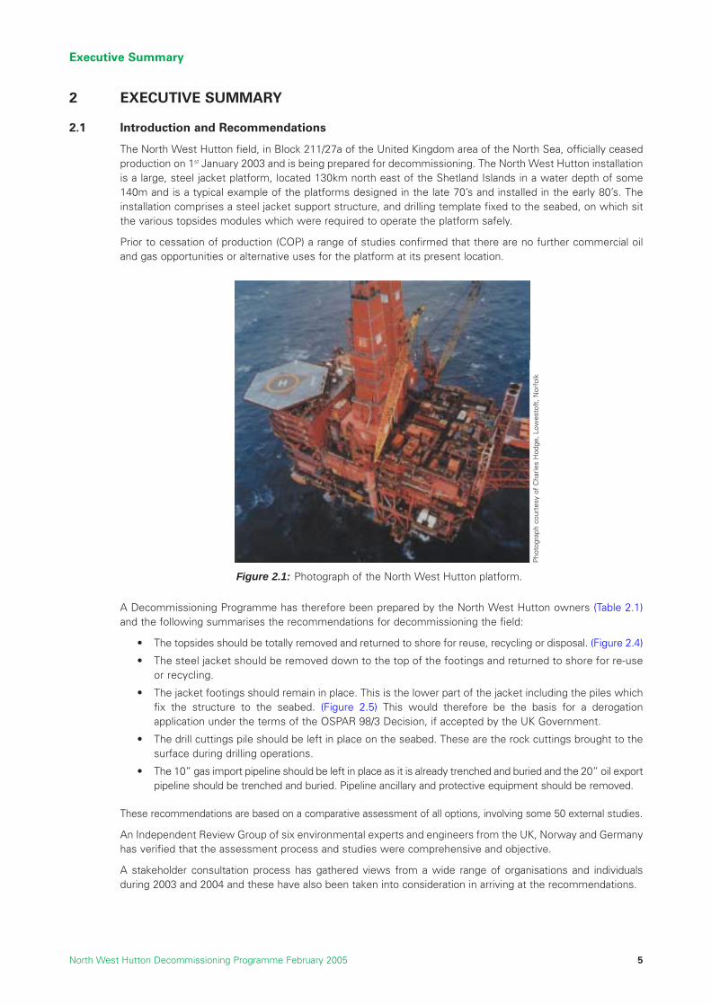
The North West Hutton field, in Block 211/27a of the United Kingdom area of the North Sea, officially ceasedproduction on 1st January 2003 and is being prepared for decommissioning. The North West Hutton installationis a large, steel jacket platform, located 130km north east of the Shetland Islands in a water depth of some140m and is a typical example of the platforms designed in the late 70’s and installed in the early 80’s. Theinstallation comprises a steel jacket support structure, and drilling template fixed to the seabed, on which sitthe various topsides modules which were required to operate the platform safely.
Prior to cessation of production (COP) a range of studies confirmed that there are no further commercial oiland gas opportunities or alternative uses for the platform at its present location.
A Decommissioning Programme has therefore been prepared by the North West Hutton owners (Table 2.1)and the following summarises the recommendations for decommissioning the field:
• The topsides should be totally removed and returned to shore for reuse, recycling or disposal. (Figure 2.4)
• The steel jacket should be removed down to the top of the footings and returned to shore for re-useor recycling.
• The jacket footings should remain in place. This is the lower part of the jacket including the piles whichfix the structure to the seabed. (Figure 2.5) This would therefore be the basis for a derogationapplication under the terms of the OSPAR 98/3 Decision, if accepted by the UK Government.
• The drill cuttings pile should be left in place on the seabed. These are the rock cuttings brought to thesurface during drilling operations.
• The 10” gas import pipeline should be left in place as it is already trenched and buried and the 20” oil exportpipeline should be trenched and buried. Pipeline ancillary and protective equipment should be removed.
These recommendations are based on a comparative assessment of all options, involving some 50 external studies.
An Independent Review Group of six environmental experts and engineers from the UK, Norway and Germanyhas verified that the assessment process and studies were comprehensive and objective.
A stakeholder consultation process has gathered views from a wide range of organisations and individualsduring 2003 and 2004 and these have also been taken into consideration in arriving at the recommendations.
Executive Summary
North West Hutton Decommissioning Programme February 2005 5
Figure 2.1: Photograph of the North West Hutton platform.
Pho
togr
aph
cour
tesy
of
Cha
rles
Hod
ge, L
owes
toft
, Nor
folk

The North West Hutton owners believe that these recommendations provide the most balanced solution forNorth West Hutton, taking account of the safety, environmental, social, technical and economic aspects ofvarious options studied.
During the comparative assessment study and stakeholder consultation processes, certain critical factorsemerged for each of the main elements to be decommissioned which had a major influence on the finalrecommendations:
Topsides – Technical Feasibility and Safety Risk
• Various removal methods are possible but reverse installation is considered to be the preferred optionas offshore deconstruction would involve higher safety risk and single lift technology is not yet available.
• The removal operations will be technically challenging and will require detailed planning and rigorousmanagement to ensure that these activities can be completed safely.
Jacket – Safety Risk, Technical Feasibility and Social Impact
• The three options studied are all technically challenging – full removal, removal to top of footings andpartial removal of footings to the top of the drill cuttings pile.
• A significant differentiator between these options has been the analysis of safety risk. Full or partialremoval of the jacket footings would involve an unacceptable level of safety risk, particularly for thedivers who would be required for key parts of the operation, notably a greatly increased risk of a fatality– a 1 in 7 chance (14%), of someone being killed during full removal operations (13% for partial removalof the footings) compared to a 1 in 20 chance (5%) for removal to the top of the footings. The levels ofrisk for full removal are compared with oil and gas operations and other industries in Figure 2.6.
• Studies undertaken by a Danish engineering consultant have shown that the risk of project failure forpartial and full footings removal was 70% and 45% respectively, due to high levels of technical risk.These are considered to be unacceptably high compared with removal to the top of the footings whichis 23%. (See Figure 2.2)
• Leaving the footings in place and partial removal would present a potential snagging risk for trawlingand would result in the continued exclusion of a small area of the seabed for fishing activities.Measures will be required to minimise this risk.
Drill Cuttings Pile – Environmental and Social Impacts
• The option which provides the least environmental impact is to leave the pile in place to allow theseabed to recover naturally.
• There would be disproportionate resource usage and environmental impact associated with operationsto move or remove the pile.
• Any such operation is likely to result in contamination of areas of the seabed which have alreadyrecovered.
• The seabed in the area is very stable and the pile will remain for a long period but with minimalenvironmental impact.
• Recovery to shore would ultimately involve the use of valuable landfill capacity.
Executive Summary
North West Hutton Decommissioning Programme February 20056
20% 40% 60% 80%
Partial Jacket RemovalAbove Drill Cuttings
Full Jacket & TemplateRemoval
Partial Jacket Removalto Top of Footings
1.2.3.4.5.6.
Structural UncertaintiesCutting ProblemsRigging and LiftingBackloading & SeafasteningTemplate RemovalBottle Legs
1 2 3 4
1 2 3 4 5
1 2 3 4 6
Figure 2.2: Probability of Project Failure. COWI: Removal of the North West Hutton Jacket QuantitativeComparative Assessment 2004.

Pipelines - Technical Feasibility and Social Impact
• Trenching and burying is the best solution as it achieves a similar outcome to total removal but withlower operational safety risk, and energy use and minimises risk to other sea users.
The critical factors identified above for the topsides, jacket, drill cuttings pile and pipelines recommendationsare discussed in more detail later in this Executive Summary and in the full decommissioning programme.
Decommissioning Programmes
The decommissioning programme contains separate programmes for each set of notices served underSection 29 of the Petroleum Act 1998 (Table 1.1, Section 1) for the North West Hutton facilities. TheDecommissioning Programmes are as follows:
Programme 1: Platform and Associated Equipment
• North West Hutton topsides.
• North West Hutton jacket and drilling template.
• Drill cuttings pile present on the seabed at the base of the jacket.
Programme 2: Pipeline PL 147
• 10” gas import pipeline (PL 147) from the Ninian Tee to North West Hutton and associated pipelinesupport equipment on North West Hutton.
Programme 3: Pipeline PL 148
• 20” oil export pipeline (PL 148) from North West Hutton up to the Cormorant ‘A’ tie-in and associatedpipeline support equipment on North West Hutton.
The North West Hutton Decommissioning Programme is set out in accordance with the DTI Guidance Notesfor Industry, ‘Decommissioning of Offshore Installations and Pipelines under the Petroleum Act 1998’ in orderto clearly present the reasoning and activities involved in these programmes. This document incorporates andpresents the three decommissioning programmes as one, which is permitted by the guidelines. Section 29 ofthe Act identifies those parties liable for decommissioning, and the companies liable for the three separateprogrammes are listed in Section 1 of the programme.
The platform is operated by Amoco (UK) Exploration Company, on behalf of Amoco (UK) Petroleum Limited, asubsidiary of BP plc, and here-after will be referred to as BP throughout this Decommissioning Programme.BP operates the field on behalf of the owners with whom the decommissioning responsibility lies. The ownersare shown in Table 2.1.
Executive Summary
North West Hutton Decommissioning Programme February 2005 7
Table 2.1: North West Hutton field owners.
Field Owners Percentage
Amoco (UK) Exploration Company 25.8CIECO Exploration and Production (UK) Limited 25.8Enterprise Oil (UK) Limited 28.4Mobil North Sea Limited 20.0

2.2 Background Information
2.2.1 Environmental Setting
The field is located in the northern North Sea 130km north eastof the Shetland Islands. The water depth is 144m and theweather conditions can be extreme especially in winter.
The marine environment of the North West Hutton field istypical of large areas of the northern North Sea. Marinemammals have been sighted in the area and a variety ofseabirds use the area for feeding and breeding particularly inMay and June. There are no designated conservation areas orvulnerable species in the area. The coral “Lophelia pertusa”grows opportunistically on the subsea jacket structure, which isprotected under the EC Habitat Directive. But the presence ofLophelia does not affect the decommissioning outcome for thejacket because it is opportunistic.
Fishing is the only other significant commercial activity undertaken in the area. The area is classified as of“moderate” economic value for fishing activity, and the level of fishing effort is generally low compared withother areas of the North Sea. Commercial shipping traffic also uses the area although the majority is directlyassociated with oil and gas activity.
2.2.2 Facilities to be Decommissioned
The North West Hutton platform is an integrated oil and gas drilling, production processing and accommodationfacility. It is fairly typical of the larger, steel platforms designed in the late 1970’s and installed in the early 1980’s.
Topsides
The North West Hutton topsides are constructed from individual modules and components, see Figure 2.4.A total of 22 “heavy” lifts were required to install the modules on the support structure and the total weightof the topsides is about 20,000 tonnes. Over 97% of the weight of the topsides comprises carbon steel usedfor the structure and the processing equipment.
Executive Summary
North West Hutton Decommissioning Programme February 20058
NorthSea
ShetlandIslands
Orkney Islands
FaroeIslands
Aberdeen
Bergen
OsloStavanger
North West Hutton
Figure 2.3: Location of North West Hutton.
Production Module
Intake Ducts
Flare Boom
Exhaust Towers forMain Generator Turbines
Utilities Module
Accommodation Block
Pedestal Cranes
Drilling Derricks &Sub-structures
Power GenerationModule
Helideck
Bulk Storage Units
Production Module
Wellheads Module
Exhaust Towers forGas Compressor Turbines
Mud & Drilling Utilities Modules
Figure 2.4: Computer generated diagram of the main components of the topsides on North West Hutton,showing the modular construction.

Jacket
The main support structure, or jacket, is an eight-legged structure weighing about 17,500 tonnes, including theweight of the piles, see Figure 2.5. The jacket was launched from a barge and fixed to the seabed using steelpiles. Before the jacket was positioned in the field, a steel template weighing about 290 tonnes was fixed onthe seabed and this enabled seven wells to be drilled prior to installation of the platform. The template is nowconsidered to be an integral part of the jacket.
The lower part of the jacket - the “footings” - extends to about 40m above the seabed; it comprises very largediameter (5.5m) legs, bracings and piles which together account for about 50% of the total weight of the jacket.
During installation in 1981 some of the members on the lowest level of the jacket were damaged in a storm.Repairs were subsequently made to make the jacket safe for operations, and this resulted in the accumulationof about 100 tonnes of cement grout around the base of the legs.
Executive Summary
North West Hutton Decommissioning Programme February 2005 9
Pile sleeves
Seabed
Piles
Bottle leg
Module SupportFrame
Piles
Corner leg
Pile guides
Footings
Figure 2.5: Computer graphic of the main components of the North West Hutton jacket.

Pipelines
The Decommissioning Programme covers two pipelines, one used for oil export and the other used for gasimport. Both pipelines are constructed of steel and covered with a protective coating of coal tar epoxy. Theouter layer comprises a concrete coating used to protect and also weight the pipeline. Both pipelines areprotected from corrosion by sacrificial anodes. At various locations along each pipeline, concrete mattressesare used to support and protect certain areas such as the crossing of another pipeline.
The 10” gas pipeline (PL 147) is approximately 13km in length and was originally used to export gas to the gastransportation system which lies to the south of North West Hutton. In 1994, it was disconnected andconnected to the Ninian field gas export line, so that North West Hutton could import gas for use as fuel. Thepipeline was trenched to a depth of 0.45m below the seabed at the time of installation. The line is currentlyfully trenched along 100% of its length and buried along approximately 73% of its length.
The 20” oil pipeline (PL 148), jointly owned with the Hutton field, was used to export oil and natural gas liquid(NGL) from the North West Hutton field to Cormorant Alpha which lies approximately 13km to the west. Theoil pipeline has not been trenched and lies on the seabed.
Drill Cuttings Pile
The rock “cuttings” resulting from the drilling operations have accumulated on the seabed around the base ofthe jacket to form a drill cuttings “pile”. During the period of development drilling on North West Huttonbetween 1982 and 1992, the approved and licensed disposal method for these cuttings was to discharge themonto the seabed after cleaning. The pile currently has a maximum depth of 5.5m in the centre and rapidly thinsto approximately 1.5m around the jacket legs. The pile actually extends to between 20m and 70m beyond thejacket legs. The pile has a surface area of approximately 0.02km2 and consists predominantly of rock (48%)and seawater (45%): the remaining material comprises the oil used in the drilling fluid together with smallamounts of other chemicals used in the drilling operations. The total volume of the pile including the seawateris approximately 30,000m3.
2.3 Principles Used to Assess Decommissioning Options
2.3.1 Introduction
The North West Hutton owners used a thorough screening and evaluation process to arrive at therecommended option for decommissioning the North West Hutton facilities. This was designed to assess thetechnical, safety, environmental, financial and societal impacts for all the decommissioning options.
2.3.2 Legal Requirements
The decommissioning of disused offshore installations is governed under UK law by the Petroleum Act 1998.The DTI’s Guidance Notes for Industry on the Decommissioning of Offshore Installations and Pipelines underthe Petroleum Act 1998 also incorporates the UK’s international obligations relating to the disposal of offshoreinstallations which fall under the OSPAR conventions.
OSPAR Decision 98/3 requires that all installations be completely removed to be re-used, recycled or disposed ofon land. A base case of total removal is therefore the starting point of all evaluations and assessments for thedecommissioning of the North West Hutton facilities. However, OSPAR Decision 98/3 allows a potential“derogation”, which is an exemption from the general presumption of total removal for all or part of the “footings”of steel installations weighing more than 10,000 tonnes, and placed in the maritime area before 9th February 1999.
The DTI’s Decommissioning Guidance Notes state that the decommissioning programme should beconsistent with international obligations and take into consideration:
• the precautionary principle
• best available techniques and best environmental practice
• waste hierarchy principles
• other users of the sea
• health and safety law
• proportionality
• cost effectiveness
Executive Summary
North West Hutton Decommissioning Programme February 200510

Executive Summary
North West Hutton Decommissioning Programme February 2005 11
2.3.3 Method and Evaluation Process
Studies Undertaken
The North West Hutton owners commissioned a wide range of detailed studies to fully understand all aspectsof the project. A list of all study references is published in Section 20 of the full Decommissioning Programme.The studies were designed around five key assessment criteria namely:
• Technical feasibility of implementing the operations;
• Safety of all personnel involved in the decommissioning activities both offshore and onshore;
• Environmental impact of all activities at the offshore location and also the onshore dismantling anddisposal site;
• Societal impact on users of the sea, businesses and communities with the potential to be impactedby the decommissioning activity; and
• Financial requirements of the work programme.
Each of the studies was scoped to provide key information related to one or more of the above evaluationcriteria. Complicated modeling and analytical techniques or weightings to combine the five assessment criteriawere not deemed to be applicable.
Each of the studies was implemented by a variety of external contractors, consultants and other specialistsand resulted in the decommissioning recommendations presented for North West Hutton. The range ofstudies completed can be categorised as follows:
• Studies to identify alternatives to decommissioning, or uses for the platform either in the current locationor other locations that align with the intent of the waste hierarchy.
• Removal studies to evaluate the full removal of the North West Hutton platform and all associatedmaterial to achieve a clear seabed.
• Research projects and joint industry projects to better define and understand areas ofdecommissioning generally acknowledged as problematic.
• Comparative assessment studies to describe and compare the alternative options in line with therequirements of the Petroleum Act (1998) and where applicable, OSPAR decision 98/3.
Assurance
To ensure that the study findings are independent and objective, the North West Hutton owners invited aninternational group of engineers and scientists to review all the studies. The Independent Review Group (IRG)has assessed each of the comparative assessment studies for adequacy of scope, clarity, completeness,methodology, relevance and objectivity of conclusions.
The IRG review was completed in April 2004 and a report has been published by the group which is includedin Section 20 and is available on the North West Hutton public website. Amongst other main conclusions, thereport states that:
“The scope of studies undertaken was sufficiently comprehensive, their quality was satisfactory and theyprovide an adequate basis for the comparative assessment process”.
Further details of the IRG terms of reference and conclusions are given in Sections 12 and 20.
Risk Tolerability
The safety risk for decommissioning options was evaluated through the use of quantitative risk assessment(QRA) techniques which provided a numerical evaluation of the risks. The numerical estimates utilise risksexpressed in terms of each worker’s or individual’s risk on an annual basis. An individual’s risk is defined asthe likelihood that a specific individual will be harmed due to exposure to specific hazards. The summation ofeach individual’s risk gives the overall Potential for Loss of Life (PLL) which estimates the collective risk to allworkers involved in removal operations.
For example if a single individual has a risk of 1 x 10⁻³ per year (or 1 in 1000 per year) then out of 1000employees with a similar risk there will be one fatality in any single year. The PLL in this example would be 1 (or 100%) assuming continuous working.

PLL and Individual Risk Per Annum (IRPA) are directly linked in terms of the number of people involved andalso the time spent undertaking the project activities.
The risk is a combination of the likelihood of a hazardous event occurring, the likelihood that someone will bepresent when the event occurs and the likelihood that the specific person will be fatally injured by the effectof the event.
The legislative criteria for acceptability of risk to personnel is that the risk of fatality for an individual shall notbe greater than 1 x 10⁻³ per year (1 in 1000) and shall be as low as is reasonably practicable (ALARP). ALARPis simply a demonstration that all reasonably practicable measures have been taken to reduce risks from eachof the identified hazards and that nothing more can be done to reduce risks further.
The BP criterion for acceptability of risk is that the risk of fatality for an individual shall not be greater than 5 x 10⁻⁴ per year (1 in 2000).
The additional hazards and uncertainties involved in removal of the footings contribute to the high individualrisk values for full jacket removal. A number of these hazards i.e. grout removal and damage to the structureare not prevalent with removal of the upper jacket section and hence individual risks associated with partialremoval are reduced. It is also likely that divers will only be required for footings removal and hence this highrisk is not a factor in partial removal.
Whereas the individual risks are lower for partial removal, certain workers will still carry relatively high levelsof risk as significant hazards remain with the removal of the upper jacket sections. The Deck Crew for examplehas a predicted individual risk of fatality of 1 in 2600 for partial removal against 1 in 2000 for full removal. Itshould be born in mind however that individual risks are presented on an annual basis which partially explainsthe similarity in the figures.
This difference in individual risk between the two options when combined with the differing durations of thetwo options combines to give the overall significant difference in the probability of fatalities between the fulland partial jacket removal options. See Section 2.4.3 for further details.
Evaluation of Impacts
A summary of the criteria and their acceptability levels is shown in Table 2.2; the evaluations are a combinationof qualitative and quantitative impacts. These criteria were used for the evaluation of options for the jacket,drill cuttings and pipelines.
Executive Summary
North West Hutton Decommissioning Programme February 200512
Divers (1 in 600)
Tug Crew (1 in 1400)Estimated disciplinerisks for full jacketremoval
Average Risk for aModern UKCSOperational Platform(1 in 8000)
BroadlyAcceptable
Risk is as Low AsIs Reasonably
PracticableRegion
IncreasingIndividual
Risk
IntolerableRegion
HLV Deck Crew (1 in 2000)
UK Mining & Quarrying(1 in 9000)
1 in 1000/yr
BP Criterion(1 in 2000)
1 in 100,000/yr
UK Driving Risk(1 in 10,000)
Figure 2.6: ALARP Triangle, which compares levels of risk for a sample of individuals involved in the fulljacket removal against other industry and social risks.

Executive Summary
North West Hutton Decommissioning Programme February 2005 13
2.4 Assessment of Decommissioning Options
2.4.1 Alternative Use and Re-use of the Facilities
Studies evaluating the potential re-use of all or part of the North West Hutton facilities in the present locationshow that there are no feasible alternatives to decommissioning. This is primarily due to the remote northernlocation and extreme weather conditions. Possible re-use of the platform at another location is not feasibledue to the age and condition of the equipment and if the equipment was disconnected and moved there isno guarantee it would function satisfactorily. Studies also show that there are no viable commercialopportunities in support of other oil and gas activities in the area. In the absence of such opportunities theonly alternative is to consider decommissioning the facility. Re-use of parts of the facility will be pursued asan alternative to re-cycling.
2.4.2 Topsides Decommissioning
OSPAR Decision 98/3 requires that the topsides of all installations will be returned to shore for re-use orrecycling. The North West Hutton topsides studies therefore examined methods of removal using the fiveevaluation criteria as the means of comparison. The removal methods studied were:
• Offshore deconstruction (piece-small removal).
• Reverse installation.
• Single lift.
The preferred method, based primarily on the safety, and technical criteria, is reverse installation (Section 7.3).
Risk Factors Nature Acceptable Marginal Unacceptable
Safety ofpersonnel
MainlyQuantative
A region of low risk –broadly acceptableregion. Risks in thisarea are generallyregarded asinsignificant andadequately controlled.IRPA is well within therecognised thresholdof 1 in 1000.
A region ofintermediate risk, atolerable region wherepeople are preparedto tolerate the risk tosecure the benefits.IRPA is around therecognised thresholdof 1 in 1000.
A region of high risk- region consideredunacceptablewhatever the levelof benefitassociated with theactivity.IRPA is above therecognisedthreshold of 1 in1000.
Impacts on theenvironment
Quantitative/Qualitative
The proposedoperations mayprovide a benefit, nochange or at worstnegligibleenvironmentalimpacts.
The proposedoperations causesome, possiblysignificant,environmentaldisturbance that islocalised and of shortduration.
The proposedoperations causesignificantenvironmentaldisturbance that iswidespread and/orlong-lasting.
Impacts on society MainlyQualitative
There are tangiblepositive benefits, orpossibly no discerniblenegative impacts.
The proposedoperations may resultin small impacts.
There is potentialfor significantnegative impact.
Technical MainlyQualitative
Equipment andtechniques are knownand have a trackrecord of success.
Equipment andtechniques have alimited track record orrequire development.
Equipment andtechniques have notrack record.
Economic Quantitative Cost is important but is not used as a prime differentiator. It isincluded for completeness and as a measure of proportionality whenconsidering the other four criteria.
Table 2.2: Summary of criteria and acceptability levels for options fordecommissioning the jacket.

The studies indicate that removal of the topsides by reverse installation is feasible. All components of thetopsides will be returned to shore for re-use, recycling or disposal. This will involve 22 lifts up to a maximumlift of 2,800 tonnes. The studies indicate that the operation will be technically challenging but achievable, andthe environmental assessment does not identify any major risks. The safety assessment indicates that thisaspect of the project carries significant risks to personnel both offshore and at the onshore decommissioningsite.
A number of hazards are predicted which may expose key disciplines to potentially high levels of individualrisk. However, unlike jacket removal which involves a high degree of uncertainty and technical challenge, theability to thoroughly assess the topsides modules prior to lifting may provide opportunities to eliminate orreduce the impact of these hazards further, thereby reducing overall risk.
The analysis undertaken includes an estimated 6 months preparatory work phase involving high manninglevels to prepare for module removal. This preparatory phase, though not high risk, significantly contributes tothe overall risk through exposure to normal offshore risks e.g. helicopter travel.
The significant number of personnel involved combined with an extended timescale for removal results in arelatively high level of risk for topsides removal. Opportunities to reduce the overall exposure time toindividuals will also reduce the removal risk.
The overall risk of a fatality occurring during operations to remove and re-use or recycle the topsides isestimated to be around 9.6% or a 1 in 10 chance of a fatality during the project.
This assessment of safety risk indicates that whilst feasible, all activities associated with topsides removal willrequire rigorous design, assessment and management to ensure that risk to personnel is minimised.
Recommendation: The North West Hutton topsides should be totally removed andreturned to shore for re-use, recycling or disposal.
2.4.3 Jacket Decommissioning
The drill cuttings and jacket have been evaluated separately in the comparative assessments to ensure eachwas considered on its own merits. This is a major factor in the jacket study work, because most of the drillcuttings would have to be removed to gain access to the base of the footings, seabed brace members andthe template for complete jacket removal.
The North West Hutton jacket is the largest fixed steel, offshore oil and gas structure that has been consideredfor decommissioning anywhere in the world to date. A wide range of study work was implemented and theoverall purpose was to:
• identify all of the currently available techniques, and the potential new techniques, for jacket removal;and
• assess the technical, safety, environmental, societal and cost implications of removing the North WestHutton jacket with the preferred technique.
Executive Summary
North West Hutton Decommissioning Programme February 200514
Figure 2.7: Photographs of the North West Hutton Jacket.
Pho
togr
aphs
cou
rtes
y of
Cha
rles
Hod
ge, L
owes
toft
, Nor
folk

Executive Summary
North West Hutton Decommissioning Programme February 2005 15
Techniques for Removal of the Jacket
Three main techniques for removal of the jacket were identified and evaluated, as follows:
Reverse Installation and Single LiftThese two methods would involve removal of the entire jacket by buoyancy methods or a purpose-built vessel.No equipment to implement such operations currently exists. Studies have shown that the damage sustainedduring the installation of the platform has left the jacket unable to withstand the forces that would be imparted bysuch a removal technique. The size of the jacket, the presence of the excess grout from the installation difficultiesand the severe and unpredictable weather of the remote location of North West Hutton are also problematic andare not best suited to the first use of a major new technique.
Offshore DeconstructionThis method would involve the major use of underwater cutting techniques and large offshore cranes, similarto those used for the topsides removal, to remove the jacket in sections. Offshore deconstruction has beenused before but proved highly complex. It is not directly comparable with the technique of reverse installationto be used for the topsides, and is a considerable extrapolation from any work previously undertaken.
Overall, the studies indicate that offshore deconstruction is the most feasible and viable method forjacket removal. This method therefore formed the basis for comparison of the jacket removal options.This does not preclude other methods coming forward in the future.
Jacket Removal Operations
The study work evaluated in detail all aspects of the offshore deconstruction operations required for fullremoval of the jacket. The operations are theoretically achievable and utilise existing technologies, but noequipment to handle, cut and lift the components the size of the North West Hutton jacket is currentlyavailable. The deconstruction activity would involve the progressive cutting and removal of the jacket, startingat the surface and gradually working downwards. At least 20 lifts weighing up to 3,000 tonnes would berequired. The largest jacket removal to date, involved three major lifts.
The base of the jacket was severely damaged by a storm during its installation and as a result of this damagethere is also a large quantity of excess grout around the base of the four legs, and in particular Leg B1.
These technical considerations and the fact that the North West Hutton jacket may be a candidate forderogation, led to the comparative assessment of three options for the decommissioning of the North WestHutton jacket. These options were developed during the course of the work and were suggested by theIndependent Review Group (IRG) and supported by the DTI. The presumption remains that of clear seabed,but the three options selected were:
• Total jacket and template removal to provide a clear seabed.
• Removal of all jacket components down to the top of the drill cuttings pile.
• Removal of all jacket components down to the top of the footings.
Comparative Assessment
The study focus was on the full removal of the jacket. A significant number of potential major hazards wereidentified by the studies and the main areas of concern were:
• Reliability of subsea cutting and rigging technology particularly for critical cuts immediately prior to thelift and the large leg cuts.
• Dropped loads.
• Falling objects during all aspects of operations.
• Transfer of the irregular loads to moving barges offshore, and securing activities of this scale.
• The likely requirement for the use of divers in major deconstruction activities.
• Onshore demolition and dismantling.
These activities are similar for the full and partial removal options although there are major variations, such ascutting through the large diameter legs (“bottle legs”), and these were included in the studies. Each bottle leg

is approximately 5.5m in diameter and has five piles, each with a diameter of 1.5m This allowed the threeoptions to be compared in detail to fully understand the implications of each. The results of the studies arepresented in the Table 2.3 using the safety, environmental, societal, technical and economic evaluation criteriaas the basis for the comparison.
Option - Jacket and Footings Partial Removal down to top of Drill Cuttings
This option is similar in safety and environmental exposure to that of the full removal option; see the similarityof data for these criteria in table 2.3. However the partial removal option does not leave a clear seabed and thesite would remain an obstruction for fishing, which is the main societal impact. Parts of the structure that remainwould still protrude out of the drill cuttings up to a height of 10 metres above the seabed, as this is the lowestlevel at which it is feasible to cut the large bottle legs, due to the stiffening and braces at the lower levels. Thetechnical challenge is significant for this option, and as can be seen from the table the risk of project failure ispredicted by an independent report as 70%. This is higher than the complete removal option at 45%. This isalso reflected in the costs which are higher for partial removal than the complete removal option.
Comparing this partial removal option with that of the removal of the jacket down to the top of the footingsshows that for removal to the top of the footings there is less safety and environmental risk. The fishingobstruction remains, but that is the same for both the options. Technically and financially removal to the topof the footings is better, as it has a much lower risk of project failure at 23%.
To summarise, the partial removal option is less favourable than the complete removal option as there is ahigher technical risk and it does not remove the obstruction to fishing. It is less favourable than removal to thetop of the footings option because there is a much higher safety and technical risk, and the two options aresimilar with regard to fishing.
This option is therefore eliminated from further consideration. The two options of full jacket and footingsremoval and removal of the jacket to the top of the footings, i.e. derogation, are now considered further.
Comparison of Total Jacket Removal and Removal to the top of the Footings
The risk of project failure was determined by an independent consultant from Denmark. The conclusion wasthat there was a much greater risk of project failure that is, severe difficulties in completing the work, cost andschedule over-runs, for the complete removal (45%) than the removal to the top of the footings (23%). Thefigure used in BP to define a serious over-run, or ‘project failure’ is 15%. These figures clearly show that allactivity associated with the removal of the jacket entails high levels of technical risk, but that work on thefootings is significantly more difficult.
Such risks are considered unacceptable in terms of industry and BP standards. Even allowing for reasonableimprovements from mitigation measures, the risks remain high. A significant proportion of the risk isattributable to removal of the lower-most components due to existing damage and the large accumulations ofgrout around the legs. This combination of damage and excess grout around the legs is not normal and is asignificant factor in the removal operation.
Executive Summary
North West Hutton Decommissioning Programme February 200516
Summary of Jacket and Footings OptionsJacket and
Footings Removal
Jacket and Footings Partial
RemovalJacket Removal to -
100m
Safety Probability of Loss of Life 14% 13% 5%Number of Lost Time Injuries (LTI) 16 15 6
Environment GHG CO2E Tonnes 42,000 44,000 38,000Total Energy requirement GJ 520,000 568,000 559,000Footprint km2 None <0.01 <0.01Persistence years None >500 years >500 years
Societal Impact on Fisheries None No go fishing area No go fishing areaUK Employment Impact Man/years 196 not studied 66
Technical Technical risk of failure 45% 70% 23%Damage to
footings
Cutting/rigging difficulty and complexity
Economics Cost See Section 13 for Cost Information
Cutting bottles is high technical risk
Cutting/rigging difficulty and complexity
Table 2.3: Summary of jacket and footings decommissioning options.

Executive Summary
North West Hutton Decommissioning Programme February 2005 17
It is also likely that divers would be needed to assess the damage for feasibility of lifting somecomponents and to remove some grout for safety reasons, i.e. the grout is liable to fall during lifting withthe risk of injury to personnel.
The other technical risks that have been discussed qualitatively above, are quantified in the 45% and 23%figures. These are the increased difficulty of cutting and rigging at the greater depths of the footings andtransferring these loads to the transportation barges. All the above technical difficulties are reflected in thecosts, where full removal is about twice the cost of removal to the top of the footings.
More importantly these technical risks are reflected in the safety exposure for the two options. The calculatedPotential Loss of Life (PLL) is estimated as 14% (1 in 7 chance of a fatality during a project) and 5% (1 in 20chance), for total removal and removal to the top of the footings respectively. The number of accidents, referredto as a Lost Time Incident (LTI), for the two options is calculated as 16 and 6 respectively. This is the numberof potential serious accidents that would mean personnel were not able to return to work for at least three days.This is almost a three-fold increase in the safety risk associated with footings removal, which is a very significantincrease in the risk of someone being killed. See Figure 2.6 for further risk of fatality analysis for this option.
On a like for like basis, North West Hutton as an operational production platform with major hydrocarbonhazards, operated with approximately one quarter of the fatality risk associated with jacket removal.
It should be noted that the use of analytical methods in determining the risk of fatalities tends tounderestimate, rather than overestimate, the risk to personnel. This is evident in the fact that fatalities haveoccurred in several decommissioning projects to date.
The studies do not identify any significant environmental hazards and the CO2 emissions and energy usebalance are broadly similar for the two options. This is because the extra energy used for removing andrecycling a greater proportion of the steel (i.e. jacket and footings removal) is offset by the indirect energy costof leaving steel on the seabed (jacket removal to -100m), and the theoretical need therefore to manufacturenew steel to replace recyclable steel left on the seabed.
Neither option would hinder free passage of ships so all collision risk is eliminated. Leaving the footings on theseabed would present an obstruction to commercial fishing operations in the area, but would not affect the overallavailable catch. The possibility of fishing equipment becoming snagged on the structure which remains on theseabed is recognised, but the probability that such an event would occur, given the mitigation measures that wouldbe in place, is considered to be low. These mitigation measures will be the subject of consultation with relevantfishing organisations and are expected to include the use of guard vessels during decommissioning operations andthe updating of Kingfisher Information Service bulletins and the FishSafe database to ensure that a change ofdesignation from ‘installation’ to ‘obstruction’ is effectively communicated.
On the basis of the above factors, the assessment indicates that the level of risk associated with the removalof the footings is not proportional to the benefits. An almost three-fold increase in the risk of a fatality duringthe operations to remove and dispose of the footings is deemed unacceptable. The complexity and risk ofremoving the footings of a large structure is acknowledged by OSPAR Decision 98/3 for jackets weighing over10,000 tonnes. The recommendation is therefore to leave the footings of the North West Hutton jacket in place.
Recommendation: The North West Hutton jacket should be removed down to the top ofthe footings (Figure 2.8) and returned to shore for reuse or recycling. The footingsstructure should remain in-situ.
Figure 2.8: Computer graphic of the North West Huttonsupport structure after removal to the top of the footings.
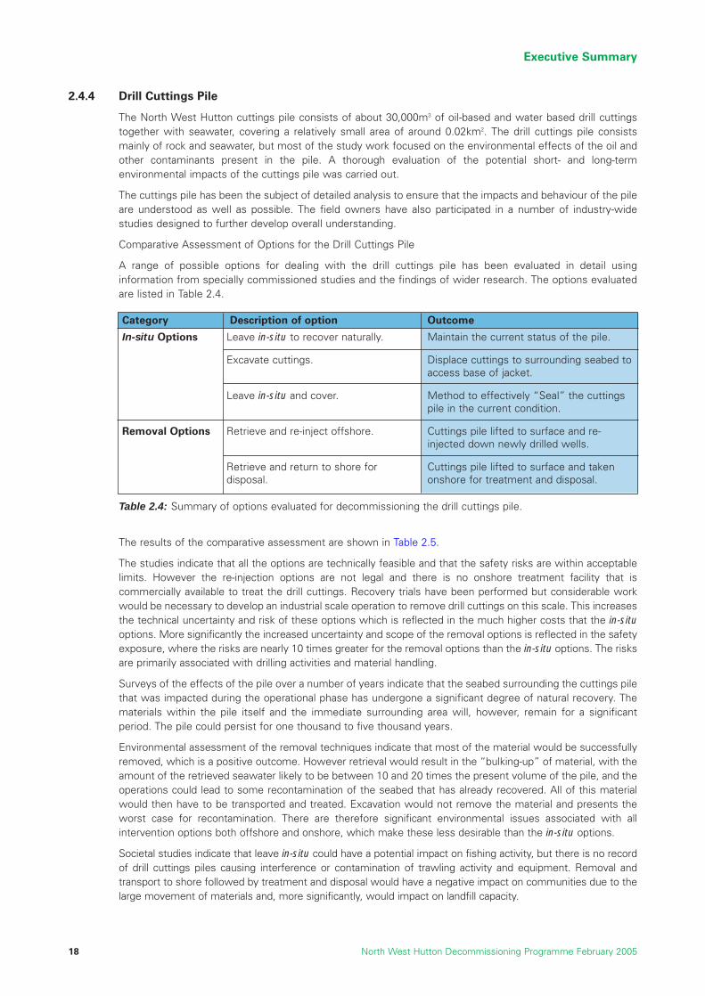
2.4.4 Drill Cuttings Pile
The North West Hutton cuttings pile consists of about 30,000m3 of oil-based and water based drill cuttingstogether with seawater, covering a relatively small area of around 0.02km2. The drill cuttings pile consistsmainly of rock and seawater, but most of the study work focused on the environmental effects of the oil andother contaminants present in the pile. A thorough evaluation of the potential short- and long-termenvironmental impacts of the cuttings pile was carried out.
The cuttings pile has been the subject of detailed analysis to ensure that the impacts and behaviour of the pileare understood as well as possible. The field owners have also participated in a number of industry-widestudies designed to further develop overall understanding.
Comparative Assessment of Options for the Drill Cuttings Pile
A range of possible options for dealing with the drill cuttings pile has been evaluated in detail usinginformation from specially commissioned studies and the findings of wider research. The options evaluatedare listed in Table 2.4.
The results of the comparative assessment are shown in Table 2.5.
The studies indicate that all the options are technically feasible and that the safety risks are within acceptablelimits. However the re-injection options are not legal and there is no onshore treatment facility that iscommercially available to treat the drill cuttings. Recovery trials have been performed but considerable workwould be necessary to develop an industrial scale operation to remove drill cuttings on this scale. This increasesthe technical uncertainty and risk of these options which is reflected in the much higher costs that the in-situoptions. More significantly the increased uncertainty and scope of the removal options is reflected in the safetyexposure, where the risks are nearly 10 times greater for the removal options than the in-situ options. The risksare primarily associated with drilling activities and material handling.
Surveys of the effects of the pile over a number of years indicate that the seabed surrounding the cuttings pilethat was impacted during the operational phase has undergone a significant degree of natural recovery. Thematerials within the pile itself and the immediate surrounding area will, however, remain for a significantperiod. The pile could persist for one thousand to five thousand years.
Environmental assessment of the removal techniques indicate that most of the material would be successfullyremoved, which is a positive outcome. However retrieval would result in the “bulking-up” of material, with theamount of the retrieved seawater likely to be between 10 and 20 times the present volume of the pile, and theoperations could lead to some recontamination of the seabed that has already recovered. All of this materialwould then have to be transported and treated. Excavation would not remove the material and presents theworst case for recontamination. There are therefore significant environmental issues associated with allintervention options both offshore and onshore, which make these less desirable than the in-situ options.
Societal studies indicate that leave in-situ could have a potential impact on fishing activity, but there is no recordof drill cuttings piles causing interference or contamination of trawling activity and equipment. Removal andtransport to shore followed by treatment and disposal would have a negative impact on communities due to thelarge movement of materials and, more significantly, would impact on landfill capacity.
Executive Summary
North West Hutton Decommissioning Programme February 200518
Category Description of option Outcome
In-situ Options
Removal Options
Leave in-situ to recover naturally.
Excavate cuttings.
Leave in-situ and cover.
Retrieve and re-inject offshore.
Retrieve and return to shore fordisposal.
Maintain the current status of the pile.
Displace cuttings to surrounding seabed toaccess base of jacket.
Method to effectively “Seal” the cuttingspile in the current condition.
Cuttings pile lifted to surface and re-injected down newly drilled wells.
Cuttings pile lifted to surface and takenonshore for treatment and disposal.
Table 2.4: Summary of options evaluated for decommissioning the drill cuttings pile.

Executive Summary
North West Hutton Decommissioning Programme February 2005 19
The environmental assessment showed that in spite of the predicted longevity of the pile if left in-situ and evenallowing for occasional minor disturbance, the impact of the pile would be minimal, and recovery of the seabedwould proceed albeit very slowly. There would be disproportionate risk, resource usage and environmental impactsassociated with operations to move or remove the pile. The recommended option is therefore to leave the pile in-situ to recover naturally, and this is also the best environmental option. This course of action does not change thecurrent status of the pile. The pile would be monitored and subject to on going surveys to check that the seabedrecovery process is as expected. We will also continue to monitor future discussions and decisions under theOSPAR framework for their relevance to the North West Hutton pile.
Recommendation: The North West Hutton drill cuttings pile should be left in-situ torecover naturally.
2.4.5 Pipeline Decommissioning – PL 147 and PL 148
As with the other components of the North West Hutton infrastructure, the history, current status and optionsfor the pipelines were studied in detail. The gas pipeline PL 147 is currently trenched to 0.45m below theseabed and rock-dumped and self-buried. The oil pipeline PL 148 lies on the seabed. Throughout their lives thepipelines have been surveyed and maintained, and the survey record shows that the seabed is stable and thatno major spans have developed.
The options studied for the pipelines were as follows:
• Leave in-situ on the seabed
• Trench and bury to below the seabed
• Recover the pipelines.
The results of the comparative assessment of these three options are shown in Table 2.6
Leave in situ & Monitor Cover Excavate
Re-inject on site
Re-inject offsite Onshore treatment
Safety Probability of Loss of Life 0.20% 0.6% 0.50% 6.4% 6.4% 2.2%Number of Lost Time Injuries (LTI) <1 <1 <1 7 7 3
Environment Total Energy requirement (GJ)
6,500 73,000 33,000 275,000 298,000 419,000
GHG CO2 E (tonnes) 500 6000 3000 20,000 22,000 186,000Footprint (km2) 0.02 0.02 >0.02 Negligible Negligible Negligible
Persistence (years) 1000-5000 Irreversible <1000-5000 Negligible Negligible Negligible
Recovery in surr seabed
Resources needed 90,000
tonnes/rock
Landfill capacity >300,000 m3
Societal Potential fisheries
interactionUK Employment Impact (Man yrs) 1.6 not studied not studied 301 not studied 242Tax Impact to Society (£mm) 0.2 3.0 4.0 17-44 17-44 18-46
Technical Yes Feasible Feasible
Tech feasible but
not legal
Tech feasible but
not legal
Onshore treatment not commercially
available
Economics Cost (£mm) 0.5 8 9 43-110 43-110 46-114
Recovery needs development from trial to industrial scale
Summary of Drill Cuttings Options
Table 2.5: Summary of the decommissioning options for the drill cuttings pile.
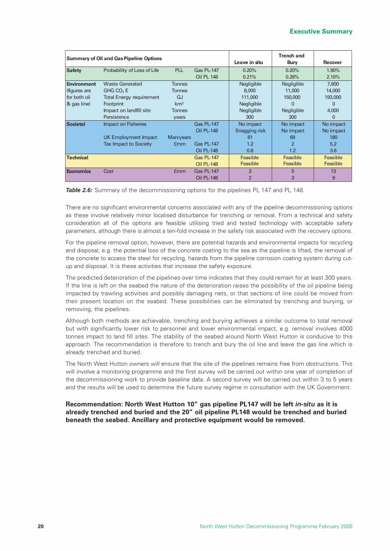
There are no significant environmental concerns associated with any of the pipeline decommissioning optionsas these involve relatively minor localised disturbance for trenching or removal. From a technical and safetyconsideration all of the options are feasible utilising tried and tested technology with acceptable safetyparameters, although there is almost a ten-fold increase in the safety risk associated with the recovery options.
For the pipeline removal option, however, there are potential hazards and environmental impacts for recyclingand disposal; e.g. the potential loss of the concrete coating to the sea as the pipeline is lifted, the removal ofthe concrete to access the steel for recycling, hazards from the pipeline corrosion coating system during cut-up and disposal. It is these activities that increase the safety exposure.
The predicted deterioration of the pipelines over time indicates that they could remain for at least 300 years.If the line is left on the seabed the nature of the deterioration raises the possibility of the oil pipeline beingimpacted by trawling activities and possibly damaging nets, or that sections of line could be moved fromtheir present location on the seabed. These possibilities can be eliminated by trenching and burying, orremoving, the pipelines.
Although both methods are achievable, trenching and burying achieves a similar outcome to total removalbut with significantly lower risk to personnel and lower environmental impact, e.g. removal involves 4000tonnes impact to land fill sites. The stability of the seabed around North West Hutton is conducive to thisapproach. The recommendation is therefore to trench and bury the oil line and leave the gas line which isalready trenched and buried.
The North West Hutton owners will ensure that the site of the pipelines remains free from obstructions. Thiswill involve a monitoring programme and the first survey will be carried out within one year of completion ofthe decommissioning work to provide baseline data. A second survey will be carried out within 3 to 5 yearsand the results will be used to determine the future survey regime in consultation with the UK Government.
Recommendation: North West Hutton 10” gas pipeline PL147 will be left in-situ as it isalready trenched and buried and the 20” oil pipeline PL148 would be trenched and buriedbeneath the seabed. Ancillary and protective equipment would be removed.
Executive Summary
North West Hutton Decommissioning Programme February 200520
Leave in situTrench and
Bury Recover
Safety Probability of Loss of Life PLL Gas PL-147 0.20% 0.20% 1.90%Oil PL 148 0.21% 0.28% 2.10%
Environment Waste Generated Tonnes Negligible Negligible 7,600(figures are GHG CO2 E Tonnes 8,000 11,000 14,000for both oil Total Energy requirement GJ 111,000 150,000 193,000& gas line) Footprint km2 Negligible 0 0
Impact on landfill site Tonnes Negligible Negligible 4,000Persistence years 300 300 0
Societal Impact on Fisheries Gas PL-147 No impact No impact No impactOil PL-148 Snagging risk No impact No impact
UK Employment Impact Man/years 61 69 180Tax Impact to Society £mm Gas PL-147 1.2 2 5.2
Oil PL-148 0.8 1.2 3.6Technical Gas PL-147 Feasible
FeasibleFeasibleFeasible
FeasibleFeasibleOil PL-148
Economics Cost £mm Gas PL-147 3 5 13Oil PL-148 2 3 9
Summary of Oil and Gas Pipeline Options
Table 2.6: Summary of the decommissioning options for the pipelines PL 147 and PL 148.
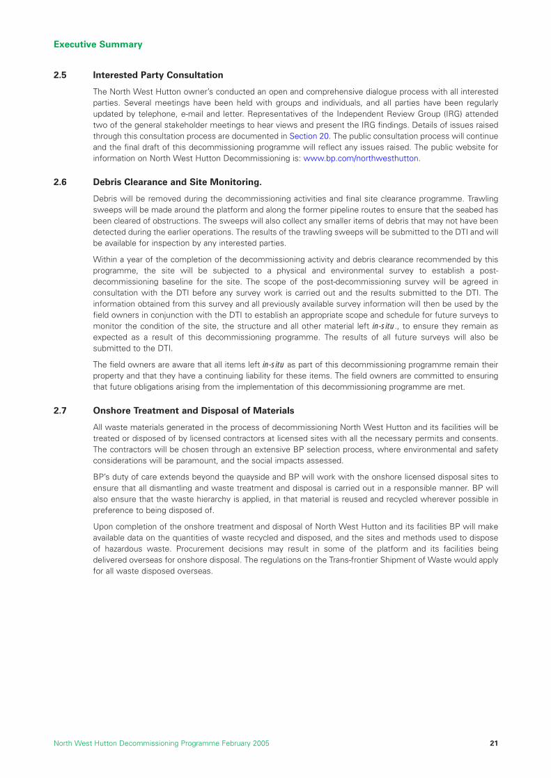
Executive Summary
North West Hutton Decommissioning Programme February 2005 21
2.5 Interested Party Consultation
The North West Hutton owner’s conducted an open and comprehensive dialogue process with all interestedparties. Several meetings have been held with groups and individuals, and all parties have been regularlyupdated by telephone, e-mail and letter. Representatives of the Independent Review Group (IRG) attendedtwo of the general stakeholder meetings to hear views and present the IRG findings. Details of issues raisedthrough this consultation process are documented in Section 20. The public consultation process will continueand the final draft of this decommissioning programme will reflect any issues raised. The public website forinformation on North West Hutton Decommissioning is: www.bp.com/northwesthutton.
2.6 Debris Clearance and Site Monitoring.
Debris will be removed during the decommissioning activities and final site clearance programme. Trawlingsweeps will be made around the platform and along the former pipeline routes to ensure that the seabed hasbeen cleared of obstructions. The sweeps will also collect any smaller items of debris that may not have beendetected during the earlier operations. The results of the trawling sweeps will be submitted to the DTI and willbe available for inspection by any interested parties.
Within a year of the completion of the decommissioning activity and debris clearance recommended by thisprogramme, the site will be subjected to a physical and environmental survey to establish a post-decommissioning baseline for the site. The scope of the post-decommissioning survey will be agreed inconsultation with the DTI before any survey work is carried out and the results submitted to the DTI. Theinformation obtained from this survey and all previously available survey information will then be used by thefield owners in conjunction with the DTI to establish an appropriate scope and schedule for future surveys tomonitor the condition of the site, the structure and all other material left in-situ., to ensure they remain asexpected as a result of this decommissioning programme. The results of all future surveys will also besubmitted to the DTI.
The field owners are aware that all items left in-situ as part of this decommissioning programme remain theirproperty and that they have a continuing liability for these items. The field owners are committed to ensuringthat future obligations arising from the implementation of this decommissioning programme are met.
2.7 Onshore Treatment and Disposal of Materials
All waste materials generated in the process of decommissioning North West Hutton and its facilities will betreated or disposed of by licensed contractors at licensed sites with all the necessary permits and consents.The contractors will be chosen through an extensive BP selection process, where environmental and safetyconsiderations will be paramount, and the social impacts assessed.
BP’s duty of care extends beyond the quayside and BP will work with the onshore licensed disposal sites toensure that all dismantling and waste treatment and disposal is carried out in a responsible manner. BP willalso ensure that the waste hierarchy is applied, in that material is reused and recycled wherever possible inpreference to being disposed of.
Upon completion of the onshore treatment and disposal of North West Hutton and its facilities BP will makeavailable data on the quantities of waste recycled and disposed, and the sites and methods used to disposeof hazardous waste. Procurement decisions may result in some of the platform and its facilities beingdelivered overseas for onshore disposal. The regulations on the Trans-frontier Shipment of Waste would applyfor all waste disposed overseas.
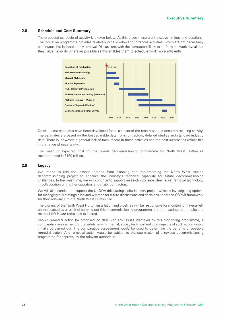
2.8 Schedule and Cost Summary
The proposed schedule of activity is shown below. At this stage these are indicative timings and durations.The indicative programme provides relatively wide windows for offshore activities, which are not necessarilycontinuous, but indicate timely removal. Discussions with the contractors likely to perform the work reveal thatthey value flexibility wherever possible as this enables them to schedule work more efficiently.
Detailed cost estimates have been developed for all aspects of the recommended decommissioning activity.The estimates are based on the best available data from contractors, detailed studies and standard industrydata. There is, however, a general lack of track record in these activities and the cost summaries reflect thisin the range of uncertainty.
The mean or expected cost for the overall decommissioning programme for North West Hutton asrecommended is £160 million.
2.9 Legacy
We intend to use the lessons learned from planning and implementing the North West Huttondecommissioning project to enhance the industry’s technical capability for future decommissioningchallenges. In the meantime, we will continue to support research into large steel jacket removal technologyin collaboration with other operators and major contractors.
We will also continue to support the UKOOA drill cuttings joint industry project which is investigating optionsfor managing drill cuttings piles and will monitor future discussions and decisions under the OSPAR frameworkfor their relevance to the North West Hutton pile.
The owners of the North West Hutton installation and pipelines will be responsible for monitoring material lefton the seabed as a result of carrying out this decommissioning programme and for ensuring that the site andmaterial left in-situ remain as expected.
Should remedial action be proposed, to deal with any issues identified by this monitoring programme, acomparative assessment of the safety, environmental, social, technical and cost impacts of such action wouldinitially be carried out. The comparative assessment would be used to determine the benefits of possibleremedial action. Any remedial action would be subject to the submission of a revised decommissioningprogramme for approval by the relevant authorities.
Executive Summary
North West Hutton Decommissioning Programme February 200522
Cessation of Production
Well Decommissioning
Clean & Make-safe
Module Separation
NUI / Removal Preparation
Pipeline Decommissioning (Window)
Platform Removal (Window)
Onshore Disposal (Window)
Debris Clearance & Final Survey
01/01/03
2003 2004 2005 2006 2007 2008 2009 2010
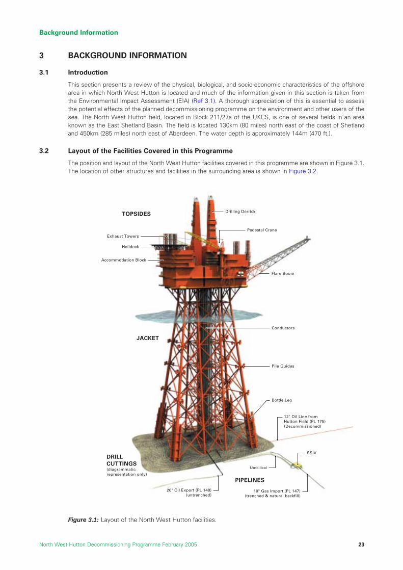
3 BACKGROUND INFORMATION
3.1 Introduction
This section presents a review of the physical, biological, and socio-economic characteristics of the offshorearea in which North West Hutton is located and much of the information given in this section is taken fromthe Environmental Impact Assessment (EIA) (Ref 3.1). A thorough appreciation of this is essential to assessthe potential effects of the planned decommissioning programme on the environment and other users of thesea. The North West Hutton field, located in Block 211/27a of the UKCS, is one of several fields in an areaknown as the East Shetland Basin. The field is located 130km (80 miles) north east of the coast of Shetlandand 450km (285 miles) north east of Aberdeen. The water depth is approximately 144m (470 ft.).
3.2 Layout of the Facilities Covered in this Programme
The position and layout of the North West Hutton facilities covered in this programme are shown in Figure 3.1.The location of other structures and facilities in the surrounding area is shown in Figure 3.2.
Background Information
North West Hutton Decommissioning Programme February 2005 23
(diagrammaticrepresentation only)
10" Gas Import (PL 147)(trenched & natural backfill)
20" Oil Export (PL 148)(untrenched)
12" Oil Line from Hutton Field (PL 175) (Decommissioned)
TOPSIDES
JACKET
DRILLCUTTINGS
PIPELINES
SSIV
Conductors
Bottle Leg
Drilling Derrick
Flare Boom
Pedestal Crane
Accommodation Block
Helideck
Exhaust Towers
Pile Guides
Umbilical
Figure 3.1: Layout of the North West Hutton facilities.

3.3 Adjacent Facilities
The North West Hutton platform has three pipeline connections which were used to import and export oil andgas. The pipelines are shown in Figure 3.2.
Oil production from the North West Hutton Field was exported via the 20” oil pipeline PL 148 to the Cormorant‘A’ platform, located approximately 13km to the west. Oil from the North West Hutton pipeline was thenpumped from Cormorant ‘A’ to the Sullom Voe oil terminal via the “Brent System” pipeline together with oilfrom a number of other fields. In the years leading up to cessation of production, the volume of oil exporteddecreased and in its last year of production North West Hutton accounted for only 0.1% of the throughput atSullom Voe. The economic impact of the cessation of production at North West Hutton on Cormorant ‘A’, theBrent Pipeline System and the Sullom Voe terminal is therefore insignificant.
In the early years of production, excess gas (referred to as “associated gas”) produced together with the oilat North West Hutton was exported to St Fergus in North Eastern Scotland for use as fuel onshore. The NorthWest Hutton 10” gas pipeline PL 147 was installed to export this gas from North West Hutton to a subseaconnection in the “FLAGS - Far North Liquids and Associated Gas System” system located approximately13km south of North West Hutton. In 1989, as oil production from North West Hutton declined, the volumeof gas also declined to a point where there was insufficient to supply the fuel requirements for the platform.As a result, PL 147 was disconnected from the FLAGS system and a new subsea connection was made tothe nearby gas export pipeline from the Ninian field. PL 147 was then used to import gas to supplement thefuel gas supply for North West Hutton. This gas import ceased in late 2003 as North West Hutton wasprepared for decommissioning. There will be no material impact on the Ninian field and surrounding fields asthe relatively small volumes of gas previously purchased by North West Hutton will be either exported for saleor used as fuel for the Ninian field.
A third pipeline PL 175 was connected to North West Hutton to enable oil from the Hutton field in Block211/28 (operated by Kerr McGee) to be transported onwards to Sullom Voe via the North West Hutton oilexport pipeline, PL1 48 and the Brent system. The Hutton field Tension Leg Platform was locatedapproximately 8km east of North West Hutton. Pipeline PL 175 has been disconnected from North WestHutton and was decommissioned in 2001 by the Hutton owners as part of the separate Hutton fielddecommissioning programme (Ref. 3.3).
All operational activities associated with the three pipelines have now ceased, and the decision todecommission North West Hutton will have no material economic or other impact on adjacent fields orfacilities.
Background Information
North West Hutton Decommissioning Programme February 200524
Figure 3.2: North West Hutton and adjacent facilities.

3.4 Physical, Meteorological and Oceanographic Conditions
Table 3.1 summarises information about the physical, meteorological and oceanographic conditions at NorthWest Hutton and the area immediately around the platform. More detailed information, which may have beenused in some of the technical and environmental impact assessments which were conducted to support thisdecommissioning programme, may be found in the Appendices or the reports listed in the references.
Over the past 20 years many aspects of the offshore environment of the East Shetland basin have beenstudied in detail, during field-specific surveys and monitoring programmes, and as part of wider-areasurveys. BP has carried out numerous surveys around and centred on the North West Hutton location, andthese are listed below in Table 3.2. These surveys, in conjunction with the United Kingdom OffshoreOperators Association (UKOOA) Drill Cuttings JIP study (Ref: 3.16) make the North West Hutton pile andsurrounding seabed one of the most comprehensively investigated in the UKCS.
Background Information
North West Hutton Decommissioning Programme February 2005 25
YearTransectDirection
No.Stations
Hydrocarbons Metals Biology
1985 NE/SE 9 Yes No No1989 NE/SE 12 Yes No No
1992 N12
Yes Yes Yes
1997 N 11Yes
No Yes
1999 N 26 Yes No Yes
2002 N & ESE 17 Yes Yes Yes
2003N/A
(Survey ofcuttings pilebelow jacket)
11 Yes NE/SE Yes
Notes
3-D mapping of pile; vibro-coring, grain sizeand radioisotope study.
Sampling along the 1992 transect from 50m-400m and 7,500m
Survey from 1992 transect 100m-10,000mSurvey of combined 1992 and 1985 stations.Measured granulometry and a subset ofsamples for PAH, LSA, PCB, TBT and APEcompounds.Samples at depth during conductor removaloperations, plus surface of cuttings pilebelow jacket. Samples of cuttings pile alsoanalysed for PAH, PCB.
Table 3.2: Summary of sampling from North West Hutton seabed and cuttings pile. (Ref. 3.6)
Aspect Information
Platform locationSeabed surface soil typeWater depthMaximum tidal rangeNearest landNearest platformDistance to median line
61 06’23.950”N, 01 18’32.974”E Sand, silt, and very stiff to very hard clay144.3m LAT2.3mThe Shetland Islands, 130km (80 miles) south-southwestCormorant ‘A’, 13km westMedian line with Norway is 25 km east
Waves 1 year 50 years
Significant wave heightMaximum wave height
11.6m21.6m
16.1m29.9m
Currents 1 year 50 years
Maximum surface speedMaximum seabed speed
0.73m/sec0.47m/sec
0.82m/sec0.53m/sec
Temperatures 1 year 50 years
AirSea surface
-6 C0 C
+27 C+18 C
Winds (maximum) 1 year 50 years
1 hour mean1 minute mean wind speed3 second gust of wind
25.9m/secNANA
36.5m/sec42.5m/sec50.0m/sec
Table 3.1: Summary of the physical, metrological and oceanographic conditions at North West Hutton.

Results from the surveys, including physical, chemical and biological parameters have been analysed, toestablish trends in concentration and the extent of biological disturbance over time (section 9.2.5 explainsthese results in further detail for both the drill cuttings pile and the surrounding seabed).
Since the discharge of oil contaminated drill cuttings from North West Hutton ceased in 1992, natural processeshave markedly reduced the area of hydrocarbon contamination around the platform. In 2002, total hydrocarbonconcentrations (THC) ranged from 48,800ppm on the cuttings pile to 12,100ppm at a distance of 100m fromthe platform. Compared with concentrations in 1992, hydrocarbons in 2002 had decreased by 75%, 86% and93% at 100, 200 and 300m north of the platform, respectively. The concentrations of contaminants insurrounding sediments are in the range of those that have been recorded around other platforms.
A THC of 50ppm is a documented threshold above which effects are seen in the biological community. In1992, the 50ppm contour was 1,200m-2,500m from the platform, but by 2002 it had reduced to 600-800mfrom the platform.
The diversity and structure of the benthic community has largely recovered to background conditions. In 1992,species indicated undisturbed sediments by 1200m from the platform, but by 2002 the zone of disturbancehad decreased to 400m.
3.5 Fishing and Commercial Activities
3.5.1 Fishing
The commercial value of the fisheries in the North East Shetland Basin, in which North West Hutton lies, ismoderate in comparison with other areas of the North Sea (Ref. 3.2). Several pelagic and demersal speciesare regularly caught, including mackerel, herring, haddock, cod, whiting, saithe and ling.
For the purposes of measuring and interpreting statistical information about commercial fishing activity, theInternational Council for the Exploration of the Seas (ICES) has divided the North Sea into a large number ofareas designated by rectangles; North West Hutton is located in ICES rectangle 51F1. The monthly totals forthis rectangle of hours fished, and fish landed, are shown for the years 1999-2003 in Figures 3.3a and 3.3.b(Ref. 3.1) where the total hours fished were 2,806, 4,203, 3,458, 15,240, and 12,200 respectively. The overalllevel of UK fishing effort in this area is moderate in comparison to other ICES rectangles in the North Sea,where average annual fishing effort exceeds about 20,000 hours. Only a small amount of shellfish is caughtin the area around North West Hutton.
Background Information
North West Hutton Decommissioning Programme February 200526
Fish
ing
Eff
ort
(h
ou
rs f
ish
ed)
Months
2000
2500
3000
1000
1500
500
0
Jan Feb Mar Apr May Jun Jul Aug Sep Oct Nov Dec
19992000200120022003
Figure 3.3a: Monthly fishing effort for ICES rectangle 51F1 for 1999-2003 (Ref. 3.1).

3.5.2 Commercial Activities
The locations of adjacent oil and gas facilities are shown in Figure 3.2. With the exception of fishing andshipping, there are no other known commercial activities in this area of the North Sea. There are fiveshipping lanes within 20km of the North West Hutton platform (Ref. 3.3), used by a total of some 1,800vessels each year. Most of this traffic is associated with the offshore oil and gas industry, and includesshuttle tankers and supply boats. The Ministry of Defence (MOD) does not use the area around the platformfor routine military training or testing. There are no subsea telecommunications or power cables within thearea of the platform. One non-dangerous shipwreck has been charted by the UK Hydrographic Office, 19kmto the southwest of the platform.
3.6 Ecology
3.6.1 Plankton and Primary Production
Plankton, the microscopic plants (phytoplankton) and animals (zooplankton) that drift with the currents of thesea are the essential foundations of the marine food web. Phytoplankton are found in the depth range 0-30mand produce energy by photosynthesis, whereas the zooplankton that graze upon them may be foundthroughout the water column.
The North Sea has a rich and diverse planktonic community. The abundance of planktonic organisms variesthroughout the year, with a major peak in the spring and a secondary peak in autumn, both of which areassociated with changes in the concentrations of nutrients in the water column.
The planktonic populations found in the area around North West Hutton are typical of those found in temperateareas of the continental shelf. In addition, however, they exhibit an input from oceanic populations that havebeen carried around the north of Scotland in the North Atlantic Drift (Ref. 3.4).
3.6.2 Seabed Communities
Seabed communities in the North West Hutton field have been surveyed several times during the operationallife of the platform, principally to assess the impact of the permitted discharge of drill cuttings. As a result, theoriginal condition of the seabed at the site, the localised effect that the discharge of cuttings has had, and theextent to which the seabed may be recovering now that the discharge of cuttings has ceased, are all wellunderstood (Refs. 3.5 and 3.6).
Background Information
North West Hutton Decommissioning Programme February 2005 27
Lan
din
gs
(to
nn
es)
Months
2000
2500
3000
1000
1500
500
0
Jan Feb Mar Apr May Jun Jul Aug Sep Oct Nov Dec
19992000200120022003
Figure 3.3b: Monthly fish landing for ICES rectangle 51F1 for 1999-2003 (Ref. 3.1).

The seabed sediments range in size from silts to fine sand. These fine-grained deposits are typical of largeareas of the deep water of the east Shetland Basin where the bottom currents are weak and the effect ofsurface wave action reduced.
The extent of the drill cuttings pile can be determined by examining changes in the grain size of the sediments,and increases in the concentrations of certain contaminants associated with drilling fluids and cuttings. Beyondthe edge of the drill cuttings pile, the natural seabed communities are dominated by species such as polychaeteworms and snails, which burrow into soft sediments. These communities are described as very diverse,because they are composed of a large number of different species, and in any given area of seabed there maybe about the same numbers of individuals in each of the species groups present. Within the zone of influenceof the cuttings pile the diversity of seabed community decreases, because some of the species are less ableto tolerate the elevated concentrations of hydrocarbons than others. Conversely, some species thrive becausethey are more tolerant, and the number of individuals increases because there is less competition.
3.6.3 Fish and Shellfish
The North Sea has a wide variety of fish that live on or close to the seabed (demersal species) or in the watercolumn (pelagic species). Many of these are the target of commercial fishing operations and the subject ofinternational control and quotas. Adult fish of both pelagic and demersal species are widely distributed overlarge areas of the North Sea, and may move considerable distances in search of food or during migrations.
The main areas in which certain species tend to spawn, or which are used as nursery areas by juveniles, areoften more clearly definable than the ranges of the adults, and may be more vulnerable to localised impacts.Table 3.3 indicates the main spawning and nursery seasons for some important species in the vicinity of NorthWest Hutton. As a result of this, wherever possible, decommissioning work will be undertaken outside thepeak spawning months of February and March.
Shellfish, including crabs, lobsters and prawns, may be found on a range of both hard and soft sediments on theseabed. The shellfish communities around North West Hutton are neither abundant nor of high commercial value.
Background Information
North West Hutton Decommissioning Programme February 200528
Jan Feb Mar Ap
S S S S
Have localised spawning areas across the North Sea, one of which coincides with the . North West Hutton area
N S/N S/N S/N S/N N N N N Both ove a. S S S S Spawning areas are widespreadWe utt are
ut S/N S/N S/N S/N N N N N N
SPECIES r May Jun Jul Aug Sep Oct Nov Dec
Cod
Haddock N N N nursery and spawning areas are widespread across the northern North Sea and
rlap the North West Hutton areSaithe across the northern North Sea and cover the North
st H on a. Norway Po N N N Both nursery and spawning areas are widely distributed over the northern North Sea
Shetland, with high concentrations occurring in the north West Hutton area. and Atlantic Shelf off
Mackerel N N N N N N N N N N
N N Have widespread nursery grounds over the North Sea and the Atlantic Shelf, which coincide with the North West Hutton area.
Blue whiting N N N N N N N N N N N N Have nursery grounds that cover large areas of the northern North Sea and deeper
water west of Shetland. These nursery areas overlap the North West Hutton area.
Key: S = Spawning N = Nursery
Table 3.3: Common species of fish and their spawning areas in the North West Hutton area (Ref.3.1).

3.6.4 Marine Mammals
The term “marine mammal” refers to two main groups of mammal found at sea, the cetaceans (whales,dolphins, porpoises) and the pinnipeds (seals). Many of the species in these groups travel widely in the world’soceans in search of prey, or when moving between feeding and breeding grounds. It has been estimated that22 species of cetaceans are either resident in, or pass through, UK offshore waters (Ref. 3.7). Large numbersof cetaceans are found in the North Sea and on the Atlantic Shelf, and the geographical distribution of anysingle species is rarely restricted to just one area.
Cetacean sightings are relatively common in the coastal and offshore waters north-east of the Shetland Islands(Table 3.4). Species regularly seen in this area include the fin whale, minke whale, killer whale, harbour porpoise,white-beaked dolphin and white-sided dolphin (Ref. 3.7). All of these species are common and widelydistributed in the northern North Sea, particularly during late summer and early autumn (Table 3.4).
In the North Sea the pinnipeds are represented by the grey and the common seals, both of which are residentin UK waters; approximately 22% of the total UK population of common seal is found along the coastline of theShetland Islands. Both species undertake regular feeding excursions, perhaps travelling as much as 40km overa period of 2-3 days; they usually return to their original haul-out sites onshore (Ref. 3.8). Little is known aboutany possible long-distance movements of either species, but it is unlikely that significant numbers of sealswould be found in the vicinity of North West Hutton, 126km from the nearest coast.
3.6.5 Seabirds
Many areas and sites in the North Sea and on the adjacent coastlines are of international importance for avariety of seabirds. The different types of coastal habitat provide nesting sites for many species, and the richinshore and offshore waters are used as feeding grounds. Of particular value and conservation importance arethe coastline of the Shetland Islands, which offers an abundance of safe nesting sites, and the offshore watersof the East Shetland Basin, which yield a rich supply of food for birds foraging from those sites.
Background Information
North West Hutton Decommissioning Programme February 2005 29
SPECIES Seasonal Occurrence of Cetaceans
in ale
Jan Feb Mar Apr May Jun Jul Aug Sep Oc
Regula h r a h ference for rly sig ted a ound the Hebrides nd northern north Sea, wit a precoastal waters of less than 200m depth.
le
Porpoise Jan
Distri uted t rough ut the northern and central North Sea, nd oc ur in tWest Hutton area in July.
ed
M ke Wh t Nov Dec
Killer Wha Jan Feb Mar Apr May Jun Jul Aug Sep Oct Nov Dec
Widely distributed with sightings in both inshore waters and the deeper continental shelf.
Harbour Feb Mar Apr May Jun Jul Aug Sep Oct Nov Dec
b h o a c he local North
White-sidDolphin
Jan Feb Mar Apr May Jun Jul Aug Sep Oct Nov Dec
Com ver the continental d deeper waters of the northern north Sea.
monly sighted o Shelf, slope an
White-beaked Dolphin Jan Feb Mar Apr May Jun Jul Aug Sep Oct Nov Dec
Widespread throughout the North Sea with sightings within inshore waters around Shetland, and the continental shelf to the north of Shetland.
Key: Occurrence Not recorded Peak months
Table 3.4: Distribution and occurrences of cetaceans in the northern North Sea (Ref. 3.1).

Fulmar, kittiwake, guillemot, puffin, gannet and razorbill are all found at North West Hutton throughout theyear, and the most abundant species is the fulmar. The number of seabirds found in the vicinity of theplatform decreases during the breeding season (May to June) when large numbers of birds return to theircoastal breeding colonies.
Because possible oil pollution poses a particular risk to seabirds, an ‘offshore vulnerability index’ has beencompiled to highlight the locations and seasons in which different species may be more or less vulnerable topollution (Ref. 3.9). The index takes into account a number of factors such as the overall size of the population,its geographic distribution, and its ability to recover from local mortality. Figures 3.4a and 3.4b show the monthlyseabird vulnerability index for North West Hutton and the surrounding area. Seabird vulnerability at North WestHutton is “very high” in July, when large numbers of guillemots, razorbills and puffins become temporarilyflightless during their annual moult, and are therefore confined to the water surface. Vulnerability remains high inthe autumn, as birds move back offshore from their coastal nesting sites (Ref. 3.1).
Background Information
North West Hutton Decommissioning Programme February 200530
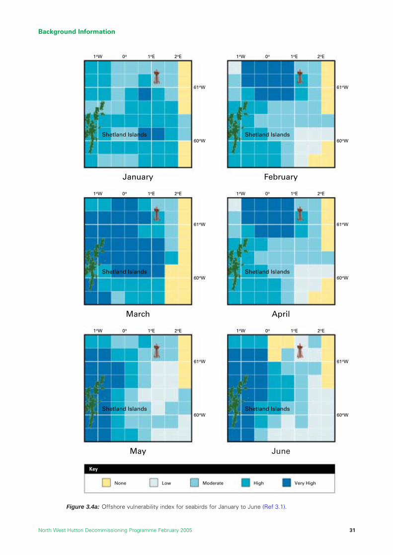
Background Information
North West Hutton Decommissioning Programme February 2005 31
Key
None Low Moderate High Very High
1oW 0o 1oE 2oE
61oW
60oWShetland Islands
1oW 0o 1oE 2oE
61oW
60oWShetland Islands
1oW 0o 1oE 2oE
61oW
60oWShetland Islands
1oW 0o 1oE 2oE
61oW
60oWShetland Islands
1oW 0o 1oE 2oE
61oW
60oWShetland Islands
1oW 0o 1oE 2oE
61oW
60oWShetland Islands
January February
March April
May June
Figure 3.4a: Offshore vulnerability index for seabirds for January to June (Ref 3.1).
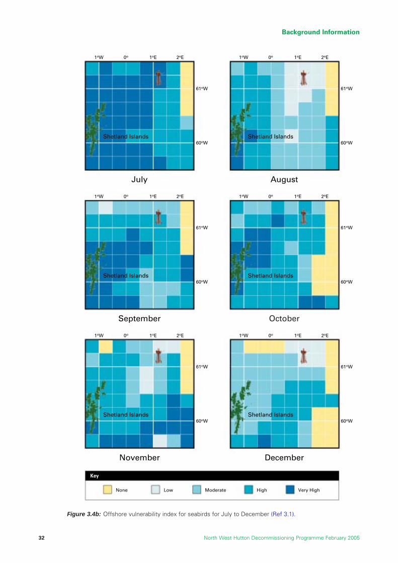
Background Information
North West Hutton Decommissioning Programme February 200532
Key
None Low Moderate High Very High
1oW 0o 1oE 2oE
61oW
60oWShetland Islands
1oW 0o 1oE 2oE
61oW
60oWShetland Islands
1oW 0o 1oE 2oE
61oW
60oWShetland Islands
1oW 0o 1oE 2oE
61oW
60oWShetland Islands
1oW 0o 1oE 2oE
61oW
60oWShetland Islands
1oW 0o 1oE 2oE
61oW
60oWShetland Islands
July August
September October
November December
Figure 3.4b: Offshore vulnerability index for seabirds for July to December (Ref 3.1).

3.7 Conservation Status
3.7.1 Introduction
EC Directive 92/43/EEC (Ref. 3.10) on the Conservation of Natural Habitats and of Wild Flora and Fauna (the“Habitats Directive”) and EC Directive 79/409/EEC (Ref. 3.11) on the Conservation of Wild Birds (the “BirdsDirective”), are the main instruments of the European Union for safeguarding biodiversity. Annexes I and IIrespectively of the Habitats Directive list certain habitat types and species that are in greatest need ofconservation at a European level. The Directive requires the establishment of a European network of importanthigh quality sites (Special Areas of Conservation [SAC]) that will make a significant contribution to conservingthese habitats and species.
In the UK, the Habitats Directive was enacted by the Conservation (Natural Habitats etc.) Regulations 1994(Ref.3.12) and applied to the land, and inshore waters including territorial waters out to 12 nautical miles. Withthe implementation of the Offshore Petroleum Activities (Conservation of Habitats) Regulations in 2001(Ref.3.13), the Habitats Directive was extended to include all waters out to a limit of 200 miles. The UKgovernment is presently identifying candidate SACs in UK offshore waters, and the four Annex I habitats currentlyunder consideration are listed in Table 3.5, along with four Annex II species known to occur in the UKCS.
3.7.2 Annex I Habitats
There are no known naturally occurring Annex I habitats in the immediate vicinity of North West Hutton. Thehabitat “reefs” includes a group called ‘biogenic reefs’ which are extensive hard structures formed by thegrowth of either cold water corals such as Lophelia pertusa, or the colonial polychaete Sabellaria spinulosa.There are no such reefs on the seabed around North West Hutton, but there are numerous colonies ofLophelia growing on the platform legs. The distribution of this species on the platform was surveyed in 2002,and a total of 332 separate colonies were identified, ranging in diameter from 40-110cm (Ref 3.14). Mostcolonies were found on the deeper parts of the jacket, below 220ft.
The presence of Lophelia on North West Hutton is an interesting example of the general phenomenon of“opportunistic colonisation” or “marine fouling”, where seaweeds, and animals such as mussels, anemonesand soft corals, settle and grow on man-made structures at sea. In the 30 years since fixed platforms were firstplaced on the UKCS, much has been learned about the distribution, growth rates and succession of the foulingcommunities that become established offshore. For the drifting spores and larvae of marine plants and animals,platforms offer hard surfaces suitable for colonisation at distant offshore locations where the predominantseabed substratum may be soft sediment such as mud or silty sand. The colonies of Lophelia on North WestHutton are therefore of general scientific interest, but stakeholder consultation has indicated that thesecommunities are not of conservation value because they are opportunistic settlements growing on anintroduced surface that is not representative of the natural seabed in the area.
3.7.3 Annex II Species
At North West Hutton Annex II species which have been sighted include harbour porpoise, small numbers ofwhich have been observed in July (Ref. 3.15) and the common seal. Although there are currently no proposedSACs for harbour porpoise in the UK, the Government is re-examining distribution data for this species in anattempt to find likely areas for SACs. Since harbour porpoise are generally more common in near-shore waters,SACs for this species are likely to be located close to the coast.
Background Information
North West Hutton Decommissioning Programme February 2005 33
Annex I habitats Annex II species
Sandbanks that are slightly covered by seawater all the time Grey sealReefs Common sealSubmarine structures made by naturally leaking gas Bottlenose dolphinSubmerged or partially submerged caves Harbour porpoise
Table 3.5: Four Annex I habitats being considered for SAC status, and the four Annex IIspecies found in the UKCS (Ref. 3.5).

3.8 Onshore Sites for Dismantling and Treatment
It is a general requirement that all equipment decommissioned and removed from offshore installations isreturned to shore for processing and reuse or disposal. No decision has yet been made about which sites oronshore facilities would be used to receive, treat and dispose of material brought back to shore from NorthWest Hutton. For the purposes of preparing the Environmental Assessment, two existing industrial locationswere selected as being representative of possible sites. Teesside, on the east coast of England, is an existingindustrial location which has handled decommissioned structures. Stord, on the west coast of Norway, islocated in a relatively un-developed, non-industrial setting, but nevertheless has been used for receiving anddismantling large platforms. Figure 3.5 shows the location of these two sites in relation to the North WestHutton platform.
There are no particular sensitivities within either site, but both are located close to areas recognised for theirnatural beauty and conservation value with respect to flora, fauna and amenity (Figures 3.6 and 3.7).
Background Information
North West Hutton Decommissioning Programme February 200534
Aberdeen
Bergen
OsloStavanger
North West Hutton
NorthSea
ShetlandIslands
Orkney Islands
FaroeIslands
Teesside
Stord
Figure 3.5: Location map of potential onshore disposalsites for North West Hutton (Ref 3.1).
Seaton Channel
Seaton SandsSeaton Carew
Billingham
Newport Bridge
Middlesbrough
Redcar
Seal Sands
TEES BAY
North GareSouth Gare
Coatham Sands
Transporter Bridge
Stockton-On-Tees
TeesBarrage
Protected Areas
Key:
Figure 3.6: Location map for Tees Estuary andconservation sites in the area (Ref 3.1).
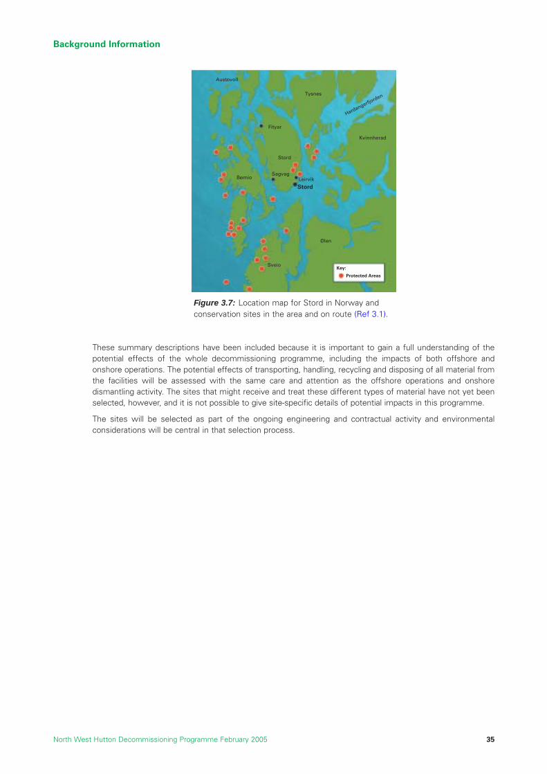
Background Information
North West Hutton Decommissioning Programme February 2005 35
Austovoll
Tysnes
Fityar
Stord
Bomio
Sveio
Olen
Kvinnherad
LeirvikSagvag
Stord
Hardangerfjorden
Protected Areas
Key:
Figure 3.7: Location map for Stord in Norway andconservation sites in the area and on route (Ref 3.1).
These summary descriptions have been included because it is important to gain a full understanding of thepotential effects of the whole decommissioning programme, including the impacts of both offshore andonshore operations. The potential effects of transporting, handling, recycling and disposing of all material fromthe facilities will be assessed with the same care and attention as the offshore operations and onshoredismantling activity. The sites that might receive and treat these different types of material have not yet beenselected, however, and it is not possible to give site-specific details of potential impacts in this programme.
The sites will be selected as part of the ongoing engineering and contractual activity and environmentalconsiderations will be central in that selection process.
References
3.1 “Report ENV 01”, BMT Cordah Ltd, Environmental Statement in support of the De-commissioning ofthe North West Hutton Facilities, Report No. BPX067/ES/2003, June 2004.
3.2 Coull, K. A., Johnstone, R. and Rogers, S.I. (1998). Fisheries Sensitivity Maps in British Waters, UKOOA Ltd.
3.3 Kerr McGee, 2002, Hutton Field De-commissioning Programme
3.4 Adams J. A. (1987), The primary ecological subdivisions of the North Sea: Some aspects of theirplankton communities. In Bailey, R and Parish BB eds. Development in Fisheries in Scotland. FisheriesNews, London 165 – 181 pp.
3.5 “Report ENV05”, BMT Cordah Ltd, Analysis of Samples Collected from Cuttings Pile at North WestHutton by ROV, July 2003. Document No. BPX54/NWH/04, June 2004.
3.6 “Report ENV 08”, BMT Cordah Ltd, Long-term Trends in Seabed Disturbance Around the North WestHutton Platform, Document No. BPX54/NWH/04, 2004.
3.7 Stone, C.J., (2001), Cetacean observations during seismic surveys in 1999, JNCC Report. No. 316http://jncc.gov.uk
3.8 JNCC, (2002), Natura 2000 in UK Offshore Waters: Advice to Support the Implementation of the ECHabitats and Birds Directives in UK Offshore Waters, JNCC Report 325, http://www.jncc.gov.uk
3.9 JNCC, (1999), Seabird vulnerability in UK waters: Block specific vulnerability, 1999. Joint NatureConservation Committee, Aberdeen
3.10 EC Directive 92/43/EEC, 21st May 1992, On the Conservation of Natural Habitats and of Wild Fauna andFlora. Last update 8th July 2003.
3.11 EC Directive 79/409/EEC, 2nd April 1979, On the Conservation of the Wild Birds.
3.12 Statutory Instrument 1994 No. 2716, The Conservation (Natural Habitats etc.) Regulations 1994
3.13 Offshore Petroleum Activities (Conservation of Habitats) Regulations, 2001
3.14 “Report ENV 03”, An evaluation of the Distribution of the Cold-Water Coral “Lophelia pertusa” on NorthWest Hutton. Report No. L3/AB/26(A)/T/QAM/30.4.02/A, 11th March 2004.
3.15 UKDMAP, (1998), United Kingdom Digital Marine Atlas – An atlas of the seas around the British Isles.Software third edition compiled by British Oceanographic Data Centre, Birkenhead.
3.16 UKOOA, Drill Cuttings Initiative Food Chain Effects Literature Review, Report by University of Wales– Bangor, Continental Shelf Associates Inc (UKOOA Drill Cuttings JIP, Phase 2 follow up reports)
Background Information
North West Hutton Decommissioning Programme February 200536

4 DESCRIPTION OF ITEMS TO BE DECOMMISSIONED
4.1 Introduction
The structures and materials included in this decommissioning programme are:
• the North West Hutton platform, which comprises a steel support structure (the jacket), drillingtemplate, and topsides;
• the 10” gas import pipeline from the Ninian tee (PL 147);
• the 20” oil export pipeline to Cormorant Alpha (PL 148);
• the drill cuttings pile on the seabed around the base of the jacket; and
• seabed debris and other items within the vicinity of the platform and pipelines.
This section presents a detailed description of the items to be decommissioned; their location in the NorthWest Hutton field is shown in Figures 3.1 and 3.2 Section 3. Quantitative information about the different typesof material contained in the items is presented in Section 5.
4.2 Description of the North West Hutton Platform
The North West Hutton platform is an integrated oil and gas drilling, production processing andaccommodation facility. It was designed to access reserves of oil and gas, and process these fluids offshoreso that they could be exported safely to land. The main components of the platform are shown in Figures 4.1and 4.4. Information on the size and weight of components is summarised in Tables 4.1, 4.2 and 4.3.
4.2.1 Support Structures
The main support structure, or jacket, is an eight-legged structure, with vertical and horizontal bracing thatprovides its overall structural strength. The jacket was built onshore and the complete unit then transportedto its present location by barge, launched, positioned over the drilling template, and fixed to the seabedusing steel piles.
Each of the four main corner legs has five 60” diameter piles securing it to the seabed. The piles were installedby lowering them through a series of guides which are fixed to the jacket. At the base of the jacket the pilesenter 35m long sleeves called pile-sleeves and are driven into the seabed. The pile sleeves are fixed to thelower part of each corner leg, and the connection between the piles and the sleeves is made by cementing(“grouting”) them in place. These legs and the associated piles and pile sleeves are referred to as “bottles”,and the section of the jacket from the seabed to the top of the bottles and piles, including all the bracing andother equipment, is referred to collectively as the “footings” (Figure 4.2). The footings is that section of thejacket below the highest point of the piles, which are approximately 40 metres above the seabed and the totalweight, including piles and grout, is approximately 9,000 tonnes (Ref. 4.3).
Sacrificial anodes made from an alloy comprising mainly aluminium and zinc (Section 5), protect the jacket andother underwater steel components against corrosion.
A steel module support frame (MSF) is located on top of the jacket to support the footprint area of the topsidesmodules and transfer the topsides weight evenly into the jacket structure. This structure was installedseparately and weighs approximately 1,430 tonnes (Ref. 4.2). Although effectively a part of the jacketstructure, this weight is in addition to the quoted weight of the jacket.
Description of Items to be Decommissioned
North West Hutton Decommissioning Programme February 2005 37

Notes1. The jacket comprises 2 rows of 4 legs. The base is 85.6 x 59.7m, tapering to 47.7 x 21.8m at the top.2. There are five 60” diameter piles at each corner, and they penetrate 55-62m into the seabed .3. The total weight of piles is 5,200 tonnes. The weight secured to the jacket above the seabed is 2,600 tonnes,
including 400 tonnes for grout.4. These items are included in the jacket weight.5. Details of the caissons are shown in Table 4.2.6. Installed mass is 800 tonnes, estimated existing mass 400 tonnes (Ref. 4.5).
Description of Items to be Decommissioned
North West Hutton Decommissioning Programme February 200538
Pile sleeves
Seabed
Piles
Bottle leg
Module SupportFrame
Piles
Corner leg
Pile guides
Footings
Figure 4.1: Computer graphic of the main components of the North West Hutton jacket.
Component Number Dimensions Total Weight (tonnes)
Jacket 1 154m high (1) 14,070Anodes 1,840 3.0m x 0.25m x 0.25m 800 (6)Piles (2) 20 105.5m x 1.54m (60”dia) 2,600 (3)J tubes 6 0.3m (12”) diameter (4)Risers 3 0.26m – 0.51m (10” to 20”) diameter (4)Caissons (5) 12 0.26m – 0.9m (10” to 36”) diameter (4)Total 17,470
Table 4.1: The size and weight of component parts of the North West Hutton jacket. All weights are tonnesdry weight in air (Ref.4.1).

Notes1. This is the depth relative to LAT.
Description of Items to be Decommissioned
North West Hutton Decommissioning Programme February 2005 39
Leg and Pile Clustersincorporating grout
densitometers
Framing Members
Leg A4
Leg A1
Leg B4
Seabed Template
Risers and J-Tubes
Figure 4.2: Computer graphic showing the make up of the North West Huttonjacket footings.
Number Size Function Termination depth (1)
2 32” Firewater lift -17.6 and -16.23 36” Seawater lift -41m1 75” Potable water source -37m1 36” Oil-based drill cuttings -60m1 18” Cooling water disposal +8m1 36” Production -67m2 14” Water-based drill cuttings +6m and +5m1 75” Produced water disposal -15m
Table 4.2: Details of the caissons on North West Hutton (Ref. 4.6)

Description of Items to be Decommissioned
North West Hutton Decommissioning Programme February 200540
Figure 4.3: Photographs showing the size and scale of the North West Hutton jacket.
Pho
togr
aphs
cou
rtes
y of
Cha
rles
Hod
ge, L
owes
toft
, Nor
folk

4.2.2 Topsides
The platform topsides were assembled from a number of individual modules which were lifted into positionby a large floating crane vessel once the jacket had been installed. These cranes are sometimes referred toas “heavy lift vessels” (HLV) or “semi-submersible crane vessels” (SSCV). Each module contains equipmentto provide a specialised function such as oil separation, gas compression, drilling, or accommodation. Themajority of each module was constructed onshore, and then all the necessary process, utility and electricalconnections were completed in an intensive phase offshore known as “hook-up”.
A total of 22 heavy lifts was required to construct the topsides (Ref. 4.4). The relative position of themodules is shown in Figure 4.4 and details of their function and dimensions are given in Table 4.3. Inaddition to the main modules, a significant number of other items necessary for safe and effectiveproduction operations are installed on the topsides, including a flare boom, cranes, two drilling derricks andexhaust towers.
The wells necessary for the production of oil were contained in a series of 40 pipes (referred to as conductors)that protected the wells from the seabed up to the platform at surface. These conductors, which have nowbeen removed, were supported by six guide frames which are an integral part of the jacket.
The pipelines on the seabed are connected to the topsides by steel tubes called risers. Other steel pipes calledcaissons run from the topsides into the sea, and performed a number of functions including the lifting ofseawater for process cooling, fire water, discharge of drill cuttings and other utility functions.
Description of Items to be Decommissioned
North West Hutton Decommissioning Programme February 2005 41
Photograph of North West Hutton topsides.
Pho
togr
aphs
cou
rtes
y of
Cha
rles
Hod
ge, L
owes
toft
, Nor
folk
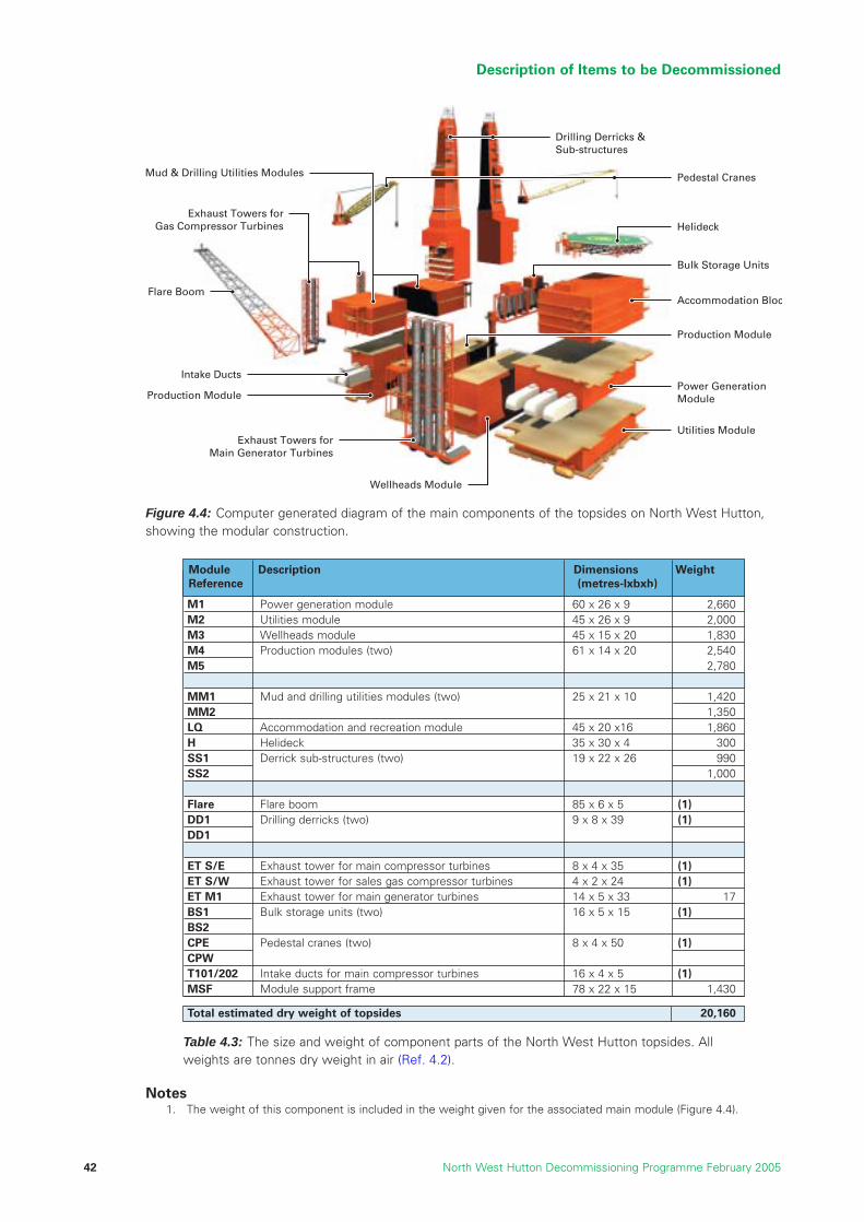
Notes1. The weight of this component is included in the weight given for the associated main module (Figure 4.4).
Description of Items to be Decommissioned
North West Hutton Decommissioning Programme February 200542
Production Module
Intake Ducts
Flare Boom
Exhaust Towers forMain Generator Turbines
Utilities Module
Accommodation Bloc
Pedestal Cranes
Drilling Derricks &Sub-structures
Power GenerationModule
Helideck
Bulk Storage Units
Production Module
Wellheads Module
Exhaust Towers forGas Compressor Turbines
Mud & Drilling Utilities Modules
Figure 4.4: Computer generated diagram of the main components of the topsides on North West Hutton,showing the modular construction.
Table 4.3: The size and weight of component parts of the North West Hutton topsides. Allweights are tonnes dry weight in air (Ref. 4.2).
M1 Power generation module 60 x 26 x 9 2,660M2 Utilities module 45 x 26 x 9 2,000M3 Wellheads module 45 x 15 x 20 1,830M4 Production modules (two) 61 x 14 x 20 2,540M5 2,780
MM1 Mud and drilling utilities modules (two) 25 x 21 x 10 1,420MM2 1,350LQ Accommodation and recreation module 45 x 20 x16 1,860H Helideck 35 x 30 x 4 300SS1 Derrick sub-structures (two) 19 x 22 x 26 990SS2 1,000
Flare Flare boom 85 x 6 x 5 (1)DD1 Drilling derricks (two) 9 x 8 x 39 (1)DD1
ET S/E Exhaust tower for main compressor turbines 8 x 4 x 35 (1)ET S/W Exhaust tower for sales gas compressor turbines 4 x 2 x 24 (1)ET M1 Exhaust tower for main generator turbines 14 x 5 x 33 17BS1 Bulk storage units (two) 16 x 5 x 15 (1)BS2CPE Pedestal cranes (two) 8 x 4 x 50 (1)CPWT101/202 Intake ducts for main compressor turbines 16 x 4 x 5 (1)MSF Module support frame 78 x 22 x 15 1,430
Total estimated dry weight of topsides 20,160
Module Description Dimensions WeightReference (metres-lxbxh)

4.3 Description of the North West Hutton Drilling Template and Wells
A 20 slot drilling template (Ref. 4.1) was installed on the seabed and 7 wells were drilled prior to the installationof the platform. This technique, known as pre-drilling, allows early start-up of production once the platform iscommissioned. The template is of tubular steel construction 12.8m long, 12.2m wide and 3.7m high, andweighs 290 tonnes; it is fixed to the seabed by three 20” diameter piles each approximately 15m long (Figure4.5). For all evaluation purposes in this decommissioning programme, the steel drilling template is consideredto be an integral part of the jacket at the seabed level.
The North West Hutton platform was designed to accommodate a maximum of 40 wells at any one time(referred to as 40 “Slots”). A total of 53 operational wells (including new wells and sidetracks) were drilledinto the reservoir over the life of the field; the last well was drilled in 1992 (Ref. 4.7). The wells were drilledusing a technique known as “directional drilling”, which enabled the entire reservoir to be accessed fromthe platform. There are therefore no subsea wells or subsea production facilities associated with the NorthWest Hutton development.
The wells at North West Hutton are constructed from concentric steel pipes cemented into the wellbore. Theoil and gas from the reservoir were transported safely to the platform for processing by means of steel pipesknown as “production tubing”. In the zone from the seabed to platform the production tubing is housed insidethe conductor pipes, to give it additional protection.
4.4 Description of the North West Hutton Pipelines
There are three separate pipelines (Figure 4.6.) associated with North West Hutton, as follows:
PL 147 A 10” gas pipeline originally used for natural gas export to the FLAGS pipeline system, and latterlyused to import gas for fuel purposes from the Ninian Field. A small section (120m long) of disused10” pipeline at Welgas Tee is also included in this programme.
PL 148 A 20” pipeline used to export crude oil from the North West Hutton platform to the CormorantAlpha platform.
PL 175 A 12” crude oil pipeline used to import oil from the nearby Hutton TLP for onward transportationvia PL 148. The Hutton field has been decommissioned, and this pipeline has been disconnectedfrom North West Hutton at the subsea spool piece.
Description of Items to be Decommissioned
North West Hutton Decommissioning Programme February 2005 43
Figure 4.5: Computer generated diagrams illustrating the design of the North West Hutton drilling template.

The pipeline PL 175, riser and spool piece are owned by the Hutton field partners and its decommissioningwas approved under the Hutton Decommissioning Programme (Ref. 4.13).
It has been agreed that the decommissioning of the PL 175 riser and subsea spool piece at North West Huttonwill be carried out by the North West Hutton owners on behalf of the Hutton owners under the terms of the‘Agreement Relating to the Offtake of Crude Oil from the Hutton and North West Hutton’ (Ref. 4.11), along withthe North West Hutton facilities. The risers on North West Hutton associated with PL 147, PL 148 and PL 175will be decommissioned along with the topsides and support structures. The spool pieces will be left in placebecause they are buried and any exposed ends will be protected. If any section of the jacket is left on theseabed then any corresponding section of the risers will remain attached to the jacket.
The riser associated with PL 148 on Cormorant Alpha will be disconnected and isolated with blind flanges atthe topsides and the bottom of the riser. The riser will be filled with inhibited seawater and monitored toensure its integrity, and will be decommissioned along with Cormorant Alpha topsides and structures, as it ispart of the Brent System and is owned by the Brent owners (Figure 10.8 Section 10).
4.4.1 10” Natural Gas Export / Import Pipeline (PL 147)
The gas pipeline (Figure 4.7) was originally used to export gas to the FLAGS natural gas transportation system.In 1994, it was disconnected from the FLAGS system and connected to the Ninian field gas export line, sothat North West Hutton could import gas for use as fuel. As part of this switch in duty of the pipeline, a 260msection of pipeline was disconnected, made safe and left on the seabed near the original tie-in point of theWestern Leg Gas Pipeline (Cormorant A to Brent). This disused section of line and the associated protectiveequipment is included in the evaluation of the overall decommissioning programme for North West Hutton.
The existing pipeline is constructed from steel with an external protective coating of coal tar epoxy andconcrete, and is protected against corrosion by the use of sacrificial anodes (Ref. 4.8). A 250m long section of6” diameter flexible, composite pipeline was used to make the connection to the Ninian gas system. At adistance of about 260m from the North West Hutton platform a sub-sea isolation valve (SSIV) is incorporatedin the line together with an umbilical that allows the valve to be controlled from the platform. The SSIV wasinstalled as a safety feature to enable the gas from the pipeline to be shut off in an emergency.
Description of Items to be Decommissioned
North West Hutton Decommissioning Programme February 200544
Figure 4.6: Layout of pipelines in the North West Hutton field.

The pipeline was trenched to a depth of 0.45m below the seabed at the time of installation. The line is currentlyburied along approximately 73% of its length (Ref. 4.8) by rock positioned to protect it and also by naturalbackfilling of the trench with seabed sediments. The only areas currently lying proud of the seabed are theconnections to the SSIV, the SSIV itself and the flexible section used for the tie-in to the Ninian pipeline.
The pipeline crosses one other pipeline, the Western Leg Gas Pipeline (Cormorant A to Brent) and thiscrossing is supported and protected by concrete structures known as mattresses.
The pipeline and associated equipment on the seabed have been regularly inspected and fully maintainedsince installation.
A schematic of the gas pipeline PL 147 is shown in Figure 4.7, and the main components of the pipeline arelisted in Table 4.4.
4.4.2 20” Oil Pipeline (PL 148)
The 20”oil pipeline (Figure 4.8) was used to export oil and natural gas liquid (NGL) from the North West Huttonfield and the nearby Hutton field to Cormorant Alpha. From Cormorant Alpha the oil was exported via the Brentsystem to Sullom Voe in the Shetland Islands.
Description of Items to be Decommissioned
North West Hutton Decommissioning Programme February 2005 45
Figure 4.7: North West Hutton 10” gas pipeline PL 147.

The pipeline is constructed of steel with a coal tar and concrete coating, in a similar manner to the gas pipeline(Ref. 4.8). Sacrificial anodes are located along the length of the pipeline to provide protection against corrosion.
The oil pipeline has not been trenched and lies on the seabed. It crosses three other lines listed below andthese crossings are protected with concrete mattresses.
• KP 11.699 – Flow line P1
• KP 11.537 – P1 Control Line
• KP 8.209 – 10” Western Leg Gas Pipeline
A schematic of the oil pipeline PL148 is shown in Figure 4.8, and the main components of the pipeline arelisted in Table 4.4.
The pipeline and associated equipment have been regularly inspected and fully maintained sinceinstallation (Ref. 4.8).
Table 4.4 gives further information on the pipelines, SSIV and control umbilical and the concrete mattressesthat are used to protect some parts of these lines.
Description of Items to be Decommissioned
North West Hutton Decommissioning Programme February 200546
Figure 4.8: North West Hutton 20” oil pipeline PL148.

Notes1. Nominally, there is 0.2 to 0.45m of coverage (soil, rock) above the gas pipe line, which is covered for 73% of its length.2. The whole length of the umbilical is protected by 63 concrete mattresses weighing a total of approximately 230 tonnes.3. The SSIV skid rests in the gas import trench, which is nominally 0.45m deep.4. The steel pipe is protected against corrosion by a 5mm thick coal tar epoxy coating and aluminum bracelet anodes
– 211 on the oil pipeline – 212 on the gas pipeline.5. The whole length of the flexible is protected by 30 mattresses weighing approximately 430 tonnes in total and some
areas are supported by bridges and crossings which have a total weight of approximately 419 tonnes.6. There are no mattresses but a few sand bags.7. The length of the pipeline section is protected by 14 flexible mattresses, weighing approximately 100 tonnes in total.
N/A = Not applicable.
4.5 Description of the North West Hutton Drill Cuttings Pile
The drill cuttings pile is an accumulation on the seabed around the base of the jacket that consistspredominantly of rock “cuttings” from the drilling operations. When wells are drilled a fluid, referred to as“mud”, is circulated into the well to control pressure and remove the small pieces of rock generated by thedrilling operation. During the period of development drilling on North West Hutton between 1982 and 1992,the approved disposal method for these cuttings was to discharge them onto the seabed after cleaning.
It is estimated from drilling records that approximately 28,000m3 (Ref 4.12) of cuttings were discharged atNorth West Hutton prior to the cessation of drilling in 1992. The cuttings were discharged through a caissonat a depth of -60m below sea level for oil-based mud cuttings and +6.0m for water-based mud cuttings. Therelatively low current speeds in the area resulted in the cuttings forming a pile on the seabed around the baseof the platform. The pile presently has a maximum depth of 5.5m in the centre and quickly thins to around 3mand then thins gradually to approximately 1.5m (Ref. 4.10) just beyond the perimeter of the jacket legs. Thepile is elliptical in shape and orientated along a NE/SW axis as a result of the influence of the prevailing currentsin the area. Figure 4.9 shows the latest side-scan sonar image of the cuttings pile at North West Hutton.
Prior to discharge, the cuttings were cleaned to remove excess drilling mud. Because of the nature of the rockand the drilling mud, a small amount of residual mud remained coating the rock and as a result wasincorporated in the cuttings pile.
Description of Items to be Decommissioned
North West Hutton Decommissioning Programme February 2005 47
Weight 5,300 tonnes 2,4
Crossing Rock Dump at
Wellgas Leg
Steel Flexible
Disused Wellgas Tee
Section SSIV Skid
Control Umbilical
Status Not trenched Trenched to 0.45m (1)
Not trenched Trenched to 0.45m
In shallow trench (3)
Resting on seabed (2)
Diameter 20” 10” 6” 10"Length 12.85 km 12.9 km 250.4 m 120m 16.0m x 3.8m x
2.5m400m
Material Carbon Steel (4)
Carbon Steel (4)
Composite steel /
synthetic
Carbon Steel (4)
Steel / Grout fi lled tubulars
Plastic and Steel
Weighting/ Protection
45mm reinforced Concrete
45mm Reinforced Concrete
45mm Concrete
Weight Coat
N/A N/A
00 tonnes 12 tonnes 20 tonnes 90 tonnes 10 tonnesAnodes Yes Yes YesMattresses 300 tonnes None 430 (5) 100 tonnes (7) None (6) 230Bridge/ Minor (5m)
Crossing to
None 419 (5) None None None
Aspect
Pipelines
Oil Export (PL148)
Gas Import (PL147)
Table 4.4: Summary of pipeline equipment.
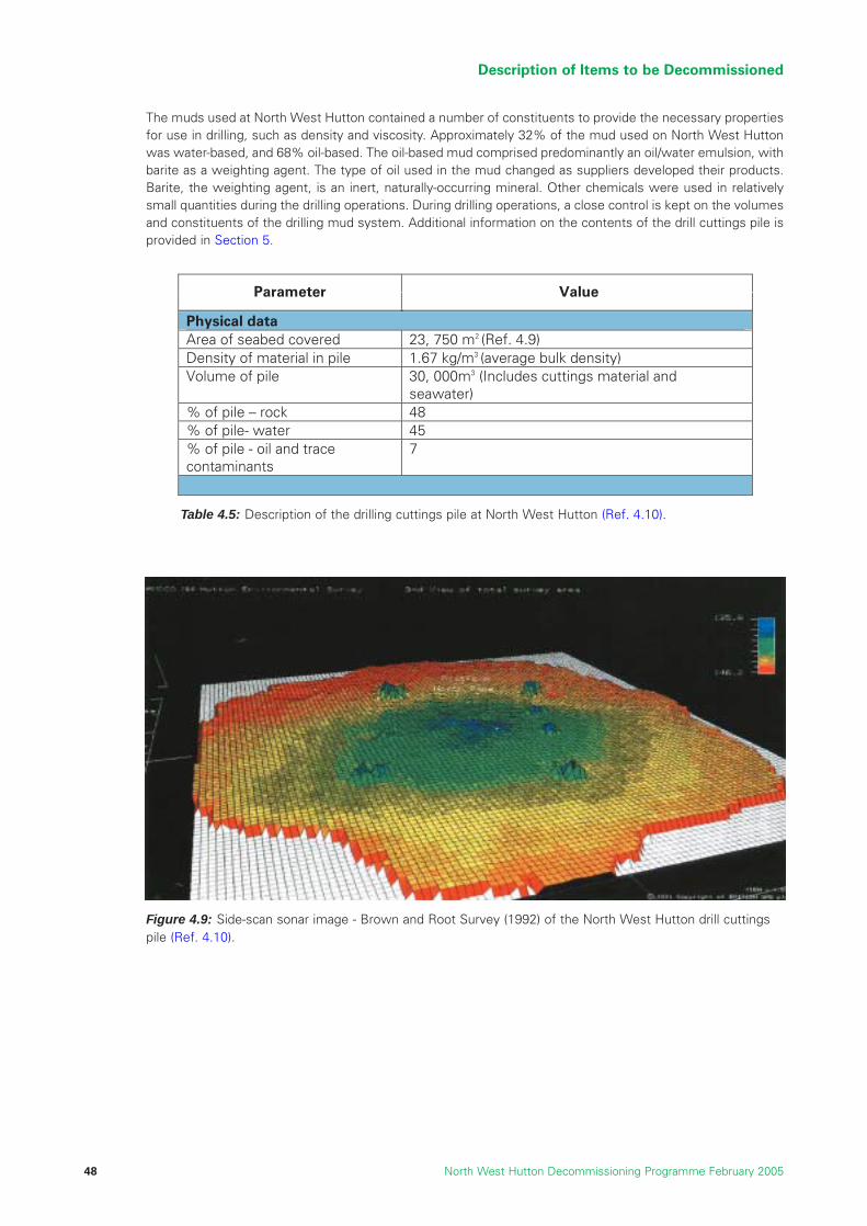
The muds used at North West Hutton contained a number of constituents to provide the necessary propertiesfor use in drilling, such as density and viscosity. Approximately 32% of the mud used on North West Huttonwas water-based, and 68% oil-based. The oil-based mud comprised predominantly an oil/water emulsion, withbarite as a weighting agent. The type of oil used in the mud changed as suppliers developed their products.Barite, the weighting agent, is an inert, naturally-occurring mineral. Other chemicals were used in relativelysmall quantities during the drilling operations. During drilling operations, a close control is kept on the volumesand constituents of the drilling mud system. Additional information on the contents of the drill cuttings pile isprovided in Section 5.
Description of Items to be Decommissioned
North West Hutton Decommissioning Programme February 200548
Value Parameter
Physical data Area of seabed covered 23, 750 m (Ref. 4.9) 2
1Volume of pile 30, 000m3 (Includes cuttings material and
seawater) % of pile – rock 48 % of pile
Density of material in pile .67 kg/m3 (average bulk density)
- water 45 % of pile - oil and trace 7 contaminants
Table 4.5: Description of the drilling cuttings pile at North West Hutton (Ref. 4.10).
Figure 4.9: Side-scan sonar image - Brown and Root Survey (1992) of the North West Hutton drill cuttingspile (Ref. 4.10).

4.6 Debris and Other Material
The cuttings pile directly beneath the platform contains items and material inadvertently lost from theplatform, or from ROVs and divers working subsea. This includes cement, scaffold poles, gratings, toolsand welding rods.
The most recent survey of the natural seabed in the immediate vicinity of the platform shows the presenceof a small number of items which have accumulated over the life of the platform.
The jacket was damaged during installation as the result of a severe storm. This damage included areas aroundthe pile sleeves and pile grouting system. As a result, a total of about 100 tonnes of grout was spilled ontothe seabed around the four main legs, particularly at leg B1.
An inspection survey of the routes of PL 147 and PL 148, carried out in 2001, showed that there wererelatively minor amounts of debris along these pipelines.
Description of Items to be Decommissioned
North West Hutton Decommissioning Programme February 2005 49

References
4.1 “Report TEC 05”, AKER KVAERNER, North West Hutton, Jacket Information Package, Document No.8226-NWH-ST-004, 13th May 2003.
4.2 North West Hutton Technical Datapack, Document No. EOS-NWHD-BPA-FAC-DSB-001 Rev A, 22nd
November 1999.
4.3 Weight Estimated by BP based on Heerema Marine Contractor’s Drawing No. HR-126-00-1, Rev A, 15th
October 1999, Removal Sequence North West Hutton Jacket and Footing.
4.4 HEEREMA Marine Contractors, North West Hutton, Platform Removal Feasibility Study, Document No.E/1018 (2205), Rev 2, 29th October 1999.
4.5 “Report TEC 01”, CORRPRO Companies Europe Ltd, North West Hutton, Life Assessment of JacketFootings, 19th September 2003.
4.6 WS Atkins Oil and Gas, North West Hutton, Appurtenance Arrangement (Sheet 4 of 5), Drawing No.NWH-APD4, dated January 1999.
4.7 North West Hutton Cessation of Production Application, Rev. 4, July 1999.
4.8 “Report TEC 14–18”, JP Kenny, North West Hutton, Pipeline Decommissioning – Technical SummaryReport, Rev 03, 21st November 2003.
4.9 “Report TEC 11/12”, Technical Review of the Options of Covering, Relocation, CAD, and Recovery forOnshore Treatment of the North West Hutton Drill Cuttings Pile, Report 296.UK.0303.1 (Rev.0), June2003.
4.10 Brown and Root Survey (1992), North West Hutton Drill Cuttings Report, Document No. M70381(0753R)160293, Rev 1,16th February 1993.
4.11 Agreement Relating the Offtake of the Crude Oil from the Hutton and North West Hutton Fields.Conformed copy including Amendments Effected by Amendments No. 1, 11th October 1984.
4.12 “Report ENV 08”, BMT Cordah Ltd, Long-term Trends in Seabed Disturbance Around the North WestHutton Platform, Document No. BPX54/NWH/04, 2004.
4.13 Kerr McGee, 2002, Hutton Field De-commissioning Programme.
Description of Items to be Decommissioned
North West Hutton Decommissioning Programme February 200550
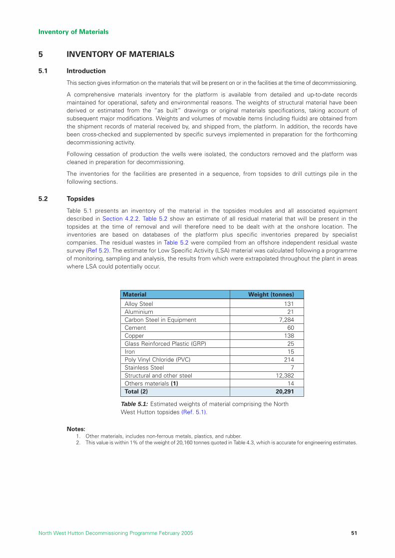
5 INVENTORY OF MATERIALS
5.1 Introduction
This section gives information on the materials that will be present on or in the facilities at the time of decommissioning.
A comprehensive materials inventory for the platform is available from detailed and up-to-date recordsmaintained for operational, safety and environmental reasons. The weights of structural material have beenderived or estimated from the “as built” drawings or original materials specifications, taking account ofsubsequent major modifications. Weights and volumes of movable items (including fluids) are obtained fromthe shipment records of material received by, and shipped from, the platform. In addition, the records havebeen cross-checked and supplemented by specific surveys implemented in preparation for the forthcomingdecommissioning activity.
Following cessation of production the wells were isolated, the conductors removed and the platform wascleaned in preparation for decommissioning.
The inventories for the facilities are presented in a sequence, from topsides to drill cuttings pile in thefollowing sections.
5.2 Topsides
Table 5.1 presents an inventory of the material in the topsides modules and all associated equipmentdescribed in Section 4.2.2. Table 5.2 show an estimate of all residual material that will be present in thetopsides at the time of removal and will therefore need to be dealt with at the onshore location. Theinventories are based on databases of the platform plus specific inventories prepared by specialistcompanies. The residual wastes in Table 5.2 were compiled from an offshore independent residual wastesurvey (Ref 5.2). The estimate for Low Specific Activity (LSA) material was calculated following a programmeof monitoring, sampling and analysis, the results from which were extrapolated throughout the plant in areaswhere LSA could potentially occur.
Notes:1. Other materials, includes non-ferrous metals, plastics, and rubber. 2. This value is within 1% of the weight of 20,160 tonnes quoted in Table 4.3, which is accurate for engineering estimates.
Inventory of Materials
North West Hutton Decommissioning Programme February 2005 51
Table 5.1: Estimated weights of material comprising the NorthWest Hutton topsides (Ref. 5.1).
Material Weight (tonnes)
Alloy Steel 131Aluminium 21Carbon Steel in Equipment 7,284Cement 60Copper 138Glass Reinforced Plastic (GRP) 25Iron 15Poly Vinyl Chloride (PVC) 214Stainless Steel 7Structural and other steel 12,382Others materials (1) 14Total (2) 20,291
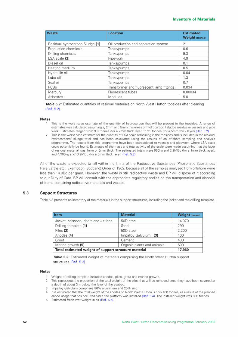
Notes1. This is the worst-case estimate of the quantity of hydrocarbon that will be present in the topsides. A range of
estimates was calculated assuming a, 2mm and 5mm thickness of hydrocarbon / sludge residue in vessels and pipework. Estimates ranged from 9.8 tonnes (for a 2mm thick layer) to 21 tonnes (for a 5mm thick layer) (Ref. 5.2).
2 This is the worst-case estimate for the quantity of LSA scale remaining in the topsides and is included in the residualhydrocarbons/ sludge total and has been calculated using the results of an offshore sampling and analysisprogramme. The results from this programme have been extrapolated to vessels and pipework where LSA scalecould potentially be found. Estimates of the mass and total activity of the scale were made assuming that the layerof residual material was 1mm or 5mm thick. The estimated totals were 960kg and 2.2MBq (for a 1mm thick layer),and 4,900kg and13.9MBq (for a 5mm thick layer) (Ref. 5.2).
All of the waste is expected to fall within the limits of the Radioactive Substances (Phosphatic SubstancesRare Earths etc.) Exemption (Scotland) Order of 1962, because all of the samples analysed from offshore wereless than 14.8Bq per gram. However, the waste is still radioactive waste and BP will dispose of it accordingto our Duty of Care. BP will consult with the appropriate regulatory bodies on the transportation and disposalof items containing radioactive materials and wastes.
5.3 Support Structures
Table 5.3 presents an inventory of the materials in the support structures, including the jacket and the drilling template.
Notes1 Weight of drilling template includes anodes, piles, grout and marine growth.2. This represents the proportion of the total weight of the piles that will be removed once they have been severed at
a depth of about 3m below the level of the seabed.3. Impalloy Galvulum comprises 80% aluminium and 20% zinc.4. It is estimated that the total weight of the anodes on North West Hutton is now 400 tonnes, as a result of the planned
anode usage that has occurred since the platform was installed (Ref. 5.4). The installed weight was 800 tonnes.5. Estimated fresh wet weight in air (Ref. 5.5).
Inventory of Materials
North West Hutton Decommissioning Programme February 200552
Waste Location Estimated Weight (tonnes)
Residual hydrocarbon Sludge (1) Oil production and separation system 21Production chemicals Tanks/pumps 0.6Drilling chemicals Tanks/pumps 9.3LSA scale (2) Pipework 4.9Diesel oil Tanks/pumps 0.1Heating medium Tanks/pumps 0.5Hydraulic oil Tanks/pumps 0.04Lube oil Tanks/pumps 1.3Seal oil Tanks/pumps 0.7PCBs Transformer and fluorescent lamp fittings 0.034Mercury Fluorescent tubes 0.00034Asbestos Modules 5.0
Table 5.2: Estimated quantities of residual materials on North West Hutton topsides after cleaning(Ref. 5.2).
Item Material Weight (tonnes)
Jacket, caissons, risers and J-tubes 50D steel 14,070Drilling template (1) Steel 290Piles (2) 50D steel 2,200Anodes (4) Impalloy Galvulum I (3) 400Grout Cement 400Marine growth (5) Organic plants and animals 600Total estimated weight of support structure material 17,960
Table 5.3: Estimated weight of materials comprising the North West Hutton supportstructures (Ref. 5.3).

5.3.1 Grout Densitometers
Grout densitometers are attached to the five pile sleeves on the bottle legs near the underside of the pileguide frame at a depth of approximately 115m. There are 20 densitometers each with two Caesium 137sources i.e. 40 sources in total. The Scottish Environment Protection Agency (SEPA) has indicated that theywould expect the grout densitometer sources to be removed.
Due to the nature of the radioactive sources, it will be safer to remove the sources as a subsea activity ratherthan on the surface. The sources can be removed using a Remotely Operated Vehicle (ROV) then placed intocontainers, prior to being lifted to the surface. This subsea operation will be undertaken by ROVs and notdivers, and therefore there is no risk that people will be exposed to radioactivity. The removal of thedensitometer sources will not cause any drill cuttings pile disturbance. Once on the surface the containersholding the sources will be returned to the appropriate authority for disposal.
The Grout Densitometer sources will be disposed of within the UK, through licensed disposal companies, inaccordance with local environmental requirements and legislation, to the approval of the appropriate authority.
5.4 Well-Related Material
Table 5.4 lists the material from the North West Hutton wells that has already been removed in preparationfor decommissioning. All material has been taken to shore for recycling or re-use.
Note
1. Estimated weight from well programmes.
5.5 Pipelines
Table 5.5 presents an inventory of the materials in the pipelines PL 147 and PL 148. Both the pipelines havebeen cleaned and filled with seawater in preparation for decommissioning.
Inventory of Materials
North West Hutton Decommissioning Programme February 2005 53
Item Material Weight (tonnes)
Conductors and casing Steel (1) 5,200Cement 1,720
Tubing and other equipment Steel 350Wellheads/Xmas trees Steel 200Total estimated weight removed from wells 7,470
Table 5.4: Weight of materials removed from the North West Huttonwells in preparation for decommissioning.
Table 5.5: Estimated weight of materials in the North West Hutton pipelines (Ref. 5.6).
Item Material Weight (tonnes)
Steel 3,679Concrete coating and steel reinforcing bars 3,638
Pipelines Coal tar enamel coating 215Galvalum III anodes 50LSA scale and hydrocarbons N/A
Mattresses and bridges Concrete 1,368Flexible line Steel 12
Composite materials N/ASSIV skid Steel 31SSIV umbilical Composite materials 10
Concrete and reinforcing bar 12Redundant FLAGS tie-in spool Steel 10
Coal tar enamel coating 0.6Galvalum III anodes 0.2
Total estimated weight of pipeline associated material 9,025.8

5.6 Drill Cuttings Pile
Table 5.6 presents an inventory of the material in the drill cuttings pile. The volumes are close approximationsbased on a detailed review of the drilling records and analysis of numerous samples that have been collectedfrom the pile itself. It should be noted that sampling the pile from within the confines of the jacket has beenlimited due to the difficulty of accessing this complex area.
5.7 Debris and Other Seabed Items
Despite careful planning and management of offshore operations small items of equipment can be accidentallydropped into the sea and fall to the seabed. Additional items such as cables and chains can be lost duringmarine activities. Such items identified during the decommissioning activities and post decommissioningsurvey will be removed.
5.8 Onshore Treatment and Disposal of Materials
All waste materials generated in the process of decommissioning North West Hutton and its facilities will betreated or disposed of by licensed contractors at licensed sites with all the necessary permits and consents.The contractors will be chosen through an extensive selection process, where environmental and safetyconsiderations will be paramount, and the social impacts of onshore activities will be assessed.
BP’s duty of care extends beyond the quayside and we will work with the onshore licensed disposal sites andwill ensure that all dismantling and waste treatment and disposal is carried out in a responsible manner. Theprinciples of the waste hierarchy will be applied, in that material will be re-used and recycled whereverpossible in preference to being disposed of.
Upon completion of the onshore treatment and disposal of North West Hutton and its facilities data will beavailable on the quantities of waste recycled and disposed of, and the methods and sites used to disposeof hazardous wastes.
Procurement decisions may result in some or all of the platform and its facilities being delivered overseas foronshore disposal. Trans-frontier Shipment of Waste Regulations 1994 would apply to all materials or wastedelivered overseas for the purposes of recovery or disposal. In this event, prior notification will be given to theCompetent Authorities, before commencement of decommissioning activities.
Inventory of Materials
North West Hutton Decommissioning Programme February 200554
Containment Average Worst CaseTotal Oil (tonnes) (%) (tonnes) (%)
Total Oil 2,605 5.1 3,651 7.2Diesel 521 1 731 1.4Low Toxicity Oil 2,085 4.1 2,922 5.7
PAH 39.4 0.08 41.1 0.08
Nonyl Phenol 2 0.004 3.6 0.08
Ba 5,143 10.1Zn 29.8 0.06Ph 8.7 0.02
PCB 0.004 <0.00001 0.009 <0.00002
Table 5.6: Estimate of total hydrocarbon and contaminant loading in the North West Hutton drillcuttings pile (Ref. 5.5).

References
5.1 North West Hutton Technical Datapack, Document No. EOS-NWHD-BPA-FAC-DSB-001 Rev A, 22nd November 1999.
5.2 Lloyd’s Register, North West Hutton Decommissioning Residual Waste Survey, Reference0391215/R/004, May 2004.
5.3 “Report TEC 05”, AKER KVAERNER, North West Hutton, Jacket Information Package, Document No.8226-NWH-ST-004, 13th May 2003.
5.4 “Report TEC 01” Corrpro Companies Europe Ltd, North West Hutton, Life Assessment of JacketFootings, Rev 0, 19th September 2003.
5.5 “Report ENV 01”, BMT Cordah Ltd, Environmental Statement in support of the De-commissioning ofthe North West Hutton Facilities, Report No. BPX067/ES/2003, June 2004.
5.6 “Report TEC 14 - 18” J P Kenny, Pipeline Decommissioning Technical Summary Report, Document No.05 2416 01 G 3 011, Rev 03, 21st November 2003.
Inventory of Materials
North West Hutton Decommissioning Programme February 2005 55

Inventory of Materials
North West Hutton Decommissioning Programme February 200556
6 GUIDING PRINCIPLES AND SCREENING PROCESS
6.1 Introduction
The responsible decommissioning of disused oil and gas facilities is integral to the exploration and productionbusiness lifecycle ensuring that the process of decommissioning the North West Hutton facilities achieves abalance of the highest, safety, environmental, societal, technical and financial standards, is the basis of allremoval and disposal activities.
This section sets out the guiding principles upon which all the evaluations and recommendations for theeffective decommissioning of the North West Hutton facilities are based. It provides a description of how thescreening of the decommissioning options for each of the facilities was carried out and how the short-list fordetailed evaluation was compiled.
6.2 Guiding Principles
The decommissioning of disused offshore installations is governed under UK law by the Petroleum Act 1998(Ref.6.1) The UK also adheres to the 1992 Oslo and Paris (OSPAR) Convention (Ref.6.2) for the protection ofthe Marine Environment of the North East Atlantic. Specific agreement on the decommissioning of offshoreinstallations is set out in OSPAR Decision 98/3 (Ref.6.3) as agreed at a ministerial meeting of the OSPARCommission in July 1998 in Sintra, Portugal.
Under the OSPAR Convention, there is a presumption that all installations will be completely removed to bere-used, recycled or disposed of on land. Decision 98/3 states that ‘the dumping, and leaving wholly or partlyin place, of disused offshore installations within the maritime area is prohibited’. A base case of total removalmust therefore form the starting point of all evaluations and assessments for the decommissioning of theNorth West Hutton facilities. However, OSPAR Decision 98/3 allows a potential “derogation” (an exemptionfrom the general presumption of total removal) for all or part of the “footings” of steel installations weighingmore than ten thousand tonnes, placed in the maritime area before 9th February 1999.
The DTI’s Decommissioning Guidance Notes (Ref.6.4) state that the decommissioning programme should beconsistent with international obligations and take into consideration:
• the precautionary principle
• best available techniques and best environmental practice
• waste hierarchy principles
• other users of the sea
• health and safety law
• proportionality
• cost effectiveness
Of particular importance is the waste hierarchy principle which is a key element in Decision 98/3. Theconceptual framework, which translates sustainability into practice, advocates that the management of wasteshould follow the “reduce, reuse, recycle and dispose” principle. This framework forms the core of the NorthWest Hutton decommissioning waste management strategy.
In addition to the legislation and general principles outlined above, the business values and policies of theNorth West Hutton owners will underpin the process of preparing for decommissioning, particularly withregard to five key assessment factors or criteria: safety; environmental issues, societal impact, technicalfeasibility, and financial management.
These guiding principles informed the process by which the North West Hutton owners identified andassessed all decommissioning options, in order to balance all the factors and seek to meet the needs of allstakeholders wherever possible.
Guiding Principles and Screening Process
North West Hutton Decommissioning Programme February 2005 57

6.3 Assessment Methodology
The North West Hutton owners have developed and implemented a robust assessment methodology, in orderto determine the best decommissioning option for each of the North West Hutton facilities.
The methodology includes the assessment of the advantages and disadvantages of each option in relation tothe five key criteria. A thorough understanding of the “performance” of the options in each of the criteria, andthe risks or benefits they impart, is therefore necessary to provide the information upon which an objectivecomparative assessment of the decommissioning options can be made.
The owners of North West Hutton have adopted a long-term and comprehensive approach to studying thedecommissioning requirements of the field. This is demonstrated by the range of studies implemented over anumber of years including work specific to the North West Hutton installation and also participation in joint projectswithin industry and academic institutions. All these studies and projects are listed in Section 20 Appendix.
The major effort to study removal of the platform in detail commenced in 1999 although various studies relatingto decommissioning have been ongoing since the early 1990s. A wide range of studies implemented by avariety of contractors, consultants and other specialists has resulted in the recommendations contained in thisdocument. The range of studies completed can be categorised as follows:
Studies to Identify Alternatives to Decommissioning
The purpose of these studies was to determine if there were further uses for the platform, either at its presentlocation or at other locations. This would eliminate the need to dismantle and recycle or dispose of thematerial, and would align with the intent of the waste hierarchy.
Removal Studies
This series of studies set out to examine all the issues associated with the full removal of the North WestHutton platform and all associated material to achieve a clear seabed.
Research Projects
A series of joint industry projects to better define and understand some areas of decommissioning universallyacknowledged as problematic and of particular direct relevance to North West Hutton.
Comparative Assessment Studies
A series of specific studies aimed at clearly describing and comparing the alternative options for the NorthWest Hutton platform facilities in line with the requirements of the Petroleum Act (1998) and where applicable,OSPAR decision 98/3.
In order to ensure that the findings of these studies were independent and objective, the North West Huttonowners invited an international group of scientists and engineers to review all the studies. The IndependentReview Group (IRG) was asked to assess each of the studies for adequacy of scope, clarity, completeness,methodology, relevance and objectivity of conclusions. The final report on the IRG’s findings (Ref.6.5) isavailable as a reference document for this decommissioning programme (Section 20 Appendix).
The North West Hutton owners recognise that a purely scientific assessment of the impacts and risks will notreflect the views of all stakeholders, particularly when the different risks and benefits are valued differently bydifferent stakeholder groups. Although a numerical evaluation model was suggested at the outset as apossible process for balancing the different factors, it was decided after consultation with stakeholders thatthe issues were too complex to be reduced to numerical weightings. An ongoing consultation process withstakeholders was agreed as a more valuable and effective way of reaching a balanced solution for thedecommissioning of North West Hutton.
Taking account of societal aspects is therefore an essential part of the process of evaluating how to balancedifferent factors in building the best decommissioning solution. An integrated stakeholder consultation process hasbeen an invaluable part of the comparative assessment of the decommissioning options for each of the NorthWest Hutton facilities.
Guiding Principles and Screening Process
North West Hutton Decommissioning Programme February 200558
6.4 Comparative Assessment Criteria
A common understanding of each of the comparative assessment criteria is essential, and this sectiondescribes how they were defined and assessed. Each of the criteria requires a specific approach to ensure theappropriate consideration of relevant factors is achieved for each aspect of the programme. The fiveassessment criteria are:
• safety
• environmental impact
• social impact
• technical feasibility
• financial management
6.4.1 Safety
Identifying and quantifying the major safety risks to all personnel involved in the decommissioning operationsis a major part of the comparative assessment.
The safety of all workers involved in the decommissioning activities, both onshore and offshore, is a prioritywhen assessing whether to carry out a particular operation. To this end, the safety case regulations requirethat an ‘Abandonment Safety Case’ (Ref. 6.20) be prepared prior to any decommissioning activities associatedwith platform removal taking place. The Duty Holder, by means of the Safety Case, must demonstrate that theproposed arrangements for decommissioning of the installation reduce the risks to people to the lowest levelthat is reasonably practicable (Ref. 6.7).
Furthermore, legislation requires the Duty Holder to reduce the risks to personnel to as low as reasonablypracticable (ALARP) The Guidance on ALARP (Ref. 6.8) sets out a ‘tolerability of risk’ framework whichconsists of three regions of risk:
• A region of high risk – unacceptable region (considered unacceptable whatever the level of benefitassociated with the activity).
• A region of intermediate risk – tolerable region (region where people are prepared to tolerate the riskto secure the benefits).
• A region of low risk – broadly acceptable region (risks in this area are generally regarded as insignificantand adequately controlled).
A core part of the assessment process is the identification of all hazards associated with the decommissioningwork, an assessment of the associated risk and whether the level of risk is acceptable. One method of evaluatingrisk is through the use of quantitative risk assessment (QRA) techniques which provide a numerical evaluation ofthe risks. The numerical estimations are expressed in terms of Potential Loss of Life (PLL) which estimates thecollective risk to all workers exposed by the Project Activities, and individual risk per annum (IRPA) whichestimates the likelihood of an individual becoming a fatality in any one year while exposed to project activities.
PLL and IRPA are directly related in terms of the number of people and the time spent on the project activities.
PLL = IRPA x Number of people working on the projectFraction of time working per year
In terms of risk acceptability, the requirement is on duty holders to set their own criteria for the acceptabilityand tolerability of risk. However, the HSE commonly define the maximum tolerable level of individual risk offatality as 1 in 1,000 per year, and for the broadly acceptable level of individual risk to be set in the range 1 in100,000 to 1 in 1 million per year. For comparison, the risks of fatality in the manufacturing and agricultureindustries are 1:77,000 and 1:17,000 respectively.
The 1 in 1,000 fatality per year means that there would be 1 fatality in every 1,000 man-years of work, e.g.100 men working for 10 years or 1,000 men working for 1 year.
Guiding Principles and Screening Process
North West Hutton Decommissioning Programme February 2005 59
The QRA has been undertaken using established techniques to provide an estimate of removal and disposalrisks. The technique utilises relevant historical accident data, and is based on the assumption that thesestatistical trends will be repeated for similar work or activities in the future. The data used has been examinedto determine whether more recent safety management practices may have reduced the potential accidentrates. For example, the most recent statistics on diving accidents have not yet been published; the availabledata may reflect unsafe practices no longer utilised in the diving industry. The use of this, and other data wassubsequently factored to recognise the development of safety management systems in recent years andhence are believed to include appropriate levels of risk mitigation.
Where accident data is not available, or is deemed to be irrelevant to decommissioning activities, the accident-initiating events are estimated by the use of event tree analysis which accounts for available preventative andmitigation measures. For example, the potential for dropped objects falling from the jacket has to be estimatedas there is little historical data. On its own, however, a dropped object may not necessarily result in an injuryto personnel; the potential for injury is dependent on the presence of individuals below the dropped object.This risk estimation approach assumes the implementation of Safety Management Systems and riskmitigation measures but also recognises that failures do occur in such systems and this has been estimatedin the analysis.
At this stage in the evaluation, BP believe that the approach taken along with the careful analysis of availabledata has resulted in a risk picture which, including for the provision of mitigation measures and SafetyManagement Systems provides a credible risk model for decommissioning of the North West Hutton platform.However, as engineering and safety management systems are developed for the chosen option the ALARPprinciple will be applied to mitigate the risk to personnel.
The amount of reliance placed on QRA in a decision-making process will depend upon any assumptions whichhave been made, the complexity of the events being modelled and the associated degree of uncertainty.Although numerical values can help with the calculations of safety risk, decisions about human lives at riskcannot be reduced to numbers alone. When there is a great deal of uncertainty associated with a proposedactivity other factors, such as engineering, operational and qualitative analysis, must also be taken intoaccount. This is the situation with the decommissioning of large fixed steel structures due to the lack ofindustry experience.
6.4.2 Environmental Impact
Evaluating the impact of all decommissioning activities on the offshore and onshore environment is a key partof the comparative assessment. A systematic Environmental Impact Assessment (EIA) (Ref. 6.19) (Summaryof EIA Section 19) was undertaken and this provided a clear understanding of the effects of decommissioningthe facilities on the environment. Measures have been developed in line with best industry practice in orderto mitigate where possible, or reduce and remedy any impacts that are unavoidable.
The Environmental Impact Assessment evaluates the overall impact of the decommissioning activities on:
• marine flora and fauna
• energy consumption
• all emissions to the atmosphere both onshore and offshore
• the impact on other users of the sea as well as the impact on onshore amenities
The assessment process is based on recognised techniques and standard methodologies for evaluating theenvironmental impacts from the various operations and tasks under evaluation. The assessment alsoconsiders the availability of, and benefit derived from, potential mitigating measures. The assessment takesinto account the volume, nature, location and impacts caused by all the material and waste associated withthe operations being assessed.
6.4.3 Social Impact
The comparative assessment has attempted to measure the impact on society of all decommissioningactivities and potential options. The most significant areas assessed have been the economic impact (asmeasured by the employment created and income generated from different activities), and the impact onother sea users, primarily the commercial fishing industry. Included under economic impact is the issue of howthe North West Hutton owners will be able to offset decommissioning costs against tax. Although this can beseen as a negative impact on society, a loss of tax revenue for the Government with the potential for impacting
Guiding Principles and Screening Process
North West Hutton Decommissioning Programme February 200560
public spending, it is also a fact that the decommissioning expenditure will generate tax benefits in other areassuch as income tax, so that the actual net impact is difficult to quantify. There has also been an effort to takeinto account society’s views and concerns through a stakeholder engagement process.
The participation of representative groups from society in the consultation process is very important and asmany different organisations and individuals as possible have been invited to take part. The process wasdesigned to highlight conflicting concerns, and priorities that must be taken into account. Various stakeholderengagement processes are being utilised including: workshops, face-to-face meetings, writtencorrespondence and an interactive web-site.
6.4.4 Technical Feasibility
Collecting baseline technical data is the starting point for assessing the feasibility of all engineering activities.Technical studies have been commissioned from a number of reputable experts and companies in order toassess every aspect of decommissioning the North West Hutton facilities.
Since there is little experience of decommissioning large fixed steel structures, and none for structures of thissize and complexity, the assessment of the technical feasibility of different decommissioning activities isbased on existing industry experience and available equipment.
Consideration has been given to new decommissioning technologies, and the North West Hutton ownershave participated in joint industry projects (Ref.6.6) assessing the development of new decommissioningtechnologies. None of these systems is, however, currently available, but this does not preclude newtechnologies being developed in the future.
There are many uncertainties associated with the operations due mainly to the nature of offshore work, thestructural condition of the facility, and the lack of industry experience of carrying out these operations on sucha large scale. QRA techniques, engineering and operational analysis have been used in combination to providecomprehensive robust quantitative and qualitative assessments of each option. These were then used in thedecision-making process for the selection of optimal technical solutions. Technical feasibility and risk cannotbe assessed in isolation but must always consider the implications for the safety risk to workers, potentialimpact on the environment, risk to other users of the sea, and the overall costs.
Technical feasibility and risk were evaluated by examining individual tasks and overall procedures in detail. Thefeasibility of activities, operations or options, and their associated technical risks were assessed by evaluatinga number of key issues including: the availability of equipment; the complexity of operations; the level ofindustry experience relating to the operation; the likelihood that a major failure would occur; and theimplications for the option if a failure were to occur.
Two of these issues are of particular importance when evaluating the feasibility and risk of decommissioningoperations. If an operation can be carried out using existing equipment for which there is a record ofapplication, this will generally result in a significantly lower technical risk for the decommissioning programmethan that associated with the requirement to develop new equipment or procedures. The ability to evaluatesimilar operations enables a significantly greater level of certainty to be applied to an outcome than is the casefor an operation that has never been attempted before.
The risks and implications of operational failure are key factors in evaluating technical risk. This is particularlyrelevant where failure during an operation brings a significant increase in risk as a result of the need toundertake additional activities in an attempt to rectify the situation.
6.4.5 Costs and Financial Management
The costs for decommissioning North West Hutton have been determined from a range of studies looking indetail at all aspects of the work programme. Cost estimates have been subjected to detailed scrutiny basedon input from specialist contractors, comparison with industry norms and incorporation of data from previousdecommissioning activity.
The estimated costs for undertaking particular decommissioning options on the North West Hutton facilitiesare presented as a range of possible costs; this range provides an indication of the level of uncertaintyassociated with the particular option. These estimates are the best that can be obtained and were compiledon the basis of industry knowledge of the planning, operations, procedures and contingencies required foractivities such as decommissioning, and on the unit costs of equipment, plant and personnel. All the estimatesare subject to significant uncertainty due to the lack of direct experience of similar decommissioning projects.
Guiding Principles and Screening Process
North West Hutton Decommissioning Programme February 2005 61

6.5 Method for High Level Option Selection
Complicated modelling and analytical techniques to combine the five criteria were not deemed to be applicablefor determining the recommended decommissioning option (see Section 6.3). Modelling and other techniqueswere, however, applied in some of the individual studies.
A wide range of potential decommissioning options was evaluated and a short list of options selected for moredetailed study. The performance of each option in each of the five assessment criteria was assigned to oneof three qualitative levels of acceptability as defined in Table 6.1.
6.6 Results of High Level Option Selection
This section sets out the decommissioning options for each of the North West Hutton facilities and identifiesthe options short-listed for the comparative assessment. The areas highlighted in blue for each of the facilitiesindicate the options that have been short-listed for further detailed examination. Each of these options is thenevaluated in detail by the agreed criteria in Sections 8, 9 and 10 of this document.
6.6.1 Reuse of the Installation.
In accordance with the waste hierarchy principles, one of the first decommissioning options the North WestHutton owners considered was the reuse of the platform as a whole along with its associated facilities, eitherin the oil and gas industry, or as a ‘new use’ in-situ or at a new location.
Disused offshore facilities are successfully reused in other parts of the world but typically this option is onlyapplicable for a relatively small number of smaller standard structures. The concept is relatively new in theNorth Sea where structures similar to North West Hutton are generally built for the specific requirements ofthe field they service. Several studies have been carried out by companies operating in the North Seaassessing the opportunities for reuse within the industry and for ‘new use’ potential. The following discussionbriefly reviews the possibilities for North West Hutton.
Guiding Principles and Screening Process
North West Hutton Decommissioning Programme February 200562
Table 6.1: Risk Factors and acceptability levels.
Risk Factors Nature ofAssessment Acceptable Marginal Unacceptable
Level of Acceptability
Safety ofpersonnel
Impacts on theenvironment
Impacts on society
Technical
Economic
MainlyQuantitative
Quantitative/Qualitative
MainlyQualitative
MainlyQualitative
Quantitative
A region of low risk –broadly acceptableregion risks in thisarea are generallyregarded asinsignificant andadequately controlled.IRPA is well withinthe recognisedthreshold of 1 in 1000
The proposedoperations mayprovide a benefit, nochange or at worstnegligibleenvironmentalimpacts
There are tangiblepositive benefits orpossibly nodiscernible negativeimpacts
Equipment andtechniques are knownand have a trackrecord of success
A region ofintermediate risk –tolerable region wherepeople are prepared totolerate the risk tosecure the benefits.IRPA is around therecognised thresholdof 1 in 1000
The proposedoperations cause some,possibly significant,environmentaldisturbance that islocalised and of shortduration.
The proposedoperations may resultin small impacts.
Equipment andtechniques have alimited track record orrequire development
A region of high risk- region consideredunacceptablewhatever the levelof benefit associatedwith the activityIRPA is above therecognisedthreshold of 1 in1000
The proposedoperations causesignificantenvironmentaldisturbance that iswidespread and/orlong lasting.
There is significantdisamenity
Equipment andtechniques have notrack record.
Cost is important but is not used as a prime differentiator. It isincluded for completeness and as a measure of proportionality whenconsidering the other four criteria.
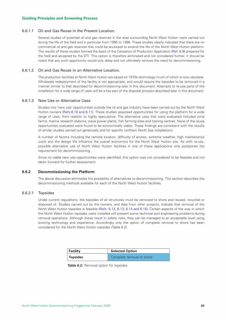
6.6.1.1 Oil and Gas Reuse in the Present Location.
Several studies of potential oil and gas reserves in the area surrounding North West Hutton were carried outduring the life of the field and in particular from 1995 to 1998. These studies clearly indicated that there are nocommercial oil and gas reserves that could be accessed to extend the life of the North West Hutton platform.The results of these studies formed the basis of the Cessation of Production Application (Ref. 6.9) prepared forthe field and accepted by the DTI. This option is therefore eliminated and not considered further. It should benoted that any such opportunity would only delay and not ultimately remove the need for decommissioning.
6.6.1.2 Oil and Gas Reuse in an Alternative Location.
The production facilities at North West Hutton are based on 1970s technology much of which is now obsolete.Wholesale redeployment of the facility is not appropriate, and would require the topsides to be removed in amanner similar to that described for decommissioning later in this document. Attempts to re-use parts of theinstallation for a wide range of uses will be a key part of the disposal process described later in this document.
6.6.1.3 New Use or Alternative Uses
Studies into ‘new use’ opportunities outside the oil and gas industry have been carried out by the North WestHutton owners (Refs.6.10 and 6.11). These studies assessed opportunities for using the platform for a widerange of uses, from realistic to highly speculative. The alternative uses that were evaluated included windfarms, marine research stations, wave power plants, fish farming sites and training centres. None of the reuseopportunities evaluated were found to be economically viable. These findings are consistent with the resultsof similar studies carried out generically and for specific northern North Sea installations.
A number of factors including the remote location, difficulty of access, extreme weather, high maintenancecosts and the design life influence the overall economics for the North West Hutton site. As with re-use,possible alternative use of North West Hutton facilities in one of these applications only postpones therequirement for decommissioning.
Since no viable new use opportunities were identified, this option was not considered to be feasible and nottaken forward for further assessment.
6.6.2 Decommissioning the Platform
The above discussion eliminates the possibility of alternatives to decommissioning. This section describes thedecommissioning methods available for each of the North West Hutton facilities.
6.6.2.1 Topsides
Under current regulations, the topsides of all structures must be removed to shore and reused, recycled ordisposed of. Studies carried out by the owners, and data from other projects, indicate that removal of theNorth West Hutton topsides is feasible (Refs. 6.12, 6.13, 6.14 and 6.15). Certain aspects of the way in whichthe North West Hutton topsides were installed will present some technical and engineering problems duringremoval operations. Although these result in safety risks, they can be managed to an acceptable level usingexisting technology and experience. Accordingly only the option of complete removal to shore has beenconsidered for the North West Hutton topsides (Table 6.2).
Guiding Principles and Screening Process
North West Hutton Decommissioning Programme February 2005 63
Facility Selected Option
Topsides Complete removal to shore
Table 6.2: Removal option for topsides.

6.6.2.2 Jacket
The base case for the decommissioning of the North West Hutton jacket is total removal. Studies on completejacket removal indicated that total removal of the jacket would present major technical and safety risks anduncertainties that required additional investigation (Refs. 6.13, 6.14, 6.15, 6.16 and 6.17). These issues arisewhen considering the removal of the whole jacket because of its size and complexity.
The greatest level of uncertainty is associated with the removal of the lower part of the jacket, from a depthof approximately 100m to the seabed at 140m. In this part of the jacket sometimes called the “footings”, thevery large legs and members in the final 25% of the height of the jacket account for about 50% of the totalweight. The potential engineering difficulties and safety risks attendant on removing such large and complexstructures is acknowledged in OSPAR Decision 98/3 (Ref. 6.3). This contains a provision to allow theconsideration by regulators of an application for “derogation” (exemption) from the requirement to completelyremove the footings of jackets weighing more than 10,000 tonnes.
In line with OSPAR Decision 98/3 alternative options for the jacket were therefore considered in detail using thecomparative assessment methodology. The short-list of possible options for the jacket is presented in Table 6.3.
6.6.4 Drill Cuttings
A comprehensive JIP recently completed by the United Kingdom Offshore Operators Association (UKOOA)(Ref.6.18), assessed the existing and potential long-term impacts of drill cuttings accumulations on theseabed. As a result of this study, the following management options were proposed for dealing with historicdrill cuttings piles: covering, removal and natural degradation in-situ. The studies concluded that there was nosingle, obvious course of action that would clearly provide the most appropriate solution in terms ofenvironmental benefit. The short-list of possible options for the North West Hutton drill cuttings pile ispresented in Table 6.4. This includes the additional option of “excavation” because this activity could be usedto expose the base of the jacket for total removal (see Section 9.6).
Guiding Principles and Screening Process
North West Hutton Decommissioning Programme February 200564
JacketFacility Options Selected for Assessment
Complete removal of thejacket. Jacket, footingsand template taken toshore for re-use orrecycling.
Removal of the jacketand partial removal of thefootings as close aspossible to the presentseabed level, i.e. the topof the drill cuttings.
Removal of the jacketdown to the top of thefootings at a depth ofapproximately 100m.
Table 6.3: Selected options assessed for jacket removal.
Figure 6.1: Jacket removal options.
Drill cuttingsIn-situ options Drill cuttings
Facility Options Selected for Assessment
Naturaldegradationin-situ
Excavate pileand leave atpresentlocation.
Cover pile withinert material.
Completeremoval tosurface and re-injectionoffshore.
Completeremoval toshore fordisposal.
Table 6.4: Selected options assessed for dealing with the drill cuttings pile.

6.6.5 Pipelines
Options for decommissioning the North West Hutton pipelines have been assessed in line with the DTIguidelines (Ref. 6.4) and the requirements of the Petroleum Act (1998) (Ref. 6.1).
All flexible lines and other ancillary pipeline equipment which are not trenched or buried will be completelyremoved to shore for recycling and disposal. The options for the two main pipelines are presented in Table 6.5.
Guiding Principles and Screening Process
North West Hutton Decommissioning Programme February 2005 65
10” gas import pipeline– PL 147
20” oil export pipeline– PL 148
Facility Options Selected for AssessmentComplete removal toshore.
Complete removal toshore.
Leave in-situ trenchedand buried.
Trench and bury. Leave in-situ on seabed.
Table 6.5: Selected options assessed for decommissioning pipelines PL 147 and PL 148
References
6.1 Petroleum Act 1998
6.2 1992 OSPAR Convention, Convention for the Protection of the Marine Environment of the North-EastAtlantic, 22nd September 1992.
6.3 1998 Ministerial Meeting of the OSPAR Commission, Sintra, Portugal on 22 – 23 July 1998, OSPARDecision 98/3, Date of Adoption 1998, Sintra.
6.4 DTI Oil and Gas Guidance Notes for Industry Decommissioning of Offshore Installations and Pipelinesunder the Petroleum Act 1998, Published by Offshore Decommissioning Unit, Department of Trade andIndustry, 21 August 2000.
6.5 Report of the Independent Review Group (IRG), Revision Final, 26th April 2004.
6.6 Joint Industries Project, Single Lift Concepts Summing Up, DNV Report No. 2001 – 0553, Rev 02.
6.7 Statutory Instrument 1992 No. 2885, The Offshore Installations (Safety Case) Regulations 1992.
6.8 HSE SPC/Enf/38 Guidance on ALARP for Offshore Division Inspectors, www.hse.gov.uk.
6.9 BP North West Hutton Field, Cessation of Production Application, Final Version 4.0, July 1999.
6.10 OWLET Group, North West Hutton Decommissioning Alternatives Study Report, Rev 1, 17th June 2002.
6.11 Twachtman Snyder & Byrd, Inc, Alternative Uses for East of Shetland Basin Facilities, Rev 1, August 2002.
6.12 Sasp Offshore Engineering UK, North West Hutton Decommissioning Study, Document No. 540039-02-LE-70002, Rev B, 9th March 1999.
6.13 Saipem, North West Hutton, Decommissioning Study, Supplementary Study Report, Document No.979924-REP-1001, Rev 01, 15th November 1999.
6.14 HEEREMA Marine Contractors, North West Hutton, Platform Removal Feasibility Study, Document No.E/1018 (2205), Rev 2, 29th October 1999.
6.15 Seaway Heavy Lifting, Removal and Transportation Methodology for North West Hutton Topsides andJacket Upper Sections Study, Document No. SHL.47.450.GM-011, Rev C, 1st November 1999.
6.16 “Report TEC 04A”, Noble Denton, North West Hutton Platform – Independent Comparative Assessmentof Partial and Total Jacket Removal, Document No. A4113/NDE/MGB/1, Rev 1, 4th July 2003.
6.17 “Report TEC04B”, Global Maritime, North West Hutton, Jacket Removal Study for Complete or PartialRemoval, Document No. GM-22875-0703-14708, Rev 0, 2nd July 2003.
6.18 UKOOA Drill Cutting Initiative, Final Report, February 2002.
6.19 “Report ENV 01”, BMT Cordah Ltd, Environmental Statement in support of the De-commissioning ofthe North West Hutton Facilities, Report No. BPX067/ES/2003, June 2004.
6.20 North West Hutton Abandonment Safety Case, Document No. NWH-ASC-001/002/003, 25th March 2004.
Guiding Principles and Screening Process
North West Hutton Decommissioning Programme February 200566

7 TOPSIDES DECOMMISSIONING
7.1 Introduction
There is a legal requirement that the topsides of all installations will be returned to shore for re-use or recycling.Detailed studies of structural integrity confirm that the topside components are capable of withstanding theoperations required to remove them to shore for recycling. It is therefore not necessary to consider alternativedecommissioning options. The potential for re-use and alternative use in the current location have beenthoroughly investigated and eliminated from further consideration as described in Section 6.
This section describes the potential methods for decommissioning the platform topsides by removing themand taking them to shore for recycling. It summarises the activities required to dispose of the modulesthemselves and the residual materials in the topsides systems.
The North West Hutton topsides comprise individual modules and components detailed in Sections 4 and 5which were installed on the module support frame by a SSCV in 1982. A total of 22 “heavy” lifts was requiredand the total weight of the topsides, with all of its tanks and pipes empty (the “dry weight”), is approximately20,160 tonnes.
Topsides Decommissioning
North West Hutton Decommissioning Programme February 2005 67
Photographs showing North West Hutton Topsides.
Pho
togr
aph
cour
tesy
of
Cha
rles
Hod
ge, L
owes
toft
, Nor
folk
This section:
• lists the potential removal methods;
• presents a summary description of each method;and
• describes the selection process and the proposedmethod for removal.

7.2 Description of Possible Removal Methods
There are several possible methods for removing the topsides. These are listed in Table 7.1 and described inmore detail in the Sections that follow.
7.2.1 Offshore Deconstruction
For removal by offshore deconstruction (sometimes referred to as “Piece-small” or “Piecemeal” removal) thetopsides would be broken up offshore using traditional cutting and lifting methods, and then transported toland in ordinary supply or cargo vessels. Personnel would methodically work their way through the topsides,using hydraulically-operated shears and other cutting equipment to dismantle the structure into piecesweighing no more than the rated lifting capacity of the platform cranes which is 55 tonnes. In general thepieces would weigh much less than this, e.g. pipe-work cut into lengths and put in skips. The major activitiesin this option would be:
• Empty and clean all pipes and vessels; this activity has been completed.
• Select and mark each piece of equipment and each section of module to be cut.
• Rig temporary scaffolding and lifting points as required.
• Take the weight of each piece on a crane, and use the shears to cut it free.
• Lift each piece out of the module, and deposit it on the platform or in a skip.
• Lift full skips / large items from the platform to a supply boat.
• Take full skips to shore for onward transportation and recycling.
The Piece-small option (Refs. 7.1 and 7.2) would use what is essentially onshore technology to perform a longprogramme of progressive dismantling that would have to be planned carefully to ensure the safety ofpersonnel. It is likely that several teams would work on the platform at once, and their work would have to beorganised to make best use of the limited space in the crowded topsides of North West Hutton.
Topsides Decommissioning
North West Hutton Decommissioning Programme February 200568
Table 7.1: Possible methods for removing the topsides.
Offshore deconstruction
Reverse installationwith HLV
Removal by “Single liftvessel”
Method DescriptionEach of the modules and components would be cut into small manageablepieces offshore, using hydraulic shears and other cutting techniques. Thesepieces would be removed using the platform cranes and then transported toshore on supply boats or transport barges.
The modules and other components that comprise the topsides would beseparated from each other and lifted from the platform using a HLV. Thisprogramme would effectively be a reverse of the original installation procedure.
The complete topsides would be removed in one piece by transferring it onto asingle lift decommissioning vessel.

7.2.2 Reverse Installation
It would be feasible to remove the modules using an SSCV, in a programme that was essentially the reverseof the installation process (Figure 7.1). Studies show that a series of 22 heavy lifts (Refs. 7.2, 7.3, 7.4, 7.5 and7.6) would be required to clear the topsides down to the module support frame. The major activities for thistechnique would be:
• Empty and clean all pipes and vessels; this activity has been completed.
• Disconnect the piping, electrical wiring and other services that link the modules;this activity has been completed.
• Remove or secure items of loose equipment.
• Install or reinstate lifting points on the modules.
• Separate the structural connections between the modules.
• Lift the modules onto the SSCV or transport barge and, if necessary, fasten in place.
• Transport all modules to shore for dismantling.
The individual structural integrity of the modules has not changed since installation, but offshore survey workwould be required to ensure that each section is sufficiently strong and stable enough to be lifted. In somecases it might be necessary to add additional strengthening or reinforcement prior to removal, but this shouldnot be significant. The majority of the lifting points were removed after installation to allow the modules to bestacked on each other. New lifting points would have to be installed and thoroughly tested prior to any liftingoperations.
Topsides Decommissioning
North West Hutton Decommissioning Programme February 2005 69
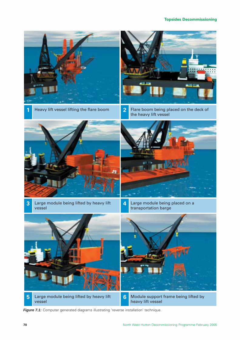
Topsides Decommissioning
North West Hutton Decommissioning Programme February 200570
Heavy lift vessel lifting the flare boom Flare boom being placed on the deck of the heavy lift vessel
Large module being lifted by heavy lift vessel
Large module being placed on a transportation barge
Large module being lifted by heavy lift vessel
Module support frame being lifted by heavy lift vessel
1 2
3 4
5 6
Figure 7.1: Computer generated diagrams illustrating ‘reverse installation’ technique.

7.2.3 Single Lift
The term “single lift” applies to those options in which a vessel is used to lift off the topsides with only aminimum requirement for offshore deconstruction. Several designs have been proposed for purpose-builtsingle lift decommissioning vessels that would be capable of removing topsides or steel jackets in one pieceand transporting them to shore (Figures 7.2a, 7.2b and 7.2c). The designs include modified oil tankers or semi-submersibles, innovative new semi-submersibles, and arrangements of barges. These methods remainunproven, however, and no such vessel is currently available for a platform the size of North West Hutton(Refs. 7.8 and 7.9).
The major activities in this option would be:
• Strengthen the MSF for single lift activity by installing additional structural steel.
• Pre-cut the MSF to separate it from the jacket legs.
• Manoeuvre the single lift vessel alongside and around the jacket.
• Make load bearing connections between the topsides and the single lift vessel.
• Transfer the load from the jacket legs to the vessel and lift the topsides from the jacket.
• Transport to shore and transfer the whole topsides to land / near-shore location.
Note The three ‘single lift’ methods illustrated above are not currently available.
7.3 Selection of Removal Method
7.3.1 Introduction
The potential removal methods for decommissioning the topsides were assessed using the methodologydescribed in Section 6. This included consideration of the following issues:
• the technical difficulty, including the timely availability of fit-for-purpose equipment, procedures andpeople, such that the option can be completed successfully;
• the potential safety risk to our personnel, contractors and other third parties;
• the potential to cause environmental impact at sea, on land, or in the atmosphere;
• the impact on society in general; and
• the cost, including the need for pre-investment, the reliability of cost estimates and the potential forcost over-run.
The issues that differentiate the removal methods most clearly are technical complexity and safety, and theassessment focussed on these issues. The technical complexity, particularly for single-lift methods, alsoresulted in cost uncertainty.
Several reports and studies were commissioned (Refs. 7.8 and 7.9) to examine the relative merits of eachmethod in the various criteria. Some of the reports presented qualitative information based on industryexperience, interviews with engineering companies and contractors, or an analysis of historical performance.
Topsides Decommissioning
North West Hutton Decommissioning Programme February 2005 71
Figure 7.2c: Excalibur ‘single lift’method (Ref. 7.15).
Figure 7.2b: Monitor ‘singlelift’ method (Ref. 7.16).
Figure 7.2a: MPU Heavy Lifter‘single lift’ method (Ref.7.17).
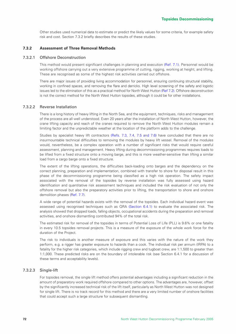
Other studies used numerical data to estimate or predict the likely values for some criteria, for example safetyrisk and cost. Section 7.3.2 briefly describes the results of these studies.
7.3.2 Assessment of Three Removal Methods
7.3.2.1 Offshore Deconstruction
This method would present significant challenges in planning and execution (Ref. 7.1). Personnel would beworking offshore carrying out a very extensive programme of cutting, rigging, working at height, and lifting.These are recognised as some of the highest risk activities carried out offshore.
There are major issues of providing living accommodation for personnel, ensuring continuing structural stability,working in confined spaces, and removing the flare and derricks. High level screening of the safety and logisticissues led to the elimination of this as a practical method for North West Hutton (Ref 7.2). Offshore deconstructionis not the correct method for the North West Hutton topsides, although it could be for other installations.
7.3.2.2 Reverse Installation
There is a long history of heavy lifting in the North Sea, and the equipment, techniques, risks and managementof the process are all well understood. Even 20 years after the installation of North West Hutton, however, thecrane lifting capacity and reach of the cranes required to remove the North West Hutton modules remain alimiting factor and the unpredictable weather at the location of the platform adds to the challenge.
Studies by specialist heavy lift contractors (Refs. 7.3, 7.4, 7.5 and 7.6) have concluded that there are noinsurmountable technical difficulties to removing the modules by heavy lift vessel. Removal of the moduleswould, nevertheless, be a complex operation with a number of significant risks that would require carefulassessment, planning and management. Heavy lifting during decommissioning programmes requires loads tobe lifted from a fixed structure onto a moving barge, and this is more weather-sensitive than lifting a similarload from a cargo barge onto a fixed structure.
The extent of the lifting operations, the difficulties back-loading onto barges and the dependency on thecorrect planning, preparation and implementation, combined with transfer to shore for disposal result in thisphase of the decommissioning programme being classified as a high risk operation. The safety impactassociated with the removal of the topsides by reverse installation was fully assessed using hazardidentification and quantitative risk assessment techniques and included the risk evaluation of not only theoffshore removal but also the preparatory activities prior to lifting, the transportation to shore and onshoredemolition phases (Ref. 7.7).
A wide range of potential hazards exists with the removal of the topsides. Each individual hazard event wasassessed using recognised techniques such as QRA (Section 6.4.1) to evaluate the associated risk. Theanalysis showed that dropped loads, falling objects, occupational accidents during the preparation and removalactivities, and onshore dismantling contributed 94% of the total risk.
The estimated risk for removal of the topsides in terms of Potential Loss of Life (PLL) is 9.6% or one fatalityin every 10.5 topsides removal projects. This is a measure of the exposure of the whole work force for theduration of the Project.
The risk to individuals is another measure of exposure and this varies with the nature of the work theyperform, e.g. a rigger has greater exposure to hazards than a cook. The individual risk per annum (IRPA) to afatality for the higher risk categories, which include rigging crew and tugboat crew, are 1:1,500 to greater than1:1,000. These predicted risks are on the boundary of intolerable risk (see Section 6.4.1 for a discussion ofthese terms and acceptability levels).
7.3.2.3 Single-lift
For topsides removal, the single lift method offers potential advantages including a significant reduction in theamount of preparatory work required offshore compared to other options. The advantages are, however, offsetby the significantly increased technical risk of the lift itself, particularly as North West Hutton was not designedfor single lift. There is no track record for this method and there are a very limited number of onshore facilitiesthat could accept such a large structure for subsequent dismantling.
Topsides Decommissioning
North West Hutton Decommissioning Programme February 200572
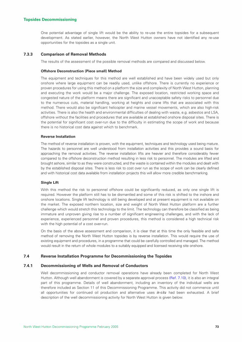
One potential advantage of single lift would be the ability to re-use the entire topsides for a subsequentdevelopment. As stated earlier, however, the North West Hutton owners have not identified any re-useopportunities for the topsides as a single unit.
7.3.3 Comparison of Removal Methods
The results of the assessment of the possible removal methods are compared and discussed below.
Offshore Deconstruction (Piece small) Method
The equipment and techniques for this method are well established and have been widely used but onlyonshore where large equipment can be readily used, unlike offshore. There is currently no experience orproven procedures for using this method on a platform the size and complexity of North West Hutton, planningand executing the work would be a major challenge. The exposed location, restricted working space andcongested nature of the platform means there are significant and unacceptable safety risks to personnel dueto the numerous cuts, material handling, working at heights and crane lifts that are associated with thismethod. There would also be significant helicopter and marine vessel movements, which are also high-riskactivities. There is also the health and environmental difficulties of dealing with waste, e.g. asbestos and LSA,offshore without the facilities and procedures that are available at established onshore disposal sites. There isthe potential for significant cost over-run due to the difficulty in estimating the scope of work and becausethere is no historical cost data against which to benchmark.
Reverse Installation
The method of reverse installation is proven, with the equipment, techniques and technology used being mature.The hazards to personnel are well understood from installation activities and this provides a sound basis forapproaching the removal activities. The reverse installation lifts are heavier and therefore considerably fewercompared to the offshore deconstruction method resulting in less risk to personnel. The modules are lifted andbrought ashore, similar to as they were constructed, and the waste is contained within the modules and dealt withby the established disposal sites. There is less risk to cost over run as the scope of work can be clearly definedand with historical cost data available from installation projects this will allow more credible benchmarking.
Single Lift
With this method the risk to personnel offshore could be significantly reduced, as only one single lift isrequired. However the platform still has to be dismantled and some of this risk is shifted to the inshore andonshore locations. Single lift technology is still being developed and at present equipment is not available onthe market. The exposed northern location, size and weight of North West Hutton platform are a furtherchallenge which would stretch this technology to the limit. The technology can therefore be classified as beingimmature and unproven giving rise to a number of significant engineering challenges, and with the lack ofexperience, experienced personnel and proven procedures, this method is considered a high technical riskwith the high potential of a cost over-run.
On the basis of the above assessment and comparison, it is clear that at this time the only feasible and safemethod of removing the North West Hutton topsides is by reverse installation. This would require the use ofexisting equipment and procedures, in a programme that could be carefully controlled and managed. The methodwould result in the return of whole modules to a suitably equipped and licensed receiving site onshore.
7.4 Reverse Installation Programme for Decommissioning the Topsides
7.4.1 Decommissioning of Wells and Removal of Conductors
Well decommissioning and conductor removal operations have already been completed for North WestHutton. Although well abandonment is covered by a separate approval process (Ref. 7.10), it is also an integralpart of this programme. Details of well abandonment, including an inventory of the individual wells aretherefore included as Section 11 of this Decommissioning Programme. This activity did not commence untilall opportunities for continued oil production and alternative uses in-situ had been exhausted. A briefdescription of the well decommissioning activity for North West Hutton is given below.
Topsides Decommissioning
North West Hutton Decommissioning Programme February 2005 73
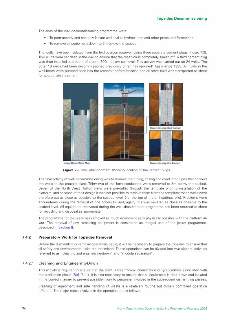
The aims of the well decommissioning programme were:
• To permanently and securely isolate and seal all hydrocarbon and other pressured formations.
• To remove all equipment down to 3m below the seabed.
The wells have been isolated from the hydrocarbon reservoir using three separate cement plugs (Figure 7.3).Two plugs were set deep in the well to ensure that the reservoir is completely sealed off. A third cement plugwas then installed at a depth of around 500m below sea level. This activity was carried out on 24 wells. Theother 16 wells had been decommissioned previously on an “as required” basis since 1993. All fluids in thewell bores were pumped back into the reservoir before isolation and all other fluid was transported to shorefor appropriate treatment.
The final activity of well decommissioning was to remove the tubing, casing and conductor pipes that connectthe wells to the process plant. Thirty-two of the forty conductors were removed to 3m below the seabed.Seven of the North West Hutton wells were pre-drilled through the template prior to installation of theplatform, and because of their design it was not possible to retrieve them from the template; these wells weretherefore cut as close as possible to the seabed level, (i.e. the top of the drill cuttings pile). Problems wereencountered during the retrieval of one conductor and, again, this was severed as close as possible to theseabed level. All equipment recovered during the well abandonment programme has been returned to shorefor recycling and disposal as appropriate.
The programme for the wells has removed as much equipment as is physically possible with the platform in-situ. The removal of any remaining equipment is considered an integral part of the jacket programme,described in Section 8.
7.4.2 Preparatory Work for Topsides Removal
Before the dismantling or removal operations begin, it will be necessary to prepare the topsides to ensure thatall safety and environmental risks are minimised. These operations can be divided into two distinct activitiesreferred to as “cleaning and engineering-down” and “module separation”.
7.4.2.1 Cleaning and Engineering-Down
This activity is required to ensure that the plant is free from all chemicals and hydrocarbons associated withthe production phase (Ref. 7.11). It is also necessary to ensure that all equipment is shut down and isolatedin the correct manner to prevent possible injury to personnel involved in the subsequent dismantling phases.
Cleaning of equipment and safe handling of waste is a relatively routine but closely controlled operationoffshore. The major steps involved in the operation are as follows:
Topsides Decommissioning
North West Hutton Decommissioning Programme February 200574
Figure 7.3: Well abandonment showing location of the cement plugs.

• Remove all hydrocarbons from the production systems by purging and flushing to the normal handlingand export systems.
• Systematically isolate equipment from all power and production inputs and outputs and ensure that itis safe for human intervention or access.
• Open systems and remove any remaining production residues, chemicals and other materials. Ensurethese are stored correctly and disposed of via the appropriate disposal route.
• Once these activities have been completed, each system is “signed off” by the technical authority ascleaned and non-hazardous.
This work has been completed for the North West Hutton Platform. An independent residual waste survey (Ref.7.12) has been conducted to estimate the waste remaining post-cleaning, and to enable an inventory of thetopsides to be provided to the onshore dismantling yard. The results of this survey were summarised in Section 5.
7.4.2.2 Module Separation
The second stage of preparation for removal (Ref. 7.13) involves:
• Cutting and separating the process piping, electrical connections and other services that connect theplatform systems between each module. This work was completed in July 2004.
• Structural separation of the modules so that they can be lifted individually from the topsides. Thisinvolves removing the welds and structural connections that hold each of the components together.There is also a substantial amount of work involved in removing walkway sections and other items thatinterlink the various modules. The major part of this work will take place immediately before theremoval of the topsides.
7.4.3 Lifting and Transportation to Shore
After completion of the preparation activities, the crane vessel will remove the modules sequentially andposition them either on the crane vessel itself or on to a prepared barge. The modules will be sea-fastenedinto position and transported to the designated onshore dismantling yard (Refs. 7.3, 7.4, 7.5 and 7.6). Thelifting, sea-fastening and onwards transportation of the topsides will consist of complex operations requiringcareful planning and engineering assessment to minimise the high potential risk.
7.4.4 Receiving and Dismantling Onshore
The onshore receiving location for dismantling North West Hutton has not yet been selected and it is possiblethat more than one site will be used. The Environmental Impact Assessment (Ref.7.14) has therefore notevaluated the onshore environmental impacts of using a specific disposal site for the North West Huttontopsides. It has, however, assessed generic onshore environmental impacts, for example those arising fromthe transportation of material by road, onshore dismantling, and recycling and reprocessing, at two establishedlocations. The assessment of potential impacts at these sites does not preclude the use of alternative sites,and it should be noted that the final site(s) will only be selected after rigorous assessment and confirmationthat all the necessary permits, procedures, competences and other requirements are in place.
Because of the size of the modules, it is likely that they will be stored at or close to the receiving quay priorto dismantling. The modules will be transferred onshore and then held in a secure area equipped to contain,handle and treat any potential liquid contaminants and rainwater run-off.
It is unlikely that any of the North West Hutton modules will be suitable for re-use (Section 6.6.1). New usesmay be found for certain individual items, particularly turbines, pumps and motors. For all other componentsthe North West Hutton owners plan to maximise the amount of material that is recycled, and aim to re-cycle97% of the topsides material by weight (Ref. 7.14).
Recommendation: The topsides should be totally removed by the reverse installationmethod and returned to shore for reuse, recycling or disposal.
Topsides Decommissioning
North West Hutton Decommissioning Programme February 2005 75
References
7.1 Eric Faulds Associates Ltd; North West Hutton Topsides Piece Small Dismantling Study. April 2003.
7.2 BP; North West Hutton Decommissioning Select Phase Recommendation – Method of Removal forTopsides and Jacket, Rev 1, April 2003.
7.3 Sasp Offshore Engineering UK, North West Hutton Decommissioning Study, Document No. 540039-02-LE-70002, Rev B, 9th March 1999.
7.4 Saipem, North West Hutton, Decommissioning Study, Supplementary Study Report, Document No.979924-REP-1001, Rev 01, 15th November 1999.
7.5 HEEREMA Marine Contractors, North West Hutton, Platform Removal Feasibility Study, Document No.E/1018 (2205), Rev 2, 29th October 1999.
7.6 Seaway Heavy Lifting, Removal and Transportation Methodology for North West Hutton Topsides andJacket Upper Sections Study, Document No. SHL.47.450.GM-011, Rev C, 1st November 1999.
7.7 Quantitative Risk Assessment of the Removal of the North West Hutton Topsides (BP Ref. SAF2E)Risk Support, 19th March 2004.
7.8 Joint Industries Project, Single Lift Concepts Summing Up, DNV Report No. 2001 – 0553, Rev 02.
7.9 “Study FT04” Noble Denton, North West Hutton, Comparative Assessment of Marine Options forPlatform Removal, Document No. EOS-NWHD-NOB-FAC-REP-001, Rev A, 19th November 1999.
7.10 Department of Trade and Industry (DTI) Well Operations and Notifications System (WONS) WellAbandonment Consents.
7.11 Wood Group / Rigblast, North West Hutton Decommissioning Project, Front End Engineering Design(Engineering Down and Cleaning), Document No. 37NWH-E0340047-Z-RE-0001-000, October 2002.
7.12 Lloyd’s Register, North West Hutton Decommissioning Residual Waste Survey, Reference0391215/R/003, February 2004.
7.13 Wood Group / Rigblast, North West Hutton Decommissioning Project, Module Process & UtilitySeparation FEED, Document No. 37NWH-E034F0047-Z-RE-0006, October 2003.
7.14 “Report ENV01”, Environmental Statement in support of the De-commissioning of the North WestHutton Facilities, Report No. BPX067/ES/2003, June 2004.
7.15 Excalibur Engineering BV website: www.excalibur-engineering.com.
7.16 Monitor, website: www.monitoroil.com.
7.17 MPU Enterprise AS, website: www.mpu.no.
General References
Wood Group Engineering (WGE), North West Hutton, Class III Scope Definition for Preparation ofTopsides for Removal, WGE Doc No. 37E034F0003/SE/RE/001, October 1999.
Wood Group Engineering Ltd, North West Hutton Platform De-commissioning Study, Document No.37E034F0032/IE/SU/001, Rev B, dated 12/12/01.
Topsides Decommissioning
North West Hutton Decommissioning Programme February 200576

8 JACKET DECOMMISSIONING
8.1 Introduction and Background
The screening studies on removal technologies and options (Section 6) have shown that it is not feasible touse the jacket for any other purpose at its present location. As a result of this finding, a series of studies wascommissioned to evaluate removal of the jacket structure.
This section presents a comprehensive summary of the study work undertaken and the subsequent findings.The following topics are covered:
• a description of the condition of the jacket;
• an assessment of possible methods for removing the whole jacket down to the seabed;
• an evaluation of the technical, safety, environmental, societal and cost implications of undertakingjacket removal;
• a comparative evaluation of alternative removal options involving the partial removal of the jacket; and
• a recommended option for decommissioning the jacket.
It should be noted that this evaluation assesses the removal of the jacket as a stand-alone operation. Thepresence of the drill cuttings around and covering the base of the jacket structure is not included as part ofthe evaluation at this stage. The rationale for this is to ensure that the full implications of jacket removal areunderstood without other factors complicating or masking issues.
8.2 Present Condition of the Jacket
The North West Hutton jacket is the largest fixed steel, offshore oil and gas structure that has been consideredfor decommissioning anywhere in the world to date. Information about its structure, composition anddimensions is presented in Sections 4 and 5 of this programme. A detailed understanding of the condition ofthe structure is an essential starting point for effective evaluation of removal options.
During its working life, the platform was regularly inspected and independently certified for continuedoperation. This inspection regime will continue until the platform is removed.
During installation of the jacket in 1981, the piling operation to secure it to the seabed was interrupted bya severe storm. Movement of the partially secured structure during this storm resulted in significantdamage to the lower parts of the jacket. Following the storm, the piling process to secure the jacket wascompleted successfully, but a major programme of inspection and repair was necessary to ensure the long-term integrity of the structure. The damage that was sustained, and the subsequent remedial work, is fullydocumented (Refs. 8.1, 8.2 and 8.3), and the issues which have a particular bearing on decommissioningare as follows:
• Large sections of plan bracing elements at the seabed level, necessary for the integrity of the jacketduring transport and launching, became detached or were intentionally severed. Numerous crackedwelds were detected and repairs implemented where necessary to restore structural integrity.
• A large accumulation of grout (cement) was detected around Leg B1 and there is grout around theother three main legs (Figures 8.2a and 8.2b). The jacket was designed to allow the piles to be driveninto the seabed to form the piled foundation and then the piles connected to the jacket by means ofgrout, thereby supporting the platform weight on the piles. This grouted connection was made by fillingthe annuli between the pile and pile sleeve with grout (see figure 8.1), where the bottom of the annuliwas sealed by pre-installed rubber packers. A large number of these packers failed due to stormdamage and the grout leaked out. In some cases, i.e. leg B1, several attempts were necessary beforethe bottom of the annuli were sealed and a large quantity of grout leaked out onto the lower sectionsof steelwork, i.e. the mud mats, and the seabed.
• Four major structural clamps were mechanically attached to the jacket at a depth of 130m and groutedin place to restore structural integrity and original design life.
Jacket Decommissioning
North West Hutton Decommissioning Programme February 2005 77

Jacket Decommissioning
North West Hutton Decommissioning Programme February 200578
Pile sleeves
Seabed
Piles
Bottle leg
Module SupportFrame
Piles
Corner leg
Pile guides
Footings
Figure 8.1: Computer generated diagram of the North West Hutton jacket.

8.3 Assessment of Jacket Removal Options
8.3.1 Introduction
OSPAR Decision 98/3 (Ref. 8.5) includes a presumption of complete removal for all offshore structures. Therange of studies undertaken for the North West Hutton jacket complies with this requirement and includesscreening studies to evaluate techniques, and a range of detailed studies to fully understand the implicationsof undertaking those techniques.
The overall purpose of the study work was to:
• identify all of the currently available techniques, and the potential new techniques, for jacket removal;
• assess the technical, safety, environmental, societal and cost implications of removing the North WestHutton jacket; and
• provide information to identify one or more techniques that could be safely and effectively used toremove the North West Hutton jacket.
The studies were carried out by a range of companies, including structural experts, safety specialists, removalcontractors, diving contractors and specialist demolition companies.
Jacket Decommissioning
North West Hutton Decommissioning Programme February 2005 79
New members / joint reinforcement
Key:
New Members
Joint Reinforcement
Bottle Leg
The mud mat and lower section of pile sleeves for leg B1 are covered in hardened grout to a depth of approximately 1 metre. Grout also exists at the three other legs but not to the same extent.
Figure 8.2a: Computer generated diagram indicating therepaired sections of the lower part of the jacket and thegrout around Leg B1.
Separated Members
Separated MemberSeparated Member Attached Member
Separated Members To Leg B1 only.
Attached Member
Separated Frame
B1
A1
A2A3
B2B3
A4
B4
Unknown Grout Coverage
Figure 8.2b: Engineering diagram showing the repairedsections to the lower part of the jacket (Ref. 8.3).

8.3.2 Summary and Screening of Removal Techniques
All the potential methods for removing the jacket can be grouped into the following three categories (Ref. 8.6):
• Reverse installation.
• Single lift.
• Offshore deconstruction.
The screening process reviewed the application of these techniques for North West Hutton, and issummarised below.
8.3.2.1 Reverse Installation
Reverse installation is not a practical option. The North West Hutton jacket was constructed onshore, launchedfrom a transport barge at the field location and then floated into its final position. The closest approximationfor the reverse installation would be to attach a buoyancy system to the structure and then use it to “re-float”the entire jacket so that it could be towed to an inshore deconstruction site (Ref. 8.7). No such systems arecurrently available for applications of this magnitude and it is doubtful if the method is feasible for North WestHutton because of the damage to the jacket.
8.3.2.2 Single Lift
Single lift would entail using a purpose-built vessel, preferably capable of lifting the entire structure, to lift itfrom the seabed and either carry it to shore or positioning it on a barge for transport to the dismantling site.BP and a number of other companies (Ref. 8.8) recognised the potential importance of these techniques anda number of joint projects have been funded and carried out to develop the technology. At present, no singlelift systems of sufficient capacity for the North West Hutton jacket are available.
In order to fully assess reverse installation and single lift, it is necessary to consider the ability of the jacket tobe lifted by such a method. During the initial launch and also during any potential recovery by methods suchas those described above, the jacket would have to withstand considerable dynamic forces due to the loadingfrom raising of the entire structure, wave and current action, and the resultant motion of the vessels andsubsequent transportation.
A detailed study was carried out to determine if the North West Hutton jacket could withstand these forces(Ref. 8.9). The study used “finite element modelling”, a detailed computer-aided engineering tool, to assessthe condition of the structure at every stage of the operation. The study clearly showed a high probability thatthe jacket would collapse during such an operation. The main reason for the predicted collapse is the loss ofjacket strength resulting from the damage and subsequent removal of the plan bracing at the seabed level.The main function of this bracing was to provide support to the bottle legs during the original transportationand launch of the jacket. Re-instatement of this bracing is not feasible.
There are several different concepts for implementing such operations, but at present many do not have thesize or capacity to lift a jacket as large as North West Hutton, and transport it to the UK. They would also haveto deal with the damage and stability problems described above. Reverse installation and single lift weretherefore eliminated as options that were presently not viable for removing the complete jacket as a singleunit, and they were not subjected to additional analysis.
8.3.2.3 Offshore Deconstruction
Offshore deconstruction, using a crane vessel, has been used to remove jackets but it has never beenimplemented on a jacket of this size. Several small jackets have been successfully removed using cranevessels, for example in the Southern North Sea, but these effectively constitute reverse installation operationsas the jacket is lifted from the seabed as a complete unit.
Offshore deconstruction involves severing the steel members of the jacket in a sequential operation to detachsections of various sizes that are then removed by a large floating crane. The operation starts at the top of thejacket and systematically progresses down towards the seabed. The severed sections are then safelypositioned and secured on the crane vessel or barges for transport to shore. The maximum size of theindividual sections that can be removed is governed by the lift capacity of the crane vessel and the practicalconstraints of positioning and securing the sections for transportation.
Jacket Decommissioning
North West Hutton Decommissioning Programme February 200580
At present, therefore, offshore deconstruction using a heavy lift crane vessel is the only viable method forremoval and transportation of the complete North West Hutton jacket. The following sections describe howthis technique could be used to remove the North West Hutton jacket.
8.4 Assessment of Jacket Removal by Offshore Deconstruction
8.4.1 Introduction
The removal of the North West Hutton jacket by offshore deconstruction has been studied in detail over a numberof years. A wide range of technologies is required and a clear understanding of the complex equipmentrequirements and removal operations is necessary. The expertise to implement such operations resides with asmall number of highly specialised and competent contractors and sub-contractors. These contractors and otherspecialists were utilised to develop a thorough technical understanding of the removal operations.
8.4.2 Jacket Removal Overview
The main studies (Refs. 8.10, 8.11, 8.12, 8.13, 8.14 and 8.15) to determine the technical aspects of jacketremoval were carried out by marine and sub-sea contractors with expertise in the field. These contractorsoperate the crane vessels and sub-sea equipment that would be required to remove the jacket. There is notrack-record of removing a structure the size of the North West Hutton jacket by any technique, includingoffshore deconstruction. The studies examined in detail the deconstruction sequence necessary for completeremoval of the jacket and template down to the original seabed.
The reports made different recommendations on certain key aspects, including where to section the jacket,the cutting methodology and the total number of lifts required. The studies highlighted a number of commonrisks which represented the key offshore considerations for removal, and required additional assessmentbefore any detailed methodology could be developed for the implementation of a removal programme. Theseare as follows:
• The amount of preparatory work required before each lift, e.g. cleaning and removal of anodes.
• The reliability of cutting techniques and the need to confirm that each member has been successfullycut (Refs. 8.16, 8.17 and 8.18).
• The need to develop and apply large-scale rigging techniques so that large sections of the jacket could besecurely attached to a crane and lifted safely, with minimal risk of a dropped load (Refs. 8.16, 8.17 and 8.18).
• The safety risks associated with the likely requirement to deploy divers during a complexdeconstruction activity (Refs. 8.19, 8.20 and 8.21).
• The risks associated with placing and securing (“back-loading”) large sections on a barge safely, whileit is moving in the seaway.
• Specific difficulties related to the lower-most sections of the jacket and the template (Refs. 8.21,8.22 and 8.23), including the damage to the jacket, the presence of excessive grout, and inter-actionwith the drill cuttings.
Some of the risks, such as cutting effectiveness, remain unchanged regardless of the stage of operations orthe depth at which an activity is taking place. Others vary with the depth of the operation; for example, waveloading is a concern near the surface and structural uncertainty is a major concern at the base of the jacket.
The risks and uncertainties, such as the safety of personnel, use of divers, dropped loads and fallingobjects (Refs. 8.21 and 8.22) were of sufficient concern that a comparative assessment of the jacketremoval options was undertaken, this includes an additional study (Ref. 8.25) to compare the technicalchallenges of the removal options. The overall assessment methodology was discussed in Section 6and the results are described below.
8.5 Comparative Assessment of Jacket Removal Options
8.5.1 Introduction
Using the methodology described in Section 6, the comparative assessment for the jacket examined threedifferent scenarios for full and partial removal of the jacket, as outlined below (Figure 8.3).
Jacket Decommissioning
North West Hutton Decommissioning Programme February 2005 81
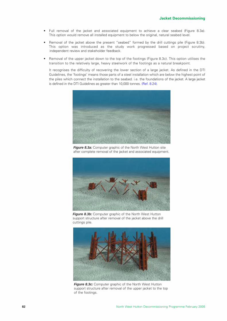
• Full removal of the jacket and associated equipment to achieve a clear seabed (Figure 8.3a).This option would remove all installed equipment to below the original, natural seabed level.
• Removal of the jacket above the present “seabed” formed by the drill cuttings pile (Figure 8.3b).This option was introduced as the study work progressed based on project scrutiny, independent review and stakeholder feedback.
• Removal of the upper jacket down to the top of the footings (Figure 8.3c). This option utilises thetransition to the relatively large, heavy steelwork of the footings as a natural breakpoint.
It recognises the difficulty of recovering the lower section of a large jacket. As defined in the DTIGuidelines, the ‘footings’ means those parts of a steel installation which are below the highest point ofthe piles which connect the installation to the seabed. i.e. the foundations of the jacket. A large jacketis defined in the DTI Guidelines as greater than 10,000 tonnes. (Ref. 8.24).
Jacket Decommissioning
North West Hutton Decommissioning Programme February 200582
Figure 8.3a: Computer graphic of the North West Hutton siteafter complete removal of the jacket and associated equipment.
Figure 8.3b: Computer graphic of the North West Huttonsupport structure after removal of the jacket above the drillcuttings pile.
Figure 8.3c: Computer graphic of the North West Huttonsupport structure after removal of the upper jacket to the topof the footings.

These three decommissioning options for the jacket were subject to a detailed study and review process,which provided specific information relating to each of the assessment criteria; Technical, Safety,Environmental, Societal and Economic. The remainder of this section describes the assessments and thefindings of the studies.
8.6 Assessment of the Option of Full Jacket Removal
The proven method for removing the jacket is to cut it into sections underwater, and lift the sections onto thecrane vessel or barges for transportation to land. This section presents a description of the technical andengineering programme of work that would be undertaken to implement this option.
8.6.1 Technical Description of Removal Operations
8.6.1.1 Description of Preparatory Work Offshore
Removal of the jacket would require the use of heavy plant, barges and support systems similar to those thatwould be used for the removal of the topsides. The operations would be a greater challenge, because removalof the jacket would require co-ordination of sub-sea and surface activities. The following description assumesthat the topsides and module support frame have been successfully removed prior to commencing the jacketremoval operations offshore.
The entire programme would need to be planned in great detail. The position of each cut, and the size and weightof each individual section would be determined together with an assessment of how the component wouldbehave when submerged and how the behaviour changes as large volumes of water drain out as it is brought tothe surface. Contingency measures would also have to be planned; for example, divers may be required to setup the cutting equipment in difficult situations, for rigging deployment, or in the event of a tool failure.
Large steel supports and structures for securing each section for transport would be designed and fabricatedprior to the operation. The barges would be prepared for receiving and carrying each specific load.
Inspection of the jacket would be required prior to any operations and before each section was removed.
8.6.1.2 Description of Cutting and Lifting Operations
Some preparation of the structure would be carried out by support vessels in advance of the main liftingoperation. The main operation would, however, require co-ordination of the crane vessel, transport barges andsupport vessels (Figure 8.4).
Each component would have to be properly secured while it was being cut, because of the large residual stressesthat exist in a structure of this size. No such method is available for a structure as large as North West Huttonand a new system would have to be designed and tested. The final cuts to free each section would be crucial asthe crane would be attached at this time. Any delay caused by malfunction or failure of the cutting operation atthis stage could result in structural failure, damage to equipment or other major operational problems.
Existing cutting techniques have not been used on a jacket the size of North West Hutton, which has largediameter legs containing internal components (Refs. 8.16, 8.17 and 8.18). One of the major tasks in thisprogramme would therefore be to extend the range and capability of the equipment so that it could safely andefficiently cut and lift the large sections of the North West Hutton jacket.
It would be preferable, from a safety point of view, to deploy remotely operated subsea work vehicles (ROVs)to carry out all the work, without the requirement for divers. The offshore industry has made significantadvances in the design and application of remote operations, but the studies indicate it is probable that diverswould be required for some of the removal operations (Refs. 8.21 and 8.23). The most likely requirement fordivers would be during the removal of the lower-most parts of the jacket. Cleaning and cutting operations herewould be complex, where the jacket and the template are surrounded by grout and other material thatprevents them from being freed from the seabed using remotely operated cutting techniques. Theseoperations would pose a high safety risk to divers.
Jacket Decommissioning
North West Hutton Decommissioning Programme February 2005 83

Jacket Decommissioning
North West Hutton Decommissioning Programme February 200584
Due to the sheer size of the jacket, it requiresto be cut into 15 to 20 sections. Over 100 jacket members will have to be cut, some with a diameter as large as 3 metres. This shows cutting using diamond wire techniques
Top section of the jacket being lifted by a heavy lift vessel to be placed onto a transportation barge
Small subsea section of the jacket beinglifted to the surface by heavy lift vessel
Jacket section being lowered onto a barge for transportation to the shore for disposal
Large subsea section of the jacket beinglifted to the surface by heavy lift vessel
Jacket footings on the seabed
1 2
3 4
5 6
Figure 8.4: Computer generated diagrams showing examples of the type of lifts required to get to top of footings.

Jacket Decommissioning
North West Hutton Decommissioning Programme February 2005 85
8.6.1.3 Description of Operations to Transfer Loads and Transport them to Land for Dismantling
Whilst not routine, the use of cranes, vessels and barges to transfer loads, is a relatively well-known, andclosely controlled and monitored, activity for offshore operations. Knowledge of such operations is derivedmainly from construction activities, including the lifting and placement of jackets, topsides and modules.Unlike installation operations, however, the exact weight, condition and geometry of the lifts required fordismantling will not be known in advance. In addition, transferring a large load onto a barge in open seas is adifficult and high-risk marine operation (Figure 8.4).
These uncertainties would require additional focus on planning and preparation, in addition to more closelycontrolled procedures for implementing the operations. Once the removed section arrived at the surface itwould be inspected, before being set down on a specially-constructed support frame known as “grillage”.This is a welded framework of beams and plates several metres high, located on the deck of thetransportation barge, that supports the weight of the jacket section and resists the dynamic loadsencountered in transportation.
Sea fastening, consisting of plates and tubes welded in place, would be used to hold each section of jacketon the grillage. The sea fastening operation is a particularly hazardous part of the overall procedure becausethe deck personnel would potentially be exposed to falling objects, and the movement of an unstable load.Sections would be transported either on the deck of the crane vessel or on a separate transport barge.
During all of these procedures, including onshore demolition there would be a significant safety risk to peopleand plant due to falling objects including loose structural components, marine growth and, particularly, groutand drill cuttings from the lower sections (Refs. 8.22, 8.26, 8.27, 8.28. 8.29 and 8.30).
8.6.1.4 Description of Onshore Dismantling Operations
At the onshore receiving sites, components would be further dismantled using remote and manualcutting techniques. Hydraulic shears would be used to cut through steel bracings and smallercomponents. Larger components, including the relatively thick steel in the footings, would be dismantledusing hot or cold cutting techniques.
Standard rigging and lifting equipment, and ancillary equipment, would be used to lift, move and hold many ofthe items during these processes.
The aim of onshore dismantling would be to break down material into pieces approximately 1.5m x 0.5m. Thisis the recommended size for delivery to steel recycling plants.
All the anodes on the structure would be removed at the onshore receiving site and would be transported to asuitable facility for recycling. The steel would be sent for recycling although, wherever possible, every effortwould be made to re-use components in other applications. Marine growth would be removed offshore wherethis is practicable and safe to minimise the quantity of marine growth brought onshore; this would avoid theintroduction of foreign species into areas that would not normally be found and reduce the quantity of materialto be disposed of. Any marine growth remaining on the structure would be sent to onshore landfill.
It is anticipated that over 97% of the recovered jacket would be reused or recycled, and contractualarrangements and other incentives would be put in place to ensure that this figure is maximised.
8.6.2 Technical Assessment of Full Jacket Removal
8.6.2.1 Introduction
The comprehensive range of technical and safety studies on jacket decommissioning (Section 20 Appendix)has highlighted a number of important constraints or issues relating to the complete removal of the NorthWest Hutton jacket. These are discussed in the following sections.
8.6.2.2 Cutting and Lifting Techniques
It is conservatively estimated that removal of the jacket down to the seabed will require approximately 20scheduled major lifts involving a total of 250 cuts (Refs. 8.10, 8.11, 8.12, 8.13, 8.14, 8.15, 8.16 and 8.17). It is probable that the total number will be substantially higher due to the need to remove obstructions andpotential dropped objects. This does not include removal of the lowest level of bracing or the template whichis discussed later.

It is probable that the required equipment can be successfully developed from existing technology. The cuttingmethods that are most likely to be deployed are diamond wire (DW) and abrasive water jet (AWJ). Hydraulicshears could be used for members up to 1m in diameter.
The diamond wire cutting method uses a strong wire with diamond beads along its length (Figure 8.5). Thewire runs round a series of pulleys and is rotated very quickly, like a chain saw, to cut through steel memberscontaining stiffening or pipe-work. Abrasive water jet cutting uses high-pressure water with entrained abrasivematerial to cut through members and is best suited to simple tubular components.
These two methods would be suitable for severing all members down to the top of the footings at 100mbelow sea level. The main risks are associated with the reliability of the cut, and the safe handling of thesecuring, cutting and rigging equipment; the rigging equipment alone can weigh up to 40 tonnes. The size andweight of the equipment that would have to be used presents two main problems; achieving safe access inand around the jacket structure, and positioning the unit to accurately cut the structural members.
Both the diamond wire and abrasive water jet cutting techniques are prone to operational difficulties that canlead to incomplete cuts. For intermediate or preparatory cuts on the North West Hutton jacket such eventswould probably result in the requirement to repeat the cut, and there would be no major impacts apart fromtime delay and additional cost. For the final 3 or 4 structural cuts required to free each section for lifting,however, failure to complete a cut would represent a major source of risk because the crane would beattached to the section in readiness to lift. A cutting failure at this stage of the operation could result in theequipment and vessels being exposed to a severe risk of damage due to loss of stability and integrity of thesection being removed, which would in turn result in additional safety risks to personnel, and potential failureof the whole project.
Development work will be required to design and manufacture clamps and rigging equipment with the sizeand capacity required for use on North West Hutton. Lifting clamps are used widely in construction andinstallation activities, and although they are generally reliable failures have occurred, e.g. piles have beendropped. During installation work, the sections being lifted are new, of known weight and geometry, and areattached to the crane by a very secure shackle and pad-eye system. For the North West Huttondecommissioning operations, however, lifting clamps would have to be attached sub-sea without a completeunderstanding of the section geometry or weight. The clamps would rely on friction as the prime method ofattaching the rigging to the section being lifted. During lifting operations, any failure of the clamps or riggingequipment would result in the load being dropped onto the remainder of the jacket structure or, moresignificantly, onto the crane vessel or transport barge where personnel will be present. This is a risk in allconstruction lifts, but in a deconstruction operation such as that required for North West Hutton, there wouldbe more uncertainty, and this would increase the overall risk of a catastrophic failure.
8.6.2.3 Removal of the Footings
The removal of the footings would require the use of different equipment due to the size and nature of thestructure. Although the footings only account for 25% of the height of the jacket, they represent approximately50% of the total weight because they are required to support the whole of the platform structure and secureit to the seabed. The risks associated with removal operations for the footings are similar to those associated
Jacket Decommissioning
North West Hutton Decommissioning Programme February 200586
Figure 8.5: Photograph of a diamond wire cutter.

with the removal of the upper jacket, but more severe due to the damage to the lower part of the jacket andthe presence of the drill cuttings and grout.
The major components of the footings are the four main legs (or “bottle legs”) including the piles (Figure 8.6).These legs are 5.5m in diameter and the five pile sleeves around each leg result in an overall diameter of morethan 10m. Each bottleleg weighs about 1,600 tonnes and would be lifted as a single unit.
The support bracing would be removed in a similar way to that described for the upper jacket, although thedamage described earlier would require careful consideration and analysis. The members lying on the seabedwould have to be removed in smaller sections which would require additional lifts.
Removal of the bottle legs themselves would require the drill cuttings and other grout to be removed fromaround the base of the legs so that the units could be inspected and full disconnection of all membersconfirmed (Ref. 8.3). These operations would include the removal of about 100 tonnes of grout, including adeposit up to 1m thick around leg B1 (Figures 8.2a and 8.2b). This is a major undertaking that is likely to requirea significant amount of diving activity, with its associated elevated safety risk.
To remove a bottle leg, each of the five piles would have to be severed, using an internal cutting tool, torelease the leg from the seabed so that it could be lifted to the surface by crane. Several major risks have beenidentified for this operation.
• Although each of the North West Hutton piles has been inspected and access to the necessary cuttingdepth has been confirmed, it may not be possible to cut all of the piles internally. Access problems forthe cutting tool have been encountered during pile-severing operations on other projects.
• Another risk arises as a result of a combination of the leg design, the storm damage described above,and the cutting technique. The legs are not vertical but slope inwards at an angle of 7 degrees; this isknown as the “batter” of the jacket and is part of the original design. This will result in a tendency forthe leg to fall inwards once freed from the seabed and it would be necessary to restrain the leg toprevent this. The leg would therefore have to be attached to the crane, or otherwise restrained, whilethe piles were being cut. This would be a complex task and would introduce significant risks, includingthe risk of overloading the rigging or crane due to the high dynamic loads that might be experienced asa result of releasing and lifting such a load from the seabed. The final pile cutting would also be criticalbecause it would be subject to the severe difficulties that would arise in the event of equipment failureor an incomplete cut.
• The lifting of an unstable load of 1,600 tonnes in such a manner is a major risk. The failure mode couldinvolve unplanned movement of the leg, ultimately leading to a dropped load and damage to the craneor equipment. The risk associated with lifting such a load from 140m below sea-level, rotating it to ahorizontal position and loading it safely on to a transport barge is significant, and exposes personnel toa severe risk of injury or fatality (Refs. 8.22, 8.25, 8.26, 8.27, 8.28, 8.29 and 8.30).
• Falling objects pose a particular risk in this operation. It is highly likely that grout and drill cuttings wouldbe attached to the leg, but in a very uncertain and unstable manner. Quantities of these materials couldtherefore become detached from the legs in a completely unpredictable way at any time while the legswere being manoeuvred onto the crane vessel or barge.
8.6.2.4 Removal of Damaged Bracings and Drilling Template
The final stage of complete jacket removal would involve removing the damaged bracing and the drillingtemplate from the seabed. This would require an intensive campaign of diver-based activity to inspect, cut andlift the structural sections. These parts of the installation cannot be inspected prior to removal of the drillcuttings. Experience from similar projects suggests that significant quantities of grout will be present and thatthe extensive use of explosive cutting techniques would be required to free the template in small sectionsfrom the redundant well equipment.
The final activity of full removal would be the survey and removal of any remaining debris.
8.6.2.5 Use of Explosives
Whilst it is not anticipated or planned for explosives to be used in any way to cut the jacket or any of theassociated subsea equipment, operational necessity may dictate that an explosives engineering solution beconsidered as a contingency to a subsequent unknown situation, or contractors may propose the use as acontingency to cut holes for drainage. In this eventuality, BP will refer this matter to both the DTI and the Joint
Jacket Decommissioning
North West Hutton Decommissioning Programme February 2005 87

Nature Conservation Committee (JNCC) prior to the deployment of any explosives offshore. At this point, it willbe deemed appropriate to use whatever systems are regarded as “best in class” for the identified task. Anychosen provider will have been evaluated on their ability to provide the most innovative solution, while at thesame time following and implementing optimal mitigation procedures in accordance with JNCC guidelines. Itshould be noted that this would apply to either of the three jacket removal options not just the full removal option.
8.6.2.6 Summary of Technical Assessment of Full Jacket Removal
All offshore activities carry risks which are accepted and normally successfully managed. The abovedescription identifies all of the significant risks associated with complete removal of the jacket. Typically, whenrisks are considered excessive, the activity is eliminated or mitigating actions are put in place. For the risksidentified above, the ability to successfully mitigate the risks is limited and the magnitude of the risks faroutweighs any positive benefits.
The complete removal of the jacket would require a period of intensive operational activity with large numbersof vessels, equipment and personnel exposed. Studies indicate that there would be significant technical risksand concerns associated with all the major lifts. Removal of the footings, in particular the main “bottle” legs,would result in major technical concerns that stem directly from the design of the jacket and the presence ofsignificant damage, drill cuttings and grout. Information from other projects suggests that template removalcarries a high risk of failure, or would require extensive use of divers and explosives, with all the attendantrisks associated with these activities.
The “Quantitative Assessment of Technical Risk” study (Ref 8.25) estimated the likelihood of technical failureas being 45%, primarily because of the technical challenges of structural stability; cutting, rigging and lifting;back-loading and sea-fastening; and working in the drill cuttings zone.
All technical risks tend to have direct implications for safety risks, and these are discussed in the following section.
8.6.3 Safety Evaluation of Full Jacket Removal
8.6.3.1 Introduction and Method
The safety impact of the above operations was evaluated using the standard and accepted techniques ofhazard identification (HAZID) and Quantitative Risk Assessment (QRA).
HAZID is a qualitative technique that uses specialists in the methodology being reviewed and safetyspecialists to identify the likely hazards and failure modes that would be encountered during an operation.Quantitative Risk Assessment (QRA) is used to analyse and rank scenarios identified in the hazard analysis toprovide quantitative data for use in decision-making on risk and for the comparison of alternative options.
QRA uses a variety of methods including the use of historic data and event trees to calculate accidentprobabilities and consequences in order to determine Risk Assessment results present the risk associatedwith accidents in terms of frequency and number of fatalities.
The jacket removal operation was thoroughly assessed and included the risk evaluation of offshore removal,transport and onshore dismantling.
A variety of potential hazards were identified ranging from relatively low consequence hazards such asoccupational slips, trips and falls, to high consequence hazards such as a dropped load. Each individual hazardevent was assessed to evaluate the associated risk. The main contributors to the overall fatality risks arepresented in Table 8.1.
Jacket Decommissioning
North West Hutton Decommissioning Programme February 200588

8.6.3.2 Results of the Safety Evaluation of Full Jacket Removal
On the basis of the output from the technical studies, the results of the safety studies assumed that diverswould be used on the operation. The analysis yielded the following results for total removal of the jacket andtemplate (Refs. 8.22 and 8.25).
• Potential Loss of Life (PLL) 14%
• Loss of Life on a Project basis 1 in 7 chance of a fatality during a project
• Individual Risk per Annum (IRPA) 1 in 2,000 for deck crew
1 in 600 for divers
To put these figures into context, the predicted potential loss of life (PLL) for North West Hutton duringproduction operations was 7.7% on an annualised basis. The risk of fatality with jacket removal was calculatedon an assumption that operations will take between 3 and 4 months to complete. Annualising the predicted riskfor comparative purposes gives a PLL for jacket removal of 30% or 4 times the risk of production operations.
Neither the industry nor the regulatory authority, has established a recognised maximum or intolerable PLLlimit. However, the Health and Safety Executive, and industry in general, use a related measure known as the“Individual Risk Per Annum” (IRPA) which calculates the specific fatality based on the probability that theindividual will be exposed to the hazard event. PLL and IRPA are directly related in terms of the number ofpeople and time spent in the activities.
PLL = IRPA x Number of people working on the projectFraction of time working per year.
In terms of risk acceptability, the requirement is on the duty holders to set their own criteria for theacceptability and tolerability of risk. However, the HSE commonly define the maximum tolerable level ofindividual risk of fatality as 1 in 1000 per year, and for the broadly acceptable level of individual risk to be in therange 1 in 100,000 to 1 in 1 million per year, (see also 6.4.1).
BP’s own criteria for acceptability of risk is that the risk of fatality for an individual shall not be greater than 5x 10⁻⁴ (1 in 2,000).
During operations to decommission the whole jacket by total removal, the IRPA for the deck crew involved inthe lifting activities is predicted to be approximately 1 in 2,000 per year. This is close to the “intolerable” level(1 in 1,000 per year) defined by the HSE. The corresponding diving risk has been estimated to be 1 in 600which is above the intolerable level for individual risk.
Jacket Decommissioning
North West Hutton Decommissioning Programme February 2005 89
Dropped Loads
Falling loose items
Diver activities
Cutting
Sea-fastening
Towing
Occupational Risk
Onshore disposal
Any unstable sections could compromise the safe lift of the sections onto the cranevessel. Failure of rigging could result in dropped loads onto the decks of the cranevessel or barge.
Preparation of the jacket sections will be required on the crane vessel prior totransfer to barges. In addition personnel will be required on the barges for seafastening activities. Personnel may be exposed to falling loose items particularlygrout and drill cuttings during these activities.
Failure of technology may require diver intervention to complete section cuts orinstall clamps for structural integrity. Diving activities will be required for theremoval of the template, grout and damaged members.
Incomplete cuts could compromise the integrity of the crane and the crane vesselitself. The stability of the cut sections could affect the safe lift of the sections andtheir transfer to the barges.
The sea-fastening of cut sections requires personnel to be present on the barges asthe sections are lowered. Personnel will be exposed to the potential for droppedloads/loose items as identified above.
The stability of the loaded barges and the potential effect of weather on theseactivities are crucial considerations for safe transfer of the sections to shore. Lossof a section or barge could jeopardise the towing vessel with the subsequent riskto personnel.
A large number of personnel will be involved in the removal of the jacket. Generaloccupational risks will be present for these individuals including slips, trips and fallsas well as more high risk activities including working at heights, basket transfersand over-the-side working.
Jacket sections will require significant onshore cutting with many of the alreadyidentified hazards present during this phase of work. A robust safety managementsystem will be required at the disposal yard to manage the risks during disposalactivities.
Table 8.1: Predominant safety risks of operations to remove the whole jacket.

It is important to note that the evaluation of safety risk is normally based upon historical statistical data gainedfrom performing similar activities. As subsea deconstruction is a relatively untested activity, in many cases thereis little or no directly relevant statistical data available for modelling purposes. Existing construction andinstallation data have to be used, or probabilities estimated by means of alternative approaches (e.g. throughthe use of event tree analysis). It is therefore probable that the modelling undertaken does not take account ofall the risks and consequently has underestimated the risk in certain activities.
Unfortunately this is borne out by the experience to date from relatively few North Sea decommissioningprojects, where there have been a number of fatalities. Sadly this illustrates the high risk nature ofdecommissioning both onshore and offshore.
8.6.4 Environmental Impacts of Full Jacket Removal
The EIA (Ref. 8.31) assessed all the potential environmental impacts associated with operations to fullyremove the jacket and template.
The use of vessels, the programme of underwater cutting, and the use of onshore receiving and recyclingsites, would all give rise to a range of negative environmental impacts. The impacts and their significance aresummarised in Table 8.2. While some of the impacts are negative, none of the impacts are significant asdiscussed in the EIA.
8.6.5 Societal Impacts of Full Jacket Removal
The studies on the societal impacts of the decommissioning programme made a detailed investigation of thepotential impact on the fishing industry and also the wider economic impacts resulting from the overalldecommissioning activity (Refs. 8.34 and 8.35).
Fishing is the only commercial activity directly affected by the presence of the North West Hutton platform.In 1981 a 500m radius exclusion zone was established around the platform for safety reasons. Removal of thewhole jacket would restore this area (0.75km2) to fishing activity. The commercial value of this area is“moderate” (Ref. 8.36), and it is unlikely that the restoration of this small area would have a noticeable effecton fish catches. The main benefit of removing the whole jacket would be the elimination of the requirementto plan trawling patterns around the location.
Jacket Decommissioning
North West Hutton Decommissioning Programme February 200590
Table 8.2: Environmental impacts of total removal of the jacket (Refs. 8.31 and 8.32).
Physical presence ofvessels associated withcutting and lifting
Possible use of explosives forcutting template
Reception and dismantling atcoastal site; onshoretransportation, and recycling
Removal of structure from themarine environment
Emergency events (includessinking of vessel, loss ofcomponent when lifted)
Operation or Activity Main Impacts
All impacts short-lived and localised
Significance
Anchor disturbance of the seabedPhysical presence of vesselsVessel marine discharges
Creation of underwater noise
Burning of fuel
Disturbance and possible injury to fish andmarine mammals
Odour, noise and nuisance of operations
Restore seabed to original condition
Discharges to marine environment anddisturbance of seabed
• Impacts restricted to work site
• Low densities of marine mammals inarea
• Vessel energy usage estimated to be300,000 GJ
• Gaseous emissions of minor significance
• Follow guidance and advice of JointNature Conservation Committee (JNCC)
• Limited to essential use
• All operations conducted at licensed andaudited sites
• Impacts likely to be at a low level andsimilar to those previously experiencedat these locations
• Positive impact through removal ofstructure from seabed
• Total energy usage of approximately6,600 households
• Probability of event is very low, althoughconsequences are high

In terms of the overall economic benefit of the jacket removal, the study showed the impacts to be relativelyminor in magnitude. There is no indication that there would be any sustainable positive impact on employmentas a result of activities to remove, dismantle and recycle the jacket, and this is in line with the findings of widerstudies on the overall impacts of decommissioning activity. The study (Ref. 8.35) indicates that the activity willbenefit existing offshore suppliers and bases in the EU mainly in the UK, Netherlands and Norway. The studyalso shows that although some additional onshore jobs may be created in the recycling, construction andbusiness service sectors, these would be relatively short-term and lower-skilled.
Removal of the jacket and template would result in the seabed being left free of obstructions with the pilessevered at a depth of about 3m below the mudline. The majority (at least 97%) of material in the jacket wouldbe recycled and used in the manufacture of further items and products.
The studies, including the EIA, undertaken by the North West Hutton owners,and discussions with interestedparties, have shown that the programme for decommissioning could have some potentially positive societalimpacts. There is also the potential for negative impacts, mainly associated with the onshore aspects oftransportation and recycling activity – for example community disturbance issues - but it will not be possibleto measure these accurately until the actual onshore recycling locations are known.
The potential for positive societal impacts includes:
• Removal of a physical obstruction on the seabed which would represent a potential snagging hazardfor the fishing industry and would otherwise require a range of mitigation measures to ensure this areais clearly marked as not over-trawlable.
• Re-opening of access to this part of the seabed for the fishing industry, although this will not be asignificant commercial benefit.
• Creation of modest levels of short-term employment at one or more onshore recycling locations.
• Achieving a high figure for the overall percentage of the North West Hutton platform to be reused or recycled.
8.6.6 Summary of Full Jacket Removal
The assessment of the complete removal option for the North West Hutton jacket indicates that the keyfactors that need to be considered in the evaluation of this option are:
• The sheer scale of the activity and the high level of technical uncertainty associated with achievingthe objectives;
• the unacceptable level of safety risk that directly results from this uncertainty; and
• the likely requirement for the intensive use of divers particularly for recovery of the lower-most sectionsof the structure.
The main positive benefit from full removal is full restoration of access for fishing activity.
The North West Hutton owners have considered the individual and collective implications of these findings.They believe that the levels of technical and safety uncertainty identified in the study work are intolerable, andcannot obviously be reduced, this is supported by independent studies (Refs. 8.16. 8.17, 8.25 and 8.30).Accordingly, additional options were studied and compared with the option of total removal, before reachinga final recommendation.
The assessment of full removal indicated that the most significant risks were associated with the removalof the footings and the lower-most section of the jacket. Accordingly, the additional options that werestudied for the North West Hutton jacket were ‘partial removal’ of the footings and ‘removal of the jacketto the top of the footings’.
8.7 Assessment of the Option of Partial Removal of the Footings
8.7.1 Technical Evaluation of Partial Removal of the Footings
In this option, the jacket and all equipment down to the level of the drill cuttings (i.e. the present effectiveseabed level) would be removed and taken to shore. Two studies addressed this specific option in detail (Refs.8.19 and 8.20). The studies were carried out by specialist diving contractors, who represent the best sourceof expertise on the specific underwater operations required.
Jacket Decommissioning
North West Hutton Decommissioning Programme February 2005 91

The upper part of the jacket, down to the top of the footings at -100m, would be removed using techniquesand programmes of work identical to those described in Section 8.6.1. Consequently all the risks and concernsfor this option are the same up to this stage.
After removal of the upper jacket, the exposed footings above the level of the drill cuttings pile would beremoved in sections. This would be achieved by cutting through members, and the legs themselves, as closeas practicably possible to the level of the drill cuttings pile (Figure 8.3.b). The advantages of this approach arethat there is no requirement to access the areas of the footings severely affected by grout, drill cuttings andthe major area of damage at the lowest level of bracing. In addition, the drilling template, which represents amajor source of technical challenge, would remain in place.
The major difference between this option and the total removal option would be the requirement to sever thebottle legs themselves. This would involve cutting operations that would be significantly more complex thanthose required to free the bottle legs by cutting the piles internally.
The design of the bottle legs includes shear plates at the lowest level and there is substantial internal stiffeningto reinforce the leg behind the incoming braces (Figure 8.6). The most practical level to cut the leg is thereforeabove these shear plates and stiffening. This makes access for ROVs and the cutting equipment far morepracticable, and also makes it possible to adjust or move the location of the cut if there is any operationalproblem or cut failure. This would leave about 3 to 6 metres of the bottle leg visible above the cuttings, i.e. aheight of about 10m above the seabed level.
Jacket Decommissioning
North West Hutton Decommissioning Programme February 200592
ELEVATION SECTION 'D'
40.8
45 M
SECTION 'C'
SECTION 'B'
D
A
INTERNALPIPEWORK &STIFFENING
SECTION 'A'
INTERNALPIPEWORK
ø 120" JACKET LEG
ø 216" BOTTLE LEG
SHEARPLATES
ANODES
YOKE PLATE
PILE SLEEVE
MUDMAT
B
B
C
C
D
A
PILE & PILE SLEEVE ø 67"
Figure 8.6: Drawings detailing complexity and size of the bottle legs.
Figure 8.7: ROV pictures of the bottle legs showing the poor visibility.

To sever the bottle legs a section of each of the piles and pile sleeves would have to be removed to gainaccess to the main leg. These cuts could be either external or internal and two cuts would be required on eachpile. Each cut would be required to sever the combined thickness of the pile sleeve, the grout and the pileitself, as opposed to just the pile as in the complete removal option. One of the major technical problemsidentified in the studies is how the pile sections, weighing up to 10 tonnes, could be successfully extractedand rigged for removal to the surface (Refs. 8.19 and 8.20). This operation is made significantly morecomplicated by the 7 degrees’ batter’ of the leg, which makes each of the five piles unique with regard to thedetails of the cutting and rigging.
Once the pile sections had been removed, it would be necessary to rig the section of the bottle leg for removalto the surface, as described in Section 8.6.1. The leg itself would then be severed using diamond wire (Figure8.5) because it would be necessary to cut through the internal pipework within the leg (Figure 8.6). Each bottleleg is more than 5.5m in diameter, excluding the piles. The largest leg cut required otherwise is 3.0m and theneed to develop and implement the technology capable of achieving a larger cut, with the required level ofconfidence, presents a significant challenge. Divers would be required for these operations (Ref. 8.21), andthe safety implications of extensive diver operation have already been discussed.
The operations required to cut and lift the severed leg to the surface, and transport it to shore, would be similarto those described in Section 8.6.1. All the technical difficulties identified there would also apply to these lifts,but would have a much increased risk of failure (Refs. 8.19 and 8.20). The estimated increase in the likelihoodthat the cut would be unsuccessful is so great that the practical feasibility of making this cut is in severe doubt.At the very least large inspection holes would have to be cut in the leg to gain internal access for inspectionand may even require some cutting of internal pipe-work. This would represent a further application oftechnology that is as yet untried at this scale, and would therefore require the successful implementation ofa major technical development (Refs. 8.19 and 8.20).
To summarise, the option of partially removing the jacket close to the existing seabed (above the drill cuttingspile) carries many of the same technical risks as full removal. There would be a reduction in technical riskbecause the template and lower bracing would be left in-situ, but this would be more than offset by theincreased risk associated with severing the bottle legs in particular. This increased technical risk is alsoassociated with cutting and handling the piles by doubling the number of cuts and lifts as well as increasingthe complexity of cutting operations.
The quantitative risk assessment study indicated that the additional work scope for cutting through the legs isa greater technical challenge than that of recovering the template and the jacket members on the seabed thatare buried in the drill cuttings pile. The overall risk of technical failure was calculated to be 70% (Ref. 8.25),which in terms of a “construction project” is unacceptable.
8.7.2 Safety Evaluation of Partial Removal of the Footings
As discussed in Section 8.6, the technical risk and safety risk are inextricably linked. The safety risk for theupper part of the jacket is identical to that described for full removal. The risks associated with the partialremoval of the footings are similar to those presented by full removal but with a different emphasis. In thepartial removal option the main risks are associated with diving and cutting, whereas in the full removal optionfalling objects, for example grout and drill cuttings, would pose significant risks. The risks in Table 8.1 thereforestill apply and the change in emphasis described above was covered in the QRA. Towing of the cut sectionsto shore and onshore disposal are considered unaffected by this option.
The QRA of the partial removal option has estimated the PLL at 13%, i.e. it is predicted that there would be1 in 8 chance of a fatality during a project(Refs. 8.22, 8.25, 8.28, 8.29 and 8.30). This represents a slightdecrease in risk when compared with total jacket removal risks which estimated the PLL as 14% (1 in 7chance). However there is considerable uncertainty on the cutting and rigging and associated diving work forthe partial removal of the bottle legs. If this were to increase, which is quite possible, then the risk profile forthis option would increase.
8.7.3 Environmental Impacts of Partial Removal of the Footings
The environmental impacts for partial removal of the footings are almost identical to those described in Section8.6.4 for full removal. The main difference is that approximately 3,000 tonnes of steel will be left in place andtherefore unavailable for recycling. The environmental impact study demonstrates that the emissions profile
Jacket Decommissioning
North West Hutton Decommissioning Programme February 2005 93

resulting from this is effectively neutral as the loss of recycling opportunity is offset by the energy saved dueto the shorter duration of operations, and the energy required to re-cycle steel onshore (Refs. 8.31 and 8.32).
The anodes and the steel will gradually corrode and be released into the sea as corrosion products. The rate ofrelease and nature of the materials involved will not cause any significant environmental impacts (Ref. 8.31).
The short-term environmental impacts would be reduced due to lower overall activity at the site, and inparticular the elimination of the requirement to use cutting techniques, including the use of explosives, toremove excess grout, the lower leg sections and the template. This would, however, be significantly offset byincreased cutting operations to sever the main legs and pile structures. The main negative aspect is thecontinued presence of material on the seabed at this location.
Studies were implemented to determine the likely longevity of the footings material if left in-situ. It is likely thatremaining material would deteriorate slowly because of the low energy environment in the deep water at NorthWest Hutton, the low current speeds at the site, and the low water temperature in this part of the North Sea.The anodes would last for about 30 years, and the steel structures for between 500 and 1,000 years (Ref. 8.33).
8.7.4 Societal Impacts of Partial Removal of the Footings
The potential impact on the fishing industry and wider economic and employment impacts are considered to be themain societal issues that must be addressed when evaluating the option of the partial removal of the footings.
For the fishing industry, partial removal of the jacket would mean a continuing requirement for demersal trawlingpatterns to be planned around the location, as the remaining footings would represent a potential snagging risk.
If part of the footings were to remain on the seabed it would be necessary to ensure that information on theirsize and location is communicated through the Kingfisher Information Service bulletins and charts, and that the‘FishSafe’ database was updated to include a change of designation from ‘installation’ to ‘obstruction’.
The area within which North West Hutton is located is deemed to be of “moderate” overall economic value forfishing. The overall size of catches would not be affected by the implementation of the partial removal option.
The results of an economic impact study which examined the possible options for the jacket, found that thepartial removal option would have no significant effect on the overall scale of work available to contractors.There are therefore no significant offshore or onshore economic impact or employment factors which wouldhave an important bearing on the selection of this option (Ref. 8.35).
8.7.5 Summary of Partial Removal of the Footings
The assessment shows that, overall, partial removal of the footings (which would require the bottle legs tobe severed) has risks and uncertainties of a similar or greater magnitude to those of complete removal ofthe jacket. Partial removal of the footings would present a high level of technical uncertainty and anintolerable level of safety risk that is a direct consequence of this technical uncertainty. The extent andcomplexity of diving operations in both options is approximately the same (Refs. 8.19, 8.20, 8.21, 8.25,8.26, 8.27, 8.28, 8.29 and 8.30).
Following the successful implementation of the partial removal option, trawler operations would not befeasible over the site. This would present an obstruction to commercial fishing operations in the area, butwould not affect the overall available catch. The possibility of fishing equipment becoming snagged on thestructure which remains on the seabed is recognised, but the probability that such an event would occur, giventhe mitigation measures that would be in place, is considered to be low.
8.8 Assessment of the Option of Jacket Removal to the Top of the Footings
The assessments described above in Sections 8.6 and 8.7 would involve the removal of all or most of thefootings. In large steel jackets such as North West Hutton, the top of the footings represents a transition fromthe support steelwork which comprises the major part of the jacket height, to the much more robust andreinforced foundations required to safely anchor the whole platform to the seabed. This represents a naturalengineering transition point for consideration as a cut-off level for removal, and is recognised as such in theDTI Guidelines (Ref.8.24).
This section describes the alternative option of removing the jacket structure down to the top of the footings.
Jacket Decommissioning
North West Hutton Decommissioning Programme February 200594

8.8.1 Technical Evaluation of Removal of the Jacket to the Top of the Footings
This option would involve retrieval of the jacket and all equipment down to the transition point from the jacketstructure to the footings, at approximately 100m below sea level.
All of the removal requirements for the upper part of the jacket down to the top of the footings are identicalto those described in Section 8.6.1; consequently all the operational activities, risks and concerns are the sameas in this option.
The quantitative risk assessment study (Ref. 8.25) indicated that there would be a highly significant reductionin the overall technical risk by restricting removal operations to the upper jacket only. This reduction is theresult of two factors; firstly the risk of failure would be reduced because the total amount of work undertakenwould be smaller, and, secondly, the technical risks associated with removal of the footings, damaged bracing,excess grout, and drilling template would no longer apply. The overall risk of technical failure of an operationto remove the jacket down to the top of the footings was estimated to be 23% (Ref. 8.25). Althoughsignificantly lower than the options of total or partial removal this still represents a significant risk, reflectingthe immaturity of decommissioning experience, equipment and techniques.
8.8.2 Safety Evaluation of Removal of the Jacket to the Top of the Footings
As discussed above in Section 8.6, the technical risk and safety risk are inextricably linked. The safety risk forthe removal of the upper part of the jacket is similar in nature to that described for full removal, but is muchsmaller. In particular the safety risks associated with the removal of the footings and the template areeliminated completely. The QRA of this option (Ref. 8.22, 8.25, 8.29 and 8.30) predicts a PLL of approximately5%, representing a 1 in 20 chance of a fatality during a project. When compared with the estimated safety riskof total removal, this represents a reduction in risk of approximately 65%.
8.8.3 Environmental Impacts of Removal of the Jacket to the Top of the Footings
The environmental impacts for jacket removal to the top of the footings are similar to those described inSection 8.7.3. For this option approximately 9,000 tonnes of steel will be left in place and therefore unavailablefor recycling (Ref. 8.37). The Environmental impact study demonstrates that the energy budget of this optionis effectively neutral because the loss of recycling opportunity is completely offset by the energy saved dueto the reduction in the extent of offshore operations.
In this option there would be fewer short-term environmental impacts from the decommissioning activitiesthemselves than in the other two options. This would result from the lower overall level of activity, and inparticular the elimination of the requirement to use cutting techniques including significant use of explosivesto remove excess grout, the bottle sections and the template.
As with the option of partial removal of the footings, the option of removing the jacket to the top of thefootings would result in steel and anodes being left in the marine environment. These materials wouldgradually corrode and be released into the sea as corrosion products. As a consequence of the predicatedrates of release and the nature of the materials involved, this process would not cause any significantenvironmental impacts.
Studies were implemented to determine the likely longevity of the footings if they were left in-situ at the NorthWest Hutton site. The depth of the water combined with low currents speeds and low temperature wouldresult in relatively slow deterioration. The anodes would be likely to last for about 30 years and the steelstructures for between 500 and 1,000 years (Ref. 8.33).
8.8.4 Societal Impacts of Removal of the Jacket to the Top of the Footings
The potential impact on the fishing industry and wider economic and employment impacts are considered tobe the main societal issues that must be addressed when evaluating the option of removing the jacket to thetop of the footings.
For the fishing industry, jacket removal to the top of the footings would mean a continuing requirementfor demersal trawling patterns to be planned around the location, as the footings would represent apotential snagging risk.
Jacket Decommissioning
North West Hutton Decommissioning Programme February 2005 95

In this case it would be necessary to ensure that information on the size and location of the North West Huttonfootings is communicated through the Kingfisher Information Service bulletins and charts, and that the‘FishSafe’ database was updated to include a change of designation from ‘installation’ to ‘obstruction’.
The area within which North West Hutton is located is deemed to be of “moderate” overall economic valuefor fishing. The overall size of catches would not be affected by the implementation of the option to removethe upper part of the jacket.
The amount of work required to remove the jacket down to the top of the footings would be about half thatrequired to remove the whole of the jacket. In terms of this project, this reduction in effort is very significantbut in terms of the overall level of economic activity in both the offshore and onshore sectors this reductionwould be negligible. There would be no significant impact on overall employment (Ref. 8.35).
8.8.5 Summary of Removal of the Jacket to the Top of the Footings
The foregoing assessments show that there would be a very large reduction in technical and safety risk if thejacket were removed to the top of the footings at a depth of 100m. It is also apparent that, despite thisreduction, the operation that would be required to remove the upper part of the jacket would still result in highlevels of technical and safety risk.
The impact of this option on fishing patterns around the site is recognised. The presence of the footings at theNorth West Hutton location would represent a potential obstruction for demersal and deep pelagic fishingoperations and therefore trawling operations would not be feasible over the site. This would present anobstruction to commercial fishing operations in the area, but would not affect the overall available catch. Thepossibility of fishing equipment becoming snagged on the structure which remains on the seabed isrecognised, but the probability that such an event would occur, given the mitigation measures that would bein place, is considered to be low.
8.9 Cost Assessment
The costs for the three jacket removal options are discussed in Section 13. The costs are order of magnitudeand reflect the uncertainties and risks for executing removal work on the scale of North West Hutton. BP hassubmitted cost details for these removal options to the DTI but for reasons of commercial sensitivity thesehave not been included in this programme.
8.10 Comparative Assessment and Conclusions of Jacket Removal Evaluations
The following discussion does not take account of the requirement, as a minimum, to excavate and relocatethe drill cuttings in order to complete full removal of the jacket and template. This is addressed in Section 9.
In reaching the final conclusion one aspect that should be emphasized is the scale of the jacket, which isrelevant for all operations but particularly the technical and safety challenges. Figure 8.8 shows photographs ofwork during construction, and the scale is further demonstrated by the computer graphic of a diver shown nextto a bottle leg. This is particularly relevant for cutting the bottle legs, which would involve the use of divers, withthe attendant safety exposure. The computer graphic shows scale but simplifies the operations, because inreality visibility would be very poor (Figure 8.7), the structure would be covered in marine growth and there areappurtenances and the potential for debris, which complicates all work activities.
Jacket Decommissioning
North West Hutton Decommissioning Programme February 200596
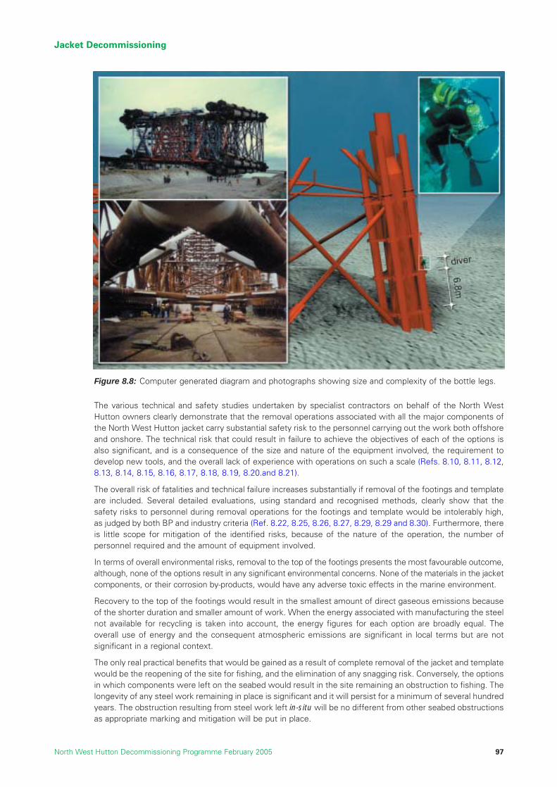
The various technical and safety studies undertaken by specialist contractors on behalf of the North WestHutton owners clearly demonstrate that the removal operations associated with all the major components ofthe North West Hutton jacket carry substantial safety risk to the personnel carrying out the work both offshoreand onshore. The technical risk that could result in failure to achieve the objectives of each of the options isalso significant, and is a consequence of the size and nature of the equipment involved, the requirement todevelop new tools, and the overall lack of experience with operations on such a scale (Refs. 8.10, 8.11, 8.12,8.13, 8.14, 8.15, 8.16, 8.17, 8.18, 8.19, 8.20.and 8.21).
The overall risk of fatalities and technical failure increases substantially if removal of the footings and templateare included. Several detailed evaluations, using standard and recognised methods, clearly show that thesafety risks to personnel during removal operations for the footings and template would be intolerably high,as judged by both BP and industry criteria (Ref. 8.22, 8.25, 8.26, 8.27, 8.29, 8.29 and 8.30). Furthermore, thereis little scope for mitigation of the identified risks, because of the nature of the operation, the number ofpersonnel required and the amount of equipment involved.
In terms of overall environmental risks, removal to the top of the footings presents the most favourable outcome,although, none of the options result in any significant environmental concerns. None of the materials in the jacketcomponents, or their corrosion by-products, would have any adverse toxic effects in the marine environment.
Recovery to the top of the footings would result in the smallest amount of direct gaseous emissions becauseof the shorter duration and smaller amount of work. When the energy associated with manufacturing the steelnot available for recycling is taken into account, the energy figures for each option are broadly equal. Theoverall use of energy and the consequent atmospheric emissions are significant in local terms but are notsignificant in a regional context.
The only real practical benefits that would be gained as a result of complete removal of the jacket and templatewould be the reopening of the site for fishing, and the elimination of any snagging risk. Conversely, the optionsin which components were left on the seabed would result in the site remaining an obstruction to fishing. Thelongevity of any steel work remaining in place is significant and it will persist for a minimum of several hundredyears. The obstruction resulting from steel work left in-situ will be no different from other seabed obstructionsas appropriate marking and mitigation will be put in place.
Jacket Decommissioning
North West Hutton Decommissioning Programme February 2005 97
Figure 8.8: Computer generated diagram and photographs showing size and complexity of the bottle legs.

The following table summarises the key qualitative and quantitative factors.
8.11 Recommended Decommissioning Option for the Jacket
On the basis of the above evaluation of the options using the technical, safety, environmental, societal andeconomic factors, it is recommended that the jacket should be removed down to the top of the footings atapproximately 100m below sea-level. The footings, integral template and damaged bracing will be left in-situ.
Recommendation: The North West Hutton jacket should be removed down to the top ofthe footings and returned to shore for reuse or recycling. The footings structure shouldremain in-situ.
Jacket Decommissioning
North West Hutton Decommissioning Programme February 200598
Criteria Full Removal Removal footings
Safety Probability of a fatality No. of lost time injuries
14% 16
13% 15
5% 6
Environmental Impact Energy (Household equivalents) CO2-E (Household equivalents) Footprint - km2 Persistence -Years
6,600
6,400
None None
7,300
6,800
<0.01 >500
7,100
5,900
<0.01 >500
Societal Impacts on fisheries UK Employment - man years
None
196
No-go fishing area
Not studied
No-go fishing area
66
Technical Probability of a major technical failure
45%
70%
23%
Economic See Section 13
Partial Footings Removal to Top of
Table 8.3: Summary of key qualitative and quantitative factors for three jacketremoval options.

References
8.1 Amoco (UK) Exploration Company, North West Hutton Platform, Inspection and Repair Status,September 1982.
8.2 “Report TEC 05” North West Hutton Jacket Information Package.
8.3 “Report TEC 27” AKER KVAERNER, North West Hutton, Comparative Assessment Study (Jacket DamageIdentification & Drill Cutting Removal), Document No. 8226-NWH-ST-16, Rev 01, 22nd December 2003.
8.4 Petroleum Act 1998.
8.5 1998 Ministerial Meeting of the OSPAR Commission, Sintra, Portugal on 22 – 23 July 1998, OSPARDecision 98/3, Date of Adoption 1998, Sintra.
8.6 “Report TEC 06” North West Hutton, Alternative Removal Methods, June 2003.
8.7 Atkins, North West Hutton Jacket Decommissioning Study, Document No. CL4521-ER-01, Issue 01,September 2002.
8.8 Joint Industry Project (JIP), Single Lift Concepts Summing Up, DNV Report No. 2001 -0553 Rev 02.
8.9 “Report TEC 25” Altair Engineering, Investigation of Jacket Lifting and Footings Options for North WestHutton Decommissioning, Document No. BPABD-29-03-R-01, Rev 0, 25th June 2003.
8.10 “Report TEC 02A”, Heerema Marine Contractors, North West Hutton, Substructure DecommissioningComparative Assessment Detailed Removal Method, Document No. GI100-Rp01, May 2003.
8.11 “Report TEC 02B”, Saipem UK, North West Hutton Decommissioning Study Year 2003 RefreshmentStudy Report, Document No. 973000-NWH 2003-001.
8.12 Sasp Offshore Engineering UK, North West Hutton Decommissioning Study, Document No. 540039-02-LE-70002, Rev B, 9th March 1999.
8.13 Saipem, North West Hutton, Decommissioning Study, Supplementary Study Report, Document No.979924-REP-1001, Rev 01, 15th November 1999.
8.14 HEEREMA Marine Contractors, North West Hutton, Platform Removal Feasibility Study, Document No.E/1018 (2205), Rev 2, 29th October 1999.
8.15 Seaway Heavy Lifting, Removal and Transportation Methodology for North West Hutton Topsides andJacket Upper Sections Study, Document No. SHL.47.450.GM-011, Rev C, 1st November 1999.
8.16 “Report TEC 04A”, Noble Denton, Europe Ltd, North West Hutton Platform – Independent ComparativeAssessment of Partial and Total Jacket Removal, document No. A4113/NDE/MGB/1, Rev. 1, 4th July 2003.
8.17 “Report TEC 04B”, Global Maritime, North West Hutton, Jacket Removal study for Complete or PartialRemoval, Document No. GM-22875-0703-14708, Rev 0, 2nd July 2003.
8.18 “Report TEC 09” Decommissioning Technology Forum, Task Force Industry Study, Jacket Removal,July 2003.
8.19 “Report TEC 028A”, Stolt Offshore, Feasibility Study for the Bottle Leg Removal of North West HuttonPlatform, Document No. MEC-066-041, Rev 3.0, 27th November 2003.
8.20 “Report TEC 028B”, Technip-Coflexip, North West Hutton Jacket Decommissioning Leg Cutting Review,Document No. UK003771-7001, Rev C, 5th December 2003.
Jacket Decommissioning
North West Hutton Decommissioning Programme February 2005 99

8.21 “Report TEC 28A”, Stolt Offshore, Removal of the North West Hutton Platform – Overview of the SubseaOperations, Document No. MEC-066-040, Rev 1.0, 14th November 2003.
8.22 “Report SAF02C”, Risk Support, North West Hutton, Quantitative Risk Assessment of the Removal ofthe North West Hutton Jacket – BP Model, Rev 2, 23rd July 2003.
8.23 “Report TEC 26”, TECHNIP – COFLEXIP, North West Hutton Drilling Template & Mud Line BraceDecommissioning, Rev 1, 4th July 2003.
8.24 Oil and Gas Guidance Notes for Industry Decommissioning of Offshore Installations and Pipelinesunder the Petroleum Act 1998, Published by Offshore Decommissioning Unit, Department of Trade andIndustry, 21 August 2000.
8.25 “Report TEC 29”, COWI, Quantative Comparative Assessment of Jacket Removal Options, DocumentNo. P-058983-A-100, Issue No. 2, 26th March 2004.
8.26 “Report SAF 01A” Heerema Marine Contractors, North West Hutton Decommissioning HazardIdentification, Review & Assessment, Rev 2, April 2003.
8.27 “Report SAF 01B” Saipem UK, North West Hutton, Decommissioning Study Year 2003 RefreshmentStudy Report, Document No. 973000 – NWH 2003-001.
8.28 “Report SAF 02A” Risk Support, Quantitative Risk Assessment of the Removal of the North West HuttonJacket – HMC’s Procedure , Rev 3, 15th July 2003.
8.29 “Report SAF 02B” Risk Support, Quantitative Risk Assessment of the Removal of the North West HuttonJacket – Saipem’s Procedure, Rev 2, 16th July 2003.
8.30 “Report SAF 07A” DNV, North West Hutton Independent Review of Jacket Removal HAZIDs and QRAs,Rev 03, 24th September 2003.
8.31 “Report ENV01”, Environmental Statement in support of the De-commissioning of the North WestHutton Facilities, Report No. BPX067/ES/2003, Version 3, March 2004.
8.32 “Report ENV 02”, Energy and Emissions Report for the Decommissioning ofNorth West Hutton.
8.33 “Report TEC 01”, Corrpro Companies Europe Ltd, North West Hutton, Life Assessment of JacketFootings, Rev 0, 19th September 2003.
8.34 “Report SOC 01”, SFF Services Ltd, North West Hutton, Decommissioning Fisheries Overview.
8.35 “Report SOC 02”, DTZ Pieda Consulting, North West Hutton Decommissioning Economic ImpactReport, Reference: 02/09188, June 2003.
8.36 Coull, K.A., Johnstone, R and Rogers S.I. (1998), Fisheries Sensitivity Maps in British Waters, UKOOA Ltd.
8.37 Weight Estimated by BP based on Heerema Marine Contractor’s Drawing No. HR-126-00-1, Rev A, dated15th October 1999, Removal Sequence North West Hutton Jacket and Footing.
Jacket Decommissioning
North West Hutton Decommissioning Programme February 2005100

9 DRILL CUTTINGS
9.1 Introduction
This section describes the options for decommissioning the North West Hutton cuttings pile as a discreteentity, and evaluates them within the framework of the guiding principles discussed in Section 6. In orderto provide a clear appreciation of the advantages and disadvantages of different options, any potentialeffects of the presence of the North West Hutton jacket are disregarded for the purposes of this evaluation.This section presents:
• an outline history of the pile and a description of its present composition and effect on thesurrounding seabed;
• descriptions of possible options for decommissioning the pile;
• an evaluation of the technical, safety, environmental, societal and cost implications of these options;and
• a recommended option for decommissioning the drill cuttings pile.
9.2 Present Composition, Condition and Effects of the North West Hutton Drill Cuttings Pile
9.2.1 Introduction
This section gives further information about the history and physical nature of the drill cuttings pile and of thesurrounding seabed that have an important bearing on the various options that could be used todecommission the pile.
9.2.2 History
The wells at North West Hutton were drilled to a depth of about 3,300m below the level of the seabed, and theresulting rock cuttings were treated on the topsides before being discharged to sea under licence, as wascommon industry practice at that time (Sections 4 and 5). A total of 53 wells and partial wells (commonlyreferred to as “sidetracks”) were drilled at North West Hutton, with the last well being drilled in 1992.
Drill cuttings are formed as the drill bit creates the hole. The cuttings are generally small in size, typically lessthan 0.5cm in diameter and irregular in shape. The cuttings are removed from the well by a fluid referred toas “drilling mud” or “drilling fluid”, and carried back to the topsides where they are cleaned to remove excessdrilling fluid. On North West Hutton, and other installations, the cleaned cuttings were then discharged intothe sea from caissons. The cuttings fell to the seabed where a large proportion of the cuttings, including anyremaining coating of drilling fluid, accumulated as a pile on the seabed directly beneath the platform.
The North West Hutton wells were drilled with two types of drilling fluid (Refs. 9.1 and 9.2). The uppersections (down to around 1,000m) were drilled with a water-based fluid, but for the lower sections, an oil-based fluid was used. At the time, oil-based fluids were widely used to control difficult drilling conditions suchas those encountered at North West Hutton. The North West Hutton pile will therefore have formed withdiscrete layers of water-based and oil-based cuttings. Although samples of the pile show differentcompositions, there is, however, no detectable evidence of such layering within the pile.
The size, extent and composition of the pile were summarised in Sections 4 and 5. Because of the waterdepth at the North West Hutton location, which results in very low wave action at the seabed and generallyweak seabed currents, the pile lies largely within the confines of the jacket legs. It is elliptical in shape, withits long axis running NE-SW, and has a maximum diameter of approximately 200m (Figure 9.1) (Ref. 9.1).
Drill Cuttings
North West Hutton Decommissioning Programme February 2005 101

As the cuttings were discharged and settled on the seabed, the irregular size and shape created voidsbetween the cuttings particles (like pebbles on a beach) which filled with seawater. As the cuttings particleswere compressed in the presence of the seawater and further deposition of cuttings added weight, some ofthis water was squeezed out, but a significant amount remains entrained or trapped within the pile. It isestimated that approximately 45% of the pile (by volume) consists of seawater trapped between the solidparticles (Refs. 9.4 and 9.5). As a result of this high proportion of water, the pile is relatively weak; it has a low“shear strength”. Consequently, the pile tends to slump and has a relatively flat profile, attaining a maximumheight of 5.5m above the seabed (Figure 9.2). Using side-scan sonar images, the volume of the drill cuttingspile, including the volume of seawater, has been calculated to be 30,000m3.
Drill Cuttings
North West Hutton Decommissioning Programme February 2005102
137.5
Seabed elevationm below LAT
138.0
138.5
139.0
139.5
140.0
140.5
141.0
141.5
142.0
142.5
143.0
143.5
144.0
144.5
Limit of survey data
PlatformNorth
N
Structure shown is plan on lowest horizontal framework at -144.30m
Assumed extent of pile for in-situ covering
Source: Aker Kvaernerbased on Brown & Root 1992 survey
144
143
142
141140
139
Figure 9.1: Contour map of the North West Hutton drill cuttings pile (Ref. 9.3).

9.2.3 Composition
The present composition of the pile was shown in Section 5, Table 5.6. This data has been derived from theanalysis of samples taken from the pile and surrounding area during numerous seabed surveys.
9.2.4 Physical Nature of the Drill Cuttings Pile
The upper surface of the pile is in contact with seawater, and a thin layer here (about 0.5cm thick) isexposed to an aerobic environment. The concentrations of hydrocarbons and some other contaminants inthis layer have been decreasing (Refs. 9.1 and 9.4) since discharges ceased, as a result of naturalweathering caused by physical processes such as current and wave action, bio-degradation by bacteria, andby bioturbation by seabed organisms.
The water depth, low temperature (approximately 4 C) and very low energy levels from wave and currentaction in the vicinity of North West Hutton result in this upper, “recovering”, layer remaining in a stablecondition. This in turn indicates that there is very little leaching or transfer of hydrocarbons and other materialfrom deeper layers of the pile into the surrounding environment.
The leaching rate will depend on a number of factors including conditions for weathering and disturbance ofthe pile, but industry studies applied to North West Hutton pile suggest that the total leach rate of oil from thepile is 2-3 tonnes per annum (Ref. 9.1). The relatively low leach rate is consistent with observations of the pileand also modelling results that provide estimates of the likely persistence of an undisturbed pile.
There is some anecdotal evidence that the recovered layer can, in places, form a fragile ‘crust’ that may reducethe movement of material out of the pile, although it is not strong enough to protect the pile against physicalimpact. Contaminants are therefore predominantly contained within the pile, but if the surface layer weredisturbed, material would be released; the amount of material released would depend on the size and natureof the disturbance. Once the source of the disturbance is removed, the aerobic conditions at the new surfaceor interface rapidly weather the material and form a new aerobic surface layer (Figure 9.3).
Drill Cuttings
North West Hutton Decommissioning Programme February 2005 103
137.5
Seabed elevationm below LAT
138.0
138.5
139.0
139.5
140.0
140.5
141.0
141.5
142.0
142.5
143.0
143.5
144.0
144.5
North
West East
South
Vertical scale 2x exaggerationHorizontal scale, metres
100806040200
Figure 9.2: Cross section through the North West Hutton drill cuttings pile (Ref. 9.5).

9.2.5 Understanding of the North West Hutton Drill Cuttings Pile and the Surrounding Area
A total of seven major sampling and survey programmes (Table 3.2, Section 3.4) plus additional opportunitiesfor analysis have been conducted on and around the North West Hutton cuttings pile since 1983 to assessand monitor the nature of the pile and its effects on the marine environment (Refs. 9.1 and 9.4). Thesesurveys, which have extended up to 10km from the platform, provide a comprehensive picture of the extentof the pile’s impact on the seabed and the ongoing natural recovery processes.
The presence of cuttings material, and its effects on the environment, can be measured in a number of ways.
9.2.5.1 Hydrocarbons and Benthic Communities
Typically, the presence of hydrocarbons (for oil-based drill cuttings piles such as that at North West Hutton)and the presence of barium in the form of “barite”, can be used as “markers” for the presence of drill cuttingsmaterial. The presence of hydrocarbon concentrations in excess of 50ppm has been demonstrated to be anaccepted threshold above which benthic communities are affected (Ref. 9.1). Figure 9.4 shows the reductionin hydrocarbon concentration with time and distance from the platform. This shows that small amounts ofdrilling material, evidenced by raised hydrocarbon levels, were detectable between 2,500m and 5,000m fromthe platform in 1985. (It is important to note that at these distances the impact of other installations and activitymay also be affecting the results). The detection of hydrocarbons at these sampling points is most likely to bedue to very fine material being carried by the current as the cuttings were originally discharged (Ref. 9.6).
9.2.5.2 Diversity Indices
In general, increasing hydrocarbon concentration is likely to lead to a reduction in the number of speciespresent in seabed (benthic) communities. The effects of the presence of drill cuttings are detected bysampling the seabed communities at different distances from the cuttings pile and comparing these withcommunities from similar but uncontaminated areas of seabed.
The Shannon-Wiener diversity index is a way of expressing complex data on the numbers of species presentand their density per unit area in a single figure. It is used to describe the composition of the seabedcommunities and to illustrate how these have been affected by the platform’s operations.
Normal undisturbed sites in the central and northern North Sea often have diversity index values of over5, but in severely disturbed areas, such as those adjacent to accumulations of oily cuttings, the index canbe less than one.
Figure 9.5 shows the recovery in the diversity of the benthic species to typical background levels in relationto time and distance from the platform, to typical background levels.
Drill Cuttings
North West Hutton Decommissioning Programme February 2005104
Hydrodynamic Forcing
Erosion and settling - response to hydrodynamic forcing
Seabed Substrate
Anoxic Cuttings
Aerobic
Anaerobic
Degradation
Oxic Cuttings
Recolonisation& Bioturbation
Currents
Oil Migration /Release
Figure 9.3: Schematic of cross-section of generic cuttings pile showing themain features and processes on and in a large drill cuttings pile.

Figures 9.4 and 9.5 provide a clear indication of how the area around the North West Hutton cuttings pile hasrecovered and how the recovery has progressed with time since drilling operations ceased in 1992. At sitesmore than 400m from the platform the diversity of benthic faunal communities has returned to typical levels.It is anticipated that the recovery will continue, but it is likely to slow significantly as the recovered zoneapproaches the main drill cuttings pile around the platform. This is because the recovery processes takesignificantly longer in the main pile itself due to replenishment of hydrocarbons from within the pile, and theabsence of biodegradation in material below the aerobic surface layer (Refs. 9.1 and 9.7).
Drill Cuttings
North West Hutton Decommissioning Programme February 2005 105
Seabed Surveys
1985: 2500-5000m
1999:1200- 2500m
2002:800m
Recovery- 50ppm HC contour retreating with time
Figure 9.4: Diagram indicating reduction in hydrocarbon concentration with timearound North West Hutton.
Figure 9.5: Chart indicating improvements in species diversity with time aroundNorth West Hutton.
Sh
ann
on
-Wie
ner
div
ersi
ty v
alu
e
Distance from North West Hutton (m)
7
3
4
5
6
1
2
0
50 100
150
200
250
300
400
500
600
800
1200
2500
5000
7500
1000
0
1992
1997
1999
2002
An important finding from these surveys of the pile and surrounding area is that material from the undisturbedpile is not spreading and affecting the surrounding seabed in the recovered zone.
9.2.5.3 Barium
Barite is a widespread and naturally occurring mineral used to add weight to drilling fluids. Bariumconcentrations decrease with distance from the platform and by 5km from the pile they are at levels typicalof background for this area of the North Sea (Ref. 9.6).
9.2.5.4 Trace Contaminants
Trace contaminants including polychlorinated biphenyls (PCBs) and alkylphenol ethoxylates (APEs), commonlyknown as endocrine disruptors, have also been detected in and around the pile. PCBs decrease with distancefrom the platform, from 7ppb at 200m to <0.1ppb at 5000m. PCB values in the North West Hutton cuttings pileare similar to those reported as part of the UKOOA JIP (Joint Industry Project) Phase II programme (Ref. 9.13).
Nonylphenol (a breakdown product of APE) is present in variable concentrations (880-120,000ppb) on thecuttings pile but at lower concentrations by 500m (12ppb) (Ref. 9.6).
The possible presence of LSA (low specific activity) scale in cuttings discharged from North West Hutton wasevaluated in radiochemical surveys in 1992, and these indicated that none is present (Ref. 9.6).
9.2.5.5 Food Chain Effects
Additional work conducted under the JIP on drill cuttings concluded that undisturbed drill cuttings piles arepredicted to have negligible effects on the food chain. The UKOOA report (Refs. 9.8 and 9.9) also concludedthat disturbing the pile could cause a local fish-kill but such effects would not be carried up the food chainto higher organisms.
9.3 Assessment of Decommissioning Options for the Drill Cuttings Pile
As stated in Section 6 “Principles”, the intent of the evaluations of the decommissioning options for the NorthWest Hutton jacket and drill cuttings has been to ensure that the identification of appropriate options for thesetwo components is not biased or adversely affected by the obvious inter-relationship between them.
Options for dealing with drill cuttings piles, such as that present at North West Hutton, have been examinedin considerable detail by the UK and Norwegian oil and gas industry. The results and guidance prepared byUKOOA represents the fullest appreciation of this complex subject, gathered from an exhaustive series oftechnical and environmental studies (Ref. 9.8).
The UKOOA studies concluded that there are several decommissioning options, grouped in three broadcategories - Natural Degradation; Covering; and Retrieval - which are realistic and feasible for large cuttingspiles in deep water. Each possible option presents a different set of technical, safety, environmental, societaland cost issues.
The assessment studies for the North West Hutton drill cuttings pile reviewed a wide range of optionsidentified for dealing with the issue (Ref. 9.5). A total of six methods, each of which can be broadly includedin the three main categories listed above, were screened by the project for the North West Hutton cuttingspile. Of these, two were excluded in the screening and four were taken forward for detailed evaluation; anadditional option, “Excavation”, was added because of the particular location and circumstances of the NorthWest Hutton pile. The results of the screening exercise are summarised in Table 9.1. Each of the short-listedoptions is described and evaluated in detail in Sections 9.4 to 9.7.
Drill Cuttings
North West Hutton Decommissioning Programme February 2005106

9.4 Option “Leave in-situ to degrade naturally”
9.4.1 Description
As stated earlier, this section evaluates options for the cuttings pile as a stand-alone entity, in order to provide abalanced assessment based on issues related only to the drill cuttings pile. The “leave in-situ” option could onlybe achieved, however, if the bottle-legs and the lower bracings of the jacket were left in place on the seabed.
Natural degradation, as the name suggests, would involve leaving the pile in its present location to continuerecovery by natural processes. The processes of weathering and bio-degradation by marine organisms wouldcontinue to slowly reduce the concentration of hydrocarbons in the cuttings.
9.4.2 Technical Feasibility
This option would not require any operations to be conducted on the pile and there are therefore no technicalchallenges. A programme of monitoring would be developed to assess the condition of the pile from time totime, to ensure that it remains stable, that recovery continues and there is no impact on the surroundingseabed. The scope, frequency and duration of such a programme would be commensurate with the knownand predicted significance of the impacts of the pile.
9.4.3 Environmental Impact
9.4.3.1 Zone of Effect on Seabed
Since drilling ceased in 1992, the area of adjacent seabed affected by elevated concentrations of hydrocarbonhas decreased in size as described above. It is predicted that this recovery will continue as the outer marginof the cuttings pile, less than 20cm thick, bio-degrades and slowly mixes with natural seabed sediment (Ref.9.7). The area of seabed exhibiting physical, chemical and biological perturbation as a result of the presenceof the pile will also decrease with time. It is estimated that the rate of recovery will slow as the recoveredzone encroaches on the main body of the pile. At this stage, the recovery will reach equilibrium and althoughrecovery will be continuing, the pile will appear to be stable for a significant period time (Ref. 9.7).
Drill Cuttings
North West Hutton Decommissioning Programme February 2005 107
Table 9.1: Possible decommissioning options for the North West Hutton drill cuttings pile.
Category Description of option Discussion
NaturalDegradation
Cover
Retrieval
Leave in-situ to recover naturally.
Enhanced Bio-degradation.
Excavate cuttings to accessfootings.
Leave in-situ and cover with inertmaterial (Sand, gravel, rock).
Contained Aquatic Disposal.
Retrieve and re-inject offshore.
Retrieve and return to shore fortreatment and disposal.
Maintains the current status of the pile with noadditional disturbance.Section 9.4
Enhance the rate of bio-degradation by addingnutrients and oxygen and possibly heat. Option notpursued due to unproven technology and poorevaluation in the UKOOA drill cuttings JIP.
Added for consideration as the least technicallyonerous method of accessing the footings and otherseabed equipment.Section 9.6
Method to “seal” the cuttings pile in its presentcondition using conventional offshore technology.Section 9.5
Transferring the cuttings to a “dredged pit” close tothe existing location and covering them. Option notpursued as it is impractical on this scale.
Requires the cuttings to be lifted to surface, treatedand then re-injected together with associatedvolumes of seawater into new wells at the presentlocation or existing wells elsewhere.Section 9.7
Requires the cuttings to be lifted to the surface andtransported onshore. The cuttings and seawaterwould then be treated and disposed of.Section 9.7
Key: An option short-listed for further evaluation

9.4.3.2 Release of Hydrocarbons
The pile itself is stable; the upper surface has formed an aerobic layer of recovered material, which crusts inplaces and may provide some degree of protection against physical disturbance. Hydrocarbons are presentlyleaching from the surface of the pile at a low rate, estimated to be around 2 -3 tonnes per year (Ref. 9.1). Theannual input of hydrocarbons to the sea from this slow release is very small and generally insignificant inoverall terms, although the additive and undesirable nature of all inputs is recognised. Many such releasesoccur as a result of natural discharges from the seabed, and the marine ecosystem has the capacity to bio-degrade small localised inputs, with no observable effects on the wider environment.
9.4.3.3 Movement of Material from the Pile to Adjacent SeabedIf the pile were left unprotected at its present location, it is likely that it would experience very minor physicaldisruption from currents, extreme wave action, and external sources such as fishing gear and anchor chains.This would result in the short-term re-suspension of cuttings and hydrocarbons into the water column (Ref.9.7).
Trials and studies of this minor re-suspension behaviour have shown that the disturbed material rapidly returnsto the seabed at or close to the original location (Ref. 9.8). All such disturbances have been shown to affectthe pile superficially at the areas of contact. The material from such disturbance will therefore cause nosignificant or detectable spreading of the affected zone. Any cuttings exposed to seawater by the removal ofthe surface of the pile would biodegrade and a new aerobic layer would form rapidly.
9.4.3.4 Predicted Long-term Persistence
One of the important parameters when considering the leave in-situ option is the time required for the pile tobio-degrade completely. Using a computer model developed as part of the UKOOA investigation, detailedmodelling studies were undertaken to estimate how long the pile would exist if left to recover naturally at theNorth West Hutton site (Ref. 9.7). Over the long-term, the extent and volume of the pile would be influencedby several factors, particularly gradual biodegradation, occasional extreme wave and current action, andoccasional physical disruption by fishing gear. Modelling studies show that the combination of these factorswould result in a gradual decrease in the volume of the pile with time. The modelling results indicate that thepile would be likely to persist for between 1,000 and 5,000 years, and it is recognised that uncertainties in themodel could result in a longer duration (Refs. 9.1 and 9.7). Although the model results have a wide range ofuncertainty, the longevity predicted by the model is consistent with the slow release of hydrocarbon from thepile, and the results of the surveys that indicate that the pile is very stable and that all the constituents areeffectively “locked in” to the pile unless they are disturbed by natural forces or intervention.
9.4.4 Societal Impact
9.4.4.1 Potential Impacts on Commercial Fisheries
During consultation, some stakeholders expressed the concern that the long-term presence of hydrocarbonsand other contaminants in the pile could lead to contamination of fishing gear and tainting of fishing catches,which in turn could adversely impact commercial fishing activities in the area. Commercial fishing has beencarried out around the North West Hutton platform throughout its operational life, including the period whenthe “footprint” of the cuttings pile attained its maximum extent, and there have been no recorded instancesof fishing gear contamination or tainting of catches during this period. Fish have been caught from these areasand no problems or issues have been reported in relation to these catches or indeed from other similar areasof the North Sea. In addition, studies by UKOOA have shown that species of fish caught close to cuttings pileshave about the same level of hydrocarbon and other contaminants in their tissues as fish caught in the opensea away from platforms (Ref. 9.9). No evidence of tainting has been found in fish caught in close proximityto platforms. It is therefore unlikely that fish caught around a cuttings pile would exhibit any characteristicsaffecting the subsequent commercial sale.
9.4.4.2 Potential Impacts on Fishing Activity
Fishing over the pile itself would only be possible if the jacket footings were removed. Evidence from fieldtrials suggests that trawling over cuttings piles creates minimal disturbance, and there is no evidence thatfishing gear is damaged or contaminated as a result (Ref. 9.8).
Drill Cuttings
North West Hutton Decommissioning Programme February 2005108

9.4.4.3 Presence of Hydrocarbons
Monitoring, modelling and industry studies indicate that under normal circumstances hydrocarbons wouldleach or escape from the pile into the water column at a very low rate (2-3 tonnes per year) (Ref. 9.1). Studiesshow that the input of this quantity of oil to the water column over the course of a year, and its subsequentdispersal and bio-degradation, would be unlikely to cause any visual or ecological impacts.
9.4.5 Safety of Personnel
There would be no activities associated with decommissioning the pile and therefore no direct safety risk topersonnel. Periodic surveys undertaken as part of the long-term monitoring programme would represent a lowlevel of risk for personnel on survey vessels.
9.5 Option “Leave in-situ and Cover with Inert Material”
9.5.1 Description
To achieve this decommissioning option, the pile would be covered by layers of inert material designed tofurther stabilise the pile and prevent the low levels of hydrocarbon release described above. The coveringmaterial would be placed by a surface vessel designed specifically for “rock dumping” activities to protectand stabilise sub-sea structures. The initial cover would be a layer of coarse sand and fine gravel, overlainwith layers of gravel and armour stone. The layer of armour stone would minimise the risk of nets snaggingon the covered pile, and the risk that bottom-towed fishing gear would remove material from the pile cover.The covering technique would require transportation of sand, gravel and rocks from an onshore quarry anddepositing these in a series of layers on top of the cuttings pile. Material would be accurately placed overthe pile using a “fall-pipe vessel” specially designed for similar activities, for example placing gravel andsmall rocks to protect pipelines and other equipment on the seabed (Figure 9.6). Studies have indicated thatabout 90,000m3 of material would be required to cover the North West Hutton pile, creating a structure witha maximum height of approximately 9m above the seabed and covering an area of seabed slightly largerthan the existing pile which is about 0.02km2. It is estimated that the programme to install the cover wouldtake 10-14 weeks (Ref. 9.5).
Drill Cuttings
North West Hutton Decommissioning Programme February 2005 109

Drill Cuttings
North West Hutton Decommissioning Programme February 2005110
Figure 9.6b: Computer graphic of operations to cover the drillcuttings pile with footings in place.
Figure 9.6a: Computer graphic of operations to cover the drillcuttings pile with footings removed.

9.5.2 Technical Feasibility
Several detailed studies have shown that it would be possible to cover the pile with a protective layer designedto seal and protect the pile from disturbance. The cover would be stable under wave, current and trawlingloads although some disturbance and break-up of the cover is inevitable with time (Ref. 9.5). Although anyproposed cover design would be thoroughly reviewed and risk-assessed prior to installation, there is a risk thatthe deposited material would sink into the pile itself and cause some disturbance and redistribution of pilematerial. Such an occurrence would not cause major problems although it may result in a technical failure ofthe cover to provide the intended “seal” properties of the covered pile.
The installation of the cover is effectively an irreversible operation and therefore it is difficult to envisage howthe previous status could be restored in the event that a problem develops.
9.5.3 Environmental Impact
9.5.3.1 Disturbance of the Cuttings Pile during Placement: The fall pipe vessel can place material accuratelyalthough the activity of depositing dense gravel and rock from the surface to the seabed in 140m of waterwould result in energy being transferred to the cuttings pile. This activity would inevitably lead to thedisturbance and re-suspension of material into the water column, particularly in the early stages of theoperation. In reality, the effects of such disturbance, whilst undesirable, are likely to be relatively small andlead to minor impacts that would be localised and short-lived (Ref. 9.1).
9.5.3.2 Leaching of Contaminants: Oil is estimated to be leaching from the uncovered pile at the rate of about 2-3 tonnes a year (Ref. 9.1). The cover would be designed to effectively seal in all the contaminants. It is thereforeassumed that the rate of leaching from the covered pile would be close to zero.
9.5.3.3 Long Term Fate of the Pile: The contents of the pile would effectively be sealed, and there wouldessentially be no exchange between the pile and the surrounding environment. Consequently, biodegradationwould proceed at an even slower rate than that predicted for the uncovered pile left in-situ. Bearing in mindthe intended design of the cover, and the longevity of the pile if left uncovered (Section 9.4.3.4), a covered pilewould, in effect, be a permanent feature on the seabed that exhibited little or no change with time.
9.5.4 Societal Impact
9.5.4.1 Impacts on Other Users of the Sea:If the pile were protected by a contoured over-trawlable cover, itwould not present an impediment to normal fishing operations (Ref 9.5). In the absence of any residualstructural items from the platform, the area of seabed covered by the pile could then be accessed safely bycommercial fishing vessels.
9.5.4.2 Short- and Long-Term Environmental Impacts: Some stakeholders expressed concerns regarding thepotential for environmental impacts caused by the construction of the cover, long-term leaching, and slowbreakdown of the cover. These have been discussed under “environmental impact”, Section 9.5.3.
9.5.4.3 Employment: Quarrying material and building the cover would use existing facilities and technologies.Although involving a reasonably large amount of sand, gravel and rock, this activity would have a relativelyminor and short-term impact by supporting existing employment and is unlikely to be a stimulus for anysignificant new employment or commercial opportunities (Ref 9.10).
9.5.5 Safety of Personnel
Rock dumping is a relatively well-understood procedure utilising established techniques and equipment.Consequently, the associated risks are known and can be managed and mitigated to the extent that the overallrisk is considered low.
The offshore risks associated with covering the drill cuttings pile fall predominantly into general occupationaland vessel risks. The technology, although large in scale, is relatively straightforward and is such that failureswill generally result in delay and hence increased risk due to an increase in the duration of the project.
The increased activity associated with installing the rock cover on the cuttings pile would result in an overallincrease in safety risk for those involved in the operation. It is estimated that the risk of fatality (PLL) for coveringoperations conducted after the footings had been removed would be less than 0.6% (Refs. 9.11 and 9.12).
Drill Cuttings
North West Hutton Decommissioning Programme February 2005 111
9.6 Option “Excavate and Disperse” the Drill Cuttings
9.6.1 Description
The term “excavate” in this document refers to the operations required to remove the drill cuttings fromaround the base of the structure, to expose the lower members of the structure and disperse the drill cuttingsaway from the immediate vicinity of the jacket. It is an option that could be used to access the footings shouldthis be required as part of the jacket removal programme.
Excavation could be carried out using hydraulic removal or dredging systems deployed remotely (Ref. 9.5).Material would be moved from the pile and deposited in the local area where it would disperse and then settleonto the adjacent seabed. Various types of equipment are available to implement such operations.
9.6.2 Technical Feasibility
Seabed sediments are routinely excavated by a variety of methods, including water-jetting, suction hoses andhydraulic dredgers. Operations significantly larger in scale than those that would be required for the NorthWest Hutton drill cuttings pile are routinely implemented for construction activities by other industries, andalso in seabed mineral recovery operations. Apart from the location, weather issues and the presence ofobstructions there appear to be no major technical obstacles to such an operation.
9.6.3 Environmental Impact
9.6.3.1 Impacts of Excavation
Moving the cuttings in this manner would result in the dispersal of the present pile, which has a relativelycompact shallow-peaking geometry, and the creation of a relatively flat feature on the surrounding seabed.Modelling shows that the mixture of seawater and cuttings particles would disperse in the near-bottomcurrents and settle over an area considerably larger than that covered by the present pile.
Consequently, areas of seabed that have now recovered, or are in the process of recovering, from the impactof the original discharge of cuttings, would become re-contaminated. This re-contamination would be moresevere, and would occur over a shorter period of time, than that which resulted from the original discharge.The excavation and dispersal of pile material would be completed over a period of about 10 weeks, whereasthe periodic discharge of cuttings during drilling took place over several years. Excavation of a pile of this sizemay require regulatory approval.
9.6.3.2 Impacts of Re-distributed Cuttings
Studies conducted during the UKOOA drill cuttings initiative have indicated that the hydrocarbons and othermaterial within cuttings piles are effectively bound to the solids. It is therefore unclear if the excavation andre-deposition of the North West Hutton cuttings pile would result in the release of significant quantities of oilinto the water column. It is not possible to predict how much oil might be released or if the quantities wouldbe sufficient to cause even a minor sheen or slick on the sea surface.
Excavating and re-depositing the cuttings as a more widely spread layer would result in the exposure of alarger proportion of the pile to aerobic conditions. This would result in a greater environmental loading ofhydrocarbons and other material. Modelling studies indicate that the redistributed pile would bio-degrade morequickly than the pile left in-situ. This more rapid recovery would be offset by a corresponding increase in therate of release of material into the surrounding environment.
9.6.4 Societal Impact
Some stakeholders expressed concerns that if excavation were to result in significant re-contamination ofareas of the seabed that had recovered, and an increase in the rate of release of hydrocarbons, then thissolution would be less acceptable to society than other solutions.
Drill Cuttings
North West Hutton Decommissioning Programme February 2005112

9.6.4.1 Impacts on Other Users of the Sea
During excavation operations, it is likely that the existing 500 metre exclusion zone would remain in place andthat, in addition, a guard vessel would be deployed to ensure the safety of other sea users in the vicinity.
As for the longer term, the potential impact on commercial fishing is considered to be the main issue. Thereare no studies which specifically investigate the results of fishing over an excavated pile. However, evidencefrom field trials suggests that trawling over cuttings piles generally creates minimal disturbance, and there isno evidence that fishing gear is damaged or contaminated as a result. It is therefore likely that the more widelyspread layer of drill cuttings created by the excavation operations would not have a long-term impact oncommercial fishing activity (Ref. 9.5 & 9.8).
9.6.4.2 Economic Benefit
The expenditure involved in excavation operations would provide a short-term benefit to companies involvedin such subsea activity, but there are no long-term sustainable economic or employment benefits apparentfrom this work (Ref. 9.10).
9.6.5 Safety of Personnel
Excavation of the pile would be carried out by a support vessel equipped with the appropriate remotely operatedsub-sea excavation systems. Such an activity would employ equipment with a relatively well-understoodmethod of operation and there are no adverse safety implications associated with the use of such equipment.The risks associated with excavation are similar to those of rock dumping, in that the majority of risks areoccupational and vessel-related. The risk of a fatality is estimated to be less than 0.5% (Refs. 9.11 and 9.12).
9.7 Option “Retrieve and Dispose of Cuttings Onshore or by Re-injection Offshore”
9.7.1 Description
These options require the retrieval of the cuttings from the seabed, followed by either re-injection offshore orreturn to shore for treatment and disposal. Several different systems could be used for retrieval, including anROV-deployed hydraulic dredging system or a retrieval system deployed from a more traditional dredgingvessel. Material could be stored on the retrieval vessel or transferred to another vessel for transportation tothe shore or reinjection site. For onshore disposal, the cuttings would be treated to remove excess water, torecover oil for possible re-use, to treat other contaminants, and prepare the residual solid material for onshoredisposal. The offshore retrieval operation would take several months and could extend over two summerseasons (Ref. 9.5).
Drill Cuttings
North West Hutton Decommissioning Programme February 2005 113

9.7.2 Technical Feasibility
9.7.2.1 Offshore Retrieval and Shipment
A small-scale drill cuttings retrieval trial was completed on North West Hutton during 2001 as part of the UKOOAdrill cuttings programme – phase 2 (Ref. 9.8). The trial indicated that it is technically feasible to recover cuttingsto the surface albeit with a substantial volume of entrained seawater that is required to physically lift the cuttings.A full-scale retrieval of a cuttings pile has never been attempted and would present a substantial technical riskdue to the scaling-up of the operations, and the associated difficulties identified during the pilot trial.
Any retrieval operation on North West Hutton would be undertaken in the presence of the jacket footings. Theretrieval rates of any equipment deployed would therefore be restricted to 10-50 m3/hr of material, because oftechnical and operational restraints. The studies and the trials have indicated that the minimum volumes ofseawater that would be retrieved with entrained cuttings would be six times the volume of cuttings, and theoptimum average achievable would be between 10 and 20 times (Ref. 9.8). Any retrieval operation wouldtherefore have to handle and dispose of between 300,000m3 and 600,000m3 of contaminated seawater, inaddition to approximately 30,000m3 of cuttings pile material. Dealing with such quantities would presentsignificant challenges, and there would be risks associated with the intensive operations required to handle,transport, store and treat these materials.
A retrieval operation could not practically guarantee removal of all the cuttings material. This is because ofthe technical difficulties of retrieval, and the lack of ability clearly to distinguish between the cuttingsmaterial and the seabed.
9.7.2.2 Re-injection
UK and international law does not presently allow lifting and re-injection of material such as historic drillcuttings piles. It would be technically feasible to re-inject the cuttings either from a drilling rig located close tothe North West Hutton site or from a suitably equipped fixed installation at another site. It has been assumedthat the full waste stream recovered (i.e. all the cuttings and seawater) would have to be re-injected. Re-injection at the North West Hutton site would involve drilling at least two new wells with a mobile drilling rig,and re-injecting the cuttings at a depth of at least 5-6,000ft below the seabed. Re-injection at another operatingplatform would be technically feasible, but is unlikely to be practical and is currently not available (Ref. 9.5).
Drill Cuttings
North West Hutton Decommissioning Programme February 2005114
C A
B
1
A
B
C
1
Hydraulic Dredging Unit
Pump Unit
Workclass ROV
Recovery
Figure 9.7: Computer graphic of example of a system to retrieve drill cuttings fordisposal onshore or re-injection.

The possible future disposal of the drill cuttings pile by re-injection was reviewed as part of the overall decisionto cease production at North West Hutton. Given the ongoing legal uncertainty surrounding the lifting and re-injection of historic drill cuttings piles, the evaluation showed clearly that drilling new wells would be morecost-effective than retaining platform wells together with all the associated safety systems.
9.7.2.3 Onshore Treatment and Disposal
There is no existing plan or experience for disposing of recovered cuttings onshore. “Fresh” cuttings fromongoing operations are treated effectively in a process known as thermal desorption which uses heat toextract and recover the oil leaving the solids to be sent to landfill. In the case of the recovered cuttings fromNorth West Hutton the slurry (cuttings and water) would be put through a separation process (hydrocycloneor shaker) and the solids and liquids would be separated. The solids (plus small amounts of residual water)would then be treated by thermal desorption and the hydrocarbon would be recovered. Liquids would betreated and discharged under consent. Solids would be likely to be classified as hazardous waste and so wouldbe disposed of to a hazardous waste landfill. The hydrocarbons may be suitable for reuse or may have toundergo further specialist treatment.
No existing plant or treatment site has the capacity to deal with the large volumes of watery waste, with itsinherently variable contaminant loading, that would be generated during such a programme. A new treatmentplant would have to be designed and constructed.
9.7.3 Environmental Impact
9.7.3.1 Offshore Retrieval and Shipment
During the retrieval operations, a proportion of the pile material would escape into the water column. Somematerial would not be fully recovered by the system, and progressively deeper layers of the pile, containingun-degraded cuttings material, would be exposed as retrieval continued. Both types of event would result inoil and contaminated solids being released into the water column in the form of a plume. Oil from this plumemight cause small surface slicks from time to time, depending on the rate of retrieval and the type of materialbeing recovered. Parts of the adjacent seabed would be affected by the settlement of disturbed cuttings.
9.7.3.2 Re-injection
A minimum of two new disposal wells would have to be drilled if the cuttings were to be re-injected at theNorth West Hutton site. This would create a range of relatively small impacts offshore that are well understoodand managed. Injection at an existing facility may be able to use existing, redundant wells, in which case fewadditional impacts would arise.
9.7.3.3 Onshore Treatment and Disposal
A total of 300,000m3 to 600,000m3 of seawater contaminated with hydrocarbons and other material wouldhave to be separated from the recovered slurry, treated and then discharged under licence from the onshorereception or treatment facility. Thermal desorption treatment would cause few impacts, although care wouldhave to be taken during the transportation and storage of untreated material. Treated material is likely to beclassified as hazardous, and would have to be disposed of to landfill site designated for such material. Existinghazardous waste sites in the UK are in high demand and using them for the disposal of bulk residual drillcuttings would impact on this resource (Refs. 9.1 and 9.5).
9.7.3.4 Energy Use
All the retrieval and disposal options are highly energy-intensive because of the extensive use of marinevessels, and the treatment of cuttings onshore. Data on the energy-use of each option is presented in Table9.2 in Section 9.9.
Drill Cuttings
North West Hutton Decommissioning Programme February 2005 115

9.7.4 Societal Impact
9.7.4.1 Other Users of the Sea
During retrieval and disposal operations, it is likely that the existing 500 metre exclusion zone will still bein place. In addition, a guard vessel would be deployed to ensure the safety of other sea users in thevicinity of the operations.
As for the longer term, the potential impact on commercial fishing is the main issue. Since field trials suggestthere is no evidence that fishing gear is damaged or contaminated as a result of trawling over cuttings piles,retrieval and disposal of the North West Hutton cuttings pile would not have a significant positive impact oncommercial fishing activity (Ref. 9.5).
9.7.4.2 Economic Benefit
All the “retrieval and disposal” options are relatively expensive, and they would provide a short-termcommercial benefit to specialist companies involved in both the offshore and the onshore activities, resultingin the support of existing employment for the duration of the retrieval and disposal operations. However, thereappear to be no significant long-term sustainable benefits from these options and studies indicate they wouldnot result in the creation of permanent jobs (Ref. 9.10).
9.7.4.3 Use of Onshore Resources
Any disposal of the cuttings onshore would make a noticeable demand on the available UK sites for thedisposal of hazardous waste. There are indications that the landfill directive will greatly reduce the availabilityof hazardous waste storage space and the disposal of cuttings residue would represent a major burden onthe system. Further environmental and social impact studies would be required at the stage when potentialonshore landfill locations were identified to assess impacts on communities and amenity value.
9.7.4.4. Stakeholders
Some stakeholders have expressed the view that the ‘precautionary principle’ should be used to address thisissue – in other words that the best approach would be the removal and disposal of the cuttings pile. Howeversome other stakeholders have cautioned against distributing the pile because of concerns over redistribution ofpile material and the impact this would have on the environment. The generic ‘legacy’ issue of how North Seadrill cuttings piles should be regulated and managed in the future is the subject of ongoing OSPAR discussion,and BP will monitor developments in this area for relevance to the North West Hutton drill cuttings pile.
9.7.5 Safety of Personnel
Cuttings retrieval and disposal offshore or onshore would use existing techniques and equipment, in a large-scale programme never before attempted in the North Sea. It is likely that the cuttings could be recoveredremotely without the requirement for divers.
Drilling and re-injection into new disposal wells, re-injection at an offsite location, and disposal onshore are allrelatively standard offshore operations with known hazards and associated risk (Refs. 9.11 and 9.12).
The overall risk of this option is, however, relatively high when compared with the other options for thecuttings pile, because of its duration and the large number of personnel that would be required. Duringretrieval of the cuttings significant operational risk will exist as a consequence of the need for simultaneousmultiple vessel activity within the North West Hutton field.
The risk of a fatality in the sub-options described above therefore ranges from 2.2% (for onshore disposal) to6.4% (for re-injection). These values are significantly higher than those for the leave in-situ options, whichrange from 0.17% to 0.55% (Refs. 9.11 and 9.12).
Drill Cuttings
North West Hutton Decommissioning Programme February 2005116

9.8 Cost Assessment
The following section discusses the estimated costs for implementing the options for the drill cuttings pile.The implications of long-term monitoring of the site are discussed in Section 18.
The estimated cost for leaving the drill cuttings in-situ is £0.5m for the long term monitoring of the site.
The cost of covering the cuttings was estimated to be in the region of £8 million.
Excavation of the cuttings would cost between £8 million and £9 million.
The costs for lifting the cuttings and disposing of them by re-injection or on land are similar. Both are subjectto significant uncertainty because of the technical and environmental risks discussed above. The costs forthese options are estimated to range from £43 million to £114 million.
9.9 Comparative Assessment of Options for the Drill cuttings Pile
This section draws together the findings from Sections 9.4 –to 9.7, and presents a comparative assessmentof the options for decommissioning the cuttings pile. The options reviewed are:
1. Leave in-situ without treatment, which is only achievable if part of the footings is left in place.
2. Cover with an inert layer, which is only achievable if part of the footings is left in place.
3. Excavate and disperse.
4. Retrieve and re-inject.
5. Retrieve, and treat and dispose onshore.
The study work carried out specifically for North West Hutton, and supported by a large body of general workcarried out on drill cuttings, suggests the following:
• Cuttings piles in-situ on the seabed introduce material into the marine environment but they remainstable in the absence of significant disturbance from natural or man-made sources.
• Large scale disturbance of a pile would lead to a significant increase in the short-term environmentalloading of cuttings material in the vicinity of the pile.
• Retrieval operations could remove some or all of the material, but although feasible are a significanttechnical challenge that would be highly energy-intensive and create significant environmental andsafety risks associated with transport, handling and long-term storage.
The extensive sampling and study work conducted on the North West Hutton cuttings pile indicates clearlythat a significant degree of natural recovery has occurred on the seabed around the pile since drilling ceasedin 1992. The pile is very stable because of the low current speeds and wave action in the area, and will remainso in the absence of significant man-made disturbance.
It is clear from the study work that there are two main outcomes for dealing with the drill cuttings that involveeither leaving the cuttings on the seabed at or near the present location to recover by natural processes, orremoving some or most of the cuttings from the present location for disposal elsewhere. In general, thetechnical and safety issues associated with the removal processes are significantly greater than those for theleave in-situ cases because of the complexities of accessing, lifting, handling, treating and disposing of largevolumes of cuttings and associated seawater.
The environmental aspects of the evaluation are somewhat more complicated to assess. The leave in-situoptions would result in the contents of the pile remaining in the marine environment. The rate of recovery andhence the rate of release of the contents from the pile is dictated by the action taken on the pile. Moving thepile on the seabed by mechanical means would result in a faster natural recovery of the pile material, but areasof the seabed presently exhibiting low levels of contamination would become re-contaminated by suchactivity. Alternatively, covering the pile should contain the material and essentially prevent the release ofcontaminants, and hence increase the overall recovery time.
Drill Cuttings
North West Hutton Decommissioning Programme February 2005 117

Operations to retrieve the pile would have offshore and possibly onshore impacts. During retrieval, a volumeof seawater 10-20 times the volume of the pile volume recovered would become contaminated, and wouldhave to be treated prior to disposal. The retrieval operation would also result in the redistribution of pilematerial into the surrounding water and seabed as a consequence of both physical disruption and the removalof the recovering aerobic surface layer which would expose the un-recovered material beneath.
Retrieving some or all of the pile material would have the benefit of directly removing a significant proportionof the material from the present offshore location, and this would allow the site to recover more quickly. Themain disadvantage of retrieval, from an environmental viewpoint, would be the creation of a sizeable newwaste stream that would have to be transported, treated, stored and disposed of. The relocation of thisvolume of material for handling onshore would impact significantly on the treatment site and also on theutilisation of hazardous waste landfill, in addition to the requirement to deal with the large volume of seawatereither by treatment or discharge. It is also clear from the studies that the amount of energy and otherresources that would be required to complete the removal would be far in excess of the energy value of thehydrocarbon and other material contained within the pile itself. Although these aspects are not directlycomparable, they do provide an indication of the proportionality of the activity and also the complexity ofimplementing the overall evaluation.
Disposal by re-injection would alleviate the environmental concerns associated with onshore treatment but isnot permitted under UK or International Law. A re-injection operation on this scale has not been attemptedbefore, however, and therefore carries a risk of failure that could lead to unanticipated environmentalconsequences. As with onshore disposal, the energy and resources required to implement this option do notappear to be proportional to the benefits achieved by removing some or all of the pile.
From a societal perspective, the main issue regarding the options of natural recovery is the impact on fishingactivity. Numerous studies of the effects of cuttings piles on fish and fishing activity have demonstrated thatthere are no significant effects, although the concerns of the fishing industry over the potential for tainting offishing gear and fishing catches are acknowledged. It is therefore considered that there would be some impacton fishing activity by leaving the pile in-situ but that this would be minor.
A decision to retrieve the pile would result in short-term economic benefits due to the expenditure associatedwith the operations. Studies indicate that there is little opportunity for sustainable new industries or sectorsas a result of a retrieval operation.
Disposal of the material by re-injection would have little adverse societal impact with the exception of short-termdisruption to other users of the sea caused by the presence of a drilling rig at the re-injection location. Onshoredisposal would, however, result in some onshore disruption and possibly significant nuisance as a result ofincreased vehicle activity and, in particular, the utilisation of scarce hazardous waste landfill resources.
From a cost or economic perspective the leave in-situ options have significantly lower overall costs and lesseconomic risk than the removal options. The leave in-situ costs range from £0.5m to £8m compared to a rangeof £43m to £114m for the retrieval options. It should also be noted that the retrieval costs are subject tosignificant uncertainty, because of the nature of the operations involved.
Drill Cuttings
North West Hutton Decommissioning Programme February 2005118

The following table attempts to summarise the key qualitative and quantitative factors.
Notes1. Energy is expressed in terms of the average energy use of UK households. In 2001 the average
energy use was 80GJ, and the average CO2–E emissions in 2000 was 6 tonnes.
2. For Energy and CO2 figures in tonnes and GJ see Environmental Impact Statement.
9.10 Recommended Decommissioning Option for the Drill Cuttings Pile.
There are clearly positive and negative aspects to each of the options evaluated for decommissioning thecuttings pile. On the basis of a thorough assessment and evaluation of all the data, it is recommended thatthe North West Hutton cuttings pile should be left in place to recover naturally. This is also the bestenvironmental option.
The main drivers for this course of action are the clear evidence that the pile remains very stable and that thenatural recovery processes result in only minor inputs of hydrocarbons and contaminants to the marineenvironment. The pile would exist at its present location for a very long time and would represent a minordisturbance to commercial fishing activity.
Removal of the pile would speed the recovery of the seabed at the site, but the environmental impacts, thesafety and technical risks, and the costs of the required operations are not proportional to the benefits thatwould be gained by removal.
Drill Cuttings
North West Hutton Decommissioning Programme February 2005 119
Table 9.2: Summary of options for decommissioning the drill cuttings pile.
Criteria
Technical Risks
Safety (Probabilityof Fatality)
EnvironmentalImpactEnergy(households)
CO2–E(households)
General
Persistence
Societal Issues
Economic
Leave in-situ
No material risks
0.17%
80
80
Minor impact ofnatural recoverymechanisms.Affected areadecreasing
1,000- 5,000 years
Minor Impact onfishing activity
0.5
Cover & Leave
Low overall risk ofimplementation.Some risk of failingto meet long termdesign intent
0.55%
900
900
Minor impact ofnatural recoveryMechanisms.Cover will reduceor eliminaterecovery process.
Indefinitely
Minor impact onfishing activity
8
Excavate & Leave
Low overall risk ofimplementation
0.48%
400
400
Significantspreading ofmaterial ontoadjacent seabed.Covering areagreater than originalpile
<1,000 – 5,000years
Minor impact onfishing activity
9
Recover & Re-inject
Moderate technicalrisks associatedwith retrieval anddisposal
6.4%
3.500 (onsite)3,800 (offsite)
3,200 (onsite)3,500 (offsite)
Potential for minor /moderatespreading ofmaterial ontoadjacent seabed.More rapidrecovery ofaffected area
N/A
Minor economicbenefit due toincreased activity
43-110
Recover &Dispose Onshore
Moderate technicalrisks associatedwith retrieval,onshore treatmentand disposal
2.2%
5,300
29,000
Potential for minor /moderatespreading ofmaterial ontoadjacent seabed.More rapidrecovery ofaffected area.Potentialenvironmentalimpacts attreatment anddisposal sites.
N/A
Minor economicbenefit due toincreased activity.Dis-amenity due toonshore treatmentand landfill usage.
46-114

Debris clearance and ongoing monitoring will be an integral part of the long-term option to leave the drillcuttings in place. BP will also continue to be involved in industry research investigating the best techniquesfor managing drill cuttings piles, including the UKOOA Joint Industry Project, and will monitor futurediscussions and decisions under the OSPAR framework for their relevance to the North West Hutton pile.These studies and decisions will be taken into account in any decisions concerning the ongoing managementof the drill cuttings pile at the North West Hutton field location.
Recommendation: The North West Hutton drill cuttings pile should be left in place torecover naturally.
References
9.1 “Report ENV 01”, Environmental Statement in support of the De-commissioning of the North WestHutton Facilities, Report No. BPX067/ES/2003, June 2004.
9.2 “Report ENV 02”, Energy and Emissions Report for the Decommissioning of North West Hutton 2004.
9.3 Brown & Root Survey, 1992, North West Hutton Drill Cutting Survey – Survey Report. Report by Brownand Root Survey Ltd, Aberdeen, to Amoco (UK) Exploration Co. November 1992.
9.4 “Report ENV 05”, BMT Cordah Ltd, Analysis of Samples Collected from Cuttings Pile at North WestHutton by ROV, July 2003, Document No. BPX54/NWH/04, 2004.
9.5 “Report TEC 11/12”, Dredging Research Ltd, Technical Review of the Options of Covering, Relocation,CAD, and Recovery for Onshore Treatment of the North West Hutton Drill Cutting Pile, Document No.296.UK.0303.1, Rev 0, June 2003.
9.6 “Report ENV 08”, BMT Cordah Ltd, Long Term Trends in Seabed Disturbance around the North WestHutton Platform, Document No. BPX54/NWH/04, 2004.
9.7 “Report ENV 04”, BMT Cordah Ltd, North West Hutton Cutting Pile Modelling, Document No. 28000/01,March 2004.
9.8 UKOOA Drill Cutting Initiative, Final Report, February 2002.
9.9 UKOOA, Drill Cuttings Initiative Food Chain Effects Literature Review, Report by University of Wales –Bangor, Continental Shelf Associates Inc (UKOOA Drill Cuttings JIP, Phase 2 follow up reports).
9.10 “Report SOC 02”, DTZ Pieda Consulting, North West Hutton Decommissioning Economic ImpactReport, June 2003.
9.11 “Report SAF 03 & 04”, Risk Support Ltd, Quantitative Risk Assessment of Options for Recovering DrillCuttings, Rev. 2, 18th July 2003.
9.12 “Report SAF 07B”, DNV, North West Hutton, Independent Review of Cuttings HAZIDs and QRAs, Rev 2,25th September 2003.
9.13 Characterisation of the Cuttings Piles at the Beryl ‘A’ and Ekofisk 2/4A Platform – UKOOA Phase II, Task1, Rogaland Research, 29th October 2001.
Drill Cuttings
North West Hutton Decommissioning Programme February 2005120

10 PIPELINES
10.1 Introduction
This section presents the results of the assessments that were carried out to determine the appropriatedecommissioning programmes for the North West Hutton gas and oil pipelines. These pipelines are no longerrequired (Section 4) and no potential commercial use can be foreseen for them in their present locations. Bothof these pipelines are about 13km long, the 10” gas line, PL 147 is trenched and the 20” oil line PL 148 is un-trenched. The two pipelines are discussed separately in this section, which:
• Describes the techniques that could be used to decommission the pipelines.
• Describes the pipelines and summarises their histories.
• Describes their present condition, and the cleaning that has been carried out before anydecommissioning programme is implemented.
• Discusses the approach and method that was used to select the decommissioning option for each pipeline.
• Identifies the potential decommissioning options for each pipeline.
• Assesses technical feasibility, safety risks, environmental impacts, societal impacts and costs of eachoption. The methods used to assess these different criteria are the same as those used for the otherNorth West Hutton facilities (Section 6).
• Recommends a decommissioning option for each pipeline.
To assess the advantages and disadvantages of the options for each pipeline, a comparative assessment wascarried out which addressed all of the issues identified in the DTI Decommissioning Guidelines, namely:
• the present condition and degree of burial of the pipelines;
• the potential impact in the marine environment of carrying out any of the decommissioning options;
• the energy use of each option;
• the potential impact on users of the sea if the pipelines were left in place; and
• the rate of deterioration of the pipelines if left in place, and their possible future effects on theenvironment as they deteriorate.
10.2 Applicable Techniques for Decommissioning the Pipelines
The main decommissioning options for the pipelines can be separated into two broad categories, namely;leave in-situ or remove and return to shore. Several alternative options and methods of implementation arepossible within these broad categories. The following section gives a brief description of different techniquesthat could be used to decommission North West Hutton pipelines PL 147 and PL 148.
10.2.1 Pipelines Left in-situ
10.2.1.1 Selective Removal
This technique is used when some parts of a pipeline are buried and some exposed. To render the pipelinecompletely buried, the exposed parts are removed by cutting out sections and taking them to shore forrecycling. The cut ends of pipe are then buried in the natural sediment, so that the entire length of theremaining pipe is left buried.
10.2.1.2 Rockdumping
Aggregate, usually from an onshore quarry, is transported offshore in a rock-dumping vessel and then carefullyplaced over selected areas of the line, using a “fall pipe”. In this way a low mound of aggregate is built up,covering the pipe and creating a profile over which trawling gear may be towed unhindered. The exposedsections of a partially buried pipeline could also be covered by “selective rock-dumping” using the same system.
10.2.1.3 Trench and Bury
In this technique, a trench is dug either alongside or beneath the pipeline, and the line is laid into it (Figure10.1). The trench can then be backfilled with the sediment that was removed from it, or it may be left tobackfill naturally as a result of currents and wave action.
Pipelines
North West Hutton Decommissioning Programme February 2005 121

10.2.2 Techniques for Removing Pipelines
10.2.2.1 “Reverse S lay” and “Reverse J lay”
These are two techniques for pulling the pipe to the surface after it has been separated from the platform orpipeline to which it was connected. Both methods require the use of a specialist pipe-laying vessel or bargewhich is anchored over the pipeline, and then moves along the route of the pipeline recovering the line as itprogresses. One end of the pipe is pulled up to the vessel by a wire. In S-lay, the pipe is cut and recoveredfrom a horizontal position on the deck, whereas in J-lay, the pipe is held vertically at surface, and the cutsections are lifted off by crane (Figures 10.2 and 10.3). In both methods, sections of pipe between 12m and24m long are cut off, transferred to an adjacent cargo barge and taken to shore for recycling.
10.2.2.2 “Cut and Lift”
In this technique, remote or diver-assisted mechanical methods or “hot cutting” techniques are used to cutthe pipe into sections on the seabed. These 12m or 24m long sections would then be lifted to the surface bythe crane on the support vessel, and stored on cargo barges for transportation to the shore (Figure 10.4).
Pipelines
North West Hutton Decommissioning Programme February 2005122
Figure 10.1: Trench and bury technique.

10.3 Decommissioning the 10” Gas Line PL147
10.3.1 Items to be Decommissioned
10.3.1.1 Materials and Inventory
The gas line is a trenched, 10” diameter pipe which runs from North West Hutton to a junction with theNinian pipeline called the Ninian Tee (Figure 10.5). It comprises approximately 2,400 tonnes of steel pipe andconcrete coating (Section 5). Constructed in 1982, it was originally used to export gas from North WestHutton to the St Fergus gas terminal via the FLAGS pipeline. As production at North West Hutton declined,however, there was insufficient gas from the field to meet the platform’s requirement for fuel gas, and sothe pipeline was re-commissioned in 1994 to import gas from the Ninian Central platform through the NinianFuel Gas Pipeline System.
Pipelines
North West Hutton Decommissioning Programme February 2005 123
Figure 10.2: “Reverse S lay” recovery technique.
Figure 10.3: “Reverse J lay” recovery technique.
Figure 10.4: “Cut and lift” recovery method.

The pipeline extends from the North West Hutton platform to the flexible line (“spool piece”) at the Ninian Teetie-in. The North West Hutton owners own the pipeline from the North West Hutton platform to its connectionwith the Ninian Tee, including the 6” diameter 250m long flexible tie-in spool (Figure 10.5). The followingequipment will be removed and returned to shore for recycling:
• The 6” flexible spool piece at the Ninian Tee.
• The SSIV, control umbilical and other associated equipment.
• The redundant Welgas Tee pipeline and tie-in spool from the export tie-in (PL 147) to the Western Leggas pipeline (PL 17) see note below.
• All loose items including bridges, mattresses and supports.
The Western Leg Gas Pipeline PL 17 is operated by Shell and still in operation. Only the disused Welgas Teepipeline and tie-in spool associated with the North West Hutton will be removed and returned to shore forrecycling (as part of PL 147).
Pipelines
North West Hutton Decommissioning Programme February 2005124
Figure 10.5: North West Hutton pipelines including detail of Ninian Tee.

10.3.1.2 Burial Status
The 10” gas pipeline lies in a trench approximately 0.8m deep with the top of the pipe nominally 0.45m belowthe level of the surrounding seabed. The trench was designed to fill naturally with seabed material andadditional rock dumping was undertaken to protect certain sections of the pipe. The trench over time hasnaturally back filled although some minimal exposure still remains.
The depth of soil covering the pipe within the trench ranges from 0 to 1.0m and is typically 0.2m. A typicalcross section of this soil covering is illustrated in figure 10.6a, which shows the original design intent of beingtrenched to 800mm.
Regular inspections have been performed using a Remotely Operated Vehicle (ROV) deployed from a surveyvessel. The pipeline is classed as exposed whenever it is visible within the trench. Since the pipeline is trenchedany exposed pipe remains below mean seabed level. Recent surveys show that any exposures have been largely‘crown’ exposures i.e. the very top of the pipe being exposed, see figure 10.6b, or the top half of the pipe.
In addition to the natural backfill, rock was placed at some locations to correct free-spans within the trench.This is where the pipe was not resting on the bottom of the trench when it was installed and this gap, or span,was filled to support the pipe. This was done for operational reasons and to prevent overstressing of the pipe.
The overall burial trend from 1993 to 2001 is shown in table 10.1. The results of these surveys clearly indicatethat the total length of exposed pipeline is gradually decreasing, indicating continued self burial of the line. Theexposed length of the line has reduced from 100% when installed in 1982 to 26.6% (3475m) when lastinspected in 2001.
Pipelines
North West Hutton Decommissioning Programme February 2005 125
800m
m
450m
m
200mm
Bottom of Trench
Mean Seabed Level
371mm 0
800m
m
450m
m
Bottom of Trench
Mean Seabed Level
371mm 0
Exposed pipe visible
Rock berm
Figure 10.6a: Typical Cross Section showing natural backfill.
Figure 10.6b: Crown of pipe exposure.
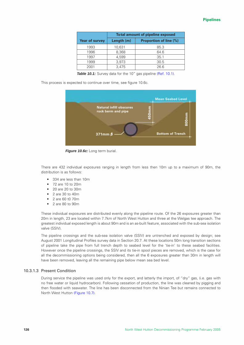
This process is expected to continue over time, see figure 10.6c.
There are 432 individual exposures ranging in length from less then 10m up to a maximum of 90m, thedistribution is as follows:
• 334 are less than 10m• 72 are 10 to 20m• 20 are 20 to 30m• 2 are 30 to 40m• 2 are 60 t0 70m • 2 are 80 to 90m
These individual exposures are distributed evenly along the pipeline route. Of the 26 exposures greater than20m in length, 23 are located within 7.7km of North West Hutton and three at the Welgas tee approach. Thegreatest individual exposed length is about 90m and is an as-built feature, associated with the sub-sea isolationvalve (SSIV).
The pipeline crossings and the sub-sea isolation valve (SSIV) are untrenched and exposed by design; seeAugust 2001 Longitudinal Profiles survey data in Section 20.7. At these locations 50m long transition sectionsof pipeline take the pipe from full trench depth to seabed level for the ‘tie-in’ to these seabed facilities.However once the pipeline crossings, the SSIV and its tie-in spool pieces are removed, which is the case forall the decommissioning options being considered, then all the 6 exposures greater than 30m in length willhave been removed, leaving all the remaining pipe below mean sea bed level.
10.3.1.3 Present Condition
During service the pipeline was used only for the export, and latterly the import, of “dry” gas, (i.e. gas withno free water or liquid hydrocarbon). Following cessation of production, the line was cleaned by pigging andthen flooded with seawater. The line has been disconnected from the Ninian Tee but remains connected toNorth West Hutton (Figure 10.7).
Pipelines
North West Hutton Decommissioning Programme February 2005126
Table 10.1: Survey data for the 10” gas pipeline (Ref. 10.1).
Year of survey Length (m) Proportion of line (%)
To tal amount of pipeline exposed
1993 10,631 85.31996 8,368 64.61997 4,599 35.11999 3,973 30.52001 3,475 26.6
800m
m
450m
m
Bottom of Trench
Mean Seabed Level
371mm 0
Natural infill obscures rock berm and pipe
Figure 10.6c: Long term burial.

Individual exposures are distributed evenly along the pipeline route. Of the 26 exposures greater than 20min length, 23 are located within 7.7km of North West Hutton and three at the Welgas tee approach.The greatest individual exposed length is 89.3m and is an as-built feature, associated with the SSIV. (SeeAugust 2001 Longitudinal Profiles survey data Section 20.7)
Depth of Exposure:
Where exposures occur, the extent varies from crown of pipe to full circumferential exposure. A typical crownexposure is illustrated in Figure 10.6. Almost all exposures are contained within the trench and are belowmean seabed level (see Section 20.7).
10.3.2 Description of Options for the 10” Gas Line PL147
The following section discusses the available options for decommissioning the gas pipeline PL 147.
10.3.2.1 Option 1: Leave in-situ – Trenched and Buried below the Seabed.
The pipeline would be disconnected from the North West Hutton jacket at the subsea spool-piece and thissection plus the SSIV and the flexible connection close to the Ninian Tee would be recovered. Divers or remotetechniques would then be used to ensure that the exposed ends of the pipeline were completely buried.
The line would then be left filled with seawater and allowed to further self bury. The whole pipeline routewould then be surveyed by ROV, and any items of debris would be removed. A trawler would then undertakea sweep of the route using bottom-towed gear, to confirm that no items of debris that might pose a risk toother users of the sea remained on the site.
The condition and burial status of the pipeline would then be monitored periodically by an inspection programme.
10.3.2.2 Option 2: Pipeline Removal and Onshore Disposal.
Studies have indicated that although a number of removal techniques are feasible, the “cut and lift”method is recommended for this situation (Ref. 10.1). This method would reduce the likelihood thatsignificant amounts of concrete coating would become detached from the pipeline and fall to the seabedduring the recovery operations.
The line would be disconnected as described above. Divers or remotely operated equipment from a supportvessel would then progressively cut the pipeline on the seabed. As most of the length of the pipeline iscurrently buried, it would be necessary to uncover the pipeline using subsea excavation or dredgingtechniques. Sections up to 24m long would be lifted by the support vessel crane onto cargo barges forsubsequent transportation back to the shore. After the whole line had been removed, the route would be
Pipelines
North West Hutton Decommissioning Programme February 2005 127
Seabed
EL +7.0m LAT
EL -10.0m LAT
North WestHutton
Tie-in Spool
KP13.028
10" x 6"Reducer
6" FlexibleSpool PieceSealine
SSIV - 1485
North West HuttonTopsides
Pig Trap (V-307)
LAT
ESDVXV-283
PSV574
PL 147Riser
CROSSINGComorant 'A'to Brent 'A'
16" Gas PipelineKP 13.010 PL-116 to Ninian Central
and Ninian Southern
disconnected
NORTH WEST HUTTONPLATFORM
PIPELINELIMIT
TO OPENDRAINS
PIPELINELIMIT
Figure 10.7: Schematic showing details of the 10” gas pipeline PL 147 (not to scale).

surveyed and any significant items of debris removed. A trawler would then undertake a sweep of the routeusing bottom-towed gear, to confirm that no items of debris that might pose a risk to other users of the searemained on the site.
All recovered material would be returned to an onshore location for reuse, recycling or as a last resort disposal.
10.3.3 Assessment of Options for the 10” Gas Line
10.3.3.1 Technical Feasibility
No major technical issues were identified with any of the decommissioning options for the 10” gas pipeline.Leaving the line trenched in-situ involves significantly less work than removing the line and therefore carriesless technical risk. The highest technical risks are associated with uncovering the line and lifting the pipelineto surface whilst minimising loss of material, particularly pipeline coating, to the seabed (Ref. 10.1).
10.3.3.2 Safety of Personnel
Remote techniques will be used wherever possible to implement the work scope for pipelinedecommissioning (Refs. 10.1, 10.2 and 10.3). It is probable that divers will be required for certain aspectsof the programme. The overall safety evaluation indicates that the safety risks associated with the leave in-situ, and the removal options are within acceptable limits; all the operations, whilst not routine, do have atrack record. Table 10.2 presents the risks to personnel during execution of the work for the various optionsfor pipeline PL 147.
The overall safety risk for personnel involved in the operations to remove the 10” gas pipeline is far higherthan in any of the leave in-situ options. This is due to the significant amount of activity involved in removal andin particular the hazards associated with cutting, rigging, and lifting operations.
10.3.3.3 Environmental Impacts
The overall potential environmental impacts associated with pipeline decommissioning activities areconsidered to be generally low (Ref. 10.4).
Short-term Impacts
For the option “leave buried” there may be some minor disturbance of seabed sediments when the ends ofthe pipe are disconnected.
In the “cut and lift” option, seabed sediments along the entire route would be disturbed because the pipewould have to be uncovered before it could be retrieved. Sediments would be removed by water-jetting, jet-prop or mechanical digger. For sections close to the jacket, it is possible that some drill cuttings could bedisturbed, with some minor release of oil and contaminated cuttings into the water column. The vessels woulduse fuels and produce combustion gases, and transportation on land to recycling sites would use fuel andproduce combustion gases. Recycling would require the removal of the concrete coating to allow access tothe steel. This could result in potential hazards and environmental impacts during lifting, cutting and disposalworks, although recycling the steel in the pipes would help conserve resources, but it is likely that the pipecoatings would go to landfill.
Long-term Impacts
All the decommissioning options for the 10” gas pipeline would result in the surface of the seabed being leftfree from obstructions.
Pipelines
North West Hutton Decommissioning Programme February 2005128
Decommissioning OptionPLL
Risk of fatality
Decommission in-situ with no remedial work 0.2%Decommission in-situ with remedial trenching & burial 0.2%Complete removal by “cut and lift” 1.9%
Table 10.2: Risks associated with the various decommissioning options for the10”gas pipeline PL 147.

In the option “leave buried”, the steel pipe would slowly corrode and then collapse, eventually leaving a thintrace of corroded metal and broken concrete completely buried in the sediment. Since the inside of the pipehas been cleaned there would be no release of hydrocarbons to sea. Studies indicate that the anodes wouldcease to provide cathodic protection after 35–40 years, and that the pipeline would persist for a period of about300 years as it slowly degrades and collapses (Ref. 10.1). Although these timescales cannot be accuratelypredicted and the pipeline may last longer, this has no material impact on the overall assessment.
Fuel would be used, and combustion gases released, during periodic inspections and potential remedialactivities but the amounts are insignificant in overall terms.
If the removal option were implemented, some sections of concrete coating may be lost during the recoveryprocess. These may be left on or in the seabed, although it is anticipated that cleaning sweeps would removeany significant items. No other long-term environmental impacts have been identified.
Onshore impacts will be limited to recycling issues (removal of concrete and recycling of steel) and short-termnuisance caused by transportation and the use of landfill sites for any material that cannot be recycled.
10.3.3.4 Societal Impacts on Other Users of the Sea
The pipeline is presently trenched and mostly buried. The ‘FishSafe’ system is designed to alert fishing vesselsto potential snagging hazards, and it requires spans of over 10m long and 0.8m above the seabed to bedisplayed on the system. There are currently no spans on this pipeline which require to be identified aspotential obstructions, and no such spans are anticipated in the future. The seabed along the route of PL 147is flat and very stable (Ref. 10.1) and it is very unlikely that a trawl board would interact with the line in itspresent state of burial. The use of a trawler to sweep the line will confirm this. There is no history of any majorincident or interaction between fishing gear and the pipeline resulting in damage or compensation claims.
If the whole pipeline were removed by “cut and lift”, the potential small safety risk to fishermen would be eliminated.
10.3.3.5 Cost Assessment
The estimated costs for each of the options for decommissioning the 10” gas pipeline PL 147 are discussed below.
To leave the 10” gas line PL 147 in-situ, trenched and buried the estimated cost is £3m (+ or – £0.3m) for theflushing, cleaning and disconnection work and the removal of identified equipment.
The incremental cost for any residual trenching or covering work is estimated at £2m (+ or – £0.2m).
The incremental cost for removing and disposing of PL 147 onshore is estimated to be £10m (+ or - £5m). Thiscost is based on un-burying the pipeline and removing it to the shore for recycling and disposal.
The estimated costs, approximately £0.25m, associated with the long-term monitoring of the site are includedin the costs for leave in-situ and the remedial trenching options.
10.3.4 Recommended Decommissioning Option for the 10” Gas Line PL147
The options for decommissioning the 10” gas pipeline have been assessed in terms of their technicalfeasibility, safety risk, societal impact, environmental impact and cost. There are no significant technical orsafety issues that constrain the selection of any option, but the increased risks associated with the removalof the line are significant. There are no significant environmental concerns associated with any option.
The main area of concern for the evaluation centres on the possible effects of the presence of the line, and inparticular future deterioration of the line and the potential risk this poses for fishing activity. Because the lineis buried, however, any such risks are negligible or non-existent.
The DTI Decommissioning Guidelines state that a decision on the appropriate depth of burial of pipelines willtake account of seabed conditions and other relevant factors and that the expected burial would be to aminimum depth of 0.6m above the top of the pipeline (Ref. 10.5). As stated earlier, PL 147 has been trenchedto a depth 0.45m below the seabed level and has self buried to give an average cover of 0.2m (Figure 10.6).The implications of this were reviewed and the recommended outcome is considered acceptable for thefollowing reasons:
1) The 0.6m guideline is a general guide for the UKCS based on variable seabed stability conditions. As ageneral rule, seabed stability in the deep water of the northern North Sea, where near-bottom currentspeeds are generally low, is significantly greater than other areas.
Pipelines
North West Hutton Decommissioning Programme February 2005 129
2) Numerous general and specific surveys of the North West Hutton pipelines confirm that the seabed is stable.
3) Operations to re-trench the line and backfill with sand or rock to achieve the 0.15m additional burialrequired to meet the 0.6m guide value would cause disproportional disturbance to the seabed andwould require the removal of existing material to gain access.
The overall conclusion and recommendation is that the trench and burial depth is adequate to ensure thefuture stability of PL 147
At the pipeline crossing additional precautions would be necessary. The pipeline will be cut and removed atthe crossing but this might be deferred until the other pipeline is decommissioned. However the mostappropriate course of action will be determined nearer the time and will be subject to agreement with thepipeline owners and the regulatory authorities.
The recommended option for the 10” pipeline PL 147 is to leave the line trenched and buried in-situ with noadditional remedial work required.
Recommendation: The gas pipeline PL 147 should be left in-situ as it is already trenchedand self burried over majority of its length. Ancillary and loose protective equipmentshould be removed.
10.4 Decommissioning the 20” Oil Line PL148
10.4.1 Items to be Decommissioned
10.4.1.1 Materials and Inventory
The 20” diameter concrete-coated, steel oil export pipeline runs for approximately 13km from North WestHutton to the Cormorant Alpha platform. BP is responsible for the whole pipeline from the North West Huttonplatform to its connection with the Cormorant Alpha riser, including the tie-in spool (Figure 10.8). It comprisesapproximately 5,200 tonnes of steel pipe and concrete coating (Section 5).
10.4.1.2 Burial Status
The 20” oil pipeline lies on the surface of the seabed, and is not trenched. The most recent survey, conductedin 2001, found that the pipeline was exposed for 99.8% of its length and had 4 spans more than 10m long. Allof the spans identified were less than 0.4m high which is well within the ‘Fishsafe’ height of 0.8m. Spans of0.8m above the seabed or higher are displayed as potential obstruction and snagging hazards for commercialfishing on the ‘Fishsafe’ system. The pipeline crosses over 3 other pipelines and control lines along its routeand these are protected by rock dump and concrete mattresses; their locations are shown in Figure 10.5.
10.4.1.3 Present Condition
The pipeline was used to export oil from North West Hutton and also the Hutton oil fields. On cessation ofproduction, the line was pigged and flushed from North West Hutton to Cormorant Alpha using deoxygenatedseawater dosed with cleaned biocide. A detailed programme of pigging and flushing continued until theconcentration of oil in the water received at Cormorant Alpha indicated that hydrocarbons had been removed.A maximum threshold of 40ppm of oil in water was set to determine that the line was sufficiently clean; inthe event a lower level of approximately 30ppm was actually achieved. Results from the pigging operation andinspection of the surface equipment provide assurance that all significant hydrocarbon material has beenremoved from the pipeline.
Pipelines
North West Hutton Decommissioning Programme February 2005130
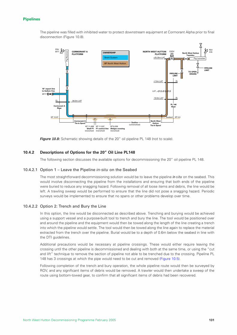
The pipeline was filled with inhibited water to protect downstream equipment at Cormorant Alpha prior to finaldisconnection (Figure 10.8).
10.4.2 Descriptions of Options for the 20” Oil Line PL148
The following section discusses the available options for decommissioning the 20” oil pipeline PL 148.
10.4.2.1 Option 1 – Leave the Pipeline in-situ on the Seabed
The most straightforward decommissioning solution would be to leave the pipeline in-situ on the seabed. Thiswould involve disconnecting the pipeline from the installations and ensuring that both ends of the pipelinewere buried to reduce any snagging hazard. Following removal of all loose items and debris, the line would beleft. A trawling sweep would be performed to ensure that the line did not pose a snagging hazard. Periodicsurveys would be implemented to ensure that no spans or other problems develop over time.
10.4.2.2 Option 2: Trench and Bury the Line
In this option, the line would be disconnected as described above. Trenching and burying would be achievedusing a support vessel and a purpose-built tool to trench and bury the line. The tool would be positioned overand around the pipeline and the equipment would then be towed along the length of the line creating a trenchinto which the pipeline would settle. The tool would then be towed along the line again to replace the materialextracted from the trench over the pipeline. Burial would be to a depth of 0.6m below the seabed in line withthe DTI guidelines.
Additional precautions would be necessary at pipeline crossings. These would either require leaving thecrossing until the other pipeline is decommissioned and dealing with both at the same time, or using the “cutand lift” technique to remove the section of pipeline not able to be trenched due to the crossing. Pipeline PL148 has 3 crossings at which the pipe would need to be cut and removed (Figure 10.5).
Following completion of the trench and bury operation, the whole pipeline route would then be surveyed byROV, and any significant items of debris would be removed. A trawler would then undertake a sweep of theroute using bottom-towed gear, to confirm that all significant items of debris had been recovered.
Pipelines
North West Hutton Decommissioning Programme February 2005 131
Seabed KP 0.0KP 12.07
Brent System
OWNERSHIP
BP North West Hutton
EL+7.0m LAT
+25.25m LAT
EL-10.0m LATEL -34.0m LAT
North WestHutton
Tie-in Spool
Cormorant ATie-in Spool Sealine
(untrenched)
North West HuttonTopsides
Pig Launcher
LAT
ESDV285
PSV576
PL 148Riser
NORTH WEST HUTTONPLATFORM
CORMORANT APLATFORM
PIPELINELIMIT
TO OPENDRAINS
PIPELINELIMIT
Cormorant ARiser
KP 11.699Shell P1
(trenched)
KP 11.537P1 control line(trenched)
KP 8.209Welgas crossing(trenched)
18" export lineto Sullom Voe
Pig
Rec
eive
r
PSV3017
Figure 10.8: Schematic showing details of the 20” oil pipeline PL 148 (not to scale).

10.4.2.3 Option 3: Pipeline Removal and Onshore Disposal
Studies have indicated that although a number of removal techniques are feasible, the “cut and lift”method is recommended for this situation (Ref. 10.1). This method would reduce the likelihood thatsignificant amounts of concrete coating would become detached from the pipeline and fall to the seabedduring the recovery operations.
The 20”pipeline would be disconnected as described above. Divers or remotely operated equipment from asupport vessel would then progressively cut the pipeline on the seabed. Sections up to 24m long would belifted by the support vessel crane onto cargo barges for subsequent transportation back to the shore. After thewhole line had been removed, the route would be surveyed and any significant items of debris removed. Atrawler would then undertake a sweep of the route using bottom-towed gear, to confirm that no significantitems of debris remained on the site. As with the trenching option, the pipeline crossings would have to bemanaged carefully as part of this process.
All recovered material would be returned to an onshore location for reuse, recycling or disposal.
Pipelines
North West Hutton Decommissioning Programme February 2005132
Existing Oil Line
Figure 10.9: Diagrams illustrating the process of trench and bury (Ref. 10.1).
Trench60
0mm
Trench and Bury

10.4.3 Assessment of Options for the 20” Oil Line
10.4.3.1 Technical Feasibility
There are no major technical issues identified with any of the decommissioning options for the 20” oil pipeline.
Leaving the line in-situ involves significantly less work than removing the line and therefore carries lesstechnical risk. The highest technical risks would be associated with lifting the pipeline to surface whilstminimising loss of material, particularly pipeline coating, to the seabed. Some degree of risk would beassociated with the trench and bury option because unanticipated seabed conditions (e.g. the presence ofboulders) or other relevant factors may be encountered which would cause operational problems. Sucheventualities are, however, considered to be unlikely; as other pipelines in the area have been trenchedsuccessfully (Ref. 10.1).
10.4.3.2 Safety of Personnel
Remote techniques will be used wherever possible to carry out the work. It is probable that divers will berequired for certain aspects of the programme. The overall safety evaluation indicates that the safety risksassociated with leave in-situ and pipeline removal are within acceptable limits since all the operations, whilstnot routine, do have a track record. Table 10.3 presents the risks associated with the various decommissioningoptions for PL 148 (Ref. 10.2 and 10.3).
The overall safety risk for personnel involved in the operations to remove the 20” oil pipeline is far higher thanin any of the leave in-situ options. This is due to the significant amount of activity involved in removal and inparticular the hazards associated with cutting, rigging, and lifting operations, and the onshore dismantling work.
10.4.3.3 Environmental Impacts
The overall potential environmental impacts associated with pipeline decommissioning activities are generallylow (Ref. 10.4).
Short-Term Impacts
In the option to leave the pipeline in-situ on the seabed, there are no identified environmental impacts apartfrom the physical presence of the line on the seabed. The line has been in position for over 20 years.
The trench and burial operations would disturb clean sediment and thus impact benthic communities in theimmediate vicinity of the present pipeline route. Small amounts of cuttings may be disturbed towards each endof the pipeline, and this may cause a local impact on the adjacent seabed. Any impact from such activity wouldbe relatively minor and last only a few months. The vessels involved in the work would cause a very localisedand transient impact on other users of the sea and give rise to localised atmospheric emissions due to fuel usage.
In the “cut and lift” option, seabed sediments along the entire route of the pipeline would be disturbed butthe short-term disturbance would be less than for the trench and bury option. For sections close to the jacket,it is possible that some oily cuttings could be disturbed, with some minor release of oil and contaminatedcuttings into the water column. The vessels would use fuels and produce combustion gases, andtransportation on land to recycling sites would use fuel and produce combustion gases. Recycling wouldrequire the removal of the concrete coating to allow access to the steel. This could result in potential hazardsand environmental impacts during lifting, cutting and disposal work, although recycling the steel in the pipelinewould have a positive environmental impact by conserving resources, but the energy saved by recycling wouldbe at least partially offset by the fuel used during the recovery of the line.
Pipelines
North West Hutton Decommissioning Programme February 2005 133
PLL Risk
Table 10.3: Risks associated with the various options for decommissioningthe 20” oil pipeline PL 148.
Decommission in-situ with no remedial work 0.21%Decommission in-situ with remedial trenching & burial 0.28%Complete removal by “cut and lift” 2.1%
Decommissioning Option

Long-Term Impacts
In the leave in-situ option, the pipeline would gradually deteriorate and eventually break-up. The corrosionproducts from the steel are benign and would not cause any significant environmental impacts. The concretecoating would most likely break-up and could potentially be spread from the pipeline location by trawlingactivity. Studies show that the anodes would cease to provide cathodic protection after about 35 - 40 years,and the pipeline could be present in the seabed for 300 years or longer, as the slow process of corrosion anddegradation continues (Ref. 10.1).
In the option “trench and bury”, the steel pipe will slowly corrode and then collapse in the manner describedabove. The trenching of the pipeline will, however, ensure that steel and concrete remained completely buriedin the sediment as the slow breakdown takes place.
Fuel would be used, and combustion gases released, during periodic inspections and potential remedial activities.
In the pipeline removal option, the seabed would be left clear of potential obstructions. It should be noted thatsections of concrete coating may be lost during the recovery process and these may be left on or in theseabed, although it is anticipated that cleaning sweeps would remove any significant items. No other long-term environmental impacts have been identified.
Apart from the possible nuisance associated with transportation and recycling activities, there would be verylittle onshore environmental impact. It is anticipated that the majority of material could be recycled, althoughit is possible that the concrete coating could be sent to landfill.
10.4.3.4 Societal Impacts on Others Users of the Sea.
If the pipeline were completely buried to a depth of 0.6m, the safety risk to fishermen would be eliminated.The seabed along the route of PL 148 is flat and very stable (Ref. 10.1) and it is very unlikely that a trawl boardwould interact with the line if it were buried as described. The use of a trawler to sweep the line will confirmthis. There is no history of any major incident or interaction between fishing gear and the pipeline resulting indamage or compensation claims.
If the whole pipeline were removed by “cut and lift”, there would be no safety risk to other users of the sea,and a very small area of seabed would once again be available for fishing operations.
If the pipeline were left in-situ, the steel would gradually corrode and the concrete coating would eventuallybreak up. Periodic surveys would be implemented to monitor the condition of the line, and remedial workswould be undertaken at this time to ensure the pipeline remained in a safe condition. Snagging hazardsrepresent a safety risk for the commercial fishing industry. It is also likely that debris from a deterioratingpipeline would be spread from the present route of the pipeline.
10.4.3.5 Cost Assessment
The estimated costs for each of the oil pipeline PL 148 options are discussed below.
To leave PL 148 in-situ on the seabed the estimated cost is £2m (+ or - £0.2m) for flushing, cleaning anddisconnection work.
The incremental costs for trenching and covering the pipeline is £1m (+ or - £0.1m).
The incremental cost for recovering and disposing of PL 148 onshore is £7m (+ or -£3.5m). This wide range isattributed to the possible use of new technology, weather conditions and technical challenges associated withseabed and soil conditions.
The estimated costs, approximately £0.25m, associated with long-term monitoring of the site are included inthe costs for the leave in-situ and remedial trenching options.
Pipelines
North West Hutton Decommissioning Programme February 2005134

10.4.4 Recommended Decommissioning Option for the 20” Oil Line PL148
The options for decommissioning the 20” pipeline have been assessed in terms of technical feasibility, safetyrisk, environmental impact, societal impact and cost. Technical issues do not constrain the selection of anyoption, but the increased safety risk associated with removal of the line is a factor. There are no significantenvironmental concerns associated with any of the options.
The main area of concern for the evaluation centres on the possible effects of the presence of the line, and inparticular future deterioration of the line and the potential risk this poses for fishing activity. The pipeline hasbeen present and clearly marked on navigation charts for over 20 years. Although fishing around the routes ofpipelines is not recommended, there are no exclusion zones and well maintained operational pipelines suchas those at North West Hutton do not create an obstruction for fishing activity.
Ensuring that the pipeline does not create a hazard for fishermen in the future is readily mitigated by trenchingand burying, or by removal of the pipeline. Trenching and burying presents a lower overall risk and wouldprovide a permanent solution.
At the pipeline crossings additional precautions would be necessary. The pipeline will be cut and removed atthe crossings but this might be deferred until the other pipeline is decommissioned. However the mostappropriate course of action will be determined nearer the time and will be subject to agreement with thepipeline owners and the regulatory authorities.
Decisions on the appropriate depth of burial of the pipeline will take account of seabed conditions and otherrelevant factors however the recommended option for the 20” oil pipeline PL 148 is to trench and bury thepipeline to a depth of 0.6m below the seabed.
Recommendation: The oil pipeline PL148 should be trenched and buried beneath the seabed.Ancillary and loose protective equipment should be removed.
10.5 Combined Programme for the Two Pipelines
10.5.1 Rationale
The North West Hutton owners would carry out the approved decommissioning options for pipelines PL 147and PL 148 with an optimised vessel mobilisation, so that all operations can be effectively and safelycompleted with minimal disturbance to other users of the sea.
10.5.2 Summary of the Decommissioning Programme for PL 147 and PL 148
The relative impacts of the alternative decommissioning options for the 10” gas pipeline PL 147 and the 20”oil pipeline PL 148, are summarised in Table 10.4.
Pipelines
North West Hutton Decommissioning Programme February 2005 135

Notes:1. Gaseous emissions are expressed in terms of CO2 equivalents (CO2-E). In 2000 the average annual
CO2-E emission for each UK household was 6 tonnes.
2. Energy is expressed in terms of the average energy use of UK households. In 2001 this was 80 GJ.
The 20” oil pipeline was installed un-trenched on the seabed and periodic surveys have identified no significantstability problems. The condition and degree of exposure of the pipeline have remained constant over time. Itcan therefore be assumed that without intervention the pipeline will remain exposed on the seabed for a longperiod until full pipeline degradation occurs.
The 10” gas pipeline was installed trenched to a depth of approximately 0.8m, with natural backfill. Thisprotected the pipeline from hydrodynamic loads and trawl gear interaction. In 1989 over 8.5km of the line wasrock dumped due to spanning and exposure in the trench. A further 1.7km has been covered by natural backfilland now only about 3.4km is exposed, i.e. is visible.
The Sub Sea Isolation Valve (SSIV), umbilical and a section of flexible pipeline associated with the pipeline willbe removed separately; these works have been covered in the costs for the pipeline.
All the options are technically feasible and cost is not a big differentiator. However there is more work and riskassociated with the recovery option and this is reflected in the costs. It is also reflected in the safety riskswhere the recovery option results in a safety exposure to personnel which is 8 to 10 times greater than thatfor the other two options.
There are no significant environmental issues, although it is evident that the greater the work scope, thegreater will be the use of energy and the amount of CO2 emissions. The continued presence of material onthe seabed is recognised for the leave in-situ option for the oil pipeline, but this impact would be mitigated ifthe line were buried. In both cases it is estimated the lines would persist for about 300 years. The total massof material in the lines is about 7,600 tonnes; 3,600 tonnes is steel which would be re-cycled and the other4,000 tonnes could impact landfill sites.
Pipelines
North West Hutton Decommissioning Programme February 2005136
Table 10.4: Summary of relative impacts of the alternative decommission options for the10” gas line PL 147 and the 20” oil line PL 148 (Refs. 10.2 and 10.3).
Safety
Environmental(Figures are forboth oil & gasline)
Societal
Technical
Economics
Probability ofLoss of Life
GHG CO2 E(1)
Total EnergyRequirement(2)
Footprint
Impact onlandfill site
Persistence
Impact onFisheries
UKEmploymentImpact
Tax Impact toSociety
Cost
PLL
Households
Households
km2
Tonnes
Years
Man Years
£m
£m
Gas (PL-147)Oil (PL-148)
Gas (PL-147)Oil (PL-148)
Gas (PL-147)Oil (PL-148)
Gas (PL-147)Oil (PL-148)
0.20%0.21%
1,300
1,400
Negligible
Negligible
300
No Impact Snagging Risk
61
1.20.8
Feasible
32
0.20%0.28%
1,700
1,900
0
Negligible
300
No ImpactNo Impact
69
21.2
Feasible
53
1.90%2.10%
2,200
2,400
0
4,000
0
No ImpactNo Impact
180
5.23.6
Feasible
139
Criteria Units Pipeline Leavein-situ
Trenchand Bury
Remove

There is no anticipated risk to fishing activities for the gas line, which is trenched and effectively buriedover approximately 73% of its length. There is a snagging risk for the oil line if it was left in-situ on theseabed, and this is likely to increase with time as the pipeline degrades. If the line were buried then thisrisk would be virtually eliminated.
The aim of the decommissioning programme for the pipelines is to achieve an appropriate balance betweenshort-term risks from the implementation of the programme, any residual risk to other users of the sea, andpotential environmental impacts. Burying the 20” oil line, and confirming the burial status of the 10” gas line,provides this balance by using proven technology to effectively eliminate the potential risk to other users of thesea. The implementation of a monitoring programme will ensure that this long-term condition is maintained.
10.5.3 Programme Timing and Schedule
The timely and effective implementation of pipeline decommissioning is the aim of the pipeline owners.Pipeline decommissioning activity can be implemented separately from activity associated withdecommissioning the main installation with no detrimental impact on either programme. The volume ofactivity and the number of vessel movements associated with the work, however, make effective co-ordination between all the activities prudent.
The decommissioning programme for the pipelines will require the utilisation of scarce resources for whichthere is a great demand from other offshore activities, including crucial maintenance programmes for existingproducing installation. The contracting strategy for the work will therefore allow contractors a degree offlexibility in the timing of the programmes, which will assist their operations and help to contain overall costs.The pipelines will not deteriorate in the short-term, and so the issues of pipeline condition and integrity do notcreate any problems in terms of the timing envisaged.
10.5.3.1 Outline Programme of Works for Pipeline Decommissioning
• Pre-decommissioning underwater survey of the PL 147, PL 148 and all associated equipment on theseabed.
• Disconnect and remove sections of North West Hutton (PL1 47 and PL 148) and Cormorant Alpha (PL 148 only) including fitting at blind at Cormorant Alpha end.
• Remove all concrete mattresses and other loose items from the pipeline corridors.
• Remove the SSIV umbilical and protection frame from PL 147.
• Remove the redundant tie-in spool for PL 147.
• Trench and bury the entire length of the 20” oil line to a depth that takes into account the seabedconditions and other relevant factors and the expected burial would be to a depth of 0.6m above thetop of the pipeline.
• Perform a post-decommissioning sweep of the seabed along both lines and confirm that they do notconstitute a seabed obstruction.
• Return all retrieved items to the shore for re-use, recycling or safe disposal as appropriate.
• Remove the redundant Welgas tie-in spool and pipework
Pipelines
North West Hutton Decommissioning Programme February 2005 137
Cessation of Production
Pipeline Cleaning
Preparatory Work / Equipment Removal
Pipeline Work
Debris Clearance & Survey
2003 2004 2005 2006 2007
01/01/03
Figure 10.10: Possible schedule of decommissioning programme for the pipelines.
At the pipeline crossings additional precautions would be necessary; the pipeline will be cut and removed atthe crossing but this might be deferred until the other pipeline is decommissioned. However the mostappropriate course of action will be determined nearer the time and will be subject to agreement with thepipeline owners and the regulatory authorities.
10.5.4 Monitoring Programme for Material Left on the Seabed.
The North West Hutton owners will ensure that the site of the pipelines remains free from obstructions. Thiswill involve a monitoring programme to confirm that the pipeline remains safely buried. The method ofinspection will be the most appropriate available at the time of survey. At present this is most likely to be avisual inspection by ROV or by a ROV carried sub-bottom profiler utilising acoustic pulse induction methods.
The first survey will be carried out within one year of completion of the decommissioning work to providebaseline survey data and confirmation that the pipeline is not a hazard to other users of the sea. A secondsurvey will be carried out within 3 to 5 years of the initial post decommissioning survey, with a future surveyregime being determined in conjunction with the DTI, based on the analysis of the first two surveys.
References
10.1 “Report TEC 14 - 018” J P Kenny, North West Hutton, Pipeline Decommissioning – Technical SummaryReport, Document No. 05-2416-01-G-3-011, Rev 03, dated 21st November 2003.
10.2 “Report SAF 05”, Andrew Palmer & Associates, North West Hutton, Pipelines Decommissioning Study– HAZID, Document No. 4760A-RPT-002, Rev. 2, dated 14th August 2003.
10.3 “Report SAF 06”, Andrew Palmer & Associates, North West Hutton Pipelines Decommissioning –Quantitative Risk Assessment, Document No. 4760A-RPT-001, Rev 2, dated 14th August 2003.
10.4 “Report ENV 01”, Environmental Statement in support of the De-commissioning of the North WestHutton Facilities, Report No. BPX067/ES/2003, June 2004.
10.5 DTI Oil and Gas Guidance Notes for Industry Decommissioning of Offshore Installations and Pipelinesunder the Petroleum Act 1998, Published by Offshore Decommissioning Unit, Department of Trade andIndustry, 21 August 2000.
Pipelines
North West Hutton Decommissioning Programme February 2005138
11.1 Well Abandonment and Conductor Removal
This section summarises the final condition of the wells on the North West Hutton platform at the end of thewell abandonment and conductor removal phases. Reference should also be made to Section 7.4.1 of theprogramme. Table 11.1 lists the forty North West Hutton Wells. Of the original 40 wells, seven were drilledfrom the subsea template, known as ‘tieback wells’; the remaining 33 were drilled from the platform, knownas ‘platform wells’.
Of the forty wells on the North West Hutton, thirteen were partially abandoned by Amoco in 1993, and afurther three were abandoned later. In these wells the reservoir section has been fully abandoned, most of thetubing and some of the casing strings have been removed.
Between 2002 and 2004 all the wells were fully abandoned, and the majority were abandoned in two phases.The first phase was to plug the wells. This was accomplished with normal well intervention techniques,including coiled tubing. The second phase was to remove tubing, casing and conductors from the forty wells.Table 11.2 shows, for each well, the dates when the two phases of abandonment were started andcompleted. All forty wells have now been fully abandoned.
Operations commenced in May 2002 and were completed in January 2004. Details of the final status of allwells are included in the well abandonment reports (Reference 11.1), which are available for review at BP andin the future at the National Hydrocarbons Data Archive (NHDA). The final status was notified to the Health &Safety Executive at the end of the wells operations.
Well Abandonment and Conductor Removal
North West Hutton Decommissioning Programme February 2005 139

Well Abandonment and Conductor Removal
North West Hutton Decommissioning Programme February 2005140
WellNo.
SlotNo.
Type of Well Platform Well /Tie- Back Well
WellAbandonment
ReportComments
A4
A5
A6
A7
A8Z
A10
A11
A12
A14
A17
A18
A21
A22
A23
A25
A27Z
A28Z
A29
A31
A32
A33
A34
A35Z
A36
A37
A38
A39
A40
A41Z
A42Z
A43Z
A44
A45
A46
A47
A48
A49
A50Z
A51
A52
5
13
11
8
35
22
7
28
39
27
6
25
23
4
19
24
21
10
3
30
2
38
17
32
34
16
37
40
29
12
9
36
14
15
31
18
26
33
1
20
Producer
Producer / Water Injector
Water Injector
Producer / Water Injector
Water Injector
Producer
Producer
Producer / Gas Injector /Water Injector
Producer
Producer
Water Injector
Producer / Water Injector
Water Injector
Producer
Producer
Producer
Producer
Producer
Producer
Water Injector
Producer
Producer
Water Injector
Producer
Producer
Producer
Producer
Gas Injector
Producer
Producer / Water Injector
Producer
Producer
Producer
Producer
Producer
Producer
Producer
Producer
Producer
Producer
Tie-Back Well
Tie-Back Well
Tie-Back Well
Tie-Back Well
Platform Well
Platform Well
Platform Well
Platform Well
Platform Well
Platform Well
Platform Well
Platform Well
Platform Well
Platform Well
Platform Well
Platform Well
Platform Well
Platform Well
Tie-Back Well
Platform Well
Platform Well
Platform Well
Platform Well
Platform Well
Platform Well
Platform Well
Platform Well
Platform Well
Platform Well
Platform Well
Platform Well
Platform Well
Platform Well
Tie-Back Well
Platform Well
Platform Well
Platform Well
Platform Well
Tie-Back Well
Platform Well
211/27-A04
211/27-A05
211/27-A06
211/27-A7
211/27-A8Z
211/27-A10
211/27-A11
211/27-A12
211/27-A14
211/27-A17
211/27-A18
211/27-A21
211/27-A22
211/27-A23
211/27-A25
211/27-A27Z
211/27-A28Z
211/27-A29
211/27-A31
211/27-A32
211/27-A33
211/27-A34
211/27-A35Z
211/27-A36
211/27-A37
211/27-A38
211/27-A39
211/27-A40
211/27-A41Z
211/27-A42Z
211/27-A43Z
211/27-A44
211/27-A45
211/27-A46
211/27-A47
211/27-A48
211/27-A49
211/27-A50
211/27-A51
211/27-A52
Producer, then changed into a water injector in 1994
Producer, then changed into a water injector in 1984
Producer then changed into a gas injector in 1985 andthen a Water Injector in 1992
Producer, then changed to water injector in 1985
Was Well A27 sidetracked in 1985 and became Well
A27Z Was Well A28 sidetracked in 1987 to become WellA28Z
Was well A1
Was wells A9 and A13
Was well A24
Well A35 was sidetracked in 1988 to become Well A35Z
Well A41 was sidetracked in 1991 to become Well A41Z
Was well A26, changed to Well A42 in 1989 and thensidetracked in 1989 to become Well A42Z. Converted toa water injector in 1991.
Was well A20, this well was sidetracked in 1984 tobecome Well A20Z and was then side tracked again in1990 to become A43Z.
Was well A19
Was well A3Z and sidetracked in 1990 to become WellA46
Was well A16
Was wellA30 and sidetracked in 1991 to become WellA50Z
Was well A2
Was well A15, sidetracked in 1992 to become Well A52
Table 11.1: List of the Abandoned North West Hutton Wells.

Well Abandonment and Conductor Removal
North West Hutton Decommissioning Programme February 2005 141
A04 24/12/2002 08/03/2003 06/10/2003 15/10/2003
A05 21/03/1999 09/11/2003 03/12/2003
A06 21/01/2003 18/03/2003 08/12/2003 16/12/2003
A07 October 1993 22/10/2003 24/10/2003
A08z 31/08/2002 19/02/2003 11/07/2003 15/07/2003
A10 August 1993 29/08/2003 01/09/2003
A11 14/01/2003 19/03/2003 24/10/2003 28/10/2003
A12 13/10/2002 23/04/2003 06/08/2003 09/08/2003
A14 03/11/2002 30/04/2003 29/06/2003 07/07/2003
A17 15/10/2002 24/10/2002 15/07/2003 20/07/2003
A18 05/01/2003 20/04/2003 30/10/2003 09/11/2003
A21 25/08/2002 17/04/2003 18/08/2003 22/08/2003
A22 28/10/2002 24/04/2003 24/08/2003 29/08/2003
A23 August 1993 15/10/2003 17/10/2003
A25 15/02/2003 24/03/2003 23/12/2003 29/12/2003
A27z 21/07/1993 22/08/2003 24/08/2003
A28z 25/10/1993 02/09/2003 13/09/2003
A29 July 1993 17/10/2003 08/12/2003
A31 16/12/2002 24/12/2002 29/09/2003 06/10/2003
A32 13/09/2002 15/03/2003 14/08/2003 18/08/2003
A33 26/12/2002 07/01/2003 23/09/2003 28/09/2003
A34 05/08/2002 10/02/2003 22/06/2003 29/06/2003
A35z 10/03/2003 23/03/2003 31/12/2003 13/01/2004
A36 03/07/2002 16/03/2003 20/07/2003 25/07/2003
A37 June 1993 09/07/2003 10/07/2003
A38 06/02/2003 17/03/2003 03/01/2004 07/01/2004
A39 12/07/2002 02/05/2003 15/06/2003 22/06/2003
A40 September 1993 06/07/2003 08/07/2003
A41z 27/09/2002 15/10/2002 10/08/2003 14/08/2003
A42z July 1993 16/11/2003 22/11/2003
A43 August 1993 19/10/2003 22/10/2003
A44 1992 09/06/2003 15/06/2003
A45 28/01/2003 08/02/2003 17/12/2003 21/12/2003
A46 28/03/1993 13/01/2004 16/01/2004
A47 24/07/1993 30/07/2003 01/08/2003
A48 27/07/1993 20/01/2004 22/01/2004
A49 23/10/2002 30/10/2002 02/08/2003 06/08/2003
A50z 20/08/2002 03/10/2002 20/07/2003 30/07/2003
A51 26/11/2002 27/02/2003 13/09/2003 22/09/2003
A52 16/08/1993 16/01/2004 20/01/2004
Well Commencement Conclusion Commencement Conclusion
PHASE 1 - Well Plugging PHASE 2 – Tubing, Casing and Conductor Removal
Table 11.2: Dates of the start and finish of the two Well Abandonment Phases for each of the wells.

Well Abandonment and Conductor Removal
North West Hutton Decommissioning Programme February 2005142
References
11.1 North West Hutton Well Abandonment Reports, Phase 1 and Phase 2 - July 2002 - January 2004

12 INTERESTED PARTY CONSULTATIONNote: This Section will be completed after statutory consultation, post first draft of thisDecommissioning Programme.
12.1 Introduction
The UK oil and gas industry is committed to engaging with stakeholders by providing information on anddiscussing the economic, environmental and social impact of its activities.
This section describes how the North West Hutton owners have been carrying out consultations withinterested parties on issues arising from the decision to decommission the field. It summarises the mainissues raised by stakeholders so far and how the feedback has been used in developing the decommissioningproposals for the platform, pipelines and drill cuttings.
In the UK, the decommissioning process requires a statutory 30 day public consultation plus consultation withfour specifically nominated organisations (Ref. 12.1). Prior to this stage, the North West Hutton owners haveimplemented a wider process of consultation intended to ensure that other interested parties have anopportunity to be involved throughout the process.
This section also describes the membership and findings of the Independent Review Group, established toreview the comparative assessment studies.
12.2 Consultation Plan and Schedule
Consultation was planned in three phases:
Phase One – identification of interested parties, establishment of a stakeholder register and initial dialogue todetermine main issues.
Phase Two – continuing dialogue on major issues, including one-on-one meetings as required.
Phase Three – discussions of comparative assessment findings and the impact on recommendations forpipelines, jacket footings and drill cuttings pile.
The major milestones in this consultation process to date have been:
Interested Party Consultation
North West Hutton Decommissioning Programme February 2005 143
3Q 2002
4Q 2002
1Q 2003
2Q 2003
3Q/4Q 2003
1Q 2004
2Q 2004
Research and identification of potential interested parties in addition to thoselisted in the DTI guidelines as statutory consultees.
Letter sent to first group of interested parties (copy in Appendix 1)
Follow up telephone calls and compilation of initial stakeholder register based onresponses to the letters.
Beginning of Phase Two consultations with first general stakeholder meeting inAberdeen and private meeting with individual organisations. (Appendix 2)
Dedicated public website established for North West Hutton decommissioning.
Independent Study Review Group established to audit comparative assessmentprocess.
General stakeholder meeting in Aberdeen and private meetings with individualorganisations. (Appendix 3)
Continuation of Phase Two consultation including private meetings with individuals
Independent Review Group audit of comparative assessment studies completed
Private meetings with individual organisations
General stakeholder meeting in Aberdeen and private meetings with individualorganisations (Appendix 4)
Independent Review Group report published

12.3 Consultation Process
Initial letters were sent in November 2002 to some 60 organisations and individuals on our original invitationlist, which had been sourced from existing stakeholder contacts, with additional input from other operatorsbased on recent decommissioning consultation experience.
A stakeholder register, based on responses to the letter, was established and has subsequently beenexpanded to include around 60 registered interests.
Three general stakeholder meetings have been held in Aberdeen, on 6th February 2003, 12th June 2003 and 6th
May 2004. These were run under the Chatham House rule by an independent facilitator provided by ForthroadLtd, who also produced reports on the meetings which are published on our website at:www.bp.com/northwesthutton.
This website has been used to post information on North West Hutton decommissioning activity as well ascontaining reports of the stakeholder meetings and copies of presentation material. The option ofcommunicating by e-mail directly with company representatives through the website has also been availablesince the web site was established.
In addition to the general meetings, each registered stakeholder has received e-mail communications from BPproviding updates on the status of the project and a reminder of the website address where more detailedinformation is made available.
Some stakeholders have requested private meetings with BP to share their views on the key issues and thesehave taken place as part of the Phase Two consultation process, but at the request of these stakeholdersdetails of these meetings have not been published.
Every effort has been made to ensure that all stakeholders are accommodated and that the whole process isas widely accessible as possible. To help enable this, dates for meetings in London have been offered, toaccommodate those who were unable to attend the Aberdeen meetings. However, there has been minimalinterest in this option and no additional general meetings have so far been required.
12.4 Consultation – Issues Raised
During the consultation process so far several key issues have been raised by interested parties.These are as follows:
• Consultation has confirmed that the main areas of interest are in the proposals for the drill cuttings pile,pipelines and jacket footings.
• There has been a high level of interest in understanding how the North West Hutton owners will arriveat solutions for these issues which balance all of the factors being studied– safety, economic, social,technical and environmental impacts.
• It was the view of the majority of stakeholders that recommendations should be tested againstSustainable Development (SD) principles but that there was probably no single SD assessment modelwhich would provide a definite answer.
• Some stakeholders have expressed the view that an option of leaving the 20 inch oil pipeline in placerather than trenching and burying or completely removing would not be appropriate.
• Concerns have been expressed that a leave in place option for the jacket footings would mean asignificant snagging hazard for fishing activity and would set an unwelcome precedent for futuredecommissioning of similar installations.
• Concerns were expressed that an option of leaving the drill cuttings pile in place would present a‘tainting’ risk for commercial fishing nets and catches.
• The North West Hutton owners were challenged to investigate more thoroughly ‘partial removal of thefootings’ closer to the top of the drill cuttings pile.
• Stakeholders requested that our proposals should take into account what happens to waste materialafter it has been passed to onshore contractors and that North West Hutton owner’s duty of careshould not stop ‘at the quayside’.
• Some stakeholders have expressed concern that the options for the drill cuttings pile and jacketfootings should be based primarily on stand-alone evidence and not solely on the interactionbetween the two.
Interested Party Consultation
North West Hutton Decommissioning Programme February 2005144

• Stakeholders requested assurance on the independence of the Independent Review Group.
• Stakeholders requested that should North West Hutton owners submit a programme to the DTI whichincludes a recommendation to leave the jacket footings in place based on safety or technicaluncertainty, there should also be a statement of intent to continue investigating these issues, so thatthere is a possibility of future action to remove any material left on the seabed.
More details of all the issues and questions raised by the stakeholders together with BP responses are includedon the North West Hutton Decommissioning website as part of the reports of general stakeholder meetings.
In the draft decommissioning programme, the North West Hutton owners have taken into account viewsexpressed by stakeholders through the following actions:
• Ensuring that the comparative assessment studies focus on the key issues of pipelines, footings anddrill cuttings, and that they are independently verified.
• Applying sustainable development principles where appropriate to inform the recommendations forpipelines, jacket footings and drill cuttings pile.
• Including proposals for mitigation measures to be taken by the North West Hutton owners to minimisethe safety risk for other users of the sea, particularly snagging hazards for fishermen from material lefton the seabed.
• Undertaking additional comparative assessment studies looking at ‘partial derogation’ scenarios.
• Completing a comprehensive Environmental Impact Assessment which includes the handling of allwastes arising from decommissioning.
• Consideration of the footings and drill cuttings pile challenges on a stand-alone basis (although bringingthese together ultimately).
• Representation from the Independent Review Group at general stakeholders meeting and requestinga final statement from the IRG which confirms their independence.
• As a result of stakeholder comment on the issue of ongoing liability and possible future action toremove any material left on the seabed, a statement of intent on these issues has been included in thedecommissioning programme (Section 2.9).
12.5 Independent Review Group
In January 2003, Professor John Shepherd of the University of Southampton was invited by the North WestHutton owners to establish an Independent Review Group (IRG) of scientists and engineers to examine andcomment in an independent and objective way on the comparative assessment studies being undertaken forNorth West Hutton Decommissioning.
The IRG was established in February 2003 with the following membership.
Professor John Shepherd (Chairman)
Torgeir Bakke (Norwegian Institute for Water Research)
Professor Michael Cowling (University of Glasgow)
Professor William Dover (University College London)
Professor Juergen Rulkoetter (University of Oldenburg)
Professor Brian Wilkinson (Visiting Professor at Universities of Reading and Newcastle)
Richard Clements (Secretary)
The IRG met on eight occasions during 2003 and early 2004 and the main work undertaken was to:
• Read and review the reports of all relevant comparative assessment study work (including contractorscopes of work) commissioned for or produced for BP.
• Provide views and guidance on the above in respect of the scope, clarity, completeness, methodology,relevance and objectivity of conclusions.
• Advise on any further research or actions to address identified gaps that would otherwise prevent aninformed decision.
• Make recommendations for additional work as necessary which should be practicable and achievablewithin the timeframe for the submission of the decommissioning programme.
• Be satisfied that all relevant stakeholder comments have been addressed within the scope of eachstudy where practicable to do so.
Interested Party Consultation
North West Hutton Decommissioning Programme February 2005 145

The IRG review was completed in April 2004 and a report has been published by the group which is availableon the North West Hutton public website. Amongst other main conclusions the report states that:
• “The scope of the studies undertaken was sufficiently comprehensive, their quality was satisfactory,and they provide an adequate basis for the comparative assessment process”.
References
12.1 Department of Trade and Industry (DTI), Decommissioning of Offshore Installations and Pipelines underthe Petroleum Act 1998, www.og.dti.gov.uk.
12.2 North West Hutton Decommissioning Project, Report of the Independent Review Group, 26th April 2004.
Interested Party Consultation
North West Hutton Decommissioning Programme February 2005146
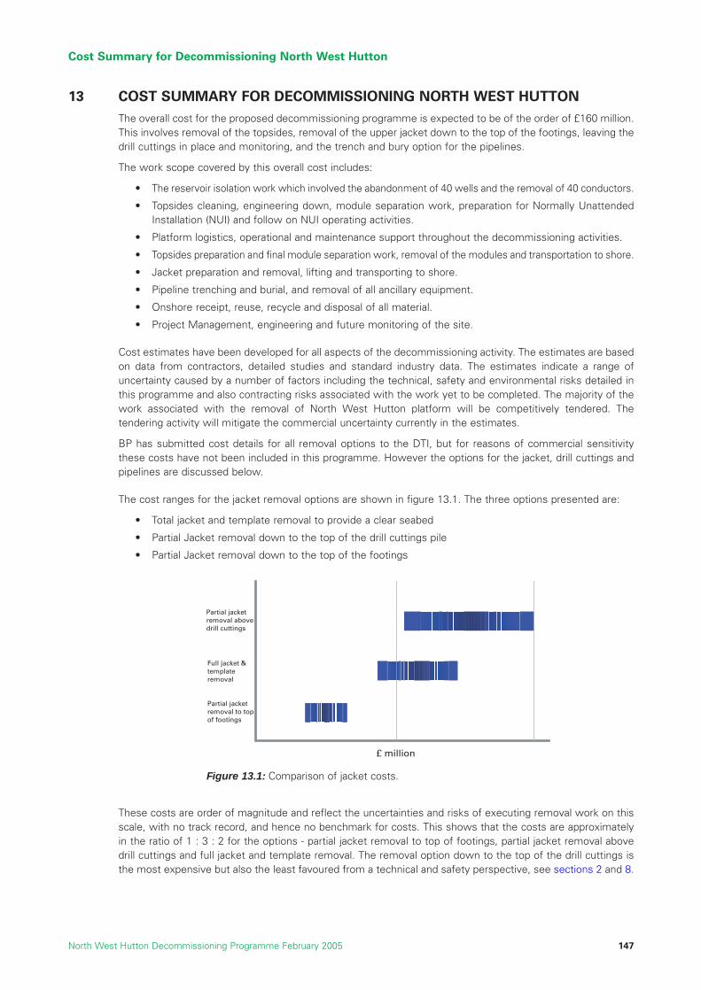
13 COST SUMMARY FOR DECOMMISSIONING NORTH WEST HUTTONThe overall cost for the proposed decommissioning programme is expected to be of the order of £160 million.This involves removal of the topsides, removal of the upper jacket down to the top of the footings, leaving thedrill cuttings in place and monitoring, and the trench and bury option for the pipelines.
The work scope covered by this overall cost includes:
• The reservoir isolation work which involved the abandonment of 40 wells and the removal of 40 conductors.
• Topsides cleaning, engineering down, module separation work, preparation for Normally UnattendedInstallation (NUI) and follow on NUI operating activities.
• Platform logistics, operational and maintenance support throughout the decommissioning activities.
• Topsides preparation and final module separation work, removal of the modules and transportation to shore.
• Jacket preparation and removal, lifting and transporting to shore.
• Pipeline trenching and burial, and removal of all ancillary equipment.
• Onshore receipt, reuse, recycle and disposal of all material.
• Project Management, engineering and future monitoring of the site.
Cost estimates have been developed for all aspects of the decommissioning activity. The estimates are basedon data from contractors, detailed studies and standard industry data. The estimates indicate a range ofuncertainty caused by a number of factors including the technical, safety and environmental risks detailed inthis programme and also contracting risks associated with the work yet to be completed. The majority of thework associated with the removal of North West Hutton platform will be competitively tendered. Thetendering activity will mitigate the commercial uncertainty currently in the estimates.
BP has submitted cost details for all removal options to the DTI, but for reasons of commercial sensitivitythese costs have not been included in this programme. However the options for the jacket, drill cuttings andpipelines are discussed below.
The cost ranges for the jacket removal options are shown in figure 13.1. The three options presented are:
• Total jacket and template removal to provide a clear seabed
• Partial Jacket removal down to the top of the drill cuttings pile
• Partial Jacket removal down to the top of the footings
These costs are order of magnitude and reflect the uncertainties and risks of executing removal work on thisscale, with no track record, and hence no benchmark for costs. This shows that the costs are approximatelyin the ratio of 1 : 3 : 2 for the options - partial jacket removal to top of footings, partial jacket removal abovedrill cuttings and full jacket and template removal. The removal option down to the top of the drill cuttings isthe most expensive but also the least favoured from a technical and safety perspective, see sections 2 and 8.
Cost Summary for Decommissioning North West Hutton
North West Hutton Decommissioning Programme February 2005 147
Partial jacketremoval to top of footings
Partial jacket removal above drill cuttings
Full jacket & template removal
£ million
Figure 13.1: Comparison of jacket costs.

The cost ranges for the drill cuttings options are given in table 2.5 and section 9.8. The ranges for the optionsare for the removal and onshore treatment £46 million to £114 million, this range narrows slightly for removaland re-injection to £43 million to £110 million; for the excavate and relocate on the seabed, or leave in-situ andcover options the costs are about £8 million to £9 million; and for the leave in-situ and monitor option the costis about £0.5 million. The wide ranges for the drill cutting removal options are a reflection of the uncertainties,risks and lack of facilities and experience for the activities required to carry out the work on the scale required.The costs are order of magnitude. For the other three options the work scope and methods are better defined,and therefore so too are the costs.
The costs for the pipeline options studied are given in table 2.6 and section 10. The costs are for recover and bringto shore about £22 million; for trench and bury about £8 million; and for leave in-situ about £5 million. These costsare reasonably well defined as the work scope and activities are known with reasonable certainty, and similar workhas been undertaken in the past. These costs include for cleaning the pipelines and future monitoring.
The costs are expressed in 2004 values, and all include allowances for engineering, project management andsupport costs. The wide ranges for some options reflects the uncertainties and risks of executing large, novelwork scopes, whereas for the smaller and better defined work scopes the costs are based on the assumptionthat the work is carried out as planned.
Cost Summary for Decommissioning North West Hutton
North West Hutton Decommissioning Programme February 2005148

14 SCHEDULE
The UK decommissioning guidelines require timely removal of redundant offshore installations unless thereare over-riding justifications for leaving them in place for a period of time. There are no identified drivers topostpone decommissioning of the North West Hutton facilities and the activity will therefore be carried out ina timely and efficient manner.
The schedule presented below provides indicative timing for the activities required to fully decommissionNorth West Hutton.
This indicative programme provides relatively wide windows for offshore activities and does not representcontinuous activity. Discussions with the contractors likely to tender for the work reveals that they valueflexibility wherever possible as this enables them to schedule work more efficiently.
This provides the opportunity for cost savings to the contractors, and for the overall project, without impartingany significant delay to achieving the overall objectives. Such flexibility also enables more efficient use ofphysical and natural resources both onshore and offshore. It is also important in helping to ensure safety inthe application of relatively untested equipment and procedures.
There is also a requirement for ongoing survey and inspection of the site. This is not shown on the schedule,but is discussed more fully in Section 18.
Schedule
North West Hutton Decommissioning Programme February 2005 149
Cessation of Production
Well Decommissioning
Clean & Make-safe
Module Separation
NUI / Removal Preparation
Pipeline Decommissioning (Window)
Platform Removal (Window)
Onshore Disposal (Window)
Debris Clearance & Final Survey
01/01/03
2003 2004 2005 2006 2007 2008 2009 2010

Schedule
North West Hutton Decommissioning Programme February 2005150

15 LICENCES ASSOCIATED WITH DECOMMISSIONING NORTH WEST HUTTON
As the decommissioning project progresses, the appropriate permits, consents and licences for all activitieswill be put in place with the relevant authorities. The responsibility for ensuring that the appropriatedocumentation is in place will rest either with the operator of the field or with the various contractors who willbe responsible for different aspects of the removal and disposal activities.
All permits, consents and licences will be managed within the overall project management structure,discussed in Section 16.
A Summary of the applicable legislation for the Decommissioning of the North West Hutton facilities can befound in Section 20.
Licences Associated With Decommissioning North West Hutton
North West Hutton Decommissioning Programme February 2005 151

Licences Associated With Decommissioning North West Hutton
North West Hutton Decommissioning Programme February 2005152

16 PROJECT MANAGEMENT
16.1 Introduction
The North West Hutton Decommissioning Project represents an important and highly significant activity forthe joint owners of the field. The project management process will require the rigorous levels of qualitycontrol, inspection and assurance that would be expected for a capital investment project of this size. BP asthe operator of the field will be responsible for the implementation of the overall project management.
BP has a well developed, company-wide approach to project management and this is being applied rigorouslyto all aspects of the North West Hutton Decommissioning project. A dedicated team “The North West HuttonDecommissioning Team” has been established to develop and implement the project from inception throughto the completion of all operations and final inspections of the site.
BP has three “business units” to manage operations in the UK sector of the North Sea. Each business unitcomprises specialist “performance units” which control a specific aspect of the overall operation. The NorthWest Hutton Decommissioning Project organisation is part of the “Developing Asset Business Unit”.
The Performance Unit and Business unit and also group-wide functions provide the control for ensuringsuccessful implementation of the project.
16.2 Health, Safety and Environment
BP recognises that HSE performance is critical to the success of the business, and is distinctive world-widein its pursuit of health, safety and environmental performance. BP’s commitment to HSE Performance is oneof the five Group Business Policies (Ethical Conduct, Employees, Relationships, HSE Performance, Controland Finance) (Ref. 16.1).
BP’s goals for HSE are simply stated as a key policy:
• no accidents
• no harm to people
• no damage to the environment
The BP HSE Management System Framework and key processes exist to support the HSE Expectations andencompass the complete spectrum of health, safety and environmental risk management including security,and the technical and operational integrity of facilities and equipment. These are the boundaries within whichthe North West Hutton Decommissioning Project will have to operate to achieve the highest possible level ofsafety and performance.
BP’s HSE Management System Framework provides a broad-based set of Expectations integrated intothirteen elements of accountability. These expectations outline BP’s requirements for the management of:
• safety and accident prevention
• plant and equipment integrity
• pollution prevention
• energy conservation
• personal, occupational and environmental health
• personal/physical security
• product stewardship
• sustainable development
Project Management
North West Hutton Decommissioning Programme February 2005 153

This framework focuses on critical HSE needs and activities, and consistently delivers improved HSEperformance. The thirteen elements of BP’s HSE Management System Framework are detailed below:
Addressing the full set of HSE Expectations is mandatory for every activity across the entire BP organisation
The studies undertaken in support of this decommissioning programme address the applicable elements ofthe HSE Management Framework at this stage in the decommissioning of North West Hutton.
As the project is defined further and moves towards the execution phase all elements will be required to beassessed to ensure the undertaking of the project with minimal risk.
16.3 Technical
The North West Hutton Decommissioning Project will be executed within the framework of the BP CapitalValue Process (CVP) and the BP HSE Management System discussed above. This sets the standards andcontrols for commercial execution and delivery of HSE excellence.
Technical delivery is core to the delivery of any project. This is managed within the CVP framework withengineering definition and construction developing in ever-greater detail through the Appraise – Select – Define- Execute – Operate phases. The major difference for North West Hutton is that this is a decommissioning, i.e.de-construction project, not a construction project for which the CVP was originally conceived. There will be no“Operation” phase, however, and the technology as such is a means to an end rather than a key deliverable;nevertheless, the same standards of technical rigour and processes will be applied.
Key control for the technical execution of the project will be established through the Project Execution Plan(PEP), Statement of Requirement (SoR) and the Assurance Plans. The PEP sets out how the project will beexecuted and establishes key controls and communications. Contracting Strategy and clarity on interfaces andresponsibilities is central to this execution.
The SoR is the prime technical document that sets out the technical requirements of the project and these include:
• Technical objectives and philosophy
• Site factors and data
• Regulatory requirements
• Design standards, with clarity on order of precedence
• Engineering deliverables to execute and control the project
• Third Party Compliance, permits and consents
The SoR develops into the basis of design and ultimately into the contractors’ detailed design briefs,documentation and procedures. A change-control process will be established by the project to ensure that thecontractors deliver the technical objectives set out in the SoR.
Decommissioning on the scale of North West Hutton is a new endeavour and brings new project challenges. Itis also a brown-field project (i.e. it involves work with existing equipment) with all the attendant difficulties anduncertainties. Assurance Plans will be essential to review and challenge the engineering and execution of theproject at all phases of the CVP. This will be done through audits and processes such as the BP value improvingpractices (VIPs), which will review critical areas of the project to ensure best practice is being achieved.
Project Management
North West Hutton Decommissioning Programme February 2005154
1. Leadership & Accountability
2. Risk Assessment
3. People, Training and Behaviours
4. Working with Contractors and Others
5. Facilities Design and Construction
6. Operations and Maintenance
7. Management of Change
8. Information and Documentation
9. Customers and Products
10. Community and Stakeholder Awareness
11. Crisis & Emergency Management
12. Incidents Analysis and Prevention
13. Assessment, Assurance and Improvement

BP will provide a quarterly written report on the progress of the decommissioning works to the DTI. This reportwill include information on the following topics:
• Health Safety and Environment.
• Highlights.
• Overall Project Status.
• Stakeholder Engagement.
• Approvals.
• Permits & Consents.
• Structures Removal.
• Waste Management.
• Concerns.
• Forthcoming Key Events.
• Costs.
16.4 Reporting
In the Define and Execute phases the DTI will be kept regularly informed of the progress of thedecommissioning work, and of any major variations, developments or HSE issues.
Within four months of completion of the works or a major component of the works, e.g. pipelines or topsideswork; a close-out report will be submitted to the DTI addressing the following topics:
• An overview of the works and the decommissioning programme as a whole.
• Confirmation that the work has been carried out in accordance with the programme.
• A description of any major variations, and any permits required for these variations.
• A description of the major milestones in the schedule and were they achieved.
• Results of debris clearance and any surveys undertaken, including any independent verification reports.
• Updated schedule, if necessary, for any future monitoring required.
• A summary of actual costs and an analysis of actual versus estimated costs and an explanation ofany variations.
References
16.1 BP HSE Policy and BP HSE Management System
Project Management
North West Hutton Decommissioning Programme February 2005 155

Project Management
North West Hutton Decommissioning Programme February 2005156

17 DEBRIS CLEARANCEIn this context, debris refers to material that is not covered in the inventories of material contained in orassociated with the platform and the pipelines.
The presence of seabed debris around the facilities in the North West Hutton field has been discussed severaltimes in the preceding sections. This debris has accumulated as a result of activities associated directly withthe operation of the field. It also includes material from other activities which may have been inadvertentlydragged or introduced into the area. Debris clearance will take place during the removal activities themselvesand also as part of the final assurance activities on completion of operations.
Sections 7-10 describe the decommissioning outcomes proposed for the topsides, jacket, drill cuttings andpipelines. All material associated with these items will be handled in the manner described. During the operationsto carry out the recommended programme, it is likely that sub-sea activities, particularly those close to theseabed (e.g. pipeline activities), will encounter items of debris. All items of debris identified will be assessed andrecovered or managed in the most appropriate manner to ensure that the seabed is left in the condition proposedby this decommissioning programme. These over trawl sweeps will be carried out by the fisherman.
The area covered by the debris survey will be the area within the 500 metre zone around the platform and thecorridor of the pipelines out to 100 metres either side of each pipeline. The initial debris survey will be bymeans of a ROV, with items being removed by means of an ROV or by other methods as required.
Following completion of decommissioning activities on North West Hutton, a final programme of clearancewill be implemented to ensure that the recommended outcome has been achieved. The methodology forachieving this assurance will involve several sweeps of the site by trawlers using specially adapted equipment.The sweeps will be implemented in several directions around the site of the platform and also along the routeof the two pipelines included in this programme.
The sweeps will ensure that there are no seabed obstructions in the vicinity of the various work sites. Ifobstructions are encountered, the nature of the obstruction will be identified and, if necessary, a separateintervention will be made to remove the obstruction. Information from surveys around North West Hutton andsimilar activities elsewhere indicates that these assurance sweeps will collect, and enable the removal of,smaller items of debris not identified by other activities.
The results of seabed surveys, trawler sweeps and debris removal will be collated into a report and submittedto the DTI’s Offshore Decommissioning Unit. This report will form the basis of any on-going surveys andmonitoring for the platform site and the pipeline routes.
Debris Clearance
North West Hutton Decommissioning Programme February 2005 157

Debris Clearance
North West Hutton Decommissioning Programme February 2005158

18 PRE- AND POST- DECOMMISSIONING MONITORING AND MAINTENANCE
18.1 Pre-Decommissioning Monitoring
The North West Hutton owners have ensured that the site of the platform, pipelines and the surrounding areahave been subject to comprehensive monitoring and survey work to understand the impact of ongoingoperations. This information will provide the baseline for all future monitoring activity and evaluation.
18.2 Post Decommissioning Monitoring
Within a year of the completion of the decommissioning activity and debris clearance recommended by thisprogramme, the site will be subjected to a physical and environmental survey to establish a post-decommissioning baseline for the site.
The scope of the post-decommissioning survey will be agreed with the DTI before the work is carried outand the survey results submitted to the DTI. The environmental survey is likely to be based upon thetransects and stations sampled in the 20002 survey (see table 3.2 in Section 3) to allow temporalrecovery trends to be evaluated. Samples will be analysed for hydrocarbons, metals and other tracecontaminants. The morphology of the drill cuttings pile my also be evaluated if it is believed to have beendisturbed during decommissioning activities.
In light of the results of the post decommissioning survey findings and all previously available surveyinformation the field owners in conjunction with the DTI, will determine the scope and frequency for futuresurveys to monitor the condition of the site, the structure and all other material left in-situ, to ensure theyremain as expected as a result of this decommissioning programme. The results of all surveys will besubmitted to the DTI.
The field owners are aware that all items left in-situ as part of this decommissioning programme remain theirproperty and that they have a continuing liability for these items. The field owners are committed to ensuringthat future obligations arising from the implementation of this decommissioning programme are met.
Pre- and Post- Decommissioning Monitoring and Maintenance
North West Hutton Decommissioning Programme February 2005 159

Pre- and Post- Decommissioning Monitoring and Maintenance
North West Hutton Decommissioning Programme February 2005160

19 ENVIRONMENTAL STATEMENT SUMMARY
19.1 Introduction
As described in Section 6.4.2, as part of the comparative assessment study work undertaken to support thedecommissioning programme for North West Hutton, an Environmental Impact Assessment (EIA) has beenundertaken. The results of the EIA are presented in the North West Hutton Environmental Statement (Ref. 19.1).
This section of the decommissioning programme presents a brief summary of the Environmental Statement, butfocuses on a description of the methodology used in the Environmental Risk Analysis (ERA) process, the resultsobtained for each of the potential outcomes and a discussion of which outcome offers the lowest environmentalrisk. A summary of the environmental description of the North West Hutton location is given in Section 3.
The complete Environmental Statement includes:
• a description of the environmental setting at North West Hutton.
• a description of the method used to assess the environmental effects of operations and outcomes(the ERA).
• the results of the ERA that could arise as a result of planned and accidental events arising duringthe operations.
• an indication of the mitigating measures that would be adopted to reduce or eliminate potential effects,including monitoring.
• calculations of the energy that would be used, and the total emissions of gases that would arise, as aresult of completing any of the outcomes.
• an analysis of the relative environmental advantages and disadvantages of the outcomes for each facility,with a recommendation of the outcome that, overall, may provide the least environmental effect.
19.2 Method Used to Assess and Compare Environmental Risks
A four stage process (an Environmental Risk Assessment [ERA]) was used to assess environmental risks andcompare the different outcomes for facilities.
The method used to undertake the ERA is one that has been widely applied internationally in the explorationand production industry, and in other industrial sectors. The methodology has been adapted from the approachto risk assessment and rating given in the British Standard BS 8800:1996 (Ref. 19.2), the DTI Guidelines forEnvironmental Statements (Ref. 19.3), the methods used in numerous statutory ESs for UK offshore oil andgas projects (which are legally required to demonstrate a risk-based approach), and the methods usedspecifically by BP during the preparation of ESs for the Magnus Enhanced Oil Recovery Project (Ref. 19.4) andthe Clair Phase 1 Development (Ref. 19.5). These ESs have been subject to rigorous review during thestatutory consultation and approval process.
(1) Each potential programme and outcome for each facility was reviewed, and the events and operationsthat would or could give rise to environmental effects in any environmental compartment were identified.
(2) Each effect was assigned to an environmental risk category (Table 3) on the basis of the probability ofthe impact occurring and the severity of the consequences if it occurred. Pre-defined probability (Table1) and consequence criteria were used to evaluate the environmental risk (Table 2). The environmentaleffects were assessed on the assumption that the mitigation measures (measures to reduce thelikelihood or consequence of a risk, or eliminate it) proposed by or stated in the project programme,would be in place.
Environmental Statement Summary
North West Hutton Decommissioning Programme February 2005 161
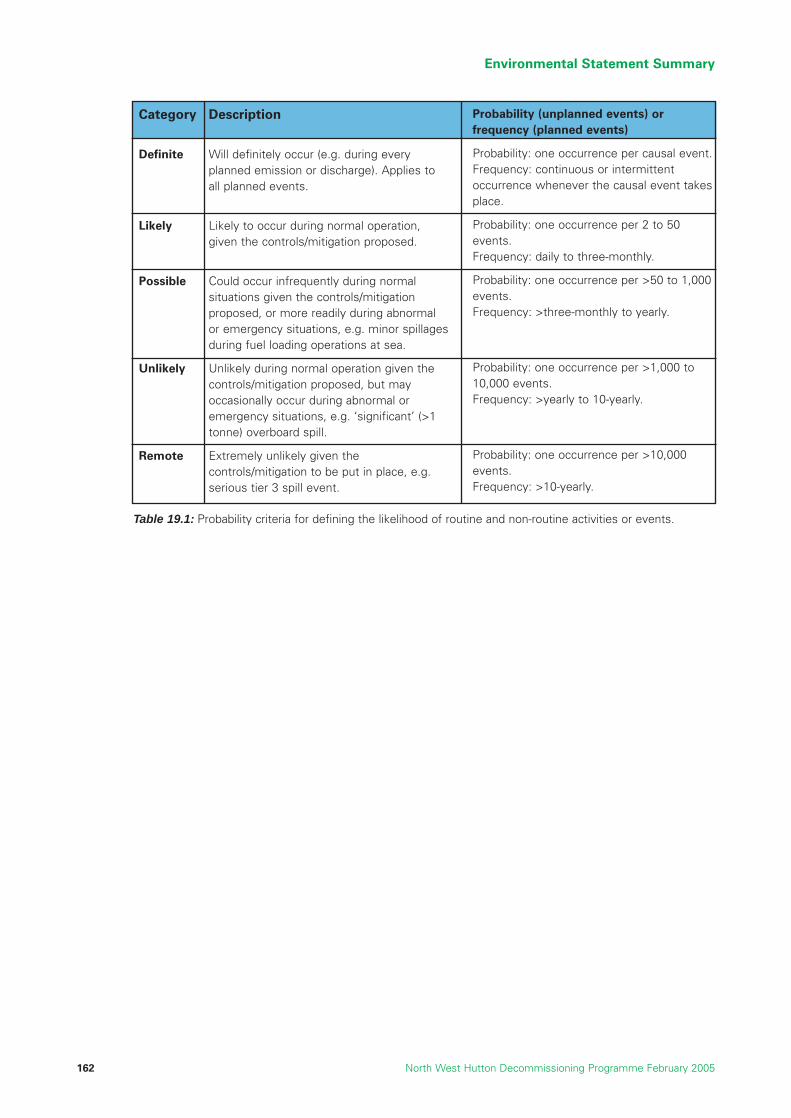
Environmental Statement Summary
North West Hutton Decommissioning Programme February 2005162
Category
Definite
Likely
Possible
Unlikely
Remote
Description
Will definitely occur (e.g. during everyplanned emission or discharge). Applies toall planned events.
Likely to occur during normal operation,given the controls/mitigation proposed.
Could occur infrequently during normalsituations given the controls/mitigationproposed, or more readily during abnormalor emergency situations, e.g. minor spillagesduring fuel loading operations at sea.
Unlikely during normal operation given thecontrols/mitigation proposed, but mayoccasionally occur during abnormal oremergency situations, e.g. ‘significant’ (>1tonne) overboard spill.
Extremely unlikely given thecontrols/mitigation to be put in place, e.g.serious tier 3 spill event.
Probability (unplanned events) orfrequency (planned events)
Probability: one occurrence per causal event.Frequency: continuous or intermittentoccurrence whenever the causal event takesplace.
Probability: one occurrence per 2 to 50events.Frequency: daily to three-monthly.
Probability: one occurrence per >50 to 1,000events.Frequency: >three-monthly to yearly.
Probability: one occurrence per >1,000 to10,000 events.Frequency: >yearly to 10-yearly.
Probability: one occurrence per >10,000events.Frequency: >10-yearly.
Table 19.1: Probability criteria for defining the likelihood of routine and non-routine activities or events.

Environmental Statement Summary
North West Hutton Decommissioning Programme February 2005 163
• Degradation or loss of habitats or ecologically,commercially or culturally important species.
• Extent: At a regional, national or international scale.
• Duration: Low prospects of recovery to arepresentative state, within several decades inhighly affected areas.
• Atmospheric emissions at levels equivalent to or abovethe annual GHG or VOC tonnages for the UKCS oil andgas industry. This approximates to 5-100% of the totalannual CO2-E emissions from all UK households.
• Permanent, widespread impacts on resource qualityand availability (i.e. of water, energy or raw material) tothe long-term detriment of dependent businesses,communities, individuals, environment and socio-economic conditions.
• Permanent impact on status of internationally importantor nationally protected sites or species, e.g. coastalregions of Shetland.
• Tier 3 spill or catastrophic emergency event, withconsequences on a national or international scale.
• Well-established and widely held areas of concern insociety on a national or international scale, includingpossible perception of threats to the globalenvironment, e.g. global warming, and wider issues ofsustainability.
• Permanent, detrimental health impacts (any number ofpeople)
• Permanent and widespread negative effects on humanwell- being (typically, but not necessarily, arising fromnuisance).
• Permanent disruption to business, communities orindividuals, with permanent consequential loss ofrevenue, assets or amenities.
• Requirement to dispose of controlled waste beyondnational disposal capacity.
• Degradation or loss of habitats or ecologically,commercially or culturally important species over awide area of seabed.
• Extent: Generally more than 1,000m from thesource of the impact, or beyond the perimeterboundaries of onshore sites.
• Duration: Limited prospect of recovery to normalhealthy conditions. Recovery to a representativestate would generally be in the order of decades inhighly affected areas.
• Atmospheric emissions at levels equivalent to or abovethe annual GHG or VOC tonnages for BP in the UKCS.This approximates to 1-5% of the total annual CO2-E
emissions from all UK households.
• Substantial but ultimately reversible impacts onresource quality and availability (i.e. of water, energy, orraw material) to the detriment of dependentbusinesses, communities, individuals, environment andsocio-economic conditions.
• Serious, long-term, but ultimately reversible, impactwhich would affect the status and/or management ofinternationally important or nationally protected sites orspecies e.g. coastal regions of Shetland.
• Tier 2 or 3 oil spill or major emergency event, withconsequences on a local or regional scale.
• Concern on a regional rather than local or global levelinvolving multiple interest groups. Perception of threatto the regional environment and issues of regionalsustainability.
• Reversible, detrimental health impacts (any number ofpeople).
• Widespread and sustained negative effects on humanwell- being (typically on a scale of months to years;also typically, but not necessarily, arising fromnuisance).
• Long term (typically on a scale of months to years)disruption to businesses, communities or individuals,with sustained consequential loss of revenue, assets oramenities.
• Requirements to dispose of controlled waste beyond50% of the annual disposal capacity of the wastemanagement region (e.g. county or regional level).
SEVERE
Environmental Consequences Social Consequences
MAJOR
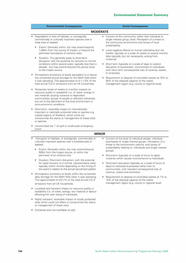
Environmental Statement Summary
North West Hutton Decommissioning Programme February 2005164
• Degradation or loss of habitats, or ecologically,commercially or culturally important species over awide area of seabed.
• Extent: Generally within, but may extend beyond,1,000m from the source of impact, or beyond theperimeter boundaries of onshore sites.
• Duration: This generally leads to short-termdisruption with the potential for recovery to normalconditions within several years -typically less than adecade - but may extend beyond this period closeto the impact source.
• Atmospheric emissions at levels equivalent to or abovethe consented annual tonnage for the NWH field whenit was operating. This approximates to 0.1-1.0% of thetotal annual CO2-E emissions from all UK households.
• Temporary (scale of weeks to months) impacts onresource quality or availability (i.e. of water, energy orraw material) causing nuisance to dependentcommunities, groups of people or affected individuals,but not to the detriment of the local environment orsocio-economic conditions.
• Short-term, reversible impact on internationallyimportant or nationally protected sites or species e.g.coastal regions of Shetland, which could notcompromise the status or management of these sitesor species.
• Uncontrolled tier 1 oil spill or small-scale emergencyevent.
• Concern at the community, rather than individual orsingle interest group, level. Perception of a threat tothe community environment and issues of localsustainability.
• Local negative effects on human well-being (but nothealth), typically on a scale of weeks to several months(also typically, but not necessarily, arising fromnuisance).
• Short term (typically on a scale of days to weeks)disruption to businesses, communities or individuals,with short term consequential loss of revenue, assetsor amenities.
• Requirement to dispose of controlled wastes at 10% to50% of the disposal capacity of the wastemanagement region (e.g. county or regional level).
• Disruption to habitats, or ecologically, commercially orculturally important species over a localised area ofseabed.
• Extent: Generally within, but may extend beyond,500m from the impact source, or within theperimeter of an onshore site.
• Duration: Short-term disruption, with the potentialfor rapid recovery to a normal, representative statetypically within months depending on the timing ofthe event in relation to the annual recruitment pattern.
• Atmospheric emissions at levels within the consenteddaily tonnage for the NWH field when it was operating.This approximates to 0-0.1% of the total annual CO2-E
emissions from all UK households.
• Localised and transient impact on resource quality oravailability (i.e. of water, energy, raw material or labour)affecting the well- being of individuals.
• Highly transient, reversible impact on locally protectedsites which could not affect or compromise the statusor management of these sites.
• Contained and non-notifiable oil spill.
• Concern at the level of individual people, individualbusinesses or single interest groups. Perception of athreat to the environment used by, and issues ofsustainability relating to, individuals and single interestgroups.
• Short-term (typically on a scale of hours to days)nuisance which causes inconvenience to individuals.
• Short-term disruption (typically on a scale of hours todays) to individual businesses rather than tocommunities, with transient consequential loss ofrevenue, assets and amenities.
• Requirement to dispose of controlled wastes at 1% to10% of the disposal capacity of the wastemanagement region (e.g. county or regional level).
MODERATE
Environmental Consequences Social Consequences
MINOR

Environmental Statement Summary
North West Hutton Decommissioning Programme February 2005 165
• Transient disruption to habitats, or ecologically,commercially or culturally important species.
• Extent: Within 500m of the source of the impact
• Duration: Potential for recovery to a normal,representative state, generally within hours to days.
• Atmospheric emissions from transient and/or smallscale sources (e.g. exhausts from small items of plantor equipment).
• Negligibly small impacts on resource availability orquality which is not to the detriment of people, theenvironment, or socio-economic conditions.
• No impact on status of protected sites or species.
• No spills or emergency events.
• No concern or perception of threats by people,communities or interest groups.
• Transient nuisance (scale of hours) which does notcause negative effects on human health, well-being,revenue sources, assets or amenities or socialdisruption.
• Requirement to dispose of controlled wastes at lessthan 1% of the disposal capacity of the wastemanagement region (e.g. county or regional level).
NEGLIGIBLE
Environmental Consequences Social Consequences
• Enhancement of habitats, or ecologically, commerciallyor culturally important species.
• Enhancement of human prosperity, health, well-beingor amenities.
• No requirement to dispose of controlled waste to land-fill.
POSITIVE
Table 19.2: Consequence criteria for defining the characteristics of environmental effects.

Key:
(3) The four risk categories were:
(4) Assigning the negative risks to one of three categories allowed a wide range of potential risks to bescreened, so that attention could be focussed on important risks – in the categories “highly significant”and “significant” - that could be influential in the selection of an outcome for those facilities wheremore than one outcome was available. Risks in these categories were then subjected to more detailedassessment in order to provide information about the absolute level of impact that might beexperienced should the risk be realised.
Environmental Statement Summary
North West Hutton Decommissioning Programme February 2005166
Severe
Major
Moderate
Minor
Negligible
Positive
R.6
R.5
R.4
R.3
R.2
R.1
U.6
U.5
U.4
U.3
U.2
U.1
P.6
P.5
P.4
P.3
P.2
P.1
L.6
L.5
L.4
L.3
L.2
L.1
L.6
L.5
L.4
L.3
L.2
L.1
ConsequenceProbability
Remote Unlikely Possible Likely Definite
HighlySignificant
Zone
SignificantZone
Not SignificantZone
PositiveZone
Highly significant
Significant
Not significant
Positive
An unacceptable level of risk that should beeliminated or reduced to an acceptable level bydeveloping specific control or mitigation measures.
A tolerable risk that is considered “As Low AsReasonably Practical” (ALARP). There is scope forfurther reducing the effect by control or mitigationmeasures.
A risk with a trivial effect that could be managed bystandard control and mitigation measures.
Any type of risk that would result in a positive orbeneficial effect in the environment.
Table 19.3: Matrix showing how the criteria of probability and consequenceare combined to generate an overall risk rating.

Different outcomes for any facility were compared by a combination of quantitative and qualitativeexaminations of their performance. The numbers of positive, “highly significant” and “significant” risks ineach outcome were compared, but this analysis was tempered by a consideration of the qualitative nature ofthe risks being examined. The amount of the facility removed to shore was expressed as a percentageremoved (%) in relation to the total mass of material presently at the site.
The relative use of energy and the gaseous emissions in each outcome were also compared, bearing in mindthat prediction of energy use and gaseous emissions in decommissioning activities may be subject toconfidence limits of +/- 20-30%. Energy was expressed in gigajoules (GJ) and in terms of the average energyuse of UK households; in 2001 the average annual consumption of energy by each UK household was about80GJ, and energy requirements were expressed in UK household equivalents as well as absolute amounts.Gaseous emissions were expressed in terms of tonnes of carbon dioxide equivalents (CO2-E) which indicatesthe greenhouse gas potential of all the gases emitted. In 2000, the average annual CO2-E emissions for eachUK household was about 6 tonnes CO2-E.
19.3 Decommissioning the Topsides
19.3.1 Outcome: Decommissioning the Topsides by Total Removal
In accordance with legislation, the topsides will be completely removed and returned to shore for recycling anddisposal. All the modules and associated equipment will be removed by a heavy lift vessel (a large floating cranecapable of lifting about 7,000 tonnes), in a programme that is the reverse of the original installation process.
Onshore, the modules will be progressively dismantled in a managed programme that will identify thedifferent materials on and in the structures, and ensure that they are handled, stored, treated and disposed ofsafely. Careful attention will be paid onshore to separating the different types of material from the topsides.Specialist contractors and disposal firms will deal with any residues of hazardous waste that remain in pipework or equipment. The structural components will be dismantled by mechanical cutting techniques so thatthe pieces can be transported to recycling or disposal sites. The project would aim to recycle at least 97% ofthe topsides structure by weight.
19.3.2 Environmental Risks: Decommissioning the Topsides by Total Removal
The ERA identified 13 “significant” risks associated with this outcome. The majority of these risks would have“minor” consequences for the environment, as a result of cutting and lifting operations, and the activities ofvessels. Most impacts would be very localised and short-lived, and similar to those that may be caused by avariety of normal offshore activities. There would be no planned discharges of oil or chemicals to sea otherthan those from the normal operations of vessels.
Only the remote possibility of an accidental spill of oil following a vessel collision would result in a “significant”risk with a “major” consequence. This remote event is common to all activities requiring the use of vesselsoffshore, and while the risk is not ignored, it is omitted from the following analyses and comparison ofoutcomes for the North West Hutton facilities.
All material would be treated or disposed of by licensed contractors at licensed sites. BP’s Duty of Careextends beyond the quayside and we would work with onshore licensed disposal sites to undertake alldismantling activities in a responsible manner. The environmental impacts that would be experienced atany onshore site selected for receiving and dealing with material from North West Hutton would be short-lived, localised and managed, and similar to those that have previously arisen during past commercialactivities at the site.
Environmental Statement Summary
North West Hutton Decommissioning Programme February 2005 167
Number of risks in each category Energy EmissionsOUTCOMEPositive Significant Highly
significant
% remove GJ Household
equivalentsCO2-E Household
equivalentsRemove completely and recycle
4 13 0 100 600,000 7,500 44,000 6,900
Table 19.4: Summary of environmental assessment for decommissioning the topsides.

19.4 Decommissioning the Jacket
19.4.1 Outcome: Decommissioning the Jacket by Total Removal
The impacts offshore and onshore arising from the decommissioning of the jacket would be very similar tothose that would arise from decommissioning the topsides, and would be localised and temporary. The jacketwould be cut underwater into 8-10 main sections, lifted by a heavy lift crane and taken to shore for recycling.Cutting would be achieved by a combination of abrasive water jet cutting and diamond wire cutting. The jacketlegs and bracings do not contain any oil or chemicals, and the bulk of material that would be handled is steeland sacrificial anodes made of aluminium alloy. It is possible that the jacket would be taken to the sameonshore site as the topsides for dismantling and recycling.
19.4.2 Environmental Risks: Decommissioning the Jacket by Total Removal
The impacts offshore and onshore arising from the decommissioning of the jacket would be very similar tothose that would arise from decommissioning the topsides. The ERA identified 14 “significant” risksassociated with this outcome. The majority would have “minor” consequences for the marine environmentand are associated with the cutting and lifting operations, and the activities of vessels. Most impacts wouldbe very localised and short-lived, and similar to those that may be caused by a variety of normal offshoreactivities. Planned activities associated with the removal of the jacket would not result in significantenvironmental impacts, but it is possible that if part of the jacket were to fall onto the drill cuttings pile, thisdisturbance of cuttings could result in a local, short-lived impact to the benthos and water column. It is likelythat impacts to the benthos would be confined to the area of seabed presently affected by the presence andeffects of the cuttings pile. There would be no planned discharges of oil or chemicals to sea other than thosefrom the normal operations of vessels.
19.5 Decommissioning the Footings
Three decommissioning outcomes were considered for the footings; total removal, partial removal, and leavein-situ and monitor.
19.5.1 Total Removal of the Footings
19.5.1.1 Outcome: Decommissioning the Footings by Total Removal
Cutting techniques such as abrasive cutting and diamond wire cutting would be used to cut the bracings,bottlelegs and piles. The footings would be dismantled into 30-40 which included the damaged seabedmembers sections and lifted to the surface by heavy lift vessel, for return to shore and recycling. The removalof the template lying on the seabed would require the use of explosives underwater and individual chargeswould probably be of about 5-7kg.
The majority of the existing volume of cuttings would have to be removed to permit access to the footings sothat they could be totally removed and returned to shore for recycling.
19.5.1.2 Environmental Risks: Decommissioning the Footings by Total Removal
The potential environmental risks of the necessary activity to remove the cuttings pile to allow removal of thefootings would be similar to those described for the total removal of the cuttings pile (Section 19.6). The suctiondredger option is the scenario adopted for the purposes of comparing outcomes. Furthermore, for the purposesof the EIA the assumed method of disposal is by re-injection to new wells on-site, since this route offers asmaller number of impacts than others (Section 19.6) and thus does not prejudice the evaluation of the outcometo remove the footings totally by assigning it the worst-case cuttings disposal risk.
Environmental Statement Summary
North West Hutton Decommissioning Programme February 2005168
Number of risks in each category Energy Emissions OUTCOME Positive Significant Highly
significant
% remove GJ Household
equivalents CO2-E Household
equivalents Remove completely and recycle
5 14 0 100 261,000 3,300 21,000 3,200
Table 19.5: Summary of environmental assessment for decommissioning the jacket.

On the basis of these assumptions, the ERA identified 33 “significant” risks associated with this outcome, ofwhich 14 relate to the recovery and disposal of cuttings and 19 to the removal and disposal of the footings.This outcome does not exhibit any “significant” risks which would have a “major” consequence for theenvironment. Some events would have a “moderate” consequence and these include; the re-suspension ofcuttings during recovery; the accidental spillage of cuttings during recovery or transportation and off-loading,and the effects of using underwater explosives to remove the template (the only technique available toremove the template). These events would cause impacts in the water column, and to the seabed and itsassociated benthic communities.
Underwater explosions cause pressure waves and loud noises that can be damaging or fatal to marinemammals, fish and plankton. The severity of any such impact depends on the size and type of charge usedand the proximity of individuals when it is detonated. There are no particularly significant areas for juvenilefish or shellfish in the area, although the platform is located within the large areas used for the spawningof several species. Marine mammals exhibit a variety of responses to underwater noise, and there is someinformation with which to judge the potential effects of noises of different frequencies and intensities.Harbour porpoises, minke whales and Atlantic white-sided dolphins are all known to be present onoccasion, in the North West Hutton area.
This outcome would result in 2 positive impacts, namely the removal of an obstruction from the seabed, andthe exposure of a small area of seabed and benthos.
19.5.2 Partial Removal of the Footings
19.5.2.1 Outcome: Decommissioning the Footings by Partial Removal
The large-diameter bottlelegs and the bracings would be severed by diamond wire cutting and abrasive waterjet cutting, so that the footings were cut down to about 3-6m above the present profile of the cuttings pile.The remainder of the footings would be left buried in the cuttings pile. Cuttings would not have to be removedto complete these cuts but there may be some minor disturbance of the cuttings. All material recovered fromthe seabed would be returned to shore for recycling or disposal.
19.5.2.2 Environmental Risks: Decommissioning the Footings by Partial Removal
The ERA identified 15 “significant” risks in this outcome, the most serious of which had a consequence ratedas “minor”.
There is a risk that sections of footings could be accidentally dropped during lifting, and this could result in thedisturbance of the cuttings pile. It is likely that impacts to the benthos would be confined to the area of seabedpresently affected by the presence and effects of the cuttings pile.
Those parts of the footings left on the seabed (and partially buried in the cuttings pile) would corrode over along period of time. This would have essentially no impact on the water column or benthos, because corrosionproducts are inert and not toxic. The most significant effect of leaving parts of the footings on the seabedwould be small but long-term effect on commercial fishing operations. Fishing would be limited over the areaoccupied by the remains of the footings because of the seabed snagging risk they would represent, althoughmid-water trawling could be carried out in the water column above the footings. Any obstruction will be clearlymarked on navigation charts and additional mitigation measures would be reviewed.
19.5.3 Leave the Footings in-situ and Monitor
19.5.3.1 Outcome: Decommissioning the Footings by Leaving in-situ and Monitoring
The whole of the footings (about 40m high and weighing about 9,500 tonnes) would be left on the seabed. Overtime the steel structure would corrode, and eventually collapse onto the seabed. The corrosion products wouldbe largely inert and not bio-available, and would not impact the local benthic or “pelagic” (water column)communities. Monitoring of the footings would be required for an unspecified period of time.
Environmental Statement Summary
North West Hutton Decommissioning Programme February 2005 169

19.5.3.2 Environmental Risks: Decommissioning the Footings by Leaving in-situ and Monitoring
If the footings were left in-situ, impacts could arise as a result of their long-term presence, and ultimatedeterioration and collapse. In addition, monitoring activities would use fuel, and give rise to gaseousemissions, but both sources of impact would be trivial in the context of general commercial activity in theNorth Sea and compared to the fuel requirements for complete removal of the footings.
The ERA identified 1 “significant” risk associated with this outcome. The footings would represent a potentialsnagging point for bottom-towed fishing gear, and it was concluded that the long-term presence of the footingswould have a socio-economic effect on the fishing industry. However, given the relative economic value of theNorth West Hutton area for fishing, and the small area of seabed that would not be available for fishing, theoverall socio-economic impact of leaving the footings in-situ is expected to be “minor”.
19.5.4 Comparison of Outcomes for the Footings
The performance of the three potential outcomes for the footings is shown in Table 19.6. To enable the fullestpossible comparison, a variation of the outcome “complete removal” is also given (1b) which excludes all ofthe risks that would be incurred in partially removing the cuttings pile to allow this outcome to be undertaken.
Notes:1a. This outcome includes all the risks that would necessarily be incurred in removing of the cuttings, and has been
debited with the energy and emissions estimated necessary for removing this volume of the cuttings pile andreinjecting on-site.
1b. This outcome excludes any risks associated with removing the cuttings.
The positive risks in the outcomes “2. Partial removal” and “3. Leave in-situ” are associated with minor inputsof organic material (nutrients) from vessels, and the small “reef effect” that might be created by the continuedpresence of part of the footings, and may all be regarded as trivial. Complete removal would eliminate anobstruction from the seabed, and also re-expose a small part of the seabed which would subsequently berecolonised by benthic species.
None of the outcomes exhibits any negative risks that would be “highly significant”; all of the risks were either“significant” or “not significant”.
The outcome “3. Leave in-situ” has 1 positive and 1 “significant risk”. This risk relates to the socio-economiceffect to fishermen of the long-term presence of a feature on the seabed. Given that there would be a long-term monitoring programme should the footings be left in place, and that measures would be available bothfor fishermen to avoid the footings obstruction and continue fishing activities at other sites, it is believed thatthis risk can be managed effectively. The outcome “3. Leave in-situ” has the lowest energy use of thetechnically feasible outcomes considered. The outcome “1b. Complete removal without any requirement tomove the cuttings pile”, included for comparative purposes, might use less energy, but the difference(38,000GJ, 15%) is probably not significant given the assumptions that have to be made regarding theestimation of energy use in decommissioning outcomes.
Environmental Statement Summary
North West Hutton Decommissioning Programme February 2005170
Number of risks in each category Energy Emissions OUTCOME Positive Significant Highly
significant
% remove GJ Household
equivalents CO2-E Household
equivalents 1a. Complete removal and recycle
12 33 0 100 535,000 6,700 41,000 6,500
1b. Complete removal and recycle
6 19 0 100 260,000 3,300 21,000 3,200
2. Partial removal
5 15 0 75 307,000 4,000 23,000 3,600
3. Leave in situ
1 1 0 0 298,000 3,800 17,000 2,700
Table 19.6: Summary of environmental assessment for decommissioning the footings.

The outcome “2. Partial removal of the footings” incurs many more “positive” and “significant” impacts thanoutcome “3. Leave in-situ”, but does not eliminate the single socio-economic risk that the footings wouldrepresent to the fishing industry. It would use about 3% more energy than outcome “3. Leave in-situ”, butthis difference is probably not significant given the method used. This outcome would, however, give rise toabout 35% more CO2-E emissions than the outcome “3. Leave in-situ”, principally because of combustion offuel by vessels. The outcome “2. Partial removal” would also use more energy (47,000GJ, about 18%) thanthe comparative outcome “1b. Complete removal without any requirement to move the cuttings pile”,because it would use energy for both offshore removal operations and for replacing material not returned forrecycling onshore. If the drill cuttings were to be covered, depending on the height of the stumps of the bottlelegs above the pile, these would be partially covered by the thickness of the cover material itself. Tocompletely cover the stumps and to offer some protection against erosion of the pile, it is likely that thethickness of the cover would have to be significantly increased from that proposed to cover the pile alone. Thiswould in turn increase the area of seabed covered, the quantity of material required to construct the cover andthe volume of the covered pile.
The outcome “1a. Complete removal after removal of the cuttings pile” has twice the number of “positive”impacts exhibited by “2. Partial removal”. Only 4 of these are significant, however, relating to the removal ofobstructions from the seabed and the exposure of a small area of the benthos. The other positive impacts aretrivial and result from the input of organic material from vessels offshore. The outcome “1a. Complete removalafter removal of the cuttings” also has twice the number of “significant” impacts in comparison with theoutcome “2. Partial removal”, as a result of the multiple effects of both removing the cuttings pile and thenremoving the footings. In addition, this outcome would use about 74% more energy than the nearest outcome“2. Partial removal”. This difference is significant given the assumptions that have to be made regarding theestimation of energy use in decommissioning outcomes.
From our assessment of the environmental risks, the outcome for the footings that offers the leastenvironmental impact would be “3. Leave in-situ”. There is no over-riding environmental imperative for theirremoval, and operations to remove them completely would incur associated environmental risks as a result ofthe need to remove at least 90% of the cuttings pile.
If the footings were required to be removed, the most environmentally preferable method to remove thecuttings would be by using the suction dredger tool.
19.6 Decommissioning the Drill Cuttings Pile
There are six outcomes for decommissioning the cuttings pile. The range of offshore activities, and theextent to which the pile may be disturbed or removed, varies considerably from outcome to outcome.Consequently, there are significant differences in the type, number and severity of the environmental risksthat would arise either as a result of carrying out the operations to deal with the pile, or from the resultantlong-term condition of the pile.
19.6.1 Leave in-situ and Monitor
19.6.1.1 Outcome: Decommissioning the Cuttings Pile by Leaving in-situ and Monitoring
No remedial work would be carried out on the pile which would be left uncovered at its present location. Itscondition and effects on the immediate environment would be monitored by means of an approved long-termprogramme. This outcome could only apply if the footings were also left in-situ.
19.6.1.2 Environmental Risks of Decommissioning the Cuttings Pile by Leaving in-situ and Monitoring
The ERA identified 16 “significant” risks associated with this outcome, the most serious of which would havea “moderate” consequence.
If the cuttings pile were left in-situ it is estimated that it will persist for one to five thousand years (although itis recognised that uncertainties in the model used to predict its persistence may result in a larger duration).During this time the hydrocarbons in the pile would degrade (break down) only slowly. Currents, wave actionand bioturbation (the physical mixing of the material by animals living on the seabed) may disturb the SAL fromtime to time, and this may result in the release of small amounts of oil into the water column. This would bedispersed and diluted by currents, and would not cause surface slicks at the site.
Environmental Statement Summary
North West Hutton Decommissioning Programme February 2005 171

Cuttings, oil-based muds and other contaminants in the pile have caused measurable impacts on the surfaceof the seabed around North West Hutton and this has been carefully monitored. Since the discharge ofcuttings ceased in 1992, the zone of seabed surface impact around the periphery of the cuttings pile hasdecreased. At present the pile is causing only a minimal impact in the adjacent water column and surroundingbenthos. The seabed around the pile would slowly recover from the impacts of oily cuttings, and the area ofseabed exhibiting elevated concentrations of hydrocarbons and metals, and perturbed benthic communities(affected by physical or chemical factors and therefore not completely similar to areas of “natural” seabed),would continue to decrease. Fish may be exposed to increased concentrations of hydrocarbons, but there isno evidence to suggest that fish caught in the vicinity of piles such as that at North West Hutton exhibitconcentrations that are significantly higher than those of fish taken from areas away from platforms. Noexamples of tainted fish (fish having a smell or taste that is noticeably different to the “normal” smell or tasteof that species) have been found around cuttings piles.
It is possible that the periphery of the pile could be disturbed by bottom-towed fishing gear. This would leadto the re-suspension of cuttings into the water column and their subsequent resettlement on the seabed.Such incidents would cause local and short-lived impacts on the water column. They could also lead to aspreading and thinning of the pile, with a consequent increase in biodegradation rates, as well as possiblecontamination of clean seabed. However, if the pile is left in-situ, disturbance by bottom-towed fishing gearis not likely to be frequent.
19.6.2 Leave in-situ, Covered
19.6.2.1 Outcome: Decommissioning the Cuttings Pile by leaving in-situ Covered
After removal of the jacket, the cuttings pile would be covered by 90,000 m3 of sand, gravel and rock whichwould be placed in layers. This would help to reduce the rate at which contaminants leach from the pile andalso help to protect the extremities of the pile from physical disruption by bottom-towed fishing gear. Thecondition of the pile and its effects on the immediate environment would be monitored by means of a long-term programme agreed with the authorities.
19.6.2.2 Environmental Risks of Decommissioning the Cuttings Pile by Leaving in-situ Covered
The ERA identified 18 “significant” risks associated with this outcome, the most serious of which have“moderate” consequences.
The covering operation might result in the re-suspension of small amounts of cuttings and oil into the watercolumn, and the subsequent resettlement of cuttings onto the seabed, although covering operations wouldbe carried out in such a way as to minimise this effect. It is possible that some clean areas of seabed couldbe impacted by the resettlement of oily cuttings, and that chemical and biological perturbation resulting fromthe presence of the cuttings pile could be increased. Such an increase might be detectable for a small numberof years after completion of the covering operations, but the area affected would decrease slowly asbiodegradation processes took effect.
Little information is available about the degree to which contaminants would remain sealed under such a cover,or the degree to which biodegradation might continue beneath the cover. However, given the low energyenvironment of the seabed at North West Hutton, and the fact that the cover would be designed to prevent themigration of contaminants, it is likely that the chronic inputs of contaminants that might arise from a coveredpile would be small, and would result in minor, localised effects in the adjacent seabed and water column.
19.6.3 Excavate, Leave and Monitor
19.6.3.1 Outcome: Decommissioning the Cuttings Pile by Excavating, Leaving and Monitoring
The pile would be excavated from its present location using a subsea excavation tool and deposited on thenearby seabed in an operation lasting several weeks. This operation would essentially create a larger andflatter cuttings pile than that which currently exists. This would be much larger than the existing chemical orphysical footprint of the pile, but would still partly be within an area of seabed that was experiencing somelevel of degradation from the historic discharge of cuttings at the North West Hutton site. More of the pilewould no longer be anoxic, and biodegradation of the pile would be faster compared with leave in-situ.
Environmental Statement Summary
North West Hutton Decommissioning Programme February 2005172

The excavation would disturb the cuttings, potentially releasing oil and contaminated cuttings into the watercolumn. Settlement of the re-suspended cuttings would contaminate the adjacent seabed, including areasbeyond the present limit of the cuttings pile. The condition of the relocated pile and its effects on the immediateenvironment would be monitored by means of a long-term programme agreed with the authorities.
19.6.3.2 Environmental Risks: Decommissioning the Cuttings Pile by excavating, Leaving andMonitoring
The ERA identified 5 “highly significant” and 26 “significant” risks associated with this outcome. The “highlysignificant” risks would be caused by the gross disturbance of the whole pile, and by the subsequent formationand long-term presence of a new layer of re-settled cuttings over the adjacent seabed. The resettlement of thedisturbed cuttings onto clean seabed would have measurable effects on the benthos by killing organisms andreducing the diversity (a measure of the number of individuals and the number of different species) of benthiccommunities over the whole area of the physical footprint of the new layer.
The introduction of a proportion of the oil in the cuttings pile into the water column would impact the pelagiccommunity at least for the duration of the operation. Disturbance of the pile may create a surface slick of oilthat would be evident for the duration of operations, and could impact seabirds and sea mammals in the area.
The redistribution of the cuttings in a thinning more dispersed pile would accelerate the rate at which the totalburden of hydrocarbons was biodegraded, and so the pile would persist for less time than the pile in-situ.
19.6.4 Retrieve and Re-inject on-site
19.6.4.1 Outcome: Decommissioning the Cuttings Pile by Retrieving and Re-injecting Onsite
The cuttings would be recovered to the surface using an ROV (Remotely Operated Vehicle) underwatersuction tool. This would progressively re-cover the pile and deliver a slurry of approximately 10 parts water: 1part cuttings. They would be transferred to an adjacent drilling rig, and then slurrified (ground into a finesuspension mixed with water) and pumped into purpose-drilled re-injection wells at the North West Huttonsite. The slurrified cuttings would thus be permanently sealed into a layer of rock deep beneath the seabed.
19.6.4.2 Environmental Risks: Decommissioning the Cuttings Pile by Retrieving and Re-injecting On-site
The ERA identified 14 “significant” risks associated with this outcome. The main risk would arise as the resultof an accidental spillage of cuttings during transfer to the re-injection site or while being stored on-site beforere-injection. A small proportion of the pile might also be re-suspended during retrieval and then resettle ontothe adjacent seabed.
19.6.5 Retrieving and Re-injecting Off-site
19.6.5.1 Outcome: Decommissioning the Cuttings pile by Retrieving and Re-injecting Off-site
The cuttings would be recovered to the surface using an ROV underwater suction tool. This wouldprogressively re-cover the pile and deliver a slurry of approximately 10 parts water: 1 part cuttings. They wouldthen be transported to a suitable existing platform in the North Sea, where they would be slurrified andpumped into existing wells which were deemed suitable for the disposal of cuttings.
19.6.5.2 Environmental risks: Decommissioning the Cuttings Pile by Retrieving and Re-injecting Off-site
The ERA identified 20 “significant” risks associated with this outcome, many of which were identical to thosedescribed for the “on site” re-injection outcome (Section 19.6.4). It was concluded, however, that the potentialfor accidental spillage is greater for the outcome of off-site re-injection compared with on-site re-injection,because the logistics of handling the cuttings are more complex.
19.6.6 Retrieve, Take to Shore and Treat
19.6.6.1 Outcome: Decommissioning the Cuttings Pile by retrieving, Taking to Shore and Treating
The cuttings would be recovered using an ROV underwater suction tool. This would progressively recover thepile and deliver to the surface a slurry of approximately 10 parts water: 1 part cuttings, which would be stored
Environmental Statement Summary
North West Hutton Decommissioning Programme February 2005 173
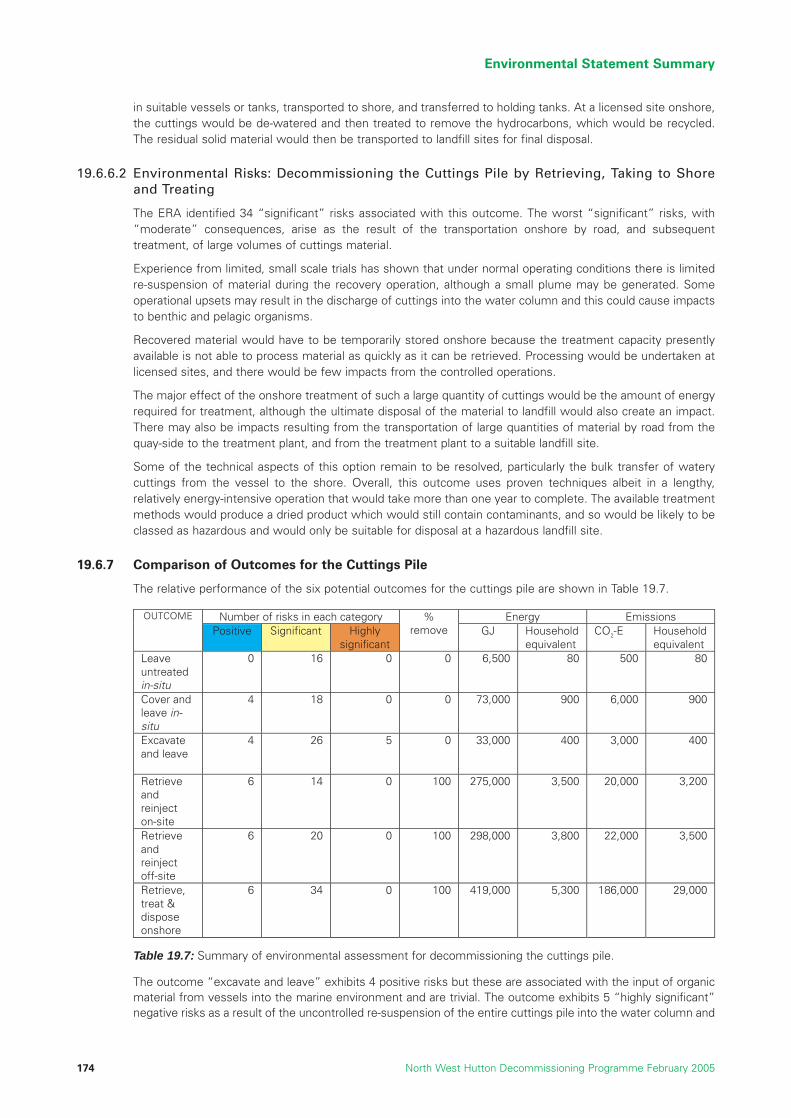
in suitable vessels or tanks, transported to shore, and transferred to holding tanks. At a licensed site onshore,the cuttings would be de-watered and then treated to remove the hydrocarbons, which would be recycled.The residual solid material would then be transported to landfill sites for final disposal.
19.6.6.2 Environmental Risks: Decommissioning the Cuttings Pile by Retrieving, Taking to Shoreand Treating
The ERA identified 34 “significant” risks associated with this outcome. The worst “significant” risks, with“moderate” consequences, arise as the result of the transportation onshore by road, and subsequenttreatment, of large volumes of cuttings material.
Experience from limited, small scale trials has shown that under normal operating conditions there is limitedre-suspension of material during the recovery operation, although a small plume may be generated. Someoperational upsets may result in the discharge of cuttings into the water column and this could cause impactsto benthic and pelagic organisms.
Recovered material would have to be temporarily stored onshore because the treatment capacity presentlyavailable is not able to process material as quickly as it can be retrieved. Processing would be undertaken atlicensed sites, and there would be few impacts from the controlled operations.
The major effect of the onshore treatment of such a large quantity of cuttings would be the amount of energyrequired for treatment, although the ultimate disposal of the material to landfill would also create an impact.There may also be impacts resulting from the transportation of large quantities of material by road from thequay-side to the treatment plant, and from the treatment plant to a suitable landfill site.
Some of the technical aspects of this option remain to be resolved, particularly the bulk transfer of waterycuttings from the vessel to the shore. Overall, this outcome uses proven techniques albeit in a lengthy,relatively energy-intensive operation that would take more than one year to complete. The available treatmentmethods would produce a dried product which would still contain contaminants, and so would be likely to beclassed as hazardous and would only be suitable for disposal at a hazardous landfill site.
19.6.7 Comparison of Outcomes for the Cuttings Pile
The relative performance of the six potential outcomes for the cuttings pile are shown in Table 19.7.
The outcome “excavate and leave” exhibits 4 positive risks but these are associated with the input of organicmaterial from vessels into the marine environment and are trivial. The outcome exhibits 5 “highly significant”negative risks as a result of the uncontrolled re-suspension of the entire cuttings pile into the water column and
Environmental Statement Summary
North West Hutton Decommissioning Programme February 2005174
Number of risks in each category Energy Emissions OUTCOME
Positive Significant Highly significant
% remove GJ Household
equivalent CO2-E Household
equivalent Leave untreated in-situ
0 16 0 0 6,500 80 500 80
Cover and leave in-situ
4 18 0 0 73,000 900 6,000 900
Excavate and leave
4 26 5 0 33,000 400 3,000 400
Retrieve and reinject on-site
6 14 0 100 275,000 3,500 20,000 3,200
Retrieve and reinject off-site
6 20 0 100 298,000 3,800 22,000 3,500
Retrieve, treat & dispose onshore
6 34 0 100 419,000 5,300 186,000 29,000
Table 19.7: Summary of environmental assessment for decommissioning the cuttings pile.
the subsequent covering of a large area of natural seabed by a layer of resettled cuttings. Excavation mightreduce the physical and chemical persistence of the pile material compared to the undisturbed pile, but theimpacts to the seabed, water column, and benthos would be immediate and “major”, and the impacts of theresettled layer of cuttings to the seabed and benthos would be long-term and “major”.
The outcome “cover and leave” exhibits 4 positive risks, again all associated with the input of organic materialfrom vessels into the marine environment, and they are all trivial. The outcome exhibits 18 “significant”negative risks, and with the exception of risks from major accidental oil spills following a collision, theconsequences of all are rated as “minor”. Covering would be expected to reduce, but not completely halt, theslow leaching of contaminants from the pile, and it would provide long-term protection to the surface of thepile from physical disturbance. Degradation of hydrocarbons within the pile would essentially cease, and theexisting burden of contaminants would remain locked within the pile material for a long period of time. Thecover would be over-trawlable, but it is acknowledged that in time the cover would begin to break down underthe influence of natural and anthropogenic forces, and would have to be repaired or replaced. Covering the piletherefore encapsulates the pile and its contaminants (albeit for many centuries) but does not remove or reducethe burden of contaminants.
The outcome “retrieve and re-inject on-site” would result in the removal of the whole pile from the seabed,and if executed properly would provide a single, complete solution for the management of the pile. However,this outcome would not currently be allowed in the UKCS under international conventions. Two of its positiverisks are important, the exposure of “natural” seabed for further recovery and colonisation, and the removalof a feature on the seabed that may have an effect on commercial fishing operations. These positive risks arecommon to the other outcomes “retrieve and re-inject off-site” and “retrieve and dispose onshore”, but couldonly be realised if the whole of the footings were also removed.
The outcome “retrieve and re-inject on-site” exhibits 14 “significant” negative risks, including a “moderate”impact to the water column caused by the re-suspension of cuttings during retrieval, and “moderate” impactsto the water column and seabed if retrieved cuttings were accidentally spilt into the sea. These potentialimpacts could arise during ongoing operations spread over many weeks, and as such would be amenable totight control, management intervention, and development and improvement in the procedures and techniquesused. It could therefore be expected that both the “planned” risk (re-suspension of cuttings during retrieval)and the “unplanned” risk (spillage of cuttings back into the sea) could be reduced further to very low levels.The outcome would use about 30 times more energy than the least energy-intensive outcome (“leave in-situ”), but this is a “one-off” cost for the final elimination of the pile as source of environmental risk.
The outcome “retrieve and re-inject off-site” has the two important positive risks as discussed above. Thisoutcome has 20 “significant” negative risks, somewhat more than the “on-site” outcome. This is because off-site re-injection would involve more handling, storage and transportation of the cuttings, with a consequentlyhigher risk of accidental spillage into the sea. This difference aside, the outcome offers all the positive aspectsof on-site re-injection and also has the benefit of not requiring new wells to be drilled. Using the assumptionsstated in this EA off-site re-injection would, however, use about 8% more energy than as on-site re-injection.This outcome would also not be currently allowed in the UKCS under international conventions or UK law.
The outcome “retrieve and dispose on shore” again has two positive risks that are important, as discussedabove. This outcome exhibits a total of 34 “significant” negative risks, nearly twice as many as the outcome“retrieve and re-inject off-site”. In addition to the risks associated with the re-suspension of cuttings and theirtransportation at sea, this outcome incurs risks relating to the storage, treatment, transportation and finaldisposal of cuttings onshore. As such it exhibits potential risks to individuals, communities and infrastructureonshore; there is greater scope in this outcome for accidental spillages, including into near-shore or coastalwaters, and on land. It is possible that large amounts of material may have to be transported by road totreatment or disposal sites, and while the environmental impacts of road transport may be commonplace, thisoutcome may result in a specific period of heightened activity at a particular site. The status of cuttingsmaterial after treatment to remove hydrocarbons remains problematical, but it is likely that all the residualmaterial would be classed as hazardous waste. If this were the case, a new landfill site would have to beconstructed in Scotland or the waste would have to be transported to a site in England. This is the mostenergy-intensive outcome for the cuttings and would use about 40% more energy than “retrieve and re-injectoff-site”; this may be a significant difference given the method used to calculate energy use. In addition,because the cuttings would be treated onshore, this outcome may result in 8 times the level of O2-E emissionsof the next outcome, retrieve and re-inject off-site.
The outcome “leave in-situ” exhibits 16 “significant” risks, approximately the same number as the outcomes“cover and leave” and “retrieve and re-inject on-site”. The physical presence of the pile, the potential effects
Environmental Statement Summary
North West Hutton Decommissioning Programme February 2005 175

of disturbance and spreading by over-trawling, would all result in risks that had a “moderate” consequence.The seabed, benthic community, water column, pelagic community, and commercial fishing could all beaffected to varying degrees by the long-term presence of the pile and its contaminants. This is the leastenergy-intensive of the outcomes.
It is therefore concluded that, from an objective consideration of potential environmental impacts, and bearingin mind the site-specific characteristics of the North West Hutton pile and environment, the outcome for thecuttings pile that offers the least environmental impact would be “leave in-situ”. The pile is presently stable,and the rate of leaching of oil is very low. The seabed around the edge of the pile is recovering from the impactsassociated with the historic discharge of cuttings, and this recovery will continue. The pile itself would continueto degrade very slowly over a long period of time. Its continued presence at the North West Hutton site wouldnot affect any sensitive marine environments, or any rare or sensitive species, and would be unlikely to resultin any effects on the marine food chain. The agreed monitoring programme would be able to detect changes inthe characteristics, nature and effects of the pile as it ages. If the outcome for the footings is “leave in-situ”then the presence of the footings with clear marine chart marking and other measures would help to minimisethe possibility of accidental physical disturbance of pile material by bottom-towed fishing gear. Furthermore, ifthe footings were to be left then the two important positive risks associated with all three of the “removal”outcomes for the pile – exposure of the natural seabed and removal of a feature that might interfere withcommercial fishing - would not be realised.
19.7 Decommissioning the Pipelines
There are three main outcomes for the two pipelines. All the outcomes, and the methods of achieving thoseoutcomes, are feasible for both the 10” trenched gas import pipeline and the 20” untrenched oil exportpipeline. Both pipelines will have been thoroughly cleaned before decommissioning, and so nodecommissioning outcomes will release any significant amounts of hydrocarbons into the sea.
19.7.1 Leave in-situ
19.7.1.1 Outcome: Decommissioning the Pipelines by Leaving in-situ
The lines would be left in-situ, without treatment and filled with seawater, and their condition would bemonitored periodically in an agreed programme. The 10” line would be more or less completely buried withsediment, whereas the 20” line would sit on the seabed. The lines would slowly deteriorate over a longperiod of time.
19.7.1.2 Environmental Risks: Decommissioning the Pipelines by Leaving in-situ
The 10” trenched line would eventually collapse into its existing trench. The presence of the line and its slowdegradation would not result in any significant impacts to the seabed or the pelagic or benthic communities.The line would pose some risk to bottom-towed fishing gear, but this would be small because over 70% ofthe line is already covered by sediment that has naturally back-filled into the trench.
The 20” line would also collapse, but this would not cause significant impacts in the pelagic or benthiccommunities. Because this line is located on the surface of the seabed, its collapse would create a line ofdebris (concrete and steel) that would be more prone to interaction with towed fishing gear.
The ERA identified 3 “significant” risks associated with this outcome. The worst “significant” risk, with a“moderate” consequence, would be the socio-economic consequences for fishermen of the presence ofmaterial on the seabed.
19.7.2 Trench and Bury
19.7.2.1 Outcome: Decommissioning the Pipelines by Trenching and Burying
The oil pipeline would be buried using a towed plough to ensure that it was covered by at least 0.6m of seabedsediment. The gas line would be remedially trenched by plough or other appropriate equipment. Remedialtrenching would be undertaken on those sections that presently exhibit spanning, to ensure that they werecompletely buried in the sediment.
Environmental Statement Summary
North West Hutton Decommissioning Programme February 2005176

19.7.2.2 Environmental Risks: Decommissioning the Pipelines by Trenching and Burying
Clean sediment would be thrown up into the water column during the burial operations, but this would causenegligible impact. The vessels used in the operation would create gaseous emissions. Burial would result inpotentially recyclable material not being retrieved from the sea. Resources would be needed for periodicinspections and for potential remedial activities in the future.
A small area of the seabed along the length of each line would be disturbed, and the benthic communitiesthere would be destroyed. Where pipelines are buried by part of the cuttings pile, some contaminatedsediments would be dispersed into the water column, but these impacts would be localised and transient.Once the lines were buried with natural sediment, benthic communities typical of the area would quicklybecome re-established.
The ERA identified 9 “significant” risks associated with this outcome, none of which had a consequence ratedworse than “minor”.
19.7.3 Remove and Dispose Onshore
19.7.3.1 Outcome: Decommissioning the Pipelines by Removing and Disposing Onshore
Several methods are available for the total removal of both lines, and for the 10” line the existing over-burden ofsediment would have to be removed by dredging or water-jetting before the pipeline could be lifted. However,all of the possible methods result in the complete pipeline being retrieved to the surface, taken to shore, anddisposed of by recycling and other appropriate routes. The seabed on both routes would be left clear for fishing.
19.7.3.2 Environmental Risks of Decommissioning the Pipelines by Removing and Disposing Onshore
All the removal methods would result in a small number of minor impacts to the seabed and benthiccommunities immediately adjacent to the pipeline. Where pipelines are buried by part of the cuttings pile,some contaminated sediments would be dispersed into the water column, but these impacts would belocalised and transient.
19.7.4 Comparison of Outcomes for the Pipelines
There are three possible outcomes and their performance is shown in Table 19.8.
None of the outcomes for the pipelines would exhibit a negative risk that would be rated as “highlysignificant”. All three outcomes exhibit about the same number of positive risks, but in the outcomes “trenchand bury” and “retrieve and dispose onshore” two of the positive risks are important, namely thereestablishment of natural sediment for the colonisation of benthic communities, and the removal of apotential obstruction to fishing from the seabed.
The outcome “leave in-situ” has 5 positive risks but they are all trivial. It exhibits the smallest number of“significant” negative risks, but the risk of entanglement with fishing gear the risk is rated as “moderate”, andthis is an important factor in assessing this outcome. The outcome has the lowest energy use and given themethod used to estimate energy use the difference between this outcome and the next (“trench and bury”)may be significant.
The outcomes “trench and bury” and “retrieve and dispose onshore” accomplish one similar outcome,namely the removal of the pipelines from the seabed and their consequent elimination as a potential
Environmental Statement Summary
North West Hutton Decommissioning Programme February 2005 177
Number of risks in each category Energy Emissions OUTCOME
Positive Significant Highly significant
% remove GJ Household
equivalent CO2-E Household
equivalent Leave untreated in-situ
5 3 0 0 113,000 1,400 8,000 1,300
Trench and bury
6 9 0 0 150,000 1,900 11,000 1,700
Retrieve and dispose onshore
6 12 0 100 193,000 2,400 14,000 2,200
Table 19.8: Summary of environmental assessment for decommissioning the pipelines.

snagging feature for commercial fishing operations. They exhibit 9 and 12 “significant risks” respectively; thedifference should be treated with caution because the additional risks for “retrieve and dispose onshore”arise from a presumed worst-case accidental oil spill from the recovery vessel at a location close to the coast.With the exception of these spill risks, all the “significant” risks in both these outcomes were rated as having“minor” consequences at worst. The outcome “retrieve and dispose onshore” has a higher use of energy,and a greater amount of CO2-E emissions than “trench and bury”, and the differences in both thesemeasures (about 30%) may be significant within the context of the method used and assumptions made tocompute energy and emission values. The outcome “retrieve and dispose” is therefore unlikely to result inany real energy or emissions savings.
From our assessment of the environmental risks, the outcome for the pipelines that offers the leastenvironmental impact would be “trench and bury”. Although it has more “significant” negative risks thanleave in-situ, it is suggested that these additional risks, which would be short-term and localised, areoutweighed by the important positive effect of removing the pipelines permanently from the surface of theseabed and thus eliminating any possible interaction over the long-term with bottom-towed fishing gear.
References
19.1 “Report ENV01”, BMT Cordah Ltd, Environmental Statement in support of the De-commissioning of theNorth West Hutton Facilities, Report No. BPX067/ES/2003, June 2004.
19.2 BSI, 1996. BS 8800:1996 A Guide to Occupational Health and Safety Management Systems, BritishStandards Institution, London.
19.3 DTI, 2003. Oil & Gas. http://www.og.dti.gov.uk/.
19.4 BP, 2000. Magnus Enhanced Oil Recovery (EOR) Project Environmental Statement. D/1039/2000.
19.5 BP, 2001. Clair Phase I Development – Environmental Statement for Offshore Activity. D/1228/2001.
Environmental Statement Summary
North West Hutton Decommissioning Programme February 2005178

20 APPENDIX
20.1 Letter to Interested Parties
20.2 Report of 6th February 2003 Stakeholder Meeting
20.3 Report of 12th June 2003 Stakeholder Meeting
20.4 Report of 6th May 2004 Stakeholder Meeting
20.5 List of Comparative Assessment Studies
20.6 Report by the Independent Review Group (IRG)
20.7 Longitudinal Profiles
20.8 Summary of Applicable Legislation
Appendix
North West Hutton Decommissioning Programme February 2005 179

Appendix
North West Hutton Decommissioning Programme February 2005180

20.1 Initial Letter to Interested Parties
Appendix
North West Hutton Decommissioning Programme February 2005 181
Norrie RamsayProjects & Decommissioning Manager Northern Business Unit BP Exploration Operating Company Ltd
Burnside Road Farburn Industrial Estate Dyce Aberdeen AB21 7PB
29 November 2002
«Mr» «Initial» «Surname» «Job_Title» «Address1» «Address2» «Address3»
Direct 01224 835284 Main 01224 832000 Fax 01224 834523 Mobile [email protected] www.bp.com
Dear «Mr» «Surname»
NORTH WEST HUTTON DECOMMISSIONING
I am writing to inform you that BP has started preparations for decommissioning the NorthWest Hutton oil field, located some 130 km North East of the Shetlands Islands.
Continuing investment in North West Hutton in recent years by BP and co-venturers CIECO Exploration and Production (UK) Ltd, Mobil North Sea Ltd and Enterprise Oil UK Ltd, has been successful in extending field life beyond previous expectations. However, low levelsof production mean the field is now uneconomic and the technical and commercial case for ending production has been accepted by the Department of Trade and Industry.
The field is currently shutdown and well abandonment work is underway. This work will continue into next year and preparations are also being made for a topsides clean upprogramme scheduled to begin early next year.
Platform removal will not begin until we have completed comparative assessments for thekey removal and disposal options, investigated alternative uses and submitted a fulldecommissioning programme acceptable to the DTI. In carrying out these assessments, we will take into consideration safety and the availability of suitable technology as well asthe environmental, economic and social impacts of the different removal and disposaloptions.
We also intend to consult widely with all who have an interest in the decommissioning of North West Hutton and invite you to take part in this consultation process.
If you are interested in taking part, I would be grateful if you could complete the attachedform and return it to Richard Grant at the above address, by fax to 01224 832841 or bye-mail to [email protected], so that we can establish a stakeholder consultation register.Please pass the form to anyone else in your organisation who might be a more appropriatecontact for consultation.
ARCO British Ltd Amoco (U.K.) Exploration Company Inc. with limited liability inInc. with limited liability in Wilmington Delaware, USA, No. 722013007
BP Exploration Operating Company Ltd Delaware, USA, No. 05438-27 Branch Reg. In England No. BR001713 Registered in England & Wales No. 305943 Branch Reg. in Scotland No. BR005086 Reg. Branch Address: Breakspear Park,Registered Office: Britannic House, Reg. Branch Address: Burnside Road, Farburn Breakspear Way, Hemel Hempstead,1 Finsbury Circus, London, EC2M 7BA Industrial Estate, Dyce, Aberdeen, AB21 7PB Herts., HP2 4UL

Appendix
North West Hutton Decommissioning Programme February 2005182
- 2 -
In the meantime, a fact-sheet on North West Hutton is enclosed with some background on the history and size of the field and we also intend to set up a website where new information and progress updates on decommissioning will be posted. Information on allaspects of BP, including our North Sea operations, can be found at www.bp.com.
Yours sincerely
Dr Norrie RamsayDecommissioning Manager
To:
Norrie Ramsay/Richard GrantEast Production Unit – NW Hutton Decommissioning Team BP Burnside Road Farburn Industrial Estate Dyce Aberdeen AB21 7PB
Fax No 01224 832841
I am interested / not interested in taking part in consultation with BP on the decommissioning of the North West Hutton installation.
NAME ………………………………………………………………………………
ORGANISATION………………………………………………………………….
ADDRESS …………………………………………………………………………
TEL ………………………….. FAX ……………………………………………
E-MAIL ……………………………………………………………………………
My main areas of interest are:
Environmental Impact Social Impact
Safety Economic Impact
Sustainable Development Technology
Other (please specify) …………………………………………………………….
Signed ………………………………… Date ……………………….
Data Protection Statement
Your contact details are securely held by BP and will be treated confidentially as part of our consultation process on North West Hutton decommissioning.
Appendix
North West Hutton Decommissioning Programme February 2005 183
20.2 Report of 6th February 2003 Stakeholder Meeting
BP STAKEHOLDER MEETING
N.W. HUTTON DECOMMISSIONING CONSULTATION
6th February, 2003
Aberdeen
Produced by
ForthRoad LimitedThe BoathouseSilversandsHawkcraig RoadAberdourFife KY3 OTZTel : +44 1383 861023Fax : +44 1383 860884Email : [email protected] : www.forthroad.com
Appendix
North West Hutton Decommissioning Programme February 2005184
INTRODUCING FORTHROAD
ForthRoad Limited has prepared this report under contract to BP. ForthRoad is a specialist organisationaldevelopment consultancy experienced in organising and facilitating workshops bringing together people withsimilar interests to consider key issues and progress within that. Further information about ForthRoad isavailable through its web site: www.forthroad.com.
Document Contents i
Welcome And Context Setting – Norrie Ramsay, Decommissioning Manager 2
Decommissioning Context Presentation – Steve Johnston,Decommissioning Team Leader 3
Comparative Assessment Studies - Andy Foster, Senior Environmental Advisor& Glyn Harris, Decommissioning Project Manager 4
Syndicate Session 5
Table One 5
Table Two 7
Table Three 8
Additional Issues 9
Future Consultation 10
Appendix One: Participants’ Feedback 11
Appendix Two: List Of Participants 12
Appendix Three: Syndicate Group Flipcharts 13
Group One 13
Group Two 14
Group Three 15
WELCOME AND CONTEXT SETTING – NORRIE RAMSAY, DECOMMISSIONING MANAGER
Norrie addressed the purpose of the stakeholder consultations. He talked about the dilemmas facing BP in thisrespect with competing priorities from different issues such as safety, technical ability, environmental andsocietal impact, and economics. He hoped that these sessions would help BP understand the issue better andproduce a better solution at the end of the day.

Appendix
North West Hutton Decommissioning Programme February 2005 185
DECOMMISSIONING CONTEXT PRESENTATION – STEVE JOHNSTON,DECOMMISSIONING TEAM LEADER
Steve Johnston gave an overview presentation outlining the background to decommissioning, North WestHutton status, current legislation, the decommissioning schedule and key challenges.
A copy of this presentation can be accessed using this web link:http://www.bp.com/location_rep/uk/bus_operating/nw_hutton_decom/index.asp
The presentation was followed by table discussions. A number of the key questions from each table areaptured here together with the BP answers given on the day:
• Does BP have a corporate position on decommissioning in general?Yes – there is a section on our public website. This is underpinned by BP’s Group Policies, commonlyknown as ‘What We Stand For’ covering a number of areas including HSE performance.
• Did the original design and development of North West Hutton in the early 80s take account ofdecommissioning requirements?It was designed in line with regulations in force at the time. It was not possible to anticipate howexpectations and regulations would change through field life
• Are all of the co-venturers in agreement with BP’s approach to NWH decommissioning andstakeholder consultation?Yes – and there are regular meetings to discuss all aspects of our plans.
• Does derogation apply to drill cuttings and pipelines?No – only to the jacket footings.
• Why is recycle rather than re-use the plan for North West Hutton?The age, design and size of the installation mean it is not possible to take it to a new location for re-use as an operational platform. Certain components may be suitable for reuse and theseopportunities will be pursued.
• Is single lift a possibility for the installation rather than removing smaller pieces?Single lift technologies are being researched but none is yet developed.
• What is the timeline for submission of the decommissioning programme to the DTI? We expect that the first draft will be submitted by the end of 2003.
• Is there a drilling template under the cuttings pile and can it be removed withoutdisturbing the pile?There is a template – approximately 12 metres square and 3 metres high. The cuttings pile would needto be moved to gain access to the template.
• What are the dimensions of the cuttings pile?Approximately 160m by 120m and 5m high at the peak.
• What is the height of the jacket footings?Approximately 40 metres.
COMPARATIVE ASSESSMENT STUDIES - ANDY FOSTER, SENIOR ENVIRONMENTALADVISOR & GLYN HARRIS, DECOMMISSIONING PROJECT MANAGER
This presentation focused on comparative assessment studies on the options for pipelines, drill cuttings pileand jacket footings and the independent review process.
This presentation can be accessed at: http://www.bp.com/location_rep/uk/bus_operating/nw_hutton_decom/index.asp
The following points were made and questions posed during the plenary discussion:
QUESTION: Will BP be specific in the DTI submission about where components of the topside and jacket willbe taken following their removal?ANSWER: BP stated that whilst this could be stated “in principle” this would not be possible in detail untilafter DTI approval was obtained and contracts outlining the detail of these activities could be entered into.
• There was discussion around the environmental studies that had been carried out on the repopulationof marine species, following the end of drilling operations and the discharge of drill cuttings on N.WHutton some 10 years previously. There were questions as to whether these studies had beenpublished. It was felt that the amount of data available and the finding about repopulation meant thatN.W. Hutton was well placed in this respect.

• There was conversation about the recent OSPAR meeting on Drill Cuttings Removal. Although therewere differing opinions at that meeting it was not felt that OSPAR, would move to creating a measureimmediately and it is more likely that more research will be required.
• It was also stated that it seemed to make environmental sense to leave the Drill Cuttings rather thanto disrupt the seabed. This also left open the future options where legislation or technology maychange the position.
In the second part of this presentation Glyn Harris discussed Jacket Footings and Pipeline issues.
• A view was expressed that the position on pipelines should be complete removal or burying. Currentdiscussions indicated that where it could be demonstrated that it had been trenched, buried and cabled,this would be acceptable. BP gave some reassurance on the issue of concrete degradation where therehad been a worry that debris from degradation or following removal could create an additional hazard.
• There was discussion around the exact scope covered by North West Hutton Pipelinedecommissioning. BP explained that the SSIV (Sub Sea Isolation Valve) would be removed from the gasimport line. This piece of equipment is within the 500m zone but does not impact the drill cuttings pile.The area to be addressed went up to but did not include the Ninian Tee. It was noted that a morecomprehensive schematic would be helpful and BP undertook to provide this on the web site. TheMaureen example was cited as good practice in this area.
• In response to other questions concerning the status of the pipelines BP confirmed that surveys hadrevealed that there were no spans on the NWH oil export line, that there had been some rock dumpingon the gas line and that the gas line was trenched.
It should be stated that the opinions mentioned here were individuals opinions rather than a consensus but noopposing views were stated in the meeting not mentioned here.
SYNDICATE SESSION
Participants were asked to discuss any issues arising and address the following questions at theirrespective tables:
• Is the comparative assessment process comprehensive and coherent?
• Which of the issues identified by BP are the most critical?
• Are there other issues you wish to raise?
Table One
Table one made the following points following its discussion, talking first about the Comparative AssessmentStudies:
• Generally comprehensive but some areas of uncertainty need to be discussed. This is the stimulus foradditional study. How would BP manage uncertainty? e.g. what if BP were unable to cut something asthey thought. What contingency plans could there be. It was suggested that BP could look at furtherindustry studies to establish these alternatives.
• Comprehensive as any other: nothing new, standard 5 areas, meets the standard.
• There was some discussion around the term coherent. How to get balance between these areas(Social, Economic, Technical, Safety and Environmental).
• No common weighting/metric – safety versus environment. Real challenge to get balance. Cost couldbe a common metric but this was not ideal. How do you put a cost on a Blue Whale or theenvironmental loss of a Salt Marsh compared to the creation of new jobs? There are ways of doing this.
• Could we change the word coherent to rational?
• Is it objective and thorough if subjected to specialist audit – financial, technical, environmental etc? Italso needs to be transparent and holistic.
• Any specialist audit should be conducted by a different set of experts from the BP independent review group.
• The process should be transparent, should learn from previous decommissioning activities and take aholistic approach.
Appendix
North West Hutton Decommissioning Programme February 2005186

Appendix
North West Hutton Decommissioning Programme February 2005 187
• Issues can be separated BUT need holistic assessment. You can separate cuttings, footings andpipelines but in the end you need to bring them back together.
• The assessment will be criticised for bias.
• Derogation imperative will be dominant. North West Hutton will be the first UK only platform wherederogation may be applied. There will have to be a water tight case.
• There are fishing concerns.
• Concerns around re-use, LSA.
Table Two
Table two made the following points following its discussion:
• Economics.
o Explanation of use of public money - decommissioning costs can be offset against tax paidduring operational life of the field. Will people feel they have some sort of stake?
o Monitoring Costs - BP needs to commit to this on an ongoing basis (Cuttings Pile etc)There would have to be contingency planning. What would happen if BP were sold or broken up?
o Liability issues.
• Social aspects.
o Look at job benefits.
o Knock on revenue.
o Waste management sub contactors.
• Public Perception - biggest issue. Whole process and documentation needs to be transparent.
• Perception of the Independent Body: - Could BP provide information on who is on it?
• There needed to be Accreditation of the whole approach. Endorsement of right approach.
Comparative Assessment Studies
• Timing of operation should be assessed - when do you do things to get the best effect. What were therequirements for technical detail? Certain level needed in DTI submission. E.G. Would cutting be bywater-jet or explosives etc (these have different impacts). Generally more detail was welcome.
• Contingency - How do you account for not physically being able to do it?
• Issues weighting.
o Transparent objectives.
o Understandable.
o Feedback with iterative process.
Important Issues
• H&S priority is recognised.
o Others are stakeholder dependent.
• Cost – not exclusion factor but value for money?/Linked to weighting.
Table Three
Table three made the following points following its discussion:
• Political aspects, precedent, reputation do they form another area to be considered and how? Noanswer from the table – this is a huge area. Is it in the CAS or not?
• Issues were discussed on the comparative importance of 5 areas. BP might start at Safety BUTshouldn’t you start at Technology and then do it safely.
• None is more important than the other - different times different lenses.
• The issue of re-use was raised. How would this effect decisions. In the case of steel from the jacket.If we knew a use for it would that change where we took it to after removal.
• “Don’t stop at the quayside” BP should track and measure the impact of ongoing activity andparticularly waste disposal.
Comparative Assessment Studies
• Reasonably comprehensive. How do you draw it all together at the end into one coherent piece?
• Challenge for BP to go beyond the boundary.
• Impact of Policy Framework? – Precedent.
• Political and public perceptions.
• Break open the social bubble.
• How could BP generate a common currency for the 5 elements. Cost not the best way.
• Timing - are we going to be able to complete all the CAS work by the end of the year. Will it be thorough?
• It would be good if the feedback process was iterative rather than everything coming out at the at last minute.
• Health & Safety is very important. BP is a business but cost is not priority issue. Value for money is important.
ADDITIONAL ISSUES
Participants identified the following additional issues:
• Issue of precedent setting.
• Partial removal as an interim state/continuous monitoring.
• Difficult to justify financially as an ongoing commitment.
• Ensure licences are available for onshore contractors as part of the process – no one is bounced.
• Issues of breaking the “Social Bubble” – the 6th Bubble - political, societal, green.
• Timing a big issue.
FUTURE CONSULTATION
• Use topic specific groups, then bring these together to integrate (careful not to isolate).
• Meet when there is something to tell us.
• How to take on the challenge of balancing the 5 issue areas.
Appendix
North West Hutton Decommissioning Programme February 2005188

Appendix
North West Hutton Decommissioning Programme February 2005 189
WHAT WORKED WELL
Good spread of people and good calm thinking
Constructive Process
Background level of detail progression
Mix of people
Lunch
Networking
1st Table Session after Presentations
Brief pre-readRight ApproachRight AgendaRight Duration
WHAT WOULD HAVE BEEN BETTER
Balance more Detail with Integration of Issues
Demands on Time
More on Status of Project in Presentation
Themed Sessions
Vary Location?
Acoustics
Clarity on Stakeholder Process Timetable
Try and get some of the Wider Green 5 here egGreen peace, WWF
to know what they are thinking on this-->Perhaps more Critical
Some assumptions were made eg a lot of talk waskind of assumingEg Drill Cuttings would be left in place
Geoff Anderson ForthRoadMarcus Armes University of East AngliaRon Beard HalcrowJan Bebbington University of AberdeenEric Breuer Scottish Association for Marine ScienceZoe Crutchfield JNCCMike Curtis SEPATracy Edwards JNCCGina Ford RSPBSusan Gass Scottish Association for Marine ScienceRay Johnstone FRS Marine LabMurdo Maciver Shetland Decommissioning CoKostas Rados Robert Gordon UniversityMichael Sutherland Scottish Fishermens FederationJohn Watt Scottish Fishermens FederationAlan Wishart Lerwick Port AuthorityPhil Dyer ShellAndy Foster BPRichard Grant BPGlyn Harris BPGordon Harvey BPSteve Johnston BPSimon Merrett BPNorrie Ramsay BP
APPENDIX ONE: PARTICIPANTS’ FEEDBACKThe following feedback was given by participants:
APPENDIX TWO: LIST OF PARTICIPANTS

APPENDIX THREE: SYNDICATE GROUP FLIPCHARTS
Group One
Group two
Appendix
North West Hutton Decommissioning Programme February 2005190
1. IS COMPARATIVE ASSESSMENT:-
a) COMPREHENSIVE Generally yes but areas of uncertainty need to be discussed Stimulus for additional study
b) COHERENT Depends on approach to achieving balance Weighting -- Metrics
PREFER RATIONAL OBJECTIVE (REF TO AUDIT) TRANSPARENT HOLISTIC
ASSESSMENT (subject to review group scrutiny)
DEROGATION IMPERATIVE
2. FISHING CONCERNS
3. RE-USE, LSA
ISSUES?
ECONOMICS -- PUBLIC MONEY -- MONITORING COST -- LIABILITY ISSUES
COMPANY BREAK-UP?
SOCIAL ASPECT -- ASSOCIATED JOBS-- KNOCK-ON REVENUE
SUB-CONTRACTORS
PUBLIC PERCEPTI ON -- ENSURE TRANSPARENT -- INDEPENDENT BODY
'ACCREDITATION' ? 'ENDORSE
COMPARATIVE ASSESSMENT
TECH DET AIL -- TIMING OPTIONS ? -- LEVEL REQUIRED FOR REAL
ASSESSMENT (eg explosives) -- CONTINGENCY PLANS
ISSUE WEIGHTING -- TRANSPARENT OBJECTIVES -- UNDERSTANDABLE -- FEEDBACK WITH ITERATIVE
PROCESS
IMPORTANT ISSUES
H&S PRIORITY RECOGNISED -- OTHERS STAKEHOLDER DEPENDENT
COST -- NOT EXCLUSION FACTOR BUT VALUE FOR MONEY? -- LINKED TO WEIGHTING

Appendix
North West Hutton Decommissioning Programme February 2005 191
Group three
OTHER ISSUES
Re-use?
considered (on and offshore -use)
Decommission
Assessment process * interaction of aspects of CA (weightings) - all important and depends where you come from
* robust & defendable
* boundaries & responsibilities (e.g. licenses for disposal
-contractors) * break open the social bubble
Other issues in Models
• impact on policy framework
• "political perceptions" "public perceptions"
• risk issues
• common currency of elements

Appendix
North West Hutton Decommissioning Programme February 2005192
Appendix
North West Hutton Decommissioning Programme February 2005 193
20.3 Report of 12th June 2003 Stakeholder Meeting
NORTH WEST HUTTON DECOMMISSIONING
STAKEHOLDER MEETING
BP
Marcliffe Hotel, Aberdeen
12th June, 2003
Produced by
ForthRoad LimitedThe BoathouseSilversandsHawkcraig RoadAberdourFife KY3 OTZTel : +44 1383 861023Fax : +44 1383 860884Email : [email protected] : www.forthroad.com

INTRODUCING FORTHROADForthRoad Limited has prepared this report under contract to BP. ForthRoad is a specialist organisationaldevelopment consultancy experienced in organising and facilitating workshops bringing together people withsimilar interests to consider key issues and progress within that. Further information about ForthRoad isavailable through its web site: www.forthroad.com.
Introducing ForthRoad i
Index ii
Introduction/Purpose 1
NW Hutton Status Update – Steve Johnston 2
Sustainable Development – Jan Bebbington 5
Group One: Jacket & Footings 8
Group Two: Drill Cuttings 9
Group Three: Pipelines 10
Plenary Discussion 11
Feedback About The Meeting 12
BP Remarks & Next Steps – Steve Johnston 13
INTRODUCTION/PURPOSEThe purpose of the meeting was to hear stakeholder views on BP’s developing plans for North West Huttondecommissioning. This meeting was the second stakeholder meeting, the first having taken place on 6th
February 2003. The key issue areas around which consultation is taking place are drill cuttings, jacket footingsand pipelines. The first stakeholder meeting set context around these themes, the second was designed toupdate progress on the Comparative Assessment studies and to consider the decision making process furtherincluding the potential for applying sustainable Development Techniques.
Organisations represented at the meeting were:
Aberdeenshire CouncilAtlantic Frontier Environmental ForumDTI – Oil and Gas Industry Development DirectorateFRS Marine LabJNCCLerwick Port AuthorityNorth West Hutton Independent Study Review GroupOffshore Contractors AssociationPeterhead Bay AuthorityRF Rogaland ResearchRoss DeeptechScottish Fishermens FederationShellShetland Decommissioning CompanyUniversity of East AngliaUniversity of Aberdeen
BP attendees:
Andy FosterRichard GrantGlyn HarrisSteve JohnstonBlair McKay
Appendix
North West Hutton Decommissioning Programme February 2005194
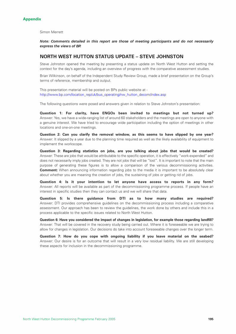
Appendix
North West Hutton Decommissioning Programme February 2005 195
Simon Merrett
Note: Comments detailed in this report are those of meeting participants and do not necessarily
express the views of BP.
NORTH WEST HUTTON STATUS UPDATE – STEVE JOHNSTONSteve Johnston opened the meeting by presenting a status update on North West Hutton and setting thecontext for the day’s agenda, including an overview of progress with the comparative assessment studies.
Brian Wilkinson, on behalf of the Independent Study Review Group, made a brief presentation on the Group’sterms of reference, membership and output.
This presentation material will be posted on BPs public website at -http://www.bp.com/location_rep/uk/bus_operating/nw_hutton_decom/index.asp
The following questions were posed and answers given in relation to Steve Johnston’s presentation:
Question 1: For clarity, have ENGOs been invited to meetings but not turned up?Answer: Yes, we have a wide-ranging list of around 60 stakeholders and the meetings are open to anyone witha genuine interest. We have tried to encourage wide participation including the option of meetings in otherlocations and one-on-one meetings.
Question 2: Can you clarify the removal window, as this seems to have slipped by one year?Answer: It slipped by a year due to the planning time required as well as the likely availability of equipment toimplement the workscope.
Question 3: Regarding statistics on jobs, are you talking about jobs that would be created?Answer: These are jobs that would be attributable to the specific operation, it is effectively “work-expended” anddoes not necessarily imply jobs created. They are not jobs that will be “lost”. It is important to note that the mainpurpose of generating these figures is to allow a comparison of the various decommissioning activities.Comment: When announcing information regarding jobs to the media it is important to be absolutely clearabout whether you are meaning the creation of jobs, the sustaining of jobs or getting rid of jobs.
Question 4: Is it your intention to let anyone have access to reports in any form?Answer: All reports will be available as part of the decommissioning programme process. If people have aninterest in specific studies then they can contact us and we will share that data.
Question 5: Is there guidance from DTI as to how many studies are required?Answer: DTI provides comprehensive guidelines on the decommissioning process including a comparativeassessment. Our approach has been to review the guidelines, the work done by others and include this in aprocess applicable to the specific issues related to North West Hutton.
Question 6: Have you considered the impact of changes in legislation, for example those regarding landfill?Answer: That will be covered in the recovery study being carried out. Where it is foreseeable we are trying toallow for changes in legislation. Our decisions do take into account foreseeable changes over the longer term.
Question 7: How do you cope with ongoing liability if you leave material on the seabed?Answer: Our desire is for an outcome that will result in a very low residual liability. We are still developingthese aspects for inclusion in the decommissioning programme.

Participant Comment: The content of the presentation regarding drill cuttings seems to imply excavation andearth moving. There are better options for doing this.Response: It should be noted that the information presented is a a high level summary. BP participated in thecross industry study about Drill Cuttings. We have looked at a whole range of options and drawn up a shortlist based on those that are applicable to our platform. The range of options has also been independentlyreviewed. However, we would be interested to hear about other options.
Question 8: Have you considered the safety implications and impact in other situations, besides thoseoutlined in the slides? (Risk from Pipelines)Answer: Yes, but the safety impact detailed (in the matrix on the slide) is focused on physical operations work.Risks to other sea users is a very important aspect and is included in our “societal” group of studies.
Question 9: Do you consider the big picture in terms of what new options might be possible in thefuture due to emerging technologies?Answer: The longer term is considered by BP and the rest of the industry through a number of joint industryprojects. However, there comes a time when we need a cut off point and action is required on North WestHutton based on what we know now.
Question 10: Please explain more about the plugging that has been done on the wells.Answer: The wells have all been plugged using two cement plugs deep in each well with a third plug near tothe surface. We have used criteria in excess of standard minimum requirements.
SUSTAINABLE DEVELOPMENT – JAN BEBBINGTON
Jan Bebbington presented on the principles of sustainable development and discussed some models for SDassessment. Jan’s presentation will be posted on the BP public website at - http://www.bp.com/location_rep/uk/bus_operating/nw_hutton_decom/index.asp
The following questions were posed and answers given in relation to Jan Bebbington’s presentation:
Question 1: Regarding the Risk and Policy Analysis model, isn’t it possible that different stakeholdergroups could come up with different weightings for each of the measures?Answer: The final weighting applied is an average of all those provided by the stakeholders. If it is a smallenough group of stakeholders it does not have a major effect but if you were dealing with a large number ofstakeholders some might end up seeing their original weighting disappear when the average is calculated.
Question 2: Do you introduce a discounted cost analysis into the SAM Model?Answer: None of the numbers are weighted, it is not discounted. There are all sorts of enhancements you canadd to the analysis including carrying out geographic analysis of negative and positive impact but it becomesa more complex process.
Question 3: Could the methodology be applied to different energy use options, for example oil fieldversus wind turbines?Answer: It could be applied but it becomes a lot more complex
Question 4: Where do presentation costs figure in the SAM model?Answer: Presentation or reputation isn’t in the model as it stands but that could be made a capital category ifit was seen as crucial.
Question 5: I find the phrase ‘Sustainable Development’ unhelpful. Couldn’t we just call it goodpractice rather than sustainable development?Answer: The models presented have been developed in the context of looking ahead to where things are headingin the future, therefore sustainable development is applicable. However, it could also be seen as good practice.
Appendix
North West Hutton Decommissioning Programme February 2005196

Appendix
North West Hutton Decommissioning Programme February 2005 197
SYNDICATE SESSIONParticipants were organised into three syndicate groups and asked to consider and provide feedback on thefollowing questions:
1. What do you think of the use of sustainable development techniques to aid the decision making process?
2. What other elements might be taken into account?
3. What thoughts do you have around the dilemmas this process reveals?
Each group was asked to consider the questions in relation to one of the following topics:
• Jacket & Footings
• Drill cuttings
• Pipeline
Group One: Jacket & Footings
Group one made the following points in response to the questions:
• Sustainable development is a useful tool but it should not constitute the whole decision makingprocess.
• It could be used with other processes and assessment techniques and conclusions from the sum ofthese tools could be developed.
• The key thing missing is the issue of reputation and how that is managed – sustainable developmentprovides more of a presentation tool, rather than managing reputation.
• An ideal spider-gram (ref Sustainable Development Presentation) with all the appropriate measureswould be useful.
• Avoid complex weighting systems as this only brings about debate. These need to be transparent.
• Using money as the key value judgement could be dangerous – BP might be seen as simply going forthe cheapest option.
• A regulatory element needs to be added.
• Jackets, cuttings and pipelines are all interlinked by critical paths so it is difficult to separate them.
• There are also links between other aspects, such as HSE and the environment.
• A “sustainable solution” is the overall objective.
Group Two: Drill Cuttings
Group two made the following points in response to the questions:
• The group did not think highly of sustainable development techniques. As long as the mechanism isholistic and transparent it doesn’t need to be labelled “sustainable”.
• It might not be possible to bottom out all issues in one document, rather it might make more sense tooffer an interim solution.
• There is clear linkage between all the elements.
• Testing the water of opinion about the preferred approach is key.
Group Three: Pipelines
Group three made the following points in response to the questions:
• Reputation is a big issue.
• Objectivity is key – how do you ensure transparency in the final decision making process?
• It is important to have discussion about the weightings applied and why they have been given a certainweighting i.e. if you ran the same series of discussions on scoring weightings with a range ofstakeholders one or two minor changes can make a massive difference to the bottom lines.
• The system is not closed i.e. a lot of the issues are dependent on others in the box.

• Few areas are independent.
• Why is BP engaging in this exercise? Who is it trying to influence - the stakeholders, DTI or is it justtrying to be seen to be doing the right thing? There was a slight cynicism that sustainable developmentconcept was being seen as a presentational tool.
• The sustainable development framework concept provides at best a contextual “testing mechanism”and should only be seen as one component in decision-making.
• The group approached things from a very simplistic point of view i.e. 3, 2, 1, where 3 was the bestscore for each of the subheadings. The group also applied a weighting to the different issues – againthough very simple this is incredibly subjective. To get an overall score the group merely multiplied theweighting by the score. That meant for this group that the best option was leaving the pipeline in place,followed by trench and bury and lastly recovery and removal. The group however was honest enoughto admit that by changing the weighting by only a few points in some cases you could actually makethese three come much closer together.
• There is a need for a lot more data before we can say whether this technique is robust and reliable e.g.going through the subheadings, an area like energy is not straight-forward. You use energy to recoverthe pipeline with the hope of recycling the steel but is that in itself viable? i.e. you need a lot moreinformation on the market for such recycled steel before making any kind of judgement on the issue.
PLENARY DISCUSSIONA plenary discussion followed the syndicate groups’ feedback and following points were made, questionsposed and responses given.
Question: is there an obligation to remove the pipeline?Answer: No, not in the same way as there is an OSPAR decision on what must be done with redundantinstallations. However, we are investigating the range of possible solutions to ensure that the mostsatisfactory outcome is achieved.
Question: Have options to reuse the jacket been consideredAnswer: Yes, a number of comprehensive and wide-ranging studies have been implemented. However, therelatively remote and hostile location make any opportunities uneconomic. (It should also be noted that therequirement to decommission would still exist).
Question: Are you conducting a reputation risk analysis?Answer: We do a risk review like we do in all other areas of our business; we are constantly assessing thekey risks.
Question: Have you tried to integrate these risks?Answer: We are trying to fully understand the risks to all stakeholders. This is to ensure that the solutionpresented balances the main issues and concerns and is therefore the most widely acceptable and lowest riskoutcome. This meeting is a significant part developing that understanding.
The conversations subsequently widened to include more general comments and feedback, The commentsare those of participants to the meetings and do not necessarily reflect the views of BP.
Participant Comments:
• The group recognised that weightings could be different based on who was conducting the exercise –it might be valuable to have a spread of scores from different perspectives as an aid to making a finaljudgement. Average the weightings and look at incremental difference across the spectrum ofStakeholder weightings?
• Decommissioning should be done as one shot, not in interim stages.
• An interim model would not be acceptable to the DTI at present.
• If cuttings and footings were left in place you (BP) would have to keep monitoring so that this wouldbe an on-going issue.
• Cutting and removal technologies might improve and there needs to be room left to factor that in if thecuttings and footings are left in place.
• We think that either everything must stay, or everything must go – you couldn’t get rid of the installationbut leave the cuttings.
Appendix
North West Hutton Decommissioning Programme February 2005198

Appendix
North West Hutton Decommissioning Programme February 2005 199
• You have flexibility as to what the right approach is but it will be important to put pressure on the DTIto work through issues with you at each juncture. Part of that exploration will have to include NGOs.
• There is a risk to reputation from perceived failure to honour undertakings made to stakeholders and inpublic statements at the time when the original licence to operate was granted. This needs to befactored into the comparative assessment model.
FEEDBACK ABOUT THE MEETING
Participants were asked what went well during the meeting and what could have been done better.
Participants made the following points in relation to the question: what went well?
• Excellent facilitation.
• Workshop table set up is good.
• Good sized groups.
• Presentations round the walls.
• Data/statistics in presentation.
• Good lunch.
• Introducing a wider view is very valuable.
Participants made the following points in relation to the question: what could have been better?
• Work us a bit harder – better use of time.
• Ensure NGO participation – possibly by visiting them.
• Could do with a meetings on the procurement process and timetable.
Question- Assumption is that NGOs come here but to what extent does BP go out to the NGOs?Answer: BP has and will continue to make every effort to meet with all interested parties either at meetingslike this or one-on-one should this be required. We cannot force people to attend.
BP REMARKS & NEXT STEPS – STEVE JOHNSTON
Steve Johnston gave feedback about the output from the meeting and summarised some next steps for BP.This included the following points:
• This meeting has stimulated a great deal of extremely valuable input from participants and it hasgenerated a lot more issues that will be considered.
• The purpose was to give you an update on our progress and gain your feedback and views as to thekey issues and your opinions regarding the decommissioning in light of the progress made.
• It was valuable to have clarity around the Independent Review Group and a great presentation from JanBebbington on sustainable development. We hope that the presentation from the independent reviewgroup and the session on sustainable development added significantly to the meeting andunderstanding of the overall process.
• It seems that sustainable development, put in the correct context, can be a valuable addition to thedecision making process.
• We will formulate thoughts and plans over the next few months and will have some preliminaryproposals by the end of the summer which we would hope the get your views on.

Appendix
North West Hutton Decommissioning Programme February 2005200

Appendix
North West Hutton Decommissioning Programme February 2005 201
20.4 Report of 6th May 2004 Stakeholder Meeting
BP STAKEHOLDER MEETING
N.W. HUTTON DECOMMISSIONING CONSULTATION
Ardoe House, Maryculter, Aberdeen
Thursday 6th May 2004
Produced by
ForthRoad LimitedThe BoathouseSilversandsHawkcraig RoadAberdourFife KY3 OTZTel : +44 1383 861023Fax : +44 1383 860884Email : [email protected] : www.forthroad.com

Appendix
North West Hutton Decommissioning Programme February 2005202
CONTENTS PAGE
CONTEXT 5
INTRODUCING FORTHROAD 5
SUMMARY 5
MEETING DETAIL 6
NORTH WEST HUTTON STATUS UPDATE 6
COMPARATIVE ASSESSMENT PROCESS UPDATE 6
INDEPENDENT REVIEW GROUP FINDINGS 7
SYNDICATE CONTEXT 9
DRILL CUTTINGS COMPARATIVE ASSESSMENT. 11
SYNDICATE SESSION 12
TABLE 1 12
TABLE 2 12
TABLE 3 13
CLOSING REMARKS 14
APPENDIX 15
ATTENDEES 15
BP NORTH WEST HUTTON DECOMMISSIONING TEAM ATTENDEES 15
FORTH ROAD FACILITATORS 15
(TO BE ADDED)
AGENDA
PRESENTATION 1 – NORTH WEST HUTTON UPDATE
PRESENTATION 2 – COMPARATIVE ASSESSMENT PROCESS UPDATE
PRESENTATION 3 – INDEPENDENT REVIEW GROUP FINDINGS

Appendix
North West Hutton Decommissioning Programme February 2005 203
ContextThe meeting was organised in order to:
• Present stakeholders with the main findings from the completed comparative assessment studiesdesigned to identify the best solutions for the pipelines, drill cuttings pile and jacket footings.
• Present the Independent Review Group findings and answer questions about their work.
• Invite stakeholders to discuss the comparative assessment findings and give their interpretation ofwhat they are indicating.
• Outline the timeline and process that will be used to reach a decision on best solutions.
Introducing ForthRoad
ForthRoad Limited has prepared this report under contract to BP. ForthRoad is a specialist organisationaldevelopment consultancy experienced in organising and facilitating workshops bringing together people withsimilar interests to consider key issues and progress within that. Further information about ForthRoad isavailable through its web site: www.forthroad.com.
SummaryThe meeting was attended by 19 stakeholders together with 5 members of the BP project team involved inthe North West Hutton decommissioning project.
The initial part of the day comprised presentations from the North West Hutton Project team on the currentsituation together with a presentation from Professor John Shepherd on the findings of the IndependentReview Group (IRG).
The afternoon was spent in syndicate sessions in order to obtain the views and opinions of the stakeholders.These were shared and debated. In conclusion, the attendees were thanked for their contribution. Theoutcomes and presentations from this meeting will be reported on the North West Hutton public websitewww.bp.com/genericarticle.do?categoryId=97&contentId=2015801
BP also made a commitment that stakeholders would be informed of future actions and key decisions.
Meeting detail
North West Hutton Status Update
Norrie Ramsay, Decommissioning Manager, outlined the progress on decommissioning North West Hutton inthe last three years. The installation sits in 143 metres of water and equals the height of Canary Wharf. It wasoriginally designed to handle 130,000 barrels a day; although peak production was only 80,000 barrels a dayand the field was shut down in 2003, some 20 years after coming on stream.
In terms of the current decommissioning work, well abandonment is complete, with all conductorsrecovered and all wells plugged and the reservoir isolated. The topside pipe work and cabling between themodules is all separated. He reiterated that whatever is decided, North West Hutton will set a standard foranything else that will follow.
It is anticipated that by mid July 2004 the platform will be a normally unattended lighthouse modeinstallation (NUI) until its future is decided. He concluded by saying that decommissioning has taken 3 yearsand £50m to get this far.
This presentation can be viewed on the North West Hutton public websitewww.bp.com/genericarticle.do?categoryId=97&contentId=2015801
There were no questions.
Comparative Assessment Process Update
Glyn Harris from the Decommissioning Project Team said that the Comparative Assessment had been carriedout within the legislative framework. Five criteria have been used to assess impact – Safety, Societal,Environmental, Economic and Technical.

Three issues have been studied -– the oil and gas pipelines, jacket and drill cuttings pile.
1. Pipelines: three options were considered - leave, trench and bury or remove. Remove was discussedin the context of cut and lift, and reverse installation methods.
2. Removal of the jacket: The jacket weighs 18,000 tonnes. The three options considered were fullremoval, cut at sea bed level (top of cuttings pile) , cut at top of footings.
3. Drill Cuttings: The broad options under consideration were – leave in-situ, excavate, cover andremove.
There was only one question:
“When cutting at the top of the footings, how many metres are you looking above sea bed?” The answer was 30/40 metres.
This presentation can be viewed on the website atwww.bp.com/genericarticle.do?categoryId=97&contentId=2015801
Independent Review Group Findings
Professor John Shepherd led this presentation. Copies of the Independent Review Group Report (IRG) wereavailable at the meeting. This can also be viewed on the North West Hutton public website.
He made specific allusion to Annex 4 – a summary of IRG comments on the Comparative AssessmentStudies. He said that considerable detail was available behind the specific comments and could be viewedby contacting BP.
Professor Shepherd then continued to outline the composition of the IRG. He said that they were:
• All professionals whose expertise covered the fields of oceanography, geo technical, hydrology,engineering and marine geo chemistry.
• All academics. No one was employed in Industry although some occasionally carried out consultancy services.
• All paid by BP in the IRG as consultants.
• All retained their independence from BP. This was achieved by the fact that they were academics andalso that they had explicitly retained the right to publish their own comments on the IRG findings,should they disagree with BP.
The purpose of the IRG was seen as a quality control mechanism. The Group has examined and commentedon all reports and assessments without fear or favour. This process has been derived from the Brent Sparlearning highlighting the importance of an independent peer review to ensure public confidence on theconclusions reached.
The process has been to take reports as submitted, to comment on them and then return to the authors fora response on their findings. During the course of the process the IRG has met seven times and been involvedin a number of teleconferences and has reviewed around fifty (50) reports. This has involved one hundred andtwenty (120) man days of work including some revisions and reviews with BP. Not all the IRG members readall the reports. However at least two members reviewed each one. They would then synthesise the reportsand distribute to the rest of the Group. They were all discussed in plenary sessions and consensus wasreached on each.
The IRG has had demonstrable influence on the review process. A number of pieces of work have beenundertaken that would not otherwise have been carried out. For instance, there was concern that BP had notconsidered studying the possibility of cutting the footings immediately above the cuttings pile. It was felt thatit might be technically possible and have some benefits. A number of additional studies were thereforecommissioned by BP to look at the practicality of this extra option.
Another example of the IRG influence was in the cuttings pile modelling. Originally the studies ran the JointIndustry Project (JIP) model. This presented a central case with no indication on the range of uncertainty ofthe results. The IRG wanted to quantify the range of uncertainties in these assessments – particularly relatingto the length of time the pile would persist if left undisturbed. A revised study was subsequentlycommissioned with key parameters agreed.
Appendix
North West Hutton Decommissioning Programme February 2005204

Appendix
North West Hutton Decommissioning Programme February 2005 205
Overall, the IRG has been satisfied with BP and the responses of the contractors who carried out the studiesThere have been no stand offs. In conclusion, the IRG believes the final study is free of significant errors ormisrepresentations. It believes the range of areas covered is fine, the scope of the studies is adequate, thatthe job has been done sufficiently well to be fit for purpose.
The IRG has some advice for BP and others:
• Potential rate of recovery and recolonisation of the cuttings pile should not be overstated.
• Levels of confidence in qualitative predictions of the outcomes should not be over stated.
• The IRG see no reason why the cuttings pile should be a major long term threat to the marineenvironment. Small quantities of Anoxic sediments are not uncommon in marine environments.
Professor Shepherd concluded by saying that it must be recognised that selecting the final option has to bethe combined responsibility of BP and the Regulator.
There were a number of questions:
– Q: “Has this group done a review of similar activities that have taken place before or currently?”– A: “All but one of the Group were involved in reviewing the studies carried out for the UKOOA drill
cuttings JIP Programme. Several of us have provided decommissioning advice on projects such as theMaureen report submitted to DTI”.
– Q: ”Have you considered the environmental impact of removing drill cuttings?”– A: “The result of removal operations would be to create a semi natural scar on the seabed.”
– Q: “It was commented that the European involvement in the IRG was a good thing”.
– Q “Have you reviewed the possibility of changing hydrodynamics affecting cutting pile over a period of time?”– A: ”Main hydrodynamics are tidal and this is the biggest factor. The Env 04 study covers hydrodynamics
although it is not a detailed study as it was not thought it would be a major factor. The biggestenvironmental change would be a new Ice Age!”
– Q “Can the Review Group be sure that all other engineering issues have been considered?“– A: “Our function is to review not do studies. We have two (2) engineers and a further member with
an Engineering background on the IRG who are satisfied that all aspects have been covered. Wedid far more work on engineering than anticipated up to TEC 29 – more than any other area. In fact,we had several closed sessions together with some quite active, lively, face to face sessions withBP and the Contractors.”
The presentation of the IRG concluded here. The slides for this presentation can be viewed on the North WestHutton public website on bp.com
Syndicate Context
Norrie Ramsay kicked off this session and was followed by Glyn Harris and Katie Denny who summarised thedata which the studies had developed.
Norrie Ramsey repeated that the object of the meeting was to get everyone’s input – in effect “to help BPchoose between oranges and apples. The delegates now know exactly where BP has got to on the NorthWest Hutton project. Around £50 million has been spent by BP so far. Everyone has a view on this project;inevitably there will be diversity of opinion.
North West Hutton is the first decommissioning project of this magnitude and complexity so far in the North Sea.So, BP cannot look to lessons learned. He said the meeting and BP need to look at offshore and onshore aspectsof the impact of their decisions fully. This is an International issue. Some of the contractors with critical skills andexperience in this area are based in Norway; some are Dutch, Italian, and American and so on.
He stated that in being first, the Project is creating a legacy for the industry. He extolled the group to look atthe big picture and the sustainability issues and not to just look at this project in isolation. He emphasized itscomplexity and acknowledged that these issues were emotive but insisted that this was the delegates’opportunity to influence the outcome.
Norrie went on to emphasize that this was not academic exercise. The decision affects real lives. It covers bigissues such as the potential loss of life. There are a number of safety issues which BP owns and that means
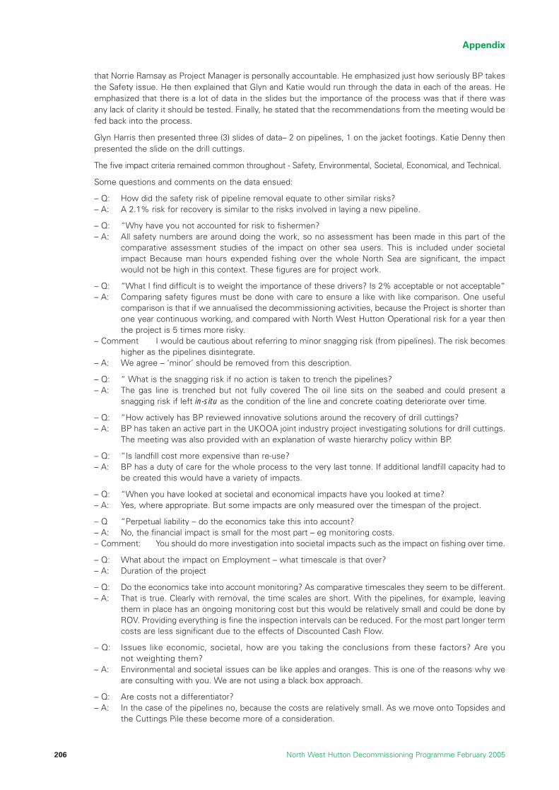
that Norrie Ramsay as Project Manager is personally accountable. He emphasized just how seriously BP takesthe Safety issue. He then explained that Glyn and Katie would run through the data in each of the areas. Heemphasized that there is a lot of data in the slides but the importance of the process was that if there wasany lack of clarity it should be tested. Finally, he stated that the recommendations from the meeting would befed back into the process.
Glyn Harris then presented three (3) slides of data– 2 on pipelines, 1 on the jacket footings. Katie Denny thenpresented the slide on the drill cuttings.
The five impact criteria remained common throughout - Safety, Environmental, Societal, Economical, and Technical.
Some questions and comments on the data ensued:
– Q: How did the safety risk of pipeline removal equate to other similar risks?– A: A 2.1% risk for recovery is similar to the risks involved in laying a new pipeline.
– Q: “Why have you not accounted for risk to fishermen?– A: All safety numbers are around doing the work, so no assessment has been made in this part of the
comparative assessment studies of the impact on other sea users. This is included under societalimpact Because man hours expended fishing over the whole North Sea are significant, the impactwould not be high in this context. These figures are for project work.
– Q: “What I find difficult is to weight the importance of these drivers? Is 2% acceptable or not acceptable“– A: Comparing safety figures must be done with care to ensure a like with like comparison. One useful
comparison is that if we annualised the decommissioning activities, because the Project is shorter thanone year continuous working, and compared with North West Hutton Operational risk for a year thenthe project is 5 times more risky.
– Comment I would be cautious about referring to minor snagging risk (from pipelines). The risk becomeshigher as the pipelines disintegrate.
– A: We agree – ‘minor’ should be removed from this description.
– Q: “ What is the snagging risk if no action is taken to trench the pipelines?– A: The gas line is trenched but not fully covered The oil line sits on the seabed and could present a
snagging risk if left in-situ as the condition of the line and concrete coating deteriorate over time.
– Q: “How actively has BP reviewed innovative solutions around the recovery of drill cuttings? – A: BP has taken an active part in the UKOOA joint industry project investigating solutions for drill cuttings.
The meeting was also provided with an explanation of waste hierarchy policy within BP.
– Q: “Is landfill cost more expensive than re-use? – A: BP has a duty of care for the whole process to the very last tonne. If additional landfill capacity had to
be created this would have a variety of impacts.
– Q: “When you have looked at societal and economical impacts have you looked at time?– A: Yes, where appropriate. But some impacts are only measured over the timespan of the project.
– Q “Perpetual liability – do the economics take this into account? – A: No, the financial impact is small for the most part – eg monitoring costs.– Comment: You should do more investigation into societal impacts such as the impact on fishing over time.
– Q: What about the impact on Employment – what timescale is that over?– A: Duration of the project
– Q: Do the economics take into account monitoring? As comparative timescales they seem to be different.– A: That is true. Clearly with removal, the time scales are short. With the pipelines, for example, leaving
them in place has an ongoing monitoring cost but this would be relatively small and could be done byROV. Providing everything is fine the inspection intervals can be reduced. For the most part longer termcosts are less significant due to the effects of Discounted Cash Flow.
– Q: Issues like economic, societal, how are you taking the conclusions from these factors? Are younot weighting them?
– A: Environmental and societal issues can be like apples and oranges. This is one of the reasons why weare consulting with you. We are not using a black box approach.
– Q: Are costs not a differentiator?– A: In the case of the pipelines no, because the costs are relatively small. As we move onto Topsides and
the Cuttings Pile these become more of a consideration.
Appendix
North West Hutton Decommissioning Programme February 2005206

Appendix
North West Hutton Decommissioning Programme February 2005 207
– Q: If you take this project and multiply over all the other platforms decommissioning how much will thisimpact society as the high cost of decommissioning diverts funds from future investment?
– A: For BP, with a large portfolio and major investment track record this is not a major issue but it may bea factor for smaller companies.
– Q: Tax impact under “society” what does that mean?– A: Some of the tax paid on this field can be recovered by offsetting the costs at the time of decommissioning.
– Q: What do you mean by a 50% risk of not being able to successfully remove the jacket footings?– A: This is an independent assessment of the risk of successfully completing the task of removing the
footings, based on an analysis of the technical challenge and the uncertainties concerning issues suchas the damaged members in the lower part of the jacket, excessive grout around one of the legs etc.
Drill cuttings pile comparative assessment.
Katie Denny then outlined the data for Drill Cutting comparative assessment.
Someone from the floor queried her use of the expression that this has “Never been done before”. It wastheir view this should not be a get out clause. It was clarified that this was in the context of an inability tobenchmark which makes figures less certain.
Other points raised included:
– Disposal of drill cuttings in existing wells may be illegal but should not be a show stopper – ie BP should stillstudy it as an option.
– Dispersal of drill cutting was surely one area where a precedent has been set? It was agreed that this hadbeen done before using the ‘excavation’ method.
Finally, in this session the point was made that the safety of other sea users should be taken into greateraccount. That it would in BP’s interests to capture these risks.
Syndicate Session
Participants were asked to discuss any issues arising and address the following questions at theirrespective tables:
• What is your reaction to the Data?
• What possibilities do you see for resolving some of these dilemmas.
• What would your advice to BP be?
• Are there other issues you wish to raise?
Table 1
Overall the reaction to the data was that it was good news. The Issues that the Table 1 saw were
– Risk & risk transfer. Particularly in the context of other sea users.
– Boundary of analysis – what comes in /what comes out?
– Show stoppers - nothing to stop BP setting up cross industry groups to share knowledge.
Dilemmas? – As a ‘trench & bury’ team, they felt the pipelines solution was clear. However for the drill cuttingspile and particularly the jacket footings, they saw a big dilemma was in the precedent being set for the industry,the impact on other sea users, the changing legal and political environment. In terms of how the 5 criteria wouldbe used as filters, it was clear how the safety criterion would be used but less clear for the others.
Advice for BP? To do what they can now but not closing the door to future technical developments. Toendeavour to use the project to advance industry knowledge. Finally, to make the solution open ended. Then,technology can, at some future date, enable a better solution than currently possible.

Table 2
The group agreed that the data was sufficient for BP to make a decision. They felt that the devil would be inthe detail and would like greater access to it. The use of IRG was to be commended. They believed that theapproach overall was “as good as it can get”.
The group suggested that there was not enough data on onshore treatment. They also believed that theactual technological or scientific information for removal could not be properly analysed with the dataavailable at the meeting.
It was their recommendation to BP that it was important to get closer to the fishermen quickly. It was also feltthat there could be lessons learned from the Maureen experience.
This group also supported the ‘trench and bury’ option and felt that the drill cuttings should be left in place.However they intimated that the eventual outcome would be a political decision.
The Table had no discussion on proposals for the jacket.
Someone from the Floor asked what sort of lessons could be learned from Maureen as the facilitiesare so different?
The answer was that the Maureen decommissioning ran over a few years and generated very little publicinterest. It was felt that media management and communications was paramount. If the case for North WestHutton was not seen to be robust politically and environmentally, it could founder. BP has got to be mindful ofthe wider context.
Table 3
The Group believed the general approach is valid and that the Studies were comprehensive andcompetent. They saw the setting up and involvement of IRG was a positive development that helped tomake the position understandable.
They acknowledged that uncertainties remain. There was a debate about what value there was to be had inrefining them further.
As regards the Comparative Assessment Process, they believed the drivers (safety, societal, environmental,cost, and technical) were not all of the same nature. Safety for example if rigidly applied would rule out thetotal removal and partial footings removal options.
They continued that technical and safety issues combine to present some stretch issues. They are not driversfor choice. “You can do anything you can make anything, as long as you spend enough money”. Ultimately,the major drivers in decision making will be cost and societal perception. The group counselled that Brent Sparmust be remembered - if something goes wrong it will be difficult to get back on track.
The Group considered that both the oil and gas lines should be buried. They believed that both of thesepipelines could be left in place as long as sea bed is proven to be stable and fishing risks are minimised.
The Group also suggested that there was a certain artificiality in the situation. This was because regulation isforcing BP to look at this project in this time frame but not adequately allowing for solutions at a later date.
The Group said that partial removal was a high risk, time-limited derogation was a possible approach. Theyrecommended that BP remove what can be removed currently – ie down to the footings under OSPARderogation but also make a commitment to take account of future developments in technology.
This view made the choice about Drill Cuttings a “no-brainer” as a decision first needs to be made about footings.
Finally, they recommended that creating a good societal case was paramount. The key thrust should be thatas much as possible is being done at the moment and this will get through OSPAR. BP should also becommitted to doing something in future.
Appendix
North West Hutton Decommissioning Programme February 2005208

Appendix
North West Hutton Decommissioning Programme February 2005 209
Closing Remarks
Delegates were asked whether any of them felt that they would like to ask any additional questions, whetheranything had been left unsaid.
Someone asked if anything was said about decommissioning when the platforms were originally put in? Therehas been discussion between the government of the day and some industry areas where assurances hadbeen given around total removal. There was a general floor discussion around the situation that there are nospecific licence issues as long as you complied with the law of the day. When North West Hutton was agreedit was as per the 1958 Geneva Convention - oil companies have to comply with the law of the day.
Norrie Ramsay said that the input from their stakeholders was vital for BP. In his view, the meeting objectiveshad been achieved. With regard to the issues raised around assessing the impact on other sea users and theirconcerns, Norrie stated that this had indeed been addressed and that perhaps in this session this had beenunderstated however he agreed to take this away as an action for BP. In addition, he said he was cognisantthat all societal views were still not represented and they all must be mindful of that.
He concluded that he had taken away three main things from the day:
• The importance of gaining a consensus of views on right decision but building this into context and longterm legacy.
• The Safety of other sea users and the need to test with fishing organisations that BP are getting it right.
• That he had heard the message from the attendees that cost was still a consideration but that societalimpact must be properly assessed.
Finally, he said that the Team will commit to getting back to the delegates on BP’s recommendations whenthese are finalised and that a draft report of today’s meetings would be sent to all delegates for their approvalbefore being published on BP’s website. He also invited any of the delegates to contact the team if they wantedclarification on any of the material raised and thanked them all for their contribution and their time.
Appendix
Attendees
Paul Abernethy – Scottish EnterpriseMarcus Armes – University of East AngliaRichard Austin - IMCAJan Bebbington – University of AberdeenDave Bevan – National Federation of Fishermen’s OrganisationsEric Breuer – Scottish Association for Marine ScienceZoe Crutchfield – JNCCMichael Curtis – SEPAPhil Dyer – ShellPaul Dymond – UKOOAMichael Forman – Fishermen’s Association LimitedMark Gordon – Aberdeen City CouncilRay Johnstone – FRS Marine LabAlasdair McIntyre – Atlantic Frontier Environmental ForumDonald Mc Kernie – Highlands & Islands EnterpriseJohn Shepherd – Independent Review GroupMichael Sutherland – Scottish Fishermen’s federationJohn Watt – Scottish Fishermen’s FederationGraham White - DTI
BP North West Hutton Decommissioning Team Attendees
Katie DennyRichard Grant Glyn Harris Howard KeithNorrie Ramsay
Forth Road Facilitators
Geoff AndersonKanthi Ford

Appendix
North West Hutton Decommissioning Programme February 2005210
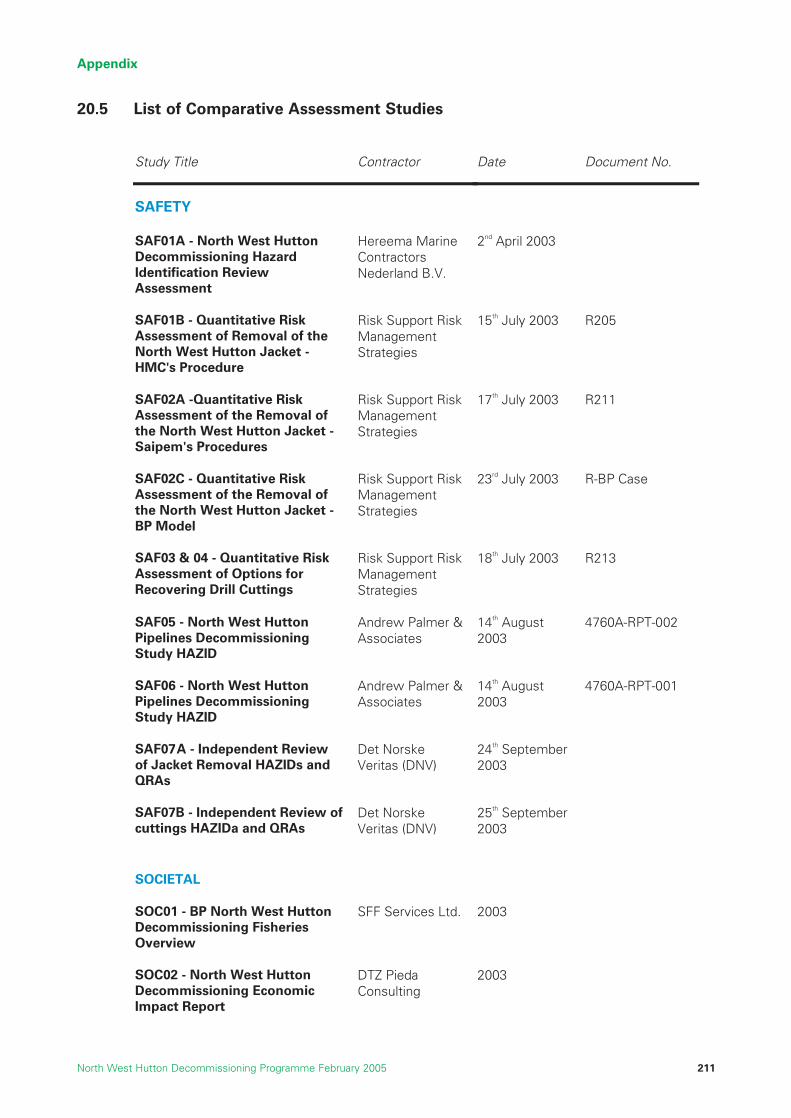
Appendix
North West Hutton Decommissioning Programme February 2005 211
20.5 List of Comparative Assessment Studies
Study Title Contractor Date Document No.
SAFETY
SAF01A - North WDecommi
Hereemest Huttonssioning Hazard
Identification Review
a Marine Contractors
2nd April 2003
titative Risk Assessment of Removal of the
cket -
Risk Support Risk Managem t
15th July 2003 R205
SAF02A -Quantitative Risk oval
ck
Risk Supp Risk
gies
17th Ju 2003 R211
SAF02C - Quantitative Risk al
on JackBP Model
Risk Supp Risk
tegies
23rd Ju 2003 R-BP Case
ive Rt of Options for
Recovering Drill Cuttings
SuppManagement Strategies
18th July 2003 R213
rth West Hutton Pipelines Decommissioning
Andrew Palmer & Associates
14th August 2003
4760A-RPT-002
06 - North West Hutton Pipelines Decommissioning
Andrew Palmer & Associates
14th August 2003
4760A-RPT-001
SAF07A - Independent Review AZIDs and
QRAs
Det Norske Veritas (DNV)
24th September2003
Review of s HAZIDa and QRAs
Det Norske Veritas (DNV)
25th September2003
SOC01 - BP North West Hutton Decommissioning Fisheries Overview
SFF Services Ltd. 2003
SOC02 - North West Hutton Decommissioning Economic Impact Report
DTZ Pieda Consulting
2003
Assessment
SAF01B - Quan
Nederland B.V.
North West Hutton JaHMC's Procedure
enStrategies
Assessment of the Remthe North West Hutton JaSaipem's Procedures
ofet -
ManagemStrate
ort ent
ly
Assessment of the Removthe North West Hutt
ofet -
ManagemStra
ort ent
ly
SAF03 & 04 - QuantitatAssessmen
isk Risk ort Risk
SAF05 - No
Study HAZID
SAF
Study HAZID
of Jacket Removal H
SAF07B - Independentcutting
SOCIETAL

Appendix
North West Hutton Decommissioning Programme February 2005212
Study Title Contractor Date Document No.
ENV01 - Environmental ImStatement in supp
West Hutton facilities
ENV02 - Energy anReport for the Decomof North West Hutton
ENV03 - Evaluation of th
ning Limit
coral Lophelia pertusa oNorth West Hutton
e
BMT Cordah stENV04 - North West HuttCuttings Pile Mo
ENV05 - Analysis of samcollected from cuttin
BM ah 30th June 2004 BP
ENV06 - Pipeline Cleanl
ENV08 – L
North West Hutton pla
TECHNICAL
TEC01 - Life Assessme
TEC02A - North West HuSubs
Detailed Removal Meth
TEC02B & SAF01A - No
Year 2003 Refre y20
ENVIRONMENTAL
pactort of the
Decommissioning of the North
BMT Cordah Limited
June 2004 BPX067/ES/2003
d Emissions missio
BMT Cordah ed
2003
edistribution of the cold-water
n thPlatform
BMT Cordah Limited
11th March 2003
BPX54/NWH/05
on deling Limited
31 March 2003
280000/03
plesgs pile at
North West Hutton
T CordLimited
X45/NWH/04
inessAssessment / Assurance
ong-term Trends in Seabed Disturbance around the
tform
J.P. Kenny
BMT Cordah Limited
11th November 2003
2004
02-2416-01-0-3-002
BPX54/NWH/04
nt of Jacket Footings
Corrpro Europe Limited
19th September2003
tton tructure Decommissioning
Comparative Assessmentod
Hereema Marine contractors Nederland B.V.
24th June 2003 G1100-RP01
rth West Hutton Decommissioning Study
shment StudReport
Saipem UK 2003 973000-NWH 03-001
TEC03A - Inspection Report containing Information from Video Logs and Workscope
Subsea 7 14th January 2004
AB-R-RP-01208
TEC03B - Grout Densitometer Removal Proposal
Subsea 7 8th January 2004
AB-T-pp-00109

Appendix
North West Hutton Decommissioning Programme February 2005 213
Study Title Contractor Date Document No.
Comparative Assessment of le Denton
Europe Ltd. 4th Jul 3 A4113/NDE/MG
B/1 TEC04A - Independent
Partial Jacket Removal
Nob y 200
for Complete or Partial ovalrit
14
Package
TEC06 - Alternative RemMethods
l BP June
Footings Removal using Explosives
EngA
g
TEC09 - Study SponsorDecommissioning Technology Forum Jacket Remo
the Task F July 003
TEC10 - North West HuttoDecommissioning Drill CuTransfer Method Study
TEC11 & 1
ngsSc U
Relocating, CAD, and Reof Onshore TreatmentNorth West Hutton Drill
eryLt
TEC13 - North West HuttSynopsis of En
ah ay 20
surrounding Seabed
TEC14 - 18 & E
Summary Report
TEC25 - InvestigationLifting and Footings Options foNorth West Hutton Decommissioning
TEC26 - North Wes
TEC04B- Jacket Removal Study Rem
Global Ma ime 2nd July 2003 GM-22875-0703-08
TEC05 - Jacket Information Aker Kvaerner 13th May 2003 8226-NWH-ST-004
ova 2003
TEC 07 - A Review of Jacket Explosive ineerin
ssociates
234r June 2003
ed by
val
orceIndustry
2
ntti
an Tech K 21st May 2003 J-1090
2 - Technical Review of the Options of Covering,
covof the
Cuttings Pile.
Dredging Research d.
on A vironmental
Studies of the Cuttings Pile and
BMT CordLimited
24th M 04 L3/AB/26(a)/T/OAM/30.4.02/A
NV06 - Pipeline Decommissioning - Te chnical
JP Kenny 21st November 2003
05-2416-01-G-3-011
of Jacket r
Altair Engineering 25th June 2003 BPABD-29-03-R-01
t Hutton Drilling Template & Mud Line Brace Decommissioning - Drilling Template Removal & Brace Cutting Study Report
Technip-Coflexip 4th July 2003
TEC27 - Jacket DamageIdentification & Drill CuttingsPartial Removal Study
Aker Kvaerner 22nd December 2003
8226-NWH-ST-16

Appendix
North West Hutton Decommissioning Programme February 2005214
Study Title Contractor Date Document No.
TEC28A - Removal oWest Hutton Platfor
f the North m -
Overview of the Subsea
Stolt Offsh 14th November 2003
MEC-066-040
utton mmissioning Leg Cutting
Review - Ja cket Leg Cutting
Technip-Coflexip 5th December2003
COWI 26th March 2004
P-058983-A-100
rth Hutton Decommissioning
Project Cost Estimate Summary
BP 14th Ja uary 2004
p Steel Market
BP 2003
n g
Economics of Options
JP Kenny 2003 05-2416-01-P-3-009
ECO07 - North West Hutton Decommissioning Project Long Term Monitoring Requirements
BP 27th August 2003
Operations Rev 1.0
TEC28B - North West HDeco
ore
Study
ECONOMIC
ECO01, 04, 05 and 06 - NoWest
n
ECO03 - Impact on Scra
ECO05 - North West HuttoPipelines Decommissionin
TEC 29 Removal of the North West Hutton Jacket - Quantitative Comparative Assessment

Appendix
North West Hutton Decommissioning Programme February 2005 215
20.6 Report of the Independent Review Group (IRG)
NORTH WEST HUTTON DECOMMISSIONINGPROJECT
REPORT OF THE
INDEPENDENT REVIEW GROUP (IRG)
26 April 2004

Appendix
North West Hutton Decommissioning Programme February 2005216
NORTH WEST HUTTON DECOMMISSIONING PROJECT
INDEPENDENT REVIEW GROUP (IRG)
FINAL REPORT
CONTENTS
Introduction
In January 2003 Professor John Shepherd FRS was invited by BP to establish an Independent Review Group(IRG) of scientists and engineers to examine and comment, in an independent and objective way, on anextensive series of comparative assessment studies relating to the development of proposals for thedecommissioning of the North West Hutton platform in the North Sea. The studies were grouped into fourthemes: technical, environmental, socio-economic and safety. There were six IRG Members, including theChairman Professor Shepherd, together with a Technical Secretary. The IRG first met in March 2003 andcompleted its work in March 2004. The IRG task involved the study and critique of some 40 major reportsrequiring in total an input of about 120 days effort. This report presents the IRG final summary comments onall the Comparative Assessment studies, and an overview and conclusions of the procedure.
Membership
Chairman Prof. John Shepherd, MA, PhD, CMath, FIMA, FRS
Project Co-ordinator Prof. W.B Wilkinson, BScEng, BScGeol, PhD, FICE,
FCIWEM, FGS, CEng, CGeol, F Russ Acad Nat Sci
Members Research Scientist Torgeir Bakke, Cand.real. (MSc equiv.) Marine Biology
Prof. Michael Cowling, BEng, PhD, CEng, CMarSci, FIMarEST, FSUT, MIM
Prof. William Dover, FIMechE, CEng, FINDT
Prof. Dr. Jürgen Rullkötter, Dipl.-Chem., Dr. rer. nat. habil.,
AAPG, DGMK, DGMS, EAOG, GDCh, GS
Secretary Mr Richard ClementsCEng, MIMechE, MIMarEST
Short biographies of the members of the Independent Review Group are given in Annex 1.
Introduction 4
Membership 4
Terms of Reference 5
Activities of the Independent Review Group 5
Overall Evaluation and Conclusions/Recommendations 6
Annex 1 – Members’ Biographies 9
Annex 2 - Terms of Reference 13
Annex 3 - Activities of The Independent Review Group 14
Annex 4 –Summary IRG Comments on the Comparative Assessment Studies 20

Appendix
North West Hutton Decommissioning Programme February 2005 217
Terms of Reference
The terms of reference of the IRG are given in full in Annex 2.
Activities of the Independent Review Group
The IRG met on 8 occasions, on the following dates: 13 March 2003, 6th June 2003, 3rd - 4th July 2003, 29th
August 2003, 1st October 2003, 28th October 2003, 10th December 2003, and 29th January 2004. Twoteleconferences were held on 25th March 2003 and 6th June 2003. A brief report of the significant points thatarose at each meeting is given in Annex 3.
In addition, a member of the IRG attended a stakeholder consultation meeting on 12th June 2003.
In accordance with its terms of reference, the work undertaken by the IRG was (inter alia) to
• read and review the reports of all relevant comparative assessment study work (including contractorscopes of work) commissioned for or produced by BP.
• provide views/guidance on the above in respect of the scope, clarity, completeness, methodology,relevance and objectivity of conclusions.
• advise on any further research or actions to address identified gaps that would otherwise preventan informed decision.
• make recommendations for additional work as necessary which should be practicable and achievablewithin the timeframe for the decommissioning programme submission.
• be satisfied that all relevant stakeholder comments have been addressed within the scope of eachstudy where practicable to do so.
In particular
• Where the IRG identified short-comings in the presentation and/or the content of the reports of thestudies, in its preliminary comments, BP responded by calling on the contractor to redraft the report orundertake additional work as necessary. In most cases the contractors’ revisions of the reportsconstituted an adequate response to the comments made and a single revision cycle was sufficient.
• The IRG identified one potential decommissioning option which it considered had not been examinedin sufficient depth i.e. removing the structure down to the cuttings pile level. BP responded by carryingout 4 additional studies related to this option (TEC27, TEC28A&B and TEC29) to look at cutting thejacket structure, particularly the bottle legs at or just above the surface of the drill cuttings pile.
• The IRG also identified several other areas where additional work was needed (eg the cuttings pilemodelling study). BP responded positively to these recommendations and subsequently commissionedthe additional work required.
• In some cases the impact of BP generic policies required clarification (eg use of explosives, divers,cutting tools, simulation training etc). BP has accepted the need to explore these further once thedecommissioning option has been recommended and approved by DTI. For each of the ComparativeAssessment studies a brief summary of the IRG comments, the BP responses to these, and the IRG’sview on those responses is given in Annex 4.
The IRG functioned as an independent entity, working primarily with data and information supplied by BPproject staff. Most but not all of its meetings had BP staff in attendance, which greatly facilitated the executionof the work and prevented unproductive misunderstandings. The IRG discussions were not inhibited in anyway, nor were the decisions reached influenced by the presence of BP staff. In addition, many issues weredebated and resolved wholly independently by IRG members communicating by telephone and by email.
Overall Evaluation and Conclusions/Recommendations
The Independent Review Group confirms that:
• it has read and reviewed all the reports of the comparative assessment studies.
• the contractors and authors have responded positively to the comments and criticisms made of thework undertaken and the reports thereof.

• additional information requested by the Independent Review Group was made readily available
• the final reports of the comparative assessment studies are, so far as we are aware, free of seriouserrors, significant omissions or mis-representations.
It should be noted that:
• The Independent Review Group provided peer review of the quality of the studies carried out. The finalresponsibility for the contents of the reports however rests with their authors and BP, and the IRG doesnot necessarily support or endorse every statement in the individual study reports.
• While the IRG reviewed the specification of the work for the various studies, the selection ofcontractors to undertake the work lay with BP. The IRG had no remit for this.
The IRG will not comment on the final decommissioning option selected. Its role is to ensure that anappropriate range of options has been examined in sufficient depth, so that the information available isadequate for a rational decision to be reached by BP.
The Independent Review Group considers that
• The range of decommissioning options examined was satisfactory, covering all the relevant optionsidentified by the UKOOA Drill Cuttings Initiative JIP (Note that this JIP only covered the technical &environmental issues relating to drill cuttings, and not other aspects of the decommissioning).
• The scope of the studies undertaken was sufficiently comprehensive, their quality was satisfactory, andthey provide an adequate basis for the comparative assessment process.
• The grouping of the studies into technical, environmental, socio-economic and safety themes wasgenerally useful. However, this did in some cases lead to a degree of overlap, and in others to a lackof continuity (e.g. consistency of the options for removing the structures and for dealing with thecuttings piles). So far as we are aware, these difficulties have been overcome.
• BP has consistently responded in a timely and positive way to the IRG comments & suggestions madeby the IRG, including on occasion participation in extended full and frank discussions of the issues raised.
• In some cases, minor misunderstandings arose about the scope of the studies and/or the technicalissues involved, and the IRG made suggestions which were unrealistic or infeasible within the CAboundaries [eg collecting more geotechnical information in the short term]. So far as we are aware,these difficulties have been resolved.
• The IRG was particularly concerned that clear policies for longer-term monitoring of the impacts of theoption selected, provision for the analysis of the results of such monitoring, and an operational plan forresponding appropriately to such results, should all be in place, and that liabilities for the costs of suchlonger-term commitments should be clear. The principles have subsequently been established and BPhas confirmed that these will be implemented as the work progresses.
• The IRG considers that interactions with stakeholders and representation of their views are veryimportant, and notes that because of the postponement of one stakeholder consultation meeting, itwas not possible for the IRG to achieve the level of interaction that would have been desirable.However, IRG members were able to view recorded stakeholder comments and independent reportsof stakeholder meetings published on the BP website.
Appendix
North West Hutton Decommissioning Programme February 2005218

Appendix
North West Hutton Decommissioning Programme February 2005 219
Finally, the IRG advises that
• The potential rates of recovery and recolonisation of any cuttings piles which may be left in placeshould not be overstated. The recovery processes will be confined to a thin surface layer and to theperiphery of the pile for a very long time, and the areas affected, which are quite small, shouldrealistically be accepted as being environmentally damaged for the foreseeable future.
• Neither the levels of confidence achievable in quantitative predictions of the fate of the seabedenvironment after decommissioning, nor the extent of difficulties in dealing with cuttings which maybe removed to shore, should be overstated.
• There is no reason to regard cuttings piles as a major long-term threat to the environment. They havecaused significant damage to small areas of the seabed, which will persist with only slow ameliorationif they are not covered or removed.
• Technically or environmentally attractive decommissioning options may involve activities (e.g. the useof divers) which are discouraged by company or industry policies. Such options should notautomatically be disallowed, but retained for consideration with the appropriate risks identified.
• The investigations carried out as part of the Comparative Assessment have clarified many technicalissues, and allowed useful quantitative assessments of the most important risk factors to be made.However the results are in many cases not very precise, and the credibility of the results will beenhanced if the remaining uncertainties are acknowledged and quantified so far as possible.
IRG summary comments on the final reports of the individual studies are given in Annex 4. The IRG’s detailedcomments and the BP responses to these comments are held by BP with the individual reports.
Professor J.G. Shepherd FRS
Chair of Independent Review Group
26 April 2004

Annex 1 – Members’ Biographies
Professor John Shepherd, MA, PhD, CMath, FIMA, FRS
Professor John Shepherd MA PhD CMath FIMA FRS is Director of the Earth System Modelling Initiative andProfessor of Marine Sciences in the School of Ocean and Earth Science, Southampton Oceanography Centre,University of Southampton, UK. He is a physicist by training, and has worked on the transport of pollutants inthe atmospheric boundary layer, the dispersion of tracers in the deep ocean, the assessment & control ofradioactive waste disposal in the sea, on the assessment and management of marine fish stocks, and mostrecently on Earth System Modelling. His current research interests include the natural variability of the climatesystem on long time-scales, and the development of intermediate complexity models of the Earth climatesystem for the interpretation of the palaeo-climate record. He graduated (first degree in 1967 and PhD in 1971)from the University of Cambridge. From 1989-1994 he was Deputy Director of the MAFF Fisheries Laboratoryat Lowestoft, and the principal scientific adviser to the UK government on fisheries management. From 1994-1999 he was the first Director of the new Southampton Oceanography Centre. He has extensive experienceof international scientific assessments and advice in the controversial areas of fisheries management andradioactive waste disposal as well as climate change, and has taken a particular interest in the interactionbetween science, economics, and public policy. He is a Regional Director of the new Tyndall Centre for ClimateChange Research, and a Fellow of the Institute of Mathematics and its Applications. He was elected a Fellowof the Royal Society in 1999.
Research Scientist Torgeir Bakke, Cand.real. (MSc equiv.) Marine Biology
Mr Bakke has been a research scientist at the Department of Marine Ecology at the Norwegian Institute forWater Research, NIVA since 1980. During this period he has also held positions as Head of the MarineDepartment (1991 - 1995), and Research Manager for Industry and for Oil and Gas at NIVA (1985 - 1998). Hismain field of research since 1978 has been fate and effects of oil hydrocarbons on marine organisms andsystems. Since 1982 he has conducted research on the environmental impact of various types of drill cuttings,including the development of simulated seabed tests on the degradation and effects of oil based and syntheticdrill cuttings by use of experimental ecosystems. Since 1987 he has also coordinated a national expert groupestablished to evaluate the annual environmental monitoring surveys conducted around Norwegian oil and gasfields, and to produce annual status reports of the Norwegian shelf for the authorities.
Professor Michael Cowling, B Eng, PhD, CEng, CMarSci, FIMarEST, FSUT, MIM
Professor Cowling has been a Professor at the University of Glasgow since 1990, and has been Director(formerly Centre Coordinator) of the Glasgow Centre for Marine Technology since 1984. In 2002 ProfessorCowling was appointed as a Vice-president of the Institute of Marine Engineering Science and Technology(IMarEST).
Professor Cowling is currently an Independent member of the OST Inter-Agency Committee for MarineScience and Technology (IACMST) and chairs its Marine Environmental Data Action Group (MEDAG).Professor Cowling is also a member of the UK Marine Foresight Panel and was a member of the NERC/ DTIScientific Group on Decommissioning (Brent Spar, phase 2).
Professor Cowling has conducted public and industry-funded research on stress analysis, fatigue and fracturemechanics applied to welded joints, cast steel nodes, polymer composite secondary structure and adhesively-bonded pipework for the Offshore Industry. He was instrumental in developing a reliability-based approach tofailure assessment and was Programme Champion for a multi-phase EPSRC National Programme on DefectAssessment in Offshore structures. More recently his research has been at the interface between engineeringand biology and he has led three large EU projects on biofouling reduction on underwater instrumentation,which have included detailed studies of environmental impact and risk of various approaches. Other interestsincreasingly involve marine data and information, and the mapping of it.
Professor Cowling has been author, co-author, and editor of some 100+ papers, books, etc.
Appendix
North West Hutton Decommissioning Programme February 2005220

Appendix
North West Hutton Decommissioning Programme February 2005 221
Professor William Dover, FIMechE, CEng, FINDT
Professor Dover has been a Professor at University College London since 1983, Shell Professor ofMechanical Engineering since 1987, Centre Coordinator of the London Centre for Marine Technology, andHead of the UCL NDE Centre.
Professor Dover has conducted extensive research on stress analysis, fatigue, fracture mechanics and NDTapplied to welded joints, tubular welded connections, and drillstrings for the Offshore Industry, MOD (N),Aerospace and Nuclear Industry. He has been a member of various Government committees, acted as aConsultant for The World Bank and been Programme Champion for a series of EPSRC National Programmeson Fatigue of Offshore structures.
Professor Dover has been Author, co-author, and editor of some 200 papers, books etc.
Professor Jürgen Rullkötter, Dipl.-Chem., Dr. rer. nat. habil., AAPG, DGMK, DGMS, EAOG, GDCh, GS
Professor Rullkötter is a professor of organic geochemistry at the University of Oldenburg, Germany. Hereceived his PhD degree at the University of Cologne in 1974. With his experience in analytical and naturalproduct chemistry he joined the Institute of Petroleum and Organic Geochemistry at the Research Centre Jülich(Germany) where he stayed for 17 years to investigate the bulk and molecular composition of fossil organicmatter and petroleum. This research largely contributed to the understanding of the chemical processes andquantitative aspects of petroleum formation. Biological marker parameters developed during that time are nowwidely used in the petroleum industry for oil/oil and oil/source rock correlation, for maturity assessment oforganic matter and crude oils, and for studying bacterial degradation of oils in reservoirs.
With the development of environmental concerns, Professor Rullkötter extended his research to the microbialtransformation of petroleum compounds in natural oil seeps and anthropogenic oil spills and, as a side aspect,to the investigation of asphalts used by the ancient Egyptians for mummification. After he joined the Universityof Oldenburg in 1992, much of his research was devoted to paleoenvironmental and paleoclimaticreconstructions based on the organic matter in marine sediments from the continental margins of the world’soceans and to early diagenetic processes in coastal sediments of Holocene and Recent age. He continued towork, however, on several aspects of petroleum in the environment and, among others, served on the NERCCommittee on Decommissioning dealing with the scientific aspects of deep sea disposal of offshorestructures, with the Brent Spar as an example of the environmental aspects of dismantling and using its partsfor a harbour extension.
Professor Brian WilkinsonBScEng, BScGeol, PhD, FICE, FCIWEM, FGS, C Eng, C Geol, F Russ Acad.Nat.Sci.
Professor Wilkinson is an environmental engineer, geologist and surface and ground water hydrologist with 40years experience. He is currently Visiting Professor at the Universities of Reading and Newcastle upon Tyneand an independent consultant. His PhD from University of Manchester[1968] was in Soil Mechanics. He hasworked with consulting engineers on the design and construction of large dams and water supply projects andwas a Senior Engineer at the Water Resources Board [1969 to 1974]. As Head of the Water ResourcesDivision of the UK Water Research Centre he led a wide range of research projects. From 1984 to 1989 hewas Professor of Civil Engineering at Cranfield University. In 1989 he was appointed Director of the Instituteof Hydrology and in 1995, became the first Director of the Centre for Ecology and Hydrology with responsibilityfor a £30m pa research budget. During this time he was UK Government Hydrological Adviser to the WorldMeteorological Organisation Commission for Hydrology and the UK Science Representative and Leader of theUK Science Delegation to the 1997 UNESCO General Conference. He was a founder member of the EuropeanWater Research Directors' group EURAQUA. Recently he has been involved in assessment and monitoring ofthe £1bn EC environmental research programme and has led a UNESCO International Review Panel examiningthe environmental impacts of proposed uranium mining in a major World Heritage site in Australia. He haspublished some 80 papers and edited several books.

Mr Richard Clements, BSc, CEng, MIMechE, MIMarEST
Mr Clements is a consultant engineer, currently involved in the administration of UK and European researchprojects and the dissemination of their results. His early career was concerned with the marine application ofgas turbines, mainly in warships for the Royal Navy, the Royal Netherlands Navy and the Imperial Iranian Navy.He moved to the Research and Development department of Shell International Marine and was involved inexploring the possibilities of applying nuclear power and modifying the steam cycle for tankers’ propulsion plantfollowing the rise in fuel prices in 1973. He was also involved in a variety of investigations, notably with ships’steering gear and anchoring equipment, to improve operations and avoid failures. During this time, he wasseconded to Shell Research to undertake a project to develop sub-sea valves and avoid problems arising fromcorrosion. Later, he was seconded to the Marine Technology Directorate where he was responsible for theadministration of UK research funds for both the marine and the offshore oil industry.
Mr Clements has acted as Secretary for the Scientific Group on Decommissioning, appointed by NERC toadvise the Minister for Science on proposals for the disposal of the Brent Spar made by Shell Expro.Subsequently, he was the Secretary for a Scientific Review Group established to act as an independentscientific and technical accreditation and advisory group for the UKOOA Drill Cuttings Initiative
Appendix
North West Hutton Decommissioning Programme February 2005222

Appendix
North West Hutton Decommissioning Programme February 2005 223
NORTH WEST HUTTON DECOMMISSIONING PROJECTINDEPENDENT STUDY REVIEW GROUP
Annex 2 - Terms of Reference
The Independent Study Review Group will:
• remain in operation until 17th October 2003. If any further service is required this will form a separateservice order [Note: at the request of BP the closing date was extended to 31st March 2004].
• address comparative study issues relating to decommissioning options for the pipelines, jacket footingsand drill cuttings.
• read and review existing project documentation to ensure an understanding of the relevant issues forthe comparative assessment process.
• read and review all relevant comparative assessment study work (including contractor scopes of work)commissioned for or produced by BP.
• provide views/guidance on the above in respect of the scope, clarity, completeness, methodology,relevance and objectivity of conclusions.
• advise on any further research or actions to address identified gaps that would otherwise prevent aninformed decision.
• make recommendations for additional work as necessary which should be practicable and achievablewithin the timeframe for the decommissioning programme submission.
• be satisfied that all relevant stakeholder comments have been addressed within the scope of eachstudy where practicable to do so.
• provide written reports with commentary on each study for use on BP’s public website,• provide a statement for public use by BP at the conclusion of the comparative assessment process on
the group’s findings for individual studies and on the process which BP will employ to draw together aholistic view of the CA work.
• normally provide any input within 10 working days of a request being made by BP.
The Independent Study Review Group, or any member thereof, will have the right to publish the findings oftheir scientific review including any objection after notifying BP with sufficient notice to enable BP to commentand correct any misunderstandings.
Membership and meetings
• The Group will operate under the chairmanship of Professor John Shepherd and will comprise 4/5members plus a secretary, calling in any additional expertise if necessary for specific issues.
• Frequency of group meetings will depend on the CA study schedule but allowance for 4 meetings oftwo days each has been made.
• At least one group member will attend each stakeholder consultation general meeting as anindependent observer / expert.
• BP will provide a project manager as main point of contact.

Annex 3 - Activities of The Independent Review Group
1st Meeting - 13 March 2003
The purpose of this meeting was to:
• start the process of independent assessment of the BP Comparative Assessment (CA) studies:
• give the Group an overview of the present position and the forward plan:
• review the composition of the Group to ensure that all the necessary expertise is available.
• to plan the way forward.
Draft Terms of Reference for the IRG were discussed and the review process agreed.
The breadth of expertise within the IRG was reviewed and the possibility of inviting an additional member toprovide expertise in the field of social engineering was discussed. It was agreed that this would not benecessary until the full scope of work became clear.
Teleconference – 25 March 2003
This was held to review progress with the actions arising from the first meeting, to consider the studies thatthe IRG would review and the members of the IRG that would be responsible for each. This enabled the IRGto start its work most expediently in order to meet the timescale envisaged.
Teleconference – 6th June 2003
The main purpose was to review progress with the issue of reports to the IRG and the scope of workanticipated. It was agreed that additional expertise in the field of materials and corrosion would be beneficialand that Professor Cowling should be invited to join the IRG. This completed the membership of the IRG.Progress was such that the meeting planned for early July was expected to provide sufficient material tojustify a full meeting.
It was agreed that the IRG would be represented at the planned Stakeholders meeting by Professor Wilkinson.
2nd Meeting – 3rd - 4th July 2003
Professor Wilkinson reported on the Stakeholder meeting and the main points that had arisen.
Within the review of individual studies, a lead member of the IRG was identified to compile the formalresponse to BP on behalf of the IRG. The need for expertise on QRA matters within the IRG was discussedand it was agreed that studies on this subject would be reviewed on a “common-sense approach” and that itwould not be necessary to find an additional member.
For the majority of the individual studies, the review comments were generally of a detailed nature that couldbe dealt with by discussion between the lead personnel for the IRG and BP. However, there was one item ofsubstance that prompted further action. The IRG questioned the BP assumption that there were only twotechnically feasible outcomes i.e. full removal or jacket removal down to -100m rather than any intermediatesolution. BP responded to this by commissioning an additional study to consider alternatives and to provideevidence for evaluating them. The IRG considered that such evidence would be necessary to support the finalchoice for decommissioning.
The IRG was not convinced that the conclusions of the study of Drill Cuttings Pile Modelling (ENV04) could besubstantiated by the current application of the model developed during the JIP on Drill Cuttings. The IRG requestedthat the report should be expanded to include additional work to validate the sensitivity of the model to uncertaintyin key parameters, which BP subsequently commissioned. The IRG considered that the final outcome of this studywould be important for the presentations to Stakeholders and was concerned that it should be credible, eventhough the overall conclusion was likely to be that the pile would persist for a long time if left in-situ.
The IRG identified the report on the Environmental Impact Assessment (EIA) (ENV01) as being critical to theselection of the decommissioning option and its subsequent presentation to the Stakeholders. For this reason,all members of the IRG would review this report, concentrating on the way in which the results of theindividual studies had been fed into the EIA.
Appendix
North West Hutton Decommissioning Programme February 2005224
Appendix
North West Hutton Decommissioning Programme February 2005 225
A standard format was agreed for recording the IRG review comments, the BP response to them and theaction to be taken.
3rd Meeting - 29th August 2003
BP reported that additional studies had been commissioned to review reports on QRA subjects (SAF01-06)and it was agreed that the IRG would review these additional reports in conjunction with the originals.
A substantial number of studies had been completed and reported so that the IRG’s review comments andBP’s response could be discussed in detail. The resulting actions required were agreed between the leadpersonnel for each study.
The IRG was concerned that the BP company policy to limit diving operations to only those that wereunavoidable could be interpreted as preventing serious consideration being given to a potential solution thatinvolved the use of diving operations.
It was agreed that the standard format for recording the review comments and response to them would bemade available on request with the relevant study. The IRG would produce a Final Report that would be puton the North West Hutton Decommissioning web site. This report would contain an Annex in which the reviewand its outcome would be summarised for each study.
4th Meeting – 1st October 2003
The main purpose of this meeting was to discuss reviews of reports that had been completed since theprevious meeting.
A draft version of the IRG Final Report was discussed and the proposed content agreed.
As a result of review comments, BP had commissioned further studies and the IRG was given the details. Itbecame clear that the CA studies would not be completed in the timescale originally envisaged and it wasagreed to extend the IRG contract for a further 5 months. This would also cover the rescheduled Stakeholdermeeting at which the IRG would be represented.
The IRG observed that, as a general rule, the studies have been undertaken without extensive reference toeach other, which is inevitable for this number of studies and the short timescale. The success of the projectoverall would depend on the way in which the results were finally brought together and the interpretation thatderived from them. The IRG recognised that this would be BP’s responsibility but suggested that the IRG maywish to comment on the overall interpretation of the results.
BP explained its approach to safety studies in general and to those involved in the decommissioning projectin particular.
The IRG expressed a particular concern about the way the results were reported in the Environmental ImpactAssessment, even though this was a standard approach for this type of work. The concern was that theinterpretation of options coloured red (i.e. highly significant risks) would be that these are automaticallyunacceptable rather than only potentially unacceptable. BP assured the IRG that highly significant risksidentified in the EIA would not automatically rule out certain outcomes, but rather ‘flag up’ risks for subsequentdiscussion in the text.
5th Meeting – 28th October 2003
The format for this meeting was similar to the previous ones and a number of reviews that had beencompleted since the previous meeting were discussed.
The IRG identified a particular concern about the uncertainty of the geotechnical data with respect to thecovering of the drill cuttings pile and the subsequent monitoring of “hot spot’s, if this was to be the selectedoption. BP agreed that it would revise its response to change the emphasis to state that the covering optionwould not be rejected due to technical uncertainty. BP would also state in its response that if the coveringoption was selected it would be highly likely to collect further geotechnical data.
The present position of the Environmental Impact Assessment (ENV01) was discussed, particularly concerninghow comments on several different drafts would be considered. Although there will be a later version of thisreport, it was agreed that BP would respond to all the review comments made to date and identify wherethese are referred to in the text of the current version. The IRG was concerned that the use of coloured bandsin the ranking tables may not lead to good decision making and BP agreed that the study would include a
qualitative discussion of the impacts for each of the options (see above).
The Chairman had been involved in discussions on an extended scope of work for the Drill Cuttings PileModelling (ENV04) and the IRG were satisfied that the additional work to validate the sensitivity of the modelwould provide a more thorough scientific analysis of the problem. Work on this study needs to be completedwithin the new timescale envisaged for the result to be used in the final version of the EIA.
The meeting reviewed the Terms of Reference for the IRG and it was agreed that they had all been satisfied.Although most of the meetings had taken place with BP present, the members of the IRG were satisfied thatthis had not jeopardised the independence of the IRG. However, it was agreed that some separate meetingswould be held in future to ensure that there were no outstanding issues that could bring the IRG’sindependence into question.
6th Meeting – 10th December 2003
This meeting took place in two parts, the first being a meeting of the members of the IRG only, followed bya full discussion of all the outstanding work with BP. The two parts are reported separately below:
IRG Meeting
The IRG met separately at the beginning of the day to consider whether the review process had beengenuinely independent or whether the presence of BP at all the previous meetings had inhibited discussion ofany particular items. All the members of the IRG were present and in agreement that they had discussed eachof the studies openly and without feeling constrained. When necessary, they had been able to make criticismsof the studies and BP had responded acceptably.
It was felt that there had been insufficient IRG interaction with Stakeholders even though one member hadattended one of the two meetings that had been held during the contract period for the IRG. It was agreedthat the Chairman would comment to this effect in the IRG Final Report.
The status of the Close Out documents was conditional in some cases on further action being taken by BPbut the IRG accepted that it would not be practical or necessary to monitor the process any further.
The IRG was concerned that one of its Terms of Reference states “provide a statement for public use by BPat the conclusion of the comparative assessment process on the group’s findings for individual studies and onthe process which BP will employ to draw together a holistic view of the CA work”. This would be discussedwith BP to determine how it can be achieved satisfactorily.
The IRG was also concerned that the study ENV01 should be looked at in detail as it is the collation of the resultsof all the studies. There was a particular concern that the results of study ENV04 were being given morecredibility than the IRG considered reasonable in view of the questions still remaining over certain parts of theresults of ENV04; it was agreed that this should be discussed in detail at the later meeting with BP.
IRG meeting with BP.
The views of the IRG concerning its independence and interaction with Stakeholders were reported to BP. Theprimary response from BP concerned the Stakeholders’ meetings, which had not been strongly supported. BPhad therefore held a series of meetings with individual Stakeholders to discuss specific issues but consideredthat these must remain confidential. BP undertook to provide a list of all its contacts with Stakeholders for theIRG’s information. However, BP reported that no significant matters of concern to the IRG had been raised andthat it was content with the level of interaction between the IRG and Stakeholders. One more Stakeholdermeeting was planned for January/February and after that, further Stakeholder consultation will be triggeredwhen BP submits the proposed decommissioning schedule to the DTI. BP also reported that all Stakeholderswere informed each time the North West Hutton web site was updated and comments were invited but thisprovokes very little response.
It was agreed that BP would present more information on the process for achieving the final submission tothe DTI at the final meeting of the IRG.
Appendix
North West Hutton Decommissioning Programme February 2005226

Appendix
North West Hutton Decommissioning Programme February 2005 227
COWI made a presentation to the meeting to explain how they intended to approach the new study “TEC29- Quantitative Comparative Risk Assessment” commissioned by BP as a result of previous IRG comments andintended to give an holistic view of the Comparative Assessment work.
The meeting reviewed progress with the Comparative Assessment studies and the IRG review process andagreed on a timetable to complete the work. It was agreed that one more meeting in late January 2004 wouldbe necessary to discuss the remaining work that would be completed and reported by that time.
The format of the IRG’s Final Report was discussed and it was agreed that it should contain sufficientinformation to enable it to be read independently of the Comparative Assessment studies and the final BPsubmission to DTI. It was intended that it would be available on the North West Hutton web site but wouldnot be published. The IRG review comments for the individual Comparative Assessment studies would not beavailable on the web site but would be supplied with the relevant study report if requested.
7th Meeting – 29th January 2004
A number of studies were ready to be closed out and BP’s responses to the IRG comments were discussedso that the formal documents could be prepared after the meeting.
There was a long discussion of TEC29, which included a representative from COWI, the company responsiblefor the study. The IRG considered this to be a good report that drew many of the results from previous studiestogether. BP observed that the substantial discussion of important, fundamental points would be helpful withits review of the work completed to that time, noting that some sections of the report (particularly thoserelating to safety) are still under development.
BP withdrew from the meeting while the IRG discussed ENV04. The IRG was concerned that there is still anundesirable level of uncertainty associated with the results and a limitation should be placed on the use ofthese results in ENV01. It was particularly concerned with the prediction that there would be no noticeabletrace of drill cuttings after 10 years if they were to be stirred up and spread over the sea bed. The predicteddistance that the cuttings would be spread was considered to be too high and the degradation rate wasunlikely to be as high as predicted. The IRG accepted that the results from the model are otherwise generallyreasonable but was concerned that too much emphasis might be placed on them. These conclusions werereported to BP. The IRG agreed to suggest that appropriate caveats be included in ENV01 where the modelresults were used.
BP informed the IRG about the process that will be followed to finalise the submission to the DTI. It wasagreed that, if further involvement by one or more members of the IRG is required, it will be requestedon an ad-hoc basis.
Finally, the IRG met on its own to consider whether any specific concerns need to be high-lighted in its reportand to produce an overall conclusion from its review activities. The IRG reported the results of its discussion toBP, recommending that the case for drawing conclusions should be presented as a progressive story fromwhich the recommendations emerge, in order to avoid the possible inference that the final recommendation forthe decommissioning programme had been pre-selected and the results had “proved” it to be the right one.The IRG also recommended that the analysis should be neutral and objective without over-emphasising anyspecific factors e.g. diving risks or the cost of processing cuttings on shore.
Annex 4 –Summary IRG Comments on the Comparative Assessment Studies
SAF01A&B Jacket and Footings HAZID
SAF02A, B&C Jacket and Footings QRA
SAF07A DNV review of SAF01 & 02
SAF01A & B are Hazard Identification (HAZID) studies undertaken by two different contractors, Heerema andSaipem. The HAZIDs followed an accepted formal process involving a group of individuals with expertise inthe field of heavy lifts, a QRA consultant and members of the BP Decommissioning Team. The range ofexpertise of the individuals present at the session ensured objectivity and also minimised the risk of hazardsbeing excluded.
The HAZID lessons that came out of the study fell into four categories - operational and marine activities, ROV,cutting, lifting and backloading and foundations.
The proposed method for removal of North West Hutton is a major ROV activity. It is not clear whether theintention and the reality will be solely ROV or whether divers may be needed. It is likely that some things couldgo wrong in the large number of activities to be undertaken and this may require diver intervention. Hence thereason for undertaking SAF02C which examines the risk of using divers in this project.
It would seem that cutting methods might need further exploratory work. It was noted that on occasion theprocess could be interrupted. The subsequent solution to this problem did not appear to have been examinedin detail and hence has not been assessed.
The report does not go into great detail on the strength and stability aspects for each phase of the operation.Detailed analysis is necessary for every stage, prior to starting, to avoid unforeseen problems and incorrectassumptions. In addition for a large operation such as North West Hutton calculations for details such as 'tags'might be important.
Several mentions are made of the soil plug inside the foundation piles and the possible variety of conditionsthat could be met in this region. Moving from a clearly defined steel structure to the unknowns of the plug isa problem. Preliminary survey work has been performed (TEC03) but more detailed work would be requireddepending on how the work progressed.
BP has confirmed that all of these aspects have or will receive attention in follow up studies.
SAF02A, B&C were QRA studies based on the HAZIDs performed by Saipem and Heerema. Four risks wereconsidered including Potential Loss of Life (PLL), individual risks per year, delay days, and frequency of spillage.
A significant factor in the risk calculations was that from onshore dismantling operations. It might be better toconsider onshore and offshore separately, although the results are clearly discernible. In this way the keycontributors to risk in both aspects of the work can be more easily identified. SAF02C for exampleincorporated the use of divers. The additional consideration of the use of divers did not change the total risksignificantly but was appreciable when only the offshore operation was considered. This analysis is includedin the reports.
Individual risk per annum may be a better alternative indicator as the Fatality data is dependent on job sizegiving answers almost directly related to the weight of the platform being considered. [Note: For the platformremoval this requires one to consider removing the platform 5.37 times in order to give work for a year]. ForNorth West Hutton the IRPA was calculated as approximately 7E-4 which can then be compared to that forBP's operational assets. (Both measures are presented in the reports and IRPA and PLL are directly related.IRPA is useful for comparison with BP assets and this has been done)
BP has decided to have a final review of the reports and ensure that there is a clear distinction between therisks for onshore and offshore work.
SAF07A is a review by DNV of SAF01A&B and SAF02A, B&C documents given that the studies were at aconceptual level. DNV conclude that the HAZIDS appear to have been performed in a systematic manner. DNVnote that QRAs for decommissioning are at an early stage and that there are no industry adopted approaches.
SAF07A is a good technical review that supports the earlier studies. It would seem that there is now sufficientinformation, and confirmation of the quality of that information, to allow the decision making process to bepossible. There is still a need, eventually, to include the method involving partial removal of the footings andthis will be addressed in a new BP study.
Appendix
North West Hutton Decommissioning Programme February 2005228

Appendix
North West Hutton Decommissioning Programme February 2005 229
SAF03 Drill Cuttings HAZID
SAF04 Drill Cuttings QRA
SAF07B DNV review of SAF03 & 04
The SAFO3 and SAFO4 studies use a quantitative risk assessment on eight drill cutting management options.They recognised at the outset that, because of the many uncertainties in almost all of the operational activitiesassociated with the options, there was the need to adopt pessimistic assumptions in quantifying the risks. Theyalso identified escalation conditions that, while not particularly hazardous in themselves, are component failuresthat have an effect on the ‘system’ and change operational approaches or cause delays which in turn lead toincreased risks. Four risk measures have been evaluated: potential loss of life (PLL); individual risks per year;delay days; and frequency of spillage for each of the eight options. Injury risks are included alongside PLL risks.
The IRG drew attention to the need to make closer connections with assumptions and outcomes from someother studies and reports, as well as the need to be more precise about the scope of the SAF03/04 study. TheIRG also pointed out that the assumed risks were for very specific activities and that in reality small differencesin procedures may be adopted during implementation of an option. The IRG also concurred with the DNV(SAF07B) review of SAF03 and SAF04, that certain risks had been underplayed. BP has produced satisfactoryresponses to the matters raised and there are no outstanding issues to be resolved before the decision makingprocess can proceed.
SAF05 Pipelines HAZID
SAF06 Pipelines QRA
SAFO5 and SAFO6 comprise a pair of related reports which aimed to identify the hazards associated withthree decommissioning options for the two pipelines (a 10” gas line and a 20” oil line) and to perform aquantitative risk assessment of these options. SAF06 also included a risk assessment of the long-term surveyrequirements for two of the decommissioning options. The procedures and calculations used to establish thepotential loss of life [PLL] for all three options are clearly described and presented.
The IRG drew attention to the interaction between the pipeline decommissioning procedures and the decisionon the removal or otherwise of drill cuttings. Similar connections were made between the pipelinedecommissioning options and the removal of debris along the line of the pipelines. The IRG highlighted theusefulness of non-fatal accident statistics in addition to PLL and the importance of understanding thedifferences in risk arising from differences in pipeline cleaning processes.
BP has produced satisfactory responses to the matters raised and there are no outstanding issues.
SOC01Jacket Footings, Drill Cuttings and Pipeline Impact on Fishermen.
The IRG recognised that this study involved a qualitative approach and so is less of an academic study thanusual. As a result some of the statements in the report are not backed up by verifiable data. The reportpresented a strong argument for not leaving obstacles at the bottom. It rates the North West Hutton areaas high as 8 on a scale 1-10 of importance among North Sea fishing areas. The report confirms the ScottishFishing Federation public position on the key issues, relating to their stated 'clean sea bed' policy, safetyand precedent setting.
The IRG identified a number of fairly minor changes to the report which were necessary or desirable and issatisfied that the actions to be taken constitute a satisfactory response to the comments & suggestions made.
SOC02 Jacket Footings, Drill Cuttings and Pipeline Economic Impact Assessment
This study deals with the costs and employment opportunities associated with the decommissioning optionsfor North West Hutton (topside, jacket, jacket & footings, cuttings pile and pipelines). Monitoring is also takeninto account where appropriate. Using cost estimates [provided by BP] as inputs the outputs are calculated fordifferent employment sectors using standard tables available for Scotland and the UK. The outputs sogenerated are considered in terms of direct, indirect and induced impacts, converted to income and furtherexpressed in man-years employment for the different sectors of activity. The lost opportunity costs incurred byboth UK government and BP for the decommissioning options are also identified in broad terms.
The study gives a useful insight as to the number of jobs likely to be created in Scotland and in the UK overallfor each of the main elements of the decommissioning and the options within elements.
However, the report takes a rather limited view of socio-economic impacts, since essentially only the directcosts to BP and UK Government, and the employment created, are considered, using a fairly mechanisticmodelling procedure. There are also much wider socio-economic aspects of decommissioning activities(noise, traffic, value-for-money…). It is not clear how these are going to be addressed (except perhaps via thestakeholder dialogue process).
It is also difficult to discern any overall conclusion, except that the magnitude of the costs and benefits ismoderate, and it would be useful if the outcome of the study could be communicated more cogently.
The IRG identified a number of shortcomings in the report, and is satisfied that the actions proposed willcorrect these, but remains concerned that there are wider socio-economic issues which were out-with itsscope, and which will need to be addressed. BP has given assurance that these will be addressed as part ofthe environmental and social impact assessment work which will be required when the onshore locations forrecycling and disposal of material are known.
ENV01 Environmental Impact Assessment
The Environmental Impact Assessment has been carried out based on the information from the otherComparative Assessment studies, using both fairly standard semi-quantitative risk assessment andcomparison methods, and useful extensions thereof where required (e.g. in the categorisation ofenvironmental and socio-economic impacts).
The Environmental Statement is well organized and easy to read. As far as the IRG is aware, no risk factorsof importance have been left out for any of the decommissioning activities planned, and the assessment ofthe risks is sound. The Executive Summary is an accurate summary of the main report.
There were a number of unresolved concerns with the final draft (Jan 2004) seen by the IRG (see below),including especially:-
• The predictions based on the ENV04 model were presented with insufficient caveats.
• There is a substantial section in the report that addresses the 'Excavate and leave in-situ' option. It wasnot made sufficiently clear in the body of the report that the environmental consequences of this optionwere extremely uncertain, and that it was not the option that would be selected to access the footings,if this were necessary, (as it would be discarded in favour of using a suction dredge)
• The treatment of the option of partial removal & covering was not dealt with accurately (it is feasiblebut expensive, with small benefits)
Appropriate actions have been agreed between the IRG and BP to resolve these concerns, and provided thatthese final close-out actions & amendments are implemented as agreed, the IRG is satisfied that the reportand its conclusions are soundly based.
ENV02 Jacket Footings, Drill Cuttings and Pipelines Energy and Emissions study
This report was prepared in parallel with several other reports in the ENV and TEC series. The study does notconsider the full range of technical options e.g. for recovery of the drill cuttings identified in TEC11/12, butrather focuses on a typical scenario. The study uses the standard IoP methodology and has been carried outthoroughly and competently. However, this methodology considers only energy usage and gaseousemissions: other environmental impacts are dealt with elsewhere.
The results are not surprising, insofar as the major contributions are from vessel movements and replacementof materials (mainly steel) which are left in-situ or recycled. The absolute levels of energy usage are non-trivial,and are likely to be a significant contribution to costs. The differences between the options are relatively small,and are unlikely to be a decisive factor in the comparative assessment. The absolute levels of gaseousemissions (which are dominated by CO2) are also quite small.
The IRG is satisfied that the major conclusions of the report are sound. The actions to be taken by BP to dealwith minor inconsistencies & omissions will deal with these satisfactorily.
Appendix
North West Hutton Decommissioning Programme February 2005230

Appendix
North West Hutton Decommissioning Programme February 2005 231
ENV03 Jacket Footings Lophelia Study
The report has evaluated ROV video coverage of the North West Hutton jacket below 45 m water depth. Fromthe video material the number of Lophelia pertusa colonies is assessed, together with their physical appearance(form, diameter, colour) and their spatial distribution (depth, orientation) on the installation. The report also coverssensitivity of the corals to sedimentation/smothering, attack by seeping hydrocarbons and legal aspects.
The overall quality of the report is high, and gives a credible impression of the occurrence and state of thecolonies. The IRG has commented on a number of smaller items to be addressed in a report revision. BP hasaccepted these comments and responded to them in a way that appears satisfactory to the IRG.
ENV04 Drill Cuttings Pile Modelling
This study involved the application of both the short-term and the long-term models of drill cuttings deposition,resuspension, erosion and bioremediation developed by the contractors before and during the UKOOA JIPstudy on Drill Cuttings. Estimates of the parameters involved were available from the JIP work, but in manycases these estimates are still very uncertain.
The IRG considers that the principal conclusion of the modelling studies, i.e. that the pile left in situ is likely topersist for several thousand years, is sound. However, this estimate remains very uncertain, as it is sensitiveto a number of parameters whose magnitudes are also uncertain. The IRG requested additional work toexamine the model’s sensitivity to a number of parameters. This work on the sensitivity studies (Part 2) hashighlighted a number of issues concerning the behaviour of the model and the parameterisation of potentiallyinfluential processes which have not been completely resolved. These are of particular concern in relation tothe resettlement of cuttings if the pile is disturbed. BP recognises the concerns raised by the IRG and willensure that the modelling results are used in the Environment Assessment Studies and in thedecommissioning programme with appropriate caveats which fully acknowledge the uncertainties in themodel predictions. The actions proposed in response to IRG comments for the use of the results shouldhowever allow for these remaining uncertainties adequately. Provided that the final close-out actions &amendments are implemented as agreed, the IRG is satisfied that the results of the study will have been usedin an acceptable manner.
ENV05 Cuttings Pile Benthic Community Sampling (ROV)
Core samples from below the surface of the North West Hutton cuttings pile were collected after a crater hadformed following the removal of conductors. Sampling was done by ROV in 2003 concurrently with selectedsamples taken from the surface of the cuttings pile adjacent to the installation. The samples were analysedfor different toxic compound classes (THC, PAHs, PCBs, and APEs) in order to compare with data on surfacesamples collected during previous surveys. The report is well written and gives a valuable snapshot view ofthe internal composition of the pile. Significant conclusions are that similar THC levels were found in allpositions of the pile, there was no significant difference between surface and internal levels of THC, internallevels of PAHs were clearly higher than levels close to the pile surface and no change in hydrocarbon levelsof the pile material has occurred since a previous survey in 1992.
All comments made to the report by the IRG have been dealt with by BP and in a manner satisfactory to the IRG.
ENV06 Pipelines Cleanliness Assessment/Assurance
The report assesses the processes of cleaning and of determining the cleanliness of an oil and a gas pipelinecurrently connected to the North West Hutton platform. Cleaning will be performed to achieve a finalhydrocarbon concentration in the cleaning fluid as low as possible, but definitely below 40 ppm. Fluids anddebris from cleaning will be processed according to the applicable regulations dependent on hydrocarbonconcentration levels.
The revised version of the report will contain information on the status of the pipeline before cleaning, detailedinformation on the cleaning procedures and materials used and on the state of the pipeline after cleaning.
ENV08 Long Term Trends in Seabed Disturbance
The report is a compilation and comparison of the available results from environmental surveys performed inthe vicinity of the North West Hutton platform during the period 1985 to 2002. The six surveys performed

during this period cover seabed distribution patterns of total hydrocarbons, PAHs, PCBs, TBTs, alkylphenoxylated ethoxylates (APEs), metals, LSA radiochemical patterns, and structure and effect patterns ofbenthic infauna from point sampling campaigns. Additional information used are results from 3-D mapping ofthe pile surface (1992), time-lapse camera and current recordings (1997), and additional reports and data fromBP and certain unpublished reports. The last drilling discharges at North West Hutton occurred in 1992, andthe surveys after that must be expected to reflect a recovery period.
The report is comprehensive and well written. It makes a reliable attempt to compare the environmentalchanges over time, in spite of the fact that survey design and analytical procedures have differed between thesurveys, partly due to different contractors involved. Because of this, the data are treated with due caution,and due to incompatibilities of methods the evaluation of quantitative data is essentially restricted to the fourlast campaigns since 1992. The IRG requested that BP remove the conclusion that the 50ppm hydrocarboncontour would be close to the platform by 2012, since the data had been misinterpreted. It was further notedthat the data were only relevant to the surface layer of the cuttings pile. BP agreed to amend the report andto note that the recovery seen is surface recovery only.
Overall, the report appears to give a reliable impression on the status and trends in seabed contamination andfaunal effects at the sediment surface around the North West Hutton platform up to the present.
The IRG reached agreement with BP that the recovery of the surface layer will no longer be considered anindication of remediation of the entire pile. The report will be modified accordingly. All other technical criticismwas dealt with to the satisfaction of the IRG.
TEC01 Life Assessment and Corrosion Mechanisms (ROV)
Based on historical data provided by BP, the report assesses the life expectancy and breakdown mechanism ofthe footings of the North West Hutton platform and suggests their future monitoring, taking into considerationthe influence of the sacrificial anodes at the present time and after their total consumption. The theoreticalcalculations take into account the summed surface areas of the construction parts and data on theenvironmental conditions, and result in a life expectancy before the anodes are consumed of between 22 and38 years. The life expectancy of the footings under free corrosion will vary depending on the size of themembers from 100 years to a minimum of 560 years for the large bottle leg sections. The theoreticalconsiderations and NW-Hutton-specific parameterisations are straightforward and have led to reliable results.
The report discusses the possible effect of hydrogen sulphide formed by the anaerobic activity of sulphate-reducing bacteria in the deeper parts of the cuttings pile on the corrosion of the platform footings, but doesnot include this effect into the calculations due to the lack of direct evidence and pertinent analytical data. BPdoes not believe that the presence of sulphate-reducing bacteria will be material to the life assessment of thefootings. The IRG concurs with this view.
Minor corrections were handled satisfactorily by BP.
TEC02A }TEC02B } Jacket and Footings Removal Study (Heerema and Saipem reports)
TEC04A }TEC04B } Independent review of Heerema and Saipem reports
TEC02A & B describe proposals for two decommissioning options for North West Hutton:
• removal of the jacket;
• removal of the jacket and footings.
The reports by two major contractors (Heerema and Saipem) are well written and address most of theimportant issues.
The proposed methods for removal of North West Hutton are both major ROV activities. It is not clear fromthe reports whether the intention and the reality will be solely ROV or whether divers may be needed. ROVworking is extremely complex and needs careful consideration. There would appear to be several aspects herethat have not been considered. Firstly, given the complexity of the structure, it is not possible to determine,without detailed consideration, whether the tasks required can be accomplished by ROV. The only way to dothis is by computer simulation. Demonstration of the technical feasibility of using ROVs for this wholeoperation is a necessary first step.
Appendix
North West Hutton Decommissioning Programme February 2005232

Appendix
North West Hutton Decommissioning Programme February 2005 233
Cutting tools are a major element of the platform removal process. A review of cutting techniques for thisparticular application (working down to -144m) has been noted as an area requiring further investigation.
Large steel platforms like North West Hutton have built-in stresses due to the method of manufacture and theproblems that may occur during launch. Internal stresses will be released during cutting and, if not carefullyconsidered, can lead to instability. Ideally the presence or magnitude of these stresses should be determined.
Rigging, lifting and back loading onto barges of large sections is a major activity of decommissioning. Thestability of each section identified for removal will need careful consideration. It is anticipated that structuralanalysis of the sections will be necessary and that this will need a complete inventory of the state of thesections from NDT records or new examinations if these are not available. Precise prediction of the centre ofgravity for each section is also required in order to avoid uncontrolled movement of sections and possibleentanglement with other parts of the structure. The associated problems of the releasing of stabilisers or tagson the cut sections needs to be addressed in analysis and feasibility studies. Large clamps or 'choked' largeslings are proposed and these will represent a considerable problem for ROV deployment. Feasibility studiesusing computer simulation and extensive training will be necessary.
TEC04A&B are reports from Noble Denton and Global Maritime and review the TEC02A&B studies. Both areclearly written, good reports, and have observations in line with the IRG views.
One area receiving further coverage concerned the difficulties associated with removing the footings. Thisarises partly due to the assumptions by Heerema and Saipem that drill cuttings would have been removedprior to work commencing in this area. It has been noted that the steel/soil interface needs a thorough surveybefore commencing work and that lifting damaged footings would require careful assessment/investigationbefore commencing work.
The HAZID and risk assessment sections were also quite valuable as they built on the previous studies byHeerema and Saipem. One particular feature that came out was that the partial removal of the platform isfeasible and could be achieved at low risk but that full removal is considerably more difficult and with a muchhigher risk. It is concluded that there is a very big difference between the two undertakings and this appearsto be a reasonable conclusion.
The option of removing the structure just above the drill cuttings pile surface was not considered andsubsequently BP has initiated a further study to look at this (TEC 29). BP has also properly addressed theother uncertainties mentioned above and confirmed that further work will be included at the appropriatestage during decommissioning.
TEC03 Internal Pile Survey (ROV)
The IRG requested a brief note from BP, which has been satisfactorily provided, on the results of an ROVsurvey which in particular had provided data on the position of soil plugs in the piles and the 20 groutdensitometers. The latter each contain a caesium137 radioactive source. The IRG noted that:
• the soil plugs were at some depth below the sea bed so should not cause problems in any pile cuttingsoperation and
• following some development work, BP will remove the grout densitometers and dispose of these toshore following accepted procedures.
TEC05 Jacket Footings Material Inventory
The objective of this report was to identify the available information regarding the current state of the jacket,and relevant other information, such as Metocean and soil data. Overall this report is useful baselineinformation to set in context the removal options considered elsewhere. Most of the report comprises areview of inspection and survey information gathered through the life of the platform. There are a largenumber of associated drawings, some difficult to read. The information shows that there are significant areasof damage to the structure, some dating from the installation phase. Some areas of damage have beenrepaired/strengthened. BP agrees that there are areas of technical risk which will have to be treated veryconservatively, i.e. by the removal of small pieces.
Pile soil plug data not sufficiently covered in this report will be presented in the TEC03 report following an appropriatesurvey. The information in the TEC05 report was made available to the authors of the TEC02A&B reports.
The reference materials cited in the report will be fully available. Aker Kvaerner will be the custodians of thedocuments and this company will be involved throughout the decommissioning process.
Other small items to be revised were dealt with satisfactorily by BP.
TEC06 Alternative Removal Methods
The aim of TEC06 was to examine a wide range of options for a total removal of the North West Hutton jacketand footings. It appears to be based on both a May 2003 workshop and on the findings of other CA reports.The damage sustained during load out, and the desirable objective of avoiding the use of divers, eliminatedmany of the possibilities considered.
TECO6 considered a total single lift. It concluded that even if a Single Lift Concept were available the damageto the lower members of the structure would negate a single lift. The report also considered buoyancymethods, piece - small removal, and explosive cutting. All were deemed to be unsuitable.
TEC07 Jacket Derogation Options Review
The BP specification for the TECO7 study required a wide range of derogation options to be examined.However the TECO7 report that emerged focussed on the use of explosives in the decommissioning process.BP recognised the limited extent of the work to date and will be establishing additional studies to examine thewider range of options. Nevertheless the TECO7 report, although restricted in scope with respect to thespecification, presents a good overview of the potential use of explosive cutting for marine work in generaland North West Hutton in particular.
The report indicated BP's unwillingness to use divers if avoidable and this is considered by the report's authoras a 'show stopper' to the widespread deployment of this technology for jacket and footing removal at NorthWest Hutton. While BP notes it is unlikely that explosives will be used for cutting the jacket there isrecognition that there may be some non- routine situations where they may need to be deployed.
The report addressed briefly the environmental impact resulting from the use of explosives in the sea anddescribes some of the mitigation measures available/under development to attenuate explosive shockwaves. BP considers that, while the use of explosives for cutting the upper part of the jacket is unlikely,they may be needed for template and footing removal or as a contingency measure. The IRG endorses BP'sproposed monitoring of developments in methods to reduce the effects of explosive shock on marinestructures and the environment.
TEC09 Subsea Cutting and Lifting
TECO9 is a collaborative examination by the industry of the methods that could be used to decommission alarge jacket structure. It considers cutting, rigging, lifting, back loading, sea faring and transportationprocedures. The Forties Charlie four leg jacket was used as an example for the studies and workshops leadingto the report. The report and its comprehensive appendices are clearly written. Much of the work is directlyrelevant to the North West Hutton decommissioning but it excludes any detailed examination of the removalof the lower frame and the drill cuttings. It brings out the previous experience from the main contractors andgives valuable considered advice to the industry.
Recommendations were made for necessary improvements to cutting tools, and the need for improvedmetrology (the shape and size of each component as they are lifted and back loaded) is extremelyimportant. Movements due to relaxation or springing were noted as important factors needing carefulanalysis prior to section removal.
The possibility of damage due to fatigue or overload was also noted. The consequence of these changes togetherwith the additional fatigue loading that could arise during decommissioning need careful analysis as fracture ofmembers during lifting, loading, or whilst on the barges is unacceptable from the safety point of view.
The workshops conducted as part of this study were valuable and distilled across some very usefulrequirements. Perhaps the need for extensive analysis, technology development, procedure development,and training prior to commencement of a major decommissioning project needs to be emphasized slightlymore than found in the report. Appropriate analysis and training work conducted prior to the start ofdecommissioning is valuable and can make a major contribution to safety.
Appendix
North West Hutton Decommissioning Programme February 2005234

Appendix
North West Hutton Decommissioning Programme February 2005 235
It was a valuable exercise that brought out the main points that need to be considered for decommissioningand indicated the areas that need to be investigated for the anticipated technology requirements.
TEC10 Drill Cuttings Pile Excavation Study
The original BP specification for the TEC10 study was to identify types of equipment and technical issues tobe considered in excavating the cuttings to give access to the jacket, lower braces, drilling template andpipeline spool pieces.
The contractor focussed the study on a single tool, the hydrodigger. This tool uses a large downward flow ofwater to displace sediment laterally. The report indicates that the tool has been used successfully for sea bedsediment displacement at a number of sites. The system has no means of containing the displaced sediment.Its application at North West Hutton would lead to the re-suspension of a large volume of contaminated drillcuttings in the immediate environment. It is highly unlikely that this would be acceptable in environmentalterms.
The study also estimated the volume of cuttings that would be displaced from an area adjacent to the platformlegs. A 1 on 2 slope was assumed but in view of the very low shear strength of the cuttings pile material it ishighly unlikely that this could be safely achieved. A much flatter slope would be needed and consequently amuch greater volume of cuttings would be disturbed. For these reasons the IRG considered that thehydrodigger was an inappropriate tool for removing cuttings to expose the footings. The IRG noted thatsuction dredge methods which should reduce the spread of cuttings material in the adjacent marineenvironment, in comparison with the hydrodigger, are considered in TEC11-12.
The IRG is satisfied with the BP response to its technical comments. The drill cuttings slope and excavationvolume is being addressed further in TEC27.
TEC11 Drill Cuttings Covering StudyTEC12 Drill Cuttings Removal JIP
The report is a largely theoretical treatment of the various options for handling the drill cuttings pile at the bottomof the North West Hutton platform (except for the leave-in-place option). The report excludes consideration of theenvironmental impacts of the technical options. BP confirms that these will be addressed in ENV01. The reviewbuilds upon previous studies, particularly the UKOOA JIP I and JIP II studies, including the lifting trial fieldexperiment, but it goes beyond these studies considering the operational steps in greater detail and by bringingin additional information, e.g. from a possible contractor who could perform part of the tasks involved.
This is a well-constructed report, which seems to have dealt with the main issues satisfactorily. The reviewis nice to read and easy to follow, although it is somewhat narrative and not free of repetitions. Theconclusions appear to be well founded where sufficient background information is available, but lack of suchinformation creates serious uncertainties with respect to the lifting, cuttings treatment, and geotechnicalproperties of the cuttings material.
In the response to the IRG comments, BP recognises these issues. They will be borne in mind during theComparative Assessment, but are considered not to be material to the completion of the CA process. BP alsofully recognises that additional work is likely to be needed should either lifting or covering be chosen. The IRGconsiders that BP has dealt with its comments in a satisfactory manner.
TEC13 Drill cuttings Material Inventory
The report essentially consists of two parts. The second part is an extended table listing 55 publications, technicalreports etc. from 1986 to 2003 dealing with the investigation of the physical, biological and chemical propertiesof the North West Hutton cuttings pile and the surrounding seabed. This is an extremely valuable compilation andappears to properly reflect the contents of the written material in the form of a series of bullet essentials.
The first part of the report is a text summary of the results of the investigations listed in the table, being anextension of a previous compilation by Hartley-Anderson (2000). The short summary on physical (pile size andshape, physical properties, and other physical considerations), chemical (hydrocarbons, metals, endocrinedisruptors, sulphide and sulphate, tributyl tin, and PCBs) and biological data gives the reader a rapid andvaluable total impression of the information available for the North West Hutton cuttings deposit.
Information not specifically or extensively covered in the previous work include the level of contamination inthe cuttings pile at depth, the total contaminant inventory of the pile, and some geotechnical properties. Theseitems will be picked up in other reports and BP will take care that this is done appropriately.
BP dealt with all critique to the satisfaction of the IRG.
TEC14 Pipelines Life Assessment and Corrosion MechanismsTEC15 Pipelines Options Technical AssessmentTEC16 Pipelines 20 year Life ReviewTEC17 Pipelines Trench StudyTEC18 Pipelines Material Inventory
TEC14 – 18 comprise a set of related reports which address the options for various stages in thedecommissioning of two pipelines, a 10” gas line and a 20” oil line. The original reports were separatedocuments from the same contractor. This resulted in much unnecessary duplication of background information.There were also inconsistencies between similar assessment procedures in different reports. As a result of theseissues being highlighted by the IRG, BP arranged for the individual reports to be consolidated into a single report.This process produced a marked improvement in the quality of the report and consistency of approach.
The BP responses to a number of the technical issues raised by the IRG are to ensure that specific issues areincluded in the future comparative assessment of options for decommissioning. In the view of the IRG this isa suitable method of dealing with these topics.
Overall, for these pipeline studies, BP has produced satisfactory responses to the matters raised by the IRGand there are no outstanding issues.
TEC25 Jacket Lift Analysis
The report presents the results of a study of the specific options for dealing with the jacket structure in thedecommissioning process. The two options considered are (i) complete removal in one lift and (ii) partialremoval (cutting at -100m) followed by collapsing of the footings section. The IRG highlighted the fact that thestudy is somewhat limited by the basic assumptions used in the analysis, but nevertheless recognised thatthe results are useful and in particular show that a single lift solution is not viable.
BP has acknowledged the limitations of what has been done and there are no outstanding issues.
TEC26 Template and Seabed Member Removal Study
TEC26 proposes a means of removing the drilling template and mudline braces, pile heads, residual debris,etc, located at the foot of North West Hutton. The report assumed that prior to the start of the work the jacketstructure and the drill cuttings pile would have been removed.
The report noted the uncertainties over the condition of some of the mudline members and the template. Theuncertainty over the strength of these members would make ROV working more difficult. They need to beexamined for condition during the removal work. For this and other reasons, such as explosive cutting, strongjustification is given for saturation diving.
The report is clear and well presented. It shows the difficulties associated with the removal of all the mudlineparts of North West Hutton and especially draws attention to the need for saturation diving to complete thetasks. The work would be difficult and dangerous.
TEC27 Jacket Damage – Identification and Drill Cuttings Removal
This report provides a statement of (a) damage to the lower frame, (b) the degree of attachment of the mudlinebracing to the legs and (c) an estimate of the volume of cuttings to be removed to gain access to the lowerfootings. The report is in two parts - one containing text and the other figures. Unfortunately the two parts arenot cross- referenced. This has led to inconsistency in relation to some of the attachment details. Apparentlythe part with the figures contains the correct information.
There are two conclusions relating to structural integrity but only one of these is discussed in any detail in thepreceding text section. The second conclusion also needs to be supported by discussion in the text.
Appendix
North West Hutton Decommissioning Programme February 2005236
Appendix
North West Hutton Decommissioning Programme February 2005 237
The type of calculations [Taylor type, total stress] used to assess the volume of cuttings to be removed toaccess the legs and braces are acceptable as a first estimate. Following an IRG/BP discussion it appears thatthe contractor has misinterpreted the relationship between the height of the cuttings pile and the slope andconsequently has allowed flatter slopes than would be necessary below the platform on the basis of the slopeinstability method used. The volume of cuttings to be removed has therefore been overestimated. If there is aneed to access the footings during the decommissioning process, the volume of cuttings to be removed willhave to be recalculated. The IRG wishes the contractor in due course to recalculate the cuttings to be removedand to make some small modifications to the report but overall finds it to be satisfactory.
TEC28A Partial Derogation & Feasibility of Cutting Bottle Legs
TEC28A is in two parts. The first addresses the question of whether North West Hutton can be cut throughthe bottle leg or just below the seabed. The second section is a review of subsea operations. This is a wellwritten and thoughtful report.
The report clearly identifies the uncertainties and possible difficulties of (a) cutting the bottle legs abovethe drill cuttings pile and (b) cutting the pile clusters just below the sea bed so that the total bottle legsmay be removed. It is a substantial addition to the technical studies undertaken by BP and the IRGconsider it to be a valuable exercise.
It concludes that it may be feasible to cut the bottle legs above the yoke plate at -137.5 m and -129.8 m but thereis no guaranteed method of cutting the large legs and further inspection and development work is needed
A major cause of concern expressed in the report is the presence of internal stiffeners and pipework.
The case for limited diver intervention is well made. It would seem appropriate to assume that divers wouldbe required from the outset, albeit in a limited capacity, but to review the necessity for diving interventionduring the detailed studies that will follow.
The report gives a comprehensive review of the cutting activity, superior to those in previous studies. It clearlysets out how the cutting may be undertaken, and, in principle suggests that it is possible. However there isuncertainty for both diamond wire or abrasive water jet and it is concluded that trials would be necessary.
The IRG note that partial leg removal, although technically feasible given a wide range of preparatory work andtrials, is an activity that could prove to be hazardous. In particular the problems associated with overall stability,final cutting with simultaneous use of an HLV and difficulties associated with pile sections becoming wedgedmay prove difficult to overcome. These problems mean that guaranteed successful removal could not bepredicted at this stage.
The uncertainties associated with cutting the piles, the possibility of attached grout and the major problem ofstability during this operation are clearly presented and are a cause for concern in this possible alternativeremoval option. The IRG does not consider that the contractor has overestimated the problem. It could beextremely difficult and potentially hazardous to attempt full bottle removal.
The second section describes in detail subsea operations that may be necessary in the removal of North WestHutton. In particular it highlights the advantages of a mixed diver/ROV operation in a balanced manner. Thesuggestion that diving should be considered from the outset but may prove to have a minor role in theeventual method adopted is sensible.
This section covers all the important subsea activities and identifies a wide range of possible problems thatmay arise. The IRG consider this section to be an excellent extension to previous studies in that it goes furtherand considers many aspects in more detail than found in earlier reports.
TEC28B Feasibility of Cutting Bottle Legs
The report describes a diver based approach to cutting the bottle leg very close to the top of the drill cuttingspile. It appears to understate some of the difficulties that may be experienced in cutting and removing thebottle legs at this level.
While the report recognises that a preferred cutting position would be above the pile sleeve yoke at -137.5m,this would leave 2 to 8 m structure above the mudline. The cutting position examined is therefore below thisin a section carrying shear plates. This, if successful, would give much less of a residual structural upstand.
Following a review of diamond wire, explosive and abrasive jet cutting the use of jets as the principal methodis offered and costed. However the point is made strongly that there are major uncertainties concerning the

internal construction of the bottle legs [e.g. the extent and position of stiffening structures] and that an internalinspection of the legs would be needed. However no indication is given as to the methods that would be usedif internal stiffening structures or any pipework were present or whether these would be 'showstoppers' or not.
The report shows that bottle leg cutting near to the top of the drill cuttings pile would involve extensive divingand ROV operations.
TEC29 Removal of Jacket - Quantitative Comparative Risk Assessment
The report describes an extensive study of comparative risks associated with specific decommissioningoptions, and is based on the use of Bayesian Probability Networks (BPN). The report demonstrates, in apowerful manner, the potential usefulness of the BPN approach to comparative risk assessment where thereare viable realistic but complex options to be considered, and a preferred solution to be selected. In manyways the report is an exemplar of what can be done.
The study is focused primarily on technical issues associated with the decommissioning options and does notdeal with the related environmental issues in any great detail.
The IRG drew attention to the need to be very careful with definitions of failure and calibration of risks. Withsufficient attention to detail such analyses should be very useful to the wide range of stakeholders associatedwith the decommissioning of North West Hutton and other sensitive installations. The IRG also highlightedcertain inconsistencies within the draft report with respect to the qualitative description of risks, the basestatistics used, the assumptions of what constitutes ‘failure’.
The BP responses to the matters raised were positive and helpful, and they have agreed to address all of theIRG concerns in the final project report. However, the timing of the completion of the TEC29 study precludedthe IRG from reviewing the final version of the report.
ECO01ECO04 Cost Estimate Summary and Risk Analysis Review ECO05ECO06 Economics and BRISK of Cost Estimates
These studies of estimated costs and their uncertainties are commercially confidential but were presented tothe IRG for information, and were not formally reviewed as they were outwith the scope of the IRG remit. TheIRG did however examine the reports, and did not consider that there were any issues within its competenceto be addressed.
ECO03 Impact on Scrap Steel Market
This is a very brief report drawing on information presented in a 2002 DTI Steel Recycling Fact Sheet.
The BP report concludes that the recyclable steel from North West Hutton will make up less than 0.07% ofthe annual UK scrap metal use and consequently will have minimal effect on the UK scrap market.
The IRG finds the report and its conclusions to be satisfactory.
ECO07 Long Term Liability
The purpose of the study was to estimate the costs of monitoring which will be needed following thedecommissioning of North West Hutton. At present the decommissioning outcome is unknown, andconsequently a range of monitoring options for platform site and pipelines are considered. The report notesthat monitoring proposals are a requirement of the DTI guidelines. This report appears as the only one in theComparative Assessment addressing the post-decommissioning monitoring issue, which is potentially ofgreat interest to the stakeholders.
Although the IRG considers that the actions identified by BP will deal satisfactorily with the editorial issues ofthe report, it still considers that further clear and firm statements about responsibility for the costs of anyunexpected remedial activities would be reassuring to stakeholders. The principles have subsequently beenestablished and BP has confirmed that these will be implemented as the work progresses.
Appendix
North West Hutton Decommissioning Programme February 2005238

Appendix
North West Hutton Decommissioning Programme February 2005 239
20.7 Longitudinal Profiles
Key• Red line represents trench
• Grey line represents pipe
• Green line represents mean seabed (MSB) level.
• Blue line shows loose top cover (ToC) or mattresses or structure
• Spans occur where red line is completely below grey line.
Note,
The longitudinal profile shows that the 10” gas pipeline (PL 147) is completely trenched and below the meanseabed level. The areas where the pipeline is shown to be above the trench are at the SSIV and pipelinecrossings. These sections of the pipeline will be removed as part of the decommissioning works.

KP
KP
KP
Depth
To
C
MS
B
Tre
nch
Su
rvey
Dat
e: A
ug
ust
200
1
Depth Depth
NW
Hu
tto
n E
nd
Appendix
North West Hutton Decommissioning Programme February 2005240

KP
KP
KP
Depth
To
C
MS
B
Tre
nch
Su
rvey
Dat
e: A
ug
ust
200
1
Depth Depth
Appendix
North West Hutton Decommissioning Programme February 2005 241

KP
KP
KP
Depth
To
C
MS
B
Tre
nch
Su
rvey
Dat
e: A
ug
ust
200
1
Depth Depth
Appendix
North West Hutton Decommissioning Programme February 2005242

KP
KP
KP
Depth
To
C
MS
B
Tre
nch
Su
rvey
Dat
e: A
ug
ust
200
1
Depth Depth
Appendix
North West Hutton Decommissioning Programme February 2005 243

KP
KP
KP
Depth
To
C
MS
B
Tre
nch
Su
rvey
Dat
e: A
ug
ust
200
1
Depth Depth
Appendix
North West Hutton Decommissioning Programme February 2005244

KP
KP
KP
Depth
To
C
MS
B
Tre
nch
Su
rvey
Dat
e: A
ug
ust
200
1
Depth Depth
Appendix
North West Hutton Decommissioning Programme February 2005 245

KP
KP
KP
Depth
To
C
MS
B
Tre
nch
Su
rvey
Dat
e: A
ug
ust
200
1
Depth Depth
Appendix
North West Hutton Decommissioning Programme February 2005246

KP
KP
KP
Depth
To
C
MS
B
Tre
nch
Su
rvey
Dat
e: A
ug
ust
200
1
Depth Depth
Appendix
North West Hutton Decommissioning Programme February 2005 247

KP
KP
KP
Depth
To
C
MS
B
Tre
nch
Su
rvey
Dat
e: A
ug
ust
200
1
Depth Depth
Appendix
North West Hutton Decommissioning Programme February 2005248

KP
KP
KP
Depth
To
C
MS
B
Tre
nch
Su
rvey
Dat
e: A
ug
ust
200
1
Depth Depth
Appendix
North West Hutton Decommissioning Programme February 2005 249

KP
KP
KP
Depth
To
C
MS
B
Tre
nch
Su
rvey
Dat
e: A
ug
ust
200
1
Depth Depth
Appendix
North West Hutton Decommissioning Programme February 2005250

KP
KP
KP
Depth
To
C
MS
B
Tre
nch
Su
rvey
Dat
e: A
ug
ust
200
1
Depth Depth
Nin
ian
Tee
En
d
Appendix
North West Hutton Decommissioning Programme February 2005 251

Appendix
North West Hutton Decommissioning Programme February 2005252

20.8 Summary of Applicable Legislation
Appendix
North West Hutton Decommissioning Programme February 2005 253
Applicable Legislation Regulator Aspect
English Scottish English ScottishRequirement
Costal Concerns Coastal Protection Act 1949 Section 34, (as extended by the Continental Shelf Act 1964
DfT Provides that where obstruction or danger to navigation is caused or is likely to result, the prior written consent of theSecretary of State for the Department for Transport (DfT) isrequired for the siting of the offshore installation.
Costal Concerns Dangerous Substances in Harbour Areas Regulations
HSE Controls the carriage, loading, unloading and storage of all classes of dangerous substances in harbours and harbour areas.
Decommissioning Petroleum Act 1998 DTI This Act consolidates Parts I and II of the Petroleum Act 1987 with other petroleum enactments including the Petroleum(Production) Act 1934, the Petroleum and Submarine Pipe-lines Act 1975 and the Oil and Gas Enterprise Act 1982. It provides a framework for the decommissioning process.
Health & Safety Health and Safety at Work Act 1974 and all the applicable legislation that lies beneath this over-riding Act.
HSE and Environmental Health Department of Local Authority
The law imposes a responsibility on the employer to ensure safety at work for all their employees. As well as this legal responsibility, the employer also has an implied responsibilityto take reasonable steps as far as they are able to ensure that the health and safety of their employees is not put at risk.
Health & Safety Control of SubstancesHazardous to Health (COSHH)
HSE Using chemicals or other hazardous substances at work canput peopleís health at risk. The law requires employers to control exposure to hazardous substances to prevent ill health
Health & Safety The Offshore Installations (Safety Case) Regulations 1992
HSE
Pollution Prevention
Environmental Act 1995 EA SEPA The provision of this Act is to encourage producers to promote the waste hierarchy.
Pollution Prevention
Environmental ProtectionAct 1990
EA SEPA Part I of the EPA identifies PPC as an integrated approach topollution control. Part II sets out waste management and disposal requirements that affect all companies producingcontrolled waste, particularly section 34 that introduces theDuty of Care.
Pollution Prevention
Food and Environment Protection Act 1985
DEFRA DTI The dumping of wastes at sea is prohibited, except under licences issued under Part II of the Food and Environment Protection Act 1985 (FEPA II). The categories of licensed waste have included sewage sludge, solid industrial waste and dredged materials. Under the OSPAR Convention, only dredged material, fish processing waste, inert materials of natural origin and vessels or aircraft may now be disposed of at sea in the UK under FEPA II.
Pollution Prevention
Offshore Chemical Regulations
DTI These regulations apply the provisions of the OSPAR decisionto formulate a Harmonised Mandatory Control System for theuse and discharge of chemicals used in the offshore oil and gas industry. Permits are required for both the use and discharge of chemicals
Pollution Prevention
Offshore Petroleum Activities (Oil Pollution Prevention and Control) Regulations 2004
DTI Cover oil discharges and spills. Permits will be required toundertake any activity which could result in a spill or discharge of oil into the sea. They are expected to be in force early in 2005, and to replace the Prevention of Oil Pollution Act 1971(below).
Pollution Prevention
Prevention of Oil Pollution Act 1971
DTI Covers oil discharges. Prohibits any discharge of oil into the sea from oil and gas operations unless an exemption has been specifically issued. An exemption is therefore required for all exploration and production discharges that contain residues or traces of mineral oil. Controlled discharges include producedwater, oil-based mud drill cuttings, sands and sludges. Specific requirements regarding oil content, sampling, analysis and reporting requirements are included with each exemption
Pollution Prevention
Pollution Prevention and Control Act 1999, underwhich come PPC (England and Wales) Regulations 2000, and the PPC (Scotland) Regulations 2000, as amended
EA SEPA Require operators of installations carrying out specifiedactivities to submit an application for a permit. The Regulations implement the European Community (EC) Directive 96/61/EC on Integrated Pollution Prevention and Control (ìth e IPPC Directiveî), while also building on pre-existing national arrangements for pollution control introduced under the Environmental Protection Act 1990 (EPA 90). The Act employs an integrated approach to regulatingcertain industrial activities and installations that may causepollution or have other environmental effects.
The Safety Case demonst ra tes that r i sks of ma jor accidents are identified and that measures are, or will be, taken to reduce risks to persons affected to as low as reasonably practicable. The existing North West Hutton Field Safety Case will be updated. If a heavy lift vessel is to be used in the removal, then notification of construction activity to HSE will be required.

Appendix
North West Hutton Decommissioning Programme February 2005254
Applicable Legislation Regulator Aspect
English Scottish English ScottishRequirement
Waste Management
Environment Protection (Duty of Care) Regulations 1991
EA SEPA Covers consignment of waste. The Duty of Care is a legal obligation which applies to anyone who imports, produces,carries, keeps, treats or disposes of waste. Thesubcontractors responsible for the onshore disposal of North West Hutton will be responsible for ensuring that the chain of Duty of Care documentation is initiated. Either BP or the contractor will be designated as the producer of the waste(depending on the details of the disposal contract) and all parties in the chain of waste will be required to ensure that allother parties act within the law.
Waste Management
Hazardous Waste Directive (91/689/EEC)
EA SEPA Covers all Hazardous Waste. Catalogues waste from all sources of waste generation, identifying their hazardous status. The most significant aspects of the North West Hutton topsides and jacket will be LSA, asbestos and hydrocarbon residues.
Waste Management
Landfill Directive (199/31/EEC)
EA SEPA Introduced to reduce the amount of biodegradable material being sent to landfill. It imposes a ban on co-disposal of hazardous, non-hazardous and inert waste in the same landfill; in addition certain types of wastes are banned including liquidwastes. All waste must undergo pre-treatment prior todisposal in order to reduce potential harm to the environment.
Waste Management
Landfill Tax Regulations 1996
A tax on the disposal of waste to licensed landfill (unless exempt). Landfill tax is applied to the license holder for the landfill site, who then applies the rate of tax to those depositing waste as part of landfill charges.
Waste Management
Merchant Shipping andMaritime Security Act 1997
DfTand MCA Covers waste storage and handling on the dock / quayside. This act requires waste to be landed at dedicated reception terminals
EA SEPAWaste Management
Prevention of Oil Pollution (Reception Facilities) Order 1984, replaced by the Merchant Shipping (Port Waste Reception Facilities) Regulation 1997
MCA Covers waste storage and handling on the dock / quayside. Oil loading terminals, repair and other ports must have shorefacilities for reception of landed oily wastes
Waste Management
Radioactive Substances Act 1993, as amended
EA SEPA Covers all radioactive waste. Requires authorisation for theuse of radioactive substances, but the act additionally deals with the accumulation and disposal of radioactive waste. Authorisation is required before such waste can be caused or permitted to be disposed of.
Waste Management
Special Waste Regulations 1996, as amended
EA SEPA Covers all hazardous waste. Define special waste in accordance with the EU Hazardous Waste List. The regulations provide for a consignment note system which allows the Environment Agency / Scottish Environment Protection Agency to monitor the movement and location of such wastes.
Waste Management
Transfrontier Shipment of Waste Regulations 1994, as amended by the Environment Act 1995 (Consequential Amendment) Regulations 199, and theSpecial Waste Regulations Council Regulation 259/93/EEC of 1 February1993 on the supervision and control of shipments of waste within, into and out of the European Community, as amended.
EA SEPA Once the North West Hutton facilities have been moved from their current location and prepared for landing onshore in the UK for recycling and disposal, they will fall under UK waste management law and policy. If it is decided that the structuresare to be disposed of to Norway, they will fall first under the transfrontier shipment of waste regulation and then, whentransferred to Norway, under Norwegian policy. Theinternational shipment of waste is governed by multilateral environmental agreements that take effect through EU andnational legislation. This legislative framework provides a system of control that requires those wishing to ship hazardous wastes to use a consignment note so the countries concerned can provide prior informed consent to themovement. These systems are implemented in nationalstates by bodies nominated as competent authorities.According to the EU Regulations, the notified (the original producer, the holder or the person designated by the laws of the State of dispatch in the case of waste imported into or in transit within or through the Community) must apply for authorisation to the competent authorities of destination andsend a copy of the application to the authorities of despatch, transit or destination. The notifier must make a contract withthe consignee for the disposal of the waste. The contractmust oblige: the notifier to take the waste back if the shipment has not been completed or if it has been affected inviolation of this Regulation; the consignee to provide a certificate to the notifier that the waste has been disposed ofin an environmentally sound manner.
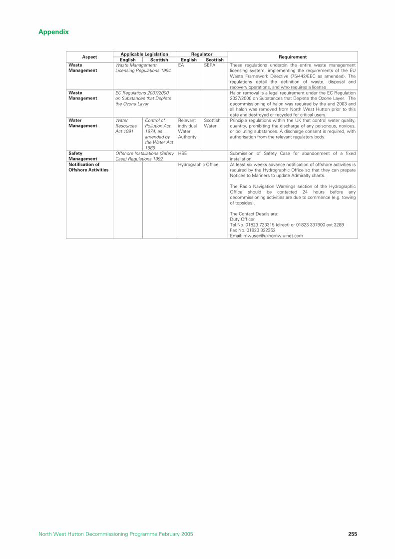
Appendix
North West Hutton Decommissioning Programme February 2005 255
Applicable Legislation Regulator Aspect
English Scottish English ScottishRequirement
Waste Management
Waste Management Licensing Regulations 1994
EA SEPA These regulations underpin the entire waste management licensing system, implementing the requirements of the EUWaste Framework Directive (75/442/EEC as amended). The regulations detail the definition of waste, disposal and recovery operations, and who requires a license
Waste Management
EC Regulations 2037/2000 on Substances that Deplete the Ozone Layer
Halon removal is a legal requirement under the EC Regulation 2037/2000 on Substances that Deplete the Ozone Layer. The decommissioning of halon was required by the end 2003 and all halon was removed from North West Hutton prior to this date and destroyed or recycled for critical users.
Water Management
Water Resources Act 1991
Control of Pollution Act 1974, as amended by the Water Act 1989
Relevant individual Water Authority
Scottish Water
Principle regulations within the UK that control water quality, quantity, prohibiting the discharge of any poisonous, noxious, or polluting substances. A discharge consent is required, with authorisation from the relevant regulatory body.
Safety Management
Offshore Installations (Safety Case) Regulations 1992
HSE Submission of Safety Case for abandonment of a fixed installation.
Notification of Offshore Activities
Hydrographic Office At least six weeks advance notification of offshore activities is required by the Hydrographic Office so that they can prepare Notices to Mariners to update Admiralty charts. The Radio Navigation Warnings section of the Hydrographic Office should be contacted 24 hours before any decommissioning activities are due to commence (e.g. towing of topsides). The Contact Details are: Duty Officer Tel No. 01823 723315 (direct) or 01823 337900 ext 3289 Fax No. 01823 322352 Email: [email protected]

Appendix
North West Hutton Decommissioning Programme February 2005256
REFERENCES
AAdams J. A. (1987), The primary ecological subdivisions of the North Sea: Some aspects of their planktoncommunities. In Bailey, R and Parish BB eds., Development in Fisheries in Scotland. Fisheries News, London165 – 181 pp.
Aker Kvaerner, TEC05 - Jacket Information Package-13th May 2003-8226-NWH-ST-004
Aker Kvaerner, TEC27 - Jacket Damage Identification & Drill Cuttings Partial Removal Study -22nd December2003-8226-NWH-ST-16
Altair Engineering, TEC25 - Investigation of Jacket Lifting and Footings Options for North West HuttonDecommissioning -25th June 2003-BPABD-29-03-R-01
Amoco (UK) Exploration Company, North West Hutton Platform, Inspection and Repair Status,September 1982.
Andrew Palmer & Associates, SAF05 - North West Hutton Pipelines Decommissioning Study HAZID -14th
August 2003-4760A–RPT-002
Andrew Palmer & Associates, SAF06 - North West Hutton Pipelines Decommissioning Study HAZID -14th
August 2003-4760A–RPT-001
BBP HSE Policy
BP HSE Management System
BP North West Hutton Field, Cessation of Production Application, Final Version 4.0, July 1999.
BP, TEC06 - Alternative Removal Methods-June 2003
BP, ECO01, 04, 06 and 06 - North West Hutton Decommissioning Project Cost Estimate Summary-14th
January 2004-
BP, ECO03 - Impact on Scrap Steel Market-2003
BP, ECO07 - North West Hutton Decommissioning Project Long Term Monitoring Requirements-27th August 2003-
BP, North West Hutton Abandonment Safety Case, Document No. NWH-ASC-001/002/003, 25th March 2004
BMT Cordah Limited, ENV01 - Environmental Impact Statement in support of the Decommissioning of theNorth West Hutton facilities -June 2004-BPX067/ES/2003
BMT Cordah Limited, ENV02 - Energy and Emissions Report for the Decommissioning of North WestHutton-2003-
BMT Cordah Limited, ENV03 - Evaluation of the distribution of the cold-water coral Lophelia pertusa on theNorth West Hutton Platform -11th March 2003-BPX54/NWH/05
BMT Cordah Limited, ENV04 - North West Hutton Cuttings Pile Modeling -31st March 2003-280000/03
BMT Cordah Limited, ENV05 - Analysis of samples collected from cuttings pile at North West Hutton -30th
June 2004-BPX45/NWH/04
BMT Cordah Limited, ENV08 - Long-Term Trends in Seabed Disturbance around the North West Huttonplatform – 2004. BPX54/NWH/04
BMT Cordah Limited, TEC13 - North West Hutton A Synopsis of Environmental Studies of the Cuttings Pileand surrounding Seabed -24th May 2004-L3/AB/26(a)/T/OAM/30.4.02/A
Brown and Root Survey (1992), North West Hutton Drill Cuttings Survey Report, Document No. M70381(0753R) 160293, Rev 1, 16th February 1993.
References
North West Hutton Decommissioning Programme February 2005 257

CCorrpro Europe Limited, TEC01 - Life assessment of Jacket Footings-19th September 2003
COWI, TEC29 - Removal of the North West Hutton Jacket – Quantitative Comparative Assessment -26th
March 2004-P-058983-A-100
Coull, K. A., Johnstone, R. and Rogers, S.I. (1998). Fisheries Sensitivity Maps in British Waters, UKOOA Ltd.
DDepartment of Trade and Industry (DTI), Oil and Gas Guidance Notes for Industry Decommissioning ofOffshore Installations and Pipelines under the Petroleum Act 1998, Published by Offshore DecommissioningUnit, Department of Trade and Industry, 21 August 2000.
Department of Trade and Industry (DTI), Well Operations and Notifications System (WONS) WellAbandonment Consents
Department of Trade and Industry (DTI), Decommissioning of Offshore Installations and Pipelines under thePetroleum Act 1998, www.og.dti.gov.uk
Det Norske Veritas (DNV), SAF07A –Independent Review of Jacket Removal HAZIDs & QRAs-24th September 2003-
Det Norske Veritas (DNV), SAF07B - Independent Review of cuttings HAZIDa and QRAs -25th September 2003-
Dredging Research Ltd., TEC11 & 12 - Technical Review of the Options of Covering, Relocating, CAD, andRecovery of Onshore Treatment of the North West Hutton Drill Cuttings Pile.-
DTZ Pieda Consulting, SOC02 - North West Hutton Decommissioning Economic Impact Report-2003
EEC Directive 79/409/EEC, 2nd April 1979, On the Conservation of the Wild Birds.
EC Directive 92/43/EEC, 21st May 1992, On the Conservation of Natural Habitats and of Wild Fauna and Flora.Last 8th July 2003.
Eric Faulds Associates Ltd, North West Hutton Topsides Piece Small Dismantling Study, April 2003.
Excalibur Engineering BV, website: www.excalibur-engineering.com
Explosive Engineering Associates, TEC07 - A Review of Jacket Footings Removal using Explosives -234r June 2003
GGlobal Maritime, TEC04B – Jacket Removal Study for Complete or Partial Removal, 4th July 2003. GM-22875-0703-1408
HHEEREMA Marine Contractors, North West Hutton, Platform Removal Feasibility Study, Document No.E/1018 (2205), Rev 2, dated 29th October 1999.
Hereema Marine Contractors Nederland B.V., SAF01A - North West Hutton Decommissioning HazardIdentification Review Assessment-2nd April 2003
Hereema Marine contractors Nederland B.V., TEC02A - North West Hutton Substructure DecommissioningComparative Assessment Detailed Removal Method -24th June 2003-G1100-RP01
HSE SPC/Enf/38 Guidance on ALARP for Offshore Division Inspectors, www.hse.gov.uk
References
North West Hutton Decommissioning Programme February 2005258
IIndependent Review Group (IRG) North West Hutton Decommissioning Project, Report of the IndependentReview Group, 26th April 2004.
JJoint Industries Project (JIP), Single Lift Concepts Summing Up, DNV |Report No. 2001 – 0553, Rev 02.
JNCC, (1999), Seabird vulnerability in UK waters: Block specific vulnerability, 1999. Joint Nature ConservationCommittee, Aberdeen
JNCC, (2002), Natura 2000 in UK Offshore Waters: Advice to Support the Implementation of the EC Habitatsand Birds Directives in UK Offshore Waters, JNCC Report 325, http://www.jncc.gov.uk
J.P. Kenny, ENV06 - Pipeline Cleanliness Assessment / Assurance -11th November 2003-02-2416-01-0-3-002
JP Kenny, TEC14-18 & ENV06 - Pipeline Decommissioning – Technical Summary Report -21st November2003-05-2416-01-G-3-011
JP Kenny, ECO05 - North West Hutton Pipelines Decommissioning Economics of Options -2003-05-2416-01-P-3-009
KKerr McGee, 2002, Hutton Field De-commissioning Programme.
LLloyd’s Register, North West Hutton Decommissioning Residual Waste Survey, Reference 0391215/R/003,February 2004.
MMonitor, website: www.monitoroil.com
NNoble Denton Europe Ltd., TEC04A - Independent Comparative Assessment of Partial Jacket Removal -4th
July 2003-A4113/NDE/MGB/1
North West Hutton Cessation of Production Application, Rev. 4, July 1999.
North West Hutton Technical Datapack, Document No. EOS-NWHD-BPA-FAC-DSB-001 Rev A, 22nd
November 1999.
OOffshore Petroleum Activities (Conservation of Habitats) Regulations, 2001
OWLET Group, North West Hutton Decommissioning Alternatives Study Report, Rev 1, 17th June 2002.
1992 OSPAR Convention, Convention for the Protection of the Marine Environment of the North-EastAtlantic, 22nd September 1992.
1998 Ministerial Meeting of the OSPAR Commission, Sintra, Portugal on 22 – 23 July 1998, OSPARDecision 98/3, Date of Adoption 1998, Sintra.
PPetroleum Act 1998
References
North West Hutton Decommissioning Programme February 2005 259
RRisk Support Risk Management Strategies, SAF01B - Quantitative Risk Assessment of Removal of theNorth West Hutton Jacket – HMC’s Procedure -15th July 2003-R205.
Risk Support Risk Management Strategies, SAF02A - Quantitative Risk Assessment of the Removal of theNorth West Hutton Jacket – Saipem’s Procedures-17th July 2003-R211
Risk Support Risk Management Strategies, SAF02C - Quantitative Risk Assessment of the Removal of theNorth West Hutton Jacket – BP Model-23rd July 2003-R-BP Case
Risk Support Risk Management Strategies, SAF03 & 04 - Quantitative Risk Assessment of Options forRecovering Drill Cuttings-18th July 2003-R213aUTONATI NUMBERING
SSasp Offshore Engineering UK, North West Hutton Decommissioning Study, Document No. 540039-02-LE-70002, Rev B, 9th March 1999.
Saipem, North West Hutton, Decommissioning Study, Supplementary Study Report, Document No. 979924-REP-1001, Rev 01, dated 15th November 1999.
Saipem UK, TEC02B & SAF01A - North West Hutton Decommissioning Study Year 2003 Refreshment StudyReport-2003-973000-NWH 2003-001
Seaway Heavy Lifting, Removal and Transportation Methodology for North West Hutton Topsides and JacketUpper Sections Study, Document No. SHL.47.450.GM-011, Rev C, 1st November 1999.
Scan Tech UK, TEC10 - North West Hutton Decommissioning Drill Cuttings Transfer Method Study -21st May2003-J-1090
SFF Services Ltd., SOC01 - BP North West Hutton Decommissioning Fisheries Overview-2003-
Statutory Instrument 1992 No. 2885, The Offshore Installations (Safety Case) Regulations 1992.
Statutory Instrument 1994 No. 2716, The Conservation (Natural Habitats etc.) Regulations 1994
Stolt Offshore, TEC28A - Removal of the North West Hutton Platform – Overview of the Subsea OperationsRev 1.0 -14th November 2003-MEC-066-040
Stone, C.J., (2001), Cetacean observations during seismic surveys in 1999, JNCC Report. No. 316http://jncc.gov.uk
Subsea 7, TEC03A - Inspection Report containing information from Video Logs and Workscope -14th January2004-AB-R-RP-01208
Subsea 7, TEC03B - Grout Densitometer Removal Proposal -8th January 2004-AB-T-pp-00109
TTask Force Industry, TEC09 - Study sponsored by the Decommissioning Technology Forum JacketRemoval-July 2003
Technip-Coflexip, TEC26 - North West Hutton Drilling Template & Mud Line Brace Decommissioning –Drilling Template Removal & Brace Cutting Study Report-4th July 2003-
Technip-Coflexip, TEC28B - North West Hutton Decommissioning Leg Cutting Review – Jacket Leg CuttingStudy -5th December 2003-
Twachtman Snyder & Byrd, Inc, Alternative Uses for East of Shetland Basin Facilities, Rev 1, August 2002
References
North West Hutton Decommissioning Programme February 2005260

UUKDMAP,(1998), United Kingdom Digital Marine Atlas – An atlas of the seas around the British Isles. Softwarethird edition compiled by British Oceanographic Data Centre, Birkenhead.
UKOOA Drill Cutting Initiative, Final Report, February 2002.
UKOOA, Drill Cuttings Initiative Food Chain Effects Literature Review, Report to UKOOA, March 2003, HarleyAnderson Ltd, Battelle Memorial Institute, University of Wales – Bangor, Continental Shelf Associates Inc.(UKOOA Drill Cuttings JIP, Phase 2 follow up reports)
WWood Group Engineering (WGE), North West Hutton, Class III Scope Definition for Preparation of Topsidesfor Removal, WGE Doc No. 37E034F0003/SE/RE/001, October 1999.
Wood Group Engineering Ltd, North West Hutton Platform De-commissioning Study, Document No.37E034F0032/IE/SU/001, Rev B, 12/12/01.
Wood Group / Rigblast, North West Hutton Decommissioning Project, Front End Engineering Design(Engineering Down & Cleaning), Document No. 37NWH-E0340047-Z-RE-0001-000, October 2002.
Wood Group / Rigblast, North West Hutton Decommissioning Project, Module Process & Utility SeparationFEED, Document No. 37NWH-E034F0047-Z-RE-0006, dated October 2003.
WS Atkins Oil and Gas, North West Hutton, Appurtenance Arrangement (Sheet 4 of 5), Drawing No. NWH-APD4, January 1999.
WS Atkins, North West Hutton Jacket Decommissioning Study, Document No. CL4521-ER-01, Issue 01,September 2002.
References
North West Hutton Decommissioning Programme February 2005 261
Confidentiality Statement
The references, reports and studies cited in this documentare available for review on request. Some contain
commercially and technically sensitive information andwill only be made available in an edited form.

References
North West Hutton Decommissioning Programme February 2005262