Embed Size (px)
Citation preview

NORTH OF ENGLAND INSTITUTE OF MINING AND MECHANICAL ENGINEERS.
TRANSACTIONS.
VOL. XXIX.
1879-80.
NEWCASTLE-UPON-TYNE: A. REID, PRINTING COURT BUILDINGS, AKENSIDE HILL.
1880
[iii]
ERRATA.
The translation of the Report mentioned on page 112 was placed at the disposition of the Institute
by Mr. James Ashworth.
On page 159, par. 3, line 9, for "which have been translated by Mr. C. G. Jackson," read " which has
been translated by the writer with the co-operation of Mr. C. G. Jackson."
CONTENTS OF VOL. XXIX.
PAGE.
Report or Council ............ v.
Finance Report.................. ix.
Account of Subscriptions ... xii.
Treasurer's Account ......... xiv.
General Account ............... xvi.
Patrons.............................. xvii.
Honorary and Life Members xviii.
Officers ........................... xix.
Original Members ............ xx.
PAGE.
Ordinary Members ............ xxxv.
Associate Members ............ xxxv.
Students ........................... xxxvii.
Subscribing Collieries ...... xl.
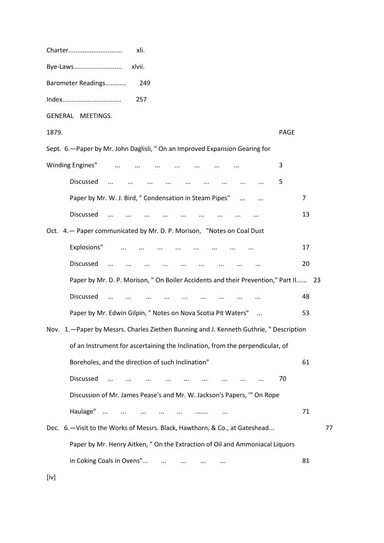
Charter.............................. xli.
Bye-Laws........................... xlvii.
Barometer Readings............ 249
Index................................. 257
GENERAL MEETINGS.
1879. PAGE
Sept. 6.—Paper by Mr. John Daglisli, " On an Improved Expansion Gearing for
Winding Engines" ... ... ... ... ... ... ... 3
Discussed ... ... ... ... ... ... ... ... ... 5
Paper by Mr. W. J. Bird, " Condensation in Steam Pipes" ... ... 7
Discussed ... ... ... ... ... ... ... ... ... 13
Oct. 4.— Paper communicated by Mr. D. P. Morison, "Notes on Coal Dust
Explosions" ... ... ... ... ... ... ... ... 17
Discussed ... ... ... ... ... ... ... ... ... 20
Paper by Mr. D. P. Morison, " On Boiler Accidents and their Prevention," Part II...... 23
Discussed ... ... ... ... ... ... ... ... ... 48
Paper by Mr. Edwin Gilpin, " Notes on Nova Scotia Pit Waters" ... 53
Nov. 1.—Paper by Messrs. Charles Ziethen Bunning and J. Kenneth Guthrie, " Description
of an Instrument for ascertaining the Inclination, from the perpendicular, of
Boreholes, and the direction of such Inclination" 61
Discussed ... ... ... ... ... ... ... ... ... 70
Discussion of Mr. James Pease's and Mr. W. Jackson's Papers, '" On Rope
Haulage" ... ... ... ... ... ....... ... 71
Dec. 6.—Visit to the Works of Messrs. Black, Hawthorn, & Co., at Gateshead... 77
Paper by Mr. Henry Aitken, " On the Extraction of Oil and Ammoniacal Liquors
in Coking Coals in Ovens"... ... ... ... ... 81
[iv]
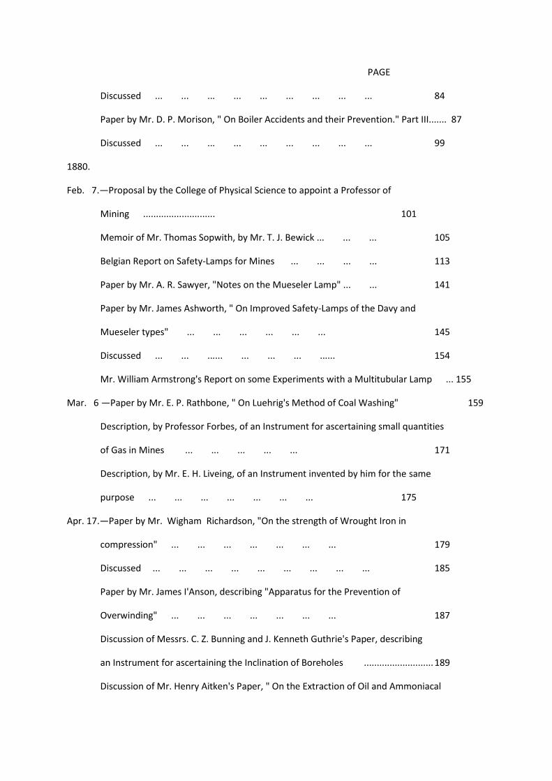
PAGE
Discussed ... ... ... ... ... ... ... ... ... 84
Paper by Mr. D. P. Morison, " On Boiler Accidents and their Prevention." Part III....... 87
Discussed ... ... ... ... ... ... ... ... ... 99
1880.
Feb. 7.—Proposal by the College of Physical Science to appoint a Professor of
Mining ............................ 101
Memoir of Mr. Thomas Sopwith, by Mr. T. J. Bewick ... ... ... 105
Belgian Report on Safety-Lamps for Mines ... ... ... ... 113
Paper by Mr. A. R. Sawyer, "Notes on the Mueseler Lamp" ... ... 141
Paper by Mr. James Ashworth, " On Improved Safety-Lamps of the Davy and
Mueseler types" ... ... ... ... ... ... 145
Discussed ... ... ...... ... ... ... ...... 154
Mr. William Armstrong's Report on some Experiments with a Multitubular Lamp ... 155
Mar. 6 —Paper by Mr. E. P. Rathbone, " On Luehrig's Method of Coal Washing" 159
Description, by Professor Forbes, of an Instrument for ascertaining small quantities
of Gas in Mines ... ... ... ... ... 171
Description, by Mr. E. H. Liveing, of an Instrument invented by him for the same
purpose ... ... ... ... ... ... ... 175
Apr. 17.—Paper by Mr. Wigham Richardson, "On the strength of Wrought Iron in
compression" ... ... ... ... ... ... ... 179
Discussed ... ... ... ... ... ... ... ... ... 185
Paper by Mr. James I'Anson, describing "Apparatus for the Prevention of
Overwinding" ... ... ... ... ... ... ... 187
Discussion of Messrs. C. Z. Bunning and J. Kenneth Guthrie's Paper, describing
an Instrument for ascertaining the Inclination of Boreholes ........................... 189
Discussion of Mr. Henry Aitken's Paper, " On the Extraction of Oil and Ammoniacal

Liquors in Coking Coal in Ovens" ... ... ... 192
May 1.—Paper by Mr. William Logan, " On Safety-Hooks" ... ... ... 201
Discussed ... ... ... ... ... ... ... ... ... 215
Paper by Mr. Thomas Heppell, " On Cranston's Pneumatic Rock-Drill" 221
June 19.—Discussion of Mr. James I'Anson's Paper, " On Apparatus for the Prevention of
Overwinding" ... ... ... ... ... ... 227
Discussion of Mr. William Logan's Paper, "On Safety-Hooks" ... 229
Paper communicated by Mr. Robert Miller, " On Jefferson's Automatic, Free-falling,
Hydraulic Boring Apparatus" ... ... ... ... 235
Aug. 7.—Paper by Mr. Henry Hall, " On Rapid Sinking" ......... 243
Discussed ... ... ... ... ... ... ... ... ... 246
[v]
Report.
Notwithstanding that during the latter part of the year 1879 there seemed to be some prospect of
renewed prosperity in the coal trade, it is much to be regretted that the hopes then entertained
were speedily dissipated. It is true that prices have since ruled a fraction higher in the North of
England, but even this small increase has not extended into other districts. While this continued
depression of the trade, which more particularly interests the Members of the Institute, continues, it
is not to be wondered at that the Report, which it is the duty of the Council to present to the
Members at their Annual Meeting, should be more or less of an unsatisfactory nature; and although
they can safely affirm that the position of the Institute is very much more satisfactory than from the
nature of things might be expected, yet still, when a decrease in the number of Members, coupled
with a decrease of income, has to be admitted for almost the first time in the annals of an Institution
that has for so many years steadily increased, the result cannot be considered as altogether
satisfactory. The decrease, however, is small, as will be seen by the report of the Finance
Committee, and does not in any way affect the financial position of the Institute, for there has been
an actual increase of income over expenditure of £323 16s. 6d. But the Council would nevertheless
earnestly appeal to all who have the welfare of the Institute at heart to endeavour by all means in
their power to extend its influence by introducing members and assisting in the work it was
established to perform, and otherwise extend its prestige and standing.
At no time indeed has it been more necessary for gentlemen connected with mining operations to
carefully weigh and consider all circumstances tending to cause danger in the working of minerals,
and to endeavour by every means in their power to lessen their fatal influences. That accidents are
unfortunately in many cases unavoidable is but too true, but that much can be done to lessen their
number and diminish their importance is not to be doubted, and nothing can be more conducive to
this result than extending our researches into the nature of the circumstances which produce them,
and so endeavour to reduce them as much as possible to well ascertained rules.
[vi]
Although not the chief cause of loss of life, the pressure of gas in coal workings is unquestionably the
most alarming from the number of victims it immolates at a time.
To arrive at a more conclusive knowledge of the nature and extent of the phenomena connected
with the pressure of gas in coal, our late President, Mr. Lindsay Wood, has been induced to make a
series of experiments at some of his collieries, the result of which has been made known in a paper
communicated to the members, and which will be published in the next volume.
The Council think that this is the most valuable addition that has been made for some years to our
knowledge of the extraordinary power coal possesses of occluding gas at extreme pressures, and
there is no doubt that when the records of these experiments have been carefully studied that they
will point the way to more effective means of keeping the workings clear. The experiments that have
been made by the Ventilators Committee with a view of ascertaining the relative merits of the
various machines employed in producing an artificial current of air in mines by mechanical means
may be considered to be of extreme importance, as tending to lessen loss of life from the presence
of gas. The results of the experiments will soon be before the public and will afford much valuable
information.
With regard to the proceedings generally it may be said that they are above the usual average. Mr.
D. P. Morison has summarised all that can be said on the important subject of " Boiler Accidents and
their Prevention," and contributed a mass of valuable statistics relating thereto.
The subject of Safety-hooks has also been taken up by Mr. Logan, and most of the inventions for
increasing the safety of life in the shafts of pits have been minutely described and commented upon.
Safety-lamps have also been treated in the same way by Mr. A. B. Sawyer and Mr. James Ashworth,
the latter gentleman contributing a valuable translation of the Report of the Government
Commission in Belgium.
These papers all refer, more or less, to the preservation of life, but economic matters of
considerable importance have also been the subject of several interesting contributions.
That by Mr. Henry Aitken, " On the Extraction of Oil and Ammoniacal Liquors from Coking Coal in
Ovens," points out a mode by which products hitherto lost may be made of value; and one by Mr.
Rathbone, " On a Method of Washing Coal in Germany," shows how the economical value of inferior
coal may be considerably increased.
[vii]
The papers by Mr. John Daglish, " On an Improved Expansion Gear for Winding Engines;" by Mr.
Wigham Richardson, "On the Strength of Wrought Iron in Compression;" by Mr. W. J. Bird, " On
Condensation in Steam Pipes;" and by Mr. D. P. Morison, " On Coal-dust Explosions," also add
considerably to the value of the Transactions.

There have been no excursions during the year, but a very interesting visit was made to the
establishment of Messrs. Black, Hawthorn, and Co., at Gateshead, who were kind enough to exhibit
the many important engineering works in course of construction by them, and also their tramway
locomotive, under steam.
[viii]
blank page
[ix]
Finance Report
The Finance Committee have to report that the receipts from all sources for the past year have been
£1,942 11s. 3d., being £196 0s. 7d. less than last year, when they amounted to £2,138 11s. 10d. This
falling off has been chiefly due to the difference in the sales of publications, which amounted last
year to £166 13s. 9d., and this year only to £53 7s. 9d., making a difference of £113 6s.
The Members' subscriptions amounted to £1,626 10s. as against £1,709 10s., showing a decrease of
£83.
The expenditure has been £1,618 14s. 9d. as against £2,080 4s. 10d. last year, the excess of income
over expenditure being £323 16s. 6d.
The Institute continues to hold 134 shares in the Institute and Coal Trade Chambers Company,
Limited, to the amount of £2,680.
[x]
blank page
[xi]
ADVERTISEMENT.
The Institute is not, as a body, responsible for the facts and opinions advanced in the Papers read,
and in the Abstracts of the Conversations which occurred at the Meetings during the Session.
[xii
THE TREASURER IN ACCOUNT WITH SUBSCRIPTIONS, 1879-80.
[financial tables]
[xiii]
[financial tables]
[xiv]
TREASURER IN ACCOUNT WITH THE NORTH OF ENGLAND INSTITUTE OF MINING AND
MECHANICAL ENGINEERS.
[financial tables]
[xv]
[financial tables]
[xvi]
[financial tables]
[xvii]
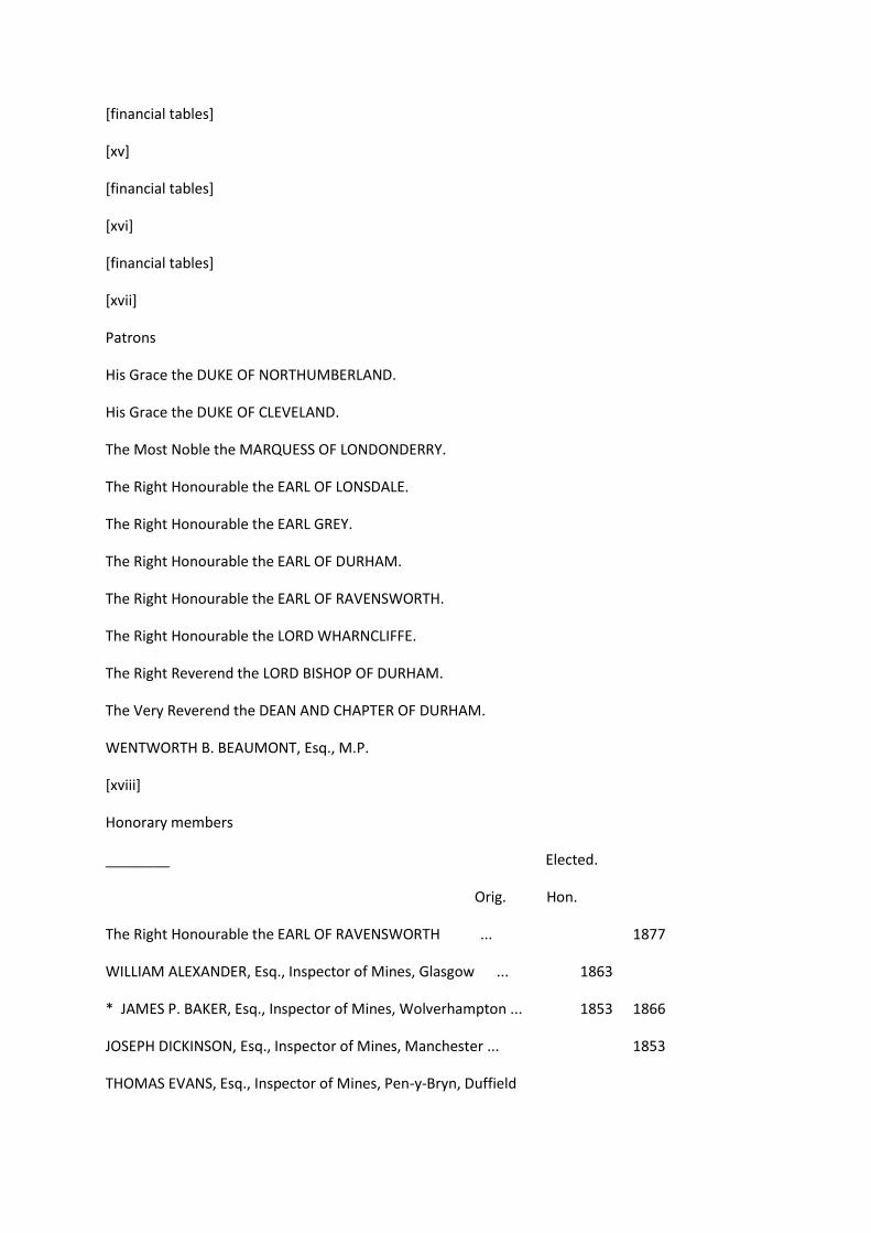
Patrons
His Grace the DUKE OF NORTHUMBERLAND.
His Grace the DUKE OF CLEVELAND.
The Most Noble the MARQUESS OF LONDONDERRY.
The Right Honourable the EARL OF LONSDALE.
The Right Honourable the EARL GREY.
The Right Honourable the EARL OF DURHAM.
The Right Honourable the EARL OF RAVENSWORTH.
The Right Honourable the LORD WHARNCLIFFE.
The Right Reverend the LORD BISHOP OF DURHAM.
The Very Reverend the DEAN AND CHAPTER OF DURHAM.
WENTWORTH B. BEAUMONT, Esq., M.P.
[xviii]
Honorary members
________ Elected.
Orig. Hon.
The Right Honourable the EARL OF RAVENSWORTH ... 1877
WILLIAM ALEXANDER, Esq., Inspector of Mines, Glasgow ... 1863
* JAMES P. BAKER, Esq., Inspector of Mines, Wolverhampton ... 1853 1866
JOSEPH DICKINSON, Esq., Inspector of Mines, Manchester ... 1853
THOMAS EVANS, Esq., Inspector of Mines, Pen-y-Bryn, Duffield
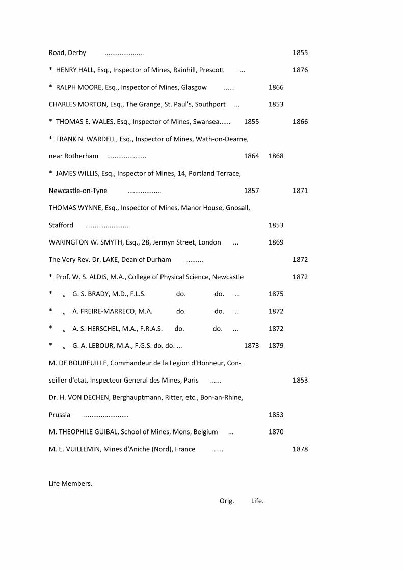
Road, Derby ..................... 1855
* HENRY HALL, Esq., Inspector of Mines, Rainhill, Prescott ... 1876
* RALPH MOORE, Esq., Inspector of Mines, Glasgow ...... 1866
CHARLES MORTON, Esq., The Grange, St. Paul's, Southport ... 1853
* THOMAS E. WALES, Esq., Inspector of Mines, Swansea...... 1855 1866
* FRANK N. WARDELL, Esq., Inspector of Mines, Wath-on-Dearne,
near Rotherham ..................... 1864 1868
* JAMES WILLIS, Esq., Inspector of Mines, 14, Portland Terrace,
Newcastle-on-Tyne .................. 1857 1871
THOMAS WYNNE, Esq., Inspector of Mines, Manor House, Gnosall,
Stafford ........................ 1853
WARINGTON W. SMYTH, Esq., 28, Jermyn Street, London ... 1869
The Very Rev. Dr. LAKE, Dean of Durham ......... 1872
* Prof. W. S. ALDIS, M.A., College of Physical Science, Newcastle 1872
* „ G. S. BRADY, M.D., F.L.S. do. do. ... 1875
* „ A. FREIRE-MARRECO, M.A. do. do. ... 1872
* „ A. S. HERSCHEL, M.A., F.R.A.S. do. do. ... 1872
* „ G. A. LEBOUR, M.A., F.G.S. do. do. ... 1873 1879
M. DE BOUREUILLE, Commandeur de la Legion d'Honneur, Con-
seiller d'etat, Inspecteur General des Mines, Paris ...... 1853
Dr. H. VON DECHEN, Berghauptmann, Ritter, etc., Bon-an-Rhine,
Prussia ........................ 1853
M. THEOPHILE GUIBAL, School of Mines, Mons, Belgium ... 1870
M. E. VUILLEMIN, Mines d'Aniche (Nord), France ...... 1878
Life Members.
Orig. Life.

C. W. BARTHOLOMEW, Esq., Blakesley Hall, near Towcester ... 1875
DAVID BURNS, Esq., C.E., Brookside, Haltwhistle......... 1877
E. B. COXE, Esq., Drifton, Jeddo, P.O., Luzerne Co., Penns., U.S. ... 1873 1874
ERNEST HAGUE, Esq., Castle Dyke, Sheffield ......... 1872 1876
G. C. HEWITT, Esq., Coalpit Heath Colliery, near Bristol...... 1871 1879
HENRY LAPORTE, Esq., M.E., 80, Rue Royale, Brussels...... 1877
NATHAN MILLER, Kurhurballee Collieries, East Indian Railway,
Chord Line, Bengal .................. 1878
H. J. MORTON, Esq., 4, Royal Crescent, Scarborough ...... 1856 1861
RUDOLPH NASSE, Konigl Bergwerks Director, Louisenthal,
Saarbruecken ..................... 1869 1880
W. A. POTTER, Esq., Cramlington House, Northumberland ... 1853 1874
R. CLIFFORD SMITH, Esq., Parkfield, Swinton, Manchester ... 1874
* Honorary Members during term of office only.
[xix]
OFFICERS, 1880-81.
President
G. C. GREENWELL, Esq., F.G.S., Tynemouth.
Vice-Presidents
CUTHBERT BERKLEY, Esq., Marley Hill, Gateshead.
T. J. BEWICK, Esq., Haydon Bridge, Northumberland.
WM. COCHRANE, Esq., St. John's Chambers, Grainger Street West,
Newcastle-on-Tyne.
JOHN MARLEY, Esq., Mining Offices, Darlington.
J. B. SIMPSON, Esq., Hedgefield House, Blaydon-on-Tyne.
A. L. STEAVENSON, Esq., Durham.
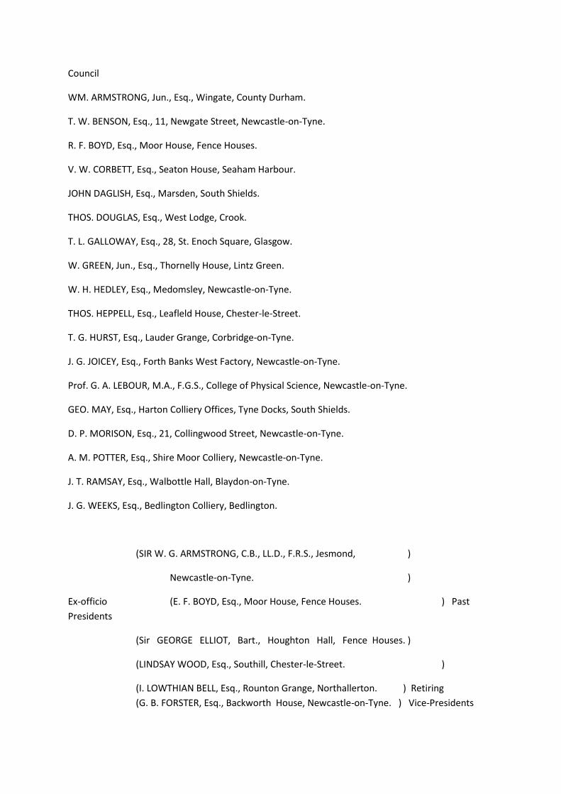
Council
WM. ARMSTRONG, Jun., Esq., Wingate, County Durham.
T. W. BENSON, Esq., 11, Newgate Street, Newcastle-on-Tyne.
R. F. BOYD, Esq., Moor House, Fence Houses.
V. W. CORBETT, Esq., Seaton House, Seaham Harbour.
JOHN DAGLISH, Esq., Marsden, South Shields.
THOS. DOUGLAS, Esq., West Lodge, Crook.
T. L. GALLOWAY, Esq., 28, St. Enoch Square, Glasgow.
W. GREEN, Jun., Esq., Thornelly House, Lintz Green.
W. H. HEDLEY, Esq., Medomsley, Newcastle-on-Tyne.
THOS. HEPPELL, Esq., Leafleld House, Chester-le-Street.
T. G. HURST, Esq., Lauder Grange, Corbridge-on-Tyne.
J. G. JOICEY, Esq., Forth Banks West Factory, Newcastle-on-Tyne.
Prof. G. A. LEBOUR, M.A., F.G.S., College of Physical Science, Newcastle-on-Tyne.
GEO. MAY, Esq., Harton Colliery Offices, Tyne Docks, South Shields.
D. P. MORISON, Esq., 21, Collingwood Street, Newcastle-on-Tyne.
A. M. POTTER, Esq., Shire Moor Colliery, Newcastle-on-Tyne.
J. T. RAMSAY, Esq., Walbottle Hall, Blaydon-on-Tyne.
J. G. WEEKS, Esq., Bedlington Colliery, Bedlington.
(SIR W. G. ARMSTRONG, C.B., LL.D., F.R.S., Jesmond, )
Newcastle-on-Tyne. )
Ex-officio (E. F. BOYD, Esq., Moor House, Fence Houses. ) Past
Presidents
(Sir GEORGE ELLIOT, Bart., Houghton Hall, Fence Houses. )
(LINDSAY WOOD, Esq., Southill, Chester-le-Street. )
(I. LOWTHIAN BELL, Esq., Rounton Grange, Northallerton. ) Retiring
(G. B. FORSTER, Esq., Backworth House, Newcastle-on-Tyne. ) Vice-Presidents

Secretary and Treasurer
THEO. WOOD BUNNING Neville Hall, Newcastle-on-Tyne
[xx]
List of Members
AUGUST, 1880.
Original Members.
Marked (*) are Life Members. Elected.
1 Adams, G. F., Guild Hall Chambers, Cardiff............ Dec. 6,1873
2 Adams, W., Cambridge House, Park Place, Cardiff ......... 1854
3 Adamson, Daniel, Engineering Works, Dukinfield, near Manchester Aug. 7, 1875
4 Addy, W. F., Dronfield, near Sheffield............... May 6,1876
5 Aitkin, Henry, Falkirk, N.B. ... ............... Mar. 2,1865
6 Allison, T., Belmont Mines, Guisbro'............... Feb. 1,1868
7 Anderson, C. W., Sea View, South Shields ............ Aug. 21, 1852
8 Anderson, William, Rainton Colliery, Fence Houses ...... Aug. 21, 1852
9 Andrews, Hugh, Felton Park, Felton, Northumberland ...... Oct. 5,1872
10 Appleby, C. E., Charing Cross Chambers, Duke Street, Adelphi,
London, W.C......................... Aug. 1,1861
11 Archer, T., Dunston Engine Works, Gateshead ......... July 2, 1872
12 Armstrong, Sir W. G., C.B., L.L.D., F.R.S., Jesmond, Newcastle-
upon-Tyne ...... (Past President, Member of Council) May 3, 1866
13 Armstrong, Wm., Sen., Pelaw House, Chester-le-Street ...... Aug. 21, 1852
14 Armstrong, W., Junior, Wingate, Co. Durham (Member of Council) April 7, 1867
15 Armstrong, W. L., Leighs Wood Colliery Co. Ld., Aldridge, nr. Walsall Mar. 3, 1864
16 Arthur, David, M. E., Accrington. near Manchester ...... Aug. 4, 1877
17 Ashworth, James, 56, Upper Duke Street, Southport ...... Feb. 5,1876
18 Ashworth, John, Bryn Celyn, Llanferis, Mold ......... Sept. 2, 1876

19 Asquith, T. W., Seaton Delaval Colliery, Northumberland...... Feb. 2, 1867
20 Atkinson, J. B., Ridley Mill, Stocksfield-on-Tyne ......... Mar. 5, 1870
21 Atkinson, W. N., Shincliffe Hall, Durham ............June 6,1868
22 Aubrey, R. C., Wigan Coal & Iron Co. Ld., Standish, near Wigan ... Feb. 5, 1870
23 Austine, John, Cadzow Coal Co., Glasgow ............ Nov. 4,1876
24 Aynsley, Wm., Birtley, Chester-le-Street ............ Mar. 3, 1873
25 Bagley, Chas. John, Tees Bridge Iron Co., Stockton ...... June 5, 1875
26 Bailes, George, Murton Colliery, Sunderland ......... Feb. 3,1877
27 Bailes, John, Wingate Colliery, Ferryhill ............ Sept. 5,1868
28 Bailes, T., Junior, 41, Lovaine Place, Newcastle-on-Tyne ...... Oct. 7,1858
29 Bailes, W., Murton Colliery, Sunderland ............ April 7,1877
30 Bailey, G., St. John's Colliery, Wakefield ............ June 5,1869
31 Bailey, Samuel, Perry Barr, Birmingham ............ June 2, 1859
[xxi]
ELECTED.
32 Bain, R. Donald, Newport, Monmouthshire............ Mar. 3,1873
33 Bainbridge, E., Nunnery Colliery Offices, Sheffield......... Dec. 3,1863
34 Banks, Thomas, Leigh, near Manchester ............ Aug. 4, 1877
35 Barclay, A., Caledonia Foundry, Kilmarnock ... ... ... Dec. 6,1866
36 Barkus, Wm., 1, St. Nicholas' Buildings, Newcastle-on-Tyne ... Aug. 21, 1852
37 Barnes, T., Seaton Delaval Office, Quay, Newcastle-on-Tyne ... Oct. 7,1871
38 Barrat, A. J., Ruabon Coal Co., Ruabon ............ Sept. 11, 1875
39 Bartholomew, C, Castle Hill House, Ealing, London, W....... Aug. 5,1853
40*Bartholomew, C. W., Blakesley Hall, near Towcester ...... Dec. 4, 1875
41 Bassett, A., Tredegar Mineral Estate Office, Cardiff......... 1854
42 Bates, Matthew, Bews Hill, Blaydon-on-Tyne ......... Mar. 3,1873
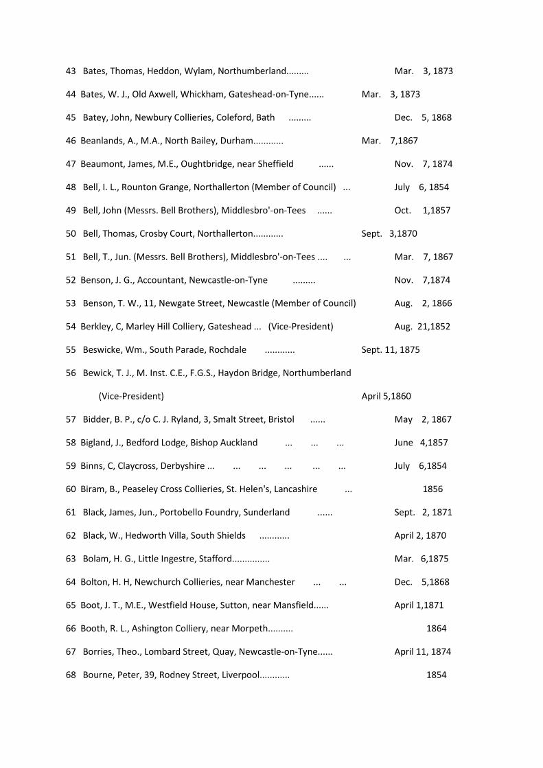
43 Bates, Thomas, Heddon, Wylam, Northumberland......... Mar. 3, 1873
44 Bates, W. J., Old Axwell, Whickham, Gateshead-on-Tyne...... Mar. 3, 1873
45 Batey, John, Newbury Collieries, Coleford, Bath ......... Dec. 5, 1868
46 Beanlands, A., M.A., North Bailey, Durham............ Mar. 7,1867
47 Beaumont, James, M.E., Oughtbridge, near Sheffield ...... Nov. 7, 1874
48 Bell, I. L., Rounton Grange, Northallerton (Member of Council) ... July 6, 1854
49 Bell, John (Messrs. Bell Brothers), Middlesbro'-on-Tees ...... Oct. 1,1857
50 Bell, Thomas, Crosby Court, Northallerton............ Sept. 3,1870
51 Bell, T., Jun. (Messrs. Bell Brothers), Middlesbro'-on-Tees .... ... Mar. 7, 1867
52 Benson, J. G., Accountant, Newcastle-on-Tyne ......... Nov. 7,1874
53 Benson, T. W., 11, Newgate Street, Newcastle (Member of Council) Aug. 2, 1866
54 Berkley, C, Marley Hill Colliery, Gateshead ... (Vice-President) Aug. 21,1852
55 Beswicke, Wm., South Parade, Rochdale ............ Sept. 11, 1875
56 Bewick, T. J., M. Inst. C.E., F.G.S., Haydon Bridge, Northumberland
(Vice-President) April 5,1860
57 Bidder, B. P., c/o C. J. Ryland, 3, Smalt Street, Bristol ...... May 2, 1867
58 Bigland, J., Bedford Lodge, Bishop Auckland ... ... ... June 4,1857
59 Binns, C, Claycross, Derbyshire ... ... ... ... ... ... July 6,1854
60 Biram, B., Peaseley Cross Collieries, St. Helen's, Lancashire ... 1856
61 Black, James, Jun., Portobello Foundry, Sunderland ...... Sept. 2, 1871
62 Black, W., Hedworth Villa, South Shields ............ April 2, 1870
63 Bolam, H. G., Little Ingestre, Stafford............... Mar. 6,1875
64 Bolton, H. H, Newchurch Collieries, near Manchester ... ... Dec. 5,1868
65 Boot, J. T., M.E., Westfield House, Sutton, near Mansfield...... April 1,1871
66 Booth, R. L., Ashington Colliery, near Morpeth.......... 1864
67 Borries, Theo., Lombard Street, Quay, Newcastle-on-Tyne...... April 11, 1874
68 Bourne, Peter, 39, Rodney Street, Liverpool............ 1854
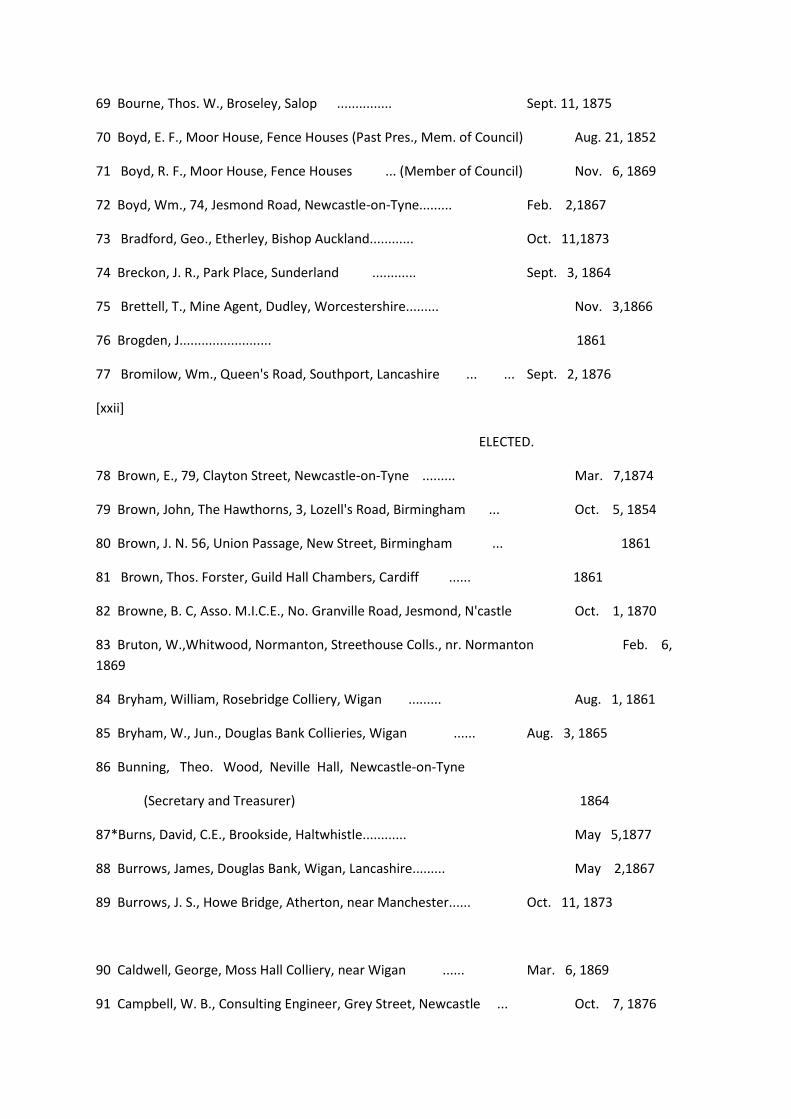
69 Bourne, Thos. W., Broseley, Salop ............... Sept. 11, 1875
70 Boyd, E. F., Moor House, Fence Houses (Past Pres., Mem. of Council) Aug. 21, 1852
71 Boyd, R. F., Moor House, Fence Houses ... (Member of Council) Nov. 6, 1869
72 Boyd, Wm., 74, Jesmond Road, Newcastle-on-Tyne......... Feb. 2,1867
73 Bradford, Geo., Etherley, Bishop Auckland............ Oct. 11,1873
74 Breckon, J. R., Park Place, Sunderland ............ Sept. 3, 1864
75 Brettell, T., Mine Agent, Dudley, Worcestershire......... Nov. 3,1866
76 Brogden, J......................... 1861
77 Bromilow, Wm., Queen's Road, Southport, Lancashire ... ... Sept. 2, 1876
[xxii]
ELECTED.
78 Brown, E., 79, Clayton Street, Newcastle-on-Tyne ......... Mar. 7,1874
79 Brown, John, The Hawthorns, 3, Lozell's Road, Birmingham ... Oct. 5, 1854
80 Brown, J. N. 56, Union Passage, New Street, Birmingham ... 1861
81 Brown, Thos. Forster, Guild Hall Chambers, Cardiff ...... 1861
82 Browne, B. C, Asso. M.I.C.E., No. Granville Road, Jesmond, N'castle Oct. 1, 1870
83 Bruton, W.,Whitwood, Normanton, Streethouse Colls., nr. Normanton Feb. 6,
1869
84 Bryham, William, Rosebridge Colliery, Wigan ......... Aug. 1, 1861
85 Bryham, W., Jun., Douglas Bank Collieries, Wigan ...... Aug. 3, 1865
86 Bunning, Theo. Wood, Neville Hall, Newcastle-on-Tyne
(Secretary and Treasurer) 1864
87*Burns, David, C.E., Brookside, Haltwhistle............ May 5,1877
88 Burrows, James, Douglas Bank, Wigan, Lancashire......... May 2,1867
89 Burrows, J. S., Howe Bridge, Atherton, near Manchester...... Oct. 11, 1873
90 Caldwell, George, Moss Hall Colliery, near Wigan ...... Mar. 6, 1869
91 Campbell, W. B., Consulting Engineer, Grey Street, Newcastle ... Oct. 7, 1876
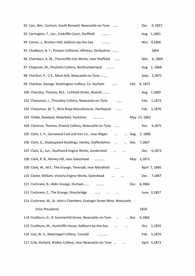
92 Carr, Wm. Cochran, South Benwell, Newcastle-on-Tyne ...... Dec. 3, 1857
93 Carrington, T., Jun., Endcliffe Court, Sheffield ......... Aug. 1,1861
94 Catron, J., Brotton Hall, Saltburn-by-the-Sea ......... Nov. 3,1866
95 Chadborn, B. T., Pinxton Collieries, Alfreton, Derbyshire ...... 1864
96 Chambers, A. M., Thorncliffe Iron Works, near Sheffield ...... Mar. 6, 1869
97 Chapman, M., Plashetts Colliery, Northumberland ......... Aug. 1, 1868
98 Charlton, P., C.E., Moot Hall, Newcastle-on-Tyne......... Sept. 2,1871
99 Charlton, George, Washington Colliery, Co. Durham ...... Feb. 6, 1875
100 Checkley, Thomas, M.E., Lichfield Street, Walsall......... Aug. 7,1869
101 Cheesman, I., Throckley Colliery, Newcastle-on-Tyne ...... Feb. 1,1873
102 Cheesman, W. T., Wire Rope Manufacturer, Hartlepool ...... Feb. 5,1876
103 Childe, Rowland, Wakefield, Yorkshire ............ May 15, 1862
104 Clarence, Thomas, Elswick Colliery, Newcastle-on-Tyne ...... Dec. 4,1875
105 Clark, C. P., Garswood Coal and Iron Co., near Wigan ... ... Aug. 2, 1866
106 Clark, G., Shakespeare Buildings, Hanley, Staffordshire ... ... Dec. 7,1867
107 Clark, G., Jun., Southwick Engine Works, Sunderland ... ... Dec. 6,1873
108 Clark, R. B., Marley Hill, near Gateshead ............ May 3,1873
109 Clark, W., M.E., The Grange, Teversall, near Mansfield ...... April 7, 1866
110 Clarke, William, Victoria Engine Works, Gateshead ... ... Dec. 7,1867
111 Cochrane, B., Aldin Grange, Durham...... ......... Dec. 6,1866
112 Cochrane, C., The Grange, Stourbridge ...... ... ... June 3,1857
113 Cochrane, W., St. John's Chambers, Grainger Street West, Newcastle
(Vice-President) 1859
114 Cockburn, G., 8, Summerhill Grove, Newcastle-on-Tyne ... ... Dec. 6,1866
115 Cockburn, W., Huntcliffe House, Saltburn-by-the-Sea ... ... Oct. 1,1859
116 Coe, W. S., Newchapel Colliery, Tunstall ............ Feb. 5,1876
117 Cole, Richard, Walker Colliery, near Newcastle-on-Tyne ... ... April 5,1873
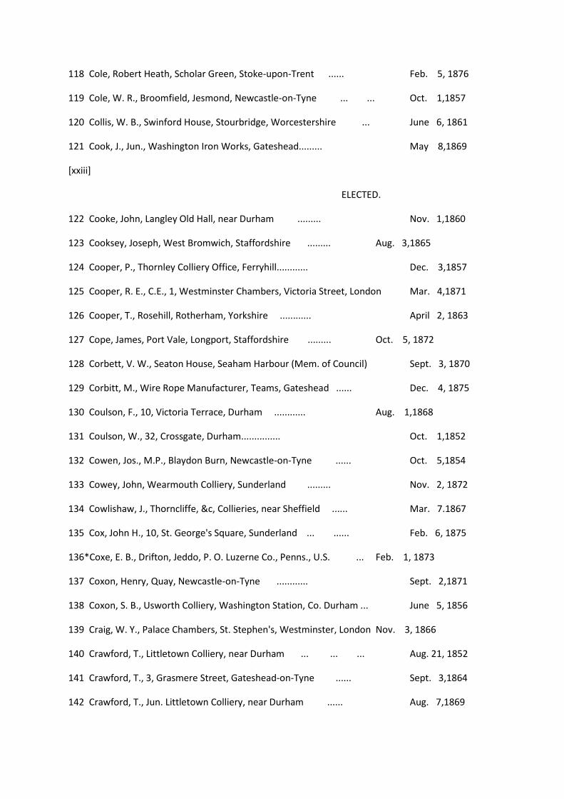
118 Cole, Robert Heath, Scholar Green, Stoke-upon-Trent ...... Feb. 5, 1876
119 Cole, W. R., Broomfield, Jesmond, Newcastle-on-Tyne ... ... Oct. 1,1857
120 Collis, W. B., Swinford House, Stourbridge, Worcestershire ... June 6, 1861
121 Cook, J., Jun., Washington Iron Works, Gateshead......... May 8,1869
[xxiii]
ELECTED.
122 Cooke, John, Langley Old Hall, near Durham ......... Nov. 1,1860
123 Cooksey, Joseph, West Bromwich, Staffordshire ......... Aug. 3,1865
124 Cooper, P., Thornley Colliery Office, Ferryhill............ Dec. 3,1857
125 Cooper, R. E., C.E., 1, Westminster Chambers, Victoria Street, London Mar. 4,1871
126 Cooper, T., Rosehill, Rotherham, Yorkshire ............ April 2, 1863
127 Cope, James, Port Vale, Longport, Staffordshire ......... Oct. 5, 1872
128 Corbett, V. W., Seaton House, Seaham Harbour (Mem. of Council) Sept. 3, 1870
129 Corbitt, M., Wire Rope Manufacturer, Teams, Gateshead ...... Dec. 4, 1875
130 Coulson, F., 10, Victoria Terrace, Durham ............ Aug. 1,1868
131 Coulson, W., 32, Crossgate, Durham............... Oct. 1,1852
132 Cowen, Jos., M.P., Blaydon Burn, Newcastle-on-Tyne ...... Oct. 5,1854
133 Cowey, John, Wearmouth Colliery, Sunderland ......... Nov. 2, 1872
134 Cowlishaw, J., Thorncliffe, &c, Collieries, near Sheffield ...... Mar. 7.1867
135 Cox, John H., 10, St. George's Square, Sunderland ... ...... Feb. 6, 1875
136*Coxe, E. B., Drifton, Jeddo, P. O. Luzerne Co., Penns., U.S. ... Feb. 1, 1873
137 Coxon, Henry, Quay, Newcastle-on-Tyne ............ Sept. 2,1871
138 Coxon, S. B., Usworth Colliery, Washington Station, Co. Durham ... June 5, 1856
139 Craig, W. Y., Palace Chambers, St. Stephen's, Westminster, London Nov. 3, 1866
140 Crawford, T., Littletown Colliery, near Durham ... ... ... Aug. 21, 1852
141 Crawford, T., 3, Grasmere Street, Gateshead-on-Tyne ...... Sept. 3,1864
142 Crawford, T., Jun. Littletown Colliery, near Durham ...... Aug. 7,1869
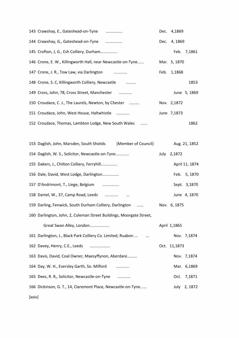
143 Crawshay, E., Gateshead-on-Tyne ............... Dec. 4,1869
144 Crawshay, G., Gateshead-on-Tyne ............... Dec. 4, 1869
145 Crofton, J, G., Esh Colliery, Durham............... Feb. 7,1861
146 Crone, E. W., Killingworth Hall, near Newcastle-on-Tyne...... Mar. 5, 1870
147 Crone, J. R., Tow Law, via Darlington ............ Feb. 1,1868
148 Crone, S. C, Killingworth Colliery, Newcastle ......... 1853
149 Cross, John, 78, Cross Street, Manchester ............ June 5, 1869
150 Croudace, C. J., The Laurels, Newton, by Chester ......... Nov. 2,1872
151 Croudace, John, West House, Haltwhistle ............ June 7,1873
152 Croudace, Thomas, Lambton Lodge, New South Wales ...... 1862
153 Daglish, John, Marsden, South Shields (Member of Council) Aug. 21, 1852
154 Daglish, W. S., Solicitor, Newcastle-on-Tyne............ July 2,1872
155 Dakers, J., Chilton Colliery, Ferryhill............... April 11, 1874
156 Dale, David, West Lodge, Darlington............... Feb. 5, 1870
157 D'Andrimont, T., Liege, Belgium ............... Sept. 3,1870
158 Daniel, W., 37, Camp Road, Leeds ............ ... June 4, 1870
159 Darling, Fenwick, South Durham Colliery, Darlington ...... Nov. 6, 1875
160 Darlington, John, 2, Coleman Street Buildings, Moorgate Street,
Great Swan Alley, London.................. April 1,1865
161 Darlington, J., Black Park Colliery Co. Limited, Ruabon ... ... Nov. 7,1874
162 Davey, Henry, C.E., Leeds .................. Oct. 11,1873
163 Davis, David, Coal Owner, Maesyffynon, Aberdare......... Nov. 7,1874
164 Day, W. H., Eversley Garth, So. Milford ............ Mar. 6,1869
165 Dees, R. R,, Solicitor, Newcastle-on-Tyne ............ Oct. 7,1871
166 Dickinson, G. T., 14, Claremont Place, Newcastle-on-Tyne...... July 2, 1872
[xxiv]

Elected.
167 Dickinson, R., Coal Owner, Shotley Bridge, Co. Durham ...... Mar. 4,1871
168 Dixon, D. W., Brotton Mines, Saltburn-by-the-Sea ......... Nov. 2,1872
169 Dixon, Nich., Dudley Colliery, Dudley, Northumberland ...... Sept. 1,1877
170 Dixon, R., Wire Rope Manufacturer, Teams, Gateshead ... ... June 5, 1875
171 Dodd, B., Bearpark Colliery, near Durham ... ... ... ... May 3, 1866
172 Dodds, J., M.P., Stockton-on-Tees ............... Mar. 7,1874
173 Douglas, C. P., Consett House, Consett, Co. Durham......... Mar. 6,1869
174 Douglas, T., Peases' West Collieries, Darlington (Mem. of Council) Aug. 21, 1852
175 Douthwaite, T., Merthyr Vale Colliery, Merthyr Tydvil ...... June 5,1869
176 Dove, G., Viewfield, Stanwix, Carlisle............... July 2,1872
177 Dowdeswell, H., Butterknowle Colliery, via Darlington ...... April 5,1873
178 Dyson, George, Middlesborough ............... June 2, 1866
179 Dyson, O. ........................... Mar. 2,1872
180 Easton, J., Nest House, Gateshead ............... 1853
181 Eckersley, Nathaniel, Standish Hall, Wigan ......... Sept. 2,1876
182 Eddison, Robert W., Steam Plough Works, Leeds......... Mar. 4, 1876
183 Eland, J. S., Accountant, Newcastle-on Tyne............ Nov. 7,1874
184 Elliot, Sir George, Bart., Houghton Hall, Fence Houses
(Past President, Member of Council) Aug. 21, 1852
185 Elliot, W. S., 2, St. George's Terrace, Roker, Sunderland...... Sept. 13, 1873
186 Elsdon, Robert, 76, Manor Road, Upper New Cross, London ... Nov. 4, 1876
187 Embleton, T. W., The Cedars, Methley, Leeds ......... Sept. 6,1855
188 Embleton, T. W., Jun., The Cedars, Methley, Leeds......... Sept. 2,1865
189 Eminson, J. B., Londonderry Offices, Seaham Harbour ...... Mar. 2,1872
190 Everard, I. B., M.E., 6, Millstone Lane, Leicester ......... Mar. 6,1869

191 Farmer, A., So. Durham Fitting Offices, West Hartlepool ...... Mar. 2,1872
192 Farrar, James, Old Foundry, Barnsley............ July 2,1872
193 Favell, Thomas M., 14, Saville Street, North Shields ...... April 5, 1873
194 Fearn, John Wilmot, Chesterfield ............... Mar. 6,1869
195 Fenwick, Barnabas, Team Colliery, Gateshead......... Aug. 2,1866
196 Fenwick, George, Banker, Newcastle-on-Tyne ......... Sept. 2,1871
197 Fenwick, Thomas, East Pontop Colliery, by Lintz Green ...... April 5, 1873
198 Ferens, Robinson, Oswald Hall, near Durham ......... April 7, 1877
199 Fidler, E., Platt Lane Colliery, Wigan, Lancashire......... Sept. 1,1866
200 Fisher, R. O, The Wern, Ystalyfera, Swansea............ July 2,1872
201 Fletcher, Geo., Hamsteels Colliery, near Durham......... Aug. 1,1874
202 Fletcher, H., Ladyshore Coll., Little Lever, Bolton, Lancashire ... Aug. 3, 1865
203 Fletcher, Jas., Manager Co-operative Collieries, Wallsend, near
Newcastle, New South Wales ............... Sept. 11,1875
204 Fletcher, J., Kelton House, Dumfries ............ July 2,1872
205 Fletcher, W., Waterhead, Ambleside............... Feb. 4, 1871
206 Foggin, William, Pensher Colliery, Fence Houses ......... Mar. 6,1875
207 Forrest, J., Assoc. Inst. C.E., Pentrehobin Hall, Mold, Flintshire ... Mar. 5, 1870
208 Forster, G. B., M.A., Backworth House, near Newcastle-upon-Tyne
(Member of Council) Nov. 5,1852
[xxv]
ELECTED.
209 Forster, J. R., Water Co.'s Office, Newcastle-on-Tyne ...... July 2,1872
210 Forster, J. T., Waldridge Colliery, Chester-le-Street ...... Aug. 1,1868
211 Forster, Richard, 51, Quayside, Newcastle-on-Tyne ...... Oct. 5,1872
212 Forster, R., South Hetton, Fence Houses ............ Sept. 5,1868
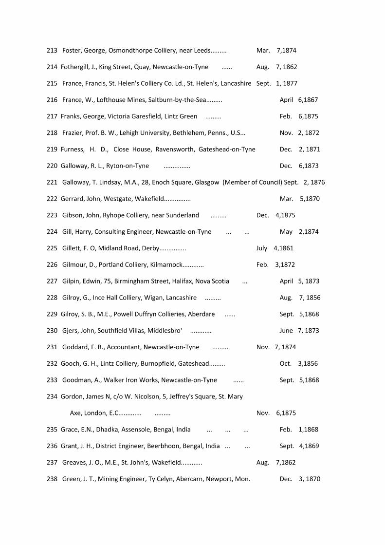
213 Foster, George, Osmondthorpe Colliery, near Leeds......... Mar. 7,1874
214 Fothergill, J., King Street, Quay, Newcastle-on-Tyne ...... Aug. 7, 1862
215 France, Francis, St. Helen's Colliery Co. Ld., St. Helen's, Lancashire Sept. 1, 1877
216 France, W., Lofthouse Mines, Saltburn-by-the-Sea......... April 6,1867
217 Franks, George, Victoria Garesfield, Lintz Green ......... Feb. 6,1875
218 Frazier, Prof. B. W., Lehigh University, Bethlehem, Penns., U.S... Nov. 2, 1872
219 Furness, H. D., Close House, Ravensworth, Gateshead-on-Tyne Dec. 2, 1871
220 Galloway, R. L., Ryton-on-Tyne ............... Dec. 6,1873
221 Galloway, T. Lindsay, M.A., 28, Enoch Square, Glasgow (Member of Council) Sept. 2, 1876
222 Gerrard, John, Westgate, Wakefield............... Mar. 5,1870
223 Gibson, John, Ryhope Colliery, near Sunderland ......... Dec. 4,1875
224 Gill, Harry, Consulting Engineer, Newcastle-on-Tyne ... ... May 2,1874
225 Gillett, F. O, Midland Road, Derby............... July 4,1861
226 Gilmour, D., Portland Colliery, Kilmarnock............ Feb. 3,1872
227 Gilpin, Edwin, 75, Birmingham Street, Halifax, Nova Scotia ... April 5, 1873
228 Gilroy, G., Ince Hall Colliery, Wigan, Lancashire ......... Aug. 7, 1856
229 Gilroy, S. B., M.E., Powell Duffryn Collieries, Aberdare ...... Sept. 5,1868
230 Gjers, John, Southfield Villas, Middlesbro' ............ June 7, 1873
231 Goddard, F. R., Accountant, Newcastle-on-Tyne ......... Nov. 7, 1874
232 Gooch, G. H., Lintz Colliery, Burnopfield, Gateshead......... Oct. 3,1856
233 Goodman, A., Walker Iron Works, Newcastle-on-Tyne ...... Sept. 5,1868
234 Gordon, James N, c/o W. Nicolson, 5, Jeffrey's Square, St. Mary
Axe, London, E.C............. ......... Nov. 6,1875
235 Grace, E.N., Dhadka, Assensole, Bengal, India ... ... ... Feb. 1,1868
236 Grant, J. H., District Engineer, Beerbhoon, Bengal, India ... ... Sept. 4,1869
237 Greaves, J. O., M.E., St. John's, Wakefield............ Aug. 7,1862
238 Green, J. T., Mining Engineer, Ty Celyn, Abercarn, Newport, Mon. Dec. 3, 1870
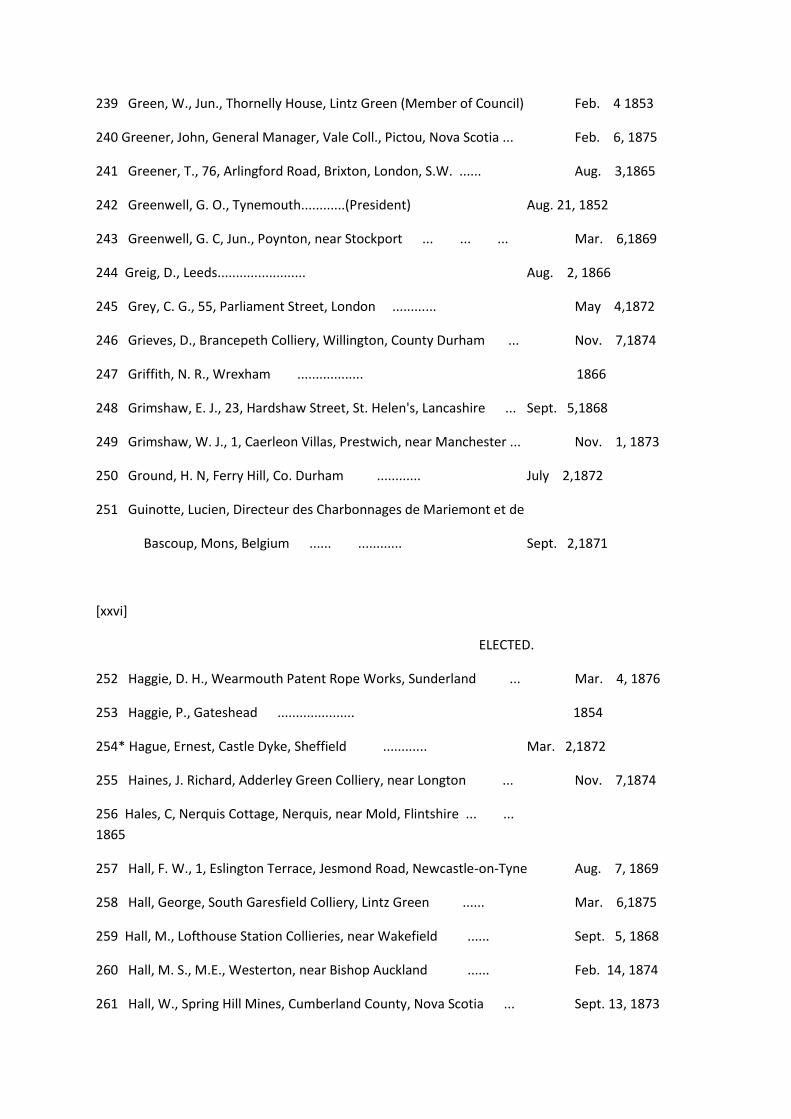
239 Green, W., Jun., Thornelly House, Lintz Green (Member of Council) Feb. 4 1853
240 Greener, John, General Manager, Vale Coll., Pictou, Nova Scotia ... Feb. 6, 1875
241 Greener, T., 76, Arlingford Road, Brixton, London, S.W. ...... Aug. 3,1865
242 Greenwell, G. O., Tynemouth............(President) Aug. 21, 1852
243 Greenwell, G. C, Jun., Poynton, near Stockport ... ... ... Mar. 6,1869
244 Greig, D., Leeds........................ Aug. 2, 1866
245 Grey, C. G., 55, Parliament Street, London ............ May 4,1872
246 Grieves, D., Brancepeth Colliery, Willington, County Durham ... Nov. 7,1874
247 Griffith, N. R., Wrexham .................. 1866
248 Grimshaw, E. J., 23, Hardshaw Street, St. Helen's, Lancashire ... Sept. 5,1868
249 Grimshaw, W. J., 1, Caerleon Villas, Prestwich, near Manchester ... Nov. 1, 1873
250 Ground, H. N, Ferry Hill, Co. Durham ............ July 2,1872
251 Guinotte, Lucien, Directeur des Charbonnages de Mariemont et de
Bascoup, Mons, Belgium ...... ............ Sept. 2,1871
[xxvi]
ELECTED.
252 Haggie, D. H., Wearmouth Patent Rope Works, Sunderland ... Mar. 4, 1876
253 Haggie, P., Gateshead ..................... 1854
254* Hague, Ernest, Castle Dyke, Sheffield ............ Mar. 2,1872
255 Haines, J. Richard, Adderley Green Colliery, near Longton ... Nov. 7,1874
256 Hales, C, Nerquis Cottage, Nerquis, near Mold, Flintshire ... ...
1865
257 Hall, F. W., 1, Eslington Terrace, Jesmond Road, Newcastle-on-Tyne Aug. 7, 1869
258 Hall, George, South Garesfield Colliery, Lintz Green ...... Mar. 6,1875
259 Hall, M., Lofthouse Station Collieries, near Wakefield ...... Sept. 5, 1868
260 Hall, M. S., M.E., Westerton, near Bishop Auckland ...... Feb. 14, 1874
261 Hall, W., Spring Hill Mines, Cumberland County, Nova Scotia ... Sept. 13, 1873

262 Hall, Wm., Thornley Colliery, County Durham ......... Dec. 4,1875
263 Hall, William F., Haswell Colliery, Fence Houses......... May 13,1858
264 Hann, Edmund, New Tredegar Colliery, via Cardiff......... Sept. 5, 1868
265 Harbottle, W. H., Orrell Colliery, near Wigan ......... Dec. 4, 1875
266 Hardy, Jos., Preston Colliery, North Shields............ June 2,1877
267 Hargreaves, William, Rothwell Haigh, Leeds ......... Sept. 5,1868
268 Harle, Richard, Browney Colliery, Durham............ April 7,1877
269 Harle, William, Pagebank Colliery, near Durham......... Oct. 7,1876
270 Harrison, R., Eastwood, near Nottingham ............ 1861
271 Harrison, T., Great Western Colliery, Pontypridd, Glamorganshire Aug. 2, 1873
272 Harrison, T. E., C.E., Central Station, Newcastle-on-Tyne...... May 6,1853
273 Harrison, W. B., Brownhills Collieries, near Walsall ...... April 6,1867
274 Haswell, G. H., 11, South Preston Terrace, North Shields...... Mar. 2, 1872
275 Hay, J., Jun., Widdrington Colliery, Acklington ......... Sept. 4, 1869
276 Heckels, Matthew, Castle Eden Colliery, Co. Durham ...... April 11, 1874
277 Heckels, W. J., South Medomsley Colliery, Dipton, by Lintz Green May 2, 1863
278 Hedley, Edw., 2, Church Street, London Road, Derby ...... Dec. 2,1858
279 Hedley, J. J., Consett Collieries, Leadgate, County Durham ... April 6,1872
280 Hedley, J. L., Flooker's Brook, Chester ............ Feb. 5, 1870
281 Hedley, T. F., Valuer, Sunderland ............... Mar. 4,1871
282 Hedley, W. H., Consett Collieries, Medomsley, Newcastle-on-Tyne
(Member of Council) 1864
283 Henderson, H., Pelton Colliery, Chester-le-Street ......... Feb. 14,1874
284 Heppell, T., Leafield House, Birtley, Fence Houses (Mem. of Council) Aug. 6, 1863
285 Heppell, W., Brancepeth Colliery, Willington, County Durham ... Mar. 2, 1872
286 Herdman, J., Park Crescent, Bridgend, Glamorganshire ... ... Oct. 4,1860
287 Heslop, C, Lingdale Mines, via Guisborough............ Feb. 1,1868

288 Heslop, Grainger, Whitwell Colliery, Sunderland ......... Oct. 5,1872
289 Heslop, J., Hucknall Torkard Colliery, near Nottingham ...... Feb. 6,1864
290 Hetherington, D., Coxlodge Colliery, Newcastle-on-Tyne...... 1859
291*Hewitt, G. C, Coal Pit Heath Colliery, near Bristol ...... June 3, 1871
292 Hewlett, A., Haigh Colliery, Wigan, Lancashire ......... Mar. 7,1861
293 Hick, G. W., 14, Blenheim Terrace, Leeds ............ May 4, 1872
294 Higson, Jacob, 94, Cross Street, Manchester............ 1861
295 Higson, P., Crown Chambers, 18, Booth Street, Manchester...... Aug. 3, 1865
296 Hill, Leslie C, Bartholomew House, London, E.C.......... Nov. 6, 1875
297 Hilton, J., Standish and Shevington Collieries, near Wigan ... Dec, 7 1867
[xxvii]
ELECTED.
298 Hilton, T. W., Wigan Coal and Iron Co., Limited, Wigan...... Aug. 3,1865
299 Hindmarsh, Thomas, Cowpen Lodge, Blyth, Northumberland ... Sept. 2,1876
300 Hodgson, J. W., Dipton Colliery, via Lintz Green Station...... Feb. 5,1870
301 Holliday, Martin, M.E., Peases' West Collieries, Crook ...... May 1,1875
302 Holmes, C., Grange Hill, near Bishop Auckland ......... April 11, 1874
303 Homer, Charles J., Mining Engineer, Stoke-on-Trent ...... Aug. 3, 1865
304 Hood, A., 6, Bute Crescent, Cardiff ............... April 18, 1861
305 Hope, George, Newbottle Colliery, Fence Houses ......... Feb. 3,1877
306 Hornsby, H., Whitworth Terrace, via Spennymoor, Co. Durham ... Aug. 1,
1874
307 Horsley, W., Whitehill Point, Percy Main ............ Mar. 5,1857
308 Hoskold, H. D., C. and M.E., F.R.G.S., F.G.S., M. Soc. A., &c,
Fonda de Oriente, Barcelona, Spain ... ... ... ... April 1, 1871
309 Howard, W. F., 13, Cavendish Street, Chesterfield ......... Aug. 1,1861
310 Hudson, James, Albion Mines, Pictou, Nova Scotia......... 1862
311 Hughes, H. E., Aldridge Colliery, near Walsall, Staffordshire ... Nov. 6,1869
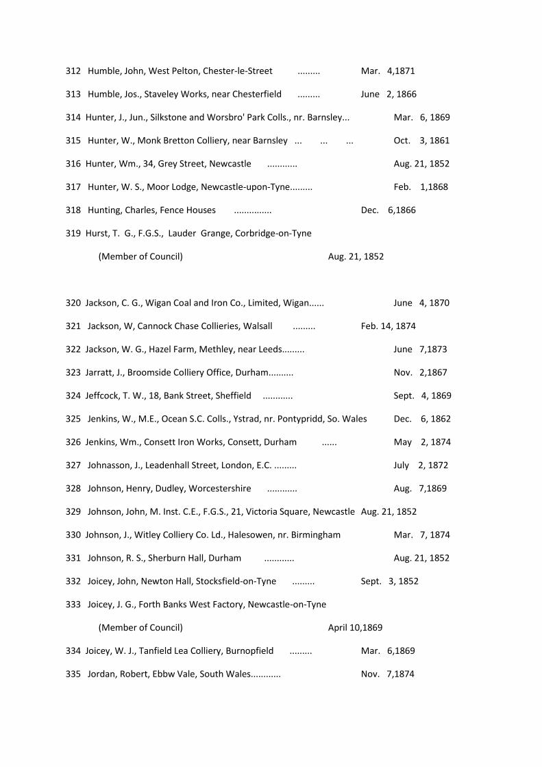
312 Humble, John, West Pelton, Chester-le-Street ......... Mar. 4,1871
313 Humble, Jos., Staveley Works, near Chesterfield ......... June 2, 1866
314 Hunter, J., Jun., Silkstone and Worsbro' Park Colls., nr. Barnsley... Mar. 6, 1869
315 Hunter, W., Monk Bretton Colliery, near Barnsley ... ... ... Oct. 3, 1861
316 Hunter, Wm., 34, Grey Street, Newcastle ............ Aug. 21, 1852
317 Hunter, W. S., Moor Lodge, Newcastle-upon-Tyne......... Feb. 1,1868
318 Hunting, Charles, Fence Houses ............... Dec. 6,1866
319 Hurst, T. G., F.G.S., Lauder Grange, Corbridge-on-Tyne
(Member of Council) Aug. 21, 1852
320 Jackson, C. G., Wigan Coal and Iron Co., Limited, Wigan...... June 4, 1870
321 Jackson, W, Cannock Chase Collieries, Walsall ......... Feb. 14, 1874
322 Jackson, W. G., Hazel Farm, Methley, near Leeds......... June 7,1873
323 Jarratt, J., Broomside Colliery Office, Durham.......... Nov. 2,1867
324 Jeffcock, T. W., 18, Bank Street, Sheffield ............ Sept. 4, 1869
325 Jenkins, W., M.E., Ocean S.C. Colls., Ystrad, nr. Pontypridd, So. Wales Dec. 6, 1862
326 Jenkins, Wm., Consett Iron Works, Consett, Durham ...... May 2, 1874
327 Johnasson, J., Leadenhall Street, London, E.C. ......... July 2, 1872
328 Johnson, Henry, Dudley, Worcestershire ............ Aug. 7,1869
329 Johnson, John, M. Inst. C.E., F.G.S., 21, Victoria Square, Newcastle Aug. 21, 1852
330 Johnson, J., Witley Colliery Co. Ld., Halesowen, nr. Birmingham Mar. 7, 1874
331 Johnson, R. S., Sherburn Hall, Durham ............ Aug. 21, 1852
332 Joicey, John, Newton Hall, Stocksfield-on-Tyne ......... Sept. 3, 1852
333 Joicey, J. G., Forth Banks West Factory, Newcastle-on-Tyne
(Member of Council) April 10,1869
334 Joicey, W. J., Tanfield Lea Colliery, Burnopfield ......... Mar. 6,1869
335 Jordan, Robert, Ebbw Vale, South Wales............ Nov. 7,1874

336 Joseph, D. Davis, Ty Draw, Pontypridd, South Wales ...... April 6, 1872
337 Joseph, T., Ty Draw, near Pontypridd, South Wales......... April 6,1872
338 Kelsey, W., 41, Fawcett Street, Sunderland............ Mar. 7,1874
339 Kendall, John D., Roper Street, Whitehaven ......... Oct. 3,1874
[xxviii]
ELECTED.
340 Kennedy, Myles, M.E., Hill Foot, Ulverstone ......... June 6, 1868
341 Kimpton, J. G., 40, St. Mary's Gate, Derby ............ Oct. 5, 1872
342 Kirkby, J. W., Ashgrove, Windygates, Fife............ Feb. 1,1873
343 Kirkwood, William, Larkhall Colliery, Hamilton......... Aug. 7,1869
344 Kirsopp, John, Team Colliery, Gateshead ............ April 5,1873
345 Knowles, A., High Bank, Pendlebury, Manchester......... Dec. 5,1856
346 Knowles, John, Westwood, Pendlebury, Manchester ...... Dec. 5,1856
347 Knowles, Thomas, Ince Hall, Wigan............... Aug. 1,1861
348 Kyrke, R. H. V., Westminster Chambers, Wrexham......... Feb. 5,1870
349 Lackland, J. J., Albion Street, Hanley, Staffordshire ...... Mar. 7,1874
350 Laidler, W. J......................... Mar. 4,1876
351 Lamb, R., Cleator Moor Colliery, near Whitehaven ......... Sept. 2, 1865
352 Lamb, R. O., Gibside, Lintz Green, Newcastle-on-Tyne ...... Aug. 2,1866
353 Lamb, Richard W., Coal Owner, Newcastle-on-Tyne......... Nov. 2,1872
354 Lambert, M. W., 9, Queen Street, Newcastle-on-Tyne ...... July 2,1872
355 Lancaster, John, Bilton Grange, Rugby ............ July 4,1861
356 Lancaster, J., Jun., Anfield House, Willes Road, Leamington ... Mar. 2, 1865
357 Lancaster, S., Nantyglo & Blaina Steam Coal Collieries, Blaina, Mon. Aug. 3, 1865
358 Landale, A., Lochgelly Iron Works, Fifeshire, N.B. ......... Dec. 2,1858
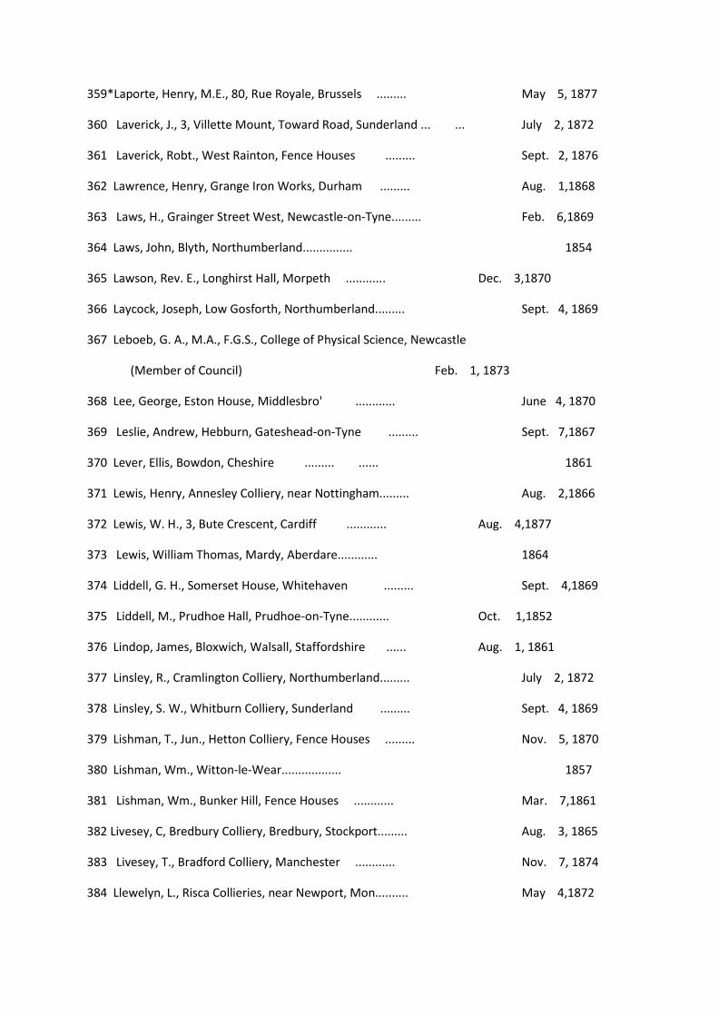
359*Laporte, Henry, M.E., 80, Rue Royale, Brussels ......... May 5, 1877
360 Laverick, J., 3, Villette Mount, Toward Road, Sunderland ... ... July 2, 1872
361 Laverick, Robt., West Rainton, Fence Houses ......... Sept. 2, 1876
362 Lawrence, Henry, Grange Iron Works, Durham ......... Aug. 1,1868
363 Laws, H., Grainger Street West, Newcastle-on-Tyne......... Feb. 6,1869
364 Laws, John, Blyth, Northumberland............... 1854
365 Lawson, Rev. E., Longhirst Hall, Morpeth ............ Dec. 3,1870
366 Laycock, Joseph, Low Gosforth, Northumberland......... Sept. 4, 1869
367 Leboeb, G. A., M.A., F.G.S., College of Physical Science, Newcastle
(Member of Council) Feb. 1, 1873
368 Lee, George, Eston House, Middlesbro' ............ June 4, 1870
369 Leslie, Andrew, Hebburn, Gateshead-on-Tyne ......... Sept. 7,1867
370 Lever, Ellis, Bowdon, Cheshire ......... ...... 1861
371 Lewis, Henry, Annesley Colliery, near Nottingham......... Aug. 2,1866
372 Lewis, W. H., 3, Bute Crescent, Cardiff ............ Aug. 4,1877
373 Lewis, William Thomas, Mardy, Aberdare............ 1864
374 Liddell, G. H., Somerset House, Whitehaven ......... Sept. 4,1869
375 Liddell, M., Prudhoe Hall, Prudhoe-on-Tyne............ Oct. 1,1852
376 Lindop, James, Bloxwich, Walsall, Staffordshire ...... Aug. 1, 1861
377 Linsley, R., Cramlington Colliery, Northumberland......... July 2, 1872
378 Linsley, S. W., Whitburn Colliery, Sunderland ......... Sept. 4, 1869
379 Lishman, T., Jun., Hetton Colliery, Fence Houses ......... Nov. 5, 1870
380 Lishman, Wm., Witton-le-Wear.................. 1857
381 Lishman, Wm., Bunker Hill, Fence Houses ............ Mar. 7,1861
382 Livesey, C, Bredbury Colliery, Bredbury, Stockport......... Aug. 3, 1865
383 Livesey, T., Bradford Colliery, Manchester ............ Nov. 7, 1874
384 Llewelyn, L., Risca Collieries, near Newport, Mon.......... May 4,1872
[xxix]
ELECTED.
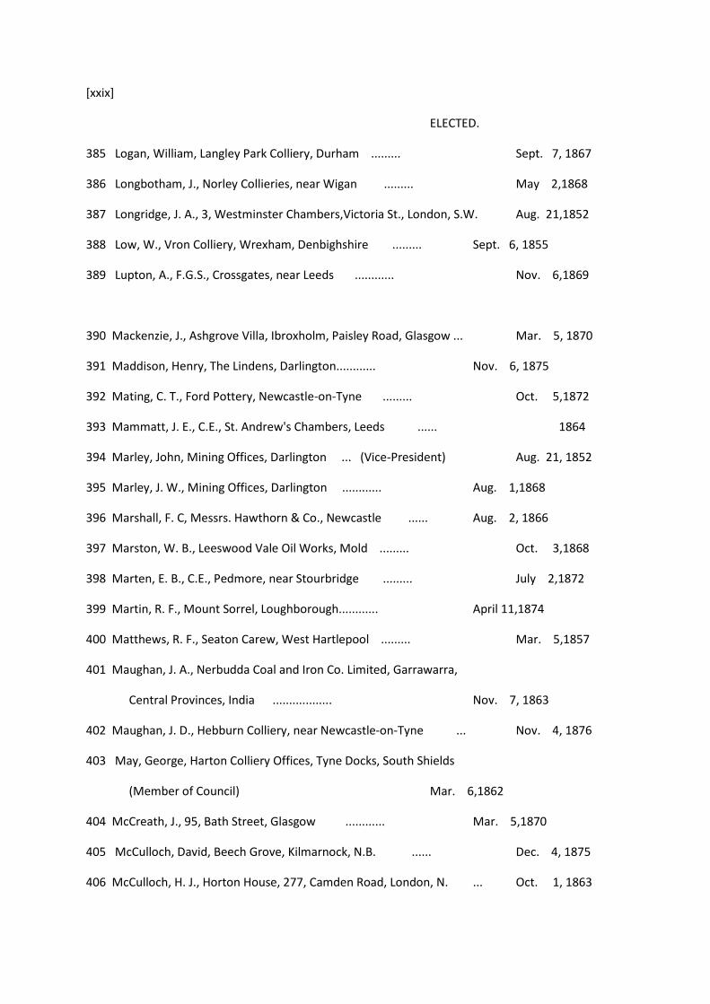
385 Logan, William, Langley Park Colliery, Durham ......... Sept. 7, 1867
386 Longbotham, J., Norley Collieries, near Wigan ......... May 2,1868
387 Longridge, J. A., 3, Westminster Chambers,Victoria St., London, S.W. Aug. 21,1852
388 Low, W., Vron Colliery, Wrexham, Denbighshire ......... Sept. 6, 1855
389 Lupton, A., F.G.S., Crossgates, near Leeds ............ Nov. 6,1869
390 Mackenzie, J., Ashgrove Villa, Ibroxholm, Paisley Road, Glasgow ... Mar. 5, 1870
391 Maddison, Henry, The Lindens, Darlington............ Nov. 6, 1875
392 Mating, C. T., Ford Pottery, Newcastle-on-Tyne ......... Oct. 5,1872
393 Mammatt, J. E., C.E., St. Andrew's Chambers, Leeds ...... 1864
394 Marley, John, Mining Offices, Darlington ... (Vice-President) Aug. 21, 1852
395 Marley, J. W., Mining Offices, Darlington ............ Aug. 1,1868
396 Marshall, F. C, Messrs. Hawthorn & Co., Newcastle ...... Aug. 2, 1866
397 Marston, W. B., Leeswood Vale Oil Works, Mold ......... Oct. 3,1868
398 Marten, E. B., C.E., Pedmore, near Stourbridge ......... July 2,1872
399 Martin, R. F., Mount Sorrel, Loughborough............ April 11,1874
400 Matthews, R. F., Seaton Carew, West Hartlepool ......... Mar. 5,1857
401 Maughan, J. A., Nerbudda Coal and Iron Co. Limited, Garrawarra,
Central Provinces, India .................. Nov. 7, 1863
402 Maughan, J. D., Hebburn Colliery, near Newcastle-on-Tyne ... Nov. 4, 1876
403 May, George, Harton Colliery Offices, Tyne Docks, South Shields
(Member of Council) Mar. 6,1862
404 McCreath, J., 95, Bath Street, Glasgow ............ Mar. 5,1870
405 McCulloch, David, Beech Grove, Kilmarnock, N.B. ...... Dec. 4, 1875
406 McCulloch, H. J., Horton House, 277, Camden Road, London, N. ... Oct. 1, 1863

407 McCulloch, W., 178, Gresham House, Old Broad Street, London, E.C. Nov. 7, 1874
408 McGhie, T., Cannock, Staffordshire ............... Oct, 1,1857
409 McMurtrie, J., Radstock Colliery, Bath ............ Nov. 7,1863
410 Meik, Thomas, C.E., 6, York Place, Edinburgh ...... ... June 4, 1870
411 Merivale, J. H., 2, Victoria Villas, Newcastle ......... May 5,1877
412 Miller, Robert, Strafford Collieries, near Barnsley......... Mar. 2,1865
413 Mills, M. H., Duckmanton Lodge, Chesterfield ......... Feb. 4,1871
414 Mitchell, Chas., Jesmond, Newcastle-on-Tyne ......... April 11,1874
415 Mitchell, Joseph, Worsbro' Dale, near Barnsley ........ Feb, 14, 1874
416 Mitchinson, R., Jun., Pontop Coll., Lintz Green Station, Co. Durham Feb. 4, 1865
417 Moffat, T., Montreal Iron Ore Works, Whitehaven ...... Sept. 4, 1869
418 Monkhouse, Jos., Yeat House, Frizington, Whitehaven ...... June 4, 1863
419 Moor, T., Cambois Colliery, Blyth ............... Oct. 3,1868
420 Moor, Wm., Jun., Hetton Colliery, Fence Houses ......... July 2,1872
421 Moore, R. W., Colliery Office, Whitehaven ............ Nov. 5,1870
422 Moore, T. H., Smeaton Park, Inveresk, Edinburgh......... Feb. 2, 1867
423 Morison, D. P., 21, Collingwood St., Newcastle (Member of Council) 1861
424 Morrell, John, Darlington .................. Oct. 7, 1876
425 Morris, W., Waldridge Colliery, Chester-le-Street, Fence Houses ... 1858
426*Morton, H. J., 4, Royal Crescent, Scarborough ......... 1861
427 Morton, H. T., Lambton, Fence Houses ............ Aug. 21, 1852
428 Moses, Wm., Lumley Colliery, Fence Houses............ Mar. 2,1872
[xxx]
ELECTED.
429 Muckle, John, Monk Bretton, Barnsley ............ Mar. 7, 1861
430 Mulcaster, W., Jun., M.E., Croft House, Aspatria, near Carlisle ... Dec. 3, 1870
431 Mulvany, W. T., Pempelfort, Dusseldorf-on-the-Rhine ...... Dec. 3,1857

432 Mundle, Arthur, 7, Collingwood Street, Newcastle-on-Tyne ... June 5, 1875
433 Mundle, W., Redesdale Mines, Bellingham ............ Aug. 2, 1873
434 Nanson, J. ........................... Dec. 4,1869
435*Nasse, Rudolph, Konigl Bergwerks Director, Louisenthal, Saarbrucken,
Prussia 1869
436 Naylor, J. T., 10, West Clayton Street, Newcastle-on-Tyne...... Dec. 6, 1866
437 Nelson, J., C.E., Marine and Stationary Engine Works, Gateshead Oct. 4, 1866
438 Nevin, John, Mirfield, Yorkshire ............... May 2,1868
439 Newall, R. S., Ferndene, Gateshead ............... May 2,1863
440 Nicholson, E., jun., Beamish Colliery, Chester-le-Street ...... Aug. 7,1869
441 Nicholson, J. W., 36, Crown St., Elswick Road, Newcastle-on-Tyne Oct. 11, 1873
442 Nicholson, Marshall, Middleton Hall, Leeds ......... Nov. 7,1863
443 Noble, Captain, Jesmond, Newcastle-upon-Tyne ......... Feb. 3,1866
444 North, P. W., F.G.S., Rowley Hall Colliery, Dudley, Staffordshire ... Oct. 6,1864
445 Nuttall, Thomas, Broad Street, Bury, Lancashire......... Sept. 11,1875
446 Ogden, John M., Solicitor, Sunderland............... Mar. 5, 1857
447 Ogilvie, A. Graeme, 4, Great George Street, Westminster, London Mar. 3, 1877
448 Oliver, Robert, Charlaw Colliery, near Durham ......... Nov. 6,1875
449 Pacey, T., Bishop Auckland .................. April 10, 1869
450 Palmer, A. S., Wardley Hall, near Newcastle-on-Tyne ...... July 2,1872
451 Palmer, C. M., M.P., Quay, Newcastle-upon-Tyne ......... Nov. 5,1852
452 Pamely, C, Radstock Coal Works, near Bath............ Sept. 5,1868
453 Panton, P. S., Silksworth Colliery, Sunderland ......... Oct. 5,1867
454 Parkin, O, West Haddon Villa, Coatham, Redcar ......... June 5,1875

455 Parkin, John, Westbourne Grove, Redcar, Yorkshire......... April 11, 1874
456 Parrington, M. W., Wearmouth Colliery, Sunderland ...... Dec. 1, 1864
457 Parton, T., F.G.S., Ash Cottage, Birmingham Road, West Bromwich Oct. 2, 1869
458 Pattison, John, Engineer, Naples ............... Nov. 7,1874
459 Peace, M. W., Wigan, Lancashire ............... July 2, 1872
460 Peacock, David, West Bromwich ............... Aug. 7, 1869
461 Pearce, P. H., Bowling Iron Works, Bradford ......... Oct. 1,1857
462 Pease, J. W., M.P., Hutton Hall, Guisbro', Yorkshire ...... Mar. 5,1857
463 Peel, John, Wharncliffe and Silkstone Coll., Wortley, near Sheffield Nov. 1, 1860
464 Peel, John, Horsley Colliery, Wylam-on-Tyne ......... Mar. 3, 1877
465 Peile, William, Rosemount, Roath, Cardiff ... ... ... ... Oct. 1, 1863
466 Penman, J. H., 2, Clarence Buildings, Booth Street, Manchester ... Mar. 7, 1874
467 Perrot, S. W. ........................ June 2,1866
468 Philipson, H., 8, Queen Street, Newcastle-upon-Tyne ...... Oct. 7,1871
469 Pickup, P. W., Dunkenhalgh Collieries, Accrington, Lancashire ... Feb. 6, 1875
470 Pinching, Archd. E., The Terrace, Gravesend ... ... ... May 5,1877
471 Potter, Addison, Heaton Hall, Newcastlc-on-Tyne......... Mar. 6,1869
[xxxi]
ELECTED.
472 Potter, A. M., Shiremoor Coll., Northumberland (Member of Council) Feb. 3, 1872
473 Potter, C. J., Heaton Hall, Newcastle-on-Tyne ......... Oct. 3,1874
474*Potter, W. A., Cramlington House, Northumberland ...... 1853
475 Price, John, Messrs. Palmer Brothers & Co., Jarrow-on-Tyne ... Mar. 3,1877
476 Price, J. R., Standish, near Wigan ............... Aug. 7,1869
477 Priestman, Jon., Coal Owner, Newcastle-on-Tyne ......... Sept. 2,1871
478 Pringle, Edward, Choppington Colliery. Northumberland...... Aug. 4, 1877

479 Ramsay, J. A., Westbrook, Darlington............... Mar. 6,1869
480 Ramsay, J. T., Walbottle Hall, nr. Blaydon-on-Tyne (Mem. of Council) Aug. 3, 1853
481 Ramsay, T. D. ........................ Mar. 1,1866
482 Ramsay, Wm., Tursdale Colliery, County Durham ......... Sept. 11, 1875
483 Reed, Robert, Felling Colliery, Gateshead ............ Dec. 3, 1863
484 Rees, Daniel, Glandare, Aberdare ............... 1862
485 Refeen, Wm., Teplitz, Bohemia.................. Oct, 5,1872
486 Reid, Andrew, Newcastle-on-Tyne ............... April 2, 1870
487 Richards, E. W., Messrs. Bolckow, Vaughan, & Co., Middlesbro' ... Aug 5, 1876
488 Richards, G. C, M.E„ Woodhouse, near Sheffield ......... June 5,1875
489 Richardson, H, Backworth Colliery, Newcastle-on-Tyne ...... Mar. 2,1865
490 Richardson, J. W., Iron Shipbuilder, Newcastle-on-Tyne ...... Sept. 3,1870
491 Ridley, G., Trinity Chambers, Newcastle-on-Tyne ......... Feb. 4, 1865
492 Ridley, J. H., R. & W. Hawthorn's, Newcastle-on-Tyne ...... April 6, 1872
493 Ridyard, J., Bridgewater Offices, Walkden, nr. Bolton-le-Moors, Lan. Nov. 7, 1874
494 Rigby, John, Ash Villa, Alsager, Stoke-upon-Trent......... Feb. 5,1876
495 Ritson, U. A, 6, Queen Street, Newcastle-on-Tyne ......... Oct. 7,1871
496 Ritson, W. A., Shilbottle Colliery, near Alnwick ......... April 2, 1870
497 Robertson, W., M.E., 123, St. Vincent Street, Glasgow ...... Mar. 5, 1870
498 Robinson, G. C., Brereton and Hayes Colls., Rugeley, Staffordshire... Nov. 5, 1870
499 Robinson, H., C.E., 7, Westminster Chambers, London ...... Sept. 3,1870
500 Robinson, John, Hebburn Colliery, near Newcastle-on-Tyne ... Nov. 4, 1876
501 Robinson, R., Howlish Hall, near Bishop Auckland.......... Feb. 1,1868
502 Robson, E., Middlesbro'-on-Tees.................. April 2,1870
503 Robson, J. S., Butterknowle Colliery, via Darlington......... 1853
504 Robson, J. T., Cambuslang, Glasgow ............... Sept. 4,1869
505 Robson, Thomas, Lumley Colliery, Fence Houses ......... Oct. 4,1860
506 Rogerson, John, Croxdale Hall, Durham ............ Mar. 6, 1869
507 Roscamp, J., Rosedale Lodge, near Pickering, Yorkshire ...... Feb. 2, 1867
508 Roseby, John, Haverholme House, Brigg, Lincolnshire ...... Nov. 2, 1872
509 Ross, A. ........................... Oct. 1,1857
510 Ross, J. A. G., Consulting Engineer, Bath Lane, Newcastle...... July 2, 1872
511 Rosser, W., Mineral Surveyor, Llanelly, Carmarthenshire ... ...
1856
512 Rothwell, R. P., 27, Park Place, New York. ........... Mar. 5, 1870
513 Routledge, Jos., Ryhope Colliery, Sunderland ......... Sept. 11, 1875
514 Routledge, J. L., Ryhope Colliery, Sunderland ......... Oct. 7,1876
515 Routledge, Wm., Sydney, Cape Breton ............ Aug. 6, 1857
516 Rowley, J. C, Shagpoint Colliery, Otago, New Zealand ...... Dec. 4,1875
517 Rutherford, J., Halifax, Nova Scotia............... 1866
[xxxii]
ELECTED.
518 Rutherford, W., Marden House, Whitley, Newcastle-on-Tyne ... Oct. 3,1874
519 Rutter, Thos., Blaydon Main Colliery, Blaydon-on-Tyne ...... May 1,1875
520 Ryder, W. J. H., Forth Street Brass Works, Newcastle-on-Tyne ... Nov. 4, 1876
521 Saint, George, Vauxhall Collieries, Ruabon, North Wales...... April 11, 1874
522 Scarth, W. T., Raby Castle, Darlington ............ April 4, 1868
523 Scott, Andrew, Broomhill Colliery, Acklington ......... Dec. 7,1867
524 Scott, C. F., Gateshead Fell Colliery, Gateshead-on-Tyne ...... April 11, 1874
525 Scoular, G., Parkside, Frizington, Cumberland ......... July 2,1872
526 Seddon, J. F., Great Harwood Collieries, near Accrington ... ... June 1,1867
527 Seddon, W., Dunkirk Collieries, Dukiufield ............ Oct. 5,1865
528 Shallis, F. W., M. and J. Pritchard, 9, Gracechurch Street, London April 6, 1872
529 Shaw, John, Neptune Engine Works, Low Walker, Newcastle ... Nov. 6,1875

530 Shaw, W., Jun., Wolsingham, via Darlington............ June 3,1871
531 Shiel, John, Framwellgate Colliery, County Durham ...... May 6, 1871
532 Shone, Isaac, Pentrefelin House, Wrexham............ 1858
533 Shortrede, T., Park House, Winstanley, Wigan ......... April 3,1856
534 Shute, C. A., Westoe, South Shields ............... April 11, 1874
535 Simpson, J., Heworth Colliery, near Gateshead-on-Tyne ...... Dec. 6, 1866
536 Simpson, Jos., Springhill Mines, Cumberland Co., Nova Scotia ... Mar. 3,1873
537 Simpson, J. B., Hedgefield House, Blaydon-on-Tyne(Vice-President) Oct. 4, 1860
538 Simpson, J. C......................... April 7,1877
539 Simpson, P., Moor House, Ryton-on-Tyne ............ Aug. 21, 1852
540 Simpson, Robt., Drummond Colliery, Westville, Pictou, N.S. ... Dec. 4,1875
511 Sinclair, James, 48, Blackfriars Street, Manchester......... May 6,1876
542 Slinn, T., 2, Choppington Street, Westmorland Road, Newcastle ... July 2, 1872
543 Small, G., Duffield Road, Derby................. June 4,1870
544 Smith, G. F., Grovehurst, Tunbridge Wells ............ Aug. 5, 1853
545 Smith, J., Bickershaw Colliery, Leigh, near Manchester ...... Mar. 7,1874
546*Smith, R. Clifford, Parkfield, Swinton, Manchester ...... Dec. 5, 1874
547 Smith, T., Sen., M.E., Cinderford Villas, nr. Newnham, Gloucester... May, 5, 1877
518 Smith, T. E., M.P., Gosforth House, Dudley, Northumberland ... Feb. 5, 1870
549 Smith, T. E., Phoenix Foundry, Newgate Street, Newcastle-on-Tyne Dec. 5, 1874
550 Snowdon, T., Jun., West Bitchburn Coll., nr. Towlaw, via Darlington Sept. 4,
1869
551 Sopwith, A., Cannock Chase Collieries, near Walsall... ... ... Aug. 1,1868
552 Sopwith, Thos., 6, Great George St., Westminster, London, S.W. ... Mar. 3, 1877
553 Southern, R., Burleigh House, The Parade, Tredegarville, Cardiff... Aug. 3, 1865
554 Southworth, Thos., Hindley Green Collieries, near Wigan...... May 2,1874
555 Spark, H. K., Startforth House, Barnard Castle ......... 1856
556 Spence, G. .......................... June 7,1873
557 Spence, James, Clifton and Millgramfitz Collieries, Workington ... Nov. 7, 1874
558 Spencer, John, Westgate Road, Newcastle-on-Tyne......... Sept. 4,1869
559 Spencer, M., Newburn, near Newcastle-on-Tyne ......... Sept. 4, 1869
560 Spencer, T., Ryton, Newcastle-on-Tyne ............ Dec. 6,1866
561 Spencer, W., Cross House Chambers, Westgate Road, Newcastle ... Aug. 21, 1852
562 Steavenson, A. L., Durham ... ... ... (Vice-President) Dec. 6, 1855
563 Steavenson, D. F., B.A., LL.B., Barrister-at-Law, Cross House,
Westgate Road, Newcastle-on-Tyne ... ... ...... April 1,1871
[xxxiii]
ELECTED.
564 Steele, Chas., Bolton Colliery, Mealsgate, Cumberland ...... June 7,1873
565 Steele, Charles R., Almburgh House, near Maryport ...... Mar. 3,1864
566 Stephenson, G. R., 9, Victoria Chambers, Westminster, London, S.W. Oct. 4, 1860
567 Stephenson, W. H., Elswick House, Newcastle-on-Tyne ...... Mar. 7,1867
568 Stevenson, R. ........................ Feb. 5,1876
569 Stobart, W., Wearmouth Colliery, Sunderland ......... July 2,1872
570 Stokoe, Joseph, Houghton-le-Spring, Fence Houses ... ... April 11, 1874
571 Storey, Thos. E., Clough Hall Iron Works, Kidsgrove, Staffordshire Feb. 5, 1876
572 Straker, John, Stagshaw House, Corbridge-on-Tyne ...... May 2, 1867
573 Straker, J. H., Willington House, Co. Durham ......... Oct. 3,1874
574 Stratton, T. H. M., Seaham Colliery, Sunderland ......... Dec. 3, 1870
575 Swallow, J., Pontop Hall, Lintz Green ............ May 2,1874
576 Swallow, R. T., Springwell, Gateshead ............ 1862
577 Swan, H. F., Shipbuilder, Newcastle-on-Tyne............ Sept. 2,1871
578 Swan, J. G., Upsall Hall, near Middlesbro' ............ Sept. 2, 1871
579 Swann, C. G., Sec, General Mining Asso. Ld., 6, New Broad St., London Aug. 7,1875

580 Tate, Simon, Kimblesworth Colliery, Co. Durham ......... Sept. 11, 1875
581 Taylor, George, Brotton Mines, Saltburn-by-the-Sea ...... June 5,1875
582 Taylor, Hugh, King Street, Quay, Newcastle-on-Tyne ...... Sept. 5,1856
583 Taylor, John B., Wollescote House, near Stourbridge ...... May 3,1873
584 Taylor, T., King Street, Quay, Newcastle-on-Tyne......... July 2,1872
585 Taylor-Smith, Thomas, Urpeth Hall, Chester-le-Street ...... Aug. 2,1866
586 Thomas, A., Bilson House, near Newnham, Gloucestershire...... Mar. 2, 1872
587 Thompson, James, Hurworth, Darlington ............ June 2, 1866
588 Thompson, John, Boughton Hall, Chester ............ Sept. 2,1865
589 Thompson, J., Hilton House, Blackrod, near Chorley......... April 6, 1867
590 Thompson, R., Jun., Rodridge House, Wingate, Co. Durham ... Sept. 7, 1867
591 Thompson, T. C, Milton Hall, Carlisle............... May 4, 1854
592 Thomson, John, South Skelton Mines, via Guisbro'......... April 7,1877
593 Thomson, Jos. F., Manvers Main Colliery, Rotherham ...... Feb. 6, 1875
594 Thubron, N., Broadoak Colliery, Longhor, near Swansea ...... Oct. 3,1874
595 Tinn, J., C.E., Ashton Iron Rolling Mills, Bower Ashton, Bristol ... Sept. 7, 1867
596 Tone, J. F., C.E......................... Feb. 7,1856
597 Tylden-Wright, C, Shireoaks Colliery, Worksop, Notts ...... 1862
598 Tylor, Alfred E., 123, Bute Street, Cardiff............ April 1, 1876
599 Tison, Wm. John, 1, Lowther Street, Whitehaven ......... Mar. 3,1877
600 Tyzack, D.,Kelung, Formosa Island, c/o Com. of Customs, Amoy, China Feb. 14,1874
601 Tyzack, Wilfred, Tanfield Lea Coll., Lintz Green Station, Newcastle Oct. 7,1876
602 Ure, J. F., Engineer, Tyne Commissioners, Newcastle ...... May 8, 1869
603 Vivian, John, Diamond Boring Company, Whitehaven ...... Mar. 3,1877
604 Wadham, E., C. and M.E., Millwood, Dalton-in-Furness ...... Dec. 7, 1867
605 Wake, H. H., River Wear Commissioners, Sunderland ...... Feb. 3, 1872
606 Walker, G. B., Wharncliffe Silkstone Collieries, Wortley, nr. Sheffield Dec. 2,1871
[xxxiv]
ELECTED.
607 Walker, J. S., 15, Wallgate, Wigan, Lancashire ......... Dec. 4,1869
608 Walker, W., Saltburn-by-the-Sea ............... Mar. 5,1870
609 Wallace, Henry, Trench Hall, Gateshead ............ Nov. 2,1872
610 Walton, W., Upleatham Mines, Marske-by-the-Sea......... Feb. 1,1867
611 Ward, H., Rodbaston Hall, near Penkridge, Stafford......... Mar. 6,1862
612 Wardale, John D., M.E., Redheugh Engine Works, Gateshead ... May 1,1875
613 Wardell, S. C., Doe Hill House, Alfreton ............ April 1,1865
614 Warrington, J., Worsborough Hall, near Barnsley......... Oct. 6, 1859
615 Watson, H., High Bridge Works, Newcastle-on-Tyne ...... Mar. 7,1868
616 Watson, H. B., High Bridge Works, Newcastle-on-Tyne ...... Mar. 3,1877
617 Watson, M., Flimby and Broughton Moor Collieries, near Maryport.. Mar. 7,
1868
618 Webster, R. C., Bangor Isycoed, near Wrexham, North Wales ... Sept. 6,1855
619 Weeks, J. G., Bedlington Colliery, Bedlington (Member of Council) Feb. 4, 1865
620 Westmacott, P. G. B., Elswick Iron Works, Newcastle ... ... June 2, 1866
621 Whately, W. L., Wearmouth Colliery, Sunderland......... Dec. 4, 1875
622 White, H., Weardale Coal Company, Towlaw, near Darlington ...
1866
623 White, J. F., M.E., Wakefield.................. July 2,1872
624 White, J. W. H., Woodlesford, near Leeds ............ Sept. 2,1876
625 Whitehead, James, Brindle Lodge, near Preston, Lancashire ... Dec. 4,1875
626 Whitelaw, John, 118, George Street, Edinburgh ......... Feb. 5, 1870
627 Whitelaw, T., Shields and Dalzell Collieries, Motherwell ...... April 6,1872
628 Whittem, Thos. S., Wyken Colliery, near Coventry ... ... ... Dec. 5,1874
629 Widdas, C, North Bitchburn Colliery, Howden, Darlington...... Dec. 5,1868
630 Wight, W. H., Cowpen Colliery, Blyth............... Feb. 3, 1877
631 Wild, J. G., Ellistown Colliery, Ellistown, near Leicester ...... Oct. 5,1867
632 Williams, E., Cleveland Lodge, Middlesbro'............ Sept. 2,1865
633 Williams, J. J., Pantgwyn House, Holywell, Flintshire ...... Nov. 2,1872
634 Williamson, John, Chemical Manufacturer, South Shields...... Sept. 2,1871
635 Williamson, John, Cannock, &c, Collieries, Hednesford ...... Nov. 2,1872
636 Willis, J., 14, Portland Terrace, Newcastle-on-Tyne......... Mar. 5,1857
637 Wilson, J., 69, Great Clyde Street, Glasgow... ......... July 2,1872
638 Wilson, J. B., Wingfield Iron Works and Colliery, Alfreton...... Nov. 5, 1852
639 Wilson, Robert, Flimby Colliery, Maryport............ Aug. 1,1874
640 Wilson, W. B., Kippax and Allerton Collieries, Leeds ...... Feb. 6, 1869
641 Winter, T. B., Grey Street, Newcastle-on-Tyne ......... Oct. 7,1871
642 Wood, C. L., Freeland, Bridge of Earn, Perthshire ......... 1853
643 Wood, Lindsay, Southill, Chester-le-Street (Past President, Member of
Council) ..................... Oct. 1,1857
644 Wood, Thomas, Rainton House, Fence Houses ......... Sept. 3,1870
645 Wood, W. H., West Hetton, Ferryhill............... 1856
646 Wood, W. O., East Hetton Colliery, Coxhoe, Co. Durham ...... Nov. 7,1863
647 Woodcock, Henry, St. Bees, Cumberland ............ Mar. 3, 1873
648 Wright, G. H., 12, Trumpington Street, Cambridge ... ... ... July 2,1872
649 Wright, J. M., 20, Summerhill Terrace, Newcastle-on-Tyne ... Aug. 5, 1876
650 Wrightson, T., Stockton-on-Tees ............... Sept. 13, 1873
651 Young, Philip, Cae-pen-ty Colliery, Frood, near Wrexham ... ... Oct. 11,1873
[xxxv]
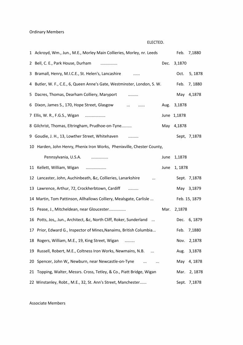
Ordinary Members
ELECTED.
1 Ackroyd, Wm., Jun., M.E., Morley Main Collieries, Morley, nr. Leeds Feb. 7,1880
2 Bell, C. E., Park House, Durham ............... Dec. 3,1870
3 Bramall, Henry, M.I.C.E., St. Helen's, Lancashire ...... Oct. 5, 1878
4 Butler, W. F., C.E., 6, Queen Anne's Gate, Westminster, London, S. W. Feb. 7, 1880
5 Dacres, Thomas, Dearham Colliery, Maryport ......... May 4,1878
6 Dixon, James S., 170, Hope Street, Glasgow ... ...... Aug. 3,1878
7 Ellis, W. R., F.G.S., Wigan .................. June 1,1878
8 Gilchrist, Thomas, Eltringham, Prudhoe-on-Tyne......... May 4,1878
9 Goudie, J. H., 13, Lowther Street, Whitehaven ......... Sept, 7,1878
10 Harden, John Henry, Phenix Iron Works, Phenixville, Chester County,
Pennsylvania, U.S.A. ............... June 1,1878
11 Kellett, William, Wigan .................. June 1, 1878
12 Lancaster, John, Auchinbeath, &c, Collieries, Lanarkshire ... Sept. 7,1878
13 Lawrence, Arthur, 72, Crockherbtown, Cardiff ......... May 3,1879
14 Martin, Tom Pattinson, Allhallows Colliery, Mealsgate, Carlisle ... Feb. 15, 1879
15 Pease, J., Mitcheldean, near Gloucester............... Mar. 2,1878
16 Potts, Jos,, Jun., Architect, &c, North Cliff, Roker, Sunderland ... Dec. 6, 1879
17 Prior, Edward G., Inspector of Mines,Nanaims, British Columbia... Feb. 7,1880
18 Rogers, William, M.E., 19, King Street, Wigan ......... Nov. 2,1878
19 Russell, Robert, M.E., Coltness Iron Works, Newmains, N.B. ... Aug. 3,1878
20 Spencer, John W„ Newburn, near Newcastle-on-Tyne ... ... May 4, 1878
21 Topping, Walter, Messrs. Cross, Tetley, & Co., Piatt Bridge, Wigan Mar. 2, 1878
22 Winstanley, Robt., M.E., 32, St. Ann's Street, Manchester...... Sept. 7,1878
Associate Members

1 Bacon, Arthur H., Murton Colliery, Sunderland ......... Nov. 3,1877
2 Bailes, E. T., Wingate, Ferryhill ............... June 7,1879
3 Barrett, Charles Rollo, Burnhope House, Lanchester ... ... Nov. 7,1874
4 Berkley, R. W., Marley Hill, Colliery, Gateshead ... ...... Feb. 14, 1874
5 Bewick, T. B., Haydon Bridge, Northumberland ......... Mar. 7,1874
6 Brough, Thomas, Seaham Colliery, Seaham Harbour ...... Feb. 1, 1873
7 Brown, M. W., 7, Elswick Park, Newcastle-on-Tyne......... Oct. 7,1871
8 Brown, W. B., Springfield, Wavertree, Liverpool ......... Mar. 2,1878
9 Bruce, John, 2, Framlington Place, Newcastle-on-Tyne ... ... Feb. 14,1874
10 Burnley, E. F., Whitwood Collieries, Normanton ......... April 11, 1874
11 Cabrera, Fidel, c/o H. Kendall & Son, 12, Gt. Winchester St., London Oct. 6,1877
12 Chambers, W. Henry, 15, Victoria Road, Barnsley......... Dec. 2,1871
13 Clark, Robt., Garnant Collieries, Cwmaman, nr. Llanelly, So. Wales Sept. 11, 1875
14 Clough, James, Bedlington Collieries, near Morpeth......... April 5,1873
15 Clovis, Louis, 1, Borough Houses, Gateshead-on-Tyne ...... Feb. 15, 1879
16 Cochrane Ralph D., Hetton Colliery Offices, Fence Houses ... June 1,1878
[xxxvi]
ELECTED.
17 Dalziel, W. G., 2, Pembroke Terrace, Cardiff ......... Sept. 7, 1878
18 Dodd, M., Jun., Heddon Colliery, Wylam-on-Tyne ......... Dec. 4,1875
19 Doyle, John Elyott, B.A. .................. Mar. 1,1879
20 Doyle, Patrick, C.E., F.M.S., F.L.S., M.R.A.S., Municipal Chambers,
Charters Towers, via Townsville, Queensland, Australia ... ... Mar. 1,1879
21 Douglas, M. H., Whitburn Colliery, Sunderland ......... Aug. 2,1879
22 Eden, C. H., Etherley House, Darlington ............ Sept. 13, 1873
23 Edge, John H., Coalport Wire Rope and Chain Works, Shifnal, Salop Sept. 7, 1878
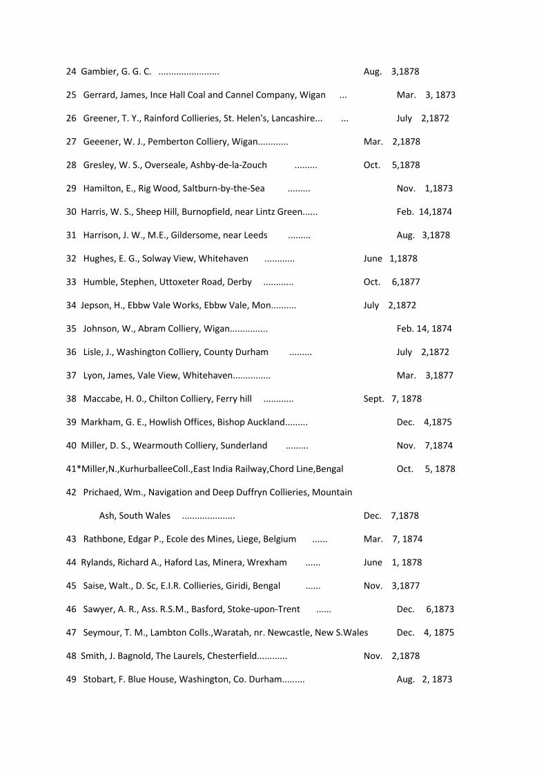
24 Gambier, G. G. C. ........................ Aug. 3,1878
25 Gerrard, James, Ince Hall Coal and Cannel Company, Wigan ... Mar. 3, 1873
26 Greener, T. Y., Rainford Collieries, St. Helen's, Lancashire... ... July 2,1872
27 Geeener, W. J., Pemberton Colliery, Wigan............ Mar. 2,1878
28 Gresley, W. S., Overseale, Ashby-de-la-Zouch ......... Oct. 5,1878
29 Hamilton, E., Rig Wood, Saltburn-by-the-Sea ......... Nov. 1,1873
30 Harris, W. S., Sheep Hill, Burnopfield, near Lintz Green...... Feb. 14,1874
31 Harrison, J. W., M.E., Gildersome, near Leeds ......... Aug. 3,1878
32 Hughes, E. G., Solway View, Whitehaven ............ June 1,1878
33 Humble, Stephen, Uttoxeter Road, Derby ............ Oct. 6,1877
34 Jepson, H., Ebbw Vale Works, Ebbw Vale, Mon.......... July 2,1872
35 Johnson, W., Abram Colliery, Wigan............... Feb. 14, 1874
36 Lisle, J., Washington Colliery, County Durham ......... July 2,1872
37 Lyon, James, Vale View, Whitehaven............... Mar. 3,1877
38 Maccabe, H. 0., Chilton Colliery, Ferry hill ............ Sept. 7, 1878
39 Markham, G. E., Howlish Offices, Bishop Auckland......... Dec. 4,1875
40 Miller, D. S., Wearmouth Colliery, Sunderland ......... Nov. 7,1874
41*Miller,N.,KurhurballeeColl.,East India Railway,Chord Line,Bengal Oct. 5, 1878
42 Prichaed, Wm., Navigation and Deep Duffryn Collieries, Mountain
Ash, South Wales ..................... Dec. 7,1878
43 Rathbone, Edgar P., Ecole des Mines, Liege, Belgium ...... Mar. 7, 1874
44 Rylands, Richard A., Haford Las, Minera, Wrexham ...... June 1, 1878
45 Saise, Walt., D. Sc, E.I.R. Collieries, Giridi, Bengal ...... Nov. 3,1877
46 Sawyer, A. R., Ass. R.S.M., Basford, Stoke-upon-Trent ...... Dec. 6,1873
47 Seymour, T. M., Lambton Colls.,Waratah, nr. Newcastle, New S.Wales Dec. 4, 1875
48 Smith, J. Bagnold, The Laurels, Chesterfield............ Nov. 2,1878
49 Stobart, F. Blue House, Washington, Co. Durham......... Aug. 2, 1873
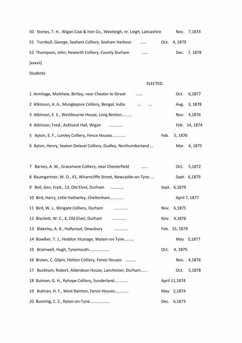
50 Stones, T. H.. Wigan Coal & Iron Co., Westleigh, nr. Leigh, Lancashire Nov. 7,1874
51 Turnbull, George, Seaham Colliery, Seaham Harbour ...... Oct. 4, 1879
52 Thompson, John, Heworth Colliery, County Durham ...... Dec. 7, 1878
[xxxvii]
Students
ELECTED.
1 Armitage, Matthew, Birtley, near Chester-le-Street ...... Oct. 6,1877
2 Atkinson, A. A., Munglepore Colliery, Bengal, India ... ... Aug. 3, 1878
3 Atkinson, E. E., Westbourne House, Long Benton......... Nov. 4,1876
4 Atkinson, Fred., Ackhurst Hall, Wigan ............ Feb. 14, 1874
5 Ayton, E. F., Lumley Colliery, Fence Houses............ Feb. 5, 1876
6 Ayton, Henry, Seaton Delaval Colliery, Dudley, Northumberland ... Mar. 6, 1875
7 Barnes, A. W., Grassmore Colliery, near Chesterfield ...... Oct. 5,1872
8 Baumgartner, W. O., 41, Wharncliffe Street, Newcastle-on-Tyne ... Sept. 6,1879
9 Bell, Geo. Fred., 13, Old Elvet, Durham ............ Sept. 6,1879
10 Bird, Harry, Little Hatherley, Cheltenham............ April 7, 1877
11 Bird, W. J., Wingate Colliery, Durham ............ Nov. 6,1875
12 Blackett, W. C., 6, Old Elvet, Durham ............ Nov. 4,1876
13 Blakeley, A. B., Hollyroyd, Dewsbury ............ Feb. 15, 1879
14 Bowlker, T. J., Heddon Vicarage, Wylam-on-Tyne......... May 5,1877
15 Bramwell, Hugh, Tynemouth.................. Oct. 4, 1879
16 Brown, C. Gilpin, Hetton Colliery, Fence Houses ......... Nov. 4,1876
17 Buckham, Robert, Alderdean House, Lanchester, Durham...... Oct. 5,1878
18 Bulman, G. H., Ryhope Colliery, Sunderland............ April 11,1874
19 Bulman, H. F., West Rainton, Fence Houses............ May 2,1874
20 Bunning, C. Z., Ryton-on-Tyne.................. Dec. 6,1873

21 Caldwell, John S., The Grove, Westhoughton, near Bolton, Lan. ... Nov. 7,1874
22 Candler, T. E., East Lodge, Crook, Darlington ......... May 1,1875
23 Carr, Charles B., Castle Eden Colliery, County Durham ...... May 6, 1876
24 Chapman, Alf. C., Cwmaman Colliery, near Aberdare, South Wales Oct. 4, 1879
25 Child, H., Whitkirk, Leeds .................. Feb. 15, 1879
26 Cobbold, C. H., San Valentino, Abruzzo, Citenone, Italy ...... May 3,1873
27 Cockburn, W. C., 8, Summerhill Grove, Newcastle-on-Tyne...... July 2,1872
28 Cox, L. Clifford, Ravenstone, near Ashby-de-la-Zouch ...... April 1,1876
29 Craig, Ernest, Silksworth Colliery, near Sunderland ...... Nov. 3,1877
30 Crawford, T. W., Peases' West Collieries, Crook, by Darlington ... Dec. 4, 1875
31 Crone, F. E., Killingworth House, near Newcastle ......... Sept. 2, 1876
32 Davidson, C. C., Ore Bank House, Bigrigg, via Carnforth, Cumberland Nov. 4, 1876
33 Davis, Kenneth M., Towneley and Stella Collieries, Ryton-on-Tyne April 5, 1879
34 Depledge, M. F., Satley Vicarage, Darlington ......... April 7,1877
35 Donkin, Wm., Usworth Colliery, Washington Station, Co. Durham ... Sept. 2,1876
36 Dorman, Frank, The Palace, Maidstone, Kent ......... May 1,1875
37 Douglas, Arthur Stanley, Harton Colliery, near South Shields ... June 1,1878
38 Dowson, W. G., Belle Vue House, Escomb, near Bishop Auckland ... Mar. 2, 1878
39 Dunn, A. F., Poynton, Stockport, Cheshire ............ June 2, 1877
40 Durnford, H. St. John, Wharncliffe Silkstone Coll., Wortley, Sheffield June 2,1877
[xxxviii]
ELECTED.
41 Edge, J. C, Ince Hall Coal and Cannel Company, Limited, Wigan ... Dec. 5, 1874
42 Evans, David L., Goldtops, Newport, Monmouthshire ...... May 4, 1878
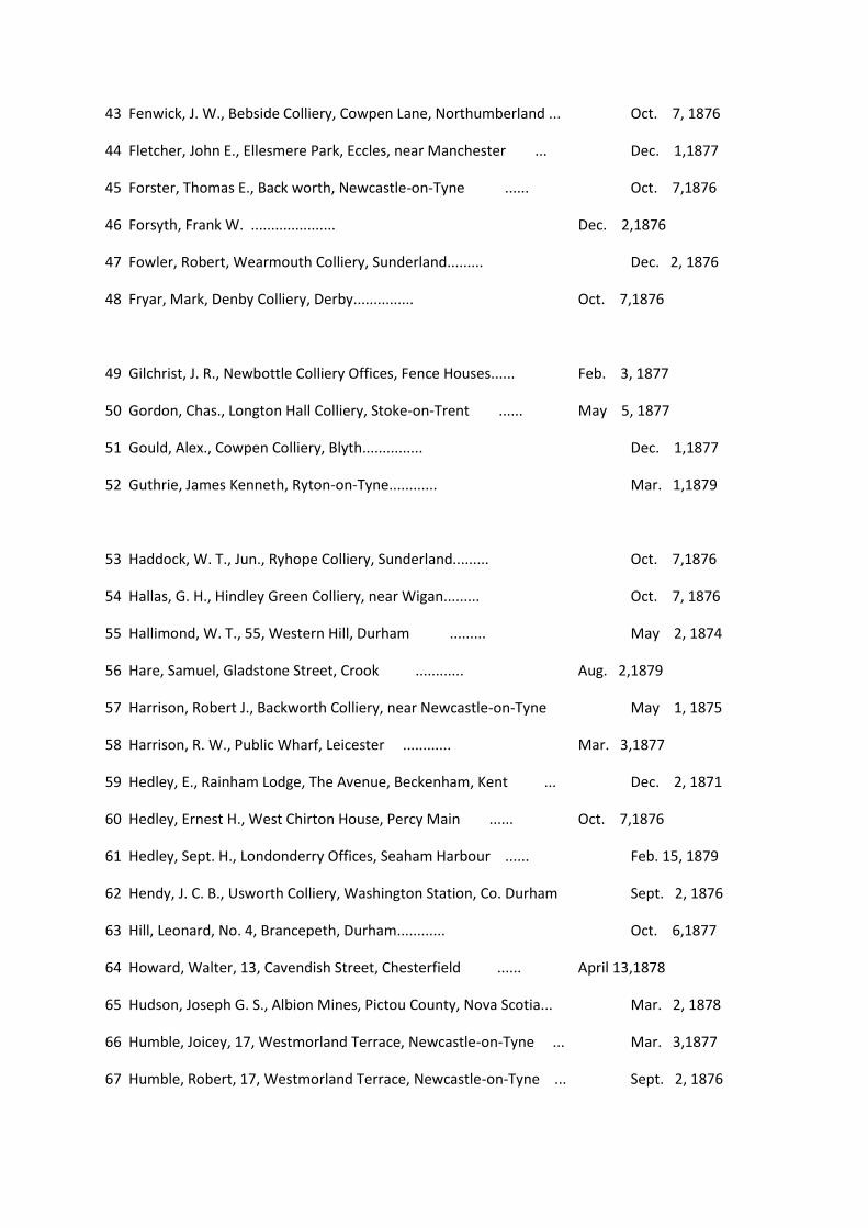
43 Fenwick, J. W., Bebside Colliery, Cowpen Lane, Northumberland ... Oct. 7, 1876
44 Fletcher, John E., Ellesmere Park, Eccles, near Manchester ... Dec. 1,1877
45 Forster, Thomas E., Back worth, Newcastle-on-Tyne ...... Oct. 7,1876
46 Forsyth, Frank W. ..................... Dec. 2,1876
47 Fowler, Robert, Wearmouth Colliery, Sunderland......... Dec. 2, 1876
48 Fryar, Mark, Denby Colliery, Derby............... Oct. 7,1876
49 Gilchrist, J. R., Newbottle Colliery Offices, Fence Houses...... Feb. 3, 1877
50 Gordon, Chas., Longton Hall Colliery, Stoke-on-Trent ...... May 5, 1877
51 Gould, Alex., Cowpen Colliery, Blyth............... Dec. 1,1877
52 Guthrie, James Kenneth, Ryton-on-Tyne............ Mar. 1,1879
53 Haddock, W. T., Jun., Ryhope Colliery, Sunderland......... Oct. 7,1876
54 Hallas, G. H., Hindley Green Colliery, near Wigan......... Oct. 7, 1876
55 Hallimond, W. T., 55, Western Hill, Durham ......... May 2, 1874
56 Hare, Samuel, Gladstone Street, Crook ............ Aug. 2,1879
57 Harrison, Robert J., Backworth Colliery, near Newcastle-on-Tyne May 1, 1875
58 Harrison, R. W., Public Wharf, Leicester ............ Mar. 3,1877
59 Hedley, E., Rainham Lodge, The Avenue, Beckenham, Kent ... Dec. 2, 1871
60 Hedley, Ernest H., West Chirton House, Percy Main ...... Oct. 7,1876
61 Hedley, Sept. H., Londonderry Offices, Seaham Harbour ...... Feb. 15, 1879
62 Hendy, J. C. B., Usworth Colliery, Washington Station, Co. Durham Sept. 2, 1876
63 Hill, Leonard, No. 4, Brancepeth, Durham............ Oct. 6,1877
64 Howard, Walter, 13, Cavendish Street, Chesterfield ...... April 13,1878
65 Hudson, Joseph G. S., Albion Mines, Pictou County, Nova Scotia... Mar. 2, 1878
66 Humble, Joicey, 17, Westmorland Terrace, Newcastle-on-Tyne ... Mar. 3,1877
67 Humble, Robert, 17, Westmorland Terrace, Newcastle-on-Tyne ... Sept. 2, 1876
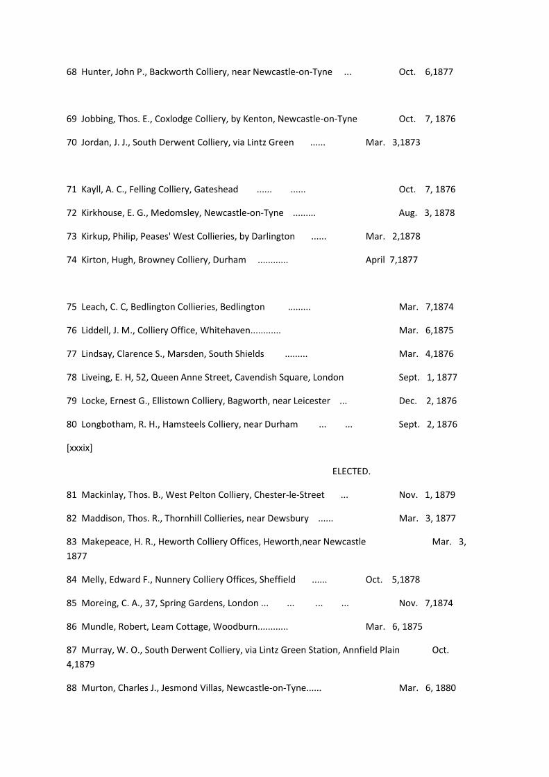
68 Hunter, John P., Backworth Colliery, near Newcastle-on-Tyne ... Oct. 6,1877
69 Jobbing, Thos. E., Coxlodge Colliery, by Kenton, Newcastle-on-Tyne Oct. 7, 1876
70 Jordan, J. J., South Derwent Colliery, via Lintz Green ...... Mar. 3,1873
71 Kayll, A. C., Felling Colliery, Gateshead ...... ...... Oct. 7, 1876
72 Kirkhouse, E. G., Medomsley, Newcastle-on-Tyne ......... Aug. 3, 1878
73 Kirkup, Philip, Peases' West Collieries, by Darlington ...... Mar. 2,1878
74 Kirton, Hugh, Browney Colliery, Durham ............ April 7,1877
75 Leach, C. C, Bedlington Collieries, Bedlington ......... Mar. 7,1874
76 Liddell, J. M., Colliery Office, Whitehaven............ Mar. 6,1875
77 Lindsay, Clarence S., Marsden, South Shields ......... Mar. 4,1876
78 Liveing, E. H, 52, Queen Anne Street, Cavendish Square, London Sept. 1, 1877
79 Locke, Ernest G., Ellistown Colliery, Bagworth, near Leicester ... Dec. 2, 1876
80 Longbotham, R. H., Hamsteels Colliery, near Durham ... ... Sept. 2, 1876
[xxxix]
ELECTED.
81 Mackinlay, Thos. B., West Pelton Colliery, Chester-le-Street ... Nov. 1, 1879
82 Maddison, Thos. R., Thornhill Collieries, near Dewsbury ...... Mar. 3, 1877
83 Makepeace, H. R., Heworth Colliery Offices, Heworth,near Newcastle Mar. 3,
1877
84 Melly, Edward F., Nunnery Colliery Offices, Sheffield ...... Oct. 5,1878
85 Moreing, C. A., 37, Spring Gardens, London ... ... ... ... Nov. 7,1874
86 Mundle, Robert, Leam Cottage, Woodburn............ Mar. 6, 1875
87 Murray, W. O., South Derwent Colliery, via Lintz Green Station, Annfield Plain Oct.
4,1879
88 Murton, Charles J., Jesmond Villas, Newcastle-on-Tyne...... Mar. 6, 1880
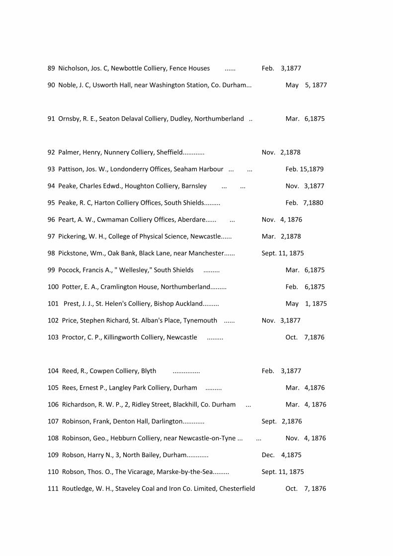
89 Nicholson, Jos. C, Newbottle Colliery, Fence Houses ...... Feb. 3,1877
90 Noble, J. C, Usworth Hall, near Washington Station, Co. Durham... May 5, 1877
91 Ornsby, R. E., Seaton Delaval Colliery, Dudley, Northumberland .. Mar. 6,1875
92 Palmer, Henry, Nunnery Colliery, Sheffield............ Nov. 2,1878
93 Pattison, Jos. W., Londonderry Offices, Seaham Harbour ... ... Feb. 15,1879
94 Peake, Charles Edwd., Houghton Colliery, Barnsley ... ... Nov. 3,1877
95 Peake, R. C, Harton Colliery Offices, South Shields......... Feb. 7,1880
96 Peart, A. W., Cwmaman Colliery Offices, Aberdare...... ... Nov. 4, 1876
97 Pickering, W. H., College of Physical Science, Newcastle...... Mar. 2,1878
98 Pickstone, Wm., Oak Bank, Black Lane, near Manchester...... Sept. 11, 1875
99 Pocock, Francis A., " Wellesley," South Shields ......... Mar. 6,1875
100 Potter, E. A., Cramlington House, Northumberland......... Feb. 6,1875
101 Prest, J. J., St. Helen's Colliery, Bishop Auckland......... May 1, 1875
102 Price, Stephen Richard, St. Alban's Place, Tynemouth ...... Nov. 3,1877
103 Proctor, C. P., Killingworth Colliery, Newcastle ......... Oct. 7,1876
104 Reed, R., Cowpen Colliery, Blyth ............... Feb. 3,1877
105 Rees, Ernest P., Langley Park Colliery, Durham ......... Mar. 4,1876
106 Richardson, R. W. P., 2, Ridley Street, Blackhill, Co. Durham ... Mar. 4, 1876
107 Robinson, Frank, Denton Hall, Darlington............ Sept. 2,1876
108 Robinson, Geo., Hebburn Colliery, near Newcastle-on-Tyne ... ... Nov. 4, 1876
109 Robson, Harry N., 3, North Bailey, Durham............ Dec. 4,1875
110 Robson, Thos. O., The Vicarage, Marske-by-the-Sea......... Sept. 11, 1875
111 Routledge, W. H., Staveley Coal and Iron Co. Limited, Chesterfield Oct. 7, 1876

112 Scarth, R, W., Stanghow House, Stanghow, near Guisbro' ... ... Dec. 4,1875
113 Schier, H. C, East Hetton Colliery Offices, Coxhoe, Co. Durham ... Dec. 4, 1875
114 Scott, Alex., Lofthouse Colliery, Limited, Wakefield ...... Mar. 2,1878
115 Scott, Walter, Cornsay Colliery, Lanchester... ... ... ... Sept. 6, 1879
116 Scott, Wm., Brancepeth Colliery Offices, Willington, Co. Durham ... Mar. 4, 1876
117 Smith, T. F., Jun., Cinderford Villas, near Newnham, Gloucestershire May 5, 1877
118 Smith, Thos., Leadgate, County Durham ............ Feb. 15, 1879
119 Southern, E. O., 5, Fenwick Terrace, Jesmond, Newcastle...... Dec. 5,1874
120 Southern, W. J. ........................ Aug. 1,1874
121 Spence, R. F., Cramlington .................. Nov. 2,1878
122 Stoker, Arthur P., Birtley, near Chester-le-Street......... Oct. 6,1877
[xl]
ELECTED.
123 Telford, W. H., Cramlington Colliery, Northumberland ...... Oct. 3,1874
121 Thompson, William ..................... May 2,1874
125 Todd, John T., Hetton-le-Hole, Fence Houses............ Nov. 4,1876
126 Todner, W. J. S., 6, George's Road, Elswick, Newcastle-on-Tyne ... Sept. 6, 1879
127 Topham, Edward C, Houghton Main Colliery, Darfield, near Barnsley Nov.
3,1877
128 Tucker, A. W., Turk's Head Brewery, Gateshead ......... Dec. 2,1876
129 Vernes, Amidee, 8, Claremont Place, Gateshead ......... May 4,1878
130 Walker, F. W., Aldbro', Darlington............... Sept. 2,1876
131 Walker, Smart, Ryhope Colliery, near Sunderland......... Dec. 4,1875
132 Walton, J. C., Heworth Colliery, near Newcastle-on-Tyne...... Nov. 7,1874
133 White, C. E., Hebburn Colliery, near Newcastle-on-Tyne ...... Nov. 4,1876
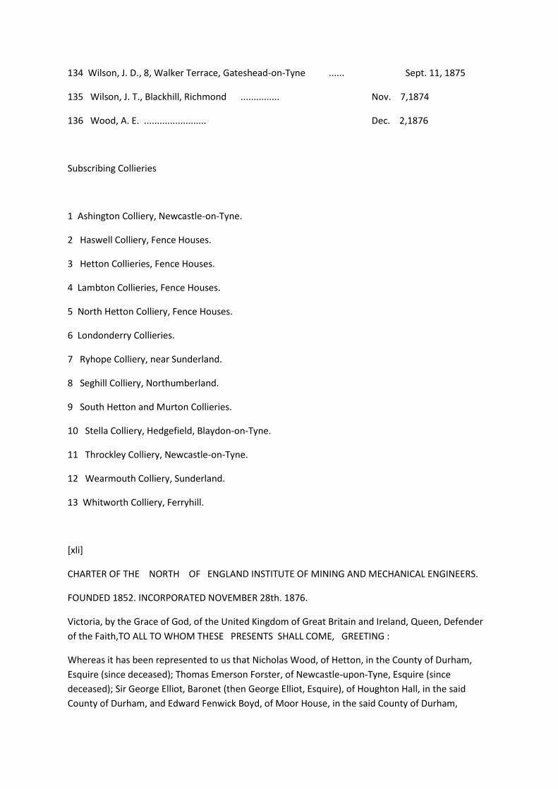
134 Wilson, J. D., 8, Walker Terrace, Gateshead-on-Tyne ...... Sept. 11, 1875
135 Wilson, J. T., Blackhill, Richmond ............... Nov. 7,1874
136 Wood, A. E. ........................ Dec. 2,1876
Subscribing Collieries
1 Ashington Colliery, Newcastle-on-Tyne.
2 Haswell Colliery, Fence Houses.
3 Hetton Collieries, Fence Houses.
4 Lambton Collieries, Fence Houses.
5 North Hetton Colliery, Fence Houses.
6 Londonderry Collieries.
7 Ryhope Colliery, near Sunderland.
8 Seghill Colliery, Northumberland.
9 South Hetton and Murton Collieries.
10 Stella Colliery, Hedgefield, Blaydon-on-Tyne.
11 Throckley Colliery, Newcastle-on-Tyne.
12 Wearmouth Colliery, Sunderland.
13 Whitworth Colliery, Ferryhill.
[xli]
CHARTER OF THE NORTH OF ENGLAND INSTITUTE OF MINING AND MECHANICAL ENGINEERS.
FOUNDED 1852. INCORPORATED NOVEMBER 28th. 1876.
Victoria, by the Grace of God, of the United Kingdom of Great Britain and Ireland, Queen, Defender
of the Faith,TO ALL TO WHOM THESE PRESENTS SHALL COME, GREETING :
Whereas it has been represented to us that Nicholas Wood, of Hetton, in the County of Durham,
Esquire (since deceased); Thomas Emerson Forster, of Newcastle-upon-Tyne, Esquire (since
deceased); Sir George Elliot, Baronet (then George Elliot, Esquire), of Houghton Hall, in the said
County of Durham, and Edward Fenwick Boyd, of Moor House, in the said County of Durham,
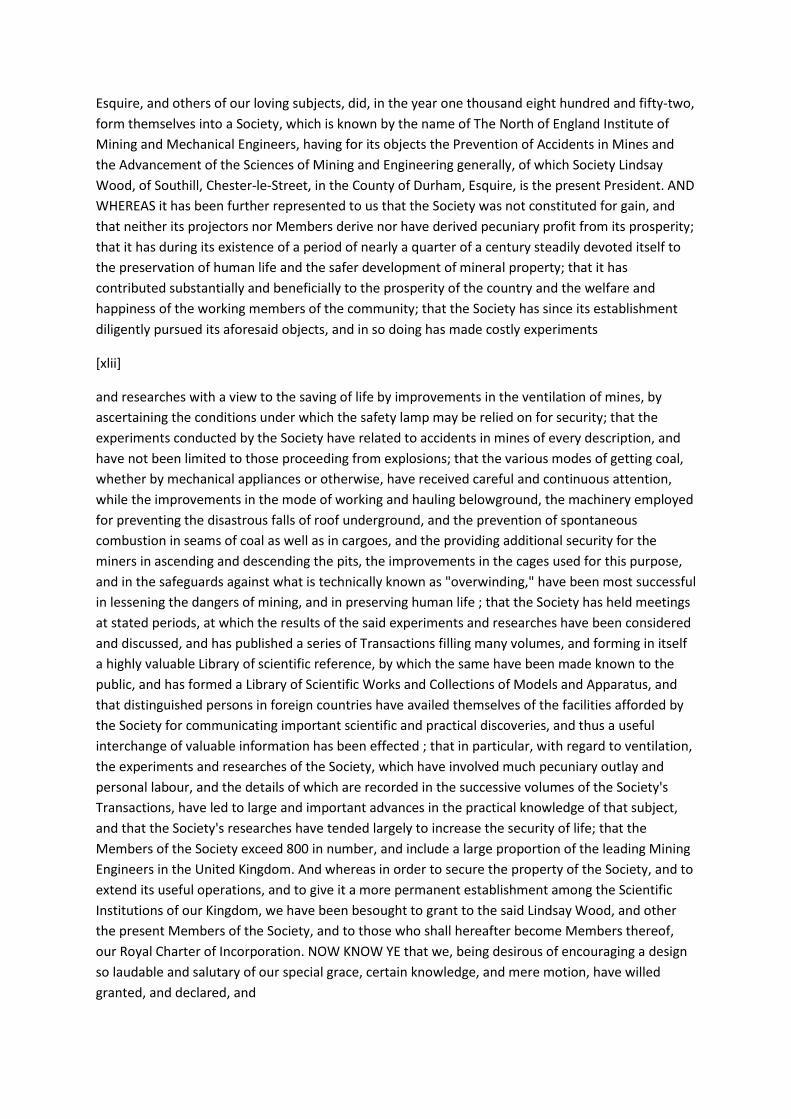
Esquire, and others of our loving subjects, did, in the year one thousand eight hundred and fifty-two,
form themselves into a Society, which is known by the name of The North of England Institute of
Mining and Mechanical Engineers, having for its objects the Prevention of Accidents in Mines and
the Advancement of the Sciences of Mining and Engineering generally, of which Society Lindsay
Wood, of Southill, Chester-le-Street, in the County of Durham, Esquire, is the present President. AND
WHEREAS it has been further represented to us that the Society was not constituted for gain, and
that neither its projectors nor Members derive nor have derived pecuniary profit from its prosperity;
that it has during its existence of a period of nearly a quarter of a century steadily devoted itself to
the preservation of human life and the safer development of mineral property; that it has
contributed substantially and beneficially to the prosperity of the country and the welfare and
happiness of the working members of the community; that the Society has since its establishment
diligently pursued its aforesaid objects, and in so doing has made costly experiments
[xlii]
and researches with a view to the saving of life by improvements in the ventilation of mines, by
ascertaining the conditions under which the safety lamp may be relied on for security; that the
experiments conducted by the Society have related to accidents in mines of every description, and
have not been limited to those proceeding from explosions; that the various modes of getting coal,
whether by mechanical appliances or otherwise, have received careful and continuous attention,
while the improvements in the mode of working and hauling belowground, the machinery employed
for preventing the disastrous falls of roof underground, and the prevention of spontaneous
combustion in seams of coal as well as in cargoes, and the providing additional security for the
miners in ascending and descending the pits, the improvements in the cages used for this purpose,
and in the safeguards against what is technically known as "overwinding," have been most successful
in lessening the dangers of mining, and in preserving human life ; that the Society has held meetings
at stated periods, at which the results of the said experiments and researches have been considered
and discussed, and has published a series of Transactions filling many volumes, and forming in itself
a highly valuable Library of scientific reference, by which the same have been made known to the
public, and has formed a Library of Scientific Works and Collections of Models and Apparatus, and
that distinguished persons in foreign countries have availed themselves of the facilities afforded by
the Society for communicating important scientific and practical discoveries, and thus a useful
interchange of valuable information has been effected ; that in particular, with regard to ventilation,
the experiments and researches of the Society, which have involved much pecuniary outlay and
personal labour, and the details of which are recorded in the successive volumes of the Society's
Transactions, have led to large and important advances in the practical knowledge of that subject,
and that the Society's researches have tended largely to increase the security of life; that the
Members of the Society exceed 800 in number, and include a large proportion of the leading Mining
Engineers in the United Kingdom. And whereas in order to secure the property of the Society, and to
extend its useful operations, and to give it a more permanent establishment among the Scientific
Institutions of our Kingdom, we have been besought to grant to the said Lindsay Wood, and other
the present Members of the Society, and to those who shall hereafter become Members thereof,
our Royal Charter of Incorporation. NOW KNOW YE that we, being desirous of encouraging a design
so laudable and salutary of our special grace, certain knowledge, and mere motion, have willed
granted, and declared, and

[xliii]
do, by these presents, for us, our heirs, and successors, will, grant, and declare, that the said Lindsay
Wood, and such others of our loving subjects as are now Members of the said Society, and such
others as shall from time to time hereafter become Members thereof, according to such Bye-laws as
shall be made as hereinafter mentioned, and their successors, shall for ever hereafter be, by virtue
of these presents, one body, politic and corporate, by the name of "The North of England Institute of
Mining and Mechanical Engineers," and by the name aforesaid shall have perpetual succession and a
Common Seal, with full power and authority to alter, vary, break, and renew the same at their
discretion, and by the same name to sue and be sued, implead and be impleaded, answer and be
answered unto, in every Court of us, our heirs and successors, and be for ever able and capable in
the law to purchase, acquire, receive, possess, hold, and enjoy to them and their successors any
goods and chattels whatsoever, and also be able and capable in the law (notwithstanding the
statutes and mortmain) to purchase, acquire, possess, hold and enjoy to them and their successors a
hall or house, and any such other lands, tenements, or hereditaments whatsoever, as they may
deem requisite for the purposes of the Society, the yearly value of which, including the site of the
said hall or house, shall not exceed in the whole the sum of three thousand pounds, computing the
same respectfully at the rack rent which might have been had or gotten for the same respectfully at
the time of the purchase or acquisition thereof. And we do hereby grant our especial licence and
authority unto all and every person and persons and bodies politic and corporate, otherwise
competent, to grant, sell, alien, convey or devise in mortmain unto and to the use of the said Society
and their successors, any lands, tenements, or hereditaments not exceeding with the lands,
tenements or hereditaments so purchased or previously acquired such annual value as aforesaid,
and also any moneys, stocks, securities, and other personal estate to be laid out and disposed of in
the purchase of any lands, tenements, or hereditaments not exceeding the like annual value. And we
further will, grant, and declare, that the said Society shall have full power and authority, from time
to time, to sell, grant, demise, exchange and dispose of absolutely, or by way of mortgage, or
otherwise, any of the lands, tenements, hereditaments and possessions, wherein they have any
estate or interest, or which they shall acquire as aforesaid, but that no sale, mortgage, or other
disposition of any lands, tenements, or hereditaments of the Society shall be made, except with the
approbation and concurrence of a General Meeting. And our will and pleasure is, and we further
grant and declare that for the better rule
[xliv]
and government of the Society, and the direction and management of the concerns thereof, there
shall be a Council of the Society, to be appointed from among the Members thereof, and to include
the President and the Vice-Presidents, and such other office-bearers or past office-bearers as may
be directed by such Bye-laws as hereinafter mentioned, but so that the Council, including all ex-
officio Members thereof, shall consist of not more than forty or less than twelve Members, and that
the Vice-Presidents shall be not more than six or less than two in number. And we do hereby further
will and declare that the said Lindsay Wood shall be the first President of the Society, and the
persons now being the Vice-Presidents, and the Treasurer and Secretary, shall be the first Vice-
Presidents, and the first Treasurer and Secretary, and the persons now being the Members of the
Council shall be the first Members of the Council of the Society, and that they respectfully shall
continue such until the first election shall be made at a General Meeting in pursuance of these

presents. AND WE DO HEREBY FURTHER will and declare that, subject to the powers by these
presents vested in the General Meetings of the Society, the Council shall have the management of
the Society, and of the income and property thereof, including the appointment of officers and
servants, the definition of their duties, and the removal of any of such officers and servants, and
generally may do all such acts and deeds as they shall deem necessary or fitting to be done, in order
to carry into full operation and effect the objects and purposes of the Society, but so always that the
same be not inconsistent with, or repugnant to, any of the provisions of this our Charter, or the Laws
of our Realm, or any Bye-law of the Society in force for the time being. AND WE DO HEREBY
FURTHER will and declare that at any General Meeting of the Society, it shall be lawful for the
Society, subject as hereinafter mentioned, to make such Bye-laws as to them shall seem necessary
or proper for the regulation and good government of the Society, and of the Members and affairs
thereof, and generally for carrying the objects of the Society into full and complete effect, and
particularly (and without its being intended hereby to prejudice the foregoing generality), to make
Bye-laws for all or any of the purposes hereinafter mentioned, that is to say: for fixing the number of
Vice-Presidents, and the number of Members of which the Council shall consist, and the manner of
electing the President and Vice-Presidents, and other Members of the Council, and the period of
their continuance in office, and the manner and time of supplying any vacancy therein; and for
regulating the times at which General Meetings of the Society and Meetings of the Council shall be
held, and for convening the same and regulating the proceedings thereat, and
[xlv]
for regulating the manner of admitting persons to be Members of the Society, and of removing or
expelling Members from the Society, and for imposing reasonable fines or penalties for non-
performance of any such Bye-laws, or for disobedience thereto, and from time to time to annul,
alter, or change any such Bye-laws so always that all Bye-laws to be made as aforesaid be not
repugnant to these presents, or to any of the laws of our Realm. AND WE DO FURTHER will and
declare that the present Rules and Regulations of the Society, so far as they are not inconsistent with
these presents, shall continue in force, and be deemed the Bye-laws of the Society until the same
shall be altered by a General Meeting, provided always that the present Rules and Regulations of the
Society and any future Bye-laws of the Society so to be made as aforesaid shall have no force or
effect whatsoever until the same shall have been approved in writing by our Secretary of State for
the Home Department. IN WITMESS WHEREOF WE HAVE CAUSED THESE OUR LETTERS TO BE MADE
PATENT.
Witness Ourself at our Palace, at Westminster, this 28th day of November, in the fortieth year of
our reign.
By Her Majesty's Command.
CARDEW.
[xlvi]
blank page
[xlvii]
THE NORTH OF ENGLAND INSTITUTE OF MINING AND MECHANICAL ENGINEERS.
BYE-LAWS PASSED AT A GENERAL MEETING ON THE 16th JUNE, 1877.
1.—The members of the North of England Institute of Mining and Mechanical Engineers shall consist
of four classes, viz.:—Original Members, Ordinary Members, Associate Members, and Honorary
Members, with a class of Students attached.
2.—Original Members shall be those who were Ordinary Members on the 1st of August, 1877.
8.—Ordinary Members.—Every candidate for admission into the class of Ordinary Members, or for
transfer into that class, shall come within the following conditions :—He shall be more than twenty-
eight years of age, have been regularly educated as a Mining or Mechanical Engineer, or in some
other recognised branch of Engineering, according to the usual routine of pupilage, and have had
subsequent employment for at least five years in some responsible situation as an Engineer, or if he
has not undergone the usual routine of pupilage, he must have practised on his own account in the
profession of an Engineer for at least five years, and have acquired a considerable degree of
eminence in the same.
4.—Associate Members shall be persons practising as Mining or Mechanical Engineers, or in some
other recognised branch of Engineering, and other persons connected with or interested in Mining
or Engineering.
5.—Honorary Members shall be persons who have distinguished themselves by their literary or
scientific attainments, or who have made important communications to the Society.
6.—Students shall be persons who are qualifying themselves for the profession of Mining or
Mechanical Engineering, or some other of the recognised branches of Engineering, and such persons
may continue Students until they attain the age of twenty-three years.
[xlviii]
7.—The annual subscription of each Original Member, and of each Ordinary Member who was a
Student on the 1st of August, 1877, shall be £2 2s., of each Ordinary Member (except as last
mentioned) £3 3s., of each Associate Member £2 2s., and of each Student £1 1s., payable in
advance, and shall be considered due on election, and afterwards on the first Saturday in August of
each year.
8.—Any Member may, at any time, compound for all future subscriptions by a payment of £25,
where the annual subscription is £3 3s., and by a payment of £20 where the annual subscription is
£2 2s. All persons so compounding shall be Original, Ordinary, or Associate Members for life, as the
case may be ; but any Associate Member for life who may afterwards desire to become an Ordinary
Member for life, may do so, after being elected in the manner described in Bye-law 13, and on
payment of the further sum of £5.
9.—Owners of Collieries, Engineers, Manufacturers, and Employers of labour generally, may
subscribe annually to the funds of the Institute, and each such subscriber of £2 2s. annually shall be
entitled to a ticket to admit two persons to the rooms, library, meetings, lectures, and public
proceedings of the Society; and for every additional £2 2s., subscribed annually, two other persons

shall be admissible up to the number of ten persons ; and each such Subscriber shall also be entitled
for each £2 2s. subscription to have a copy of the Proceedings of the Institute sent to him.
10.—In case any Member, who has been long distinguished in his professional career, becomes
unable, from ill-health, advanced age, or other sufficient cause, to carry on a lucrative practice, the
Council may, on the report of a Sub-Committee appointed for that purpose, if they find good reason
for the remission of the annual subscription, so remit it. They may also remit any arrears which are
due from a member, or they may accept from him a collection of books, or drawings, or models, or
other contributions, in lieu of the composition mentioned in Bye-law 8, and may thereupon
constitute him a Life Member, or permit him to resume his former rank in the Institute.
11.—Persons desirous of becoming Ordinary Members shall be proposed and recommended,
according to the Form A in the Appendix, in which form the name, usual residence, and
qualifications of the candidate shall be distinctly specified. This form must be signed by the proposer
and at least five other Members certifying a personal knowledge of the candidate. The proposal so
made being delivered to the Secretary, shall be submitted to the Council, who on approving the
qualifications shall determine if the candidate is to be presented for ballot, and if it is so deter-
[xlix]
mined, the Chairman of the Council shall sign such approbation. The same shall be read at the next
Ordinary General Meeting, and afterwards be placed in some conspicuous situation until the
following Ordinary General Meeting, when the candidate shall be balloted for.
12.—Persons desirous of being admitted into the Institute as Associate Members, or Students, shall
be proposed by three Members; Honorary Members shall be proposed by at least five Members,
and shall in addition be recommended by the Council, who shall also have the power of defining the
time during which, and the circumstances under which, they shall be Honorary Members. The
nomination shall be in writing, and signed by the proposers (according to the Form B in the
Appendix), and shall be submitted to the first Ordinary General Meeting after the date thereof. The
name of the person proposed shall be exhibited in the Society's room until the next Ordinary
General Meeting, when the candidate shall be balloted for.
13.—Associate Members or Students, desirous of becoming Ordinary Members, shall be proposed
and recommended according to the Form C in the Appendix, in which form the name, usual
residence, and qualifications of the candidate shall be distinctly specified. This form must certify a
personal knowledge of the candidate, and be signed by the proposer and at least two other
Members, and the proposal shall then be treated in the manner described in Bye-law 11. Students
may become Associate Members at any time after attaining the age of twenty-three on payment of
an Associate Member's subscription.
14.—The balloting shall be conducted in the following manner:— Each Member attending the
Meeting at which a ballot is to take place shall be supplied (on demand) with a list of the names of
the persons to be balloted for, according to the Form D in the Appendix, and shall strike out the
names of such candidates as he desires shall not be elected, and return the list to the scrutineers
appointed by the presiding Chairman for the purpose, and such scrutineers shall examine the lists so

returned, and inform the meeting what elections have been made. No candidate shall be elected
unless he secures the votes of two-thirds of the Members voting.
15.—Notice of election shall be sent to every person within one week after his election, according to
the Form E in the Appendix, enclosing at the same time a copy of Form F, which shall be returned by
the person elected, signed, and accompanied with the amount of his annual subscription, or life
composition, within two months from the date of such election, which otherwise should become
void.
[l]
16.—Every Ordinary Member elected having signed a declaration in the Form F, and having likewise
made the proper payment, shall receive a certificate of his election.
17.—Any person whose subscription is two years in arrear shall be reported to the Council, who shall
direct application to be made for it, according to the Form G in the Appendix, and in the event of its
continuing one month in arrear after such application, the Council shall have the power, after
remonstrance by letter, according to the Form H in the Appendix, of declaring that the defaulter has
ceased to be a member.
18.—In case the expulsion of any person shall be judged expedient by ten or more Members, and
they think fit to draw up and sign a proposal requiring such expulsion, the same being delivered to
the Secretary, shall be by him laid before the Council for consideration. If the Council, after due
inquiry, do not find reason to concur in the proposal, no entry thereof shall be made in any minutes,
nor shall any public discussion thereon be permitted, unless by requisition signed by one-half the
Members of the Institute ; but if the Council do find good reason for the proposed expulsion, they
shall direct the Secretary to address a letter, according to the Form I in the Appendix, to the person
proposed to be expelled, advising him to withdraw from the Institute. If that advice be followed, no
entry on the minutes nor any public discussion on the subject shall be permitted ; but if that advice
be not followed, nor an explanation given which is satisfactory to the Council, they shall call a
General Meeting for the purpose of deciding on the question of expulsion ; and if a majority of the
persons present at such Meeting (provided the number so present be not less than forty) vote that
such person be expelled, the Chairman of that Meeting shall declare the same accordingly, and the
Secretary shall communicate the same to the person, according to the Form J in the Appendix.
19.—The Officers of the Institute, other than the Treasurer and the Secretary, shall be elected from
the Original, Ordinary and Associate Members, and shall consist of a President, six Vice-Presidents,
and eighteen Councillors, who,, with the Treasurer and the Secretary (if Members of the Institute)
shall constitute the Council. The President, Vice-Presidents, and Councillors shall be elected at the
Annual Meeting in August (except in cases of vacancies) and shall be eligible for re-election, with the
exception of any President or Vice-President who may have held office for the three immediately
preceding years, and such six Councillors as may have attended the fewest Council Meetings during
the past
[li]
year; but such Members shall be eligible for re-election after being one year out of office.

20.—The Treasurer and the Secretary shall be appointed by the Council, and shall be removable by
the Council, subject to appeal to a General Meeting. One and the same person may hold both
these offices.
21.—Each Original, Ordinary, and Associate Member shall be at liberty to nominate in writing, and
send to the Secretary not less than eight days prior to the Ordinary General Meeting in June, a list,
duly signed, of Members suitable to fill the offices of President, Vice-Presidents, and Members of
Council, for the ensuing year. The Council shall prepare a list of the persons so nominated, together
with the names of the Officers for the current year eligible for re-election, and of such other
Members as they deem suitable for the various offices. Such list shall comprise the names of not less
than thirty. The list so prepared by the Council shall be submitted to the General Meeting in June,
and shall be the balloting list for the annual election in August. (See Form K in the Appendix.) A copy
of this list shall be posted at least seven days previous to the Annual Meeting, to every Original,
Ordinary, and Associate Member; who may erase any name or names from the list, and substitute
the name or names of any other person or persons eligible for each respective office; but the
number of persons on the list, after such erasure or substitution, must not exceed the number to be
elected to the respective offices. Papers which do not accord with these directions shall be rejected
by the scrutineers. The Votes for any Members who may not be elected President or Vice-Presidents
shall count for them as Members of the Council. The Chairman shall appoint four scrutineers, who
shall receive the balloting papers, and, after making the necessary scrutiny, destroy the same, and
sign and hand to the Chairman a list of the elected Officers. The balloting papers may be returned
through the post, addressed to the Secretary, or be handed to him, or to the Chairman of the
Meeting, so as to be received before the appointment of the scrutineers for the election of Officers.
22.—In case of the decease or resignation of any Officer or Officers, the Council, if they deem it
requisite that the vacancy shall be filled up, shall present to the next Ordinary General Meeting a list
of persons whom they nominate as suitable for the vacant offices, and a new Officer or Officers shall
be elected at the succeeding Ordinary General Meeting.
23.—The President shall take the chair at all meetings of the Institute, the Council, and Committees,
at which he is present (he being ex-officio a member of all), and shall regulate and keep order in the
proceedings.
[lii]
24.—In the absence of the President, it shall be the duty of the senior Vice-President present to
preside at the meetings of the Institute, to keep order, and to regulate the proceedings. In case of
the absence of the President and of all the Vice-Presidents, the meeting may elect any Member of
Council, or in case of their absence, any Member present, to take the chair at the meeting.
25.—The Council may appoint Committees for the purpose of transacting any particular business, or
of investigating specific subjects connected with the objects of the Institute. Such Committees shall
report to the Council, who shall act thereon as they see occasion.
26.—The Treasurer and the Secretary shall act under the direction and control of the Council, by
which body their duties shall from time to time be defined.

27.—The Funds of the Society shall be deposited in the hands of the Treasurer, and shall be
disbursed or invested by him according to the direction of the Council.
28.—The Copyright of all papers communicated to, and accepted for printing by the Council, and
printed within twelve months, shall become vested in the Institute, and such communications shall
not be published for sale or otherwise, without the written permission of the Council.
29.—An Ordinary General Meeting shall be held on the first Saturday of every month (except
January and July) at two o'clock, unless otherwise determined by the Council; and the Ordinary
General Meeting in the month of August shall be the Annual Meeting, at which a report of the
proceedings, and an abstract of the accounts of the previous year, shall be'presented by the Council.
A Special General Meeting shall be called whenever the Council may think fit, and also on a
requisition to the Council, signed by ten or more Members. The business of a Special Meeting shall
be confined to that specified in the notice convening it.
30.—At meetings of the Council, five shall be a quorum. The minutes of the Council's proceedings
shall be at all times open to the inspection of the Members.
81.—All Past-Presidents shall be ex-officio Members of the Council so long as they continue
Members of the Institute, and Vice-Presidents who have not been re-elected or have become
ineligible from having held office for three consecutive years, shall be ex-officio Members of the
Council for the following year.
32.—Every question, not otherwise provided for, which shall come before any Meeting, shall be
decided by the votes of the majority of the Original, Ordinary, and Associate Members then present.
[liii]
33.—All papers shall be sent for the approval of the Council at least twelve days before a General
Meeting, and after approval, shall be read before the Institute. The Council shall also direct whether
any paper read before the Institute shall be printed in the Transactions, and notice shall be given to
the writer within one month after it has been read, whether it is to be printed or not.
34.—All proofs of reports of discussions, forwarded to Members for correction, must be returned to
the Secretary within seven days from the date of their receipt, otherwise they will be considered
correct and be printed off.
35.—The Institute is not, as a body, responsible for the statements and opinions advanced in the
papers which may be read, nor in the discussions which may take place at the meetings of the
Institute.
36.—Twelve copies of each paper printed by the Institute shall be presented to the author for
private use.
37.—Members elected at any meeting between the Annual Meetings shall be entitled to all papers
issued in that year, so soon as they have signed and returned Form F, and paid their subscriptions.
38.—The Transactions of the Institute shall not be forwarded to Members whose subscriptions are
more than one year in arrear.
39.—No duplicate copies of any portion of the Transactions shall be issued to any of the Members
unless by written order from the Council.
40.—Invitations shall be forwarded to any person whose presence at the discussions the Council
may think advisable, and strangers so invited shall be permitted to take part in the proceedings but
not to vote. Any Member of the Institute shall also have power to introduce two strangers (see Form
L) to any General Meeting, but they shall not take part in the proceedings except by permission of
the Meeting.
41.—No alteration shall be made in the Bye-laws of the Institute, except at the Annual Meeting, or
at a Special Meeting for that purpose, and the particulars of every such alteration shall be
announced at a previous Ordinary Meeting, and inserted in its minutes, and shall be exhibited in the
room of the Institute fourteen days previous to such Annual or Special Meeting, and such Meeting
shall have power to adopt any modification of such proposed alteration of the Bye-laws.
Approved,
R. ASSHETON CROSS.
Whitehall,
2nd July, 1877,
[liv]
APPENDIX TO THE BYE-LAWS.
[FORM A.]
A. B. [Christian Name, Surname, Occupation, and Address in full], being upwards of twenty-eight
years of age, and desirous of being elected an Ordinary Member of the North of England Institute of
Mining and Mechanical Engineers, I recommend him from personal knowledge as a person in every
respect worthy of that distinction, because—
[Here specify distinctly the qualifications of the Candidate, according to the spirit
of Bye-law 3.]
On the above grounds, I beg leave to propose him to the Council as a proper person to be admitted
an Ordinary Member.
Signed __________________Member.
Dated this day of 18
We, the undersigned, concur in the above recommendation, being convinced that A. B. is in every
respect a proper person to be admitted an ordinary Member.
FROM PERSONAL KNOWLEDGE.

-------------------------------------) Five
-------------------------------------) members
-------------------------------------)
-------------------------------------)
-------------------------------------)
[To be filled up by the Council.]
The Council, having considered the above recommendation, present A. B. to be balloted for as a
of the North of England Institute
of Mining and Mechanical Engineers.
Signed_____________________Chairman.
Dated this day of 18
[lv]
[FORM B.]
A. B. [Christian Name, Surname, Occupation, and Address in full], being desirous of admission into
the North of England Institute of Mining and Mechanical Engineers, we, the undersigned, propose
and recommend that he shall become [an Honorary Member, or an Associate Member, or a Student]
thereof.
---------------------------------------) Three*
----------------------------—--------) Members.
---------------------------------------)
* If an Honorary Member, five signatures are necessary, and the following Form must be filled in by
the Council.
Dated this day of 18
[To be filled up by the Council.']
The Council, having considered the above recommendation, present A. B. to be balloted for as an
Honorary Member of the North of England Institute of Mining and Mechanical Engineers.
Signed ,_______________________Chairman.
Dated day of 18
[FORM C]
A. B. [Christian Name, Surname, Occupation, and Address in full], being at present a of the
North of England Institute of Mining and Mechanical Engineers, and upwards of twenty-eight years
of age, and being desirous of becoming an Ordinary Member of the said Institute, I recommend him,
from personal knowledge, as a person in every respect worthy of that distinction, because—
[Here specify distinctly the Qualifications of the Candidate according to the spirit of Bye-law 3.]
On the above grounds, I beg leave to propose him to the Council as a proper person to be admitted
an Ordinary Member.
Signed -------_______________Member.
Dated this day of 18
We, the undersigned, concur in the above recommendation, being
[lvi]
convinced that A. B. is in every respect a proper person to be admitted an Ordinary Member.
FROM PERSONAL KNOWLEDGE.
-----------------------------------------) Two
-----------------------------------------) Members.
[To Be filled up by the Council.]
The Council, having considered the above recommendation, present A. B. to be balloted for as an
Ordinary Member of the North of England Institute of Mining and Mechanical Engineers.
Signed ______________________Chairman.
Dated day of 18
[FORM D.]

List of the names of persons to be balloted for at the Meeting on , the day of
18
Ordinary Members :—
Associate Members:—
Honorary Members :—
Students :—
Strike out the names of such persons as you desire should not be elected, and hand the list to the
Chairman.
[FORM E.]
Sir,—I beg leave to inform you that on the day of you were elected a of the
North of England Institute of Mining and Mechanical Engineers, but in conformity with its Rules your
election cannot be confirmed until the enclosed form be returned to me
[lvii]
with your signature, and until your first annual subscription be paid, the amount of which is £
, or, at your option, the life-composition
of £
If the subscription is not received within two months from the present date, the election will
become void under Bye-law 15.
I am, Sir,
Yours faithfully,
Secretary.
Dated 18
[FORM F.]
I, the undersigned, being elected a of the North of England Institute of Mining and
Mechanical Engineers, do hereby agree that I will be governed by the Charter and Bye-laws of the
said Institute for the time being ; and that I will advance the objects of the Institute as far as shall be
in my power, and will not aid in any unauthorised publication of the proceedings, and will attend the
meetings thereof as often as I conveniently can; provided that whenever I shall signify in writing to
the Secretary that I am desirous of withdrawing my name therefrom, I shall (after the payment of
any arrears which may be due by me at that period) cease to be a Member.
Witness my hand this day of 18
[FORM G.]
Sir,—I am directed by the Council of the North of England Institute of Mining and Mechanical
Engineers to draw your attention to Bye-law 17, and to remind you that the sum of £ of
your annual subscriptions to the funds of the Institute remains unpaid, and that you are in
consequence in arrear of subscription. I am also directed to request that you will cause the same to
be paid without further delay, otherwise the Council will be under the necessity of exercising their
discretion as to using the power vested in them by the Article above referred to.
I am, Sir,
Yours faithfully,
Secretary.
Dated 18
[lviii]
[FORM H.]
SlR,—I am directed by the Council of the North of England Institute of Mining and Mechanical
Engineers to inform you, that in consequence of non-payment of your arrears of subscription, and in
pursuance of Bye-law 17, the Council have determined that unless payment of the amount £ is
made previous to the day of next, they will proceed to declare that you have ceased to
be a Member of the Institute.
But, notwithstanding this declaration, you will remain liable for payment of the arrears due from
you.
I am, Sir,

Yours faithfully,
Secretary.
Dated 18
[FORM I.]
Sir,—I am directed by the Council of the North of England Institute of Mining and Mechanical
Engineers to inform you that, upon mature consideration of a proposal which has been laid before
them relative to you, they feel it their duty to advise you to withdraw from the Institute, or
otherwise they will be obliged to act in accordance with Bye-law 18.
I am, Sir,
Yours faithfully,
Secretary.
Dated 18
[FORM J.]
Sir,—It is my duty to inform you that, under a resolution passed at a Special General Meeting of the
North of England Institute of Mining
and Mechanical Engineers, held on the , day of 18 ,
according to the provisions of Bye-law 18,
you have ceased to be a Member of the Institute.
I am, Sir,
Yours faithfully,
Secretary.
Dated 18
[Iix]

[FORM K.]
BALLOTING LIST.
Ballot to take place at the Meeting of 18 at Two o'Clock.
President—One Name only to be returned, or the vote will be lost.
----------- President for the current year eligible for re-election.
_______ ) New Nominations.
_______ )
Vice-Presidents—Six Names only to be returned, or the. vote will be lost.
The Votes for any Members who may not be elected as President or Vice-Presidents will count for
them as other Members
of the Council.
—--------) Vice-Presidents for the current year eligible for re-
-----------) election.
-----------)
-----------)
______) New Nominations.
______)
______)
______)
Council—Eighteen Names only to be returned, or the vote will be lost.
-----------) . .
-----------) Members of the Council for the current year eligible for

-----------) re-election.
______)
______)
______)
______)
______)
______)
______)
______)
______)
______)
______) New Nominations.
______)
______)
______)
______)
______)
______)
______)
______)
[Printed sideways on to the above nomination slips] Any list returned with a greater number of
Names than ONE PRESIDENT, SIX VICE-PRESIDENTS, EIGHTEEN COUNCILLORS, Will be rejected by the
Scrutineers as informal, and the Votes will consequently be lost.
Extract from Bye-law 21.
Each Original, Ordinary, and Associate Member shall be at liberty to nominate in writing, and send to
the Secretary not less than eight days prior to the Ordinary General Meeting in June, a list, duly
signed, of Members suitable to fill the Offices of President, Vice-Presidents, and Members of
Council, for the ensuing year. The Council shall prepare a list of the persons so nominated, together
with the names of the Officers for the current year eligible for re-election, and of such other
Members as they deem suitable for the various offices. Such list shall comprise the names of not less
than thirty. The list so prepared by the Council shall be submitted to the General Meeting in June,
and shall be the balloting list for the annual election in August. (See Form K in the Appendix.) A
copy of this list shall be posted at least seven days
[lx]
previous to the Annual Meeting, to every Original, Ordinary, and Associate Member; who may erase
any name or names from the list, and substitute the name or names of any other person or persons
eligible for each respective office ; but the number of persons on the list, after such erasure or
substitution, must not exceed the number to be elected to the respective offices. Papers which do
not accord with these directions shall be rejected by the Scrutineers. The votes for any Members
who may not be elected President or Vice-Presidents shall count for them as Members of the
Council. The Chairman shall appoint four Scrutineers, who shall receive the balloting papers, and
after making the necessary scrutiny destroy the same, and sign and hand to the Chairman a list of
the elected Officers. The balloting papers may be returned through the post, addressed to the
Secretary, or be handed to him, or to the Chairman of the Meeting, so as to be received before the
appointment of the Scrutineers for the election of Officers.
--------------------------------------------------------------------------------------------------------------------------------------
--------------------------------------------------------------------------------------------------------------------------------------
--------------------------------------------------------------------------------------------------------------------------------------
--------------------------------------------------------------------------------------------------------------------------------------
--------------------------------------------------------------------------------------------------------------------------------------
--------------------------------------------------------------------------------------------------------------------------
Names substituted for any of the above are to be written in the blank spaces opposite those they are
intended to supersede.
The following' Members are ineligible from causes specified in Bye-law 19:—
AS PRESIDENT______________________________________
As Vice-President_____________________________________
AS COUNCILLORS___________________________________
[FORM L.]
Admit
of
to the Meeting on Saturday, the
(Signature of Member or Student)
The Chair to be taken at Two o'Clock.
I undertake to abide by the Regulations of the North of England Institute of Mining and Mechanical
Engineers, and not to aid in any unauthorised publication of the Proceedings.
(Signature of Visitor)
Not transferable.
[1]
NORTH OF ENGLAND INSTITUTE OF MINING AND MECHANICAL ENGINEERS.
GENERAL MEETING, SATURDAY, SEPTEMBER 6th, 1879, IN THE WOOD MEMORIAL HALL,
NEWCASTLE-UPON-TYNE.
E. F. BOYD, Esq., in the Chair.
The Secretary read the minutes of the last meeting and the minutes of the Council meetings.
The following gentlemen were elected:—
Students—
Mr. Edward Frederick Bell, 13, Old Elvet, Durham.
Mr. Walter Scott, Cornsay Colliery, Lanchester.
Mr. W. O. Baumgartner, East Hetton Colliery, Coxhoe, Co. Durham.
Mr. W. J. S. Todner, Elswick Colliery, Newcastle-on-Tyne.
The following were nominated for election at the next meeting:—
Ordinary Member—
Mr. C. Ernest Bell, Park House, Durham.

Associate Member—
Mr. George Turnbull, Seaham Colliery, Seaham Harbour.
Students—
Mr. Alfred Crawhall Chapman, Silksworth Hall, Sunderland.
Mr. Hugh Bramwell, Tynemouth.
Mr. Wm. Cuthbert Murray, So. Derwent Colliery, Annfield Plain, via Lintz Green Station.
The Secretary read the following paper by Mr. John Daglish, " On an Improved Automatic Expansion
Gearing for Winding Engines:"—
[2 blank page]
[3]
EXPANSION GEARING FOR WINDING ENGINES.
ON AN IMPROVED EXPANSION GEARING FOR WINDING ENGINES.
By JOHN DAGLISH.
In a memoir published in Volume XXV. of the Transactions, page 201, the writer described fully the
expansion gearing of the large winding engine at Silksworth Colliery, manufactured by Mr. Barclay,
of Kilmarnock.
Since then the members of the Institute have had the opportunity of seeing several other
applications of expansion gearing on winding engines at the collieries in the north of France, and at
the Paris Exhibition of 1878.
Any arrangement for working winding engines expansively ought to possess certain qualifications.
The mechanism must be simple, and under the immediate control of the engineman, so as to enable
him to work with full steam, not only when changing the tubs, but at any other time when he
requires the engine to work at full power. These requirements, coupled with the fact that the engine
is reversed each winding, and also requires to be worked with full steam for several strokes at the
commencement and termination of the winding, cause the difficulty in the application of expansion
to these engines.
The gearing of the Silksworth engine, as described in Volume XXV., met these requirements, and
being controlled by the same handle, F, Plate I., as the link, it was necessarily brought into play every
winding, which is not the case with a number of other appliances for this purpose. The only

drawback, however, to that expansion gearing was that it was a fixed " cut off," i.e., whilst it was
capable of being adjusted with great facility by simply turning a screw at the end of the trippet K on
the valve lever, it nevertheless required special adjustment, with the engine at rest, whenever it was
desired to alter it. The expansion mechanism therefore was under the control of the engineman only
so far that he could use it, or not, at will.
Recently, a further important addition has been made to this valve gearing by substituting moveable
wedges C for the former screws at K, and
[4] EXPANSION GEARING FOR WINDING ENGINES.
connecting these to a heavy governor B (see Plate I.), and the mechanism is now not only variable
throughout the entire winding but is also automatic, it being so arranged that the " cut off" can be
reduced by the handle D, independently of the governor, by means of the travel allowed between
the nuts L and M, the nut M being always kept up against the governor lever N by means of the
weighted weigh bar X; at the same time, should the engine ever run beyond a certain point fixed by
the manager of the colliery, the governor takes possession of the expansion gearing and cuts off the
steam as much as may be required, and reduces the velocity again.
Practically the working of the mechanism is as follows:—At the commencement of the winding, and
for about four revolutions, the engine travels with full steam to acquire a rapid velocity. When the
maximum velocity has been acquired, the governor rises, depressing the rod L P, and the lever X, and
this alters the position of the wedges C, and so varies the cut off. It will be seen in reference to Figs.
2, 3, and 4, Plate I., that the amount of cut off is regulated by raising the end K of the trippet P,
which causes the other end to slip earlier, or later, off the end R, of the lever Q. This adjustment was
formerly made by means of a screw at K, which had to be adjusted when the engine was at rest;
now, however, the requisite alteration is made by the wedges C raising the roller O, which has been
secured to the lever. This new cut off arrangement is specially useful when the engine is used for
pumping water at nights. Prior to the introduction of this recent mechanism, a limited quantity of
steam only was admitted by means of the throttle valve; now the quantity of steam is adjusted by
the variable "cut off," and the engine can be made, by means of the small handle D, to travel at any
velocity that is required without giving the engineman any more trouble than in turning off the
throttle valve. In this case, of course, the governor never comes into play.
It will be observed that there are no springs about the mechanism of this " cut off," or anything that
can by any means go wrong. The old arrangement has been in constant operation for five years,
drawing upwards of a thousand tons a day, and there has never been the slightest derangement or
accident of any kind.
The Indicator Diagrams, given with this improved expansion gearing, are specially interesting. (See
Figs. 5 and 6, Plate I.) It will be observed that when working at full pressure both the steam ports or
pipes and the exhaust ports or pipes, although they were specially enlarged for this engine, are too
small, like those of nearly all engines of great size. The consequence is, that when working during the
first four strokes with
[5] DISCUSSION—EXPANSION GEARING FOR WINDING ENGINES.
full steam, there is a great loss by back pressure, especially at the end of the stroke, which is almost
entirely removed as soon as the quantity of steam used in each stroke is reduced by the " cut off." In
the same way, as soon as the "cut off" comes into operation, the initial steam pressure in the
cylinder increases, the result being that the area of the sixth stroke, when cutting off all the steam at
two-thirds, is larger than when working at full steam.
The practical advantages gained by this improved " cut off" over the former system are:—
1st.—The use of a less quantity of steam.
2nd.—Saving the violent oscillations of the ropes, and so lengthening their duration.
3rd.—Increased safety by the prevention of over-fast winding.
4th.—Increased output owing to the regularity of each winding. In ordinary engines the speed of one
winding with another varies greatly, as much as twenty seconds; whilst with the improved " cut off"
the speed is always the same.
The Chairman asked if any gentleman had any inquiry to make of Mr. Daglish by way of further
elucidating his paper. They ought all of them to be very much obliged to Mr. Daglish for the trouble
he had taken in describing to the members the latest improvements that had been added to that
very valuable engine which was almost unique in its powers and application.
Mr. J. A. G. Ross remarked, that the diagrams indicating the effect of the steam during the first few
strokes showed a large amount of throttling on the exhaust side, and he thought that the expansive
apparatus might have been applied at first with equal effect.
Mr. Daglish said, he had mentioned in the paper that this was a defect in the engine, for although
the exhaust ports had been made especially large, they were still not large enough for the great
speed at which the engine worked. The average speed of piston during the whole ascent was 340
feet a minute, and when at the fourth stroke the engine was running much quicker. The diagram
would show that in the first stroke there was much more pressure on the cylinder to begin with, and
much less back pressure than on the fourth, because the engine was then not running so rapidly,
and it was just at that point
[6] DISCUSSION—EXPANSION GEARING EOR WINDING ENGINES.
that the governor came into play. The improvement in the lessened oscillation of the ropes was very
marked, and was much more than was anticipated; so indeed was the regularity in the time
occupied by each ascent. Until he had carefully watched the engine on many occasions unobserved
by the engineman, he had no idea that there had been such a difference between the time spent in
each lift, but since the governor has been in operation each successive lift is made in almost
precisely the same time.
The Chairman proposed a vote of thanks to Mr. Daglish.
Mr. A. L. Steavenson said, he had much pleasure in seconding the vote, which was unanimously
accorded.
Mr. W. J. Bird then read the following paper " On Condensation in Steam Pipes:"—
[000 blank page]
[000] Plate I Figs. 1-6 To illustrate Mr. J. Daglish's paper 'On an improved expansive gear for winding
engines'
[000 blank page]
[7] CONDENSATION IN STEAM PIPES.
CONDENSATION IN STEAM PIPES.
By W. J. BIRD.
It is a well-known fact that, when steam is conveyed a distance through pipes, there is a great loss by
condensation ; and it is with the view of diminishing this loss that the device of clothing cylinders,
boilers, and steam pipes with a non-conducting envelope, has long been practised in the Northern
Coal-field. Now-a-days, when steam is supplied from the surface through a great length of pipes to
underground engines, the necessity for this clothing becomes of special importance. There are
various substances used, of which felt is the most efficient, but sawdust, fir wood, and coal ashes,
give very good results. Their comparative efficiency is shown in the accompanying table, in which the
diameter of the steam pipe is assumed at 4 inches, its temperature at 212 degrees Fahr., and the
temperature of the surrounding air at 60 degrees Fahr.
[table]
This table shows the effect of increasing the thickness of the nonconducting envelope, but this
thickness has an economical limit, independent of the increased cost of material. Take the case of
the four-inch pipe encased with two inches of felt. The total diameter will be 8 inches. Supposing it
encased with 6 inches of felt, the total diameter will be 16
[8] CONDENSATION IN STEAM PIPES.
inches. The surfaces of the pipes will then be in the proportion of 8 to 16, or 1 to 2. With the 2 inches
of felt the table shows the outside temperature to be 73 degrees, and with the 6 inches thickness
63.6 degrees. Thus, while 9.4 degrees is gained by the increased thickness, the cooling surface is
increased twice, and the gain thus becomes illusory. At Wingate Colliery, early in 1876, there was
erected one of Davey's underground differential pumping engines, which necessitated the use of a
great length of steam pipes from the surface. At first these pipes were uncovered, but in a short time
they were clothed with a non-conducting composition obtained from Mr. R. B. Lyon, of Newcastle.
Its cost was £2 10s. per ton, and one ton was sufficient to clothe ten yards of steam pipe one-and-a-
half inches thick. This envelope was coated outside with tar and varnish to keep out wet.
[diagram] Fig. 1
A number of experiments were taken to ascertain the amount of water condensed in the pipes, both
before and after the covering was put on, and it is to the result of these experiments that the writer
invites the attention of the members.

The condensed water was collected in a receiver placed immediately near the engine, Fig. 1, and
drawn off at regular intervals, and the rate of condensation was thus obtained with the following
results:—
[table]
It was obvious that this result was complicated by the presence of water mechanically brought over
from the boilers. It was thus necessary to find some means of ascertaining the proportion of the
collected water due to condensation only, and this was effected in the following manner.
Observations of the temperature, both of the steam pipes and of the surrounding air, were taken at
bank, i.e., from the boilers to the upcast shaft; in the
[9] CONDENSATION IN STEAM PIPES.
upcast shaft; and in the drift from the shaft to the engine. The following are the dimensions of the
steam pipes and the average temperatures observed:—
[table]
The condensation of water in steam pipes is due to the loss of heat by these pipes, and the heat lost
is partly by radiation to surrounding objects and partly by the contact of the pipes with the colder
surrounding air. The loss is estimated in units of heat, one unit being the amount necessary to raise
one pound of water one degree Fahrenheit in temperature.
In ascertaining the loss by radiation it must be observed that the radiating power of bodies depends
on the nature of their radiating surface. This power has been ascertained by experiment for many
substances. Let R be the radiating power in units of heat emitted per square foot per hour when the
radiating body has an excess of temperature of 1 degree Fahr. For the uncovered steam pipe the
value of R is .69, and for the covered pipe R is .74 heat units. Now, for ordinary atmospheric
temperatures, and for small excesses of temperature in the radiating body, it may be assumed that
the heat loss is simply proportional to that excess, but for considerable excesses of temperature the
heat loss is much greater, that is, the heat loss increases in a greater ratio than the excess of
temperature increases. This ratio has been investigated by Dulong, and by him determined for
various temperatures. Now, supposing R to be the heat units emitted per square foot per hour for
an excess temperature of 1 degree Fahr.; D the excess of temperature in degrees Fahr. of the
radiating body over the absorbent, and r[italic] the ratio in which the heat loss increases with the
increase of D. Then R x D x r[italic] is equal to the total loss of heat by radiation in heat units per
square foot per hour.
The loss of heat by contact of air is independent of the nature of the surface. Supposing A to
represent the heat units lost per square foot per hour for an excess temperature of 1 degree Fahr.;
this quantity has been experimentally determined for cylindrical bodies such as pipes; for small
[10] CONDENSATION IN STEAM PIPES.
excesses of temperature the heat loss is simply proportional to that excess, but with large excesses
of temperature, Dulong has shown that the heat loss increases in a higher ratio, and he has

determined this ratio for various temperatures. Thus, let A be the heat units lost per square foot per
hour for an excess temperature of 1 degree Fahr.; D the excess of temperature of the pipes over the
surrounding air; and r'[italic] the ratio of increase of loss; then A x D X r'[italic] is the total heat loss
per square foot surface per hour from contact of air.
Thus R x D x r[italic] is the heat loss per square foot per hour from radiation, and A x D x r'[italic] is
the loss per square foot per hour from contact of air, and these quantities are added together. The
heat units lost per square foot per hour are obtained; and multiplying this by the square feet surface
of the steam pipes, the total heat units lost per hour are arrived at. Knowing this, and also the
specific and latent heat of the steam in the pipes, it is possible to calculate the amount of steam
condensed per minute, and thus arrive at the loss occasioned by such condensation.
Worked out by this method, the particulars of the steam pipes and the observed temperatures give
the following results:—
[table]
This shows a remarkable contrast, the loss of steam being reduced from 12.16 per cent., when the
pipes were uncovered to 1.68 per cent, with covered pipes. The loss expressed in actual horse power
is 10.2 in the first instance, and only 1.5 in the second. This implies a gain of 87 horse power, and if
the amount of coal burnt is estimated at 5 lbs. per horse power per hour, the saving in fuel is more
than nine cwts. per day. If the value of the fuel burnt is taken at 4s. per ton, the saving in coal will be
about £35 per annum. The saving in steam is found to be 67 cubic feet per minute, which means that
less boiler power will be necessary after the pipes are clothed. This is a very important
consideration, for an economy is effected in the first cost of boilers, in their annual deterioration,
and in the cleaning and repairs necessary to keep them in good condition.
As the amount of condensed water is known, and also the total amount of water collected in the
receiver, the quantity of water mechanically
[11] CONDENSATION IN STEAM PIPES.
brought over from the boilers by the steam can easily be determined. The amount of water collected
in the receiver was found to be very fluctuating, requiring a large number of trials to obtain a correct
average. It was evident that the quantity of the water condensed would be regular, and that the
fluctuation was in the water mechanically brought over. This fluctuation was found to be greatest
when the boilers were being fed, and was also no doubt due in some measure to irregular firing.
Apart from these considerations, the amount of the water brought over would depend on the
velocity with which the steam travels in the pipe.
However accurate the process may be by which the loss due to condensation only has been
estimated, it would be desirable to have some practical test of the result. There are two methods of
obtaining this, but unfortunately neither of them were applicable to the case under consideration.
The first method involves the necessity of two receivers, one near the boilers, and the other near the
engine. The first receiver will intercept all the water mechanically brought over from the boilers, and
the second receiver will thus collect only the water condensed in the length of steam pipe between

the receivers. As there was only one receiver fitted up in the case under notice, the above method
could not be used.
The second method does not involve the necessity of two receivers; so long as the temperatures of
the steam pipes and of the surrounding air remain constant the condensed water will be deposited
at the same unvarying rate. Supposing the engine standing, if the steam is shut off at the engine
only, and the pipes and the receiver left in full communication with the boilers, it is evident that the
condensed water will be the same in amount as if the engine were going, since it depends solely on
the temperatures and not at all on the absolute amount of steam passing through the pipe; for as
fast as the condensation consumed the steam, the pipes would be kept supplied from the boilers,
and the steam kept up to the same pressure. The steam velocity in the pipe consequent on this
movement is so small that practically no water can be brought over mechanically from the boilers.
The writer was precluded from adopting this method, since there was a rise in the level of the steam
pipe from the bottom of the shaft through the drift to the receiver. This caused the condensed
water to collect in the bend instead of coming over into the receiver. But the rise was so small that
when the engine was started, the steam velocity in the pipe was amply sufficient to bring over all the
water to the receiver.
When there is an uninterrupted fall to the receiver this method will give a satisfactory result, and if
any members should be in a position
[12] CONDENSATION IN STEAM PIPES.
actually to measure the water condensed in steam pipes by either of these methods, the writer
would be glad to receive particulars of such measurements, to compare them with results obtained
from the observed temperatures.
In this case there was a loss of pressure of steam due to friction in the pipes equal to 0'4 lbs. per
square inch, but this had no effect upon the amount of condensation. The temperature of steam
indeed decreases with its pressure, but in this case the decrease was neutralised by the heat
developed by the friction of the steam against the pipe, and thus the real temperature of the steam
was unaltered, and consequently the condensation remained unaffected.
These observations show a remarkable economy due to the clothing of the steam pipes, so much so
that it would be gross waste to allow any length of pipe to remain long uncovered. The envelope has
now been on the pipes at Wingate more than three years, and as yet exhibits no deterioration.
When large steam pipes are employed the loss by friction is small, and when clothed the loss by
condensation is small, so that steam can be economically conveyed great distances, a fact which no
doubt in time will abolish the use of underground boilers to supply the underground engines. This
practice often raises the temperature considerably, besides involving some danger from fire. So long
as steam pipes are unclothed there is great economy in having the boilers near the engine, but when
they are properly covered the loss of heat is insignificant and the difference almost disappears. The
employment of compressed air as an engine motor and as a reservoir of power, now attracts much
notice. Its advantages are undeniably great, particularly when power has to be applied at a great
distance, still it loses pressure by friction as much as steam would do. If, where steam was used, the
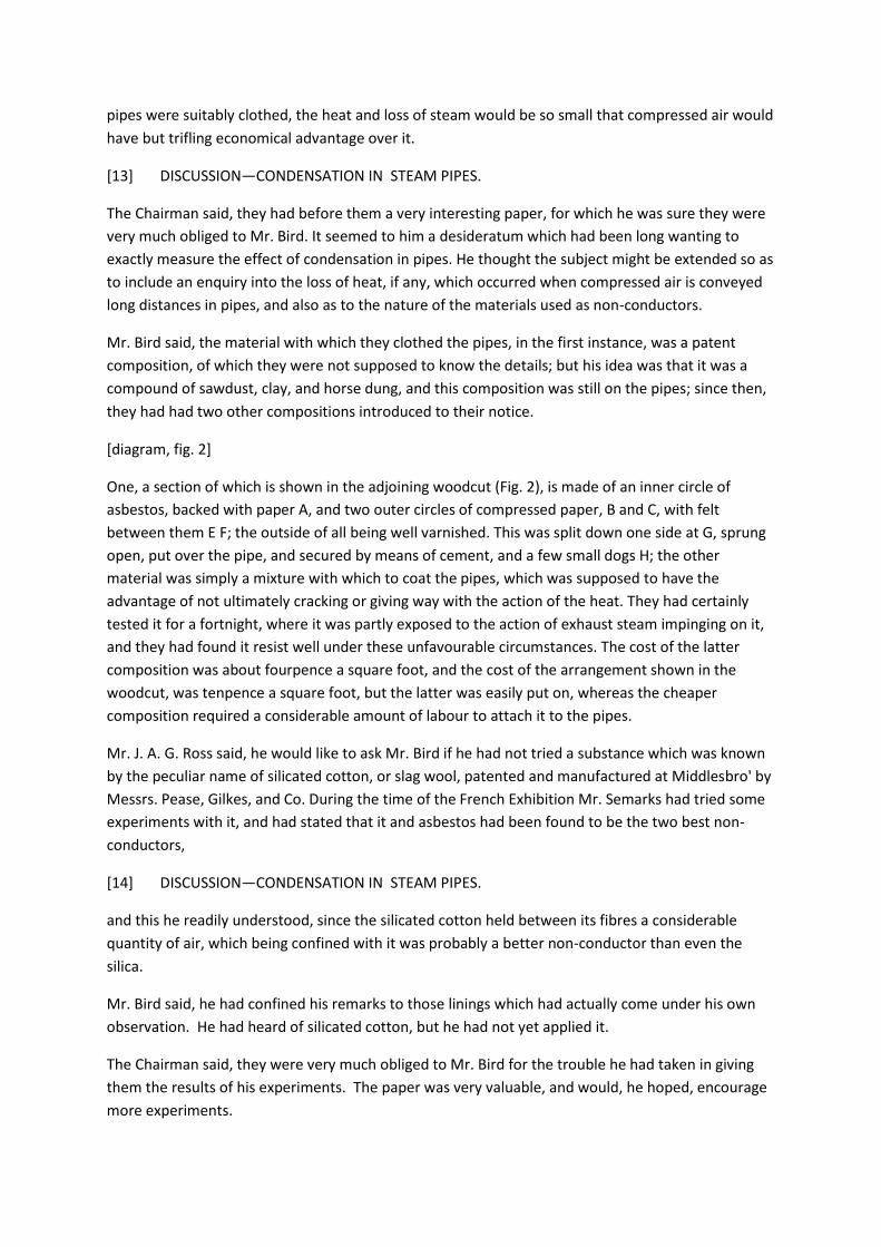
pipes were suitably clothed, the heat and loss of steam would be so small that compressed air would
have but trifling economical advantage over it.
[13] DISCUSSION—CONDENSATION IN STEAM PIPES.
The Chairman said, they had before them a very interesting paper, for which he was sure they were
very much obliged to Mr. Bird. It seemed to him a desideratum which had been long wanting to
exactly measure the effect of condensation in pipes. He thought the subject might be extended so as
to include an enquiry into the loss of heat, if any, which occurred when compressed air is conveyed
long distances in pipes, and also as to the nature of the materials used as non-conductors.
Mr. Bird said, the material with which they clothed the pipes, in the first instance, was a patent
composition, of which they were not supposed to know the details; but his idea was that it was a
compound of sawdust, clay, and horse dung, and this composition was still on the pipes; since then,
they had had two other compositions introduced to their notice.
[diagram, fig. 2]
One, a section of which is shown in the adjoining woodcut (Fig. 2), is made of an inner circle of
asbestos, backed with paper A, and two outer circles of compressed paper, B and C, with felt
between them E F; the outside of all being well varnished. This was split down one side at G, sprung
open, put over the pipe, and secured by means of cement, and a few small dogs H; the other
material was simply a mixture with which to coat the pipes, which was supposed to have the
advantage of not ultimately cracking or giving way with the action of the heat. They had certainly
tested it for a fortnight, where it was partly exposed to the action of exhaust steam impinging on it,
and they had found it resist well under these unfavourable circumstances. The cost of the latter
composition was about fourpence a square foot, and the cost of the arrangement shown in the
woodcut, was tenpence a square foot, but the latter was easily put on, whereas the cheaper
composition required a considerable amount of labour to attach it to the pipes.
Mr. J. A. G. Ross said, he would like to ask Mr. Bird if he had not tried a substance which was known
by the peculiar name of silicated cotton, or slag wool, patented and manufactured at Middlesbro' by
Messrs. Pease, Gilkes, and Co. During the time of the French Exhibition Mr. Semarks had tried some
experiments with it, and had stated that it and asbestos had been found to be the two best non-
conductors,
[14] DISCUSSION—CONDENSATION IN STEAM PIPES.
and this he readily understood, since the silicated cotton held between its fibres a considerable
quantity of air, which being confined with it was probably a better non-conductor than even the
silica.
Mr. Bird said, he had confined his remarks to those linings which had actually come under his own
observation. He had heard of silicated cotton, but he had not yet applied it.
The Chairman said, they were very much obliged to Mr. Bird for the trouble he had taken in giving
them the results of his experiments. The paper was very valuable, and would, he hoped, encourage
more experiments.
A vote of thanks was then awarded to Mr. Bird, and the meeting terminated.
[15] Proceedings
PROCEEDINGS
General Meeting, Saturday, October 4th, 1879, in the Wood Memorial Hall, Newcastle-upon-Tyne.
G.C. Greenwell, Esq., President, in the chair.
The Secretary read the minutes of the last meeting and reported the proceedings of the Council.
The following gentlemen were elected:--
Ordinary Member-
Mr. C. Ernest Bell, Park House, Durham.
Associate Member-
Mr. George Turnbull, Seaham Colliery, Seaham Harbour.
Students-
Mr. Alfred Crawhall Chapman, Silksworth Hall, Sunderland.
Mr. Hugh Bramwell, Tynemouth.
Mr. Wm. C. Murray, South Derwent Colliery, Annfield Plain, via Lintz Green Station.
The following were nominated for election at the next meeting:--
Honorary Member-
Mr. G. A. Lebour, Professor of Geology, College of Physical Science, Newcastle-upon-Tyne.
Student-
Mr. Thomas B. Mackinlay, West Pelton Colliery, Chester-le-Street.
The following paper was read "Notes on Coal Dust Explosions", communicated by Mr. D. P. Morison:-
-
[16 blank page]
[17] NOTES ON COAL DUST EXPLOSIONS.
NOTES ON COAL DUST EXPLOSIONS, ABSTRACTED FROMTHE "ANNALES DES MINES."
A Review of the Paper read before this Institute, by Messrs. A. Freire-Marreco and D. P. Morison,
by M. Louis Dombre.
Communicated by D. P. MORISON.
After reviewing to some extent the important experiments conducted by Mr. Galloway, and
published by him in the Transactions of the Royal Society and other periodicals, the author (M.
Dombre) examining the theory propounded by Mr. Galloway of the danger of a mixture of coal gas
(or fire-damp) and coal dust, proceeds :—
" Messrs. A. Freire-Marreco and D. P. Morison express their opinion that Mr. Galloway's conclusions
are too absolute. According to their views coal dust should be described. There are dusts and dusts,
i.e., that of cannel coal differs from that of anthracite. It may be possible, then, that the dust on
which Mr. Galloway experimented did not possess the qualities requisite to produce explosion
without the presence of an admixture of fire-damp; but the same may or may not apply to other
dusts."
" These considerations induced Messrs. Marreco and Morison to extend the scope of the
experiments of Mr. Galloway," and the results given in the paper already presented to the Institute
are carefully detailed with reproductions of the diagrams and the conclusions to which attention was
invited.
M. Dombre, after criticising the table of flames produced by the various samples of dust submitted,
concludes his paper by the following remarks, which, proceeding from an impartial judge, should
merit attention from the fact of that impartiality, as well as from the interest accruing to his remarks
from several analogous cases cited by him:—
" From the experiments which have given rise to this notice, we think that we may be entitled to
assert—

[18] NOTES ON COAL DUST EXPLOSIONS.
" 1st.—That a gaseous mixture produced by a shot may, in certain cases, set fire to coal dust held in
suspension in the atmosphere of the working places where the shot was fired, and thus produce a
veritable explosion.
" 2nd.—That the nature and composition of the dusts play an important part (un role capital) in the
mode of commencement and in the propagation of such an explosion.
" It is probable that the inflammation of the dust will be (other conditions being equal) more easily
effected and further spread by the fact of the coal which produces the dust possessing a larger
proportion of volatile matter.
" We must now ascertain how far such an explosion will be localised, embracing a district more or
less surrounding its origin, or whether it may under certain circumstances spread through the mine,
and thus become the cause of catastrophes such as those of Pelton, of the pit ' Cing Sols' of Llan, of
Tabin, or of Blantyre.
" This question is one which the results of experiments, however ingeniously conducted, can scarcely
elucidate, and its solution may perhaps for ever be only a theoretical induction.
" It now appears undeniable that in the presence of fire-damp, even in minute proportion, the
explosion, at first local, spreads with rapidity, and may even assume suddenly alarming proportions.
But if no firedamp exists in the workings where the explosion originates, and if none is to be found in
the neighbouring workings, is it to be supposed that the gases evolved by this more or less complete
carbonisation of the dust alone, are sufficient of themselves to sustain combustion, propagating it
and permitting it to feed itself by alimentation from distant districts of the mine?"
In a foot note M. Dombre mentions that, in the explosion of the Javin pit, coke was found in the
timbering nearly 1 1/8 inch, in thickness, and that the analysis of this coked dust proved that 25 per
cent, of volatile matter had been lost between the states of dust and of coke ; or, in other words,
that every kilogramme of dust had given off in weight 70 grammes of inflammable gas, say 7 per
cent., quite enough to account for the most disastrous effects of heat and after-damp which have
yet been experienced.
Blantyre, Swaithe-Main, Pelton, and too many other local sweeping catastrophes point to the dire
effects of dust explosions as exhibited by the coking and charring of bodies, timbers, the sides or
roofs of galleries, at points far distant from any possible reach of gas per se; and here it may be
asked whether any heavy wide spread explosion has been observed and noted in a seam sufficiently
damp to prevent accumulations of dust in the working places or main roads.
[19] NOTES ON COAL DUST EXPLOSIONS.
M. Dombre after some instructive remarks in criticism of the theory that excess of ventilating force
may intensify explosions, and after particularising the support given by M. Chausselle to this idea,
thus potently expresses himself:—

" Although to some slight extent sharing these views, we may observe that in our opinion
improvements in ventilation do not constitute the primordial cause of this tendency of local
explosions to develope into catastrophes, but that the fault lies in the increased area of the workings
themselves and in the large number of men working in one district and in one current of air (this
appears to apply specially to the long wall), or more plainly in the undue concentration of the
working places."
He then adds that increased ventilation has had to follow the necessity created by this increase of
face and workers, and continues:—" Speaking of what he terms the ' paradox' of M. Chausselle, Mr.
Galloway recommends the use of water for laying the dust in workings where powder is used: ' In
future,' he says, ' in addition to the old cry of air, more air, we must add a new one easily supplied,
more water.' Mr. Galloway perhaps overrates the possibility of applying in practice the remedy he
proposes. If the employment of water is practically possible in English mines, the same does not hold
good on the Continent, where the seams are lying at heavy inclinations and under very different
conditions of stratifications.
" Is it not better to cut at the root of the evil, by requiring from the mechanic a tool simple and
handy, suppressing and superseding gunpowder or other igniting mediums in dry and dusty
workings?"
The subject of coal dust and its influence in colliery explosions having now been taken in hand by an
influential and practical committee appointed by the Chesterfield and Derbyshire Institute of
Engineers, well provided with the sinews of war, some further light may be thrown on the almost
unknown influences of dust, heat, and draught in colliery disasters.
The following circular has been issued by the Council of the Chesterfield and Derbyshire Institute of
Mining Engineers :—
The question as to the effects of coal dust aggravating, and even being in some cases the cause of,
colliery explosions, has lately formed the material of a communication to this Institute, and the
investigation of the subject has subsequently been continued and the results embodied in a paper
read before the North of England Institute of Mining Engineers.
In view of the importance of the subject in relation to the safety of life and property, it has been
arranged to institute a series of experiments on the coal dust of this and other districts, in order to
make a comparison with previous tests, and if possible to elicit still further information upon so
important a subject.
[20] DISCUSSION—NOTES ON COAL DUST EXPLOSIONS.
In order to carry out such experiments, there will have to he a certain outlay upon the necessary
apparatus and instruments, and it is estimated that a sum of £50 will he required for properly
carrying out the work.
The Council of the Institute have voted the sum of £10, and the suh-committee have thought it
desirable to lay the question hefore the members of the Institute and others, with a view of getting
their co-operation.
The President said, he was sure the members were very much obliged to Mr. Morison for having
brought before them observations on this important subject which had been made by a gentleman
so competent as Mons. Dombre. They would also arrive at a unanimous conclusion that the question
is still one that requires careful consideration from all those who have opportunities of investigating
it. The members had had placed before them the different conditions which existed in dry and wet
mines. Most of them had the opportunity of making such comparisons, but he was glad to say that
the engineers in this district had most fortunately for some years past been relieved from the
necessity of much personal investigation into such matters. However, it was impossible to foresee
what might happen, and the better prepared all were to meet every contingency that might arise
the less chance of accident would exist, and therefore it would be well if they considered carefully
those points which had been touched upon in the extract which had been read by Mr. Morison, and
he was sure he could not leave it in the hands of better or more able gentlemen than those he saw
before him to further inquire into the matter.
Professor Lebour desired to call the attention of the members to a paper by Professor Peek—an
American scientific man. The paper, which was published in the current number of the " Monthly
Journal of Science," gave details of certain experiments which Professor Peek had made with flour
dust. In most cases these experiments show the very explosive nature of this dust, and they
undoubtedly bore on the subject in hand.
It was then understood that Mr. Morison would kindly make an abstract of the paper referred to by
Mr. Lebour, but afterwards Mr. Morison explained that at present it might be advisable to wait for
the experiments which the Chesterfield and Derbyshire Institute were organizing. They intended to
investigate the question in a much more detailed manner than Professor Marreco and himself had
done, and they were constructing a test-box which he hoped might give explosions without personal
danger to the experimenters, but which would be sufficiently large to represent what might occur
down a drift, everything being in
[21] DISCUSSION—NOTES ON COAL DUST EXPLOSIONS.
proper proportion. They wished to experiment, not only on different dusts as did the North of
England Institute, but to gauge exactly the proportions of dust per cubic foot of air, to follow out Mr.
Galloway's experiments, and to test every proportion, however minute, of fire-damp or coal gas
(both at their disposal); they intended also to vary the temperature of the air in every experiment,
by means of pipes heated by steam, and to imitate the disturbing influences of horses, men, and falls
of coal, by means of agitators placed in the box. They further contemplated testing the force of the
explosion, apart from the damage caused by the flame, this having been found to be very disastrous
in many collieries, and to ascertain how far the ignition of coal dust will blow doors open, by placing
imitation regulators proportionate to the size of the box; and he thought that after these
experiments were completed they might reproduce their own as well as those of the Chesterfield
Institute, and perhaps even subsequent experiments.
Mr. E. F. Boyd asked, if there was any understanding between the Chesterfield Institute and their
own as to the communication of papers?
Mr. Morison said, there was none whatever except that he was a member, and on the Coal Dust
Committee of both.

Mr. Boyd asked, if there was any understanding by which the Chesterfield Institute would favour the
North of England Institute with results of their experiments?
Mr. Morison said he was sure they would, because so far the two Institutes had assisted each other
in every way, and that the two Institutes had really worked to some extent together. He further
stated, that as Professor Marreco and himself were both on the committee appointed by the
Chesterfield Institute, if it was the pleasure of the meeting he could communicate with the Secretary
of the Chesterfield Institute on the subject.
Mr. D. P. Morison then read the following paper " On Boiler Accidents and their Prevention:"—
[22 blank page]
[23] BOILER ACCIDENTS AND THEIR PREVENTION.
ON BOILER ACCIDENTS AND THEIR PREVENTION.
By D. P. MORISON.
PART II.
In resuming this important subject, which by a few introductory notes was already prefaced in a
recent contribution by the author, it is intended to amplify to some extent the figures and statistics
derived from home and foreign compilations. It is also the object of the writer to classify, as far as
possible, the uses, construction, and efficiency of the various societies, or other schemes for
preventing or alleviating the disasters which attend the employment of steam generators or boilers,
and, as far as practicable, to trace their causes, and possibly to suggest means for their prevention.
It may therefore be in the first instance interesting to supplement the figures given in the
Introductory Notes (Vol. XXVIII., p. 249, etc.) by the tables (see Appendix), which bring up the
statistics of our home boilers to the end of last year: Table I. being a summary of the causes of
explosion; Table II. a summary of the construction of the boilers; and Table III. a summary of the uses
to which the boilers were put.
The statistics have been still further amplified in Table IV., which may be taken as a general summary
of all the particulars collected from the various returns of companies, as well as of the Board of
Trade Inspectors, and will, by the mode in which the figures are tabulated, exhibit the various
divisions of the previous statistical separation.
Having now given in detail the results obtained from the data of the last ten years observations, it
may be useful to form some general conclusions which will inevitably occur from the study of the
figures so tabulated.
It is estimated that there are 200,000 boilers in the United Kingdom, but, as previously mentioned,
this is mere conjecture, and is probably an under statement. As all the deductions as to the number
of explosions in proportion to the boilers used depends on correct estimate, it would be
[24] BOILER ACCIDENTS AND THEIR PREVENTION.
useful, as a first step towards correct enumeration, if the Government itself would take up the
matter and institute a boiler " census " (if the term be applicable) for boilers, to ascertain the boilers
in use.
They should be classified—
1.—Marine.
2.—Locomotive.
3.—Portable.
4.—Stationary.
The first three classes are nearly all internally fired, but the fourth class might usefully be divided
into those (a) internally, and (b) externally fired, and further divided into the various types most in
use.
These figures could be obtained through the Inspectors of Coal Mines, the Factory Inspectors, and
the Railway and Marine Department of the Board of Trade. They would form good data as to the
work to be done if all boilers have to be inspected by authority.
At the present moment many boilers are under the care of Companies having for their objects the
inspection or insurance of boilers intrusted to them. In some cases additional precautions are solely
intended, while in others compensation for damages is also guaranteed.
The number of boilers under the care of the different Companies, and their mode of inspecting and
assuring, may now be introduced.
The "Steam Users' Association" was the first formed for inspection only, at about 13s. per annum per
boiler. This did not provide the owner with enough security that the work undertaken would be
efficiently done, and a new Company was created to add assurance as a further guarantee, as well as
compensation for the pecuniary risk involved, which afterwards became the " Steam Power
Company." The "National" is upon the same principle, but encourages what it considers improved
fittings by charging less where certain plugs are used.
The "Midland" was formed by iron and coal masters for the protection of their boilers, as the other
companies, with their head-quarters in Manchester, did not appear willing to undertake the
inspection of hard-worked boilers in iron works and coal mines, especially where heated by waste
gases from furnaces. It was intended at first only as an Inspection Association, but Assurance was
added, as generally preferred by boiler owners.
The "Yorkshire," the "Mutual," the "London Mutual," and the "Newcastle," are on the same
principles as the other assurance companies.
The "Engine and Boiler Company" is comparatively new, but includes the engine for inspection and
assurance.
[25] BOILER ACCIDENTS AND THEIR PREVENTION.
Much discussion has arisen on the subject of Assurance as applied to boilers, under the impression
that it was not so legitimate an object as many other risks, such as those by fire or wreck.
The "Steam Users' Association" denounce it as the source of much evil, as it makes Assurance
Companies eager for business and profit, and thus neglect inspection, and in consequence they have
organised a system of guarantee by which damage is paid in case of failure of a boiler up to £300 for
an annual payment of £1 11s. 6d. The guarantee fund was at first made by ten volunteers being
responsible for £1,000 each, but it is gradually being replaced by accumulated overplus. No profits
are divided, but any overplus is spent on scientific experiment.
The Assurance or Insurance Companies provide guarantee funds like any other joint-stock company
by unpaid capital and reserve funds saved from profits, and they assert that it is a more business-like
and fair way than trusting to volunteer aid. Also, that there is no more reason to doubt that such
business will be done well because a profit is made than that railway companies, or any other
trading companies, will not do their business to the best of their ability to maintain their reputation.
There is perhaps little difference between ordinary assurance and the system of guarantee; but the
real point is, whether either of these, or inspection alone, insures the greater care being taken of the
boilers ?
The chief expense of all the Associations and Companies is the inspection, as a rule, four times a year
of each boiler, and therefore anything that tempts to the slighting of that work is to be feared.
The "Steam Power Company" have carefully compared results of inspection and assurance, but the
figures are not open to testing. The result is said to be that the number of casualties and explosions
have been less among assured than inspected boilers. Other companies have asserted the same
thing, but complete statistics are not easily obtained.
The work of the " Midland Company" has been among the heaviest worked boilers of the kingdom,
as in many iron works the power required is so great that they are composed of little else than
boilers; and until lately it was thought necessary that these should be close to the furnaces and mills,
and of course amongst the men. Considering the great frequency and fatality of boiler explosions
among these more complicated boilers, the number of explosions has diminished in as great a
proportion as in the case of the more easily-managed ordinary mill boilers.
The following notes on our British ideas of inspection, inquests, and Government superintendence,
will pave the way to a more complete investi-
[26] BOILER ACCIDENTS AND THEIR PREVENTION.
gation of the entire subject; and the writer finds that the more the depths of foreign reports are
explored the more the subject becomes extended, and the more the interest accrues. It is, however,
the intention of the writer to condense, as far as possible, in the present series of papers, the
enormous mass of statistics placed at his disposal, so that the practical questions of boiler building,
setting and maintenance, may follow rapidly on these preliminary notices.
INSPECTION.

The highest perfection which could be devised for boilers would be (1) undoubted scientific and safe
form, (2) best materials and workmanship, (3) good mountings and well-regulated fittings, (4)
attention by experienced men fully capable of making a thorough and competent inspection of every
part at short intervals, and (5) that those in charge should take such pride and interest in their work
as never to neglect an opportunity of such inspection.
It has been the ambition of most of the associations to lead up to such a model, but in practice there
are many difficulties in the way, and the vast majority of boilers work under very inferior conditions.
In the first place the forms of boilers differ in a great measure from fancy or the convenience of the
work, and safety is only one out of many considerations in making choice. The most suitable material
and modes of manufacture and proportion of seams and rivets are still matters of conflict and of
opinion. The mountings also may be either as much self-acting as possible or subject to constant
control; and each class has its strong advocates, as in the one case the attendant is lulled into
supposed security by the self-acting fittings, and in the other is liable to accident by any slight
neglect on his part.
The exigencies of modern work demand more division of labour than wasting the time of one able to
inspect on ordinary firing; and last, not least, the attendant is apt to be influenced by the desire to
keep the works going and to postpone the day of inspection. Also, the limited experience of an
ordinary boiler attendant does not usually equal that of an inspector appointed for the sole purpose
of inspection, and with wide experience of all classes of boilers and a good study of many instances
of mishaps from which to form a right judgment as to the best means to avert casualties.
The whole matter becomes one of sound judgment, and experience tells for much, especially in
collieries, factories, iron works, and similar outlying places.
[27] BOILER ACCIDENTS AND THEIR PREVENTION.
INQUESTS.
The Coroner's Inquest is such an ancient and useful institution that it is perhaps well to leave its
investigations as to those killed by boiler explosions, without burdening the juries to add any
scientific reasons for the explosion, in which they can only reflect the opinions most strongly put
before them by interested or other technical witnesses.
It would be convenient, however, if the records of explosions could be obtained with more certainty
than by the private efforts of the Companies.
Without some distinct and recognised authority the majority of cases cannot be properly
investigated; and, as a step towards a boiler "census," a record of explosions, with a short account of
the effect and cause of each, either from special reports or compiled from the reports furnished to
the coroner, would be useful if published in such a form as to be fairly intelligible to the working
men in charge. For this purpose perspective sketches are useful in preference to scientific line
drawings or long tedious descriptions.
Such reports and descriptions as are given of railway accidents and of locomotive explosions of the
Railway Department of the Board of Trade would amply suffice, and be of material assistance to

coroners, juries, witnesses, inspectors, and that portion of the public supposed to be interested in
the enquiries.
GOVERNMENT INSPECTION.
It has been well said that sad as the loss of life by boiler explosions may be, the remedy of
Government inspection is not so certain as to warrant the cost of the army of inspectors needed to
do the work thoroughly; and that the best course is by all means to foster the willingness of owners
to undertake the arrangement for inspection for themselves or through Associations or Companies.
There is a misapprehension as to the Government inspection of marine boilers. The Board of Trade
provide for inspection of boilers in passenger vessels and grant a certificate, but it is optional
whether owners have it or not: but they generally do, as it assists them in case of mishap.
It is considered by many that even if the Government are forced to take the matter up it would be
sufficient to say that all boilers must be inspected by some one, leaving the owner to select, and to
be responsible for the selection of the Inspection Company thought most likely to be efficient at a
moderate cost.
Inspection would then be a fair and useful employment either for individuals or companies, and if all
owners were bound to provide for
[28] BOILER ACCIDENTS AND THEIR PREVENTION.
having each boiler seen inside and outside twice a year at least, a great part of the difficulty would
vanish.
The figures already given of boiler accidents and their attendant loss to life and limb may now be
advantageously compared with the statistics of railway accidents, where effects and causes are
understood to be under the control of, and investigated by, the Board of Trade, i.e., Government
inspection. These are illustrated by Tables V. and VI.
We now come to the results obtained by the German, French, and other foreign associations for the
independent inspection of boilers, which are most carefully and minutely detailed in Tables VII. to
XV., in the Appendix. These tables most plainly indicate the growing anxiety on the Continent for
auxiliary inspection, and the care bestowed on the transactions and reports of the various societies
compares favourably even with the best of our own Companies.
The following extracts and abstracts from the reports of a few of the societies furnishing the
tabulated statistics will be read with interest.
FOREIGN INSPECTION ASSOCIATIONS.
I.—FRENCH AND BELGIAN.
ASSOCIATION POUR LA SURVEILLANCE DES CHAUDIERES, BRUSSELS.
(Boiler Inspection Association.)

1,740 boilers were inspected under this Company in the year ending 1st January, 1878. No explosion
has occurred since the formation of the Association. The annual inspection reports for the year 1877
constitute a most instructive volume, of about 350 pages, with drawings, tables, &c.
The members of the Institute will hail with satisfaction the announcement that in the Board of
Management the names occur of two of their own body, M. Guibal and M. Guinotte, one an
honorary and the other an original member.
The report is noticeable by many most suggestive, although, perhaps, rather self-laudatory remarks,
e.g.:—"The aim of this Association is realized, and we have proved by our own example that all
explosions may be prevented by a relatively inexpensive inspection. * * From ordinary probabilities,
if our Association had not existed and our inspection had not been well managed, five boilers, at
least, would have exploded (Saute).
" You (i.e., the members of the Association) are aware that the greater safety which your boilers
enjoy is not due to repairs being more frequent. On the contrary, thanks to the reports and
examinations of our staff, we
[29] BOILER ACCIDENTS AND THEIR PREVENTION.
have managed in most cases to prevent deterioration, and thus to avoid at once repairs and
accidents.
"During 1877 our staff made 1,641 internal inspections, and 4,098 external examinations, entailing
894 visits of inspectors and 632 of sub-inspectors."
The cost of inspection per boiler was 20s. in 1875, 18s. 6d. in 1876, and 17s. in 1877.
ASSOCIATION PARISIENNE DES PROPRIETAIRES D'APPAREILS
A VAPEUR.
(Association of Steam Power Owners, Paris.)
In February, 1877, this Association numbered 53 members, possessing 148 boilers.
In the report of the engineer, the following are samples of the mode in which the principal defects
are signalised :—
47 steam gauges were defective, of which 18 gave erroneous readings due to the absence of a
proper bend in the pipe between the boiler and the gauge.
Floats in which a rod works through stuffed glands are condemned.
Safety valves.—Firemen are recommended to keep the point of the lever perfectly clean, and to test
its working frequently.
The damper chains are recommended to be brought round to the fire-lioles.

The subject of corrosion from leakages is also dealt with at some length, and, finally, a code of
instructions to stokers is recommended to be distributed to each fireman employed at the boilers
under the Association, of which the following short extract will give some idea:—
INSTRUCTIONS
On usual precautionary measures to be observed in the use of Steam Boilers.
GENERAL OBSERVATIONS.
1.—The surroundings of boilers, fireholes, etc., must always be kept clean.
2.—No admittance of strangers to the boiler house, which must be kept locked during off-time. The
fireman never to leave his post until replaced.
3.—Any imperfection observed in the boilers or connections to be immediately reported by the
fireman to the engineer.
[30] BOILER ACCIDENTS AND THEIR PREVENTION.
FIRING.
4.—The fireman, on his arrival, must verify the level of water in the boiler. If this be correct he will
light up, or when the fire has been damped down, open, first the damper, secondly, the ash-doors,
and lastly, the fire-door. He must then clean his fire and gradually fire up.
5.—Once fired up, the stoker must, every 10 or 15 minutes, throw on small quantities of coal so as
equally to cover each portion of the grate. The lumps to be broken into pieces not exceeding the size
of the fist, and, in ordinary grates, the thickness of combustible must not exceed 5 inches of coal or
10 inches of coke. Each time the door is opened for firing the damper must be partly closed. A small
quantity of water to be kept in the ash-pit.
6.—When the grate, examined from below, ceases to appear free, he must cleanse it half at once,
removing the combustible from side to side. In cleaning he must shut down the damper, taking
advantage of a time when pressure may decrease.
7.—The stoker must open the damper sufficiently only to obtain the required pressure. If the safety
valves blow he must lower the damper without opening the fire-doors.
8.—Half-an-hour before closing time the fire must be slackened; and when time is up the fireman
must cover the fire-grate with ashes or damp slack, and then shut in turn, first the damper, secondly
the fire-door, and thirdly the ash-pit door.
II.—GERMAN, &c.
MAERKESCHER BOILER INSPECTION SOCIETY.
The Society had at the end of 1877, 422 boilers. The number of inspections were 1040, of which
622 were external inspection.
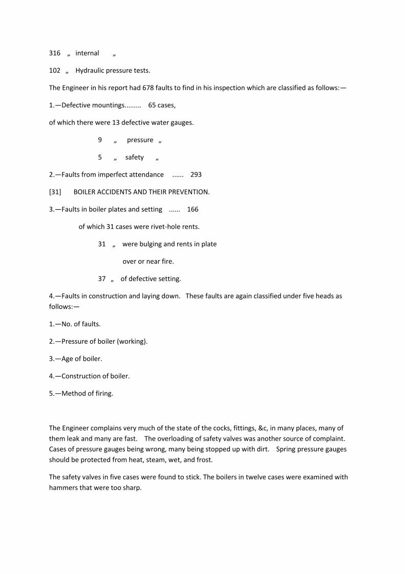
316 „ internal „
102 „ Hydraulic pressure tests.
The Engineer in his report had 678 faults to find in his inspection which are classified as follows:—
1.—Defective mountings......... 65 cases,
of which there were 13 defective water gauges.
9 „ pressure „
5 „ safety „
2.—Faults from imperfect attendance ...... 293
[31] BOILER ACCIDENTS AND THEIR PREVENTION.
3.—Faults in boiler plates and setting ...... 166
of which 31 cases were rivet-hole rents.
31 „ were bulging and rents in plate
over or near fire.
37 „ of defective setting.
4.—Faults in construction and laying down. These faults are again classified under five heads as
follows:—
1.—No. of faults.
2.—Pressure of boiler (working).
3.—Age of boiler.
4.—Construction of boiler.
5.—Method of firing.
The Engineer complains very much of the state of the cocks, fittings, &c, in many places, many of
them leak and many are fast. The overloading of safety valves was another source of complaint.
Cases of pressure gauges being wrong, many being stopped up with dirt. Spring pressure gauges
should be protected from heat, steam, wet, and frost.
The safety valves in five cases were found to stick. The boilers in twelve cases were examined with
hammers that were too sharp.

THE SWISS BOILER OWNERS' ASSOCIATION.
At the end of the year 1877 this Association had 1,182 boilers under its inspection.
The following important official notice is worthy of attention:—
THE GOVERNMENT,
Having had under consideration a proposition from the magistrature and the police authorities,
DECREES:
1.—That the laying down and working of all boilers shall be under the inspection of the district
police, who will, through their engineer, carry out this order.
2.—That in laying down boilers the first consideration shall be solidity, so far as regards material and
construction, for the purpose of insuring its safety and its proper working as well as its connections,
all precautions being taken as understood by the technical world to make its situation safe and
innocuous and its surroundings also secure from explosion and fire, and otherwise to keep it free
from damage or molestation.
3.—That before a boiler starts work notice shall be given to the district police, who, by inspection
and trials, shall see that the above measures of precaution have been carried out.
[32] BOILER ACCIDENTS AND THEIR PREVENTION.
Should the inspection and trials not be satisfactory, the working of the boiler shall be prohibited.
4.—All working boilers shall be liable to periodical inspection at least twice per annum.
5.—These inspections shall be—
1.—External.
2.—Internal and external together.
Each of which shall at least be done once yearly.
The external examinations shall be directed to the exposed portions of the boiler furnace and boiler
mountings, and shall be only effected when the boiler is at work. The engineer at the same time to
see how the stoker peforms his special duty.
The internal and external examination shall consist of detailed internal and external examinations of
all parts of the boiler and flues, especially those parts that have been found defective during the
examination of the boilers while at work.
In the case of internal examination every preparation must be made, so that on the arrival of the
inspector the boiler shall be emptied, cooled, and the flues and other parts of the boiler cleaned and
freed from rust.
The entire inspection shall be mutually arranged between the boiler owners and the inspector.

6.—In the case of boilers under the Swiss Boiler Inspectors Association, any inspection made by the
engineer of the Association will be taken as sufficient for the above purposes.
In the case of boilers which are not under the inspection of the Swiss Association, the owners of it
then shall have the option of having them inspected either by the Swiss Association or by other
engineers. In either case notice must be given to the Board of Justices or to the police by those
undertaking the inspection.
In cases where the inspection is made by engineers not belonging to the Association, their inspection
shall be laid before the Board of Justices or the police who shall decide whether such inspection shall
or shall not be taken as correct.
Should a boiler owner not specify the inspection under which his boiler shall be placed, the police
will then take such inspection into their own hands.
7.—The expense of inspection shall be defrayed by the owner of the boiler.
8.—The results of all inspections shall be communicated to the police and the owners of the boiler.
[33] BOILER ACCIDENTS AND THEIR PREVENTION.
Should these results not be found satisfactory a further inspection shall be made, at the instance
either of the owner or of the police, but at the expense of the owner.
9.—Should any boiler owner not follow the law laid down in this decree, he shall, notwithstanding
any loss or damage which he may thus incur through explosion or any casualty, be liable to a fine of
500 francs, and be further liable to be summoned before the magistrates for not carrying out the
decree of the Government.
10.—The Board of Justices and the police are directed, etc., etc., Zurich.
SILESIAN BOILER INSPECTION SOCIETY.
This Society at the end of the year 1877 had 672 boilers under its inspection.
In the Engineer's report for the year 1877 the attention of the steam users was directed to the
following faults which seem to prevail:—
Safety valves should have water pipes attached to allow the waste water to escape when lifting the
valves during trial, and thus prevent it from filling the interstices between the boiler and the
brickwork.
The sludge cock should be fitted close to the boiler instead of at the end of a pipe.
Safety valves sticking fast. Valves with conical bearing surfaces have a tendency to stick. The bearing
surface should be straight, horizontal, and small.
Test cocks have a tendency to fasten, owing to leakage.
Only one explosion occurred in 1877 amongst the boilers insured by this Society.

NORTH GERMAN BOILER INSPECTION SOCIETY.
The Society had in 1877 under its inspection 662 boilers. No explosion took place amongst the
boilers under their inspection during the year 1877. Among the boilers under their inspection, there
were 212 cases in which faults were detected, and these were classed under five heads, viz.:—
Cases.
1.—Defects in erection ... ... ... ... 7
2.—Defective materials of boilers—
(a.)—Not safe—present ... ... ... 16
(b.)—Not safe—future ... ... ... 111*
3.—Defective mountings ... ... ... ... 5
4.—Imperfect working of the boilers ... ... 56
5.—Otlier causes ... ... ... ... 17
------
212
* i.e., cases where defects (unless remedied) may increase.
[34] BOILER ACCIDENTS AND THEIR PREVENTION.
Attached to their Annual Report is the receipt for a grease to be used on test cocks to make them
water and steam tight, the composition of which is as follows:—Half a pound of tallow, a quarter of
a pound of wax, and a quarter of a pound of gutta-percha, which when melted together forms the
grease.
THE BAVARIAN BOILER INSPECTION SOCIETY.
This Society had at the end of the year 1877, 1,301 boilers under its inspection.
The Engineer in his report classifies the defects occurring under his inspection as follows:—
Cases.
1.—Defective boiler mountings and connections ... 293
2.—Defective boiler attendance ... ... ... 327
3.—Dangerous condition of boilers and brickwork

setting ... ... ... ... ... 396
4. —Faults construction of boilers and boiler seat ... 355
To prevent the corrosion in boilers from acids which exist in oils, &c, the engineer suggests a test of
a chemical nature to be applied to oils which will prove the existence of acids if present.
No explosion has occurred within the last five years among the boilers under the inspection of the
above Society.
The objects aimed at by the Society are:—(1.) Increased safety in working boilers through prevention
of explosions as far as possible; (2.) Economy in the use and raising of steam; (3.) Increase of
duration of boilers with minimum cost of repairs; (4.) Advice on the construction and laying down of
boilers; (5.) Guaranteed official competence of the Society's engineer; (6.) All trials and inspections
carried out in accord-with Government regulations.
It is further stated in the report of the Society that hydraulic tests serve only to support internal
examinations, which are the only means of ascertaining the conditions and the safety of boilers.
Internal examination consists in inspecting and examining the boiler and its flues by entering the
boiler and traversing the flues.
All parts of the boiler should be properly examined, because it is possible that each per se may be
defective.
THE SAXONY BOILER INSPECTION SOCIETY.
This Society in 1877 had 640 boilers under its inspection. It is in connection with the Boiler
Inspection Society's Union, to which 26 Societies belong, inspecting a total of 17,432 boilers.
[35] BOILER ACCIDENTS AND THEIR PREVENTION.
During the year 1877 the engineer made 1,790 inspections of the 640 boilers in his charge, of which
1,290 were external examinations, 362 internal examinations, and 138 pressure tests; and, as a
result of these inspections, 573 defects were detected.
These defects are classified as follows:—
1.—External examinations.
(a.)—Mountings.
(b.)—Working of the boilers.
(c.)—Brickwork or setting.
2.—Exposed by internal examination.

(a.)—Construction.
(b.)—Plates and seams.
(c.)—Workmanship.
(d.)—Imperfect cleaning.
3.—Faults exposed by pressure tests.
The most prevalent faults exist in pressure gauges and insufficiency of water gauges in each boiler,
two being required, their errors amounting to 130. The engineer in his report states that
unfortunately the safety valves are tampered with in many places and too little care is taken to keep
the water level in the boilers at its proper height.
No explosion has occurred among the boilers of the Society.
The considerations and conclusions to be drawn from these statistics and reports are intended to be
reviewed by the writer in his next contribution, before proceeding to the questions of boiler seatings
and boiler materials.
[36] BOILER ACCIDENTS AND THEIR PREVENTION.
APPENDIX.
TABLE I.
Boiler Explosions, 1869 to 1878.—Summary of the Causes of Explosion.
No. of No. of No. of
Boilers Persons Persons
Exploded. Killed. Injured.
(A).—Faults in construction or repairs ... ... ... 183 205 370
(B).—Faults which could be detected by periodical examination .................. 178 206
401
(C).—Faults which could be prevented by careful attendants .................. 245 288 420
Extraneous or uncertain causes ... 24 7 28
------ ----- -----
Total ............... 630 706 1219
TABLE II.
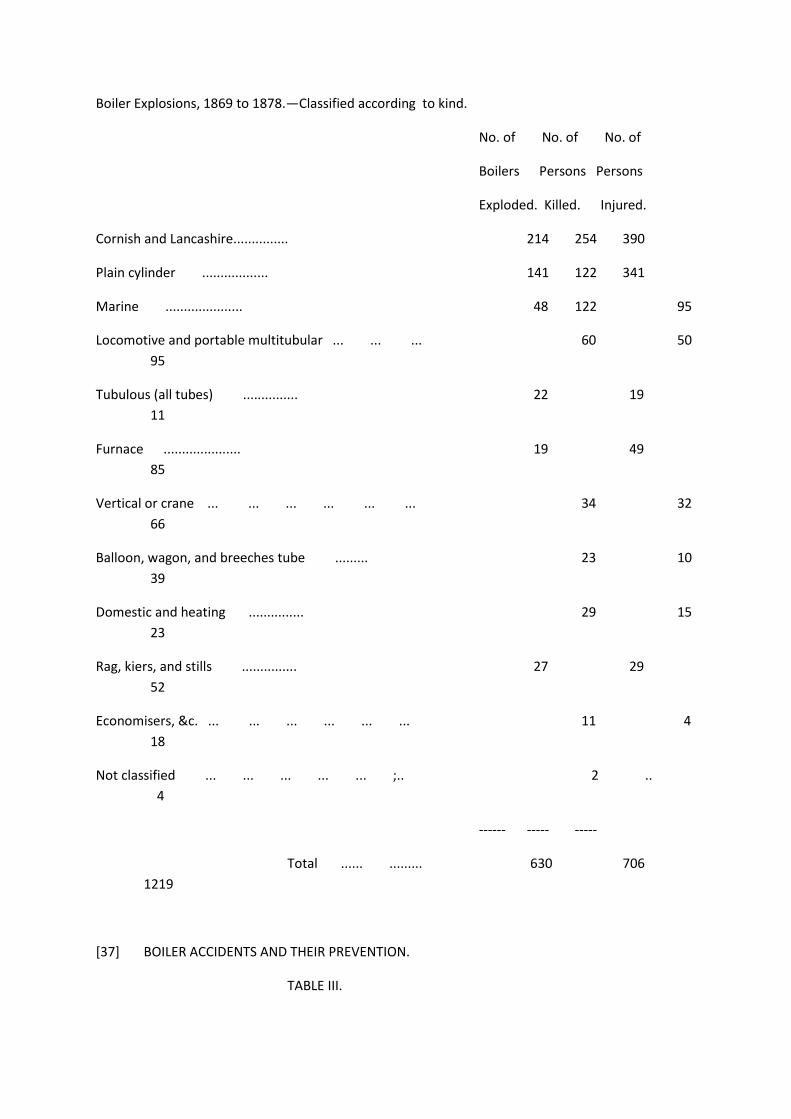
Boiler Explosions, 1869 to 1878.—Classified according to kind.
No. of No. of No. of
Boilers Persons Persons
Exploded. Killed. Injured.
Cornish and Lancashire............... 214 254 390
Plain cylinder .................. 141 122 341
Marine ..................... 48 122 95
Locomotive and portable multitubular ... ... ... 60 50
95
Tubulous (all tubes) ............... 22 19
11
Furnace ..................... 19 49
85
Vertical or crane ... ... ... ... ... ... 34 32
66
Balloon, wagon, and breeches tube ......... 23 10
39
Domestic and heating ............... 29 15
23
Rag, kiers, and stills ............... 27 29
52
Economisers, &c. ... ... ... ... ... ... 11 4
18
Not classified ... ... ... ... ... ;.. 2 ..
4
------ ----- -----
Total ...... ......... 630 706
1219
[37] BOILER ACCIDENTS AND THEIR PREVENTION.
TABLE III.

The Boilers that Exploded in the Years 1869-78 were used for the following purposes.
No. of No. of No. of
Boilers Persons Persons
Exploded. Killed. Injured.
Collieries and mines ... ... ... ... ... 131
92 204
Ironworks..................... 122 175
355
Mills of various kinds ............... 70 75
134
Marine ..................... 55 127 102
Railway ............... ...... 35 18
45
Agricultural .................. 22 20 26
Chemical ..................... 39 33
48
Sawing, turning, building, and glass ... ... ... 29 38
83
Brickworks..................... 19 26
60
Paper mills..................... 23 32
43
Flour mills..................... 22 21
18
Brewing and malt mills ... ... ... ... ... 7 9 14
Cranes ... ... ... ... ... ... ... 5 5 3
Hauling and pressing ... ... ... ... ... 5 16
40
Pumping ... ... ... ... ... ... ... 5
3 2
Domestic or heating ... ... ... ... ... 31
15 26

Unknown..................... 10 1
16
------ ----- -----
Total ............... 630 706 1219
TABLE IV.
DETAILS OF EXPLOSIONS.
The Exploded Boilers in the Ten Years, 1869-1878 (inclusive) were of the following description.
The Causes are arranged as in the Summary under heads A, B, and C.
No. of No. of
No. of
CORNISH AND LANCASHIRE. Boilers Persons Persons
Exploded. Killed. Injured.
(A).—Bad construction, weak tubes or chambers, want
of stays, bad manlids, bad repair ... ... 64 81 120
(B).—External and internal corrosion ... ... ... 73 90 161
(C).—Shortness of water, undue pressure, deposit, fires
forced too quickly, manlids opened too soon,
carelessness with valves or pipes ... ... 77 83 109
---- ---- -----
214 254 390
Plain Cylinders. — — ------
(A).—Bad construction or material, seam rip, bad repair,
or bad manholes ............ 57 49 128
(B).—External or internal corrosion ... ... ... 41 46 132
(C).—Shortness of water, deposit, undue pressure, carelessness with valves, or
fall of steam pipes... 41 26 81

Not ascertained ... ... ... 2 1 ---
---- ---- ----
141 122 341
[38] BOILER ACCIDENTS AND THEIR PREVENTION.
[tables]
[39] BOILER ACCIDENTS AND THEIR PREVENTION.
[tables]
[40] BOILER ACCIDENTS AND THEIR PREVENTION
[tables]
[41] BOILER ACCIDENTS AND THEIR PREVENTION.
[tables]
[42] BOILER ACCIDENTS AND THEIR PREVENTION.
[tables]
[43] BOILER ACCIDENTS AND THEIR PREVENTION.
[tables]
[44] BOILER ACCIDENTS AND THEIR PREVENTION.
[tables]
[45] BOILER ACCIDENTS AND THEIR PREVENTION.
[tables]
[46] BOILER ACCIDENTS AND THEIR PREVENTION.
[tables]
[47] BOILER ACCIDENTS AND THEIR PREVENTION.
[tables]
[48] DISCUSSION—BOILER ACCIDENTS.
Mr. D. P. Morison stated, that in a third paper he intended to take up the subject of the setting and
arrangement of boilers and their flues, and he hoped to get the assistance, as far as possible, of the
members of the Institute. In a further paper he proposed to deal with the materials and construction
of the boilers themselves. He might add, that Mr. Marten had been kind enough to lend a most
valuable set of models for the proper elucidation of the paper; and one of their inspectors, Mr.
Winship, was present and would be glad to explain them to any member who would like to see
them.
The President asked, whether it would be better to have the discussion now or wait till the whole of
the papers were forthcoming before having a general discussion on the whole? He supposed that
before Mr. Morison had finished he would be able to tell the members which was the safest kind of
boiler, and also to tell them under what conditions the greatest safety could arise from the working
of that boiler.
Mr. Morison said, that as they had the advantage of Mr. Marten's presence, there were one or two
points in connection with boilers which his practical experience would enable him to explain, and
which perhaps it would be an advantage to the members present to hear.
The President said, he was sure the meeting would be very glad to hear anything which Mr. Marten
had to say upon the subject.
Mr. E. F. Boyd proposed a vote of thanks to Mr. Morison for the very interesting details which he had
given the members. He (Mr. B.) must express the hope that every gentleman who was concerned in
his own department of trade would render every assistance to Mr. Morison in trying to make as
complete as possible the remaining papers which he proposed bringing before them.
The motion, seconded by Mr. Newall, was carried by acclamation.
Mr. Marten said, of course it would have been more convenient if he had been able to hear such
questions as might occur to the members in the discussion, and so if possible to have answered
them. He thought the object of the last paper was to ascertain whether the inspection of boilers was
really necessary, or whether boilers may, if they are good, be left to themselves without inspection.
His own conviction was extremely strong on the subject that, no matter how good a boiler might be,
inspection should be added, for no boiler can be relied upon that has not been surveyed in all its
details at least once a year, and he thought that the Institution would arrive at the same conclusion.
All boilers, even of the very highest class, and made by the most careful firms, have still been liable
to explosion. Evils had arisen
[49] DISCUSSION—BOILER ACCIDENTS.
which had been thought never would arise, but which in practice do arise, and therefore his opinion
was very strong—that somebody ought to see and if possible feel every part of a working boiler at
least once a year. The reason why he acceded to the request to bring before them these models of
exploded boilers was, that he thought there still remained many of the old mysterious ideas of
explosions; for instance, that they arise from electricity, or from the decomposition of steam, or the
spherical condition of water; and he thought, therefore, that more careful investigations by those
gathering their experience from many explosions would be extremely useful. He had taken very
great pains to obtain the record of every explosion which had taken place since 1800. He found no
other method of investigation so good as making a model of all the parts and placing them, first in
the position in which they were before the explosion, and then in the position in which they were
found after the explosion ; this done, the place where the boiler first gave way became almost
invariably apparent, and the investigation was narrowed into what made that particular place give
way, and it was very seldom indeed that any mistake could be made; but it was too often the case
that a cursory view of an explosion produced the idea that there must have been some greater force
in the boiler than the mere compression of steam; whereas, if a calculation was carefully made, it
would be found that there was no working boiler but had force enough within it to blow it all to
pieces if only a first rent is made. Perhaps he need say very little about any particular system of
inspection; that will best be spoken of at a future meeting. If the members should come to the
conclusion that inspection of some kind was desirable, his own view was that it was best done, not
by Government, but by the owners themselves selecting the person who should do it; because then
those who did it would have to do it well, or they would not be employed, and the responsibility to
the owners would still remain. He thought that this was much more desirable than that the
inspection should be entrusted to an irresponsible set of Government Inspectors of which it would
take something like 200 to attend properly to the business.
There was a class of boilers generating steam at from 500 to 600 pounds to the inch; that was not
very generally known; and he, thinking it would be interesting to the members present to hear some
account of the system, had brought with him one of the tubes of a Perkins' boiler, and he asked to
be allowed to use it as an illustration of what he considered to be the theoretically perfect way of
using a boiler. Some of the gentlemen present were very likely familiar with Perkins' field ovens for
the use of an army when in the field, a section of which is shown in Plate II., Fig. 1. They consisted
[50] DISCUSSION—BOILER ACCIDENTS.
of a number of pipes about half an inch internal diameter, with a small quantity of water in the end
within the fire. As the heat was taken from the steam in the top part of the pipes by the oven, the
condensed steam fell to the bottom in the shape of water and was re-circulated as before without
any loss of the original supply. In manufacturing these tubes one end is first welded up and enough
water put in to fill one-tenth of the length; the other end is then put into a smith's fire and welded
up solid. During this process about ten inches of the tube becomes red-hot. As soon as the
blacksmith has finished welding it up he turns it over, and the water runs into the red-hot part. The
first effect of this is that the red-hot part becomes rapidly chilled, but the hitherto cool part almost
instantly becomes very hot, showing that the water is quickly converted into steam, and he believed
the pressure in the tube thus manipulated was fifteen atmospheres. This illustrated the fallacy of the
often repeated statement that if cold water is poured on to a red-hot boiler it must necessarily
explode, for every day hundreds of these are turned over in this way without accident. He thought
that the tube receiving the water so suddenly into the hot end might be compared to a boiler, the
flue of which is red-hot by misadventure, and that the circumstance of the tube not exploding
combated very much the theory that boilers must explode simply by throwing cold water into their
red-hot flues. This Perkins' boiler was also mentioned as an illustration of what was ultimately hoped
for in boiler engineering. He thought this oven tube was very useful as showing how steam might be
generated over and over again from the same water without any loss, and thus all the difficulties
attendant on the deposit caused by the introduction of so much fresh water into the boilers at
present in use would be avoided. In Plate II., Fig. 2, a slight sketch was given of the Perkins' engine,
which was driven by a number of tubes made in the same way as those for the oven, where the
steam at a pressure of 400 or 500 lbs. to the inch was utilized, condensed, and returned into the
lower end of the tube with scarcely any loss. He had seen one of Mr. Perkins' engines which had
worked eight years, during which time the boiler had received but very little additional water. A
great many difficulties could be got over if the ordinary working boilers could be made to assimilate
to something like this conditon. He did not think it could be done at once, but it was a very good
example to keep before them of what he thought was a perfect use of steam. With regard to
inspection, he thought that no attempt should be made to persuade the public to adopt any
particular kind of boiler, but that the inspectors should endeavour to cause those boilers, which the
proprietors thought most
[51] DISCUSSION—BOILER ACCIDENTS.
suitable for their particular purposes, to be so constructed and maintained as to be as safe and
durable as possible, and he had always kept this before himself and the officials whom he directed.
Mr. K. S. Newall said, Mr. Marten had referred to Perkins' engine but had not referred to a steamer
on the Tyne which is fitted up with such a boiler and engine, which works at a pressure of 450 lbs. to
the inch, and in which the water is so condensed and used over again as to require a very small
additional supply to the quantity originally introduced. There was a very great saving of fuel by the
process, as Mr. Perkins had stated that the consumption was less than a pound and a half per horse
power per hour.
The next paper for reading was one by Mr. Edwin Gilpin, A.M., F.G.S., Inspector of Mines, entitled
"Notes on Nova Scotia Pit Waters."
The President said, the gentleman who had presented this paper resided at a distance, and, as it
seemed to be a subject which required study and did not well admit of being read in public, perhaps
it would be well to have it printed and laid before the members and then discussed.
The paper was then taken as read, on the understanding that it be printed in the Transactions, and
the meeting terminated.
[000 blank page]
[000 Plate II To illustrate Mr. E.B. Marten's remarks on Perkins' Field Ovens
[52 blank page]
[53] NOVA SCOTIA PIT WATERS.
NOTES ON NOVA SCOTIA PIT WATERS.
By EDWIN GILPIN, A.M., F.G.S., Inspector of Mines.
The composition, sources, and effects of the hidden springs of the earth are as yet so little known,
and the field for investigation is so wide and varied, that the time has not yet arrived for reliable
deductions; but it may be expected that at some future day the composition of mineral springs and
the waters cut by boreholes, &c, may be brought into the service of man, and furnish valuable
information about the proximity of mineral deposits and strata.

So far as the writer is aware, but four analyses have as yet been made of Nova Scotia pit waters. Two
of these are of waters from the Pictou coal district, and two from the Cape Breton district; they,
however, represent fairly the characteristics of the waters of the two districts.
At the Blockhouse Colliery, Cape Breton, the pit water has a corrosive effect on the ironwork
exposed to its action. The following analysis was made in the laboratory of the Canadian Geological
Survey, 1872-73 :—
Suspended Matter.
Sulphate of iron ... ... ... ... ... ... ... .1510
In Solution.
Iron (aspersalt) ... ... ... ... ... .. ... .2426
Iron (asprotosalt) ... ... ... ... ... .1168
Manganese ..................... .0078
Aluminium ... ... ... ... ... ... ... .0420
Calcium........................ .1498
Magnesium ... ... ... ... ... ... ... .0618
Potassium........................ .0134
Sodium ........................ .1884
Silica ........................ .0116
Sulphuric acid ..................... 1.4808
Chloric ........................ .4100
Phosphoric acid..................... traces
Organic matter ... ... ... ... ... ... ... 2844
---------
Total constituents in 1,000 parts ...... 3.0094
Water, yellowish-brown colour, acid reaction, and styptic taste.
[54] NOVA SCOTIA PIT WATERS.
The Blockhouse Seam immediately overlies the Gowrie Seam, worked by Messrs. Archibald. In Vol.
XXVI, p. 56, of the Transactions, there is an interesting account of the difficulties that gentleman met
with in overcoming the destructive effects of the water found in their pit. There is no analysis of the

water from the Gowrie Mine, but, from its appearance and action, there is no doubt but that the
analysis given above will also indicate its composition.
At several other collieries in the Cape Breton district similar corrosive powers appear in the pit
waters, and have caused much annoyance to those engaged in conducting mining operations.
Direct-acting force pumps are very generally employed, and frequently require replacement of the
iron working parts by compositions similar to that used at the Gowrie, such as brass, babbit metal,
and lignum vitae. No doubt the heat induced by the steam would tend to increase this corrosive
tendency, but the portability of these pumps, and the general adoption of slope winnings, cause
their retention. When, through ignorance or a false economy, these waters are introduced into the
colliery boilers, an immediate and energetic corrosion takes place. The boilers used in Cape Breton,
with a few exceptions, are cylindrical egg-ended, externally fired. The action of the water is shown
by cutting the rivet heads—severe pitting, a planing away of some of the plates over a space of
several square inches, and generally a deposit of hard scale on the lower back end plates.
A scum-collector, invented by Mr. W. M. Rumble, Mechanical Superintendent, Cape Breton Coal Co.,
has been found to materially prevent the destructive effect of these waters at the Emery Colliery.
The description of it is from the Report of the Inspector of Mines for 1877 :—"It may be described
generally to consist of a two-inch pipe leading from near the back end of the boiler up to an 18-
gallon receiver, placed above the boiler and nearly over the fire bridge ; from the receiver pass two
pipes, one to the open and the other directly downwards through the shell to low-water line, where
it branches into two transversely-placed bell mouths, each having a diameter equal to the difference
between high and low-water in the boiler. The circuit being made by the necessary valves, a current
of water flows through the system in a contrary direction to the order of the above description. Then
as the strongest ebullition occurs where the bell mouths are placed, the scum in the water is thrown
to the surface and passes up into the receiver where it settles, and from Avhich it is periodically
blown out through the second pipe."
The pit water from the Gardener Colliery has developed all the above injurious qualities in a marked
manner. The following analysis of this
[55] NOVA SCOTIA PIT WATERS.
water, made by the writer some time ago, shows a composition similar to that of the Blockhouse
water :—
Iron sulphate ... ... ... ... ... ... ... 2.750
Potassium sulphate ... ... ... ... ... ... .185
Calcium carbonate ... ... ... ... ... ... .736
Magnesium carbonate ... ... ... ... ... ... .025
Sodium chloride ... ... ... ... ... ... ... .960
Alumina ... ... ... ... ... ... ... ... trace

Silica ........................ .225
-------
Total in 1,000 parts ............ 4.881
Water, clear with bluish shade; after standing, deposited reddish sediment; acid reaction, and highly
styptic taste.
This water also exerted a corrosive action on the force pumps and the wrought-iron rising columns.
The action on the latter was mitigated by a coating of oxide of iron deposited by the water. As this
coating was nearly one-half inch thick in a 5-inch pipe, the partial protection thus afforded was
attended with a lessened area through the pipe.
Passing to the Pictou coal-field there is a class of waters of a totally different character and of a
comparatively innocuous nature. The following analysis of the pit water of the Vale Colliery, made by
the writer a short while ago, is as follows:—
Iron and alumina... ... ... ... ... ... ... traces
Magnesium carbonate ... ... ... ... ... ... „
Calcium carbonate ... ... ... ... ... ... „
Sodium chloride ... ... ... ... ... ... ... 1.452
* Sodium carbonate ... ... ... ... ... ... 7.509
Magnesium sulphate ... ... ... ... ... ... .100
Calcium sulphate... ... ... ... ... ... ... .514
Potassium... ... ... ... ... ... ... ... traces
Silicious matter ... ... ... ... ... ... ... .190
Organic matter ... ... ... ... ... ... ... trace
---------
Total in 1,000 parts ............ 9.765
Water, clear and colourless; at first it gave no reaction, but after boiling became alkaline.
* The percentage of sodium carbonate appeared so large that the determination was repeated, and
the former result confirmed ; the percentage given is an average of both determinations.

This water has been used a little as a boiler feed, and has not shown any injurious effects.
The second analysis of Pictou pit water now given is one of the water from the Nova Scotia Colliery,
situated at the western extremity of the
[56] NOVA SCOTIA PIT WATERS.
district, made by Dr. H. How, King's College, Windsor, N.S., giving the following results:—
Silica ........................ .460
Calcium carbonate ... ... ... ... ... ... 10.590
Magnesium carbonate ... ... ... ... ... ... 3.570
Iron carbonate ... ... ... ... ... ... ... traces
Sodium chloride ... ... ... ... ... ... ... 1.170
Potassium sulphate ... ... ... ... ... ... 1.580
Sodium sulphate ... ... ... ... ... ... .... 2.500
Sodium carbonate ... ... ... ... ... ... 3.350
Phosphoric acid ... ... ... ... ... ... ... none
Organic matter ... ... ... ... ... ... ... traces
-- ------
23.220
Water, bright and clear; no odour, slightly acid; after boiling gave alkaline reactions. Calculated
in grains to the imperial gallon.
These waters have been used to some extent mixed with surface water, with no markedly injurious
effects.
On comparing the Pictou and Cape Breton pit waters it will be at once seen that the latter contain
very large quantities of iron sulphates, and the former large percentages of alkaline carbonates.
These waters all differ from any of the Canadian pre-carboniferous waters, which are fully described
by Dr. Sterry Hunt in Sir William Logan's " Geology of Canada," 1863. The Canadian waters, arising
from comparatively undisturbed measures, present constituents derived from limestones,
dolomites, argillaceous sediments, and feldspathic rocks, which admit of their division into six
classes. The number of Nova Scotia pit waters analysed is too small to admit of any deductions
which can be considered reliable. But there are a few points, which may to some extent account for
these widely-divergent results. In considering the composition of these pit waters found in workings
of moderate depths, it may be assumed that they are accumulated partly from surface water
filtering downwards, and partly from water rising from lower measures by hydrostatic pressure
through the strata, or by means of faults.
The strata containing the Cape Breton coals are largely composed of sandstones, many of which hold
numerous disseminated crystals of iron sulphurets, while the shales which predominate in Pictou
County are comparatively free from this ingredient. This and the larger percentage of iron pyrites
and organic compounds of sulphur in the Cape Breton coals may account for the large amounts of
iron sulphates the former contain. The preponderance of sodium chloride in the Pictou pit water
may be explained by the fact that on the southern edge of the district,
[57] NOVA SCOTIA PIT WATERS.
whence the waters analysed were taken, the Lower Carboniferous limestones and gypsums come
against the coal-measures with very little intervening millstone grit, and the heavy faults bounding
the district would allow the admission of their waters to the workings. In Cape Breton, on the other
hand, the coal-measures are comparatively undisturbed, and a great thickness of millstone grit must
intervene between them and the marine (Lower Carboniferous) limestones. In both districts
limestone is almost entirely wanting in the coal-measures.
The following analysis of a Cape Breton Lower Carboniferous water, from the Little Narrows of the
Bras d'Or Lake, made by the analyst to the Geological Survey, 1873, is given for comparison :—
Sodium chloride..................... 50.6881
Potassium chloride ... ... ... ... ... .1942
Magnesium chloride ... ... ... ... .1592
Calcium sulphate ... ... ... ... 5.6810
Alumina... ... ... ... ... ... traces
Silica ... ... ... ... ... ... „
Ferric oxide suspended, originally present, )
probably as ferrous carbonate .. ... ) .0054
------------
Total in 1,000 parts ............ 56.7279
This fairly represents the composition of the Lower Carboniferous waters, although in cases where
they rise from highly gypseous portions of these measures, the calcium sulphate sometimes
predominates.
This derivation of the sodium chloride from the marine limestones in the case of the Pictou waters
may be supported by the fact that at the Vale Colliery, where the Lower Carboniferous measures are
a comparatively short distance away, the cleats of the coal are frequently coated with films of

selenite up to one-quarter of an inch in thickness ; and it will also be observed that the water from
this mine contains a considerable amount of calcium sulphate. The unusually large percentage of
sodium carbonate present in the waters from the Vale Colliery does not at first seem easily
accounted for, unless it owes its origin to the argillaceous shales which were formed from the
granites and silurian slates of the hills lying to the south of the district.
The comparatively small amounts of magnesium salts present in all the Nova Scotia pit waters may
perhaps be owing to the fact that this mineral is not abundant in the province—an average of
twenty analyses of Lower Carboniferous limestones giving but .75 per cent. of magnesium
carbonate.
[58 blank page]
[59] PROCEEDINGS.
PROCEEDINGS.
GENERAL MEETING, SATURDAY, NOVEMBER 1st, 1879, IN THE WOOD MEMORIAL HALL,
NEWCASTLE-UPON-TYNE.
G. C. GREENWELL, Esq., President, in the Chair.
The Secretary read the minutes of the last General Meeting and the minutes of the Council
Meetings.
The following gentlemen were then elected :—
Honorary Member—
Mr. G. A. Lebour, Professor of Geology, College of Physical Science, Newcastle-upon-Tyne.
Student— Mr. Thomas B. Mackinlay, West Pelton Colliery, Chester-le-Street.
The following gentleman was nominated for election at the next meeting:—
Ordinary Member—
Mr. Joseph Potts, Jun., Architect and Surveyor, North Cliff, Roker, Sunderland.
Mr. C. Z. Bunning then read the following paper by Mr. J. K. Guthrie and himself:—" Description of
an Instrument for Ascertaining the Inclination, from the Perpendicular, of Boreholes, and the
Direction of such Inclination."
[60 blank page]
[61] INCLINATION OF BOREHOLES.
DESCRIPTION OF AN INSTRUMENT FOR ASCERTAINING THE INCLINATION, FROM THE
PERPENDICULAR, OF BOREHOLES AND THE DIRECTION OF SUCH INCLINATION.
By Ch. ZIETHEN BUNNING and J. KENNETH GUTHRIE.
The instrument under notice is the invention of G. Nolten, Dortmund, Germany, who, although not
connected with the mining profession, happened to overhear a discussion between some mining
engineers as to the want of some such instrument, and was thus directed to the study of the
question.
As in the case of many other discoveries, which are often the result of some apparently trivial
circumstance, the sight of a ring or surface marginal mark left by some water, which had been
standing for some time in a glass bottle, led Mr. Nolten to his first idea of the instrument.
The writers were directed to the study of this instrument by an article in a German scientific journal.
It is well known that boreholes, especially those bored with turning tools, are never perfectly
perpendicular, but deviate more or less from the vertical; yet, until now, no method or instrument
has been devised either to find this degree of inclination or its bearing.
The knowledge and application of such information must always be of the greatest importance if
inference is wished to be drawn as to the exact vertical depth of such boreholes.
As many calculations depend upon depths from the surface, such as, for instance, the temperature
of the earth's crust, depth of seams, thickness and dip of strata, etc.; and as these data are generally
taken from boreholes, it must be obvious that the correctness of such calculations must depend
greatly upon these depths being accurately known.
The depth of boreholes is generally taken upon the supposition that they are perpendicular, and that
their measured depth is the vertical distance below the surface of the earth; but it has already been
stated, that no borehole is in an exact perpendicular position, and in many cases significant
deviations have been known to exist which would give an erroneous result by denoting a greater
depth than is actually the case.
[62] AN INSTRUMENT FOR ASCERTAINING
THE PRINCIPLE OF THE INSTRUMENT.
The working of this instrument depends upon two circumstances, viz.:—The fact of liquids always
seeking their natural level; and, secondly, in recording the angle made by a liquid with any given
base by the action of hydrofluoric acid in etching upon glass.
The annexed figure is a section of the instrument used to obtain the angle of deviation. It consists of
a ground flat-bottomed colourless glass vessel, the sides of which are exactly at right angles to the
bottom.
[diagram]
Into this vessel is poured one part of hydrofluoric acid to four parts of water, filling it half full.
If the instrument is then placed in an inclined position, so that, for instance, the water level takes the
line of a b, and if kept still for half an hour, the level of the liquid will be marked in the shape of a
ring upon the glass, which is formed in such a manner that exactly at the level of the liquid a b the
inner part of the glass towards the bottom will be etched to the extent of one-tenth of its thickness.
Then some of the liquid is taken out, so that its level in a horizontal position will mark itself below
the lowest line of the first mark.
The glass is then placed upon a perfectly horizontal surface, and being kept in this position for half
an hour the liquid will make the mark d c.
By pouring out the liquid and cleaning the glass the two marks will be seen clearly and distinctly
while the glass will remain perfectly transparent.
In the above figure from the height b c take the part f c, which is equal to a d, then the angle at f will
be clearly a right angle, and the triangle afb a right-angled triangle, of which the sides a fand f b are
known, and therefore the angle b a f is also known, which is the angle of deviation from the
perpendicular.
In practice the glass is placed in a water-tight instrument, of which Fig. 1, Plate III., is a section.
[63] THE INCLINATION OF BOREHOLES.
It has the form of a round-ended cylinder, with a rod passing through the top, having screwed ends,
of which the top fits into the bore rods or rope used in lowering it.
The protruding flanges k and b are gutta perch a rings, which prevent the instrument from falling
heavily when being lowered.
With the exception of these parts the instrument is made of brass, on account of the magnetic
needle which is enclosed.
The glass containing the etching liquid is closed with a lid and placed in the interior of the cylinder
upon a plate which is set exactly at right angles to the sides of the cylinder.
During the lowering of the instrument the acid is in constant motion, and therefore the inner surface
of the glass is etched equally all over.
The instrument is kept quietly hanging at any depth, where an observation is to be taken, for half an
hour. It is then drawn up and the mark etched upon the glass is found unweakened, notwithstanding
the lowering and bringing up, which, as before said, on account of the oscillations of the liquid,
etches the glass regularly.
After cleaning the glass, the process before described is gone through— that is, a less quantity of
liquid is poured in, so that the glass being held in a horizontal position, the level of the liquid will be
a little below the lowest mark of the etched ring.
It is now again placed in the instrument, which is allowed to hang freely above the surface of the
ground for half an hour, when of course it will be in a perpendicular position, and the acid will give
the horizontal mark required.
This mark can also be obtained by allowing the glass to stand upon a perfectly horizontal surface.
Having thus obtained these lines, the angle of deviation from the perpendicular at a measured depth
of the borehole is arrived at.
This result being obtained, there remains now to be found the direction of this deviation in a
horizontal plane, that is, its magnetic bearing. This is found as follows :—The glass containing the
etching liquid is fitted into a ring which is in rigid connection with a compass, and is similarly divided
into degrees. If this connection, of which the glass with the ring and the compass are parts, is
inclined in any direction whereby the line of inclination is found by means of the liquid in the glass,
the direction in a horizontal position of this line is read off by the divisions on the ring in which the
glass is set, if at the same time the compass is read, the difference of these readings will be the
magnetic bearing of the line of inclination.
[64] AN INSTRUMENT FOR ASCERTAINING
In carrying out this method in practice, it is necessary that the reading of the magnetic needle in the
borehole should be recorded when the instrument is brought to the surface. This is accomplished by
fastening the needle in the borehole, by means of a watch (forming part of the instrument), after
sufficient time for settling has been allowed.
DESCRIPTION OF THE INSTRUMENT.
The cylindrical casing of the instrument is shown in section, Plate III., Fig. 1. The opening a a of the
cylinder A, Fig. 1, is shown in Fig. 3 in section and in Fig. 4 in perspective. Into the space d p is fixed,
by means of a rod, the instrument shown in Figs. 2 and 5, which consists of three plates, a, e, and o,
Fig. 2, shown by dotted lines in Fig. 1.
These plates or divisions are placed at right angles to the longitudinal axis of the instrument, and are
connected together by three vertical strips of brass, shown in Fig. 5.
Fig. 4 shows the inner projecting flange of the cylindrical casing, also seen in a d, Fig 1. This flange is
divided into six equal parts, three of which are alternately cut out. Fig. 5 shows how the three plates
are similarly cut out, so that they can slide through the projecting flange. After sliding the inner
instrument through the flange in Fig. 4, it is turned one-sixth of its circumference towards the right,

the catch z preventing it from going further; then the three outer projections of the upper plate in
Fig. 5 will stand under the three inner projecting parts in Fig. 4.
The cover o a, Fig. 1, is now placed over the rod, which, by means of the nut m, can be tightly
screwed down. The rounded end pieces in Fig. 1, held by nuts, are only used to round the
instrument. The glass, containing the etching liquid, is placed in a brass ring, k m o, Figs. 9 and 10,
which is fastened into the lowest plate, Fig. 2.
This glass is closed by a flat lid, the lower surface of which is lined with gutta-percha, and which is
kept in its place by the cone g h and a screw above.
The compass is placed upon the middle plate, the pin upon which the needle swings being made
high. Over the compass is placed the watch with its stop arrangement, which is shown in natural
size, Fig. 1, Plate IV., and in Fig. 3 the lever arrangement is seen in twice its natural size. The watch is
fastened on its upper side to the plate c, and on the lower side is soldered the pin d which keeps the
watch in position by fitting into the hole in the guide d, shown in Fig. 6, Plate III.
The winding axle which is lengthened outwardly, and to which is connected a small metal plate rn,
Fig. 1, Plate IV., pushes the lever arrange-
[65] THE INCLINATION OF BOREHOLES.
ment by means of a pin towards the right; this pin is seen at d in the small anchor d r f, Fig. 3, Plate
IV. This anchor is sketched as seen from above, and the rods under it are drawn in elevation. The
former is placed in a horizontal position on the vertical rod a b r, upon which a movable rod turns on
the axle g.
Upon the top of this rod the catch f is fixed which moves in the slotting f of the anchor, while the pin
r of the latter fits into the hole r shown in the rod a b r. In the lower catch p the moving rod acts
upon a brass spring x.
When this rod is moved towards the right, the spring is released and strikes the pin h in Fig. 1, which,
on being pressed down, fixes the magnetic needle. In Fig. 2 the movable rod is shown in two
positions before and after being stopped. The point d is kept out of reach of the plate m by the
movable rod and retained in that position so that the watch is free to work. The anchor and movable
rod are held fast in the position shown by the dotted lines. The stopping of the watch at any
required time is effected by the placing of the plate m, in Fig. 1.
This plate, as shown in dotted lines in the figure, is placed at the number 4 if the watch is required to
fix the needle after an interval of four-fourths of an hour, and is placed at the numbers 3 or 5, if it is
desired to fix it at three-fourths or five-fourths of an hour respectively.
Should it take, for example, half an hour to lower the instrument to the measured depth where it is
to remain, the stopping of the magnetic needle occurs when it is in perfect rest if the plate m is set
on the number 3.
That the stopping of the needle is occasioned through the plate m, and not, perhaps, by the shaking
loose of the spring in lowering, and also that it takes place at the required time, is proved by a small
mark, made by a pencil fixed in the point of the anchor, upon a piece of paper fixed upon m.
The compass case, Fig. 1, is covered by a glass lid, kept in its place by a pin placed above. The upper
rim of this lid is divided into a hundred parts, visible from within and without, and stands concentric
with the ring (Figs. 9 and 10, Plate III., 1c m o) in which the acid glass is placed, the under half of
which, m o, is also divided into a hundred parts, so that in both vessels the zero point and all other
divisions stand vertically under each other.
The upper half of this ring is turned down to half its thickness seen in Fig. 10. Over this part a brass
ring is fitted, which can be turned round and is divided into 360 degrees.
[66] AN INSTRUMENT FOR ASCERTAINING
Suppose, for example, the north point of the needle in Fig. 2 is to the right. Also suppose the glass
fixed into the ring, Fig. 10, has the etched marks shown in Fig. 7. The dip of the instrument will be
towards the south, the dip being where the water level a b is lowest, therefore towards a which
stands exactly opposite the north point if the marks are as shown.
In Fig. 8, with the lower curve as representing the lowest point which is exactly in the middle of the
back side of the glass x, the dip will in this case be towards the west. If the upper curve in Fig. 8
represents the lowest point of the etching liquid at y, so will the dip be south-west.
To find easily and at the same time accurately the direction of the dip of the instrument, the position
of the north point is compared with the before-described glass lid of the compass, which is divided
into a hundred parts, and the number on the compass holder which happens to be opposite the
north point of the needle when stopped.
Take, for example, this number to be 50. Then the movable ring k m is turned round until the zero
point is over 50 on the bottom ring m o, which is concentric with, and similarly marked to, the
divisions on the compass case above mentioned. Upon the movable ring, the zero point of which will
be vertically under the north point of the needle, the bearing is read of the lowest point of the
etched ring in the glass, which, in the example given in Fig. 7, is 180 degrees, and in Fig. 8, 270
degrees and 225 degrees respectively.
Finally, the Figs. 4, 5, 7, Plate IV., represent the screw press, which is placed over the lid of the
instrument a o, Fig. 1, Plate III. The key, Fig. 6, works in the space q of the part Fig. 7. On this press
being placed over the lid, pressure is brought to bear on the cover a o by means of the two screws
shown in Fig. 4, the pressure being followed up by the nut m o, turned by the key Fig. 6; the whole of
which is shown in section Fig. 5. After sufficient pressure has been brought to bear, the nut h is
loosened and the parts 4, 5, and 7 taken off.
This covering, together with the packing round the rod, has been proved water-tight at a depth of
3,280 feet. The manner by which the middle rod is made water-tight is shown in Fig. 1, where a d
represents a sort of metal gland, round the top inner edge of which packing is placed.
TRIAL OF THE INSTRUMENT.
This instrument has undergone many trials which, as regards accuracy and reliability, were
successful; amongst others—
Two wrought iron tubes were connected together, making a length of
[67] THE INCLINATION OF BOREHOLES.
8 1/2 feet, this tube was made fast, and the instrument placed first in the top, then in the middle,
and lastly in the bottom. The acid mark gave the following results:—
No. 1 position, a dip of 83° 59'.
No. 2 „ „ 81° 2'.
No. 3 „ „ 81° 2'.
It is to be here noted that in the first position the instrument did not follow the inclination of the
tube. The reading of the glass can be made more accurate if a gypsum impression is taken of the
inner part of the glass. The curves formed on this cast, near the highest and lowest parts, are
enlarged by photography two or three times, and upon the photograph the height of these two
points is read by the Cathetometer. According to the trials above given, it was evident that the
instrument would give the angle of inclination of a borehole as accurately as it could afterwards be
plotted by the protractor.
Regarding the accuracy of the bearing of the dip of a borehole, trials were made in the same
wrought iron tube. The bearing of this tube in the ordinary manner was found to be 114 degrees 22
minutes; the instrument gave at the top, however, 107 degrees, in the middle 75 degrees, in the
bottom 176 degrees, giving an average of 119 degrees.
It will be seen from the above numbers that the individual readings differed considerably, while the
averages differed only four or five degrees from the true position. This inaccuracy was evidently
caused by the iron tube, the longitudinal seam of which made the iron double at one side; also
where the two tubes were joined together there was an extra quantity of iron, thus making its
attraction unequal.
The separate measurements therefore would never be correct, and the average of a number of
measurements would be the only accurate way of finding the true result. In boreholes the results
will not be much affected if the instrument is placed in the middle of the tube lining, and if the tubes
are not possessed of longitudinal seams and joints. Also as two tubes, when joined together, will
perhaps not be exactly in one plane, this instrument will not be able to take measurements in such
positions.
There is yet another source of error, where different sized tubes are used, one within the other, in
lining boreholes, these being nearer together in some places than in others. This error may however
be corrected by taking a series of measurements, which may be individually wrong, the average of
which however might be correct.
A gutta-percha flange is used to keep the instrument in the middle of the tube.
[68] AN INSTRUMENT FOR ASCERTAINING
In consequence of the magnetism of the earth, the whole iron tube in a borehole becomes a
magnet, of which the top is the South Pole and the bottom the North Pole; between these two ends,
in the middle, there will be a neutral position. Nothing has been done to satisfactorily show the
action of such a magnet on the magnetic needle, but very probably it would have the same effect as
if an electric current was passed through a vertical wire spiral, in the middle of which a needle is
poised. In the latter case the magnetic needle is placed so that it can move freely both horizontally
and vertically; and if an electric stream is passed through, going in the direction of the hands of a
watch, it will have the effect of sinking the north end of the needle, but will not hinder the horizontal
movement. The same will also hold good in a perfectly homogeneous iron tube, when the
declination of the needle will not be affected so long as the inclination of the needle is not in a
vertical position, in which case of course the horizontal movement of the needle will be destroyed.
In this instrument the magnetic needle is poised upon a high vertical pin, and its north end is loaded,
so that under ordinary circumstances there will be no inclination. The instrument is so constructed
that if the needle has a greater inclination than 18 degrees, it will not be free to move in a horizontal
direction ; therefore the angle of a borehole from the vertical, together with the effect of polar
magnetism, which power is unknown and variable, must not be greater than this angle if the
instrument is to be used. The instrument can, however, be tested as follows :—Observations must
be taken several times in one and the same position, and if they at all resemble each other, it is
obvious that the 18 degrees inclination has not been exceeded. However, from the foregoing, it will
readily be understood, that in an iron-lined borehole, results in any way accurate can only be arrived
at by taking a number of observations which will individually correct each other, and bring the result
near the truth. In a borehole not lined with tubes the above sources of error entirely disappear; but
in spite of this, care must be taken in observing the magnetic needle. Several observations should be
made with the needle, to see that in the act of stopping, it has not got moved, and if these results
anywhere resemble each other, it may be taken that the needle has not been moved.
In boreholes not much out of the vertical the instrument will be difficult to read, on account of the
two acid-eaten marks (the angular and horizontal) running nearly parallel with each other, and
therefore the point of the greatest and smallest deviation will be difficult to find exactly.
It will thus be seen that the finding of the inclination of a borehole will be subject to a small error,
and the bearing to a larger one.
[69] THE INCLINATION OF BOREHOLES.
Although it cannot be denied that this instrument is only of limited application, especially as regards
the compass bearing of the inclination, it must be seen that in certain cases very valuable
information can be derived from it which otherwise would be unattainable.
PRACTICAL WORKING OF THE INSTRUMENT.
The instrument has only been practically tried in five boreholes, viz.:— in the borehole Sirius, near
Crefield, Tellus by Uerdingen, and Berggeist, all of which were put down by percussion boring. The
borehole Sirius gave at a depth of 890, 1,100, and 1,230 feet, an equal inclination from the
perpendicular of three degrees, with the bearing W.S.W.
The borehole Tellus, at depths of 750 and 796 feet, an equal declination of 11 degrees N.W.
In the borehole Berggeist at 600 feet, the inclination was 4 1/2 degrees.
In the summer of 1874, the borehole Gustav Adolph, near Dienslaken, bored with a turning borer,
was stopped at the depth of 750 feet, with the intention of proceeding with it at a future time, and
was tubed all the way. This borehole was experimented on with the instrument, and gave the
following results :—
At a depth of 200 feet ......... 2° inclination.
„ 300 „ ... ... 3 3/4 [degrees] „
" 430 „ ......... 8 1/4° "
" 750 „ ...... ... 47° „
After this it was decided not to proceed with the boring.
The most interesting experiment made with this instrument was made in the deep borehole bored
by Mr. Fiscus, near Lieth, in Holstein. The results were as follows:—
1.—At 328 feet the borehole was perpendicular.
2.—At 656 feet it had a visible inclination, which at 984 feet rose to three degrees.
3.—At 1,640 feet the inclination was small, but at 2,624 feet it rose to one degree, and kept
at that to a depth of 3,280 feet.
Two experiments were made with the compass at 1,640 feet and 2,296 feet, the first of which
showed a bearing of N.N.E. and the latter N.N.W.
As regards the impermeability to water of the instrument, the following experience was gained :—
When hard or soft gutta-percha was used, it proved ineffective at a depth of 1,312 feet; but when
varnished paper was used at a depth of 3,280 feet, no water was found in the instrument.
The diameter of the instrument is about three inches, and could therefore only be used in a four-
inch borehole.
[70] DISCUSSION—INCLINATION OF BOREHOLES.
By means of new boreing machines (diamond boring, for instance) smaller holes can be bored to
greater depths.
For such boreholes an instrument has been constructed, with a diameter of two and a quarter
inches, which can be used in a three-inch borehole.
In conclusion, the writers may say that by the time the discussion of this paper comes on, they hope
to be in possession of the instrument, and to have made a series of experiments with it.
The President, referring to the admission that there were errors observable in the direction of the
needle, and that only the mean of a series of observations was recommended to be taken, wished to
know if these errors might not all be in one direction, which would render any average taken from
them unreliable also?
Mr. D. P. Morison, referring to the description of the borehole, which, when tested by the machine,
was fairly perpendicular for some 300 feet, gave subsequently an inclination from the perpendicular
of 8 1/4 degrees at 430 feet, and 47 degrees or rather more than half a right angle at 750 feet,
thought that there must have been some cavity in which the instrument had entered and fallen on
its side, for it was inconceivable that it would have been possible to have bored a hole at this angle
by any of the appliances in use in this country. He noted that the hole was stated to have been tubed
for some distance, but possibly the instrument might have gone further down than the extent of the
tubing, and then took its inclination. He also considered it most important to ascertain how far the
true direction of any deviation from the perpendicular might be read by the means suggested. He
thought that the question as to determining the perpendicularity or deflection and the amount and
direction of such deflection, if any, of boreholes, a most important one, and well deserving the
serious consideration of the Institute ; and he thought that the authors of this paper deserved the
thanks of the members for bringing the subject under their notice.
Professor Herschel said, he thought all the difficulties likely to arise from the instrument getting
unduly displaced in cavities in the strata would be prevented by using it with rods of such strength as
would keep it true with the general direction of the hole.
Mr. H. Laws stated, that he considered the parties interested were very wise in abandoning the
Gustav Adolph hole, and thought it strange
[000 Plate III. To illustrate Mr. Bunning & Mr. Guthrie's paper "On an instrument for ascertaining
the inclination & direction of Bore-holes" Figs. 1-9]
[000 blank page]
[000 Plate IV. To illustrate Mr. Bunning & Mr. Guthrie's paper "On an instrument for ascertaining the
inclination & direction of bore-holes". Figs. 1-7
[000 blank page]
[71] DISCUSSION—ROPE HAULAGE.
that the practical difficulties they must have experienced in making it at such an extraordinary angle
had not compelled them to do so before they had tried it with the instrument.
Mr. E. F. Boyd said, that upon first consideration it did seem rather strange that a borehole should
deviate so much as 47 degrees from the perpendicular in so short a distance, but the boring rod
might have encountered some obstacle during its descent, such as a nodule of ironstone, or some
other very hard substance, which had turned it from the right direction, and he thought the interest
of the paper would be very much enhanced if Mr. Bunning could obtain some information as to the
nature of the strata gone through.
Mr. D. P. Morison thought that if the diagram of the glass vessel which contained the liquid was
correctly drawn it would scarcely indicate so great an angle as 47 degrees.

Mr. C. Z. Bunning, in reply, stated, that with regard to the variation of the needle in the tube he
thought that from some observations he had made, assisted by Professor Herschel, an average of
several observations would give trustworthy results. The extreme divergence of 47 degrees shown in
a borehole, which was alluded to in the paper, did seem very unaccountable; but he could give no
further explanation of it, nor could he give the nature of the strata gone through, or any further
particulars. The diagram of the vessel containing the liquid was not drawn to scale, but even if it had
been, the water would have preserved its true level although it might be above one side of the
vessel, and although the angle certainly might in this latter case be more difficult to arrive at, it was
by no means impossible to find it. He hoped, however, to be in a position to answer some, if not the
whole, of the questions when the paper was discussed.
Mr. Morison then moved a vote of thanks to the authors of the paper, which was seconded by Mr.
Laws ; and the discussion of the papers on Rope Haulage by Mr. James Pease and Mr. W. Jackson
was commenced.
Mr. John Brown stated (in a communication read by the Secretary) with regard to the paper on rope
haulage, that seven to eight years ago, whilst he was the general manager of the Cannock Chase
Collieries, he found it necessary to introduce a system of underground haulage at one of those
collieries, and gave much attention to the best mode of
[72] DISCUSSION—ROPE HAULAGE.
attaching pit tubs to the endless rope. After explaining his views generally to Mr. Jackson, the
mechanical engineer at the collieries, he instructed him to visit certain other collieries to see what
was being done, and then to work out the detail for some plan of attachment for running a number
of tubs together and not singly; the result being that he (Mr. B.) had laid before him for his approval
the mode Mr. Jackson had described, and which was found a very satisfactory one for the work
required. At first he had fully resolved to adopt the "endless chain" system —running single tubs in
the manner so economically adopted originally in Lancashire, and which is so fully described in Vol.
XVII. of the Transactions of this Institute—but he was very much disappointed to find, when going
most fully into the matter, that on account of the tubs being raised a great height above the top with
the large " handpicked" coals of the district, there appeared to be insuperable difficulties in the way
of the "endless chain." Where the coal is small and will not admit of the tubs being loaded above the
level of the top, he was still of opinion that the "endless chain" will be more economical than either
of the inventions under notice; but that each of them possesses merits of its own, where the coals
must necessarily be loaded above the top of the tubs. He (Mr. B.) stated that Mr. Pease's invention
was in such cases of great value, and he hardly thought it open to the objections made to it by Mr.
Jackson, whose clip is also very valuable for the particular work it has to do, but there are cases
where Mr. Pease's clip can be used with much greater advantage; he was desirous of seeing its
merits fully investigated, as he thought there was greater scope for its use in running single tubs
than in running train loads, although in some instances the latter may be more effectual. He thought
that a full discussion at the meeting would be beneficial to both gentlemen, as giving them the
opinion of practical men.
The President said, that where the tubs were loaded over their tops,
[diagram No. 1]
and where it was inconvenient for the chain to pass over them, he had seen a small attachment
made on the sides of the tubs, as shown in the woodcut, No. 1, answer the purpose of drawing the
tubs perfectly—the chains running by the sides of the road—which he thought was also an
advantage.
Mr. Griffith stated that clutches or "crooks" for attaching tubs singly to an endless rope by lateral
deflection of the
[73] DISCUSSION—ROPE HAULAGE.
[diagram No. 2]
rope, on the same principle as the one mentioned in the paper, worked better with the rope at the
side of the tubs, like the endless chain just described by the President, than with the rope over the
top of the tubs. He had seen these clutches or crooks (see woodcut No. 2), with the rope at the side
of the tubs doing very well. There were, however, two defects inseparable to all these schemes for
attaching the rope to the side; that is,first, that the tubs would only go round curves which lead
towards the side on which was the rope; and, second, that the side friction on the rails was
excessive, and rendered it necessary to keep the road in very good order to prevent the tubs getting
off the rails. At one colliery he had seen the first difficulty overcome by sending the tubs back
through separate workings in what was termed a " circuit," so that they always went one way.
Mr. T. Lindsay Galloway said, that he had seen a very excellent mode of setting away trains of some
twenty tubs by endless rope in Scotland. A small tram for the set-rider was placed in front of the set,
provided with a clip somewhat like the one described by Mr. Jackson. When everything was ready,
the rider got into his tram and lifted the rope, which was continuously travelling at a considerable
speed, by means of an iron hook into the clip, which he then screwed up at his leisure; he could also
detach the set at any part of the line by slacking the screw without either stopping or slacking the
rope for a moment.
Mr. E. P. Boyd stated that the system mentioned by Mr. Galloway was employed at a colliery at East
Tanfield, where a small platform for the set-rider was placed in front of the train, but this plan would
not answer for single tubs.
Mr. Griffith said, he had seen the principle, and thought the expense of the riders an objection to it.
In one case that he knew of ten riders were only bringing out 500 tons of coals a-day in sets of
fifteen tubs, and he thought that there was no advantage in having sets as against single tubs; and if
it were urged that there was an inconvenience in detaching single tubs when they were running fast,
he would answer that they should not run fast, for it was much more advantageous in all respects to
run slowly.
Mr. J. G. Weeks said, he thought that the screw clutch was superior to the clip. No matter where the
clip was placed it always was open to
[74] DISCUSSION—ROPE HAULAGE.
the objection of spoiling the rope by deflecting it sharply and by gripping it with so small a surface;
whereas with the screw clutch a very much larger surface of the rope was compressed, and the
sharp bend almost entirely done away with; in addition to which the screw action of the latter would
be more reliable and effective in resisting the necessary wear and tear than the sliding collar or hoop
of the clip.
Mr. D. P. Morison stated that he had seen the clutch described by Mr. Griffith in use at St. John's
Colliery, Normanton, about fifteen years ago, and he believed it was still at work there now.
Mr. Pease stated that he had had considerable experience both with Mr. Jackson's screw clip as well
as with the vertical clip described by himself ; the former he found would stand a frictional strain of
about 8 cwts., and is usually worked with a small set of four tubs, each carrying 14 cwts.; a second
clip is required at the end of the set should the road be undulating. The clip alluded to by Mr.
Galloway was much more powerful, being equal to about 15 cwts., and could be used for large trains
of 10 or 20 tubs, according to gradient. He considered that the clip of Mr. Jackson stood midway
between this and the vertical one he had described.
The meeting then terminated.
proceedings.
[75] PROCEEDINGS.
GENERAL MEETING, SATURDAY, DECEMBER 6th, 1879, IN THE WOOD MEMORIAL HALL,
NEWCASTLE-UPON-TYNE.
A. L. STEAVENSON, Esq., in the Chair.
The Secretary read the minutes of the last General Meeting and reported the proceedings of the
Council. The following gentleman was elected:—
Ordinary Member—
Mr. Joseph Potts, Jun., Architect and Surveyor, North Cliff, Roker, Sunderland.
The following were nominated for election at the next meeting :—
Ordinary Members—
Mr. Edward Gawler Prior, Government Inspector of Mines, Nanaims, British Columbia.
Mr. William Frederic Butler, Civil Engineer, 6, Queen Anne's Gate, Westminster, S.W.
Mr. William Ackroyd, Jun., Morley Main Collieries, Morley, near Leeds.
Student—
Mr. R. Cecil Peake, Harton Colliery Offices, South Shields.
[76 blank page]
[77] VISIT TO THE WORKS OF MESSRS. BLACK, HAWTHORN, AND CO.
VISIT TO THE WORKS OF MESSRS. BLACK, HAWTHORN, AND COMPANY, GATESHEAD.
DECEMBER 6th, 1879.
By the kind permission of Messrs. Black, Hawthorn, and Co., of Gateshead, the works belonging to
that firm were open for inspection to the members, and a large number availed themselves of the
opportunity. They were received by Mr. Hawthorn, who conducted them over the works, and also
exhibited and described to them the new tram locomotive invented and patented by the firm. It has
been designed and constructed for street tramway traffic, and is very short and compact, with the
object of convenience in working in crowded thoroughfares. It is also constructed according to the
Board of Trade requirements in respect to absence of steam, smoke, and noise, whilst working. The
form of the locomotive resembles that of a tramcar, the idea being to avoid frightening horses, and
there is no part of the working machinery visible. The engine is carried on four wheels, all coupled. It
is on the compound principle, the same steam being used twice over. It is also direct-acting, being
coupled direct to the axle. The sizes of the cylinders are 7 and 12 inches in diameter, and the stroke
11 inches. The wheels are 2 feet in diameter, with 4 feet centres. The boiler is of the ordinary
locomotive type; it has a copper fire-box and brass tubes, and is arranged for burning coke with the
natural draught of the chimney. The working pressure is 150 lbs. per square inch. To avoid the
appearance of steam, the exhaust steam from the low-pressure cylinder enters what may be called a
receiver, in which it is expanded, and from that enters the condenser. The chief feature of the
engine is the means for condensing the steam. It is an improved air-condenser, the construction
being similar to that of a saddle tank, having upright sides upon it, between which are fitted a great
number of small tubes. The condenser in working order is kept nearly full of water; and the steam
from the low pressure cylinder, after passing through the receiver, enters the condenser at the
bottom, through cones, and the steam meeting the water is condensed, and, at the same time, the
effect is to cause the whole of the
[78] VISIT TO THE WORKS OF MESSES. BLACK, HAWTHORN, AND CO.
contents of the condenser to circulate through the tubes and to become cold by coming in contact
with the great radiating surface provided. The temperature of the water does not much exceed 180
degrees Fahr. in summer weather and 100 degrees in winter ; but if it is kept below the boiling point
it still performs its work. The small amount of vapour which may come from the water passes into
the chimney along with the hot air from the boiler, and is invisible. That being almost the only waste
of water, the engine is able to run for a long period without taking in an additional supply of water. It
is obvious that the question being merely one of amount of cooling surface, the area might be
increased so as to enable the engine to run for any specific time. The arrangement of the condenser
has been patented by the firm. The fuel used is coke, from which there is no escape of smoke, and
the quantity used is only about 4 1/2 cwts. in the twelve hours. This small consumption of fuel is no
doubt attained by the adoption of the compound system of engine combined with the form of the
condenser, as the feed-water is supplied to the boiler hot, and at the trial the engine had ample
steam power. The engine has been inspected by the Board of Trade, and to meet one of their
requirements is fitted with a speed indicator and governor. During the trial today the engine
travelled at the rate of eight miles an hour, steadily, smoothly, and almost without noise, and with
no smoke or steam visible. It was completely under control, and was stopped with the steam-brake
in a distance of 10 feet from a speed of six miles an hour. In other experiments the engine has taken
two loaded tramcars up a gradient of 1 in 20 with ease; and it is obviously capable of much more
than would ever be required of it in the working of tramcars. The engine was under steam for
upwards of four hours to-dav without showing steam or the water being changed. There was but
one opinion amongst the visitors, namely, that the results were extremely satisfactory, and that the
engine is well adapted for the purpose for which it has been designed.
It occurred to several of the visitors that the same principle of the compound condensing engine
could be arranged for use in coal mines, where the ventilation is tolerably good. The heat from the
engine would not affect the temperature of the air to any appreciable extent, and the height of the
engine could be made suitable for passing along the workings.
After seeing the working of the tramway engine, the visitors were shown through the works in which
are a number of locomotives of different kinds in progress, two of which are being built for a glass
manufactory on the Tyne. They are being built very low, with the object of enabling them to pass
under archways about 7 feet in height. They are to be
[79] VISIT TO THE WORKS OF MESSRS. BLACK, HAWTHORN, AND CO.
employed in bringing sand from the sea shore to the works, each drawing a train of tip wagons. They
are extremely compact, substantial, and handy engines, and well adapted for their special work.
Several other engines are also being built for use in iron works to the order of a firm upon the Tees.
After returning to the Hall, the following paper, "On the Extraction of Oil and Ammoniacal Liquors in
Coking Coal in Ovens," by Mr. Henry Aitken, was read :—
[80 blank page]
[81] EXTRACTION OF OIL AND AMMONIACAL LIQUORS IN COKING COAL.
THE EXTRACTION OF OIL AND AMMONIACAL LIQUORS IN COKING COAL IN OVENS.
By HENRY AITKEN.
In a paper by the writer, which appeared in Vol. XXIV., page 97, of the Institute Transactions, on the
working of his blast coking oven, it was stated that several pailfuls of tar and ammoniacal water had
in some cases been taken from a single oven, but that the quality of the coke had always suffered;
and the first object of the present paper is to correct this statement, for not only has it been found
to be incorrect, but it may be now confidently stated that the coke made—when the tar or coal oils
and ammoniacal water are taken off—is more dense and in larger pieces, while the yield is increased
about 11 per cent., and further, that some of the dry non-caking Scotch coals make a fair coke in this
manner of working that will scarcely make coke at all when coked even in the blast oven in the usual
way.
In order to carry on the coking in the blast oven while at the same time taking off the oils and
ammoniacal water, three flues are made in the bottom of the oven, about 4 inches square (G G G),
Plate V., Figs. 1 and 2, and these are covered with tiles having perforations about 1/4 inch diameter
at top and 1 inch diameter on the under side. These three flues meet in one near the door, and into
this flue the pipe (H) is inserted which is connected to the condensers. The condensers may be of
any shape, but it is necessary that a mechanical exhauster or steam jet should be in connection with
them in order to assist in drawing the gases from the oven.
The oven is worked in the following manner:—The oven having been filled with coal is allowed to
kindle; the blast is applied, and after a considerable heat has been raised (which generally takes
about three hours), the top exit from the oven is partly closed, so as to bring a pressure of about 2-
10ths of an inch of water on to the gases in the top portion of the oven. The pipe is then connected
to the condensers, so as to take the gas off from the flues as before mentioned. The steam-jet
exhauster
[82] EXTRACTION OF OIL AND AMMONIACAL LIQUORS IN COKING COAL.
in the condenser is put into operation and brings a partial exhaust on to the bottom of the oven of a
little over 2-10ths of an inch of water, and this state of matters is continued until the oven has
worked itself off. When the pressure and exhaust are so regulated, gas rises from the coal sufficient
in conjunction with the injected air to carry on the process of coking. For the first twenty-four hours
the temperature of the gases issuing from the bottom of the oven is 300 degrees Fahr. In the next
twelve hours the temperature is gradually increased to 600 degrees Fahr., and in other twelve hours
to 1,000 degrees Fahr., as shown by the following table:—
[table]
This table, it will be observed, also shows the varying exhaustion or suction at the bottom of the
oven, the pressure of the gases on the top of the coke, and the pressure of blast going into the oven.
The time taken to work off an oven in this manner of working is about from 15 per cent, to 20 per
cent, greater than when working the blast oven in the usual manner.
The permanent or non-condensed gases made are allowed to issue at present from the end of the
condenser pipe, and are there burnt for light. Their illuminating power is not great, but they are
used for lighting up one of the engine houses. The intention, however, is that these gases should be
forced into the oven again above the level of the coke, and there used to create heat to carry on the
coking. Unfortunately the steam jet hitherto used on the condenser is not of sufficient power to
accomplish this, and consequently the quantities of oil and the strength of the ammoniacal liquor
got are much less than otherwise they would have been. In addition the quality of the oil or tar
obtained, it is considered, suffers in like manner, as no doubt it will be the light gases that rise up
and support combustion, and these gases if condensed would form light oils. The oven should be
provided with a proper exhauster, having sufficient power to draw
[83] EXTRACTION OF OIL AND AMMONIACAL LIQUORS IN COKING COAL.
the gases from the bottom of the oven and force them into the upper portion of the oven after
having been deprived of the oil and water through the pipe F. A scrubber should also be used, in
order to secure the ammonia now passing off with the gas.
The results obtained have been realised with apparatus far from perfect, but, from the novelty of
the manner of working, they are of some interest.
The largest quantity of oil got per ton of coal charged into the oven was 11 gallons, the specific
gravity of the oil varying from .925 to 1.000. For the reason which has been stated, the gravity of
these oils would be much decreased if a more perfect exhauster and condenser were applied, and
the quantity would also be increased.
The oil obtained may be described as an oil the lighter portions of which are well suited for torch or
lamp oil, the heavier portions, which contain a large percentage of creosote compounds, being
suitable for preserving wood, such as railway sleepers, etc. It contains also a small quantity of
paraffin scale. These oils are at present being tested for the purpose of ascertaining to what extent
in the manufacture of gas from common coal they will increase the illuminating power of the gas.
When the oil is distilled there is only a loss of 1 per cent.
The usual quantity of ammoniacal liquor obtained is about 30 gallons per ton of coal, and the
specific gravity is 2 Twad. This, however, does not represent correctly the amount of ammonia in the
liquor. One sample tested was taken from the working of six ovens, and the analysis showed that it
contained 174 grains of ammonia per gallon of water, or equal to 9.7 lbs. of sulphate of ammonia
per 100 gallons. Another sample has been tested and found to contain nearly twice this amount or
fully 5 1/2 lbs. sulphate to the ton of coal coked. The quantity of ammoniacal water got per ton of
coal charged is in excess of what is in the coal, the excess being derived from the water put in to cool
the coke of the previous charge, and converted into steam as the coking proceeds. It is certain that
the quantity of ammonia would be much increased if the exhaust and condensing apparatus were
more complete.
To show the difference in the quality of coke made by the blast oven, with and without taking off the
oils and waters, samples are submitted for inspection. There are also submitted samples of the
crude oil and ammoniacal water and samples of the semi-refined oil and parafin scale.
This will probably be considered as not the least successful effort that has been made to utilise the
oils and ammoniacal water in the manufacture of coke, while at the same time there is the largest
possible yield of coke,
[84] DISCUSSION—EXTRACTION OF OIL
in almost every respect equal to that produced from an ordinary beehive oven, the coke made from
which, probably all are now agreed in thinking, is the most suitable coke for all purposes.
Samples of the coke and the various substances mentioned in the paper were exhibited.
Mr. T. Lindsay Galloway thought it would add to the value of the paper if the class of coal from which
the coke was made was more particularly described, and if an analysis of it were given.
The Chairman thought that it would be a great advantage if Mr. Aitken could give them, when the
paper was discussed, some idea of the commercial value of the arrangement. There had been
various attempts made before to utilize these for oils, etc., and there had been a paper on the
subject read before the Institute. Messrs. Bell Brothers, in this district, had expended some £3,000 in
endeavouring to carry out what Mr. Aitken seemed to have succeeded in doing, and he thought that
it remained with that gentleman to show that his invention had proved a commercial success. In the
system experimented on by Messrs. Bell Brothers there were no retorts and no artificial blast or
exhausts; the gases were simply drawn away by the ordinary drafts of the chimney passed through a
long length of pipes, and the ammonia and tar received into wells below, whilst the gases were
returned to the bottom of the oven to carry on the coking process.
Mr. D. P. Morison asked what time the coke took to burn, as the tables did not convey any very clear
impression on the subject ?
Mr. Cochrane bore testimony to what had been done by the Chairman, who had, after his very great
experience upon the subject, come to the conclusion that the expense incurred was not covered by
the results obtained, and had come back to the ordinary beehive oven.
Mr. Coxon desired to know the difference of yield between Mr. Aitken's ovens and those in common
use ?
Mr. Aitken, in replying to the various questions addressed to him, stated that he would endeavour to
give analyses of the coals used when the paper was discussed. One of the samples of coke exhibited
was made from a coal that the vendors admitted they could not make into coke in the ordinary
beehive oven. The yields of coke from the patent oven were given in the paper before referred to,
and, as already stated, the yield of coke when taking off the oils was 1 1/2 per cent, greater than
when the whole volatile matters were consumed in the oven; so that the yield of
[000 Plate V. To illustrate Mr. Henry Aitken's paper "On the extraction of Oil and Ammoniacal
liquors in Coking Coal in Mines". Figs 1 & 2.]
[000 blank page]
[85] AND AMMONIACAL LIQUORS IN COKING COAL.
coke when the gases were taken off and condensed was within 2 per cent. of the yield that could be
got from the same coal when coked in a retort, by which mode few Scotch coals give a yield of more
than 64 or 65 per cent. So far as he knew, all the systems previously attempted for collecting the
ammonia and tar had been tried with retorts or ovens of that description, and the Chairman's
remarks corroborated this view. The temperatures given in the table were taken by Siemen's
pyrometer, at Blaenavon, where the blast ovens are at work. The total time the coke was in the oven
was forty-eight hours when not taking off the volatile products; whereas without the hot blast they
took seventy-two hours; but means were provided for prolonging or hastening the process as might
be from time to time deemed expedient. As stated in the paper the increased time taken to coke
coal, at the same time taking off and condensing the volatile products, is from 15 to 20 per cent,
above the time taken with the hot blast oven in the ordinary manner.
The Chairman stated that he had much pleasure in proposing a vote of thanks to Mr. Aitken for his
valuable paper.
Mr. D. P. Morison seconded the proposition, which was unanimously carried.
The following paper, " On Boiler Accidents and their Prevention," Part III., by Mr. D. P. Morison, was
read :—

[86 blank page]
[87] BOILER ACCIDENTS AND THEIR PREVENTION.
ON BOILER ACCIDENTS AND THEIR PREVENTION.
By D. P. MORISON.
PART III. ON THE SETTING OF BOILERS AND BOILER FLUES.
Before entering on the main features of this, the third part of the subject, the writer proposes to
review to some extent the general conclusions to be drawn from the previous heads touched upon.
These were so arranged as to bring up by successive stages the various modes of effecting additional
security to steam users; as well as the results obtained by the different societies or associations
founded for the purpose of increasing independent and trained inspection. Inspection by official or
Governmental means was also briefly alluded to, and in further elucidation of this theory the
following appropriate extracts may be quoted :—
(a.)—Opinions of Managers of Independent Insurance Companies.
No. 1 very lucidly gives his views on the subject:—
My further experience of inspection and in the investigation of explosions has convinced me that the
suggestions made to the Select Committee in 1870 would be productive of great good (whilst such a
course would not interfere with the freedom desired by engineers and steam users, and to which
great value is attached in this country), i.e., compulsory registration of all the steam boilers in use,
and an annual return to be made stating by whom the boilers are inspected, the owners to be
responsible for the choice of the parties engaged to inspect.
I think insurance is of great value to steam boiler owners, as they are exposed to considerable loss
and risk through negligence of their men, however well their boilers may be made and fitted up.
One Association for the Prevention of Boiler Explosions inspected only[last two words in italics], for
many years, the result being, as they were not responsible, the work was badly done. I do not think
any insurance company, having a pecuniary liability in case of explosion, has ever inspected so badly
as this association did until they adopted the partial system of insurance which they denominate
"guarantee." This gave them a power over boiler owners which they never possessed; whilst their
own responsibility has induced them to make such arrangements as to secure better inspection.
[88] BOILER ACCIDENTS AND THEIR PREVENTION.
A boiler census would be of great value statistically, but, if the system of registration referred to
were adopted, of course the numbers could be obtained with further arrangement.
If each explosion, whether fatal or not, were reported upon in a simple manner, it would be
advantageous; but there is a danger of " red tape " creeping in, and leading to the inquiry being
unduly elaborate and expensive. If such a course were adopted all steam users would have to be laid
under a penalty should they fail to report an explosion; otherwise those alone which were under
responsible inspectors, would be likely to come to light unless some one was killed.

Steam boiler owners should certainly be held under greater responsibility than at present. The great
ignorance and recklessness evinced in many cases is proof of the importance of alteration of the
present laws relating to the employment of steam.
We find the greatest difficulty is the apathy or ignorance respecting inspection and what is necessary
or satisfactory. Even so-called first-class boilermakers and engineers will set up boilers, or permit
them to be set up, with excessively broad seatings, inaccessible flues, or other hindrances to
inspection, which really lead to a waste of fuel instead of economy.
We are often pretty roundly abused because our inspectors complain of the deficient or faulty
preparation, mud, dirt, and scale being deposited on the plates or in the external flues; but should
inspectors under such circumstances overlook a defect, there is as much outcry as if everything had
been laid open as clearly as possible to him.
I think any regulations that are made should provide for the boilers being so arranged that
satisfactory inspection can be made, otherwise many explosions would still occur through the
inaccessibility of some parts of the boilers.
No. 2 expresses himself to this effect:—
That the less Government has to do with matters of this kind the better.
No. 3 says:—
I don't see how any harm could possibly be done by having a census taken of all the boilers in the
kingdom. It would be useful to show the percentage of explosions which cannot otherwise be
ascertained accurately, and might help to decide whether or not the Legislature ought to interfere.
A record of every explosion, whether fatal or otherwise, would also be useful to those who take an
interest in the subject, bnt these I believe form a very small number. When a boiler explosion occurs
there is great excitement amongst those in the immediate neighbourhood, but it soon subsides, and
the affair is forgotten, or at least little thought of.
As to the third question I think that some companies " take too much risk by the desire of profit," for
in several instances I have known boilers insured by other companies which I had refused on account
of their being in my opinion unfit for the pressure required. But the same objection may be made to
inspection without insurance, while it may be said in favour of insurance that the pecuniary liability
involves responsibility which will insure more efficient inspection.
I am no advocate for Government inspection, but still hold the same opinion as I gave before the
Select Committee, that a similar investigation should be made in regard to every boiler explosion as
in railway accidents, by a competent Government officer,
[89] BOILER ACCIDENTS AND THEIR PREVENTION.
who should call whatever witnesses he might think proper; and in cases of culpable negligence,
either on the part of the owner of the boiler or of the attendant, a prosecution and punishment
should follow. A few examples of punishment would prove the most effectual means of preventing
explosion by inducing the owners to have the boilers periodically inspected.
No. 4 gives as his opinion :—
What we recommend in the way of Government action in regard to the prevention of boiler
explosions is, that, in the first place, it should be enacted that every boiler shall be periodically
inspected. This inspection, however, should not be undertaken by the Government but should be
entrusted to voluntary associations of steam users, such associations being authorized and
registered by the Government.
We think it desirable to ensure the efficiency of the inspectors that the commercial element should
be eliminated, so that the inspection should be undertaken in the interest of the public safety and
not for pecuniary gain. Commercial rivalry and sound inspection scarcely harmonize.
We also urge that a searching investigation (by a competent and independent court of enquiry)
should be made in the case of every explosion, whether fatal or not, so that if the inspectors were in
the wrong the blame might be thrown on them. This would tend to purify the inspections.
Nos. 5 and 6 suggest increased facilities for insurance and inspection companies, and greater powers
granted to their inspectors, both in reports and in evidence before juries.
No. 7 curiously veers round from his past published opinions and reports, and now urges :—
Every boiler should be examined internally and in the flues once every year, and it is very generally
supposed that insurance companies will inspect boilers insured with them, in their own interest. But
this idea is fallacious. A joint-stock company is formed for the purpose of profit and not for
philanthropy, and it actually costs more to make competent inspections than it does to let boilers
burst and pay compensation. A short calculation will make this clear. In the first place it is necessary
to get at the risk of explosion, and to do this we must see what is the number of boilers in the United
Kingdom, and how many of these burst every year. It was stated before the Parliamentary
Committee which sat in the year 1869-70 to investigate the causes of steam-boiler explosions that
there were about 100,000 boilers in the United Kingdom, and this estimate was generally accepted,
though some thought it too low, while our records show that fifty explosions occur year by year.
Dividing the number of boilers therefore by the number of explosions, we find that one boiler in
2,000 bursts every year, or that the risk of explosion is one for every 2,000 boilers. If, therefore, an
insurance company insure a boiler for £100, as in the case of the one at Halifax, their risk will be one
two-thousandth part of that £100, which amounts exactly to one shilling; so that the net risk is only
one shilling per cent. Now, to make " thorough" examinations of boilers to prevent explosions is very
expensive. The inspector has frequently to be sent many miles from the head office, thus incurring
the expenditure of time as well as of money in travelling. On making his inspection he has to get
inside the boiler and also to pass through the flues, examining the boiler in all its parts as well as the
[90] BOILER ACCIDENTS AND THEIR PREVENTION.
fittings. Further, he has to gauge the thickness of the plates, ascertain what alterations or repairs
have been effected since the last visit, and if the boiler has been but just enrolled he has to take full
particulars of its construction and accurate dimensions. On returning to head-quarters he has to
make a complete sketch, giving the thicknesses of the plates, etc., while he has also to draw up a
report on the condition of the boiler, faithfully pointing out all its defects. When this is done the
whole has to be checked and considered by the chief engineer or his assistants, and the owner
communicated with thereon; this communication giving full information of the precise condition of
the boiler, and making such recommendations as may be found necessary. At our office are filed
carefully prepared drawings of all the boilers enrolled. These are at all times open to the inspection
of the members, who frequently avail themselves of this opportunity when contemplating alteration
to their boiler plant. It will be seen at once that such a work must be expensive. Including the
inspector's time and travelling expenses, as well as a fair charge for the services rendered by the
chief engineer and his staff in the office, it is calculated that every " thorough" examination costs on
an average not less than 20s. This is simply for the annual " thorough" examination, and does not
include the expense of the external examinations which it is necessary should be made when the
boilers are at work, two or three times a year. Thus the cost of insurance is only 1s., while the cost of
an annual " thorough" examination is 20s. It is not necessary for this argument that these figures
should be absolutely correct. If the number of boilers in the country be greater than 100,000, the
risk of insurance will be less, while the cost of the annual " thorough" examination might be
estimated by some as more than 20s., and by others as less. It may, however, be taken as a broad
principle that the cost of inspection very much exceeds the cost of insurance.
(b.)—The Evidence before the Commission.
This is too voluminous to be quoted in extenso in the limits of a paper such as this, but the main
tendency is to prove that inspection is urgent and necessary, that it should be accomplished by
private enterprise (either by mutual or independent societies), and that Government interference,
except for investigation or registration, is to be deprecated.
The writer himself is of opinion (and this opinion is shared by competent authorities) that
Government supervision of boilers would be useful, and ought to be imperative, but only in the
following points :—
1.—An exact register should be kept of every steam boiler or vessel in which any pressure above
that of the atmosphere is engendered; such register to be kept by any competent body of men, such
as assistant-overseers, nuisance inspectors, relieving officers, or other officials whose duties bring
them in daily contact with works, factories, or places where steam is employed. This list to be
furnished by each parish or township to the Board of Trade.
2.—The register to include dimensions, shape, uses and pressure of each boiler, with name and
address of proprietor.
[91] Boiler accidents and their prevention.
3.—That such register should be supplemented by particulars to be furnished by the inspection
companies in cases where boilers are under their charge.
4.—That in the event of any boiler explosion or accident, notice should be given by the proprietor to
the Board of Trade, through the parties named in clause 1 ; and that in case of any inquest being
held, full particulars of such inquest should be sent to the Board of Trade.
The mode in which such register should be kept, and the number of times in which the figures
should be revised, will naturally be matters for consideration, and a very important and proper topic

for discussion by the members of this Institute, who have under their care such a large proportion of
the steam generators in use in this country.
It may, therefore, be concluded that the following are the heads to which the attention of the
members of the Institute should, so far as the preceding portion of the subject has gone, be mainly
directed:—
1.—How may boilers be efficiently inspected ?
2.—Does independent inspection offer additional security ?
3.—Is Government control of inspection necessary ?
4.—Is registration by authority advantageous ?
These questions maybe left in the hands of those competent to judge; and the writer trusts that in
discussion, as well as in further contributions to the Transactions, the subject so imperfectly
broached may be extended and rendered still more interesting.
The finding of a jury in a recent case will show how public opinion is now verging towards the
writer's conclusions:—
That the jury are of opinion that some efficient action should be taken by the Government to compel
the various insurance companies who undertake the insurance of steam boilers, to insist upon a
periodical and thorough inspection of all boilers and their fittings under their care. That in all cases
each boiler should have a separate and independent steam gauge and water gauge.
The writer now wishes to pay a well-deserved tribute to those who have so ably and kindly assisted
him in the first parts of his subject; and, amongst others, to Mr. E. B. Marten for his most valuable
tables and statistics, and to Mr. C. Z. Bunning for his translations of the reports of the German
Societies. Mr. Marten has further assisted greatly in the succeeding topic of boiler-setting by his
notes and models, the result of many years assiduous observation; and Mr. James Young, of Lord
[92] BOILER ACCIDENTS AND THEIR PREVENTION.
Durham's collieries, Messrs. D. Adamson and Co., Messrs. Hawksley, Wild, and Co., and other well-
known engineers, have also added their useful experience.
BOILER SEATS AND FLUES.
In the present paper the relative functions of the fire grate as the true generator, and the boiler as
the converter of heat into steam, may be considered.
In a paper read by Mr. Head, and reprinted by the Midland Steam Boiler Inspection and Assurance
Company in 1869, it is stated that one cubic foot of water can be made to give in an hour 2, 2 1/2, or
3 to 4 indicated horse power, according to the engine used, but with the useful effect of the steam
the present paper has nothing to do; the possible result of burning 1 lb. of coal may, however, be
taken as 16.29 lbs. of water evaporated, but in practice it is only 7.7 lbs.
Mr. Head says—

10 per cent. drops through the bars.
15 per cent. through the nitrogens unconsumed.
10 per cent. want of sufficient heating surface.
18 per cent. escaping gas and radiation and blowing off to jet via scale.
--
53 per cent. wasted.
47 per cent. used in steam for the engine.
--
100
The remedies he suggests are:—"No stoking but mechanical firing; regeneration, or returning as
much heat as possible in the air and water supplied to the boiler; more heating surface, as
attempted in the Galloway and Field boilers; and clothing (or covering) and small water spaces."
The present paper is simply intended to treat of the settings most likely to lead to good results.
The theoretically best fire grate would be one where combustion was complete, no waste heat
escaping to the chimney, and no radiation possible.
If complete combustion were the only object, this could be nearly accomplished by very brisk
combustion within a comparatively small chamber, where an intense heat would be so concentrated
as to have little area for radiation, and would be somewhat like the electric light which occupies so
small a space as to radiate very little.
For steam generation, however, there are other essentials which at once make the near approach to
the theoretical duty impossible. The heat must not be so great or concentrated as to permanently
injure the boilers; it must always be sufficiently in excess of what is taken up by the boiler, as
[93] BOILER ACCIDENTS AND THEIR PREVENTION.
it must force its way through the plates, which process takes time and energy, and a large area,
therefore there is much chance of radiation; and further, the gases must leave the boiler at a higher
temperature than the last part in contact, or they rob the boiler of heat; and lastly, they must have
heat enough in them to create the proper draught in the chimney.
The best theoretical boiler should be a long pipe of the thinnest possible material placed in a long
flue with the fire at one end and the chimney at
[diagram]
the other. The fire is the hottest part and in contact with the hottest water, where it is just about to
pass into steam, then flame advances along the flue and leaves when it has given up all its heat

except just enough to cause a draught in the chimney, where it meets the water coming in at a low
temperature and imparts heat to the last moment.
The feed water thus enters at the coolest part, and gradually advances to the hottest, and meets
with increasing heat, without returning to a cooler part to give up its heat again, as is too often the
case when types of boilers are used in which so-called " proper circulation" has been provided for, in
lieu of the steady advance of the feed from the cool to the warmer portion of the boiler. There are
endless objections to this simple example as a practical boiler, but it shows clearly the principles
involved, and it will be noted afterwards that the most successful boilers have been those where
these principles have been most regarded. To more readily understand the bearing of this example
or typical fire grate and boiler it may be well to glance at the most common forms of boilers and
modes of setting and compare them with it.
In the oldest forms of boilers, such as the spherical, balloon, wagon, haystack, etc., shown in Figs. 1
and 2, Plate VI., the steam was only needed as a condensing medium, and a very slow, dead fire was
enough to maintain the required temperature. Even here great efforts were made to lengthen the
travel of the gases by internal flues.
When higher pressure was needed than the balloon and other weak-shaped boilers would bear, the
plain cylinder type, as shown in Fig. 2, Plate VII., came into use; this more nearly resembles the
theoretic example,
[94] BOILER ACCIDENTS AND THEIR PREVENTION.
but has the disadvantage of being made of very thick material necessary to resist the strain of
pressure in so large a vessel; also there is a large mass of water which circulates from end to end, the
whole of which has to be raised to evaporating point before much steam is given off (as in the
common sauce-pan), and thus one of the essentials is disregarded.
The extreme difference in the dimensions of some of these plain cylinder boilers is well contrasted in
Figs. 1 and 2, Plate VII., where the shortest and longest met with in ordinary practice are shown to
the same scale.
The French or elephant boiler, was an attempt to decrease the quantity of water by the use of a
series of tubes, or smaller cylinders.
Some of the most recent combinations, like the steel boiler, Fig. 7, Plate VIII., are efforts in the same
direction, but in this arrangement the progressive advance of the feed is disregarded, while the
Nedderbrun boiler, is a nearly complete realization of the principles of the typical example, for the
fire and flame advance in one direction, and the feed water meets them in the opposite direction,
and as might be expected the result is great economy of fuel and repair.
The Cornish and Lancashire boilers, Figs. 1 and 2, Plate IX., although deservedly popular for their
convenience and efficiency, lamentably fail in the particular of allowing the gases to escape when
only a small part of their useful effect is secured, because the circulation renders it needful to have
the whole contents at a high temperature before there is much evaporation. This defect has been
corrected by the use of small combinations of pipes in the flues called "economisers," to bring back
part of the escaping heat, and the combined result is more satisfactory.

The true principle of circulation was first noted in such marine boilers, Figs. 3 and 4, Plate IX., where
the spaces between the tubes were so small that the hot water could not return, and where the feed
made the steady advance held essential in the typical example.
It was further discovered that the real work of the Cornish and Lancashire boiler was done by the
upper part of the internal flues, and that the cool feed remained at the bottom until forced to the
top by the entrance of more feed, and that therefore the flues did little good on the outside. Thus
these boilers were found in practice to more nearly approach the typical conditions than their
advocates were aware of, and hence the very high duty of some of the earlier examples of Cornish
boilers.
When the heat is obtained from puddling or other furnaces a special complication is introduced, as
in the samples shown in Plates X. and XI., but the same general rules should be observed.
[95] BOILER ACCIDENTS AND THEIR PREVENTION.
The great advantage of small tubes in allowing of small water spaces and thin material has led to
very many samples of boilers, such as the Hancock's, the Howard, Figs. 5 and 6, Plate VIII.; the Root,
Fig. 8, Plate VIII.; the Belleville; and the success of these has been various, owing to difficulties of
circulation or advance of feed. In the Benson boiler an attempt was made to improve the feed
advance and the circulation by the introduction of a so-called " heart" or pump. All these forms
suffer from deposit, and that is the reason why Mr. Perkins introduced his boiler (Figs. 1,2, 3, and 4,
Plate VIII), combined with the engine described at the last meeting, where the same water is used
over and over again.
Such boilers as the Crane Boiler are for convenience rather than economy; and the Locomotive has
to be made to suit its work without reference to the ordinary principles of stationary boilers.
If economy of fuel were the only object sought, the setting of boilers should be contrived to bring
the spaces of the flues to just the sufficient area for the draught, so that the reflected heat of the
brickwork may aid the general result; and where this has been done, and sufficient boiler and grate
room has been provided, the economical result has been very satisfactory. The Cornish boilers thus
set in Cornwall so entirely used the heat, from the perfect and slow combustion of the fuel, that the
stacks showed few marks of smoke upon them, although whitewashed to the top. Carefully set and
worked slowly, as intended when designed, the plain cylinder does good duty, almost rivalling the
Cornish boiler; but in practice it is forced to do more in a given time than it can do economically, and
the general waste prevails, its duty being only half that of the Cornish. There are other economies to
consider besides the mere saving of coal, as it is possible to attain that and have a ruinous
expenditure in other ways.
Where coal is very plentiful and small, or of poor quality, it may be far more economical to save
outlay and put up plain cylinder boilers with plain flash flues, but where coal is dear, as in Cornwall,
the more expensive Cornish boilers are really the cheapest.
As the need of inspection is now generally recognised, it is found true economy so to construct the
flues as to make them easy to traverse with the points of contact with the brickwork so made as to
see each seam of the boiler without disturbing it (see Plate XII.) The Figs. 41 to 50 in "Records,"
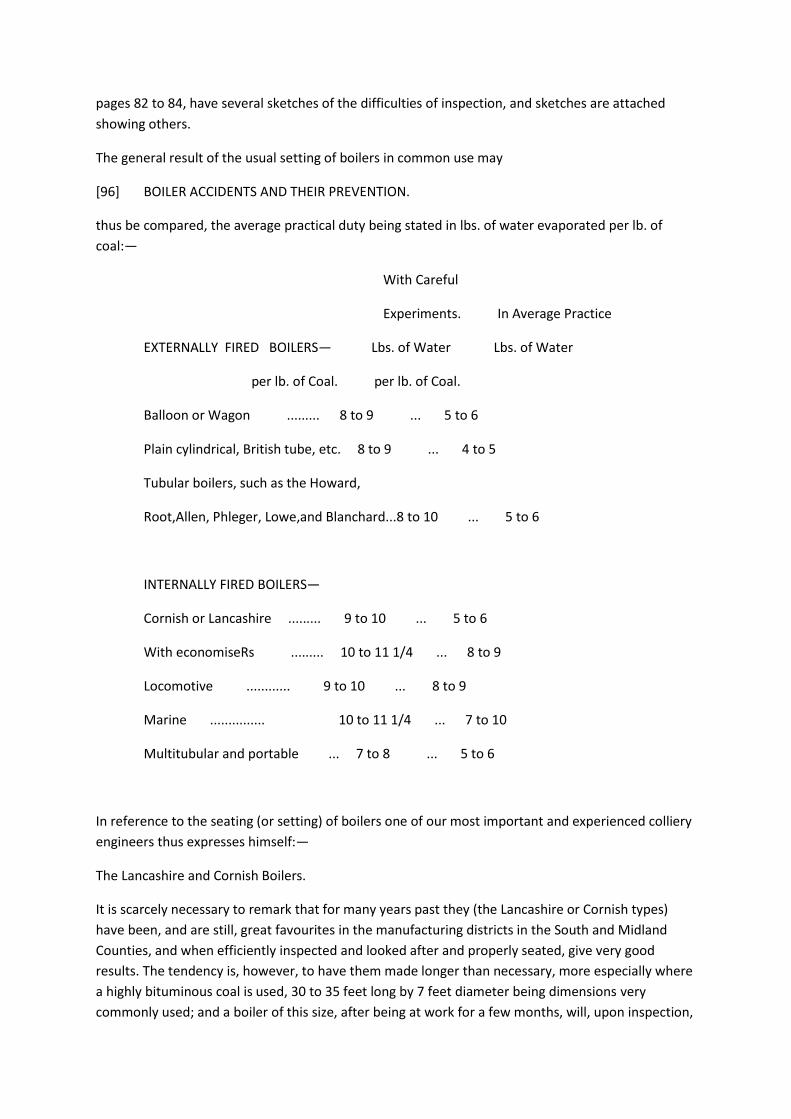
pages 82 to 84, have several sketches of the difficulties of inspection, and sketches are attached
showing others.
The general result of the usual setting of boilers in common use may
[96] BOILER ACCIDENTS AND THEIR PREVENTION.
thus be compared, the average practical duty being stated in lbs. of water evaporated per lb. of
coal:—
With Careful
Experiments. In Average Practice
EXTERNALLY FIRED BOILERS— Lbs. of Water Lbs. of Water
per lb. of Coal. per lb. of Coal.
Balloon or Wagon ......... 8 to 9 ... 5 to 6
Plain cylindrical, British tube, etc. 8 to 9 ... 4 to 5
Tubular boilers, such as the Howard,
Root,Allen, Phleger, Lowe,and Blanchard...8 to 10 ... 5 to 6
INTERNALLY FIRED BOILERS—
Cornish or Lancashire ......... 9 to 10 ... 5 to 6
With economiseRs ......... 10 to 11 1/4 ... 8 to 9
Locomotive ............ 9 to 10 ... 8 to 9
Marine ............... 10 to 11 1/4 ... 7 to 10
Multitubular and portable ... 7 to 8 ... 5 to 6
In reference to the seating (or setting) of boilers one of our most important and experienced colliery
engineers thus expresses himself:—
The Lancashire and Cornish Boilers.
It is scarcely necessary to remark that for many years past they (the Lancashire or Cornish types)
have been, and are still, great favourites in the manufacturing districts in the South and Midland
Counties, and when efficiently inspected and looked after and properly seated, give very good
results. The tendency is, however, to have them made longer than necessary, more especially where
a highly bituminous coal is used, 30 to 35 feet long by 7 feet diameter being dimensions very
commonly used; and a boiler of this size, after being at work for a few months, will, upon inspection,
be found in most cases strongly coated in the seating flues with soot, more especially towards the
exit end of the flues; and this, I believe, is caused in a great measure by the excessive distance which
the heated gases have to travel before their exit to the chimney, showing very clearly that the
temperature at these points, although considerable, was too low to support combustion, and that
little good was obtained from this part of the boiler. Following up this idea the writer has for many
years past adopted a standard length of 20 to 24 feet for single or double tube boilers, and has
found them equal to the longer boiler in efficiency; thus enabling the purchaser to have three boilers
for little more than the price of two of the longer type.
In setting boilers too much care cannot be exercised as to the form and position or direction of the
flues; and where the boiler is of moderate length it is found advantageous to have the flues returned
underneath the boiler to the front end, and back over along the sides to the chimney. Should the
boiler be of considerable length, however, this plan is not so much to be commended, owing to the
distress caused by arching to the boiler. In this case the flues ought to return along the sides first and
afterwards along the bottom to the chimney; and also means adopted for supporting or carrying the
boiler. As an instance, many people still follow the injudicious practice of building boilers in with a
large mass of brickwork, and thus invite external corrosion to a serious extent, because it (the
brickwork) has the effect of keeping any water that may
[97] BOILER ACCIDENTS AND THEIR PREVENTION.
find its way to the boiler in contact with the plates, and also prevents the detection of any waste
that may be going on; and where this state of things is allowed to continue, a rapid oxidation is
certain to take place, which ends in the destruction of the boiler in many cases before the owner is
aware of the fact. (See Figs. 3 and 4, Plate XII.)
The worst cases of this kind are where internally fired boilers are placed upon very broad side walls,
or in some cases a broad middle wall is used of about 18 inches in thickness, and in such cases it is
impossible for any inspector to tell by ordinary examination in going along the flues the condition of
the plates resting on the brickwork. It frequently happens that to all appearance the plates are in
good order until the brickwork is removed, when they are often found considerably decayed and
nearly eaten through. The proper remedy for this is to keep the side walls as narrow as possible,
consistent with the stability of the boiler, the total breadth being from 3 to 4 inches, but not more,
with a loose brick at each ring seam, to facilitate examination.
In all cases where the flues are damp it is advisable to break the contact between the boiler and the
brickwork by the use of cast-iron plates, which may be made very narrow, and carried the whole
length of the boiler. The arrangement of the brickwork at the front end of internally fired boilers is
also a frequent source of trouble by being built up too wide and encircling the sludge pipe; and
should there be any leakage here, a thing which is often found, the brickwork absorbs and holds the
moisture, causing a rapid corrosion to set in to the ultimate destruction of pipe and boiler bottom in
a very short space of time.
Cooling ashes, or permitting them to lie in contact with the plates in front of the boiler, is another
source of frequent and considerable damage. This practice ought never to be allowed, but all refuse
from ashpit, etc., should be removed as quickly as possible out of the way.
The Plain Cylinder Boiler.
The plain cylinder boiler, although inferior to the Cornish or Lancashire boiler as a steam generator,
has much to recommend it on account of its simplicity, less first cost, and economy in repairs, to say
nothing of greater freedom from explosions. Moderate lengths, say not exceeding 30 feet, ought to
be observed to prevent distress from arching, which in any case takes place to a greater or less
degree, according to circumstances; and it has come under the writer's notice repeatedly that
boilers of great length have been rent asunder on the underside from this cause alone. The old
method of setting these boilers with wheel flues has fallen into disuse, the flash flue being generally
adopted with various modifications—such, for instance, as throwing cast iron girders transversely
over the boiler to receive the suspension bolts for carrying the boiler, the said bolts being attached
to the boiler by a strong T bar or a couple of angle irons riveted on, three girders, having three bolts
each, being generally used, and in some cases volute springs have been applied under the nuts of
the suspension bolts to equalize the weight. Either of the above methods of carrying a boiler have an
advantage over the old-fashioned knee or saddle, inasmuch as they enable the weight to be
distributed over the various points of suspension after the boiler has got to work, and this is a
matter of great importance for relieving the strain upon the middle, caused by the ends coming up
under the expansion of the bottom plates. In numerous cases, too, the brickwork is closed in at or
below the centre of the boiler, with a view no doubt to prevent the possibility of the heat or flame
reaching the plates above the water level;
[98] BOILER ACCIDENTS AND THEIR PREVENTION.
this precaution has been proved by long experience to be quite unnecessary, and is a great
hindrance to the generation of steam, by exposing such a large area of plate to the atmosphere for
radiation of heat, instead of having it added to the flue for generating steam, two fire bridges being
commonly used—one immediately behind the fire, the other at the termination of the cylindrical
part of the boiler at the chimney end—such bridges being invariably about 12 inches or more from
the boiler bottom, and the intervening distance between them from 3 to 4 feet down below the top
of the bridges, and consequently offering a large area of escape for the heat without coming into
contact in any way with the plates. These and other similar mistakes have contributed in no small
degree to place the boiler in an unfavourable position in the opinion of the steam user as being as
extravagant in fuel. It has been found in practice, however, that when this boiler is properly seated
and attended to, it is capable of giving very satisfactory results, and recent improvements have gone
far to render it only slightly inferior to the more expensive kinds; and in many instances where
Young's furnace and arrangement of bridges and flues have been adopted, a net saving of 30 to 40
per cent, in fuel, and 50 per cent, in labour has been effected. The principal features in this
arrangement are (see Figs. 1 and 2, Plate XIII.)—1st, the greatly increased area of heating surface
which is obtained by the peculiar arrangement of this flue, which enables the brickwork to radiate or
throw back the heat upon the plates, which causes the boiler to act with increased efficiency; 2nd,
the increased number and position of the bridges. By this means the large area of opening over the
fire bridge is reduced to the least possible limit, and so with all the other bridges, the consequence
being that a large volume of heat is prevented from passing away to the chimney without doing any
useful work; because, however large the opening over the bridges may be, it is clear that the upper
surface only of the heat and volume will be in contact with the boiler; so that any excess of opening
over and above that which is just necessary for ensuring a good draught is a direct source of waste

and extravagance in fuel. In conjunction with this arrangement it has been found by experience
that little more than one-half the usual grate area is necessary in most cases for obtaining the same
amount of work from a boiler, hence the large saving in both fuel and labour.
The method of firing or serving these furnaces with fuel is considered to have decided advantages
over the usual doors, a couple of teeze holes being used instead, similar to the puddling or forge
furnace. Duff coal being extensively used, it is piled up in front to allow the volatile ingredients to be
distilled, and get partly coked before being pushed forward into the fire, which to some extent
prevents smoke and also the duff from being carried over the bridge into the flue. And last, though
by no means least, the cold air is prevented from rushing in upon the heated plates, thus causing
these troublesome lap-edge fractures so frequently met with and so much dreaded by those in
charge of boilers.
In concluding this third part of the subject, the writer feels the great difficulty which attends the task
he has undertaken. The mass of materials so willingly and generously placed at his disposal has
rendered it far from easy to make a judicious selection of facts, figures, or theories, and he craves
the indulgence of his readers for many imperfections and omissions. In the fourth and concluding
part it is intended to deal briefly
[99] DISCUSSION—BOILER ACCIDENTS AND THEIR PREVENTION.
with boilers per se, and also to abstract the scope of the paper; on the entirety of which the writer
trusts to evoke a discussion which will, far more than his own feeble efforts, eventually lead to
increased safety without disregarding the kindred necessity—economy.
Mr. Bunning said, that any machinery which utilized 47 per cent, of heat units of the coal must have
been very perfect and far in excess of what had usually been considered possible. Mr. Emerson
Bainbridge, in a paper read before the British Association in Sheffield, had shown that a very much
lower percentage than this was considered a very excellent result.
Mr. D. P. Morison said, that the 47 per cent, was the amount of useful effect of the coal which might
be available for the engine. Probably the total amount utilized altogether by the engine and boiler
together did not amount to 15 per cent.
Mr. W. Cochrane was surprised at the small result of 5 lbs. of water per 1 lb. of coal obtained from
Root's boiler; he had obtained as much as 10 lbs.; the class of coal used in the experiments would of
course affect the result.
Mr. S. B. Coxon asked if much difference had been observed between the results obtained from best
screened and small coal ?
Mr. D. P. Morison replied that there was no doubt best screened coal gave better results than small
coal, but that nuts had been found to be better than either. He noticed that in one experiment with
a Root's boiler 7.3 lbs. of water to 1 lb. of coal had been obtained with screened South Durham coal.
The results of the experiments given in his paper must be understood to be a rough average.

Mr. S. B. Coxon asked Mr. Morison if in testing boilers he preferred doing so with the manhole door
off, allowing the steam to escape at the pressure of the atmosphere, or whether he thought it better
to do so under pressure, and if the latter, whether the result might not be very much interfered with
from the primings which would probably take place?
Mr. Morison replied that he personally would prefer testing the boilers under the pressure they
were constructed to carry in their every day work.
Mr. T. W. Bunning stated that the Government experiments were always made at the pressure of
the atmosphere, and the records always modified to one uniform temperature of feed of 100
degrees Fahr., notwithstanding the actual temperature of the feed-water used. Theoretically, also, it
made no difference under what pressure these experiments were made, as for the purposes of
examination amongst themselves they could be
[100] DISCUSSION—BOILER ACCIDENTS AND THEIR PREVENTION.
always modified to any given standard required. Practically, however, there was less danger of the
results being vitiated by priming when they were made simply under atmospheric pressure.
Mr. J. A. G. Ross said, that from his experience it was usual to make the experiments under pressure,
and thought that the results would be more satisfactory as being obtained in the normal state of the
boiler when at work, and these results he considered would differ very considerably from those
attained simply under atmospheric pressure as the temperature of the water itself would be very
much greater, as also would be the loss of heat by radiation.
The Chairman said, that there were well-known formulae for reducing experiments taken from any
temperature of feed under any pressure to one given standard.
Mr. Morison said, that he was sorry to differ from Mr. Bunning, who had had a very great experience
in testing coals; but he quite agreed with Mr. Ross in considering that it was preferable to test the
performance of boilers while under their working pressure.
Mr. Cooke then proposed a vote of thanks to Mr. Morison for his valuable paper.
Mr. Cochrane seconded the motion, which was unanimously carried, adding that the collection of
such a mass of useful information must have given Mr. Morison a large amount of trouble, and that
the Institute was much indebted to him for the valuable addition he had made to their Transactions.
The meeting then separated.
[000 Plate VI. To illustrate Mr. D.P. Morison's paper "On boiler accidents and their prevention".
Figs. 1, Balloon & 2, Wagon]
[000 blank page]
[000 Plate VII. To illustrate Mr. D.P. Morison's paper "On boiler accidents and their prevention".
Figs. 1, Long plain cylinder, & 2, Plain cylinder]
[000 blank page]
[000 Plate VIII. To illustrate Mr. D.P. Morison's paper "On boiler accidents and their prevention".
Figs. 1 & 2, Perkins, 3, Perkins' oven, 4, Perkins, 5 & 6, Howard, 7, Homogeneous or steel boiler, 8,
Root]
[000 blank page]
[000 Plate IX. To illustrate Mr. D.P. Morison's paper "On boiler accidents and their prevention". Figs.
1, Cornish, 2, Lancashire, 3, Circular Marine, 4, Marine]
[000 blank page]
[000 Plate X. To illustrate Mr. D.P. Morison's paper "On boiler accidents and their prevention".
Chimney boiler for furnaces.]
[000 blank page]
[000 Plate XI. To illustrate Mr. D.P. Morison's paper "On boiler accidents and their prevention".
Rastrick boiler for furnaces.]
[000 blank page]
[000 Plate XII. To illustrate Mr. D.P. Morison's paper "On boiler accidents and their prevention".
Figs. 1 & 2, Lancashire boiler seatings (Hawksley, Wild & Co.'s design); Figs. 3-5, Boiler seatings -
(Young's designs)]
[000 blank page]
[000 Plate XIII. To illustrate Mr. D.P. Morison's paper "On boiler accidents and their prevention".Figs.
1 & 2, Young's furnace for plain cylinders.]
[000 blank page]
[101] PROCEEDINGS.
PROCEEDINGS.
GENERAL MEETING, SATURDAY, FEBRUARY 7th, 1880, IN THE WOOD MEMORIAL HALL, NEWCASTLE-
UPON-TYNE.
G. C. GREENWELL, Esq., in the Chair.
The Secretary read the minutes of the last General Meeting and the minutes of the Council
meetings.
The following gentlemen were elected :—
Ordinary Members —
Mr. Edward Gawler Prior, Government Inspector of Mines, Nanainis, British Columbia.
Mr. William Frederic Butler, Civil Engineer, 6, Queen Anne's Gate, Westminster, S.W.

Mr. William Ackroyd, Jun., Morley Main Collieries, Morley, near Leeds.
Student—
Mr. R. Cecil Peake, Harton Colliery Offices, South Shields.
The following was nominated for election at the next meeting :—
Student— Mr. Charles James Murton, Jesmond Villas, Newcastle-on-Tyne.
The President remarked, that the minutes of the Council meeting held that day, read by the
Secretary, stated that the President had brought forward the subject of the appointment of a mining
lecturer to the Institute. He had brought forward the question in consequence of a letter which he
had received from the North Staffordshire Institute of Mining and Mechanical Engineers, which
stated that it had long been the object
[102] PROCEEDINGS.
of those interested in that Institute to extend its usefulness by promoting the more general study of
those sciences pertaining to mining and engineering; and with this view they had arranged for
classes which they believed would be of great service to the members. The subjects would be
practical chemistry, geology, and mining engineering. The practical mining classes would include the
study of gases and other chemical phenomena found in mines, and also analyses of the different
minerals connected with mining which are of such importance in the present scientific state of the
iron and steel industries. It appeared to him that there are two classes of persons connected, or
about to be connected, with collieries; for one, the young, all the scientific instruction necessary is
already provided in the classes now so well conducted in the college and schools of this
neighbourhood; but as to the other, namely, those persons actually and practically employed in the
work of collieries— he meant overmen and others who had not either the means or the time to avail
themselves of the privileges offered in the earlier stage of life— evening instruction, such as that
contemplated by the North Staffordshire engineers, would be more valuable. He understood that it
was already in contemplation to appoint a chair for instruction in mining—such chair would give very
much such instruction as regards mining as is given to the present classes in chemistry; but it would
not be to any large extent of that description which would be desirable for the class of people of
whom he had spoken. He therefore thought that if a mining professor should be appointed,
periodical lectures should be given, and it would be desirable, if possible, that the professor should
be a practical as well as a scientific man. It was a subject of general remark, and he had regretted it
very much, that there were frequently men well able from their practical knowledge to become
managers of collieries, but who in the examination which it is necessary they should pass in order to
obtain their certificates, fail for want of the knowledge which might be imparted by such classes as
he had spoken about.
Mr. J. B. Simpson said, it was the intention of the College of Physical Science to appoint a mining
professor. The question was to be considered by the Council in the ensuing week, and probably it
would be better to allow the question to remain open until it was seen what was done by them. The
object to be obtained was the same as that which was originally intended when the college was
commenced, and which had always been kept before the Mining Institute; and he thought that the
education which would be given by the college through the professor of mining would carry out
what Mr. Greenwell's intention seemed to be, that
[103] PROCEEDINGS.
was, to give a theoretical knowledge of mining to those who had not had the benefit of education;
and, although that would not probably apply to most of the students who attended in the day time,
yet in the evenings, no doubt, the professor of mining would be able to have classes which could be
attended by overmen and others from the collieries round about. If a little time were given, the
members would see whether the course which the Physical Science College was about to take would
meet Mr. Greenwell's views on the subject.
The subject then dropped.
At the suggestion of Mr. John H. Merivale, and on the recommendation of the Council, the Secretary
was instructed to write to the Registrar-General and ask him to add the profession of "Mining
Engineers" to those already given in the results of the census of 1871, showing the occupation and
ages of people at death.
Mr. T. J. Bewick then read the following Memoir of Mr. Thomas Sopwith :—
[104 blank page]
[105] MEMOIR OF MR. THOMAS SOPWITH.
MEMOIR OF MR. THOMAS SOPWITH.
By THOS. J. BEWICK.
Thomas Sopwith, M.A., F.R.S., was born in Newcastle-upon-Tyne, on the 3rd of January, 1803, and
received his education at private schools in that town and in Gateshead.
He was first apprenticed to his father, who carried on with success a large cabinet-making and
joinery business in Newcastle, and although retaining an interest therein for many years, he did not
long continue to practically follow it. He had much taste for drawing, and became a rapid and correct
sketcher, in which he excelled all his life. He likewise devoted himself much to scientific and literary
pursuits. He rose early; was active, industrious, and persevering; and thus it was, whilst still at the
bench from early morn to late at night, he found time to study architecture and the use of optical
and philosophical instruments, in which he became proficient. Thus in 1822, when only nineteen
years of age, he designed a new gaol for his native town, and illustrated it by models and plans,
which secured for him the commendation of the authorities, and a gratuity of ten guineas was voted
to him.
On attaining manhood he, with his father's consent, left the business, to study land and mining
surveying at Alston Moor, and in this he soon made himself so competent that Mr. Dickinson, under
whom he had studied, took him into partnership.
Having made mine surveying and engineering a special study, he quickly became noted for the
correctness of his surveys, and the neatness and detail of the plans and sections which he prepared
therefrom.
During the four years he remained at Alston he, in conjunction with his partner, prepared detailed
plans and sections of the lead mines in Alston Moor, belonging to the Commissioners of Greenwich
Hospital. He was also during this period engaged in making surveys and plans for
[106] MEMOIR OF MR. THOMAS SOPWITH.
the Corporation of Newcastle and others. These occupations did not, however, prevent him
following the bent of his mind, for in 1826 he published his first book, being an account and plans of
the interior of All Saints' Church, in Newcastle-on-Tyne, and made sketches of various public
buildings and private works, the latter principally those of a mining character.
It was during this time that some etched plans and sections of the great Hudgill Burn Lead Mine,
which he had prepared, came to the knowledge of Dr. Buckland, the celebrated professor of
geology, and led to an intimacy ending only in the doctor's death.
While at Alston he made the acquaintance of the late Mr. Hugh Lee Pattinson, so well known as the
inventor of the de-silverizing process bearing his name, and a close friendship continued until the
death of Mr. Pattinson.
Having established himself as a civil and mining engineer in Newcastle, he soon found much
occupation in the profession he had adopted. In 1830 he surveyed and levelled a new road between
Newcastle and Otterburn, and was consulted by many of the county gentry on various matters
affecting their estates.
In 1832 he entered upon new offices in the Royal Arcade, which he continued to occupy until 1845,
when he received the appointment of chief agent of the W. B. Lead Mines in Northumberland and
Durham.
In these thirteen years he was occupied professionally on many local undertakings, such as the new
streets and improvements of Newcastle, carried out by Mr. Richard Grainger; the coal and iron
mines of the Forest of Dean, of which he made detailed surveys, and prepared sections, and a model
of the entire Forest, showing the beds of coal and workings therein, and reported thereon to the
Woods and Forests Department of the Government; the Newcastle and Carlisle, the Great North of
England, the Newcastle and Berwick, the London and Brighton, and other railways in England, as well
as the Sambre and Meuse Railway in Belgium; a road from Newcastle to Shotley Bridge, and an
extension to Middleton-in-Teesdale; works connected with the improvement of the River Tyne; and
many others of a similar but less extensive character. Whilst occupied on these undertakings he
made the acquaintance of many eminent men, professional and otherwise. Amongst others may be
named the late Messrs. George and Robert Stephenson, Mr. John Buddle, Mr. Nicholas Wood, Mr.
Richard Grainger, Sir William Cubitt, Mr, I. K. Brunel, Mr. J. M. Rendel, and Mr. Bryan Donkin.
After 1845, although not taking an active part publicly in the pro-
[107] MEMOIR OF MR. THOMAS SOPWITH.

fession, he yet, in conjunction with the late Mr. Marcus Scott, his brother-in-law, and Mr. T.
Macdougall Smith, carried on an extensive practice as civil and mining engineers in London.
Having previously been engaged in connection with the mines of the Forest of Dean, he was, under
the Act 1 and 2 Vict., c. 43, for regulating the opening and working of mines and quarries in the
Forest of Dean, in the County of Gloucester, which received the Royal assent on 27th July, 1838,
appointed by the Government Commissioner on behalf of the Crown, his colleagues being John
Probyn, Esq., of Gloucester, selected by the Free Miners, and John Buddle, Esq., the eminent colliery
viewer, who was the third Commissioner or Umpire.
The inquiry extended over three years, and in July, 1841, the Commissioners made their award,
which, by order of Her Majesty's Commissioners of Woods, Forests, and Land Revenue, was in the
same year published, and the task of preparing the award and accompanying map for publication
devolved on Mr. Sopwith.
On frequent subsequent occasions Mr. Sopwith acted professionally for the Government in
connection with Crown properties.
From 1845 to 1871, a period of twenty-six years, Mr. Sopwith was chief agent of the W. B. Lead
Mines, belonging to the Beaumont family, the representative of which is, and was during the greater
part of Mr. Sopwith's connection therewith, Wentworth Blackett Beaumont, Esq., M.P. The first
twelve years of this period Mr. Sopwith resided almost constantly at Allenheads, and here, in the
midst of the workmen and their families, he was ever busy in promoting the interests of his
employer, but in so doing did not forget the well-being of those acting under him, whether as agents
or workmen. He took great interest in the comfort of those around him, and in the education of the
children whose parents were dependent on the industry over which he presided. In these matters he
found in Mr. Beaumont a zealous and liberal chief. The houses were improved, and many new ones
built, with due regard to the health and comfort of the inmates. Several schools were erected in the
various districts comprised within the limits of the vast property of which Mr. Sopwith had charge.
These schools were open to all denominations alike, and the mode of teaching religious lessons, as
carried out at these schools, was shown by Mr. Sopwith in evidence given by him before a
Parliamentary Committee, when he illustrated the various lessons a teacher might give from the
19th Psalm. The children were made to think, and every writing lesson was a useful piece of
information; punctuality was constantly enforced, and a system, which Mr. Sopwith
[108] MEMOIR OF MR. THOMAS SOPWITH.
called " drill arithmetic," was successfully carried out. Object lessons, freehand and geometrical
drawing, grammar, composition, geography, and, not least, the importance of punctuality,
integrity,and good conduct in every relation of life, were seduously enjoined and constantly
illustrated and enforced.
In addition to the schools, miners' rooms were erected, libraries and news rooms established, and
benefit societies formed at the different centres on a larger scale than had previously been
attempted, all of which tended greatly to the comfort and improvement of the workmen and others.
After 1857 Mr. .Sopwith lived in London, but still acted as Mr. Beaumont's chief mining agent.
Although less frequently present amongst the workmen, he continued up to his retirement in 1871
to take the same lively interest in the well-being of the people, and devoted much time to their
social welfare.
In June, 1871, after holding the appointment twenty-six years, Mr. Sopwith resigned his office of
chief agent at the W. B. Lead Mines, and retired from the active duties of the profession, having
been engaged in it just half a century.
On his retirement he was entertained at a complimentary dinner, and presented by the agents and
workmen of the W. B. Lead Mines and others with a handsome service of plate, " as a testimonial of
their respect and esteem of his skill and integrity in the discharge of his duties during a period of
twenty-six years; and also to mark their appreciation of his zealous efforts in promoting education
and other benevolent objects." At the same time he was presented with a lengthy address from the
workmen, testifying to the great interest he had ever evinced towards them and their families, and
expressing in warm terms their gratitude and thankfulness, and their regret that his retirement from
the active duties of his profession was the end of a beneficial supervision, and the breaking of the
close link which had existed between them for over a quarter of a century.
Mr. Sopwith was the author of several books and papers. Amongst them may be mentioned " A
Historical and Descriptive Account of All Saints' Church in Newcastle-upon-Tyne," published in
February, 1826, when Mr. Sopwith had only just completed his twenty-third year ; " An Account of
the Mining Districts of Alston Moor, Weardale, and Teesdale," published at Alnwick in 1833; and in
the following year was issued his largest work on " Isometrical Drawing," which went through several
editions. Besides these Mr. Sopwith was the author of some books on travel, educational and other
subjects, and not unfrequently contributed articles to magazines and newspapers.
[109] MEMOIR OF MR. THOMAS SOPWITH.
On the occasion of the British Association meeting in Newcastle-on-Tyne in 1838, Mr. Sopwith took
an active part in promoting its success, and contributed six papers on various subjects, one of which
was " Suggestions on the Practicability and Importance of Preserving National Mining Eecords,"
which led to the appointment of a Committee of the Association, consisting of the Marquis of
Northampton, Sir Charles Lemon, Bart., Mr. Buddle, and Mr. Sopwith, which succeeded in inducing
the Government to take up the subject, and resulted in the establishment of the present
department for Mining Records at the Museum of Practical Geology, in Jermyn Street, London.
When the British Association assembled in Newcastle for the second time, in 1863, Mr. Sopwith was
again active in securing its success. He was one of the secretaries of the Geological Section ;
contributed a paper on " A Section of the Strata from Hownes Gill to Cross Fell;" and, in conjunction
with the late Mr. Thomas Richardson, prepared the report " On the Local Manufacture of Lead,
Copper, Zinc, Antimony, &c." On this occasion one of the excursions of the members of the
Association was to Allenheads, when in spite of a pouring rain a day of great interest and enjoyment
was experienced, in which Mr. Sopwith took a prominent part.
In May, 1833, Mr. Sopwith was elected a member of the Institution of Civil Engineers, and at his
death there were only twelve members on the list who had been elected at an earlier date. In the
proceedings he took much interest, was a member of the Council in 1846, 1847, and 1848, and

occasionally took part in the discussions at the weekly meetings of the Institution, the last occasion
on which he addressed the members being within a few weeks of his death.
On the 5th June, 1845, he was elected a Fellow of the Royal Society, and in 1857 had conferred upon
him the honorary degree of M.A. by the Senate of the University of Durham. He was also from 1845
a Fellow of the Society of Arts, and from 1858 to 1863 was on the Council; a Fellow of the Geological
Society and other kindred institutions, and to all, or nearly all, the societies with which he was
connected he contributed papers. He took a warm interest in local institutions, and actively
promoted lectures to the working classes, and exhibitions of works of art and industry in his native
town.
Of our own Institute he became a member in 1853 and continued until 1877, when, living as he then
was far from the scenes of our labours, he retired, leaving his only sons (Mr. Thomas Sopwith and
Mr. Arthur Sopwith) on the list of membership. He contributed in 1865 a paper on " The Lead Mining
Districts of the North of England."
[110] MEMOIR OF MR. THOMAS SOPWITH.
Amongst Mr. Sopwith's intimate friends, are to be numbered Professors Buckland, Sedgwick,
Conybeare, John Philips, Faraday, and Pillans, George and Robert Stephenson, Robert and William
Chambers, Sir Roderick Murchison, Sir Francis Chantrey, Charles Babbage, John Buddie, Sir William
Cubitt, and Mary Somerville the authoress, with each of whom he carried on friendly and scientific
correspondence.
He had considerable mechanical and geological knowledge, and in the latter more particularly was
frequently consulted on important matters, whilst in the former he was the inventor of the
Telescopic Levelling Stave and the Monoclied Cabinet, an ingenious and admirable arrangement of
writing desk and drawers combined under one key. He likewise designed the series of geological
models, now so well known by students and others, constructed of different coloured woods as
representing various beds of rock, and showing with extreme clearness the effect resulting from
dislocations, denudation, etc. An excellent model of the Forest of Dean, showing the surface and the
more important beds of coal, was prepared from the designs and under the direction of Mr. Sopwith
for the Commissioners of Woods and Forests, and is now placed in the Museum of Practical Geology
in London. Somewhat similar models were constructed by Mr. Sopwith of the Ebbw Vale and
Sirhowy Iron Company's property and mines of coal and iron in Monmouthshire, and of lead and
other mines in different parts of the country.
The well-known hydraulic machinery for pumping, winding, crushing, and other purposes at the W.
B. Lead Mines was designed and erected by Sir W. G. Armstrong, acting under Mr. Sopwith's
instructions.
Mr. Sopwith entered on his career when the engineering profession was, it may be said, in its
infancy. The Stockton and Darlington Railway was opened when he was twenty-two, and the
Liverpool and Manchester line before he had attained his twenty-seventh year. It was not however
railways to which he especially devoted his attention : from the first he appears to have laid out a
course for himself which eventually placed him in the front rank of metalliferous mining engineers.
Great industry, exactness in details, clearness of expression, methodical to a fault, and conscientious
in all his transactions, were characteristic of Mr. Sopwith. He was a fluent speaker and a ready and
precise writer, as is proved by his journals, which consist of 168 volumes, containing interesting
descriptions of places and people, interspersed with numerous and amusing pen-and-ink sketches
which would do credit to a professional artist. This journal was begun when he was eighteen years of
age, and continued to within a fortnight of his death, a period of fifty-eight years, with the same
characteristic neatness and exactness.
[111] MEMOIR OF MR. THOMAS SOPWITH.
Up to within a few months of his death, which occurred at his residence in London, on the 16th of
January, 1879, at the age of 76, Mr. Sopwith enjoyed excellent health. He was fond of travelling, and
visited many places on the Continent; and few localities of interest in the British isles were unknown
to him. With his natural flow of high spirits, conversational powers, and well-stored and retentive
memory, he was a genial companion and a good friend, and will long be remembered with feelings
of satisfaction by those whose advantage it was to have the pleasure of his acquaintance.
The writer's connection with Mr. Sopwith dates from January, 1836 ; he served his articles of
apprenticeship with him, and continued as his assistant until 1846, from which time until 1866 he
acted under him as engineer of the W. B. Lead Mines, and subsequently a more or less close
professional and friendly intercourse continued to exist up to Mr. Sopwith's decease.
Much of the preceding is within the writer's personal knowledge, but he has in addition been greatly
indebted to a memoir of Mr. Sopwith, published in the Transactions of the Institution of Civil
Engineers, recently issued, and from which, with the permission of the writer, he has freely copied,
and for which he heartily offers his acknowledgments.
Mr. Steavenson thought that the meeting would agree with him that their time had been well spent
in listening to the record of a useful life such as had just been so attractively described by Mr.
Bewick, and he had great pleasure in moving a vote of thanks to that gentleman.
Mr. Cooke seconded the motion, which was unanimously carried.
The following papers were then read :—" Notes on the Mueseler Lamp," by Mr. A. R. Sawyer, and
"Improved Safety-lamps on the Davy and Mueseler Types," by Mr. James Ashworth.
As these papers contain many allusions to the Mueseler lamp, it has been thought advisable to print
a translation of a report of a committee
[112] PROCEEDINGS.
nominated in Belgium by Ministerial decree the 20th January, 1867, the powers of which were
enlarged by another decree dated 20th January, 1868, which was published in the year 1873, and

also a translation of the royal decree concerning safety-lamps bearing date 17th June, 1876, which
have obligingly been placed at the disposition of the Institute by Mr. C. G. Jackson, of Wigan.
[113] SAFETY-LAMPS FOR MINES.
SAFETY-LAMPS FOR MINES.
Report of the Commission instituted in Belgium by Ministerial Decree dated the 20th of January,
1868.
By a decree dated the 16th of April, 1867, the Minister of Public Works appointed a Commission of
Engineers to examine whether it was advisable to allow the use of certain safety-lamps fed with
petroleum oil for the lighting of fiery mines.
This Commission had commenced its report, when, in 1868, in consequence of experiments made in
England on mining lamps placed in explosive currents moving at a high velocity, the Minister
enlarged the scope of the Commission by a decree dated the 20th of January, intrusting it with the
examination and comparison of the various lighting apparatus, including those which were already in
use in mines as well as those which had been recently proposed, whether fed with vegetable or
mineral oil. The members of the Commission were also finally selected at the same time.*
The enlargement of the programme caused the presentation for trial of a very large number of
lighting apparatus. A Sub-Commission was named from the Commission itself for the purpose of
proceeding with such preliminary experiments as would justify a preparatory elimination. Several
events interrupted the labours of the Commission: they were resumed in 1872, and resulted in a
numerous series of experiments; these experiments, as well as those undertaken in 1868 by the Sub-
Commission, took place at one of the gas-works in Liege.
The circumstances and results of the experiments are recorded in the detailed tables published
afterwards, which tables should be considered as having to some extent guided the Commission in
their report. To these
* After various changes it was in the end composed of:—MM. Jochams, Inspector General of Mines,
President; Trasenster, Professor at the University of Liege, Vice-President; Laguesse and Van
Scherpenzeel-Thim, Chief Engineers; Chandelon, Professor at the University of Liege; Lambert,
Principal Engineer; E. Mockel, Director of Coal Mines; Harze, Engineer, Secretary; Schorn, Engineer,
Assistant Secretary.
[114] BELGIAN RBPORT ON
tables are added a descriptive table of the lamps, and some sketches; the latter, although not
indicating the details of the working of the different parts, are, nevertheless, quite sufficient to show
the character of the proposed innovations.
The apparatus used for the experiments, which it is not necessary here to describe in detail,
consisted of a box-gallery of wood in which the lamps were placed to be tried; one of the sides was
pierced with apertures furnished with thick glasses which allowed all that was going on inside to be
seen. A centrifugal fan driven by a steam engine caused a rapid current of air in the box-gallery, into
which, at any given moment, the illuminating gas, coming from a gasometer specially reserved for
the experiments of the Commission, could be introduced. An hydraulic valve served to introduce,
stop, and regulate the emission of the gas. The box-gallery was shut up in a dark chamber in order
that the phenomena in all their details might be better observed; the lever by means of which the
valve was worked was placed in the interior of this chamber.
The action of the machine could be very easily regulated so as to obtain currents of a very
appreciably uniform velocity during the period of a series of experiments. This uniformity was
confirmed by numerous observations by means of Biram's and Dickinson's anemometers; the latter
particularly being able to be used easily and quickly, was employed at frequent intervals to control
the working of the engine.
Concerning the composition of the mixture, special experiments were made to approximately
determine the proportions of gas corresponding to different openings of the valve. These
experiments gave the following results for a velocity of six metres of the mixture :—
[table]
The experiments were generally made with mixtures moving at a velocity of about 19.68 feet per
second, a velocity known to be dangerous for the ordinary Mueseler lamp, whilst a velocity of from
9.84 to 13.12 feet has in almost every case been found safe.
[115] SAFETY-LAMPS FOR MINES.
In order to study in as complete a manner as possible all the phenomena which these lighting
apparatus may exhibit under all the different circumstances attendant on their habitual use, and to
report with some certainty upon the degree of confidence that can be attached to the different
systems of apparatus, the Commission introduced into the experiments certain exceptional tests and
conditions, viz.:—
Firstly—Continuing the experiment as long as possible, that is to say, during five or six minutes; the
quantity of gas enclosed in the gasometer would not permit of this time being exceeded when the
speed of the current was about 19.68 feet. When the Mueseler lamp was placed in an explosive
current of this velocity, it was remarked that after the extinction of the wick the gas continued to
burn under the horizontal gauze; and it was feared that this combustion prolonged for a certain time
would cause the horizontal gauze to become red hot, and by that means pass the flame to the
outside; nevertheless, few explosions were produced by experiments of this kind, and it may be said
that the excessive prolongation of the action of rapidly explosive mixtures upon the Mueseler lamp
is not, by itself, a positive cause of explosion.
Secondly—Covering the horizontal gauze of the lamps with oil and sprinkling it over with, fine coal
dust, to imitate the condition of a lamp which has been upset and either has not been extinguished
by the fall, or when extinguished has been relit by a careless person. It was ascertained that the
lamps, when in this state, pretty easily produced explosions, especially when the explosive current
was moving at a high speed.
Thirdly—By subjecting the lamps experimented on to motion, as the lamps of workmen, when
moving about in the workings of the mine, are often subjected to more or less rough and violent
oscillations, according to the degree of precaution of the persons who carry them. Some
experiments tried on this effect have made it obvious that the safety of the lamp is diminished by
moving it to and fro, particularly in the case where a lamp which oscillates is suddenly surrounded by
an explosive mixture.
Fourthly—It was observed in some experiments that variations in the proportions of the gaseous
mixture seemed to have facilitated the passage of the flame to the exterior of the lamp ; the
Commission were thus led to vary the admission of gas by a studied manipulation of the valve,
designated in the tables by the sign "Sch," and which may be thus described. The lamp was first put
out by means of a sufficiently strong mixture of gas, which was maintained for several seconds, to
heat the metallic parts. The influx of gas was then gradually diminished nearly to the point where
the mixture ceased to be combustible; when ordi-
[116] BELGIAN REPORT ON
narily, at this moment, either the lamp was totally extinguished, or the flame passed up the chimney
into the wire gauze cylinder. In the latter case, the explosion was inevitable, particularly if at this
moment the proportion of gas was a little augmented. This succession of circumstances, however
artificial it may appear at first sight, can very well occur in mines, where the composition of the
gaseous mixtures in circulation is far from being uniform. Eelatively frequent explosions have been
obtained by this manoeuvre, more or less varied according to circumstances and the class of lamp
submitted to experiment. It may be concluded for that reason that mixtures containing very little gas
facilitate the passage of the flame up the chimney, a fact which is explained, besides, by the small
quantity of carbonic acid produced by the combustion of the mixture in the glass cylinder.
Fifthly—The Commission also judged it useful to observe the effect produced on the lamps by
inclined currents, either ascending or descending. From want of time, they were not able to make
use of the arrangement which had been resolved upon for this purpose; in place of which they made
use of a small apparatus that they introduced into the box; it was composed of two small parallel
boards, inclined to the horizon at an angle of about 30°, and each pierced with an elliptical opening
to insert the lamp. This apparatus produced not only the inflection of the current but whirlings, the
existence of which was shown by the oscillations of the flame. It is without any doubt that the
disastrous results of experiments of this kind are due to these whirlings, for not one lamp prevented
explosion when they were present; and from the observed results, it may be admitted that the
employment of the apparatus with inclined currents had the effect of completely changing the
action of the combustion in the lamps, the gaseous mixture arriving upon the flame down the
chimney, whilst the products of combustion passed away through the horizontal gauze ; also that
the whirlings, which are produced when a rapid current of air issues out of a cutting or staple, comes
rushing into a gallery, create an eminently dangerous combination if the current is more or less
charged with gas, and, therefore, miners cannot use too much caution in approaching places where
such currents are likely to occur.
Plates Nos. XIV. to XVIII. show the different systems of lamps that have been tried, and the detailed
results of the experiments are given.*
* In the original report there are ten pages of tables descriptive of the various lamps which it has not
been thought necessary to publish here. Extracts, however, have been made from them and added
to the drawings.

[117] SAFETY-LAMPS FOR MINES.
Certain lamps which exploded too easily, and certain others which burned badly and were not of a
practical construction, were only subjected to a limited number of experiments.
The experiments, as a whole, proved that no lighting apparatus can be considered as absolutely safe.
As far as the Davy and Deputies lamps are concerned, it has been observed from the beginning that
they give no kind of security in explosive currents moving at a velocity of 7.380 feet per second.
Besides, the Commission of St. Etienne had already ascertained that these lamps ceased to be safe in
an explosive current moving at a speed of 5.576 feet per second. The Commission therefore
employed these lamps when they desired to produce explosions, and also when they wished to
ascertain the composition of the mixtures.
The Mueseler lamp, whether made according to the standard or not, generally comported itself well;
however, in several cases it produced explosions the determining causes of which were not well
known ; the special manoeuvre "Sch" of the valve, the greasing of the horizontal gauze, swinging,
and the ascending whirling currents, also caused it to explode. It was observed that the safety of this
lamp rests above all in the narrowness of the top of the chimney, the diameter of which it is
advisable to diminish as much as the requirements of practice permit.
Among the various systems derived from the Mueseler type, the lamps, Godin Gr. and Joassin, were
the only ones which have passed through nearly all the experiments without explosion. The first
produces little light, compared to the Mueseler, on account of the wire gauze cone which surrounds
the flame; by its resistance to the different causes of explosion, and by the persistence with which it
preserves its light in explosive mixtures, it may be considered as a good safety-lamp, in cases where
it is necessary to penetrate into works where fire-damp exists; but unfortunately it has been
observed that this lamp occasions explosions in inclined and whirling currents, either ascending or
descending.
Of all the lamps submitted to the experiments, the Mueseler-Joassin lamp has comported itself the
best; the ascending and whirling currents, combined with the manoeuvre "Sch" of the valve, alone
being able to make it fail. But these are the most dangerous circumstances to which a lighting
apparatus can be exposed.
Independently of the lamps presented by different inventors, the Commission, acting upon the
experience acquired in the course of their work, endeavoured to produce several modifications in
the details of the Mueseler lamp ; these modifications have been more particularly modifications in
the diameter of the top of the chimney, as well as in its shape at the base, and in the distance
between the base and the wick tube.
[118] BELGIAN REPORT ON
It was observed, as it has already been said, that the narrowness of the upper part of the chimney
constitutes a great guarantee of safety, in the Mueseler lamp and in the lamps of which it forms the
type ; also that the existence or non-existence of a bell-mouthing at the base of the chimney, as well
as a difference of a few hundredth parts of an inch in the height at which the chimney is placed
above the wick tube, does not essentially modify the safety of the lamp; there is however a shade in
favour of the standard chimney.
Another modification consisted in the division of the upper part of the chimney into several
channels, in order to obtain a total section sufficient for the escape of the products of combustion,
combined with escape orifices of a very small diameter. M. Demanet (who submitted a lamp of this
type) agreed with the Commission that this arrangement did not produce any useful results in the
inclined and whirling currents.
The Commission also made some tests to ascertain the influence which the nature of the wire gauze
had upon the rapidity of the transmission of the flame. These experiments, made by means of the
Deputies lamps, did not always give precise results, the explosions in every case taking place in a
very short time; nevertheless, the period during which a gauze resisted the explosive influences
increased in proportion to the thickness of the wire and the smallness of the mesh.
The lamps submitted to the different experiments were provided either with ordinary glasses or
crystal glasses, both furnished by the establishment of Val St. Lambert. The crystal glass cylinders did
not resist the overheating any better than those of glass ; the fractures which manifested
themselves were besides more irregular, and, consequently, more dangerous than those in the
ordinary glasses. But it is to be remarked that, whatever the material employed in the manufacture
of these glass cylinders might be, the Commission, in the course of numerous experiments, never
had a case of explosion due to their rupture, the fragments after fracture remaining in all cases
secure in the sockets.
In concluding this report, it was observed that, on account of the short length of the testing box, the
gas at its arrival in the lamp, was never in a state of intimate mixture with the air; and it was shown
that the state of the atmosphere, the temperature, and degree of humidity of the air, the
composition of the gas, its more or less recent make, etc., etc., were some of the causes which may
have had an influence on the variation of the results obtained. The dangerous moment of the
exposure of a lamp being followed either by an explosion outside the lamp, or by its total extinction,
produced by a turning round of the flame, or by a small interior explosion, it may be comprehended
that the smallest difference in
[119] SAFETY-LAMPS FOR MINES.
the circumstances under which the experiments were made, or the sudden interposition of the
slightest current of air of whatever sort, suffices to make a variation in the result. Hence the
necessity of the numerous experiments which had been made, and which would from necessity
form an important part of the experience upon which the Commission would have to base its
judgment.
SECTION I.
The Davy lamps, Fig. 1, Plate XIV., experimented upon were of the following makes, viz.:—French,
used in the district of Mons, by Dubrulle, Lille; English, and one with a double gauze and interior
glass.
The lamps called "Deputy, or testing lamps," Fig. 2, Plate XIV., were of the following makes, viz.:—
Charleroi, with simple gauze, used in the district of Mons, with double gauze Mueseler Liege type,
without the chimney, and an English Clanny lamp.

On these lamps the Commissioners observed "that the Davy and deputy lamps, when exposed for
two minutes to an explosive mixture of air and lighting gas, moving at a velocity of 4.264 feet per
second, do not communicate the flame to the exterior, but when the velocity reaches or surpasses
7.380 feet the explosion is always produced on the outside, save in quite exceptional cases of
extinction by asphyxia, caused by the voluntary admission of a large quantity of gas. The Commission
did not endeavour to find out at what velocity between 4.264 feet and 7.380 feet the phenomenon
of exterior combustion commences to manifest itself; but it has been observed that the explosion
takes place after from five to ten seconds when the velocity is 9.840 feet; and after from two to five
seconds when the speed is 19.680 feet. Sometimes, at the latter speed, the explosion seems
instantaneous. The Davy lamps of the district of Mons, provided with a fine wire gauze (1,354
meshes to the square inch, and wire of .01 of an inch in diameter), and the Deputy's lamp of the
same place, having a double gauze of 1,354 meshes to the square inch, occasioned, during the
experiments of the Sub-Commission, ten cases of explosion out of ten experiments, at a velocity of
13.120 feet. In recent experiments made at St. Etienne with the Charleroi Deputy lamp, having a
simple gauze of 1,354 meshes to the square inch, and wire .01 inch in diameter, it was found that
they were safe only in a velocity not exceeding 5.576 feet."
Included in Section I. is the Singing lamp of Dr. Irvin, Fig. 3, Plate XIV., of English make, consisting of a
bronze chimney, furnished with a glass disc, and terminated by an apparatus (kind of chimney),
which,
[120] BELGIAN REPORT ON
in case of the combustion of a certain proportion of gas, causes more or less sonorous vibrations.
The air is admitted through two gauzes, one of which is under the wick-tube in a horizontal position ;
and the products of combustion pass out through a small cylinder of wire gauze which surrounds the
upper part of the chimney.
The result of the tests made by the Commission in velocities of 4.264 feet and 9.840 feet was an
explosion in the latter case; and they observed that this lamp only produced its harmonic alarm
sometime after the appearance of the flame had indicated the presence of a large quantity of gas;
and even whilst it was burning, the gauze cylinder of a Deputy's or testing lamp was full of flame. At
the second experiment it exploded before the warning noise was heard.
SECTION II.
The lamps tested were :—
The Liege Mueseler, made according to the Ministerial Decree of July 10, 1851.
Liege Mueseler, samples A and B, from the Coal Mines of La Haye.
Do. from the Coal Mines of Marihaye.
Do. shortened .197 ins. at the base, from the Coal Mines of Marihaye.
Hainaut Mueseler, Mons district, from the Coal Mines of l'Agrappe.
Do. Do. old type of the Sub-Commission.
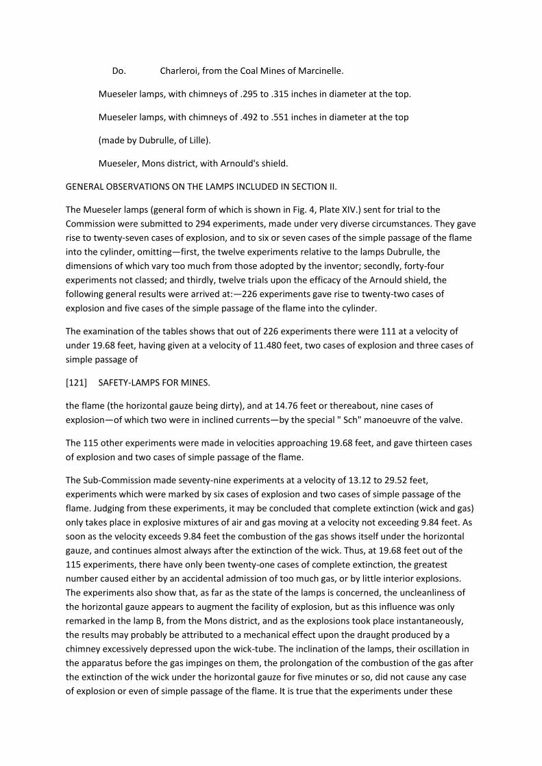
Do. Charleroi, from the Coal Mines of Marcinelle.
Mueseler lamps, with chimneys of .295 to .315 inches in diameter at the top.
Mueseler lamps, with chimneys of .492 to .551 inches in diameter at the top
(made by Dubrulle, of Lille).
Mueseler, Mons district, with Arnould's shield.
GENERAL OBSERVATIONS ON THE LAMPS INCLUDED IN SECTION II.
The Mueseler lamps (general form of which is shown in Fig. 4, Plate XIV.) sent for trial to the
Commission were submitted to 294 experiments, made under very diverse circumstances. They gave
rise to twenty-seven cases of explosion, and to six or seven cases of the simple passage of the flame
into the cylinder, omitting—first, the twelve experiments relative to the lamps Dubrulle, the
dimensions of which vary too much from those adopted by the inventor; secondly, forty-four
experiments not classed; and thirdly, twelve trials upon the efficacy of the Arnould shield, the
following general results were arrived at:—226 experiments gave rise to twenty-two cases of
explosion and five cases of the simple passage of the flame into the cylinder.
The examination of the tables shows that out of 226 experiments there were 111 at a velocity of
under 19.68 feet, having given at a velocity of 11.480 feet, two cases of explosion and three cases of
simple passage of
[121] SAFETY-LAMPS FOR MINES.
the flame (the horizontal gauze being dirty), and at 14.76 feet or thereabout, nine cases of
explosion—of which two were in inclined currents—by the special " Sch" manoeuvre of the valve.
The 115 other experiments were made in velocities approaching 19.68 feet, and gave thirteen cases
of explosion and two cases of simple passage of the flame.
The Sub-Commission made seventy-nine experiments at a velocity of 13.12 to 29.52 feet,
experiments which were marked by six cases of explosion and two cases of simple passage of the
flame. Judging from these experiments, it may be concluded that complete extinction (wick and gas)
only takes place in explosive mixtures of air and gas moving at a velocity not exceeding 9.84 feet. As
soon as the velocity exceeds 9.84 feet the combustion of the gas shows itself under the horizontal
gauze, and continues almost always after the extinction of the wick. Thus, at 19.68 feet out of the
115 experiments, there have only been twenty-one cases of complete extinction, the greatest
number caused either by an accidental admission of too much gas, or by little interior explosions.
The experiments also show that, as far as the state of the lamps is concerned, the uncleanliness of
the horizontal gauze appears to augment the facility of explosion, but as this influence was only
remarked in the lamp B, from the Mons district, and as the explosions took place instantaneously,
the results may probably be attributed to a mechanical effect upon the draught produced by a
chimney excessively depressed upon the wick-tube. The inclination of the lamps, their oscillation in
the apparatus before the gas impinges on them, the prolongation of the combustion of the gas after
the extinction of the wick under the horizontal gauze for five minutes or so, did not cause any case
of explosion or even of simple passage of the flame. It is true that the experiments under these
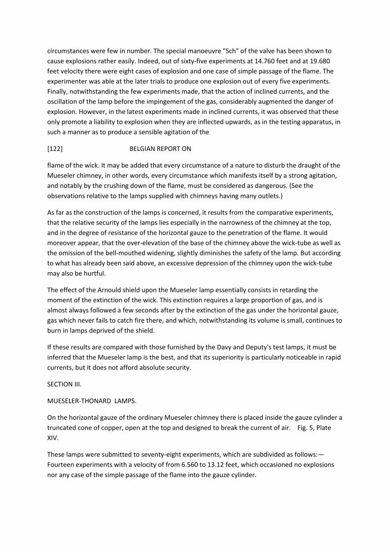
circumstances were few in number. The special manoeuvre "Sch" of the valve has been shown to
cause explosions rather easily. Indeed, out of sixty-five experiments at 14.760 feet and at 19.680
feet velocity there were eight cases of explosion and one case of simple passage of the flame. The
experimenter was able at the later trials to produce one explosion out of every five experiments.
Finally, notwithstanding the few experiments made, that the action of inclined currents, and the
oscillation of the lamp before the impingement of the gas, considerably augmented the danger of
explosion. However, in the latest experiments made in inclined currents, it was observed that these
only promote a liability to explosion when they are inflected upwards, as in the testing apparatus, in
such a manner as to produce a sensible agitation of the
[122] BELGIAN REPORT ON
flame of the wick. It may be added that every circumstance of a nature to disturb the draught of the
Mueseler chimney, in other words, every circumstance which manifests itself by a strong agitation,
and notably by the crushing down of the flame, must be considered as dangerous. (See the
observations relative to the lamps supplied with chimneys having many outlets.)
As far as the construction of the lamps is concerned, it results from the comparative experiments,
that the relative security of the lamps lies especially in the narrowness of the chimney at the top,
and in the degree of resistance of the horizontal gauze to the penetration of the flame. It would
moreover appear, that the over-elevation of the base of the chimney above the wick-tube as well as
the omission of the bell-mouthed widening, slightly diminishes the safety of the lamp. But according
to what has already been said above, an excessive depression of the chimney upon the wick-tube
may also be hurtful.
The effect of the Arnould shield upon the Mueseler lamp essentially consists in retarding the
moment of the extinction of the wick. This extinction requires a large proportion of gas, and is
almost always followed a few seconds after by the extinction of the gas under the horizontal gauze,
gas which never fails to catch fire there, and which, notwithstanding its volume is small, continues to
burn in lamps deprived of the shield.
If these results are compared with those furnished by the Davy and Deputy's test lamps, it must be
inferred that the Mueseler lamp is the best, and that its superiority is particularly noticeable in rapid
currents, but it does not afford absolute security.
SECTION III.
MUESELER-THONARD LAMPS.
On the horizontal gauze of the ordinary Mueseler chimney there is placed inside the gauze cylinder a
truncated cone of copper, open at the top and designed to break the current of air. Fig. 5, Plate
XIV.
These lamps were submitted to seventy-eight experiments, which are subdivided as follows:—
Fourteen experiments with a velocity of from 6.560 to 13.12 feet, which occasioned no explosions
nor any case of the simple passage of the flame into the gauze cylinder.
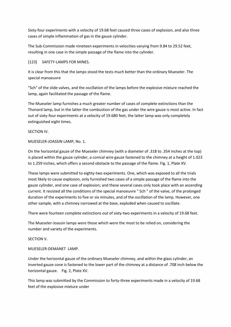
Sixty-four experiments with a velocity of 19.68 feet caused three cases of explosion, and also three
cases of simple inflammation of gas in the gauze cylinder.
The Sub-Commission made nineteen experiments in velocities varying from 9.84 to 29.52 feet,
resulting in one case in the simple passage of the flame into the cylinder.
[123] SAFETY-LAMPS FOR MINES.
It is clear from this that the lamps stood the tests much better than the ordinary Mueseler. The
special manoeuvre
"Sch" of the slide valves, and the oscillation of the lamps before the explosive mixture reached the
lamp, again facilitated the passage of the flame.
The Mueseler lamp furnishes a much greater number of cases of complete extinctions than the
Thonard lamp, but in the latter the combustion of the gas under the wire gauze is most active. In fact
out of sixty-four experiments at a velocity of 19.680 feet, the latter lamp was only completely
extinguished eight times.
SECTION IV.
MUESELER-JOASSIN LAMP, No. 1.
On the horizontal gauze of the Mueseler chimney (with a diameter of .318 to .354 inches at the top)
is placed within the gauze cylinder, a conical wire gauze fastened to the chimney at a height of 1.023
to 1.259 inches, which offers a second obstacle to the passage of the flame. Fig. 1, Plate XV.
These lamps were submitted to eighty-two experiments. One, which was exposed to all the trials
most likely to cause explosion, only furnished two cases of a simple passage of the flame into the
gauze cylinder, and one case of explosion; and these several cases only took place with an ascending
current. It resisted all the conditions of the special manoeuvre " Sch " of the valve, of the prolonged
duration of the experiments to five or six minutes, and of the oscillation of the lamp. However, one
other sample, with a chimney narrowed at the base, exploded when caused to oscillate.
There were fourteen complete extinctions out of sixty-two experiments in a velocity of 19.68 feet.
The Mueseler-Joassin lamps were those which were the most to be relied on, considering the
number and variety of the experiments.
SECTION V.
MUESELER-DEMANET LAMP.
Under the horizontal gauze of the ordinary Mueseler chimney, and within the glass cylinder, an
inverted gauze cone is fastened to the lower part of the chimney at a distance of .708 inch below the
horizontal gauze. Fig. 2, Plate XV.
This lamp was submitted by the Commission to forty-three experiments made in a velocity of 19.68
feet of the explosive mixture under
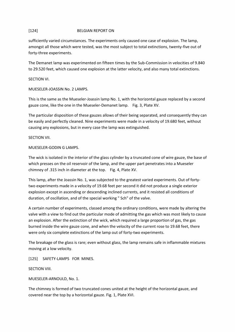
[124] BELGIAN REPORT ON
sufficiently varied circumstances. The experiments only caused one case of explosion. The lamp,
amongst all those which were tested, was the most subject to total extinctions, twenty-five out of
forty-three experiments.
The Demanet lamp was experimented on fifteen times by the Sub-Commission in velocities of 9.840
to 29.520 feet, which caused one explosion at the latter velocity, and also many total extinctions.
SECTION VI.
MUESELER-JOASSIN No. 2 LAMPS.
This is the same as the Mueseler-Joassin lamp No. 1, with the horizontal gauze replaced by a second
gauze cone, like the one in the Mueseler-Demanet lamp. Fig. 3, Plate XV.
The particular disposition of these gauzes allows of their being separated, and consequently they can
be easily and perfectly cleaned. Nine experiments were made in a velocity of 19.680 feet, without
causing any explosions, but in every case the lamp was extinguished.
SECTION VII.
MUESELER-GODIN G LAMPS.
The wick is isolated in the interior of the glass cylinder by a truncated cone of wire gauze, the base of
which presses on the oil reservoir of the lamp, and the upper part penetrates into a Mueseler
chimney of .315 inch in diameter at the top. Fig. 4, Plate XV.
This lamp, after the Joassin No. 1, was subjected to the greatest varied experiments. Out of forty-
two experiments made in a velocity of 19.68 feet per second it did not produce a single exterior
explosion except in ascending or descending inclined currents, and it resisted all conditions of
duration, of oscillation, and of the special working " Sch" of the valve.
A certain number of experiments, classed among the ordinary conditions, were made by altering the
valve with a view to find out the particular mode of admitting the gas which was most likely to cause
an explosion. After the extinction of the wick, which required a large proportion of gas, the gas
burned inside the wire gauze cone, and when the velocity of the current rose to 19.68 feet, there
were only six complete extinctions of the lamp out of forty-two experiments.
The breakage of the glass is rare; even without glass, the lamp remains safe in inflammable mixtures
moving at a low velocity.
[125] SAFETY-LAMPS FOR MINES.
SECTION VIII.
MUESELER-ARNOULD, No. 1.
The chimney is formed of two truncated cones united at the height of the horizontal gauze, and
covered near the top by a horizontal gauze. Fig. 1, Plate XVI.
This lamp was often put out at once in strong and plunging currents. One variation gave a bad light
on this account, and also because of the fineness of the top gauze (1,161 meshes to the square
inch); and this was the same with another sample when the glass cylinder was accidentally too thick,
and curtailed too much the passage of the air between the glass cylinder and the bell-widening of
the base of the chimney.
Moreover, the combustion of the gas being thrown back by the bell-widening against the glass,
caused its fracture to become relatively much more frequent.
Another sample, however, did not present these defects.
The Mueseler-Arnould lamp was submitted to many experiments in explosive currents moving at a
velocity of 19.680 feet. Here again some experiments, classed amongst the ordinary ones, were
made whilst trying to work the valve in order to produce an explosion.
Out of thirty-six experiments it only caused one explosion and two cases of combustion in the
interior of the chimney.
SECTION IX.
MUESELER-ARNOULD No. 2 LAMP.
In this lamp the chimney is of the same general shape as the preceding one, with the addition of a
small Mueseler chimney inside. Fig. 2, Plate XVI.
The lamp burned properly, and was less easily extinguished than the preceding one in plunging
currents. Out of ten experiments it caused two cases of explosion.
SECTION X.
MUESELER-GODIN C LAMPS.
Here the wick is separated from the interior of the glass by a crystal prolongation of the chimney,
resting on a copper gallery perforated with small holes. The chimney is of the ordinary Mueseler
types, .334 inch diameter at the top and slightly shortened at the base. Fig. 3, Plate XVI.
This lamp is one of the varieties of lamps with isolated flame presented by M. Godin, which gave
relatively good results in the experiments made by the Sub-Commission. When the samples with a
chimney half
[126] BELGIAN REPORT ON
crystal and half tin only are considered, the thirty-eight experiments to which these lamps were
submitted occasioned only one case of explosion; but the isolation not being perfect, the gas was
several times seen to burn between the two glasses under the horizontal gauze, and the method of
isolation by a horizontal wire gauze or with perforated copper, both of which being apt to become
dirty, would lead to the supposition that in practice the light would be bad.
The isolation of the wick in the Arnould Nos. 1, 2, 3 lamps, tried by the Commission, seems to be
carried out in a more rational manner.
As to total extinctions, they were rarely produced when the velocity of the mixture reached 19.68
feet.
SECTION XI.
MUESELER-GODIN D LAMPS.
The same lamp as the preceding one, excepting that the copper gallery is replaced by small studs to
support the interior glass, which consequently ceases to completely isolate the wick. Fig. 4, Plate
XVI.
This lamp is of a more practical construction than the preceding one. However, out of thirty-two
experiments under the conditions stated above, of which seventeen were at a velocity of 19.68 feet,
it occasioned three cases of explosion. It was also submitted by the Sub-Commission to thirteen
experiments made with a velocity of 11.480 to 14.760 feet, and occasioned three explosions.
SECTION XII.
MUESELER-GODIN H LAMPS.
Sample with cylinder entirely of gauze, and sample with cylinder half gauze and half tin, both
furnished with a Mueseler chimney with a second horizontal gauze. Fig. 1, Plate XVII.
Out of seven experiments in a velocity of 19.680 feet, this lamp occasioned one explosion, and not
one case of simple extinction.
During the experiments by the Sub-Commission with samples of this lamp, in velocities of from 9.840
to 29.52 feet, two cases of explosion and six cases of simple combustion of gas in the cylinder were
occasioned.
Sample with the cylinder half gauze and half tin. This lamp burned very badly and gave very little
light, which caused the Commission to abandon their experiments with it.
SECTION XIII.
MUESELER-HARMEGNIES No. 5 LAMP.
A Mueseler chimney furnished in the interior of the glass with an inverted truncated cone of tin,
joining the lower side of the chimney to
[127] SAFETY-LAMPS FOR MINES.
the side of the horizontal gauze (almost in the same way as the truncated cone of wire gauze of the
Mueseler-Demanet lamp). This truncated cone partitions off a certain cavity A under the horizontal
gauze, from whence a large tube descends almost to the level of the wick to feed the flame. Fig. 2,
Plate XVII.

The construction of this lamp prevented the Commision seeing what occurred after the extinction of
the wick, and, after making three trials, resulting in one explosion, they did not think that it was
necessary to continue the experiments.
The Sub-Commission obtained one explosion out of seventeen experiments.
SECTION XIV.
MUESELER-HARMEGNIES No. 6 LAMP.
The lower cone of No. 5 is suppressed and the horizontal gauze is replaced by a disc of tin from
whence the tube A starts to feed the wick. A wire gauze cone similar to that of the Mueseler-Joassin
is laid on the edge of this disc and fastened to the chimney near the top. Fig. 3, Plate XVII.
The Commission obtained two explosions from two trials in a velocity of 19.680 feet and did not
continue the experiments.
SECTION XV.
MORISON LAMP (TWO SAMPLES SLIGHTLY DIFFERENT).
In this class of lamp there are two glasses as in the old Rocour lamp, and the wick is isolated by an
interior glass. It has the sheet iron chimney of the old Elvin lamp, surmounting the interior glass; this
chimney is formed of two truncated cones united at their smallest bases at a distance of, in one case
2.362 inches, and in another 1.259 inches, above the horizontal gauze. The fittings are joined by
screws and nuts. Fig. 4, Plate XVII.
These lamps are of a very complicated construction, give a very bad light in stagnant air, and were
extinguished in the testing apparatus by the plunging current of air coming from the trap door. Out
of eleven experiments at a velocity of 19.68 feet, these lamps caused neither exterior explosions nor
any inflammation of gas in the exterior cylinder. There were five complete extinctions; but some of
them only might have been apparent because it was impossible to see under the lower gauze.
The combustion of the gas filled the whole of the internal glass at times; it was often confined to the
base and there were probably cases where it burnt without passing the lower gauze. Several parts of
the lamp were unsoldered by the heat.
[128] BELGIAN REPORT ON
The Sub-Commission submitted these lamps to nineteen experiments in explosive currents moving
at a velocity of from 13.129 to 29.520 feet per second, with the same results, but it was also
remarked that the ignited gas passed the bottom gauze, entered between the two glasses, and burnt
under the upper horizontal gauze.
SECTION XVI.
MORISON-ARNOULD LAMP (TWO SAMPLES SLIGHTLY DIFFERENT).
Morison lamp modified, made more in the form of the ordinary Mueseler lamp, and of a
construction more practical than the preceding one, but they still burn with difficulty, and are easily

extinguished, particularly one sample where the interior gauze near the top part of the chimney had
a very close mesh. Fig. 1, Plate XVIII.
Out of eight experiments these lamps did not cause any case of explosion or of passage of flame into
the cylinder. There was not a case of total extinction, and the flame in one of the experiments made
with the other sample appeared to have passed between the two glasses.
SECTION XVII.
LAMPS WITH CHIMNEYS AND NUMEROUS TUBES.
In these the chimneys were furnished with the two cones of wire gauze of the primitive Mueseler-
Joassin No. 2 lamp ; they are in two pieces to permit the cleaning of the two cones. Figs. 2 and 3,
Plate XVIII.
The tubes are in clusters tangential to one another and leave between them other little passages.
These clusters can easily be taken off for cleaning.
MUESELER-JOASSIN No. 2 LAMP WITH TUBULAR CHIMNEY.
One specimen had in the interior of the chimney and at 1.023 inch from its extremity, a cluster of
three small tubes of 1.063 inches in height, and of .196 inch minimum diameter. (Fig. 2, Plate
XVIII.)
Another specimen had in the interior of the chimney and at .708 inch extremity a cluster of small
tubes of .984 inch in height and of .167 inch minimum diameter.
Another specimen had in the interior of the chimney at .708 inch from the top a cluster of small
tubes of .866 inch in height and .130 inch minimum diameter.
In another specimen the top part of the chimney has a square section containing four long
immovable tubes of 1.889 inch in height and of .187 inch minimum diameter. The chimney might
have been divided into small passages according to the axis. Fig. 3, Plate XVIII.
[129] SAFETY-LAMPS FOR MINES.
MUESELER-DEMANET WITH CHIMNEY AND NUMEROUS TUBES.
Chimney in one piece, provided with the two gauzes of the primitive Mueseler- Demanet lamp and
terminated at its extremity by a copper cylinder of .787 inch in height, perforated with six slightly
conical holes of .157 inch minimum diameter. Fig. 4, Plate XVIII.
These lamps all behaved nearly in the same manner. They light properly ; but they seem to be easily
extinguished in ascending currents. There has only been one case of simple total extinction ; but the
tests have not been prolonged after the slide door was brought to and maintained at a fixed point.
Putting aside five experiments made in horizontal currents and in conditions resulting from the
special manoeuvre " Sch" of the valve, experiments, which, concurrently with those principally
undertaken on the primitive Mueseler-Joassin lamp, show the extreme difficulty that there would be
in producing explosions in such currents with lighting apparatus provided with multitubular

chimneys such as the above, all the experiments have been in ascending currents which had
previously been found eminently dangerous.
In ascending currents every one of the multitubular lamps contributed one case of explosion in a
velocity of 19.680 feet, but it was noticed that each time an explosion took place the position of the
lamp experimented on was such that before the arrival of the gas the flame of the wick was found to
vacillate strongly or to be crushed down on the wick, which indicated the presence of whirling
currents or eddies in the moving mixture whereby a sudden ascending inflection was produced in
the currents just as it began to impinge on the lamp. Thus the frequency of the explosions was much
oftener caused by these whirlings or eddies than by the simple velocity of the current, and the whole
of the experiments made by the Commission prove that only those circumstances may be
considered as dangerous which reverse the currents of air and cause them to flow in a different
manner to that which the lamp was designed to produce, and this reversal of the current is made
manifest by the agitation and beating down of the flame.
Lighting of Fiery Mines.—Royal Decree of the 17th June, 1876.
REPORT TO THE KING.
Sire,—For more than half a century laudable efforts have been made, as well in Belgium as in other
countries, to find a mode of lighting fiery mines without danger.
[130] BELGIAN REPORT ON
These efforts have not been without results.
A first and remarkable result was obtained in 1815 by the invention of the Davy lamp.
Received at first with distrust, the Davy lamp however did not fail to make rapid progress, and for a
certain time it was considered an infallible preventative against an explosion of fire-damp. Later
experience proved that its merit had been a little exaggerated, and that it possessed certain
imperfections. Numerous endeavours had been made to obviate these, when in 1840 a Belgian
mining engineer, the late M. Mueseler, offered a safety-lamp of his invention to a Commission
charged by the Department of Public Works to make comparative trials of the principal apparatus in
use for lighting mines.
This Commission came to the conclusion that the Mueseler lamp combined, in a greater degree than
all those submitted to their examination, the essential conditions of a good safety-lamp. However,
they thought it well to await the results of its practical use before definitely deciding the question.
During the first few years the new apparatus was but partially used, and the Government thought it
their duty to encourage the inventor by granting him a subsidy which enabled him to reduce the
price.
In 1851 the Mueseler lamp was allowed, along with others, to be used in lighting fiery mines until
actual practice would permit of a judgment being formed on the relative merits of each system.

At length, in 1864, it was acknowledged that the Mueseler lamp was the one whose employment
presented the greatest security for the miners, and by a Ministerial Order of the 29 th of April, of the
same year, the use of it was declared obligatory in fiery mines.
But the Department of Public Works having been petitioned since that time to decide upon the
employment of new safety-lamps, of which several used mineral oil (petroleum), instituted, by an
order dated the 20th of January, 1808, a Commission charged to proceed with a comparative
examination of these lamps and of those of which the use was already authorized.
This Commission, after numerous and lengthened experiments (see the account of these
experiments, Vol. 31, pages 306 to 517, of the " Annales Travaux Publics"), reported that the
Mueseler lamp, fed with vegetable oil, is in every respect superior to all the others submitted to its
examination.
In consequence, it concluded that this lamp should be the only one admitted for the lighting of fiery
mines, except the Mueseler- Godin, the large Mueseler, and the Deputy's or testing lamp.
[131] SAFETY-LAMPS FOR MINES.
As to mineral oils, the Commission thought that by their nature, and the great variation in their
composition, they were too dangerous for their use to be authorized in fiery mines.
I can only endorse these conclusions, which appear to me plainly justified, and I think it my duty in
consequence to propose to your Majesty to approve of them.
The orders concerning the lighting of fiery mines being at present contained in several general and
provincial regulations, I think that it would be useful to unite them in one decree only, in order to
make the Whole of them better appreciated, and thus facilitate their application.
The annexed decree having been conceived in accordance with the preceding remarks, I hope that
your Majesty will deign to favour it with your sanction.
The Minister of Public Works,
A. Beernaert.
Leopold II., King of the Belgians.
TO ALL PRESENT AND TO COME, GREETING.
With regard to the Royal Decree of the 11th of August, 1841, and 29th of June, 1844, and 7th of July,
1847, approving the laws concerning the lighting of fiery mines in the provinces of Hainaut and
Liege;
With regard to the Articles 11 to 15 of the Royal Decree of the 1st of March, 1850, relative to the
lighting of the fiery mines of the kingdom;

With regard to the Ministerial Orders of the 29th April, 1864, declaring that the Muesler type of
lamp is obligatory for the lighting of the said mines;
With regard to the report of the Special Commission, instituted by the order of our Minister of Public
Works, dated 20th of January, 1868, for a comparative examination of safety-lamps fed by mineral
and vegetable oil;
Considering that it results from this report, and the experiments to which the different lamps have
been submitted, that the Mueseler lamp is, amongst all others, the one which presents in actual use
the greatest security for the miners;
Considering that it is important to the safety of the working miner, and for the protection of the
works, to put a stop to the employment of Mueseler lamps modified in form so as to diminish their
efficacy;
Considering that for the same motives it is desirable to prevent the the employment of explosive oils
in the interior of fiery mines;
[132] BELGIAN DECREE ON
Wishing to reunite in a single decree the different statutes and regulations relating to the lighting of
fiery mines;
With regard to the laws of the 21st April, 1810, and the decree of the 3rd January, 1813, upon
mines;
With regard to Article 67 of the Constitution;
On the proposition of our Minister of Public Works,
We have decreed and do decree :
Article 1.—That no other than the Mueseler type of lamp, fed with vegetable oil, conforming to Fig.
1, Plate XIX., joined to the instructions annexed to the present decree, be permitted to be used in
lighting fiery mines. In order to facilitate the employment of this lamp, it may be varied according
to the modifications indicated in the instructions by the letters A, B, C, D, E, F. Fig. 2, Plate XIX.
Article 2.—No other apparatus or mode of lighting will be allowed without a prior authorization of
our Minister of Public Works, except as follows:—
A.—The agents appointed for the inspection of the works, and who are not employed as workmen,
can make use of the Mueseler-Godin lamp, with interior glass, simply supported without a
protecting gauze or bottom support. Fig. 3, Plate XIX.
B.—For the fixed lighting of shafts and some hanging-on places, ventilated by pure air coming direct
from the surface, the mining engineers can permit the use of lamps of the Mueseler design of a
larger size than the type, fed by vegetable oil. Plate XX.
C—The chief mining engineers can, in any particular case, permit provisionally mining engineers,
overmen, back overmen, and deputies, the use of the lamp called the Deputy's or testing lamp when

made of the prescribed dimensions, with a double gauze of at least 1,451 meshes to the square
centimetre, the metallic thread having a diameter of .01 inch. (No. 20 wire gauge of Liege, or No.
30 English gauge).
Article 3.—The safety-lamps must be made to lock, and when not in use remain deposited in the
lamp house. Special agents must take care to see that each lamp is of the type admitted or
tolerated by the Administration of Mines; they are besides charged to examine them and cause
them to be cleaned each day and maintained in good condition by experienced workmen.
[133] SAFETY-LAMPS FOR MINES.
Article 4.—At the time of descending, a lamp is to be given to each workman, who must assure
himself that it is locked.
Article 5.—The lamps which go out in the mine must be sent either to the surface, or to some place
in the mine, where they are to be examined, re-lit, and re-locked by men expressly charged with this
duty, and under the supervision and direction of the overmen and deputies. The stations where the
lamps are to be re-lit are, at the instance of the inspecting engineers, fixed by colliery engineers
entered in the standing orders of the mines, in conformity with Article 31 of the Act of March 1st,
1850.
Article 6.—It is strictly forbidden to open lamps in any part of the mine excepting in the places
appointed by the management.
Article 7.—Every workman who carries an unlocked lamp, or any instrument by means of which his
lamp can be opened, is to be immediately taken in charge either by duly-sworn special watchmen, or
by the officers of the mine, or by the local police, and the particulars of the offence committed to
writing.
Article 8.—It is forbidden to smoke in the mine. Every miner who carries a pipe, steel, or match, or
any other article with the object of obtaining a light, is to be dealt with in accordance with article 7.
Article 9.—The term fiery mine is applicable to those places which come under Article 31 of the Act
of March 1, 1850.
Article 10.—When fire-damp appears in a drift or level in sufficient quantity to cause a continuous
lengthening of the flame in the lamps, work must be immediately suspended until the danger has
passed away.
Article 11.—All objections which may be urged against the carrying out of these laws, as well as
petitions for delay in putting them into execution, must be addressed to the permanent deputation
of the Provincial Council, who will decide upon them after having taken the opinion of the chief
mining inspector. Appeals against the decisions of this tribunal, whether they are on behalf of the
Government engineers, or on behalf of the proprietors of mines, must be addressed to our Minister
of Public Works.
Article 12.—A pattern lamp of each of the systems permitted or tolerated is to be deposited at the
Department of Public Works as well as in each sectional bureau and mining district. In all that

concerns the dimensions and forms of the essential parts of the lamps, the instructions annexed to
the present decree must be strictly conformed to.
[134] BELGIAN DECREE ON
A sufficient number of gauges to ascertain the number of meshes and the size of the wires in the
metallic gauzes will be placed at the disposal of the mine officials.
Article 13.—Infractions against the provisions of the present decree are verified, prosecuted, and
judged conformably to Code X. of the law of the 21st April, 1810, relating to mines, minerals, and
quarries.
Article 14.—The present regulations must be affixed by the directors or proprietors of fiery collieries
in a place accessible to the workmen.
Article 15.—The orders relative to the lighting of mines contained in the Royal decrees aforesaid, of
the 11th August, 1841, 29th June, 1844, and 7th July, 1847, and in the Ministerial Order of the 29th
April, 1864, are repealed.
Our Minister of Public Works is charged with the carrying out of the present decree, which will be
inserted in the
"Moniteur," as well as the instructions above mentioned.
Given at Brussels the 17th June, 1876.
Leopold.
By the King:
The Minister of Public Works,
A. Beernaert.
Lighting of Fiery Miner.—Instructions Annexed to the Royal Decree, June 17th, 1876.
I.—Mueseler pattern lamp, Fig. 1, Plate XIX., dimensions and forms of the essential parts. Drawing
No. 1, A.—Glass cylinder, furnished at its ends with metallic ring sockets, the upper socket covering
the edge of the horizontal gauze:—
Exterior diameter ... ... ... ... ... ... 2.364 inches.
Thickness ... ... ... ... ... ... ... .216 ,,
Height, including lower socket not more than ... ... 2.442 „
B.—Inside chimney of thin iron. Conical tube widened into a bell-shape at the base :—

Interior diameter at the top not more than ... ... .394 inches.
Do. at the base not more than ... ... 1.182 „
Do. at the commencement of the widening
not more than... ... ... ... ... ... .985 „
Height of that part of the chimney above the horizontal gauze ... 3.546 „
[135] SAFETY-LAMPS FOR MINES.
Height of the part of the chimney under the horizontal
gauze, comprising the bell-widening at the base ... 1.063 inches.
Height of the bell-widening at the base ... ... ... .236 „
Distance from the base of the chimney to the top of the
wick tube ... ... ... ... ... ... .866 „
C.—Cap of wire gauze; a closed envelope of cylindrical form surmounting the glass:—
Height ..................... 4.294 inches.
D.—Wire gauzes (of the cap and the horizontal gauze) made with wires of at least .013 of an inch in
diameter, with a minimum of 928 meshes to the square inch.
With the view of lessening the difficulties which would present themselves in practice by the
rigorous observance of the dimensions ordered in the foregoing, the following margin is allowed :—
A.—For the exterior diameter of the glass .039 of an inch more or less.
B.—For the thickness of the sides of the glass .019 inch more or less.
C.—For the length of each of the parts of the chimney taken from the horizontal gauze as
well as for the distance which separates the base of the chimney from the top of the wick carrier,
.078 inches more or less. The chimney is only limited in height from the horizontal gauze in order to
facilitate the examination of the roof of the workings for firedamp.
D.—Suppression of the bell-shaped widening at the base of the chimney, which must not in this
case exceed 1.024 inches in the lower diameter.
E.—For the height of the gauze cap .157 inch more or less.
F.—Reduction of the diameter of the wire of the gauze even to .009 of an inch when the number of
meshes attain or exceed 1,451 to the square inch.
II.—Drawing No. 3.—Mueseler-Godin lamp, for overmen charged with the superintendence of the
works, and who are not employed as workmen. Fig. 3, Plate XIX.
III.—Drawing No. 4.—Mueseler lamp, large size, for the fixed lighting of shafts, etc. Plate XX.
A.—Cylindrical glass.
Exterior diameter ... ... ... ... 2.364 to 2.758 inches.
Thickness ............... .216 to .315 „
Height not more than .,. .,. ... ... 3.937 „
[136] BELGIAN DECREE ON
B.—Conical chimney :—
Diameter at the top, maximum ... ... ... .591 inches.
Do. at the base do. ......... 1.379 „
Height of the part above the horizontal gauze at least 3.546 inches, when the mean of the diameters
at the top and at the base does not exceed .788 inches, and .393 inches of increase of height for
each .039 inches in . diameter, which shall be in excess of this mean.
It follows, therefore, that for the maximum diameter of .591 inches at the top, and of 1.379 inches at
the base, the height of the part of the chimney above the horizontal gauze should be at least 5.516
inches
[mathematical expression]
Height of the part below the horizontal gauze, to be at least equal to half the distance of the said
gauze from the top of the wick carrier.
In taking the case of a lamp furnished with a glass of 3.940 inches in height, and provided with a wick
tube elevated .945 inch above the lower edge of this glass, the distance from the base of the
chimney to the horizontal gauze ought to be at least half of 2.995 inches, or 1.497
inches.
C.—Wire gauzes.
The same gauzes as for lamps of ordinary make.
In order to prevent the horizontal gauze of the cap becoming quickly impaired by the heated air
from the chimney, the latter can be furnished with a thin iron apparatus (see the plate) designed to
break the current of warm air a little beneath the said gauze.
The drawing No. 4 before mentioned represents a lamp of the maximum form, in accordance with
the dimensions given above.
The lamp may be advantageously provided with a reflector and a feeding reservoir at a constant
level.
IV.—Construction and maintenance of lamps.
Lamps should be constructed and maintained with care. Their different parts should be well
fastened into the framework; the cap or outside covering of wire gauze should fit exactly to the
glass, which should fit perfectly on the reservoir.
The custom adopted in many mines of numbering the lamps, and assigning every day to the same
workman the same lamp, not only assures their good preservation, but realizes an excellent check
on the numbers of the people in the works. It is important also for the maintenance of the lamps in
good condition that they be kept in repair by a well-qualified lamp inspector employed at the
colliery, and not given to a lamp contractor to keep in order.
[137] SAFETY-LAMPS FOR MINES.
The drawing No. 1 gives the proportions of the pieces generally adopted in the basin of Liege; the
drawing No. 2 those more particularly in use in the basin of Hainaut.
Besides the instructions before mentioned, the following recommendations may be made :—
A.—The reduction of the diameter of the chimney at the top. This reduction augments the safety of
the lamp especially in inflammable currents travelling at a high velocity.
B.—The employment of the cone of wire gauze touching the chimney a certain height above the
horizontal gauze, and being fitted on its lower edge to the circumference of the gauze (Joassin
arrangement). Figs. 1 and 2, Plate XXI. C.*—The isolation of the wick to the interior of the lamp by
the Godin cone of wire gauze, springing from between the glass and the lower socket, and entering,
a tight fit, within the thin sheet iron chimney. Fig. 3, Plate XXI. The sample of the Mueseler-Joassin
lamp, which, during the numerous experiments made by the Commission, presented such a superior
degree of security, had .334 inch diameter at the top.
D.—The isolation of the wick by an interior glass, whose lower edge fits into a space separated by
wire gauze, and the upper part of which fits by friction inside the thin iron chimney cut off at its base
(combined design of Arnould and Godin). Fig. 4, Plate XXI
The examples of lamps with the flame isolated to the interior of the glass, which, submitted to the
experiments, have given results relatively favourable, had .334 and .354 inch diameter at the top.
V.—Rapid currents of air. These currents are particularly dangerous when their action manifests
itself by the crushing of the flame upon the wick. Indeed, the relative security of the Mueseler lamp
does not depend alone on the smallness of the section of the chimney, especially at the top, or on its
height, but rests essentially in the regularity of the draught. It is also to be remarked that when by
any cause whatever the supply of air happens to reverse in the interior of the lamp, a circumstance
which shows itself by the crushing of the flame under the chimney, the inflammation of the gas
extends itself with the greatest facility into the upper cap.
* The examples C and D are recommended for lighting certain dangerous workings, and especially
where there is any danger of the breakage of the glass.
B and C are council orders, notably for the lighting of workings with a sharp ventilating current and
much dust.

[138] BELGIAN DECREE.
The responsible agents of the collieries ought to watch that the workmen handle the lamps with
prudence, and that they do not expose them either to concussion or irregular motions. They should
be held as much as possible sheltered from rapid currents, particularly currents producing a strong
vacillation of the flame.
Apart from the explosions which occurred during the experiments made by the commission in an
inflammable mixture moving at a high velocity, it suffices here to record that when this speed
equalled 9.840 feet per second the gas almost always continued to burn under the horizontal gauze.
VI.—The Commission insists on this important point, that the Mueseler lamp, in every way superior
to the Davy and other apparatus of the same kind, presents, nevertheless, like all other so-called
safety lamps, only a relative security. It is then, in fact, only an auxiliary apparatus, necessary in fire-
damp mines to complete a state of security which should depend principally on active ventilation
and a good laying out of the workings.
It is to be observed, further, that variations in the temperature of the air at the surface and in the
atmospheric pressure can exercise a disastrous influence on this security. It is expedient that each
mining centre should be provided with the proper instruments to ascertain the state and
temperature of the atmosphere. The officers of the mines will indicate the position where the
barometer and thermometers must be placed, and the nature of the observations to be taken every
day.
Approved to be annexed to our Decree of the 17th June, 1876.
Leopold.
By the King :
The Minister of Public Works,
A. Beernaert.
[000 between pages 138 and 139
Plate XIV, To illustrate the Report of the Belgian Commission on Safety Lamps.- Fig.1, Davy; Fig. 2,
Deputy's Lamp; Fig. 3, Irvin; Fig. 4, Mueseler; Fig. 5, Mueseler-Thonard.
Plate XV, To illustrate the Report of the Belgian Commission on Safety Lamps.- Fig. 1, Mueseler-
Joassin No. 1; Fig. 2, Mueseler-Demanet; Fig. 3, Mueseler-Joassin No. 2; Fig. 4, Mueseler-Godin G.
Plate XVI, To illustrate the Report of the Belgian Commission on Safety Lamps.- Fig. 1, Mueseler-
Arnould No. 1; Fig. 2, Mueseler-Arnould No. 2; Fig. 3, Mueseler-Godin C; Fig. 4, Mueseler-Godin D.
Plate XVII, To illustrate the Report of the Belgian Commission on Safety Lamps.- Fig. 1,Mueseler-
Godin H; Fig. 2, Mueseler-Harmegnies No. 5; Fig. 3, Mueseler-Harmegnies No. 6; Fig. 4, Morison
Plate XVIII, To illustrate the Report of the Belgian Commission on Safety Lamps.- Fig. 1, Morison-
Arnould; Fig. 2, Mueseler-Joassin No. 2 with tubular chimney; Fig. 4, Mueseler-Demanet.

Plate XIX, To illustrate the Royal Decree on the lighting of mines in Belgium.- Fig. 1, Mueseler type;
Fig. 2, Variety of Mueseler used in the Hainaut coal field; Fig. 3 Mueseler-Godin for Deputies.
Plate XX, To illustrate the Royal Decree on the lighting of mines in Belgium. Mueseler-Grand-Format.
Plate XXI, To illustrate the Royal Decree on the lighting of mines in Belgium. Fig. 1, Variety of
Mueseler-Joassin Lamp; Fig. 2, 2nd variety of Mueseler-Joassin; Fig. 3, 2nd variety of Mueseler-Godin
lamp; Fig. 4, Mueseler-Arnould-Godin lamp.]
[139]
Table showing the dimensions and description of the most important parts in the lamps authorised
by the Royal Decree of June 17th, 1876.
[table]
[140] PROCEEDINGS.
In the absence of Mr. Sawyer, the Secretary then read that gentleman's paper—"Notes on the
Mueseler Lamp."
[141] Notes on the mueseler lamp.
NOTES ON THE MUESELER LAMP.
By A. R. SAWYER.
Having had daily practical experience with the Mueseler lamp in the collieries in his district, the
writer thought that a few remarks on its efficiency under ordinary circumstances would be useful to
the members of this Institute.
This lamp was invented by a Belgian mining engineer, the late Mr. Mueseler, in 1840. It was
examined by several Royal Commissions, which, after careful and prolonged trials, found and
declared it to be in all respects superior to every other, and to present the greatest amount of
security.
Thereupon an Act was passed in 1876 making the use of the Mueseler lamp compulsory throughout
all coal mines.
The seams of North Staffordshire vary much in their inclination in different localities. The dip of the
seams varies from the vertical to the horizontal. Many are very fiery. The " gas" which they produce
is of very varying composition, judging from the odour and behaviour in the lamp. The presence of
defiant gas, a constituent of fire damp, is disputed by many, but the writer believes it to form more
or less a part of the constitution of fire-damp in North Staffordshire.
Olefiant gas or ethylene [chemical formula] differs from marsh gas in being a hydro-bicarbonate. Its
specific gravity is .9688; it is transparent and colourless, has a faint, sweetish, alliaceous odour, is
very inflammable, and burns with a white luminous flame. It is inflammable at a mild red heat, and
causes a much more powerful explosion than marsh gas.
Bishof found 16 per cent, of olefiant gas in fire damp of the lias formation, 6 per cent, in that of a "
blower" at Wellesweiler, and 2 per cent, at Gerhard Colliery. He, therefore, defined fire damp as a
mixture of marsh gas [chemical formula], olefiant gas [chemical formula], hydrogen, and carbonic
anhydride [chemical formula].
The fire damp in some of the seams invariably possesses the odour of olefiant gas. When elevated
towards it the Mueseler lamp shows a
[142] NOTES ON THE MUESELER LAMP.
" cap," and then immediately goes out with a sharp noise, before the Davy shows any sign of gas. On
a closer approach with the Davy the gas fires in it, and burns with a whitish flame. When this odour
was less strong the writer has been able to fire the gas in the Mueseler lamp without its going out,
by elevating it with care. In gas in which this odour is not perceptible, the Mueseler lamp on being
elevated is first surmounted by a distinctly-shaped cylindrical blue flame, which loses itself in the
chimney and then goes out. If carefully lowered, however, it will retain its flame.
The Mueseler is the most delicate lamp for detecting gas in the air currents. It shows a blue aureola
or " cap" in places where the Davy shows none, thereby discovering a smaller percentage of gas than
the latter. This is no doubt due to the steadiness of the flame produced by the regularity of the
draught, but also to the flat wick, which is easily movable by means of a broad pricker. A good deal
also depends on the quality of the oil, as with pure vegetable oil the flame can be lowered so as to
remove the luminous envelope and leave the pale blue portion of the flame only. Mineral oils should
never be taken underground; in Belgium it was found that they lessened the safety of the lamp, and
are prohibited. The writer has detected small quantities of gas in pot holes into which the Mueseler
could only just be introduced, and where the Davy did not disclose any. The pot hole being high, the
Davy could not be tilted for the purpose of bringing the flame to the gas; but in the Mueseler, owing
to the current which is set up, the gas was brought to the flame.
Of all the lamps known the Mueseler is the one that gives the best light. The steadinesss of the flame
remains unaltered by the velocity of the air in returns, where it can be lowered to a pale blue flame,
when a Davy would be put out.
The sensitiveness of this lamp is often exaggerated. It requires a little more care in handling than a
Davy, an obligation which is highly beneficial, for if tilted to one side it goes out, owing to the
products of combustion mixing with the air, and thereby saves the glass.
The fact that the flame of an explosion travels towards the incoming air rather than along the return
is well exemplified in the Mueseler lamp. If the outer gauze is removed, and the lamp placed in an
explosive mixture, the explosion will not be communicated through the chimney; it will be checked
by the horizontal gauze and go out. The writer found this out unexpectedly one day; having
forgotten the outer gauze, he placed the lamp in gas, with the above result. The reason the flame
travels apparently in the direction of greatest resistance is that it seeks
[143] NOTES ON THE MUESELER LAMP.

the air necessary for its existence. He has also seen the outer gauze removed, and the lamp exposed
to a current of gas travelling 11 feet per second, without communicating the flame. The gas went on
burning below the horizontal gauze for four minutes when the experiment was stopped. This shows
that in ordinary cases, even if the outer gauze is injured, the lamp is still safe.
Complete extinction of the flame and gas takes place in currents not surpassing a velocity of 9.84
feet. If the velocity of the current increases, the flame goes out, but the gas goes on burning
underneath the horizontal gauze for some time. Ignition of the gas within the outer gauze takes
place if the draught by some reason or another is reversed just before its arrival. The writer never
yet saw the gas fire within the outer gauze in the pit. The typical Mueseler lamp which he uses was
made by Messrs. Mulkay Brothers, Outre-Meuse-Liege. It weighs 2 1/4 lbs., cost 4s. 0d., and gives
the greatest satisfaction.
For the work of inspection a simple Davy should be used as well as the Mueseler, as for that purpose
both have their uses. If firemen are equally provided, knowing the properties of each and using them
accordingly, they may be considered safely and efficiently provided for their work. Several collieries
in the district have adopted this plan, and the firemen all speak in favour of it.
In seams in which "blowers" are likely to be met with, or which are fiery, simple Davy lamps at the
face are very questionable. The recent explosion at Leycett, which was due to the gas lighting at the
only Davy lamp at the face, has shown this more strongly. All the other lamps were Teale's, an
imitation of the Mueseler, which resembles it in going out in gas.
The following modifications of the Mueseler lamp, though not classed amongst those authorized in
the Act, are, nevertheless, highly approved of. These are :—
1.—The Mueseler-Joassin lamp, in which the chimney is supported, as shown in Figs. 1 and 2, Plate
XXI. It is particularly applicable in strong currents, where much dust prevails. The top end of the
chimney should be .334 inches in diameter.
2.—Another variety of the Mueseler-Godin lamp, Fig. 3, Plate XXI., having an internal gauze between
the flame and the glass. This lamp and the next are highly to be recommended where there is a
possibility of the glass getting broken, as they are doubly safe.
[144] NOTES ON THE MUESELER LAMP.
3.—The Mueseler-Arnould-Godin lamp, which differs from the Mueseler-Godin, Fig. 4, Plate
XXI., in having the support of the internal glass cylinder surrounded with gauze. The top end of
chimney should be from .334 to .354 inches in diameter. In conclusion, it is advisable to lay great
stress on the fact that the Mueseler, as well as all so-called safety lamps at present known, only offer
a relative amount of security. They are, therefore, only auxiliaries necessary to complete a state of
security mainly dependent on powerful ventilation and good disposition of workings.
Mr. Ashworth said, in reference to Mr. Sawyer's suggestion that a fireman should carry both a
Mueseler and a Davy lamp, that one of the principal objects he had had in view in contriving his
modification of the Davy was to place in the hands of a miner a lamp which would combine the
advantages of the Davy with those of the Mueseler.

Mr. T. Lindsay Galloway had much pleasure in proposing a vote of thanks to Mr. Sawyer. He thought
that the fact of that gentleman having himself used the Mueseler lamp underground for a
considerable time gave an additional value to his paper, as there were other points besides the
velocity-test which could be best ascertained by personal observation in the mine.
Mr. Cooke seconded the vote of thanks, which was unanimously carried.
Mr. James Ashworth then read a paper on " Improved Safety-Lamps of the Davy and Mueseler
types" :—
[145] IMPROVED SAFETY-LAMPS.
IMPROVED SAFETY-LAMPS OF THE DAVY AND MUESELER
TYPES.
By JAMES ASHWORTH.
The importance of having a good and reliable safety-lamp, combined with a simple yet secure lock,
has been for many years patent to all members of the mining community who have studied the
subject; and it is not a little curious to note that until a few years ago persons having no practical
knowledge of the working or requirements of a coal mine were those who pointed out the insecurity
of the Davy and other safety-lamps, and who endeavoured to produce more reliable lamps; but now,
thanks to the information disseminated by Mining Institutes, and this Institute in particular, many
alterations have been made by their members to improve the construction of what may be termed
our three standard lamps, viz. the Davy, the Stephenson, and the Clanny.
The lamps that have received the writer's greatest attention are the Davy and the Mueseler, and it is
proposed to give a description of some suggested improvements in the construction of these lamps
and the tests to which they have been submitted; and further, to place any part or all of these
suggested improvements, none of which have been patented, at the service of any one who
considers that they are worth adopting.
The first lamp is called the Ashworth and Woolrych Jack Davy lamp, Fig. 1, Plate XXIL, and consists of
an ordinary Davy lamp gauze of 1 5/8th inch in diameter by about 5 inches in height, the lower half
of which is surrounded by a cylindrical glass shield; inside the cylindrical gauze is an arrangement
similar to a Mueseler lamp, the metallic chimney being replaced by a cylindrical wire gauze 7/8ths of
an inch in diameter by 1 3/4 inches long, terminated by a thin copper or tin bell-mouthed cylinder of
about one inch long, to which a horizontal gauze, levelled on its outer edge and in close contact with
the outer cylindrical gauze, is attached; the whole of this arrangement is supported by two thin brass
standards to maintain it at a proper height above the wick flame.
A gauze cap may be added to the outer cylindrical gauze where the lamp is liable to be exposed to
ventilating currents moving at high velocities.
[146] IMPROVED SAFETY-LAMPS.
and in such a case the cap should be of sufficient length to enter the glass shield to the extent of half
an inch for the reasons stated hereafter. The writer has used a lamp of this description but without
the gauze cap and the thin metallic cylinder mentioned above, in the pit for some time, and found
he could carry it with comfort in places where no Davy lamp, even when protected by a man's cap,
could stand to give more than a miserable ray of light. The same lamp was tested by Mr. Smethurst
and the writer at Brynn with an explosive mixture of air and pure fire damp from the Wigan six or
nine feet mine, in a velocity commencing at 580 feet per minute, and in four-and-a-half minutes the
glass shield was completely cracked but did not fall away; the velocity was then increased and
decreased and the proportions of gas and air were varied, but the flame was not passed in fourteen
minutes when the test was suspended. The outer gauze was made of iron wire, of 28 meshes to the
inch, and the inside gauze of brass wire, of 36 meshes to the inch. It was found, on examining the
lamp, that the nature of the brass wire was completely destroyed on the return side, and crumbled
away when taken out for examination.
It appeared evident from the result of the above experiment that the parts of a safety-lamp, which
have to sustain the effects of the combustion of explosive mixtures of fire damp and air, ought to be
made as small as possible in their cubic contents, but to decide this point more conclusively other
tests were made, the results of some of which, on the Davy type of safety lamp, with standard
gauzes of 28 meshes to the inch, are given below:—
[table]
A Davy lamp with a 7/8ths diameter of gauze of 36 meshes to the inch was not tested, although it is
important that it should be, because Sir H. Davy says " that the ratio of the combustibility of the
different gaseous matters is, to a certain extent, as the masses of the heated matter required to
inflame them. Thus an iron wire of 1/40th of an inch in diameter heated cherry red will not inflame
oleliant gas, but it will inflame hydrogen gas; and a wire of 1/8th of an inch in diameter heated to
the same degree will inflame olefiant gas, but a wire of 1/500th of an inch in diameter must be
heated to whiteness to inflame hydrogen, though at a low heat it will inflame bi-phosphuretted
hydrogen gas; but a wire of 1/40th of an inch in
[147] IMPROVED SAFETY-LAMPS.
diameter, heated even to whiteness, will not inflame mixtures of fire damp and air. A tissue, which
will not interrupt the flame of hydrogen when red hot, will still intercept that of olefiant gas; and a
heated tissue, which would communicate explosion from a mixture of olefiant gas and air, will stop
an explosion from a mixture of fire damp or carburetted-hydrogen."
It may therefore be concluded that the test of the Ashworth and Woolrych lamp fully bears out in
practice what is stated above, and that the reason for the lamp holding out so long arose, in the first
place, from the force of the current being broken by the outside gauze and glass cylinders ; in the
second place, from the small diameter and cubic contents of the inside gauze cylinder ; and in the
third place, from the resistance offered by the fine wire of the inside gauze cylinder.
It was thought by one gentleman that if a certain proportion of air were admitted into the lamp
below the wick flame, as in the Stephenson lamp, beneficial results might be expected, and he had a
lamp altered accordingly; but when tested with an explosive mixture of illuminating gas and air,
moving at a velocity of 570 feet per minute, the result was not encouraging as the glass broke in 3
minutes 40 seconds, and in 7 seconds more the flame passed through the single gauze where the
glass previously protected it. This result is to be attributed to the fact that the combustion of the gas
in the lowest and weakest part of the lamp was greatly increased by the explosive mixture entering
below the cylindrical glass shield, which was thereby exposed to a very high temperature.
After making some of the foregoing tests at Brynn, experiments were made on two of the Protector
Lamp Company's Jack Davy lamps, Fig. 2, Plate XXII., both having cylindrical glass shields:—
Velocity = 565 feet per minute; exploded in 0 minute 19 seconds.
'' = 600 „ „ „ 1 „ 28 „
These results led to an investigation into the cause of the difference in their staying powers, and
experiments were then made with Davy lamps, in which the ordinary gauze cap was lengthened so
that the cylindrical glass shield overlapped it to the extent of a quarter of an inch, with the following
results:—
Velocity = 440 feet per minute; exploded in 22 seconds.
'' = 580 „ „ „ 14 „
The gauze caps were then lengthened so that the cylindrical glass shield overlapped it to the extent
of half an inch, with the following results:—
Velocity = 500 feet per minute; did not explode in 3 minutes.
'' = 600 „ „ „ „ 6 1/3 „
[148] IMPROVED SAFETY-LAMPS.
The experiments made at Brynn proved most conclusively 'that a cylindrical glass shield is the only
shield which adds to the safety of a Davy lamp, and then only when the gauze cap is made so long as
to enter the shield to the extent of not less than half an inch ; and the reason for this is, that the
shield reduces the cubic contents of the lamp available for the combustion of an explosive mixture,
and also because the part of the lamp above the glass shield is protected by a double thickness of
gauze, which thus increases the depth of the apertures without adding to their area, and breaks the
force of the current. In making this investigation the writer was materially assisted by Messrs. Walter
Topping and U. E. Dickinson, the former being so well satisfied with the value of the tests that he
altered all the Davy lamps under his charge accordingly.
Before closing these remarks on the Davy lamp it would be well to mention that the lowest velocity
of an explosive mixture of fire damp and air, in which the flame passed the gauze at Brynn, was 420
feet per minute, and that an exposure of three minutes in a velocity of 400 feet did not pass it; but
whilst making some experiments in North Staffordshire with illuminating gas, the flame passed the
gauze in one case in seven seconds, and in another case in twenty seconds, in a velocity of 370 feet
per minute, when the mixture consisted of Bambury coal dust licked up from the floor of the
experimental tube by the velocity of the air, with the addition of one cubic foot of gas to every 56
cubic feet of air. The gas was measured by an ordinary gas meter, but as the result had the
appearance of inaccuracy, further tests were made, out of which the following, by Mr. R. W. Oswald,
assistant to E. W. Wilkinson. Esq., of the Harecastle Collieries, are quoted :—
The experimenting tube, which is 20 feet long, 12 inches deep, and 6 inches broad, was covered on
the bottom to some extent with Bambury coal dust and 8 cubic feet per minute of illuminating gas
was mixed with the air, so as to give a total velocity of 370 feet per minute, as measured by a
Dickinson's anemometer; thus the proportion was 1 cubic foot of gas to 23.125 cubic feet of air, or
4.32 per cent, of gas. This mixture was further tested by Ansell's fire-damp indicator, to check the
accuracy of the meter measurements, and, as will be seen by the detailed results, the meter and the
indicator agree very nearly—
[table]
[149] IMPROVED SAFETY-LAMPS.
What is experimentally the lowest velocity of this mixture, and also what is the lowest percentage of
gas in such a mixture that will pass the flame through a Davy lamp, cannot at present be stated, as
the experiments are not yet completed.
Mr. Galloway, in his recent experiments, proved that a mixture of some coal dusts (not all) and air,
at the ordinary pressure and temperature, become inflammable when .892 per cent, of fire damp is
added, and it then burns with a red smoky flame. If a mixture of one part of fire damp to 56 parts of
air, with the addition of Bambury coal dust, turns out on further experiments to be a mixture that
will in a very few seconds pass flame through a Davy lamp in the low velocity of 370 feet per minute,
the necessity for at once replacing it by a proper lamp, cannot be questioned.
The next lamp is of the Mueseler type, conforming as far as possible to the rules laid down by the
Belgian Commission on Safety-lamps, and differing only in the details of, and additions to, its
construction. In making alterations and tests on this type of lamp much labour might have been
spared had a copy of the report of the Belgian Government Commission on Safety-lamps been
obtained at an earlier date; however, the chief of the Belgian Mining Department, about eighteen
months ago, favoured the writer with printed copies of the report and decree (in French), which
have been translated by Mr. C. G. Jackson, Wigan, and inserted in the Transactions. The details of
each series of experiments have been somewhat abridged, but any member who wishes can obtain
these details in full by referring to the Belgian Safety-lamp Report of the 20th of January, 1868, now
in the library of this Institute.
The construction of the lamp is as follows, Figs. 1 to 6, Plate XXIII.:— Cylindrical gauze of 32 meshes
to the inch, with a bevelled copper or iron ring rivetted to its bottom edge, which ensures a better
and more secure fit than the ordinary English mode of simply bevelling the gauze; this ring also clips
the top part of the cylindrical glass. The ordinary cylindrical glass is replaced by a glass in the form of
a truncated cone, which gives increased strength with less liability to breakage,—
Firstly—Because a bevelled face is presented in almost every direction to resist accidental
blows. Secondly—Less risk of fracture from variations of temperature.
Thirdly—When fractured, less liability to fall to pieces.
Fourthly—The cubic contents are reduced almost to a minimum.

The horizontal gauze is of the ordinary construction, but it is protected from currents moving at high
velocities and from dust by a thin metallic shield, which is crimped at its top edge with one-half of
the points turned
[150] IMPROVED SAFETY-LAMPS.
inwards to touch the chimney, thus leaving only a limited space for the admission of air, and at the
same time forming a further support to the chimney; it also serves the object of bringing the intake
air into close contact with the hottest part of the chimney, and supplying it to the flame at a high
temperature, thereby materially assisting the illuminating power
of the flame.
The chimney is made up of two parts, the bottom one being of glass, with the object of utilizing the
rays of light which are lost in the ordinary metallic chimney, the top one being of the ordinary
construction. The increased light obtained by adopting this form of chimney may be considered by
some to be more than counterbalanced by the addition of two more loose parts to the lamp, and a
little increased first cost, and therefore it need not be considered as a necessary part of the lamp.
This appendage to the chimney, called the chimney-pot, is designed for use where the lamp is
exposed to very high velocities, to prevent any vacillation of the flame or reversal of the draught in
the chimney, and these objects it fulfils effectually.
The oil reservoir is of the ordinary construction, but is completely filled with sponge, to absorb the
gas oil; and the opening by which the reservoir is filled with oil, is secured by a screw plug to prevent
any of the gas escaping. The lock consists of a round bar X, as shown in the section through E F,
with a groove cut in it about midway of its length (see the section through C D, Fig. 6) in which a
loose ring Z is placed, having the same external diameter as the locking bar; and the end of the bar
W, where it touches the wick tube, is reduced in diameter. The loose piece G is hexagonal at the
lower part and cylindrical at the upper part G', where it is reduced in diameter. When the upper
parts of the lamp, have been put together, the part H screwed up to secure the glass, etc., and the
part G put into its position round the wick tube, the lamp is ready for lighting. When lighted and
screwed together, the locking bar is pushed into its place, and the loose ring falls down as soon as it
passes through the part H, Fig. 6, and effectually prevents the bar being withdrawn, the lamp being
finally locked by a lead rivet or a padlock through the hole K. The lamp being thus locked, the wick
flame can be reduced by unscrewing the oil reservoir about three-eighths of an inch, that is, until the
collar on the wick tube I comes in contact with the end W of the locking bar X. Supposing that the
lamp is tampered with, and the lead rivet or padlock is removed out of the hole K, the locking bar
may be pulled out about three-sixteenths of an inch, that is until the loose ring comes in contact
with the part H, and this will enable the
[151] IMPROVED SAFETY-LAMPS.
oil reservoir to be completely unscrewed from the rest of the lamp; but as the part G will still remain
in position, the light is extinguished by asphyxia whilst passing through the part G.
Gas-oil has been adopted, because—firstly, ordinary burning oil will not pass up the long wick tube
fast enough to supply the flame; secondly, because it is infinitely cleaner than any other oil; thirdly,
the light is superior, and causes no soot; and fourthly, because smaller proportions of fire damp can
be more easily detected than when colza or rape oil is used.
Considerable objections have been raised at various times against the adoption of this class of oil for
use in safety-lamps, but the writer is confident that practical experience will show that its
advantages surmount all its disadvantages, as, in addition to the above-named points of superiority,
it is easily extinguished by concussion, so much so that if the glass is broken or fractured by a blow,
the light is at once put out.
The Belgian Government Commission reported unfavourably on the use of petroleum in safety-
lamps, but the application of the two oils is totally different; for in the case of petroleum a highly
inflammable oil is used, which can be spilt on the gauze or other parts of the lamp, whereas in this
case the sponge absorbs the oil, and there is none to spill; and again, when the latter is used, the
flame cannot possibly pass down the wick tube or otherwise into the reservoir. The only care really
needed to prevent an accident where this oil is used is in the filling of the lamps, for, once properly
filled and closed, no accident can occur.
The ordinary oil lamp, Fig. 3, Plate XXII., is of the Mueseler type, and called in North Wales the New
British lamp. The chimney pot, the horizontal gauze shield, and a conical glass have been added to
test the value of these additions to a lamp which does not conform to the dimensions ordered by
the Belgian Government, especially in the diameter and proportions of the chimney.
The attention of the writer was first called to the importance of reducing the cubic contents of the
glass cylinder of the Mueseler lamp when testing a small oil Mueseler, having a glass cylinder of
1.576 inches internal diameter against the large oil Mueseler (Fig. 3), the internal diameter of the
glass cylinder of which was 1.970 inches, the result being that the pressure of gas could be
discovered in places where no trace could be found with the Mueseler, Fig. 3.
The lamps, Plate XXIII. and Fig. 3, Plate XXII., were tested in their complete forms, in explosive
mixtures of illuminating gas and air, at velocities ranging up to 1,000 feet per minute, but without
succeeding in igniting the gas under the horizontal gauze or in obtaining an explo-
[152] IMPROVED SAFETY-LAMPS.
sion. The high temperature at which the mixture is supplied to the flame appears to have the
greatest influence on the rapid and quiet extinction of the flame.
The writer is indebted to D. P. Morison, Esq., for the following details of his tests on these lamps,
made at Pelton on the 13th November, 1879 :—
Oil lamp ...Velocity = 13 1/2 ft. per sec.; went out in 8 secs.
Gas-oil lamp ... „ = 13 1/2 „ ; continued burning over wick-flame until glass
cap was nearly red hot.
The lamp appears to stand the test of the gas well up to 19 1/2 ft. per second.
To overcome the difficulties that arise from rigidly carrying out the Belgian rule for the proportions
of Mueseler chimneys where large wicks are used, the adoption of the form of chimney shown in the
sketch, Fig. 4, Plate XXII., is suggested, which would enable a shorter chimney to be used with equal
safety.
[diagrams]
Supposing that the dotted lines, No. 1, 2, 3, 4, in woodcuts G, H, and J, represent four currents of an
atmosphere not actually explosive but which contains sufficient gas to show a perceptible blue cap,
Nos. 1 and 2 would be a considerable distance up the chimney in G, and particularly in H before Nos.
3 and 4 could come into contact with the wick flame and elongate it (as shown by the lines round
the flame), and when the proportion of gas had increased sufficiently to explode, the current up the
chimney would be reversed and the carbonic acid gas contained in the chimney should extinguish
the flame, but as the No. 1 and 2 currents have already passed up the chimney without being
converted into carbonic acid
[153] IMPROVED SAFETY-LAMPS.
gas, this result would not be fully accomplished; and on the influx of another volume of the explosive
mixture, the second explosion would pass up the chimneys of G and H into the large gauze cylinder
without hindrance, and in the course of a very few seconds cause an explosion of the outer
atmosphere.
In the case of the J type of lamp, a separate stratum of gas could not exist past the point where the
bevelled part joins the straight part of the chimney; and as a larger percentage of the intake air
impinges on the flame than in the G and H types, the flame would elongate with a blue cap much
sooner, and consequently fill the chimney with a sufficient quantity of carbonic acid gas to
extinguish the flame when the actual explosion took place, and thus preclude the chance of a second
explosion passing up the chimney.
In Fig. 5, Plate XXII., is a suggested alteration in the form of the Stephenson glass cylinder and cap,
with a view—first, to reduce the cubic contents of the glass cylinder; second, to prevent the flame
passing up to the top of the lamp; third, to lessen the cost of the glasses; and fourth, to reduce the
breakages.
Up to this date there has been no opportunity to test the value of either E, F, or J suggestions.
In concluding this paper the writer wishes to call attention to the great want of standard types of
each of the various safety-lamps in use in Great Britain; and to exemplify this he will take the
proportions of the Mueseler lamp chimney, and compare the relation which the diameter of the top
of the chimney bears to its length:—
Belgiam standard Mueseler... ... .394 in. at the top, by 4.698 in. high
Gas-oil (Plate XXIII) ... ... .394 " " 4.698 "
Ordinary oil (Plate XXII, Fig. 3) ... .413 " " 4.000 "
" (H) " tested)
by Mr. Williamson, at Cannock) ... .630 " " 3.743 "
Compare the two extremes. The Belgian lamp has a maximum diameter of .394 in. by 4.698 in. in
height, and, following the same rule, Mr. Williamson's chimney should have been 6.067 in. in height,
whereas it was only 3.743 in., and therefore 2.324 in. too short; and it is not surprising to find that it
passed the flame in a 10 ft. velocity in 14 seconds, and in a 20 ft. velocity in 11 seconds.
This example is of itself sufficient to show that a standard is urgently required; but when it is found
that the chimney and horizontal gauze are often removed from the large Mueseler, and the lamp
taken into a fiery mine as a Clanny lamp, its importance is still further exemplified.
[154] DISCUSSION—IMPROVED SAFETY-LAMPS.
Our Government, with a due appreciation of free trade, will not attempt to make the use of any
particular lamp compulsory, but the time has now arrived when the thinking part of the mining
community have a right to demand that safety-lamps shall be made in accordance with standard
types only, and that the making of them otherwise shall be an offence against the laws of this
country, and punishable by such fines or otherwise as will secure their due observance.
Mr. J. H. Merivale stated, with reference to the Mueseler lamp, that it was always extinguished
when slightly tilted on one side, and he knew that in Belgium the miners frequently left the
chimneys of their lamps at bank for this reason. He would be glad to know if there were any
improved modifications of that lamp which would overcome that objection.
Mr. D. P. Morison stated, that he had been requested to take charge of the first experiments made
with the improved Mueseler lamps in this country at Pelton in 1868, in company with Mr. Arnould,
who had brought with him some of the lamps of the Government type, the use of which is now
made compulsory in all the fiery mines of Belgium. He need hardly remind the members that the
Mueseler lamp was not found to possess any uncommon merit. Mr. Arnould then contrived a lamp
called the Mueseler-Arnould lamp, which answered very well, and would not explode unless
exposed to a strong current in an exceptional way. With regard to the lamp Mr. Ashworth had
introduced to their notice to-day, he had seen it tested at Pelton, where it certainly could not be
exploded, and he thought that after having been simplified by some practical lamp-maker it would
prove a very valuable and efficient lamp. When the discussion was renewed he hoped to be in a
position to furnish them with further details on the lamps alluded to as well as on safety-lamps in
general.
The President said, that with regard to safety-lamps in general, he had an idea, founded on his own
experience, that a Davy lamp was the safest; he certainly had never known it explode in practical
use.
Mr. Ashworth thought that Mr. Greenwell would modify his opinion when he reminded him that the
September explosion at the Leycett Colliery was proved at the inquest to be attributable to a Davy
lamp passing the flame ; if any doubt rested on this case he could quote another and better

authenticated example of a Davy lamp passing the flame given by Mr. Dickinson at a meeting of the
Geological Society at Manchester, It was a
[000 between pages 154 and 155
Plate XXII. To illustrate Mr. James Ashworth's paper "On improved Safety Lamps of the Davy and
Mueseler types".
Fig. 1, Ashworth and Woolrych Jack Davy Lamp; Fig. 2, Jack Davy Lamp; Fig. 3, Large Mueseler lamp;
Fig. 4, Stephenson Lamp.
Plate XXIII. To illustrate Mr. James Ashworth's paper "On improved Safety Lamps of the Davy and
Mueseler types". Figs. 1-6]
[155] DISCUSSION—IMPROVED SAFETY-LAMPS.
case where two men were working in an airway in a pit in the neighbourhood of Ashton-under-Lyne
when an outburst of gas occurred and met the men, and in spite of all their efforts the flame passed
the Davy lamps ; both men were got out alive, but one died shortly afterwards. With regard to the
reversal of the current in the Mueseler chimney, and the occasional passage of the flame through
the horizontal gauze, the shield and chimney pot had been added in his lamps expressly to overcome
these occurrences, and he was glad to find that experiments had proved that neither of the altered
Mueseler lamps had passed flame.
On the motion of the President, seconded by Mr. D. P. Morison, a vote of thanks was passed to Mr.
Ashworth, and the further discussion was postponed.
The Secretary then stated that a few months ago he had sent some lamps to Mr. W. Armstrong to be
experimented upon, amongst others a multitubular one invented by a Mr. Howat, a drawing of
which is given in Plate XXIV.
Mr. Armstrong's report is as follows :—
June 18th, 1879.
Two velocities were obtained in the trial box of 13 1/2 and 17 1/2 feet per second. Coal gas was
mixed off in such proportions as to blow up the Davys in three and five seconds respectively; and the
other lamps were subjected to the same mixture and the same current.
The Belgian lamp (hewer) in every case was extinguished in three seconds; it could not be blown up.
The Belgian Deputy lamp was extinguished in three seconds, and two seconds in the weaker current
of 13 1/2 feet per second. In a former trial it was blown up, but this result could never afterwards be
attained.
The Multitubular lamp, Plate XXIV., is very petted. It is a safe lamp, and is self-extinguishing, but the
air tubes are apt to get slightly stopped by soot, and the cap is simply screwed on. In pillar working,
where the air current is very weak, the lamp will not burn; and again, in high currents it is
unsatisfactory and is affected by small movements.

The Williamson lamp is safe and was extinguished in two seconds in the 17 1/2 feet per second
current, and all attempts to blow it up were ineffectual.
All these lamps have been in the hands of the overmen, the deputies, and the ordinary hewer.
Williamson's has the preference, and the Tube lamp is disliked by all. There is little or no objection to
the others as to working lamps.
[156] DISCUSSION—IMPROVED SAFETY-LAMPS.
It is not intended here to refer to the construction of the lamps, whether one or two glass cylinders,
or any other detail, is advisable or not, but merely to their popularity with the classes who have used
them, and to their standing the trials to blow them up.
Mr. A. L. Steavenson then stated that he hoped to be able to introduce Professor Forbes, of
Glasgow, to the next meeting to exhibit a new mode of ascertaining the presence of very small
quantities of gas in the atmosphere.
[000 between pages 156 and 157
Plate XXIV. Multitubular lamp invented by Mr. Howat]
[157] PROCEEDINGS.
PROCEEDINGS.
GENERAL MEETING, SATURDAY, MARCH 6th, 1880, IN THE WOOD MEMORIAL HALL, NEWCASTLE-
UPON-TYNE.
E. F. BOYD, Esq., in the Chair.
The Secretary read the minutes of the last Meeting and reported the proceedings of the Council.
The following gentleman was elected:—
Student— Mr. Charles James Murton, Jesmond Villas, Newcastle-on-Tyne.
The Secretary then read the following paper, " On Luehrig's Method of Coal Washing," by Mr. E. P.
Rathbone.
[158 blank page]
[159] Luehrig's method of coal washing.
LUEHRIG'S METHOD OF COAL WASHING.
The writer having recently visited, with his friend Mr. Lawrence, the coal-field of Zuickau, in Saxony,
was much struck by the excellent methods of coal washing which he saw there, and thinking that a
description of the same might be of some interest to the members of this Institute to which he has
the honour to belong, prepared a paper, which, with the help of his friend, he is now enabled to
place before them.
The information in this paper was collected from a number of sources, but principally from a paper
written on the subject by Mr. Kreischer, Professor of Mining at the Royal Mining School, Freiberg.
The methods of ore dressing which were formerly exclusively applied to ore mining have latterly
been applied to other substances, especially to coal, which till quite recently was seldom dressed in
any other way than by hand labour, which could only deal with the simple separation of coal from
dirt. Coal dressing by the wet way was scarcely ever employed formerly, and indeed was then hardly
necessary, as the production of large coal perfectly sufficed for the demand and gave the desired
profits, so that the small was either thrown away or left in the mine as useless, and any special hand
separation was only employed in mines where the coal was particularly dirty. But as demand and
wages increased, and the requisitions of other branches of industry, especially that of iron smelting,
caused the prices of coal to rise according to their purity, heating power, and other qualities, the
coal industry was forced, not only to supply a better article than before, but also to value that which
had previously been despised. The demand for greater purity in the coal showed itself principally in
the development of the coke trade, and the larger requirements of the iron industry. The value of
the poorer qualities of coal became more evident as the prices rose, and this the expansion of the
coke trade proved more than anything else, as it was soon found that small coal, or smudge, made
larger and more compact coke than large coal, which by itself always commanded a ready sale.
Mines which were only working clean seams were of course little affected by this change, but less
favourable circumstances in other mines obliged the owners to make every effort in order to
[160] LUEHRIG'S METHOD OF COAL WASHING.
compete satisfactorily with their neighbours. Thus a first-rate field for the development of coal
washing immediately sprung up at such mines, and it is consequently amongst them that the best
methods of coal washing in practice are found. The difficulties to overcome are not so great as in
ore dressing as the specific gravity of the two substances to be washed (i.e., 1.3 for coal and 2.3 for
dirt) give a most favourable proportion for the sieves of the jiggers; but it is found necessary to
construct slightly different jiggers to those used in ore dressing, because of the large amount of
material treated by them at one time, which necessitates a continual action, working by hand
proving insufficient. Good results are not so easily obtained with the fine coal, namely, that ranging
in size from .236 inches; the system of using depositing beds and jigging frames as in ore dressing,
only proved partly practicable for this purpose; for, although it was easy enough to obtain good
results with depositing beds, jigging frames proved to be quite useless. Most systems of coal
washing are therefore reduced to the performance of three operations, namely, 1st, Classification of
the coarser sizes by screens, etc.; 2nd, Washing the same on jiggers; and, 3rd, Concentration of the
fine mud in depositing beds ; this produced a reduction of the percentage of ash in the small
only, as particles of dirt under .0394 inches were deposited with the coal. The principal failing
in all these systems was, not that they were not good enough as far as they went, but that they did
not go far enough, that is, the degree of cleanliness was not carried to a fine enough result.
Improvements in this direction had therefore to be studied, and they were first carried out in a
decisive manner by Mr. Luehrig, a renowned ore dressing engineer. He accomplished his purpose
by the adoption of specially constructed Rittinger Spitz Kaesten, better known to English engineers
perhaps as Rittinger's grading boxes, and the well known Hartz-jigging machines. Mr. Luehrig did
not himself invent any of the machinery in connection with his washing establishment, except
certain scoop wheels attached to the jiggers described hereafter, praise being due to him solely for

his originality of ideas, in adopting certain machines, with a suitable dressing plan, which by a long
series of experiments he proved were best suited to the washing of coal; and it is this system which
is now very generally adopted all over Germany, is fast making its way into France and Belgium, and
will not be long before it makes its way into England, where with a few alterations it would be well
suited to many collieries where the coal is dirty and a large amount of small is made. In the
following description of this system, for the sake of convenience, the principal machines in
connection with the plant will be first described in
[161] LUEHRIG'S METHOD OF COAL WASHING.
detail, and then a full description of the combined plant and method of washing in general will be
given, finishing with a few statistics as to cost, etc.
LUEHRIG'S PATENT CONTINUAL ACTION COARSE JIGGERS. After a large number of observations and
experiments, a medium size of these machines, which according to the degree of impurity and
coarseness of the coal, washed from 150 to 200 cwts. of coal per hour, was found to give favourable
results. With coal giving on assay 24 per cent, of impurity, they washed about 150 cwts. per hour,
but on the percentage of impurity being reduced to 10 per cent, they washed 200 cwts. The
following is a description of this medium-sized jigger:—The jigger box is held together by uprights of
2 1/2 inches square, and is about 9 feet 10 inches long, 3 feet 1 1/2 inches broad, and 4 feet 7 inches
deep. The top part of the box is divided by a partition board a, Plate XXV, Figs. 1, 2, 3, and 4, which
reaches to a depth of 2 feet 2 3/4 inches. This partition therefore divides the whole box into two
parts, namely, one for the piston and the other for the sieve. The inside of the box is lined with wood
11/2 inches thick, so that there still remains an area of about 4 feet 6 inches x 2 feet 10 inches =
12.75 square feet for piston and sieve. The bottom, b, the lowest point of which should be exactly
under the middle of the partition, is curved so as to cause, through the up and down motion of the
piston c, a flow of water favourable to the sorting and delivery of the coal. The mesh of the sieve d
depends on the size of the grain washed; that is, for example, 1/2 inch for large size coal (cobbles)
and 1/4 inch for nuts or smalls. The sieve is fixed so as to be 19 inches below the top edge of the
front side of the box, and 21 inches below the top edge of the partition, so that there is an
inclination of 1 in 24 from the front to the back. This is done in order the better to retain the heavier
pieces of dirt. Under the sieve are fixed five wooden bars e, to resist the strain on it. The feeding
takes place by means of a trough, which is fixed on to the back side of the jigger box, so that it just
comes over the deepest part of the sieve. The coal being lifted by the upward pressure of the water
is carried out through the slit f, which extends across the whole front side of the jigger box, while the
dirt sinking on the sieve gradually falls out through the opening g, (4 inches x 10 inches), which is
fixed 2 inches above the level of the sieve, into the dirt trough h. The slide or valve i, which regulates
the size of the opening, is acted on by a lever k and a connecting rod I, and is kept in its place by the
slot m. But in order to prevent the coal when entering from passing through this slit, a shield or
screen n is fixed over the same,
[162] Luehrig's method of coal washing.
which can be regulated by screws, but as a rule when once it has been adjusted it does not require
to be again altered. The dirt passing through the opening g, is caught up by the scoop-wheel o, and
delivered by it on to the funnel p, over which it falls into the spout q, from the bottom of which it is
removed in a manner to be described hereafter. The separate delivery of the dirt from each jigger by
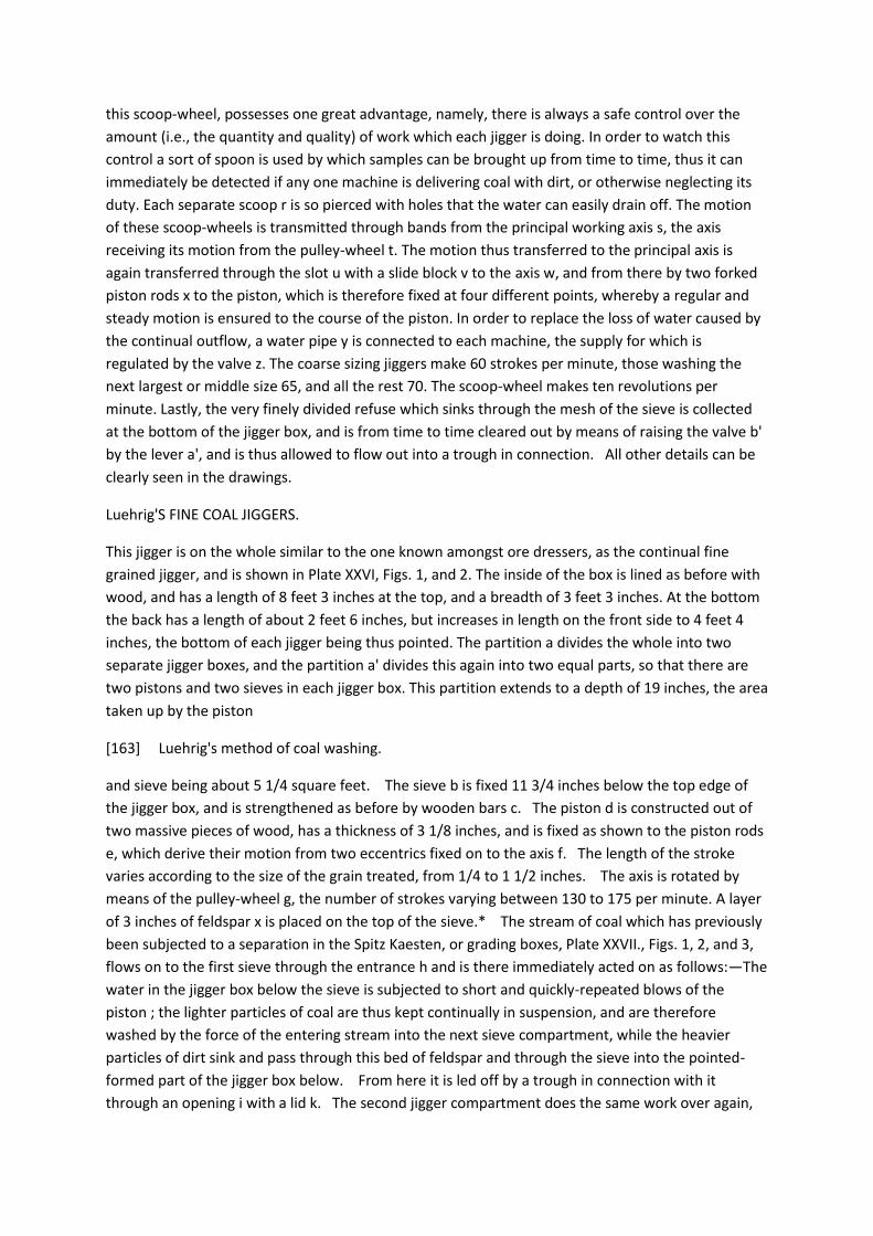
this scoop-wheel, possesses one great advantage, namely, there is always a safe control over the
amount (i.e., the quantity and quality) of work which each jigger is doing. In order to watch this
control a sort of spoon is used by which samples can be brought up from time to time, thus it can
immediately be detected if any one machine is delivering coal with dirt, or otherwise neglecting its
duty. Each separate scoop r is so pierced with holes that the water can easily drain off. The motion
of these scoop-wheels is transmitted through bands from the principal working axis s, the axis
receiving its motion from the pulley-wheel t. The motion thus transferred to the principal axis is
again transferred through the slot u with a slide block v to the axis w, and from there by two forked
piston rods x to the piston, which is therefore fixed at four different points, whereby a regular and
steady motion is ensured to the course of the piston. In order to replace the loss of water caused by
the continual outflow, a water pipe y is connected to each machine, the supply for which is
regulated by the valve z. The coarse sizing jiggers make 60 strokes per minute, those washing the
next largest or middle size 65, and all the rest 70. The scoop-wheel makes ten revolutions per
minute. Lastly, the very finely divided refuse which sinks through the mesh of the sieve is collected
at the bottom of the jigger box, and is from time to time cleared out by means of raising the valve b'
by the lever a', and is thus allowed to flow out into a trough in connection. All other details can be
clearly seen in the drawings.
Luehrig'S FINE COAL JIGGERS.
This jigger is on the whole similar to the one known amongst ore dressers, as the continual fine
grained jigger, and is shown in Plate XXVI, Figs. 1, and 2. The inside of the box is lined as before with
wood, and has a length of 8 feet 3 inches at the top, and a breadth of 3 feet 3 inches. At the bottom
the back has a length of about 2 feet 6 inches, but increases in length on the front side to 4 feet 4
inches, the bottom of each jigger being thus pointed. The partition a divides the whole into two
separate jigger boxes, and the partition a' divides this again into two equal parts, so that there are
two pistons and two sieves in each jigger box. This partition extends to a depth of 19 inches, the area
taken up by the piston
[163] Luehrig's method of coal washing.
and sieve being about 5 1/4 square feet. The sieve b is fixed 11 3/4 inches below the top edge of
the jigger box, and is strengthened as before by wooden bars c. The piston d is constructed out of
two massive pieces of wood, has a thickness of 3 1/8 inches, and is fixed as shown to the piston rods
e, which derive their motion from two eccentrics fixed on to the axis f. The length of the stroke
varies according to the size of the grain treated, from 1/4 to 1 1/2 inches. The axis is rotated by
means of the pulley-wheel g, the number of strokes varying between 130 to 175 per minute. A layer
of 3 inches of feldspar x is placed on the top of the sieve.* The stream of coal which has previously
been subjected to a separation in the Spitz Kaesten, or grading boxes, Plate XXVII., Figs. 1, 2, and 3,
flows on to the first sieve through the entrance h and is there immediately acted on as follows:—The
water in the jigger box below the sieve is subjected to short and quickly-repeated blows of the
piston ; the lighter particles of coal are thus kept continually in suspension, and are therefore
washed by the force of the entering stream into the next sieve compartment, while the heavier
particles of dirt sink and pass through this bed of feldspar and through the sieve into the pointed-
formed part of the jigger box below. From here it is led off by a trough in connection with it
through an opening i with a lid k. The second jigger compartment does the same work over again,

in order to cleanse the whole satisfactorily, namely, to separate more perfectly any fine dirt particles
which may have washed over with the coal. A stream of clear water runs in continually by a pipe I,
which can be regulated by a valve as shown. The washed coal flows out of the jigger box by the
outlet m, and is subsequently treated as described hereafter.
RITTINGER'S SPITZ KAESTEN, OR GRADING BOXES.
The classification of the fine grain, i.e., that below 1/4 inch, on screens or sieves, would create too
many difficulties to make it practicable, so that it becomes necessary to sort it first, and then it is
easily classified on the fine coal jiggers. This sorting can be effected in various ways, the best of
which is by the employment of Rittinger's Spitz Kaesten, Plate XXVII., Figs. 1, 2, and 3. These consist
of a series of two hopper-shaped or pointed boxes of a pyramidical shape, with a rectangular base.
The dirty coal and water flow into the first and smallest box, and pass out of the last and
* The object of this bed of feldspar is to act as a sieve, the flow of water causing the pieces of
feldspar to separate from one another for a few seconds, the grains of dirt having about the same
specific gravity as feldspar fall through the intermittent spaces. A sieve could not do this work as the
holes would have to be very fine and consequently would soon get filled up, so in this way the sieve
itself can be made of much larger mesh.
[164] LUEHRIG'S METHOD OF COAL WASHING.
largest one. The heaviest particles thus sink in the first box, and the next heaviest in the next; so that
the water flows out of the last box with very little coal in suspension. The grains thus sorted flow out
of the bottom of the boxes in a concentrated stream through the outlet troughs shown in the
drawings on to the fine grained jiggers just described.
Having described in detail the construction and action of the principal machines used in Luehrig's
Coal Washing Establishment, it now remains to give a general sketch of the whole system of dressing
as practised at the Brueckenberg Colliery (shaft No. 2), Saxony. See Plates XXVIII., XXIX., and XXX.
DESCRIPTION OF THE SYSTEM OF DRESSING.
The coal, as brought from the pit, is either taken to the washing apparatus in a mixed condition of
large and small, or, if divided underground into large and small, the latter only is washed.
If the latter plan is adopted at collieries where a large amount of round is made, the washing
apparatus is saved a great deal of work. At the Brueckenberg Colliery, where the coal is separated
underground, from six to twelve per cent, of the total quantity drawn is round (which amounts to
400 or 450 tons per day), of which only from 350 to 400 tons are washed or dressed.
This coal is tipped by means of circular tips or kickups a upon screens b, where pieces larger than 3
1/4 inches are separated from the remaining mass. In the modern washing establishments Briart's
patent screens are used, the bars of which are worked separately backwards and forwards by their
being attached to eccentrics on a revolving axle running at right angles to the bars ; the advantage
being that the screens can be placed at a less angle than the ordinary screens, gaining thereby a
larger screening surface.
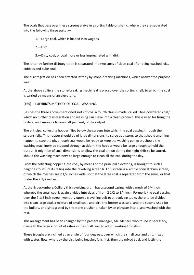
The coals that pass over these screens arrive in a sorting table or shelf c, where they are separated
into the following three sorts :—
1.—Large coal, which is loaded into wagons.
2.—Dirt.
3.—Dirty coal, or coal more or less impregnated with dirt.
The latter by further disintegration is separated into two sorts of clean coal after being washed, viz.,
cobbles and cube coal.
The disintegration has been effected latterly by stone-breaking machines, which answer the purpose
well.
At the above colliery the stone-breaking machine d is placed over the sorting shelf, to which the coal
is carried by means of an elevator e.
[165] LUEHRIG'S METHOD OF COAL WASHING.
Besides the three above-mentioned sorts of coal a fourth class is made, called " fine powdered coal,"
which no further disintegration and washing can make into a clean product. This is used for firing the
boilers, and amounts to one-half per cent, of the output.
The principal collecting hopper f lies below the screens into which the coal passing through the
screens falls. This hopper should be of large dimensions, to serve as a store, so that should anything
happen to stop the pit, enough coal would be ready to keep the washing going; or, should the
washing machinery be stopped through accident, the hopper would be large enough to hold the
output. It might be of such dimensions to allow the coal drawn during the night shift to be stored,
should the washing machinery be large enough to clean all the coal during the day.
From the collecting hopper f, the coal, by means of the principal elevator g, is brought to such a
height as to insure its falling into the revolving screen h. This screen is a simple conical drum screen,
of which the meshes are 2 1/2 inches wide, so that the large coal is separated from the small, or that
under the 2 1/2 inches.
At the Brueckenberg Colliery this revolving drum has a second casing, with a mesh of 1/4 inch,
whereby the small coal is again divided into sizes of from 2 1/2 to 1/4 inch. Formerly the coal passing
over the 2 1/2 inch screen went dry upon a travelling belt to a revolving table, there to be divided
into clean large coal, a mixture of small coal, and dirt; the former was sold, and the second used for
the boilers, or disintegrated by the stone crusher q, taken by an elevator into o, and washed with the
rest.
This arrangement has been changed by the present manager, Mr. Menzel, who found it necessary,
owing to the large amount of ashes in the small coal, to adopt washing troughs i.
These troughs are inclined at an angle of four degrees, over which the small coal and dirt, mixed
with water, flow; whereby the dirt, being heavier, falls first, then the mixed coal, and lastly the
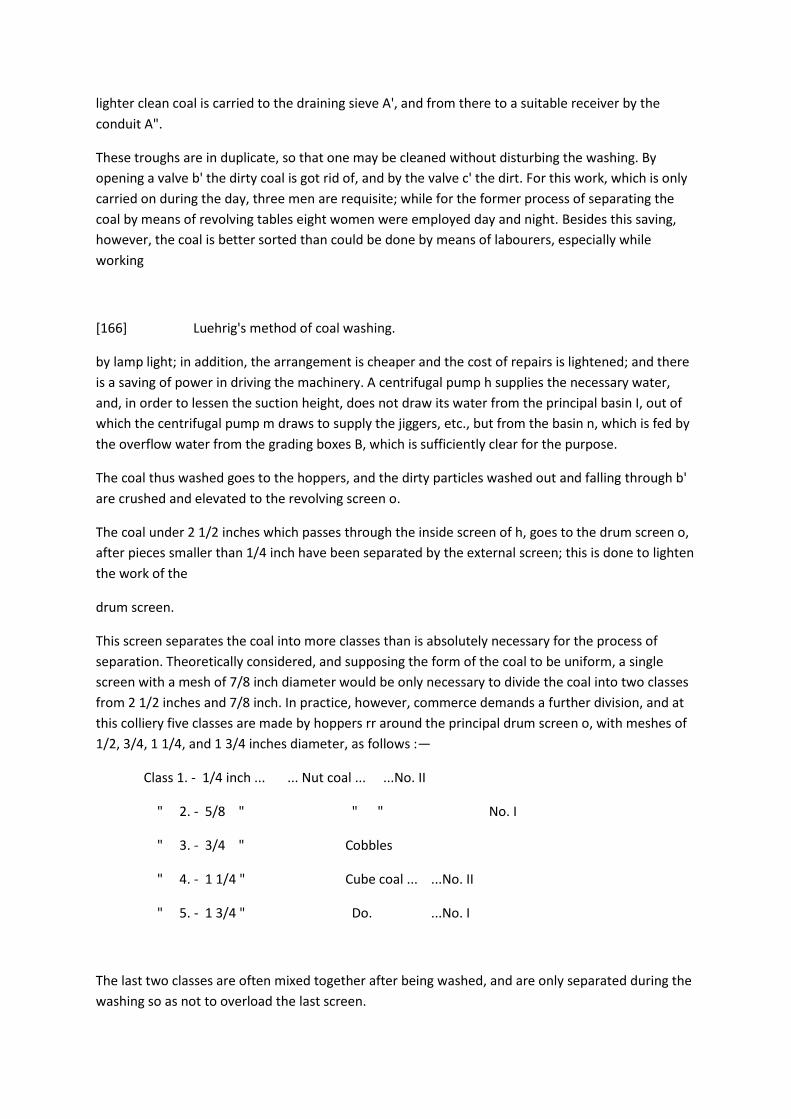
lighter clean coal is carried to the draining sieve A', and from there to a suitable receiver by the
conduit A".
These troughs are in duplicate, so that one may be cleaned without disturbing the washing. By
opening a valve b' the dirty coal is got rid of, and by the valve c' the dirt. For this work, which is only
carried on during the day, three men are requisite; while for the former process of separating the
coal by means of revolving tables eight women were employed day and night. Besides this saving,
however, the coal is better sorted than could be done by means of labourers, especially while
working
[166] Luehrig's method of coal washing.
by lamp light; in addition, the arrangement is cheaper and the cost of repairs is lightened; and there
is a saving of power in driving the machinery. A centrifugal pump h supplies the necessary water,
and, in order to lessen the suction height, does not draw its water from the principal basin I, out of
which the centrifugal pump m draws to supply the jiggers, etc., but from the basin n, which is fed by
the overflow water from the grading boxes B, which is sufficiently clear for the purpose.
The coal thus washed goes to the hoppers, and the dirty particles washed out and falling through b'
are crushed and elevated to the revolving screen o.
The coal under 2 1/2 inches which passes through the inside screen of h, goes to the drum screen o,
after pieces smaller than 1/4 inch have been separated by the external screen; this is done to lighten
the work of the
drum screen.
This screen separates the coal into more classes than is absolutely necessary for the process of
separation. Theoretically considered, and supposing the form of the coal to be uniform, a single
screen with a mesh of 7/8 inch diameter would be only necessary to divide the coal into two classes
from 2 1/2 inches and 7/8 inch. In practice, however, commerce demands a further division, and at
this colliery five classes are made by hoppers rr around the principal drum screen o, with meshes of
1/2, 3/4, 1 1/4, and 1 3/4 inches diameter, as follows :—
Class 1. - 1/4 inch ... ... Nut coal ... ...No. II
" 2. - 5/8 " " " No. I
" 3. - 3/4 " Cobbles
" 4. - 1 1/4 " Cube coal ... ...No. II
" 5. - 1 3/4 " Do. ...No. I
The last two classes are often mixed together after being washed, and are only separated during the
washing so as not to overload the last screen.

The coal, on entering the principal drum screen o, is met with a powerful jet of water for the
purpose of soaking it, and besides, each screen, half-way up the rising portion, is strongly squirted
with water to clear the coal sticking to the meshes, which quickens the classifying process. The
necessary amount of water is pumped by means of the pump m from the drainage troughs p of the
settling basins.
Besides the coal from the drum screen h, the drum screen o takes the mixture of coal and dirt that
falls through the hole b' of the washing troughs before described, which, after being disintegrated, is
lifted by means of an elevator. The five classes are brought through the hoppers r to the five
jiggers s below. These jiggers deliver the
[167] Luehrig's method of coal washing.
dirt which sinks on the screen, which is heavy enough to resist the upward motion of the water, and
which passes through an opening in the side, and by means of a bucket wheel is taken away and
allowed to fall into a passage t Usually the jiggers pass the dirt to the dirt heap either upon a
horizontal passage or by means of an Archimedian screw, but here the dirt is brought from each
jigger by passing down a steep passage t in the dirt hopper u, when, by means of the elevator v, it is
brought to a place where it can be taken away.
The dirt which falls through the meshes of the screen upon the bottom of the jigger, and passes the
valve b', Plate XXV, also goes into the passage t.
At last the jigger delivers the washed coal with mud. The mud, or fine coal and water mixed, is dealt
with according to the manner in which the drum screen screens the coal. If the drum screen
separates the fine coal from the rest, then the amount of mud in the jiggers is small; if this is not the
case, then the first jigger receives the greatest amount of mud which is required for the fine grain
jiggers.
Both coal and mud pass through a slit in the side of the jigger, and from there are dealt with in
different ways. In the old method a slanting sieve z' was placed to allow the water to pass through
and the coal to be brought to a hopper z, or if there was no room below this, a small elevator took
the coal to a loading hopper and an elevator was necessary for each jigger, or for each separate sort
of coal.
Instead of this transport arrangement, which gave great trouble and expense in repairs, the present
method, invented by Mr. Berg, simplifies the process materially. Here the mud and water are used
for transport, as with the washed coal they pass over passages inclined at an angle of four degrees,
the coal being separated by a sieve from the water just before entering the loading hoppers. At the
Brueckenberg Colliery the arrangement is as follows :—
The passage w brings the water and coal along to a sieve x, by means of which the fine coal
separated from the water falls into the hopper y, and if the sieve x has meshes only allowing coal
and dirt below 1/4 inch to pass, the fine coal and water pass direct to the fine coal jiggers; when,
however, the mesh of the sieve is larger, a class of coal too good for the fine coal jiggers is passed
through the sieve. In such cases the muddy water that escapes is passed over a sieve with a mesh of
1/4 inch, and is then caught by an elevator and mixed with the nut coals.

The mud, coal, and water passing through this screen are brought
[168] Luehrig's method of coal washing.
through the passage A to the pyramidical boxes B ; into these boxes also comes the coal by a
passage C from the 1/4 inch outer screen of the revolving screen h, which already has been
thoroughly soaked with water.
In cases where the fine coal is very much mixed with dirt, as at Brueckenberg, another coarse coal
jigger is placed in the mud stream for the purpose of taking away a great part of the coarse dirt
before the mud reaches the pyramidical boxes B and B'. This jigger is not shown in the drawing. The
pyramidical boxes deliver, first, a quantity of grains of coal and dust; secondly, water which passes
along the passage D and which holds in suspension the finest particles of coal and dirt, part of which
is used for the feeding of the centrifugal pump h, mentioned before, while the remainder flows into
the settling basins. From each pyramidical box the coal and dirt fall into the fine coal jiggers, so that
for each box such a jigger is required. In this case there are two, E being fed from the box B, and E'
from box B'. In these jiggers the feldspar separates the coal from the dirt; the former mixed with
water passes along the passage F over a sieve to a hopper G, out of which, by means of a Jacob's
ladder H, the buckets of which are pierced with holes, to a loading or reserve hopper. Should the
mud contain fine divided particles of iron pyrites, a sieve is introduced, with a mesh of about 1/32
inch wide; when this is elevated it is necessary to squirt clean water into the buckets by means of a
hose.
The mud that passes through the sieves is taken to the depositing basins.
Along the passage J pass at last the dirt and mud from the mud jiggers to the dirt basin u, where,
with the rest of the dirt from the coarse coal jiggers, they are lifted by means of an elevator v.
During the work water is constantly flowing from the cistern K, which is fed by the centrifugal pump
m through the pipes L to all the jiggers.
Finally, it may be mentioned that the steam engine M of 25 horsepower works the whole of the
apparatus. At present, however, the washing is only done during the day, there not being enough
work to keep all going during the night. The screens b, the crusher d, and the elevator e are worked
by means of a small engine, not shown in the drawings, during the night.
The coal as brought from the mine, being assayed before washing, gives 25 per cent, ash (pieces of
pure coal contain 2.3 per cent. ash). This high percentage is reduced to 5 or 6 per cent, by washing,
so that from 19 to 20 per cent, of the dirt is got rid of; thus 2.7 to 3.7 per cent., or, taking as a
medium, 3.2 still remains as impurity in the coal. Coal care-
[169] LUEHRIG'S METHOD OF COAL WASHING.
fully cleansed by hand only gave .1 per cent. less ash, so that the highest possible degree of
cleansing seems to have been attained. The remaining impurity of 3.2 per cent, is made up chiefly
from thin plates of calcspar and iron pyrites adhering to the coal, and not from free pieces of dirt.
The total consumption of water consists of 660 gallons, with an addition of 22 gallons of fresh water
per minute—that is, 50 gallons of water are required for one cwt. of coal. M. Luehrig has guaranteed

to wash 800 cwts. of coal per hour with a maximum of 6 per cent, of ash, the coal ranging from 1/2
inch downwards, for making coke. These results have been perfectly attained.
Table of reaults at Brueckenberg (Shaft no. 2)
[table]
The following table shows the wages given in the coal-dressing establishment:--
[table]
[170] DISCUSSION—LUEHRIG'S METHOD OF COAL WASHING.
From the foregoing table the average of these four months would be about one-tenth of a penny per
cwt. for labour. M. Luehrig quotes the price of his coal-washing establishments, with a capacity for
washing 1,000 cwts. per hour during ten hours a day, including all extra plant, such as loading
apparatus, settling beds, etc., at £2,700 to £3,500. Taking a medium, therefore, of £3,100, and
reckoning the interest at 5 per cent., the amortization as 10 per cent., and the repairs at 5 per cent,
(total, 20 per cent, of the outlay, or £620 yearly), and reckoning 290 working days per year, the daily
cost would amount to 42s. 9d. a day; a little over .051 of a penny a cwt. for depreciation of plant and
interest of capital, or threepence a ton for labour, depreciation, and interest on capital.
The output of the various classes of washing can be gathered from the following Table :—
[table]
Plate XXXI. shows in the form of a diagram the way the coal is passed through the several screens
and machines.
The Chairman, in proposing a vote of thanks to Mr. Rathbone for his paper, drew a comparison
between the very exhaustive method of treating the coal at Zwickau and the very primitive
appliances that were first introduced in England, where a large quantity of coal was lost in order to
cleanse the remainder of about 18 per cent, of the rubbish it contained. Even the very much more
perfect arrangements introduced from France by the late Mr. James Morrison did not come up to
the standard of perfection now described. But before introducing machinery of so costly a
description it would be as well to consider if the amount of water required, which seemed to be very
large, would not exceed that which might be readily attainable, and also whether the cost of
cleaning would not be too high to render the arrangement of practical use in England.
[000 between pages 170 and 171
Plate XXV. To illustrate Mr. E.P. Rathbone's paper on "Luehrig's Coal Washing Machinery". Figs. 1 -
3, Luehrig's Coarse Coal Jigger.
Plate XXVI. To illustrate Mr. E.P. Rathbone's paper on "Luehrig's Coal Washing Machinery". Figs. 1 - 2
Luehrig's Fine Coal Jigger

Plate XXVII. To illustrate Mr. E.P. Rathbone's paper on "Luehrig's Coal Washing Machinery". Figs. 1 -
3, Rittinger's Spitz-Kaesten or Grading Boxes.
Plate XXVIII. To illustrate Mr. E.P. Rathbone's paper on "Luehrig's Coal Washing Machinery".
Longitudinal section.
Plate XXIX. To illustrate Mr. E.P. Rathbone's paper on "Luehrig's Coal Washing Machinery". Cross
section.
Plate XXX. To illustrate Mr. E.P. Rathbone's paper on "Luehrig's Coal Washing Machinery". Plan.
Plate XXXI. To illustrate Mr. E.P. Rathbone's paper on "Luehrig's Coal Washing Machinery". Diagram
showing the distribution of the coal.]
[171] INSTRUMENTS FOR THE DETECTION OF GAS.
Mr. W. Cochrane, in seconding the vote of thanks, referred to the tabular statements which had not
been read, but which conveyed a great amount of valuable information.
The vote of thanks was unanimously responded to; and the members adjourned to the Laboratory of
the College of Physical Science, kindly placed at their disposal by Professor Freire-Marreco, to hear
Professor Forbes, of Anderson's College, Glasgow, describe his instrument for ascertaining any small
quantity of gas there might be in the workings of a mine.
Professor Forbes stated that his attention had been first drawn to the subject by his friend Mr.
James Young, F.R.S., of Kelly, shortly after the disastrous Blantyre explosion in 1877. The form the
first suggestions took was not very practical, but they afterwards became elaborated into the
convenient and practical instrument he had the honour now to exhibit.
[diagram]
This instrument depended on a well-known principle in acoustics : that the sounds produced by the
vibration of a tuning fork placed over a column of air confined in a tube would become very much
more audible when the column in the tube was of the length suited to the pitch of the note
produced by the fork, and that the length of this column was influenced by the specific gravity and
nature of the various gases which the tube might contain. The instrument (see woodcut) was
therefore composed of a tuning fork, a, placed over a tube b, the length of which is regulated by a
piston d, moved up and down by a rack and pinion actuated by a large milled head c, the amount of
motion given to which is indicated by a pointer. When used the metal rod e is inserted between the
limbs of the fork and drawn sharply through them, and the vibrations thus caused become distinctly
audible only when the tube is of suitable length. If, therefore, the fork which was audible with a
certain length of tube ceases to be so, it shows that the condition of the air in the tube has
undergone a change, and become either more or less mixed with gases of different specific gravities,
and the amount of such change is indicated by the pointer. If, therefore, the air is contaminated with
fire-damp, the mixture will be of different quality to, and less specific gravity than, pure air, and the
tube
172 INSTRUMENTS FOR THE DETECTION OF GAS.

will have to be lengthened to cause the vibration of the tuning fork to be audible; and if a properly
graduated index is fitted to the tube, this amount of increase in length may be made to indicate the
exact amount of firedamp in the mixture.
A correction has to be made for temperature, variations in which also affect the column of air, and
to make these corrections, a thermometer, f, was attached to the instrument; this thermometer was
not graduated in degrees in the usual way but registered certain variations in figures which
corresponded with and had to be subtracted from the figures, showing the length of the tube and
the amount of the fire-damp, the result giving the correct percentage of fire-damp in the tube.
In order to give to the hand greater control over the lengthening and shortening of the tube, a rack
has been attached to the piston, which works in a pinion on whose axis there is a large disc, c, with a
milled head 3 inches in diameter. This disc has a glass face with a graduated scale round the
circumference; so that a fixed index marks with great precision the exact length of the tube. The
scale is thus made so large that readings can be made in the feeblest light.
That the instrument may be taken in advance of a lamp in places where gas is expected in large
quantities, a phosphorescent powder is placed in a cavity behind the graduated glass plate, so that
readings can be taken in the dark.
To be sure that the gas or air in the tube is the same as what is to be found in the particular part of
the mine under examination, there is introduced, through the piston worked by the pinion, a rod, at
the upper end of which is a packed disc fitting the tube tightly. Previous to taking a reading this disc
is, by means of a handle attached to the rod, driven up to the open end of the tube, and when
drawn back it sucks in the air from the place under observation, and by a single turn of the handle,
locked to the piston which works the pinion, by a bayonet joint.
The following is a description of the apparatus used for testing the accuracy of the scale:—A circular
trough 4 feet diameter and 3 inches deep, was partially filled with water, and a grating placed over
the water to stand upon. In the centre of the trough there was a hole with an inch metal tube
projecting upwards 4 inches. To this was attached an India-rubber tube 2 feet long, with a
mouthpiece which could be firmly attached to the mouth for breathing. The operator sat on a stool
above the water with the mouthpiece attached, and the nose closed by spring pincers, and a tin
cover 4 feet high and 3 feet diameter was lowered over him into the water. There was a small hole
in this cover, with glass over it, at which
[173] INSTRUMENTS FOR THE DETECTION OF GAS.
a light was held on the outside. Different quantities of marsh gas were then admitted under the
cover, which were mixed with the air by means of a fan. A reading was taken with the instrument,
and at the same time a bottle of water was emptied and closed air-tight. The contents of the bottle
were afterwards analysed; and thus the true percentages, corresponding to different readings of the
scale, were obtained.
In this way it is possible to measure the proportion of fire-damp to about one-half per cent, of the
volume of the mixture.

These experiments had been verified by his colleague, Professor Dittmar, who at different times had
analysed the contents of the bottles filled in the cylinder and had found them to agree within one-
half per cent, of the readings of the indicator, and this seemed at present to be the limit to which a
practised ear could reach in using the instrument.
Experiments were then made before the members showing that amounts of gas varying from a trace
to 20 per cent, could be readily detected by the instrument.
Professor Forbes continued—Where carbonic acid gas was present in the mine it of course increased
the specific gravity of the mixture, and modified the indication on the instrument. But the choke-
damp diminished the explosiveness of the fire-damp in about the same proportion; for example, if
there was a mixture of 6 1/2 per cent, of fire-damp and 1 per cent, of carbonic acid gas, the
instrument would indicate a figure due to about 4 per cent, of fire-damp; and as a mixture of 6 1/2
per cent, of this gas with the atmosphere is explosive and 4 is not, this alteration in the reading
would be very serious were it not that the presence of the carbonic acid gas rendered the mixture as
harmless as it would have been had it only held the 4 per cent, of fire-damp indicated by the
instrument, as, to use an expression common among the miners of Scotland, the carbonic acid gas
"damped" the marsh gas. Of course the instrument could be made to indicate the absolute quantity
of marsh gas even when carbonic acid gas was present, by adding an apparatus whereby the mixture
to be examined could be passed through water before it entered the tube of the machine and the
carbonic acid gas absorbed, but he con-
[174] INSTRUMENTS FOR THE DETECTION OF GAS.
sidered from the above reason that such an addition was perfectly unnecessary, and would only
serve to render the apparatus more cumbersome, while at present it was one of extreme simplicity,
and could be worked by any one with ease and accuracy. Moreover, Dr. Angus Smith had shown that
2 per cent, of carbonic acid gas extinguishes a candle or lamp.
He had taken the instrument down many mines, and one remarkable fact had been elicited by its
use, namely, the very uncertain nature of any test for gas made by a Davy, a Clanny, or any other
safety-lamp. He had tested many such lamps and found they would not show a blue cap when 5 per
cent. of marsh gas was present; and he really thought, as a matter of fact, these lamps were not
sufficiently delicate to be relied on.
The Chairman said, he was sure that they would all join in a vote of thanks to Professor Forbes for
the trouble he had taken in bringing his very clever invention before them, and for the very
interesting illustrations he had exhibited, and he hoped that the instrument would be the means of
initiating valuable researches in mines which are more or less subject to great discharges of gas.
Mr. A. L. Steavenson, in seconding the vote of thanks, said that he was the first to ask Professor
Forbes to come over, and he felt very much obliged to him for the courteous way in which he had

acceded to the request. It was of the utmost importance to all persons who had devoted their
attention to the perfection of such instruments that they should be freely criticised by those whose
calling it was to use them. One of the chief uses of such a machine was to enable the engineer of
the colliery to rightly estimate the amount and nature of the gases in the air returns so as to
ascertain if there was any deficiency in the ventilation, and he thought that an instrument which
only indicated that the air in the mine approached more or less to the explosive points without
indicating the percentage of fire-damp was imperfect in a very important particular, and, therefore,
he considered the Professor's explanation of the nature of the indications, when carbonic acid gas
was present, hardly satisfactory, and any machine which might, under circumstances very likely to
occur, register only 4 per cent, of gas when 6 per cent, of fire-damp was present, was scarcely to be
relied upon, and in this respect he thought the invention of Mr. Liveing, described in page 287, Vol.
XXVII. of the Proceedings, much superior. This instrument, even when carbonic acid gas was present,
indicated one-
[175] INSTRUMENTS FOR THE DETECTION OF GAS
fourth per cent, of marsh gas with unerring certainty. The Professor's instrument was, however,
decidedly the most handy and portable, but he thought the results obtained by that of Mr. Liveing
were more reliable.
Mr. John Cooke thought that changes in the barometrical pressure might influence the readings of
the instrument, and would be glad to hear more at length from the Professor the reason for
supposing this not to be so. He would also like to know the price of the instrument.
Professor Forbes, in replying to Mr. Cooke, said that it must be recollected that the instrument was
simply a machine for registering the velocity of the sound wave which depended on the elasticity
and density of the medium through which it is transmitted, and as any increase or decrease in the
density of any given medium is accompanied with a corresponding increase or decrease in its
elasticity, the velocity of sound will always be the same under any pressure in the same medium,
although susceptible of great variation when the component parts of the medium are changed. With
regard to the second question, the price of the instrument was £10.
Mr. Liveing then exhibited the instrument he had invented. He stated that he had frequently tested
the instrument both above ground and in the workings of a pit, and found that it invariably detected
quantities of gas to a quarter per cent. He found that the presence of carbonic acid gas, to the
extent of 2 per cent, in the mixture experimented upon, did not practically alter the reading. The
point to be remembered was that the instrument gives the heating value of the gaseous mixture
examined, or in other words, its approach towards the explosive point; the presence of carbonic acid
gas only affects the readings to the extent that it diminishes the heating value. In the case,
however, of an instrument dependent on the physical properties of the mixture (as was Professor
Forbes') the presence of carbonic acid affected the reading, but not in the same ratio as it affected
the heating value.
The vote of thanks to Professor Forbes having been unanimously adopted, the meeting terminated.
[176 BLANK PAGE]
[177] PROCEEDINGS.
PROCEEDINGS.
GENERAL MEETING, SATURDAY, APRIL 17th, 1880, IN THE WOOD MEMORIAL HALL, NEWCASTLE-
UPON-TYNE.
J. B. SIMPSON, Esq., in the Chair.
The Secretary read the minutes of the last meeting and reported the proceedings of the Council.
The following paper "On the Strength of Wrought Iron in Compression," by Mr. Wigham Richardson,
was then read:—
[178 blank page]
[179] ON THE STRENGTH OF IRON IN COMPRESSION.
ON THE STRENGTH OF WROUGHT IRON IN COMPRESSION.
By WIGHAM RICHARDSON.
The writer hesitates to some extent in bringing the above subject before the members of the
Institute, seeing that he has no new facts, data, or experiments to lay before them; but he wishes to
express some doubts about generally received hypotheses, and, in so doing, to invite discussion and
an interchange of ideas.
It is now nearly twenty-five years ago since Professor Eaton Hodgkinson made certain remarks
before the writer on the premises of University College, London, where he made his experiments,
and it is to these remarks that attention is called.
Professor Hodgkinson, whose experiments are even now the generally accepted data for all
deductions about the strength of wrought iron in compression, then said to his class—" Remember
that although a piece of wrought iron one and a-half inches long and three-quarters of an inch
diameter will crush with a load of something like sixteen tons per square inch, we do not know, if the
sectional area be increased, that the limit of crushing strength will be increased in the same
proportion."
This is the remark of the Professor, and yet the writer thinks that he would be correct in saying that,
notwithstanding this, the usual practice of engineers has been to consider wrought iron as weaker in
compression than in tension, whatever the section of the structure may be, and justified in asking, is
this common sense ? For instance, a tall chimney may be built of bricks without crushing the lowest
course of its brick-work, but if a little pillar, one inch square and two and a-half inches high, were to
be sawn out of a brick, such a little pillar would not support the proportion of the load due to it. It
would crumble to pieces. In other words, twenty square inches of brick are more than twenty times
as strong as one square inch. Perhaps a more striking illustration would be this: When any
excavation is going on it is usual to leave here and there cones of the supersoil to mark the original
height of the ground. These cones, if of
[180] ON THE STRENGTH OF IRON IN COMPRESSION.
small diameter, are most readily crushed, but if they are left so as to be two or three feet in
diameter for every foot of height, they will bear many tons weight with safety.
One of the most recent works on the strength of structures is that written for the " Science Text
Book" series, by Mr. John Anderson, the well-known Director of the Woolwich Arsenal, and he thus
describes the effect of crushing wrought iron cylinders when the load is taken off before fracture:—
" By increasing the stress upon these short cylinders of wrought iron or soft steel, they are found to
shorten gradually by bulging outwards in the middle. The effect of this change of form is to slightly
stiffen the metal, and this affects the malleable or flowing property; unless the specimen is
extremely soft it will soon show symptoms of slight fissures or cracks at the part which is bulging. To
prevent this the annealing process must be resorted to, and with care the pillar can be flattened
down to a thin disc, gradually presenting a larger surface for the machine to act upon. Reckoning the
intensity of the ultimate pressure from the original dimensions a stress of upwards of 100 tons per
square inch is necessary to actually flatten down wrought iron."
When Professor Hodgkinson was making his experiments he did not, so far as is known, try the
annealing process, at least those cylinders which the writer saw tested were actually broken. They all
broke in the same way; a bulging out at or below the middle, and then a kind of telescopic shutting
up, the lower part an irregular cone, the upper part being hollow. Plate XXXII., Fig. 1.
In these experiments the cone was always on the lower side, but it did not seem very clear why this
should be the case.
Looking again at Fig. 1, it is evident that if these small pillars had been hexagonal, and several
standing close together and held together, they would have given each other much mutual support,
and the initial bulging would have been checked.
If this be admitted, the difficulty of calculating the strength of any structure in compression is not
lessened. It is easy to speak of so much per square inch if only the strength did not increase in a
more rapid ratio than the section.
Although wrought iron is commonly supposed to be weaker in compression than in tension, perhaps
no one has ever seen a case in actual practice of wrought iron being crushed. In some cases it is
difficult to conceive that pieces of machinery would break as they do, if iron were really weaker in
tension than in compression. For example, the writer
[181] ON THE STRENGTH OF IRON IN COMPRESSION.
remembers seeing an eccentric rod break in consequence of the slide valve seizing. The engine was
making at least one revolution each second, and therefore there was a pulling and a crushing strain
rapidly repeated. Notwithstanding this the eccentric rod, which was of excellent iron, had drawn
out, like a piece of dough or putty, and then broken.
Mr. John McFarlane Gray, of the Board of Trade, wrote a most valuable report upon the breaking in
two, at sea, of the paddle-wheel steamer " Mary," built on the Clyde, and he demonstrated that the
upper works gave way in compression and not in tension; but, at the same time, he showed that this

was not by crushing in the iron, but by repeated bulging and straightening, whereby the honest iron
was ultimately obliged to yield.
Again, a ship built on the Wear some ten or twelve years ago, when being towed down to the dock,
struck her mast against the bridge and it snapped off at the deck, but there was not any appearance
of crushing when the fracture was examined.
On another occasion at works close to those of the writer, the guy of the shear legs gave way, and
the legs, which were wrought iron tubes, snapped in two, but on the most careful examination of
the broken pieces no appearance of actual crushing could be detected.
The late Sir William Fairbairn, in his work on " Iron Ship-building," gives (pp. 47-63) an excellent
summary of the elaborate experiments which were made on the strength of iron tubes at the time
when the Menai Tubular Bridge was being designed. He gives a series of illustrations of the way in
which these tubes gave way, which, in every case was by bulging. Fig. 2 is a fair sample of these.
He also states that the strength of such columns varies as their widths multiplied by the cube of their
thickness.
Taken from his tabular list of circular tubes, the strongest of them, which was 10 feet long, 6 3/4
inches diameter, 1/8 inch thick, broke with a pressure of 16 tons per square inch. Taking then, Sir
William's own rule, if the tube had been 1/4 inch thick instead of 1/8 inch, it would have borne eight
times as great a load, eight being the cube of two, for the doubled thickness. But eight times 16 tons
equals 128 tons, and, dividing this by two, since there would be double the sectional area, it would
seem by the above rule that the iron would bear in compression 128/2 = 64 tons per square inch of
section ; and yet, further on (p. 62), he says, that in calculating the strongest possible form not more
than 16 tons per square inch must be reckoned on. This deduction seems to be perfectly
inexplicable.
[182] ON THE STRENGTH OF IRON IN COMPRESSION.
The writer has been told by a friend, a Cambridge wrangler, that Professor Clark Maxwell considered
that both tensional and compressive fractures could be resolved into sheering fractures, and that
broken iron might be assumed as coming asunder much as if two combs were stuck the one into the
other. Fig. 3.
If this be the case, is it not evident that, say a dozen comb teeth must be (in tension) just about
twelve times as strong as a single pair of comb teeth ? Fig. 4. But, on the other hand, is it not equally
clear that in compression the larger the number of such teeth the greater, relatively, must be the
strength.
It is usual now-a-days to speak of molecules, and the swinging or rotation of one molecule round
about another; perhaps such phraseology is neither more nor less accurate than the old style of
speaking of nature as abhorring vacuum up to 32 feet. However, be that as it may, let it be supposed
that these molecules are held together by some attractive force which is comparable to magnetic
attraction or to magnetic repulsion. Now every schoolboy knows that he can more easily take the
keeper off a magnet by sliding it than by pulling it straight off.

Take a series of molecules, Fig. 5, and let it be supposed that a fracture takes place along the line A
B. It is perhaps not unreasonable to imagine that if the fracture is effected by pulling asunder, i.e., by
tension, that two individual molecules would separate in some such way as is indicated by the
arrow, Fig. 6.
If, on the other hand, the fracture is effected by compression, that ths molecules would follow (or
strive to follow) the arrows in Fig. 7.
In either case the supposition is in accordance with what is often spoken of as the " angle of
fracture."
But it will be noticed that in compression the molecule which strives to follow the arrows, Fig. 7, will
come against, or come foul of, the molecules (shown by dotted circles) beyond, and that a series of
such molecules will give each other a mutual and cumulatively-increasing support.
The deduction from the foregoing reasoning would seem to be that it is inaccurate to speak of the
compressive strength of iron as being 16 tons (or any other number of tons) per square inch; that
iron is probably like water, incompressible if absolutely confined; and that between the strength of
3/4-inch bars and large masses there is an ever-varying measure of strength per square inch.
It might indeed be assumed that in practice it is very rare indeed to find iron absolutely crushed, and
that in actual experience, with reasonably designed structures, the strength of wrought iron in
compression is very
[183] ON THE STRENGTH OF IRON IN COMPRESSION.
far above the conventional 16 tons per square inch. If this be admitted, it will become apparent how
very necessary it is to study how to avoid the possibility of buckling.
This may be done in various ways. For example, in making wrought iron columns for sheer legs, a
large amount of belly in the centre will be very efficacious. Also, it is probably expedient in
compression to use the material in solid masses, rather than in the thinner plates which, on account
of the greater facility they afford for riveting together, make them superior in tension.
In the writer's special branch, that of building steamers, the deductions above arrived at cut in two
ways. If a ship is regarded as a girder, and it be estimated that a certain compressive stress will come
on an iron deck, then the importance of " keelsoning" the deck beams, or introducing a series of
longitudinal stiffeners, as suggested by Mr. William Denny, of Dumbarton, becomes at once
apparent; while, on the other hand, if a much higher value can be given to the strength of wrought
iron in compression than is usually assigned, then, perhaps, the strength which is commonly found
at the gunwale, namely, in the stringer plate and angle, and in the shear strake, may be a full
equivalent for the tensional strength of the other member of the girder.
In fact, one of the causes which led the author into this line of thought, was the observing of the way
in which iron vessels break up when stranded, that is to say, almost always in tension, or, as far as
his own observation went, always in tension.
A further deduction is, that if this suggestion is pushed to an extreme, and, in mathematical phrase,
the strength of iron in compression supposed to be infinite, then, under that supposition, the neutral

axis of a girder can no longer be considered as somewhere about the middle depth, but, on the
contrary, must be taken as at the bottom of the girder, or say along the centre of the lower flange.
This theory, which the writer enunciates with the greatest deference (if correct), would just about
double the computed strength of simple girders, and would explain what has often seemed
perplexing in estimating the strength of some ships whose scantlings have appeared to him
insufficient, or barely sufficient, to withstand the strains to which they undoubtedly have been
subjected.
It is, however, in bridge building that this subject acquires supreme importance, and the writer
would gladly see a wider recognition of the compressive strength of wrought iron leading to an
abandonment on the part of engineers of the system of girder bridges rather than see it lead to
[184] ON THE STRENGTH OF IRON IN COMPRESSION.
the adoption (in girders) of a lower factor of safety. A girder bridge is open to many objections. In
the first place, so long as the top and bottom members are made nearly equal, the one in
compression, and the other in tension, there is twice as much material as would be necessary if the
tension were taken by thrust against abutments. In a bowstring girder there is both the weight of
the bow and the weight of the cord or string. If the span be considerable the principal load which the
bridge has to bear is the bridge itself, so that an increase of weight adds in a geometrical ratio to the
tensional stress. But perhaps a greater objection to the girder is that provision must be made for
expansion and contraction, whereas an arch would rise and fall within itself. Nor is this all, the
necessity of providing a certain amount of play for expansion leads to the girder being set down on
the top of the piers instead of being bound in with them in the way that the haunches of a stone
bridge spring from the abutments. There is little doubt that this was at least one cause of the giving
way of the Tay Bridge.
In this immediate neighbourhood there are a great variety of types of bridges, and all of them are
worthy of study. Over Dean Street is one of the noblest, if not the noblest, stone arch in the world. It
was designed, the writer believes, by the present Engineer of the North-Eastern Railway, Mr.
Thomas E. Harrison, under the late Robert Stephenson. At Sunderland is the fine cast iron arch,
planned by Burdon, and afterwards stiffened by Stephenson, with arched wrought iron boxes to give
lateral stability. Close alongside is the new Railway Bridge, a bowstring girder, but who designed it,
or what considerations led to this type being adopted, the writer does not know. The High Level
Bridge, by Stephenson, is sui generis, while the Redheugh Bridge will perhaps hereafter be criticised
rather than imitated. At Scotswood is the extremely elegant Suspension Bridge, the work of the
brothers Green, who also, the writer believes, designed the Ouseburn and Willington Viaducts,
which were wooden arches on stone piers. These have since, with consummate skill, been altered
into wrought iron arches, and they come more nearly to the ideal of a wrought iron bridge purely in
compression than any other in the district, although the bridge crossing the Tyne at Wylam is, so far
as its arch is concerned, a much more scientifically calculated and appropriate structure. This Wylam
Bridge was designed by Mr. William Laws, of this town, who read a description of it before the
Institution of Civil Engineers (Session 1878-79), in which he very moderately puts forth some, but
perhaps not all, of the merits of his design. The principle on which the Wylam Bridge was
constructed has also been adopted by Sir J. W.
[185] DISCUSSION—STRENGTH OF IRON IN COMPRESSION.
Bazalgette in his design for the Tower Bridge, and in a design for a bridge over the Forth recently
published in
"Engineering " by Mr. Am Ende.
There are two other bridges in this district which, though hardly relevant to the subject of this paper,
are well worthy of remark; the Swing Bridge, designed, the writer believes, by Mr. John F. Ure and
Mr. Percy Westmacott, and the Byker Bridge, with its brick arches, the work of the late Mr. Hodgson.
The writer is desirous of inviting the members of this Institute to study these various types of
bridges, to reflect on the respective cost of the foundations, piers, and abutments on the one hand,
and of the superstructure on the other, and to consider how their ideas would be modified if once it
were conceded that wrought iron properly arranged may be very much stronger in compression
than in tension; and if, as it might seem, that wrought iron is a material which, when properly
arranged, has a greater solidity of resistance than even granite, with a special elasticity of its own, it
is not perhaps beyond a reasonable flight of fancy to imagine that rivers and ravines may be spanned
by structures as architecturally beautiful as true in construction, which shall last to be the admiration
of future ages.
Mr. Ross said, the subject of wrought iron in compression had not received that amount of
consideration it deserved. Although he did not altogether agree with the writer in thinking that
wrought iron in compression for either short or long columns could be made to stand as great a
strain as in tension; yet he remembered an experiment which came before his own observation
some time ago, which perfectly corroborated the statements of the writer of the paper—that a large
area of iron was proportionately stronger in compression than a small area. Mr. Latham's
experiments on riveting only gave for ordinary rivets a crushing strain of seven tons per square inch,
beyond which there was perceptible indentation. With regard to the construction of boilers, in many
cases the crushing strain seemed to be altogether neglected, although it was a very important
element; for instance, in the ordinary way of fastening 3/8-inch plates with 3/4-inch rivets, 1 3/4-
inch pitch, the portion in compression is .25 square inches, the section through one rivet is .44
square inches, while the area of plate in tension is .375. According to Mr. Latham's experiment, the
strength of the rivet would, therefore, be
[186] DISCUSSION—STRENGTH OF IRON IN COMPRESSION.
insufficient, and this seemed to be borne out in practice, for by double riveting, and putting more
metal in compression, the joint is increased in strength, although the area of plate in tension is
unaltered. For long columns unquestionably wrought iron had great strength and advantages over
cast iron. He thought the subject one of very great importance, and one deserving considerable
discussion.
Mr. Hawthorn said, he agreed with Mr. Richardson that the relative strength per square inch of
section of a large and solid mass of iron in compression would considerably exceed that per square
inch of a small mass, and that the former would resist more in compression than in tension—indeed,
under some conditions, wrought iron would carry in compression 60 or 70 tons per square inch
without injury. But in different structures, such as girders and pillars, it was not so much the iron
that gave way under compression, as from the buckling which ensued from errors in construction,
which destroyed the iron, not so much by crushing as by bending and tension, and he thought that
the application of wrought iron in compression might be much more advantageously employed than
at present, if all these circumstances were duly considered.
The Chairman thought they ought to pass a vote of thanks to Mr. Wigham Richardson for the very
interesting paper he had sent to them; and perhaps it would be well to reserve any further
discussion on the subject until Mr. Richardson himself could be present.
Mr. Hedley seconded the motion, which was carried unanimously.
Mr. James I'Anson read a paper, communicated by Professor A. Freire-Marreco, " On an Apparatus
for Preventing Over-Winding," as follows :—
[000 between pp186-7.
Plate XXXII. To illustrate Mr. Wigham Richardson's paper "On the strength of wrought iron in
compression". Figs. 1-7]
[000 blank page]
[187] APPARATUS FOR THE PREVENTION OF OVERWINDING.
APPARATUS FOR THE PREVENTION OF OVERWINDING.
By JAMES I'ANSON.
Communicated by Professor A. Freire-Marreco, M.A.
This arrangement, in common with the various detaching hooks, etc., now in use, has for its object
the prevention of accidents through overwinding; but it is sought in this case to accomplish the
desired object in a different way and at an earlier stage than in the case of the hooks and
contrivances commonly used.
The essential difference in the mode of procedure is this :—That whereas with the detaching hook
the cage is wound up more or less violently against some appliance by which the connection
between the cage and the rope is severed, the cage being left suspended independently of the rope;
in the present case it is sought to strike at the root of the evil by arresting the motive power as soon
as the cage has passed the point at which it ought to stop. This is accomplished by cutting the steam
off the engine, and simultaneously applying a steam brake by an automatic arrangement which is
brought into action by the cage itself as soon as it passes the proper stopping point. The way in
which this is accomplished is shown in Plate XXXIII., in which A is a steam-brake cylinder, into which
the steam is admitted by a piston-valve B. This piston-valve always has steam on its top side when
the engine is working, so that the steam is constantly endeavouring to open the valve and find
access to the brake cylinder. It is prevented from doing so, however, by the rod C and the crank D
attached to the valve piston-rod, and held in position by the lock E, which passes through guides and
through a slot in the end of the rod C, holding it in the position shown. The rod C is therefore always
in tension, and the moment the lock E is lifted, by the cage striking the curved lever F, the rod is
allowed to move in the direction of the arrow, and the steam at once gets access to the brake
cylinder, at the same time turning the throttle-valve G, to the spindle of which the crank D is keyed.
The steam is thus cut off from the engine and admitted to the brake simultaneously, and the engine
comes to rest before the cage can reach a position of danger.
[188] DISCUSSION—PREVENTION OF OVERWINDING.
It will be seen that if the engine be started the wrong way, the apparatus at once comes into
operation, and stops it. After it has come into operation, the cage remains suspended until the
steam is turned off at the boiler, and let out of the brake cylinder by a cock provided for that
purpose, when it is lowered gradually down on to the keps. All that is then needed is to replace the
lock, and until this is done the engine cannot be started, as the steam is cut off by the throttle valve
G; this ensures the lock always being in the proper position when the engine is working.
The brake employed can either be the existing foot-brake to which the steam brake can be attached,
or, preferably, an additional and separate one, leaving the existing foot-brake uninterfered with ; or
it may be arranged so that the steam-brake can be utilised in the ordinary working of the shaft, yet
without destroying the self-acting character of the apparatus when the cage passes the proper
point.
Since this paper was written, a description of a somewhat similar contrivance, which was brought
before this Institute by Mr. J. Marley some thirteen years ago, has been brought to the author's
notice. The principle involved is pretty much the same, though there are, naturally, differences in
detail. The contrivance alluded to was provisionally protected by Mr. Marley, but the patent was not
proceeded with. It is probable that the paper referred to may be in the recollection of members
present.
Mr. I'anson said, that at present the subject was only in a theoretical stage, and, therefore, it might
perhaps seem a little premature to bring it before the Institute, but he hoped shortly to be able to
show the apparatus in operation, and would be very glad if any of the members of the Institute or
anybody interested in the subject would come over to see it at the works at Darlington, where a
model of about the scale of an inch to the foot is working under steam.
The Chairman said, perhaps it might be well to postpone any discussion upon this subject until they
had heard another paper which was to be read at the next meeting, " On Overwinding," by Mr.
Logan; and the papers would be better taken together than discussed separately. He therefore
would at once propose a vote of thanks to Mr. I'Anson for his paper; this was seconded by Mr.
Hedley, and carried unanimously.
[000 between pp188-9 blank page]
[000 between pp188-9 Plate XXXIII. To illustrate Mr. James I'anson's paper on "Apparatus for the
prevention of overwinding". Communicated by Professor A. Freire Marreco]
[189] DISCUSSION—INCLINATION OF BOREHOLES.

The Chairman said, the next business was to discuss the " Description of an instrument for
ascertaining the inclination from the perpendicular of boreholes and the direction of such
inclination," by Messrs. C. Ziethen Bunning and J. Kenneth Guthrie.
Mr. C. Z. Bunning stated, that doubts having been expressed at the last meeting as to the possibility
of any borehole being so much as 47 degrees out of the perpendicular, he had "written to several
gentlemen abroad who had used the instrument, and to others both in England and abroad, who
had had extensive experience in boring. He must admit that the opinions received varied, but where
facts had been obtained they seemed to warrant the belief that such an amount of deviation and
even a greater amount had been experienced. With regard to the peculiar borehole (Gustav Adolph)
Mr. G. Nolten writes:—
" As regards the inclination of 47 degrees from the perpendicular, it is to me quite possible. When
doubting of its possibility you perhaps are thinking of diamond boring machines which are used in
England. Such a boring machine was not used, but one consisting of strong four-sided iron rods of
about 2 inches square, to the end of which was fastened the boring tool. The whole borehole was
lined with 6-inch tubes on account of the softness of the strata, the hole not having reached the
coal-measures. Mr. Morian, in Neumuehl, asked me to place the instrument in the Gustav Adolph
borehole, and I found the inclination as Mr. Selbach has stated it. Mr. Morian told me before I
experimented that the borehole had been stopped since December, 1875, and that the 6-inch iron
tubes could not be driven any further, and that in consequence 4-inch tubes were decided to be put
in in order to proceed with the boring, but that before they expended further money they should
like to know in what direction the borehole was going, although the former boremaster had asserted
that it was perfectly perpendicular. The instrument was lowered purposely to the greatest depth,
namely, 750 feet, and left there three-quarters of an hour, although half-an-hour would have
sufficed for a distinct etching, and I was present during the time when the instrument was lowered
and when being drawn up to see that no pause occurred. The etching proved so strong that one
could feel it with the finger in the glass. The etching on the glass had the following
[diagram]
form, the level of the liquid being shown by the line a in the woodcut, which proved that a portion of
the acid was lying next the India-rubber plate covering the glass. After cleansing the glass, clear
water was poured in a lesser quantity than the acid which had been in before. The glass was again
placed in the instrument with the lid, and was held in such position that the surface of the water was
parallel to the acid mark. By so doing the position of the instrument in the borehole was reproduced,
and this position was found to be 47 degrees from the perpendicular. With such a great inclination it
was of no moment to arrive at the inclination more accurately, for such as it was, it was entirely
impossible to proceed with the boring.
Mr. C. Selbach, of Oberhausen, writes:—
In answer to your letter of the 3rd inst., I beg to reply that I have endeavoured in vain to get
sufficient information as regards the magnetism in iron tubes. I think that
[190] DISCUSSION—INCLINATION OF BOREHOLES.
if a magnetic needle is placed in a magnetic iron tube, that the electric magnetic currents will strive
to run parallel with the needle, so that in case the iron tubes are in a vertical position the inclination
of the needle will become greater. I have conducted a galvanic current round a magnetic needle in a
horizontal position and the result confirms my theory.
In answer to another of your questions I stated that I have, with the inventor, Mr. Nolten,
experimented with the instrument in the borehole Gustav Adolf, near Dienslachen. The experiments
lasted six hours, and all present were entirely satisfied with the correctness of the results. Regarding
the 47 degrees inclination of the borehole, Mr. Nolten himself measured it: I have seen the glass
with the etched marks, and am fully convinced of the correctness of the measurement as Mr. Nolten
is very particular and would certainly not be mistaken. It is very likely that boring with a turning
machine will produce boreholes very much out of the perpendicular, which would not happen by
percussion boring. Mr. Kiepel, manager of the Oberhausen Colliery, told me yesterday that he has
himself observed such inclination, namely, in the sinking of a shaft where a borehole had been
previously put down.
[diagram]
The shaft reached the seam of coal 15 fathoms sooner than the borehole, which very soon entirely
disappeared from the shaft. This would, if the seam were perfectly horizontal and no fault had
intervened, give an inclination from the perpendicular of about 36 degrees. Mr. Kiepel related to me
cases in which the inclination reached greater angles. It must be considered that by turning boring
machines, an inclination, however small at first, must constantly increase, and the borerods will
form a curve gradually getting more and more out of the perpendicular.
Professor Lebour thought that in speaking of boreholes which were more or less out of the
perpendicular it was generally assumed that the deviation was all in one plane. Since reading the
paper he had written to Belgium, where a good many experiments had been made during the last
fifty years on boreholes which were out of the vertical position, and there they seemed to regard it
as a regular rule that such holes follow a somewhat spiral line very much like the rifling of a gun. He
thought that probably this information would help them in some degree to understand some of the
deviations of boreholes, but, of course, would not explain any so great as those mentioned in the
paper, which he thought were hardly ever met with in practice. Of course the fact that the borehole
was 75 fathoms deep while the shaft was only 60 did not necessarily prove that the former made an
angle of 36 degrees with the vertical: there might have been a fault intervening, or the seam might
have been much inclined and the borehole gone to the dip. If Mr. Bunning could tell them how they
were working there, and it was proved that the woodcut really represented the fact as to extreme
deviation, it would be admitted at once.
The Chairman said, that it was much more easy to go out of the perpendicular in soft strata than in
hard, but even in the latter it was
[191] DISCUSSION—INCLINATION OF BOREHOLES.
very easy to do so. He knew a case where, during the sinking of a shaft 8 feet diameter, a borehole
was put down in the centre of the bottom, for the purpose of carrying off the water to a lower level,
but, by the time they had got 12 fathoms the hole had gone into the sides of the shaft, and it was no
longer useful for getting the water away. The hole was bored in very hard stuff, and he could only
account for it by supposing that the men were not very particular in setting away the rods at the
beginning, and thus a bias was given at starting, which would probably be gradually increased till it
reached an angle of 8 or 10 degrees, and at the finish it was probable that a greater angle might
occur, although one could hardly believe it would reach 47 degrees; but still Mr. Bunning had
brought the thing before them so carefully that it must be considered fairly worthy of credit. If the
borerods pressed into some buried soft strata or into the angle of a fault, for instance, they might
take a bias at a very great angle.
A Member said, the hole might have gradually departed from the plumb line, and the deviation
might have gone on in some progressive rate till just at the bottom of the hole it reached 47
degrees. The hole the Chairman referred to was 4 feet out in 12 fathoms. If it had been proved down
to 60 fathoms there was no knowing how far out it might have been.
Professor Lebour said, that although it might be actually proved that a borehole deviated to the
extent of 47 degrees, it was not probable theoretically.
Mr. Weeks stated that in the absence of precise information as to the inclination of the strata and
the presence of faults, it would be as well at present not to come to any conclusion on the
statements made by Mr. Selbach in his letter.
Mr. George May said, as the hole had been actually bored in practice, Mr. Bunning might get more
information by writing to ask if they ever found the borehole in the seam, and the precise
circumstances under which it was found, and if the distance at which it was found from the bottom
of the shaft agreed with the statement given of the inclination of the hole.
Mr. C. Z. Bunning said, that the hole had been found in the seam, but he did not know under what
circumstances.
Mr. Humble, Staveley, said, that in a case which he knew, to the west of Blaydon, there was an old
shaft sunk to the stone-coal seam and partly filled up, and to relieve the water a borehole was put
down with the intention of boring through from the stone-coal into the five-quarter
[192] DISCUSSION—INCLINATION OF BOREHOLES.
seam. After boring a longer distance than was necessary to reach the five-quarter, the hole was
given up. When they got to the stone-coal seam by driving up from the five-quarter, they found the
rods had been diverted into an old heading in the stone-coal, and had passed along some ten or
twelve yards; and it is probable that some of the rods are there to this day. The seam would be at an
angle of 90 degrees with the old shaft.
Mr. Aitken said, he had never experienced results so startling as that just related, although he had
often seen greater deviations than that mentioned by the Chairman. For instance, he had known a
borehole go out of a 12 feet shaft in 10 fathoms. If a borer has passed through a coal or ironstone
seam, and desires to re-bore the seam so as to get another sample, he inserts above the seam a bar
of iron or steel with a point shaped thus, [diagram], and having secured it in its place, proceeds to re-
bore the metals below. No inconvenience arises from the bore going off at this angle.
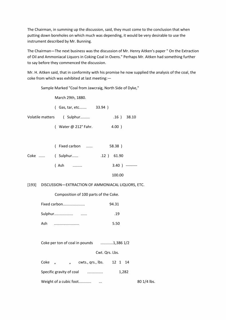
The Chairman, in summing up the discussion, said, they must come to the conclusion that when
putting down boreholes on which much was depending, it would be very desirable to use the
instrument described by Mr. Bunning.
The Chairman—The next business was the discussion of Mr. Henry Aitken's paper " On the Extraction
of Oil and Ammoniacal Liquors in Coking Coal in Ovens." Perhaps Mr. Aitken had something further
to say before they commenced the discussion.
Mr. H. Aitken said, that in conformity with his promise he now supplied the analysis of the coal, the
coke from which was exhibited at last meeting:—
Sample Marked "Coal from Jawcraig, North Side of Dyke,"
March 29th, 1880.
( Gas, tar, etc....... 33.94 )
Volatile matters ( Sulphur......... .16 ) 38.10
( Water @ 212° Fahr. 4.00 )
( Fixed carbon ...... 58.38 )
Coke ...... ( Sulphur...... .12 ) 61.90
( Ash ......... 3.40 ) ---------
100.00
[193] DISCUSSION—EXTRACTION OF AMMONIACAL LIQUORS, ETC.
Composition of 100 parts of the Coke.
Fixed carbon..................... 94.31
Sulphur.................. ...... .19
Ash ........................ 5.50
Coke per ton of coal in pounds ............1,386 1/2
Cwt. Qrs. Lbs.
Coke „ „ cwts., qrs., lbs. 12 1 14
Specific gravity of coal ............... 1,282
Weight of a cubic foot............ ... 80 1/4 lbs.

(Signed) Robt. McAlley.
It may not be out of place to observe that no analysis of coal gives any idea as to whether it is a
coking coal or not, and he did not know any method of analyzing that would show this. The only plan
seems to be to test whether it does coke. These remarks apply to coals containing over 20 per cent,
of volatile matter.
Since the last meeting a gas pump has been put on as an exhauster to draw the gases from the
bottom of the oven in place of the steam jet, and a bubble-washer has been added to assist in the
extraction of the ammonia. A good many charges of coal of four tons four cwts. have been worked
off (oven 10 feet 3 inches dia.) in from 32 to 36 hours, the yield of dry coke being 65.77 per cent.,
that of oil about 8 1/2 gallons per ton of coal, specific gravity 1,000, and the yield of ammoniacal
water about 20 gallons of water, two Twaddel. The coke made was, no doubt owing to the high heat,
in somewhat smaller pieces, but it was harder coke than any produced from ground or small coal.
The analysis of the coal used is as follows:—
Analysis of Binniehill Splint Coal, by Robert McAlley, Chemist,
Falkirk, 27th October, 1879.
Volatile matters .................. 28.83
Fixed carbon..................... 64.20
Ash ........................ 4.50
Sulphur........................ .27
Moisture at 212° Fahr................ 2.20
---------
100.00
----------
Heating power ... ... 8.98
Volatile matters present ... 31.17
Coke per cent. ... ... ... 68.83
Coke per ton in pounds ... 1,541 3/4 lbs.
Cwt. Qrs. Lbs.
Coke „ cwts., qrs., lbs. 13 3 2
Ash per cent, of coke ... 6.53

[194] DISCUSSION—EXTRACTION OF AMMONIACAL LIQUORS, ETC.
The yield of coke here given is 68.83 per cent. The usual yield as per previous analyses of this coal is
66.52 per cent.
In coking this coal in the ordinary 10 feet 3 inch diameter bee-hive ovens the usual time taken with a
three tons four cwts. charge is 80 hours. The time taken with this oven with charges of four tons four
cwts. was from 32 to 36 hours, thus doing the work in one-third the time taken by the ordinary oven.
No charges have as yet been worked off with only three tons four cwts., but it will not take much
more than 24 hours to complete the coking of such a charge.
Mr. Aitken said further in reply to Mr. Hedley and the Chairman, that the coke was harder by his
process than by the ordinary ovens, and retained its silvery appearance. All that was required was a
fan or pump to exhaust the gases, and condensers to cool them to the temperature of the
atmosphere. The ordinary arrangements in use at gas works to absorb the ammonia would do, and
it could, if made large enough, be applied to a row of ovens. He thought the advantage of the
arrangement was, that by its use, coke could be made that was suitable for all purposes, and at the
same time the whole of the oil or tar ammonia would be separated, whereas in all the systems of
coking that he had ever seen, by which it was attempted to get either ammonia or tar during the
process of coking, the coke had been deteriorated and rendered unfit for sale. Mr. D. P. Morison
asked Mr. Aitken if he could give any idea of the saving per ton of coke effected by his process, as
this would facilitate the consideration of the subject on economical grounds. He could easily
understand that if the ammonia and other products of distillation could be taken off and utilized, it
must be a matter of very great moment indeed, provided it was not accompanied by too expensive
machinery, and if Mr. Aitken could give them any information on that subject it would help them to
consider the question usefully.
Mr. Aitken said, he was hardly in a position to answer Mr. Morison, but there was another point
which possibly he should have attended to before, and that was, that in making the coke and taking
off the gases, they largely increased the yield, and invariably obtained within two or three per cent,
of the theoretical result. This was not done with any beehive oven that he had ever seen. The value
of the oil obtained was over threepence a gallon, and as they had been getting eight to nine gallons
per ton of coke, that was about two shillings a ton gained in this way alone, and they had the value
of the ammoniacal water over this.
Mr. Breckon said, that still left them rather in doubt as to the gain per ton of coke, after the expense
and every other disadvantage had been
[195] DISCUSSION—EXTRACTION OF AMMONIACAL LIQUORS, ETC.
taken into account. Now, if a gain of something like a shilling a ton in the use of this arrangement
could be obtained without deteriorating the quality of the coke, that would be at once a strong
incentive to take up the invention and proceed with it as vigorously as possible. With regard to the
percentage of coke obtained (between 53 and 54 per cent.), he thought there were gentlemen
present who were aware that coke ovens had been in use for many years in the county of Durham
that had constantly yielded from 60 to 66 per cent, of good marketable coke, therefore the system
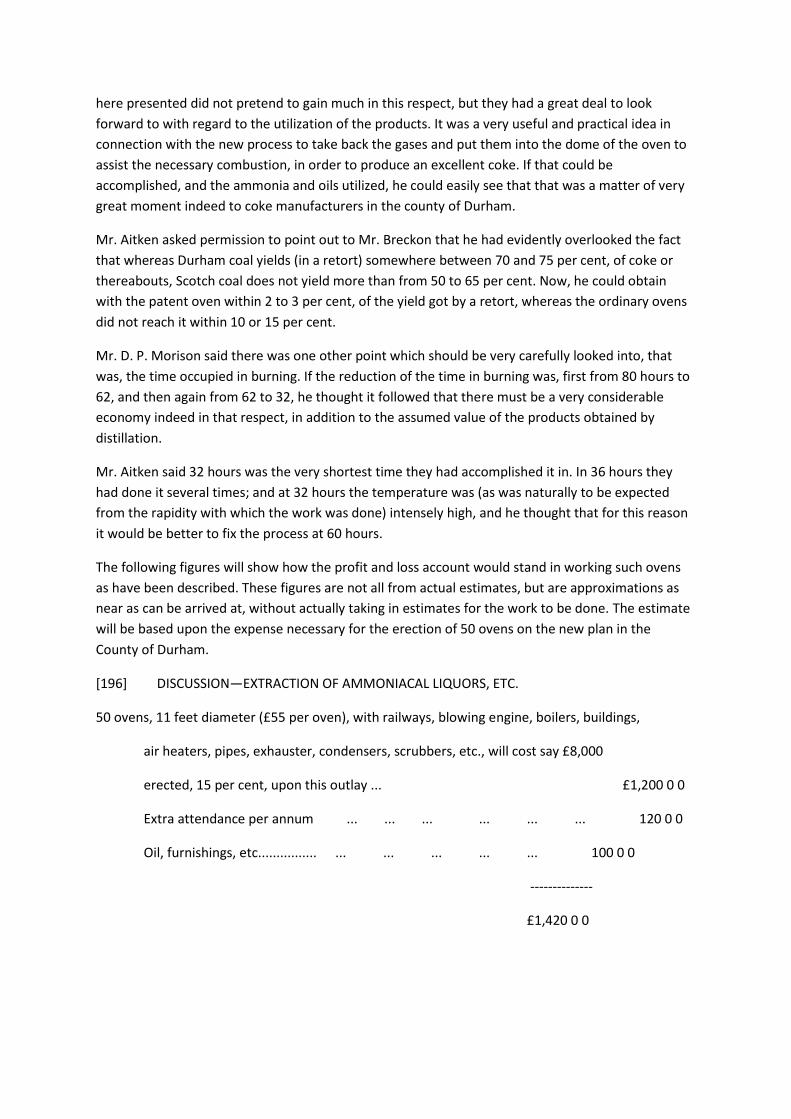
here presented did not pretend to gain much in this respect, but they had a great deal to look
forward to with regard to the utilization of the products. It was a very useful and practical idea in
connection with the new process to take back the gases and put them into the dome of the oven to
assist the necessary combustion, in order to produce an excellent coke. If that could be
accomplished, and the ammonia and oils utilized, he could easily see that that was a matter of very
great moment indeed to coke manufacturers in the county of Durham.
Mr. Aitken asked permission to point out to Mr. Breckon that he had evidently overlooked the fact
that whereas Durham coal yields (in a retort) somewhere between 70 and 75 per cent, of coke or
thereabouts, Scotch coal does not yield more than from 50 to 65 per cent. Now, he could obtain
with the patent oven within 2 to 3 per cent, of the yield got by a retort, whereas the ordinary ovens
did not reach it within 10 or 15 per cent.
Mr. D. P. Morison said there was one other point which should be very carefully looked into, that
was, the time occupied in burning. If the reduction of the time in burning was, first from 80 hours to
62, and then again from 62 to 32, he thought it followed that there must be a very considerable
economy indeed in that respect, in addition to the assumed value of the products obtained by
distillation.
Mr. Aitken said 32 hours was the very shortest time they had accomplished it in. In 36 hours they
had done it several times; and at 32 hours the temperature was (as was naturally to be expected
from the rapidity with which the work was done) intensely high, and he thought that for this reason
it would be better to fix the process at 60 hours.
The following figures will show how the profit and loss account would stand in working such ovens
as have been described. These figures are not all from actual estimates, but are approximations as
near as can be arrived at, without actually taking in estimates for the work to be done. The estimate
will be based upon the expense necessary for the erection of 50 ovens on the new plan in the
County of Durham.
[196] DISCUSSION—EXTRACTION OF AMMONIACAL LIQUORS, ETC.
50 ovens, 11 feet diameter (£55 per oven), with railways, blowing engine, boilers, buildings,
air heaters, pipes, exhauster, condensers, scrubbers, etc., will cost say £8,000
erected, 15 per cent, upon this outlay ... £1,200 0 0
Extra attendance per annum ... ... ... ... ... ... 120 0 0
Oil, furnishings, etc................ ... ... ... ... ... 100 0 0
--------------
£1,420 0 0
These 50 ovens will coke 3 tons of coal each per 24 hours, or 150 tons per day, and they will produce
9 gallons of oil per ton, 1,350 gallons for which 3d. per gallon, without barrels, have been offered,
taking however, for safety 2 1/2d. per gallon.
This gives ... ... ... ... ... ... ... £14 1 3
The ammonia water is probably worth 1s. 3d. to
1s. 6d. per ton of coal coked, but say 1s. per ton ... ... ... 7 10 0
_________
Together ... ... ... ... ... ... ... £21 11 3
Which, multiplied by say 280 working days in the year, gives... ... ... 6,037 10
0
To this has to be added the increased yield of coke which is estimated at from
8 per cent, to 15 per cent., say however, that 70 per cent, is got in place of 65
per cent., the extra coke thus got will be 2,100 tons at 10s. per ton ... ... 1,050 0
0
_________
£7,087 10 0
It is to be kept in mind that ovens worked so rapidly, and at such a high temperature will require
more repair, but the above would leave ample margin.
Further, the only coals which have been used are Scotch, other coals would require to be tested
before adopting the process elsewhere. It is also to be kept in view that for the production of the
amount of coke which the above 50 ovens would make, there would be required about 125 ordinary
ovens. These would cost at £55 each, £6,875, so that the extra outlay for the new ovens, with all the
necessary appliances, would only be £1,200 more.
The Chairman did not think there was anything more to be said on the subject. He begged to
propose a vote of thanks to Mr. Aitken for
[197] DISCUSSION—EXTRACTION OF AMMONIACAL LIQUORS, ETC.
having kindly come all the way from Falkirk to resume the discussion of his paper. He felt sure that if
such results as Mr. Aitken stated had been attained with his experiments in Scotland, and it could be
carried out successfully in the same way here, it would speedily be applied.
Mr. Breckon seconded the resolution, which was unanimously carried, and the meeting terminated.
[198 blank page]
[199] PROCEEDINGS.
PROCEEDINGS.
GENERAL MEETING, SATURDAY, MAY 1st, 1880, IN THE WOOD MEMORIAL HALL,
NEWCASTLE-UPON-TYNE.
G. C. GREEN WELL, Esq., President, in the Chair.
The Secretary read the minutes of the last meeting and reported the proceedings of the Council.
The following paper " On Safety-Hooks," by Mr. William Logan, was then read:—
[200 blank page]
[201] SAFETY-HOOKS.
SAFETY-HOOKS.
By WILLIAM LOGAN.
In the month of December last year a letter was addressed by the various Inspectors of Mines, at the
instigation of Her Majesty's Secretary of State, to every manager of mines, drawing their " attention
to the inventions for disconnecting in case of overwinding, such as are now in successful use at many
collieries," and expressing a hope that, " if such appliances are not already attached where they are
applicable at your mines, you will kindly give the subject your earnest consideration with the view of
having them applied."
From this it would appear that the Inspectors of Mines are now unanimous in recommending the
adoption of safety-hooks, and it may possibly be that in a short time they will ask for means to
enforce their adoption. It is in view of this that the writer has been induced to prepare a paper with
the hope of elucidating the opinion of the members of this Institute on the subject.
The Inspectors of Mines have not always been unanimous on the subject, as the late Mr. John
Hedley, in his report for 1863, says:— " They cause a false feeling of security, and the ropes, chains,
and other portions of the winding tackle are neglected through the reliance placed on the so-called '
safety-apparatus.' " And Mr. Ralph Moore, in his report for 1878, referring to an accident from
overwinding, says:— " Notwithstanding this accident, I am not prepared to advise the adoption of
any of the various so-called ' safety-hooks.' "
The other Inspectors, when commenting on accidents from overwinding, have, however, from time
to time recommended their adoption.
For over twenty years safety-hooks in some form or other have been before the public, and every
inventor of a safety-hook claims that by the use of his hook lives have been saved; but as no reliable
data exist as to the number of lives saved except that published by the inventors themselves, and as
such data must be taken cum grano salis, the writer refrains from giving the numbers.
There are also no accurate data as to the number of overwinds that

[202] SAFETY-HOOKS.
take place, for although an act of overwinding may cause great destruction of property, it is only
when an accident occurs fatal to human life that the fact is recorded, and, up to the end of 1872,
only at those mines which were under Government inspection. Since 1872 the field of inspection has
been enlarged, and there is now a full and reliable record. The Mines Inspectors' reports, beginning
at 1855, have been carefully examined, and they show the following number of lives lost by
overwinding :—
No. of Lives Lost.
1855 to 1859 inclusive ..................... 47
1860 to 1864 „ ..................... 35
1865 to 1869 „ ..................... 36
1870 to 1874 „ ..................... 28
1875 to 1879 „ ..................... 32
__
Total ... ......... ...... 178
And these may be classified as follows :—
No. of
Causes. Lives Lost. Percentage.
1. Defect of engine, throttle valve sticking, crank pin
breaking, insufficient brake power, etc ... ... 13 7.30
2. Defect of indicator not showing position of load ... 11 6.18
3. Attention of engineman withdrawn from engine by
persons in engine-house ... ... ... ... 10 5.62
4. Incompetent engineman ... ... ... ... 6 3.37
5. Engine reversed and cage drawn wrong way ... 22 12.36
6. Fault of engineman omitting to stop load at proper
place .................. 110 61.80
7. Collapse of safety-hook, or failing to act properly 4 2.25

8. Cage lowered into sump and occupants drowned ... 2 1.12
___ ____
178 100.00
Thus, omitting No. 8, 98.88 per cent, of the lives lost would have been saved by the adoption of
efficient safety-hooks and other appliances.
Previous to the Mines Inspection Act of 1872, coal was the only mineral of which an accurate
account was kept, and the writer has only been able to obtain reliable returns commencing in 1864,
and these show the following results :—
Tons of Coals Lives Lost by Causes
Worked. previously Enumerated.
From 1864 to 1872 inclusive ...... 966,119,982 60
Or one life lost for every 16,109,999 tons of coal worked.
[203] SAFETY-HOOKS.
The details from 1872 are much more comprehensive, and may be given fully as follows, embracing
as they do the whole of the United Kingdom:—
[table]
So that from the causes previously enumerated, there is one life lost for every 23,373,989 tons of
mineral raised, and one life lost for every 64,451 persons employed.
It will, of course, occur to every one that a portion of this mineral is not raised by vertical shafts, but
is produced by adits, and that the tons of mineral raised per life lost is greater than the actual
quantity; but it is also known that the quantity of mineral raised otherwise than by vertical shafts is
small compared with the whole quantity, and the writer ventures to state the approximate actual
quantity as one life lost for every 20,000,000 tons of mineral raised during the last seven years.
The number of windings that take place to lower and raise the persons employed underground can
also only be arrived at approximately, and the writer assumes an average of six persons descending
and ascending in one cage (and this he considers a high average), so as to allow for the number of
persons who do not descend or ascend in cages where the mineral is not got by vertical shafts, this
gives 64,451 persons divided by six, and this doubled for the descent and ascent, and multiplied by
250 working days a year, makes one life lost for about every 5,500,000 windings of persons
employed underground during the last seven years.
[204] SAFETY-HOOKS.
For the purpose of preventing the loss of life, destruction of property, stoppage of work, etc.,
numerous inventions have been brought to the notice of the public, and, for the purpose of inviting
discussion on the several appliances, the writer will proceed to describe them in detail.
BRYHAM'S HOOK.
This hook has now been in use for upwards of twenty years, and was the invention of Mr. John
Bryham, of Rosebridge Colliery, Wigan. It belongs to the class of simple detaching hooks, and its
action will be seen in Plate XXXIV. (Figs. 1, 2, and 3), which represents the hook in front and side
views; A A represent two wrought iron plates, forged with slot B, to receive the shackle C, as shown
in Fig. 2, to which is attached the cage ; D is a wrought iron disengaging plate forged with the slot E,
as shown in dotted lines, and fixed between the plates A A ; it is kept in its working position by a
small brass pin F; G is a wrought iron plate of suitable size, fixed in the head gear framing, with the
rope working through it, and consequently when the cage is raised too high, the hook being
attached to the rope is drawn through a circular hole in the plate of such a diameter as not to allow
of the hook passing through it without first shearing the brass pin F, pressing in the plate D, and
removing the shackle with its load from its working position into the slot B, and thus disconnecting
it. To prevent the cage from falling down the shaft after detachment, catches are fixed in the guide
rods and so arranged that the cage in ascending raises the catches, and immediately it has passed
them they fall into their original position and receive the cage after detachment from the rope and
hook.
KNOWLES'S HOOK:
The invention of Mr. Israel Knowles, of the Ince Hall Collieries, is also a simple detaching hook, and
its action will be seen by reference to Plate XXXV. Fig. 1 is a front view, and Fig. 2 a side view of the
hook when attached to the rope and cage; Fig. 3, shows the hook after detachment has taken place.
As in Bryham's arrangement a wrought iron plate with a circular hole is fixed to beams in the head
gear to cause detachment.
The rope is attached to the pin A; B B are wrought iron plates forged with a slot C; D is a wrought
iron disengaging plate kept in position by the copper pin E, and disengagement is effected by the
wing of the plate D being unable to pass through the circular hole of the plate fixed in the head gear
without shearing the copper pin E, forcing the pin F into the
[205] SAFETY-HOOKS.
slot C, and so releasing the rope. Safety-catches or keeps are placed in the guide rods to receive
the cage after detachment.
Having described two hooks, which are simple detaching hooks, the writer will now proceed to
describe hooks which aim at not only being detaching hooks but which are so constructed that after
the rope is released they suspend the cage without the aid of catches or keeps.
KING'S HOOK:
The invention of Mr. King, of Pinxton, Derbyshire. Plate XXXVI., Fig. 1 and 2 represent a front and a
side view of the hook in working order; it is self-detaching and self-suspending, not only detaching
the rope but suspending itself at the moment of detachment with the cage attached. Fig. 3
represents the hook when detached and suspended on the catch plate, which is securely bolted on
to two strong timber or girder beams in the head gear. The catch plate has a circular hole through
which the rope runs.
The hook consists of a framework of two outer plates, A A, between which are fixed two inner
plates, B B, so as to oscillate about a strong pin C, which goes completely through all the plates; the
four plates being for the greater part of their length of exactly the same width.
The winding rope is attached to the top shackle F, and the cage chains to the bottom shackle J at the
lower end of frame A A, which is made of uniform width throughout, with the exception of the
projections KK at the bottom, so that it easily fits, and can freely enter the ring in the catch plate, but
not pass quite through it.
Each of the plates, B B, is a fac-simile of the other, having the top part G G shaped as a hook, which
entirely overlaps and takes a firm hold of the shackle pin L, the lower part being feathered out on
one side D D. It will thus be seen that when set in the framework in opposite directions on the pin C
and shut together, they form a double hook at the top, and the pin has no tendency to slip out
owing to the slight curve of each jaw.
As an additional safeguard a copper pin H, three-eighths of an inch diameter, goes through all the
four plates.
In ordinary work the weight of the load carried by the hook is communicated to the rope by the
bottom shackle J and pin P through the outer plates or framework A A, the pin C and the hooks G G
of the inner plates B B.
In case of overwinding the hook passes up through the circular hole of the catch plate fixed in the
head gear; the two wings D D of the inside
[206] SAFETY-HOOKS.
plates which project beyond the framework are forced inwards by coming in contact with the catch
plate O, the pin H being sheared into four parts, and the jaws at the top gradually separated from
each other until the shackle pin L can escape between the inner points. The rest of the motion is
assisted by the escape of the pin of the rope shackle between the inclined noses of the jaws G G,
while the hook and load are left hanging on the catch plate supported by the two catches E E, which
were forced outside the framework by the same action which released the rope.
KING AND HUMBLE'S HOOK.
King's hook, as improved by Mr. Stephen Humble, of Derby. This hook is represented by Plate
XXXVII., Figs. 1, 2, and 3, and in construction and action is almost identical with King's hook
previously described, except in the details which will be fully noticed.
Fig. 1 represents a front, and Fig. 2 a side view of the hook as in actual working order. It is a self-
detaching and self-suspending hook.
Fig. 3 represents it when detached and suspended on the catch plate.
The hook consists of four plates, viz :—Two outer A A and two inner D D, which oscillate about a
strong pin J.
The difference between this hook and the one previously described is, that the projecting wings are
dispensed with, and a collar B is substituted, which goes completely round the plates, and is held in
position by two copper pins, N N. In the collar is placed a loose pin E, which passes completely
through both the collar B and the four plates of the hook. In each of the outer plates there is a
vertical slot I, and in the inner plates grooved slots F F.
In ordinary work the weight of the load carried by the hook is communicated to the rope by the
bottom shackle O, pin P, side straps Q, the centre pin J, and the hooks K K of the inner plates D D.
When an overwind occurs, the hook passes into the ring or catch plate, and the collar B in which is
the pin E, comes in contact with the catch plate C, and as the hook is still drawn upwards, the natural
result is that the collar is pressed down, shearing the copper pins N N; and the inside plates D D,
being actuated by the pin E in slots F F, are forced open, releasing the rope shackle, and the hook
with its load is left suspended on the catch plate, by the two catches M M of the inside plates which
are sufficiently strong to hold the load attached to the hook.
In King's hook (Plate XXXVI.) it will be noticed there is just sufficient space for the catch plate to rest
between the wings D D, and catches E E, and in King and Humble's hook between the collar B and
catches
[207] SAFETY-HOOKS.
M M; consequently it is believed to be impossible for either hook to detach itself until drawn
sufficiently far through the circular hole in the catch plate, and this is effected either by a quick or
slow overwind.
Another point of importance is that the hooks being overhung, that is, the pins C (Plate XXXVI.) and J
(Plate XXXVII.) being above the catches E E and M M (the faces of which when first emerging from
the frame are inclined upwards towards the centre of the hook) the moment the catches gain the
slightest hold upon the catch plate, the safe suspension is practically accomplished; for the weight of
the load will then tend to force the catches out to their full extent, and there is not any chance of
the hooks again closing. Until this point in the action of the hook is reached, their tendency is not to
open, but to keep shut, on account of the gradual curve in the inner plates clutching the rope
shackle pin L.
The other points claimed in these hooks are the gradual and simple nature of their motion, and the
great simplicity both of the hooks and catch plates, while the catching points E E and M M, owing to
their vertical depth are exceedingly strong.
ORMEROD'S HOOK:
The invention of Mr. Edward Ormerod, of Manchester, first patented in 1867, but since improved by
the lengthening of the middle plate to facilitate re-attachment.
This hook as will be seen by Plate XXXVIII. also belongs to the class of plate hooks, and the inventor
claims for it that the strain is not transmitted from one plate to another, causing a shearing strain on
the pins ; but if perfectly made, the strain is through all the plates from end to end.

It is also a detaching and suspending hook, and instead of using a catch plate on which to support
the load after detachment takes place, a cylinder is used.
Fig. 1 is a front view of the hook. Fig. 2 is a side view, and Fig. 3 represents the position it assumes
after detachment of the rope and suspension of the load with the hook on the cylinder.
It will be seen that the hook is formed of three plates, and when in ordinary use, as in Fig 1, is wider
at the bottom than the top; but in the event of overwinding the hook is drawn into the bell-mouthed
cylinder F F (Fig 3), and the wide parts of the hook at H H, coming in contact with the inner side of
the cylinder, are pressed inward, while the top parts are pressed outward, allowing the projections
to catch over the top
[208] SAFETY-HOOKS.
of the cylinder. At the same time the rope shackle A is forced out of its seat and allowed to go free,
while the bottom shackle B drops into the slot D and locks the hook firmly in its position.
To prevent the plates being disarranged in ordinary working, a copper pin P is inserted through the
plates, which keeps them in position and is sheared through as the hook passes into the cylinder.
To facilitate the lowering of the cage after detachment, the shackle A is attached to the ear of the
middle plate as shown in Fig. 4. On removing the pin C and slightly winding the rope, the middle
plate—having a slotted hole for the pin—is elevated into the position shown, and allows the hook to
pass down through the cylinder; the cage is safely lowered on to the keeps and re-attachment takes
place.
THE GRANGE HOOK.
This hook is of recent construction, and is being manufactured by the Grange Iron Company,
Durham. It consists of three plates planed true on the inner sides (Plate XXXIX.); the middle plate A
to which the lifting shackle B is attached, has two projections to prevent the hook being drawn
through the plate, and the distance between the projections and those on the two outer plates is
the least possible, so as to give a minimum amount of fall when detached. The three plates are held
together by the centre bolt C, to the projecting ends of which a double hook or claw is attached to
lift the hook and cage after detachment, and refix the rope shackle D. The two outer plates are held
in position by the copper rivet E.
Figs. 1, 2, and 3, represent a seven ton hook. Fig. 1 shows the hook ready for detaching, and Fig. 3
after detachment. The bolt F during detachment drops down into a groove and prevents the plates
re-adjusting themselves by the shock, and falling through the retaining plate G.
WALKER'S HOOK.
This hook belongs to a different class to those previously described, and is also detaching and
suspending; it was invented by Mr. William Walker, of Saltburn-by-the-Sea, and has been in use
since 1871.
Plate XL., Fig. 1, represents the hook closed and attached to the rope, the cage being attached to the
bottom link B.
Fig. 2 shows the hook open and anchored on the cylinder C after detachment has taken place.
The lifting rope is attached to the shackle A, and the load to the connecting link B.
[209] SAFETY-HOOKS.
The supporting ring C (through which the rope is constantly working) is a fixture in a baulk of timber,
or iron girder, at the pit top.
The hook consists of a pair of jaws, D D, working on a centre pin, E, in such a manner that the weight
of the load has a tendency to open the upper limbs, which clip the strong centre pin of the shackle A.
The upper limbs are formed externally with jaw hooks, F F. The jaws are kept together, and made to
retain the shackle pin by means of the clamp H, which is held in position by the copper pins I I.
In case of overwinding, the jaw hooks (held together by the clamp) pass freely into the ring C, but
the projections K K of the clamp coming into contact with the bottom flange of the ring, hold the
clamp stationary, while the jaws are being pulled through, the result being that the pins I I are
sheared off, and the jaw hooks released from the restraint of the clamp. The internal diameter of the
ring being the same as the width across the jaw hooks, F F, the rope remains secure until the jaw
hooks reach the top of the ring, when, by the action of the weight of the load, they are forced open,
and so hook on to the top of the supporting ring C, as shown, the rope passing harmlessly over the
pulley.
The recess O, in the ring C, is intended to meet an imaginary case that experiment shows to be
almost impossible, namely, that if the engine is reversed after the pins I I are cut, and before the
hooks reach the top of the ring, the jaws will then hook into the recess, and the load remain
suspended in perfect safety.
It will be observed that the upper edge of the ring C is curved to match the sweep of the jaw hooks
when opening. By this arrangement all shock is avoided.
The size of the pin of the shackle A is so proportioned that, in leaving the jaw hooks, they are
opened by it on to the full hold of the ring, and the clamp H at the same time coming down on to the
lower limbs, locks the hook securely on to the ring.
WALKER'S IMPROVED HOOK.
Mr. Walker has recently improved his hook in the manner shown in Figs. 1 and 2, Plate XLI.
Instead of the cylinder, a catch plate A is substituted, and four copper pins B B, B' B' are used. A
square hole is cut in the clamp C, and the clamp kept in position by a tongue and the two upper
copper pins B B, and detachment cannot take place until not only the two upper copper pins B B are
sheared, but also the two lower copper pins B' B'. The clamp C is forced down by coming against the
catch plate, expanding the upper jaws and
[210] SAFETY-HOOKS.
pressing in the lower limbs. On the inside of the clamp C, and on the sides which move down the
outer edges of the lower limbs, feathers of brass, E E, are securely fixed, which facilitate the
movement of the clamp downwards, and are so shaped that when the clamp C is in the position
shown on Fig. 4, it locks the hook and keeps the jaws properly expanded. To prevent too much
expansion of the suspending jaws, a stud D is fixed to the inner side of one of the lower limbs.
It will also be observed that in the original hook the clamp was not prevented from coming down on
to the lower shackles, but in the improved hook this is entirely prevented.
The outer shape of the clamp is much better in the improved hook, and the projections K K in the
original clamp are done away with.
RAMSEY AND FISHER'S HOOK,
The invention of Mr. Ramsey, of Castle Eden Colliery, in the county of Durham, is also a detaching
and suspending hook. Patented in 1876, it has not been long before the public; but as now
manufactured, it merits, from its peculiar construction, careful notice.
Two independent jaws, A A, Plate XLII, are contained in a box of great strength; they are separately
hung on the bolts BB, and separately actuated; and in ordinary working are kept firmly in position by
means of the two keys C C, shown projecting slightly at the sides of the box. The keys rest upon two
copper rivets, D D; but they are so constructed as to exert no pressure upon the copper rivets until
an overwind takes place. When the hook passes up into the strong cast-iron ring E fixed in the head
gear, the two keys come simultaneously into contact with the conical lower end of the ring, are
pressed downwards, and by cutting the copper rivets, and pressing the lower ends of the jaws
together, they open the top ends so as to catch upon the ring, and release the shackle and rope.
As the rope disengages it draws up between the jaws a wedge F, rivetted by a small copper rivet to
the links G, on the top shackle. The act of cutting this rivet is sufficient to firmly fix the wedge
between the two jaws, securely locking them on to the ring and making it absolutely certain that the
hook catches the ring properly, and perfectly impossible to shake it off again by any amount of
jerking and shaking.
The tops of the jaws are kept extra large, and a hole bored in each, as shown. After an overwind it is
only the work of a few minutes to couple a shackle on to each jaw, knock down the wedge, and, by
tightening the rope with the engine, close the jaws and lower the cage safely on to the
[211] SAFETY-HOOKS.
keeps. By placing a little tallow or grease round the edge of the box the working parts are effectually
protected from all damp and kept in perfect order, ready for action.
Each jaw being separately actuated, and it being necessary that both keys should be struck and both
rivets cut before disengagement takes place, it may safely be said to be impossible to disengage the
load in ordinary working. The fall back is in no case more than one inch, and partial overwind cannot
take place to disengage the hook, as the jaws must be in position to grip the ring before the rivets
are cut.
BOOTH AND SUGDEN'S HOOK.
This hook was patented so late as November, 1879, by Messrs. Booth and Sugden, of Hollinwood,
near Manchester, and the writer has been supplied by Mr. Thomas Sugden with the following
particulars. A drawing of the hook is given in Plate XLIII, Figs. 1, 2, and 3:—
A box is secured by the usual D links to the socketing or capping at the bottom of the winding rope,
and to the cage chain in this box the hook or bar to be released is secured, the box being shaped out
to receive the same. In the hook there is a hole shaped out in which a stud A is inserted ; this stud
carries the load, and has a bearing on each side of the box, which is prepared to receive it. Below the
hole a wing or wedge-shaped projection is fixed upon, or rather shaped upon, each side of the hook,
the wings being thickest at the lower end, and tapering upwards.
Immediately opposite the bearing stud, and in the same line with it, is fixed another stud B, which is
the forcing stud.
Both studs are kept in position by copper pins screwed into the box, and both are chamfered off on
the lower edge so as to form an inverted V when together.
The end of the forcing stud B projects outside the box while the whole of the bearing stud is
concealed within the box.
Near the pulley is fixed a beam or beams, to which an iron casting, through which the rope passes, is
secured. The casting is constructed to receive the box, and to detach the rope when the box is drawn
through the aperture which is constructed on one side with a tapered slot, having its deepest part at
the lowest edge, and on the other side with a corresponding projection. This is so arranged that the
box in passing through the aperture causes the projecting part of the forcing stud B to come into
contact with the bottom of the slot, the forcing stud B being then pushed inwards into contact with
the bearing stud A, which is thus forced outwards, when the box has been drawn through the
aperture sufficiently
[212] SAFETY-HOOKS.
far, that the forcing stud is clear of the top, both the forcing stud and the hearing stud at their inside
ends form together an inverted V exactly opposite to the hook. The hook being slightly narrower
than the bottom of the V, readily enters. The ends of the studs are now just clear above the
aperture; the box is held at this point by projections which prevent it from going through the
aperture, so that the hook is drawn through the V, forcing the studs outwards to a distance sufficient
to project so far over the sides of the aperture as to hold the cage securely in position.
After disconnection has taken place, the rope can readily be connected by placing the hook in the
box and forcing the studs back, so that it will again descend through the aperture. This is done by
means of screws placed at the top of the aperture for that purpose. The lowering of the box through
the aperture forces back the studs to their original positions, and winding can then proceed as usual.
If the rope comes to a position of rest when the box is in the aperture, and afterwards be made to
descend, in descending the projection in the aperture forces back the studs to their working
position, so that the hook quits the aperture in exactly the same condition as it enters, thus
obviating accidents from what is known as partial overwinding.

This hook is only applicable to shafts in which guides are used, and cannot be applied to a sinking pit.
FORSTER AND ROBINSON'S HOOKS.
The invention of Messrs. Forster and Robinson, of the Water Works, Newcastle-upon-Tyne.
The writer has carefully examined a model of one of their hooks, and a drawing of another, and
hopes to be able to furnish drawings and details at a future time.
The writer might have added, had he thought it would serve any good purpose, descriptions and
drawings of other hooks which have been brought under his notice ;* but as they did not possess
any feature of special interest, and were in his opinion defective in design, he has not done so, and
he proposes now to offer a few remarks on the hooks noticed.
Bryham and Knowles's hooks belong to the class of simple detaching hooks, the principal difference
being that in Bryham's the hook goes with the rope, and in Knowles's it is left on the cage top. They
are both good
* Other hooks have been illustrated in Vol. XIX., Appendix I., of the Institute Transactions.
[213] SAFETY-HOOKS.
hooks, and with the aid of safety-catches in the receiving rods they have done good service, and
point to what a large number of people consider as a necessity, even along with detaching and
suspending hooks, namely, receiving keeps, or suspenders, in the head gear, and this is especially
necessary in the case of a very rapid overwind. When in use along with a detaching and suspending
hook, they are designed to meet the possibility of either a collapse of the hook or the breaking of the
cage chains by the sudden shock to the hook and chains, caused by the momentum which the cage
has acquired by its upward velocity, carrying the cage upwards, after the hook has done its duty and
released the rope; and a fear that in falling back the chains or hook, or some part of them, might
give way. To take the shock off the cage, chains, and hook, Mr. Stephen Humble has invented what
he calls a " Patent Safety-Cage Suspender," which meets all the requirements of the case.
King's and Ormerod's hooks have been before the public for a considerable time, and have answered
the purpose for which they were intended very well; but the writer thinks that King and Humble's
hook is superior to either.
The " Grange hook," which also belongs to the same class as King's and Ormerod's, is of recent
construction, and has not yet been severely tested in actual practice, but considering the careful way
in which it has been proportioned and constructed, and the great strength of plate over the top
shackle bolt, it cannot fail to take a good position.
Walker's original hook has now been before the public for some years; but the writer thinks his
improved hook a considerable advance upon it, not only from the improved locking, the absence of
wings in the clamp, and the preventing of the clamp falling upon the lower shackles, but as being
generally a better hook in every way.
Ramsey and Fisher's is especially good in design, and although apparently complicated, is
exceedingly simple and sure in its action.
Objection has been taken to the use of safety-hooks on the ground that they may make the
engineman careless, but this is not a valid reason. It ought, however, to be a rule that whether
safety-hooks are applied or not, the engineman who makes an overwind, except when testing the
hooks under direction, should be fined or dismissed.
Another objection to their use is, that the distance between the flat sheets and pullies is lessened by
the fixing of baulks or girders to carry the detaching apparatus, and that it is probable, had there not
been such apparatus, the engineman who started his engine the wrong way would have had a
greater distance in which to correct his mistake. The number
[214] DISCUSSION—SAFETY-HOOKS.
of lives lost from this cause, as has been already shown, is exceedingly-small, and these would have
been saved had safety-hooks been applied.
There is also another objection made on the ground that something might fall down the shaft when
the load was running and cause detachment. This, although possible, is met by the fact that hooks
are now made which have such very slight projections that it is very remotely probable they would
be struck; and further, even if one side was struck, it would not cause entire detachment.
Safety-hooks are only a portion of the colliery machinery, which ought at the same time as the ropes
and chains to be carefully examined, and if this is done, there is no more risk in using a safety-hook
than in using an ordinary shackle, and by their use many lives and much valuable property will be
saved.
There is one part of the inquiry which the writer has left out for want of reliable information, and
that is the amount of dead pull necessary to detach any of the safety-hooks described, and as he
thinks it a matter of importance he trusts that the subject will be taken up by some other member or
a small committee appointed by the Institute.
The points to be ascertained are—
1. The dead pull necessary to detach the hook when new.
2. The dead pull necessary to detach the hook after it has been left in a condition to represent
working in a wet shaft for a definite period.
3. The dead pull necessary to detach the hook after it has been left in a condition to represent
working in a hot and humid upcast shaft for a definite period.
In conclusion the writer begs to express his thanks to the various inventors of the hooks described
for the information supplied, and to the Secretary of the Institute for extracts from the Mines
Inspectors' Reports.
The President said, he was sure they were all very much obliged to Mr. Logan for the interesting
address he had given to them upon the important subject of Safety-hooks. He would be very glad to
hear any remarks which any member might have to make. Perhaps a general discussion would be
better postponed until the paper was in the hands of the members.
Mr. D. P. Morison thought the subject which had been brought before them was one of great
importance, and had received full justice at the hands
[215] Discussion—safety-hooks.
of Mr. Logan. That gentleman had evidently taken great pains with the paper, and had gone into
nearly every detail they required on the subject. There were one or two points in the paper which he
would like to comment upon. Mr. Logan mentioned the fact, that out of the whole body of
Government Inspectors, there were only two who at all objected to the use of safety-hooks. One of
these (Mr. Hedley) he was sorry to say was not alive, but he believed that Mr. Hedley's opinion was
given before the introduction of safety-hooks as now improved, so that perhaps his opinion might
now have been modified. He thought he was at liberty to say that Mr. Ralph Moore now
recommended safety-hooks in collieries under his control, and it might be said that the whole of the
Inspectors in their reports had shown that some action should be taken by the collieries, and that
the Government also appeared to desire their use. He observed that out of the total loss of life in
the shaft 99 per cent, might have been saved by safety-hooks; and that of itself was a point which
should be brought before the public. He would further remark, that although no particulars are
taken down as to the loss of property which occurs through the absence of safety-hooks, yet he
believed that a great deal of property had been saved by their use.
The President thought there were safety-hooks of a somewhat earlier date than those Mr. Logan
had described. He himself had a small model which had belonged to the late Mr. Matthias Dunn,
which was very old.
Mr. Stephen Humble said, King and Humble's hook had been tested a great many times, yet he
would be most pleased to supply one or two hooks to any colliery in the immediate district for the
purpose of trying them before a committee of the Institute, in the manner which Mr. Logan
suggested, and he hoped that all patentees or makers of hooks would do the same.
Mr. D. P. Morison said, that Mr. Fisher, who was present, but who was not a member of the
Institute, would make exactly the same offer either to a committee or any private colliery which
would like to make the test.
Mr. Lawrence said, that he had applied an hydraulic weighing machine to the hook made at the
Grange Ironworks and found that in drawing the hook through the ring the strain required to shear
the copper rivet, which was half-an-inch in diameter, was 75 cwts. He was not satisfied with the first
experiment, but on repeating the trial the result was so nearly the same that he concluded it
represented pretty accurately the force required to disengage the hook. This, he thought, would
effectually remove the objection of those who thought that accidents might arise by any accidental
strain on the shearing part of the hook. In order to arrive
[216] DISCUSSION—SAFETY-HOOKS.
at data whereby hooks of this make could be properly proportioned, he made a seven-ton hook of
three forged scrap iron plates and sent it to the registered test, and the two outside plates gave way
across the bolt-hole forming the axis, at a strain of 56 tons; he then had one made of forged steel
from the Attwood Steel Works, Wolsingham, the same size in every way as the iron ones. When this
was tested, the wrought iron shackles, which were of the same size as with the iron plates, gave way
at 56 tons. In reply to a question from Mr. Humble, Mr. Lawrence said, that he would be very glad to
give all the dimensions of the hooks and shackles to Mr. Logan, so that he could embody them in his
paper.
Mr. Stephen Humble said, that he also carried out a series of tests at the Government Proving House
at Tipton, for the purpose of ascertaining the best material for making the hooks. He had a six-ton
hook sent there; the shackles were 1 3/4 inches in diameter, and all the pins of the same size. The
plates were one inch thick and made of Bowling iron; another made of Landor Siemen steel; and a
third of best Staffordshire iron. The best Staffordshire plates broke short off through the hook at 21
tons, which very much surprised him, and he instantly discarded the use of Staffordshire plates. The
Landor Siemen steel broke quite suddenly at 45 tons, but the plate was drawn out about one-eighth
of an inch. But with the Bowling iron, that portion of the hook in tension near the pin tore away, at a
strain of 54 tons, sufficiently to allow the shackles to slip away; the outside portion of the hook in
compression did not give way in the slightest degree, consequently the hook was not separated
entirely from the plate, and in consequence of this experiment the hooks were now made entirely of
Bowling iron.
The President—Then Bowling iron is 20 per cent, stronger than Siemen's steel?
Mr. Stephen Humble—So it would appear.
Mr. Lawrence said, that in future he intended to have all the hooks made at the Grange Iron Works,
tested to double the strain they were intended to work under; and the tests he had described had
been made to enable him to proportion all parts of the tackle so as not to give way under eight times
the working strain.
Mr. Stephen Humble said, that this should always be done, and perhaps even a larger margin
provided to allow for the extra strain upon the hook at the moment of detachment, and he read a
certificate from the Superintendent of Lloyds' Proving House, Tipton, showing that the inside plates
of a six-ton hook which he had sent there to be broken to destruction fractured at 54 1/5, tons, and
the pins and shackles bent not quite 1/8 of an
[217] DISCUSSION—SAFETY-HOOKS.
inch, thus proving that the breaking strain of his hooks were made considerably stronger than nine
times the working load. At the Blackwell Colliery an experiment had been made in order to see what
the weight of load would be upon the hook at the moment of detachment. A hydrostatic weighing
machine was suspended from the bottom shackle of the detaching hook to the bull ring of the cage
chains. The cage and load weighed five tons, and a self-registering indicator was placed on the
weighing machine to show what the strain would be in case of overwinding. The engineer was then
told to start and overwind at full speed; detachment took place, and the strain upon the hook
indicated by the weighing machine was 10 tons 10 cwts., or more than double the weight that was in
the load. Objections were sometimes made that hooks were likely to get out of order from rust. He
thought this was a very poor objection, for as every part of the colliery plant should be thoroughly
examined and cleaned from time to time and kept in perfect repair, why should the hook not be
examined and repaired as well ? and he thought that this could be done effectively if they were
taken to pieces and cleaned every two months.

Mr. May said, there was one question which he would like to ask— whether they consider hooks
safe in cases which frequently occur at collieries where different decks had to be loaded, and where
the hook had to go down and lie upon the cage and then be drawn away again, and whether in these
cases there was not a tendency for the hook to come loose in the same way as it might do by
anything falling down the shaft and catching the projecting flange or trigger ?
Mr. Lawrence, in reply, said he believed that nearly every time the cage arrived at the bottom of the
shaft the hook struck the roof of the cage, but he had never heard of any of them having become
injured thereby.
Mr. D. P. Morison said, that Ramsey and Fisher's hook by its box shaped exterior and small and
independent projecting parts, would entirely meet the case put by Mr. May. No shaking or vibration
upon this hook, and no blow of any description whatever, could possibly disengage it. All hooks
which depend upon projecting plates were open to the objection that a blow upon any one of them
had a tendency to shear the copper pin and disengage. Even if the pin was not sheared through, they
had found in the case of the small models which had been exhibited and shown for some time that it
had a tendency to bend, or to become marked in such a way as to become unsafe after a certain
degree of work. He thought, therefore, that the question which had been put
[218] DISCUSSION—SAFETY-HOOKS.
by Mr. May was a very pertinent one indeed; and he trusted that the whole matter would be
investigated either by a committee, or at some colliery where the proprietor might be induced to
take the trouble of testing the different hooks. He would also suggest that any violent test which
the different hooks might have borne should be explained before that committee. He was
informed, and believed it perfectly true, that the hook of Messrs. Ramsey and Fisher had been
tested very severely, and it had been found that the rope, shackles, and everything had given way
except the hook itself. He suggested that the inventors be asked to send in to Mr. Logan the results
as a continuation of his paper. He would further advise that the points which each different
manufacturer claimed should be indicated. Mr. Lawrence, for the Grange Company, pointed out
certain advantages in his; Mr. Ormerod claimed others, and so did Messrs. Ramsey and Fisher; and
he had no doubt their friend Mr. Humble claimed a great many points also; and he thought an
addition embodying the results of these tests might be made to Mr. Logan's paper.
Mr. Logan said, perhaps they would permit him to make one or two remarks after hearing the
discussion which had been going on. He was very careful in getting up his paper not to mention the
materials of which any one of the hooks were composed, simply because when they made up their
minds to buy any particular hook, it was the duty of the mining engineer to see that the hook was
constructed of the very best material which could be got, and this the mining engineer was perfectly
capable of doing. Mr. Humble thought the hooks ought to be examined every two months at the
collieries, and that where this was done there was really not much danger. In answer to this, he
would refer to a report on a plate hook at a colliery in South Durham, which is changed every month,
when it is generally found that it is necessary to renew the large bolt in the centre and the copper
bolt, to rime and square out the holes, and to chip the plates level.
The President asked if in the case of upcast shafts, where there was moisture, there was not risk of
some galvanic action taking place between the copper pin and the plates ?

Mr. Logan said, that if the tests which he suggested, and other tests which might suggest themselves
to the proposed committee were carried out, this point along with others would be settled.
Mr. Stephen Humble said, of course there were exceptions to every rule ; and in such shafts it was
only necessary that the hook should be examined more frequently; he also alluded to the unfairness
of some
[000 between pp218-219
Plate XXXIV. Bryham's Hook, to illustrate Mr. Wm. Logan's paper on "Safety Hooks", Figs. 1-3
Plate XXXV. Knowles's Hook, to illustrate Mr. Wm. Logan's paper on "Safety Hooks", Figs. 1-3
Plate XXXVI, King's Hook, to illustrate Mr. Wm. Logan's paper on "Safety Hooks", Figs. 1-3
Plate XXXVII, King & Humble's Hook, to illustrate Mr. Wm. Logan's paper on "Safety Hooks", Figs. 1-3
Plate XXXVIII, Ormerod's Hook, to illustrate Mr. Wm. Logan's paper on "Safety Hooks", Figs. 1-4
Plate XXXIX, The Grange Hook, to illustrate Mr. Wm. Logan's paper on "Safety Hooks", Figs. 1-3
Plate XL, Walker's Hook, to illustrate Mr. Wm. Logan's paper on "Safety Hooks", Figs. 1-2
Plate XLI, Walker's Improved Hook, to illustrate Mr. Wm. Logan's paper on "Safety Hooks", Figs. 1-2
Plate XLII, Ramsey & Fisher's Hook, to illustrate Mr. Wm. Logan's paper on "Safety Hooks"
Plate XLIII, Booth & Sugden's Hook, to illustrate Mr. Wm. Logan's paper on "Safety Hooks", Figs. 1-3]
[219] DISCUSSION—SAFETY-HOOKS.
colliery engineers using hooks for a larger strain than that for which they were constructed—in some
cases making it carry double the weight— in such case, it was not the fault of the detaching hook if it
gave way.
Mr. Willis said a three-ton hook, with a six-ton load upon it, would soon wear all the bolts loose.
Mr. Weeks said he had the pleasure of rising to propose a vote of thanks to Mr. Logan for his very
valuable paper. He thought it would be very desirable if the Institute took up the subject and
appointed a committee, and tried to get some of these disputed points settled.
Mr. May said, he had very great pleasure in seconding the proposition. He agreed as to the
advisability of a committee of the Institute being appointed, because the subject was a very wide
one, and there were now so many of these hooks before the public that it was really a difficult
matter to settle which was the best.
The vote was unanimously carried.
The following paper, by Mr. Thomas Heppell, on "Cranston's Pneumatic Rock Drill" was considered
as read:—
[220 blank page]
[221] Cranston's pneumatic rock drill.
CRANSTON'S PNEUMATIC ROCK DRILL.
By THOMAS HEPPELL.
The process of drilling holes by hand must necessarily be slow, and when these holes have to be
drilled in unfavourable situations the work executed is both expensive and tedious. Simple as the
operation seems, it nevertheless, as in the case of file-cutting, has been found extremely difficult to
get a machine to do it properly, although the subject has occupied the attention of many engineers
who have had extensive tunnelling or sinking operations to conduct.
The most successful mechanical drills have been those which have approached nearest to the hand
process, which may be thus described:—
1. A rod or chisel, with a levelled cutting edge, is applied to the rock.
2. A blow with a heavy hammer is given by the workman.
3. The chisel is lifted and partially turned, and the blow repeated, the chisel being lifted and turned
between each blow.
4. When from repeated blows the chisel has entered so far into the rock as not to leave a sufficient
portion outside for the workman to grasp, the chisel is withdrawn and a longer one substituted.
The hammer and the chisel thus used are of the most extreme simplicity, and the difficulty in
substituting machinery for the hand process has been found greatly to rest in the complication of
the parts required to produce the simple results detailed above, and the amount of inconvenience
arising from this complication is in many cases so great, that in the Mont Cenis Tunnel it required
five of the Somellier machines to keep one at work, four being always in the repairing shop.
Much of the complication of these machines is due to the means provided for causing the drill to
make a partial rotation between each blow, and a characteristic feature in the machine now to be
described is, that this operation is performed exclusively by hand.
After many years of extensive use, the machine, simple as at first designed, has been relieved of all
unnecessary parts, and, in its latest and most improved form, may thus be described :—
[222] Cranston's pneumatic rock drill.
Plate XLIV., Fig. 1, shows a longitudinal section of the machine, and Fig. 2 shows a section through A
B, Fig. 1. C is a gun-metal cylinder provided with a solid bottom d and stuffing box e, the other end
is closed with a wrought iron ring f, provided also with a stuffing box. The casting of the cylinders is
prolonged to g, and provided with a cover h, which is bolted to it. The cylinder is provided with
flanges i which slide in a groove provided for the purpose in the cast iron sleeve or support k, which,
by means of the cone I, is secured to the box m, Plate XLV., Figs. 1 and 2. The piston n and rod o are
in one solid piece, the top part of the rod o is swelled out to form a guide in the part g of the cylinder
casting, and the other end is bored out to receive the drill; a slot q is then cut down the full length of
the hole, and a ring r provided with two screws s is put over the rod. The drill is then inserted and
the screws tightened up. The mode of fastening the drill allows the end of the cylinder to be made
solid, and considerably adds to the strength and durability of the machine : t is a tappet, by means of
which the valve u and the rod v are worked through the projection p, striking the tappet at each
reversal of the stroke of the piston; and w is a small guide pressed up to the valve spindle v, so as to
keep the valve from shiiting in its place after the tappet t has ceased to be in contact with the piston
rod; x is a small prolongation of t in the shape of a handle for starting the machine by hand; y is an
India-rubber washer between two plates z z, the top one of which is screwed to the cylinder covers
n, by the screw a' in the space b' between the plate z, and the cover n is the head c', of a steel tube
d', which works inside the piston rod o, and is provided with a feather e', by means of which the
piston rod may be made to rotate if a rotating motion should be applied to the tube d'. Attached to
the sleeve k is a bridle k', which carries one end of the feed screw q', which is provided with a long
slot m' working in a feather in the clutch s', and is geared into and released from the tube d' by
means of the lever n', which is kept in its place by means of the lever o'. The feed screw q' screws
into a nut screwed to the cover h, and when turned round by the handle q' it causes the cylinder c,
together with the piston and rod n and o, to slide forward into the groove i of the sleeve k, and by
that means causes the drill to enter deeper and deeper into the rock. As has been before observed,
the modern machines have no self-acting arrangements for causing the drill to rotate, and the
rotation is done by hand in the following way. When the clutch s is out of gear with the head c' as
shown, the drill can be advanced without having any rotatory motion communicated to it; but when
the clutch is put in
[223] Cranston's pneumatic rock drill.
gear by lifting up the lever o', then the rotatory motion of the screw is communicated to the piston
and the drill, and any amount of either rotation or advance can be given by the attendant. When the
drill has entered into the rock as far as the screw will allow, the machine is drawn back to its original
position and a longer drill inserted.
Plate XLV., Figs. 1 and 2, shows the machine held up to its work. The cone I of the sleeve k is held by
a clamp m secured round an iron upright b by the bolt c. This iron upright is grooved as at d d, and in
these grooves, as in a rack, works a wheel e, worked by a lever f, and this raises or lowers the
machine at the will of the attendant. The iron upright d is secured against the roof of the gallery by
means of the screw g and the lever h. The total weight of the stand with No. 2 sized machine is 3 1/2
cwts., and as it can be readily taken apart, the whole is easily moved from place to place.
These machines are now made entirely without the self-acting motions (excepting in special cases),
for practical experience has shown that the drills can be rotated by hand much more readily and
reliably than by the use of any automatic gearing. There are, no doubt, many very highly ingenious
arrangements both for automatically rotating and feeding the drill tool, and they generally work with
great precision so long as the adjustments hold together. But it is self-evident that any fine
adjustment of parts required in these machines, to automatically feed or rotate the drill, must
sooner or later be destroyed by the constant hammering and pounding of the piston-rod. The
efficiency and economical working of the machine are in no way affected by dispensing with the
automatic part of the mechanism, which in the hands of unskilled workmen are necessarily most
likely to become deranged. Besides, in most cases the rotating gear causes a considerable increase in
the length of the working cylinder, which increases the difficulty of working the machine in positions
much out of the horizontal.
There has to be a man in charge of the machine, and he might as well be rotating the drill, which he
can do much better than can be done by self-acting gear.
The sense of feeling, in the human hand, indicates directly to what degree the drill should be
rotated, so that it can be manipulated at will to suit the varying and unequal nature of the rock being
drilled.
In most of these arrangements the piston rod must travel its allowed stroke each time before the
rotatory motion can be obtained, and the rotatory motion is always the same, whether drilling in
hard or soft rock; whereas, in this machine the miner can rotate his drill less or more,
[224] CRANSTON'S PNEUMATIC ROCK DRILL.
sometimes backwards and sometimes forwards, and by the sense of feeling can chip away the rock
to the best advantage. He can also keep his drill from "jamming" in joints or other uneven bearings
in the hole. The drill bar can likewise be sufficiently rotated without relying on any definite pitch or
stroke of the piston rod.
It will be seen, on referring to the drawing of this machine now brought under notice, that there are
no grooves in the piston rod.
This advantage enables the machine to be compact, and of short dimensions; the rotating gear,
when added, is free and independent of the cylinder; and the piston rod is guided substantially at
three different points above and below the piston by two solid glands, and also at the top or near
end of the piston rod by its crosshead. The whole of the machine being covered by the casing, grit or
sand cannot interfere with the working parts.
The valve for admitting the steam or air to the piston as shown in the drawings is an ordinary D slide
valve. It can be adjusted when deep holes are required with great facility, to give more power on the
bottom of the piston to counterbalance the increasing length of the drill rods, which necessarily get
heavier as the hole deepens. In the Hematite Iron Mines of West Cumberland, holes are very
frequently drilled vertically up into the roofs by the machine, and by its means large quantities of
mineral are quickly and economically quarried down by a single blast hole. These roof holes are
drilled quite easily. It is only required to unscrew the valve spindle in order to give more power on
the other or top end of the piston. Water is not required, as the dust falls readily from the hole
whilst it is being cut away by the drill.
At Pateley Bridge Lead Mines, in Yorkshire, an extensive plant has been put down to work a number
of these drills by air. Two double-acting compressors are placed on each side of the steam cylinder,
and the cylinders and compressors are all connected to the fly-wheel shaft, so that the steam is
executing its greatest power when the air is at its highest stage of compression. The air is conducted
to the shaft by 125 fathoms of 3-inch pipe. It is then continued other 68 fathoms down the shaft and
100 fathoms along the level. The whole plant, including the foundation for the air-compressors, was
put down in a fortnight, ready for work. The drills are working in hard, compact, solid limestone,
without joint or opening, which formerly required the very best miners in the neighbourhood to

work with any advantage. The machinery now does 150 per cent, more work at 20 per cent, less
cost.
[000 between pp224-5
Plate XLIV, To illustrate Mr. T. Heppell's paper on "Cranston's preumatic rock drill", Figs. 1-2
Plate XLV, To illustrate Mr. T. Heppell's paper on "Cranston's preumatic rock drill", Figs. 1-2]
[225] Cranston's pneumatic rock drill.
At West Moor Limestone Quarries, Durham, work which cost 1s. per foot by hand is now done for 2
1/2d per foot. This includes the total cost of fuel, labour at boiler, engine, and drill, fitting drill bits,
and repairs to the borer. During the last five years one machine has drilled 18,000 feet of 2 1/4 blast
holes in one year, and at several times has drilled 7,000 feet without repair.
These remarks will sufficiently illustrate the nature and mode of working of the machine and its
general economy. The mode of compressing the air, which has been found in practice the most
beneficial, will perhaps form the subject of a future communication.
A vote of thanks having been awarded to Mr. Heppell, the meeting terminated.
[226 blank page]
[227] PROCEEDINGS.
PROCEEDINGS.
GENERAL MEETING, SATURDAY, JUNE 19th, 1880, IN THE WOOD MEMORIAL HALL, NEWCASTLE-
UPON-TYNE.
G. C. GREENWELL, Esq., President, in the Chair.
The Secretary read the minutes of the last meeting, and reported the proceedings of the Council.
The balloting list for the election of officers at the annual meeting in August was submitted to the
meeting.
The following gentlemen were nominated for election at the next meeting:—
Ordinary Member—
Mr. George Barker, M.E., Tay Iron Works, Perth.
Associate Members—
Mr. Thomas Audus, Mineral Traffic Manager, North-Eastern Railway, Newcastle-upon-Tyne.
Mr. James Fairley, Colliery Manager, Craghead and Holmside Collieries, Chester-le-Street.

Mr. Lindsay Wood read a paper descriptive of numerous experiments which had been made under
his direction at the Hetton, Boldon, and Harton Collieries, to ascertain the pressure of gas in the
various seams of coal, but the author being desirous of making further experiments in the same
direction and of embodying the results in the paper with the view of rendering it as complete as
possible, its publication has been withheld for the present.
After Mr. Lindsay Wood's paper had been read, the President invited discussion on Mr. James
I'Anson's paper " On Apparatus for the Prevention of Overwinding," and said that the apparatus was
very similar
[228] DISCUSSION—PREVENTION OF OVERWINDING.
to that described by Mr. Heth Ogden, in a paper read before the South Wales Institute of Engineers
on the 23rd of July, 1859. He (the President) had applied that apparatus to a winding engine at a
colliery in Somersetshire. He had it constantly examined and frequently tested; but in testing it one
day it failed.
Mr. J. A. G. Ross said, it seemed to him that the principle enunciated in the paper was the right one,
inasmuch as it introduced no new element of danger as did the safety-hook, which, unless one could
be invented that was absolutely perfect, was a continued source of danger during the whole of the
winding. But there seemed to be one defect, viz., that the cage acts upon a throttle valve and then
upon the brake apparatus. Now, this might do very well when the cage was working slowly; but
supposing it came up at the rate of twenty miles an hour, or 30 feet a second, at which rate he
supposed a cage did sometimes travel, it would take at least a second before the apparatus could be
brought into operation, which second meant 30 feet. Supposing the engine stopped instantaneously
after this, the cage would be carried up 17 feet more by its vis viva. He thought an improvement of
the system would be to make it act by means of a governor, so as to regulate the speed and cut off
the steam automatically when the cage was some distance from bank.
Mr. Hudson, present on behalf of Mr. I'Anson, said, if he understood the last speaker correctly he
thought the apparatus was in the right direction, only that it would be inoperative at very high
velocities. Now he (Mr. H.) had tried an experiment at the Lingdale Mines to test this. The engines
were 36 inches diameter, working at a pressure of 30 lbs. to the square inch, the drum was 20 feet in
diameter and the engines brought the cage from the bottom to the top in thirty seconds, which was
something over 20 feet a second, or fourteen miles an hour. The break lever had a leverage of six to
one, and was attached to a steam cylinder of 14 inches diameter. This put a pressure tending to
compress the brake of about ten tons, applied to about one-third of the circumference of the drum.
This apparatus when suddenly applied, by letting go the catch when going at full speed, stopped the
engine in one-quarter of a revolution, which was equal to 15 feet travel of cage, and he thought that
if the same power had been applied to a brake encircling the whole circumference of the drum, it
would arrest it in one-eighth of a revolution, or 8 feet travel of cage. In a fortnight there would be an
engine at work with the apparatus attached, and then he would be in a position to speak more
positively about it.
[229] Discussion—on safety-hooks.

Mr. G. B. Forster did not think there were many places which would allow of a space of 8 feet, or
even 2 feet, to stop in.
Mr. Hudson said, it was merely in answer to Mr. Ross that he had endeavoured to show from his
experience the practicability of stopping the cage in a space of 8 feet, but with proper arrangements
he thought that there would be no difficulty in stopping the drum instantaneously. There was also a
great advantage in the system inasmuch as it came into operation without putting any shock upon
the engine; whereas the safety-hooks, when they came into operation, put a strain upon the rope of
5 tons in excess of the load, according to experiment, and supposing the load to be 5 tons, that
would be 10 tons on the periphery of the drum, which in most cases is three to one of the crank; and
if so it would give a shock of 30 tons to the crank pin.
The President said, if there were no further remarks to be made on Mr. I'Anson's paper they would
proceed to the discussion of Mr. Logan's paper " On Safety-Hooks." In opening the discussion on Mr.
Logan's paper he said that the classification in page 202 did not appear to lead to any accurate
conclusion, for it was not known what failures might have occurred had the apparatus been applied
in those other cases of overwinding, or with regard to the items 7 and 8, recording six lives lost by
safety-hooks, how many lives might have been presumably saved by the use of them. Even then it
does not necessarily follow that all of those assumed to have been saved by their action would
otherwise have been killed; and it remains to be proved that all of those others who were killed,
according to the Table, would have been saved if safety-hooks had been in use. He had not heard of
any case where a safety-hook of the self-detaching and self-suspending type had been brought into
action in which the cage had dropped away by reason of the breakage of the cage chains, although
he thought he remembered hearing of such an accident having occurred from the collapse of a hook;
but in the view of either of these events happening, it seems to be prudent to have in all cases
safety-catches, such as those employed with Messrs. Bryham's or Knowles's hooks. He did not quite
agree with the writer of the paper as to the invalidity of the reason for objecting to safety-hooks on
the ground that they make the enginemen careless: it would not be difficult to bring evidence to
show that at collieries where, until the introduction of safety-hooks, overwinding or " pulleying" was
comparatively unknown, these freaks had become of too frequent occurrence. He knew of a case
in which an engineman,
[230] DISCUSSION—ON SAFETY-HOOKS.
winding water at night, drew the cage up to the safety-ring; the hook acted; he, without aid,
managed to re-attach the cage: to get out the water in the usual time; and it was not until
afterwards that any one knew anything about it. As to the strain which is necessary to shear the
copper pin, he thought the statement that it requires 75 cwts. to shear a copper pin or rivet, half an
inch in diameter, ought not to be allowed to lead to misapprehensions—it must be understood that
this meant 75 cwts. of dead force; and as, when suspended, the cage and coals in such a case would
be very much in excess of this weight, it only pointed to the necessity, in order to ensure abundant
safety, of so locking down the ring plate and framing that it shall be able to resist an upward strain
equal to the weight of the cage and coals. But in the process of shearing there will be suddenly
added 75 cwts. to this weight, thereby greatly increasing the risk of breaking the rope above the
hook; and if this did happen, it would be before the hook was brought into action, which showed the
necessity of a safety-catch beneath in all cases.
Mr. G. B. Forster said, he quite agreed with the President's view that some sort of catch should be
placed below these safety-hooks in case of anything giving way, for although he had never known an
instance of the cage falling after the hook had been called into play, yet he had had a case in which a
full cage coming to bank and stopped by the safety apparatus had so damaged the chains that they
were obliged to be taken off. He had used safety-hooks for a long time without accident, and
although he would not like to take the responsibility of recommending one more than another, he
must say he had never known anyone of those which he used to fail, except one, through an
accident which caused a tub to fall down the pit while the cage was standing at the bottom; this of
course was a very exceptional case, and could hardly be expected to happen without causing
damage; but he believed in the principle of having safety-hooks on every rope in use. Although he
with others imagined there were more cases of pulleying than there used to be, yet he did not really
believe that this would be found to be the case if a strict investigation was made. Of course more is
heard about these cases now, because they have to be reported and put upon record; but whether
there are more cases of pulleying or not, he thought that if in one case of pulleying lives were saved
by safety-hooks, it amply repaid any inconvenience caused by having the cage overwound a few
more times than usual.
Mr. D. P. Morison asked if the case which Mr. Forster mentioned about the full cage coming up and
damaging the chains was the only case of overwinding which he had had ?
[231] DISCUSSION—ON SAFETY-HOOKS.
Mr. G. B. Forster,—No; it was the only case in which the chains were damaged.
Mr. Morison asked if Mr. Forster had made any comparison of whether the full cage or the empty
cage did the greatest damage in cases of overwinding ? Because in his (Mr. M.'s) experience he
found that the empty cage as a rule jumps about in a very much more dangerous way, and damages
the ropes and chains and everything else more than the full one.
Mr. G. B. Forster said, that the cases which had come under his notice in which the empty cages had
been taken up to the pulleys had only been where the engine had crept away or been started gently,
and no damage was caused. In the case he had referred to, where there was damage, the engine
was going nearly full speed with a load of four tons, in coals and tubs, in a cage weighing one-and-a-
half tons.
Mr. Morison said, that was a very important fact, and went to disprove the assertions that had been
made that cages would continue their upward movement from the force of their momentum after
the safety-hooks had come into action, for if this were so, and they rose to anything approaching the
extent indicated by some of the members, the fall-back of such a weight as that spoken of by Mr.
Forster would be sure, not merely to damage, but to break the chains and render it necessary to
have more than one set of keps under the hooks. He believed that where the fall of the cage after
disconnection had caused damage, it had been where such hooks were used as fell back after
coming into action, which some of them did to the extent of from four to eight inches; and a weight
of five-and-a-half tons falling even that short distance would be sure to damage the chains
considerably.

Mr. S. Humble said, that he had very frequently during the testing of King's hooks at high speed
found the loaded cage ascend very considerably after becoming disengaged. In one case, at Morley
West-end Collieries, near Leeds, it rose 7 feet 6 inches and fell back upon the hook, but the chains
and hook were not affected in the slightest; and he did not think this falling of the cage interfered in
any way with the efficiency of the system. In King's hook, under any circumstances, and in all cases,
the hook was at rest upon the plate before the cage fell and at the instant the rope was detached.
Mr. H. Lawrence, alluding to a case in which the catch-plate had been broken when the hook came
into operation, asked Mr. Humble how he could account for it if it was not caused by the jerk of the
load falling back upon the hook ?
Mr. Humble said, the fracture Mr. Lawrence alluded to was caused by the plate having been
insecurely attached to the pulley frame.
[232] DISCUSSION—ON SAFETY-HOOKS.
Mr. A. L. Steavenson thought the extreme importance of the subject was the only excuse for
entering into a discussion upon the merits of rival inventions, and he thought that much good would
ensue if the matter was thoroughly sifted and all the facts brought before the members, who then
could exercise their own judgment in adopting, or not, any of the various suggestions brought
forward; but for the Institute to be asked to express an opinion as to the relative merits of a hook
was what it should not undertake, and therefore those gentlemen present who represented the
different hooks must understand that the Institute could not carry the matter much further. He
himself had for many years used Walker's hook, which had always acted very well. Even within the
last week the engineman at one of the pits had moved the engine the wrong way, and the cage was
safely disengaged. He thought that extreme simplicity was imperative, and that no hook could be
considered in any way perfect that wanted that characteristic, and in this particular he certainly
thought that the hook of Mr. Walker was the most perfect.
Mr. W. Lishman said, he perfectly agreed with Mr. Steavenson that the Institute should not
recommend this, that, or the other hook; but it was of very great importance that they should, if
possible, ascertain which was the best hook irrespective of who was the maker of it. For upwards of
twelve years he had used Ormerod's hooks, and had now some twelve or fourteen pairs of them at
work, and he had never found any one of them to act at the wrong time, or not to act when they
should act. On one occasion they certainly saved life. Two men were in the cage; the cage was taken
up to the pulley, and had this hook not been on, the men would in all probability either have gone
over the pulley or they would have gone to the bottom of the pit. The President had mentioned the
increase in the number of overwindings; that might or might not be. He thought that if it were so, it
was to a very great extent the fault of the managers of collieries themselves. He himself had a rule,
that if a man took up the cage to the pulley so that he undid his hook, he was fined a sovereign or
lost his place. He thought a check of that kind quite sufficient to prevent any carelessness which
might otherwise arise. The President also spoke of the necessity of having the framing sufficiently
strong to resist the action of the hook; this of course must be done otherwise the apparatus would
be of no use whatever. Mr. Forster spoke about having keps to arrest the cage in the event of the
chains breaking as had been suggested. He was afraid this would rather multiply the elements of
danger. In a simple hook there was only the element of danger due to the construction of the hook
itself, whereas the introduction of additional catches increased
[233] DISCUSSION—ON SAFETY-HOOKS.
the number of parts which might go wrong. He did not think any hook could be reckoned to be
absolutely safe as some gentlemen imagined; neither did he believe that any machinery could be
perfect as to be entirely free from the possibility of accident; but still he believed that no pit should
go without a safety-hook of one kind or another, at the discretion of the manager. Some objected to
hooks in deep pits, and some on account of their falling down on the cage tops during the changing
of the tubs, but he had talked with several colliery viewers who had deep pits, and who said they did
not find the slightest inconvenience from the use of them.
Mr. Weeks said, he was sorry he could not agree with the last speaker in condemning the keps
suggested by the President and Mr. Forster. He had listened to the discussion both to-day and also
on the former occasion with a great deal of interest, and he thought the only valuable suggestion he
had heard was that of the President. Indeed if in practice there was anything like a drop of 7 feet 6
inches after the hooks came into operation (which he very much doubted)—or even a very much
smaller drop incidental to the action of some of the hooks, he thought additional keps were an
absolute necessity, as no chain could stand such shocks as these falls would cause, unless the cage
chains used were of much greater strength than they usually were.
Mr. Morison quite agreed with Mr. Weeks. He thought a fall of 7 feet 6 inches could never take
place; if it did, neither the keps recommended by the Chairman, nor two or three others would
arrest the fall of the cage.
Mr. Ross said, with respect to the remarks which had been made about keps, he had made a rough
calculation, and found that at a speed of twenty miles an hour, the cage would rise 14 feet after
becoming suddenly disconnected from the rope; consequently it would have that much fall; and he
did not think chains could be put on which would resist such a fall. He himself had had some
experience with passenger hoists, and he knew that the keps alluded to acted with unerring
certainty, especially so, in one case, which affected the lives of a large number of persons. The keps
he alluded to sprung out when the cage had attained its highest position to which it might rise, and
produced no shock on the chains.
Mr. Willis said, that the kind of catches to which the President had referred were additional keps
placed immediately under the pulley wheels. These were used at the collieries belonging to the
Messrs. Joicey, and at Washington, in which latter place they had been used for fourteen
[234] DISCUSSION—ON SAFETY-HOOKS.
or fifteen years without safety-hooks, and where he knew that on two occasions they had saved life.
Mr. Mobjson asked if Mr. Willis had seen a cage run up anything like 14 feet, as named by Mr. Ross,
or even 7 feet 6 inches ?
Mr. Willis—No. The only instance of overwinding he had ever seen was at a hematite mine in
Lancashire, where they used an exceedingly cheap detaching-hook which they made themselves for
a few shillings, and where the officials took a pride in practically showing the action of the safety
apparatus to all who asked to see it.
Mr. Logan said, the catches had nothing to do with safety-hooks. He could not admit the possibility
of a cage rising 14 feet, or even 7 feet 6 inches, after becoming disconnected. He had seen a large
number of safety-hooks tried, and had seen the cage sent up at a very considerable velocity—hardly,
perhaps, twenty miles an hour; but he never knew a case rise more than 2 feet 6 inches, as far as he
could measure with the eye. He believed that in all cases the hook got on the catch-plates before the
cage began to descend. With regard to the matter of copper rivets he quite agreed with the remarks
which the Chairman had made on that point.
The President said, with regard to the question which had been referred to by Mr. Steavenson and
Mr. Lishman, it was perfectly clear that every person who had used any given hook with satisfactory
results for a number of years could speak as to its value, but it did not follow that there were not
other hooks equally good, and he thought that members must come to the same conclusion, and
this seemed to be just as far as they could go; for he did not think it was for the Institute to express
an opinion as to which was the best.
Mr. D. P. Morison said, that he desired to withdraw the remark he made at the last meeting, that
Mr. Moore, the Government Inspector, had recommended the use of hooks, for he had since been
given to understand that he did not recommend them.
The following paper " On Jefferson's Automatic,Free-falling, Hydraulic Boring Apparatus,"
communicated by Mr. Robert Miller, was taken as read, and the meeting terminated.
[235] JEFFERSON'S HYDRAULIC BORING APPARATUS.
JEFFERSON'S AUTOMATIC, FREE-FALLING HYDRAULIC BORING APPARATUS.
Communicated by ROBERT MILLER.
The art of boring to great depths has perhaps received more attention on the continent than in this
country. The working out of coal seams in the outcrop portion of many districts here, compels more
and more the search for the extension of the coal seams under the newer overlying Permian strata.
The great depths to which many pits will have to be sunk render it advisable, not only for the
purpose of proving a seam of coal, but for ascertaining the character of the intervening strata, to
execute preliminary borings. When the intervening strata are known, the cost of sinking the shafts
can be calculated to much greater exactitude.
Until within comparatively recent years the use of the spring-pole, with rigid iron rods, has been the
principal method adopted in this country. The first improvement on this method was the invention
of the sliding shears or jars by Von Oeynhausen in 1834. In 1845 Herr Kind invented a free-falling
borer, set free by a sliding cap moved by the resistance of the water in the bore-hole. In 1847 Herr
Fabian invented a free-falling borer, the tool being set free by a sudden and slight rotation of the
boring rods. In 1855 a description of Messrs. Mather and Platt's rope boring apparatus was first
published. In 1856 Herr Werner invented a combination of the mechanism of Kind's and Fabian's
free-falling borer. In 1855 M. Degousee exhibited a free-falling borer at the Paris Exhibition, which
depended for its action on a dead-weight bar, resting on the bottom of the bore-hole. In 1859 Herr
Zobel, Boring Inspector to the Prussian Government, invented an improvement of Werner's
apparatus, and with this apparatus the two deepest boreholes in the world have been sunk. This is,
up to the present, the best apparatus for use with solid rigid rods. Other modifications of Kind's and
Fabian's apparatus have been invented by Romanovsky and Greifenhagen.
In 1827, and the next following years, rope boring seems to have been extensively practised,
Jobard's fluted boring block having been then much used. In 1861 George Kolb invented an
automatic rotating arrangement for rope boring. In 1868 Herr Sonntag invented two arrangements
[236] JEFFERSON'S AUTOMATIC, FREE-FALLING
for rope boring, introducing Kind's free-falling arrangement in the one, and Fabian's in the other;
and in 1871 Herr Kleritj invented an automatic arrangement of Kind's free-falling apparatus, in which
the rotation of the cutting tool is effected automatically after each blow.
In 1846 M. Fauvelle invented what is now generally called hydraulic boring, in which a stream of
water is forced down hollow boring rods, and up on the outside, carrying the debris with it. With a
similar object M. Lane invented, in 1852, a valve arrangement in the rods. In 1860 MM. Chaniots
and Catelineau invented a so-called boring pump. Somewhat later Mortenson, a Danish mining
engineer, carried on many borings on a modification of Fauvelle's principle. Since then, the most
rapid strides appear to have been made with the Diamond Rock Drill. Most of the above apparatus
are described in detail in a paper read by Mr. J. Clark Jefferson, before the Midland Institute of
Mining Engineers in 1878. In this paper it is shown that the Diamond Rock Drill borings cost from
two to three times as much as those by any other system, the process being about three times as
fast; and the use of this system is disapproved of for depths approaching 2,000 feet, especially in
the carboniferous strata, owing to the high cost, which averages £5 per foot. Fauvelle pointed out
the great advantage which his system would possess if the water could be forced down the outside,
and up the inside of the boring tubes. The diminished velocity of the descending stream did not
injure the sides of the bore-hole so much, by constantly washing out parts of the sides, and the
greater velocity which could be given to the ascending current, enabled it to carry off larger pieces of
debris. When the current ascends outside there is a large amount of fine material in suspension,
and this may increase so much at the bottom of the bore-hole as to clog fast the rods.
During the last four years Herr Koebrich, the present Boring Inspector for the Prussian Government,
has extensively used an arrangement of Fabian's free-falling borer, in which the rods are formed of
hollow tubes, the stream of water being forced down the outside and up the inside of them. Not
only has Herr Koebrich been able to bring up the largest pieces of debris broken off from the bottom
of the bore-hole, which keeps the bottom constantly clear, and prevents waste of time and power in
breaking the already broken debris into fine powder ; but cores have been bored, and, directly they
have broken loose, they have been carried at once by the ascending current to the surface. The loss
of cores, as is well known, often occurs with the Diamond Rock Drill. The broken pieces of debris
which are brought to the surface are often so
[237] HYDRAULIC BORING APPARATUS.
large that it seems in many cases superfluous to bore for cores. The rate of advance with this
apparatus averages 10 yards per day, and its cost compares favourably with that of the cheapest of
any of the other methods, averaging, for 1,600 feet in depth, about 30s. per foot. Koebrich's
apparatus is exceedingly well suited for bore-holes under 1,000 feet in depth: it is not automatic
however, and the work of throwing off the free-falling cutter is expensive for great depths. Mr. J. C.
Jefferson, of St. John's Collieries, Wakefield, has endeavoured to remedy these defects, and in the
apparatus to be described, which is perfectly automatic, the principle of Degousee's free-falling
borer is adopted.
Referring to the drawings :—A A, Plate XLVI, is a so-called dead weight tube, which, during the actual
boring operations, remains stationary, resting on the bottom of the bore-hole, being weighted or
held down in position by the dead weight D D.
B B is the free-falling tube, carrying at its bottom end the cutter chisel or cutting tool C C, which is
screwed into the bottom of the free-falling tube B B. The cutter shown in the drawing is broken in
the centre (see Figs. 5 and 6) to allow of core boring. The outline of the core is shown by dotted lines
in Fig. 6. The core must necessarily be bored of a smaller diameter than the inside of the dead
weight tube, through which it passes, forced up by the water current. To bore the core small
enough, the inner edges of the cutter (a a, Figs. 5 and 6) must project inside the dead weight tube as
shown in Figs 5 and 6. In order to raise the cutter C to the full height of the stroke, without at the
same time raising the dead weight tube A A, the latter is slotted through to the height required by
the stroke (i.e. to B' B', Figs. 5 and 7.) Also to allow of an entrance for the current of water and the
debris to the inside of the dead weight tube A A, the latter has two openings (D D, Figs. 5, 6, and 8)
about 6 inches high and 1 1/2 inch wide, slotted out at right angles to the chisel blade. In order to
prevent any liability of the lower end of the dead weight tube A A, below B' B', being bent out of
shape, owing to the length of the slot in which the chisel moves, the edges (X X, Fig. 6) of the slot,
have been bent outwards to fit into corresponding recesses slotted out on the inside of the chisel
block. These recesses slide over the whole length of the outward edges X X.
E E are the boring rods made of hollow tubing 2 1/2 inches outside diameter. The two lowest,
however, are of a larger diameter than the rest. The inside diameter of the lowest but one is equal
to the outside diameter of the dead weight tube A A; and the outside diameter of the lowest is equal
to the inside diameter of the free-falling tube B B. To
[238] Jefferson's automatic, free-falling
the lower end of the lowest of the horing rods the catches F F are attached, being provided with two
side conical projections N' N', about which the catches can oscillate in bearings formed in two steel
plates, P P, screwed on to the lowest boring rod E E (Figs. 2 and 2A). The lower ends of the catches F
F are kept constantly pressed inwards by means of flat springs (S S, Figs. 1 and 8), attached to the
lower ends of the lowest boring tube E E. The upper ends of the catches F F are consequently kept
constantly pressed outwards.
R R are two steel plates which can be screwed in the most suitable position on to the outside of the
dead weight tube. By altering the position of R R the fall of the free-falling tube and chisel can be
regulated.
N N is a ratchet wheel, with inside teeth, which is prevented from sliding longitudinally up or down
the boring rod E E by the muff M M, which is held down by the ring O O screwed to the boring rod E
E (Figs. 3 and 4). The object of the muff M M is to prevent the downward current of water finding
access between the boring rods E E and the dead weight tube A A. For this purpose the muff M M
has two grooves turned on its circumference, in which two U or V rings of India-rubber are placed, so
that the muff M slides water-tight against the inside of the upper end of the free-falling tube B B.
V V is a single spiral square steel thread (left-handed), fixed to the inside of the free-falling tube B B,
and which fits in a slot or groove on the outside of the ratchet wheel N N (Figs. 3 and 4).
T T (Fig. 4) are two flat springs attached to the outside of the boring rod E E, and which engage with
the teeth of the ratchet wheel N N.
Y Y (Figs. 2 and 3) are set screws, which prevent the lowest of the boring rods E E (which has a
corresponding groove cut on the outside), from rotating independently of the free-falling tube B B.
The lowest of the boring rods E E is attached to the next by a collar joint, which permits the lowest
rod to rotate independently of the rest. These screws would perhaps be better replaced by a key
about two inches long.
The free-falling tube is provided with two vertical slits placed opposite to each other, and which are
covered on the outside by the plates K K (Figs. 1, 8, and 9).
The action of the apparatus is as follows:—Supposing that the free-falling tube is resting on the
bottom of the bore-hole, and that the boring rods have reached the bottom of the stroke, as shown
in Fig. 8. In this position the upper ends of the catches F F will be about one inch below the upper
ends of the vertical slits in the free-falling tube just mentioned.
[239] HYDRAULIC BORING APPARATUS.
When the first inch of the upward motion or stroke of the rods has been completed, the upper ends
of the catch F F, which are constantly pressed outwards, catch beneath the upper ends of the slits
just mentioned (Fig. 8 and right-hand side of Fig. 1), and so the further upward motion of the boring
rods E E raises the free-falling tube B B with the chisel C C.
During the boring operations the dead weight tube A A remains stationary, resting on the bottom of
the bore-hole. When the boring rods E E have nearly reached the top of the stroke the catches F F,
or rather the lower ends of the catches, come into contact with the two steel plates R R, which, on
the further upward motion of the boring rods, forces the lower ends of the catches F F outwards,
and draws the upper ends inwards, till the catches occupy a vertical position as shown on the left-
hand side of Fig 1. The upper ends of the catches are now completely withdrawn from the slits in the
free-falling tube, and this having no support, falls freely with the cutter to the bottom of the
borehole. The up stroke is completed directly afterwards, and when the down stroke has been
carried to within one inch of the end of the stroke, the catches F F come opposite the slits in the
free-falling tube, the upper ends being forced immediately into the slits by the springs S S. The
weight of the dead weight tube A A, and the attached weight D D, must be so great that the friction
between the steel plates R R and the catches F F is insufficient to raise them.
Thus, during the up stroke of the boring rods E E, the free-falling tube B B is raised, and, immediately
on reaching the top of the stroke, the free-falling tube with the cutter is set free, and falls to the
bottom of the bore-hole; whilst the boring rods slowly descend to catch up the free-falling tube at
the bottom of the stroke to raise it for a fresh blow.

By attaching the steel plates R R lower down on the dead weight tube the lift of the free-falling tube
and cutter is lessened at pleasure.
The automatic rotation of the cutting tool after every blow will now be described.
During the up stroke no rotation of any part of the instrument takes place. During the whole phase
of up and down stroke the boring rods E E do not rotate at all, except the lowest. When the up
stroke has been completed, and during the free fall of the free-falling tube, the tendency of the left-
handed spiral Y Y is to rotate the ratchet wheel in the opposite direction to that indicated by the
arrows in Fig. 4. As the ratchet wheel is prevented from rotating in this direction by the flat springs T
T, attached to the boring rods E E, the spiral Y Y, and consequently the free-falling tube B B to which
it is attached, and the cutter
[240] Jefferson's automatic borer.
C C, must rotate in the opposite direction or in that shown by the arrows. When the free-falling tube
has reached the bottom of the borehole, and as the boring rods E E slowly descend, the groove in
the ratchet wheel N N, sliding down over the spiral V V, tends to rotate the ratchet wheel N N in the
direction indicated by the arrows. As this is not opposed by the springs T T, the ratchet wheel is
rotated in the direction shown by the arrows during the descent of the boring rods E E. The weight
of the boring tube B B, combined with the fact of the cutter C C being slightly embedded in the
bottom of the bore-hole, obviates any liability of the tube B B rotating during the descent of the rods
E E. Thus, during the up stroke, no rotation whatever takes place; during the free-falls of the tube B
B it is rotated in the direction indicated by the arrows; and during the descent of the boring rods E E
the ratchet wheel N N is rotated in the direction indicated by the arrows.
By having two or three screw holes (Z Z, Fig. 7) in the free-falling tube B B, the pitch of the spiral V V,
and consequently the amount of rotation of the cutter C C after every stroke can be altered.
From the above it will be seen that the action of the boring apparatus is perfectly automatic.
The stream of water descends on the outside of the tube and rises to the surface in the inside with
such a velocity as to raise even the largest pieces of rock which are chipped off by the cutter.
The Plate shows a design for an apparatus for boring an eight inch bore-hole with a 1 3/4 inch core.
The inside diameter of the boring rods is 2 inches and the outside 2 1/2 inches. Hence the relative
area of the cross section of the ascending stream of water is to that of the descending stream of
water, as [mathematical expression] or say as 1 to 14, and the relative velocities of the descending
stream and ascending stream will be as 1 to 14. A velocity of the ascending stream of 4 feet per
second is sufficient to bring up the largest pieces of debris, hence the velocity of the descending
stream need not exceed 3 to 3 1/2 inches per second, and the consumption of water 5 cubic feet per
minute. When boring with a flat chisel the boring can be continued uninterruptedly until the chisel
becomes blunt.
Although the above design has not been actually tried, since it is really only a combination of
methods which have been in actual use, the inventor believes it would be found cheaper than any
existing methods, and second only to the Diamond Rock Drill in speed. It is not patented.

[000 between pp240-241
Plate XLVI. To illustrate a paper communicated by Mr. Robert Miller "On Jefferson's Automatic
Freefalling Hydraulic Boring Apparatus", Figs. 1-8
[241] PROCEEDINGS.
PROCEEDINGS.
ANNUAL GENERAL MEETING, SATURDAY, AUGUST 7th, 1880, IN THE WOOD MEMORIAL HALL,
NEWCASTLE-UPON-TYNE.
G. C. GREENWELL, Esq., in the Chair.
Messrs. William Green, Thomas Heppell, F. Coulson, and R. F. Boyd were appointed scrutineers to
examine the voting papers for the election of officers for the year 1880-81.
The Secretary read the minutes of the last meeting and reported the proceedings of the Council.
The Secretary also read the reports of the Council and Finance Committee, which were unanimously
adopted.
The following gentlemen were then elected :—
Ordinary Member—
Mr. George Barker, M.E., Tay Iron Works, Perth.
Associate Members—
Mr. Thomas Audus, Mineral Traffic Manager, N.E. Railway, Newcastle-upon-Tyne.
Mr. James Fairley, Colliery Manager, Craghead and Holmside Collieries,
Chester-le- Street.
The following were nominated for election at the next meeting:—
Associate Member—
Mr. R. W. Cooper, Solicitor, Newcastle-upon-Tyne.
Student—
Mr. Wm. Thomas Curry, Wardley Colliery, Newcastle-upon-Tyne.
The following paper, " On Rapid Sinking," by Mr. Henry Hall, one of H.M. Inspectors of Mines, was
read:—
[242 blank page]
[243] Rapid sinking.
RAPID SINKING.
______
By HENRY HALL, H.M. Inspector of Mines
The following particulars of the sinking of two coal shafts to a depth of 360 yards at the Hindley Field
Colliery, near Wigan, are perhaps worthy of being recorded in the Transactions of this Institute,
because they exhibit the remarkable difference that exists in the character and cost of winning coal
in particular coal-fields as compared with others. It is also believed that this " sinking " progressed to
completion at a speed which has seldom, if ever, been surpassed.
It must be stated at the outset that the strata passed through consisted principally of shales, entirely
free from water, and presenting few obstacles likely to retard the sinker; but the whole depth of the
pits had to be excavated by means of gunpowder with the exception of ten yards at the surface and
a few yards at three different points where the shafts passed through upper coal-seams which had
already been worked to neighbouring pits; but any advantage that might have been gained from this
circumstance was lost through the increased difficulty in making the sides of the pits safe, more care
and work being needed to insure the bricking being secure and strong.
The following narrative has been kindly supplied by Mr. Robert Grundy, the manager of the Hindley
Field Collieries, and under whose superintendence the operations were carried out:—
The first sod at No. 1 shaft was cut on June 11th, 1877, and the stone head reached in nineteen days
at a depth of 10 yards. Whilst this work was in progress, a straight-linked horizontal single engine, of
the following dimensions, was fixed, namely:—cylinder 14 inches diameter, stroke 3 feet, fly-wheel 9
feet, cylindrical drum 6 feet diameter, and geared two-and-a-half to one. This engine was fitted with
two foot-brakes, one attached to the fly-wheel and the other to the drum, as a precaution in case of
any breakage of the spur wheels.
[244] RAPID SINKING.
For the first 150 yards of the sinking, steam at a pressure of 65 lbs. was supplied by a locomotive
brought alongside the pit, and afterwards from two boilers of the Lancashire pattern.
The rope was of steel 7/8-inch diameter, with a balance-weight bolted to the capping, and a swivel
attached to take the spin out. The pulley was 12 feet diameter, and raised 40 feet above the surface.
The hoppet or kibble weighed, when empty, 4 1/4 cwts. and carried a load of 1 ton.
The sinking from the stone head in No. 1 shaft, 10 yards from the surface, commenced on the 17th
August, 1877, and on the 8th June, 1878, this pit had reached the Arley Seam at a depth of 354
yards, having occupied in sinking, bricking, and completing, 253 working-days, or 4.14 feet per
working-day of twenty-four hours; the whole period of time that elapsed between commencing at
the stone head and finishing being 296 days inclusive of Sundays, when work was suspended.
The size of this shaft when completed was, for the first 4 1/2 yards from the surface, 15 feet 6
inches, and the remainder 14 feet diameter (see Plate XLVII). The walling was 18 inches down to a
depth of 13 feet 6 inches, and 9 inches thence to the bottom, and composed of ordinary bricks set in
mortar. It was carried on oak and elm rings 10 inches wide by 3 inches thick, eight segments making

the complete circle, and jointed together by placing an additional segment over each joint and
making them fast with iron bolts, a bed being levelled for each ring which varied from 9 to 20 yards
apart, and the size of the shaft reduced so as to leave solid earth for 3 feet under the ring in a
slanting direction, this earth being afterwards partly dressed off when the bricking was put in, so
that finally the rings rested on 5 1/2 inches of solid earth and 4 1/2 inches of brickwork.
The sinking of the second or upcast shaft progressed much more rapidly than No. 1; it is believed at
a speed hitherto unequalled for a pit of similar size.
Mr. Grundy states:—The sinkers commenced at the stone head in No. 2 on the 9th August, 1878,
and finished on the 5th April, 1879, having sunk a depth of three hundred and fifty yards. During this
period the sinking was suspended for twenty-three working days in order to cut through in the Yard
Coal Seam for ventilation; thus the sinking, walling, and completing of three hundred and fifty yards
only occupied one hundred and eighty-three working days, or an average of 5.73 feet excavated and
walled during each twenty-four hours.
The dimensions of this second or upcast shaft were as follows:—15 feet 6 inches to a depth of 6 1/2
yards, and 12 feet 3 inches diameter thence to the bottom. The brickwork was similar to No. 1
shaft, but carried on
[245] RAPID SINKING.
cast-iron rings 10 inches wide by 1 1/4 inch, in place of timber, eight segments to the circle, and
made fast together by means of flanges and bolts, a wooden liner being placed in each joint. The
same winding engine, scaffold, jetty, and all other tackle, were used as in No. 1.
For the sinking of both pits, a runner or jetty, A, was used to receive the material as it was sent to
the surface, its dimensions being 10 feet by 7 feet, and carried on three pairs of wheels each twelve
inches diameter, travelling on flat-bottomed rails 21 feet long, and weighing 45 lbs. per yard,
supported upon two pitch-pine logs 18 inches square and 45 feet in length. These rails were canted a
little in favour of the full load so that the " runner" could be readily moved by hand.
The scaffold used was a winged draw-bar scaffold B, 9 inches less in diameter than the finished
shaft; the framework, C, being of oak, 5 inches by 6 inches, and covered with 2-inch red wood deals.
The hinges of the wings, D, passed in one length over the whole width of the scaffold and were
bolted through the deals and framework by 5/8-inch bolts. There were four slide-bars, E, attached, 2
1/2 inches square and 4 feet 3 inches long; four rings F, 7 inches diameter, made of 1 1/2- inch round
iron; and four chains 11 feet 6 inches of 5/8-inch iron, were added for the purpose of lifting the
scaffold, which was always raised by means of the winding engine, and it could be sent down or
taken out of the pit at any time in three or four minutes.
When bricking commenced the scaffold was on the bottom, and when the work had progressed to
about 6 feet high it was gently stretched up by the winding engine to a little above the completed
brickwork, and the drawbars then forced out till they had at least 9 inches of support.
Six seams of coals were sunk through, viz., the Wigan, 5 feet; Wigan, 4 feet; Wigan, 9 feet; King and
Queen, Raven and Arley—the upper three of which had already been worked, and there was in
consequence partial subsidence at these points amounting in all to about 25 yards; the fractures

extending to a distance of eight or ten yards above the position of the seams. The precise depth to
each seam was known, and immediately the strata was found to be broken the scaffold was
lowered, holes drilled in the nearest solid rock above the broken ground, and fourteen iron plugs C
inserted to carry a ring for brickwork, and in each case a ring was levelled for and fixed on the thill of
the wrought seams.
Ventilation was supplied by means of ordinary canvas bratticing, carried on cross timbers 9 feet
apart, these cross timbers being spiked to perpendicular ribs made fast to the walling by iron
holdfasts, and giving a downcast space of 18 feet, the air returning through the open shaft.
[246] RAPID SINKING.
Safety-lamps were used for examining the shafts after any cessation of work and whilst passing
through the goaves where the wrought seams were met with. At these points a considerable
quantity of fire-damp was given off, and openings had to be left in the walling to give it an outlet,
care being taken that no open, light should come in contact with it.
No. 2 shaft was sunk by contract, after reaching a depth of 30 yards, at the average price of 95s. per
yard, for walling, sinking, and furnishing, paid as follows:—1st 110 yards, 85s.; 2nd 110 yards, 95s.;
3rd 110 yards, 105s.—the contractors finding powder, fuses, banksmen, tippers, and drivers ; and
the owners finding two ponies, pick and drill sharpeners, and enginemen.
Gunpowder was the only explosive used with the exception of a few shots of dynamite.
Both shafts are perfectly perpendicular, and show no signs of inferior workmanship.
No accident, either fatal or otherwise, occurred during the whole of the operations.
Mr. Grundy, who in the unavoidable absence of Mr. Hall, kindly attended to give any explanations
that the meeting required, stated that the nature of the strata passed through would be better
understood by the aid of Plate XLVIII. where they were fully described. It would be seen that there
were upwards of 280 yards of shale, which was called metal, and about 80 yards of rock, and they
put the crib in nearly every case upon the metal. In answer to questions from different members,
Mr. Grundy said that the pit had been reduced in diameter after the first 4 1/2 yards, to enable them
easily at any time to arch it over, and to be able effectually to stop it up, if necessary, from accidents
occurring in the workings. The brickwork at top was strengthened with a strong cast ring as an
additional security against the headgear, which was of very great weight, bulging out the edge of the
pit. The position of the permanent cribs and the mode of supporting them, together with the mode
in which the brick interior of the shaft was permanently finished would be seen by reference to Plate
XLVII. There were no pumps required as the pit was perfectly dry. The No. 2 Pit, which was sunk by
contract, cost £4 a fathom less than No. 1, and took 30 per cent, less time and fewer men to sink.
When they came to broken
[000 between pp246-7
Plate XLVII, To illustrate Mr. Henry Hall's paper "On rapid sinking"
Plate XLVIII, To illustrate Mr. Henry Hall's paper "On rapid sinking"]

[247] RAPID SINKING.
ground they lowered the scaffold and drove the iron plugs in as shown at A, Plate XLVII., and they let
the ring rest there till they got through the worked-out seam ; they then put another ring on the thill
and proceeded. Some difficulty was experienced whilst doing; this, from the stone and coal falling,
but by going slower and using increased care all accident was avoided. They were much troubled
with gas in passing through these goafs, and obliged to use safety-lamps, which somewhat retarded
the work; and they got upwards of 10,000 tons of coal out of No. 1 Shaft while the men were sinking
No. 2. Natural ventilation alone was required.
Mr. William Cochrane said he had great pleasure in proposing a vote of thanks to Mr. Hall for his
valuable paper, and to Mr. Grundy for his kindness in attending the meeting to explain the details;
Mr. T. J. Bewick having seconded the motion, it was unanimously carried.
After the meeting was over Mr. D. P. Morison exhibited and explained a new form of Indicator, in
which a curved hollow tube was substituted for the ordinary cylinder, and the pressure indicated in
the same way as with a Bourdon gauge.
[248 blank page]
[249] APPENDIX.
BAROMETER AND THERMOMETER READINGS FOR 1879.
By the SECRETARY.
These readings have been obtained from the observatories of Kew and Glasgow, and will give a very
fair idea of the variations of temperature and atmospheric pressure in the intervening country, in
which most of the mining operations in this country are carried on.
The Kew barometer is 34 feet, and the Glasgow barometer 180 feet above the sea level. The latter
readings have been reduced to 32 feet above the sea level, by the addition of .150 of an inch to each
reading, and both readings are reduced to 32 degrees Fahrenheit.
The fatal accidents have been obtained from the Inspectors' reports, and are printed across the
lines, showing the various readings. The name of the colliery at which the explosion took place is
given first, then the number of deaths, followed by the district in which it happened.
At the request of the Council the exact readings at both Kew and Glasgow have been published in
figures.
[250] Barometer and thermometer readings
Barometer Readings, &c. January-February 1879
[tables]
[251] Barometer and thermometer readings
Barometer Readings, &c. March-April 1879

[tables]
[252] Barometer and thermometer readings
Barometer Readings, &c. May-June 1879
[tables]
[253] Barometer and thermometer readings
Barometer Readings, &c. July-August 1879
[tables]
[254] Barometer and thermometer readings
Barometer Readings, &c. September-October 1879
[tables]
[255] Barometer and thermometer readings
Barometer Readings, &c. November-December 1879
[tables]
[000 Plate I. Diagram showing the height of the barometer, the maxima & minima temperatures &
the direction of the wind at the Observatories of Kew & Glasgow together with the explosions of
firedamp in England and Scotland, January-March 1879
Plate II. Diagram showing the height of the barometer, the maxima & minima temperatures & the
direction of the wind at the Observatories of Kew & Glasgow together with the explosions of
firedamp in England and Scotland, April - June 1879
Plate III. Diagram showing the height of the barometer, the maxima & minima temperatures & the
direction of the wind at the Observatories of Kew & Glasgow together with the explosions of
firedamp in England and Scotland, July-September 1879
Plate IV. Diagram showing the height of the barometer, the maxima & minima temperatures & the
direction of the wind at the Observatories of Kew & Glasgow together with the explosions of
firedamp in England and Scotland, October-December 1879]
[256 blank page]
[257] INDEX TO VOL. XXIX.
Accidents. (See Boiler Accidents.)
Accounts, xii.
Advertisement, xi.
Aitken, Henry, On extracting oil and

ammoniacal liquors in coking coal, 81.
Ammoniacal liquors. (See Extraction of.)
Analyses : Nova Scotia pit waters, 53.— Coal and coke, 192.
Annales des Mines, review of paper on coal-dust explosions, 17.
Apparatus for boring, Jefferson's, 235.
Apparatus for the prevention of overwinding, by James I'anson, 187.—Discussed, 227. Plate.—33.
Showing application of the system and detail.
Armstrong, Wm., Experiments with a multitubular lamp, 155.
Ashworth, James, On safety-lamps, 145. Associate Members, xxxv.
Barometer readings, Appendix, 249.— Diagrams.—Plates 1, 2, 3, 4, Appendix.
Belgian Commission on safety-lamps, Report of, 113.
Bewick, T. J., Memoir of Mr. Thomas Sopwith, 105.
Bird, W. J., On condensation in steam-pipes, 7.
Black, Hawthorn & Co., visit to the works of, 77.
Boiler accidents and their prevention, part 2, by D. P. Morison, 23.—Boilers in the United Kingdom,
23.—Classified numbers under the care of various Companies, 24.—Inspection, 26.—Inquests, 27.—
Government inspection, 27. —Foreign inspection associations, 28, 40.—Firing, 30.—Appendix :
Causes of explosions, 36.—Various uses of steam boilers, details of explosions, 37.—Persons killed or
injured by railway accidents, 39,40.—Discussed, Mr. E. B. Marten's remarks, 48.—Perkins' boiler, 49.
Plate.—2. Perkins' oven; engine and condenser.
Boiler accidents and their prevention, part 3, by D. P. Morison, 87.—Opinions of managers of
independent Insurance Companies, 87.—Evidence before the Commission, 90.—Boiler seats and
flues, 92.—Best (theoretical) form of boiler— Various forms of boilers in use, 93.— Advantages of
small tubes, &c, 95.— Lancashire and Cornish boilers, 96.— Plain cylinder boiler, 97.—Discussed, 99.
Plates.—6. Balloon and wagon boilers. —7. Long plain cylinder boiler.—8. Perkins, Howard,
Homogeneous, and Boot boilers.—9. Cornish, Lancashire, and marine boilers.—10. Chimney boiler
for furnaces.—11. Rastrich boiler.—12. Boiler seatings, various designs.—13. Young's furnace
and plain cylinders.
Bore-holes, inclination of. (See Instrument for ascertaining.)
Boring apparatus, Jefferson's, 235.
Bridges, iron, 184.
Brown, John, On rope haulage, 71.

Bunning, C. Z., On bore-holes, 61.
Bye-laws, xlvii.
Charter, copy of, xli.
Chesterfield and Derbyshire Institute—Coal-dust explosions, 19, 20.
Clips for haulage purposes, 72.
Coal-dust explosions, by D. P. Morison,
[258] INDEX
17.—-Review of Messrs. Freire-Marreco and Morison's paper by the AnnaLes des Mines—M.
Dombre's remarks, 17.—Effects of excess of ventilation force—Chesterfield and Derbyshire
Institute circular, 19.—Discussed, 20.
Coal-washing. (See Luehrig's method of.)
Coke-ovens, cost of, 196.
Coking, extraction of oil and ammoniacal liquors in. (See Extraction of, &c.)
College of Physical Science—Lectures in mining, 101.
Composition used for clothing steam pipes, 13.
Condensation in steam pipes, by W. J. Bird, 7-—Clothing cylinders, &c.—Underground pumping-
engine at Wingate Colliery, 8.—Result of experiments— Form of receiver used—Covered and
uncovered pipes compared, 10.—Discussed, 13. Woodcuts.—1. Receiver used in experiments, 8.—
2. Section of composition used for clothing pipes, &c, 13. Contents of volume, iii.
Council report, v.
Cranston's pneumatic rock-drill, by Thomas Heppell, 221. Plates.—44. Longitudinal section of the
drill.—45. View of the drill at work, and various forms of drills.
Daglish, John, On improved expansion gearing for winding-engines, 3.
Davy lamps. (See Improved Safety-lamps.)
Dombre, M., On coal-dust explosions, 17. Drill. (See Cranston's, &c.)
Election of members, 1, 15, 59, 75, 101,157, 227, 241.
Expansion-gearing for winding-engines. (See Improved Expansion-gearing, &c.)

Experiments : condensation in steam pipes, 10.—Safety-lamps in Belgium, 118.—Safety-lamps
at Pelton, 152.—Multitubular lamp, 155.
Explosions. (See Coal-dust Explosions.)
Explosions, boilers. (See Boiler Accidents.)
Extraction of oil and ammoniacal liquors in coking coal in ovens, by Henry Aitken, 81.—Method
described, 81.—Oil and ammoniacal liquors obtained, 83.—Discussed, 84, 192.—Analyses of coal
and coke, 192.—Cost of coke ovens, 196. Plate.—5. Plan and section of oven.
Finance Committee's report, ix.
Firing of boilers, 30.
Forbes, Prof., instrument for detecting small quantities of gas in mines, 171.
Foreign boiler inspection. (See Boiler Accidents.)
Forms of nomination of members, &c, liv.
Freire-Marreco, Prof., paper on prevention of over-winding, communicated by, 187.
Gas, pressure of in coal, 227.
Gas in mines, Prof. Forbes' instrument for ascertaining, 171.—Discussed, 174.—E. H. Liveing's
instrument for
ascertaining, 173.
General statement of accounts, xvi.
Gilpin, Edwin, On Nova Scotia pit waters, 53.
Guthrie, J. K., On boreholes, 61.
Hall, Henry, On rapid sinking, 243.
Haulage, papers by Messrs. Pease and Jackson, discussed, 71.—John Brown on, 71.
Heppell, Thomas, On Cranston's pneumatic rock-drill, 221.
Hindley Field Colliery, sinking at, 243.
Honorary members, xviii.
Howat's multitubular lamp, 155.

I'anson, James, On the prevention of overwinding, 187-
Improved expansion-gearing for winding-engines, by John Daglish, 3.—Silks-worth engine, 3.—
Improved cut-off, 4.— Practical advantages, 5.—Discussed, 5. Plate.—1. Showing arrangement of
gearing, and engine diagrams.
[259] INDEX
Improved safety-lamps of the Davy and Mueseler types, by James Ashworth, 145.—Discussed, 154.
Plates.—22 and 23. Sectional views of the various lamps described.
Inclination of boreholes. (See Instrument for ascertaining.)
Inspection of boilers. (See Boiler Accidents.)
Instrument for ascertaining inclination of boreholes, by Messrs. C. Z. Bunning and J. K. Guthrie, 61.—
Principle of the instrument, 62, — Description, 64.— Account of trials, 66.—Practical working,
69.—Discussed, 70, 189. Plates.—3 and 4. Showing details of the Instrument. Woodcut.—Section
of vessel used to hold the acid, 62.
Iron. (See Strength of Wrought, &c.)
Jackson, W., paper on rope haulage discussed, 71.
Jefferson's automatic, free-falling hydraulic boring apparatus; paper on, communicated by
Robert Miller, 235. Plate.— 46. Sectional view of the apparatus.
Lamps. (See Safety-lamps)
Life members, xviii.
Liveing, E. H., Instrument for detecting small quantities of gas in mines, 173.
Logan, William, On safety-hooks, 201.
Luehrig's method of coal-washing, by E. P. Rathbone, 159.—Continual action coarse jiggers, 161.—
Fine coal jiggers, 162.—Grading boxes, 163.—System of dressing, 164.—Results obtained, wages
paid, 169. Plates.—25. Coarse coal jigger.—26. Fine coal jigger.—27. Grading boxes. —28.
Longitudinal section of apparatus.—29. Cross section of ditto. —30. General view of ditto.— 31.
Diagram showing the distribution of the coal.
Marten, E. B., On boiler accidents, 48.
Members, Honorary, xviii.—Life, xviii. — Original, xx. — Ordinary, xxxv. — Associate, xxxv.—
Students, xxxvii.

Memoir of Thomas Sopwith, by T. J. Bewick, 105.
Merivale, J. H. mining engineers, 103.
Miller, Robert, paper on Jefferson's boring apparatus, 235.
Mining, proposed lectures on, 101.
Mining engineers, Mr. Merivale, 103.
Morison, D. P., on coal-dust explosions,17.—On boiler accidents, 23, 87.
Mueseler safety-lamp. (See Notes on, and Improved Safely -lamps.)
Multitubular lamp, experiments with, 155. Plate.—24. Plan and sectional view of the lamp.
Nomination of members, liv.
Notes on the Mueseler safety-lamp, by A. R. Sawyer, 141.
Nova Scotia pit waters, by Edwin Gilpin, 53.—Analysis of water from the Blockhouse Colliery, Cape
Breton, 53. — Effect of the waters upon iron, &c, Scum collected, 54.—Analysis of water from the
Gardener Colliery, 54.—Do. from the Vale Colliery, Pictou, 55.— Do., Nova Scotia Colliery, 56. — Do.
Cape Breton lower carboniferous water, 57.
Officers, xix.
Oil, obtained in coking coal. (See Extraction of, &c.)
Ordinary members, xxxv.
Original members, xx.
Overwinding. (See Apparatus for the prevention of, and Safety-hooks.)
Overwinding, lives lost by, 202.
Patrons, xvii.
Pease, James, paper on rope haulage discussed, 71.
Pelton, experiments with safety-lamps at,152.
[260] INDEX
Perkins' boiler, &c., 49, and Plates 2 and 8.
Pneumatic rock-drill. (See Cranston's.)
Railway accidents, deaths by, 39 and 40.
Rapid sinking, by Henry Hall, 243.—Sinking at Hindley Field Colliery, 243.
Plates.—47. Section of sHaft, showing method of walling, backing, &c.—48. Section of strata sunk
through. Rathbone, E. P., On Luehrig's method of coal washing, 159.
Report of the Belgian Commission on safety-lamps, 113.
Report of Council, v.
Report of Finance Committee, ix.
Richardson, Wigham, On the strength of wrought iron in compression, 179.
Rock-drill. (See Cranston's, &c.)
Rope haulage, discussion of Messrs. Pease and Jackson's papers on, 71.—Mr. John Brown on, 71.
Woodcuts.—Tubs, with attachments, 72 and 73.
Royal Charter, copy of, xli.
Rules, xlvii.
Safety-lamps. (See Improved Safety-lamps, &c.)
Safety-lamps for mines—Report of the Commission instituted in Belgium by Ministerial Decree,
113.—Description of apparatus used in experiments—Composition of the gaseous mixture used,
114.—Result of experiments, 115.— Description of the lamps tried, 117-129. —Report to the King,
129.—Decree, 131.—Table showing dimensions and descriptions of the most important parts in the
lamps authorised by the Royal Decree, 139. Plates.—14 to 21. Sectional views of the various lamps
described.
Safety-lamps, experiments with a multitubular lamp, 155.
Safety-lamps, Mueseler. (See Notes on.)
Safety-hooks, by William Logan, 201.— Classification of lives lost by overwinding, 202.—Various
descriptions of hooks described, 204-212.—Points to be ascertained with reference to "dead pull,"
214.—Discussed, 214 and 229. Plates—34 to 43. Sketches of the different hooks described.
Sawyer, A. R., Notes on the Mueseler safety-lamp, 141.
Scum collector—Nova Scotia pit waters,54.
Sections : strata sunk through at Hindley Field Colliery. Plate 48.
Ships, iron, 183.
Silksworth engine, 3.
Sinking at Hindley Field Colliery, 243.
Sopwith, Thomas, Memoir of, 105.
Steam pipes. (See Condensation in.)
Strength of wrought iron in compression, by Wigham Richardson, 179.—Ships, 183.—Bridges,
184.—Discussed, 185. Plate.—32. Various sketches illustrating the paper.
Students, xxxvii.
Subscribing collieries, xl.
Subscriptions, account of, xii.
Tram engine, Black, Hawthorn, & Co.'s,
77. Treasurer's accounts, xii.
Tubs, attachments for haulage, 72, 73.
Ventilation, effects of on explosions, 17.
Waters from Nova Scotia pits. (See Nova Scotia pit ivaters.)
Winding-engines, expansion gearing for. (See Improved expansion gearing, &c.)
Wingate Colliery, pumping engine at, 8.
Wrought iron in compression. (See Strength of, &c.)


![[i] NORTH OF ENGLAND INSTITUTE OF MINING … Vol... · [i] north of england institute of mining engineers. transactions. vol. i. 1852-3. second edition. newcastle-on-tyne: andrew](https://img.pdfslide.us/doc/110x75/5b8b595a09d3f227638b4672/i-north-of-england-institute-of-mining-vol-i-north-of-england-institute.jpg)


![[Frontispiece, Vol. xlix] NICHOLAS WOOD, - Mining Institute Vol 49.pdf · [Frontispiece, Vol. xlix] [Portrait] NICHOLAS WOOD, PRESIDENT OF THE NORTH OF ENGLAND INSTITUTE OF MINING](https://img.pdfslide.us/doc/110x75/5e03a88deb7ade37e241e9c8/frontispiece-vol-xlix-nicholas-wood-mining-institute-vol-49pdf-frontispiece.jpg)


![[i] NORTH OF ENGLAND INSTITUTE OF MINING ENGINEERS](https://img.pdfslide.us/doc/110x75/6241dd9819ed222f5d1be9d5/i-north-of-england-institute-of-mining-engineers-.jpg)
