Embed Size (px)
Citation preview

Technical Memorandum
To: Jason Boyle, Minnesota Department of Natural Resources (MDNR) Prepared for: Poly Met Mining, Inc. From: Tom Radue, P.E. Subject: Tailings Basin Cell 2E North Dam – Modified Buttress as Alternative to Cement
Deep Soil Mix Zone Date: December 30, 2016 c: Jennifer Saran (PolyMet)
The NorthMet Dam Safety Permit Application, Flotation Tailings Basin (Reference (1)) presents the proposed tailings basin development plan, including development of the North Dam of tailings basin Cell 2E. To achieve desired slope stability factors of safety the Cell 2E North Dam includes placement of a toe-of-slope buttress, and within the interior of the basin, construction of a cement deep soil mix (CDSM) zone. The CDSM zone was added after completion of the original buttress design as a means to add another increment to the slope stability factor of safety.
Since submittal of the Dam Safety Permit Application, Barr has further reviewed the potential for use of a modified buttress as an alternative to the CDSM zone (hereafter referred to as CDSM). This review was motivated by:
Discussions with DNR’s third party geotechnical consultants who have reviewed the PermitApplications
The simplicity of the buttress construction when compared to the relative complexity of theCDSM.
Pre-construction planning showing the added construction sequencing flexibility associated withbuttress vs CDSM; the buttress can be constructed incrementally over an extended period of time,whereas the CDSM must be fully completed prior to placing the basin into service. This extendedperiod of construction also reduces potential air quality impacts. .
Evaluation of potential water quality impacts:
o the mass of rock utilized for a modified buttress would remain within the confines of theFlotation Tailings Basin Seepage Containment System
o added rock mass would remain a small fraction of the combined mass of flotation tailingsand previously planned rock buttress that will be placed at the basin
o the mass of the modified buttress would remain below the mass utilized in water qualityimpacts modeling
To: Jason Boyle, Minnesota Department of Natural Resources (MDNR) From: Tom Radue, P.E. Subject: Tailings Basin Cell 2E North Dam – Modified Buttress as Alternative to Cement Deep Soil Mix Zone Date: December 30, 2016 Page: 2
The small and limited extent of additional impacts on wetlands that would occur from buttressmodification.
The following sections of this memorandum provide a comparison of the current Cell 2E North Dam buttress/CDSM proposal relative to a buttress (modified) only approach.
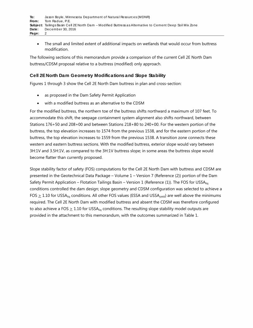
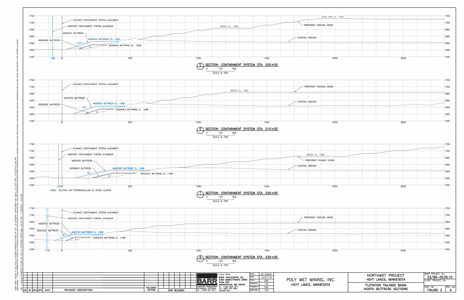
Cell 2E North Dam Geometry Modifications and Slope Stability Figures 1 through 3 show the Cell 2E North Dam buttress in plan and cross-section:
as proposed in the Dam Safety Permit Application
with a modified buttress as an alternative to the CDSM
For the modified buttress, the northern toe of the buttress shifts northward a maximum of 107 feet. To accommodate this shift, the seepage containment system alignment also shifts northward, between Stations 176+50 and 208+00 and between Stations 218+80 to 240+00. For the western portion of the buttress, the top elevation increases to 1574 from the previous 1538, and for the eastern portion of the buttress, the top elevation increases to 1559 from the previous 1538. A transition zone connects these western and eastern buttress sections. With the modified buttress, exterior slope would vary between 3H:1V and 3.5H:1V, as compared to the 3H:1V buttress slope; in some areas the buttress slope would become flatter than currently proposed.
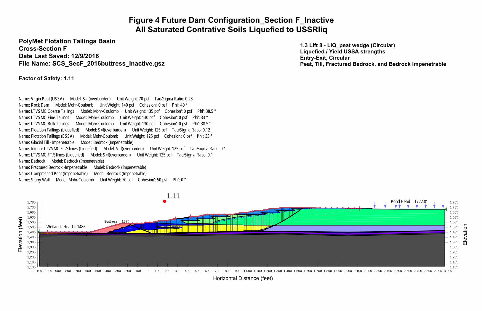
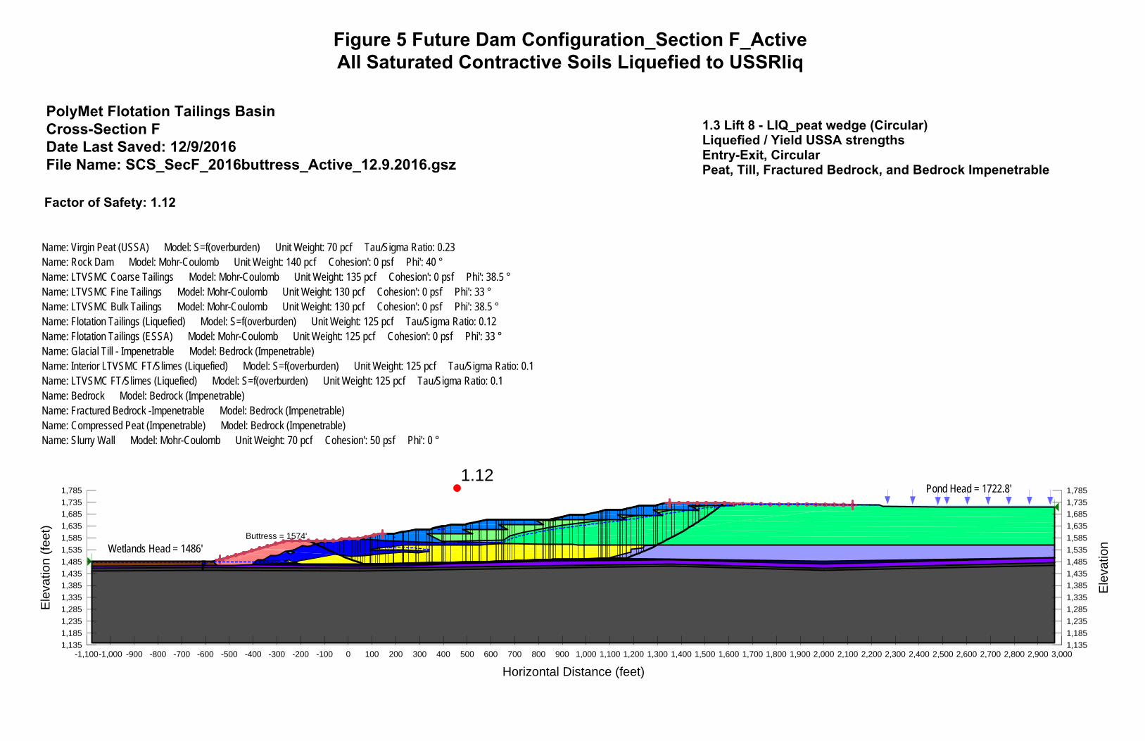
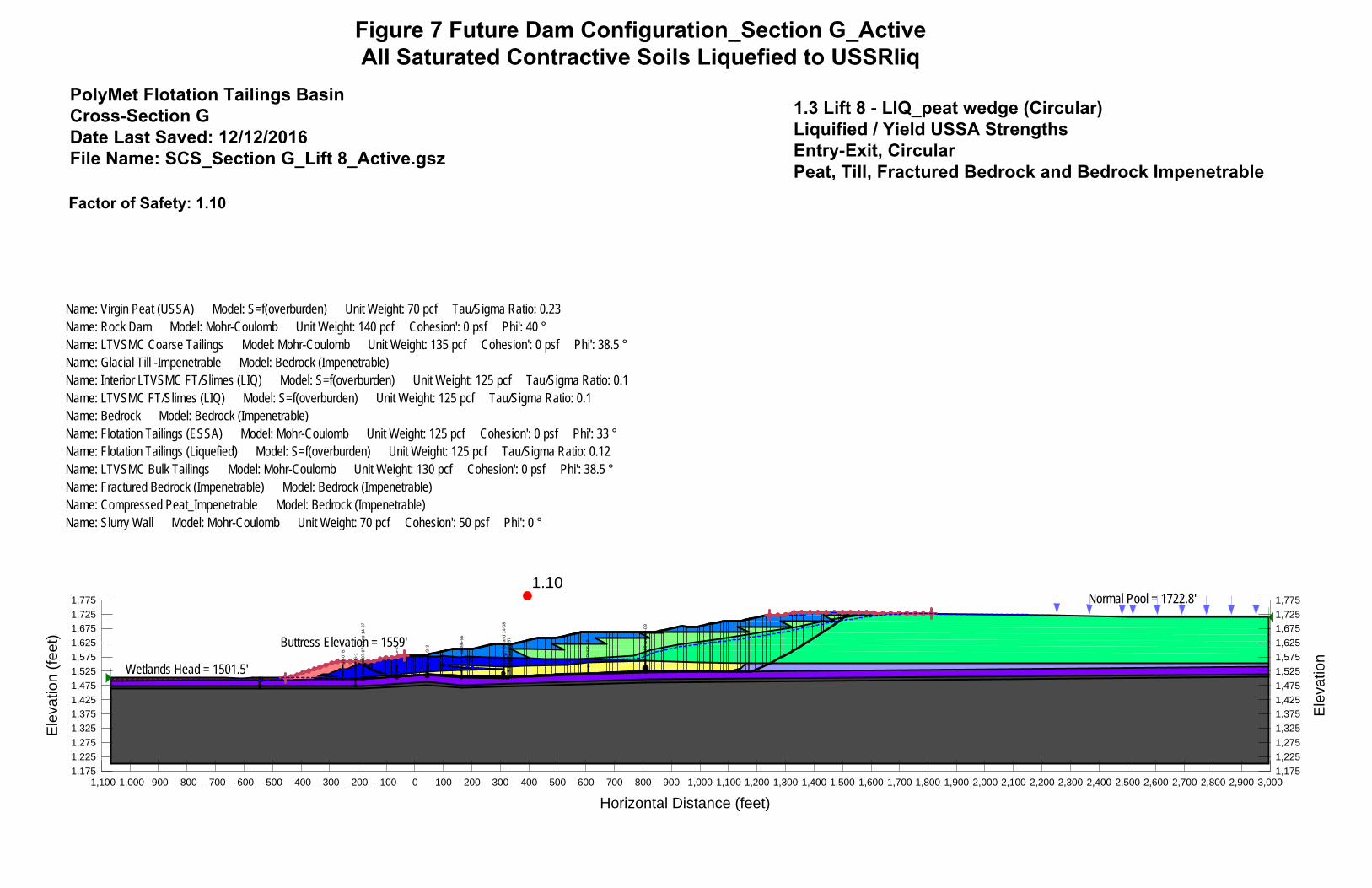
Slope stability factor of safety (FOS) computations for the Cell 2E North Dam with buttress and CDSM are presented in the Geotechnical Data Package – Volume 1 – Version 7 (Reference (2)) portion of the Dam Safety Permit Application – Flotation Tailings Basin – Version 1 (Reference (1)). The FOS for USSAliq conditions controlled the dam design; slope geometry and CDSM configuration was selected to achieve a FOS > 1.10 for USSAliq conditions. All other FOS values (ESSA and USSAyield) are well above the minimums required. The Cell 2E North Dam with modified buttress and absent the CDSM was therefore configured to also achieve a FOS > 1.10 for USSAliq conditions. The resulting slope stability model outputs are provided in the attachment to this memorandum, with the outcomes summarized in Table 1.
To: Jason Boyle, Minnesota Department of Natural Resources (MDNR) From: Tom Radue, P.E. Subject: Tailings Basin Cell 2E North Dam – Modified Buttress as Alternative to Cement Deep Soil Mix Zone Date: December 30, 2016 Page: 3
Table 1 Cell 2E North Dam Slope Stability FOS with Modified North Buttress
Figure No.
Slope Section Modeled
Slope Condition Modeled
Required Slope Stability Factor of Safety (FOS)
Slope Stability Factor of Safety
(FOS) Model Outcome
Slope Stability FOS Equal to or
Greater Than Required FOS
Yes/No
4 Section F
Lift 8 with Modified Buttress – USSAliq,
Seepage Containment
System Inactive
FOS > 1.10 FOS = 1.11 Yes
5 Section F
Lift 8 with Modified Buttress – USSAliq,
Seepage Containment System Active
FOS > 1.10 FOS = 1.12 Yes
6 Section G
Lift 8 with Modified Buttress – USSAliq,
Seepage Containment
System Inactive
FOS > 1.10 FOS = 1.10 Yes
7 Section G
Lift 8 with Modified Buttress – USSAliq,
Seepage Containment System Active
FOS > 1.10 FOS = 1.10 Yes
Construction Material Quantity and Source The modified buttress requires 3,230,000 cubic yards of fill; an increase of 2,170,000 cubic yards relative to the 1,060,000 for the current buttress proposal. Construction material quantities and placement sequencing is presented in Table 2. Construction material for the buttress, whether as designed or modified, is planned to be obtained from the rock stockpiles at Area 5.

To: Jason Boyle, Minnesota Department of Natural Resources (MDNR) From: Tom Radue, P.E. Subject: Tailings Basin Cell 2E North Dam – Modified Buttress as Alternative to Cement Deep Soil Mix Zone Date: December 30, 2016 Page: 4
Table 2 Flotation Tailings Basin Cell 2E North Buttress Development
Mine Year (end of)
Approximate Total Quantity In Place
(CY) – Proposed Buttress
Approximate Total Quantity In Place
(CY) – Modified Buttress
Cumulative Quantity Difference (CY)
Modified Buttress – Proposed Buttress
0 0 0 0
1 0 0 0
2 1,060,000 1,060,000 0
3 1,060,000 1,494,000 434,000
4 1,060,000 1,928,000 868,000
5 1,060,000 2,362,000 1,302,000
6 1,060,000 2,796,000 1,736,000
7 1,060,000 3,230,000 2,170,000
Totals 1,060,000 3,230,000 2,170,000
Air Quality Air dispersion modeling completed in support of the environmental review process and updated for the NorthMet Air Permit Application included Tailings Basin construction traffic as an emission source. Specifically, Class II modeling (Reference (3)) included fugitive dust generated from material handling and vehicle traffic on unpaved roads, and the Class I modeling (Reference (4)) included the tailpipe emissions from the construction equipment. The air emission risk analysis (AERA) included both fugitive dust and tailpipe emissions from Tailings Basin construction activities (Reference (5)).
A revised version of the Tailings Basin construction movement schedule was developed to accommodate the proposed modified buttress design. The maximum traffic rates, material handling rates and maximum number of trucks were recalculated. The movement schedule used for the previous analyses has 1,355,000 cubic yards of buttress rock moved in Mine Year 3. The maximum quantity moved in a single year (Mine Year 2) is lower under the modified buttress design (1,060,000 cubic yards per Table 2).
The Tailings Basin construction movement schedule assumes that rock for buttress construction comes from Area 5. The road segments included in the haul route from Area 5 to the north side of Cell 2E are A5B and TBI (Figure 8). Under the revised movement schedule, the maximum trips per hour for A5B and TBI is 32, while under the movement schedule for the previous buttress design the maximum number of trips for both roads is 40. VMT is directly proportional to the number of trips per hour (VMT = trips/hour * hours/day * road length * 2 trips/round trip), so the previously modeled emission rates can accommodate

To: Jason Boyle, Minnesota Department of Natural Resources (MDNR) From: Tom Radue, P.E. Subject: Tailings Basin Cell 2E North Dam – Modified Buttress as Alternative to Cement Deep Soil Mix Zone Date: December 30, 2016 Page: 5
the modified buttress construction schedule. In other words, the emissions under a modified buttress design do not exceed the previously modeled emission rates.
Buttress construction requires truck loading at the rock source (Area 5 – AREA5 on Figure 8) and unloading at the construction site (near North Dam of Cell 2E – 2EN on Figure 8). Under the proposed revised buttress design movement schedule, the maximum material handling rate at Area 5 goes down from 2398 tons/hour to 1918 tons/hour and the maximum handling rate at the North Dam of Cell 2E goes down from 4194 to 3176.
The maximum total number of trucks required over the 20-year NorthMet mine life was also recalculated under the modified buttress design with results of 29 trucks, which is lower than the 31 trucks assumed for the Class I and AERA modeling.
Based on the above calculations, the modified buttress design would not result in fugitive dust or construction equipment tailpipe emissions greater than those modeled in previous evaluations. Therefore, modeled impact to air quality would not increase above the values reported in support of the environmental review process or provided with the NorthMet Air Permit Application.
Water Quality The water quality modeling (GoldSim model) that was conducted to support the Final Environmental Impact Statement (FEIS) (Reference (6)) and permitting considers both the buttress and the CDSM. The buttress is assumed to add to the load of dissolved constituents collected by the seepage containment system with minimal effect on the quantity of water collected.
The Plant Site GoldSim model conservatively assumed a total volume for the north buttress of 3,437,700 cubic yards. Modeling documentation presented in the NorthMet Project Water Management Plan – Plant (Reference (7)) acknowledged that this was a larger volume of material than was planned, but that the actual volume would change as a result of final design. The modified buttress design volume presented in this memo (3,230,000 cubic yards per Table 2) is within the volume of buttress assumed in the GoldSim model (3,437,700 cubic yards). Because mass of the proposed modified buttress design is within the mass of buttress in the GoldSim model, the proposed change presented in this memorandum should not affect analysis of water quality nor the characterization of impacts conducted to support the FEIS or permitting.
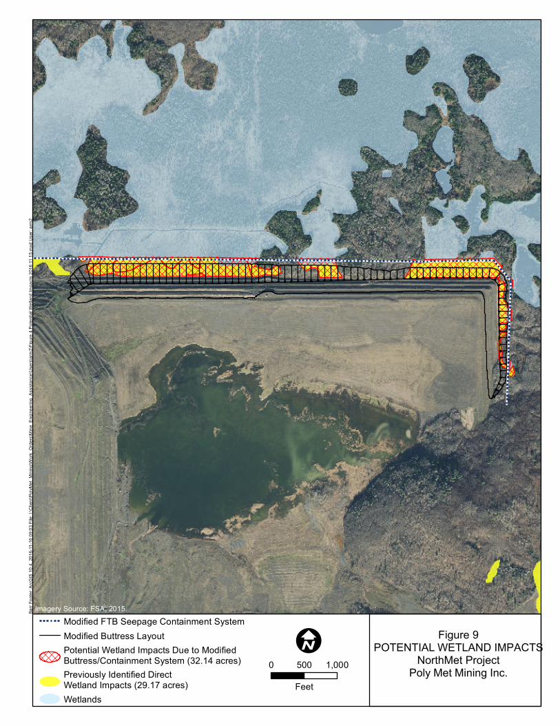
Wetlands The wetlands that are located between the toe of the Flotation Tailings Basin and the outer limit of seepage containment system construction activity were considered to be directly impacted as part of the wetland impacts analysis for the FEIS. Within these areas, the planned buttress would directly impact 29.17 acres of wetland. A modified buttress would directly impact 32.14 acres of wetlands; an increase of 2.97
To: Jason Boyle, Minnesota Department of Natural Resources (MDNR) From: Tom Radue, P.E. Subject: Tailings Basin Cell 2E North Dam – Modified Buttress as Alternative to Cement Deep Soil Mix Zone Date: December 30, 2016 Page: 6
acres over the current proposal. Figure 9 provides a comparison of the wetland area impacts for the proposed buttress and for a modified buttress alternative. The NorthMet Project Wetland Permit Application (Reference (8)) includes the mitigation proposed for the 29.17 acre wetland impact. Additional mitigation would be required for the 2.97 acre increase in wetland impact. These wetlands include deep marsh, coniferous swamp, and shallow marshes, and mitigation requirements would be dependent on the acreage of each type of wetland impacted. This additional mitigation will be accounted for under the appropriate regulatory processes (i.e., USACE, MDNR/WCA).

To: Jason Boyle, Minnesota Department of Natural Resources (MDNR) From: Tom Radue, P.E. Subject: Tailings Basin Cell 2E North Dam – Modified Buttress as Alternative to Cement Deep Soil Mix Zone Date: December 30, 2016 Page: 7
Certification
I hereby certify that this plan, specification, or report was prepared by me or under my direct supervision and that I am a duly Licensed Professional Engineer under the laws of the state of Minnesota.
Thomas J. Radue PE #: 20951
References 1. Barr Engineering Co. NorthMet Dam Safety Permit Application - Flotation Tailings Basin. July 2016.
2. Poly Met Mining Inc. NorthMet Project Geotechnical Data Package Vol 1 - Flotation Tailings Basin (v7).July 2016.
3. Barr Engineering Co. Class II Plant Site Air Quality Dispersion Modeling Report v2 - NorthMet Project.November 2012.
4. Barr Engineering Company. Class I Area Air Dispersion Modeling (v2). May 2012.
5. Barr Engineering Co. Supplemental Air Emissions Risk Analysis (AERA) – Plant Site, NorthMet Project.March 2013.
6. Minnesota Department of Natural Resources, U.S. Army Corps of Engineers and U.S. ForestService. Final Environmental Impact Statement: NorthMet Mining Project and Land Exchange. November 2015.
7. Poly Met Mining Inc. NorthMet Project Water Management Plan - Plant (v5). July 2016.
8. —. Revised Wetland Permit Application (v2). August 19, 2013.

1.11
PolyMet Flotation Tailings BasinCross-Section FDate Last Saved: 12/9/2016File Name: SCS_SecF_2016buttress_Inactive.gsz
Figure 4 Future Dam Configuration_Section F_Inactive All Saturated Contrative Soils Liquefied to USSRliq
Wetlands Head = 1486'
Pond Head = 1722.8'
Name: Virgin Peat (USSA) Model: S=f(overburden) Unit Weight: 70 pcf Tau/Sigma Ratio: 0.23 Name: Rock Dam Model: Mohr-Coulomb Unit Weight: 140 pcf Cohesion': 0 psf Phi': 40 ° Name: LTVSMC Coarse Tailings Model: Mohr-Coulomb Unit Weight: 135 pcf Cohesion': 0 psf Phi': 38.5 ° Name: LTVSMC Fine Tailings Model: Mohr-Coulomb Unit Weight: 130 pcf Cohesion': 0 psf Phi': 33 ° Name: LTVSMC Bulk Tailings Model: Mohr-Coulomb Unit Weight: 130 pcf Cohesion': 0 psf Phi': 38.5 ° Name: Flotation Tailings (Liquefied) Model: S=f(overburden) Unit Weight: 125 pcf Tau/Sigma Ratio: 0.12 Name: Flotation Tailings (ESSA) Model: Mohr-Coulomb Unit Weight: 125 pcf Cohesion': 0 psf Phi': 33 ° Name: Glacial Till - Impenetrable Model: Bedrock (Impenetrable) Name: Interior LTVSMC FT/Slimes (Liquefied) Model: S=f(overburden) Unit Weight: 125 pcf Tau/Sigma Ratio: 0.1 Name: LTVSMC FT/Slimes (Liquefied) Model: S=f(overburden) Unit Weight: 125 pcf Tau/Sigma Ratio: 0.1 Name: Bedrock Model: Bedrock (Impenetrable) Name: Fractured Bedrock -Impenetrable Model: Bedrock (Impenetrable) Name: Compressed Peat (Impenetrable) Model: Bedrock (Impenetrable) Name: Slurry Wall Model: Mohr-Coulomb Unit Weight: 70 pcf Cohesion': 50 psf Phi': 0 °
Buttress = 1574'
Factor of Safety: 1.11
1.3 Lift 8 - LIQ_peat wedge (Circular)Liquefied / Yield USSA strengthsEntry-Exit, CircularPeat, Till, Fractured Bedrock, and Bedrock Impenetrable
Horizontal Distance (feet)
-1,100 -1,000 -900 -800 -700 -600 -500 -400 -300 -200 -100 0 100 200 300 400 500 600 700 800 900 1,000 1,100 1,200 1,300 1,400 1,500 1,600 1,700 1,800 1,900 2,000 2,100 2,200 2,300 2,400 2,500 2,600 2,700 2,800 2,900 3,000
Ele
vatio
n
1,135
1,185
1,235
1,285
1,335
1,385
1,435
1,485
1,535
1,585
1,635
1,685
1,735
1,785
Ele
vatio
n (f
eet)
1,135
1,185
1,235
1,285
1,335
1,385
1,435
1,485
1,535
1,585
1,635
1,685
1,735
1,785
1.12
PolyMet Flotation Tailings BasinCross-Section FDate Last Saved: 12/9/2016File Name: SCS_SecF_2016buttress_Active_12.9.2016.gsz
Wetlands Head = 1486'
Pond Head = 1722.8'
Name: Virgin Peat (USSA) Model: S=f(overburden) Unit Weight: 70 pcf Tau/Sigma Ratio: 0.23 Name: Rock Dam Model: Mohr-Coulomb Unit Weight: 140 pcf Cohesion': 0 psf Phi': 40 ° Name: LTVSMC Coarse Tailings Model: Mohr-Coulomb Unit Weight: 135 pcf Cohesion': 0 psf Phi': 38.5 ° Name: LTVSMC Fine Tailings Model: Mohr-Coulomb Unit Weight: 130 pcf Cohesion': 0 psf Phi': 33 ° Name: LTVSMC Bulk Tailings Model: Mohr-Coulomb Unit Weight: 130 pcf Cohesion': 0 psf Phi': 38.5 ° Name: Flotation Tailings (Liquefied) Model: S=f(overburden) Unit Weight: 125 pcf Tau/Sigma Ratio: 0.12 Name: Flotation Tailings (ESSA) Model: Mohr-Coulomb Unit Weight: 125 pcf Cohesion': 0 psf Phi': 33 ° Name: Glacial Till - Impenetrable Model: Bedrock (Impenetrable) Name: Interior LTVSMC FT/Slimes (Liquefied) Model: S=f(overburden) Unit Weight: 125 pcf Tau/Sigma Ratio: 0.1 Name: LTVSMC FT/Slimes (Liquefied) Model: S=f(overburden) Unit Weight: 125 pcf Tau/Sigma Ratio: 0.1 Name: Bedrock Model: Bedrock (Impenetrable) Name: Fractured Bedrock -Impenetrable Model: Bedrock (Impenetrable) Name: Compressed Peat (Impenetrable) Model: Bedrock (Impenetrable) Name: Slurry Wall Model: Mohr-Coulomb Unit Weight: 70 pcf Cohesion': 50 psf Phi': 0 °
Buttress = 1574'
Factor of Safety: 1.12
1.3 Lift 8 - LIQ_peat wedge (Circular)Liquefied / Yield USSA strengthsEntry-Exit, CircularPeat, Till, Fractured Bedrock, and Bedrock Impenetrable
Figure 5 Future Dam Configuration_Section F_Active All Saturated Contractive Soils Liquefied to USSRliq
Horizontal Distance (feet)
-1,100-1,000 -900 -800 -700 -600 -500 -400 -300 -200 -100 0 100 200 300 400 500 600 700 800 900 1,000 1,100 1,200 1,300 1,400 1,500 1,600 1,700 1,800 1,900 2,000 2,100 2,200 2,300 2,400 2,500 2,600 2,700 2,800 2,900 3,000
Ele
vatio
n
1,135
1,185
1,235
1,285
1,335
1,385
1,435
1,485
1,535
1,585
1,635
1,685
1,735
1,785
Ele
vatio
n (f
eet)
1,135
1,185
1,235
1,285
1,335
1,385
1,435
1,485
1,535
1,585
1,635
1,685
1,735
1,785

1.10
PolyMet Flotation Tailings BasinCross-Section GDate Last Saved: 12/12/2016File Name: SCS_Section G_Lift 8_Inactive.gsz
1.3 Lift 8 - LIQ_peat wedge (Circular)Liquified / Yield USSA StrengthsEntry-Exit, CircularPeat, Till, Fractured Bedrock and Bedrock Impenetrable
Wetlands Head = 1501.5'
Factor of Safety: 1.10
Name: Virgin Peat (USSA) Model: S=f(overburden) Unit Weight: 70 pcf Tau/Sigma Ratio: 0.23 Name: Rock Dam Model: Mohr-Coulomb Unit Weight: 140 pcf Cohesion': 0 psf Phi': 40 ° Name: LTVSMC Coarse Tailings Model: Mohr-Coulomb Unit Weight: 135 pcf Cohesion': 0 psf Phi': 38.5 ° Name: Glacial Till -Impenetrable Model: Bedrock (Impenetrable) Name: Interior LTVSMC FT/Slimes (LIQ) Model: S=f(overburden) Unit Weight: 125 pcf Tau/Sigma Ratio: 0.1 Name: LTVSMC FT/Slimes (LIQ) Model: S=f(overburden) Unit Weight: 125 pcf Tau/Sigma Ratio: 0.1 Name: Bedrock Model: Bedrock (Impenetrable) Name: Flotation Tailings (ESSA) Model: Mohr-Coulomb Unit Weight: 125 pcf Cohesion': 0 psf Phi': 33 ° Name: Flotation Tailings (Liquefied) Model: S=f(overburden) Unit Weight: 125 pcf Tau/Sigma Ratio: 0.12 Name: LTVSMC Bulk Tailings Model: Mohr-Coulomb Unit Weight: 130 pcf Cohesion': 0 psf Phi': 38.5 ° Name: Fractured Bedrock (Impenetrable) Model: Bedrock (Impenetrable) Name: Compressed Peat_Impenetrable Model: Bedrock (Impenetrable) Name: Slurry Wall Model: Mohr-Coulomb Unit Weight: 70 pcf Cohesion': 50 psf Phi': 0 °
Normal Pool = 1722.8'
07
-07
B
G-1 07
-07
C a
nd
14
-07
G-2 G-3
DH
96
-56
07
-08
an
d 1
4-0
8D
H9
6-5
7
DH
96
-58
07
-09
an
d 1
4-0
9
Figure 6 Future Dam Configuration_Section G_Inactive All Saturated Contrative Soils Liquefied to USSRliq
Buttress Elevation = 1559'
Horizontal Distance (feet)
-1,100 -900 -800 -700 -600 -500 -400 -300 -200 -100 0 100 200 300 400 500 600 700 800 900 1,000 1,100 1,200 1,300 1,400 1,500 1,600 1,700 1,800 1,900 2,000 2,100 2,200 2,300 2,400 2,500 2,600 2,700 2,800 2,900 3,000
Ele
vatio
n
1,175
1,225
1,275
1,325
1,375
1,425
1,475
1,525
1,575
1,625
1,675
1,725
1,775
Ele
vatio
n (f
eet)
1,175
1,225
1,275
1,325
1,375
1,425
1,475
1,525
1,575
1,625
1,675
1,725
1,775
1.10
PolyMet Flotation Tailings BasinCross-Section GDate Last Saved: 12/12/2016File Name: SCS_Section G_Lift 8_Active.gsz
1.3 Lift 8 - LIQ_peat wedge (Circular)Liquified / Yield USSA StrengthsEntry-Exit, CircularPeat, Till, Fractured Bedrock and Bedrock Impenetrable
Wetlands Head = 1501.5'
Factor of Safety: 1.10
Name: Virgin Peat (USSA) Model: S=f(overburden) Unit Weight: 70 pcf Tau/Sigma Ratio: 0.23 Name: Rock Dam Model: Mohr-Coulomb Unit Weight: 140 pcf Cohesion': 0 psf Phi': 40 ° Name: LTVSMC Coarse Tailings Model: Mohr-Coulomb Unit Weight: 135 pcf Cohesion': 0 psf Phi': 38.5 ° Name: Glacial Till -Impenetrable Model: Bedrock (Impenetrable) Name: Interior LTVSMC FT/Slimes (LIQ) Model: S=f(overburden) Unit Weight: 125 pcf Tau/Sigma Ratio: 0.1 Name: LTVSMC FT/Slimes (LIQ) Model: S=f(overburden) Unit Weight: 125 pcf Tau/Sigma Ratio: 0.1 Name: Bedrock Model: Bedrock (Impenetrable) Name: Flotation Tailings (ESSA) Model: Mohr-Coulomb Unit Weight: 125 pcf Cohesion': 0 psf Phi': 33 ° Name: Flotation Tailings (Liquefied) Model: S=f(overburden) Unit Weight: 125 pcf Tau/Sigma Ratio: 0.12 Name: LTVSMC Bulk Tailings Model: Mohr-Coulomb Unit Weight: 130 pcf Cohesion': 0 psf Phi': 38.5 ° Name: Fractured Bedrock (Impenetrable) Model: Bedrock (Impenetrable) Name: Compressed Peat_Impenetrable Model: Bedrock (Impenetrable) Name: Slurry Wall Model: Mohr-Coulomb Unit Weight: 70 pcf Cohesion': 50 psf Phi': 0 °
Normal Pool = 1722.8'
07
-07
B
G-1 07
-07
C a
nd
14
-07
G-2 G-3
DH
96
-56
07
-08
an
d 1
4-0
8D
H9
6-5
7
DH
96
-58
07
-09
an
d 1
4-0
9
Figure 7 Future Dam Configuration_Section G_Active All Saturated Contractive Soils Liquefied to USSRliq
Buttress Elevation = 1559'
Horizontal Distance (feet)
-1,100-1,000 -900 -800 -700 -600 -500 -400 -300 -200 -100 0 100 200 300 400 500 600 700 800 900 1,000 1,100 1,200 1,300 1,400 1,500 1,600 1,700 1,800 1,900 2,000 2,100 2,200 2,300 2,400 2,500 2,600 2,700 2,800 2,900 3,000
Ele
vatio
n
1,175
1,225
1,275
1,325
1,375
1,425
1,475
1,525
1,575
1,625
1,675
1,725
1,775
Ele
vatio
n (f
eet)
1,175
1,225
1,275
1,325
1,375
1,425
1,475
1,525
1,575
1,625
1,675
1,725
1,775

"6
"6
"6
"6
"6
"6
"6
A5B001-012
BCA001-067
CAS001-074JSH001-038
JHD001-052
JSD001-039
JDW001-047
TBI001-124JWU001-045
JWN001-043
WUE001-116
HMR001-055
TWW001-033
Coal Ash Landfill(Source Not Modeled)
SD
SPD
HM4
2EN
AREA5
S4, Stockpile G
1ES, S3
Barr
Foote
r: ArcG
IS 10
.4, 20
16-08
-03 13
:45 Fi
le: I:\
Clien
t\Poly
Met_M
ining
\Work
_Orde
rs\Pe
rmitti
ng\A
ir_Pe
rmit_
Appli
catio
n\Map
s\Rep
ort\A
ppen
dix_A
\Large
Figu
re A1
4 Tail
ings B
asin
Road
Segm
ent L
ayou
t.mxd
Use
r: arm
2
"6 Tailings Handling SourcesPlant Site Ambient Air Boundary
TAILINGS BASINROAD SEGMENT LAYOUT
NorthMet ProjectPoly Met Mining, Inc.
Figure 8
I0 0.5 10.25
Kilometers
Imagery Source: FSA, 2015.Barr
Foote
r: ArcG
IS 10
.4, 20
16-11
-16 09
:03 Fi
le: I:\
Clien
t\Poly
Met_M
ining
\Work
_Orde
rs\Mi
ne_E
ngine
ering
_Ass
istan
ce\U
sers\
arm2\F
igure
4 Pote
ntial
Wetla
nd Im
pacts
2016
11 15
.mxd
Use
r: arm
2
Modified FTB Seepage Containment SystemModified Buttress LayoutPotential Wetland Impacts Due to ModifiedButtress/Containment System (32.14 acres)Previously Identified DirectWetland Impacts (29.17 acres)Wetlands
Figure 9POTENTIAL WETLAND IMPACTS
NorthMet ProjectPoly Met Mining Inc.
I0 1,000500
Feet