Embed Size (px)
Citation preview
1121 Drayton Street
Newberry, South Carolina 29108 Phone: (803) 276-3211 Fax: (803) 276-3212
www.peteduty.com
Transmittal Letter April 26, 2018 Via E-Mail Mr. Chad Abrams North Charleston Sewer District P.O. Box 63009 North Charleston, South Carolina 29419 Re: North Charleston – Stoney Road PS Upgrade – PO # 181769 Enclosed please find the following items for the above job. Item Qty. Description 1. 1 E-Submittals For North Charleston – Stoney Road Please Return: 1. One Copy Marked Approved Or Noted With Correction For Release To Final Production. Confirm Voltage And Phase Before Ordering.

SUBMITTAL
PETE DUTY & ASSOCIATES
South Carolina Office 1121 Drayton Street Newberry, SC 29108
(803) 276-3211
Main Office 2219 Leah Drive
Hillsborough, NC 27278 (919) 245-5070
Project: N. Charleston – Stoney Road PS Engineer: N. Charleston Sewer Contractor: TBD
1121 Drayton Street • Newberry, South Carolina 29108 • (803) 276‐3211 • Fax (803) 276‐3212
Water & Sewage Pumping and Treatment Equipment
2219 Leah Drive • Hillsborough, North Carolina 27278 • (919) 245‐5070 • Fax (919) 245‐5071
SUBMITTAL LETTER
Aril 26, 2018 Via E-Mail To: Chad Abrams @ North Charleston Sewer From: Keith Weeks @ Pete Duty & Associates, Inc. Re: North Charleston – Stoney Road Pump Station Upgrade Pete Duty & Associates, Inc. is pleased to submit the following equipment for your approvals: (2) ABS XFP-200J-CH2, PE-1040/4, 140 HP, 460 Volt, 3 Phase, With 65' Power Cables, Closed Loop Cooling, SS Lifting Bails And SS Kellem
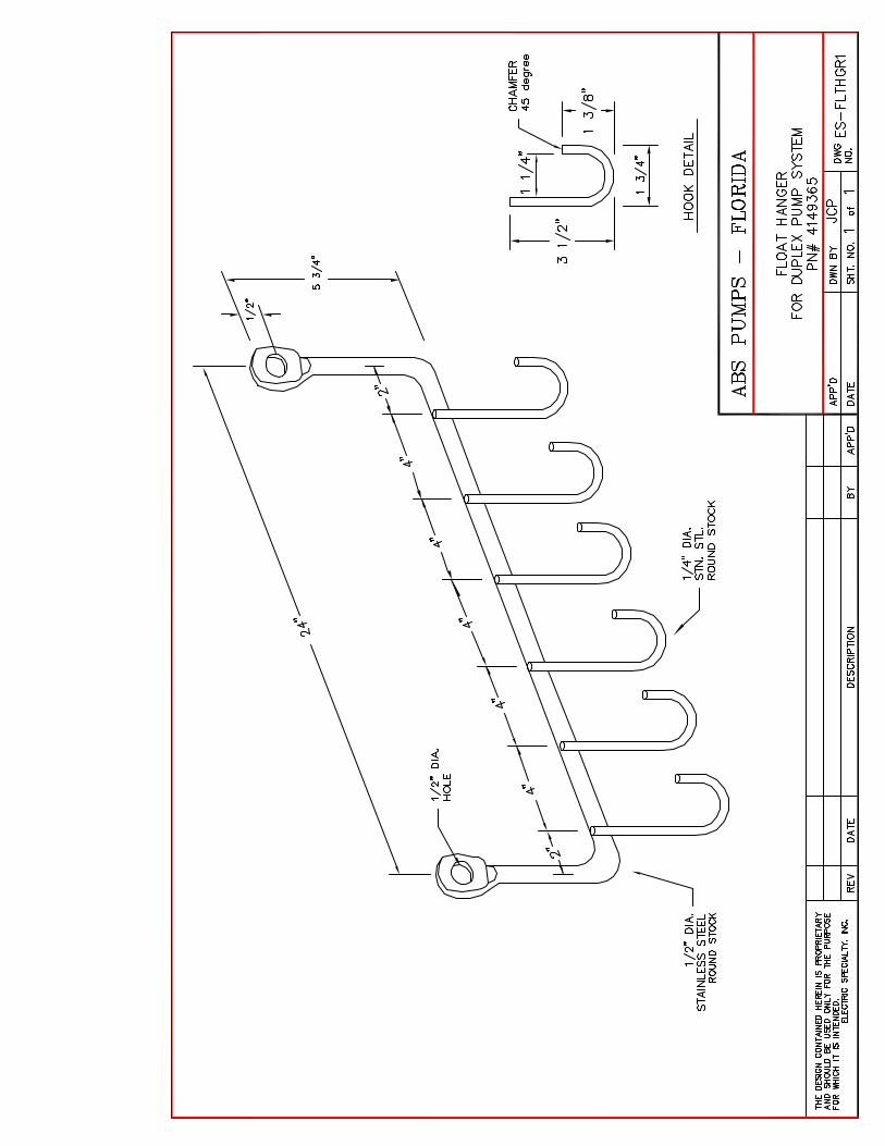
Grips Rated For 3040 GPM @ 133’ TDH (2) ABS 8" Guide Rail Assemblies w/ Integral Elbows & SS Hardware Kits (2) Stainless Steel Lifting Chains w/Shackles (28' Each) (1) Six Hook Cable Bracket – 316 SS
(1) Control Interface Duplex VFD Pump Control Panel In A NEMA 1 Painted Steel Enclosure Per Specification Section 11313 To
Include (2) Endress + Hauser Transducers, (1) MPE Probe & (1) LPC420R-RM Converter, Allen-Bradley Micrologic PLC With Square D Magellis HMI – (VFD’s AB Powerflex 400)
(1) Lot Spare Parts To Include One Repair Kit With Cable Seals (1) Start Up Services (Non-Taxable) If you have any questions, or need additional information, please feel free to contact me.
Cordially, Keith Weeks
WARRANTY
Page | 1
5 Year Pro-Rated | Municipal
© Sulzer
Scan For More Info
DS
-Z07-0
01
RE
V:
0 D
AT
E:
08/1
7S
pe
cific
ations
Subje
ct t
o C
han
ge
With
out
Notic
e
XFP, AFP, AFL(X), VUP(X)* Permanent Type Installation
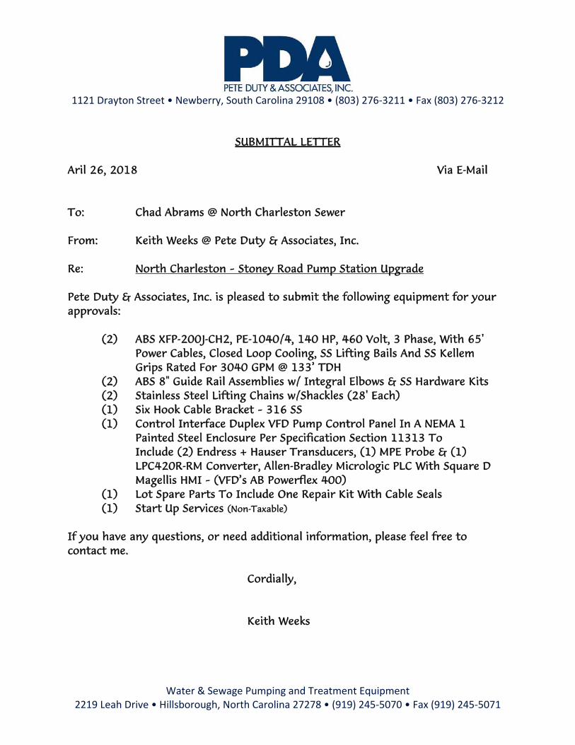
Manufacturer warrants the above referenced ABS brand equipment ("Products") to be free from defects in workmanship and materials as follows:
The warranty period shall be five (5) years from date of manufacturer provided startup, not to exceed 5 years 6 months from date of shipment. If authorized startup is not performed, the warranty shall be five (5) years from date of shipment. This warranty is contingent upon purchaser's or end user's payment of the applicable percentage of the list price (list price minus covered %) of the following parts in effect at time of replacement.
Warranty Coverage
Months 0 - 36 37 - 48 49 - 60
Percentage 100% Parts / 100% Labor 75% Parts / 75% Labor 50% Parts / 50% Labor
When used in temporary/portable applications, the warranty period shall expire on the earliest of the below dates:
i) one (1) year from date of installation of the Products; or ii) eighteen (18) months from date of shipment of the Products from Manufacturer.
Products or parts thereof that are replaced or repaired under warranty during the original warranty period, shall be covered under this warranty until the expiration of the original warranty period or ninety (90) days from the date of such replacement or repair, whichever is later. In any event, such extended warranty period shall not exceed ninety (90) days after the expiration of the original warranty period.
The warranties stated above are contingent upon start-up of the equipment on site by an authorized Manufacturer's representative, as verified by receipt of start-up reports completed and signed by an authorized Manufacturer's representative. If during the warranty period, any Products fail to meet the requirements set out in this warranty, the purchaser or end user shall give written notification to Manufacturer stating the reasons therefor. Upon receipt of prior written authorization from Manufacturer, Products shall be transported to Manufacturer's authorized service center, prepaid, at purchaser or end-user's cost. Manufacturer’s sole obligation shall be to repair, modify or replace Products or parts thereof, at Manufacturer's sole option. Products repaired under this warranty will be returned with freight prepaid. Products must be repaired by an authorized Manufacturer repair center for warranty coverage to be considered.
All protection features (such as moisture sensors, bearing monitors, and thermal overloads) incorporated in the Products must be connected and operable for warranty coverage. This warranty is valid only if Manufacturer supplied or authorized alarm monitoring components, cables and control components/panels are used.
This warranty shall not apply to any Products or parts thereof which have been (i) subjected to misuse, misapplication, accident, alteration, neglect, failure to act in a timely manner to address alarms/warnings, or physical damage; (ii) installed, operated, and/or maintained in a manner which is contrary to Manufacturer's written instructions as it pertains to installation, operation and maintenance of the Products, including but without limitation to being operated without being connected to monitoring devices supplied with specific products for protection; (iii) used in an application or for pumping liquids other than the use for which it is intended as specified in Manufacturer's product literature; (iv) damaged due to a defective power supply, improper electrical protection, faulty repair, ordinary wear and tear, corrosion, erosion or chemical attack, an act of God, an act of war or by an act of terrorism; (v) damaged resulting from the use of accessory equipment not sold by Manufacturer or not approved by Manufacturer for use in connection with Manufacturer's products; or (vi) repaired or altered without Manufacturer’s written consent.
This warranty does not cover costs for standard and/or scheduled maintenance that is performed, nor does it cover Manufacturer's parts that, by virtue of their operation, require replacement through normal wear (aka: Wear Parts), unless a defect in material or workmanship is determined by Manufacturer. Wear Parts are defined as cutters, cutting plates, seals, bearings, impellers/propellers, diffusers, wear rings (stationary or rotating), volutes (when used in an abrasive environment), oil, grease, cooling fluids and/or any items deemed necessary to perform and meet the requirements of normal maintenance on all Manufacturer’s equipment.
Manufacturer shall not be liable for any special, indirect, consequential, or punitive damages, or profit loss of any kind. Major components not manufactured by the Manufacturer are covered by the original manufacturer’s warranty in lieu of this warranty. In addition to any other special, indirect or consequential damages referenced above, Manufacturer shall not be responsible for travel expenses, rented (replacement) equipment, pump removal fees, installation fees, outside contractors fees, or unauthorized repair shop expenses.
This warranty shall extend only to the initial end user.
All other warranties, conditions and representation, expressed or implied by statue, common law or otherwise, in relation to the supply of the products including but not limited to the implied warranties or merchantability and fitness for a particular purpose are excluded to the extent permitted by law.
*This warranty is applicable to Products supplied by Sulzer Pumps Solutions Inc. or Sulzer Pumps (Canada) Inc. for installation in the U.S.A. or Canada, unless specifically indicated otherwise in writing by Manufacturer.

60Discharge
DN200Frequency
Density
62,32 lb/ft³
Viscosity
1,005 mm²/s
Testnorm Rated speed
1784 rpm
Date
2018-04-25Flow
3040 US g.p.m.
Hz
340
80,5%
PE1040/4
340
340
340
Head
Shaft power P2
Hydraulic efficiency
NPSH-values
H / ft
102030405060708090
100110120130140150160170180190200210220
∆p / at
0,5
1
1,5
2
2,5
3
3,5
4
4,5
5
5,5
6
6,5
P₂ / hp
20
40
60
80
100
η / %
0
20
40
60
Q / US g.p.m.0 400 800 1200 1600 2000 2400 2800 3200 3600 4000
NPSH / ft
10
20
30
40
50
A1133 4.048133 4.048
127.5127.5
80.3780.37
3040
28.92
3040
28.92
Impeller size13,4 inch 2-vane channel impeller
ISO 9906: 2012, HI 11.6/14.6 Gr 2B
Shaft powerHead Hydraulic efficiency NPSH
133 ft 128 hp 80,4 % 28,9 ft
Power input
133 hp
N° of vanes Impeller Solid size Revision2
Sulzer reserves the right to change any data and dimensions without prior notice and can not be held responsible for the use of information contained in this software.
3,54 x 4,92 inch
Spaix® 4, Version 4.3.9 - 2017/11/23 (Build 324)Dec-2017Data version
XFP 200J-CH2 60 HZXFP 200J-CH2 60 HZ
Pump performance curvesCurve number
Reference curve

Starting current
4 2018-04-25
Tolerance according to VDE 0530 T1 12.84 for rated power
1330 A 35,6 lb ft²
1,3
Rated power
139 hp
Service factor
Starting torque No. starts per hour
1230 lbf ftMoment of inertia
10
Nominal Speed
1780 rpm
Number of poles Rated voltage Date
P2/P2n / %0 10 20 30 40 50 60 70 80 90 100 110 120
0
0,05
0,1
0,15
0,2
0,25
0,3
0,35
0,4
0,45
0,5
0,55
0,6
0,65
0,7
0,75
0,8
0,85
0,9
0,95
1
1,05
1,1
1,15
1,2
1,25
1,3
P₁ / hp
0
10
20
30
40
50
60
70
80
90
100
110
120
130
140
150
160
170
180
P₂ / hp0 10 20 30 40 50 60 70 80 90 100 110 120 130 140 150 160 170 180
n / rpm
0
100
200
300
400
500
600
700
800
900
1000
1100
1200
1300
1400
1500
1600
1700
1800
1900
2000
2100
2200
2300
91,45 %
0.870.87
132.9132.9A10% 25% 50% 75% 100% 125%
127.5
1784
127.5
1784
— cos φ — n — I/In — s — P₁ — M/Mn — η
480 V
Spaix® 4, Version 4.3.9 - 2017/11/23 (Build 324)Sulzer reserves the right to change any data and dimensions without prior notice and can not be held responsible for the use of information contained in this software. Dec-2017Data version
Motor performance curve
PE1040/4
PE5Frequency
Symbol No load 25 % 50 % 75 % 100 % 125 %
P₂ / hp 0 34,87 69,73 104,6 139,5 174,3P₁ / hp 1,642 37,1 73,04 108,8 145,6 182,9η / % 0 93,98 95,48 96,1 95,81 95,29n / rpm 1798 1795 1791 1787 1783 1779cos φ 0,03017 0,4942 0,7277 0,8353 0,8818 0,8918I / A 48,81 67,34 90,03 116,9 148,1 184s / % 0,1109 0,2789 0,4978 0,7244 0,9433 1,167M / lbf ft 0 102 204,5 307,4 410,8 514,7
Hz60

TECHNICAL DATA
Page | 1 © Sulzer
Scan For More Info
DS
-E02
-056
RE
V: 3
DA
TE
: 1
0/1
6 S
pecific
ation
s S
ubje
ct
to C
ha
ng
e W
itho
ut
Notice
XFP 200J-CH2 | 8”, 4 Pole, 3-Phase, 60 Hz, PE5
Submersible Motor Specifications, PE5 Frame
Motor Design NEMA design B, squirrel cage induction
Motor Type Fully enclosed Premium Efficiency submersible, IP68 protection rating
Motor Efficiency Standard and Rating IEC 60034-30, IE3 rating
Motor Efficiency Test Protocol IEC 60034-2-1
Insulation Material Class H, 180ºC (356ºF), copper windings
Motor Filling Medium Air
Temperature Rise Class A
Maximum Fluid Temperature 40ºC (104ºF) continuous, 50ºC (122ºF) intermittent
Cooling System OPT Closed-loop, non-toxic glycol/water mixture (⅓ / ⅔)
Motor Protection
Thermal
STD
<100 HP Normally closed bimetallic switch in each phase, connected in series, 140ºC (284ºF) +/- 5ºC (41ºF) opening temperature
≥100 HP
Normally closed bimetallic switch in each phase, connected in series, 140ºC (284ºF) +/- 5ºC (41ºF) opening temperature, plus 100Ω RTD (PT100) in winding, upper bearing, and lower bearing
OPT
<100 HP
STD (<100 HP) plus: upper and lower bearing bimetallic switches or 100Ω RTD (PT100) in winding (option of one RTD or three RTDs in stator) and RTDs in lieu of upper and lower bearing bimetallic switches
≥100 HP STD (≥100 HP) plus: three 100Ω RTDs (PT100) in windings in lieu of one
Leakage STD
<100 HP Moisture detection probe in seal sensing chamber (for use with appropriate relay)
≥100 HP Moisture detection probe in seal sensing chamber, motor housing, and junction chamber (for use with appropriate relay)
OPT <100 HP STD plus: probes in motor housing and junction chamber
Vibration OPT Vibration sensor (4-20 mA) in junction chamber
Sensing Chamber Filling Medium Oil
Bearing Type
Upper STD Cylindrical roller, permanently lubricated
OPT STD plus: electrically insulated
Lower Dual angular contact ball bearings plus single cylindrical roller bearing, permanently lubricated
Motor Starter Types Suitable for use with electronic soft starters, and PWM type Variable Frequency Drives
1
Maximum Starts per Hour 10 evenly spaced w/ soft starters; N/A with PWM type VFDs
Inverter Duty Rating Motors meet NEMA MG1, part 31 requirements
Maximum Submergence 20 meters (65 feet) Available Voltages 230, 460, 600 (consult factory for other voltages)
Voltage Tolerance from Rated +/-10%
Agency Approvals Factory Mutual, CSA
Explosion Proof Rating NEC 500 Class 1, Division 1, Group C & D, Class T3C max surface temp
1 Output filters may be required on VFDs. See document DS-E00-001 for details.
Motor Ratings, PE5 Frame
Motor Model Input Power (P1)
Rated Power Output
(P2)
Nominal RPM
Rated Voltage
Full Load Amps
Locked Rotor Amps
NEMA Code Letter
NEMA Service Factor
Motor Efficiency at % Load
Power Factor at % Load
100 75 50 100 75 50
PE 630/4 66.1 kW 63 kW 84 HP
1784
230 C/F C/F
J 1.3 95.3 95.3 94.2 .885 .840 .732 460 94 750
600 72 575
PE 860/4 90.2 kW 86 kW 115 HP
1784 230 C/F C/F
K 1.3 95.4 95.5 94.9 .868 .812 .690 460 130 1239 600 100 950
PE 1040/4 108.7 kW 104 kW 140 HP
1784 230 C/F C/F
J 1.3 95.8 96.1 95.5 .882 .835 .728 460 155 1390 600 119 1066
PE 1250/4 130.7 kW 125 kW 168 HP
1784
230 C/F C/F
J 1.3 95.7 95.8 94.7 .893 .852 .750 460 184 1616
600 141 1239
The picture above may differ from the actual product. For illustrative purposes only.
TECHNICAL DATA
Page | 2 © Sulzer
Scan For More Info
DS
-E02
-056
RE
V: 3
DA
TE
: 1
0/1
6 S
pecific
ation
s S
ubje
ct
to C
ha
ng
e W
itho
ut
Notice
XFP 200J-CH2 | 8”, 4 Pole, 3-Phase, 60 Hz, PE5
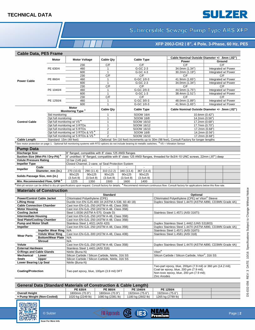
Cable Data, PE5 Frame
Power Cable
Motor Motor Voltage Cable Qty Cable Type Cable Nominal Outside Diameter +/- .5mm (.02”)
Power Ground
PE 630/4
230 C/F C/F C/F C/F
460 1 G-GC 2-3 34.0mm (1.34") Integrated w/ Power
600 1 G-GC 4-3 30.2mm (1.19") Integrated w/ Power
PE 860/4
230 C/F C/F C/F C/F
460 1 G-GC 1/0-3 41.9mm (1.65") Integrated w/ Power
600 1 G-GC 2-3 34.0mm (1.34") Integrated w/ Power
PE 1040/4
230 C/F C/F C/F C/F
460 1 G-GC 2/0-3 44.5mm (1.75") Integrated w/ Power
600 1 G-GC 1-3 38.4mm (1.51") Integrated w/ Power
PE 1250/4
230 C/F C/F C/F C/F
460 1 G-GC 3/0-3 48.0mm (1.89") Integrated w/ Power
600 1 G-GC 1/0-3 41.9mm (1.65") Integrated w/ Power
Control Cable
Motor Monitoring Type
3
Cable Qty Cable Type Cable Nominal Outside Diameter +/- .5mm (.02”)
Std monitoring 1 SOOW 16/4 10.6mm (0.42")
Opt full monitoring 1 SOOW 16/8 14.2mm (0.56")
Opt full monitoring w/ VS 4 1 SOOW 16/10 17.2mm (0.68")
Opt full monitoring w/ 3 RTDs 1 SOOW 16/12 17.7mm (0.70")
Opt full monitoring w/ 5 RTDs 2 SOOW 16/10 17.2mm (0.68")
Opt full monitoring w/ 3 RTDs & VS 4 2 SOOW 16/8 14.2mm (0.56")
Opt full monitoring w/ 5 RTDs & VS 4 2 SOOW 16/10 17.2mm (0.68")
Cable Length Standard: 15m (49 feet) Optional: 5m (16 feet) increments up to 30m (98 feet), Consult Factory for longer lengths 3 See motor protection on page 1. Optional full monitoring systems with RTD options do not include bearing bi-metallic switches.
4 VS = Vibration Sensor
Pump Data Discharge Size 8” flanged, compatible with 8” class 125 ANSI flanges
Suction Size (Wet-Pit / Dry-Pit) 5 8” undrilled / 8” flanged, compatible with 8” class 125 ANSI flanges, threaded for 8x3/4-10 UNC screws, 22mm (.87”) deep
Volute Pressure Rating 10 bar (145 psi)
Impeller Type Closed Channel, 2-vane, w/ Seal Protection System
Impeller Code - - - - -
Diameter, mm (in.) 270 (10.6) 290 (11.4) 310 (12.2) 340 (13.4) 367 (14.4)
Solids Passage Size, mm (in.) 90x125
(3.5x4.9) 90x125
(3.5x4.9) 90x125
(3.5x4.9) 90x125
(3.5x4.9) 90x125
(3.5x4.9)
Min. Recommended Flow, GPM 6 1225 1350 1500 1600 1400
5 Wet-pit version can be drilled to dry-pit specifications upon request. Consult factory for details.
6 Recommend minimum continuous flow. Consult factory for applications below this flow rate.
Materials of Construction Standard Optional
Power/Control Cable Jacket Chlorinated Polyethylene (CPE) Chlorinated Polyethylene (CPE) w/ Viton® Sleeve
Lifting Hoop Ductile Iron EN-GJS-400-18 (ASTM A-536; 60-40-18) Duplex Stainless Steel 1.4470 (ASTM A890, CD3MN Grade 4A)
Cable Connection Chamber Cast Iron EN-GJL-250 (ASTM A-48, Class 35B)
Motor Housing Cast Iron EN-GJL-250 (ASTM A-48, Class 35B)
Cooling Jacket Steel 1.0036 (ASTM A-570, Grade D) Stainless Steel 1.4571 (AISI 316Ti)
Intermediate Housing Cast Iron EN-GJL-250 (ASTM A-48, Class 35B)
Seal Plate/Cooling Chamber Cast Iron EN-GJL-250 (ASTM A-48, Class 35B)
Pump and Motor Shaft Stainless Steel 1.4021 (AISI 420) Duplex Stainless Steel 1.4462 (UNS S31803)
Impeller Cast Iron EN-GJL-250 (ASTM A-48, Class 35B) Duplex Stainless Steel 1.4470 (ASTM A890, CD3MN Grade 4A)
Wear Parts
Impeller Wear Ring N/A Stainless Steel 1.4571 (AISI 316Ti)
Volute Wear Ring Cast Iron EN-GJL-300 (ASTM A-48, Class 40B) Stainless Steel 1.4581 (AISI 318)
Bottom/Wear Plate N/A
Shroud N/A
Volute Cast Iron EN-GJL-250 (ASTM A-48, Class 35B) Duplex Stainless Steel 1.4470 (ASTM A890, CD3MN Grade 4A)
External Hardware Stainless Steel 1.4401 (AISI 316)
O-Rings and Cable Glands Nitrile (Buna-N) Viton®
Mechanical Seals
Lower Silicon Carbide / Silicon Carbide, Nitrile, 316 SS Silicon Carbide / Silicon Carbide, Viton®, 316 SS
Upper Silicon Carbide / Silicon Carbide, Nitrile, 316 SS
Lower Bearing Lip Seal Nitrile (Buna-N)
Coating/Protection Two-part epoxy, blue, 100µm (3.9 mil) DFT
Two-part epoxy, blue, 200µm (7.9 mil) or 360 µm (14.2 mil); Coal tar epoxy, blue, 200 µm (7.9 mil); Non-toxic epoxy, blue, 200 µm (7.9 mil); Zinc Anodes
General Data (Standard Materials of Construction & Cable Length) PE 630/4 PE 860/4 PE 1040/4 PE 1250/4
Overall Height 1800mm (70.9”) 1800mm (70.9”) 1920mm (75.6”) 1920mm (75.6”)
≈ Pump Weight (Non-Cooled) 1020 kg (2249 lb) 1080 kg (2381 lb) 1180 kg (2602 lb) 1265 kg (2789 lb)

SPECIFICATION
Page | 1 © Sulzer
Scan For More Info
DS
-E02
-05
5
RE
V:
2
DA
TE
: 10
/16
Spe
cific
atio
ns S
ub
ject
to C
ha
ng
e W
itho
ut
Notic
e
XFP 200J-CH2 | 8”, 4 Pole, 3-Phase, 60 Hz, PE5
Scope Furnish two Premium Efficiency non-clog, Submersible Sewage Pump(s) Type ABS XFP 200J-CH2 PE1040/4. The pump(s) shall be supplied with a mating 8 inch discharge connection and be capable of delivering 3040 U.S. GPM at a total dynamic head of 133 feet. An additional point on the same curve shall be 1600 U.S. GPM at a total dynamic head of 175 feet. Shut off head shall be a minimum of 222 feet. The motor shall be an integral part of the pump unit. The motor shall be 139 HP, 4 pole, connected for operation on a 460 volt, 3 phase, 60 hertz electrical supply service. Each pump motor shall be equipped with 65 feet of power and control cable sized in accordance with NEC and CSA standards. Pumps intended for wet-pit installation shall be supplied with a standard, single rail, cast iron guide rail system with
8 inch discharge elbow. Each pump unit shall be fitted with a stainless steel chain assembly, 28 feet long for lifting the pump. The working load rating of the lifting system shall be a minimum of 50% greater than the pump weight. Pumps intended for dry-pit installation shall be supplied with a steel mounting frame. The heavy duty submersible wastewater pump(s) shall be capable of handling raw unscreened sewage, storm water, and other similar solids-laden fluids without clogging. The pump(s) shall be driven by a Premium Efficiency motor, providing the highest levels of operational reliability and energy efficiency. Submersible Pump Construction Major pump components shall be of gray cast iron, EN-GJL-250 (ASTM A-48, Class 35B) with smooth surfaces devoid of porosity or other irregularities. All exposed fasteners shall be of stainless steel, 1.4401 (AISI 316). All metal surfaces coming into contact with the pumped media (other than the stainless steel components) shall be protected by a factory applied spray coating of zinc phosphate primer followed by a high solids two-part epoxy paint finish on the exterior of the pump. The pump shall be equipped with an open lifting hoop suitable for attachment of standard chain fittings. The hoop shall be of ductile iron, EN-GJS-400-18 (ASTM A-536, Grade 60-40-18), with the option of upgrading to duplex stainless steel, 1.4470 (ASTM A890, CD3MN Grade 4A), and shall be rated to lift a minimum of four times the pump weight. Sealing design for the pump/motor assembly shall incorporate machined surfaces fitted with Nitrile (Buna-N) rubber O-rings, with the option of upgrading to Viton®. Sealing will be the result of controlled compression of rubber O-rings in two planes of the sealing interface. Housing interfaces shall meet with metal-to-metal contact between machined surfaces, and sealing shall be accomplished without requiring a specific torque on the securing fasteners. Rectangular cross sectioned gaskets requiring specific torque limits to achieve compression shall not be considered equal. No secondary sealing compounds shall be required or used. Wet End
Impeller: The Sulzer channel impeller shall be of gray cast iron, EN-GJL-250 (ASTM A-48, Class 35B), with the option of upgrading to duplex stainless steel, 1.4470 (ASTM A890, CD3MN Grade 4A). The impeller shall be of the double shrouded, non-clogging, two-vane design, meeting the Ten State Standards requirement for minimum solids passage size of 3 inches. The impeller shall be capable of passing a minimum of 3.5 x 4.9 inch oblong solids. The impeller shall have a slip fit connection onto the motor shaft, driven by a shaft key, and shall be securely fastened to the shaft by a stainless steel screw. A positively engaged, ratcheting washer assembly shall prevent the screw from loosening. The head of the impeller screw shall be effectively recessed within the impeller bore to prevent disruption of the flow stream and loss of hydraulic efficiency. The impeller shall be dynamically balanced to the ISO 10816 standard to provide smooth, vibration-free operation. Impeller designs which do not meet the Ten State Standards requirement for 3 inch solids passage size, those that rely on retractable impeller designs to pass 3 inch solids. Wear Ring System: A replaceable wear ring shall be of gray cast iron, EN-GJL-300 (ASTM A48, Class 40B), and shall be securely fitted into the pump volute. As an option, the volute and impeller wear rings shall be constructed of stainless steel. The optional volute wear ring shall be of stainless steel, 1.4581 (AISI 318), and the optional impeller wear ring shall be of stainless steel, 1.4571 (AISI 316Ti).
SPECIFICATION
Page | 2 © Sulzer
Scan For More Info
DS
-E02
-05
5
RE
V:
2
DA
TE
: 10
/16
Spe
cific
atio
ns S
ub
ject
to C
ha
ng
e W
itho
ut
Notic
e
XFP 200J-CH2 | 8”, 4 Pole, 3-Phase, 60 Hz, PE5
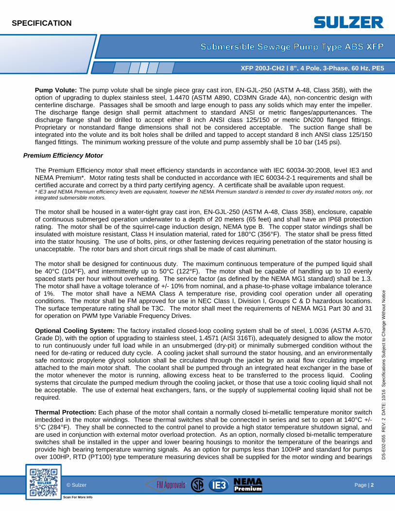
Pump Volute: The pump volute shall be single piece gray cast iron, EN-GJL-250 (ASTM A-48, Class 35B), with the option of upgrading to duplex stainless steel, 1.4470 (ASTM A890, CD3MN Grade 4A), non-concentric design with centerline discharge. Passages shall be smooth and large enough to pass any solids which may enter the impeller. The discharge flange design shall permit attachment to standard ANSI or metric flanges/appurtenances. The discharge flange shall be drilled to accept either 8 inch ANSI class 125/150 or metric DN200 flanged fittings. Proprietary or nonstandard flange dimensions shall not be considered acceptable. The suction flange shall be integrated into the volute and its bolt holes shall be drilled and tapped to accept standard 8 inch ANSI class 125/150 flanged fittings. The minimum working pressure of the volute and pump assembly shall be 10 bar (145 psi).
Premium Efficiency Motor
The Premium Efficiency motor shall meet efficiency standards in accordance with IEC 60034-30:2008, level IE3 and NEMA Premium*. Motor rating tests shall be conducted in accordance with IEC 60034-2-1 requirements and shall be certified accurate and correct by a third party certifying agency. A certificate shall be available upon request. * IE3 and NEMA Premium efficiency levels are equivalent, however the NEMA Premium standard is intended to cover dry installed motors only, not integrated submersible motors. The motor shall be housed in a water-tight gray cast iron, EN-GJL-250 (ASTM A-48, Class 35B), enclosure, capable of continuous submerged operation underwater to a depth of 20 meters (65 feet) and shall have an IP68 protection rating. The motor shall be of the squirrel-cage induction design, NEMA type B. The copper stator windings shall be insulated with moisture resistant, Class H insulation material, rated for 180°C (356°F). The stator shall be press fitted into the stator housing. The use of bolts, pins, or other fastening devices requiring penetration of the stator housing is unacceptable. The rotor bars and short circuit rings shall be made of cast aluminum. The motor shall be designed for continuous duty. The maximum continuous temperature of the pumped liquid shall be 40°C (104°F), and intermittently up to 50°C (122°F). The motor shall be capable of handling up to 10 evenly spaced starts per hour without overheating. The service factor (as defined by the NEMA MG1 standard) shall be 1.3. The motor shall have a voltage tolerance of +/- 10% from nominal, and a phase-to-phase voltage imbalance tolerance of 1%. The motor shall have a NEMA Class A temperature rise, providing cool operation under all operating conditions. The motor shall be FM approved for use in NEC Class I, Division I, Groups C & D hazardous locations. The surface temperature rating shall be T3C. The motor shall meet the requirements of NEMA MG1 Part 30 and 31 for operation on PWM type Variable Frequency Drives. Optional Cooling System: The factory installed closed-loop cooling system shall be of steel, 1.0036 (ASTM A-570, Grade D), with the option of upgrading to stainless steel, 1.4571 (AISI 316Ti), adequately designed to allow the motor to run continuously under full load while in an unsubmerged (dry-pit) or minimally submerged condition without the need for de-rating or reduced duty cycle. A cooling jacket shall surround the stator housing, and an environmentally safe nontoxic propylene glycol solution shall be circulated through the jacket by an axial flow circulating impeller attached to the main motor shaft. The coolant shall be pumped through an integrated heat exchanger in the base of the motor whenever the motor is running, allowing excess heat to be transferred to the process liquid. Cooling systems that circulate the pumped medium through the cooling jacket, or those that use a toxic cooling liquid shall not be acceptable. The use of external heat exchangers, fans, or the supply of supplemental cooling liquid shall not be required. Thermal Protection: Each phase of the motor shall contain a normally closed bi-metallic temperature monitor switch imbedded in the motor windings. These thermal switches shall be connected in series and set to open at 140°C +/- 5°C (284°F). They shall be connected to the control panel to provide a high stator temperature shutdown signal, and are used in conjunction with external motor overload protection. As an option, normally closed bi-metallic temperature switches shall be installed in the upper and lower bearing housings to monitor the temperature of the bearings and provide high bearing temperature warning signals. As an option for pumps less than 100HP and standard for pumps over 100HP, RTD (PT100) type temperature measuring devices shall be supplied for the motor winding and bearings
SPECIFICATION
Page | 3 © Sulzer
Scan For More Info
DS
-E02
-05
5
RE
V:
2
DA
TE
: 10
/16
Spe
cific
atio
ns S
ub
ject
to C
ha
ng
e W
itho
ut
Notic
e
XFP 200J-CH2 | 8”, 4 Pole, 3-Phase, 60 Hz, PE5
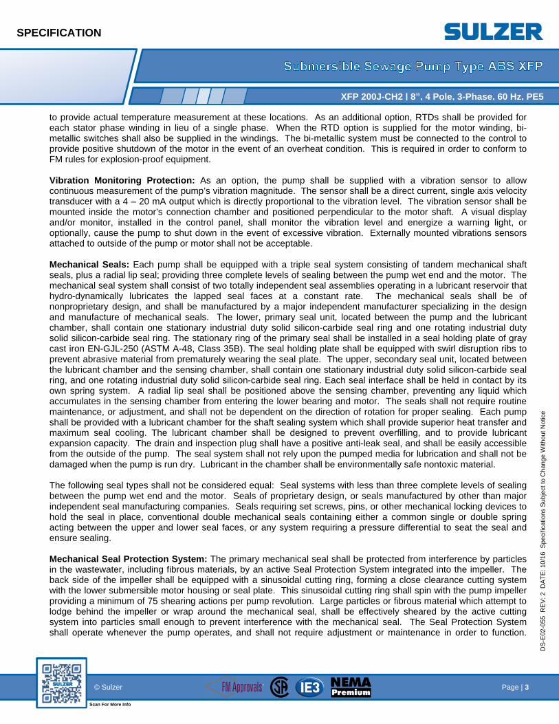
to provide actual temperature measurement at these locations. As an additional option, RTDs shall be provided for each stator phase winding in lieu of a single phase. When the RTD option is supplied for the motor winding, bi-metallic switches shall also be supplied in the windings. The bi-metallic system must be connected to the control to provide positive shutdown of the motor in the event of an overheat condition. This is required in order to conform to FM rules for explosion-proof equipment. Vibration Monitoring Protection: As an option, the pump shall be supplied with a vibration sensor to allow continuous measurement of the pump’s vibration magnitude. The sensor shall be a direct current, single axis velocity transducer with a 4 – 20 mA output which is directly proportional to the vibration level. The vibration sensor shall be mounted inside the motor’s connection chamber and positioned perpendicular to the motor shaft. A visual display and/or monitor, installed in the control panel, shall monitor the vibration level and energize a warning light, or optionally, cause the pump to shut down in the event of excessive vibration. Externally mounted vibrations sensors attached to outside of the pump or motor shall not be acceptable. Mechanical Seals: Each pump shall be equipped with a triple seal system consisting of tandem mechanical shaft seals, plus a radial lip seal; providing three complete levels of sealing between the pump wet end and the motor. The mechanical seal system shall consist of two totally independent seal assemblies operating in a lubricant reservoir that hydro-dynamically lubricates the lapped seal faces at a constant rate. The mechanical seals shall be of nonproprietary design, and shall be manufactured by a major independent manufacturer specializing in the design and manufacture of mechanical seals. The lower, primary seal unit, located between the pump and the lubricant chamber, shall contain one stationary industrial duty solid silicon-carbide seal ring and one rotating industrial duty solid silicon-carbide seal ring. The stationary ring of the primary seal shall be installed in a seal holding plate of gray cast iron EN-GJL-250 (ASTM A-48, Class 35B). The seal holding plate shall be equipped with swirl disruption ribs to prevent abrasive material from prematurely wearing the seal plate. The upper, secondary seal unit, located between the lubricant chamber and the sensing chamber, shall contain one stationary industrial duty solid silicon-carbide seal ring, and one rotating industrial duty solid silicon-carbide seal ring. Each seal interface shall be held in contact by its own spring system. A radial lip seal shall be positioned above the sensing chamber, preventing any liquid which accumulates in the sensing chamber from entering the lower bearing and motor. The seals shall not require routine maintenance, or adjustment, and shall not be dependent on the direction of rotation for proper sealing. Each pump shall be provided with a lubricant chamber for the shaft sealing system which shall provide superior heat transfer and maximum seal cooling. The lubricant chamber shall be designed to prevent overfilling, and to provide lubricant expansion capacity. The drain and inspection plug shall have a positive anti-leak seal, and shall be easily accessible from the outside of the pump. The seal system shall not rely upon the pumped media for lubrication and shall not be damaged when the pump is run dry. Lubricant in the chamber shall be environmentally safe nontoxic material. The following seal types shall not be considered equal: Seal systems with less than three complete levels of sealing between the pump wet end and the motor. Seals of proprietary design, or seals manufactured by other than major independent seal manufacturing companies. Seals requiring set screws, pins, or other mechanical locking devices to hold the seal in place, conventional double mechanical seals containing either a common single or double spring acting between the upper and lower seal faces, or any system requiring a pressure differential to seat the seal and ensure sealing. Mechanical Seal Protection System: The primary mechanical seal shall be protected from interference by particles in the wastewater, including fibrous materials, by an active Seal Protection System integrated into the impeller. The back side of the impeller shall be equipped with a sinusoidal cutting ring, forming a close clearance cutting system with the lower submersible motor housing or seal plate. This sinusoidal cutting ring shall spin with the pump impeller providing a minimum of 75 shearing actions per pump revolution. Large particles or fibrous material which attempt to lodge behind the impeller or wrap around the mechanical seal, shall be effectively sheared by the active cutting system into particles small enough to prevent interference with the mechanical seal. The Seal Protection System shall operate whenever the pump operates, and shall not require adjustment or maintenance in order to function.

SPECIFICATION
Page | 4 © Sulzer
Scan For More Info
DS
-E02
-05
5
RE
V:
2
DA
TE
: 10
/16
Spe
cific
atio
ns S
ub
ject
to C
ha
ng
e W
itho
ut
Notic
e
XFP 200J-CH2 | 8”, 4 Pole, 3-Phase, 60 Hz, PE5
Submersible pump designs which do not incorporate an active cutting system to protect the primary mechanical seal shall not be considered acceptable for wastewater service. Seal Failure Early Warning System: The integrity of the mechanical seal system shall be continuously monitored during pump operation and standby time. An electrical probe shall be provided in a sensing chamber positioned above the mechanical seals for detecting the presence of water contamination within the chamber. The sensing chamber shall be oil-filled, and shall have a drain / inspection plug with a positive anti-leak seal which is easily accessible from the outside of the pump. A solid-state relay mounted in the pump control panel or in a separate enclosure shall send a low voltage, low amperage signal to the probe, continuously monitoring the conductivity of the liquid in the sensing chamber. If sufficient water enters the sensing chamber, the probe shall sense the increase in conductivity and signal the solid state relay in the control panel. The relay shall then energize a warning light on the control panel, or optionally, cause the pump shut down. This system shall provide an early warning of mechanical seal leakage, thereby preventing damage to the submersible motor, and allowing scheduled, rather than emergency, maintenance. Systems utilizing float switches or any other monitoring devices located in the stator housing rather than in a sensing chamber are not considered to be early warning systems, and shall not be considered equal. As an option for pumps less than 100HP and standard for pumps over 100HP, two additional moisture sensing probes, one in the electrical connection chamber, and one in the motor chamber shall be provided. These probes shall send separate signals to the control panel as described above, so that maintenance personnel are given an early warning of the presence of moisture in the respective sensing chambers. Shaft: The pump shaft and motor shaft shall be an integral, one piece unit adequately designed to meet the maximum torque required at any normal start-up condition or operating point in the system. The shaft shall have a full shutoff head design safety factor of 1.7, and the maximum shaft deflection shall not exceed .05 mm (.002 inch) at the lower seal during normal pump operation. Each shaft shall be of stainless steel, 1.4021 (AISI 420), with the option of upgrading to duplex stainless steel, 1.4462 (UNS S31803), and shall have a polished finish with accurately machined shoulders to accommodate bearings, seals and impeller. Carbon steel, chrome plated, or multi-piece welded shafts shall not be considered adequate or equal. Bearings: Each pump shaft shall rotate on high quality, permanently lubricated, greased bearings. The upper bearing shall be a cylindrical roller bearing. As an option, the upper bearing can be electrically isolated from the bearing housing to prevent bearing damage from circulating currents when the pump is operated on a variable frequency drive. The lower bearings shall be a matched set of at least three heavy duty bearings; two angular contact ball bearings and one cylindrical roller bearing. All three lower bearings shall have identical outer race diameters to provide maximum bearing load capacity. Designs which utilize a roller bearing with a smaller outer diameter than the other bearings in the assembly do not provide maximum load capacity and shall not be considered equal. Bearings shall be of sufficient size and properly spaced to transfer all radial and axial loads to the pump housing and minimize shaft deflection. L-10 bearing life shall be a minimum of 100,000 hours at flows ranging from ½ of BEP flow to 1½ times BEP flow (BEP is best efficiency point). The bearings shall be manufactured by a major internationally known manufacturer of high quality bearings, and shall be stamped with the manufacturer’s name and size designation on the race. Generic or unbranded bearings from other than major bearing manufacturers shall not be considered acceptable. Power Cable: The power cables shall be sized according to NEC and CSA standards and shall be of sufficient length to reach the junction box without requiring splices. The outer jacket of the cable shall be of chlorinated polyethylene (CPE) and be oil, water, and UV resistant, capable of continuous submerged operation underwater to a depth of 65 feet. Cable Entry/Junction Chamber: The cable entry design shall not require a specific torque to insure a watertight seal. The cable entry shall consist of cylindrical elastomer grommets, flanked by stainless steel washers. A cable cap incorporating a strain relief and bend radius limiter shall mount to the cable entry boss, compressing the grommet ID

SPECIFICATION
Page | 5 © Sulzer
Scan For More Info
DS
-E02
-05
5
RE
V:
2
DA
TE
: 10
/16
Spe
cific
atio
ns S
ub
ject
to C
ha
ng
e W
itho
ut
Notic
e
XFP 200J-CH2 | 8”, 4 Pole, 3-Phase, 60 Hz, PE5
to the cable while the grommet OD seals against the bore of the cable entry. The junction chamber shall be isolated and sealed from the motor by means of sealing glands. Electrical connections between the power cables and motor leads shall be made via a compression or post type terminal board, allowing for easy disconnection and maintenance.
Accessories Guide Rail Base Assembly (wet pit installation): There shall be no need for personnel to enter the wet well to remove or reinstall the pump(s). In a wet pit installation, the discharge base & elbow assembly shall be permanently installed in the wet well and connected to the discharge piping. In order to prevent binding or separation of the pump from the guide rail system, the pump(s) shall connect to the guide rail base automatically and firmly, guided by one 2 inch guide pipe (two 2 inch pipes optional) extending from the base elbow to the top of the station. Systems using guide cable in lieu of rigid guide bars or pipes shall not be considered acceptable. The sliding guide bracket shall be a separate part of the pumping unit, capable of being attached to standard pump flanges, so that the pump mounting is nonproprietary, and any pump with a standard discharge flange can be mounted on the base assembly. Base or bracket assemblies with proprietary or nonstandard flange dimensions shall not be considered acceptable. A field replaceable Nitrile (Buna-N) rubber profile gasket or O-ring shall accomplish positive sealing of the pump flange/guide rail bracket to the discharge elbow. Base assemblies which rely solely on metal-to-metal contact between the pump flange and discharge base elbow as a means of sealing are inherently leak prone, and shall not be considered equal. No portion of the pump shall bear directly on the floor of the sump. The guide rail system shall be available in an optional non-sparking version, approved by Factory Mutual for use in NEC Class 1, Division 1, Group C&D hazardous locations. Base Assembly (dry-pit installation): In a dry-pit installation, the pump shall be secured to a steel support stand attached to cast concrete support pillars (concrete support pillars supplied by others) of suitable strength to support the weight of the pump and resist any expected torsion, bending, or vibration forces. The pump shall be suitable for either vertical or horizontal dry-pit installation without requiring any internal modifications.


C STAINLESS STEEL CHAIN SUBMITTAL DATA:
ISSUED 6/03
SECTION A
PAGE1
[ ]ENGINEER [ ]APPROVED[ ]CUSTOMER [ ]REJECTED
S.E. REGIONAL WAREHOUSE: ABS PUMPS, INC. www.abspumps.com111 MARITIME DRIVE
SANFORD, FLORIDA 32771PH. (800)323-1731 / (407)330-3456 / FAX.(407)330-3404
ABS reserves the right to change any Data and Dimensions without prior notice and can not be held responsible for the use of this information.
[ ] Type 304 welded steel chain is a general purpose, rustproof product for ordinary wastewater
applications not requiring high strength or extremely corrosive environments.
[ ] Type 316 welded steel chain is a rugged, highly corrosion resistant stainless used in chemical,
water, and wastewater plants worldwide.
CHAIN LENGTH: [ ]1' [ ]1.5' [ ]2' [ ]3' [ ]4' [ ]5' [ ]6' [ ]7' [ ]8' [ ]9' [ ]10' [ ]11' [ ]12' [ ]13' [ ]14' [ ]15' [ ]16' [ ]18' [ ]20' [ ]22' [ ]24' [ ]25' [ ]26' [ ]28' [ ]30' [ ]Other____' TRADE SIZE - WORKING LOAD INCHES - LIMIT (lbs.) - MATERIAL DIA. - INSIDE LGTH. - INSIDE WIDTH -_WT./100'FT 3/16" 1,150 .217 .980 .300 38 # 1/4" 1,860 .275 1.240 .380 61 # 5/16" 2,425 .330 1.290 .440 84 # 3/8" 3,800 .394 1.380 .550 140 # 1/2" 6,425 .512 1.790 .720 234 # 5/8" 9,725 .630 2.200 .790 358 # 3/4" 15,175 .787 2.760 .980 551 #
DO NOT USE FOR OVERHEAD LIFTING
✔✔
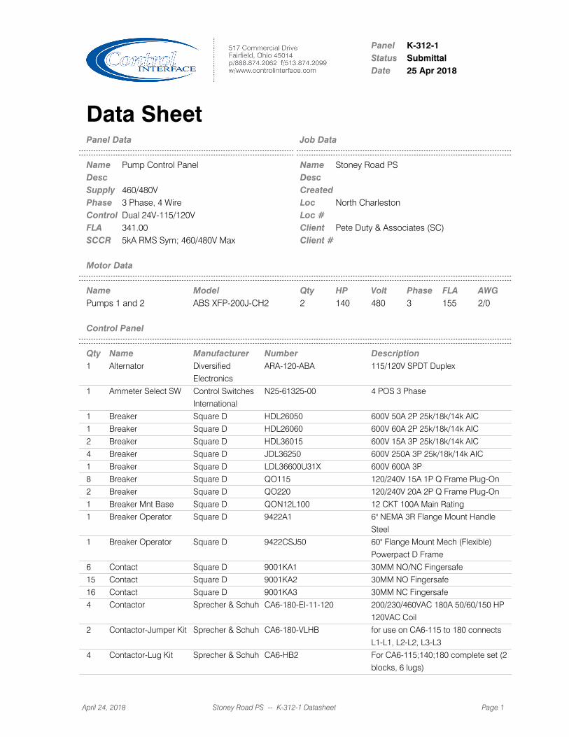
PanelStatusDate
K-312-1Submittal25 Apr 2018
Data SheetPanel Data Job Data
Name NameDesc DescSupply CreatedPhase LocControl Loc #FLA ClientSCCR Client #
Pump Control Panel Stoney Road PS
460/480V3 Phase, 4 Wire North CharlestonDual 24V-115/120V341.00 Pete Duty & Associates (SC)5kA RMS Sym; 460/480V Max
Motor Data
Name Model Qty HP Volt Phase FLA AWGPumps 1 and 2 ABS XFP-200J-CH2 2 140 480 3 155 2/0
Control Panel
Qty Name Manufacturer Number Description1 Alternator Diversified
Electronics
ARA-120-ABA 115/120V SPDT Duplex
1 Ammeter Select SW Control Switches
International
N25-61325-00 4 POS 3 Phase
1 Breaker Square D HDL26050 600V 50A 2P 25k/18k/14k AIC
1 Breaker Square D HDL26060 600V 60A 2P 25k/18k/14k AIC
2 Breaker Square D HDL36015 600V 15A 3P 25k/18k/14k AIC
4 Breaker Square D JDL36250 600V 250A 3P 25k/18k/14k AIC
1 Breaker Square D LDL36600U31X 600V 600A 3P
8 Breaker Square D QO115 120/240V 15A 1P Q Frame Plug-On
2 Breaker Square D QO220 120/240V 20A 2P Q Frame Plug-On
1 Breaker Mnt Base Square D QON12L100 12 CKT 100A Main Rating
1 Breaker Operator Square D 9422A1 6" NEMA 3R Flange Mount Handle
Steel
1 Breaker Operator Square D 9422CSJ50 60" Flange Mount Mech (Flexible)
Powerpact D Frame
6 Contact Square D 9001KA1 30MM NO/NC Fingersafe
15 Contact Square D 9001KA2 30MM NO Fingersafe
16 Contact Square D 9001KA3 30MM NC Fingersafe
4 Contactor Sprecher & Schuh CA6-180-EI-11-120 200/230/460VAC 180A 50/60/150 HP
120VAC Coil
2 Contactor-Jumper Kit Sprecher & Schuh CA6-180-VLHB for use on CA6-115 to 180 connects
L1-L1, L2-L2, L3-L3
4 Contactor-Lug Kit Sprecher & Schuh CA6-HB2 For CA6-115;140;180 complete set (2
blocks, 6 lugs)
April 24, 2018 Stoney Road PS -- K-312-1 Datasheet Page 1

2 Current XFMR Crompton
Instruments
2SFT201 200:5
1 Dist Block Marathon 1453411 600V 840A 3P (2) 600-2 Line (4) 3/0-6
& (4) 4-14 Load
1 Enclosure Hoffman A72XM3EW18FTC 72x118x18 TYPE 12 3 door; flange
disconnect
2 Exhaust Filter Hoffman HG1300404 for HF13 fans
2 Fan/Filter Hoffman HR1616424 120VAC 1PH 0.93A TYPE 12 Top
Mount 348CFM
1 Flasher Ingram Products SSF150W 115/120V 150WATT Inline
1 Floor Stands Hoffman AFK1218 12X18 Steel
3 Fuse Bussman FNQ-1 500V 1A Time-Dly Midget
1 Fuse Bussman FNQ-1/2 500V 0.5A Time-Dly Midget
3 Fuse Bussman FNQ-15 500V 15A Time-Dly Midget
5 Fuse Bussman FNQ-2 500V 2A Time-Dly Midget
2 Fuse Bussman FNQ-R-6 600V 6A Time-Dly Class CC
1 Fuse Bussman KTK-R-10 600V 10A Fast-Act Class CC
9 Fuse Block Marathon 6SM30A1I 600V 30A 1P Midget Rail Mnt Trip Ind
2 Fuse Block Marathon 6SM30A3I 600V 30A 3P Midget Rail Mnt Trip Ind
1 Ground Lug Ilsco AU-2/0 2/0G Double
2 Ground Lug Square D PK7GTA #14-2/0 Ground Bar
1 Inner Door Control Interface 58.75 X 24.625 0.125
ALUM
Inner Door For A72XM3EQ18SSN4
For Door 3
1 Inner Door Control Interface 58.75 X 26.875 0.125
ALUM
Inner Door For A72XM3EQ18SSN4
For Doors 1 And 2
2 Intrinsic Safe Barrier Mercoid MTL7787+ 12-24VDC Zener Barrier
2 Light - Cabinet Nora Lighting NULS-18 115/120V 25-1/8 Direct Wire
2 Light - Pilot Square D 9001SKP38LGG9 115/120V NEMA 4X LED Green
1 Light - Pilot Square D 9001SKP38LLL9 115/120V NEMA 4X LED Blue
4 Light - Pilot Square D 9001SKP38LRR9 115/120V NEMA 4X LED Red
1 Lightning Arrestor Delta Lightning
Arrestors
LA603 600V 3P 3/4W
2 Limit Switch Square D XCKT2910N12 10A 2NC
2 Limit Switch - Arm Square D ZCY45 Adjustable Length w/ Plastic Roller
2 Limit Switch - Head Square D ZCE01 90 Deg Head
2 Line Reactor TCI KDRULH1L 460V 3PH 150HP 3% 180A
2 Mechanical Interlock Sprecher & Schuh CM6-D02 for CA6 contactors
1 Meter - Amp Yokogawa 250340LSRL 200A
1 Meter - Volt Yokogawa YK-250344SJSJ 600V
1 Monitor - Phase/Volt Diversified
Electronics
SUA-440-ASA 460V 3PH 1P Plug In
2 Operator - PB Square D 9001SKR1B 30MM NEMA 4X Black
2 Operator - SW Square D 9001SKS11B 30MM NEMA 4X 2 Pos Cam E
3 Operator - SW Square D 9001SKS46B 30MM NEMA 4X 3 POS Cam F
4 Operator - SW Square D 9001SKS52B 30MM NEMA 4X 3 POS SP-LR Cam B
1 Operator Adapter Hoffman APCSDA Flange Mount Square D 9422
1 PLC - Base Unit Allen Bradley 1766-L32AWA 115/120V Micrologix 1400 20 PT AC
In/12 Relay Out Ethernet
1 PLC - HMI Square D HMIGTO6310 24VDC 12.1IN 4X INDOOR Magelis
Color Touch 96MB, Ethernet, USB,
SD
April 24, 2018 Stoney Road PS -- K-312-1 Datasheet Page 2

3 PLC - I/O Module Allen Bradley 1762-IA8 115/120V 8 PTS Micro Logix Input
Module
2 PLC - I/O Module Allen Bradley 1762-IF4 4 PTS Micrologix 1100/1400 4 In
1 PLC - I/O Module Allen Bradley 1762-OF4 4 PTS Micrologix 1100/1400 4 Out
1 PLC - Network Square D TCSESU053FN0 24VDC 5 PORT Ethernet Switch
10/100BaseT
1 Power Supply Puls CS10.241 24VDC 10A Din Rail Mount
33 Relay Idec RR3B-ULAC120V 115/120V 3P 11 Blade Ind Light
13 Relay Idec RV8H-L-AD110 110-125V AC/DC 1 pole formC
2 Relay - Industrial Square D CAD32G7 115/120V 3 NO/2 NC IEC
1 Relay - Intrinsic Safe Diversified
Electronics
ISO-120-AFA 115/120V 1 CH-SPST w/ Socket
2 Relay - Timer Attach Square D LADR2 115/120V 1 NO/ 1NC IEC Pneumatic
Off Delay 0.1-30 S
1 Socket Custom
Connector
RB08-PC 600V 8-Pin Panel Mount
5 Socket Idec SR2P-06 300V 2P 8 Pin
33 Socket Idec SR3B-05 300V 3P 11 Blade Double Tier
1 Socket Idec SR3P-06 300V 3P 11 Pin
2 Softstart Square D ATS48C21Y 208/230/460V 3PH 60/75/150HP
Altistart 48
2 Softstart - Keypad
Remote Mount Kit
Square D VW3G48101 Altistart 48
3 Surge Suppressor Bussman BSPD24DINLHF 24V 4-20mA 2 pair wires
30 Term Block Square D NSYTRV162 600V 85A 16-4AWG Gray 12mm
34 Term Block Square D NSYTRV42BL 600V 30A 26-10AWG Blue 6mm
5 Term Block Square D NSYTRV42GN 600V 30A 26-10AWG Green 6mm
6 Term Block Square D NSYTRV44 600V 30A 26-10AWG GRAY 2 tier
6.2mm width
18 Term Block Square D NSYTRV62 600V 50A 24-8AWG Gray 8mm
1 Term End Anchor Square D NSYTRAABV35 Gray
1 Term End Barrier Square D NSYTRAC22 Gray For 2.5-10mm TB
1 Term End Barrier Square D NSYTRAC24 Gray for NSYTRV44
2 Thermostat Pfannenburg 17121000010 NO
2 Time Meter Redington
Counters
710-0002 115/120V 99,999.9 Hrs Non-Reset
4 Timer Idec RTE-P1AF20 120/240V 2P 8 Pin On Delay Multi
Function
1 Timer Idec RTE-P2AF20 120/240V 2P 11 Pin Signal Start
On/Off Delay Multi Function
1 Uninterruptable
Power Supply
Sola SDU500 115/120V 500VA
2 VFD - Keypad Allen Bradley 22-HIM-A3 Powerflex400 for use with 22-HIM-B1
2 VFD - Keypad
Remote Mount Kit
Allen Bradley 22-HIM-B1 BEZEL FOR USE WITH 22-HIM-A3 inc
2m cable; standard cat5e will work
2 Variable Frequency
Drive
Allen Bradley 22C-D208A103 480V 208 150HP Powerflex 400
1 Volt Meter Selector
Switch
Control Switches
International
N25-61312-00 4 POS 3 Phase
Remote Mounted
April 24, 2018 Stoney Road PS -- K-312-1 Datasheet Page 3
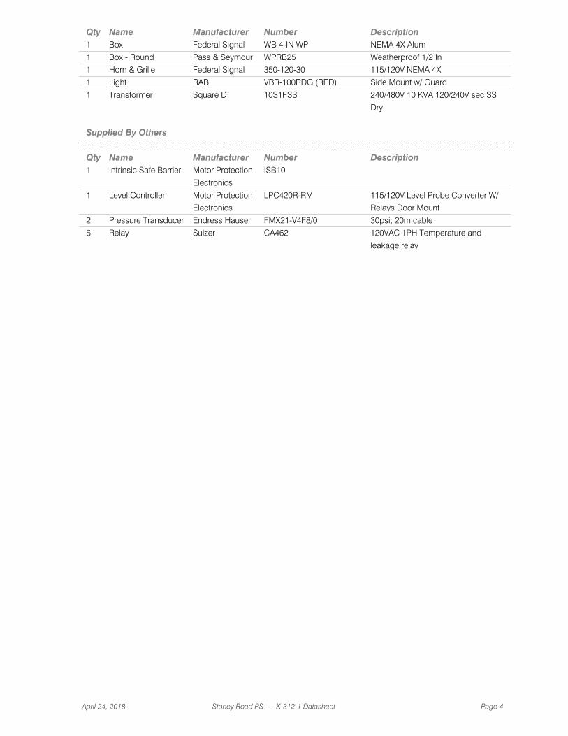
Qty Name Manufacturer Number Description1 Box Federal Signal WB 4-IN WP NEMA 4X Alum
1 Box - Round Pass & Seymour WPRB25 Weatherproof 1/2 In
1 Horn & Grille Federal Signal 350-120-30 115/120V NEMA 4X
1 Light RAB VBR-100RDG (RED) Side Mount w/ Guard
1 Transformer Square D 10S1FSS 240/480V 10 KVA 120/240V sec SS
Dry
Supplied By Others
Qty Name Manufacturer Number Description1 Intrinsic Safe Barrier Motor Protection
Electronics
ISB10
1 Level Controller Motor Protection
Electronics
LPC420R-RM 115/120V Level Probe Converter W/
Relays Door Mount
2 Pressure Transducer Endress Hauser FMX21-V4F8/0 30psi; 20m cable
6 Relay Sulzer CA462 120VAC 1PH Temperature and
leakage relay
April 24, 2018 Stoney Road PS -- K-312-1 Datasheet Page 4

100 128100
to 103,128
101
to 104,128
102
to 104,129
480 VAC3 PhaseService
129
130
131
132
133
134
135
136
137
138
139
140
141
142
143
144
145
146
147
148
149
150
151
152
153
154
155
101
102
103
104
105
106
107
108
109
110
111
112
113
114
115
116
117
118
119
120
121
122
123
124
125
126
127
100from 100
101from 101
102from 102
250A
CB105
DB105
T3
T1
T2
400,428,408
150HP 208APOWERFLEX 400
VFD105T1L1
T2L2
T3L3
PEPE
CN348
410,413,429
150HP 210AATS48C21Y
RVSS109T1L1
T2L2
T3L3
A2
B2
W1
250A
CB109 CN349
250A
CB115
DB115
T3
T1
T2
414,431,422
150HP 208APOWERFLEX 400
VFD115T1L1
T2L2
T3L3
PEPE
CN351
424,427,432
150HP 210AATS48C21Y
RVSS119T1L1
T2L2
T3L3
A2
B2
W1
250A
CB119 CN352
155 FLA140 HP PUMP 2
MTR106
155 FLA140 HP PUMP 3
MTR116
L1150HP, 180A
LR105
T1
L2 T2
L3 T3
L1150HP, 180A
LR115
T1
L2 T2
L3 T3
CT105
CT115
105 105A 105B 105C
106 106A 106B 106C
107 107A 107B 107C
109A
110A
111A
115 115A 115B 115C
116 116A 116B 116C
117 117A 117B 117C
119 119A
120 120A
121 121A
Time Dly
FU14915A
FNQ-15
Time Dly
FU1401A
FNQ-1
PVM140
5
3
4255
LA149
L3
L1
L2
G
50A
CB153153B
to 201
154B
to 202
AM136
AMMETER
CT105
CT105
CT115
1 2
L2L3L1L3
L1L2OFF
SS143
3 6
5
3 8
P2P3
P1OFF
CT SELECT
SS136
11 2
1
VM143
VOLT METER
136 136A
137
138
140
141
142
143 143A
149
150
151
100from 100
101from 101
102from 102
109
110
111
600A
MAIN BREAKER
CB100
15A
CB125
15A
CB129
Macerator
125
Macerator
126
Macerator
127
BioFilter
129
BioFilter
130
BioFilter
131
H110kVAT153
480 120H4
H2
H3
X1
X4
X2
X3
153C
to 200
100
100
100
101
101
101
102
102
102
125
126
127
129
130
131
DB108G
DB118G
Transformer
153
Transformer
154
Transformer
153A
Transformer
154A
Transformer
153C
153
153C
154
DB100
L3
L1
L2
BIOFILTER3.4 FLA
Macerator7.6 FLA
60A
CB153A153A 153B
154A 154B
NOTES
REVISIONS
The information in this document is the property ofControl Interface, Inc. It is not to be copied,
transmitted to others or used without permission fromControl Interface, Inc. Recipient agrees to these
conditions by acceptance of this document.
CLIENT
LOCATION
DRAWN BY CHECKED BY
CLIENT REF
PANEL
JOB
STATUS DATE
CONTROL INTERFACE, INC.517 Commercial DriveFairfield, OH 45014p/888.874.2062 f/513.874.2099www.controlinterface.com
DWG SHEET
North Charleston
K-312
16 Apr 2018Submittal
Pump Control Panel
Stoney Road PS
n/a
n/aC Fox
Pete Duty & Associates (SC)
1
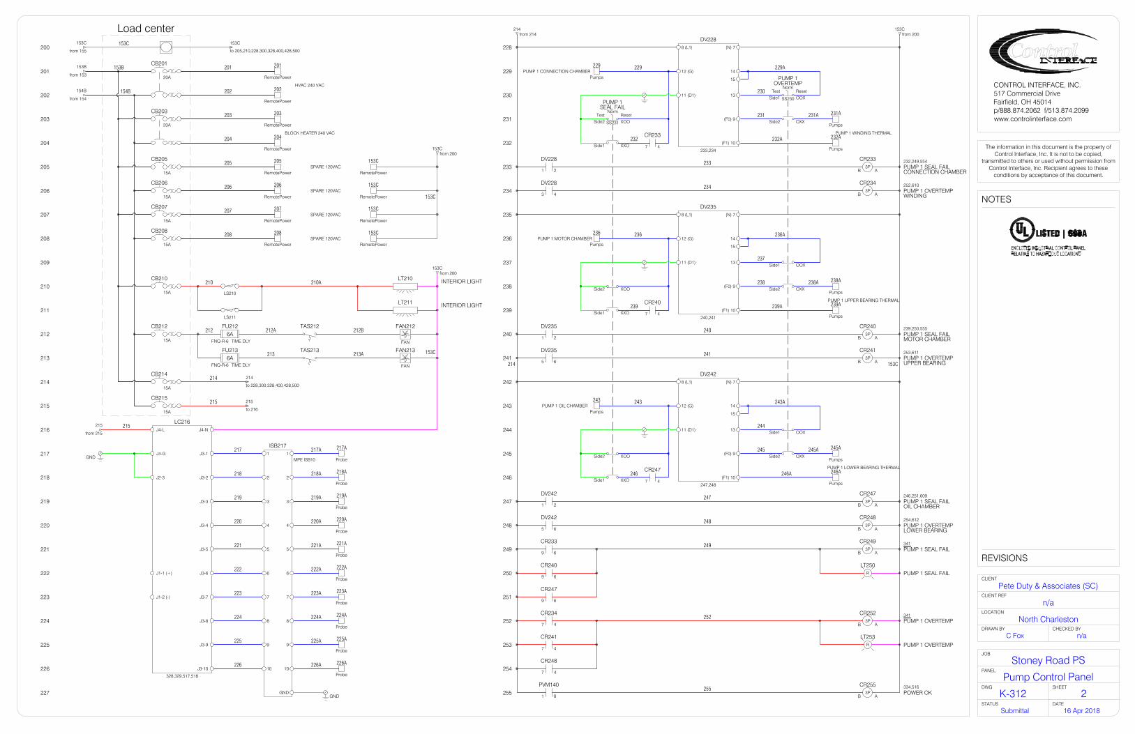
200 228
229
230
231
232
233
234
235
236
237
238
239
240
241
242
243
244
245
246
247
248
249
250
251
252
253
254
255
201
202
203
204
205
206
207
208
209
210
211
212
213
214
215
216
217
218
219
220
221
222
223
224
225
226
227
FAN
FAN212
FAN
FAN213
TAS212
TAS213
TIME DLY
FU2126A
FNQ-R-6
LT210 INTERIOR LIGHT
LT211 INTERIOR LIGHT
LS210
LS211
20A
CB201
20A
CB203
15A
CB207
15A
CB208
15A
CB210
15A
CB212
15A
CB214
15A
CB215
HVAC 240 VAC
RemotePower
201
RemotePower
202
BLOCK HEATER 240 VAC
RemotePower
203
RemotePower
204
SPARE 120VACRemotePower
205
RemotePower
153C
214
to 228,300,328,400,428,500
153C
from 155
Load center153C
to 205,210,228,300,328,400,428,500
153Cfrom 200
J4-L
J4-G
J2-3
J4-N
J3-1
J3-2
J3-3
J3-4
J3-5
J3-6
J3-7
J3-8
J3-9
J3-10
J1-1 (+)
J1-2 (-)
328,329,517,518
LC216
GND Probe
217A
Probe
218A
Probe
219A
Probe
220A
Probe
221A
Probe
222A
Probe
223A
Probe
224A
Probe
225A
Probe
226A
GND
217 217A
218 218A
219 219A
220 220A
221 221A
222 222A
223 223A
224 224A
225 225A
226 226A
2
1
3
4
5
6
7
8
9
10
1
2
3
4
5
6
7
8
9
10
GND
MPE ISB10
ISB217
214from 214
21
DV228
AB CONNECTION CHAMBERPUMP 1 SEAL FAIL
CR2333P
232,249,554
8 (L1)
12 (G)
(N) 7
(F0) 9
(F1) 10
1311 (D1)
15
14
233,234
DV228
ResetOOX
NormTest
OVERTEMPPUMP 1
SS230Side1
OXXSide2
PUMP 1 WINDING THERMAL
Pumps
231A
Pumps
232A
ResetXOO
NormTest
SEAL FAILPUMP 1
SS231Side2
XXOSide1 47
CR233
PUMP 1 CONNECTION CHAMBERPumps
229
21
DV235
AB MOTOR CHAMBERPUMP 1 SEAL FAIL
CR2403P
239,250,555
8 (L1)
12 (G)
(N) 7
(F0) 9
(F1) 10
1311 (D1)
15
14
240,241
DV235
OXXSide2
PUMP 1 UPPER BEARING THERMAL
Pumps
238A
Pumps
239A
XXOSide1 47
CR240
21
DV242
AB OIL CHAMBERPUMP 1 SEAL FAIL
CR2473P
246,251,609
8 (L1)
12 (G)
(N) 7
(F0) 9
(F1) 10
1311 (D1)
15
14
247,248
DV242
OXXSide2
PUMP 1 LOWER BEARING THERMAL
Pumps
245A
Pumps
246A
XXOSide1 47
CR247
PUMP 1 OIL CHAMBERPumps
243
43
DV228
AB WINDINGPUMP 1 OVERTEMP
CR2343P
252,610
65
DV235
AB UPPER BEARINGPUMP 1 OVERTEMP
CR2413P
253,611
65
DV242
AB LOWER BEARINGPUMP 1 OVERTEMP
CR2483P
254,612
69
CR233
69
CR240
69
CR247
47
CR234
47
CR241
47
CR248
ABPUMP 1 SEAL FAIL
CR2493P
341
ABPUMP 1 OVERTEMP
CR2523P
341
PUMP 1 SEAL FAILLT250
R
PUMP 1 OVERTEMPLT253
R
XOOSide2
XOOSide2
OOXSide1
OOXSide1
PUMP 1 MOTOR CHAMBERPumps
236
ABPOWER OK
CR2553P
334,516
81
PVM140
153C
210 210A
212 212A 212B
213A
214
214
215
229 229A
230
231 231A
232 232A
233
234
236 236A
237
238 238A
239 239A
240
241
243 243A
244
245 245A
246 246A
247
248
249
252
255
153C
TIME DLY
FU2136A
FNQ-R-6
213
SPARE 120VACRemotePower
206
RemotePower
153C
201
202
203
204
153Cfrom 200
SPARE 120VACRemotePower
207
RemotePower
153C
SPARE 120VACRemotePower
208
RemotePower
153C
207
208
15A
CB205
15A
CB206
153B
from 153
154B
from 154
153Cfrom 200
153C
153C
215
to 216
215
from 215
215
153B
154B
205
206
NOTES
REVISIONS
The information in this document is the property ofControl Interface, Inc. It is not to be copied,
transmitted to others or used without permission fromControl Interface, Inc. Recipient agrees to these
conditions by acceptance of this document.
CLIENT
LOCATION
DRAWN BY CHECKED BY
CLIENT REF
PANEL
JOB
STATUS DATE
CONTROL INTERFACE, INC.517 Commercial DriveFairfield, OH 45014p/888.874.2062 f/513.874.2099www.controlinterface.com
DWG SHEET
North Charleston
K-312
16 Apr 2018Submittal
Pump Control Panel
Stoney Road PS
n/a
n/aC Fox
Pete Duty & Associates (SC)
2

300 328
329
330
331
332
333
334
335
336
337
338
339
340
341
342
343
344
345
346
347
348
349
350
351
352
353
354
355
301
302
303
304
305
306
307
308
309
310
311
312
313
314
315
316
317
318
319
320
321
322
323
324
325
326
327
214from 214
153Cfrom 200
214from 214
153Cfrom 200
21
DV300
AB CONNECTION CHAMBERPUMP 2 SEAL FAIL
CR3053P
304,321,606
8 (L1)
12 (G)
(N) 7
(F0) 9
(F1) 10
1311 (D1)
15
14
305,306
DV300
ResetOOX
NormTest
OVERTEMPPUMP 2
SS302Side1
OXXSide2
PUMP 2 WINDING THERMAL
Pumps
303A
Pumps
304A
ResetXOO
NormTest
SEAL FAILPUMP 2
SS303Side2
XXOSide1 47
CR305
PUMP 2 CONNECTION CHAMBERPumps
301
21
DV307
AB MOTOR CHAMBERPUMP 2 SEAL FAIL
CR3123P
311,322,607
8 (L1)
12 (G)
(N) 7
(F0) 9
(F1) 10
1311 (D1)
15
14
312,313
DV307
OXXSide2
PUMP 2 UPPER BEARING THERMAL
Pumps
310A
Pumps
311A
XXOSide1 47
CR312
21
DV314
AB OIL CHAMBERPUMP 2 SEAL FAIL
CR3193P
318,323,613
8 (L1)
12 (G)
(N) 7
(F0) 9
(F1) 10
1311 (D1)
15
14
319,320
DV314
OXXSide2
PUMP 2 LOWER BEARING THERMAL
Pumps
317A
Pumps
318A
XXOSide1 47
CR319
PUMP 2 OIL CHAMBERPumps
315
43
DV300
AB WINDINGPUMP 2 OVERTEMP
CR3063P
324,614
65
DV307
AB UPPER BEARINGPUMP 2 OVERTEMP
CR3133P
325,615
65
DV314
AB LOWER BEARINGPUMP 2 OVERTEMP
CR3203P
326,616
69
CR305
69
CR312
69
CR319
47
CR306
47
CR313
47
CR320
ABPUMP 2 SEAL FAIL
CR3213P
344
ABPUMP 2 OVERTEMP
CR3243P
344
PUMP 2 SEAL FAILLT322
R
PUMP 2 OVERTEMPLT325
R
XOOSide2
XOOSide2
OOXSide1
OOXSide1
PUMP 2 MOTOR CHAMBERPumps
308
ABHIGH HIGH LEVEL
CR3293P
330,332,535
2019RLY 1
LC216
47
CR329
AB BYPASS MODEEMERGENCY
CR3303P
331,332,520
ON DELAY27
336
CALL FOR LAGEMERGENCY BYPASS
TD3342P
47
CR330
17
CR RESETEMERGENCY BYPASS
PB331
69
CR330
69
CR329
8 6
TD334
1 3
TD332
47
CR255
AB START PUMP 1EMERGENCY BYPASS
CR3353P
343
AB START PUMP 2EMERGENCY BYPASS
CR3373P
346
OXOSIDE1
EA33821
85
34
SIDE2 OOXSS335
LEAD SELECTP2
ALT
XOOP3
AutoXOO
OffMan
PUMP 1 HOA
SS341 OOXSIDE2
AutoXOO
OffMan
PUMP 2 HOA
SS344 OOXSIDE2
17
CR249
17
CR321
47
CR536
47
CR537
47
CR335
47
CR337
5857
CR341
5857
CR344
A2A1
105,401
CONTACTORPUMP 1 VFD
CN348
A2A1
115,415
CONTACTORPUMP 2 VFD
CN351
RVSSXO
VFD
553
PUMP 1 STARTER SELECT
SS348SIDE2 OX A2A1
109,412
CONTACTORPUMP 1 RVSS
CN349
A2A1
119,426
CONTACTORPUMP 2 RVSS
CN352
RVSSXO
VFD
605
PUMP 2 STARTER SELECT
SS351SIDE2 OX
8 6
TD332
ON DELAY27
355
BYPASS MODEEMERGENCY
TD3312P
21RLY 10
LC216
ABLOW LOW LEVEL PROBE
CR3283P
332,534
47
CR328
1 3
TD331
102350,353,348,351EBC OFF DELAY
TD354
2P5
6
41
TD354
811
TD354
A2A1PUMP 2 START
CR3447P
351,415,426
A2A1PUMP 1 START
CR3417P
348,401,412
ON DELAY27
333,334
CALL FOR LEADEMERGENCY BYPASS
TD3322P
17
CR252
17
CR324
CONTROL POWER ONLT327
B
31
TD354
911
TD354
153C
153C
214
214
301 301A
302
303 303A
304 304A
305
306
308 308A
309
310 310A
311 311A
312
313
315 315A
316
317 317A
318 318A
319
320
321
324
328
329
330
331 331A
332 332A 332B
334 334A
335
336
338
341 341A 341B
342
344 344A 344B
345
348 348A 348B
349
351 351A 351B
352
355
355A
INTERLOCKELECTRICAL / MECHANICAL
DV348122121
222221349A
348C
INTERLOCKELECTRICAL / MECHANICAL
DV351122121
222221352A
351C
NOTES
REVISIONS
The information in this document is the property ofControl Interface, Inc. It is not to be copied,
transmitted to others or used without permission fromControl Interface, Inc. Recipient agrees to these
conditions by acceptance of this document.
CLIENT
LOCATION
DRAWN BY CHECKED BY
CLIENT REF
PANEL
JOB
STATUS DATE
CONTROL INTERFACE, INC.517 Commercial DriveFairfield, OH 45014p/888.874.2062 f/513.874.2099www.controlinterface.com
DWG SHEET
North Charleston
K-312
16 Apr 2018Submittal
Pump Control Panel
Stoney Road PS
n/a
n/aC Fox
Pete Duty & Associates (SC)
3
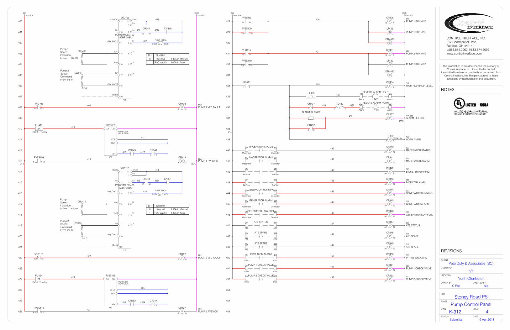
400 428
429
430
431
432
433
434
435
436
437
438
439
440
441
442
443
444
445
446
447
448
449
450
451
452
453
454
455
401
402
403
404
405
406
407
408
409
410
411
412
413
414
415
416
417
418
419
420
421
422
423
424
425
426
427
214from 214
153Cfrom 200
11
1
2
5
6
7
8
11
13
14
17
18
15
16
20
+24VDC
Run
+10VDC
Ai1
Anlg Com 1
Ai2
Anlg Com 2
Ao1
Ao2
Stop
Di1
Di2
Di3
Di4
Shield
150HP 208APOWERFLEX 400
VFD105
105
OOX
PUMP 1 HOA
SS341SIDE2
4443
CR341 CN348
Di1 Spd Ref0 Keypad1 PLC via Ai1
-HOA in ManualHOA in Auto
628,629
CBL403
Time Dly
FU4102A
FNQ-2
43
CR341CN349
ABPUMP 1 RVSS OK
CR4133P
551
Time Dly
FU4242A
FNQ-2
43
CR344CN352
ABPUMP 2 RVSS OK
CR4273P
603119
150HP 210AATS48C21Y
RVSS119CL1 CL2
STOP
RUN
+24
109
150HP 210AATS48C21Y
RVSS109CL1 CL2
STOP
RUN
+24
ABPUMP 1 VFD FAULT
CR4083P
552
ABPUMP 2 VFD FAULT
CR4223P
604
R3R2
VFD105
R3R2
VFD115
R1CR1A
RVSS109
R1CR1A
RVSS119
408
410
411
412 412A
413
422
424
425
426 426A
427
11
1
2
5
6
7
8
11
13
14
17
18
15
16
20
+24VDC
Run
+10VDC
Ai1
Anlg Com 1
Ai2
Anlg Com 2
Ao1
Ao2
Stop
Di1
Di2
Di3
Di4
Shield
150HP 208APOWERFLEX 400
VFD115
115
4443
CR344 CN351
Di1 Spd Ref0 Keypad1 PLC via Ai1
-HOA in ManualHOA in Auto
630,631
CBL417
OOX
PUMP 2 HOA
SS344SIDE2
214from 214
153Cfrom 200
ABPUMP 1 RUNNING
CR4283P
548
R4R5
VFD105
PUMP 1 RUNNINGLT429
G
PUMP 2 RUNNINGLT432
G
ABPUMP 2 RUNNING
CR4313P
600
123
ETM430
123
ETM433
R4R5
VFD115
R3CR3A
RVSS119
34
ISR511
ABHIGH HIGH HIGH LEVEL
CR4343P
519
Alarm
435
Alarm
153C
Alarm
436A
Alarm
153C
17
CR437
69
CR437
ABALARM SILENCE
CR4373P
438,436
ALARM SILENCE
PB437
FL435
LT435
REMOTE ALARM LIGHT
HN436
REMOTE ALARM HORN
ON DELAY27
436HORN TIMER
TD4392P
4
TD439
1
428
431
434
435
436 436A
437
R3CR3A
RVSS109
A2A1MACERATOR STATUS
CR4401P
523
A2A1MACERATOR ALARM
CR4411P
524
A2A1GENERATOR RUNNING
CR4441P
527
A2A1GENERATOR ALARM
CR4451P
528
A2A1GENERATOR LOW FUEL
CR4461P
529
A2A1ATS STATUS
CR4471P
530
A2A1ATS SPARE
CR4481P
531
A2A1ATS SPARE
CR4491P
532
A2A1INTRUSION ALARM
CR4501P
533
Macerator
214
Macerator
440
Macerator
214
Macerator
441
Generator
214
Generator
444
Generator
214
Generator
445
Generator
214
Generator
446
ATS
214
ATS
447
ATS
214
ATS
448
ATS
214
ATS
449
MACERATOR STATUS
MACERATOR ALARM
GENERATOR RUNNING
GENERATOR ALARM
GENERATOR LOW FUEL
ATS STATUS
ATS SPARE
ATS SPARE
misc
214
misc
450INTRUSION ALARM
A2A1PUMP 1 CHECK VALVE
CR4511P
550
misc
214
misc
451PUMP 1 CHECK VALVE
A2A1PUMP 2 CHECK VALVE
CR4521P
602
misc
214
misc
452PUMP 2 CHECK VALVE
648
CBL648
SHLD
650
CBL650
SHLD
Pump 2SpeedCommandFrom line
Pump 2SpeedCommandFrom line
Pump 1SpeedIndicationto line
Pump 1SpeedIndicationto line
153C214
400
401 401A
402
414
415 415A
416
153C
440
441
444
445
446
447
448
449
450
451
452
A2A1BIOFILTER RUNNING
CR4421P
525
A2A1BIOFILTER ALARM
CR4431P
526
BioFilter
214
BioFilter
442
BioFilter
214
BioFilter
443
442
443
214
NOTES
REVISIONS
The information in this document is the property ofControl Interface, Inc. It is not to be copied,
transmitted to others or used without permission fromControl Interface, Inc. Recipient agrees to these
conditions by acceptance of this document.
CLIENT
LOCATION
DRAWN BY CHECKED BY
CLIENT REF
PANEL
JOB
STATUS DATE
CONTROL INTERFACE, INC.517 Commercial DriveFairfield, OH 45014p/888.874.2062 f/513.874.2099www.controlinterface.com
DWG SHEET
North Charleston
K-312
16 Apr 2018Submittal
Pump Control Panel
Stoney Road PS
n/a
n/aC Fox
Pete Duty & Associates (SC)
4

500 528
529
530
531
532
533
534
535
536
537
538
539
540
541
542
543
544
545
546
547
548
549
550
551
552
553
554
555
501
502
503
504
505
506
507
508
509
510
511
512
513
514
515
516
517
518
519
520
521
522
523
524
525
526
527
214from 214
153Cfrom 200
434
ISR5115 6
8
1
Float
512
Float
512AHIGH HIGH HIGH FLOAT
FS512
Time Dly
FU5152A
FNQ-2
L
G
N
120VAC 516,523,528,536
MicroLogix 14001766-L32AWAPLC515
Base Unit Power
69POWER OK
CR255
43RLY 9
LC216
1817RLY 2
LC216
47HIGH HIGH HIGH LEVEL
CR434
58EMERGENCY
CR330
LEAD SELECT
SS335
SIDE2 XOO
OOX
512 512A
516
517
518
519
520
521
522
I0 COM0
I1
I2
I3
I4
I5
I6
COM1
PLC515
MODULE 0
515
1411MACERATOR STATUS
CR440
1411MACERATOR ALARM
CR441
1411BIOFILTER RUNNING
CR442
1411BIOFILTER ALARM
CR443
1411GENERATOR ALARM
CR445
1411GENERATOR LOW FUEL
CR446
1411ATS STATUS
CR447
1411ATS SPARE
CR448
1411ATS SPARE
CR449
1411INTRUSION ALARM
CR450
VAC0 O0
O1
O2
O3
O4
O5
O6
O7
RELAYOUTPUT
VAC1
VAC2
VAC3
VAC4
VAC5
O8
O9
VAC6
O10
O11
PLC515
ABPUMP 1 START
CR5363P
342
ABPUMP 2 START
CR5373P
345
ABEBC RESET
CR5383P
536
537
538
69LOW LOW LEVEL PROBE
CR328
58HIGH HIGH LEVEL
CR329
501from 527
501Afrom 527
47PUMP 1 RUNNING
CR428
OOX
PUMP 1 HOA
SS341SIDE1
IN0
IN1
IN2
IN3
IN4
IN5
IN6
IN7 ACCOM
PLC548
1762-IA8MODULE 1
Pump 1 Running
Pump 1 in Auto
Pump 1 Check Valve
Pump 1 RVSS Fail
Pump 1 VFD Fail
Pump 1 on VFD
Pump 1 Seal FailConnection Chamber
Pump 1 Seal FailMotor Chamber
1411PUMP 1 CHECK VALVE
CR451
47PUMP 1 VFD FAULT
CR408
XO
PUMP 1 STARTER SELECT
SS348SIDE2
PUMP 1 RVSS OK17
CR413
58PUMP 1 SEAL FAIL
CR233
58PUMP 1 SEAL FAIL
CR240
523
524
548
549
550
551
552
553
OUTPUT
INPUT
UPS500NL
NL
IN G OUT G
I7
I8 COM2
I9
I10
I11
PLC515
I12 COM3
I13
I14
I15
I16
I17
I18
I19
PLC515
501 501A
501Ato 528,600
501to 528,600
153C214
501
501A
554
5551411
GENERATOR RUNNING
CR444
535
534
533
532
531
530
529
528
527
526
525
NOTES
REVISIONS
The information in this document is the property ofControl Interface, Inc. It is not to be copied,
transmitted to others or used without permission fromControl Interface, Inc. Recipient agrees to these
conditions by acceptance of this document.
CLIENT
LOCATION
DRAWN BY CHECKED BY
CLIENT REF
PANEL
JOB
STATUS DATE
CONTROL INTERFACE, INC.517 Commercial DriveFairfield, OH 45014p/888.874.2062 f/513.874.2099www.controlinterface.com
DWG SHEET
North Charleston
K-312
16 Apr 2018Submittal
Pump Control Panel
Stoney Road PS
n/a
n/aC Fox
Pete Duty & Associates (SC)
5
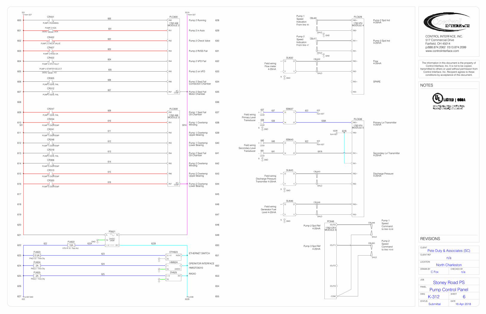
600 628
629
630
631
632
633
634
635
636
637
638
639
640
641
642
643
644
645
646
647
648
649
650
651
652
653
654
655
601
602
603
604
605
606
607
608
609
610
611
612
613
614
615
616
617
618
619
620
621
622
623
624
625
626
627
Time Dly
FU6242A
FNQ-2 24VDC HMIGTO6310
OPERATOR INTERFACEHMI624-+
G
624
47PUMP 2 RUNNING
CR431
OOX
PUMP 2 HOA
SS344SIDE2
1411PUMP 2 CHECK VALVE
CR452
47PUMP 2 VFD FAULT
CR422
XO
PUMP 2 STARTER SELECT
SS351SIDE2
IN0
IN1
IN2
IN3
IN4
IN5
IN6
IN7 ACCOM
PLC600
1762-IA8MODULE 2
Pump 2 Running
Pump 2 in Auto
Pump 2 Check Valve
Pump 2 RVSS Fail
Pump 2 VFD Fail
Pump 2 on VFD
Pump 2 Seal FailConnection Chamber
Pump 2 Seal FailMotor Chamber
IN0
IN1
IN2
IN3
IN4
IN5
IN6
IN7 ACCOM
PLC609
1762-IA8MODULE 3
Pump 1 Seal FailOil Chamber
Pump 1 OvertempWinding
Pump 1 OvertempUpper Bearing
Pump 1 OvertempLower Bearing
Pump 2 Seal FailOil Chamber
Pump 2 OvertempWinding
Pump 2 OvertempUpper Bearing
Pump 2 OvertempLower Bearing
PUMP 2 RVSS OK17
CR427
58PUMP 1 SEAL FAIL
CR247
69PUMP 1 OVERTEMP
CR234
69PUMP 1 OVERTEMP
CR241
69PUMP 1 OVERTEMP
CR248
58PUMP 2 SEAL FAIL
CR319
58PUMP 2 SEAL FAIL
CR305
58PUMP 2 SEAL FAIL
CR312
69PUMP 2 OVERTEMP
CR306
69PUMP 2 OVERTEMP
CR313
69PUMP 2 OVERTEMP
CR320
501from 527
501Afrom 527
24VDC
PS621NL
0V+V
240WGGND
ETHERNET SWITCHETH623N/0VL/+V
GTime Dly
FU6230.5A
FNQ-1/2
623
622to 637,640
622Bto 639
622 622B
IN0+
IN0-
IN1+
IN1-
IN2+
IN2-
IN3+
IN3-
Pump 3 Spd Ind4-20mA
Flow 4-20mA
PLC628Pump 2 Spd Ind4-20mA
SPARE
1762-IF4MODULE 4
IOUT1
IOUT2
IOUT0
COM
IOUT3
PC648
1762-OF4MODULE 6
403
CBL403
SHLD
417
CBL417
SHLD
GND
GND
622B
from 627
622
from 627
622
from 627
GND
CBL632
SHLD
CBL643
SHLD
405,406
CBL648
SHLD
419,420
CBL650
SHLD
Pump 2 Spd Ref4-20mA
Pump 3 Spd Ref4-20mA
+
-
s
+
-
s
+
-
+
-
s
Field wiringFlow meter
4-20mA
Field wiringPrimary Level
Transducer
Field wiringSecondary Level
Transducer
Field wiringDischarge PressureTransmitter 4-20mA
638A
622B
641A
SU64322
11
SU63222
11
622
622ISB637
13
24
ISB64013
24
Level
637
Level
638
Level
640
Level
641
GND
GND
637
638
640
641
GND
CBL646
SHLD
+
-
s
Field wiringGenerator FuelLevel 4-20mA
SU64622
11
GND
IN0+
IN0-
IN1+
IN1-
IN2+
IN2-
IN3+
IN3-
Secondary Lvl Transmitter4-20mA
Discharge Pressure4-20mA
PLC638Primary Lvl Transmitter4-20mA1762-IF4
MODULE 5
s
Pump 1SpeedIndicationFrom line
Pump 2SpeedIndicationFrom line
Pump 1SpeedCommandto line
Pump 2SpeedCommandto line
600
601
602
603
604
605
606
607
609
610
611
612
613
614
615
616
501 501A
RADIODV6250V+V
GTime Dly
FU6252A
FNQ-2
Fast Act
FU62210A
KTK-R-10
622A
625
NOTES
REVISIONS
The information in this document is the property ofControl Interface, Inc. It is not to be copied,
transmitted to others or used without permission fromControl Interface, Inc. Recipient agrees to these
conditions by acceptance of this document.
CLIENT
LOCATION
DRAWN BY CHECKED BY
CLIENT REF
PANEL
JOB
STATUS DATE
CONTROL INTERFACE, INC.517 Commercial DriveFairfield, OH 45014p/888.874.2062 f/513.874.2099www.controlinterface.com
DWG SHEET
North Charleston
K-312
16 Apr 2018Submittal
Pump Control Panel
Stoney Road PS
n/a
n/aC Fox
Pete Duty & Associates (SC)
6

EthSw
Network Map
PLC
EthSw-PLC
HMI
EthSw-HMI
IP: 10.0.0.201
MASK: 255.255.255.0
IP: 10.0.0.202
MASK: 255.255.255.0
SCADA
EthSw-Rad
IP: 10.0.0.xxx
MASK: 255.255.255.0
TD332
TD334
CR341
CR344
TD331
TD354
TD442
Tag Initital Setting Function
90s
Normal to EBC forced RVSS delay
EBC lead start delay
EBC lag delay
EBC to Normal, RVSS to VFD delay
Horn timer
Timers TD331 and TD354 should be set longer thanthe pneumatic timers (CR341 & 344) but less thantimer TD332.
VFD/RVSS Ramp down time. Set longerthan the respective device parameters
30s
90s
30s
5s
25s
Timer Settings
641
-
SECO
NDAR
Y TR
ANSD
UCER
640
+
SECO
NDAR
YY T
RANS
DUCE
R
638
-
PRIM
ARY
TRAN
SDUC
ER
637
+
PRIM
ARY
TRAN
SDUC
ER
308
PUM
P 2
MOT
OR C
HAM
BER
315
PUM
P 2
OIL
CHAM
BER
318A
PUM
P 2
LOW
ER B
EARI
NG T
HERM
AL
317A
PUM
P 2
LOW
ER B
EARI
NG T
HERM
AL
311A
PUM
P 2
UPPE
R BE
ARIN
G TH
ERM
AL
310A
PUM
P 2
UPPE
R BE
ARIN
G TH
ERM
AL
301
PUM
P 2
CONN
ECTI
ON C
HAM
BER
304A
PUM
P 2
WIN
DING
THE
RMAL
303A
PUM
P 2
WIN
DING
THE
RMAL
236
PUM
P 1
MOT
OR C
HAM
BER
243
PUM
P 1
OIL
CHAM
BER
246A
PUM
P 1
LOW
ER B
EARI
NG T
HERM
AL
245A
PUM
P 1
LOW
ER B
EARI
NG T
HERM
AL
239A
PUM
P 1
UPPE
R BE
ARIN
G TH
ERM
AL
238A
PUM
P 1
UPPE
R BE
ARIN
G TH
ERM
AL
229
PUM
P 1
CONN
ECTI
ON C
HAM
BER
232A
PUM
P 1
WIN
DING
THE
RMAL
231A
PUM
P 1
WIN
DING
THE
RMAL
129
BIOF
ILTE
R 48
0VAC
3PH
130
BIOF
ILTE
R 48
0VAC
3PH
131
BIOF
ILTE
R 48
0VAC
3PH
125
MAC
ERAT
OR 4
80VA
C 3P
H
126
MAC
ERAT
OR 4
80VA
C 3P
H
127
MAC
ERAT
OR 4
80VA
C 3P
H
153
H1
TRAN
SFOR
MER
480
VAC
154
H4
TRAN
SFOR
MER
480
VAC
154A
X2/3
TRAN
SFOR
MER
SEC
ONDA
RY
153A
X1
TRAN
SFOR
MER
SEC
ONDA
RY
153C
X4
TRAN
SFOR
MER
SEC
ONDA
RY
201
L1
HVAC
240
VAC
202
L2
HVAC
240
VAC
203
L1
BLOC
K HE
ATER
240
VAC
204
L2
BLOC
K HE
ATER
240
VAC
205
L
SPAR
E 12
0VAC
153C
N
SPAR
E 12
0VAC
206
L
SPAR
E 12
0VAC
153C
N
SPAR
E 12
0VAC
207
LSP
ARE
120V
AC
153C
N
SPAR
E 12
0VAC
208
L
SPAR
E 12
0VAC
153C
N
SPAR
E 12
0VAC
Level Digital signals in from equipmentAlarm
Power out to equipmentTo/from transformerSignals from pump sensors
2
SU500
1
2 1
2
SU503
1
2 1
2
SU506
1
2 1
SUBM
ERIS
BLE
SHIELDS
GN
DG
ND
GN
D
LEVE
L TR
ANSD
UCER
DISC
HARG
EFL
OW
DISC
HARG
EPR
ESSU
RE
+ - + - + -
Analog signals in from equipment
512
HIGH
HIG
H HI
GH F
LOAT
512A
HIGH
HIG
H HI
GH F
LOAT
226A
PROB
E 10
225A
PROB
E 9
224A
PROB
E 8
223A
PROB
E 7
222A
PROB
E 6
221A
PROB
E 5
220A
PROB
E 4
219A
PROB
E 3
218A
PROB
E 1
217A
PROB
E 1
435
ALAR
M L
IGHT
153B
ALAR
M L
IGHT
436A
ALAR
M H
ORN
153B
ALAR
M H
ORN
214
MAC
ERAT
OR S
TATU
S
440
MAC
ERAT
OR S
TATU
S
214
MAC
ERAT
OR A
LARM
441
MAC
ERAT
OR A
LARM
214
BIOF
ILTE
R RU
NNIN
G
442
BIOF
ILTE
R RU
NNIN
G
214
BIOF
ILTE
R AL
ARM
443
BIOF
ILTE
R AL
ARM
214
GENE
RATO
R RU
NNIN
G
444
GENE
RATO
R RU
NNIN
G
214
GENE
RATO
R AL
ARM
1
445
GENE
RATO
R AL
ARM
1
214
GENE
RATO
R LO
W F
UEL
446
GENE
RATO
R LO
W F
UEL
214
ATS
STAT
US
447
ATS
STAT
US
214
ATS
SPAR
E
448
ATS
SPAR
E
214
ATS
SPAR
E
449
ATS
SPAR
E
214
INTR
USIO
N AL
ARM
450
INTR
USIO
N AL
ARM
214
PUM
P 1
CHEC
K VA
LVE
451
PUM
P 1
CHEC
K VA
LVE
214
PUM
P 2
CHEC
K VA
LVE
452
PUM
P 2
CHEC
K VA
LVE
NOTES
REVISIONS
The information in this document is the property ofControl Interface, Inc. It is not to be copied,
transmitted to others or used without permission fromControl Interface, Inc. Recipient agrees to these
conditions by acceptance of this document.
CLIENT
LOCATION
DRAWN BY CHECKED BY
CLIENT REF
PANEL
JOB
STATUS DATE
CONTROL INTERFACE, INC.517 Commercial DriveFairfield, OH 45014p/888.874.2062 f/513.874.2099www.controlinterface.com
DWG SHEET
North Charleston
K-312
16 Apr 2018Submittal
Pump Control Panel
Stoney Road PS
n/a
n/aC Fox
Pete Duty & Associates (SC)
7

EA
338
DV2
28
DV2
35
DV2
42
DV3
00
DV3
07
DV3
14
CR
341
CR
344
CB153 CB125 CB129
CB105
250A
CB109
250A
CB115
250A
CB119
250A
CB100
RVSS109 RVSS119
VFD105 VFD115
LR105 LR115
ISB217
ISR
511
ISB
637
ISB
640
LA14
9
15A
15A
15A
15A
15A
15A
CB203
CB201
SU
632
SU
643
SU
646
FL435
PVM140
ETH
623
TD33
1
TD33
2
TD33
4
TD43
9
CR
233
CR
234
CR
240
CR
241
CR
247
CR
248
CR
249
CR
252
CR
255
CR
305
CR
306
CR
312
CR
313
CR
319
CR
320
CR
321
CR
324
CR
328
CR
329
CR
330
CR
335
CR
337
CR
408
CR
413
CR
422
CR
427
CR
428
CR
431
CR
434
CR
437
CR
536
CR
537
CR
538
FU14
0
FU14
9
CT105 CT115
PLC515
PLC
548
PLC
600
PLC
609
PLC
628
PLC
638
PC
648
TD35
4
SUB-PANEL LAYOUT
Panel: A72PM40 (60"H x 33.75"W)
SUB-PANEL LAYOUT
Panel: A72PM78 (60"H x 72"W
CN348 CN349 CN351 CN352
PS
621
DV6
25
UPS500
TAS212 TAS213
CB153A
15A
DB
100
15A
CR
440
CR
441
CR
442
CR
443
CR
444
CR
445
CR
446
CR
447
CR
448
CR
449
CR
450
CR
451
CR
452
Barrier
FU21
2
FU21
3
FU41
0
FU42
4
FU51
5
FU62
2
FU62
3
FU62
4
FU62
5
NOTES
REVISIONS
The information in this document is the property ofControl Interface, Inc. It is not to be copied,
transmitted to others or used without permission fromControl Interface, Inc. Recipient agrees to these
conditions by acceptance of this document.
CLIENT
LOCATION
DRAWN BY CHECKED BY
CLIENT REF
PANEL
JOB
STATUS DATE
CONTROL INTERFACE, INC.517 Commercial DriveFairfield, OH 45014p/888.874.2062 f/513.874.2099www.controlinterface.com
DWG SHEET
North Charleston
K-312
16 Apr 2018Submittal
Pump Control Panel
Stoney Road PS
n/a
n/aC Fox
Pete Duty & Associates (SC)
8
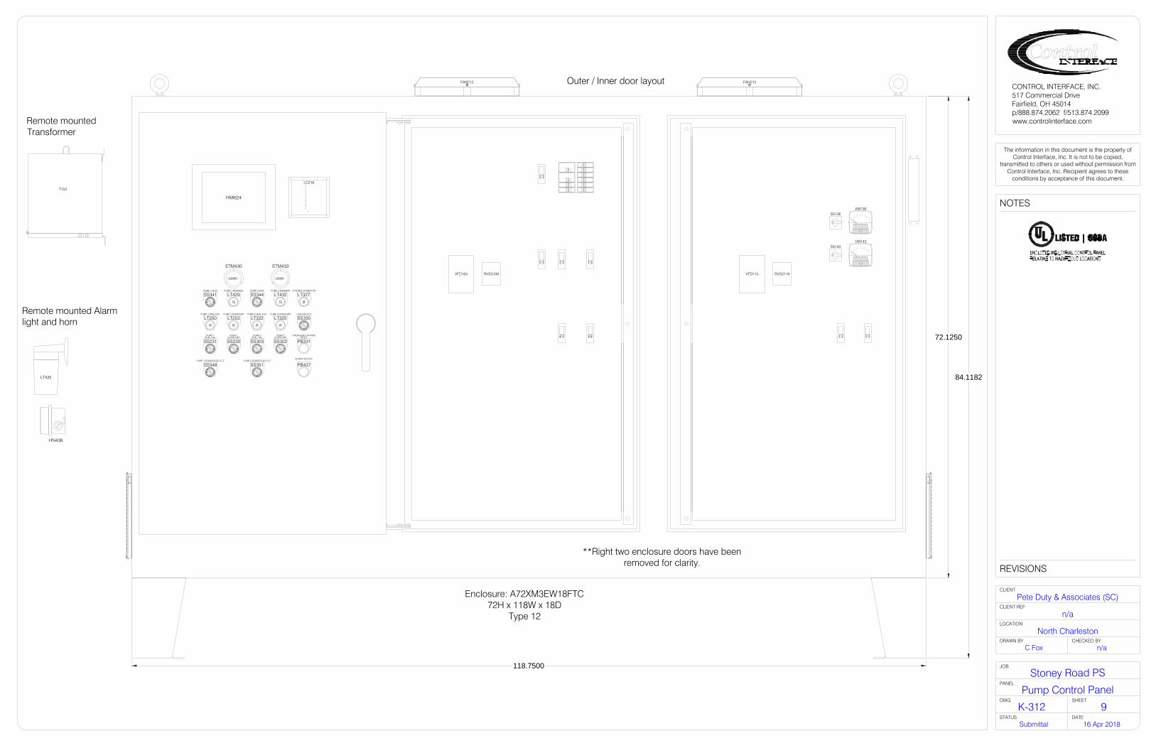
HMI624
LC216
LT435
T153
SS136AM136
SS143VM143
123456
ETM430
123456
ETM433
B
LT327CONTROL POWER ON
SS335LEAD SELECT
G
LT429PUMP 1 RUNNING
G
LT432PUMP 2 RUNNING
SS341PUMP 1 HOA
SS348PUMP 1 STARTER SELECT
SS344PUMP 2 HOA
SS351PUMP 2 STARTER SELECT
R
LT250PUMP 1 SEAL FAIL
R
LT253PUMP 1 OVERTEMP
R
LT322PUMP 2 SEAL FAIL
R
LT325PUMP 2 OVERTEMP
SS231PUMP 1
SEAL FAIL
SS230PUMP 1
OVERTEMP
SS303PUMP 2
SEAL FAIL
SS302PUMP 2
OVERTEMP
PB331RESET
EMERGENCY BYPASS
PB437ALARM SILENCE
HN436
Remote mountedTransformer
Remote mounted Alarmlight and horn
250A250A
Enclosure: A72XM3EW18FTC72H x 118W x 18D
Type 12
Outer / Inner door layout
72.1250
84.1182
118.7500
**Right two enclosure doors have beenremoved for clarity.
FAN212 FAN213
VFD105 VFD115RVSS109 RVSS119
NOTES
REVISIONS
The information in this document is the property ofControl Interface, Inc. It is not to be copied,
transmitted to others or used without permission fromControl Interface, Inc. Recipient agrees to these
conditions by acceptance of this document.
CLIENT
LOCATION
DRAWN BY CHECKED BY
CLIENT REF
PANEL
JOB
STATUS DATE
CONTROL INTERFACE, INC.517 Commercial DriveFairfield, OH 45014p/888.874.2062 f/513.874.2099www.controlinterface.com
DWG SHEET
North Charleston
K-312
16 Apr 2018Submittal
Pump Control Panel
Stoney Road PS
n/a
n/aC Fox
Pete Duty & Associates (SC)
9
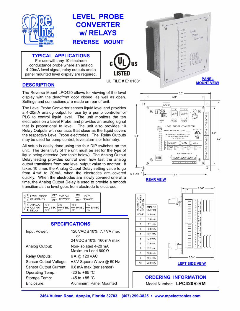
2464 Vulcan Road, Apopka, Florida 32703 (407) 299-3825 www.mpelectronics.com
TYPICAL APPLICATIONS For use with any 10 electrode
conductance probe where an analog 4-20mA level signal, relay outputs and a panel mounted level display are required.
DESCRIPTION
LEVEL PROBE CONVERTER w/ RELAYS
REVERSE MOUNT
ORDERING INFORMATION
Model Number: LPC420R-RM
SPECIFICATIONS
Input Power:
Analog Output:
Relay Outputs:
Sensor Output Voltage:
Sensor Output Current:
Operating Temp:
Storage Temp:
Enclosure:
120 VAC ± 10% 7.7 VA max or 24 VDC ± 10% 160 mA max
Non-Isolated 4-20 mA Maximum Load 600 Ω
6 A @ 120 VAC
± 8 V Square Wave @ 60 Hz
0.8 mA max (per sensor)
- 20 to + 65 °C
- 45 to + 85 °C
Aluminum, Panel Mounted
The Reverse Mount LPC420 allows for viewing of the level display with the deadfront door closed, as well as open. Settings and connections are made on rear of unit.
The Level Probe Converter senses liquid level and provides a 4-20mA analog output for use by a pump controller or PLC to control liquid level. The unit monitors the ten electrodes on a Level Probe, and provides an analog signal that is proportional to level. The unit also provides 10 Relay Outputs with contacts that close as the liquid covers the respective Level Probe electrodes. The Relay Outputs may be used for pump control, level alarms or telemetry.
All setup is easily done using the four DIP switches on the unit. The Sensitivity of the unit must be set for the type of liquid being detected (see table below). The Analog Output Delay setting provides control over how fast the analog output transitions from one level output value to another. It takes 10 times the Analog Output Delay setting value to go from 4 mA to 20 mA, when the electrodes are covered quickly. When the electrodes are slowly covered one at a time, the Analog Output Delay is used to provide a smooth transition as the level goes from electrode to electrode.
UL FILE # E101681
LEFT SIDE VEIW
REAR VEIW
PANEL MOUNT VEIW

CONNECTION DIAGRAM
2464 Vulcan Road, Apopka, Florida 32703 (407) 299-3825 www.mpelectronics.com
LEVEL PROBE CONVERTER w/ RELAYS

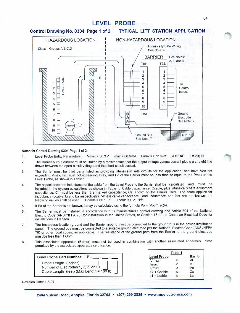

42 Level
Waterpilot FMX21Hydrostatic cable-mounted level sensor for clean water, wastewater and saltwater applications.
•Highoverloadresistance•Climate-proofsensor:pottedelectronics
•Robustceramiccellforlong-termstability
•Integratedtemperaturemeasurement(Pt100optional)
•Accessoriesforcompletemeasuringpointsolution
WaterpilotFMX21isarobust2-wire hydrostatic level sensor that comes in three versions to suit a wide range of applications which include the measurement of groundwater, wastewater and saltwater. It is also available with an integrated temperature transmitter as an additional measurement point.Waterpilotoffersavarietyof measuring ranges, configurable using HART protocol, and its potted electronics and double breather tube filters make it highly resistant to environmental conditions for reliable results, time after time.
Withmarineanddrinkingwaterapprovals,Waterpilotisavailablewith three diameter versions:•42mmheavydutyversionforusein
wastewater and sewage treatment plants
•29mmanti-corrosionversionforuse in saltwater applications
•22mmforuseinrivers,reservoirs,wet wells and boreholes, for e.g. groundwater level measurement
Technical data
Measuring range : 0...0.1 bar to 0...20 barReference accuracy : Standard accuracy ±0.2% (platinum ±0.1% optional)Long-term stability : ≤0.1% of upper range limit / year; ≤0.25% of upper range limit / 5 yearsTemperature range : -10...+70°COutput(s) : 4…20mA HART (Pt100 optional)Power supply : 10.5...30V DCProtection : Sensor IP68, terminal box IP66/67Sensor housing : Stainless steel (PPS coating for seawater optional)
SaltwaterClean water Wastewater
Serv
ices
&So
lutio
nsRe
cord
ers &
Syst
em C
ompo
nent
sA
naly
tics
Tem
pera
ture
Flow
Pres
sure
Leve
l
Serv
ices
&So
lutio
nsRe
cord
ers &
Syst
em C
ompo
nent
sA
naly
tics
Tem
pera
ture
Flow
Pres
sure
Leve
l

43
• Formoreinformation,specificapplicationadviceortoorder,pleasecontactuson0161 286 5000 or email: [email protected]• Todownloadtechnicaldocumentation,pleasevisitourwebsite:www.uk.endress.com• Forproductselectionhelp,tryouronlineApplicationtool:www.uk.endress.com/applicator
WaterpilotFMX21
Dimensions (mm)
225
240
ø22 ± 0.1
224 20
9
ø41.5
ø8
235
245
max. ø29
~
ø8
ø42
Wat
erpi
lotFM
X167
Seria
l-No.
:XXX
XXXX
XXXX
Mes
sber
eich
/ran
ge:0
...30
0ft
H20
INT.
SAFE
,CL
.I,DI
V .1,
GP.
ABC
DN
ON
INCE
NDI
VECL
.I,DI
V .2,
GP.
ABC
DA
Exia
IICT6
, Ta=
70°C
Entit
yper
dwg.
9605
03-1
009-
ø8
48m
ax. 5
2
22
17552
mm (in)
(1.8
9)
(6.89)(2.05)
(0.8
7)48m
ax. 5
2
22
17552
mm (in)
(1.8
9)
(6.89)(2.05)
(0.8
7)
Suspension clamp: stainless steel and fibreglass reinforced polyamide
FMX21 versions1 = 22mm outer diameter, stainless
steel2 = 42mm outer diameter, flush-
mounted, stainless steel3 = 29mm, stainless steel, PPS/
polyolefin for saltwater applications4 = Pressure compensation tube5 = Extension cable6 = Protection cap
Serv
ices
&So
lutio
nsRe
cord
ers &
Syst
em C
ompo
nent
sA
naly
tics
Tem
pera
ture
Flow
Pres
sure
Leve
l
Serv
ices
&So
lutio
nsRe
cord
ers &
Syst
em C
ompo
nent
sA
naly
tics
Tem
pera
ture
Flow
Pres
sure
Leve
l