Embed Size (px)
Citation preview

North Atlantic
'" /
TRAWL NETS
UNITED STATES DEPARTMENT OF THE INTERIOR
FISH AND WILDLIFE SERVICE
BUREAU OF COMMERCIAL FISHERIES
Fishery Leaflet 600

UNITED STATES DEPARTMENT OF THE I NTERIOR Stewart L. Udall, Secretary
Charles F . Luce, Under . ecretary
Stanley A. Cain, Assistant Secretary for Fish and Wildlife and Parks
FISH AND WILDLIFE SERVICE, Clarence F . Pautzke, Commissioner
BUREAU OF COMMERCIAL FISHERIES, Harold E. Crowther, '&cting Director
North Atlantic Trawl Nets
By
ROBERT A. B RUCE
Fishery Leaflet 600
W as h ington, D.C.
August 1967

CONTENTS
Introduction.
Explanation of twine cutting terminology.
Granton trawl ..
umber 41 trawl
Skagen or Type " S" wing trawl
Atlantic We stern trawl - model III.
Wing s and wedges
Lacing of t he net.
Headrope and hanging lines.
Ribline s ..
Bellylines
Wing end rope s .
Floats ....
Roller gear
Legs and ground cable
Quarter ropes and beckets
Splitting strap and codend rope
Laceage on the side panels
Polish factory ship's tr awl.
umber 36 trawl
"60 - 80" trawl
Whiting trawl.
Flounder trawl.
60-Foot shrimp trawl
Acknowledgments.
References .....
111
Page
3
5
6
8
11
11
12
12
12
12
12
12
13
13
13
13
13
15
17
18
20
21
23
23

North Atlantic Trawl Nets
By
ROBERT A. BRUCE, Fishery Methods and Equipment Specialist
Bureau of Commercial Fisheries Exploratory Fishing and Gear Research Base
Gloucester, Mass. 01930
ABSTRACT
This leaflet is designed to answer requests for information about otter trawls currently used in the No rth Atlantic fisheries. Its major emphasis is on trawls used on ew England trawlers, but it also includes some of the trawls used by other countries fishing the fishing grounds of the northwest Atlantic .
Data such as overall size, twines, mesh sizes, rope and wire size, roller. and chain gear, flotation, rigging, and certain construction details accompany the draw ing s and texts for each net described. The designs cover trawls for vessels from 55 feet with 220 -hp. (horsepower) engines to 250 feet with 2,400-hp. engines.
INTRODUCTION
Recent developments in the design of trawl nets in countries with relatively la rge fishing fleets suggest that the f ishing efficiency of the otter trawl can be imp roved. Papers descr ibing various tests on new and traditional trawl nets have established certain facts about these nets and have elaborated on the problem s with both relatively standard de signs and with altered or new nets. Continuing exper iments with new ana lmprovtd instruments have provided more information on nets and suggest the possibility of further improvement in trawl design. Sometimes test results are contradictory or inconclusive, but total knowledge on net charac te ristic s is inc reas ing, and the belief persists that trawls c an be made more efficient if the net and its gear are modified.
One of the results of these varied activities has been the experimental trial and actual use of trawls of a design other than the "typical" otter trawl. These different nets are called "new" by many because they differ in some respects from what is commonly being used; however, many of these so- called innovations are not new. For example, when examining two of the more frequently discussed types of nets--the wing trawl and the box or 4-seam trawl- - we find that wing trawls have been suc cess fully used in Scandinavian fisheries for over 50 years and that a box t rawl was patented in England over 40 years ago.
Increased trawl and gear research, comparative fishing tests between the "st andard"
and "new" nets, and economic expediency have led an increasing number of foreign fishing vessel operators to try different trawl nets. New England trawl fishermen have recently turned to increased experimentation with standard trawls, "new" trawls, and new materials. E fforts to change New England otter tr a wl s include altering the wings, changing the headrope and footrope length ratios, expe rimenting with reducing lower wing damage, and changing the lengths of legs and ground cables. Because of these diverse changes it is difficult to describe a typical "name" net, and to do so is to invite the reader to compare the net with which he is familiar to the "name" net illustrated here-the differences may be considerable.
This leaflet illustrates som e of the typical nets that New England, European, and Canadian fisherI!1en use in groundfishing. Rigging details on the 2-seam trawls are restricted to the wing and mouth areas for most of the nets illustrated because of the similarity in rigging such parts as the bellies and cod ends of all 2-seam trawl nets. Greater attention to the differences in rigging is given the 4-seam or box trawl and the Polish factory stern trawl.
EXPLANATION OF TWINE CUTTING TERMINOLOGY
This brief description of cutting tapers uses the terminology most common in the United States and Europe. This cutting method is • based on the parts of a mesh or meshes

(p)
(m)
(PI
(m)
St retc hed Length
Poi nt (P)
Sar (b)
Mes h (m)
Sar ( b)
I Fi,ure IA - P art . of a me .h
(1m2
xx ~ '& ~ ~ ~ 0 X
'<
~ ~ b) ~ ~ ~ (2mlb)
~ ~ ~ X ~
X
Fiaure IB - Webbing cut along me.he. and point • .
Figure ie - Webbing c ut aio n g bars .
Fi gure I D - Webbin, cut in c ommon t~pe r • .
Figure IE - Webbing c ut along poi nt. and bar.
(Imlb) (Im2b)
Figure IF - Webbing cut uoing combination of cut • .
(2m lb) (3ml b)
Figure I A.-- Nomenclature of a mesh. IB.--Webbing cut along meshes (m) and points (P). lC.--Webbing cut down along bars (b) both s ides . ID, IE, and IF .--Illustrations of typical tapers.
that remain along the t apere d e d ge after bars are used in the taper, the mesh is given t he unwanted webbing is cut away. first. On North Atlantic trawl nets, points
Figure IA shows a mesh w ith i ts parts (p) are found almost exclusively in the wedge n a med and those parts that may remain sections if these sect ions are used. along the tapered edge of a net section. Figure IB shows a piece of webbing having
Meshe s (m) and bars (b) make up most both vertical sides cut along meshes--this of the parts in most tap e r s of trawl cut is known as a "straight cut down." The net sections. Either meshes or bars, or a illustration also shows both horizontal edges variety of c ombinations of meshes and bars, cut along points - -this cut is known a s a will be used. In this leaflet, if meshes and " straight cut across ." The resultant webbing
2

section, w h ic h is c ut a long m es hes down and points a c ros s, is rectangu la r ; t he re i s no tape r in thi s s ect i on. It i s a lways ass ume d that when n ett ing i s cut , t he we bbing h ang s in a stretc h ed me s h c ondition.
F igure IC s how s a piece o f webb ing cut along bars (b ) on eit her sid e and points (p) across t h e t op. Thi s c ut , along bars only, re sults in a d i a gonal c ut t hrough the s ec t ion of web b in g . T he common dog-ear or fl y - me s h e d ges o f m any wing sect i ons are m a d e f rom this c ut along bars .
F igure s ID, I E , and I F show v arious c ombinations of c utt ing s t h at result in t ypical t apers . N ote t hat figur e I F s how s combina t ion s of more than one seque n ce o f meshes and bars. T hi s combination re moves the un wanted w e bbing and p rovid e s t he desired t aper when one sequence of meshes and bars i s unable to give t he intended taper. Stand a rd n e t making p r ac t ice allo ws a differe nc e of one mesh fro m t he ne t 's plan specif ic a t ions.
T he t apers included in thi s leaflet came, whe never po ss ible, from the s ources supplyin g the diagrams and descriptions of the e nclo sed nets. When this taper information w as n ot s upplied, I used a standard method of de t ermining tapers.
GRANTON T RAWL
T he Granton trawl (fig. 2) is the standard net t hat has been used for the past quarter cen t ury aboard large deep-sea trawlers in
England . This net and the Abe r deen t rawl a r e t he most c o mmon tr awl nets now u s e d by Bri t i s h t rawlers a n d a r e s im ilar to mos t of the d eep - sea, bottom-fis hing , 2 - seam nets used in c ontinent al Europe.
The d e s igners of the Gran ton t rawl have a l ong t rad it ion of bottom trawl expe rience dating back to the beam trawl. These d es igners made c hang es to t h e o l der trawl s so tha t t he ne w nets c ould m eet t he r equi rem ents of l a r ge r ve ss e ls , which had mo r e po we r , f i s he d on new and rough fishing a r eas , and had n ew e quipment s u ch as o t ter doo r s, danlenos, and t he Vigne r on -Dahl (V - D) door hookup gear. To obt ain good fishing characteri s tic s the uppe r and lowe r wings were va r ied in widt h and length, the length and mesh s izes o f the bellies we r e changed, and the sect i on tapers and hanging ratios we r e a ltered. All these changes led to an effective groundfish ne t . An accepted feat ure of this net is that the l ower wing, measured along the selvedge, is 10 percent longer than the combined upper wing and square . This difference allows the webbing to lift and pro vide greater headrope height. T wo sizes of the Granton trawl popular in the British distant-water fisheries emerged from these efforts--one w ith a 116-foot footrope (fig. 2) and a l a r ger trawl with a 136-foot footrope.
The need for easy assembly of the net ashore and the need for replac ement sections to expedite repairing the net at sea enc ourage d m anufacturers to standardize the nets. T he current trend away from h and-
Table l.- - Cons t ruction details for the Granton trawl
Part
H ead r ope ......
Fi shing line .............. .
F oot r ope .. . . . ............ . . Wing end rope ... ...... . . . Hanging line s ............ . Floa ts .... . .... ............ . R o llSor gear . . ... ......... .
F ootrope for s eab e d fishing (flatfi s h ) . . ....
Belly line le g s . . ... ... . . . .
Selvedge l in e s ... . . .. . . .. .
Specific ations
One piece of 4" cir. (circ umference) manila or synthetic rope, 78 ' (feet) long, marked 29' - 6" (29 feet, 6 inches) from each end . Allo w for eye on each end.
Seven lengths of 7 / 8" dia. (diameter) comb. (combination) wire rope: 14' - 6"; 14' - 6"; 20'; 20'; 20'; 14' - 6"; 14' - 6". Total length 118', without allowing for connecting links. A 120' footrope c an be used.
1" dia . 6 x 19 wire. Same measurements as fishing line . Two lengt hs 7 / 8' dia. comb. wire rope, 4' long. 1/ 2" dia . rope. Top and lower wings. Fifty 8" dia. aluminum floats. 20 on bosom, 15 on each wing. 20' foot rope units for bosom and quarters.
Bosom: Five 24" dia. or seven 21" dia. iron bobbins, spacers as needed. Quart ers: Five 21" dia. or seven 18" dia. iron bobbins, spacers as needed. Wing s : 4" to 6" dia. rubber disks along 14' - 6" lengths of footrope. Roller chains p l aced at 4 ' int ervals.
Seven l e n gt hs of I " to 1-1 / 4" dia. wire rope. The s ame mea s urements a s t he fishing line . Round all wire s with 2 -1 /2" ci r. mani l a rope.
One piece 5 / 8" dia. 6 x 19 wire, 13' - 6" long, eye each end. Runs f rom fo otrope qua r ter s hackle along a bar to s elvedge.
3" ci r . r ope , sei z e d a long selvedge from bellyline legs to end of cod end.
3

Stretc hed Mellh St retc hed
HEA DROP E Twine 17 FOOT ROPE Lenst h
Ll Taper
I Taper
i Win, 29'-6 11 Wing 49'
Wi n, 29'-6" All b Wing 49'
Bo.om 19'-0" Bosom ZO'
Total 78'-0" Total l"TF Z9-1/ Z' All b
1 5- 1/ Z" 61 '
i TciOT3 Manila Im4b
1 Z7-1 / Z' j 1 zoo
t zoo t • 8-1/4'
5-1 / Z" t ZZ' ~ Ma nila Manila 9-I/Z'
1 ! + .. 1 t t 1 5 -1 /4" Z6-1/4' 5-1/4" 9OT3 zz' ~
1 ManJ 1. M.nila
! • ! 1 t t
5-1/ 8" 50 Z 1- 1/ z' All m ~ Z I - 1/ Z'
Mani la
! ! ! 1 1 Im6b i Z(lm5b)
30' 68 All m 5- 1/ 4 " 5fiT4 30'
Double Mani l.i.. All m 50
1 1 70
Machine Woven
Q)wedge Detaih:
><>-><><')..~ ><><>-
X X v
l@
Bar
/ Point
XAi >
50
Hand Woven
Taper: l p lb
In joi ning we dge to wi ng . notch ca n be cut in wing to ac commodate wedge as sh own.
Figure 2.-- Granton trawl.
made sections and t owa rd the use of machinemade webbing stimulated developm ent of a more simplifi e d design w ith a two-part belly and straight cod end (fig. Z, left illustration).
A wedge section, identical with or similar to that used on the t op wings, is often included on the lower wing s. W ith machinemade webbing, this wedg e is a s imple ad dition to the net. Th e wedge is used because fishermen believe that it strengthens the "strain" area s and he 1 p s maintain the proper "set" of t he net while it is being towed.
4
The ever-widening search for groundfish by British vessels requires that the Granton trawl be fished over rougher seabeds than in the past. To reduce gear damage and loss to an acceptable level, both t he net and its rigging have been changed. An example of these changes (the Polish factory ship's trawl) i s illustrated in figure 7.
Although p r im a r i 1 Y roller-rigged for groundfishing, the Granton trawl is occa sionally used on s mooth b ottom when fis he r men wi s h to tow the net clo s e to the seabed. The roller gear is removed and a heavy wi re - rope foot rope i s hung to the net.

Construction details for the Granton trawl given here apply to trawls made of both machine-woven and handwoven netting. Some of the terms used are those common to t he English fishermen. The difference s that would exist between the machine-woven and handwoven nets are primarily in the bellylines, bellyline legs, splitting straps, haul-up ropes, and strongbacks (if used). The sizes and measurements for these units are not included except for the bellyline leg-- i t i s t he only ite m that may be unfamiliar to AInerican commercial groundfishermen. Not ice t he longer belly and the tapered cod end in t he handwoven net (fig . 2). These are not meant to coincide with the machine-woven net but specifically to provide an example of change s allowable in the Granton trawl.
NUMBER 41 TRAWL
The basic trawl net used by the large draggers and "beam trawlers" from New England ports is the Number 41 trawl (fig . 3). This European-designed trawl replaced t he Icelandic t rawl in New England about 20 yea rs ago because of the difficult y of acquiring Icelandic nets and spare parts. Sections for t he Number 41 trawl used in t hi s country
Mesh Twine
have gene ra lly been Imported from E rop . It produces satisfactory YIelds compar d 0
its larger p r edecessor. Fe w changes have been made to he bas1c
Number 41 trawl m recent years. The bel.y has been simpllhed by reduc mg th numbe r of mesh sizes from t hree to one (to accommodate mesh regulatlOnsl. and th len h of the wings have changed slightly. Th h adrope and foot rope lengths have remamed a t 79 feet and 100 feet, respectIvely.
Number 41 nets, until recently, have been made of manIla hemp t-wme. Use of new fibers--nylon, polypropylen, and polyethylene--m net twines has progressed to he point where most of the I':umber 41 trawl in use today are composed of synthetic. s. Notable exceptlOns to this trend are tre cont inued use of manila bottom bellies and lower wings aboard vessels fishing on hard bot om where nets are subject to repeated dama!le. The Number 41 i1lustrated 15 a tWlstednylon net except for the cod end, which 15 o f No . 102 braided - nylon. An extensIOn (If used) could be made of 1':0 . 200 polypropylene . Fig. 3 shows a umbe r 41 trawl win. a bel:)' 77 meshes deep; 90 - mesh beilles are ava.lable for large trawlers.
The major difference be t ween the Granton tr awl and the I':umber 41 trawl used by rrany
Str~tch~d F'OOTROPE
Stretched Length HEADROPE Taper Taper BOlom 13'
1 3 5- 1/2'
1 t
12 - 1/2'
~
1 32'
1 t
18-3 / 4'
l
Bosom 15' Win g 3 2 ' Wing 32' Total 79'
Imlb
8' 2(2m Ib)
5" , S4
Polypropylene
Im 7b Im bb
t
33
Im4b 31.
50 All m 4 - 1/ l ' '1 02 N ylon
35 ! Figure 3.--1 'umber 41 trawl.
5
WIng 43-1/2' WIng 43-lll'
Total 100'
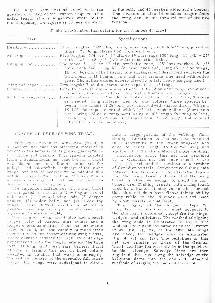
of the larger New England trawlers is the great e r overhang of the Granton's square. This extra length a llow s a great e r width of the mouth opening; t he square is 30 meshes wider
at the belly and 40 meshe s wider at the bosom . The Granton is also Z4 meshes longer from the wing end to t he forward end of the extension.
Table Z. - - Construction details for t he Number 41 trawl
Part Spe cif icat ions
Headrope ................. . Three lengths, 7 / 8" dia. comb. wi r e rope, each Z6 '-Z " long joined by links = 79' long. Marked 3Z ' fro m each end.
Footrope ............. . .... . Five lengths, 3/ 4" or 7 /8 " dia . 6 x 19 wire rope 100' long: 18 l / Z' + Z5 ' + 13' + Z5' + 18 l / Z'. (Allow for connect ing links. )
Hanging line ......•.... ... One piece 3 1/ 4" or 4" ci r. synt hetic rope, 105' long marked 45 l / Z' from each end. Hung 45 l / Z' from each end. Hung 45 l / Z' on wings , 14' on bosom. (T he hanging line arrangement described replaces the traditional light hanging line and wire fishing line used wit h roller gear. The roller chains secure directly to this heavy hanging line .)
Wing end ropes ........ .. Two lengths 7/ 8" dia. comb . wire rope, 6' & 11' long . Floats .................... .. Fifty to sixty 8" dia. aluminum floats, 10 to lZ on each wing, r emainder
on bosom . (Some nets have 1 to Z extra floats on each wing end . ) Rolle r arrangement .... Bosom rollers - 6 or 7 wooden or rubber rollers 16" to 18" dia. Space rs
as needed. Wing rollers - Ten 16" dia. rollers, three spacers between. Remainder of Z5 ' long wi r e covered with rubber discs. Wing s -18 l / Z' footropes covered with 3 l / Z" dia. rubber discs. (Some nets alter wing roller arrangement using a 30' length for wing rolle rs. Remaining wing footrope is changed to a 13 l / Z' length and covered with 3 l / Z" dia. rubber disks.)
SKAGEN OR TYPE "S" WING TRAWL
The Skagen or type "S" wing trawl (fig.4) is a Z- seam net that has a ttracted interest in recent years because of its growing acceptance in Europe and Canada. This trawl is adapted from a Scandinavian net used both as a trawl with doors and as a Danish seine net for pelagic and bottomfish. Redesign of the lower wings and use of heavier twine adapted this net for rough bottom fish ing. The result was a higher opening net t hat had the qualities de sired by many fisherm e n.
The important differences of the wing trawl as compared to the large New England trawl nets are: (1) dovetail wing ends, (Z) deeper square, (3) wider belly, and (4) wider top wing s. These factors result in a net with a greater overhang, a larger mouth area, and a greater headrope height.
The original wing trawl also had a much longer belly of various size t wines and a longer extension section; these measurements we re reduced, and the varie t y of mesh s izes elim inated on the bottom -fishing wing trawls. These changes reduced the high rate of damage experienced with the longer net s and t he time lost patching multimesh -size bellies. First e fforts at fishing this net on hard bottom resulted in cat che s that we re encouraging. To reduce damage in the normally full lower wings, the wings were rede s igned to elimi-
6
nate a large portion of t he webbing . C ontinuing alterations to this net have resulted in a shortening of the lower wing - - it w as once of equal length to the top wing and square -- and the elimination o f m ore webbing .
Information about this net was provided by a Canadian net and gear supplier . who sells t his net and its sections to a number of Canadian vessel s. Comparative fishing data between the Numbe r 41 and Granton trilwls and the wing trawl indicate that the wing trawl is effective enough to merit it s con tinued use. Fishing results wit h a wing trawl used by a Boston fishing vessel also suggest that this net does have f i s h - catc hing ability comparable to the Numbe r 41 trawl used by mo st vessel s in that fleet.
T he rigging of the Skagen or type "s" wing trawl is similar in most respects to the standard Z-seam net except for the wing s, wedge s , and bellyline s. The method of rigging the wing end s i s illustrated in fig. 4. The wedge s are rigged the same as in the Granton trawl (fig. Z), or, if the alternate wing s a re used, the wedge s may be eliminated (fi g . 4, (1) and (Z)). The bellylines on this net are similar to those of the Granton traw l, for they too run only from the quarters to the selvedge. Selvedge lines are then required that run along the selvedge at the bellyline down into the cod end. Standard methods of rigging the cod end are used.

Stretched L e nsth
t zO'
1 t
15-I/Z
! 1 2 5 '
1 1
3Z'
1 t
13'
! t IS'
1
Im3b I mZb
Im Zb
H e ... drope Me l h Wing 3Z' Twine T aper Wing 3Z' BOlom 16' Tota l SO'
5-I/ Z" ~
Polypropyl ene All b
i ImZb 190
Imlb
t 5" ~
Polypropylene
~ t
4- 1/ Z·' ~
50 Polypropy.ene Double
t 4S All m 4-I/Z "
~ Nylon
50 ~
Alternate Top Wing
Alternate Bottom Wing
These alternate wings will fit the above net maintaining the same head rope and {ootrope measureme nts .
Footrope Win, 49' Win, 49 ' BO IO<11 IS' Total 116'
5t retched L en th
Note: Leg and Bridle Arr ... nge m ent
5 ugge sted leg length 15 - 20 (uhom I Top leg I foot longer th ... n lower leg
IS Fm s . + I ft .
15 Fms
• 8' • t
14- 1/2'
~ t 18'
l • 7 - 1/2' •
Figure 4.--5kagen or type "5" wing trawl.
7

Tabl e 3. --Construction detail s for the Skagen or Type "s" wing trawl
Part Spe cifications
Headrope .. .... .......... . . Three lengths 7 / 8" d ia . comb. wire rope, 80' long: 32'; 16 '; "32'. F ootrope .. ................ . Seven l engths 7 / 8" dia. wire rope, 116' long: 14 ' ; 20'; 15'; 18'; 15'; 20' ;
14' . F Ishmg lines . .........•.. Five lengths 3 / 4 " dia. c omb. wire rope, 95' 6" long : 21' 6"; 16' 6"; 19 '
6"; 16' 6"; 21' 6" . WIng end bnes .......... . Two lengths 3 / 4" dia. comb. wire rope, 40' long, ma~ked 20' from eyes .
Two l engths 5 / 8" dia. comb . wi re rope, 8' long, wIt h e ye on each end. 1-1 / 2" ci r. polypropylene rope. Hanging lme ........ . •....
Bellylines ................ . Selvedge lines ........ . .. . Quarte r rope s ........... .
Two lengt h s 3" cir . polyp ropylene rope, each 13 ' long wit h eyes. Two lengths 3 " cir. polyp ropylene r ope; length equal to selvedge. Two lengths 3" cir. polyp ropylene rope, 90' long .
Haul - up line ............. . Roller gea r .... . .. ....... .
One length 2-3 / 4 " ci r. polyp ropylene rope, 110' long." " R o ller gear to suit on footrope wires given. Rubber dISks on wmgs stop
at end of lower wing . Bare or rounded wire thereafter. Floats .............. .... .. .. Suggested no. 36 , 8" dia. aluminum fl oats: 18 on bosom, 9 each on wing s .
ATLANTIC WESTERN TRAWL -MODEL III
The Atlantic We stern trawl - model III (fig. 5) is one of a series of 4 -s eam or box trawls desIgne d by W. W. Johnson of the Industrial Development Service, Departm ent o f Fisherie s of Can ada. Re sults of fishing exper iments by the Canadians suggest tha t th is ne t is an effectIve groundfish net, espec ially for use at ni~ht for species that t hen rise off the bottom. A headrope height of 20 feet claimed for the net was substant iated by tests made aboard the Bureau o f Com mercial Fisheries H.. V. Delaware.
Compa r ed to a 2 - seam trawl , thi s 4 -seam trawl embodies four major depa rtures that are app arent at first glan ce: (1) top and lower wings are one pie c e o f w ebbing; (2) the use of wedges and how they are attached to the wing s are different; (3) four selvedge s, hence four selvedge lines, or r ibline s, are used; and (4) the taper along the wings is not cut as do g - ears .
Any di ff ic ulty in making this net would probab ly arise from its departure from usual 2-seam net construction and not from its compleXIty .
Conce rn about extensive net damage and lost tIme a t sea due to repairs to this type of net have not been supported by the actual e"<penenc e of fishermen aboard Canadian or enited States ve ssels. Damage when working rou~h bottom has, in most instances, been Iln)l ted t o the lowe r belly and t hose wing dreas whe re the re are no tapers. The belly IS repaIred in the same manner as the larger be:;y of the 2-seam trawl. The modelIIItested aboard the Delawa r e held i ts spec ified measurements unde r normal hard-bottom fishing,
8
and this lack of chang e supports the belief that the balance of the n et is st able.
The application of 4 -seam trawl s to g roundfishing operations in the No rthwest Atlantic is r elatively recent, and c h anges are being made to t hese nets t o facilitate fishing on rough bottom s. The model III described inco r porates the lat e st change s c urrently available and is c o n s ide r ed t he best Atlantic Weste rn net for fishing hard bottom.
Figure 5 shows t he net laid out in four panel s. Panels 1 and 3 sho w the side and wing panels. Panel Z s h o ws the top w ebbing . Panel 4 shows the bottom webbing. T he figures to the left of Panel 1 a re the webbing' s stretched mesh measu r ements, which are familiar to mos t net builders. The mesh c ount for all sections of t he n et, e xcept t h e wedge s and square, are given in Panel 1. T he w edge details a r e given in fig. 6B, and the width of the squa r e i s given in P anel 2. Along the left edge of P anel 2 are the ribline measurements from the we d ge down to t he c od end. These co rrespond to the selvedge or gore lines. On t he r ight side of Panel 2 are the lett e rs A t h rough E which are placed alongside points on the r i bline where adjustments can be made to realign the net when damaged and chec k m easurem e nts when buildi n g. Letter A designates the forward end of the wedge and square ribline. Panel 3 names t he various se c t ions and gives the tapers of all sections except t he square which is found in Panel Z. Shown above Pane l 3 is the length of t he wing end rope and its hanging measurements . Panel 4 shows the bottom section, illustrates the bellylines and the breakdown of the footrope. The bellylines on this net function as strongbacks and not, a s in a 2-seam trawl, to transfer the strain

Stretched
T 20-1/2'
1 t
10-1/ 2'
~
1 T + .... _"'6 .. 0...,
1 34'
1 t
IS-1/2'
J f
IS- 1/2'
1 f
IS-1/2'
1
91)
30
50
20
50
Panel I
HEADROPE
Wing Wing BOllom Total
29'-5" 29'-5" 17'-6" 76'-4"
............. c
17'-9 "
o
Panel 2
CD Cutting of wedge on Figure No . 6 B .
4m lb
17'
4mlb
" o
'" " ., >i til All rn
Panel 3
All m
FOOT ROPE
Wing 49'-6" Wing 49'-6" Boaom 17' Total 116'
IS' -6 "
21 '-6"
Panel 4
Mesh Twine
5" 17 5 Bra! ded Polyethylene
4--1/2" 175 Braided
Polyethylene
t 4-1/2 " -zoo--
Poly propylene • t 4 - 1/2"
102 Nylon
l
Figure 5.--Atlantic Western trawl - model III.
fr om the quarters to the selvedge. To the right of Panel 4 are the mesh sizes (stretched mesh) for each section along with twine fiber and size. A broken line 25 meshes up from the lower edges of the side panels is drawn on P anels 1 and 3. Major areas of damage are encountered below this line and will be mentioned late r. The construction details are
9
fairly standard as in other nets; thi s se c tion does, howeve r, give additional information for the assembly and rigging of thi s net.
Figures 6A, 6B, 6e, 6D, and 6E illustrate the shape of the wedge and other details which are departures from usual 2-seam net construction.

o Wing - - Showing L oop . and Wedge L a ci ng
lace 4 knot . from Wlng and wedge .
Bunt
--Gathe r 4 knots along edge . having loops .
Squa re
® C on.t ru c ti on and RiggIng of Co d End :
10
10
o I~ Cod End Ri Two me s he pe r ring.
n/, 25 Me shes
18 M eshes ~,
SP"Ui/ Strap
3" Cir . Poly p ropy lene
- -9' - 6"
Cod
Lacing
-- -
©
M e s h Count and Taper o f We d ae :
We dg e gathe re d and la c e d to wI n pI e c e Ext ra me.he . on to p of wedge woven I nto
last mesh of flyln Wlng
lmlb
W e d ge
Constru c tIon of Straight Extenllon: Ga the r 3 knots from ea ch sIde and la c e
20
25 Meshe s
9'_ 4 " Rib li n e
E n d 20/ Exte n . i on
Ri b li ne - 4 kno t s 10
- -- - -- -- 2U 10
Rib li ne
No slac k in laci n g . Ga'ther 2 k not .. a n d se i ze rib li ne with hitch every m esh .
17' -9" l' Seizing.
Figures 6A, 68, 6C, 60 , and 6E.--Construc tion diagrams of the Atlantic Western trawl - model ill.
10

T able 4. - -Construc t i on de tail s for the Atlantic Western t rawl - model III
Part Specifications
Headrope ................. . Three l engths 7 / 8" dia . comb. wire rope 76'-4" long: 18'-11" + 38' - 6" + 18 '- 11" . 38' - 6" length marked 10 ' -6 " from ends .
Footrope .................. . Seven l engt h s 3 / 4" or 7/ 8" dia. 6 x 19 wire rope 116' long: 18' - 6" + 9 '-6"+ 21 '- 6" + 17' +21' - 6"+ 9'-6 " + 18' - 6" .
Wing end rop e .. . .. . ..... . Two l e ngt h s 3" cir. nylon rope, 17' long. Fishing line ..•........ . ... One lengt h 7 / 8" dia. comb. wire rope 18' long. Hanging line . . . . ... .. . . .. . Five len g t h s 2 - 3/ 4" cir. polypropylene rope: 9' - 9" + 22'-4" + 19'
+ 2 2'-4 " + 9 '- 9" . Two lengths 2-3 / 4" cir . polypropylene r ope for fly ing wing t aper - each 20' - 4". Eye at each end.
Rib lines : Wings and square s ... T w o 34'- 6" lengt hs of 2 - 1/ 4" ci r. polypropylene rope, eye one end.
Marked a t s uccessive intervals, 22' and 9 '- 6" from eye . Belly to c odend . .. . .. . Four 81 '- 8" lengths of 2-1 / 4" cir . polypropylene rope, no eyes. Mark d
at succe s sive intervals, 3'; 33'-7"; 18'; 17'-9"; 9' -4 " from one end. Floats ..........• .. . . ....... Rollers ............. . . .•. ...
Thi rty- six 8" dia. aluminum floats. R oller gea r and rubber disks to suit on footrope wires up t o flymg
w ing. L a r ge diame t er rollers (20 " ) recommended. Belly lines ...•... •• ....... Two lengt h s 1 - 1/ 2" cir . polypropylene rope 45' long.
The a c companying diag r am s (figs . 5 and 6) provide most of the neces s a r y information for buildin g t he Atlant ic We stern trawl - model III. There are five o r s ix models of this net, although t hey are b a s ically the same net of v a r iou s sizes . Diag r am s fo r a given model should be on hand if a t ype of Atlantic W estern trawl , o t her than model III , is to be built. The fo llowing informat ion is intended to suppleme nt t he accompanying diagrams r athe r than t o be complete instructions in themselve s.
Wings and Wedges
The wing s o f the Atlantic We stern trawl are made up of thr ee pieces of webbing-t he flyin g wing, the wing, and the bunt (fi g . 6 A )--and s e r ve a s t op and bottom wings. A wedg e , c ut a s shown in fig. 6B, i s attached to the wing piece as shown in fig. 6A by g athe r in g four knots from each and lacing i n the s ame manner as JOlnlng selvedges. The r e m aining meshes at the forward end o f t he wedge are secured to the meshes of t h e fl y in g wing.
L o ops or dog - ears are added to the top and lower edge s of the wings, the bunt, and the we d ge a ft e r four knots are gathered and laced a l ong t hese edges. (This gathering of knots creat es a strong area t hat is seldom torn o u t, allowing uncomplicated mending of damage d webbing in t hi s area.) On the flying win g a l oop of heavy or double twine is started wit h a hit ch around the first group of knots a t t he wing end . The next hitch, which for ms t h e l oop , is made on the second group of knots down from the first hitch so that there will b e one group of knots in t he middle of
1 1
the loop that does not have a hltch bent to 1t . The loop then is equal to 1 mesh 10 length (fig. 6A). This method of looping is cont inued along t he flying wing and wedge down to th square.
On t he lower edge of t he wmg and alon~ the bunt, loops are made 1n the same manner. For accuracy in weaving the sections togethe r, meshes at the bottom of the bunt and wedg shOuld be left free for securmg to belly and square and finished after these sectlOns are woven together.
LaCing of the Net
The sect ion s of th1S net are woven togethe r with double twine down to the cod end. Assembly of the net can be started by lacm~ the selvedges along the top and slde panels. The bunts and squ a re are laced mesh for mesh, gather ing four knots from eacr section. Contmuing along these seams, mesr. for mesh, the belly and tapered extenslOn panels are gathered four knots and lac d. The straight extension i s assembled by folding each plece of t wme lengthw1se 20 meshes from an edge along a row of knots and gathe ring and lacmg three knots from each slde of the folded co rners and three knots from each side of t he selvedges (f1g . 6C). j ot that the bunt - square lac 109 aligns wi h he wedge - wmg lacing . The bottom panel can be laced to t he s ide panels 10 the same manner except that the startmg pOint 1S the lower belly.
The cod-end p1eces are laced toge her as shown in fig. 6D and the cod end woven into the extension, thus completmg the webbtn assembly.

Headrope and Hanging Lines
The headrope should be attached first as it assists in bending on the top riblines. The headrope is made up as specified in Table 4. Allowance for connecting links is made, and the headrope is marked at the quarters as indicated. The headrope is attached to the webbing in the usual manner- -the connecting link being lined up with the flying wing double twine, and the quarter mark properly located where the square and wing meet.
A 2 3 4-inch circumference polypropylene hanging line is made up as per Table 4. The 20-foot 4-inch length is bent along the bars of the flying wing. The 9-foot 9-inch length is seized to the 20-foot 4-inch length and attached to the wing piece by the loops (dogears). The 22 -foot 4-inch length of 2 3/ 4-inc h polypropylene is seized to the 9-foot 9-inch length and secured to the bunt by the loops. T he 19-foot bosom length is seized to the 22 -foot 4-inch length and hung to the bosom meshes . Care should be taken with both head rope and hanging lines to make certain that the Lls tribution of the webbing along these ropes is even .
Riblines
\\'mg -square riblines.--These r ibline s are made up of lengths of 2 1/ 4-inc h circum fe rence polypropylene rope and are marked as describe d in Table 4. They are hung to the selvedge with seizings 1 foot apart, startmg with the eye at the top belly-square double t wine, so that the 22 -foot length is evenly spaced with the square selvedge and the 9-foot 6-inch length with the wedge selvedge. The 3 -foot remainder is passed through the eye on the head rope . drawn up t o align the 9-foot 6-inch mark with the headrope connecting link, and properly secured to the eye With a bend or hitch. The free end is seized back onto the ribline.
Belly-cod end riblines.--The top r ibline s, from the belly to the cod end, are two equal lengths of 2 1/ 4-inch ci rcumference polypropylene rope, without eyes, marked as sho ·..vn in fig. 5. The belly ribline is se cured to the eye in the wing-square ribline at the 3 -foot mark. The 33-foot 7 -inch length is seized to the belly every foot, the 18-foot length to the tapered extension, the 17 -foot 9 - inch length to the straight extension, and the 9- foot 4-inch length to the cod end (stretch the cod end when bending on the ribline).
The two bottom riblines are secured to the bottom selvedges in the same manner as their top equivalents with the following exceptions: (a) the 3-foot mark is secured to the eye of the bunt hanging line, and (b) a 3 -foot 9-inch length of ribline at the quarter is left free from the webbing t o allow slack in the laceage in this area.
12
A 9-foot 4-inch length of 3-inch circum fe rence polypropylene is seized every mesh along the side laceage of the cod end as shown in fig. 6E. As an alternative to this cod end arrangement, the 2 1/4 -inch polypropylene ribline s can be extended through the cod end .
Bellylines
The bellylines on this net differ from those of the usual 2 - seam trawl in that they cross from the quarters to the opposite selvedge . They consist of two pieces of 1 1/2 - inch circumference polypropylene rope about 45 feet long, which are secured to the eye o f the bosom hanging line 5 meshes inward from the selvedge and are laced along the bar to the ribline on the opposite side. The re they are secured to that ribline with 3 to 4 seizings for a length of 1 1/ 2 feet (fig . 5 , Panel 4). Their main purpose, as previously stated, is to act as strongbacks to reduce damage and hold the shape of the trawl.
Wing End Ropes
The wing end rope is made up of 3-inch circumference nylon 17 feet long, with an eye on each end and marked 6 feet 6 inches from one end. The wing end webbing is hung ac ross this 6-foot 6-inch length, and the for ward end of the hanging line, which was prevlOusly bent to the wing, is secured at this mark. The lower leg is secured at the other (loose) end of the wing end rope . Short ening the lower end of the wing end rope by 1 or 2 feet and securing an equal length of chain to it and the lower leg reduce a lot of the chafing on this rope.
Floats Thirty -s ix 8-inch diameter aluminum floats
are normally used on this trawl when u s ing 20-inch diameter rubber rollers. Eighteen are secured to the bosom, and 16 spaced evenly along the wing s.
Roller Gear
ets with roller gear need a fishing line 18 feet long at the bosom only. The remainder of the roller gear is secured directly to the hanging line with roller chains. The bosom roller wire (footrope) i s 17 feet long, r igged with a standard roller arrangement. Abou t 10 feet of rollers a r e used along the lower part of the wings, and rubber disks are attached along the remainde r up to the fly ing wing. The 18-foot 6 - inch length of wire footrope (see Table 4 ) is shackled to the di s k end of t he rolle r wire and to t he junction of the 17 -foot length of nylon wing end rope and lower leg. T hi s wire h as the eye splice located near the webbing covered or served to prevent tearing the w ebbing.

Leg and Ground C bl
The 1 gs uggested for this net are 15 fathoms long; the top leg is 1 foot l o nger than the bottom leg . Ground c a b l 1 ngt hs ar used to Buit the seab d cond itions and prefer nce of the c aptain.
Quarte r Ropes and Beckets
The quarter ropes are 75 feet long and rigged 10 t he usual m anner. T he becke ts a r e attached on t he he ad rop e along t h e wedge t o SUlt t he vessel de c k arrangements.
Splitting Strap and Codend Rope
The required splitting strap is att ached 18 meshes up from the bottom of the cod end , held by a be c ket at eac h nbline With a 130 -foot long haul-up Ime attac hed. The c od end rope is 21 feet long and is reeved t h r o u gh loops or rings, 2 meshes to the loop or r ing .
Laceage on the Side Panels
The broken lines shown on Pane l s I and 3 of fig. 5 are 25 mes hes up from t he lowe r edges. Along th i s line four knots ar e gat he r ed and securely laced with heavy or double t wine. F ishermen have found t hat the g reatest d amage inflicted on th i s net o cc urs in the are a betwe en th i s laceage and the foot rope han ging line . The laceage prevents the damage from mov1Og up t he side panels. Repair is made ea s ie r be cause a 25 -mes h width of proper s i ze ne thng can be made up to pat c h the dama ged are a . As there are few, if any, tapered edge s 10 -
vo lved , ease of patchmg results and t he ne t balance is maintained. This method of l imiting t he damage is now common a m ong a. number of vessels using th i S net.
POLISH FACTORY SHIP'S TRAWL
Drawings and data on thi s trawl we r e ob ta in d from the F AO (Food and Ag r icultu r Organization) " Catalogue of F i shmg Ge a r Des ign &. " The metric weight and measurement
ystem and the Te ystem of tw10e i ze d term ination u ed 10 thiS catalog ue we r e r placed With measuring system 10 u e among U .S. net bUilde r. fesh sizes Iven were not
tandard U .S . me h izes. 0 the n e a r e st
13
cat alogue . Th IS Identical In de- CriP 10
o ff the I ew England co by a Europ an v sel.
The Pollsh fd ory l.lp' IS used aboard I oil h fdC ory about 275 f ee- t lon~ , pO," r d engines . Trawls Similar hf he r e hay been s." n clboclrd s t ern t rawl>r ha t-.clYt pu St a t es po rt s.
Four t o S1.' y ar men chanlZed th ba (flJ;~ . 2) to me rease I s hl'ad rop' reduce dan- age to the n r ou.::h bo torr . Tt-t" r .11 are most notclb. In l r Win
net be< dIT" !<nown cl h.· .Ioc' or FrenC"t. Grdn on tra d . Ir t rawl t o use abodrd t1 .... ·lr !drg~ tcrt.tr t '.f r , t h I ollsh r...lve J<ept he I)d 1C • 'I ( thu:i net, add.ng ff"d un" {CH t. rn r If usc and c.han~ r • n l' h .lnci WI~' I.' ,,~-
e v er t hey f, t .t .... a t Hec \'(. The l., )' s rongb.lc l< leddlr., If' ir n
bo t h t op I. d bottom q\Jartc r (A-B-( - >-t _f-in fll2 . 7) str ngthen n .• · ~.I' rd rrdl'f' more rr • .ln.l~eable ,..}"c d I'r "I rd ca t ,"h. In addi t ion to heddrot>e- [.Od · floats are 5 t run~ dlor.j;! )- f' (f-t o t he cod nd t o ddd cha f ing. The 5 'Ivcd, a r d Modified Granton
t he e-nd
long r t han t he t he sec t IOn
O t he r d tr awl tr a w l mesh Ize belly junc tur due t o a reduc t ion 10
t ape r ed . en 10.; nd bot h e en5l0n nd c..od

Stretched Length
8- 1!2'
t 25 '
l i
22- 1/2'
+ t
28'
! i
33'
1 l 33'
1
17
50
HEADROPE Wing W ing BOlom
<; 0
31 '-9" 31 1
.. 9" 22'
88 o All n
<; 0
88 All n
Top
® W1 n g and Rigg1ng Detado
20' -6 " 6'-7 ' 4 0 '
56' - 0"
Meoh S 1ze Twine 51!. "
i 6"
~ 24 Nyl on (T ." L 100)
j 6 '
(/.41 NY ~~OO) T
-1/2' * 42 Nylon (T e " 3200)
II ' - ~ ,
'> 'I N42 Nylon (Tex HOOI
i ~'
N42 y lon - Double (Tex 3200)
1 )
4 - I 2
N4 l Nyl"" - Double (Te" 1200)
x
x
j
.x .,:c:
X
/1- 19'-6" :r1 +Wi"~ Rolle r s ..
®
Figure 7 --PoUsh factory ship's trawl.
14
FOOT ROPE Wlna Wlna BOl am Total
o
E
20' 20' 19'-6" 59'-6"
Bottom
Head rope Klte l)el&i1.
1+ 20 " +, 8 " I 18 " I
+ + i 32"
+ + ad 1- 40" -1
~ ..
S tretched

Table 5.--Construction details for t he Polish Factory Ship's trawl
Part
Headrope ...... . .......... .
Footrope ....•..•........... Wing end rope s .... . .... .
Hanging lines ............ .
Strongbacks from bosoms to cod end ...
Floats .................... ..
Kites .........•. .............
Rollers .................... .
Roller wire ....... ....... . Roller chains ...... .. ... .. Legs .............. ......... .
Notations on F ig . 7: (1) ................... ..
(2) .................... . ( 3) ................... ..
(4) ............ ........ . (5) and (6) ....... .. ..
Spec i f icatlons
Three lengths 85' - 6".
7 / 8" dia . comb . wire rope: 31 '- 9"; 22 ' ; 31'-9" . To al
Three lengths 7 / 8" dia. comb . Two lengths 5 / 8" dia . comb .
wi r e rope: 20'; 19' - 6"; 20' . Total 5 Q '-6". wne rope per wing . Top wmg 7'. Bo om
wing 1 1 ' - 8" . Top - one l engt h
Total 118 fe et . marked 24' - 6";
11 / 2" cir . polypropylene rope, marked 41'; Bottom - one 1 1/2 - mch cn . polypropyl
31'-6"; 24'-6" . Total 80 '- 6" .
36'; 41' . ne rop ,
(All strongbacks I " dia. comb . wire rope.) From quarter to cod end: A - 27'; 12 - 30 '; ~ - 45'; .Q - 39' - 6"; ~ - 27' - 6" . Letter F to end of cod end - 12' each fo rk.
Along headrope - 34 to 42,8" dia. aluminum floats. Along cod nd - 24 to 32, 8 " dia. aluminum floats.
Center of headrope - one ki t e as shown in detall B, flg . 7 . Mat rial: Wood, 32"x40"xl" . Floats : Four 8" dia . aluminumfloats.S raps: 5 /R" dia. comb. wire rope, lengths shown m f igure 7 .
21 ' dia. iron rollers, weight 209 Ibs . each , iron spacers between. Flve rollers in bosom . Five roll e rs on each wing (1 roller forward of webbing). One roller at each quarter. Total 17 rollers.
Three lengt hs 1" dia. 6 x 19 wi re, each 19' - 6" long. Total 5R'-6". 5 / 16" or 3/ 8" dia . chain 19" long . Spaced t o suit . Top legs - 13 / 16" dia. 6 x 19 wi re, 20' - 6" long . Lower legs - I 1 16
dia. 6 x 19 wire, 56 ' - 6" long. Standard danleno wlth spreader used.
End straps se c ured to top leg - 1/2" dia . 6 x 19 wire, 9' - 2" lon~, eye each end. (See detail A, fig . 7.)
13 / 16" dia. 6 x 19 wire, 6' - 7 " long, eye each end . (See detall A, fll~. 7.) End strap se cured to lower leg - 1 2" dia. 6 x 19 wne, 1'-7 long. (~e('
detail A , fig. 7.) Double twine for 10 meshes a t corner. Selvedge lines: top wing - two 40' lengths, 1 1 / 2 cir . polypropylene
rope; bottom wings and lace age - 1" dia . comb. wire ropt. lower win g - 30 ' ; belly - 30'; tapered exten sion - 45'; straJgrt extenslon-39 '- 6"; cod end - 39 '- 6" .
NUMBER 36 TRAWL slzes could be changed, but this '.~ould requi re chang lng the me s h count to ret a m n", shape of the trawl. Attent ion lS d, re~ ted to the 10 - foot wlde lower bosom; the currpnt trend in modIfIcations to this trawl lS to inc re ase thiS bosom length .
T he trawl net most commonly found on the medium-s ize g roundfi sh draggers inNewEng land is the Number 36 trawl (fig . 8 ). This net, smaller than t he Number 41 trawl generally used by the large trawlers, is common on vessels fro m 75 feet to 90 feet long and powered by 200 - to 350-hp. engines . It i s towed over both very hard and smooth g rounds off New England in pursuit of cod, haddock, hake, pollock, redfi sh, and various floun ders, and also i s fished in waters off New York and New Jersey for fluke, scup, and tilefls h . It is not t he mo st efficie n t net for flatf i s h but is used oc c asionally, without rollers, for t his purpose.
The net t hat i s illustrated represents the typical Number 36 trawl. The hasic net data of 15 years ago have been changed to conform to mmimum me s h size for haddock and cod fishing . For other uses t he mesh
15
The Number 36 trawl has otherw.se been variouslv modlfIed to SUlt the requlre ents of the sklPper and fishing cond.tlOns. I£ a random group of umber 36 nets now bem~ used was measured, few of them would llkely be found to have the same dimenslOn . Dlfferences between these nets wou~d be fO'lnd in the webbmg and ear arrcl.ngemt>nt; the particular choice of rollers, bosom I n~ ha, wlng lengths , float arrangemen s, and extensions would dlverge Widely. The net resulting from extensive modification .5 of en called a "Mong rel 36" among flspermen, and has given rise 0 what IT'ay be called a " subspecles " of trawl net, the "60 - 0" trawl.

Table 6.- -Constructions details of the Number 36 trawl
Part
Headrope .. ............. .. .
Footrope .................. .
\II ing end rope ........... . Hangmg lme ............. .
Floats ., ................... . Eoller gear .............. .
Bosom .......... ........ . \r:ngs .................. . .
Specifications
One piece 3/4" to 7 /8 " dia. comb. wire rope, 60 ' long, marked 23' from each end. Eye on each end .
Five pieces 11/16" to 3/4" dia. 6 x 19 wire, 80 ' long: 17'-6"; 17'-6" ; 10'-0"; 17'-6"; 17'- 6". (Allow for connecting links .)
One piece 3/4" dia. comb. wire rope 5' long. -Optional on top wings. Nets using rollers on1yhave one piece 3" to 3 1/4"
cir. polypropylene rope, 85' long, secured to lower wings and bosom, which is seized in bights to wing footrope and by roller chams to roller gear.
Thirty two 8" aluminum floats, 18 on bosom, 7 each on wings . Three units for bosom and wings - use footrope wires. Five 16" or 18" wooden rollers, spacers as needed. Five 16" or 18" wooden rollers, 3 spacers between at quarters trailing up
wing with spacers. End 17'-6" foot rope - rubber disks along length.
S t retched L ength
St ret~hed Length
HEADROPE Ivle sh Twine
FOOT ROPE
1 2 '
1 t
~
1 30'
1 1
18-3/4'
1 1
18-3/4'
1
Boeom 14' Wing 23'
Win!! 23' Total ,,0'
50 All m
50 All m
40
Boeorr 10' W.ng 35' Wing 35' Total 80'
3m Ib In Ib
S" 42 '
00 Polyethylene
1 Irr Ib
2(lm2b)
1 Twine
5" ii36
Polyethylene
1 t
4-1/2"
*82 Nylon
1 t
4-1/2 " '8Z
Nylon Double
! Figure 8.-- Number 36 trawl.
16

" 60-80" TRAWL
Medium-size trawlers use numerous trawl nets that are identified by the lengt hs of their headrope and footrope. One of t hese nets is the "60-80" trawl--the headrope being 60 feet long and the foot rope 80 feet long. T hi s net may be constructed from Number 36 trawl net sect ions.
The net illust rated (fig. 9) is made of n y lon t wine of smaller diameter than usually found on nets of this size, and this use refle ct s t he growing interest a mong fishermen in synthetic f iber twine s that have greater st rength t han cotton or manila. Other synthetic t wines that do not absorb w ater and thus tend to float, such as polypropylene and polyethylene, are used also. The smalle r and lighter tw ine pe r mits easier pass age of the net t h rough the water with resultant lowered " to wing resistance. "
The success of a net with the 60-80 headr ope / footrope arrangement has encouraged many fishermen to use thi s ratio and has st imulat ed t hem to experiment with othe r parts of the net. If the vessel does not have the power to tow a full-sized "6 0- 80 , " this net can be altered by changing sections and shortening the headrope and footrop e but retaining the same length ratio. The r esult ing net would then be known to its owner by the lengths of its headrope and foot rope . Such altered nets are commonly known as "mongrel nets."
The present tendency is to lengthen the bosom foot rope of nets in the 60-80 size. Bosom footrope sections vary between 12 fe et and 18 feet - -1 4 feet is a common length. This lengthening is accomplished by hanging the lower belly meshes farther apart or by using a lSO-mesh belly as shown in figure 9 rather than the standard Number 36 belly
Stretched Length HEADROPE
Bosom 14' Taper Mesh Taper FOOT ROPE
Bosom 14'
Stretched Length
1 23'
1 t
12 - 1/ 2'
+
1 31- 1/2 '
1 1
18-3/4 '
! t
18-3/4 '
!
Wing 23' Wing 23' Total 60'
Wing 33' Wing 33' Total 80'
T,dne
3mlb 1 5"
1 f'"3O 35-1/2 '
Polypropylene
1 1 1 5" ~
Polypropylene
1 t
4-1/2 " 50 All m *72
Nylon
50 l t
4-1/2 " 50 All m *96
Nylon
50 !
G) Strongbacks running down the lower belly are often used to minimize damage .
Figure 9.-- "60-80" trawl.
17

of 140 me shes. The larger belly may be mo r e t han 72 meshes deep.
The extension s h own in figure 9 does n ot represent an actual extension. R a t her, it is an illust ration of how the body length of the net can be adjusted to accommodate the t ype
of f i shing in w h ich t he net i s used. A gain, t h e d e s ign e r c on s i d er s t h e requ i rements ofthe ve ssel and t ype o f fi shing. T he adaptability of Number 36 net sections in t h is n et elimi_ nat es t he need t o design a nd c ut spec i al sections fo r t he ent ire net .
Table 7. - -Construc tion details of the "6 0 - 80" trawl
Part Spec ific ations
Headrope ................. . One piece 3/ 4" or 7 / 8 " d i a. wire rope, 60 ' long, marked 23' fro m each end .
Footrope .................. . Five piece s 11 / 16'·' or 3 / 4" dia. 6 x 19" wi re, 80' long. 16'; 17'; 14' ; 17'; 16'.
Wing end r ope . ......... .. Two lengths 3/ 4" dia. comb. wi re rope, 6 ' & 15'. Hanging line ............ .. Nets using rollers only - one piece 3" or 3 1/ 4" cir. synthetic r ope 86 '
long, marked 35' from each end. Floats .... ................ .. Roller gea r ............. ..
Thirty to thirty six 8" floats, 18 on bosom, and remainder along wing s . Three units for bosom and wing s. Roller wire 11 / 16" dia.
Bosom ........... . ...... . Six or seven 16" to 18" dia. wooden roller s. Spacers as needed. Wings ................... . F ive or six 16" to 18" dia. wooden rollers. Three spacers bet ween
rollers at quarters, trailing to spacers or rubber disks. ·16 " wing rope, wire cove r e d with rubber disks.
The "60 - 80" trawl net is likely to have a simple construcbon to facilitate overhaul and reo "irs . For example, one net may have t hree rows of double twine at the lower bosom and a lower belly of heavy strong twine (No. 60 or large r). Another net of the same general dimension s and the same 60 - 80 headrope / footrope ratio may have no double twine a t tre bosom and a relatively light (No. 30 o r '" o. 36) lower belly with strongbacks as shown in figure 9 . Both these alterations In the const ruction of the lower belly are made for the same reason: The net is t o be used on rough bottom. The builder of the first net had rugge dness in mind; the second, ease of repair. Thus t he "60-80" might be termed a "Skipper' s Ne t, " adapted to the rharacteristics of a particular vessel and rrodified to s uit the preferenc e of the captain.
WHITING TRAWL
The whiting trawl (fig. 10) is anet developed for the small - and medium-sized New Eng land trawlers, which fish generally for silver \- ake (whiting).
There has been little standardization in the whiting trawl because whiting vessels have a great range in size and powe r. The captains of most vessels have t he ir own concept s of what s izes and shapes their whiting nets 5 hould be. Footrope lengths may va r y from 70 feet for a low -powered 50-foot vessel
18
to 110 feet or more for the high - powere d 85 - to 100-foot vessels.
Netting material s in these trawls we re c otton until t he introduction and acceptanc e of syntheti c fibers: first, nylon and, r ecently, polyethylene. U se of synthetic fiber has l e d to a longer-lasting trawl which weighs l ess bo t h in and out of the wate r and requi res fewer floats. With these new fibers s maller ve ss el s are able to handle larger trawls.
The whiting trawl usually has an uncom plicat ed desi gn and construction. As many of these trawls are constructed by the ve ssel's c re w unde r direction of the captain, t hey are relatively simple so that little time i s lost in their making. Tapers are few and can be remembered easily. Some whiting trawls have the same taper from the w ing ends to t he extension, thus simplifying t he mending and patching on the dock and at se a .
The whiting trawl shown in figure 10 illustrate s a basic departure from mo s t 2-seam otter trawls: The lower belly is wider than the top belly. The effect of this modification is t hat the net has a wide lower bosom to fis h ove r the smooth seabeds where whiting usually are caught. The wide lower belly and light synthetic webbing in the net al low small- and medium-sized vessels to handle a trawl with headrope and foot rope lengths equal to those used by large Boston based beam trawlers that fish primarily for haddock and cod over hard-bottom areas.

Table 8. - -Construction details of the whiting tr awl
Part
Headrope . ............... ..
Footrope .......... . .. ..... .
Wing end ropes .. ....... . Quarter ropes ..... ..... .. Haul up line .............. . Splitting strap .. ......... .
C odend rope .. ... .......•. Floats ...... .............. .. Chain .......... . .. ......... .
Spec ific ations
One length 3" cir. polypropylene rope, 82' long, marked 3~' from each end.
One length 3" cir. polypropylene rope, 104' long, marked 41' from each end.
Two 5' l engt h s 2 1/ 4" cir. polypropylene rope. 72' lengths 3" cir . polypropylene rope. 100' length 2 3/ 4" cir. polypropylene rope. Strap 15' around made up of 3" ci r. polypropylene rope, secured 6 ' from
end of c odend. 16' length 2 3 / 4 11 cir. 4 -strand twisted or loose braided rope. Seven 8" dia. aluminum floats, three on bosom and two on each wing. 156' - 1/ 4 11 dia. fishnet chain hung 18 links to the foot along the footrop e .
Weight about 120 Ibs. Additional chain may be hung along the bosom and ends of wings if needed.
HeAd rope Footrope Stretched Bo.om 22' Taper Mesh TAper B080m 22' Stretched
Length Wing 30' Twine Wing 41 ' Length
1 Win/l 30'
r Wing 4 1 '
1 TotAl 82' Total 104'
(Im5b) 31 ' 1m4b (Im4b)
2-1/2"
1 '"'1Z4 42'
+
1 t t 10' 2-1/2"
• -rr4
1 • 1
1m2b 2-1/2" 7Z4
45'
1 1 t t 2-1/2"
21' 136 ~ • t t
21' 2-1/2" , --;=;z
• Figure 10.--Whiting trawl.
19
FLOUNDER TRAWL
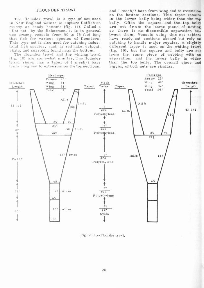
The flounder trawl is a type of net used in New England wat ers to capture flatfish on muddy or sandy bottoms (fig. 11). Called a "flat net" by the fishermen, it is in gene ral use among vessels from 50 to 75 fee t long t hat f ish for various species of flounders. This t ype net is also used for catching industrial fish species, such as red hake , ee lpout, skate, and searobin, found near the bottom.
The flounder trawl and the whiting tr awl (fig. 10) a re somewhat s imilar. The flounder trawl shown has a taper of 1 me s h / 2 ba rs from wing end to extension on the top sec tions,
Headrope Bosom 22'
Stretched Wing 31' Mesh Length Win!! 3 I' Taper Twine
I Total 84'
1 Im2b 33-1/2 ' 4"
1/24
and 1 mesh/ 3 bars from wing end to extens ion on t he bot tom sections. This taper re sults in t he lower belly being wider t han t he top belly. O ft en t he squar e and t he top belly are cut fro m the same piece of n etting so there is no discernible separation be tween them. Vessels using this net s eldom have ready- cut sections aboard but re l y on patching to handle major repai rs. A slightly d ifferent taper is used on the whit ing trawl (fig . 10), but the square and belly a r e c ut from the same piece of we bbing wit h n o separation, and the lower belly is wide r than the top belly. The overall size s and rigging of both nets are similar.
Footrop e Bosom 22' Wing 42' St re t ched
Taper Win!! 42' Length Total 106 '
r Im3b 43-1/ 2
1 Polyethy lene
1 ~ + t 4"
10' --rz:r-t 205 Polyethylene
1 t
1 4"
45-1/2' ~
1
Polyethylene
1 t t
3" 19' Ii36
~ Polyethylene
+ i t
3"
25' 100 All m 1/72
! Nylon
65 l
Figure ll.--Flounder trawl.
20
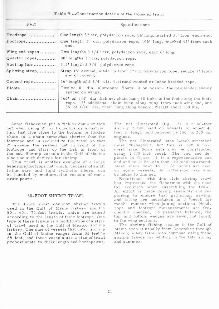
Table 9 . - -Construction details of t he flounder trawl
Part Spe cHic ations
Headrope .. . .•..•........•.
Foot rope . .. ............... .
One length 3" ci r. polydacron rope , 84'10ng, marked 31' from each end.
One length 3" ci r. polydacron rope, 106' long, marked 42' from each end.
Wing end rope s ...•.....•
Quarter ropes ........... .
Two lengths 2 1/ 4" cir. polydacron rope, each 6' long .
80' lengths 3" cir. polydacron rope.
Haul-u p line .....•..•..... 115' length 2 3/ 4" polydacron rope.
Splitting strap ........... . Strap 15' around, made up from 3"cir.polydacron rope, secure 7 ' from end of codend.
C odend rope .•....... ..... 16' lengt h of 2 3/ 4" cir. 4 -strand twisted or loose braided rope.
Floats •. ...•••..•... .......• T welve 8" dia. aluminum floats: 4 on bosom, the remainder evenly spaced on wings.
Chain ..........•........... . 160' of 1/ 4" dia. fish net chain hung 18 links to the foot along the footrope. 12' additional chain hung a long wing from each wing end, and 3 5' of 3/ 16" dia. chain hung along bosom . Weight about 130 lbs.
Some fishermen put a tickler chain on this net when using it for flounders or industrial fish that live close to t he bottom. A tickler chain is a chain somewhat shorter than the footrop e and is secured to the trawl so that it sweeps the seabed just in front of the footrope and stirs up the fish in front of the net. Shrimp vessels in the Gulf of Mexico also use such devices for shrimp.
This trawl is another example of a large headrope / footrope net which, because of small t wine size and light synthetic fibers, can be handled by medium-size vessel s of moderate po we r.
50 -FOOT SHRIMP TRAWL
The three most common shr imp trawls used in the Gulf of Maine fishery are the 50 - , 60-, 70-foot trawls, which are named according to t he length of their footrope. One type of these trawls is a modification of a style of trawl used in the Gulf of Mexico shrimp fishery. The size of vessels that catch shrimp in the Gulf of Maine ranges from 35 feet to 65 feet, and thes e vessels use a size of trawl proportionate to t heir length and horsepower .
21
The net illustrated (fig. 12) is a 60-foot shr imp trawl used on vessels of about 45 feet in length and powered by 150- to 200-hp. engines.
The net illustrated uses 2-inch stretched mesh throughout, but this is not a firm mesh size. Some nets may be constructed us ing 2 1/ 8 -inch me sh. The cod end depicted in Lg ure 12 is a representative cod end and could be less than 110 meshes around. Mesh sizes down to 1 1/ 2 inches are used on some ves sels. An extension may also be added to this net.
Experience with this style shrimp trawl has impressed the fishermen with the need for accuracy when assembling the trawl. An effort is made during assembly and repairing to ensure that gathering, sewing, and lacing are undertaken in a "mesh for mesh" manner when joining sections. Headrope and foot rope measurements are frequently checked. To preserve balance, the top and bottom wedges are sewn, not laced, to the wing se c tions.
The shrimp fishing season in the Gulf of Maine area is usually from December through March; many fishermen continue using these shrimp trawls for whiting in the late spring and summer.

Table 10.--Construction details of the 60 -foot shrimp trawl
Part
Headrope ................. .
Footrope ..... ............. .
Wing end rope s ........ .. Chain .................. .... .
F loats ..................... .
Selvedge lines .......... ..
Quarter ropes .......... .. Haul-up lines . ........... . Splitting strap .......... .. C odend rope ............ ..
Specificat ions
One length 2 1/ 4" cir . polydacron rope, 48 1/4' long , marked 12 1/2' and 7 1/2 ' from each end.
One length 2 1/4" cir. polydacron rope 60 1/2' long: marked 12 1/2 ', 6', and 7' from each end.
Two 5' lengths 2" cir. polydacron rope . 90' - 1/ 4" dia . fishnet chain secured in equal lengths along the footrope.
Weight about 60 Ibs. Adjust to suit. Four 8" dia. aluminum floats. One secured at each corner of the bosom
and at each end of the top wedge . Adjust number to SUlt. I I 2" Cir. polydacron rope of a length equal to stretched mesh leng h
of laceage. Two lengths 2 I 4 " cir. polydacron ropes, 52' long . One length 2 I 4" Clr. polydac ron rope, 41' long. One strap 2 I 4" Cir. polydacron rope, 14' around , hung 6' from codend . One length 2" Cir. 4-strand rope, 14' long.
Note: During assembly of thlS net, particular attention should be given durmg the lacmg together of the sections to make sure that the gathering and lacmg be done on a mesh-for - mesh basIs, so that the webbing IS matched evenly. The wedges may be sewn mto the lower wing sec tlOns rather than laced to these wmgs.
Headroee Foot rope Bosom 8-1/4' Bosom 9-1/Z' Wing ZO' Wing Z5-1/Z' Win!! ZO' 57 Win!! Z5-I/Z' Total 48-1/4' Total tiO-l/Z'
Top Zm Ib 113 Wing IZ-I/Z' IZ-I/Z'
All m
80
6' 97
Lower Wing
Square 44
168
Z48
rop Bottom
Belly Belly
45
110
Cod End 100 All m
Figure 12.--60-Foot shrimp trawl.
22
Melh TWIne
Z" ,ZI Polye thylene
i ZOO
, 36 Polyethylene
Stretch ed L ens th
18-3/4'
1 1
16-1 / 4'
1
1 Z4'
1 i
16-3/4'
1

ACKNOWLEDGMENTS
Published repo rts we re not sufficient sources of information on trawl nets used by U .S. fishing vessels in t he Northwest Atlantic. I had to supplement the published information. The following individual s were particularly helpful: Frank Amero, A. M. Starr et Co., E. Hampton, Conn.; John Cusumano, F.V. Acme, Gloucester, Mass.; Vito Favalora, F.V. Anthony ~ Josephine, G louce ster, Mass. ; Joseph Forbes, GourockBridport-Gundry Ltd., Halifax, Nova Scotia; W. W. Johnson, Industrial Deve lopment Service, Department of Fisheries, Ottawa, Canada; and William E. Wes terbeke and Chnstopher Halligan, Westerbeke Fis hing Gear Co., Boston, Mass.
REFERENCES
BIN S, H. 1959 . Trawling gear . In Hilmar Krist
jonsson (editor) Modern fishing gear
23
of the world, p. 297 -299. Fishing News (Books) Ltd ., London.
FOOD AND AGRICULTURE ORGANIZ ATION OF THE UNITED NATIONS.
1965 . Catalogue of fishing gear designs. Fishing Gear Section, FAO Fisheri~s Division, Food and Agriculture Organlzation of the United Nations, Rome, Italy. FAO Data Sheet N o. 107, FAO Plan No s. 107-A and 107-B, 24 p.
GARN ER, JOHN 1962. How to make and set nets. Fishing
New s (Book s) Ltd., London, 95 p. GARN ER, JOHN, and ALAN GLANVILLE.
1961. Deep sea trawling and wing trawling. Gourock Ropework Co., Ltd., Port Glasgow, Scotland, 106 p.
KNAKE, BORIS O. 1956. Assembly methods for otter-trawl
nets. U.S. Fish Wildl. Serv., Fish. Leafl. 437, 29 p .
MS. #1660
GP 0 9 2 3 · , 29

Created in 1849, the Department of the lnterior--a department of conservation--is concerned with the management, conservation, and development of the Nation's water, fish, wildlife, mineral, forest, and park and recreational resources. It also has major responsibilities for Indian and Territorial affairs.
As the Nation' s principal conservation agency, the Department works to as sure that nonrenewable resources are developed and used wisely, that park and recreational resources ar e conserved for the future, and that r enewable resources make their full contribution to the progress , prosperity, and security of the United States--now and in the future.
[-"111 D ~TATI' DEPART:\IE:\T OF 1 fiE l'\TEIUOR
FISII A,\D \\,ILDLHL ."EI1\'ICE
Bl:REAU OF CI \D[ERClAL FbUERIES
TI-A.' III:, U TU:\, D. C. ~024D
OFFI C I.&.L eUS INES S
Return this sheet to above address, if yo u do
:\OT wish to receive this mater i al 0 , or if
change of address is needed 0 ( in d i ca t e
change),
POSTAGE A:\D FEES PAID U.S. DEPART.\l EXT OF THE IX T E R IO R