Embed Size (px)
Citation preview

FOCUS ON BROADBAND WIRELESS ACCESS
This issue of the Nortel Technical Journal focuses on the solutions and technology innovations Nortel is developing to enable operators and enterprises to go “Beyond 3G” and cost-effectively evolve their networks to support broadband multimedia packet-based wireless services.
Contents
Overview: Technology innovation for wireless broadband access – 1
CDMA2000 1xEV-DO: An easy upgrade path to mobile broadband services – 6
HSDPA and HSUPA: UMTS evolution toward higher-bit-rate data – 13
Nortel’s Wireless Mesh Network solution: Pushing the boundaries of traditional WLAN technology – 18
New enabling technologies: Building blocks for next-generation wireless solutions – 24
WiMAX: Untethering the Internet user – 31
HSOPA: Exploiting OFDM and MIMO to take UMTS beyond HSDPA/HSUPA – 39
Beyond 3G: Technologies that will shape future wireless networks – 43
Newsbriefs – 47
Produced by Nortel’s R&D community

Issue 2, July 2005 The Nortel Technical Journal aimsto provide a vehicle for Nortel’s global R&D community to share with one another and with selected external audiences the wealth of technology innovation under way across our network of laboratories. Published by Office of the Chief Research Officer Guest Editor for this issue Al Javed Executive EditorPeter Carbone Managing EditorVelma LeBlanc The articles in this issue do not necessarily reflect Nortel’s plan of record or commitment to product. The Journal is intended simply as a vehicle through which we can exchange information, share views and perspectives, and expand meaningful dialog within our R&D community and with selected external audiences. We welcome your feedback and look forward to your comments, suggestions for improvement, and ideas for future topics. Please send them by email to:[email protected]
Printed in Canada onrecycled and recyclable paperusing vegetable-based inks

Overview: Technology innovation for wireless broadband accessby John Hoadley and Al Javed
Technology evolution in the access portion of the wireless network is marching forward rapidly, as operators compete fiercely for subscribers and strive to differentiate themselves with the most advanced broad-band multimedia services. Building on its 20 years of wireless technol-ogy leadership, Nortel is driving innovative technology advances across all wireless access technologies, bringing the higher throughput, faster speeds, and greater capacity that operators want, along with the cost-effective evolution paths they need to maximize their existing network investments.
Several years ago, Nortel’s Wireless Technology Lab (WTL) focused its sights on the technology challenges Nortel would have to address to enable its customers to meet the rising demand for broadband mobile data, video, and voice services. The team set the target of achieving ten times the capacity, band-width, and performance that was avail-able at the time. The team also knew it needed to enable the network to ulti-mately deliver the 1-megabit-per-second (Mbit/s) data rates necessary for real-time, truly broadband wireless services – such as interactive 3D gaming, real-time video streaming, large two-way file transfers, and mobile TV – and at a cost level that would make these services af-fordable to a mass market.
Initially, the team thought it was over-shooting the foreseeable, practi-cal demand. However, the WTL has already shown that a ten-fold improve-ment is achievable and has adjusted its target higher. The WTL is today dem-onstrating the delivery of 37 Mbit/s in a 5 MHz carrier.
By all counts, these developments are not over-reaching. Consumers are already starting to gobble up data ser-vices. The biggest market successes to date have been in Korea and Japan, with more than 8 million intense high-speed data users [on next-generation EV-DO (evolution data optimized) networks].
Other examples include Sprint and Verizon, which are aggressively rolling out similar services across the U.S., as well as Cingular Wireless, which is pre-paring for the launch of its high-speed data offering (based on High Speed Downlink Packet Access, or HSDPA, technology) in 2006. Clearly, more and more users have adopted an Internet mindset and a digital nomad lifestyle, and are demanding the same capabilities in wireless that they have come to enjoy in the wired world.
As operators have continued to evolve their networks to meet this demand, the wireless access landscape has become an intricate web of hybrid networks, data overlays, and different access technologies. This complexity, however, can be viewed simply as one stage in the industry’s 20-year evolution (see page 2) – an evolution directed to-ward an ultimate vision of a single, con-verged, packet-based “fat pipe” – one that will carry all wireless multimedia services with high quality and reliability, scale easily to accommodate subscriber growth, and give users whatever band-width they need, simply and cost-ef-fectively.
Convergence in the wireless access network will serve to simplify and lower the costs associated with today’s very complex tangle of networks, which have traditionally carried voice, data, and
video traffic on separate paths, shuttled the traffic using a variety of protocols, and then combined it for delivery to users. Although the technical challenges are unique for over-the-air transmission, this convergence mirrors that occurring in core wireless and wireline networks. (This network convergence, enabled by the 3G IP Multimedia Subsystem (IMS)/Multimedia Domain (MMD) architecture, was discussed in the first is-sue of the Nortel Technical Journal, page 14.) IMS will support applications inte-grating rich voice, video, and messaging into tight bundles developed at low cost within more narrow vertical markets.
This issue of the Nortel Technical Journal highlights the solutions and technology innovations Nortel is devel-oping to enable operators to go “Beyond 3G” and cost-effectively evolve their networks to support the broadband multimedia packet-based services they will need to continue meeting growing user demand.
Beyond 3G: Near- and mid-term evolutionAlready, operators are moving to deploy the next performance improvements. Building on our track record of technol-ogy leadership, Nortel is a prime mover in designing and deploying these tech-nologies, as well as making important technical contributions to the key stan-dards bodies. For instance:• In the CDMA world, we already sup-ply 1xEV-DO solutions to 12 out of the 21 operators that have commercially launched this technology (as of July 2005). With a single-card upgrade, our solution brings near real-time data rates of some 2.5 Mbit/s in the downlink. We are also active in developing 1xEV-DO Revision A, which will significantly
Nortel Technical Journal, Issue 2 1

Wireless technology has come a long way in its relatively short but remark-able history, which began in 1983 with a Chicago-based field trial of the first analog cellular Advanced Mobile Phone System (AMPS). The following is a brief journey through the years, highlighting the different wireless access technolo-gies and their respective evolutionary paths aimed at achieving ever-increas-ing performance and efficiency (see diagram).
1G: Basic mobile voice AMPS was an analog single-carrier system that worked well delivering basic circuit-switched voice, and proved the value of mobility to a previously wired world. The problem with AMPS, though, was that as more subscribers took up the service, the network was unable
Wireless access technologies: A primer
to handle the growth in capacity, and the allocated spectrum – in the 800 and 900 MHz bands – was running out. Operators began to look to digital technology as a way to accommodate the growth, at lower cost, and with higher quality and expanded coverage. This drive for greater capacity and coverage led to the evolution to digital technologies.
2G: The quest for capacity and coverageThe early 1990s saw the introduction of digital cellular technology, with TDMA (time division multiple access), CDMA (code di-vision multiple access), and GSM (Global System for Mobile Communications) sys-tems, all aimed at improving voice quality and system capacity. (Note: the term TDMA refers to both the technique as well as the North American 2G mobile stan-
dard, which is also known as IS-136. GSM systems are also based on the TDMA technique.)
While still circuit-switched-based, digital technology brought greater transmission efficiency, as well as the ability to encode, or compress, voice traffic (in other words, delete the silent intervals, for example, that are part of natural voice conversations).
Digital technology also enabled higher reuse of frequencies. With AMPS systems, a specific frequency could be reused after 12 cells and then, with technology improvements such as sectorization, after seven cells. By contrast, TDMA systems (GSM in Europe) reused frequencies after three cells, and CDMA systems could use all frequencies in all cells. In this way, TDMA achieved three times more capac-ity than AMPS; CDMA more than seven times.
2 Nortel Technical Journal, Issue 2
Evolution of wireless access technologies
1G: Basicmobilevoice
2G: Quest forcapacity andcoverage
3G: Quest for data(higher speeds)
Beyond 3G: Quest for broadband wireless multimedia services
Wirelessmeshnetworks
Low-powernetworks
EmbeddednetworksWiFi
1983 1993 1995 2000 2005 2010
WiMAXOFDM-MIMO
AMPS
WLA
NS
Wid
e ar
ea c
ellu
lar
TDMA(IS-136) CDPD
GSM
CDMA(IS-95)
1xRTT 1xEV-DORev. 0
1xEV-DORev. A
OFDM-MIMO(3GPP2 Evolution)
1xEV-DORev. B MC-DO
GPRS EDGE UMTS HSDPA HSUPA HSOPAOFDM-MIMOOFDM-MIMO
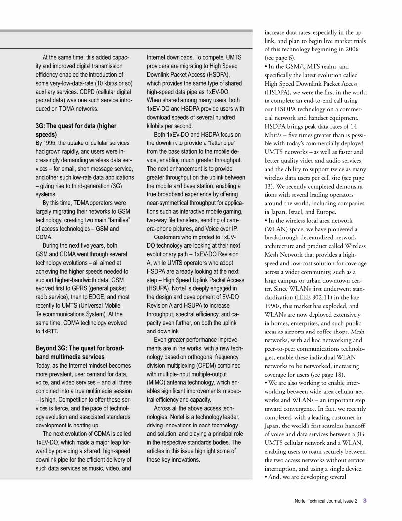
At the same time, this added capac-ity and improved digital transmission efficiency enabled the introduction of some very-low-data-rate (10 kbit/s or so) auxiliary services. CDPD (cellular digital packet data) was one such service intro-duced on TDMA networks.
3G: The quest for data (higher speeds)By 1995, the uptake of cellular services had grown rapidly, and users were in-creasingly demanding wireless data ser-vices – for email, short message service, and other such low-rate data applications – giving rise to third-generation (3G) systems.
By this time, TDMA operators were largely migrating their networks to GSM technology, creating two main “families” of access technologies – GSM and CDMA.
During the next five years, both GSM and CDMA went through several technology evolutions – all aimed at achieving the higher speeds needed to support higher-bandwidth data. GSM evolved first to GPRS (general packet radio service), then to EDGE, and most recently to UMTS (Universal Mobile Telecommunications System). At the same time, CDMA technology evolved to 1xRTT.
Beyond 3G: The quest for broad-band multimedia servicesToday, as the Internet mindset becomes more prevalent, user demand for data, voice, and video services – and all three combined into a true multimedia session – is high. Competition to offer these ser-vices is fierce, and the pace of technol-ogy evolution and associated standards development is heating up.
The next evolution of CDMA is called 1xEV-DO, which made a major leap for-ward by providing a shared, high-speed downlink pipe for the efficient delivery of such data services as music, video, and
Internet downloads. To compete, UMTS providers are migrating to High Speed Downlink Packet Access (HSDPA), which provides the same type of shared high-speed data pipe as 1xEV-DO. When shared among many users, both 1xEV-DO and HSDPA provide users with download speeds of several hundred kilobits per second.
Both 1xEV-DO and HSDPA focus on the downlink to provide a “fatter pipe” from the base station to the mobile de-vice, enabling much greater throughput. The next enhancement is to provide greater throughput on the uplink between the mobile and base station, enabling a true broadband experience by offering near-symmetrical throughput for applica-tions such as interactive mobile gaming, two-way file transfers, sending of cam-era-phone pictures, and Voice over IP.
Customers who migrated to 1xEV-DO technology are looking at their next evolutionary path – 1xEV-DO Revision A, while UMTS operators who adopt HSDPA are already looking at the next step – High Speed Uplink Packet Access (HSUPA). Nortel is deeply engaged in the design and development of EV-DO Revision A and HSUPA to increase throughput, spectral efficiency, and ca-pacity even further, on both the uplink and downlink.
Even greater performance improve-ments are in the works, with a new tech-nology based on orthogonal frequency division multiplexing (OFDM) combined with multiple-input multiple-output (MIMO) antenna technology, which en-ables significant improvements in spec-tral efficiency and capacity.
Across all the above access tech-nologies, Nortel is a technology leader, driving innovations in each technology and solution, and playing a principal role in the respective standards bodies. The articles in this issue highlight some of these key innovations.
Nortel Technical Journal, Issue 2 3
increase data rates, especially in the up-link, and plan to begin live market trials of this technology beginning in 2006 (see page 6). • In the GSM/UMTS realm, and specifically the latest evolution called High Speed Downlink Packet Access (HSDPA), we were the first in the world to complete an end-to-end call using our HSDPA technology on a commer-cial network and handset equipment. HSDPA brings peak data rates of 14 Mbit/s – five times greater than is possi-ble with today’s commercially deployed UMTS networks – as well as faster and better quality video and audio services, and the ability to support twice as many wireless data users per cell site (see page 13). We recently completed demonstra-tions with several leading operators around the world, including companies in Japan, Israel, and Europe. • In the wireless local area network (WLAN) space, we have pioneered a breakthrough decentralized network architecture and product called Wireless Mesh Network that provides a high-speed and low-cost solution for coverage across a wider community, such as a large campus or urban downtown cen-ter. Since WLANs first underwent stan-dardization (IEEE 802.11) in the late 1990s, this market has exploded, and WLANs are now deployed extensively in homes, enterprises, and such public areas as airports and coffee shops. Mesh networks, with ad hoc networking and peer-to-peer communications technolo-gies, enable these individual WLAN networks to be networked, increasing coverage for users (see page 18). • We are also working to enable inter-working between wide-area cellular net-works and WLANs – an important step toward convergence. In fact, we recently completed, with a leading customer in Japan, the world’s first seamless handoff of voice and data services between a 3G UMTS cellular network and a WLAN, enabling users to roam securely between the two access networks without service interruption, and using a single device. • And, we are developing several

Pictured above is a prototype of a Nortel-developed MIMO base station antenna. This particular antenna configuration shows polarization diversity — that is, two arrays of antenna elements that are co-located and oriented orthogonally, at 90 degrees to each other. In other words, all the antenna elements that slope downward comprise one MIMO antenna array; all elements that slope upward form another — effectively combining two antennas in one, giving double the ef-ficiency with the same-sized antenna and increasing coverage, which is particularly beneficial for challenging radio propaga-tion environments, such as dense urban areas. For more, see page 24.
4 Nortel Technical Journal, Issue 2
technology innovations to imple-ment Worldwide Interoperability for Microwave Access (WiMAX) technol-ogy, in addition to our many seminal technical contributions to the main IEEE 802.16 standards body and the WiMAX Forum. WiMAX will not only deliver significant improvements in speed, throughput, and capacity, but will also extend coverage far beyond what is possible with today’s WLAN solutions (see page 31).
On the technology horizonLooking beyond the next few years, the WTL team is working to address the technology challenges associated with achieving the next gains in capacity, coverage, and spectral and power ef-ficiencies. For instance, we are working to:• enable networks to deliver substan-tially more bandwidth to each user;• make systems scalable, so networks can be easily and cost-effectively sized to match subscriber growth; • improve system capacity by an order of magnitude to provide mass applica-tions of these high-bandwidth services through the development of technolo-gies that make more efficient use of already precious wireless spectrum;• reduce systems costs by an order of magnitude to make these high-band-width services affordable; and • make systems easier to use and deploy by reducing the complexity of protocols.
In addressing the challenges, we are building an impressive suite of technol-ogy enablers. Among these are new air interface techniques, advanced spatial processing technologies (multiple an-tenna technology with beamforming), as well as radio-frequency (RF) and hardware innovations (see page 24).
Laying the foundation for the futureIn particular, for the past six years we have pioneered a new air interface tech-nology that combines an antenna pro-cessing technique called multiple-input multiple-output (MIMO) with a modu-
lation scheme called orthogonal fre-quency division multiplexing (OFDM) (see page 26).
In spectral efficiency and capacity circles, the OFDM-MIMO combo is a blockbuster, with the potential to lay the foundation for the data rate and capacity gains that will be needed for years to come.
In this area, we have significant leadership – from innovations at both the physical and MAC (Media Access Control) layers, to extensive expertise in measuring, understanding, and modeling its use in various propaga-tion environments, to a string of world firsts. For instance, we were the first to demonstrate an OFDM-MIMO system, achieving data transmission speeds 25 times faster than today’s commercially deployed UMTS networks and five times faster than HSDPA.
Our first application of OFDM-MIMO is in our WiMAX technology solution, discussed earlier.
OFDM-MIMO is also being con-sidered as an access technology for the evolution of both CDMA and UMTS networks. The 3GPP2 (Third Generation Partnership Project 2) stan-dards bodies are discussing the incorpo-ration of OFDM-MIMO in the evolu-tion of 1xEV-DO/EV-DO Revision A networks. As well, the 3GPP (Third Generation Partnership Project) is considering the OFDM-MIMO evolu-tion of HSDPA/HSUPA networks – an evolution that Nortel has coined High Speed OFDM Packet Access (HSOPA) (see page 39). In both of these areas, we are making important contributions to standards development, as well as solv-ing the technology challenges involved with deployment in real-world environ-ments.
Future challengesUntil network evolution reaches the point of true and full convergence, and wireless access networks can support ubiquitous – and affordable – delivery of super-speed multimedia services, the industry will remain an intricate web of

Nortel Technical Journal, Issue 2 5
hybrid systems, all at various stages of evolution.
This transition itself presents a set of unique challenges that the industry will need to address.
One of these challenges is heteroge-neous network management, to provide uniformity of services across what will likely be a patchwork of multiple access technologies. A CDMA network, for example, might have 1xEV-DO Rev. A for a dense city area where demand for super-fast data services is highest, while other less dense areas with less demand might have 1xRTT or 1xEV-DO Rev. 0 capabilities. The network, then, needs to be able to adapt a user’s service to match the capabilities of different technology domains as users roam throughout a network. A user receiving, say, full-motion full-color video service in the city core would receive only black and white, somewhat jerky video as they traveled out of the city into suburban or rural areas. While not optimal, this change in service capability would be far preferable to users than being dropped altogether.
Another challenge will be to give networks the capability to handle differ-ent modes of operation, such as ad hoc networking, peer-to-peer communica-tions, multi-hop networking, multicast, and broadcast.
Also emerging are new applica-tions for wireless technology beyond wide area and local area networks. Micro-miniaturization technologies are enabling wireless capability to be em-bedded everywhere. The continued and growing application of 802.11 WiFi to connect such devices as personal digi-tal assistants (PDAs), laptops, mobile phones, and cameras into wireless per-sonal area networks – is already wide-spread. Home networking, low-power sensor and actuator networks, and embedded networks are also emerging. The final article in this issue (page 43) offers a look at how some of these new opportunities could unfold.
To help solve these future challenges, Nortel is enhancing its research and
development efforts on several fronts as well as working closely with several lead-ing universities around the world and forming partnerships with other lead-ing technology developers. In this way, Nortel maintains its firm hold on the leading edge of technology. Moreover, our engineers and researchers, who already hold some 1,500 wireless tech-nology patents, with more filed every day, are bringing unmatched experience, understanding, and innovation across all wireless access technologies, and they will continue to play a key role in defin-ing and developing the evolution paths that wireless operators will need – today and into the future.
John Hoadley recently assumed the role of Leader, Wireless Advanced Technology, in addition to his role as Leader, Next-Generation Wireless Access Business Development. Al Javed, a driving force behind Nortel’s wireless technology leadership, recently announced his plans to retire after 28 outstanding years with the company. Al was formerly Leader of Wireless Advanced Technology and is currently on special as-signment, leading a number of projects within the Chief Research Office.
Verizon Wireless in the U.S., Telstra in Australia, Eurotel in the Czech Republic, BellSouth International and Smartcom in Chile, and Pelephone in Israel all have something in common – they are among the 12 of 21 operators worldwide (as of July 2005) that have launched code division multiple access (CDMA) 1xEV-DO (evolution data optimized) service commercially to have chosen Nortel’s solution. In fact, Nortel has been deploying 1xEV-DO with customers for nearly three years, with trials held throughout 2002 and South America’s first commercial 1xEV-DO deployment in Vesper’s network in Sao Paulo, Brazil in March 2003, followed by a major deployment in September 2003 with Verizon that covered the city of San Diego and surrounding area.
The evolutionary 1xEV-DO technology supports higher data rates and three to six times more users per cell than existing CDMA2000 1X 3G wireless systems, enabling these operators to generate new streams of revenue from an expanded applications services set – beginning with mobile
CDMA2000 1xEV-DO: An easy upgrade path to mobile broadband servicesby Vish Nandlall
Specified by the Third Generation Partnership Project 2 (3GPP2), CDMA2000 1xEV-DO is optimized for packet data traffic and incorporates a number of technologies that significantly improve spectral efficiency and data throughput. Nortel is a leader in 1xEV-DO standards development and currently supplies CDMA2000 1xEV-DO wireless solutions to 12 of 21 operators (as of July 2005) that have commercially launched 1xEV-DO around the globe. Unlike some competitors’ solutions that require deployment of new base stations, Nortel’s 1xEV-DO solution can be easily implemented with a single card addition to an existing Nortel CDMA Metro Cell base transceiver station, providing an easy upgrade path and investment protection for CDMA2000 operators to roll out mobile broadband services.
web browsing and extending into interactive gaming, mobile music, and a variety of IP services, including Voice over Internet Protocol (VoIP) and high-speed file transfers.
What differentiates Nortel’s 1xEV-DO solution is that it can be implemented with just a single card addition to a Nortel CDMA Metro Cell base transceiver station (BTS), of which more than 60,000 are deployed worldwide today. The Metro Cell platform allows scalable growth of up to nine 1xEV-DO frequency carriers – which will support up to 27 carrier sectors, or nine carriers in each of three sectors – to provide customers with the confidence that they can continue to increase data capacity within their current infrastructure footprint (Figure 1).
The Nortel 1xEV-DO backhaul physical interface includes options for 100BaseT Ethernet, in addition to unchannelized T1/E1, which allows operators to take advantage of IP backhaul to optimize costs based on their requirements and flexibility. By integrating IP routing functionality in
the 1xEV-DO single-module Metro Cell upgrade, Nortel’s solution also can reroute around failures or rehome to other network resources, increasing system reliability. As well, the Nortel 1xEV-DO Radio Network Controller (RNC) offers industry-leading capacity to home up to 200 BTSs. With fewer RNCs required in a given network deployment, Nortel’s solution delivers both CapEx and OpEx savings for operators.
CDMA evolution1xEV-DO is the latest evolution of CDMA IS-95, a concept for mobile radio introduced by Qualcomm, Inc. in 1990, at a time when the U.S. cellular industry was selecting its first digital mobile telephone standard. CDMA increased cellular capacity significantly by allowing multiple users to share the same spectrum through the use of direct sequence spread spectrum (DSSS) transmitters. DSSS transmitters “spread” a narrowband information signal across a wide band of frequencies using a spreading code that is applied to the transmitted information stream.
Third-generation CDMA 1X networks (IS-2000), a technology which Nortel was the first in the industry to trial in March of 2000, improved upon first-generation IS-95 by adding fast power control to reduce the variability of the received signal strength in slow to moderate fading conditions. Fast power control significantly reduces the power required to compensate for fading conditions on the IS-95 downlink and evens out the capacities of the uplink and downlink.
6 Nortel Technical Journal, Issue 2

This improvement effectively doubles the subscriber density per radio carrier.
The latest evolution, CDMA 2000 1xEV-DO, was introduced to handle significantly higher data rates on the downlink (for web browsing, for example) and to efficiently implement a packet data service, which was constrained because voice and data in traditional CDMA systems were carried over the same radio frequency (RF) carrier. 1xEV-DO dedicates an RF carrier to data, allowing operators to segregate data service from their installed 1X voice systems. (For more on the CDMA evolution, see www.cdg.org.)
1xEV-DO has been defined by the Third Generation Partnership Project 2 (3GPP2), a collaboration of several standards bodies from around the world that is developing technical specifications and a framework for third-generation CDMA wireless networks. Specifically, 3GPP2 has defined a data-only version of CDMA called CDMA2000 High Rate Packet Data (HRPD) – more commonly referred to as 1xEV-DO. The “1x” prefix stems from its use of 1 times the 1.2288 mega chips per second (Mcp) spreading rate of a standard IS-95 CDMA channel. “EV” emphasizes that it is an EVolutionary technology that builds and improves on CDMA 2000 technology. The “DO” (data optimized) suffix indicates that 1xEV-DO is designed to efficiently transfer data. The 3GPP2 technical specification for 1xEV-DO is C.S0024-0, and has been published as a North American standard by the Telecommunications Industry Association (TIA) as IS-856.
In the near-term, 1xEV-DO is evolving through two major revisions:• 1xEV-DO Revision 0, currently being deployed, provides near real-time data rates of up to 2.5 Mbit/s in the forward link (downlink), and 153.6 kbit/s in the reverse link (uplink). • 1xEV-DO Revision A increases data rates to up to 3.1 Mbit/s in the forward
link and, more significantly, to 1.8 Mbit/s in the reverse link, to better enable interactive, real-time, and delay-sensitive applications, such as VoIP, video conferencing, mobile gaming, mobile music, and high-speed file transfers. Nortel is planning live market trials of CDMA 1xEV-DO Revision A technology with several CDMA service providers beginning in 2006.
Nortel has been a major contributor to the development of both the 1xEV-DO Revision 0 and Revision A standards in 3GPP2. For example, Nortel has proposed key concepts to the standards that improve packing efficiency for the HRPD air interface, such as multi-user packets, and has been instrumental in the development process of the 1xEV-DO Revision A physical layer.
With just 1.25 MHz of paired spectrum required to start deploying a 1xEV-DO network, the market uptake of 1xEV-DO technology by operators has been favorable. The Nortel 1xEV-DO solution can be launched in any frequency band between 450-3500 MHz or in bands currently used for wireless voice systems, such as the PCS (1900 MHz) and cellular (850 MHz) bands. (PCS and cellular are especially well suited because they allow an operator to lease or reuse existing CDMA cell sites.)
1xEV-DO Revision 0While the 153 kbit/s reverse link remains relatively unchanged from CDMA 2000, peak data rates in the forward link in 1xEV-DO are 16 times higher. This makes 1xEV-DO similar to most cable modems where upload and download speeds are asymmetrical. In 1xEV-DO Revision 0, the download rates from the base station to the mobile user vary from 38.4 to 2,457.6 kbit/s, while upload speeds from the mobile to the base station range from 9.6 to 153.6 kbit/s. To achieve a higher rate, the forward link in 1xEV-DO serves data users in time-multiplexed rather than code-multiplexed mode.
1xEV-DO also shares another characteristic with cable modems – available bandwidth on the forward link is shared by all users. If there is only one active user, all the bandwidth is available to that user. However, as more users enter the system, data rates decline. Roughly speaking, the number of subscribers who are receiving data at the same time in the same sector determines the system load. For instance, when two subscribers are downloading simultaneously at a fixed link rate of 1.2 Mbit/s, the actual data rate they experience will be around 600 kbit/s. This characteristic may appear to be a significant disadvantage, but because of the bursty nature of data traffic, the data user on average will experience few delays unless a system is highly loaded.
A distinct feature of the 1xEV-DO system is that a base station always transmits at its maximum power. This makes full use of the RF spectrum capacity and implies that the data rate selection is determined exclusively by the channel conditions. Therefore, the forward link rate depends on the interference-plus-noise at the subscriber’s location. Interference and noise exhibit significant variation, which is an inherent characteristic of all wireless systems and occurs primarily because of variations in RF propagation loss, building penetration loss, fading effects, and co-channel interference.
Under the hood1xEV-DO compensates for these changing channel conditions and achieves high spectral efficiency through a number of techniques that make it ideally suited for forward link data transmission. These techniques include:• long-range channel estimation and rate prediction;• hybrid automatic repeat request (HARQ) with incremental redundancy; • turbo coding; and• fast scheduling of packet transmission that exploits multi-user diversity in a
Nortel Technical Journal, Issue 2 7
8 Nortel Technical Journal, Issue 2
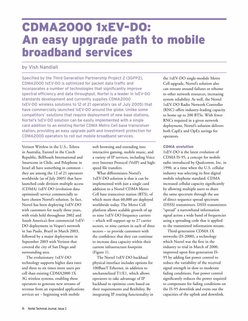
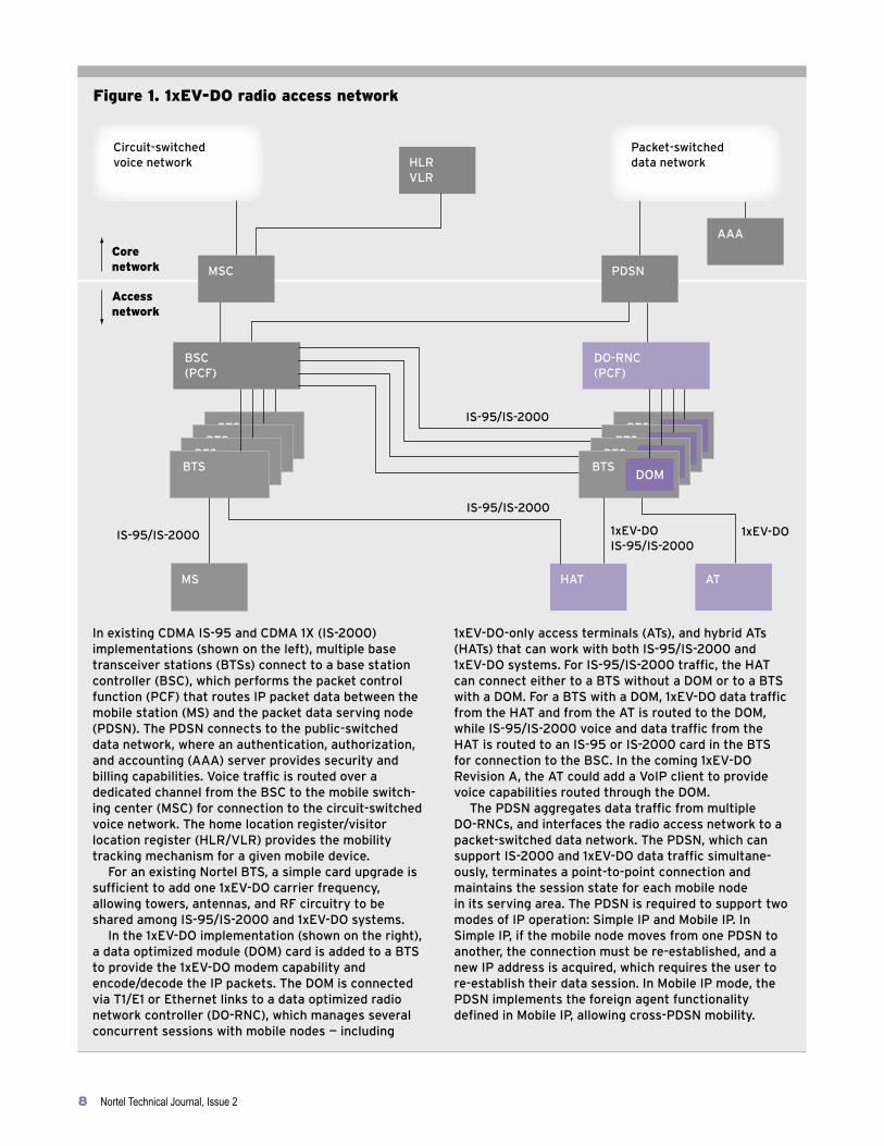
Figure 1. 1xEV-DO radio access network
Circuit-switchedvoice network
Core network
Accessnetwork
Packet-switched data networkHLR
VLR
AAA
PDSNMSC
DO-RNC(PCF)
In existing CDMA IS-95 and CDMA 1X (IS-2000) implementations (shown on the left), multiple base transceiver stations (BTSs) connect to a base station controller (BSC), which performs the packet control function (PCF) that routes IP packet data between the mobile station (MS) and the packet data serving node (PDSN). The PDSN connects to the public-switched data network, where an authentication, authorization, and accounting (AAA) server provides security and billing capabilities. Voice traffic is routed over a dedicated channel from the BSC to the mobile switch-ing center (MSC) for connection to the circuit-switched voice network. The home location register/visitor location register (HLR/VLR) provides the mobility tracking mechanism for a given mobile device. For an existing Nortel BTS, a simple card upgrade is sufficient to add one 1xEV-DO carrier frequency, allowing towers, antennas, and RF circuitry to be shared among IS-95/IS-2000 and 1xEV-DO systems. In the 1xEV-DO implementation (shown on the right), a data optimized module (DOM) card is added to a BTS to provide the 1xEV-DO modem capability and encode/decode the IP packets. The DOM is connected via T1/E1 or Ethernet links to a data optimized radio network controller (DO-RNC), which manages several concurrent sessions with mobile nodes — including
1xEV-DO-only access terminals (ATs), and hybrid ATs (HATs) that can work with both IS-95/IS-2000 and 1xEV-DO systems. For IS-95/IS-2000 traffic, the HAT can connect either to a BTS without a DOM or to a BTS with a DOM. For a BTS with a DOM, 1xEV-DO data traffic from the HAT and from the AT is routed to the DOM, while IS-95/IS-2000 voice and data traffic from the HAT is routed to an IS-95 or IS-2000 card in the BTS for connection to the BSC. In the coming 1xEV-DO Revision A, the AT could add a VoIP client to provide voice capabilities routed through the DOM. The PDSN aggregates data traffic from multiple DO-RNCs, and interfaces the radio access network to a packet-switched data network. The PDSN, which can support IS-2000 and 1xEV-DO data traffic simultane-ously, terminates a point-to-point connection and maintains the session state for each mobile node in its serving area. The PDSN is required to support two modes of IP operation: Simple IP and Mobile IP. In Simple IP, if the mobile node moves from one PDSN to another, the connection must be re-established, and a new IP address is acquired, which requires the user to re-establish their data session. In Mobile IP mode, the PDSN implements the foreign agent functionality defined in Mobile IP, allowing cross-PDSN mobility.
BSC(PCF)
BTSBTS
BTSBTS
BTSDOMBTS
DOMBTSDOMBTS
DOM
1xEV-DO
IS-95/IS-2000
IS-95/IS-2000 1xEV-DOIS-95/IS-2000
HAT ATMS
IS-95/IS-2000

fading RF environment.Long-range channel estimation
and rate prediction are used to effectively shape the transmission to optimally transfer data at a requested data rate under varying channel conditions. The net effect is to increase average cell throughput.
Long-range rate prediction of fading channel is based on current and past estimates of the strength of the pilot signals received by the mobile from all surrounding base stations. A separate channel is used to carry the pilot signal strength measurements (which in turn are used for handoff triggers).
The channel-state information is fed to a prediction algorithm, which then transforms the subscriber information stream with an appropriate modulation to resist errors due to RF channel limitations. One of three types of modulation is used: quaternary phase shift keying (QPSK), 8-level PSK (8-PSK), or 16-level quadrature amplitude modulation (16 QAM). 16 QAM is used for the higher data rates, while QPSK and 8-PSK are used for lower data rates. In addition, channel coding is adapted to increase the average cell throughput, and it is the combination of modulation and coding adaptation that is the prime reason for the peak rate efficiencies in 1xEV-DO.
HARQ is theoretically the most efficient way to provide reliability over a link. It is defined as the joint use of ARQ and some type of forward error correction code (in the case of 1xEV-DO, turbo coding is applied). HARQ with incremental redundancy has proven to be especially useful in situations where accurate channel prediction is not possible – for example, at high mobile speeds or when interference is highly variable.
HARQ with incremental redundancy is accomplished by transmitting the encoded packets using multiple time division multiplex (TDM) slots interlaced by four slots, and allowing early termination based on partial reception of the
Nortel Technical Journal, Issue 2 9
encoded packet, i.e., when successful reception is signaled through the ACK (acknowledgement) channel. This approach is possible because packets are encoded in multiple slots with enough redundancy (through turbo coding) to make successful reception of one slot sufficient for decoding the whole packet (although the reception of each successive slot improves the likelihood of successful decoding after combining). The four-slot interlacing provides the time necessary for the mobile to attempt decoding and to signal the status back to the base station over the ACK channel.
Turbo coding is one of the most significant recent developments in the area of error control coding. Turbo coding is a technology used to protect the digital information from noise
and interference and to reduce the number of bit errors on the wireless channel (Figure 2). Forward error correction is mostly accomplished by selectively introducing redundant bits into the transmitted information stream. These additional bits allow detection and correction of bit errors in the received data stream, enabling more reliable information transmission. The powerful turbo coding scheme in 1xEV-DO produces a block code that can perform to within a fraction of a decibel of the Shannon limit (the theoretical limit of maximum information transfer rate over a noisy channel).
Turbo codes can be used either to increase available bandwidth (without increasing the power of a transmission), or to decrease the
Figure 2. Turbo coding
Turbo coding is an error correction coding scheme that in the case of 1xEV-DO is used to increase the data throughput for a given transmitting power. Turbo coding is a key to allowing mobile devices to handle video, graphics, and other high-bit-rate multimedia and data communications over the noisy channels typical of wireless communications. In turbo coding, the data input is divided into strings of bits and fed in parallel to two convolutional encoders where extra bits — called parity bits — are added to each string to help identify and correct errors at the receiving end. The second encoder, however, receives the string of bits in a different order, scrambled by the pseudo-random interleaver. The interlever’s main purpose is to reduce the multiplicity of error
events at the minimum bit distances (called “spectral thinning”), and it is the key to the performance of turbo coding. The two encoders’ output refers to the same data, but the bits are arranged in a different order, and the two encoders can work together synergistically to improve the likelihood of error-free communications. Some of the symbol sequences (each symbol represents one, two, or more bits of transmission rate data) output by the encoders are then repeated to add redundancy, and punctured with additional information, such as power control, to yield high-rate codes before being sent to the radio frequency (RF) transmitter, where the digital signal is converted to analog for transmission to the mobile station.
Data
Pseudo-random interleaver
Convolutional encoder
Convolutional encoder
Symbolrepetition and puncturing

expected to be published in Q1 2006. Nortel has led the discussion within 3GPP2, presenting an evolution framework document outlining the potential implementation paths of an MC-DO system.
Compared to a 1xEV-DO Revision A network that uses a single carrier and single channel assignment per subscriber, the bandwidth utilization and performance (in terms of throughput and blocking) of an MC-DO network should improve significantly – although traffic and interference-adaptive resource allocation schemes will be necessary to deliver reasonable performance for large-bandwidth users. In this area, Nortel will be able to apply its tremendous heritage in radio technology, where, for instance, we’ve already developed radio resource management features such as multi-carrier transmit allocation for our CDMA 2000 product.
In the current 1xEV-DO radio network, each user is assigned one
channel at a time and the goal of resource allocation is to maximize the number of users that a network can support simultaneously. MC-DO, on the other hand, will enable a set of carriers (frequencies) to be allocated to a particular subscriber and their respective forward link channels to be decided dynamically, based on the service request and the present load and/or interference power in the network.
This adaptive radio bandwidth assignment will enable a more efficient allocation of radio resources to support different types of users whose bandwidth requirements can vary substantially. Increasingly, wireless users want access to a diverse set of data and multimedia applications with different bandwidth demands, as well as to real-time applications (such as gaming and video) where minimum performance guarantees are required in terms of bandwidth, delay, and bit error rate.
As shown in the diagram, in MC-DO
The next evolution being proposed beyond 1xEV-DO Revision A is Multi-Carrier 1xEV-DO (MC-DO), an adaptive radio bandwidth and carrier assignment scheme that provides the flexibility to address the growing variation in the bandwidth needs of different subscribers. This user assignment scheme, combined with dynamic radio frequency (RF) carrier allocation, will promote diversity gain in the sharing of the 1xEV-DO fat pipe resources – enabling greater achievable bit rates per user and improving the trunking efficiency of the RF carriers to provide operators an increased return on their investment. Given that MC-DO maintains full compatibility with 1xEV-DO Revision A, this technology will enable a smooth evolution to higher per-user throughputs and peak data rates through reuse of existing infrastructure.
MC-DO is forming the basis for 1xEV-DO Revision B, which is currently under definition in the Third Generation Partnership Project (3GPP2) and is
Multi-Carrier 1xEV-DO: Meeting the bandwidth needs of different users
10 Nortel Technical Journal, Issue 2
1.25 MHz
carrier
1.25 MHz
carrier
1.25 MHz
carrier
1.25 MHz
carrier
1. Hyper data mode (gaming)
2. Balanced speed mode (file sharing)
FL
RL
User B:Type 3
User A: Type 1
FL
RL
FL - Forward link RL - Reverse link
Multi-Carrier 1xEV-DO carrier assignments
3. Economic mode (voice)
FL
RL
4. Entertainment mode (movie)
FL
RL

the forward packet data channel is divided into time slots, as it is in 1xEV-DO. However, in each time slot, the subscriber equipment or base station can use any of the several frequencies available, allowing the available spectrum to be divided into a set of carriers. Each carrier can be used in any time slot by the communicating equipment. The key is that no carrier or time slot is assigned to any particular subscriber equipment, so that nearly all carriers and time slots are available as a pool to everyone, giving subscribers high peak and average bit rates on demand. Two or three carriers per user is expected to be the practical implementation scenario.
Application requirements and resource requests govern the choice of the carrier or time slot. For example, user A, who requires the speed and performance of hyper data mode for a gaming application, is assigned three forward link (FL) carriers or time slots; while user B, who requires the low-cost communications of the economic mode for a voice call, is assigned one forward link carrier or time slot. Other users could be assigned the appropriate number of carriers or times slots for balanced speed mode communications (such as file sharing) or for entertainment mode (such as movies). In the reverse link (RL), larger or smaller per-user bit rates can be assigned as required – larger for hyper data mode and balanced speed mode, and smaller for entertainment mode or economic mode.
Nortel Technical Journal, Issue 2 11
amount of power used to transmit at a certain data rate. 1xEV-DO uses the former mode. The key insight for turbo codes is the realization that instead of just producing a stream of binary digits from the signal that it receives, the front end of the decoder can be designed to produce a likelihood measure for each bit.
Fast scheduling of packet transmission on the forward link is enabled by the use of scheduling algorithms that exploit multi-user diversity in a fading environment to increase data throughput.
In 1xEV-DO, the channel state is periodically measured by the user’s mobile and fed back to the base station once every 1.667 milliseconds (ms). Each mobile constantly reports to the base station its “instantaneous” channel capacity, i.e., the rate at which data can be transmitted if the mobile is scheduled for transmission. The scheduling algorithm takes advantage of the channel variations by giving some form of priority to users with instantaneously better channels – choosing a user whose channel becomes favorable for a short period of time during an “up-fade,” while delaying data transmission to a user who is temporarily in a “down-fade” relative to its average condition. The gain achieved through this channel-state dependent scheduling is called the multi-user diversity gain.
1xEV-DO Revision AApproved by the 3GPP2 Technical Specification Group (TSG-C) in April 2004, 1xEV-DO Revision A supports higher peak data rates of 3.1 Mbit/s on the forward link and up to 1.8 Mbit/s on the reverse link – 12 times the 153 kbit/s reverse link rate of Revision 0. Originally, it was generally believed that future wireless networks would be highly asymmetric, with much larger capacity requirements necessary on the forward link for web browsing. However, traffic is not likely to be as asymmetric as previously thought,
as services such as VoIP, mobile gaming, and mobile music, as well as uploads from consumer devices such as streaming-video camcorders and camera phones, challenge this assumption. In addition to higher reverse link speeds, Revision A will allow operators to manage various users and applications with different levels of priority, making it possible to offer tiered services and multiple pricing options for different types of services and applications.
The majority of the improvements in Revision A target the efficient carriage of VoIP (as well as push-to-talk traffic), where packet size is typically small and reduced latency (delay) is paramount. Nortel has established a leadership position in harnessing and driving the standardization of the Revision A capabilities, as well as in the definition of a VoIP-capable wireless system based on 1xEV-DO Revision A. Current Nortel simulations show that Revision A would provide similar voice (VoIP) capacity as CDMA2000 1X. Nortel is planning VoIP demonstrations and early customer lab VoIP testing in 2006, and expects to have results from various trials by the early 2007 timeframe.
To support such applications as VoIP, 1xEV-DO Revision A offers both capacity and quality of service (QoS) enhancements relative to Revision 0. The key contributors to capacity improvements include:• serving sector selection, which allows the mobile to quickly hand off from one BTS to another, improving cell edge interference caused by “cell dragging” (which occurs when a mobile enters a BTS coverage area while still being served from another BTS). The net effect is an increase in average sector throughput, as well as a decrease in handoff delay; and • reverse link HARQ and reverse link adaptive modulation, which are essentially applying the 1xEV-DO Revision 0 forward link innovations to the reverse link to increase the peak
12 Nortel Technical Journal, Issue 2
data rates. The key contributors to QoS
support with improved latency characteristics are:• forward link packet size granularity, which introduces four new packet sizes (128, 256, 512, and 5129 bits), improving packing efficiency and reducing padding requirements to reduce response times;• radio link protocol (RLP) QoS enhancements, which enable multiple intra-user sessions, each supporting a different QoS profile, as well as enhancements for real-time applications. 1xEV-DO Revision A introduces the concept of assigning a user multiple simultaneous RLP sessions, each mapped to a different QoS profile, in order to simultaneously support different user application requirements (such as low latency, best effort, etc.). Support is also provided to disable the RLP ARQ protocol to conserve bandwidth for delay-sensitive applications;• reverse link support of short frame sizes, which provides packing efficiency improvements, allowing physical layer packets to be transmitted in increments of 6.67 ms, or a subframe, instead of 26.67 ms (a Revision 0 frame duration), to improve capacity for short-packet-size applications, such as VoIP; and• forward link multi-user packets, which allow multiple users to be scheduled simultaneously, improving efficiency and reducing packet latency for delay-sensitive applications for increased throughput. This improvement is achieved through grouping information from multiple users into a single physical layer packet.
Beyond Revision A, there are already plans to push the 1xEV-DO technology even further. Discussions are under way to include improvements for 1xEV-DO Revision B that will likely combine multiple carriers to provide a multi-megabit downlink (see page 10), and will potentially employ burst-mode uplink improvements. Other
improvements being considered include the addition of orthogonal frequency division multiplexing (OFDM) and multiple-input multiple-output (MIMO) capabilities, which will drive even greater throughput increases (see page 26).
Vish Nandlall is Chief Architect, CDMA Access.

Nortel Technical Journal, Issue 2 13
In June 2005, Nortel became the first wireless infrastructure supplier in Japan (based on published announcements) to demonstrate Universal Mobile Telecommunications System (UMTS) 14 Mbit/s High Speed Downlink Packet Access (HSDPA) wireless data trans-mission – five times faster than today’s commercially deployed UMTS wire-less networks. The demonstration was conducted in a trial with BB Mobile, a company in the SOFTBANK Group, Japan’s number-one provider of broad-band infrastructure services. Soon after, the two companies completed what is believed to be the world’s first seam-less handoff of voice and data services between a third-generation cellular net-work operating on the 1.7 GHz radio frequency band and a wireless local area network.
The demonstration followed close on the heels of Nortel’s completion in May 2005 of the industry’s first HSDPA trial in Israel, with Partner Communications, which demonstrated advanced wireless and multimedia broadband services, including high-speed music transfers
HSDPA and HSUPA:UMTS evolution toward higher-bit-rate databy Denis Fauconnier
High Speed Downlink Packet Access (HSDPA) is a new UMTS packet air interface that delivers higher data rates, lower latency, and higher capacity to support mobile broadband services such as web browsing, video streaming, mobile gaming, and mobile music, and in the future Voice over Internet Protocol (VoIP). HSDPA will be complemented by High Speed Uplink Packet Access (HSUPA), which will enable two-way high-speed communications between the base station and mobile de-vices. Nortel is among the first to bring HSDPA to market, leveraging its deep-rooted understanding of the standards gained through early involvement in the Third Generation Partnership Project (3GPP), its experience in deploying 1xEV-DO and W-CDMA networks, and its imple-mentation of the technology via a fast and economical software-only upgrade that protects operators’ existing investments.
(MP3), DVD-quality video streaming, and downloads of large e-mail attach-ments over a live cellular network in Tel Aviv.
The successful demonstrations in Japan and Israel are the latest in a se-ries of milestones validating Nortel’s HSDPA technology. Nortel’s UMTS equipment was first demonstrated to be HSDPA-ready in June 2004, suc-cessful HSDPA trials took place in October 2004, and a system using commercial infrastructure and chipsets was demonstrated in January 2005. In addition to BB Mobile and Partner Communications, Nortel is working in 2005 on trials and deployments with a number of other global operators, in-cluding mmO2, Orange (at the 3GSM Congress in Cannes, France), Vodafone (at CeBIT 2005 in Hanover, Germany), and mobilkom Austria, the largest mo-bile operator in Austria.
HSDPA developmentDefined in the Third Generation Partnership Project (3GPP) Release 5, HSDPA is a new UMTS air interface
optimized for high-bit-rate packet data transmission. (3GPP is a collaboration of standards bodies from around the world developing technical specifica-tions and a framework for third-genera-tion GSM/UMTS wireless networks.)
HSDPA’s introduction inside the original UMTS Radio Access Network (UTRAN) Release 99 architecture has been extremely smooth. Nortel’s base transceiver stations (BTSs) – Node Bs in the 3GPP specifications – support HSDPA via a simple software upgrade, thereby protecting our customers’ exist-ing investments. HSDPA is also back-wards-compatible, enabling both pre-HSDPA and HSDPA mobile terminals – identified as user equipment (UE) in the 3GPP specifications – to co-exist in a network.
HSDPA, which is five times more spectrally efficient than traditional UMTS deployments, offers significant benefits. One, it boosts network capac-ity to carry up to three times more data traffic and support up to twice as many data users per cell, cutting operating costs for service providers. And, two, it provides download speeds compa-rable to fixed line broadband solutions (such as ADSL) and reduces latency from about 100 milliseconds (ms) to as low as 65 ms, opening up access to an increasing range of real-time wireless broadband applications, such as web browsing, video streaming, mobile gam-ing, and mobile music for end users. HSDPA, in fact, was designed to sup-port all IP services except voice, which will be supported in 3GPP Release 6. Release 6 specifies High Speed Uplink Packet Access (HSUPA), which is dis-

cussed later in this article. Nortel, through chairmanship in
various 3GPP groups, rapporteurship of key items, and technical contributions, is one of the leaders in defining the key elements of the UMTS HSDPA/HSUPA evolution. While Nortel is implementing products according to the standard, it is also leveraging its expertise in the innovative application of technology in those areas left imple-mentation-dependent by the standard, most notably in the area of advanced scheduling algorithms.
Nortel product development is being shaped by a number of 3GPP-specific HSDPA technologies, including: • a new shared downlink packet data transport channel; • a fast scheduler for multiplexing packets for transmission over the radio interface; • hybrid automatic repeat request (HARQ) retransmission schemes for error recovery; and• adaptive modulation and coding, with a new 16 quadrature amplitude modu-lation (16 QAM) scheme for high data rates.
Shared downlink channelHSDPA is essentially a new “fat pipe” in every wireless UMTS network cell for communication on the downlink from the BTS to mobile terminals.
This pipe comprises two HSDPA-specified radio channels that collectively form the shared downlink channel:• high speed downlink shared channel (HS-DSCH), which carries the data blocks; and • high speed shared control channel (HS-SCCH), which carries the associ-ated signaling necessary for a mobile terminal to decode the data blocks, as well as some information on the HARQ error recovery protocol.
Because this shared data channel is optimized for packet data transmission, an associated dedicated channel can be allocated to an HSDPA-capable mobile terminal to carry voice and video ser-vices, typically to the public switched
telephone network or integrated services digital network (ISDN). As noted earli-er, however, VoIP over the shared chan-nel will be included in 3GPP Release 6, expected to be completed in 2006.
The shared downlink data channel overcomes the limitations of the Release 99 architecture, which was designed for dedicated data channels, with the radio network controller (RNC) connecting the BTSs. In Release 99 implementa-tions, because a mobile terminal can be served by multiple cells, soft handover is required and physical channels are ter-minated in the RNC. (In soft handover,
the connection to the new cell is made before the mobile leaves the current cell, in contrast to a hard handover, where the connection to the current cell is interrupted before the connection to the new cell is made.)
As a result, in Release 99, all Layer 2 transport protocols must reside in the RNC – in particular, downlink packet scheduling functions and the repetition mechanism for error recovery – which slows these operations and limits data rates. With HSDPA, packet data is scheduled for transmission directly by the BTS rather than the RNC, and a
14 Nortel Technical Journal, Issue 2
Figure 1. HSDPA network architecture
High Speed Downlink Packet Access (HSDPA) has been introduced with minimal impact on the existing UMTS Radio Access Network Release 99 architecture. As before, in the radio network controller (RNC), shown on the right, the IP packets are segmented in the radio link control (RLC) layer and multiplexed in the MAC-d layer. In the Release 99 implementation, the segmented IP packets are sent to the base transceiver station (BTS) for radio transmission directly on a dedicated physical channel to the mobile. In the HSDPA
implementation, the IP packets are assembled in the HS-DSCH frame protocol in the RNC and sent to the BTS where they are scheduled and buffered for transmission, concatenated in the MAC-hs layer, and sent in the physical layer on the new high speed downlink shared channel (HS-DSCH) to the mobile. MAC-hs is a new layer introduced in the BTS to perform fast scheduling and repetition, enabling higher throughput. In the mobile terminal, the MAC layer contains both MAC-d and MAC-hs, so that it can handle both Release 99 and HSDPA transmissions.
RLClayer
Physical layer
MAClayer
RLClayer
MAC-dlayer
HS-DSCHframeprotocol
Transmission backhaul
Physical layer
Radio interface
Mobile BTS RNC
Scheduler/buffers
HS-DSCH frameprotocol
MAC-hslayer
Nortel Technical Journal, Issue 2 15
fast cell change is used instead of soft handover, i.e., a mobile node is associat-ed with only one HSDPA cell at a time (Figure 1). Aggregating traffic for mul-tiple mobile terminals on a shared data channel enables important multiplexing gains that increase system capacity.
Because several mobile terminals share the HS-SCCH channel, the network assigns each HSDPA-capable mobile an identity in the cell that has the best radio-link quality. Rather than being explicitly coded in the HS-SCCH message, the identity is used to scramble the cyclic redundancy check (CRC) of the HS-SCCH radio block, thus creating a mobile-specific CRC. Many HS-SCCHs are code-multiplexed, and a mobile has to be able to decode a maxi-mum of four codes in parallel. Because the coding rate of the HS-SCCH is fixed, only power control can be applied to adjust for conditions on the radio link.
Because no changes are required to the already working physical channels, HSDPA Release 5, HSDPA Release 6, and UTRAN Release 99 data channels can all co-exist by using parallel code transmissions (Figure 2).
Fast schedulingBecause the HSDPA scheduler imple-mentation is open, vendors can op-timize it by incorporating innovative scheduling algorithms and techniques for packet transmission in their product software. Nortel has leveraged its experi-ence in the data area to develop smart scheduling algorithms that:• maximize radio capacity through smart link adjustments and power con-trol of the HSDPA-associated signaling; and • enable guaranteed grades of service, as defined by an operator’s objectives, the user subscription level (e.g., gold, silver, or bronze service), or the requirements negotiated dynamically by users during bearer establishment.
Higher bit rates can be achieved by scheduling transmission during periods when fading is minimal for a user’s mo-
bile terminal. This method is referred to as C/I-based scheduling and has the advantage of maximizing overall system throughput. However, this scheduling method is unfair to users at the cell edge who are more susceptible to fading, and who would therefore be more likely to receive lower bit rates.
Alternatively, transmissions can be scheduled to provide services propor-tional to pre-assigned weights (a method referred to as weighted fair queues), regardless of the quality of their respec-tive radio links. Advanced strategies, such as the one implemented by Nortel, often end up taking the middle ground, by using a tunable combination of both methods according to the operator’s strategy. The other restriction on higher bit rates is that transmissions cannot be scheduled during pre-defined instants when the mobile terminal has to mea-sure radio-link quality.
Nortel applies the same kind of channel-quality-based strategy to the power control of the HSDPA-associated HS-SCCH control channel. Because power resources are split between the HS-DSCH data channel and HS-SCCH, it is important to optimize HS-SCCH power so that as much power as possible can be allocated to the HS-DSCH in order to achieve higher HSDPA data rates.
Nortel’s optimized strategy adjusts the HS-SCCH power based on the radio-link quality reported by the mobile. The HSDPA-capable BTS regularly re-evaluates the power available for HSDPA, and then dynamically allocates power to HSDPA users. High power offsets are set for poorer-quality links to ensure a good probability of detection for users at the cell edge, while small power offsets are set for better-quality links to save power for data and/or other mobiles close to the BTS.
One benefit of the fast scheduling capability in Nortel’s BTS is that un-like data-only systems, spare capacity unused by other channels (typically the dedicated voice/video channels) during
off-peak hours can be used to deliver higher data rates to users (typically web users who have no guaranteed bit rate). This flexibility makes unlimited data of-ferings more feasible for operators, even though there is still some correlation between peak-hour voice and peak-hour data calls.
Hybrid ARQAutomatic repeat request (ARQ) is an error recovery mechanism that re-transmits data blocks that are received with errors by the mobile terminal. In conventional ARQ, the erroneous data block is simply resent. In the fast hybrid ARQ (HARQ) repetition protocol used in HSDPA, however, the retransmitted data block is combined intelligently with the previous transmission or trans-missions that have been stored in the mobile terminal so that it can better decode the packets.
HSDPA supports two combining schemes: chase combining, where the BTS simply resends the same packet; and incremental redundancy, a more spectrum-efficient but memory-con-suming technique, where the BTS also sends parity bits with the retransmission to further improve decoding and, by extension, overall system robustness. The BTS decides which combining technique should be used based on the memory available in the mobile termi-nal and the data rate of the transmis-sion.
Because the HARQ mechanism is located in the BTS, the transmission time interval (TTI), or duration, of a HARQ transmission is just 2 ms, and retransmission can take place about 10 ms after the previous transmission. These short intervals in HARQ reduce the delay associated with retransmission and therefore the latency compared to the Release 99 RNC-based repetition protocol.
The HARQ repetition protocol – re-ferred to as a stop-and-wait protocol – is extremely simple. Unlike traditional window-based repetition protocols where the transmitter sends multiple

packets until the window containing the outgoing packets is filled, the stop-and-wait protocol stops after every transmis-sion and waits for an acknowledgement. The drawback, however, is that while the BTS is waiting for the response, nothing can be sent by the protocol.
This limitation is alleviated by run-ning up to eight HARQ transmissions in parallel, under the control of the scheduler. The protocol is referred to in the specifications as being asynchronous because there is no fixed timing rela-tionship between a transmission and its retransmissions. The buffer requirements for the protocol are ex-tremely small, and its simplicity makes its easy to implement in a digital signal processor (DSP) during physical layer decoding.
On the uplink direction from the mobile to the BTS, a very simple code-multiplexed, dedicated physical channel, called the high speed dedicated physical control channel (HS-DPCCH), has been defined by the standards body. It carries the HSDPA ACK/NACK (acknowledgement/non-acknowledge-ment) messages, and the HSDPA channel-quality reports. However, the HS-DPCCH’s power is linked to the dedicated channel that is working in soft handover, which is one of the chal-lenges that is being addressed in 3GPP Release 6.
Adaptive modulation and codingLink adaptation, also called adaptive modulation and coding, is a mechanism that allows the BTS to rapidly adjust the channel protection applied to a data block – the channel coding rate, level of puncturing, and the modulation (with the introduction of the higher-order 16 QAM modulation) – to adjust for varia-tions in the quality of the radio link.
To do this, radio-link quality is measured by the mobile terminal and the result, the channel quality indica-tor (CQI), is reported periodically to the BTS. Because the CQI provides the BTS with real-time information (up to every 2 ms) of the radio conditions for
16 Nortel Technical Journal, Issue 2
each mobile, the BTS is able to dynami-cally adjust the modulation, coding, and number of codes to match throughput to the radio bandwidth that is available to each mobile at any given time during the communication. By taking the best
of the radio spectrum in a real-time pro-cess, adaptive modulation and coding enables “bursty” traffic, and therefore higher average throughput.
To simplify design and testing, all HSDPA channels are based on a fixed
Figure 2. HSDPA/HSUPA radio interface architecture
High Speed Downlink Packet Access (HSDPA) and High Speed Uplink Packet Access (HSUPA) radio architectures can be intro-duced both in the network and the mobile as graceful additions (e.g., extra processes) with almost no impact on the UMTS Radio Access Network (UTRAN) Release 99 functions already in place — meaning HSDPA, HSUPA, and Release 99 can all co-exist in a cell. In the diagram, the grey areas show the existing Release 99 implementation. The packet data convergence protocol (PDCP) layer performs IP packet header compression; the radio link control (RLC) layer performs segmenta-tion, reassembly, and repetition; and the MAC-d layer multiplexes multiple data flows. The data packets are sent over a dedicated
channel that can be multiplexed in the physical layer with circuit-switched voice or video services. In the dedicated channel, the physical layer modulates the data informa-tion toward the radio frequency (RF) transceiver/receiver (Tx/Rx) for communication with the mobile terminal. HSDPA (in black) was added in 3GPP Release 5, with the hybrid automatic repeat request (HARQ) repetition protocol for error recovery and with the MAC-hs layer to code multiplex the segmented packets independently of the R99 implementation. HSUPA (in purple) was added in 3GPP Release 6, with the HARQ protocol code and with the MAC-e layer to multiplex packets independently of both the Release 99 and Release 5 parts.
Circuit-switchedvoice or video
IP header compression (PDCP)
Segmentation/repetitiondata link layer (RLC)
MUX (MAC-d)
Dedicated channel
RF (Tx/Rx)
Fast HARQrepetition(MAC-hs)
Fast HARQrepetition(MAC-e)

spreading factor, SF 16, and multi-code transmission is used to achieve high data rates. The coding rate is selected dynamically by the scheduler, depend-ing on radio conditions and the amount of data being transmitted. The number of codes supported, as well as the need to support continuous HSDPA trans-mission, has led to the definition of dif-ferent categories for mobile terminals. In 2005, a typical category supports up to 3.6 Mbit/s (for a Category 6 mobile), whereas the highest category can sup-port up to 14 Mbit/s (for a Category 10 mobile). Of course, excellent radio conditions are needed to achieve these data rates.
In Release 6, new classes of mobile terminals have been defined, based on either antenna reception diversity or an equalizer (often referred to as an ad-vanced receiver). These technologies will significantly enhance the performance of the mobile terminals so that the use of higher-order 16 QAM modulation, needed to achieve the highest bit rates, becomes more realistic.
HSUPA
With HSDPA about to launch commer-cially, 3GPP has turned its attention to applying similar techniques to develop a High Speed Uplink Packet Access (HSUPA) interface for communications from the mobile terminal to the BTS. This work has been started in Release 6 and should be completed by June 2006. Nortel is one of the leaders in driving HSUPA technology, and plans to dem-onstrate it at 3GSM World Congress in Barcelona, Spain in February 2006.
HSUPA will support not only up-link-demanding applications, such as emails with large attachments or photos, webcam transmissions, and multimedia messaging services, but also real-time in-teractive services, such as VoIP, push to talk, and mobile gaming. HSUPA is also required to reach very high downlink bit rates, since downlink transfers need a fast return channel with low latency (delay) to support high transmission control protocol (TCP) throughput be-
tween connected hosts on the Internet. The baseline requirements in
HSUPA are similar to HSDPA – back-wards compatibility, fast repetition, and a centralized scheduler per cell in the BTS. While many of the techniques used for HSUPA are inherited from HSDPA, some differences exist:• uplink buffers are distributed in the mobile terminals – unlike the downlink where the buffers are centralized in the BTS – and transmissions have to be remotely controlled by the scheduler in the BTS, adding complexity to the stan-dard and the system;• tighter interference control is required in the uplink (since a transmission from one mobile terminal is received by mul-tiple BTSs), and therefore some support for soft handover is needed; and • support for VoIP is envisioned from the start.
HSUPA also uses the same HARQ protocol, but with a few differences:• the HARQ protocol is synchronous (i.e., retransmissions have to take place at a fixed duration after the previous transmission);• no new modulation scheme has been introduced; • soft handover is supported, because the mobile must be able to synchronize its HARQ transmissions with possible multiple HARQ entities in multiple BTSs; and • both 2 ms and 10 ms HARQ trans-mission time intervals (TTIs) are sup-ported, with 10 ms being more suitable in poor radio conditions where the mobile’s maximum transmission power is limiting.
Next stepsLonger term, HSDPA/HSUPA will evolve to High Speed OFDM Packet Access, which will incorporate orthogo-nal frequency division multiplexing (OFDM) and multiple-in multiple-out (MIMO) antenna technologies (see page 26). Accommodating the very high bit rates achievable by OFDM-MIMO will require some architectural improve-ments, such as moving even more func-
Nortel Technical Journal, Issue 2 17
tions to the BTS, and having a many-to-many relationship among BTSs and RNCs based on a meshed IP network.
Denis Fauconnier is Team Leader, GSM/UMTS Access Network Product Planning and Standards.

Since the IEEE 802.11 standard was adopted in 1999 as the international standard for the multiple technologies that implement wireless local area networks (WLANs), WLANs have experienced phenomenal growth and brought a significant degree of freedom to both enterprises and the general pub-lic by extending network resources and applications, such as the Internet and email, beyond the confines of the desk-top and wired network infrastructure. Based on the IEEE 802.11 standard, WLAN technology (also known as Wireless Fidelity, or WiFi) provides end users with convenient data access to the Internet or corporate servers from any available WLAN coverage area, whether a corporate conference room, Internet café, or rooms throughout their houses – without having to plug in an Ethernet cable.
As a result of this convenience, the growth prospects for WLANs remain strong. According to Synergy Research Group Inc., worldwide sales in 2004 for WLAN equipment increased almost 30 percent year-over-year to US$2.8 bil-lion, and Q4 2004 sales were up nearly
Nortel’s Wireless Mesh Network solution: Pushing the boundaries of traditional WLAN technologyby Stéphane Roch
More than just a product and solution, Nortel’s Wireless Mesh Network is a breakthrough architecture that represents a new way of thinking about wireless local area networks (WLANs), bringing significant ben-efits to end users, enterprises, and service providers alike. For end us-ers and enterprises, Wireless Mesh Network extends wireless coverage across a much larger area — beyond traditional “hot spots” such as air-ports and Internet cafés, and beyond the conference rooms and kiosks of enterprise campuses. For service providers, Wireless Mesh Network’s inherent wireless backhaul to the wired broadband network — used in lieu of expensive cabling or leased facilities — can dramatically reduce installation time, as well as save up to 75 percent in installation and commissioning costs and up to 70 percent in operating expenses.
10 percent over Q3 2004. Moving forward, the total WLAN market is expected to reach nearly US$3.4 billion by the end of 2005 and more than US$6.1 billion by 2009.
Today, the demand for expanded WLAN coverage is greater than ever, driven by the growing number of computing devices that come equipped with integrated IEEE 802.11 WLAN interfaces – including notebook PCs, personal digital assistants (PDAs), gaming stations, and home multimedia components – as well as by the desire of end users and enterprises to extend wireless access to their email, Internet, and other services over a larger area.
Added to Nortel’s portfolio in October 2004, Wireless Mesh Network greatly expands the coverage area of today’s WLAN technology and helps overcome many of its deployment challenges. For instance, in traditional WLANs, deployments are limited to locations where Ethernet access to a broadband wired infrastructure is avail-able. Wireless Mesh Network breaks that deployment barrier by backhauling traffic to a broadband access point
over a wireless rather than an Ethernet connection. This wireless backhaul ca-pability overcomes the need to deploy a costly wired infrastructure to connect to corporate or public backbone networks – greatly reducing installation, commis-sioning, and maintenance time, while cutting installation and commissioning costs up to 75 percent and operating expenses up to 70 percent (see sidebar on page 19).
Wireless Mesh Network’s ad hoc wireless backhaul architecture also delivers significant simplification and resiliency into the network, including an auto-configuration method that allows the mesh to form initially, and then self-organize and self-adapt should a node in the mesh fail or a new node join.
From technology incubation to product The program to develop the Wireless Mesh Network began several years ago, when a small team was formed in Nortel’s Wireless Technology Lab (WTL) and tasked with the mandate to exploit low-cost 802.11 tech-nologies to make high-speed wireless networking less expensive and more efficient to manage. At the time, the project was code-named Acumen, for Auto-Configuring, Unlicensed, Mobility-Enabled Networks, a particularly descrip-tive tag that captured the essence of the technology that was to come.
The project also was launched at a time when the industry value chain was changing and many traditional telecom equipment companies were divesting their manufacturing operations to elec-
18 Nortel Technical Journal, Issue 2
Lower costs, easier installation with Nortel’s Wireless Mesh Network
Nortel’s Wireless Mesh Network pro-vides a wireless packet data networking solution that is more cost effective and offers higher performance than can be achieved with either macro-cellular or traditional WLAN solutions.
Installation and commissioning costs reduced up to 75 percent• Simple installation and commissioning means no RF engineering is required.• Outdoor packaging and low power consumption permits installation almost anywhere.
• Auto-configuration eliminates the need for specialized installation practices and reduces installation time.
Operating expenses reduced up to 70 percent• Requirement for a wired connection to every access point is eliminated, reducing backhaul lease costs.• Self-healing mesh configuration avoids service outages.• Centralized network management mini-mizes staffing requirements.
Nortel Technical Journal, Issue 2 19
tronic manufacturing services (EMS) companies. Nortel, in fact, led the industry with its M2K (Manufacturing 2000) initiative, which ultimately led to the company divesting virtually all of its manufacturing capability to leading EMS suppliers. In light of this change taking place in the industry, the WTL team knew it had to design the product from the ground up with the original design manufacturing (ODM) model in mind, which posed challenges for technology transfer and the protection of intellectual property rights with design and manufacturing contractors.
At the same time, the team understood the value of R&D in several previously unrelated areas, and col-laborated with R&D teams throughout the company to ensure that Nortel could offer a complete solution that incorporated not only the required radio frequency (RF) aspects but also critical security and management components. The team also sought early validation from customers to ensure that the solution was easy to deploy, maintain, and manage, and performance targets were met.
Not long after the launch, Nortel deployed its first operational prototype in a public trial at the Massachusetts Institute of Technology’s (MIT’s) Media Lab university campus in Boston, followed soon after by a pilot deployment in London, England with a subsidiary of British Telecom, and a third deployment on Nortel’s campus in Ottawa, Canada – the company’s largest site worldwide. More than 20 globally applicable patents were filed during the development, and in 2004, Nortel became the first major telecom vendor to introduce product to market.
Since then, the product has been deployed commercially within the city of Taipei, where Nortel has announced a contract involving 10,000 units city-wide, making it not only the first but also the largest metropolitan area network deployment in the world using mesh technology (see sidebar on page 21). Other deployments include the city
of Kaohsiung in Taiwan, Edith Cowan University in Australia, and the city of Richardson (Texas), the University of Arkansas, and the Kennedy Space Center in the U.S., among others.
Wireless Mesh Network architectureThe Wireless Mesh Network archi-tecture enables deployment beyond traditional hot spots and enterprise campuses to create a community area network – a cluster of micro- or pico-cells that provides coverage over a much larger area than traditional WLAN deployments. Although the size of the community area network coverage is not constrained by the design or the concept, it is expected to be larger than a local area network (LAN) but smaller than a metropolitan area network (MAN).
To deliver this capability, Nortel’s Wireless Mesh Network architecture (Figure 1) comprises four key elements:• Wireless Access Point 7220, which provides access and transport between the network and the user’s mobile terminal. A ruggedized outdoor/indoor unit, it can be installed almost anywhere – on utility poles, light standards, sides of buildings, etc.;• Wireless Access Point 7215, which is a cost-optimized version of the Wireless
Access Point 7220 for indoor-only deployments;• Wireless Gateway 7250, which provides user mobility and data traffic security between Wireless Access Point 7220/7215s, and is located indoors within the customer’s data center; and • Optivity Network Management System, which provides centralized facilities for monitoring and managing network operations.
In developing these products, the Wireless Mesh Network team created an industry-leading solution by innovatively synthesizing existing industry, academic, and Nortel concepts and techniques that exploit four key enabling technologies: • node auto-discovery;• ad hoc networking and self-healing technologies, using packet-based wireless access protocols (such as IEEE 802.11 and Mobile IP);• access network security technologies; and • smart antenna technology (antenna array processing).
Node auto-discovery Built-in auto-discovery technology is key to easy installation, start-up, and maintenance, which minimizes deploy-ment and operating costs. A Wireless AP 7220/7215 unit can be easily

and quickly installed by a qualified electrician who may have no wireless or data communications expertise. Once powered, the unit signals its operational status to the installer through a series of colored LEDs, allowing simple go/no-go decisions to be made by the installer.
Automatic discovery and link ne-gotiation among neighboring Wireless AP 7220/7215 nodes is enabled by a link discovery protocol developed and patented by Nortel that runs on top of the IEEE 802.11a MAC (Media Access Control) layer (using EtherType = x88d0). In the automatic discovery phase, once a Wireless AP 7220/7215 has completed its start-up diagnostics, it begins searching over its transit links to find neighboring Wireless AP 7220/7215 nodes. When it discovers a neighbor that has connectivity (possibly through other Wireless AP 7220/7215 nodes) to a network access point (the first point of connection to the wired broadband network), an automatic authentication exchange is launched with the RADIUS (remote authentica-tion dial in user service) server, IP configuration information is obtained via dynamic host configuration protocol (DHCP), and all necessary configura-tions for proper operation are down-loaded to the Wireless AP 7220/7215 via the file transfer protocol (FTP).
Ad hoc networking and self-healing Nortel’s solution also integrates ad hoc networking technology and self-healing technologies. Inherent in the Wireless Mesh Network solution is the ability to forward packets toward their destination by hopping over wireless links through intermediate nodes. Each Wireless AP 7220/7215 acts as a routing node participating in a routing protocol exchange, and radio mesh topology in-formation is discovered through routing protocol control information exchange between Wireless AP7220/7215 nodes.
If any one of the Wireless AP 7220/7215 nodes in the routing path fails, routing control information is sent
20 Nortel Technical Journal, Issue 2
Figure 1. Wireless Mesh Network mobility and security architecture
When a user’s mobile node powers up, it finds the strongest radio signal and requests association with the corresponding Wireless Access Point 7220/7215 (AP 7220/7215). The AP 7220/7215 sends packets up through a network access point and over the enterprise, ISP, or metro distribution network to the Wireless Gateway 7250, which routes them through the enterprise or ISP backbone network to the Optivity Network Management System, where the RADIUS (remote authentication dial in user service) server performs mobile authentication. Once the mobile node is fully authenticated, it is assigned an IP address for connectivity.
The mobile node can then roam between Wireless AP 7220/7215s to communicate with other mobiles or to go directly to the Internet or enterprise network without disruption to its IP connectivity session — and without any special mobility client software required on the mobile node. When moving from one Wireless AP 7220/7215 to another, the mobile node is supported by mechanisms similar to those used in Mobile IP. Wireless Mesh Network offers a scalable mobility solution not only within a Wireless Gateway 7250 mobility domain but also between Wireless Gateway 7250 domains, enabling users to experience seamless roaming over a larger coverage area.
Internet Optivity Network Management System
Enterprise / ISP backbone network
Enterprise / ISP / Metro distribution network
Community area network
Wireless Gateway 7250
Wireless Gateway 7250
RADIUSserver
Network access point (Layer 3 router)
Wireless Access Point 7220/7215
Network access point (Layer 3 router)
Mobile node

Nortel Technical Journal, Issue 2 21
between the nodes to update the new topology. This self-healing rerouting process is entirely transparent to the end user’s mobile node.
Access network securityWhile the ability of wireless com-munication to send signals over the air to anyone anywhere provides huge benefits, it also raises serious security
Wireless Mesh Network good fit for M-Taiwan mobility initiative
As part of Taiwan’s aggressive plan to drive economic growth through nation-wide access to broadband services, mo-bile communications is being promoted as a key element in transforming the country into one of the most e-nations in Asia by 2008.
The M-Taiwan (Mobile Taiwan) project is designed to ensure that high-speed, wireless broadband access is available almost everywhere on the island for such services as real-time business collaboration, teleconferencing, and video and music downloads.
M-Taiwan will establish 10 “mobile cities,” with two of those cities – Taipei and Kaohsiung – already well on their way to meeting mobility targets through Nortel’s Wireless Mesh Network technology. The technology is also being deployed by the National Police Agency of Taiwan as part of a four-year project to improve communications and information management services for the country’s 22 million residents.
Nortel’s Wireless Mesh Network solution fits well with the M-Taiwan objective of blanketing the country with mobile broadband communications services. Besides providing secure and reliable high-speed services over a large coverage area, a wireless mesh network can be deployed very quickly, at low cost. Mesh networks don’t require the laying of expensive cabling, and the access points – small units hung on street lamps or the sides of buildings to form a local network – have built-in intelligence for managing the network, keeping information flowing
if any one access point is overloaded or temporarily out of service. Moreover, the mesh network uses the same standard as WiFi – 802.11b/g – meaning that laptop computers or handheld computing devices set up for WiFi can access the mesh network without having to add any new hardware or software.
By the end of 2005, Taipei City’s M-City project expects to have 10,000 access points installed across 90 percent of its 272 square kilometers. The biggest engineering challenge for connecting such a large number of access points is identifying where each point needs to be placed, then ensuring that each location allows transmission of a clear signal, without interference.
Pinpointing ideal locations for these 10,000 access points has been simplified by a new software tool called MeshPlanner, being marketed jointly by Wireless Valley Communications and Nortel. MeshPlanner is a precise, intuitive planning tool that optimizes wireless mesh network design to reduce planning and implementation costs. The tool allows designers to simulate Nortel’s Wireless Mesh Network solution on a computerized model of the entire deployment area, and to efficiently assess the impact of such obstacles as buildings, parking garages, and foliage on wireless signals and performance.
Because Wireless Mesh Network provides reliable, secure coverage of a local area, it is an excellent option for mobile high-speed communications in emergency situations. The mesh is
self-healing, meaning it reconfigures itself automatically if some access points are disabled. The network continues to function even if pieces of it are destroyed.
Moreover, new access points can be added in an ad hoc fashion with little or no manual intervention, allowing the network to be repaired or extended quickly to cover a disaster or emergency scene. If a wireless mesh network doesn’t already exist in an area, it can be installed within hours, or at most a day, after an event like a hurricane, tornado, or other kind of disaster.
The range of possible applications for Wireless Mesh Networks is almost unlimited, and could extend to the outdoor operations of construction or mining companies, tactical communications support for military operations in remote regions, and virtual local communities where homes are linked together to share music or videos, or to play interactive games. A number of car companies are also considering putting WiFi capability in cars, linked to a mesh network, to receive real-time traffic information or directions to specific locations, for example, or even to automatically perform remote diagnostics as a car enters a dealership in order to speed up servicing and maintenance.
This article was adapted from a feature article on the Nortel website at www.nortel.com.
concerns. WLAN is no exception. Indeed, its widespread adoption and simplicity of use have made WLAN a technology target of choice for network attackers.
In fact, WLAN challenges the tradi-tional network security model, which assumed that core parts of the network were not physically accessible to an attacker and that people in the building
connecting to Ethernet wall jacks were “friends.” Attacks were expected only in well-defined places, at firewalls and other connections to the outside Internet. With WLAN, this model is turned upside-down. Extending access to the enterprise LAN using radio propagation signals is akin to inviting anyone passing by to come into your facility and plug into an Ethernet
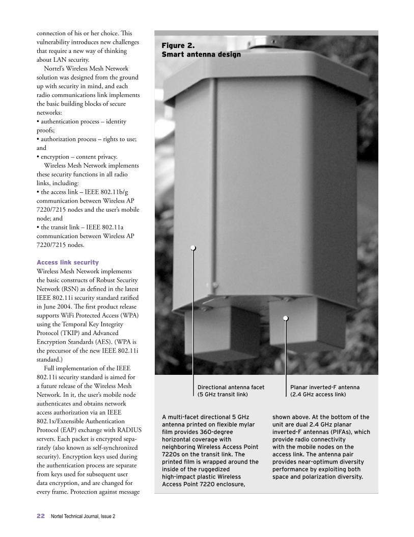
connection of his or her choice. This vulnerability introduces new challenges that require a new way of thinking about LAN security.
Nortel’s Wireless Mesh Network solution was designed from the ground up with security in mind, and each radio communications link implements the basic building blocks of secure networks:• authentication process – identity proofs;• authorization process – rights to use; and• encryption – content privacy.
Wireless Mesh Network implements these security functions in all radio links, including: • the access link – IEEE 802.11b/g communication between Wireless AP 7220/7215 nodes and the user’s mobile node; and• the transit link – IEEE 802.11a communication between Wireless AP 7220/7215 nodes.
Access link security Wireless Mesh Network implements the basic constructs of Robust Security Network (RSN) as defined in the latest IEEE 802.11i security standard ratified in June 2004. The first product release supports WiFi Protected Access (WPA) using the Temporal Key Integrity Protocol (TKIP) and Advanced Encryption Standards (AES). (WPA is the precursor of the new IEEE 802.11i standard.)
Full implementation of the IEEE 802.11i security standard is aimed for a future release of the Wireless Mesh Network. In it, the user’s mobile node authenticates and obtains network access authorization via an IEEE 802.1x/Extensible Authentication Protocol (EAP) exchange with RADIUS servers. Each packet is encrypted sepa-rately (also known as self-synchronized security). Encryption keys used during the authentication process are separate from keys used for subsequent user data encryption, and are changed for every frame. Protection against message
22 Nortel Technical Journal, Issue 2
Figure 2. Smart antenna design
Directional antenna facet (5 GHz transit link)
Planar inverted-F antenna (2.4 GHz access link)
A multi-facet directional 5 GHz antenna printed on flexible mylar film provides 360-degree horizontal coverage with neighboring Wireless Access Point 7220s on the transit link. The printed film is wrapped around the inside of the ruggedized high-impact plastic Wireless Access Point 7220 enclosure,
shown above. At the bottom of the unit are dual 2.4 GHz planar inverted-F antennas (PIFAs), which provide radio connectivity with the mobile nodes on the access link. The antenna pair provides near-optimum diversity performance by exploiting both space and polarization diversity.

Nortel Technical Journal, Issue 23
tampering is enabled by computing an 8-byte check value called Message Integrity Code (also known as Michael). The user’s mobile node is re-authenti-cated every time it re-associates with a new Wireless Access Point 7220/7215 node.
Transit link securityWhen a new Wireless AP 7220/7215 is powered on, it goes through the process of equipment authentication and authorization via an IEEE 802.1x/EAP protocol exchange with the RADIUS server. Successful node authentication and authorization grants an IP address for mesh network connectivity. An encryption scheme with dynamic key refresh is used for transit link control traffic between neighboring Wireless AP 7220/7215 nodes. Each Wireless AP 7220/7215 then establishes a secure IP Security (IPsec) tunnel with the Wireless Gateway 7250. [IPsec is a set of protocols developed by the Internet Engineering Task Force (IETF) to sup-port the secure exchange of packets at the IP layer.] All network management and user data traffic is carried within this IPsec tunnel and is protected using a 3DES encryption algorithm.
Smart antenna technologyThe smart antenna (antenna array) technology in Wireless Mesh Network builds on Nortel’s many years of leadership in this area. Like other technologies in Wireless Mesh Network, smart antenna technology is designed to simplify installation and operations for service providers (Figure 2). To deliver these capabilities, each Wireless AP 7220/7215 comprises: • a multi-facet directional 5 GHz an-tenna array, which requires no antenna alignment by installers, and provides 360-degree horizontal coverage on the transit link to neighboring Wireless AP 7220/7215s nodes to support ad hoc packet radio networking; and • dual 2.4 GHz planar inverted-F antennas (PIFAs) operating per IEEE 802.11b/g standards, which provide
a low-profile solution that delivers omnidirectional radio connectivity with the mobile nodes on the access link. The antenna pair provides near optimum diversity performance by exploiting both space and polarization diversity. Replacing the PIFA antennas with higher gain co-linear antennas also exists as a product option.
Incorporating this combination of complementary technologies – node auto-discovery, ad hoc networking and self-healing, access network security, and smart antenna arrays – Nortel’s Wireless Mesh Network solution helps overcome many of today’s wireless deployment challenges and enables new deployment models that can greatly reduce installa-tion time, lower capital and operating costs, and significantly expand WLAN coverage areas.
Stéphane Roch is System Architect, Wireless Mesh Network.
Acknowledgements: Nortel researchers Jerry Chow, Bill Gage, Simon Gale, and Pat Lawless.

New enabling technologies: Building blocks for next-generation wireless solutionsby Andy Jeffries, Morris Repeta, Wen Tong, David Wessel, and Peiying Zhu
Evolving today’s installed base of wireless access networks into tomorrow’s affordable broadband multimedia mobility platforms will require new ways to use the available — and scarce — spectrum more efficiently, and will hinge on innovative solutions across all points in the radio network. For the past several years, Nortel’s Wireless Technology Lab has been developing the fundamental technology building blocks that will provide increased spectral efficiency, greater throughput, higher speeds, and lower costs, today and into the future.
Increasing demand for broadband wire-less packet data access presents a funda-mental technology challenge: an increas-ingly crowded, and already scarce, radio spectrum means that little new space in the spectrum is available for emerging wireless high-speed data services.
Addressing this challenge requires the development of technologies and solutions that use the available spec-trum more efficiently than ever before, in order to achieve higher packet data throughput over the wireless link, sup-port a greater number of users within individual cells, and deliver a signifi-cantly enhanced experience to users. In addition, technologies that are more spectrally efficient will bring an order of magnitude reduction in the cost of transporting megabit-rate traffic, lead-ing to lower wireless infrastructure costs and more affordable broadband access.
In Nortel’s Wireless Technology Lab (WTL), researchers and engineers have been tackling these issues on a number of fronts – from air interface design, to advanced antenna technologies, to new radio frequency (RF) and hardware so-lutions. As a result, the team has synthe-sized, developed, and exploited a new set of enabling technologies that form the key building blocks for next-genera-tion wireless broadband access solutions.
Air interface designThe WTL recognized several years ago that using multiple transmit and receive antennas to create multiple parallel data streams would significantly increase user throughput and network capacity compared to current third-generation macro-cellular networks.
In fact, Nortel was one of the first vendors to recognize the powerful spec-tral efficiency and throughput gains that could be realized by combining ad-vanced multiple-input multiple-output (MIMO) antenna technology for data transmission with a signaling technique called orthogonal frequency division multiplexing (OFDM).
Since it began work on OFDM-MIMO six years ago, Nortel has invested nearly 100 person-years in researching, prototyping, and trialing OFDM-MIMO technology and has led the industry. To date, the company has made significant technical contri-butions to the key standards bodies, including the Institute of Electrical and Electronics Engineers (IEEE) and the Third Generation Partnership Project (3GPP), as well as tallied up an impres-sive list of industry firsts (see page 28).
Advanced antenna technologiesBuilding on its leadership in OFDM-
MIMO, along with its expertise in antenna design and extensive knowledge of propagation environments, the WTL is designing advanced MIMO-based antenna systems and techniques that offer dramatic capacity and coverage improvements while maintaining rea-sonable levels of complexity both at the base station and in the user equipment.
To this end, the WTL has designed a new compact base station antenna that can maintain a two-fold MIMO per-formance gain in both urban and rural propagation environments.
This new design, which is currently being developed and exploited in part-nership with a third-party antenna manufacturer, uses dual polarization an-tennas for transmission and reception. At the base station, pairs of antenna elements are oriented at +/-45°, result-ing in two-branch MIMO. In the case where four or more MIMO branches are required, two such antennas are sep-arated spatially. This antenna arrange-ment is attractive in that many base stations already use such a combination of polarization-diverse and space-diverse antennas to protect against fading.
In addition, the WTL has enabled this base station antenna to effectively combine MIMO with beamforming to further increase the number of users each antenna can support. The beam-forming techniques are enabled by an array of closely spaced elements, each of which is dual-polar, allowing for two-branch MIMO.
Fixed/switched MIMO beamform-ing: In current cellular wireless systems, most base stations already use multiple antenna elements to form a fixed beam
24 Nortel Technical Journal, Issue 2

Nortel Technical Journal, Issue 2 25
shape, generally very narrow in eleva-tion, in order to focus all of the trans-mitted energy slightly downward so that it is directed toward the users within the wide azimuth of the cell sector. With fixed/switched beamforming, a number of columns of antenna elements form multiple fixed narrow beams in azi-muth, further dividing the sector. The columns are closely spaced such that the signals arriving at each column are highly correlated.
The WTL has developed a proprie-tary fixed beamforming design, whereby three narrow beams are created within a conventional sector using a six-column antenna array (Figure 1a). This system uses a wider antenna but requires no change to the user equipment and pro-vides up to a three-fold increase in cell capacity over conventional tri-cellular systems. This approach is universally applicable to all access technologies and has already been very successfully trialed by Nortel in its CDMA (code division multiple access) systems.
Adaptive MIMO beamforming: The next step in complexity and perfor-mance is adaptive beamforming. In this case, each column of antenna elements must be controlled separately, allowing the beamshapes to adapt to the exact position and environment of the us-ers. Multiple users can share the same resource (channel), which may be codes in a CDMA system or subcarriers in an OFDM system, differentiated only by their ‘spatial signature’ – that is, the differences in phases of the signals that arrive at the elements of the antenna having traveled by different multi-path routes through the environment.
This adaptive beamforming tech-nique is referred to as spatial division multiple access (SDMA). Nortel has developed sophisticated algorithms that steer a beam toward the target user (Figure 1b). The algorithms may also steer nulls in the antenna pattern to-ward interfering users, maximizing the carrier-to-interference ratio. Although adaptive beamforming techniques are well known for enhancement of the
uplink, the WTL is now successfully developing them for use in the more challenging downlink, where we expect to provide further increases to system capacity and coverage over what is achievable with fixed multibeam techniques.
These two beamforming techniques – fixed and adaptive – can offer up to a seven-fold cell capacity improvement in the downlink as compared to a con-ventional antenna system. They are also fully complementary with a MIMO system. In fact, Nortel has shown that OFDM-MIMO with beamforming can provide 30 to 40 times higher capac-
ity on the downlink than current 3G deployments – and at one-tenth the cost (in a typical macro-cell site deployment, with two transmit and four receive antennas, and a three-beam-per-sector multibeam configuration).
MIMO antennas for the user de-vice: In addition to designing new base station antenna technology, WTL scien-tists also set out to ensure that the end-to-end antenna system would function optimally in a real-world environment. This meant making sure that multiple antennas could be deployed on the user equipment, an especially challenging re-quirement with severe space constraints.
Figure 1. Examples of techniques combining MIMO and beamforming
Nortel has designed a new base station antenna that effectively combines MIMO with beamforming to further increase the number of users each antenna can support. Beamforming techniques are enabled by an array of closely spaced elements, each of which is dual-polar, allowing for two-branch MIMO. This figure highlights two beamforming techniques — fixed and adaptive — which can offer up to a seven-fold downlink cell capacity improvement as compared to a conventional antenna system. They are also fully complementary with a MIMO system.
Figure 1a shows Nortel’s fixed beamforming design, whereby three narrow beams are created within a conventional sector using a six-column antenna array. This system provides up to a three-fold increase in cell capacity over conventional tri-cellular systems. Figure 1b depicts adaptive beamforming, where each column of antenna elements must be controlled separately, allowing the beamshapes to adapt to the exact position and environment of the users, and to steer nulls in the antenna pattern toward interfering users, maximizing the carrier-to-interference ratio.
Base station antenna supporting beamforming using closely spaced columns of elementsand MIMO using polarization diversity
Target
Figure 1a. Fixed
Target
Figure 1b. Adaptive
Interferer

26 Nortel Technical Journal, Issue 2
OFDM-MIMO: Key to greater performance
Early on, Nortel’s Wireless Technology Lab (WTL) recognized that combining multiple-input multiple-output (MIMO) antenna processing technology with orthogonal frequency division multi-plexing (OFDM) signaling would lead to significant boosts in capacity
and spectral efficiency. MIMO is a radio air interface technol-
ogy that can carry up to five times more data traffic than today’s UMTS HSDPA-ready networks. (HSDPA stands for High Speed Downlink Packet Access; see page 13.) MIMO works by creating multiple
parallel data streams between the multiple transmit and receive antennas, and by exploiting the multi-path phenomenon to differentiate among the multiple parallel signal paths between MIMO antennas. In this way, MIMO technology achieves a multi-fold user throughput gain and mul-
Co
din
g
Mo
du
lati
on
PH
Y/M
AC
in
terf
ace
MIMO MAC Layer 2
Beamformingprocess
MIMOpilots
Antenna
Subcarrier
MIMOmid-amble
Subcarrier
MIMO switching function
MIMO switching function
Key OFDMA-MIMO functions in IEEE 802.16e
This diagram highlights the key functional processes involved in transmitting packets in a system based on multiple-input multiple-output (MIMO) antenna processing and orthogonal frequency division multiple access (OFDMA) modulation. For transmission, packets first enter a coding modulation process, where they are encoded based on feedback from the channel quality indication (CQI) channel. The packets then travel through a MIMO sub-channelization process where they are mapped to the specific subchannels used with OFDMA, and are then sent to a MIMO coding scheme function where they are further mapped to specific subcarriers within each subchannel.
Each packet is then routed, through a MIMO encoding function, to individual subcarriers and mapped onto one or several antennas. If the system is configured with a beamforming function, the packets travel through a beamforming process, which applies a weighting to each packet. Finally, the packets are then transmitted to the antenna using IFFT (inverse fast fourier transform) transmission, guided by MIMO pilots that interact with the MIMO receiver. On the receiving end, if any transmission errors should occur, the system requests a packet retransmission via the MIMO HARQ (hybrid automatic repeat request) function.
MIMO sub-channel
IFFTIFFT
IFFT
Channel quality indication (CQI) channel
MIMO HARQ
MIMO coding scheme

Nortel Technical Journal, Issue 2 27
tiple aggregated network capacity increase compared to the current third-generation (3G) macro-cellular networks.
The basic proposition of MIMO technol-ogy is that the throughput will increase M-fold for the configuration of M transmit antennas and N receive antennas (in general N>M) compared to conventional single-input single-output (SISO) trans-mission with the same total transmit power and same bandwidth.
To handle the diverse deployment scenarios inherent in a radio environ-ment, several MIMO modes are typically employed and adaptively used based on real-time radio propagation conditions and quality of service (QoS) requirements. For instance: • transmit diversity mode, typically space time transmit diversity (STTD), is used to improve channel quality by increasing the robustness of transmission and reducing the packet error rate; and • spatial multiplexing mode, which creates several parallel independent transmission streams, is used to increase throughput.
OFDM is a scalable modulation tech-nique that uses many subcarriers, or tones, to carry a signal. OFDM signaling consists of a large set of spaced subcar-riers (with no mutual interference) to perform parallel data transmission in the frequency domain.
The major merit of OFDM is that it eliminates the multi-path channel-induced self-interference that occurs with high-speed data transmission over the wireless channel and which can limit transmission speed and spectrum efficiency. Moreover, unlike the GSM and CDMA air interfaces, OFDM eliminates self-interference without requiring equalization at the receiver, thereby dramatically reducing complex-ity without performance loss. As well, OFDM allows the coding modulation to be adapted to match the radio channel quality in both time and frequency, thereby achieving optimal transmission.
OFDM’s self-interference-free property
is ideally suited for MIMO transmission. The orthogonality among the subcarriers ensures that the MIMO transmission for-mat is preserved at each subcarrier at the receiver without any cross-interference, making the MIMO signal reception a sim-ple extension of basic OFDM signals. In addition, the OFDM signal allows the use of frequency domain orthogonal pilots to facilitate the MIMO channel estimation at the receiver. The accompanying diagram highlights the key OFDM-MIMO functions (as applied to the IEEE802.16e standard).
When used in combination, OFDM and MIMO offer the best solution for making more efficient use of the spectrum and boosting throughput, which also leads to significantly reduced operating costs and a better end-user experience.
Combining OFDM and MIMO required the WTL to develop several innovative capabilities to exploit the space-time and frequency diversity of OFDM-MIMO sub-channelization. These innovations include: • multi-user diversity based on fast packet scheduling and fast adaptive coding and modulation at the base station; • hybrid automatic repeat request (HARQ), to reduce the residual packet error in the physical layer, making the radio link TCP/IP-friendly and therefore increasing IP packet throughput; • adaptive MIMO transmission; • space-time coding-based MIMO HARQ; • a fast maximum-likelihood MIMO re-ceiver;• macro-diversity-based MIMO; • MISO (multiple-input single-output) with single antenna reception; and• sub-MIMO switching at both base station and user terminal sides.
Nortel leading the industry Over the past six years, Nortel has made ever-increasing strides in developing this fundamental technology and has led the industry both in technology-related pat-ents and in demonstrating OFDM-MIMO’s powerful capabilities (see Table, page 28).
For example, Nortel was the first to demonstrate live video streaming and file downloads using OFDM-MIMO, achieving data transmission speeds 25 times faster than today’s com-mercially deployed UMTS networks and five times faster than HSDPA. In this demonstration, a mobile user was able to view two live streaming videos simultaneously while downloading a 128 megabyte file at 37 megabits per second (Mbit/s) over a standard 5 MHz PCS band. This download was accom-plished in approximately 30 seconds compared to the approximately one hour that would be required on today’s UMTS networks with a 384 kbit/s channel.
Moreover, Nortel continues to make key technical contributions to the developing next-generation wire-less standards. For instance, Nortel’s innovative OFDM-MIMO capabilities have been pivotal to the development of IEEE 802.16e, the standard upon which emerging WiMAX (Worldwide Interoperability for Microwave Access networks) are based (page 31).

28 Nortel Technical Journal, Issue 2
To this end, the WTL has developed reference designs for incorporating four planar inverted-F antennas (PIFAs) into both a PDA device and laptop (Figure 2). De-correlation between these anten-nas was achieved through a combina-tion of polarization, spatial, and pattern diversity. Nortel has field trialed these designs outdoors and indoors in both urban and suburban environments and, in all cases, the MIMO paths to all four elements exhibited characteristics close to the theoretically optimal, completely de-correlated MIMO paths. These trials proved that the impressive MIMO per-formance gains predicted by theory can be realized in actual environments with practical antenna arrangements at the user equipment.
Metamaterial antennas: Nortel’s WTL is also conducting research into exciting new antenna technologies based on metamaterials – man-made materials with unusual electromagnetic properties (negative permittivity and permeabil-ity) that can be potentially exploited to make highly compact antenna elements. Such antennas would further address the challenge of placing multiple anten-nas into the limited available space on laptops and PDAs. Nortel research into these elements is continuing in 2005, with the aim of proving this technology through an initial prototype MIMO configuration suitable for use with a laptop. (Metamaterials also have inter-esting potential for RF components, as discussed later in this article.)
Advanced RF and hardware technologies In addition to advanced antenna tech-nologies, Nortel is developing solu-tions to minimize the amount of RF components and hardware required in a MIMO system. Because MIMO archi-tectures employ multiple transmit and receive radio chains, using conventional RF front-end hardware would require additional equipment, significantly increasing costs as well as space require-ments. Nortel is addressing these cost and size challenges with several innova-tions, including cell-site cable reduc-tion, advanced linear power amplifiers and transceivers, direct conversion tech-nology, metamaterials, and RF MEMS technology.
Cell-site cable reduction: The WTL is developing a technology that enables diversity-receive functionality to be combined onto the main cable at the cell site, along with main-receive and transmit signals. The associated RF module will be compatible with cur-rent cell site architectures and enable one cable per sector. This module will also be designed to evolve to MIMO and adaptive beamforming capabilities, enabling future MIMO systems to be deployed with two cables per sector. In addition, Nortel has developed a system architecture that uses simple, reliable, low-power electronics at the masthead in conjunction with a redesigned du-plexer at the base station.
Linear power amplifier and trans-ceiver technologies: In an OFDM-MIMO application, traditional analog transmit chains with linearized analog power amplifiers generally result in low flexibility and high operational expense. Technologies under development by the WTL aim to shift transceiver architec-tures to a fully digital transmit chain, offering the potential for frequency-agile and standards-agnostic transceiver architectures. As well, multiplexed transceivers for multi-antenna-based systems such as MIMO, together with integrated antenna and transceiver sys-tems that are fully remote-mountable
Nortel’s OFDM-MIMO technology leadership
2001: First nomadic MIMO demonstration system with peak rate of 10 Mbit/s in 5 MHz
2002: OFDM-MIMO demonstrated at 18.4 Mbit/s in 5 MHz with UMTS radio channel conditions
2003: OFDM-MIMO downlink integrated with W-CDMA uplink for testing over the air
2004: Mobile performance demonstrated with peak rate of 37 Mbit/s in 5 MHz
Figure 2. Example of MIMO antennas for a user device
To ensure that multiple antennas could be deployed on user equipment in an end-to-end MIMO-based system, Nortel has developed reference designs for incorporating four planar inverted-F antennas (PIFAs) into the user device, such as a laptop
(shown here) or PDA device. Nortel has field trialed these designs outdoors and indoors in both urban and suburban environments and, in all cases, these trials demonstrated the impressive MIMO performance gains.
Dual-polar base station antenna supporting two-branch MIMO
4 antenna elementslocated in corners of laptop screen section
Propagationchannel

Nortel Technical Journal, Issue 2 29
Figure 3. RF MEMS tunable front-end
Antenna
RFsignal
Systemclock
Bas
eban
d
RF receive chain
Frequency-tunable clock
LNA
Zero-IFdown converter
ADC
ADC
Local oscillator
Phaselockedloop/synthesizer
Phaselockedloop
MEMSTLPF
MEMSTLPF
MEMStunableRF filter
MEMSVCXO
MEMSVCO
Nortel is pioneering the development of radios that can be tuned to a wide continuum of different frequencies using simple software commands, enabling a single radio front-end (that is, the elements of the radio that are closest to the antenna) to easily tune to different country- and region-specific frequencies. This single radio package will reduce the costs traditionally associated with having to deploy a separate radio for each individual frequency. This diagram shows a frequency-tunable radio frequency (RF) receive chain that uses Nortel-developed RF micro-electromechanical systems (MEMS) technology to bring tunability to several key front-end elements. Each element can be tuned to different frequencies using a software-controlled external signal. Specifically, as the RF signal travels from the antenna into the radio front-end, it is first amplified by
the low-noise amplifier (LNA) and then enters a MEMS tunable RF filter that blocks out-of-band interferers. The RF signal is then down-converted to baseband and filtered using a low-power, high-dynamic-range RF MEMS tunable low-pass filter (TLPF), which serves to lessen the performance requirements on the analog-to-digital converter (ADC). The signal then enters into the digital signal processing domain. Nortel is also developing a frequency-tunable clock, which contains a MEMS beam resonator, called the MEMS voltage-controlled crystal oscillator (VCXO), that replaces a standard VCXO, and is used to provide a low-phase noise reference for the system. The frequency-tunable clock also contains a tunable MEMS voltage-controlled oscillator (VCO), used to generate a wide tuning range local oscillator with a frequency range from 300 MHz to 3 GHz.

30 Nortel Technical Journal, Issue 2
with simple high-speed serial interfaces, will offer greater deployment flexibility for operators.
Direct conversion technology: Nortel’s WTL has also designed a direct conversion demodulator, which is cur-rently being used in Nortel’s base station products. Direct conversion architec-tures provide a cost-reduction opportu-nity by reducing the parts count as well as the size of the board area. Currently, a higher-linearity component is being developed for OFDM-MIMO that could use a 64 quadrature amplitude modulation (QAM) scheme. The WTL has developed an integrated zero-IF (in-termediate frequency) quad-receive chip to prove the concept for the four-branch receiver radios in the user device.
Metamaterial technology: Nortel is also working, in conjunction with a leading university, to exploit the proper-ties of metamaterials (described earlier) for use in high-directivity couplers. The aim is to have a manufacturable solu-tion before the end of 2005. Other areas under investigation by Nortel where this technology could have an impact include power amplifiers and duplexers/multiplexers.
RF MEMS tunable technologies: RF micro-electromechanical systems (MEMS) technology is being used by the WTL, along with direct conversion topologies, to develop a radio front-end that is tunable to different frequencies. This enabling technology would provide significant cost-reduction opportuni-ties, since the same radio module could be used for various cellular standards, such as 3G evolution and WiMAX. Furthermore, these tunable front-ends would be the key enabler to cognitive radios, a next-generation radio ac-cess technology. Currently, several RF building blocks – including high-qual-ity resonators, tunable inductors, and capacitors – are being developed by the WTL (Figure 3).
The WTL is also developing min-iature band reject filters (MBRFs) – another type of RF MEMS device. MBRFs can be implemented as surface
acoustic wave (SAW) devices or film bulk acoustic resonators (FBARs), and will be used to replace large and ex-pensive cavity filters at one-tenth the cost and with a footprint that is several orders of magnitude smaller. A combi-nation of MBRFs can be used to syn-thesize various frequency responses and provide solutions over many frequency bands of interest.
Next steps In addition to RF hardware and ad-vanced antenna technologies for next-generation OFDM-MIMO systems, Nortel is exploring new ways to provide ever greater coverage and throughput. For instance, OFDM-MIMO, while currently being developed as a link-layer technology, could bring new benefits and performance improvements as it is pushed deeper into the network. OFDM-MIMO as a network layer, for example, would enable such new capa-bilities as collaborative communication among devices. In this area, the WTL is working closely with several leading universities around the world, including Harvard University in the U.S.
The WTL is also working to de-velop multi-hop architectures, whereby transmission to individual devices can be extended across a greater distance via several relays, essentially allowing a device that may not be directly con-nected through a MIMO link to “hop” through multiple other devices to reach one that does have a direct connection.
In addition, the WTL is tackling a new radio access technology – cognitive radio. These future radios will set a new paradigm for spectrum and tunability, by incorporating machine-learning capabilities that enable the radios to “think” and make decisions, such as which frequency to use.
Through such initiatives, Nortel’s WTL is working far ahead of the de-mand curve to develop the next tech-nology enablers that will address the requirements of future networks and services. In the process, Nortel will con-tinue to play a significant technology
leadership role, defining the evolution path for broadband wireless access and proving-in the feasibility of new en-abling technologies.
Andy Jeffries is Senior Manager, Spatial Processing Technology, Wireless Technology Lab.Morris Repeta is Senior Manager, Radio Technology, Wireless Technology Lab.Wen Tong is Senior Manager, Advanced Wireless Access Systems, Wireless Technology Lab.David Wessel is Senior Advisor, Radio Architectures, Wireless Technology Lab.Peiying Zhu is Senior Manager, Broadband Wireless Technology, Wireless Technology Lab.

Nortel Technical Journal, Issue 2 31
WiMAX: Untethering the Internet userby Bill Gage, Charlie Martin, Ed Sich, and Wen Tong
Worldwide Interoperability for Microwave Access, or WiMAX, has the potential to provide a significant improvement in cost and performance compared to existing wireless broadband access systems. Nortel, in addition to playing a lead role in standards development and actively participating in the industry’s WiMAX Forum, is drawing on its decades of wireless technology leadership to design a WiMAX solution that will provide highly differentiated levels of performance across the entire network.
Within the past 18 months, Worldwide Interoperability for Microwave Access, or WiMAX – a technology that offers wireless users higher bandwidth and more capacity over greater distances – has seen a meteoric rise in global interest, across every geographic region and among all industry players.
Aimed at metropolitan area networks (MANs), WiMAX is an emerging wireless broadband access technology that will deliver broadband multimedia data ubiquitously over wireless links at several times the speed of traditional circuit-switched wireless systems, and over a far greater coverage area than today’s proprietary wireless local area network (WLAN) access solutions, such as 802.11 (WiFi) technology.
Where WiFi enables affordable broadband Internet access within short-range “hot spots,” at distances measured in tens of meters, WiMAX is designed to deliver the same access, at similar costs, but across tens of kilometers – and ultimately, with greater performance and higher speeds (Figure 1). In short, where WiFi provides high bandwidth but not distance, and current cellular systems provide distance but not high bandwidth, WiMAX will provide both.
WiMAX will give users uninterrupted, untethered access to a rich variety of high-bandwidth services – such as networked
gaming, streamed digital music, TV and other entertainment services, videoconferencing, video surveillance, and real-time dissemination of a variety of information – not only around homes, offices, coffee shops, and even schools, but also as users roam in rural, suburban, and metropolitan areas.
What’s more, with WiMAX, users will no longer perceive wireless Internet access as being inferior in quality compared with today’s fixed DSL (digital subscriber line) and cable access offers. Instead, WiMAX is expected to bring long-sought-after performance parity between wireless and wired Internet access.
These capabilities are possible because the standard upon which WiMAX technology is based – IEEE 802.16 – is being designed from the ground up to be truly broadband and packet-based. A non-line-of-sight technology, IEEE 802.16e (the ‘e’ refers to the fully mobile version of the standard) is based on orthogonal frequency division multiplexing (OFDM) and OFDM with multiple access (OFDMA), a new air interface that brings significantly improved levels of spectral efficiency, data throughput, and capacity compared to previous generations of radio technologies. Moreover, when combined with multiple-input multiple-output (MIMO) antenna processing
technology, the resulting OFDM-MIMO combination – a Nortel technology stronghold – can boost capacity and performance even further (see page 26).
In fact, WiMAX represents a potentially significant disruptive technology that challenges the way wireless networks have traditionally been designed, as well as where certain functions will be placed within those networks. Nortel is addressing these challenges and, in the process, driving several innovations that will bring added levels of performance and cost efficiency to real-world solutions.
Addressing the technology challengesThe challenges in designing end-to-end WiMAX networks lie primarily with the need to handle the bursty, unpredictable nature of IP-based traffic over a radio link, enable any-to-any connectivity and mobility, and achieve cost models similar to or better than today’s WLAN offerings.
Specifically, Nortel is working to:• minimize latency and network delay for the considerably higher bandwidths and volumes of packet data; • provide adaptation to various spectrum policies around the globe; • ensure seamless mobility across base station boundaries; and• reduce the number of radio frequency (RF) cables that the antennas must support.
Minimizing latency and network delay: Unlike circuit-switched wireless systems, where traffic is typically predictable and resource allocation and scheduling decisions need to be made only when the call is initialized, WiMAX networks must be designed

to handle the very bursty and unpredictable nature of packet-based traffic (IP or Ethernet). Critically important to this goal is the ability of the network to minimize delay by allowing system-level decision-making to be done very quickly – often on a frame-by-frame basis. Otherwise, such multimedia traffic as real-time video and Internet downloads would be subject to intolerable delays or interruptions.
To enable this rapid-fire decision-making, the control of resource
allocation and scheduling – which up until now has typically resided in a centralized higher-level network entity, such as the base station controller (BSC) or radio network controller (RNC), and optimized resources across the entire network – must reside further down in the network hierarchy, in the individual base stations.
Scheduling services are defined in IEEE 802.16 for handling the usual packet data traffic classes – constant bit rate, real-time variable rate, non-real-time variable rate, and best effort
– while the specific requirements of a particular traffic flow (e.g., committed rate, peak rate, maximum latency) are embodied in the connections that are established between a mobile station (MS) and a base station (BS) to carry that traffic.
Radio resources in an OFDMA system are allocated to mobile stations in both time and frequency. The 802.16 Media Access Control (MAC) layer (Layer 2) is designed to handle bursty packet data traffic by allocating those radio resources dynamically among mobile stations according to current traffic demands and radio-link conditions.
This manner of scheduling, along with advanced coding and automatic repeat request processing, dictates that all of the time-critical functions of the 802.16 MAC layer reside in the BS. The location of other functions in the wireless access network is dictated by the requirements of the application that uses the 802.16 technology. These applications include:• Fixed access – In a fixed access application (e.g., using broadband wireless as a DSL loop extension off a DSL access multiplexer, or DSLAM), each BS can be considered a standalone entity. Therefore, all wireless access network functions can be embodied in each BS.• Mobile access – In a mobile access application (e.g., using broadband wireless as a form of wide area WiFi), mobile stations can move between BSs while maintaining service continuity. In this application, session and mobility management (SMM) is introduced into a separate network entity – the mobile control point (MCP) – to redirect traffic to the BS currently serving an MS and to manage the handover between base stations.
Supporting this MAC functionality in the base stations, however, raises new challenges in how best – and where – to support other critical functions, such as macro diversity and mobility. In fact, Nortel recognized early on
32 Nortel Technical Journal, Issue 2
Figure 1. Performance comparison of WiFi and WiMAX, with and without MIMO
WiMAX systems operating in licensed bands offer significantly wider coverage and greater network throughput than today’s WiFi shorter-range “hot spot” coverage. Th ese improvements are possible because WiMAX is designed as a high-transmit-power and point-to-multipoint macro-cellular system, and makes use of more advanced modulation and coding schemes, such as convolutional turbo coding, than does WiFi. MIMO systems and spatial processing technology can be applied to both WiFi and WiMAX systems to increase performance. For the 20-MHz bandwidth time division duplexing configuration, the grey line indicates the first
generation of WiFi technology, which provided some 20 Mbit/s throughput within a few tens of meters of the base station and could operate out to a distance of some 60 meters. The second generation of WiFi (black line), with two MIMO antennas at each end of the radio link, provides higher throughput and wider coverage. By contrast, WiMAX can quadruple throughput speeds, with significantly wider coverage, as indicated by the two purple lines. The light purple line shows the performance of WiMAX configured with a single antenna. The dark purple line shows the even greater performance possible when a pair of MIMO antennas is deployed at each end of the radio link.
Aggre
gat
ed s
yst
em t
hro
ughput
(Mbit
/s)
User distance from base station (meters)
100
10
20
50
40
30
60
70
80
90
100
100 1,000 10,000
WiMAX 802.16e (2x2 MIMO)
WiMAX 802.16e
WiFi 802.11n (2x2 MIMO)
WiFi 802.11a

Nortel Technical Journal, Issue 2 33
Figure 2. Nortel’s view of network architecture to enable WiMAX capabilities
Operator’s Intranet
Datagram distribution network
Internet
Border gateway (Firewall, NAT, etc.)
Mobile control point
Mobile control point
A broadband wireless access WiMAX-enabled network includes the following key elements: The base station provides connectivity over the radio link and manages radio link resources. It is responsible for physical layer functions (e.g., adaptive modulation and coding); radio resource management and schedul-ing; radio link retransmission (ARQ/HARQ); packet segmentation/reassembly; packing/unpacking; and traffic encryption and frame authentication.The mobile control point (MCP) provides the control and mobility anchor point for a mobile station (MS) as it moves between base stations (BSs) in the access network. The MCP is responsible for device and subscriber authentication; service authorization; security key management; accounting; handover and macro diversity coordination; downlink traffic replica-tion and distribution; and uplink traffic selection and forwarding. It is important to understand that unlike BSCs or RNCs in CDMA networks, the MCP in a WiMAX network does not contain base station control functions; these functions reside in the base stations themselves.Network operations and support services (NOSS) include functions required to operate and maintain the wireless access network. These include element
management; authentication, authorization, and accounting (AAA) services; and MS IP configuration services.A datagram distribution network provides full connec-tivity between all MCPs and all BSs in the access network. It may be a third-party network or may be built as an overlay on a third-party network. Its primary functions are traffic aggregation and distribution; the latter is implemented as a datagram delivery service, meaning that an IP (or Ethernet) datagram injected at an ingress point is delivered error-free to the egress point associated with the destination address in the datagram header. Since part of the distribution network may be a third-party network, all traffic between an MCP and BS is carried in a secured tunnel (such as IPsec ESP).The operator’s Intranet provides connectivity between MCPs and other elements of the operator’s network (including NOSS), as well as any subscriber services (not shown) that are hosted locally.A border gateway is a collection of functions that provide interworking between the operator’s network and the Internet. Typical functions include firewall, network address translation (NAT), and inter-domain routing.
Basestation
Basestation
Basestation
Network operations and support services
MS configuration services
Elementmanagement
AAAservices

34 Nortel Technical Journal, Issue 2
The IEEE 802.16 technology
Developed by the Institute of Electrical and Electronics Engineers Standards Association (IEEE-SA), the IEEE 802.16 standard specifies an air interface for the "first-mile/last-mile" connection in wireless metropolitan area networks (WMANs). This standard supports several different physical layers [including orthogonal frequency division multiplexing (OFDM) and OFDM with multiple access (OFDMA)] and focuses on point-to-multipoint operation in licensed and unlicensed bands from 2 GHz to 60 GHz.
The two latest major revisions of IEEE 802.16, which are focused on point-to-multipoint operation in licensed bands below 11 GHz, will support WiMAX product introductions over the next three to five years. These revisions are: • IEEE 802.16-2004 (formerly known as 802.16d), which specifies the physical (PHY) and Media Access Control (MAC) layers for fixed access and point-to-point backhaul applications; and• IEEE 802.16e, which is geared toward nomadic and mobile operations and higher capacity point-to-multipoint systems. This version also incorporates scalable OFDMA (S-OFDMA) PHY.
Technical characteristics of IEEE 802.16e are as follows:• nomadic and mobile operation with wide area coverage or fixed/hot spot applications;
Table 1. System capacity of WiMAX TDD (DL/UL ratio 2:1)
10 MHz TDD at 2.5 GHz (full queue FTP traffic) IEEE 802.16e OFDMA downlink capacity
MIMO antennas (transmit x receive) 1x1 1x2 2x2 2x4 4x2 4x4
Bits/sec/Hz/sector 1.2 1.8 2.8 4.4 3.7 5.1
Aggregate sector throughput (Mbit/s) 7.6 11.6 17.8 27.7 23.6 32.6
As the number of MIMO antennas configured in a WiMAX system increases, spectral efficiency improves significantly and network throughput/speed grows dramatically — more than quadrupling in the
case of a 4x4 MIMO antenna array. This Table shows this substantial improvement in a typical 10 MHz time division duplexing (TDD) macro-cell deployment at 2.5 GHz spectrum.
Adaptive coding and modulation
To ensure that users constantly receive the fastest data rate possible, 802.16e employs fast link adaptation and modulation/ coding techniques, which enable WiMAX systems to dynamically adapt the coding modulation — for instance, quaternary phase shift keying (QPSK) or quadrature amplitude modulation (QAM) — to accom-modate varying conditions that can often occur on the radio link
between the user and the base station. These conditions could include such impairments as interference from buildings or trees or fading of the signal as the user moves farther away from the base station. This diagram shows the OFDMA PHY (physical) coding modulation set operating at 20 MHz bandwidth, and the correspond-ing peak data rates.
Aggre
gat
ed s
yst
em t
hro
ughput
(Mbit
/s)
User distance from base station (meters)
64 QAM
16 QAM
QPSK
100
10
20
50
40
30
60
70
80
90
100
100 1,000 10,000
WiMAX 802.16e (2x2 MIMO)

that these functions would need to be incorporated into WiMAX systems, and has made key contributions to the 802.16 standards in these areas. These contributions include:• Basic macro diversity, which is supported through fast base station switching (FBSS) for both uplink and downlink traffic. In this mode of operation, traffic for a mobile station may be sent through one of the BSs in the diversity set of the MS. The base station is dynamically selected by the MS based on current radio link conditions, enabling fast handovers due to fading conditions.• Macro-diversity handoff (MDHO), which allows downlink traffic to a mobile station to be transmitted from all base stations in the diversity set simultaneously. The MS then reconstructs the downlink frame either through RF energy combining or through soft data combining. In the uplink direction, each transmission from the mobile station may be received by multiple base stations in the mobile station’s diversity set; each base station then forwards any frames that are received error-free.
Although these macro diversity concepts exist in other systems, such as CDMA, to improve coverage at the cell edges, implementation of MDHO in an OFDMA system differs from that of soft handover in a CDMA system and is an area where Nortel has made key innovations. Also in contrast to CDMA systems, MDHO and FBSS are not static modes of operation. Instead, MDHO and FBSS are activated and deactivated on an as-required basis based on the radio-link conditions currently encountered by the MS. This state-driven approach conserves radio resources and increases overall system capacity.
Regardless of the network topology, the time-critical functions of the 802.16 MAC reside in the base station even for the FBSS and MDHO configurations. Figure 2 illustrates Nortel’s view of the broadband wireless
Nortel Technical Journal, Issue 2 35
• OFDMA in time division duplex (TDD) and frequency division duplex (FDD) operations;• scalable OFDM/OFDMA with carrier requirements from 1.25 MHz to 20 MHz bandwidth;• flexible frequency reuse pattern, including 1 and n (n>1);• fast link adaptation and modulation/coding;• high-efficiency coding and error correction schemes;• multiple dimension of diversity; and • MIMO (multiple-input multiple-output) technology (MIMO also exists in 802.16-2004, although with fewer enhancements).
Based on these technical characteristics, consequent maximum spectral efficiencies in an interference-limited environment are to be 6 and 2 [bps/Hz/cell (sector)] for downlink and uplink, respectively, and the spectral efficiencies at the cell edge are expected to be 2 and 1 [bps/Hz/cell (sector)] for downlink and uplink, respectively.
WiMAX systems, which are based on the IEEE 802.16 standard, will offer significant improvements over existing wireless metropolitan area network (WMAN) solutions. These improvements include greater spectral efficiency and
therefore throughput and speed (Table 1), as well as higher bandwidth and greater coverage, flexibility, and adaptability (Table 2 and Diagram).
Nortel is playing a leadership role in the development of 802.16 specifications, and has made more than 20 technical contributions, particularly in the area of OFDM-MIMO antenna technology (see page 26). At the same time as the IEEE 802.16 specifications continue their rapid standardization, the industry, through the WiMAX Forum, is moving aggressively to promote these standards and ensure product interoperability (see page 37). Nortel is also active on this front, as a principal member of the WiMAX Forum.
Table 2. IEEE 802.16d/e features
FFT size IEEE 802.16d IEEE 802.16e
128 N/A S-OFDMA Full Mobility
256 OFDM Fixed/Portable OFDM Portable/Nomadic
512 N/A S-OFDMA Full Mobility
1024 N/A S-OFDMA Full Mobility
2048 OFDMA Fixed/Portable S-OFDMA Full Mobility
The IEEE 802.16 standard is characterized by OFDM and scalable OFDMA (S-OFDMA) technologies with various FFT (fast fourier transform) sizes, which indicate the number of subcarriers in the OFDM signal.
S-OFDMA is a unique feature of WiMAX, and provides the agility to handle diverse spectrum allocations. This Table lists the application of the OFDMA physical (PHY) layer.

access network architecture that enables WiMAX capabilities.
Flexible spectrum allocation: In contrast to previous generations of wireless technologies, which are each tied to a specific bandwidth on the wireless spectrum, and in recognition that spectrum is a limited resource, WiMAX systems must be able to flexibly scale across a wide range of different channel bandwidths, to accommodate the diverse range of frequency carriers, band allocations, and radio-link conditions around the globe. These systems must also support combined fixed and mobile usage models.
IEEE 802.16e addresses this need for global-scale mobility with an advanced, scalable OFDMA physical (PHY) layer solution that, unlike many other OFDM-based systems, such as WLAN, supports variable channel allocations between 1.25 MHz and 20 MHz for non-line-of-sight (NLOS) operations, with fixed subcarrier spacing for both fixed and portable/mobile usage models. No other technology has this property.
The OFDMA PHY architecture is based on a scalable channelization structure with a variable number of subcarriers according to the channel bandwidth. This architecture includes the following key features:• subcarrier spacing that is independent of bandwidth;• number of subcarriers that scales with bandwidth; • the smallest unit of channel bandwidth allocation, specified based on the concept of subcarriers, is fixed and independent of spectrum allocation and other modes of operation; and• options such as FBSS and MDHO that trade improvements in individual mobile station performance for overall system capacity.
Seamless mobility: Ensuring seamless mobility is another challenge presented by WiMAX systems and must be considered from two perspectives: handover and security.
Handover: The challenge with handover in a WiMAX system lies in the fact that smooth handover requires a “make before break” sequence – that is, before a mobile device moves out of range of one base station, it begins communicating with a second base station before disconnecting from the first. Existing OFDM-based systems use the opposite “break before make” approach, in which the mobile device momentarily disconnects from the first base station before it starts communicating with the next. This “break before make” approach worked well for best-effort packet data services, such as web browsing, but for interactive multimedia traffic such as voice and video, it would result in delay, interruption, or disconnection and therefore an unacceptable user experience.
The “make before break” scheme relies on FBSS and MDHO, described
earlier. Spearheaded by Nortel, both are advanced OFDM mobility technology innovations that have been contributed to the IEEE 802.16e standard, in collaboration with other companies.
Security: In many wireless systems, strong security has been included as an afterthought. In 802.16e, security is an integral part of the standard, covering aspects of device and user authentication, privacy (through encryption), and validation (through message integrity checks). Modern cryptographic algorithms and techniques are supported by the standard, including the ability to dynamically refresh keys and to detect replay attacks.
The security sub-layer of 802.16e protects all of the MAC frame, requiring that encryption and integrity check operations be implemented in the base station. When FBSS and MDHO operations are enabled, the
36 Nortel Technical Journal, Issue 2
Figure 3. Cable reduction technology
Nortel is developing cable reduction technologies that allow multiple antenna signals to travel between the top and bottom of the tower along a single radio frequency (RF) cable. For a traditional cellular system, this technology enables a single RF cable to carry transmit, receive- main, receive-diversity, and control and synchronizing signals, as well as DC power, bringing cost
reductions and greater deployment flexibility. This signal combining (or multiplexing) technique can be done in the time, frequency, phase, or code domains. For a MIMO-based system, this technology innovation is key to enabling multiple transmit and receive signals to travel on a single RF cable, providing cost-effective connectivity between the base station and antenna.
An
ten
na
1
An
ten
na
2
Demultiplexer Base station
Mastheadmultiplexeror radio

Nortel Technical Journal, Issue 2 37
The WiMAX Forum
Nortel is a principal member of the WiMAX Forum, an organization of some 170 companies from across the industry that are working to promote compliance and interoperability of broadband wire-less products that adhere to the IEEE 802.16 standard.
The aim of these products is to de-liver faster and more affordable wireless data, voice, and video services, with broader coverage, for businesses and consumers.
Through the work of the WiMAX Forum’s testing and certification program, service providers will be able to buy equipment from more than one company and be confident that everything works together to achieve lower cost and faster growth for broadband wireless. Products certified by the WiMAX Forum will provide fixed, nomadic, portable, and, eventually, mobile wireless broadband connectivity without the need for line-of-sight with a base station.
In January 2005, the WiMAX Forum announced the formation of a Networking Working Group, function-ing under the umbrella of the Technical Working Group. This Working Group will undertake to develop and publish the specifications that will define the network architecture, interfaces, and protocols to enable nomadic, portable, and fully mobile operations. Nortel anticipates that Revision 1 of these specifications could be published by the end of 2005 to early 2006.
In a typical cell radius deployment of three to ten kilometers, it is expected that WiMAX technology will be incor-porated in indoor and outdoor desktop customer premises equipment in 2006, with notebook computers and PDA form factors to follow in 2007, which will allow urban areas and cities to become MetroZones for portable outdoor broad-band wireless access.
context of the security association between the mobile station and the network (encryption and integrity check keys, replay protection sequence numbers, etc.) is distributed across all base stations in a mobile station’s diversity set. Coordination of this context is a major challenge and is an area where Nortel has made key innovations in its network design.
Cable reduction: In addition to addressing mobility and latency issues, Nortel is working to reduce the number of RF cables used on antenna towers.
High-performance WiMAX systems will use OFDM-MIMO techniques, which will include multiple-element antenna arrays at the top of the radio tower. In a typical installation, each antenna element is connected via RF cables to a corresponding radio transceiver, located near the bottom of the tower for easy access and maintenance. These RF cables are
heavy and expensive, and in a MIMO system a large number of them may be required, which adds to system costs and requires the use of antenna towers capable of handling the extra cable weight.
One way to reduce the number of RF cables on a tower is through the use of cable reduction technology, as illustrated in Figure 3. Such a system combines multiple antenna signals to allow them to travel on a single RF cable between the top and bottom of the tower. This signal combining – or multiplexing – would usually be done in time, frequency, phase, or code domains. Such an approach slightly increases the complexity of the infrastructure at the top of the tower, and will require new techniques for maintenance access by operator staff. Technical challenges of this scheme include the need for high dynamic range, linear signal handling capability
in the receive signal path, and the ability to multiplex and demultiplex the high power levels inherent in the transmit signal path. Nortel recently demonstrated a high-performance cable reduction system for combining receiver signals, and is currently perfecting the technology to extend it to support the combining of high-power transmit signals.
As a next step, Nortel is developing technologies that eliminate RF cables altogether by relocating the complete radio subsystem to the top of the antenna tower, which allows the radio and antenna systems to be more closely connected. In this case, only power and digital signals flow between the radio and network interface subsystems, and these can travel on a single, low-cost cable. This relocation, in turn, saves tower and cabling costs, although it also introduces further complexities for the design and maintainability of the tower-mounted radio equipment.
To ensure the reliable operation of radio equipment at the top of the antenna tower, and of cable reduction schemes in general, Nortel is using several of its industry-leading advanced technologies to meet these requirements for future WiMAX systems, including: • high-efficiency electronics subsystems that dissipate only small amounts of heat and operate over wide temperature ranges; • miniature semiconductor filters and duplexers that save size and weight; and • specialized protection components that allow operation of the radio equipment in harsh outdoor environments where extreme temperatures, frequent lightning strikes, heavy precipitation, or high humidity might prevail.
Potential applications, target marketsThe widespread appeal of WiMAX systems lies in the fact that the technology can be applied to a host of different applications offered by a range of different providers – from traditional

wireless cellular operators through to wireline providers and new WiMAX entrants.
For instance, for the fixed wireless WiMAX version – IEEE 802.16-2004 – the primary value lies in the replacement of wired T1/E1 or DSL circuits for the “last mile” connection between end-user devices or premises and the high-speed transport network. Potential applications include:• wireless backhaul for WLAN hot-zone and hot-spot traffic;• broadband access for small to medium enterprises, as an alternative to frame relay or circuit services (T1/E1);• cell site (GSM, UMTS, CDMA BTS) backhaul, when used in conjunction with circuit emulation services; and• consumer broadband services in rural and other underserved markets, or where DSL and cable services are not available or cost-competitive.
With the introduction of WiMAX systems based on IEEE 802.16e, the increased capacity of OFDM-MIMO will enable higher-speed links for “last mile” connections. This increased capacity will also enable the introduction of new Ethernet-based data services for consumers and small to medium enterprises (e.g., transparent LAN services) and/or deployment of DSL-like services in higher-density suburban markets. In addition, IEEE 802.16e will enable a new set of high-speed nomadic and mobile data services, bringing a WiFi-like broadband experience to consumers over a wide metropolitan area.
As the promise of WiMAX unfolds to become a truly widespread consumer broadband service, Nortel will continue to focus on the technology innovation that will bring its customers lower-cost solutions and industry-beating performance and reliability.
Bill Gage is Director, Access Network Evolution, Wireless Technology Lab. Charlie Martin is Director, WiMAX Network and Systems Product Line Management.Ed Sich is Director, RF Technology, Wireless Technology Lab.Wen Tong is Senior Manager, Advanced Wireless Access Systems, Wireless Technology Lab.
38 Nortel Technical Journal, Issue 2

Nortel Technical Journal, Issue 2 39
In wireless access, a number of exciting technologies promise to have a signifi-cant impact on next-generation wireless access.
Among these evolutionary tech-nologies is High Speed OFDM Packet Access (HSOPA), which Nortel has proposed for the “Network Evolution” specified by the Third Generation Partnership Project (3GPP). 3GPP is an administrative consortium that produc-es technical specifications and a frame-work for third-generation GSM/UMTS wireless networks for a global group of standards organizations, including the European Telecommunications Standards Institute (ETSI), Association of Radio Industries and Businesses (ARIB), and others.
As envisioned by Nortel, HSOPA will combine multiple-input multiple-output (MIMO) – an advanced antenna and space-time processing technology – with orthogonal frequency division multiplexing (OFDM) – a robust and spectrally efficient base radio technol-ogy used by WiFi (IEEE 802.11) and WiMAX (IEEE 802.16). Combining
by Philippe Duplessis
High Speed OFDM Packet Access (HSOPA) is the next step in UMTS network evolution beyond the high-speed HSDPA/HSUPA technologies. HSOPA is a concept proposed by Nortel in the Third Generation Partnership Project (3GPP) that uses orthogonal frequency division multiplexing (OFDM) and multiple-input multiple-output (MIMO) antenna technology. The combination of these technologies will be key to achieving the much higher speeds needed to better support such bandwidth-hungry wireless applications as streaming video, mobile gaming, and large file transfers, as well as significantly decreasing the cost of data transfers. Nortel is taking a lead role in standards development for HSOPA, and once the HSOPA standard is approved (expected in 2007), Nortel will act quickly to make this technology available across its UMTS product portfolio.
MIMO with OFDM will enable wire-less systems to support more than twice as many subscribers as OFDM alone (see page 24).
By dramatically lowering the cost per megabit, HSOPA promises to make deployment of such high-band-width applications as streaming video, mobile gaming, and multimedia com-munications feasible for more and more users.
HSOPA is unique in that it is de-signed to provide a simple evolution path for UMTS service providers as they migrate from UMTS to High Speed Downlink Packet Access (HSDPA) to High Speed Uplink Packet Access (HSUPA) and then to HSOPA – with each step representing an increase in functionality, higher data speeds, and better spectral efficiency. (For more on HSDPA/HSUPA, see page 13).
Deployment of HSOPA will also provide users with choice: gold us-ers will be able to pay a premium for the top speeds, while others, likely the majority, will receive more moderate speeds, albeit at still higher rates than
those available today.Because neither OFDM nor MIMO
technologies have ever been used in a standard public cellular system, together they can be considered a disruption in technology. That disruption, which paves the way for higher spectrum ef-ficiency, is an absolute requirement to facilitate convergence of services and transparent access to existing residential and business applications, whether the user is fixed or mobile.
Nortel has a solid leadership position in both these technologies. Earlier this year, Nortel’s Wireless Technology Lab (WTL) in Ottawa built and successfully tested the world’s first demonstration system that was able to deliver 37 Mbit/s on the downlink in a 5 MHz channel, under lab conditions but taking into account noise and fading conditions found on real-world cellular networks. The test network showed that with OFDM-MIMO, wireless subscrib-ers can download a 128 megabyte file in approximately 30 seconds – four to ten times faster than today’s 3G wireless networks.
Nortel has also made significant technical contributions to key standards bodies.
Over a two-year period, from June 2002 to 2004, Nortel contributed more than 60 proposals to the 3GPP in sup-port of OFDM. Its OFDM-MIMO proposal was submitted at the 3GPP meeting held last April in Beijing, China, and discussions around the proposal are still in progress. (OFDM-MIMO technology is also being evalu-ated for CDMA network evolution beyond 1xEV-DO Revision A.)
HSOPA: Exploiting OFDM and MIMO to take UMTS beyond HSDPA/HSUPA

HSOPA objectivesThe 3GPP meeting held in Beijing of-fered a first opportunity to compare visions of different vendors and opera-tors on OFDM-MIMO technologies for wireless networks. Current views on downlink OFDM are reasonably close, but there are several different opinions on the uplink multiple access scheme, although most of the competing pro-posals are OFDM variants. There is, however, agreement on the performance objectives required to achieve the higher data rates demanded of next-generation wireless systems. The objectives include:• Increased spectral efficiency: The throughput per cell, for a 5 MHz chan-nel, is expected to reach 40 Mbit/s (compared with up to 2 Mbit/s for standard UMTS and up to 14 Mbit/s for HSDPA).• Support for higher bandwidths: The number of simultaneous users per cell on a 5 MHz carrier should be larger than 100.
• Lower cost per bit: Meeting the first two objectives will contribute to greatly reduced costs of data services delivery.• Improved quality of experience (QoE): The reduction in latency time, ex-pressed as the time for 32 bytes Ping, is expected to reach 20 ms (compared with 120 ms with standard UMTS).
Reaching these objectives will require significant changes in the architecture of the access network; these changes are currently in the early stages of discus-sion in standards bodies. The challenge here is to reduce the number of network nodes involved in data processing and transport, in order to improve latency time (the delay between sending a re-quest for data and receiving a response) to better support delay-sensitive, inter-active, and real-time communications.
To help achieve the HSOPA objec-tives, Nortel is continuing its advanced R&D in the two enabling technologies: • OFDM, which is easily scalable and intrinsically able to handle the most
common radio frequency (RF) distor-tions without the need for complex equalization techniques; and • MIMO, which improves spectral efficiency by exploiting the rich scat-tering of RF signals typical of indoor and urban environments, facilitating high-data-rate transmission in a scarce spectrum typically controlled by regula-tory bodies.
OFDM technologyOver the past several years, OFDM has been successfully used in a number of wireless and wireline applications and has generated considerable interest, particularly from those standards groups focused on wireless local area networks (WLANs). Current applications include broadcast (Digital Audio Broadcast or DAB, and Digital Video Broadcast or DVB), wireless WLAN (IEEE 802.11a and IEEE 802.11g) and WiMAX (IEEE 802.16), and wireline asynchronous dig-ital subscriber loop (ADSL/ADSL2+).
OFDM is a popular modulation choice for these applications for its intrinsic ability to handle the most common distortions encountered in a wireless environment, without requiring complex reception algorithms.
Conventional modulation methods suffer from multi-path scattering in both the frequency domain and the time domain, which decreases the ac-tual versus the theoretical performance that can be attained. In fact, in most real-world environments, the received signal is a combination of the main line-of-sight signal (if it exists) and a multiplicity of echoes. For narrowband systems, this combination creates signal distortion as well as inter-symbol jam-ming, and generally requires equaliza-tion processing. For wideband systems, it creates distinct echoes, which are usu-ally addressed by using a “rake receiver” to recover the energy from the different echoes.
Instead, OFDM uses groups of narrowband signals to pierce through this environment, and inserts a “guard interval” between symbols to counter
40 Nortel Technical Journal, Issue 2
Figure 1. OFDM principles
An OFDM signal is basically a bundle of narrowband carriers transmitted in parallel at different frequencies from the same source. Each individual carrier, commonly called a subcarrier, transmits information by modulating the phase and possibly the amplitude of the subcarrier over the symbol duration, using either quaternary phase shift keying (PSK) or quadrature amplitude modulation (QAM) to convey information, just as conventional single-carrier systems do.
However, OFDM or multi-carrier systems use a large number of low-symbol-rate subcarriers. Typically in a 5 MHz channel, 1,024 subcarriers are used. The spacing between these subcarriers is selected to be the inverse of the symbol duration so that each subcarrier is orthogonal (non-interfering). This is the smallest frequency spacing that can be used without creating interference.
Guardinterval
Symbol
Time
5 MHz bandwidth
Subcarriers
Frequency

Nortel Technical Journal, Issue 2 41
the inherent inter-symbol smearing. (Each symbol represents one, two, or more bits of transmission rate data.) OFDM systems therefore can use lower complexity receivers and still maintain robust performance in multi-path envi-ronments (Figure 1).
The processing of OFDM signals is relatively simple, since a signal carrying multiple subcarriers can be built using two well-known digital signal process-ing techniques: inverse fast fourier transform (IFFT) on the transmit side, and fast fourier transform (FFT) on the receive side (Figure 2).
OFDM also has the advantage of scaling easily in the spectrum domain – from 1.25 MHz to 20 MHz, for instance – simply by adjusting the num-ber of subcarriers. Current technolo-gies, by contrast, operate with a strict channelization (200 kHz for GSM, 1.25 MHz for CDMA, and 5 MHz for W-CDMA), which means that when 10 MHz is available, several carriers (frequencies) must be used concurrently. This limitation introduces many engi-neering constraints, system complexity, and some inefficiency, resulting in in-creased network and operations costs.
However, OFDM technology also comes with a number of specific chal-lenges that need to be overcome. The first challenge is the high peak-to-aver-age power ratio (PAPR) of OFDM systems, which creates linearity con-straints on the RF components and more specifically on the power amplifier – a critical component, especially in the user terminal. These linearity con-straints can distort the signal, degrading system performance. Without special care, using OFDM could decrease the power efficiency of the amplifier, which is often critical for battery autonomy and the size of the user terminal. There are many known ways to improve the PAPR, however, and significant work is ongoing in this area using various digital signal processing and coding techniques.
The second issue is the need for sig-nal orthogonality (the non-interference
of signals from different users). For the downlink, all signals are transmitted from a single point – the base trans-ceiver station (BTS) – and orthogonal-ity can be easily ensured. On the uplink, however, with signals coming from dif-ferent terminals and through different propagation channels, it is more diffi-cult to ensure orthogonality.
MIMO technologyThese constraints on multiple access techniques operating in multi-path environments lead to sub-optimal per-formance compared to a theoretical, ideal case. For OFDM, the drawback is the insertion of guard intervals between symbols (as explained earlier), which decreases the actual throughput.
With MIMO, we are faced with the fundamental question: if we lose per-formance because of multi-path propa-gation on one RF link, can we find another way to benefit from multi-path propagation when RF channels from the transmit antennas to the receive antennas are not completely correlated? The answer is yes, by using multiple
transmit and receive antennas. This is an area where Nortel is build-
ing on its longstanding expertise in antenna design and extensive knowledge of propagation environments to design advanced MIMO-based antenna sys-tems that offer dramatic capacity and coverage improvements, while main-taining reasonable levels of complexity both at the base station and in the user equipment (see page 24).
Performance is greatly improved when appropriate arrangements of the source data are transmitted from the different antennas – assuming, of course, some signal processing at the reception point. This arrangement, called space-time coding, can be seen as an improvement on the traditional re-ception diversity scheme, because source symbols are mapped in both time and in space on antennas, while in normal reception diversity schemes only a single signal is transmitted. For example, a new brand of WiFi – the upcoming 802.11n – is using MIMO technology and is reported to be delivering twice the bit rate of the previous 802.11g.
Figure 2. Typical OFDM processing
In an OFDM system, on the transmit side, the signal is first coded to add redundancy for error recovery, and interleaved to randomize the effects of channel errors. The bits are then mapped into symbols on each subcarrier using a classical modulation scheme, such as quaternary phase shift keying (QPSK) or quadrature amplitude modulation (QAM). A multi-subcarrier OFDM signal is then built using the inverse fast fourier transform (IFFT) digital
signal processing technique, and guard intervals are inserted to maintain the orthogonality (non-interference) of symbols in multi-path environments. On the receive side, the guard intervals are removed, and fast fourier transform (FFT) is used to demodulate the multi-subcarrier signal. Symbol detection then decides which symbol has been received and translates it into bits, and the signal is de-interleaved and decoded.
Channel coding/inter-leaving
Symbolmodulation
OFDM modulation(IFFT)
Insert guardintervals
RF transmit
Channel decoding/de-inter-leaving
Symboldetection
OFDM demodu-lation(FFT)
Remove guardintervals
RF receive

The signal processing involved in spatial diversity is relatively simple. For space-time data block coding, it consists of a special mapping of the symbols on the transmit antennas and a simple ma-trix multiplication on the receive side.
As further explanation, consider the following example, based on two anten-nas. The symbols to be transmitted are grouped by two (denoted x1, x2). The first antenna will be used to transmit sequentially x1, -x2* (* indicates the complex conjugation), and the second antenna will be used to transmit se-quentially x2, x1*. Put simply, the signal is transmitted twice, but in a way that exploits propagation randomness on different antennas. If the signal from the second transmit antenna is not received but the signal from the first antenna is, then the receiver will still be able to de-code x1 and x2. This technique makes it easier to recover the signal, improving system robustness. (For more on this topic, see the paper by S. Alamouti, “A Simple Transmit Diversity Technique for Wireless Communications,” IEEE Journal on Select Areas in Communications, Vol. 16, No. 8, pp. 1451-1458, October 1998.)
The combination of MIMO and OFDM substantially reduces the com-plexity of spatio-temporal processing. For example, for a 2x2 MIMO system (2 transmit antennas, 2 receive anten-nas) in a 5 MHz channel, the process-ing required for OFDM is more than 12 times less than traditional CDMA systems.
Spectrum aspectsFrom a standards perspective, there is no assumption today on what spectrum will be used for HSOPA. In practice, it is very likely that HSOPA will be introduced in a new spectrum band. In Europe, for instance, a 2.6 GHz spec-trum already identified for International Mobile Telecommunications-2000 (IMT-2000) technologies will become available after 2008. [IMT-2000 is the global standard for third-generation (3G) wireless communications, defined
by a set of interdependent International Telecommunication Union (ITU) rec-ommendations.]
This availability would push the introduction of HSOPA as an underlay to – rather than as an addition on – ex-isting sites, where constraints related to RF feeders and antennas already create significant challenges. However, the in-troduction of HSOPA on existing sites to allow feeder and antenna reuse can-not be excluded, especially if it is done in the existing frequency bands.
Bringing OFDM and MIMO tech-nologies into the 3G wireless space, HSOPA is a new step forward for wire-less Internet access – delivering high data rates, with high quality, to the mass market, while lowering costs for operators by supporting more users on the same infrastructure. Nortel is lead-ing this initiative, taking the full benefit of its years of experience in these cut-ting-edge technologies.
Philippe Duplessis is Director, Strategic Systems Architecture R&D.
42 Nortel Technical Journal, Issue 2

Nortel Technical Journal, Issue 2 43
Five to ten years from now, what will the “wireless world” look like? Where is technology leading us? Over the past 20 years, our industry has focused on making true broadband mobility a reality. Soon we will reach the point where high-capacity broadband access is available anytime, anywhere, and at a very afford-able cost. As well, in the core network, the 3G IP Multimedia Subsystem (IMS)/Multimedia Domain (MMD) architecture will become well established over the next three to five years. This architecture, which Nortel is implementing through its Converged Multimedia Services (CMS) thrust, will enable us to converge wireline and wireless onto a common switching core, and support the end-to-end delivery of a rich set of voice, video, data, and messaging ser-vices across both domains.
The question now is what will all that bandwidth capacity be used for, and what is in store
Beyond 3G: Technologies that will shape future wireless networksAn interview with Al Javed
Articles in this issue of the Nortel Technical Journal have highlighted some of the key technologies being developed by Nortel for the next wave of wireless broadband access networks, primarily within the next two to five years. For insight into what we might expect from wireless technology beyond that timeframe, we talked with Nortel’s Al Javed — a well-known and respected innovator inside and outside of the com-pany who has been instrumental in driving Nortel’s wireless technology leadership in a number of areas. Al recently announced his plans to retire later this year, after an outstanding 28-year career with the com-pany, most recently as Leader of the Wireless Advanced Technology program. In this Q&A, he shares his perspectives on how wireless tech-nologies in the future could change the nature of modern communica-tions, open new paths of revenue generation for service providers, and
further enhance how people and machines communicate.
ingly high demand. I also believe that new opportunities are emerging for wireless technology, including providing the fundamental connectivity that will enable wireless networking of low-power devices (such as sensors). This connectiv-ity will lead to new types of wireless net-works, such as sensor networks, home networks, embedded networks, and au-tomobile networks. These networks will present new technology challenges but will also enhance the way people com-municate – with one another, and with their physical environments.
How will these low-power networks enhance the way we communicate? In the appliance and consumer electron-ics industries, computers – sometimes
just simple 8-bit microproces-sors – are embedded in nearly every device you can think of. It may surprise you that the most widely used operating system in the world is not Microsoft Windows or Unix, but an open-source system called TRON, developed by the Japanese elec-tronics industry. TRON runs on the microcontrollers embedded in just about every device pro-duced by companies in Japan and elsewhere – everything from household appliances and toys to car electronics and robotic systems for factories – and a staggering several billion of these TRON-embedded devices are shipped around the world each year.
While this computerization creates very useful devices, imag-ine how much more valuable they would be if they were net-
for us beyond wide area broadband wire-less systems? Some of that bandwidth will certainly be used for broadband multi-megabit services, such as mobile video and gaming, that are in increas-

worked. And wireless is the only tech-nology that makes sense for connecting everything together, because you can’t run wires everywhere.
That’s why I believe one of the next big waves will be to put a wireless com-munications link into every one of those embedded microcomputers, which will enable machines and environments to be operated remotely, and will allow machines to communicate directly with each other autonomously.
As these “smart” devices and appli-ances proliferate, we will move from person-to-machine communications (for example, someone using a BlackBerry handheld device to communicate with a fax machine) to machine-to-person and then to purely machine-to-machine communications.
In this way, wireless networking tech-nology will help us extend our reach, increase the usefulness of systems, and gain greater control of our lives.
How will networked devices give us greater control? Let’s look at an example of a sensor net-work. Sensors are tiny, highly integrated single-chip devices containing very low-power radios and microprocessors that emit and receive signals containing data. They will be used everywhere, in the machines and appliances that are all around us every day, and will be useful in monitoring conditions in a variety of applications. For example, sensors in our home power meters could measure power consumption and then auto-matically send that reading to the power company. The power company could then use that information in real time to balance demand on its distribution grid and, perhaps, to institute time-of-day or demand-based billing.
There are potentially millions of dif-ferent applications for sensor networks across many different industries, includ-ing healthcare, the military, and the environment, as well as in our homes. For instance, we could use wireless sensors to measure stress on a bridge, or monitor pollutants or pressure. We
could even use sensors in our gardens to monitor water, sunlight, and fertilizer levels. Chemical and biological sensors for homeland security applications are another example.
Although still rudimentary, sensor networks are already here today. Low-power radio frequency (RF) identifica-tion (RFID) tags are being used to track packages, airline baggage, and library books, and are seen as a replacement for older bar-code technology. Implantable RFID chips are even used to track pets.
As sensor network technology ma-tures over the next seven to ten years, I believe it will have as much impact on our lives as the Internet, allowing us to interact with our physical world in ways previously not possible.
You mentioned other types of networks, such as automobile networks, embedded networks, and home networks. How will those work?These are just some examples of the many types of networks that are possible when you start to network the vari-ous machines, devices, and appliances around us.
For instance, in the future I may be able to deploy an entire sensor-based network around my home. Imagine that as I drive my car to within 100 meters of my house the network identifies my ve-hicle, authenticates that I am the driver, opens my garage door, and even transi-tions my voice communications or en-tertainment preferences from my car to my home. As I enter my house, security sensors use a biometric reading or retinal scan to authenticate my identity, and the network activates certain settings based on time-of-day and my own preferences, such as heat or light levels – all without any intervention from me.
With automobile networks, devices such as transponders could be deployed by the side of the road and as your ve-hicle passed by, its embedded computers could exchange information about the operation of the vehicle and about road, traffic, or other conditions.
With a low-power wireless home net-work, every device in our homes – ste-reos, televisions, PCs, fridges, stoves, even furniture – would have the ability to communicate with each other and with the outside world. For example, if the refrigerator could communicate with temperature sensors in the home and with an electrical power appliance that monitors the current cost of power as well as the demand from other applianc-es, the fridge could optimize its use of power while still maintaining appropri-ate temperature levels within the fridge.
Technologically, what will it take to get to this point? It will require microminiaturized, highly integrated, low-power devices, such as active sensors, that consume very little power and are able to use energy from sources other than batteries. That’s a very different challenge than what we have been focused on to date. Until now, we have focused on making broadband mobile capabilities possible, which re-quires a significant amount of power and processing capacity.
As we develop sensor technologies, we will need to design whole systems to en-sure that the sensors can conserve power, requiring only micro-joules from such sources as light. Nortel is already pursu-ing this new branch of wireless technol-ogy with leading researchers, such as the Berkeley Sensors and Actuator Center at the University of California at Berkeley.
Then there is the challenge of de-signing and architecting the network to provide connectivity both locally, between low-power embedded devices, and regionally, between low-power net-works and other networks or services. Most likely, a server approach will not be practical for configuration, security, and routing because of the expense and because each low-power environment – whether home or business or garden – will be unique. Therefore, we will need to equip each device in the network with capabilities, such as auto-discovery and auto-configuration, that will enable the devices to discover their environment,
44 Nortel Technical Journal, Issue 2
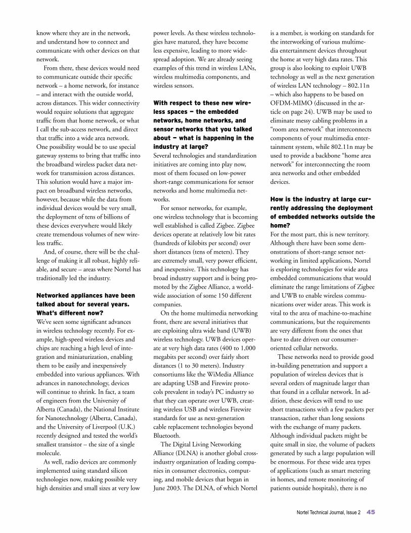
Nortel Technical Journal, Issue 2 45
know where they are in the network, and understand how to connect and communicate with other devices on that network.
From there, these devices would need to communicate outside their specific network – a home network, for instance – and interact with the outside world, across distances. This wider connectivity would require solutions that aggregate traffic from that home network, or what I call the sub-access network, and direct that traffic into a wide area network. One possibility would be to use special gateway systems to bring that traffic into the broadband wireless packet data net-work for transmission across distances. This solution would have a major im-pact on broadband wireless networks, however, because while the data from individual devices would be very small, the deployment of tens of billions of these devices everywhere would likely create tremendous volumes of new wire-less traffic.
And, of course, there will be the chal-lenge of making it all robust, highly reli-able, and secure – areas where Nortel has traditionally led the industry.
Networked appliances have been talked about for several years. What’s different now? We’ve seen some significant advances in wireless technology recently. For ex-ample, high-speed wireless devices and chips are reaching a high level of inte-gration and miniaturization, enabling them to be easily and inexpensively embedded into various appliances. With advances in nanotechnology, devices will continue to shrink. In fact, a team of engineers from the University of Alberta (Canada), the National Institute for Nanotechnology (Alberta, Canada), and the University of Liverpool (U.K.) recently designed and tested the world’s smallest transistor – the size of a single molecule.
As well, radio devices are commonly implemented using standard silicon technologies now, making possible very high densities and small sizes at very low
power levels. As these wireless technolo-gies have matured, they have become less expensive, leading to more wide-spread adoption. We are already seeing examples of this trend in wireless LANs, wireless multimedia components, and wireless sensors.
With respect to these new wire-less spaces — the embedded networks, home networks, and sensor networks that you talked about — what is happening in the industry at large? Several technologies and standardization initiatives are coming into play now, most of them focused on low-power short-range communications for sensor networks and home multimedia net-works.
For sensor networks, for example, one wireless technology that is becoming well established is called Zigbee. Zigbee devices operate at relatively low bit rates (hundreds of kilobits per second) over short distances (tens of meters). They are extremely small, very power efficient, and inexpensive. This technology has broad industry support and is being pro-moted by the Zigbee Alliance, a world-wide association of some 150 different companies.
On the home multimedia networking front, there are several initiatives that are exploiting ultra wide band (UWB) wireless technology. UWB devices oper-ate at very high data rates (400 to 1,000 megabits per second) over fairly short distances (1 to 30 meters). Industry consortiums like the WiMedia Alliance are adapting USB and Firewire proto-cols prevalent in today’s PC industry so that they can operate over UWB, creat-ing wireless USB and wireless Firewire standards for use as next-generation cable replacement technologies beyond Bluetooth.
The Digital Living Networking Alliance (DLNA) is another global cross-industry organization of leading compa-nies in consumer electronics, comput-ing, and mobile devices that began in June 2003. The DLNA, of which Nortel
is a member, is working on standards for the interworking of various multime-dia entertainment devices throughout the home at very high data rates. This group is also looking to exploit UWB technology as well as the next generation of wireless LAN technology – 802.11n – which also happens to be based on OFDM-MIMO (discussed in the ar-ticle on page 24). UWB may be used to eliminate messy cabling problems in a “room area network” that interconnects components of your multimedia enter-tainment system, while 802.11n may be used to provide a backbone “home area network” for interconnecting the room area networks and other embedded devices.
How is the industry at large cur-rently addressing the deployment of embedded networks outside the home?For the most part, this is new territory. Although there have been some dem-onstrations of short-range sensor net-working in limited applications, Nortel is exploring technologies for wide area embedded communications that would eliminate the range limitations of Zigbee and UWB to enable wireless commu-nications over wider areas. This work is vital to the area of machine-to-machine communications, but the requirements are very different from the ones that have to date driven our consumer- oriented cellular networks.
These networks need to provide good in-building penetration and support a population of wireless devices that is several orders of magnitude larger than that found in a cellular network. In ad-dition, these devices will tend to use short transactions with a few packets per transaction, rather than long sessions with the exchange of many packets. Although individual packets might be quite small in size, the volume of packets generated by such a large population will be enormous. For these wide area types of applications (such as smart metering in homes, and remote monitoring of patients outside hospitals), there is no

current standards activity. Nortel is look-ing to develop the technologies, and we will move those forward into standards when and as required.
Certainly low-power networks are among the new spaces for wire-less, but what technology advanc-es do you expect in the wireless core and access areas? We expect a number of developments and innovations in these areas: • Continued advances in miniaturization are the key to allow systems such as base stations to shrink to PC-size dimensions compared to today’s much larger racks and equipment shelves. This miniatur-ization, combined with lower costs, will open new and more flexible avenues to deployment, where base stations, for example, can be easily mounted on the masthead next to the antenna rather than on a remote base station, as is the case today.• Advances in power amplifiers will help to further lower costs. We are already leaders in this area, with multi-carrier linear power amplifier technology, as well as RF and digital integrated circuits that are enabling us to deliver the most compact low-cost solutions for cellular networks. We’ve developed a power amplifier that is 30-percent efficient (compared to today’s 12-15 percent ef-ficiency), and are currently developing a radically new technology that will lead to a 50-60 percent efficiency improve-ment.• Antenna technology innovation, such as our OFDM-MIMO technology, will enable higher capacities at lower costs for large-throughput wireless systems. Coming next is the use of new materi-als, such as metamaterials, which we are developing in conjunction with the University of Toronto (Canada), to en-able antennas to continue to shrink in size and cost. • MIMO technologies for future link-based and collaborative MIMO sys-tems will continue to lead to greater performance and simplicity. In this area, we have ongoing collaborative pro-
grams with the University of Waterloo (Ontario, Canada) and the Russian Academy of Science–MERA. • New security solutions will address the challenges posed by machine-to-machine communications. Because each embed-ded wireless device will be responsible for defending itself, traditional security models in the wired world – which use special firewalls to control access at the edge of the network and centralized entities for authentication and valida-tion – won’t apply. The best way to establish trust and security in these ad-hoc embedded networks is currently an open research question. To answer this question, we have begun working with several university partners, including the WINLAB (Wireless Information Network Laboratory) cooperative re-search center at Rutgers University in New Jersey. • Innovations in spectral utilization will make better use of the available spec-trum. The amount of suitable spectrum is certainly finite, and we can’t assume that large chunks of unused spectrum will be found. That’s why many com-panies, including Nortel, are exploring more efficient ways to use the existing spectrum. Today, spectrum is allocated exclusively to individual services (such as fire, police, and cellular services) in a given region. But if you were to sample the spectrum being used in these bands, you would find that in the spectrum below 10 GHz, less than 3 percent is being used at any time. If these radio frequency bands could be shared among the various services and users, we could significantly increase spectrum utiliza-tion.• Cognitive radio technology has the po-tential to give us much greater through-put and coverage, as well as increase spectrum utilization by ten times. With this technology, radios will “exercise judgement” to determine which slots of spectrum are available; which frequency, power level, transmission format, and protocol are required; and which mecha-nisms to use to avoid interference. We’re pursuing this “cognitive” capability and
in fact have introduced a rudimentary form of this capability for the U.S. market, on our Wireless Mesh Network solution. In the U.S., spectrum was re-cently allocated in the 5.5 to 5.85 GHz range (unlicensed band) for wireless LANs. Because this band is shared by military radar services, we had to build in the condition that all radar traffic must receive priority transmission, so that the radio can shift the wireless LAN traffic to a different frequency as soon as it receives a higher-priority radar signal.
What lies beyond the next five to ten years? Things move so quickly, it’s very dif-ficult to predict. In the mid-1980s, we grappled with how to best deliver 8 kilo-bits per second voice to the mobile user. Twenty years later, nearly two billion mobile users in the world have access to wireless communications at speeds as high as 3 megabits or so per second. It is safe to say that wireless communications will continue to permeate every aspect of our lives and fundamentally enhance the way we communicate. There is much more room for technology innovation heading into the next decade and Nortel is very well positioned – having played a major role in shaping wireless technol-ogy for the past 20 years – to address the technology challenges in front of us.
Nortel’s Al Javed, most recently the Leader of the company’s Wireless Advanced Technology program, will retire in September of this year. In his 28-year career with Nortel, Al played a key role in the development of innovations across all major wireless technologies, including in the areas of TDMA wireless systems, highly integrated wideband transceivers, advanced linear power amplifiers, smart antennas, and OFDM-MIMO for broad-band wireless and wireless mesh networks. Until his retirement, Al continues to nur-ture the teams working on the next innova-tions for wireless technology.
46 Nortel Technical Journal, Issue 2

Nortel Technical Journal, Issue 2 47
Simon Brueckheimer, an architect in Nortel’s Harlow (U.K.) laboratories, has been awarded the Royal Academy of Engineering Silver Medal. This honor is granted annually to only four engineers across Great Britain, under the age of 50, who have made outstanding contri-butions to British engineering.
At the awards ceremony in London in June, Simon was recognized as one of the U.K.’s leading communications en-gineers for his prolific patents portfolio – 46 filed, 40 granted to date – and spe-cifically for his foundational inventions that are central to the development of next-generation networks.
For instance, Simon conceived of a novel method of separating call rout-ing and connection control, as well as a method of performing frame syn-chronization in packet networks. Other patents encompass using the packet
NewsbriefsThe U.K.’s Royal Academy of Engineering awards prestigious Silver Medal to Nortel employee Simon Brueckheimer
network dynamically to send voice communications, as well as unbundling services and moving them to servers accessed by a single core network, pav-ing the way for simple and cost-effective delivery of broadband and new multi-media services. One particular patent, in fact, has been cited no less than 19
times in subsequent U.S.-granted applications.
These innovations have revolution-ized the design of communications networks, says Philip Hargrave, Nortel’s Chief Scientist for Europe, Middle East, and Africa (EMEA) and a Fellow of the Royal Academy. “Simon’s innovations have led to a new range of products for Nortel, and have contributed to the industry’s body of knowledge, with ideas that are now universally accepted under the banner of next-generation networks.”
Simon, who joined Nortel in 1986, continues his work at Nortel both in a customer-facing role with the sales com-munity and as a key member of Nortel’s advanced technology community, working on architectures and product strategies for both wireless and wireline networks.
Kelly Krick, Nortel’s customer opera-tions leader for the Cingular Wireless account in Atlanta, Georgia, recently received the IEEE’s Communications Quality & Reliability Chairman’s Award at a ceremony during the organization’s annual workshop in St. Petersburg, Florida.
In receiving the award, Kelly was cited for his sustained contributions in the fields of network system quality, overseeing the publication of valuable technical materials, and bridge- building throughout the international community.
Kelly has been involved with the IEEE Communications Quality & Reliability Technical Committee for the past 18 years. A former chairman of the committee, he has played a major role
Nortel’s Kelly Krick recognized with IEEE Communications Quality & Reliability Chairman’s Award
in organizing the committee’s annual workshops – and most notably, in ex-tending participation to the internation-al community by organizing workshops in Japan and Greece. The workshops ex-plore leading-edge ideas about what the telecommunications industry should be
doing to address the issues of emerging networks. Past workshops have focused on such key issues as software quality as-surance, TL 9000 specifications, and the Federal Communications Commission (FCC) mandates on outage tracking.
Kelly began his career at Nortel in 1984 doing proposals during the height of Nortel’s efforts to install digital switches into RBOC (Regional Bell Operating Company) networks in the United States. Kelly’s prior roles at Nortel included network engineering, software quality assurance, and total quality management in support of vari-ous business units and in various loca-tions. With his engineering background, Kelly says his greatest personal satisfac-tion comes from working with custom-ers to solve network issues.

Copyright © 2005 Nortel Networks. All rights reserved.
The following trademarks appear in this issue: Nortel is a trademark of Nortel. 3GPP is a trademark of the European Telecommunications Standards Institute. BlackBerry is a trademark of Research in Motion Limited. Bluetooth is a trademark of Bluetooth Sig, Inc. Firewire is a trademark of Apple Computer, Inc. MeshPlanner is a trademark of Wireless Valley Communications. Microsoft Windows is a trademark of Microsoft Corporation. Zigbee is a trademark of Philips Electronics North America Corporation.
The photographs on pages 4 and 43 were taken by Mike Pinder; and the photo at the top of page 47 by RAEng/Mark Crick.
THIS IS THE WAY
THIS IS