Embed Size (px)
Citation preview

1-800-4 NORTELwww.nortel.com/norstar
Norstar is a trademark of Northern Telecom.P0869547 Issue 02 Printed in Canada
Norstar is a trademark of Northern Telecom.
Copyright Northern Telecom, 1997
Norstar Applications Module II Installation and Maintenance Manual
This document was created with FrameBuilder 4.0.4

Installation and Maintenance Manual Norstar Applications Module II (NAM II)
Contents
Regulatory information viiRepair facilities viiiIntroduction 1How this manual is organized 1
Chapter 1 How to use this manual 1Knowing the symbols 2
NAM II Components 3
Chapter 2 Components of the NAM II 5NAM II upgrades 6
Hardware components of the NAM II 6Single Board Computer (SBC) 7Digital Voice Cards (DVC) 8Hard disk drive 8Floppy disk drive 8Power supply 8Ports 9
Optional equipment 11About the System software 12
Installing the NAM II 13
Chapter 3 Installing the NAM II 15Introduction 15
Station ports versus Voice Channels 15Before you start 15
Packaging Checklist 15Environment Checklist 16Electrical Checklist 16
Special parts and equipment 17Other documentation 17
Installation overview 17Changing the power supply voltage 18
ii
Norstar Applications Module II (NAM II) Installation and Maintenance Manual
Mounting on the wall 18Floor mount stand 20
Assembling the floor mount stand 20Attaching the floor mount stand to the NAM II 20Installing the end-caps 22
Connecting to the KSU 22Connecting the internal modem 24Powering up the NAM II 24
NAM II Hardware Upgrades and Replacements 25
Chapter 4 Preparing for the upgrade 27Overview 27Special tools 28Shutting down the NAM II 29Accessing the inside of the NAM II 30
Removing the front cover 31Opening the cable trough 32Removing the plastic case 32
Overview 35Removing and replacing the battery 35
Chapter 5 Installing the clock/calendar battery 35Overview 39
Chapter 6 Installing the Digital Fax Card (DFC) 39Precautions 40Installing the DFC 40Connecting the DFC to the DVCs with the PEB Cable 42Upgrading the DFC 46Installing the DFC expansion card 47Removing fax functionality from the System 48
Overview 51Increasing the number of Voice Channels 51 Types of DVCs 51
iii
Installation and Maintenance Manual Norstar Applications Module II (NAM II)
Chapter 7 Installing and upgrading the Digital Voice Cards (DVC)s 51Installing the second, third or fourth DVC 52Connecting a DVC to the distribution block 55Installing the first DVC 56Removing the second, third or fourth DVC 58Removing the first DVC 60Adding a DVC after a DFC is installed 62
Overview 65Installing a new floppy disk drive 65
Chapter 8 Installing a new floppy disk drive 65Overview 67
Backing up the NAM II capabilities file 67
Chapter 9 Installing and upgrading the hard disk drive 67Removing the hard disk drive 68Installing a new hard disk drive 70Restoring the NAM II capabilities file 71
Adding a secondary hard disk drive 72Overview 75
Removing the internal modem 75
Chapter 10 Installing a new Internal modem 75Installing a new internal modem 76Connecting the internal modem to an Analog Terminal Adapter (ATA) 78Overview 79Adding memory 79
Chapter 11 Adding and replacing memory 79Removing memory 83Overview 87Installing the SVGA video card 87
Chapter 12 Adding and removing a monitor, keyboard and mouse 87Installing the SVGA video card on the SBC 89
Enabling the monitor, keyboard and mouse 93Removing the monitor, keyboard and mouse 95Overview 97
iv
Norstar Applications Module II (NAM II) Installation and Maintenance Manual
Chapter 13 Changing the power supply voltage 97Changing the power supply voltage 98Overview 101
Chapter 14 Installing and replacing the Single Board Computer (SBC) 101Removing and replacing the SBC 102
ACCESS Server Administration 105
Chapter 15 Preparing to use the ACCESS Server administration software 107Overview 107Using an RS-232 terminal or laptop PC 108
Using terminal emulation 108Connecting an RS-232 terminal or laptop computer 108
Using the Server administration software from the NAM II monitor 110
Connecting a printer to the NAM II 110Remote access 110
Chapter 16 Using the ACCESS Server administration software from a terminal 113Overview 113Administering an application 115
Changing the printer options 116Viewing the Alarm and Message Log 117Allocating Voice and Fax Channels 117Installing and removing applications 119Changing the ACCESS Server Password 120Backing up and restoring the capabilities file 121
Shutting down the NAM II 121Rebooting the NAM II 122Server Diagnostics 124System password control 125
Chapter 17 Using the ACCESS Server administration software from a telephone set 127Overview 127Changing the printer options 127Setting the DTMF digit duration length 128Viewing the Alarm and Message Log 129
v
Installation and Maintenance Manual Norstar Applications Module II (NAM II)
Sharing Voice and Fax Channels between applications 130Installing applications 132Viewing the NAM II serial number 133Shutting down the NAM II 134Rebooting the NAM II 135
Scheduling a reboot of the NAM II 136
Troubleshooting 137
Chapter 18 Troubleshooting 139Overview 139Diagnosing problems 140
Hardware problems 140Checking the Channel Status 142Disabling and Re-enabling Norstar Voice Mail Channels 145
Preparing the NAM II for travel 147
Glossary 149
Index 155

vi
Norstar Applications Module II (NAM II) Installation and Maintenance Manual
Regulatory information
vii
Installation and Maintenance Manual Norstar Applications Module II (NAM II)
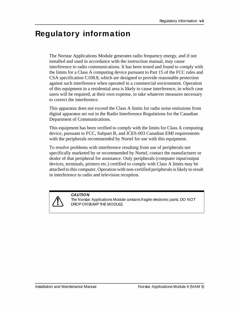
The Norstar Applications Module generates radio frequency energy, and if not installed and used in accordance with the instruction manual, may cause interference to radio communications. It has been tested and found to comply with the limits for a Class A computing device pursuant to Part 15 of the FCC rules and CSA specification C108.8, which are designed to provide reasonable protection against such interference when operated in a commercial environment. Operation of this equipment in a residential area is likely to cause interference, in which case users will be required, at their own expense, to take whatever measures necessary to correct the interference.
This apparatus does not exceed the Class A limits for radio noise emissions from digital apparatus set out in the Radio Interference Regulations for the Canadian Department of Communications.
This equipment has been verified to comply with the limits for Class A computing device, pursuant to FCC, Subpart B, and ICES-003 Canadian EMI requirements with the peripherals recommended by Nortel for use with this equipment.
To resolve problems with interference resulting from use of peripherals not specifically marketed by or recommended by Nortel, contact the manufacturer or dealer of that peripheral for assistance. Only peripherals (computer input/output devices, terminals, printers etc.) certified to comply with Class A limits may be attached to this computer. Operation with non-certified peripherals is likely to result in interference to radio and television reception.
Regulatory information
CAUTION
The Norstar Applications Module contains fragile electronic parts. DO NOT DROP OR BUMP THE MODULE.
This document was created with FrameBuilder 4.0.4
viii Regulatory information
Norstar Applications Module II (NAM II) Installation and Maintenance Manual
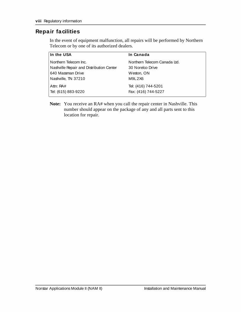
Repair facilitiesIn the event of equipment malfunction, all repairs will be performed by Northern Telecom or by one of its authorized dealers.
Note: You receive an RA# when you call the repair center in Nashville. This number should appear on the package of any and all parts sent to this location for repair.
In the USA In Canada
Northern Telecom Inc.Nashville Repair and Distribution Center640 Massman DriveNashville, TN 37210
Northern Telecom Canada Ltd. 30 Norelco DriveWeston, ONM9L 2X6
Attn: RA#Tel: (615) 883-9220
Tel: (416) 744-5201Fax: (416) 744-5227
Installation and Maintenance Manual Norstar Applications Module II (NAM II)
IntroductionThe Norstar Applications Module II (NAM II) Installation and Maintenance Manual provides technical information and procedures required by a technician to install the NAM II and perform various replacement and upgrade tasks. This manual is useful during and after an initial installation.
To use this manual, you should be:
• an experienced Norstar installer
• familiar with basic Norstar terminology
How this manual is organizedThe NAM II Maintenance Manual is organized in five sections that cover:
NAM II Components — This section provides an overview and functional description of NAM II hardware, a description of the hardware components, and shows where the components are located.
Installing the NAM II — This section provides the steps necessary to install a NAM II.
NAM II Hardware Upgrades and Replacements — This section provides the steps necessary for upgrading or replacing various NAM II components.
ACCESS Server administration — This section explains how to use the ACCESS Server administration software for a variety of maintenance functions.
Troubleshooting — This section provides procedures for diagnosing and solving problems concerning the NAM II.
How to use this manual 1
2 How to use this manual
Norstar Applications Module II (NAM II) Installation and Maintenance Manual
Knowing the symbolsThis manual uses certain symbols to draw your attention to important information. You should pay attention to the following:
Note: A Note alerts you to information that is particularly critical or noteworthy.
Caution Symbol
Alerts you to situations where there is the possibility of damaging the equipment.
Warning Symbol
Alerts you to situations where there is the possibility of injuring yourself
Alerts you to remove the NAM II power cord from the AC outlet before performing the maintenance procedure.
Alerts you to ground yourself before performing the maintenance procedure.
Installation and Maintenance Manual Norstar Applications Module II (NAM II)
Section I - NAM II Components
• Components of the NAM II• NAM II System software

4 NAM II Components
Norstar Applications Module II (NAM II) Installation and Maintenance Manual
Installation and Maintenance Manual Norstar Applications Module II (NAM II)
Components of the NAM II
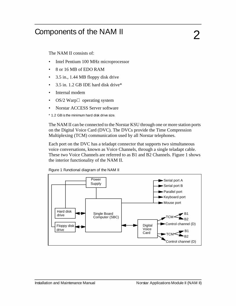
The NAM II consists of:
• Intel Pentium 100 MHz microprocessor
• 8 or 16 MB of EDO RAM
• 3.5 in., 1.44 MB floppy disk drive
• 3.5 in. 1.2 GB IDE hard disk drive*
• Internal modem
• OS/2 Warp operating system
• Norstar ACCESS Server software
* 1.2 GB is the minimum hard disk drive size.
The NAM II can be connected to the Norstar KSU through one or more station ports on the Digital Voice Card (DVC). The DVCs provide the Time Compression Multiplexing (TCM) communication used by all Norstar telephones.
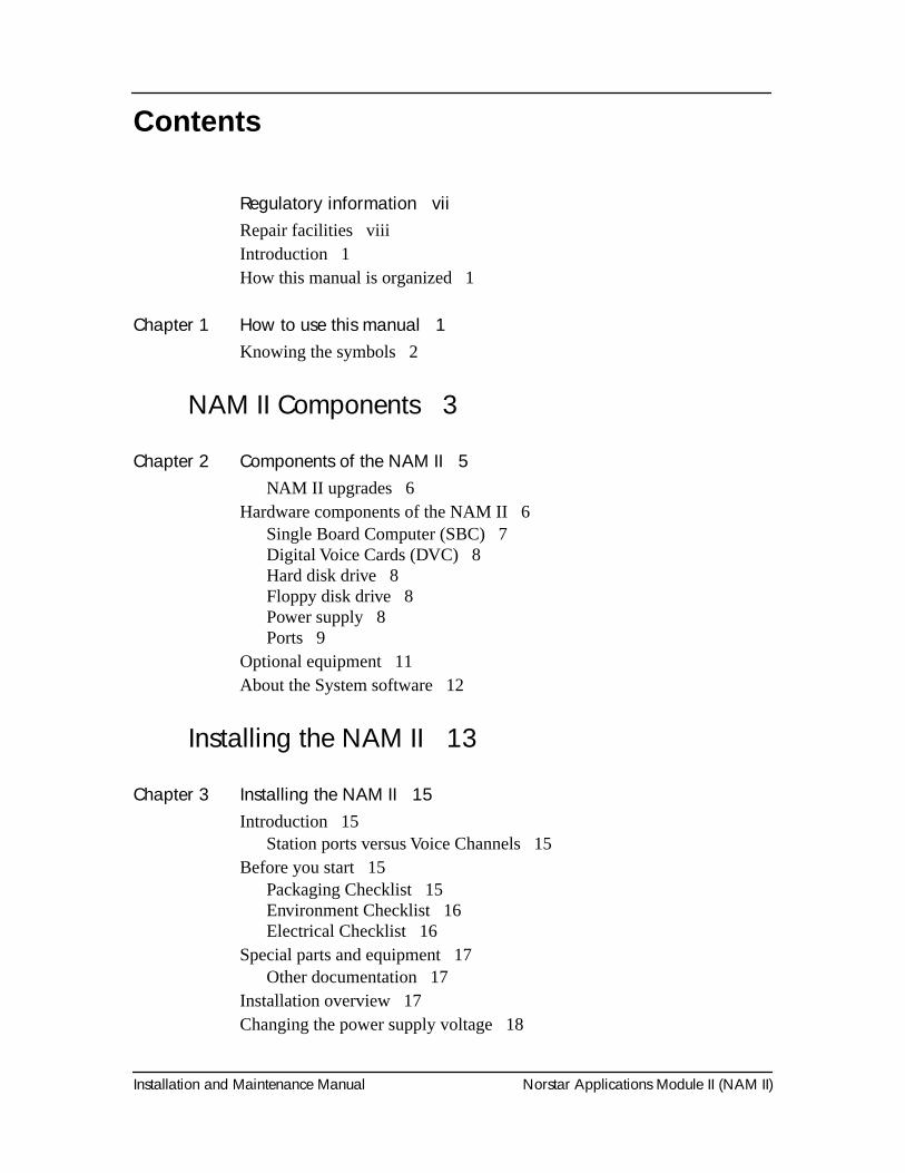
Each port on the DVC has a teladapt connector that supports two simultaneous voice conversations, known as Voice Channels, through a single teladapt cable. These two Voice Channels are referred to as B1 and B2 Channels. Figure 1 shows the interior functionality of the NAM II.
Figure 1 Functional diagram of the NAM II
2
Hard disk drive
Floppy diskdrive
Single Board
Serial port B
Parallel port
Keyboard port
Mouse port
DigitalVoiceCard
TCMB1
B2Control channel (D)
TCMB1
B2
Control channel (D)
Serial port APower Supply
Computer (SBC)
6 Components of the NAM II
Norstar Applications Module II (NAM II) Installation and Maintenance Manual
NAM II upgradesThe NAM II can be upgraded to host a variety of hardware and software configurations. You can enhance functionality by adding more Voice Channels. Refer to "NAM II Hardware Upgrades and Replacements" on page 25 for more information about upgrading your NAM II.
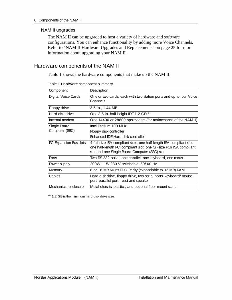
Hardware components of the NAM IITable 1 shows the hardware components that make up the NAM II.
Table 1 Hardware component summary
** 1.2 GB is the minimum hard disk drive size.
Component DescriptionDigital Voice Cards One or two cards, each with two station ports and up to four Voice
Channels
Floppy drive 3.5 in., 1.44 MBHard disk drive One 3.5 in. half-height IDE 1.2 GB**Internal modem One 14400 or 28800 bps modem (for maintenance of the NAM II)Single Board Computer (SBC)
Intel Pentium 100 MHzFloppy disk controllerEnhanced IDE Hard disk controller
PC Expansion Bus slots 4 full-size ISA compliant slots, one half-length ISA compliant slot, one half-length PCI compliant slot, one full-size PCI/ISA compliant slot and one Single Board Computer (SBC) slot
Ports Two RS-232 serial, one parallel, one keyboard, one mousePower supply 200W 115/230 V switchable, 50/60 HzMemory 8 or 16 MB 60 ns EDO Parity (expandable to 32 MB) RAMCables Hard disk drive, floppy drive, two serial ports, keyboard/mouse
port, parallel port, reset and speaker Mechanical enclosure Metal chassis, plastics, and optional floor mount stand
Components of the NAM II 7
Installation and Maintenance Manual Norstar Applications Module II (NAM II)
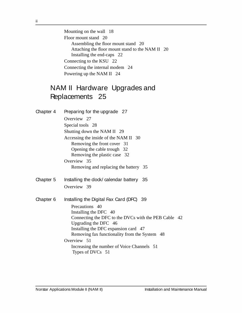
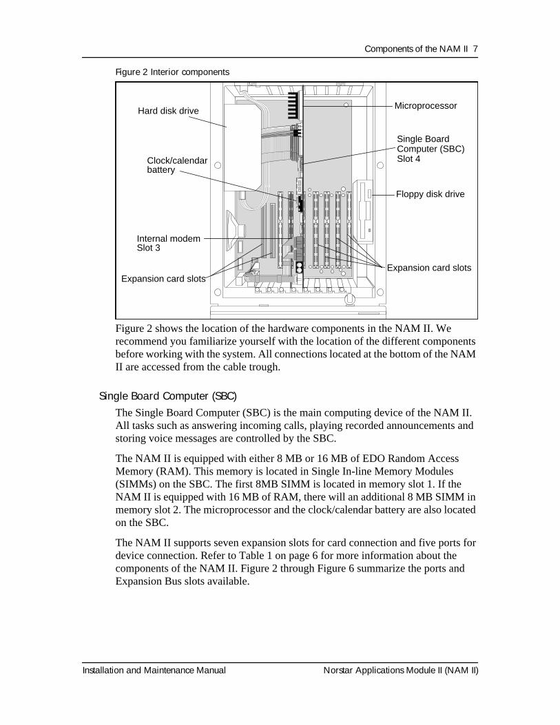
Figure 2 Interior components
Figure 2 shows the location of the hardware components in the NAM II. We recommend you familiarize yourself with the location of the different components before working with the system. All connections located at the bottom of the NAM II are accessed from the cable trough.
Single Board Computer (SBC)The Single Board Computer (SBC) is the main computing device of the NAM II. All tasks such as answering incoming calls, playing recorded announcements and storing voice messages are controlled by the SBC.
The NAM II is equipped with either 8 MB or 16 MB of EDO Random Access Memory (RAM). This memory is located in Single In-line Memory Modules (SIMMs) on the SBC. The first 8MB SIMM is located in memory slot 1. If the NAM II is equipped with 16 MB of RAM, there will an additional 8 MB SIMM in memory slot 2. The microprocessor and the clock/calendar battery are also located on the SBC.
The NAM II supports seven expansion slots for card connection and five ports for device connection. Refer to Table 1 on page 6 for more information about the components of the NAM II. Figure 2 through Figure 6 summarize the ports and Expansion Bus slots available.
1) Front View 1.6
Floppy disk drive
Expansion card slots
Hard disk drive
Clock/calendarbattery
Microprocessor
Internal modemSlot 3
Expansion card slots
Single Board Computer (SBC)Slot 4
8 Components of the NAM II
Norstar Applications Module II (NAM II) Installation and Maintenance Manual
Note: Expansion Bus slots 2, 5, 6 and 7 are allocated for DVCs and slot 8* for a Digital Fax Card (DFC). If a PCIB card or Norlink is used, a DVC cannot be present anywhere on the Expansion Bus.
*If Automatic Call Distribution (ACD) is installed on the system, slot 8 is reserved for the SVGA card. A DFC cannot be installed on a system with ACD.
Digital Voice Cards (DVC)The DVC is an expansion card that converts and compresses analog voice signals to digital data for storage on the hard disk. Each DVC provides the NAM II with four TCM Voice Channels. The DVC has two ports that each provide two Voice Channels (B1 and B2) and one control channel (D). The control channel is the NAM II’s physical connection to the Norstar KSU and allows the NAM II to send instructional messages to the KSU and vice versa. Channels on the DVC are enabled through a specific upgrade procedure. Refer to "Increasing the number of Voice Channels" on page 51 for more information about enabling DVC Channels.
Hard disk driveThe NAM II comes equipped with an IDE 3.5 inch hard disk with a minimum capacity of 1.2 GB. The hard disk drive stores all software, messages, greetings and voice prompts.
Note: To ensure your system programming is protected against a hardware failure, you must perform frequent backups of the hard disk drive. For more information about backing up your hard disk, refer to "Backing up the NAM II capabilities file" on page 67.
Floppy disk driveThe floppy disk drive on the NAM II is a 3.5 in., 1.44 MB drive. This drive is used to load programs and prompts from floppy disks onto the hard disk. It is also used for backup and restore procedures.
Power supplyThe power supply converts AC line voltage to DC. It provides ±5V DC and ±12V DC to the SBC and disk drives. The power supply is shipped with the default setting of 115 volts, but this setting can be changed to 230 volts. For more information about changing the default voltage setting, refer to "Changing the power supply voltage" on page 98.
Note: The NAM II is not equipped with an ON/OFF power switch. This module is designed for continual use; therefore we recommend that you do not use a switched power outlet.
Components of the NAM II 9
Installation and Maintenance Manual Norstar Applications Module II (NAM II)
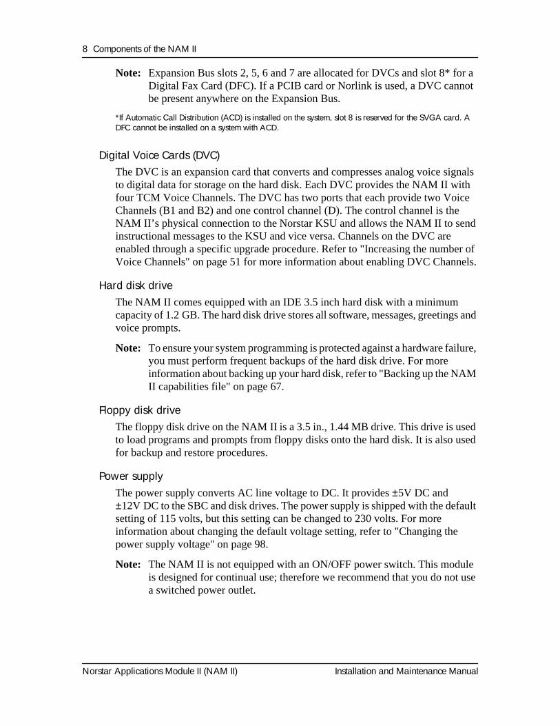
PortsExternal devices, such as a laptop computer, are attached to the NAM II through its ports. The ports are located on the bottom of the NAM II and are accessed through the cable trough. Figure 3 shows the location of the different ports.
Figure 3 Module external points of connection
Serial
The NAM II is equipped with two serial ports that support asynchronous RS-232C communication. Each port features a male DB-9 connector and supports all standard baud rates (9600 default). The serial ports are used to connect:
• an RS-232 terminal
• laptop computer
• a modem
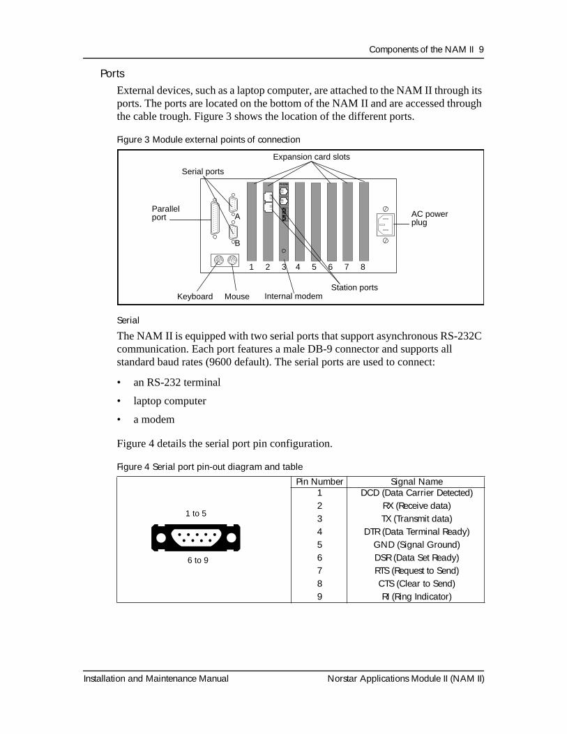
Figure 4 details the serial port pin configuration.
Figure 4 Serial port pin-out diagram and table
Pin Number Signal Name 123456789
DCD (Data Carrier Detected)RX (Receive data)TX (Transmit data)
DTR (Data Terminal Ready)GND (Signal Ground)DSR (Data Set Ready)RTS (Request to Send)CTS (Clear to Send)RI (Ring Indicator)
12
34
56
78Parallel
port
Serial ports
Expansion card slots
AC powerplug
Keyboard Mouse Station ports
1 2 3 4 5 6 7 8
A
B
Internal modem
1 to 5
6 to 9
10 Components of the NAM II
Norstar Applications Module II (NAM II) Installation and Maintenance Manual
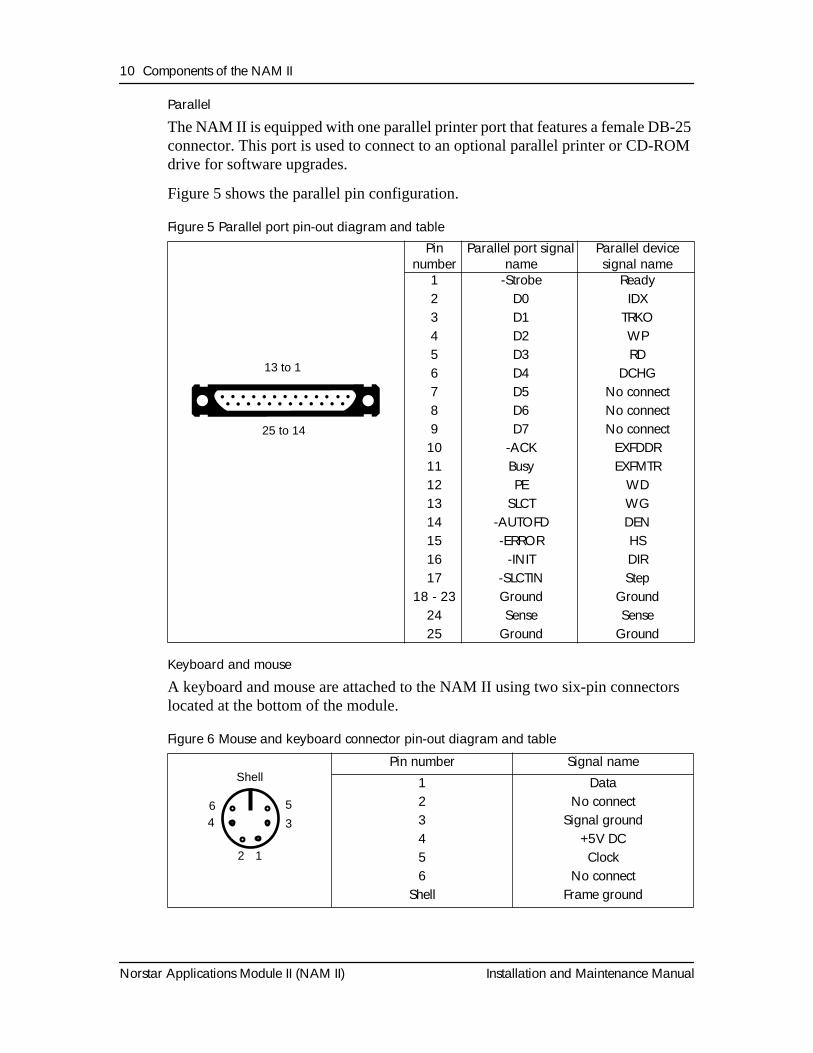
Parallel
The NAM II is equipped with one parallel printer port that features a female DB-25 connector. This port is used to connect to an optional parallel printer or CD-ROM drive for software upgrades.
Figure 5 shows the parallel pin configuration.
Figure 5 Parallel port pin-out diagram and table
Keyboard and mouse
A keyboard and mouse are attached to the NAM II using two six-pin connectors located at the bottom of the module.
Figure 6 Mouse and keyboard connector pin-out diagram and table
Pin number
Parallel port signal name
Parallel device signal name
1234567891011121314151617
18 - 232425
-StrobeD0D1D2D3D4D5D6D7
-ACKBusyPE
SLCT-AUTOFD-ERROR
-INIT-SLCTINGroundSense
Ground
ReadyIDX
TRKOWPRD
DCHGNo connectNo connectNo connect
EXFDDREXFMTR
WDWGDENHSDIRStep
GroundSense
Ground
Pin number Signal name123456
Shell
DataNo connect
Signal ground+5V DCClock
No connectFrame ground
13 to 1
25 to 14
64
2 1
Shell
5
3
Components of the NAM II 11
Installation and Maintenance Manual Norstar Applications Module II (NAM II)
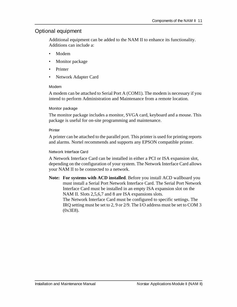
Optional equipmentAdditional equipment can be added to the NAM II to enhance its functionality. Additions can include a:
• Modem
• Monitor package
• Printer
• Network Adapter Card
Modem
A modem can be attached to Serial Port A (COM1). The modem is necessary if you intend to perform Administration and Maintenance from a remote location.
Monitor package
The monitor package includes a monitor, SVGA card, keyboard and a mouse. This package is useful for on-site programming and maintenance.
Printer
A printer can be attached to the parallel port. This printer is used for printing reports and alarms. Nortel recommends and supports any EPSON compatible printer.
Network Interface Card
A Network Interface Card can be installed in either a PCI or ISA expansion slot, depending on the configuration of your system. The Network Interface Card allows your NAM II to be connected to a network.
Note: For systems with ACD installed. Before you install ACD wallboard you must install a Serial Port Network Interface Card. The Serial Port Network Interface Card must be installed in an empty ISA expansion slot on the NAM II. Slots 2,5,6,7 and 8 are ISA expansions slots.The Network Interface Card must be configured to specific settings. The IRQ setting must be set to 2, 9 or 2/9. The I/O address must be set to COM 3 (0x3E8).
12 Components of the NAM II
Norstar Applications Module II (NAM II) Installation and Maintenance Manual
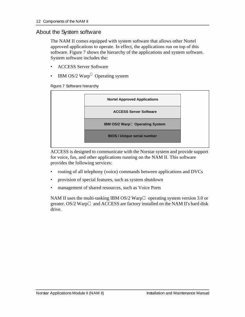
About the System softwareThe NAM II comes equipped with system software that allows other Nortel approved applications to operate. In effect, the applications run on top of this software. Figure 7 shows the hierarchy of the applications and system software. System software includes the:
• ACCESS Server Software
• IBM OS/2 Warp Operating system
Figure 7 Software hierarchy
ACCESS is designed to communicate with the Norstar system and provide support for voice, fax, and other applications running on the NAM II. This software provides the following services:
• routing of all telephony (voice) commands between applications and DVCs
• provision of special features, such as system shutdown
• management of shared resources, such as Voice Ports
NAM II uses the multi-tasking IBM OS/2 Warp operating system version 3.0 or greater. OS/2 Warp and ACCESS are factory installed on the NAM II's hard disk drive.
IBM OS/2 Warp Operating System
BIOS / Unique serial number
ACCESS Server Software
Nortel Approved Applications
Installation and Maintenance Manual Norstar Applications Module II (NAM II)
Section II - Installing the NAM II
• Mounting the NAM II on the wall• Mounting the NAM II on a floor mount stand
• Connecting to the NAM II to the KSU
14 Installing the NAM II
Norstar Applications Module II (NAM II) Installation and Maintenance Manual
Installation and Maintenance Manual Norstar Applications Module II (NAM II)
Installing the NAM II
IntroductionThis section is intended for the installer of the NAM II and describes how the system should be installed and prepared for operation.
Station ports versus Voice ChannelsThe NAM II is connected to the Norstar KSU through station ports. The station ports are located on the Digital Voice Cards (DVCs) within the module. These DVCs allow the NAM II to communicate with the KSU using Time Compression Multiplexing (TCM). Time Compression Multiplexing is used by all Norstar telephones.
The DVCs inside the NAM II each have two station ports for connection to the KSU. Each of these DVC station ports support two simultaneous Voice Channels, called B1 and B2. For example, one DVC with two station ports supports four simultaneous Voice Channels.
Before you startBefore you start the installation, ensure that you:
• read this guide and understand the installation process
• verify that all conditions are met in the checklists
Packaging ChecklistMake sure the package you received contains the following items:
❐ NAM II
❐ the NAM II wall mounting bracket
❐ an AC power cord
❐ a teladapt cord for each DVC station port
3
16 Installing the NAM II
Norstar Applications Module II (NAM II) Installation and Maintenance Manual
Environment ChecklistThe installation area must be:
❐ at least 4 m (approximately 13 feet) from equipment such as copiers, electrical motors and other equipment that could produce electromagnetic, radio frequency and electrostatic interferences
❐ within 305 m (approximately 1000 feet) of the Norstar KSU
❐ within 1.5 m (approximately 5 feet) of a three-wire grounded electrical outlet
❐ clean, free of traffic and excess dust, dry and well ventilated
❐ between 10° and 40° Celsius (approximately 50° to 104° Fahrenheit)
❐ between 8% and 80% non-condensing relative humidity
❐ a wall area approximately 1 m square (approximately 10 sq feet)
❐ a minimum of 16 cm (approximately 6 inches) from a corner wall or other component
❐ a minimum of 46 cm (approximately 18 inches) from the floor
Note: The distance from the floor to the installation area should be enough to prevent water damage.
Electrical Checklist
The electrical supply must be:
❐ 3rd wire ground
❐ unswitched
Note: The NAM II does not require a dedicated circuit. Do not connect the NAM II to an AC outlet on a circuit that is likely to be overloaded or used by large office equipment or power tools.
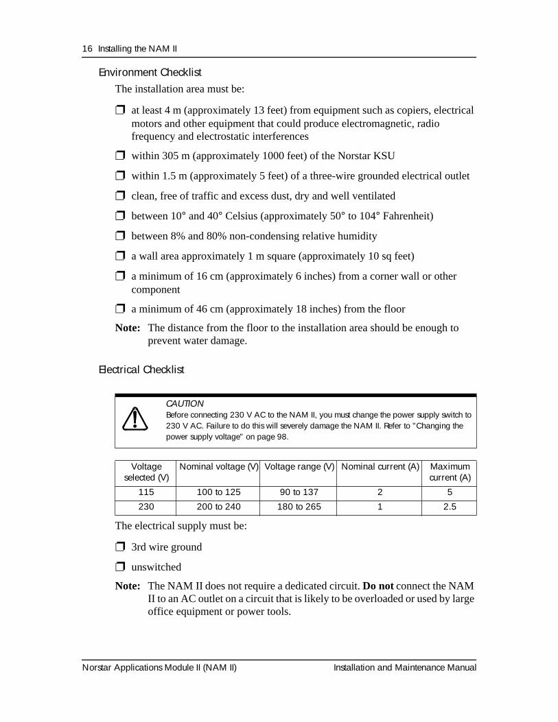
CAUTION
Before connecting 230 V AC to the NAM II, you must change the power supply switch to 230 V AC. Failure to do this will severely damage the NAM II. Refer to "Changing the power supply voltage" on page 98.
Voltage selected (V)
Nominal voltage (V) Voltage range (V) Nominal current (A) Maximum current (A)
115 100 to 125 90 to 137 2 5230 200 to 240 180 to 265 1 2.5
Installing the NAM II 17
Installation and Maintenance Manual Norstar Applications Module II (NAM II)
Special parts and equipmentFor the installation, you need the following equipment:
❐ Phillips #2 screwdriver
❐ power drill
❐ flat blade screwdriver
❐ antistatic grounding strap
❐ four #10 X 2.5 cm (#10 X 1 inch) round head wood screws
❐ twisted pair station wire
❐ plywood backboard 2 cm (3/4 inch) thick
❐ surge protector (recommended)
Other documentationIn addition to the documentation included in the package you received, the
Norstar Installation Guide that came with your Norstar KSU may also be necessary.
If your NAM II is equipped with a Media Services Base Interface Card (MSBIC), you will need to refer to the Media Services Base Interface Card Documentation Supplement.
This guide provides instructions on installing a Norstar station port if there are no free station ports available at the distribution block.
Installation overviewInstalling a NAM II involves the following:
• power supply switch setting (if required)
• mounting the unit on the wall
• connecting the station port(s)
• connecting the power cord
18 Installing the NAM II
Norstar Applications Module II (NAM II) Installation and Maintenance Manual
Changing the power supply voltageThe power supply on the NAM II is set at the factory to operate at 115 volts. If you plan to use 115 volts to power the NAM II, do not change the voltage switch. If you plan to use 230 volts to power the NAM II, you must change the power supply voltage setting before mounting the unit on the wall. Refer to "Changing the power supply voltage" on page 98.
Mounting on the wall
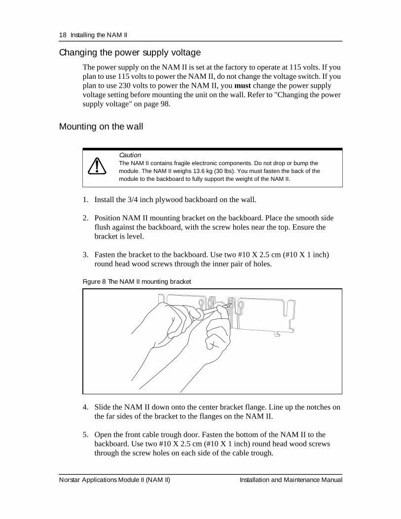
1. Install the 3/4 inch plywood backboard on the wall.
2. Position NAM II mounting bracket on the backboard. Place the smooth side flush against the backboard, with the screw holes near the top. Ensure the bracket is level.
3. Fasten the bracket to the backboard. Use two #10 X 2.5 cm (#10 X 1 inch) round head wood screws through the inner pair of holes.
Figure 8 The NAM II mounting bracket
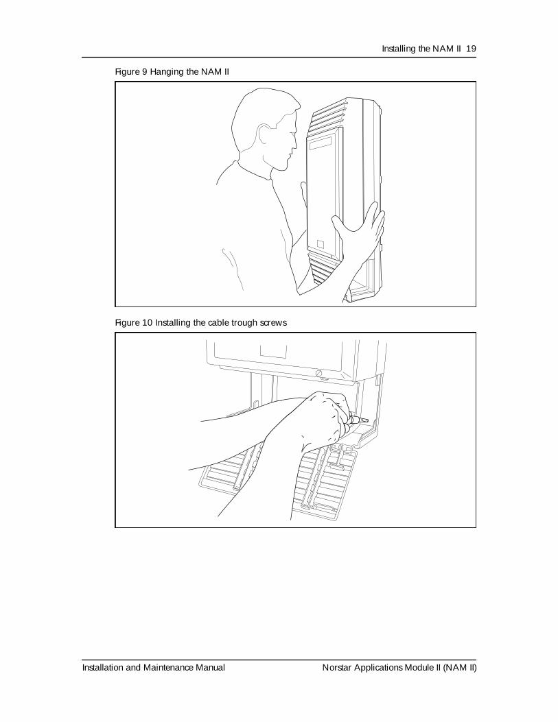
4. Slide the NAM II down onto the center bracket flange. Line up the notches on the far sides of the bracket to the flanges on the NAM II.
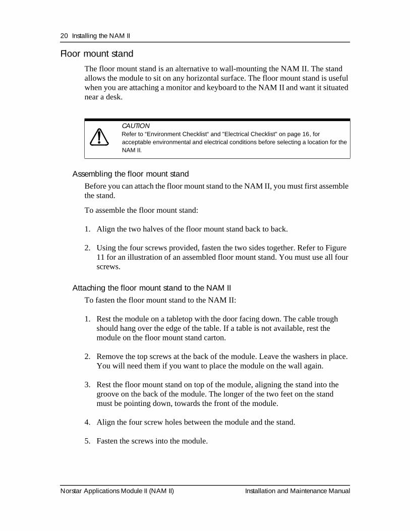
5. Open the front cable trough door. Fasten the bottom of the NAM II to the backboard. Use two #10 X 2.5 cm (#10 X 1 inch) round head wood screws through the screw holes on each side of the cable trough.
Caution
The NAM II contains fragile electronic components. Do not drop or bump the module. The NAM II weighs 13.6 kg (30 lbs). You must fasten the back of the module to the backboard to fully support the weight of the NAM II.
Installing the NAM II 19
Installation and Maintenance Manual Norstar Applications Module II (NAM II)
Figure 9 Hanging the NAM II
Figure 10 Installing the cable trough screws
20 Installing the NAM II
Norstar Applications Module II (NAM II) Installation and Maintenance Manual
Floor mount standThe floor mount stand is an alternative to wall-mounting the NAM II. The stand allows the module to sit on any horizontal surface. The floor mount stand is useful when you are attaching a monitor and keyboard to the NAM II and want it situated near a desk.
Assembling the floor mount standBefore you can attach the floor mount stand to the NAM II, you must first assemble the stand.
To assemble the floor mount stand:
1. Align the two halves of the floor mount stand back to back.
2. Using the four screws provided, fasten the two sides together. Refer to Figure 11 for an illustration of an assembled floor mount stand. You must use all four screws.
Attaching the floor mount stand to the NAM IITo fasten the floor mount stand to the NAM II:
1. Rest the module on a tabletop with the door facing down. The cable trough should hang over the edge of the table. If a table is not available, rest the module on the floor mount stand carton.
2. Remove the top screws at the back of the module. Leave the washers in place. You will need them if you want to place the module on the wall again.
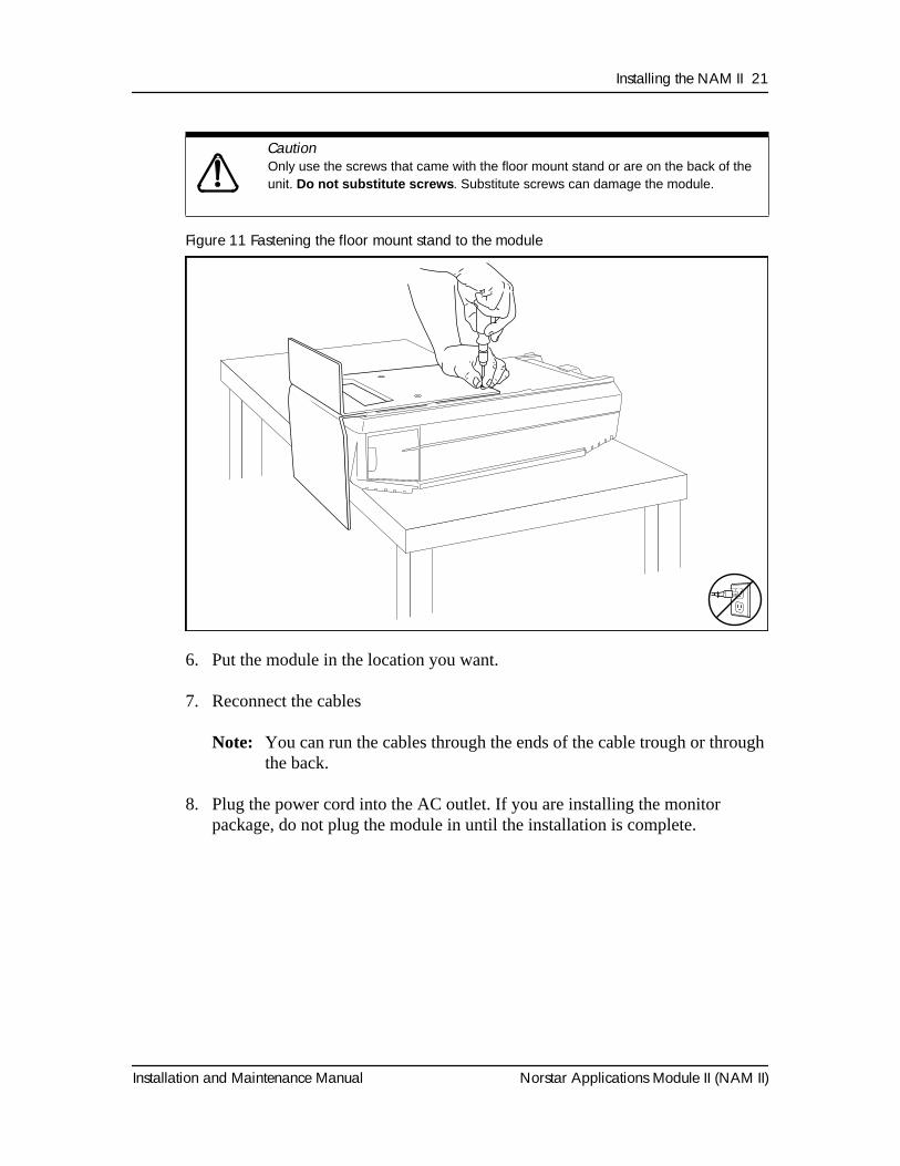
3. Rest the floor mount stand on top of the module, aligning the stand into the groove on the back of the module. The longer of the two feet on the stand must be pointing down, towards the front of the module.
4. Align the four screw holes between the module and the stand.
5. Fasten the screws into the module.
CAUTION
Refer to “Environment Checklist“ and "Electrical Checklist" on page 16, for acceptable environmental and electrical conditions before selecting a location for the NAM II.
Installing the NAM II 21
Installation and Maintenance Manual Norstar Applications Module II (NAM II)
Figure 11 Fastening the floor mount stand to the module
6. Put the module in the location you want.
7. Reconnect the cables
Note: You can run the cables through the ends of the cable trough or through the back.
8. Plug the power cord into the AC outlet. If you are installing the monitor package, do not plug the module in until the installation is complete.
Caution
Only use the screws that came with the floor mount stand or are on the back of the unit.
Do not substitute screws
. Substitute screws can damage the module.
22 Installing the NAM II
Norstar Applications Module II (NAM II) Installation and Maintenance Manual
Installing the end-capsTo install the end-caps:
1. Make sure the front cable trough door is open.
2. Place the bottom of the end-cap into the slot in the bottom of the trough. There are two end-caps, one for the left side, and one for the right side of the cable trough.
3. Slide the end-cap straight back to the end of the slot.
Connecting to the KSUBefore you begin connecting to the KSU, ensure a Norstar station port is available at the distribution block prior to booting the unit. For instructions on installing a station port , refer to the Norstar Installation Guide that came with the Norstar KSU.
To wire the NAM II to the KSU:
1. Locate the distribution block.
2. Ensure there is one station port available at the distribution block for each DVC station port. For instructions about installing a station port, refer to the Norstar Installation Guide that came with the Norstar KSU.
3. Mount the teladapt jacks next to the distribution block.
4. Using twisted pair station wire, connect the teladapt jacks to free station ports on the distribution block.
5. Test the port using a working Norstar telephone.
6. Connect one end of each teladapt connection cord to the appropriate DVC station ports. Connect the other end to the plug at the teladapt jack. Do not use a teladapt cord that is longer than 2.1 m (approximately 7 ft).
Note: If your NAM II came with RFI filters connected to the DVCs, you must connect the teladapt cord to the RFI filter that is connected to the DVC station port.
7. Norstar only uses the two center pins of a teladapt plug. For example, if you are using a Norstar standard six wire plug, only pin numbers three and four are used. All wiring and cabling should be run through the bottom or sides of the cable trough.
Installing the NAM II 23
Installation and Maintenance Manual Norstar Applications Module II (NAM II)
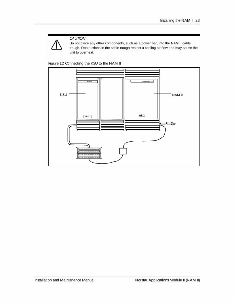
Figure 12 Connecting the KSU to the NAM II
CAUTION
Do not place any other components, such as a power bar, into the NAM II cable trough. Obstructions in the cable trough restrict a cooling air flow and may cause the unit to overheat.
NAM IIKSU
24 Installing the NAM II
Norstar Applications Module II (NAM II) Installation and Maintenance Manual
Connecting the internal modemAfter the NAM II has been mounted and connected to the KSU, the internal modem must be connected. The internal modem can either be connected to an Analog Terminal Adapter (ATA) or to an incoming Central Office (CO) line. The internal modem is used for NAM II maintenance only. This modem cannot be accessed by other users. Refer to "Connecting the internal modem to an Analog Terminal Adapter (ATA)" on page 78 for information on connecting the internal modem.
Powering up the NAM II
1. Plug in the NAM II. Wait until the self-diagnostics are completed. This can take up to five minutes. Read the power supply warning label, covering the AC power plug, before powering up the NAM II.
CAUTION
The power supply default setting is 115 volts. For more information about changing the power supply voltage setting, refer to "Changing the power supply voltage" on page 98.

Installation and Maintenance Manual Norstar Applications Module II (NAM II)
Section III - NAM II Hardware Upgradesand Replacements
• Preparing for the upgrade• Installing the clock/calendar battery
• Installing and upgrading the Digital Fax Card (DFC)• Installing and upgrading the Digital Voice Cards (DVC)s
• Installing a new floppy disk drive• Installing and upgrading the hard disk drive
• Installing a new internal modem• Adding and replacing memory
• Adding or removing a monitor, keyboard and mouse• Changing the power supply voltage
• Installing or replacing the Single Board Computer (SBC)
26 NAM II Hardware Upgrades and Replacements
Norstar Applications Module II (NAM II) Installation and Maintenance Manual
Installation and Maintenance Manual Norstar Applications Module II (NAM II)
Preparing for the upgrade
OverviewHardware upgrades to the NAM II are required when additional capacity or functionality is needed. This section describes upgrade or replacement procedures for the following:
• clock/calendar battery
• Digital Fax Card (DFC)*
• Digital Voice Cards (DVC) and Voice Channels
• floppy disk drive
• hard disk drive
• internal modem
• memory
• monitor, keyboard and mouse
• Single Board Computer (SBC)
*Only on systems with applications that support FAX functionality. For example, Norstar Voice Mail.
Refer to Figure 2 on page 7 for the location of the NAM II interior components.
Note: The power supply is not a field replaceable part.
4
28 Preparing for the upgrade
Norstar Applications Module II (NAM II) Installation and Maintenance Manual
Special toolsBefore you begin replacing or upgrading the components, ensure you have the following equipment:
• #2 Phillips head screwdriver that has a blade 3.5 in. long
• 3/16 in. slot screwdriver
• an antistatic grounding strap
• 3/16 in. nut driver (recommended)
CAUTION
You must wear an antistatic grounding strap at all times when handling electronic components. Failure to do so may result in damage to the equipment.
Preparing for the upgrade 29
Installation and Maintenance Manual Norstar Applications Module II (NAM II)
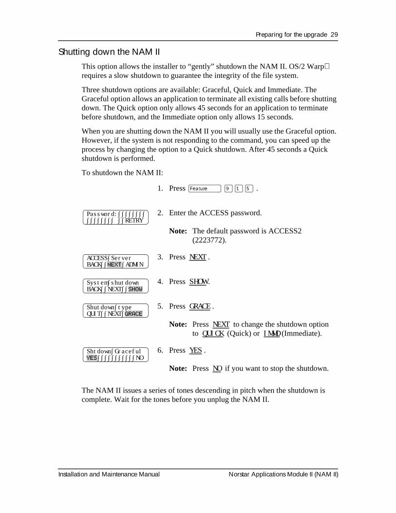
Shutting down the NAM IIThis option allows the installer to “gently” shutdown the NAM II. OS/2 Warp requires a slow shutdown to guarantee the integrity of the file system.
Three shutdown options are available: Graceful, Quick and Immediate. The Graceful option allows an application to terminate all existing calls before shutting down. The Quick option only allows 45 seconds for an application to terminate before shutdown, and the Immediate option only allows 15 seconds.
When you are shutting down the NAM II you will usually use the Graceful option. However, if the system is not responding to the command, you can speed up the process by changing the option to a Quick shutdown. After 45 seconds a Quick shutdown is performed.
To shutdown the NAM II:
The NAM II issues a series of tones descending in pitch when the shutdown is complete. Wait for the tones before you unplug the NAM II.
1. Press
ƒ ·⁄fi
.
2. Enter the ACCESS password.
Note:
The default password is ACCESS2 (2223772).
3. Press
NEXT
.
4. Press
SHOW
.
5. Press
GRACE
.
Note:
Press
NEXT
to change the shutdown option to
QUICK
(Quick) or
IMMD
(Immediate).
6. Press
YES
.
Note:
Press
NO
if you want to stop the shutdown.
Password:∫∫∫∫∫∫∫∫∫∫∫∫∫∫∫∫ ∫∫RETRY
ACCESS∫ServerBACK∫∫
NEXT
∫ADMIN
System∫shutdownBACK∫∫NEXT∫∫
SHOW
Shutdown∫typeQUIT∫∫NEXT∫
GRACE
Shtdown∫Graceful
YES
∫∫∫∫∫∫∫∫∫∫∫NO
30 Preparing for the upgrade
Norstar Applications Module II (NAM II) Installation and Maintenance Manual
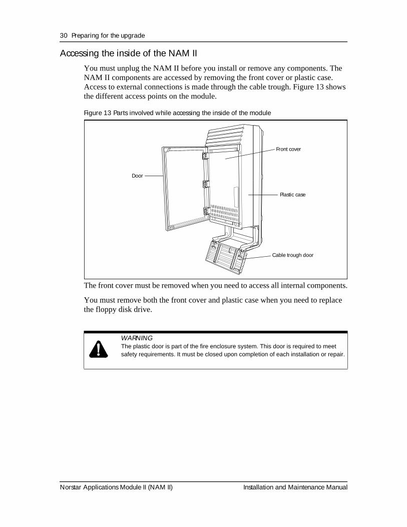
Accessing the inside of the NAM IIYou must unplug the NAM II before you install or remove any components. The NAM II components are accessed by removing the front cover or plastic case. Access to external connections is made through the cable trough. Figure 13 shows the different access points on the module.
Figure 13 Parts involved while accessing the inside of the module
The front cover must be removed when you need to access all internal components.
You must remove both the front cover and plastic case when you need to replace the floppy disk drive.
WARNING
The plastic door is part of the fire enclosure system. This door is required to meet safety requirements. It must be closed upon completion of each installation or repair.
Door
Front cover
Plastic case
Cable trough door
Preparing for the upgrade 31
Installation and Maintenance Manual Norstar Applications Module II (NAM II)
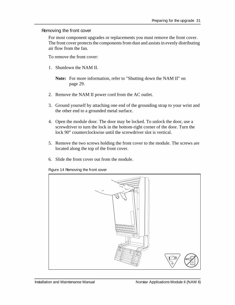
Removing the front coverFor most component upgrades or replacements you must remove the front cover. The front cover protects the components from dust and assists in evenly distributing air flow from the fan.
To remove the front cover:
1. Shutdown the NAM II.
Note: For more information, refer to "Shutting down the NAM II" on page 29.
2. Remove the NAM II power cord from the AC outlet.
3. Ground yourself by attaching one end of the grounding strap to your wrist and the other end to a grounded metal surface.
4. Open the module door. The door may be locked. To unlock the door, use a screwdriver to turn the lock in the bottom-right corner of the door. Turn the lock 90° counterclockwise until the screwdriver slot is vertical.
5. Remove the two screws holding the front cover to the module. The screws are located along the top of the front cover.
6. Slide the front cover out from the module.
Figure 14 Removing the front cover
32 Preparing for the upgrade
Norstar Applications Module II (NAM II) Installation and Maintenance Manual
To replace the front cover:
1. Insert the tongues on the bottom of the front cover into the module slots.
2. Fasten the two screws holding the front cover to the module.
3. Close the module door. To lock the door, turn the lock 90° clockwise until the screwdriver slot is horizontal.
4. Plug the power cord into the AC outlet.
Opening the cable troughThe cable trough provides access to the external module connections. You must open the cable trough when you want to access the NAM II serial ports, parallel port and the mouse and keyboard ports.
To open the cable trough door, grasp the slot in the upper right corner of the door and pull down. The door will swing down.
To close the front cable trough door, swing the door up until the two tongues on the door fit snugly into the module.
Removing the plastic caseBefore you remove the plastic case, you must ensure that the two screws in the cable trough that secure the module to the wall are in place.
To remove the plastic case:
1. Shutdown the NAM II.
Note: For more information, refer to "Shutting down the NAM II" on page 29.
2. Open the cable trough.
3. Remove the NAM II power cord from the AC outlet.
4. Remove the front door by unclipping it from its three hinges.
5. Remove the six screws mounted around the front edge of the plastic case.
Note: The screws are deeply recessed in the plastic case.
6. Pull the plastic case towards you and away from the module.
Preparing for the upgrade 33
Installation and Maintenance Manual Norstar Applications Module II (NAM II)
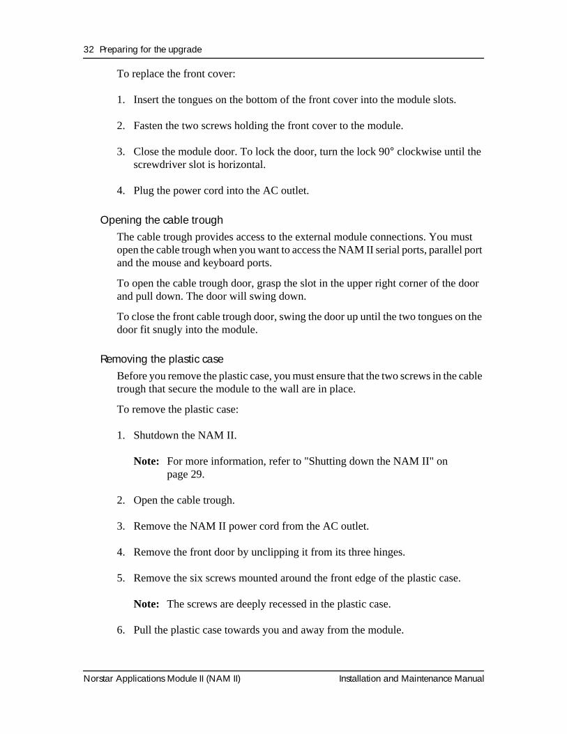
Figure 15 Removing the plastic case
To replace the plastic enclosure:
1. Place the plastic enclosure on the module and fasten its six screws to the module.
2. Replace the door by clipping it to its hinges.
3. Plug the power cord into the AC outlet.
4. Close the cable trough door.

34 Preparing for the upgrade
Norstar Applications Module II (NAM II) Installation and Maintenance Manual
Installation and Maintenance Manual Norstar Applications Module II (NAM II)
OverviewThe clock/calendar battery is responsible for keeping BIOS information current if the power to the module goes down. The BIOS contains information such as the unique serial number of the NAM II system. The battery must be replaced with a 3 V, 170 mAh, lithium coin cell such as a Sanyo CR2032.
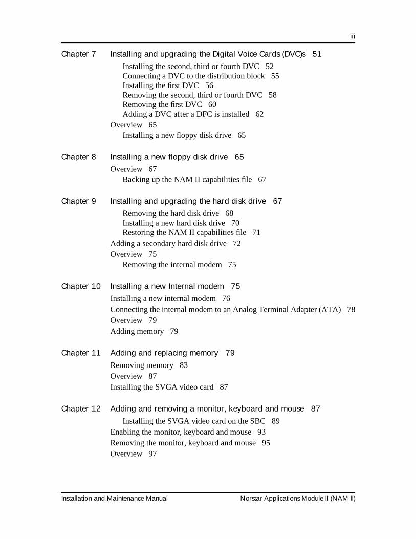
Removing and replacing the batteryTo remove the battery:
1. Shutdown the NAM II. For more information, refer to "Shutting down the NAM II" on page 29.
2. Remove the NAM II power cord from the AC outlet.
3. Ground yourself by attaching one end of the grounding strap to your wrist and the other end to a grounded metal surface.
4. Remove the front cover. Refer to "Accessing the inside of the NAM II" on page 30.
5. Remove any expansion bus cards that interfere with access to the battery.
6. Using your finger, gently lift the metal clamp that is holding the battery in the socket. The socket is located on the SBC.
7. For the location of the battery, refer to "Removing the battery" on page 36.
8. If the battery doesn’t immediately fall out of the socket, gently wiggle the SBC. This will cause the battery to drop out of the socket into your hand.
Installing the clock/calendar battery 5
WARNING
If you do not replace the battery with a 3 V, 170 mAh, lithium coin cell battery, there is a danger of explosion.
This document was created with FrameBuilder 4.0.4
36 Installing the clock/calendar battery
Norstar Applications Module II (NAM II) Installation and Maintenance Manual
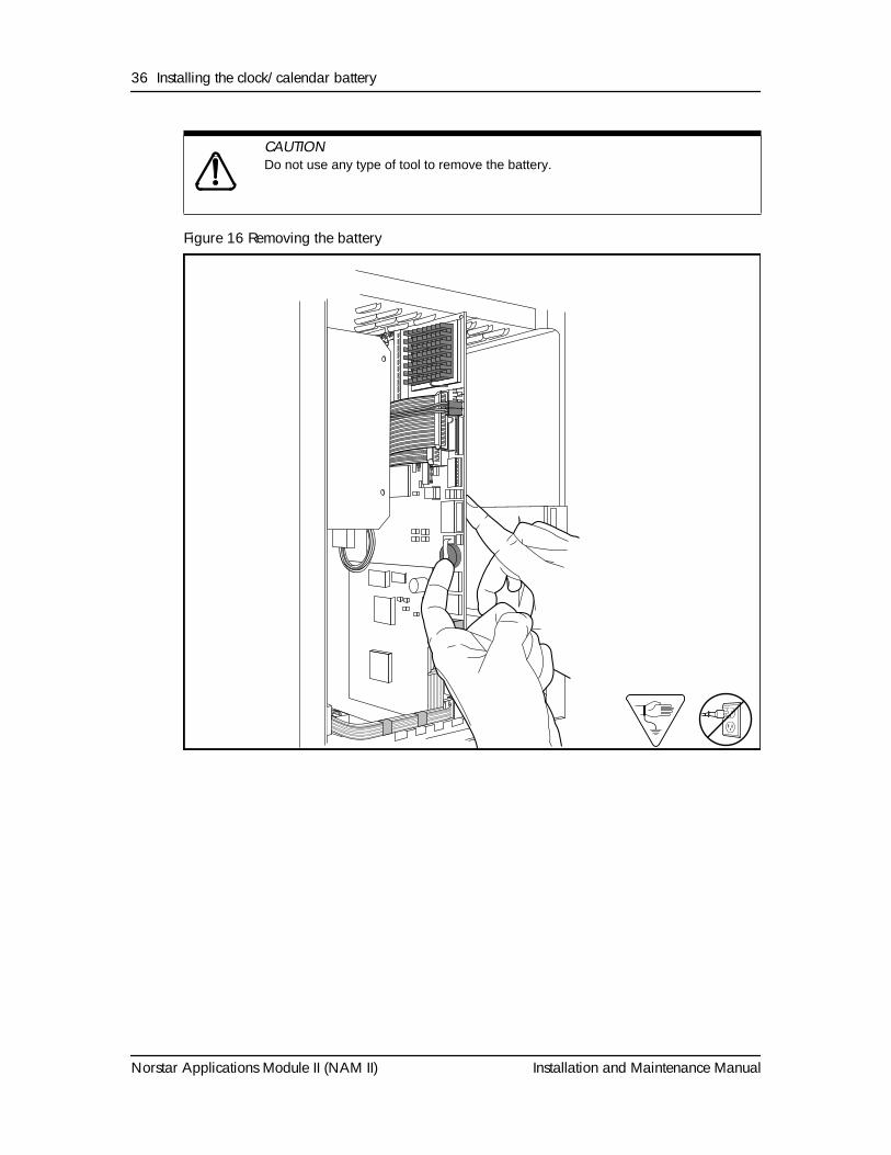
Figure 16 Removing the battery
CAUTION
Do not use any type of tool to remove the battery.2) Battery View & Hands 1.6
Installing the clock/calendar battery 37
Installation and Maintenance Manual Norstar Applications Module II (NAM II)
To install a new battery:
1. Slide the battery at a 45-degree angle under the metal clip until the battery snaps into the socket. Ensure the battery is completely seated in the socket. The positive (+) side of the battery faces upward.
2. Replace any expansion bus cards that were removed.
3. Replace the front cover.
4. Close the module door. To lock the door, turn the lock 90° clockwise until the screwdriver slot is horizontal.
5. Plug the power cord into the AC outlet.
WARNING
There is a danger of explosion if the battery is incorrectly replaced. You must replace the battery with a 3 V, 170 mAh, lithium coin cell battery.
38 Installing the clock/calendar battery
Norstar Applications Module II (NAM II) Installation and Maintenance Manual
Installation and Maintenance Manual Norstar Applications Module II (NAM II)
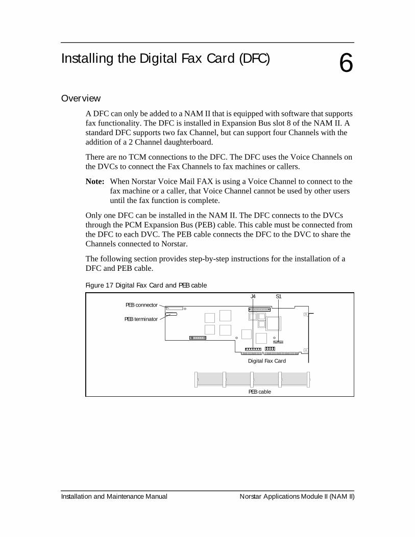
OverviewA DFC can only be added to a NAM II that is equipped with software that supports fax functionality. The DFC is installed in Expansion Bus slot 8 of the NAM II. A standard DFC supports two fax Channel, but can support four Channels with the addition of a 2 Channel daughterboard.
There are no TCM connections to the DFC. The DFC uses the Voice Channels on the DVCs to connect the Fax Channels to fax machines or callers.
Note: When Norstar Voice Mail FAX is using a Voice Channel to connect to the fax machine or a caller, that Voice Channel cannot be used by other users until the fax function is complete.
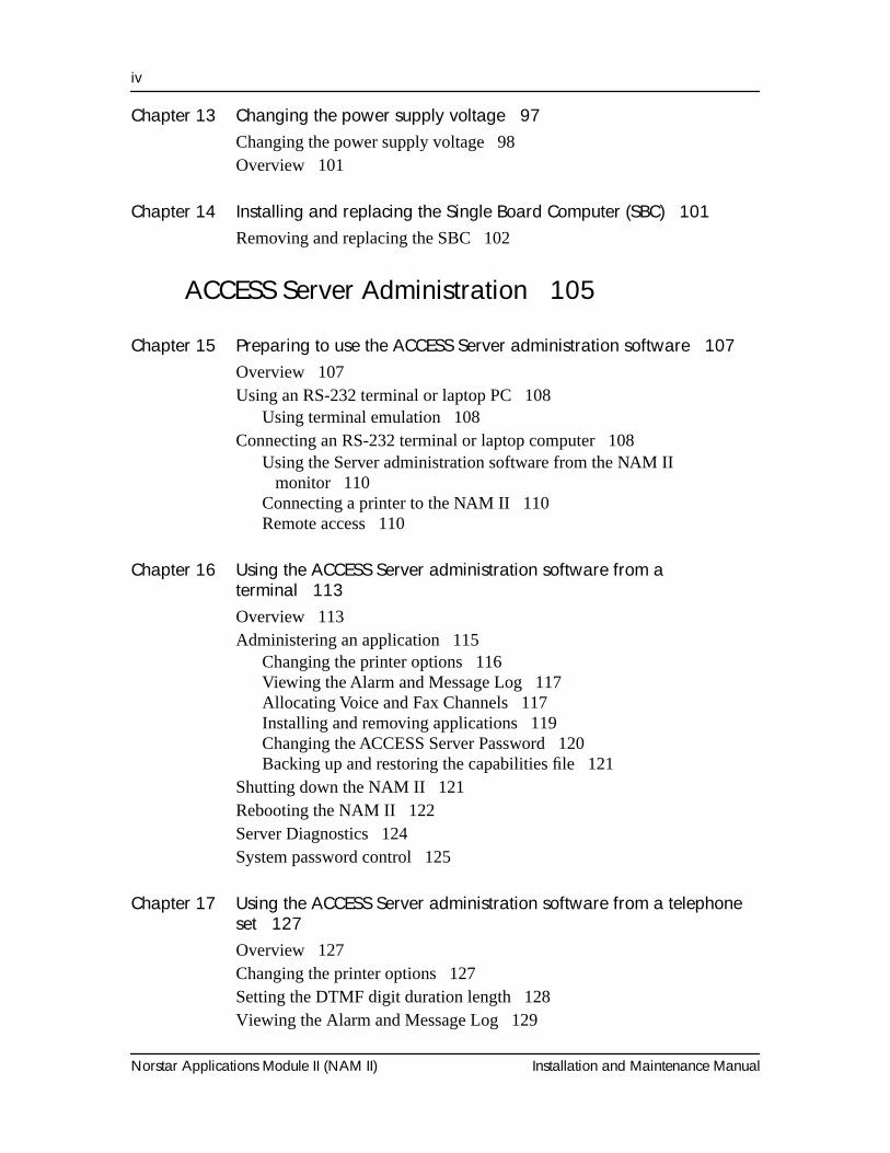
Only one DFC can be installed in the NAM II. The DFC connects to the DVCs through the PCM Expansion Bus (PEB) cable. This cable must be connected from the DFC to each DVC. The PEB cable connects the DFC to the DVC to share the Channels connected to Norstar.
The following section provides step-by-step instructions for the installation of a DFC and PEB cable.
Figure 17 Digital Fax Card and PEB cable
Installing the Digital Fax Card (DFC) 6
PEB connector
PEB terminator
Digital Fax Card
PEB cable
J4 S1
....... ........
40 Installing the Digital Fax Card (DFC)
Norstar Applications Module II (NAM II) Installation and Maintenance Manual
PrecautionsBefore installing or upgrading a DFC, you MUST take the following precautions:
• Unplug the NAM II power cord. The NAM II power supply contains high voltage. If you do not unplug the power cord you may severely injure yourself. Also, if cards are installed or removed from the NAM II before the power cord is unplugged, the cards and/or the NAM II may be damaged.
• Wear a ground strap. Static electricity can damage the components on the cards and the NAM II. Always wear a properly grounded antistatic strap while handling the DFC, DVC or any other component of the NAM II.
Installing the DFC
1. Shutdown the NAM II. For more information, refer to "Shutting down the NAM II" on page 29.
2. Remove the NAM II power cord from the AC outlet.
3. Open the front cover of the NAM II. Refer to "Accessing the inside of the NAM II" on page 30.
4. Ground yourself by attaching one end of the grounding strap to your wrist and the other end to a grounded metal surface.
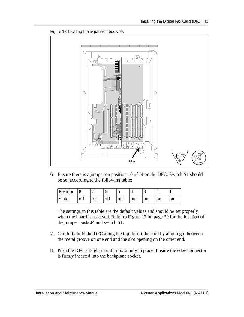
5. Locate slot 8 on the expansion bus. Remove the slot cover screw and the metal slot cover from the slot.
Installing the Digital Fax Card (DFC) 41
Installation and Maintenance Manual Norstar Applications Module II (NAM II)
Figure 18 Locating the expansion bus slots
6. Ensure there is a jumper on position 10 of J4 on the DFC. Switch S1 should be set according to the following table:
The settings in this table are the default values and should be set properly when the board is received. Refer to Figure 17 on page 39 for the location of the jumper posts J4 and switch S1.
7. Carefully hold the DFC along the top. Insert the card by aligning it between the metal groove on one end and the slot opening on the other end.
8. Push the DFC straight in until it is snugly in place. Ensure the edge connector is firmly inserted into the backplane socket.
Position 8 7 6 5 4 3 2 1
State off on off off on on on on
1) Front View 1.6
DFC
42 Installing the Digital Fax Card (DFC)
Norstar Applications Module II (NAM II) Installation and Maintenance Manual
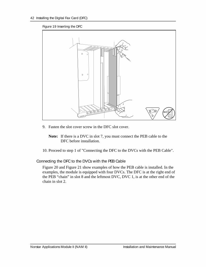
Figure 19 Inserting the DFC
9. Fasten the slot cover screw in the DFC slot cover.
Note: If there is a DVC in slot 7, you must connect the PEB cable to the DFC before installation.
10. Proceed to step 1 of "Connecting the DFC to the DVCs with the PEB Cable".
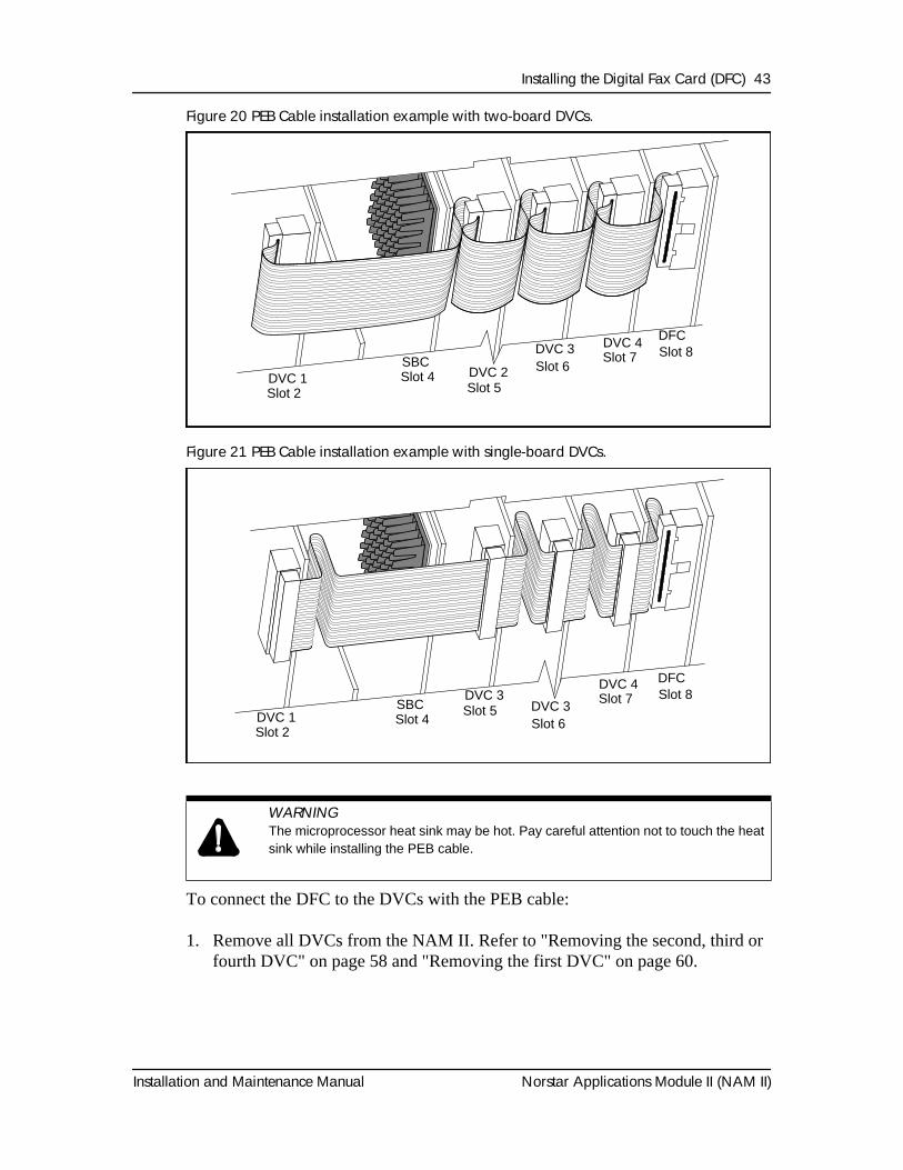
Connecting the DFC to the DVCs with the PEB CableFigure 20 and Figure 21 show examples of how the PEB cable is installed. In the examples, the module is equipped with four DVCs. The DFC is at the right end of the PEB “chain” in slot 8 and the leftmost DVC, DVC 1, is at the other end of the chain in slot 2.
Install Fax Card 1.5
Installing the Digital Fax Card (DFC) 43
Installation and Maintenance Manual Norstar Applications Module II (NAM II)
Figure 20 PEB Cable installation example with two-board DVCs.
Figure 21 PEB Cable installation example with single-board DVCs.
To connect the DFC to the DVCs with the PEB cable:
1. Remove all DVCs from the NAM II. Refer to "Removing the second, third or fourth DVC" on page 58 and "Removing the first DVC" on page 60.
WARNING
The microprocessor heat sink may be hot. Pay careful attention not to touch the heat sink while installing the PEB cable.
PEB Cable Install Ex. 1.5
DVC 1 DVC 2
DVC 3 DVC 4 DFC
Slot 2 Slot 5
Slot 6Slot 7 Slot 8
SBCSlot 4
PEB Cable Connection 2.6 epsPEB Cable Connection 2.7 eps
DVC 1
DVC 3DVC 3
DVC 4 DFC
Slot 2
Slot 5Slot 6
Slot 7 Slot 8SBCSlot 4
44 Installing the Digital Fax Card (DFC)
Norstar Applications Module II (NAM II) Installation and Maintenance Manual
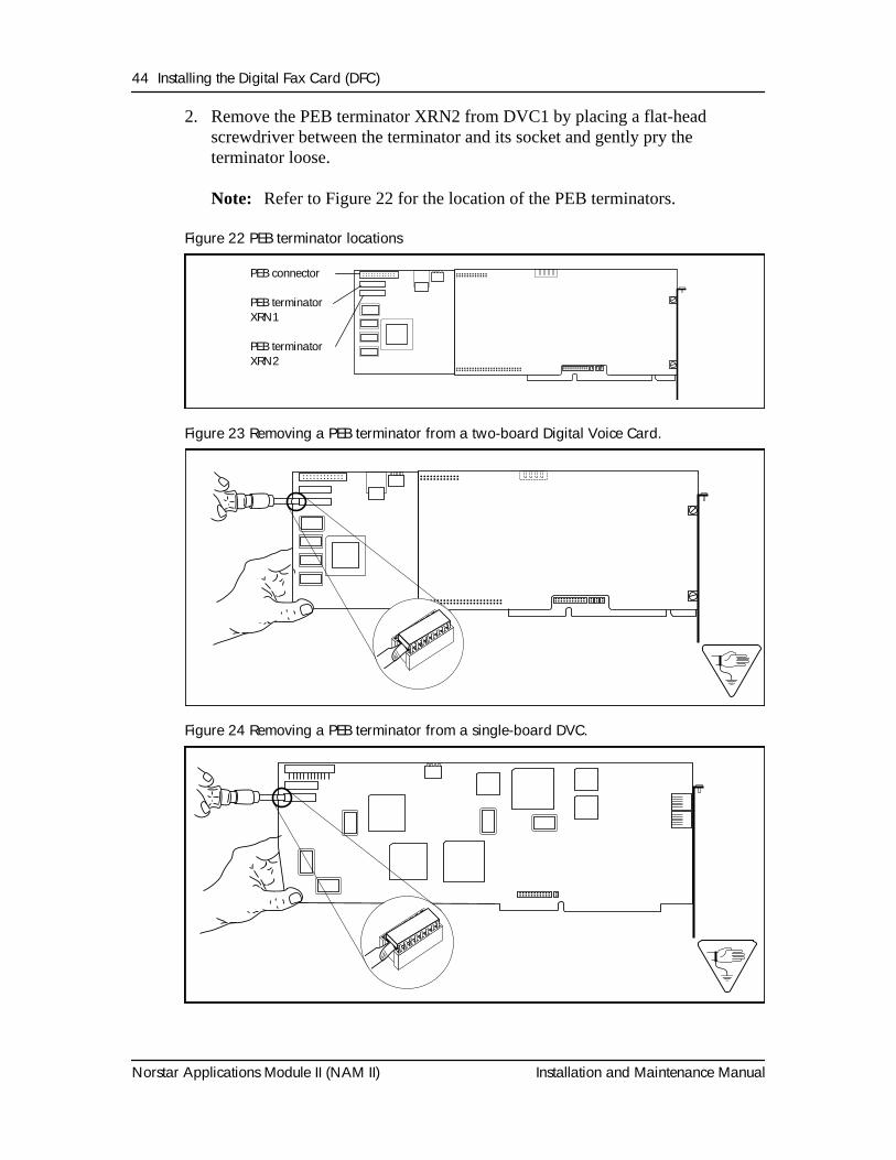
2. Remove the PEB terminator XRN2 from DVC1 by placing a flat-head screwdriver between the terminator and its socket and gently pry the terminator loose.
Note: Refer to Figure 22 for the location of the PEB terminators.
Figure 22 PEB terminator locations
Figure 23 Removing a PEB terminator from a two-board Digital Voice Card.
Figure 24 Removing a PEB terminator from a single-board DVC.
PEB connector
PEB terminatorXRN1
PEB terminatorXRN2
Installing the Digital Fax Card (DFC) 45
Installation and Maintenance Manual Norstar Applications Module II (NAM II)
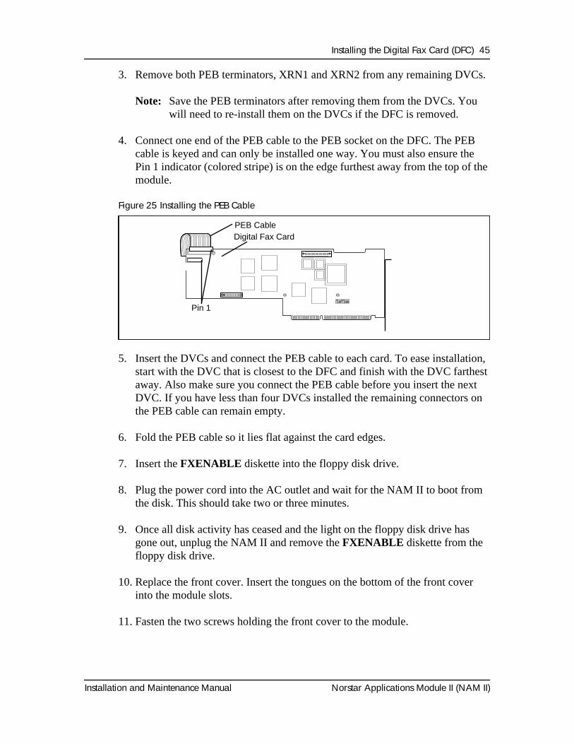
3. Remove both PEB terminators, XRN1 and XRN2 from any remaining DVCs.
Note: Save the PEB terminators after removing them from the DVCs. You will need to re-install them on the DVCs if the DFC is removed.
4. Connect one end of the PEB cable to the PEB socket on the DFC. The PEB cable is keyed and can only be installed one way. You must also ensure the Pin 1 indicator (colored stripe) is on the edge furthest away from the top of the module.
Figure 25 Installing the PEB Cable
5. Insert the DVCs and connect the PEB cable to each card. To ease installation, start with the DVC that is closest to the DFC and finish with the DVC farthest away. Also make sure you connect the PEB cable before you insert the next DVC. If you have less than four DVCs installed the remaining connectors on the PEB cable can remain empty.
6. Fold the PEB cable so it lies flat against the card edges.
7. Insert the FXENABLE diskette into the floppy disk drive.
8. Plug the power cord into the AC outlet and wait for the NAM II to boot from the disk. This should take two or three minutes.
9. Once all disk activity has ceased and the light on the floppy disk drive has gone out, unplug the NAM II and remove the FXENABLE diskette from the floppy disk drive.
10. Replace the front cover. Insert the tongues on the bottom of the front cover into the module slots.
11. Fasten the two screws holding the front cover to the module.
Pin 1
Digital Fax CardPEB Cable
46 Installing the Digital Fax Card (DFC)
Norstar Applications Module II (NAM II) Installation and Maintenance Manual
12. Close the module door. To lock the door, turn the lock 90° clockwise until the screwdriver slot is horizontal.
13. Plug the power cord into the AC outlet.
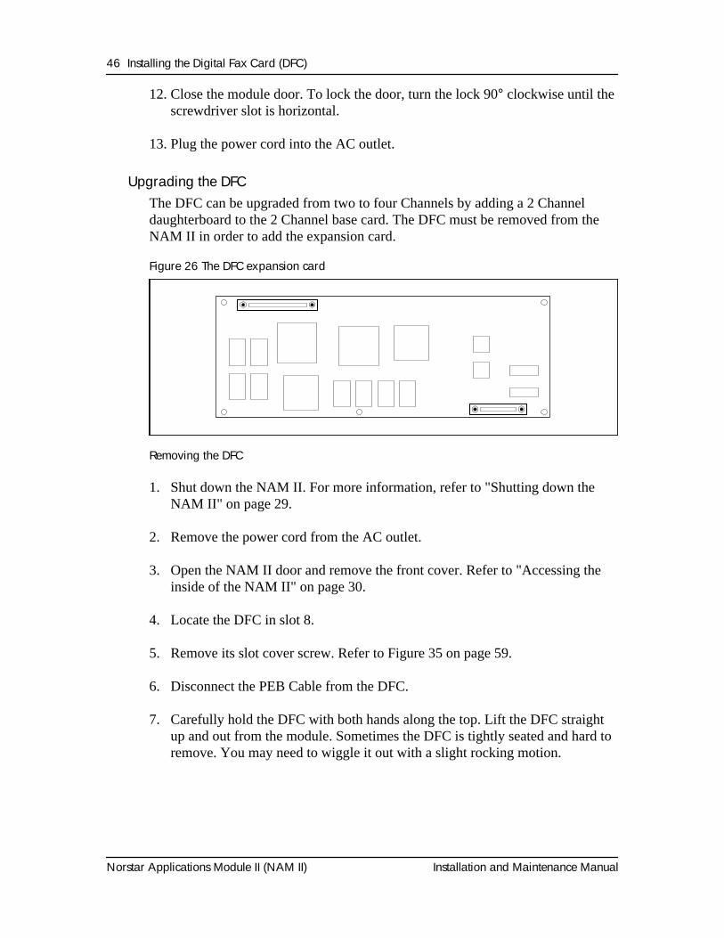
Upgrading the DFCThe DFC can be upgraded from two to four Channels by adding a 2 Channel daughterboard to the 2 Channel base card. The DFC must be removed from the NAM II in order to add the expansion card.
Figure 26 The DFC expansion card
Removing the DFC
1. Shut down the NAM II. For more information, refer to "Shutting down the NAM II" on page 29.
2. Remove the power cord from the AC outlet.
3. Open the NAM II door and remove the front cover. Refer to "Accessing the inside of the NAM II" on page 30.
4. Locate the DFC in slot 8.
5. Remove its slot cover screw. Refer to Figure 35 on page 59.
6. Disconnect the PEB Cable from the DFC.
7. Carefully hold the DFC with both hands along the top. Lift the DFC straight up and out from the module. Sometimes the DFC is tightly seated and hard to remove. You may need to wiggle it out with a slight rocking motion.
Installing the Digital Fax Card (DFC) 47
Installation and Maintenance Manual Norstar Applications Module II (NAM II)
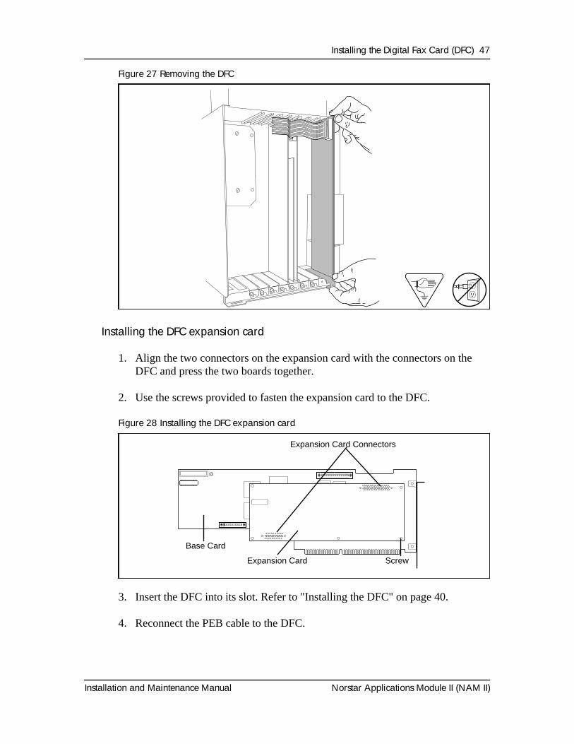
Figure 27 Removing the DFC
Installing the DFC expansion card
1. Align the two connectors on the expansion card with the connectors on the DFC and press the two boards together.
2. Use the screws provided to fasten the expansion card to the DFC.
Figure 28 Installing the DFC expansion card
3. Insert the DFC into its slot. Refer to "Installing the DFC" on page 40.
4. Reconnect the PEB cable to the DFC.
Install Fax Card 1.5
Expansion Card Connectors
Base Card
Expansion Card Screw
48 Installing the Digital Fax Card (DFC)
Norstar Applications Module II (NAM II) Installation and Maintenance Manual
5. Replace the front cover. Insert the tongues on the bottom of the front cover into the module slots.
6. Fasten the two screws holding the front cover to the module.
7. Close the module door. To lock the door, turn the lock 90° clockwise until the screwdriver slot is horizontal.
8. Plug the NAM II power cord into the AC outlet.
The additional two fax Channels are automatically enabled and ready to be used.
Removing fax functionality from the SystemThese steps are to be used only if you are removing the DFC and fax functionality from a NAM II that is equipped with Norstar Voice Mail. If you are replacing the DFC or upgrading the DFC, refer to "Installing the DFC" on page 40 or "Upgrading the DFC" on page 46.
WARNING
The microprocessor heat sink may be hot. Pay careful attention not to touch the heat sink when installing the PEB cable.
Installing the Digital Fax Card (DFC) 49
Installation and Maintenance Manual Norstar Applications Module II (NAM II)
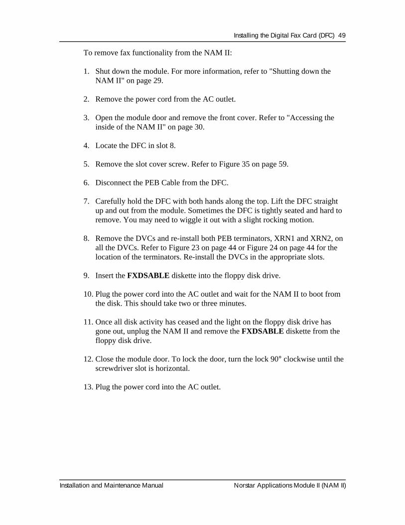
To remove fax functionality from the NAM II:
1. Shut down the module. For more information, refer to "Shutting down the NAM II" on page 29.
2. Remove the power cord from the AC outlet.
3. Open the module door and remove the front cover. Refer to "Accessing the inside of the NAM II" on page 30.
4. Locate the DFC in slot 8.
5. Remove the slot cover screw. Refer to Figure 35 on page 59.
6. Disconnect the PEB Cable from the DFC.
7. Carefully hold the DFC with both hands along the top. Lift the DFC straight up and out from the module. Sometimes the DFC is tightly seated and hard to remove. You may need to wiggle it out with a slight rocking motion.
8. Remove the DVCs and re-install both PEB terminators, XRN1 and XRN2, on all the DVCs. Refer to Figure 23 on page 44 or Figure 24 on page 44 for the location of the terminators. Re-install the DVCs in the appropriate slots.
9. Insert the FXDSABLE diskette into the floppy disk drive.
10. Plug the power cord into the AC outlet and wait for the NAM II to boot from the disk. This should take two or three minutes.
11. Once all disk activity has ceased and the light on the floppy disk drive has gone out, unplug the NAM II and remove the FXDSABLE diskette from the floppy disk drive.
12. Close the module door. To lock the door, turn the lock 90° clockwise until the screwdriver slot is horizontal.
13. Plug the power cord into the AC outlet.
50 Installing the Digital Fax Card (DFC)
Norstar Applications Module II (NAM II) Installation and Maintenance Manual
Installation and Maintenance Manual Norstar Applications Module II (NAM II)
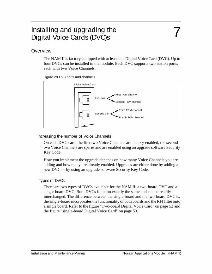
OverviewThe NAM II is factory equipped with at least one Digital Voice Card (DVC). Up to four DVCs can be installed in the module. Each DVC supports two station ports, each with two Voice Channels.
Figure 29 DVC ports and channels
Increasing the number of Voice ChannelsOn each DVC card, the first two Voice Channels are factory enabled, the second two Voice Channels are spares and are enabled using an upgrade software Security Key Code.
How you implement the upgrade depends on how many Voice Channels you are adding and how many are already enabled. Upgrades are either done by adding a new DVC or by using an upgrade software Security Key Code.
Types of DVCsThere are two types of DVCs available for the NAM II: a two-board DVC and a single-board DVC. Both DVCs function exactly the same and can be readily interchanged. The difference between the single-board and the two-board DVC is, the single-board incorporates the functionality of both boards and the RFI filter onto a single board. Refer to the figure "Two-board Digital Voice Card" on page 52 and the figure "single-board Digital Voice Card" on page 53.
Installing and upgrading the Digital Voice Cards (DVC)s 7
Digital Voice Card
First port
Second port
First TCM channel
Second TCM channel
Third TCM channel
Fourth TCM channel
52 Installing and upgrading the Digital Voice Cards (DVC)s
Norstar Applications Module II (NAM II) Installation and Maintenance Manual
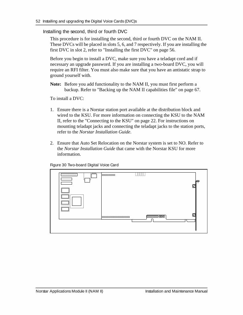
Installing the second, third or fourth DVC This procedure is for installing the second, third or fourth DVC on the NAM II. These DVCs will be placed in slots 5, 6, and 7 respectively. If you are installing the first DVC in slot 2, refer to "Installing the first DVC" on page 56.
Before you begin to install a DVC, make sure you have a teladapt cord and if necessary an upgrade password. If you are installing a two-board DVC, you will require an RFI filter. You must also make sure that you have an antistatic strap to ground yourself with.
Note: Before you add functionality to the NAM II, you must first perform a backup. Refer to "Backing up the NAM II capabilities file" on page 67.
To install a DVC:
1. Ensure there is a Norstar station port available at the distribution block and wired to the KSU. For more information on connecting the KSU to the NAM II, refer to the "Connecting to the KSU" on page 22. For instructions on mounting teladapt jacks and connecting the teladapt jacks to the station ports, refer to the Norstar Installation Guide.
2. Ensure that Auto Set Relocation on the Norstar system is set to NO. Refer to the Norstar Installation Guide that came with the Norstar KSU for more information.
Figure 30 Two-board Digital Voice Card
Installing and upgrading the Digital Voice Cards (DVC)s 53
Installation and Maintenance Manual Norstar Applications Module II (NAM II)
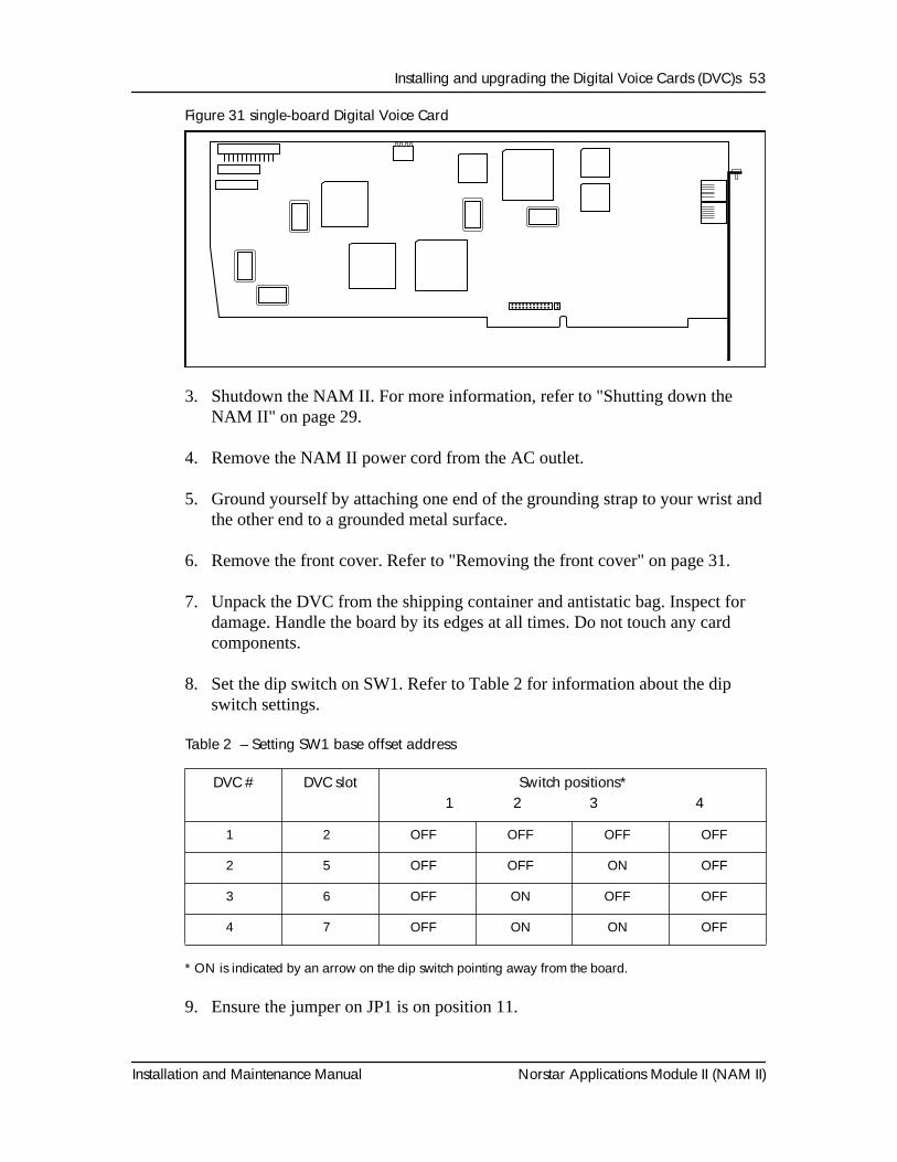
Figure 31 single-board Digital Voice Card
3. Shutdown the NAM II. For more information, refer to "Shutting down the NAM II" on page 29.
4. Remove the NAM II power cord from the AC outlet.
5. Ground yourself by attaching one end of the grounding strap to your wrist and the other end to a grounded metal surface.
6. Remove the front cover. Refer to "Removing the front cover" on page 31.
7. Unpack the DVC from the shipping container and antistatic bag. Inspect for damage. Handle the board by its edges at all times. Do not touch any card components.
8. Set the dip switch on SW1. Refer to Table 2 for information about the dip switch settings.
Table 2 – Setting SW1 base offset address
* ON is indicated by an arrow on the dip switch pointing away from the board.
9. Ensure the jumper on JP1 is on position 11.
DVC # DVC slot Switch positions* 1 2 3 4
1 2 OFF OFF OFF OFF
2 5 OFF OFF ON OFF
3 6 OFF ON OFF OFF
4 7 OFF ON ON OFF
54 Installing and upgrading the Digital Voice Cards (DVC)s
Norstar Applications Module II (NAM II) Installation and Maintenance Manual
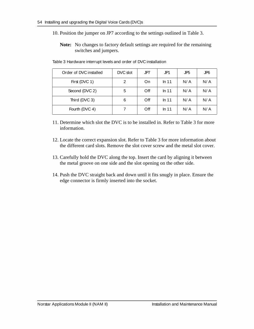
10. Position the jumper on JP7 according to the settings outlined in Table 3.
Note: No changes to factory default settings are required for the remaining switches and jumpers.
Table 3 Hardware interrupt levels and order of DVC installation
11. Determine which slot the DVC is to be installed in. Refer to Table 3 for more information.
12. Locate the correct expansion slot. Refer to Table 3 for more information about the different card slots. Remove the slot cover screw and the metal slot cover.
13. Carefully hold the DVC along the top. Insert the card by aligning it between the metal groove on one side and the slot opening on the other side.
14. Push the DVC straight back and down until it fits snugly in place. Ensure the edge connector is firmly inserted into the socket.
Order of DVC installed DVC slot JP7 JP1 JP5 JP6
First (DVC 1) 2 On In 11 N/A N/A
Second (DVC 2) 5 Off In 11 N/A N/A
Third (DVC 3) 6 Off In 11 N/A N/A
Fourth (DVC 4) 7 Off In 11 N/A N/A
Installing and upgrading the Digital Voice Cards (DVC)s 55
Installation and Maintenance Manual Norstar Applications Module II (NAM II)
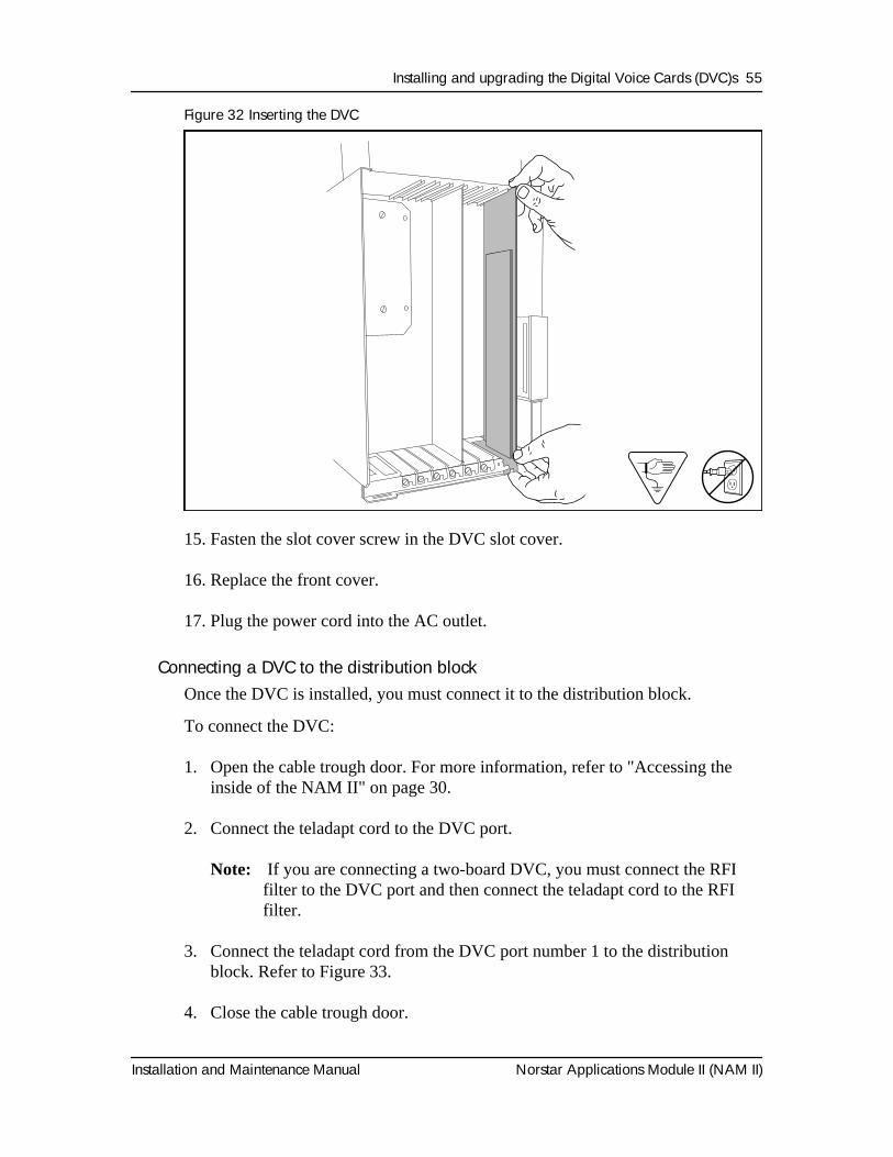
Figure 32 Inserting the DVC
15. Fasten the slot cover screw in the DVC slot cover.
16. Replace the front cover.
17. Plug the power cord into the AC outlet.
Connecting a DVC to the distribution blockOnce the DVC is installed, you must connect it to the distribution block.
To connect the DVC:
1. Open the cable trough door. For more information, refer to "Accessing the inside of the NAM II" on page 30.
2. Connect the teladapt cord to the DVC port.
Note: If you are connecting a two-board DVC, you must connect the RFI filter to the DVC port and then connect the teladapt cord to the RFI filter.
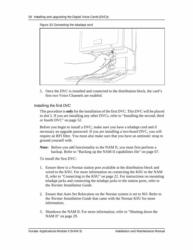
3. Connect the teladapt cord from the DVC port number 1 to the distribution block. Refer to Figure 33.
4. Close the cable trough door.
Install DVC Card 1.5
56 Installing and upgrading the Digital Voice Cards (DVC)s
Norstar Applications Module II (NAM II) Installation and Maintenance Manual
Figure 33 Connecting the teladapt cord
5. Once the DVC is installed and connected to the distribution block, the card’s first two Voice Channels are enabled.
Installing the first DVC This procedure is only for the installation of the first DVC. This DVC will be placed in slot 2. If you are installing any other DVCs, refer to "Installing the second, third or fourth DVC" on page 52.
Before you begin to install a DVC, make sure you have a teladapt cord and if necessary an upgrade password. If you are installing a two-board DVC, you will require an RFI filter. You must also make sure that you have an antistatic strap to ground yourself with.
Note: Before you add functionality to the NAM II, you must first perform a backup. Refer to "Backing up the NAM II capabilities file" on page 67.
To install the first DVC:
1. Ensure there is a Norstar station port available at the distribution block and wired to the KSU. For more information on connecting the KSU to the NAM II, refer to "Connecting to the KSU" on page 22. For instructions on mounting teladapt jacks and connecting the teladapt jacks to the station ports, refer to the Norstar Installation Guide.
2. Ensure that Auto Set Relocation on the Norstar system is set to NO. Refer to the Norstar Installation Guide that came with the Norstar KSU for more information.
3. Shutdown the NAM II. For more information, refer to "Shutting down the NAM II" on page 29.
Installing and upgrading the Digital Voice Cards (DVC)s 57
Installation and Maintenance Manual Norstar Applications Module II (NAM II)
4. Remove the NAM II power cord from the AC outlet.
5. Ground yourself by attaching one end of the grounding strap to your wrist and the other end to a grounded metal surface.
6. Remove the front cover. Refer to "Removing the front cover" on page 31.
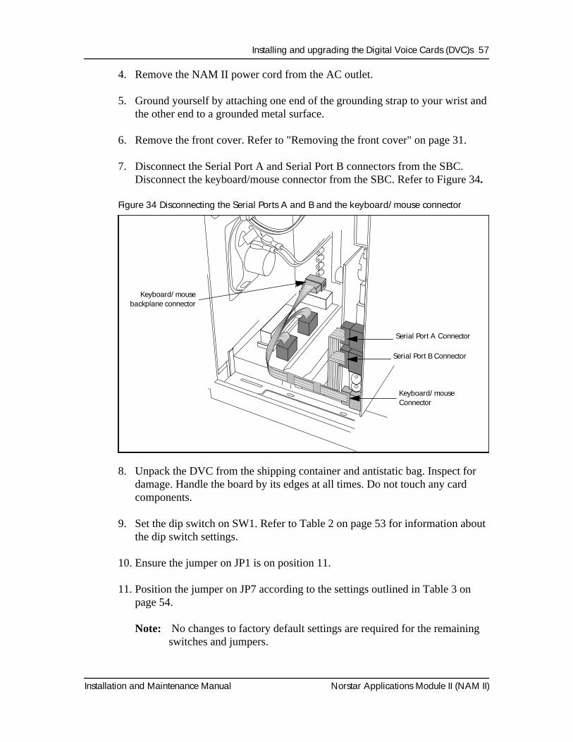
7. Disconnect the Serial Port A and Serial Port B connectors from the SBC. Disconnect the keyboard/mouse connector from the SBC. Refer to Figure 34.
Figure 34 Disconnecting the Serial Ports A and B and the keyboard/mouse connector
8. Unpack the DVC from the shipping container and antistatic bag. Inspect for damage. Handle the board by its edges at all times. Do not touch any card components.
9. Set the dip switch on SW1. Refer to Table 2 on page 53 for information about the dip switch settings.
10. Ensure the jumper on JP1 is on position 11.
11. Position the jumper on JP7 according to the settings outlined in Table 3 on page 54.
Note: No changes to factory default settings are required for the remaining switches and jumpers.
4) Lower Connections 1.6
Serial Port A Connector
Serial Port B Connector
Keyboard/mouseConnector
Keyboard/mousebackplane connector
58 Installing and upgrading the Digital Voice Cards (DVC)s
Norstar Applications Module II (NAM II) Installation and Maintenance Manual
12. Locate expansion slot 2. Refer to Table 3 on page 54 for more information about the different card slots. Remove the slot cover screw and the metal slot cover.
13. Gently push the large ribbon cables leading to the SBC flat against the backplane. This will allow for easier installation of the DVC.
14. Carefully hold the DVC along the top. Insert the card by aligning it between the metal groove on one side and the slot opening on the other side.
15. Push the DVC straight back and down until it fits snugly in place. Ensure the edge connector is firmly inserted into the socket.
16. Reconnect the Serial Port A and Serial Port B connectors to the SBC. Reconnect the keyboard/mouse connector to the SBC. Refer to Figure 34 for the location of the connectors.
Note: Ensure the keyboard/mouse ribbon cable is still connected to the backplane.
17. Fasten the slot cover screw in the DVC slot cover.
18. Replace the front cover.
19. Plug the power cord into the AC outlet.
Removing the second, third or fourth DVCThis procedure is for removing the second, third or fourth DVC from the NAM II. These DVCs will be located in slots 5, 6, and 7 respectively. If you are removing the first DVC from slot 2, refer to "Removing the first DVC" on page 60.
A DVC is removed when a failure is suspected or confirmed.
Note: If your system has Norstar Voice Mail installed, ensure the TCM loop connected to the DVC is not associated with the Norstar Voice Mail DN. If the TCM loop is associated with the Norstar Voice Mail DN, make sure you reconnect the loop back to another DVC.
To remove a DVC:
1. Shutdown the NAM II. For more information, refer to "Shutting down the NAM II" on page 29.
2. Remove the NAM II power cord from the AC outlet.
Installing and upgrading the Digital Voice Cards (DVC)s 59
Installation and Maintenance Manual Norstar Applications Module II (NAM II)
3. Ground yourself by attaching one end of the grounding strap to your wrist and the other end to a grounded metal surface.
4. Remove the front cover. Refer to "Removing the front cover" on page 31 for more information on accessing the module.
5. Locate the DVC and disconnect the teladapt cord.
Note: If you are removing a two-board DVC, you must also disconnect the RFI filter(s).
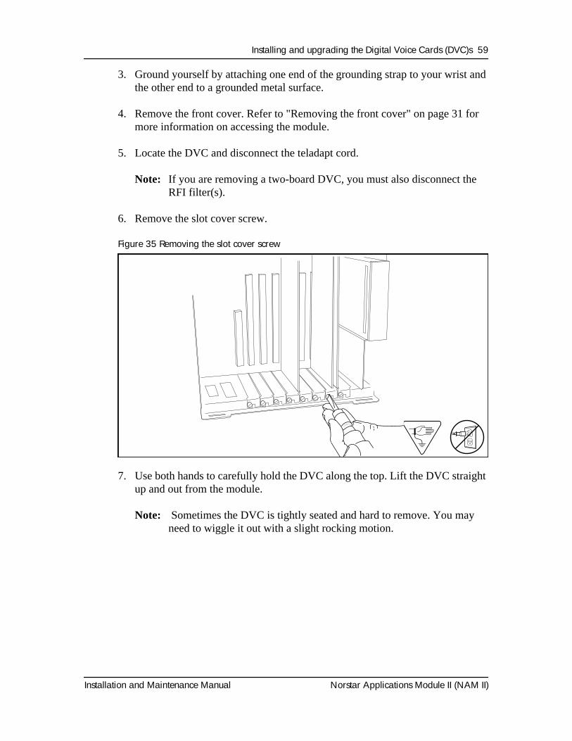
6. Remove the slot cover screw.
Figure 35 Removing the slot cover screw
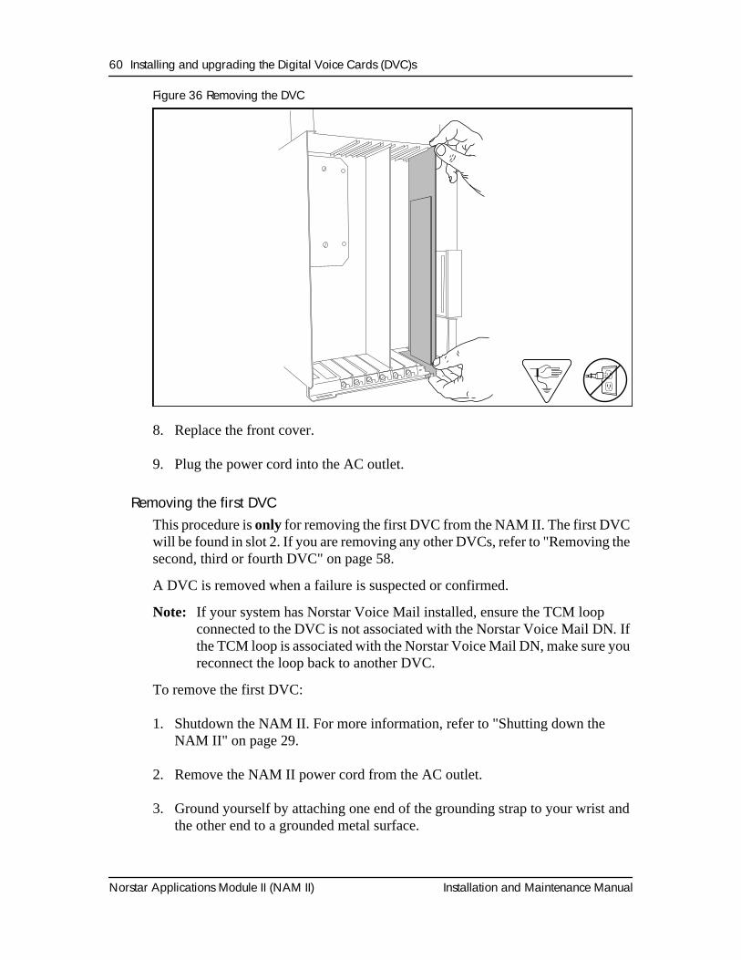
7. Use both hands to carefully hold the DVC along the top. Lift the DVC straight up and out from the module.
Note: Sometimes the DVC is tightly seated and hard to remove. You may need to wiggle it out with a slight rocking motion.
60 Installing and upgrading the Digital Voice Cards (DVC)s
Norstar Applications Module II (NAM II) Installation and Maintenance Manual
Figure 36 Removing the DVC
8. Replace the front cover.
9. Plug the power cord into the AC outlet.
Removing the first DVCThis procedure is only for removing the first DVC from the NAM II. The first DVC will be found in slot 2. If you are removing any other DVCs, refer to "Removing the second, third or fourth DVC" on page 58.
A DVC is removed when a failure is suspected or confirmed.
Note: If your system has Norstar Voice Mail installed, ensure the TCM loop connected to the DVC is not associated with the Norstar Voice Mail DN. If the TCM loop is associated with the Norstar Voice Mail DN, make sure you reconnect the loop back to another DVC.
To remove the first DVC:
1. Shutdown the NAM II. For more information, refer to "Shutting down the NAM II" on page 29.
2. Remove the NAM II power cord from the AC outlet.
3. Ground yourself by attaching one end of the grounding strap to your wrist and the other end to a grounded metal surface.
Install DVC Card 1.5
Installing and upgrading the Digital Voice Cards (DVC)s 61
Installation and Maintenance Manual Norstar Applications Module II (NAM II)
4. Remove the front cover. Refer to "Removing the plastic case" on page 32 earlier in this section for more information on accessing the module.
5. Disconnect the Serial Port A and Serial Port B connectors from the SBC. Disconnect the keyboard/mouse connector from the SBC. Refer to Figure 34 on page 57.
6. Locate the DVC in slot 2 and disconnect the teladapt cord.
Note: If you are removing a two-board DVC, you must also disconnect the RFI filter(s).
7. Remove the slot cover screw. Refer to Figure 35 on page 59.
8. Use both hands to carefully hold the DVC along the top. Lift the DVC straight up and out from the module. Sometimes the DVC is tightly seated and hard to remove. You may need to wiggle it out with a slight rocking motion.
9. Reconnect the Serial Port A and Serial Port B connectors to the SBC. Reconnect the keyboard/mouse connector to the SBC. Refer to Figure 34 on page 57 for the location of the connectors.
Note: Ensure the keyboard/mouse ribbon cable is still connected to the backplane.
10. Replace the front cover.
11. Plug the power cord into the AC outlet.
62 Installing and upgrading the Digital Voice Cards (DVC)s
Norstar Applications Module II (NAM II) Installation and Maintenance Manual
Adding a DVC after a DFC is installedThese steps are only for systems that have Norstar Voice Mail and Norstar Voice Mail FAX installed.
The installation of a DVC after a DFC is installed requires a few extra steps. These extra steps are required to remove PEB terminators and install the PEB cable.
To install a DVC:
1. Shutdown the NAM II. For more information, refer to "Shutting down the NAM II" on page 29.
2. Unplug the module from the AC outlet.
3. Ground yourself by attaching one end of the grounding strap to your wrist and the other end to a grounded metal surface.
4. Remove the front cover. Refer to "Removing the front cover" on page 31.
5. Open the module door and remove the front cover.
6. Set the switches and jumpers on the DVC you are adding. Settings for the switches and jumpers are listed in, "Installing the second, third or fourth DVC" on page 52.
7. Remove the XRN1 and XRN2 terminators from the DVC you are installing. For the location of the terminators, refer to Figure 23 on page 44.
8. Disconnect the PEB cable from the DVCs already installed in the NAM II.
9. Remove the slot cover screw and the metal slot cover from the slot you are adding the new DVC to.
Note: DVC slot assignment is listed in Table 3 on page 54.
10. Carefully hold the DVC along the top. Insert the card by aligning it between the metal groove on one side and the slot opening on the other side.
WARNING
The microprocessor heat sink may be hot. Pay careful attention not to touch the heat sink while installing the PEB cable.
Installing and upgrading the Digital Voice Cards (DVC)s 63
Installation and Maintenance Manual Norstar Applications Module II (NAM II)
11. Push the DVC straight down until it fits snugly in place. Ensure the edge connector is firmly inserted into the backplane socket, refer to Figure 32 on page 55.
12. Fasten the slot cover screw in the DVC slot cover.
13. Connect the PEB cable to each DVC in the NAM II.
14. Fold the PEB cable so it lies flat against the card edges.
15. Replace the front cover and close the module door.
16. Plug the power cord into the AC outlet.
The DVC must be connected to the distribution block. Refer to "Connecting a DVC to the distribution block" on page 55.

64 Installing and upgrading the Digital Voice Cards (DVC)s
Norstar Applications Module II (NAM II) Installation and Maintenance Manual
Installation and Maintenance Manual Norstar Applications Module II (NAM II)
OverviewWhen you are replacing the floppy disk drive, you must remove the front cover and the plastic case enclosing the NAM II. The screws holding the floppy disk drive in place are only accessible from the outside edge of the module.
Installing a new floppy disk driveTo remove the floppy disk drive:
1. Shutdown the module. For more information, refer to "Shutting down the NAM II" on page 29.
2. Remove the NAM II power cord from the AC outlet.
3. Remove the front cover and plastic case. For more information about removing the front cover and plastic case, refer to "Accessing the inside of the NAM II" on page 30.
4. Ground yourself by attaching one end of the grounding strap to your wrist and the other end to a grounded metal surface.
5. Loosen, but do not remove the two screws that fasten the floppy disk drive to the module wall. Slowly lift the floppy drive up and away from the module wall.
6. Disconnect the power supply wiring and ribbon cable from the floppy disk drive.
Installing a new floppy disk drive 8
CAUTION
Only pull or push on the plastic connectors. Do not pull on the cable. If the connector is tight, wiggle it loose with a slight rocking motion.
This document was created with FrameBuilder 4.0.4
66 Installing a new floppy disk drive
Norstar Applications Module II (NAM II) Installation and Maintenance Manual
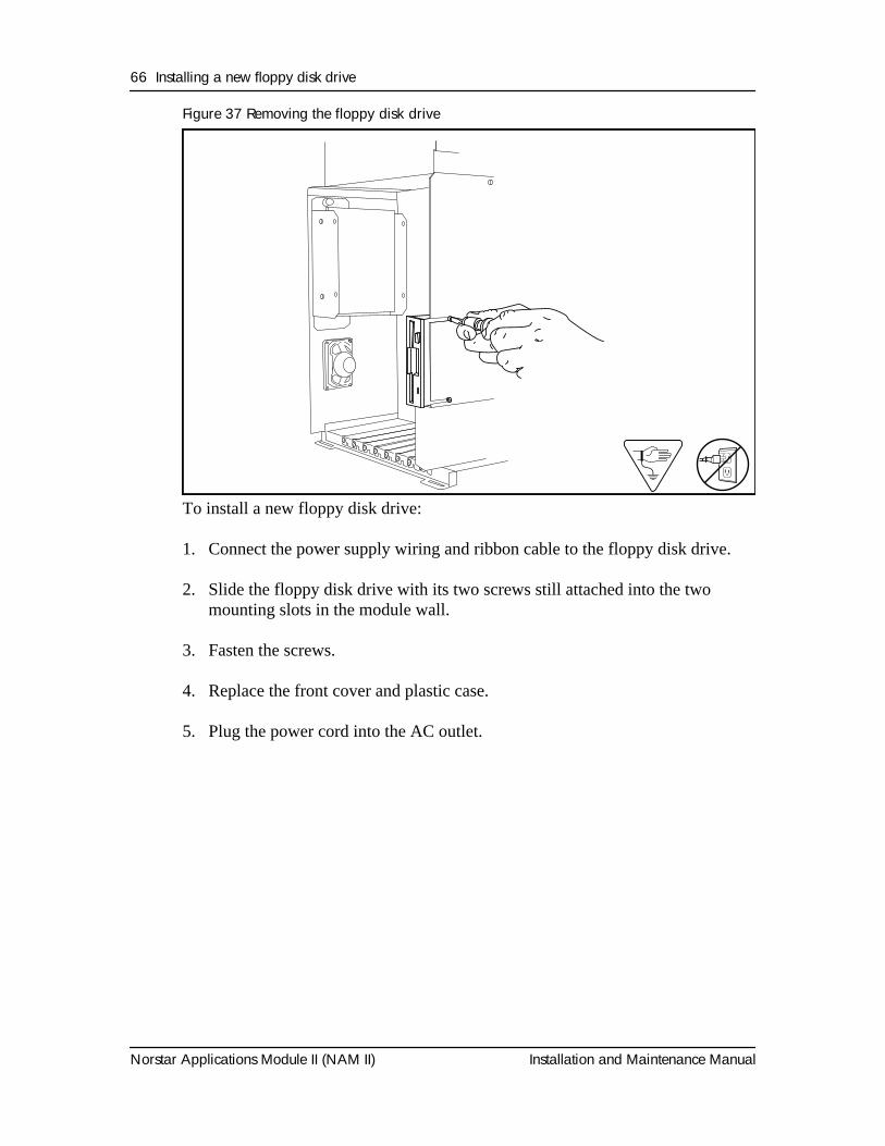
Figure 37 Removing the floppy disk drive
To install a new floppy disk drive:
1. Connect the power supply wiring and ribbon cable to the floppy disk drive.
2. Slide the floppy disk drive with its two screws still attached into the two mounting slots in the module wall.
3. Fasten the screws.
4. Replace the front cover and plastic case.
5. Plug the power cord into the AC outlet.
Installation and Maintenance Manual Norstar Applications Module II (NAM II)
OverviewThe NAM II includes one factory installed hard disk drive. This hard disk drive can be replaced if a problem is diagnosed.
When you replace a hard disk, you must backup and restore the NAM II capabilities file.
Table 4 Hard disk drive summary
*Approximate - the amount of message storage time depends on what applications are installed on the NAM II hard disk drive.
Backing up the NAM II capabilities fileYou must back up the capabilities file SEKUR. The SEKUR file contains all upgrade and capability information about your system, including the number of voice channels and any upgrades to your system. The SEKUR file must be restored if a hard disk failure occurs.
If this file is lost and your hard disk drive fails, all upgrades made to your system will be lost.
Note: Before you begin, ensure you have a blank high density formatted 1.44 MB 3.5" floppy disk. Label the disk SEKUR/Capabilities File.
To back up the NAM II capabilities file:
Installing and upgrading the hard disk drive 9
Hard Disk Drive Hard disk size(minimum)
Hours of message storage*(minimum)
Primary 1.2 GB 70
Secondary 1.2 GB 77
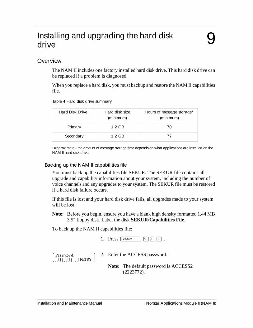
1. Press
ƒ ·⁄fi
.
2. Enter the ACCESS password.
Note:
The default password is ACCESS2 (2223772).
Password:∫∫∫∫∫∫∫∫ ∫∫RETRY
68 Installing and upgrading the hard disk drive
Norstar Applications Module II (NAM II) Installation and Maintenance Manual
Once you have backed up the NAM II capabilities file, make sure you store the floppy disks in a safe place.
Removing the hard disk drive
1. Shutdown the NAM II. For more information, refer to "Shutting down the NAM II" on page 29.
2. Remove the NAM II power cord from the AC outlet.
3. Ground yourself by attaching one end of the grounding strap to your wrist and the other end to a grounded metal surface.
4. Remove the front cover. Refer to "Accessing the inside of the NAM II" on page 30.
5. Disconnect the power supply wiring and ribbon cable from the hard disk drive. If another hard disk drive is installed, its wiring and cabling must also be disconnected.
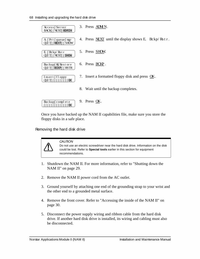
3. Press ADMIN
.
4. Press
NEXT
until the display shows
E. Bckp/Rstr
.
5. Press
SHOW
.
6. Press
BCKP
.
7. Insert a formatted floppy disk and press
OK
.
8. Wait until the backup completes.
9. Press
OK
.
CAUTION
Do not use an electric screwdriver near the hard disk drive. Information on the disk could be lost. Refer to
Special tools
earlier in this section for equipment recommendations.
Access∫ServerBACK∫∫NEXT∫
ADMIN
A.∫Prt∫queue∫mgrQUIT∫∫
NEXT
∫∫SHOW
E.∫Bckp/RstrQUIT∫∫NEXT∫∫
SHOW
Backup∫&∫RestoreQUIT∫∫
BCKP
∫∫RSTR
Insert∫floppyQUIT∫∫∫∫∫∫∫∫∫∫
OK
Backup∫complete∫∫∫∫∫∫∫∫∫∫∫∫∫∫
OK
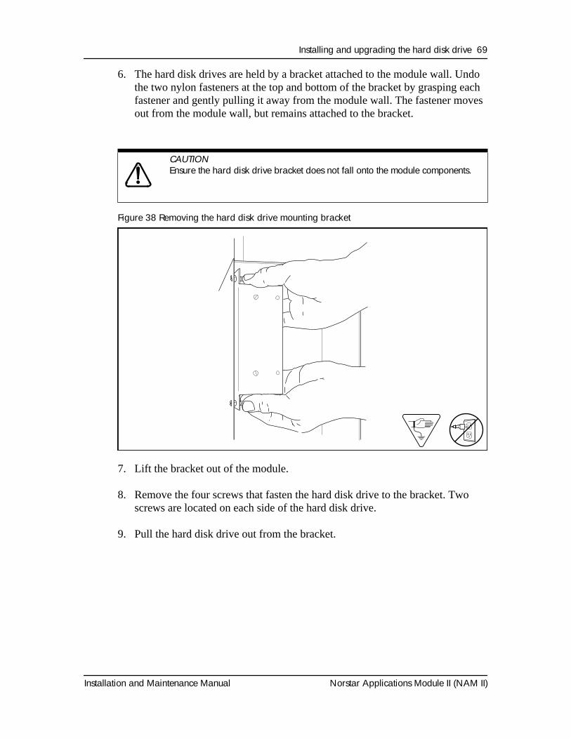
Installing and upgrading the hard disk drive 69
Installation and Maintenance Manual Norstar Applications Module II (NAM II)
6. The hard disk drives are held by a bracket attached to the module wall. Undo the two nylon fasteners at the top and bottom of the bracket by grasping each fastener and gently pulling it away from the module wall. The fastener moves out from the module wall, but remains attached to the bracket.
Figure 38 Removing the hard disk drive mounting bracket
7. Lift the bracket out of the module.
8. Remove the four screws that fasten the hard disk drive to the bracket. Two screws are located on each side of the hard disk drive.
9. Pull the hard disk drive out from the bracket.
CAUTION
Ensure the hard disk drive bracket does not fall onto the module components.
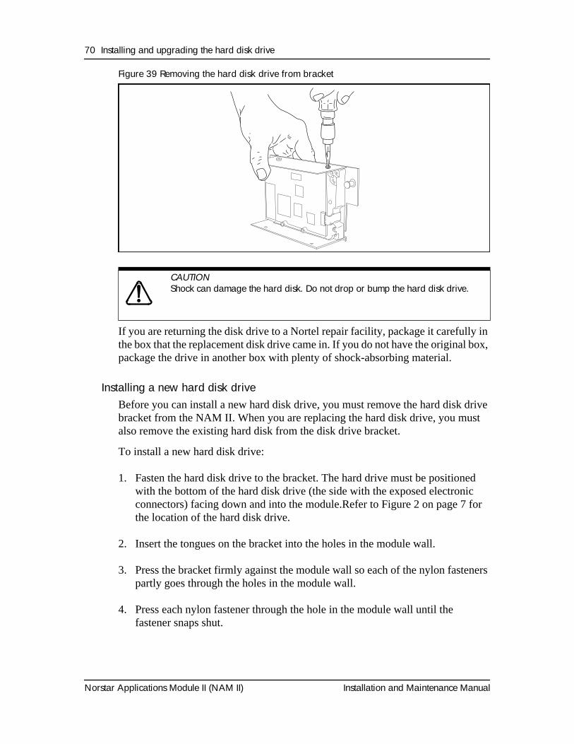
70 Installing and upgrading the hard disk drive
Norstar Applications Module II (NAM II) Installation and Maintenance Manual
Figure 39 Removing the hard disk drive from bracket
If you are returning the disk drive to a Nortel repair facility, package it carefully in the box that the replacement disk drive came in. If you do not have the original box, package the drive in another box with plenty of shock-absorbing material.
Installing a new hard disk driveBefore you can install a new hard disk drive, you must remove the hard disk drive bracket from the NAM II. When you are replacing the hard disk drive, you must also remove the existing hard disk from the disk drive bracket.
To install a new hard disk drive:
1. Fasten the hard disk drive to the bracket. The hard drive must be positioned with the bottom of the hard disk drive (the side with the exposed electronic connectors) facing down and into the module.Refer to Figure 2 on page 7 for the location of the hard disk drive.
2. Insert the tongues on the bracket into the holes in the module wall.
3. Press the bracket firmly against the module wall so each of the nylon fasteners partly goes through the holes in the module wall.
4. Press each nylon fastener through the hole in the module wall until the fastener snaps shut.
CAUTION
Shock can damage the hard disk. Do not drop or bump the hard disk drive.
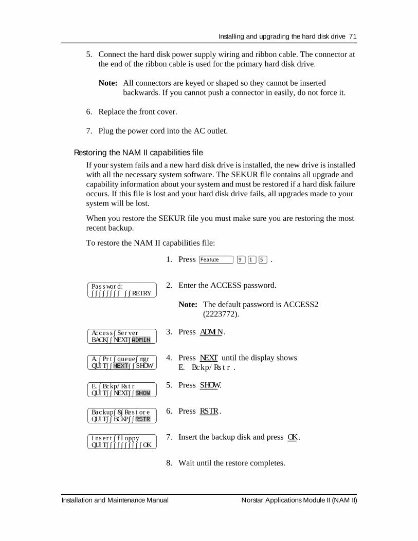
Installing and upgrading the hard disk drive 71
Installation and Maintenance Manual Norstar Applications Module II (NAM II)
5. Connect the hard disk power supply wiring and ribbon cable. The connector at the end of the ribbon cable is used for the primary hard disk drive.
Note: All connectors are keyed or shaped so they cannot be inserted backwards. If you cannot push a connector in easily, do not force it.
6. Replace the front cover.
7. Plug the power cord into the AC outlet.
Restoring the NAM II capabilities fileIf your system fails and a new hard disk drive is installed, the new drive is installed with all the necessary system software. The SEKUR file contains all upgrade and capability information about your system and must be restored if a hard disk failure occurs. If this file is lost and your hard disk drive fails, all upgrades made to your system will be lost.
When you restore the SEKUR file you must make sure you are restoring the most recent backup.
To restore the NAM II capabilities file:
1. Press
ƒ ·⁄fi
.
2. Enter the ACCESS password.
Note:
The default password is ACCESS2 (2223772).
3. Press
ADMIN
.
4. Press
NEXT
until the display shows
E. Bckp/Rstr
.
5. Press
SHOW
.
6. Press
RSTR
.
7. Insert the backup disk and press
OK
.
8. Wait until the restore completes.
Password:∫∫∫∫∫∫∫∫ ∫∫RETRY
Access∫ServerBACK∫∫NEXT∫
ADMIN
A.∫Prt∫queue∫mgrQUIT∫∫
NEXT
∫∫SHOW
E.∫Bckp/RstrQUIT∫∫NEXT∫∫
SHOW
Backup∫&∫RestoreQUIT∫∫BCKP∫∫
RSTR
Insert∫floppyQUIT∫∫∫∫∫∫∫∫∫∫OK
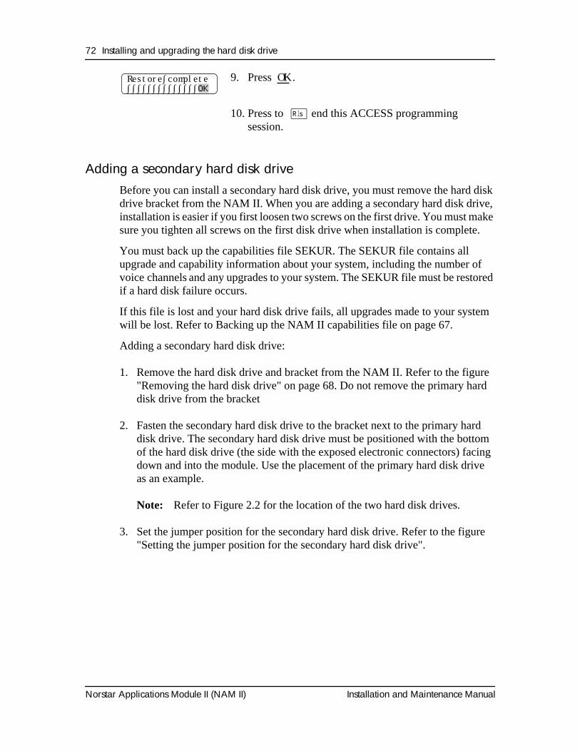
72 Installing and upgrading the hard disk drive
Norstar Applications Module II (NAM II) Installation and Maintenance Manual
Adding a secondary hard disk driveBefore you can install a secondary hard disk drive, you must remove the hard disk drive bracket from the NAM II. When you are adding a secondary hard disk drive, installation is easier if you first loosen two screws on the first drive. You must make sure you tighten all screws on the first disk drive when installation is complete.
You must back up the capabilities file SEKUR. The SEKUR file contains all upgrade and capability information about your system, including the number of voice channels and any upgrades to your system. The SEKUR file must be restored if a hard disk failure occurs.
If this file is lost and your hard disk drive fails, all upgrades made to your system will be lost. Refer to Backing up the NAM II capabilities file on page 67.
Adding a secondary hard disk drive:
1. Remove the hard disk drive and bracket from the NAM II. Refer to the figure "Removing the hard disk drive" on page 68. Do not remove the primary hard disk drive from the bracket
2. Fasten the secondary hard disk drive to the bracket next to the primary hard disk drive. The secondary hard disk drive must be positioned with the bottom of the hard disk drive (the side with the exposed electronic connectors) facing down and into the module. Use the placement of the primary hard disk drive as an example.
Note: Refer to Figure 2.2 for the location of the two hard disk drives.
3. Set the jumper position for the secondary hard disk drive. Refer to the figure "Setting the jumper position for the secondary hard disk drive".
9. Press OK
.
10. Press to
®
end this ACCESS programming session.
Restore∫complete∫∫∫∫∫∫∫∫∫∫∫∫∫∫
OK
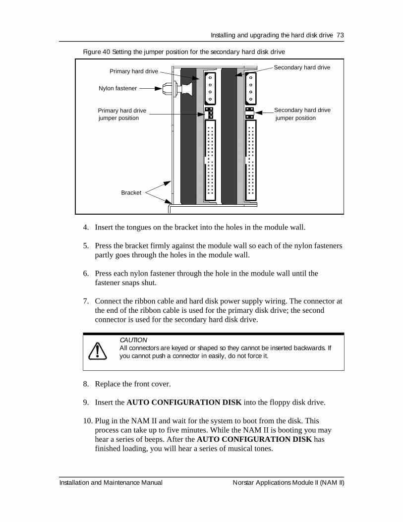
Installing and upgrading the hard disk drive 73
Installation and Maintenance Manual Norstar Applications Module II (NAM II)
Figure 40 Setting the jumper position for the secondary hard disk drive
4. Insert the tongues on the bracket into the holes in the module wall.
5. Press the bracket firmly against the module wall so each of the nylon fasteners partly goes through the holes in the module wall.
6. Press each nylon fastener through the hole in the module wall until the fastener snaps shut.
7. Connect the ribbon cable and hard disk power supply wiring. The connector at the end of the ribbon cable is used for the primary disk drive; the second connector is used for the secondary hard disk drive.
8. Replace the front cover.
9. Insert the AUTO CONFIGURATION DISK into the floppy disk drive.
10. Plug in the NAM II and wait for the system to boot from the disk. This process can take up to five minutes. While the NAM II is booting you may hear a series of beeps. After the AUTO CONFIGURATION DISK has finished loading, you will hear a series of musical tones.
CAUTION
All connectors are keyed or shaped so they cannot be inserted backwards. If you cannot push a connector in easily, do not force it.
Primary hard driveSecondary hard drive
Nylon fastener
Bracket
Primary hard drivejumper position
Secondary hard drivejumper position
74 Installing and upgrading the hard disk drive
Norstar Applications Module II (NAM II) Installation and Maintenance Manual
11. After all disk activity has ceased and the light on the floppy drive goes out, unplug the AC power to the NAM II while the musical tones are still playing. Remove the AUTO CONFIGURATION DISK from the floppy disk drive.
12. Plug in the module.
Installation and Maintenance Manual Norstar Applications Module II (NAM II)
OverviewThe internal modem is removed when a failure is suspected or confirmed. The internal modem is used for maintenance of the NAM II only. It cannot be accessed by users.
Removing the internal modemTo remove the internal modem:
1. Shutdown the module. Refer to "Shutting down the NAM II" on page 29.
2. Remove the NAM II power cord from the AC outlet.
3. Ground yourself by attaching one end of the grounding strap to your wrist and the other end to a grounded metal surface.
4. Remove the front cover. Refer to "Removing the front cover" on page 31 for more information on accessing the module.
5. Disconnect the Serial Port A and Serial Port B connectors from the SBC. Disconnect the keyboard/mouse connector from the SBC. Refer to Figure 43 on page 80.
6. Locate the internal modem card and disconnect the teladapt cord. The internal modem will be located in slot 3.
7. Remove the slot cover screw. Refer to Figure 35 on page 59.
8. Use both hands to carefully hold the internal modem card along the top. Lift the card straight up and out from the module.
Note: Sometimes the internal modem card is tightly seated and hard to remove. You may need to wiggle it out with a slight rocking motion.
Installing a new Internal modem 10
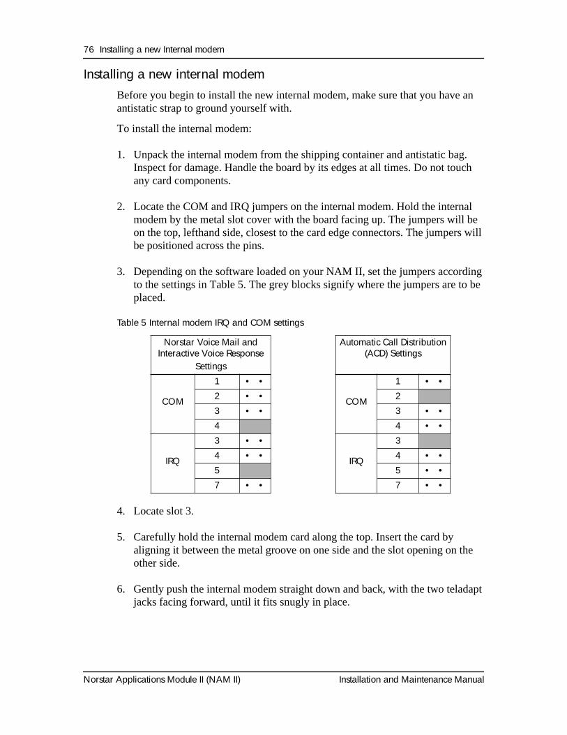
76 Installing a new Internal modem
Norstar Applications Module II (NAM II) Installation and Maintenance Manual
Installing a new internal modemBefore you begin to install the new internal modem, make sure that you have an antistatic strap to ground yourself with.
To install the internal modem:
1. Unpack the internal modem from the shipping container and antistatic bag. Inspect for damage. Handle the board by its edges at all times. Do not touch any card components.
2. Locate the COM and IRQ jumpers on the internal modem. Hold the internal modem by the metal slot cover with the board facing up. The jumpers will be on the top, lefthand side, closest to the card edge connectors. The jumpers will be positioned across the pins.
3. Depending on the software loaded on your NAM II, set the jumpers according to the settings in Table 5. The grey blocks signify where the jumpers are to be placed.
Table 5 Internal modem IRQ and COM settings
4. Locate slot 3.
5. Carefully hold the internal modem card along the top. Insert the card by aligning it between the metal groove on one side and the slot opening on the other side.
6. Gently push the internal modem straight down and back, with the two teladapt jacks facing forward, until it fits snugly in place.
Norstar Voice Mail and Interactive Voice Response
Settings
Automatic Call Distribution (ACD) Settings
COM
1 • •
COM
1 • •2 • • 2 3 • • 3 • •4 4 • •
IRQ
3 • •
IRQ
3 4 • • 4 • •5 5 • •7 • • 7 • •
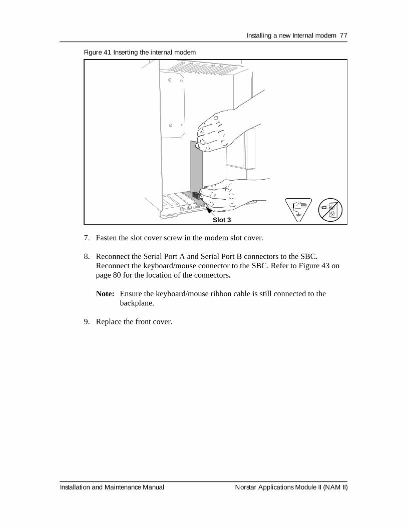
Installing a new Internal modem 77
Installation and Maintenance Manual Norstar Applications Module II (NAM II)
Figure 41 Inserting the internal modem
7. Fasten the slot cover screw in the modem slot cover.
8. Reconnect the Serial Port A and Serial Port B connectors to the SBC. Reconnect the keyboard/mouse connector to the SBC. Refer to Figure 43 on page 80 for the location of the connectors.
Note: Ensure the keyboard/mouse ribbon cable is still connected to the backplane.
9. Replace the front cover.
Install Internal Modem 1.5
Slot 3
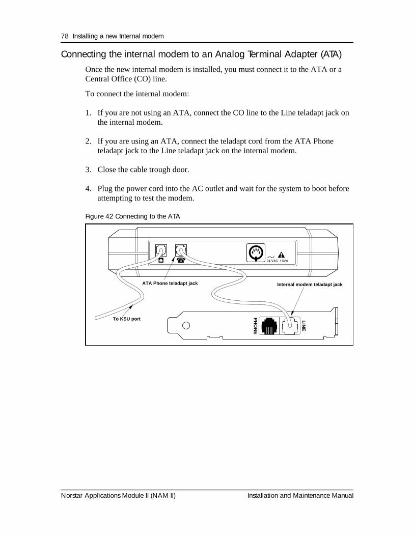
78 Installing a new Internal modem
Norstar Applications Module II (NAM II) Installation and Maintenance Manual
Connecting the internal modem to an Analog Terminal Adapter (ATA)Once the new internal modem is installed, you must connect it to the ATA or a Central Office (CO) line.
To connect the internal modem:
1. If you are not using an ATA, connect the CO line to the Line teladapt jack on the internal modem.
2. If you are using an ATA, connect the teladapt cord from the ATA Phone teladapt jack to the Line teladapt jack on the internal modem.
3. Close the cable trough door.
4. Plug the power cord into the AC outlet and wait for the system to boot before attempting to test the modem.
Figure 42 Connecting to the ATA
To KSU port
Modem Line teladapt jackATA Phone teladapt jack
PH
ON
E
LIN
E
ATA Phone teladapt jack
To KSU port
Internal modem teladapt jack
Installation and Maintenance Manual Norstar Applications Module II (NAM II)
OverviewThe NAM II is equipped with either 8 MB or 16 MB of EDO Random Access Memory (RAM). This memory is located in Single In-line Memory Modules (SIMMs) on the SBC. The first 8MB SIMM is located in memory slot 1. If the NAM II is equipped with 16 MB of RAM, there will an additional 8 MB SIMM in memory slot 2. When the NAM II is mounted on a wall, the SIMMs are on the upper left corner of the SBC. For information about the location of the SIMM slots, refer to Figure 44 on page 82.
Adding memoryYou may want to increase the amount of RAM depending on the applications running on the NAM II. You can expand the amount of RAM to:
• 16 MB with an extra 8 MB in SIMM slot 2
• 32 MB with 8 MB SIMMs in all four slots
Note: Before you begin installing additional memory SIMMs, make sure you ground yourself by attaching one end of the grounding strap to your wrist and the other end to the NAM II.
To add memory:
1. Shutdown the module. For more information, refer to "Shutting down the NAM II" on page 29.
2. Remove the NAM II power cord from the AC outlet.
3. Ground yourself by attaching one end of the grounding strap to your wrist and the other end to a grounded metal surface.
4. Remove the front cover. Refer to "Accessing the inside of the NAM II" on page 30.
Adding and replacing memory 11
CAUTION
Do not use an electric screwdriver or any other magnetized tools near the SIMMs. The SIMMs may be disrupted. Refer to "Special parts and equipment" on page 17
for equipment recommendations.
This document was created with FrameBuilder 4.0.4
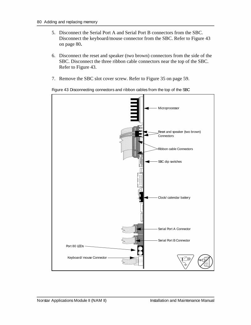
80 Adding and replacing memory
Norstar Applications Module II (NAM II) Installation and Maintenance Manual
5. Disconnect the Serial Port A and Serial Port B connectors from the SBC. Disconnect the keyboard/mouse connector from the SBC. Refer to Figure 43 on page 80.
6. Disconnect the reset and speaker (two brown) connectors from the side of the SBC. Disconnect the three ribbon cable connectors near the top of the SBC. Refer to Figure 43.
7. Remove the SBC slot cover screw. Refer to Figure 35 on page 59.
Figure 43 Disconnecting connectors and ribbon cables from the top of the SBCB
oard
Ele
vatio
n 1.
5
Serial Port A Connector
Microprocessor
Reset and speaker (two brown) Connectors
Ribbon cable Connectors
SBC dip switches
Clock/calendar battery
Serial Port B Connector
Port 80 LEDs
Keyboard/mouse Connector
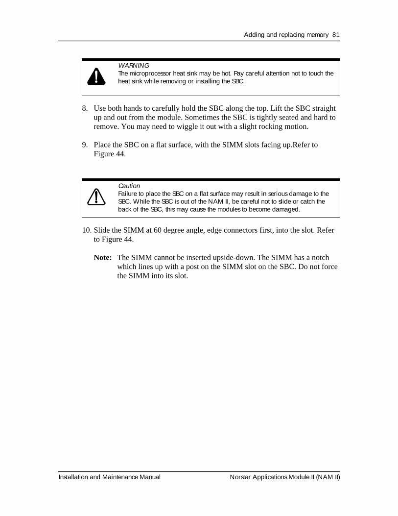
Adding and replacing memory 81
Installation and Maintenance Manual Norstar Applications Module II (NAM II)
8. Use both hands to carefully hold the SBC along the top. Lift the SBC straight up and out from the module. Sometimes the SBC is tightly seated and hard to remove. You may need to wiggle it out with a slight rocking motion.
9. Place the SBC on a flat surface, with the SIMM slots facing up.Refer to Figure 44.
10. Slide the SIMM at 60 degree angle, edge connectors first, into the slot. Refer to Figure 44.
Note: The SIMM cannot be inserted upside-down. The SIMM has a notch which lines up with a post on the SIMM slot on the SBC. Do not force the SIMM into its slot.
WARNING
The microprocessor heat sink may be hot. Pay careful attention not to touch the heat sink while removing or installing the SBC.
Caution
Failure to place the SBC on a flat surface may result in serious damage to the SBC. While the SBC is out of the NAM II, be careful not to slide or catch the back of the SBC, this may cause the modules to become damaged.
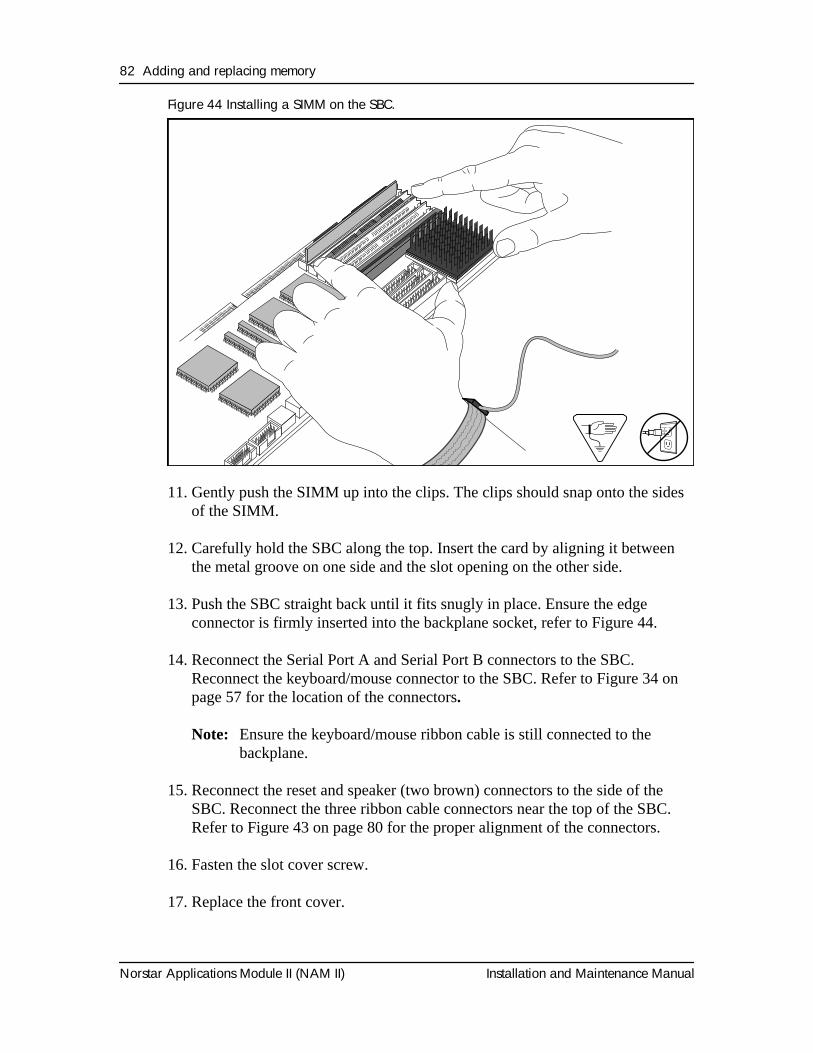
82 Adding and replacing memory
Norstar Applications Module II (NAM II) Installation and Maintenance Manual
Figure 44 Installing a SIMM on the SBC.
11. Gently push the SIMM up into the clips. The clips should snap onto the sides of the SIMM.
12. Carefully hold the SBC along the top. Insert the card by aligning it between the metal groove on one side and the slot opening on the other side.
13. Push the SBC straight back until it fits snugly in place. Ensure the edge connector is firmly inserted into the backplane socket, refer to Figure 44.
14. Reconnect the Serial Port A and Serial Port B connectors to the SBC. Reconnect the keyboard/mouse connector to the SBC. Refer to Figure 34 on page 57 for the location of the connectors.
Note: Ensure the keyboard/mouse ribbon cable is still connected to the backplane.
15. Reconnect the reset and speaker (two brown) connectors to the side of the SBC. Reconnect the three ribbon cable connectors near the top of the SBC. Refer to Figure 43 on page 80 for the proper alignment of the connectors.
16. Fasten the slot cover screw.
17. Replace the front cover.
6) Simm Install 1.6
Adding and replacing memory 83
Installation and Maintenance Manual Norstar Applications Module II (NAM II)
18. Plug the power cord into the AC outlet.
The NAM II will reboot and then automatically reboot a second time. The second reboot is necessary for the NAM II to recognize the addition of memory.
Removing memorySIMMs are usually only removed when a failure is suspected.
To remove a SIMM:
1. Shutdown the module. For more information, refer to "Shutting down the NAM II" on page 29.
2. Remove the NAM II power cord from the AC outlet.
3. Ground yourself by attaching one end of the grounding strap to your wrist and the other end to a grounded metal surface.
4. Remove module front cover. Refer to "Accessing the inside of the NAM II" on page 30.
5. Disconnect the Serial Port A and Serial Port B connectors from the SBC. Disconnect the keyboard/mouse connector from the SBC. Refer to Figure 34 on page 57.
6. Disconnect the reset and speaker (two brown) connectors from the side of the SBC. Disconnect the three ribbon cable connectors near the top of the SBC. Refer to Figure 43 on page 80.
7. Remove the SBC slot cover screw.
8. Use both hands to carefully hold the SBC along the top. Lift the SBC straight up and out from the module. Sometimes the SBC is tightly seated and hard to remove. You may need to wiggle it out with a slight rocking motion.
9. Place the SBC on a flat surface, with the SIMM slot facing up. Refer to the figure "Removing the SIMM" on page 84.
WARNING
The microprocessor heat sink may be hot. Pay careful attention not to touch the heat sink while removing or installing the SBC.
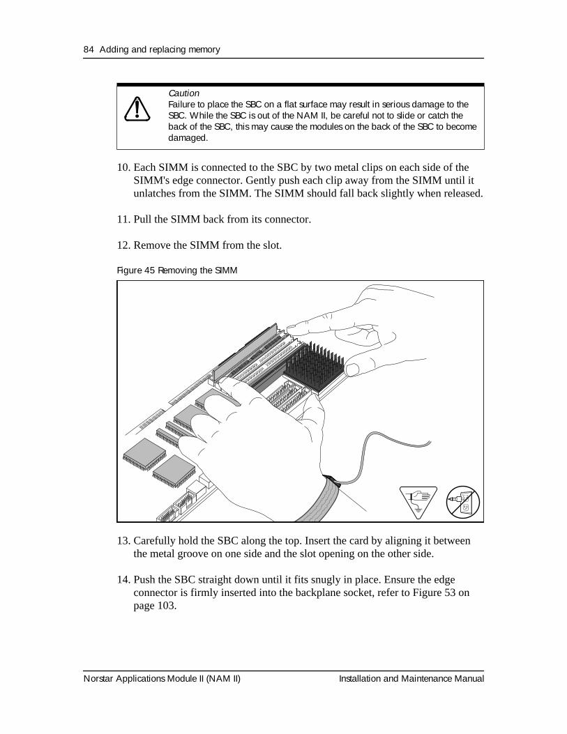
84 Adding and replacing memory
Norstar Applications Module II (NAM II) Installation and Maintenance Manual
10. Each SIMM is connected to the SBC by two metal clips on each side of the SIMM's edge connector. Gently push each clip away from the SIMM until it unlatches from the SIMM. The SIMM should fall back slightly when released.
11. Pull the SIMM back from its connector.
12. Remove the SIMM from the slot.
Figure 45 Removing the SIMM
13. Carefully hold the SBC along the top. Insert the card by aligning it between the metal groove on one side and the slot opening on the other side.
14. Push the SBC straight down until it fits snugly in place. Ensure the edge connector is firmly inserted into the backplane socket, refer to Figure 53 on page 103.
Caution
Failure to place the SBC on a flat surface may result in serious damage to the SBC. While the SBC is out of the NAM II, be careful not to slide or catch the back of the SBC, this may cause the modules on the back of the SBC to become damaged.
6) Simm Install 1.6
Adding and replacing memory 85
Installation and Maintenance Manual Norstar Applications Module II (NAM II)
15. Reconnect the Serial Port A and Serial Port B connectors to the SBC. Reconnect the keyboard/mouse connector to the SBC. Refer to Figure 43 on page 80 for the location of the connectors.
Note: Ensure the keyboard/mouse ribbon cable is still connected to the backplane.
16. Reconnect the reset and speaker (two brown) connectors to the side of the SBC. Reconnect the three ribbon cable connectors to the top of the SBC. Refer to Figure 43 on page 80 for the proper alignment of the connectors.
17. Fasten the slot cover screw.
18. Replace the front cover.
19. Plug the power cord into the AC outlet.

86 Adding and replacing memory
Norstar Applications Module II (NAM II) Installation and Maintenance Manual
Installation and Maintenance Manual Norstar Applications Module II (NAM II)
OverviewA 14 inch color monitor, a keyboard and a mouse can be added to the NAM II to allow the use of other Nortel approved software applications on the NAM II. The monitor comes with a Super Video Graphic Array (SVGA) card.
Installing the SVGA video cardThis procedure is for installing an SVGA on a NAM II that does not have Norstar Voice Mail installed.
The SVGA video card provides high text and graphic resolution and can display up to 256 colors.
To install the video card:
1. Shutdown the module.For more information, refer to "Shutting down the NAM II" on page 29.
2. Remove the NAM II power cord from the AC outlet.
3. Ground yourself by attaching one end of the grounding strap to your wrist and the other end to a grounded metal surface.
4. Remove the NAM II front cover. Refer to "Removing the front cover" on page 31.
5. Unpack the video card from the shipping container and antistatic bag. Inspect for damage. Handle the board by its edges at all times. Do not touch any card components.
6. Locate expansion bus slot 8 and remove its slot cover screw and metal slot cover.
7. Carefully hold the card along the top only and insert the card into the module by aligning it over the backplane connector.
Adding and removing a monitor, keyboard and mouse 12
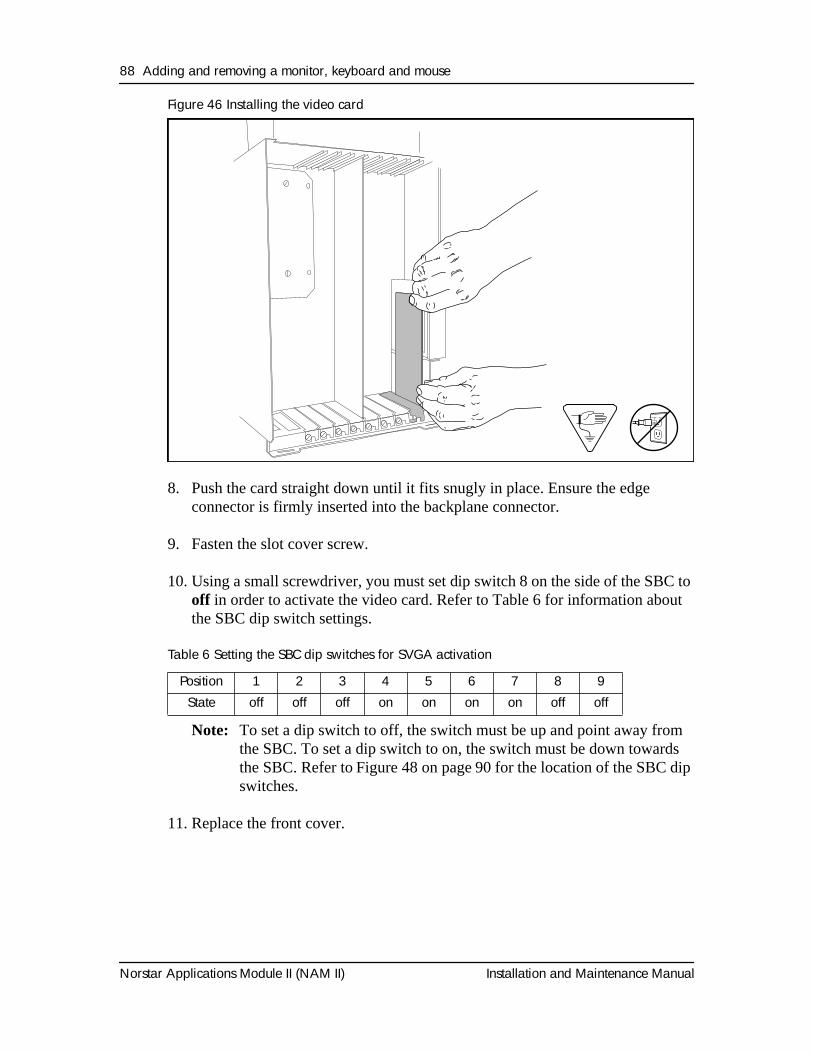
88 Adding and removing a monitor, keyboard and mouse
Norstar Applications Module II (NAM II) Installation and Maintenance Manual
Figure 46 Installing the video card
8. Push the card straight down until it fits snugly in place. Ensure the edge connector is firmly inserted into the backplane connector.
9. Fasten the slot cover screw.
10. Using a small screwdriver, you must set dip switch 8 on the side of the SBC to off in order to activate the video card. Refer to Table 6 for information about the SBC dip switch settings.
Table 6 Setting the SBC dip switches for SVGA activation
Note: To set a dip switch to off, the switch must be up and point away from the SBC. To set a dip switch to on, the switch must be down towards the SBC. Refer to Figure 48 on page 90 for the location of the SBC dip switches.
11. Replace the front cover.
Position 1 2 3 4 5 6 7 8 9State off off off on on on on off off
Install Video Card 1.5
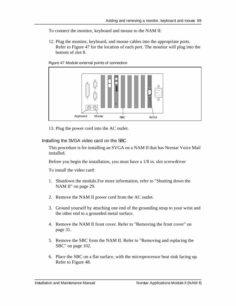
Adding and removing a monitor, keyboard and mouse 89
Installation and Maintenance Manual Norstar Applications Module II (NAM II)
To connect the monitor, keyboard and mouse to the NAM II:
12. Plug the monitor, keyboard, and mouse cables into the appropriate ports. Refer to Figure 47 for the location of each port. The monitor will plug into the bottom of slot 8.
Figure 47 Module external points of connection
13. Plug the power cord into the AC outlet.
Installing the SVGA video card on the SBCThis procedure is for installing an SVGA on a NAM II that has Norstar Voice Mail installed.
Before you begin the installation, you must have a 1/8 in. slot screwdriver
To install the video card:
1. Shutdown the module.For more information, refer to "Shutting down the NAM II" on page 29.
2. Remove the NAM II power cord from the AC outlet.
3. Ground yourself by attaching one end of the grounding strap to your wrist and the other end to a grounded metal surface.
4. Remove the NAM II front cover. Refer to "Removing the front cover" on page 31.
5. Remove the SBC from the NAM II. Refer to "Removing and replacing the SBC" on page 102.
6. Place the SBC on a flat surface, with the microprocessor heat sink facing up. Refer to Figure 48.
12
34
56
78
Keyboard Mouse SVGA
SBC
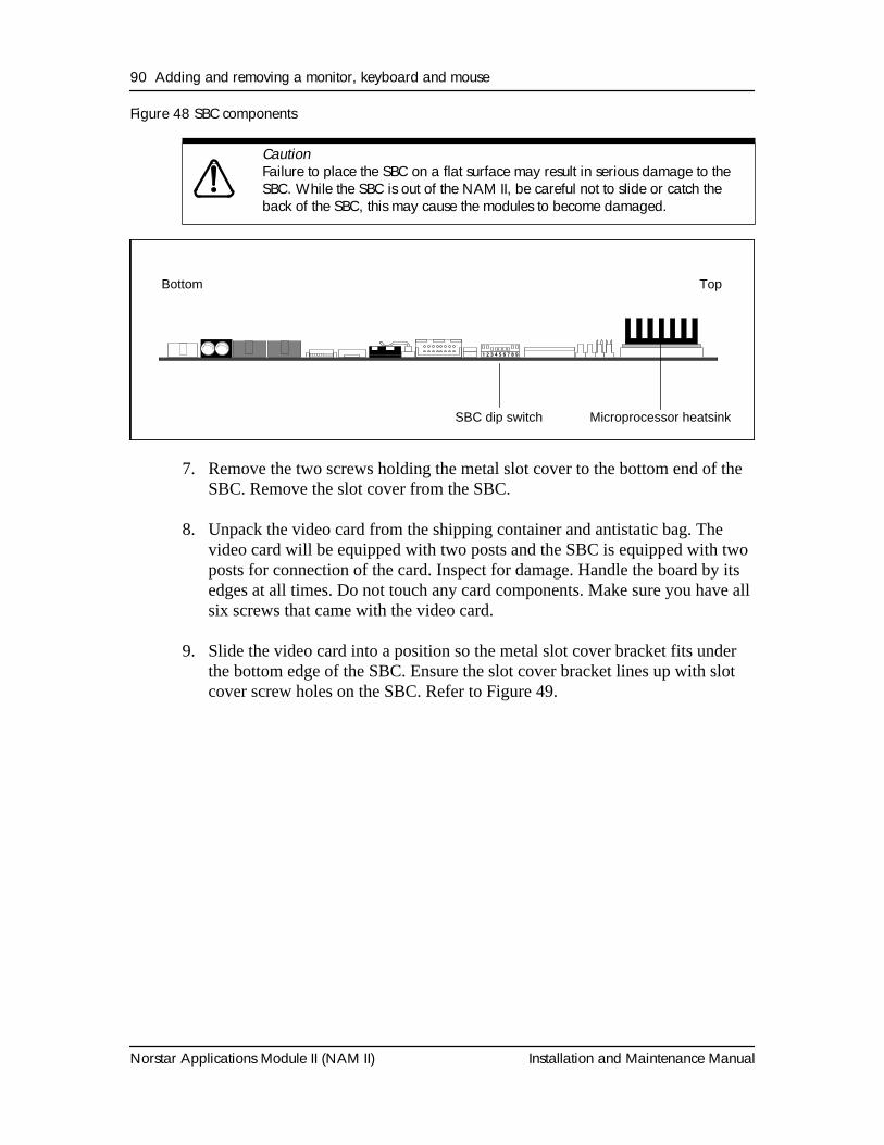
90 Adding and removing a monitor, keyboard and mouse
Norstar Applications Module II (NAM II) Installation and Maintenance Manual
Figure 48 SBC components
7. Remove the two screws holding the metal slot cover to the bottom end of the SBC. Remove the slot cover from the SBC.
8. Unpack the video card from the shipping container and antistatic bag. The video card will be equipped with two posts and the SBC is equipped with two posts for connection of the card. Inspect for damage. Handle the board by its edges at all times. Do not touch any card components. Make sure you have all six screws that came with the video card.
9. Slide the video card into a position so the metal slot cover bracket fits under the bottom edge of the SBC. Ensure the slot cover bracket lines up with slot cover screw holes on the SBC. Refer to Figure 49.
Caution
Failure to place the SBC on a flat surface may result in serious damage to the SBC. While the SBC is out of the NAM II, be careful not to slide or catch the back of the SBC, this may cause the modules to become damaged.
Microprocessor heatsink SBC dip switch
TopBottom
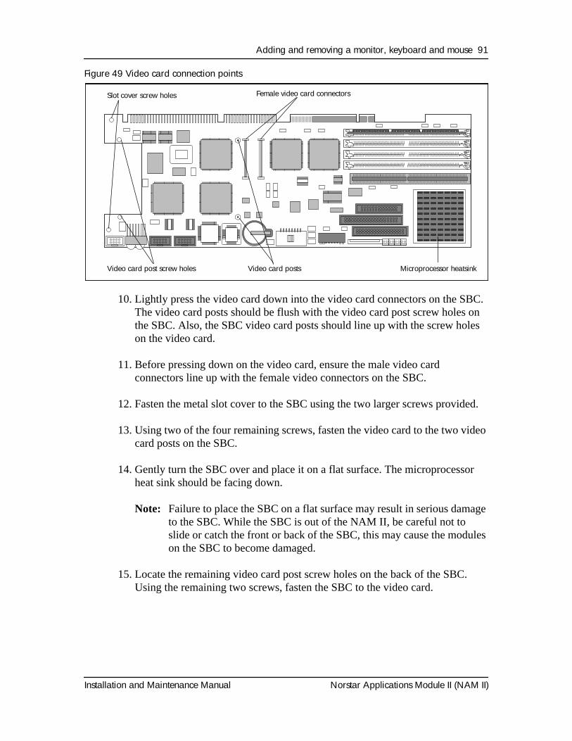
Adding and removing a monitor, keyboard and mouse 91
Installation and Maintenance Manual Norstar Applications Module II (NAM II)
Figure 49 Video card connection points
10. Lightly press the video card down into the video card connectors on the SBC. The video card posts should be flush with the video card post screw holes on the SBC. Also, the SBC video card posts should line up with the screw holes on the video card.
11. Before pressing down on the video card, ensure the male video card connectors line up with the female video connectors on the SBC.
12. Fasten the metal slot cover to the SBC using the two larger screws provided.
13. Using two of the four remaining screws, fasten the video card to the two video card posts on the SBC.
14. Gently turn the SBC over and place it on a flat surface. The microprocessor heat sink should be facing down.
Note: Failure to place the SBC on a flat surface may result in serious damage to the SBC. While the SBC is out of the NAM II, be careful not to slide or catch the front or back of the SBC, this may cause the modules on the SBC to become damaged.
15. Locate the remaining video card post screw holes on the back of the SBC. Using the remaining two screws, fasten the SBC to the video card.
5) Board Plan View 1.6
Female video card connectors Slot cover screw holes
Video card post screw holes Microprocessor heatsinkVideo card posts
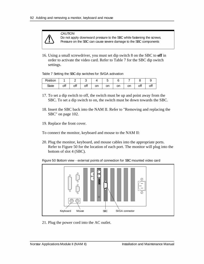
92 Adding and removing a monitor, keyboard and mouse
Norstar Applications Module II (NAM II) Installation and Maintenance Manual
16. Using a small screwdriver, you must set dip switch 8 on the SBC to off in order to activate the video card. Refer to Table 7 for the SBC dip switch settings.
Table 7 Setting the SBC dip switches for SVGA activation
17. To set a dip switch to off, the switch must be up and point away from the SBC. To set a dip switch to on, the switch must be down towards the SBC.
18. Insert the SBC back into the NAM II. Refer to "Removing and replacing the SBC" on page 102.
19. Replace the front cover.
To connect the monitor, keyboard and mouse to the NAM II:
20. Plug the monitor, keyboard, and mouse cables into the appropriate ports. Refer to Figure 50 for the location of each port. The monitor will plug into the bottom of slot 4 (SBC).
Figure 50 Bottom view - external points of connection for SBC mounted video card
21. Plug the power cord into the AC outlet.
CAUTION
Do not apply downward pressure to the SBC while fastening the screws. Pressure on the SBC can cause severe damage to the SBC components
Position 1 2 3 4 5 6 7 8 9State off off off on on on on off off
12
34
56
78
Keyboard Mouse SVGA connector
SBC
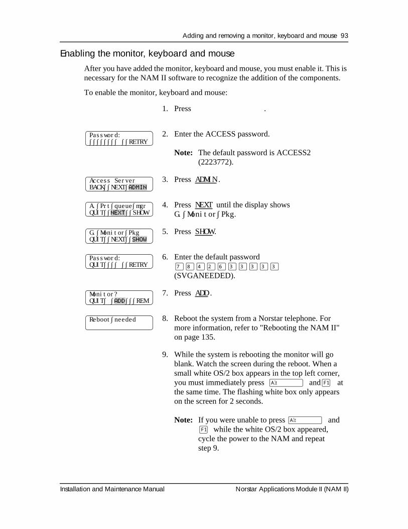
Adding and removing a monitor, keyboard and mouse 93
Installation and Maintenance Manual Norstar Applications Module II (NAM II)
Enabling the monitor, keyboard and mouseAfter you have added the monitor, keyboard and mouse, you must enable it. This is necessary for the NAM II software to recognize the addition of the components.
To enable the monitor, keyboard and mouse:
1. Press
Ä áÚÞ
.
2. Enter the ACCESS password.
Note:
The default password is ACCESS2 (2223772).
3. Press
ADMIN
.
4. Press
NEXT
until the display shows
G.∫Monitor∫Pkg
.
5. Press
SHOW
.
6. Enter the default password
‡°›¤fl‹‹‹‹‹
(SVGANEEDED).
7. Press
ADD
.
8. Reboot the system from a Norstar telephone. For more information, refer to "Rebooting the NAM II" on page 135.
9. While the system is rebooting the monitor will go blank. Watch the screen during the reboot. When a small white OS/2 box appears in the top left corner, you must immediately press
∫Alt
and
åF1
at the same time. The flashing white box only appears on the screen for 2 seconds.
Note:
If you were unable to press
∫Alt
and
åF1
while the white OS/2 box appeared, cycle the power to the NAM and repeat step 9.
Password:∫∫∫∫∫∫∫∫ ∫∫RETRY
Access ServerBACK∫∫NEXT∫
ADMIN
A.∫Prt∫queue∫mgrQUIT∫∫
NEXT
∫∫SHOW
G.∫Monitor∫PkgQUIT∫∫NEXT∫∫
SHOW
Password:QUIT∫∫∫∫ ∫∫RETRY
Monitor?QUIT∫ ∫
ADD
∫∫∫REM
Reboot∫needed
94 Adding and removing a monitor, keyboard and mouse
Norstar Applications Module II (NAM II) Installation and Maintenance Manual
10. When the Recovery Choices screen appears on the monitor, press
◊
on the keyboard.
11. The monitor, keyboard and mouse have now been initialized and enabled.
Note:
Steps 9 and 10 are part of a first time monitor initialization process. If the monitor, keyboard and mouse are removed from the NAM II, only steps 1 through 8 need to be performed to re-enable the monitor package.
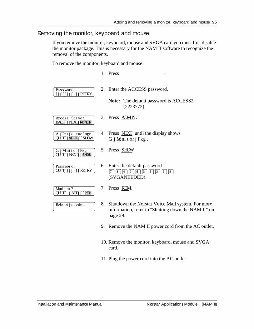
Adding and removing a monitor, keyboard and mouse 95
Installation and Maintenance Manual Norstar Applications Module II (NAM II)
Removing the monitor, keyboard and mouseIf you remove the monitor, keyboard, mouse and SVGA card you must first disable the monitor package. This is necessary for the NAM II software to recognize the removal of the components.
To remove the monitor, keyboard and mouse:
1. Press
Ä áÚÞ
.
2. Enter the ACCESS password.
Note:
The default password is ACCESS2 (2223772).
3. Press
ADMIN
.
4. Press
NEXT
until the display shows
G.∫Monitor∫Pkg
.
5. Press
SHOW
.
6. Enter the default password
‡°›¤fl‹‹‹‹‹
(SVGANEEDED).
7. Press
REM
.
8. Shutdown the Norstar Voice Mail system. For more information, refer to "Shutting down the NAM II" on page 29.
9. Remove the NAM II power cord from the AC outlet.
10. Remove the monitor, keyboard, mouse and SVGA card.
11. Plug the power cord into the AC outlet.
Password:∫∫∫∫∫∫∫∫ ∫∫RETRY
Access ServerBACK∫∫NEXT∫
ADMIN
A.∫Prt∫queue∫mgrQUIT∫∫
NEXT
∫∫SHOW
G.∫Monitor∫PkgQUIT∫∫NEXT∫∫
SHOW
Password:QUIT∫∫∫∫ ∫∫RETRY
Monitor?QUIT∫ ∫ADD∫∫∫
REM
Reboot∫needed
96 Adding and removing a monitor, keyboard and mouse
Norstar Applications Module II (NAM II) Installation and Maintenance Manual
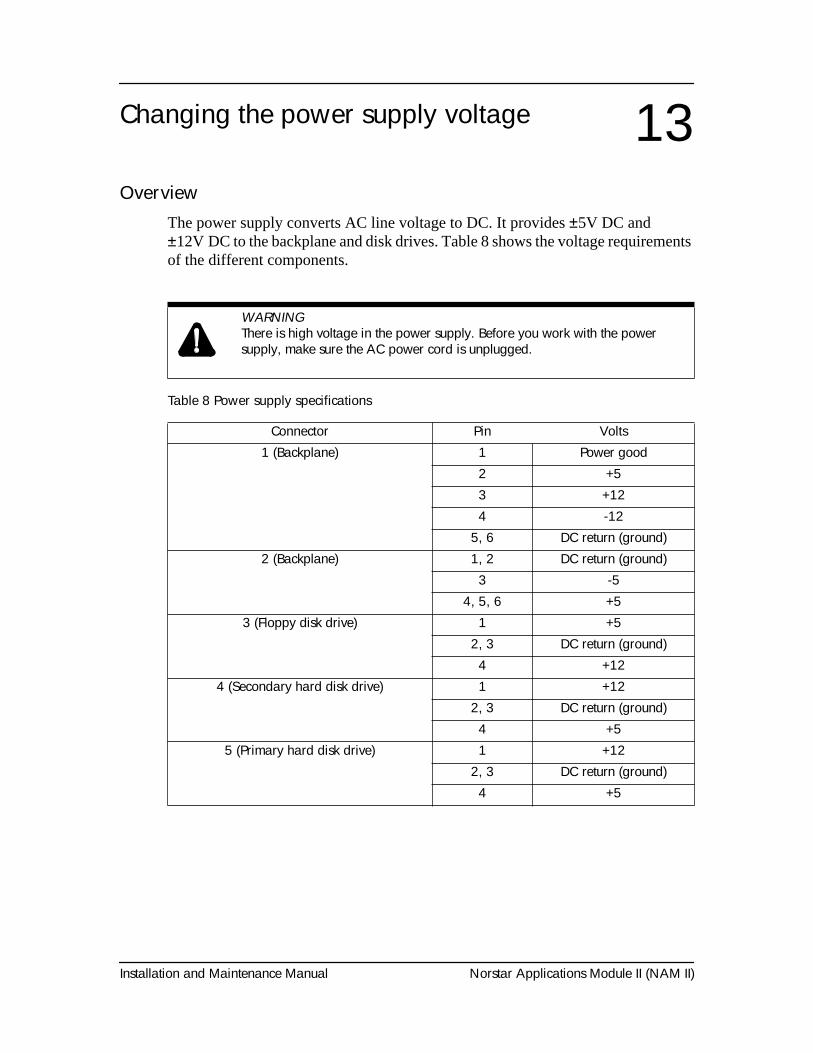
Installation and Maintenance Manual Norstar Applications Module II (NAM II)
OverviewThe power supply converts AC line voltage to DC. It provides ±5V DC and ±12V DC to the backplane and disk drives. Table 8 shows the voltage requirements of the different components.
Table 8 Power supply specifications
Changing the power supply voltage 13
WARNING
There is high voltage in the power supply. Before you work with the power supply, make sure the AC power cord is unplugged.
Connector Pin Volts
1 (Backplane) 1 Power good2 +53 +124 -12
5, 6 DC return (ground)2 (Backplane) 1, 2 DC return (ground)
3 -54, 5, 6 +5
3 (Floppy disk drive) 1 +52, 3 DC return (ground)4 +12
4 (Secondary hard disk drive) 1 +122, 3 DC return (ground)4 +5
5 (Primary hard disk drive) 1 +122, 3 DC return (ground)4 +5
This document was created with FrameBuilder 4.0.4
98 Changing the power supply voltage
Norstar Applications Module II (NAM II) Installation and Maintenance Manual
Changing the power supply voltageThe power supply is set at the factory to operate at 115 volts, but the power supply can be changed to operate at 230 volts for countries where this is the standard. If you are changing the power supply voltage setting to 230 volts, the NAM II must be unplugged and removed from its wall mount.
To change the power supply setting:
1. Shutdown the NAM II. For more information, refer to "Shutting down the NAM II" on page 29.
2. Remove the NAM II power cord from the AC outlet.
3. Remove the module from its wall mount. Access to the voltage switch is through the top rear right-hand corner of the unit.
Note: If the module is on a floor mount stand, you do not need to remove it from the stand.
4. Slide the slider switch, mounted on the top of the power supply, so that the desired voltage label is shown (115 or 230).
5. Replace the module on its wall mount.
6. Plug the power cord into the AC outlet.
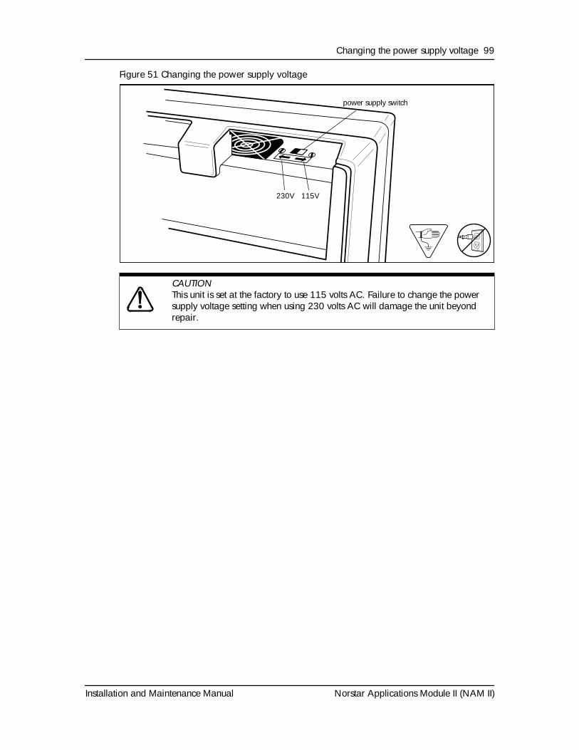
Changing the power supply voltage 99
Installation and Maintenance Manual Norstar Applications Module II (NAM II)
Figure 51 Changing the power supply voltage
CAUTION
This unit is set at the factory to use 115 volts AC. Failure to change the power supply voltage setting when using 230 volts AC will damage the unit beyond repair.
230V 115V
power supply switch
100 Changing the power supply voltage
Norstar Applications Module II (NAM II) Installation and Maintenance Manual
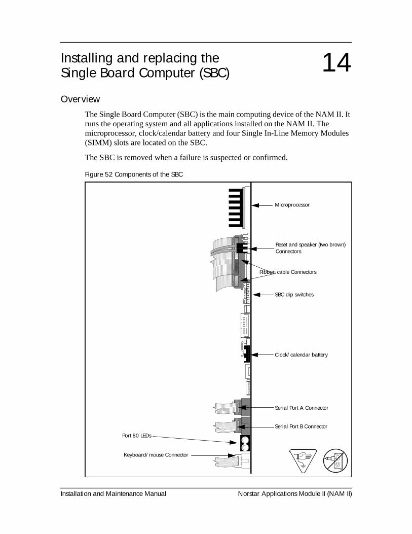
Installation and Maintenance Manual Norstar Applications Module II (NAM II)
OverviewThe Single Board Computer (SBC) is the main computing device of the NAM II. It runs the operating system and all applications installed on the NAM II. The microprocessor, clock/calendar battery and four Single In-Line Memory Modules (SIMM) slots are located on the SBC.
The SBC is removed when a failure is suspected or confirmed.
Figure 52 Components of the SBC
Installing and replacing the Single Board Computer (SBC) 14
Boa
rd E
leva
tion
1.5
Serial Port A Connector
Microprocessor
Reset and speaker (two brown) Connectors
Ribbon cable Connectors
SBC dip switches
Clock/calendar battery
Serial Port B Connector
Port 80 LEDs
Keyboard/mouse Connector
102 Installing and replacing the Single Board Computer (SBC)
Norstar Applications Module II (NAM II) Installation and Maintenance Manual
Removing and replacing the SBCTo remove and replace the SBC:
1. Shutdown the NAM II. For more information, refer to "Shutting down the NAM II" on page 29.
2. Remove the NAM II power cord from the AC outlet.
3. Ground yourself by attaching one end of the grounding strap to your wrist and the other end to a grounded metal surface.
4. Remove the NAM II front cover. Refer to "Accessing the inside of the NAM II" on page 30.
5. Locate slot 4 and remove its slot cover screw and metal slot cover.
6. Disconnect the Serial Port A and Serial Port B connectors from the SBC. Disconnect the keyboard/mouse connector from the SBC. Refer to Figure 43 on page 80.
7. Disconnect the reset and speaker (two brown) connectors from the side of the SBC. Disconnect the three ribbon cable connectors from the top of the SBC. Refer to Figure 43 on page 80.
8. Use both hands to carefully hold the SBC along the top. Lift the SBC straight up and out from the module. Sometimes the SBC is tightly seated and hard to remove. You may need to wiggle it out with a slight rocking motion.
9. If you are returning the NAM II for service, place the SBC in an antistatic bag. Package the SBC with plenty of shock-absorbing, insulating material.
10. Unpack the replacement SBC from the shipping container and antistatic bag. Inspect for damage. Handle the board by its edges at all times. Do not touch any card components.
11. Carefully hold the card along the top only and insert the card into the module by aligning it over the backplane connector.
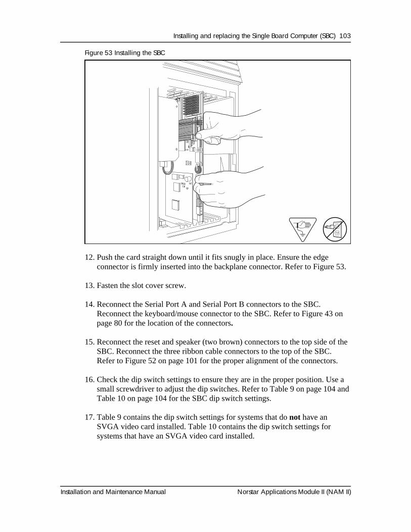
Installing and replacing the Single Board Computer (SBC) 103
Installation and Maintenance Manual Norstar Applications Module II (NAM II)
Figure 53 Installing the SBC
12. Push the card straight down until it fits snugly in place. Ensure the edge connector is firmly inserted into the backplane connector. Refer to Figure 53.
13. Fasten the slot cover screw.
14. Reconnect the Serial Port A and Serial Port B connectors to the SBC. Reconnect the keyboard/mouse connector to the SBC. Refer to Figure 43 on page 80 for the location of the connectors.
15. Reconnect the reset and speaker (two brown) connectors to the top side of the SBC. Reconnect the three ribbon cable connectors to the top of the SBC. Refer to Figure 52 on page 101 for the proper alignment of the connectors.
16. Check the dip switch settings to ensure they are in the proper position. Use a small screwdriver to adjust the dip switches. Refer to Table 9 on page 104 and Table 10 on page 104 for the SBC dip switch settings.
17. Table 9 contains the dip switch settings for systems that do not have an SVGA video card installed. Table 10 contains the dip switch settings for systems that have an SVGA video card installed.
8) Board Install 1.6
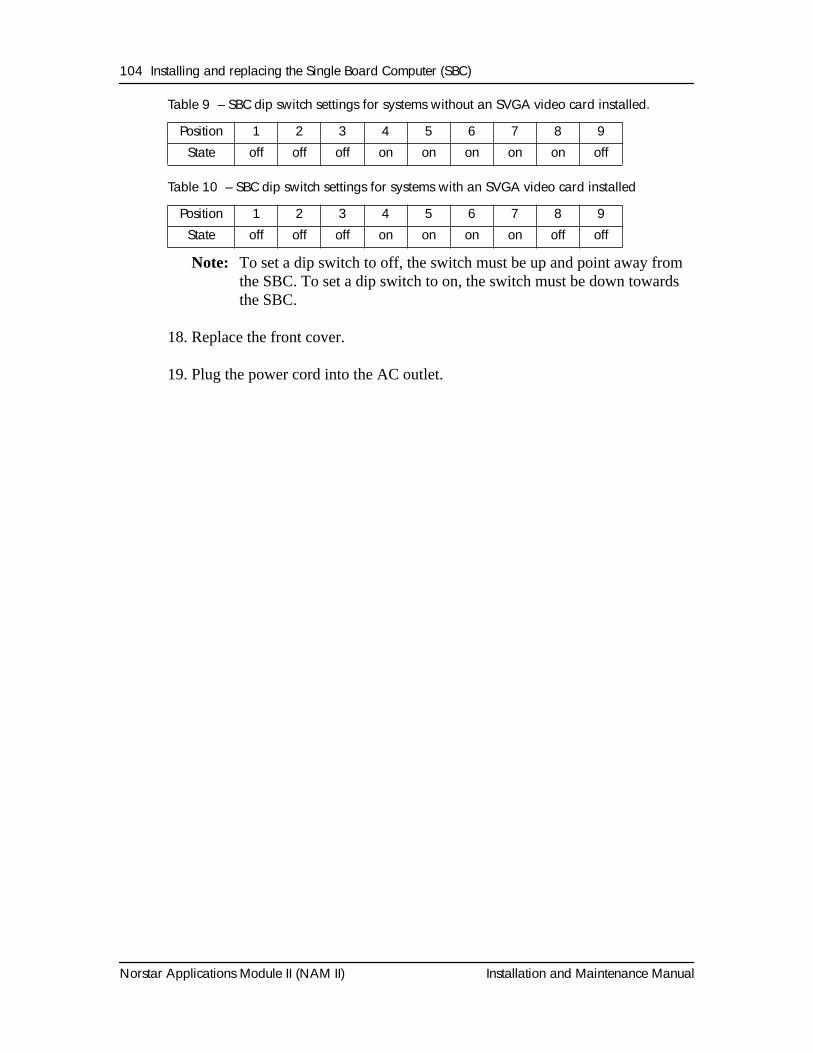
104 Installing and replacing the Single Board Computer (SBC)
Norstar Applications Module II (NAM II) Installation and Maintenance Manual
Table 9 – SBC dip switch settings for systems without an SVGA video card installed.
Table 10 – SBC dip switch settings for systems with an SVGA video card installed
Note: To set a dip switch to off, the switch must be up and point away from the SBC. To set a dip switch to on, the switch must be down towards the SBC.
18. Replace the front cover.
19. Plug the power cord into the AC outlet.
Position 1 2 3 4 5 6 7 8 9State off off off on on on on on off
Position 1 2 3 4 5 6 7 8 9State off off off on on on on off off
Installation and Maintenance Manual Norstar Applications Module II (NAM II)
Section IV - ACCESS ServerAdministration
• Preparing to use the ACCESS Server administration software• ACCESS Server administration software from a terminal
• ACCESS Server administration software from a telephone set
106 ACCESS Server Administration
Norstar Applications Module II (NAM II) Installation and Maintenance Manual
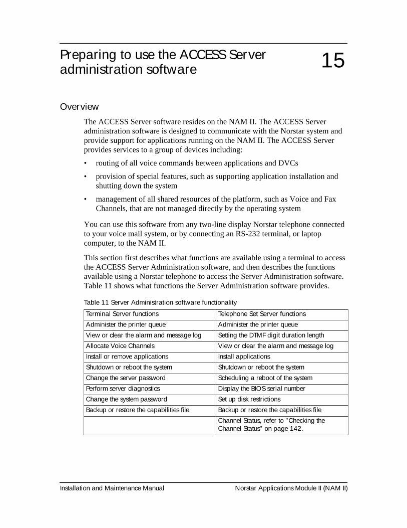
Installation and Maintenance Manual Norstar Applications Module II (NAM II)
Preparing to use the ACCESS Server administration software
OverviewThe ACCESS Server software resides on the NAM II. The ACCESS Server administration software is designed to communicate with the Norstar system and provide support for applications running on the NAM II. The ACCESS Server provides services to a group of devices including:
• routing of all voice commands between applications and DVCs
• provision of special features, such as supporting application installation and shutting down the system
• management of all shared resources of the platform, such as Voice and Fax Channels, that are not managed directly by the operating system
You can use this software from any two-line display Norstar telephone connected to your voice mail system, or by connecting an RS-232 terminal, or laptop computer, to the NAM II.
This section first describes what functions are available using a terminal to access the ACCESS Server Administration software, and then describes the functions available using a Norstar telephone to access the Server Administration software. Table 11 shows what functions the Server Administration software provides.
Table 11 Server Administration software functionality
Terminal Server functions Telephone Set Server functionsAdminister the printer queue Administer the printer queueView or clear the alarm and message log Setting the DTMF digit duration lengthAllocate Voice Channels View or clear the alarm and message logInstall or remove applications Install applicationsShutdown or reboot the system Shutdown or reboot the systemChange the server password Scheduling a reboot of the systemPerform server diagnostics Display the BIOS serial numberChange the system password Set up disk restrictionsBackup or restore the capabilities file Backup or restore the capabilities file
Channel Status, refer to "Checking the Channel Status" on page 142.
15
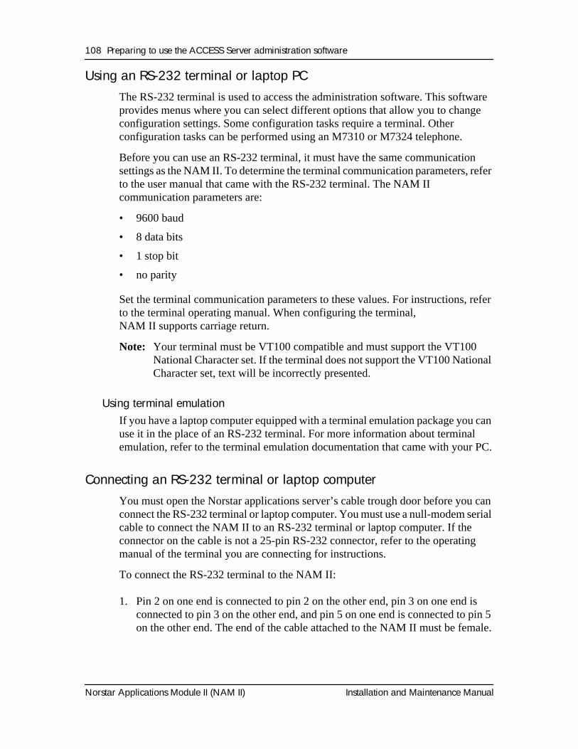
108 Preparing to use the ACCESS Server administration software
Norstar Applications Module II (NAM II) Installation and Maintenance Manual
Using an RS-232 terminal or laptop PCThe RS-232 terminal is used to access the administration software. This software provides menus where you can select different options that allow you to change configuration settings. Some configuration tasks require a terminal. Other configuration tasks can be performed using an M7310 or M7324 telephone.
Before you can use an RS-232 terminal, it must have the same communication settings as the NAM II. To determine the terminal communication parameters, refer to the user manual that came with the RS-232 terminal. The NAM II communication parameters are:
• 9600 baud
• 8 data bits
• 1 stop bit
• no parity
Set the terminal communication parameters to these values. For instructions, refer to the terminal operating manual. When configuring the terminal, NAM II supports carriage return.
Note: Your terminal must be VT100 compatible and must support the VT100 National Character set. If the terminal does not support the VT100 National Character set, text will be incorrectly presented.
Using terminal emulationIf you have a laptop computer equipped with a terminal emulation package you can use it in the place of an RS-232 terminal. For more information about terminal emulation, refer to the terminal emulation documentation that came with your PC.
Connecting an RS-232 terminal or laptop computerYou must open the Norstar applications server’s cable trough door before you can connect the RS-232 terminal or laptop computer. You must use a null-modem serial cable to connect the NAM II to an RS-232 terminal or laptop computer. If the connector on the cable is not a 25-pin RS-232 connector, refer to the operating manual of the terminal you are connecting for instructions.
To connect the RS-232 terminal to the NAM II:
1. Pin 2 on one end is connected to pin 2 on the other end, pin 3 on one end is connected to pin 3 on the other end, and pin 5 on one end is connected to pin 5 on the other end. The end of the cable attached to the NAM II must be female.
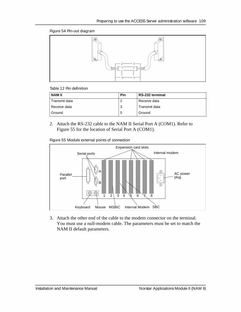
Preparing to use the ACCESS Server administration software 109
Installation and Maintenance Manual Norstar Applications Module II (NAM II)
Figure 54 Pin-out diagram
Table 12 Pin definition
2. Attach the RS-232 cable to the NAM II Serial Port A (COM1). Refer to Figure 55 for the location of Serial Port A (COM1).
Figure 55 Module external points of connection
3. Attach the other end of the cable to the modem connector on the terminal. You must use a null-modem cable. The parameters must be set to match the NAM II default parameters.
NAM II Pin RS-232 terminal
Transmit data 2 Receive data
Receive data 3 Transmit data
Ground 5 Ground
5
23
5
32
Parallelport
Serial ports
Expansion card slots
AC powerplug
Keyboard Mouse Internal ModemMSBIC
1 2 3 4 5 6 7 8
A
B
Internal modem
SBC
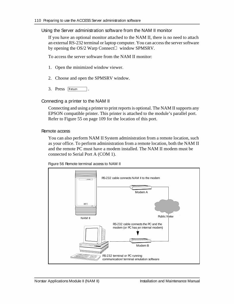
110 Preparing to use the ACCESS Server administration software
Norstar Applications Module II (NAM II) Installation and Maintenance Manual
Using the Server administration software from the NAM II monitorIf you have an optional monitor attached to the NAM II, there is no need to attach an external RS-232 terminal or laptop computer. You can access the server software by opening the OS/2 Warp Connect window SPMSRV.
To access the server software from the NAM II monitor:
1. Open the minimized window viewer.
2. Choose and open the SPMSRV window.
3. Press
∫Return
.
Connecting a printer to the NAM II
Connecting and using a printer to print reports is optional. The NAM II supports any EPSON compatible printer. This printer is attached to the module’s parallel port. Refer to Figure 55 on page 109 for the location of this port.
Remote access
You can also perform NAM II System administration from a remote location, such as your office. To perform administration from a remote location, both the NAM II and the remote PC must have a modem installed. The NAM II modem must be connected to Serial Port A (COM 1).
Figure 56 Remote terminal access to NAM II
Modem A
NAM II Public Network
Modem B
RS-232 cable connects the PC and themodem (or PC has an internal modem)
RS-232 terminal or PC running communication/terminal emulation software
RS-232 cable connects NAM II to the modem
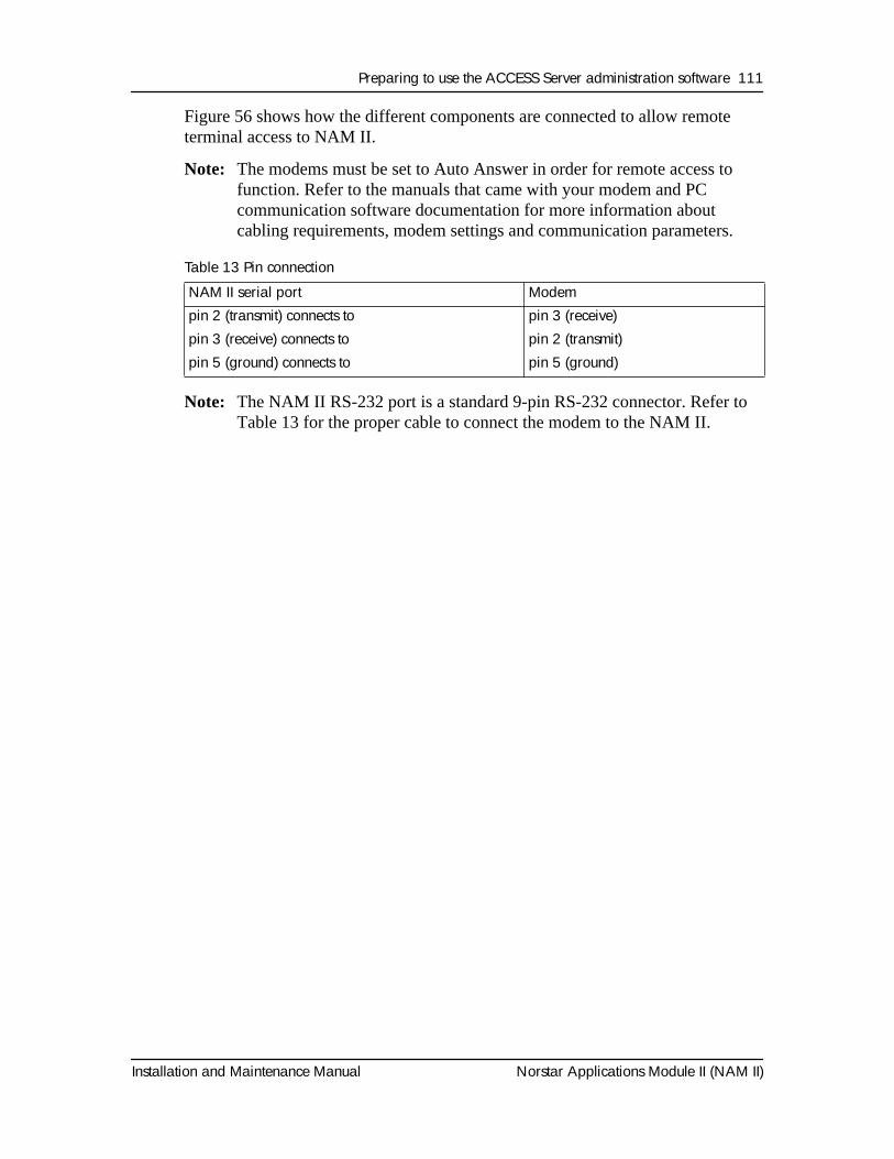
Preparing to use the ACCESS Server administration software 111
Installation and Maintenance Manual Norstar Applications Module II (NAM II)
Figure 56 shows how the different components are connected to allow remote terminal access to NAM II.
Note: The modems must be set to Auto Answer in order for remote access to function. Refer to the manuals that came with your modem and PC communication software documentation for more information about cabling requirements, modem settings and communication parameters.
Table 13 Pin connection
Note: The NAM II RS-232 port is a standard 9-pin RS-232 connector. Refer to Table 13 for the proper cable to connect the modem to the NAM II.
NAM II serial port Modempin 2 (transmit) connects to pin 3 (receive)pin 3 (receive) connects to pin 2 (transmit)pin 5 (ground) connects to pin 5 (ground)
112 Preparing to use the ACCESS Server administration software
Norstar Applications Module II (NAM II) Installation and Maintenance Manual
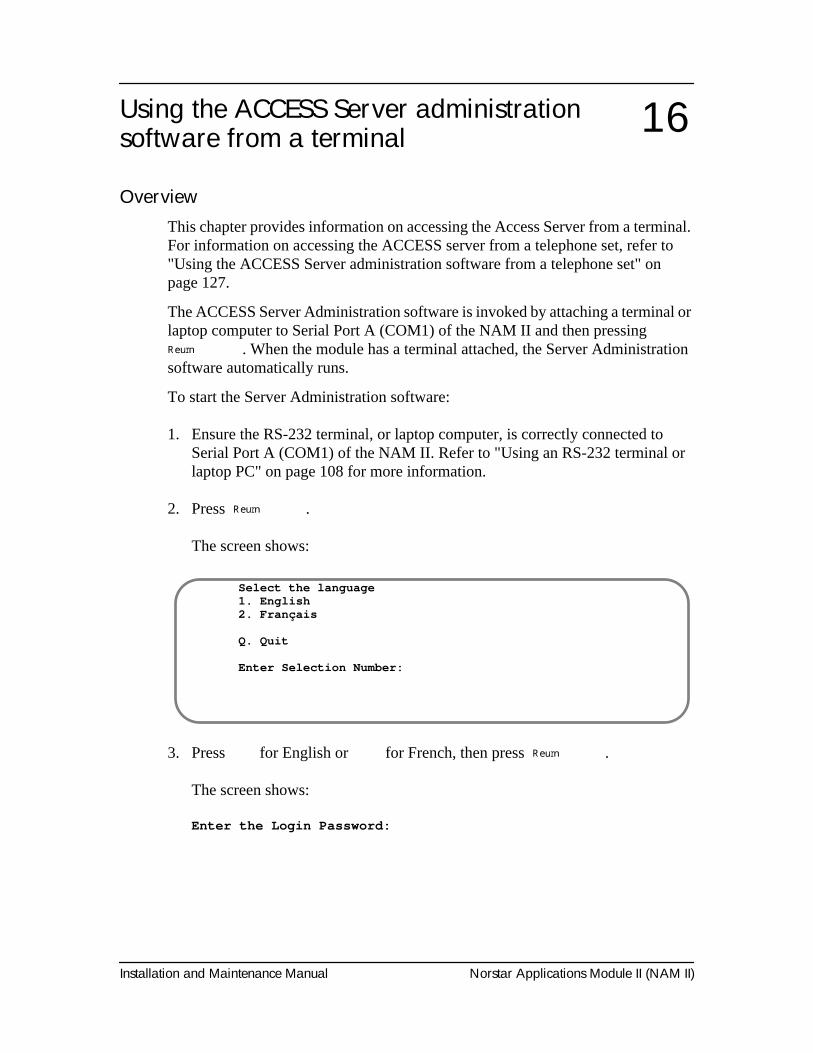
Installation and Maintenance Manual Norstar Applications Module II (NAM II)
Using the ACCESS Server administration software from a terminal
OverviewThis chapter provides information on accessing the Access Server from a terminal. For information on accessing the ACCESS server from a telephone set, refer to "Using the ACCESS Server administration software from a telephone set" on page 127.
The ACCESS Server Administration software is invoked by attaching a terminal or laptop computer to Serial Port A (COM1) of the NAM II and then pressing
ºReturn
. When the module has a terminal attached, the Server Administration software automatically runs.
To start the Server Administration software:
1. Ensure the RS-232 terminal, or laptop computer, is correctly connected to Serial Port A (COM1) of the NAM II. Refer to "Using an RS-232 terminal or laptop PC" on page 108 for more information.
2. Press
ºReturn
.
The screen shows:
3. Press
Ú
for English or
Û
for French, then press
ºReturn
.
The screen shows:
Enter the Login Password:
16
Select the language1. English2. Français
Q. Quit
Enter Selection Number:
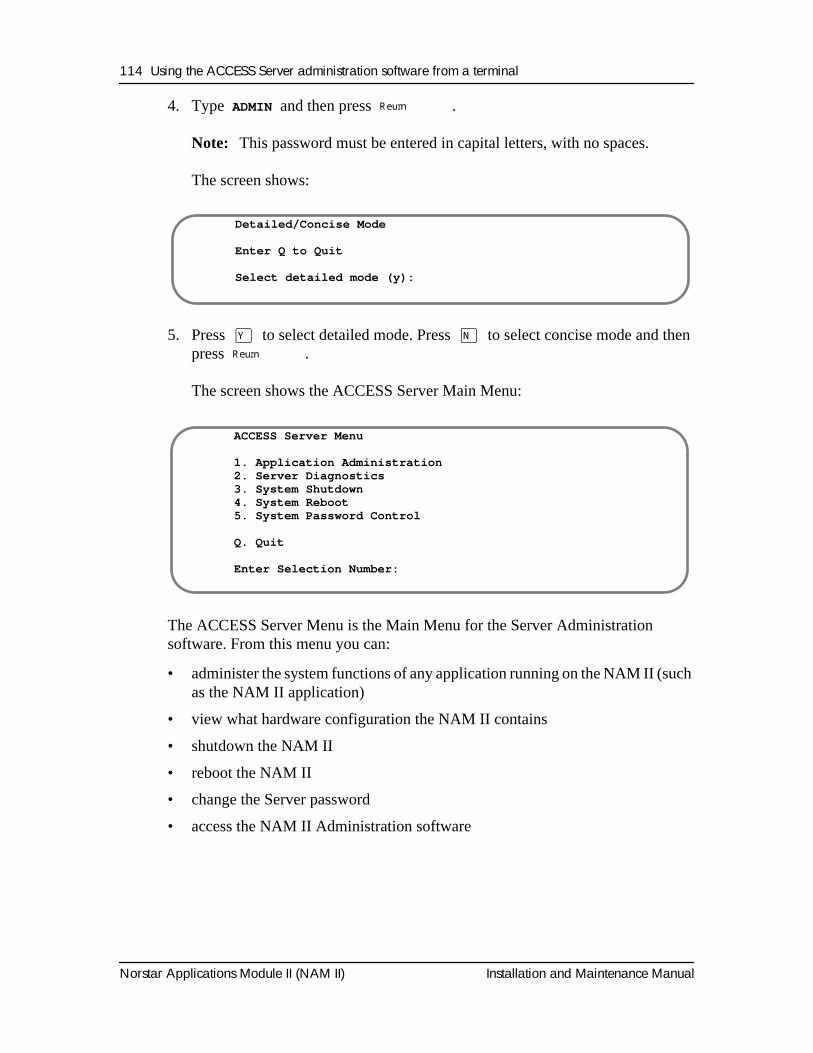
114 Using the ACCESS Server administration software from a terminal
Norstar Applications Module II (NAM II) Installation and Maintenance Manual
4. Type ADMIN and then press
ºReturn
.
Note:
This password must be entered in capital letters, with no spaces.
The screen shows:
5. Press
Á
to select detailed mode. Press
ˆ
to select concise mode and then press
ºReturn
.
The screen shows the ACCESS Server Main Menu:
The ACCESS Server Menu is the Main Menu for the Server Administration software. From this menu you can:
• administer the system functions of any application running on the NAM II (such as the NAM II application)
• view what hardware configuration the NAM II contains
• shutdown the NAM II
• reboot the NAM II
• change the Server password
• access the NAM II Administration software
Detailed/Concise Mode
Enter Q to Quit
Select detailed mode (y):
ACCESS Server Menu
1. Application Administration2. Server Diagnostics3. System Shutdown4. System Reboot5. System Password Control
Q. Quit
Enter Selection Number:
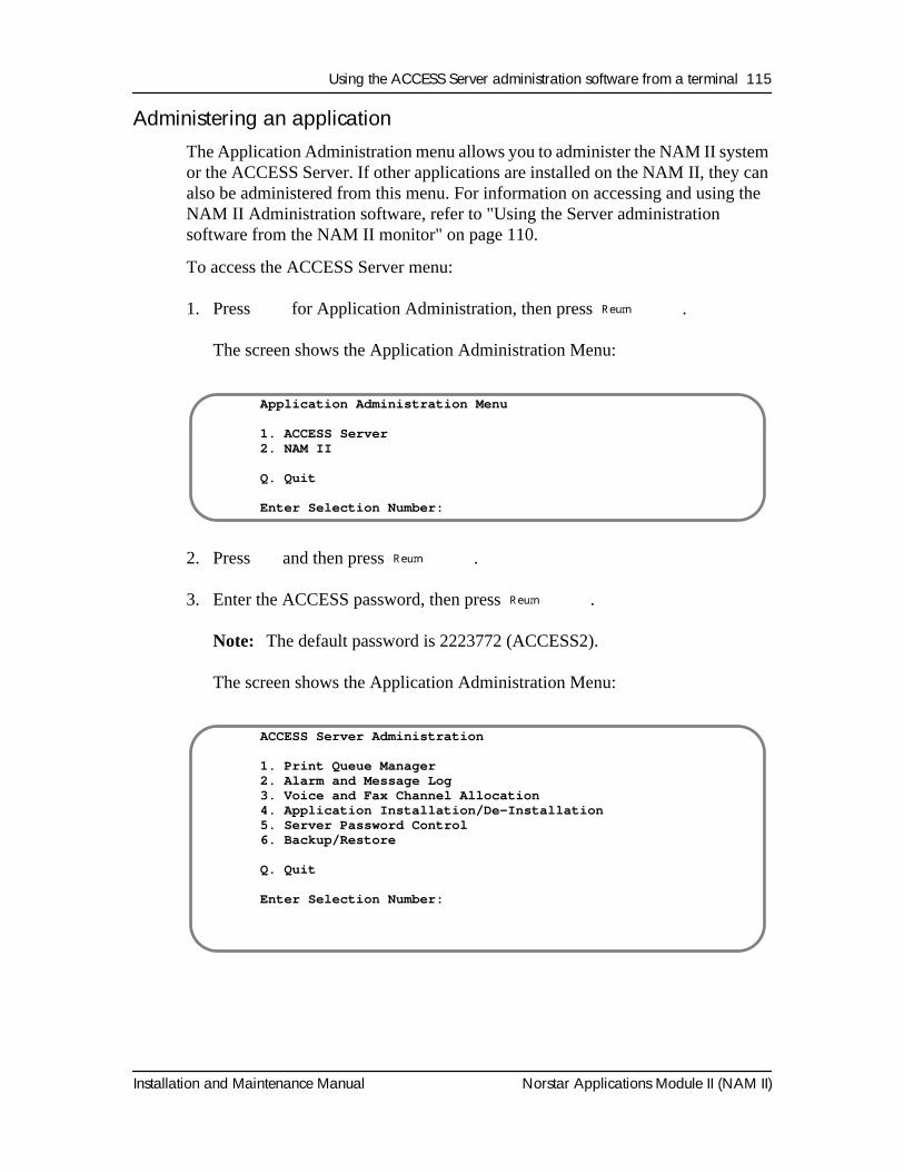
Using the ACCESS Server administration software from a terminal 115
Installation and Maintenance Manual Norstar Applications Module II (NAM II)
Administering an applicationThe Application Administration menu allows you to administer the NAM II system or the ACCESS Server. If other applications are installed on the NAM II, they can also be administered from this menu. For information on accessing and using the NAM II Administration software, refer to "Using the Server administration software from the NAM II monitor" on page 110.
To access the ACCESS Server menu:
1. Press
Ú
for Application Administration, then press
ºReturn
.
The screen shows the Application Administration Menu:
2. Press
Ú
and then press
ºReturn
.
3. Enter the ACCESS password, then press
ºReturn
.
Note:
The default password is 2223772 (ACCESS2).
The screen shows the Application Administration Menu:
Application Administration Menu
1. ACCESS Server2. NAM II
Q. Quit
Enter Selection Number:
ACCESS Server Administration
1. Print Queue Manager2. Alarm and Message Log3. Voice and Fax Channel Allocation4. Application Installation/De-Installation5. Server Password Control6. Backup/Restore
Q. Quit
Enter Selection Number:
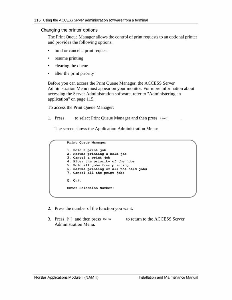
116 Using the ACCESS Server administration software from a terminal
Norstar Applications Module II (NAM II) Installation and Maintenance Manual
Changing the printer optionsThe Print Queue Manager allows the control of print requests to an optional printer and provides the following options:
• hold or cancel a print request
• resume printing
• clearing the queue
• alter the print priority
Before you can access the Print Queue Manager, the ACCESS Server Administration Menu must appear on your monitor. For more information about accessing the Server Administration software, refer to "Administering an application" on page 115.
To access the Print Queue Manager:
1. Press
Ú
to select Print Queue Manager and then press
ºReturn
.
The screen shows the Application Administration Menu:
2. Press the number of the function you want.
3. Press
Œ
and then press
ºReturn
to return to the ACCESS Server Administration Menu.
Print Queue Manager
1. Hold a print job2. Resume printing a held job3. Cancel a print job4. Alter the priority of the jobs5. Hold all jobs from printing6. Resume printing of all the held jobs7. Cancel all the print jobs
Q. Quit
Enter Selection Number:
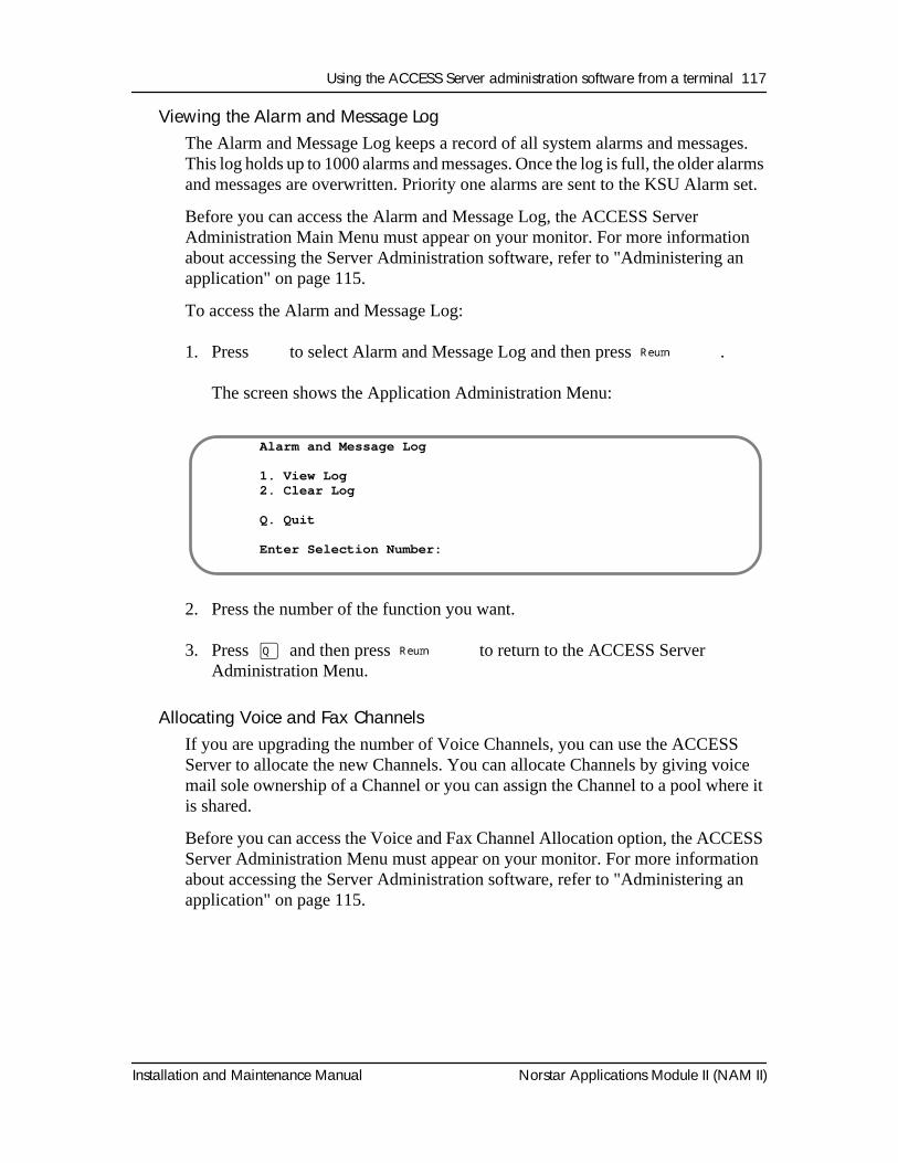
Using the ACCESS Server administration software from a terminal 117
Installation and Maintenance Manual Norstar Applications Module II (NAM II)
Viewing the Alarm and Message LogThe Alarm and Message Log keeps a record of all system alarms and messages. This log holds up to 1000 alarms and messages. Once the log is full, the older alarms and messages are overwritten. Priority one alarms are sent to the KSU Alarm set.
Before you can access the Alarm and Message Log, the ACCESS Server Administration Main Menu must appear on your monitor. For more information about accessing the Server Administration software, refer to "Administering an application" on page 115.
To access the Alarm and Message Log:
1. Press
Û
to select Alarm and Message Log and then press
ºReturn
.
The screen shows the Application Administration Menu:
2. Press the number of the function you want.
3. Press
Œ
and then press
ºReturn
to return to the ACCESS Server Administration Menu.
Allocating Voice and Fax Channels
If you are upgrading the number of Voice Channels, you can use the ACCESS Server to allocate the new Channels. You can allocate Channels by giving voice mail sole ownership of a Channel or you can assign the Channel to a pool where it is shared.
Before you can access the Voice and Fax Channel Allocation option, the ACCESS Server Administration Menu must appear on your monitor. For more information about accessing the Server Administration software, refer to "Administering an application" on page 115.
Alarm and Message Log
1. View Log2. Clear Log
Q. Quit
Enter Selection Number:
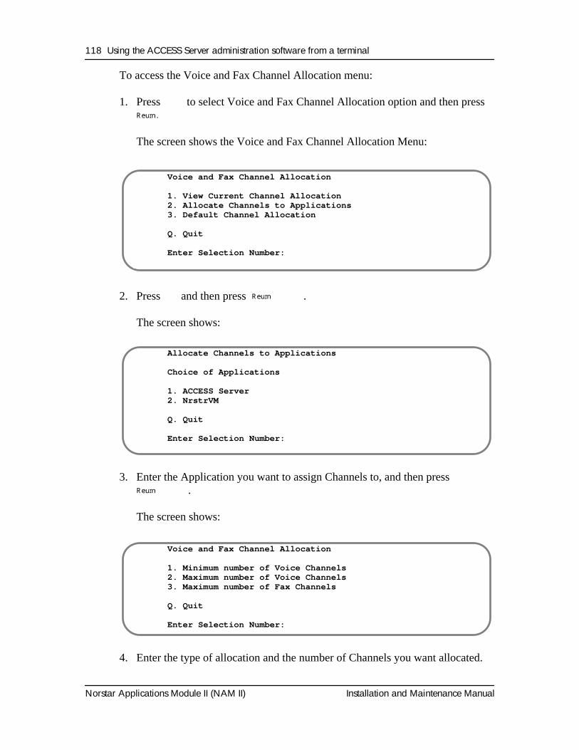
118 Using the ACCESS Server administration software from a terminal
Norstar Applications Module II (NAM II) Installation and Maintenance Manual
To access the Voice and Fax Channel Allocation menu:
1. Press
Ü
to select Voice and Fax Channel Allocation option and then press
ºReturn .
The screen shows the Voice and Fax Channel Allocation Menu:
2. Press
Û
and then press
ºReturn
.
The screen shows:
3. Enter the Application you want to assign Channels to, and then press
ºReturn
.
The screen shows:
4. Enter the type of allocation and the number of Channels you want allocated.
Voice and Fax Channel Allocation
1. View Current Channel Allocation2. Allocate Channels to Applications3. Default Channel Allocation
Q. Quit
Enter Selection Number:
Allocate Channels to Applications
Choice of Applications
1. ACCESS Server2. NrstrVM
Q. Quit
Enter Selection Number:
Voice and Fax Channel Allocation
1. Minimum number of Voice Channels2. Maximum number of Voice Channels3. Maximum number of Fax Channels
Q. Quit
Enter Selection Number:
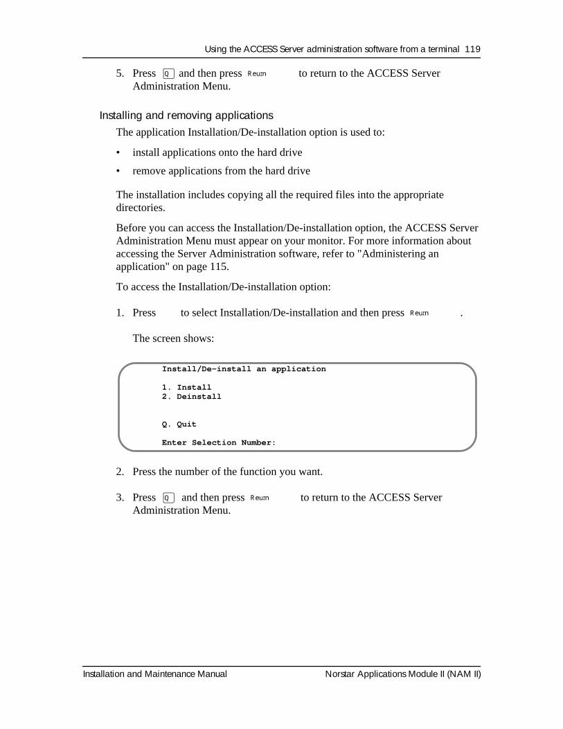
Using the ACCESS Server administration software from a terminal 119
Installation and Maintenance Manual Norstar Applications Module II (NAM II)
5. Press
Œ
and then press
ºReturn
to return to the ACCESS Server Administration Menu.
Installing and removing applications
The application Installation/De-installation option is used to:
• install applications onto the hard drive
• remove applications from the hard drive
The installation includes copying all the required files into the appropriate directories.
Before you can access the Installation/De-installation option, the ACCESS Server Administration Menu must appear on your monitor. For more information about accessing the Server Administration software, refer to "Administering an application" on page 115.
To access the Installation/De-installation option:
1. Press
Ý
to select Installation/De-installation and then press
ºReturn
.
The screen shows:
2. Press the number of the function you want.
3. Press
Œ
and then press
ºReturn
to return to the ACCESS Server Administration Menu.
Install/De-install an application
1. Install2. Deinstall
Q. Quit
Enter Selection Number:
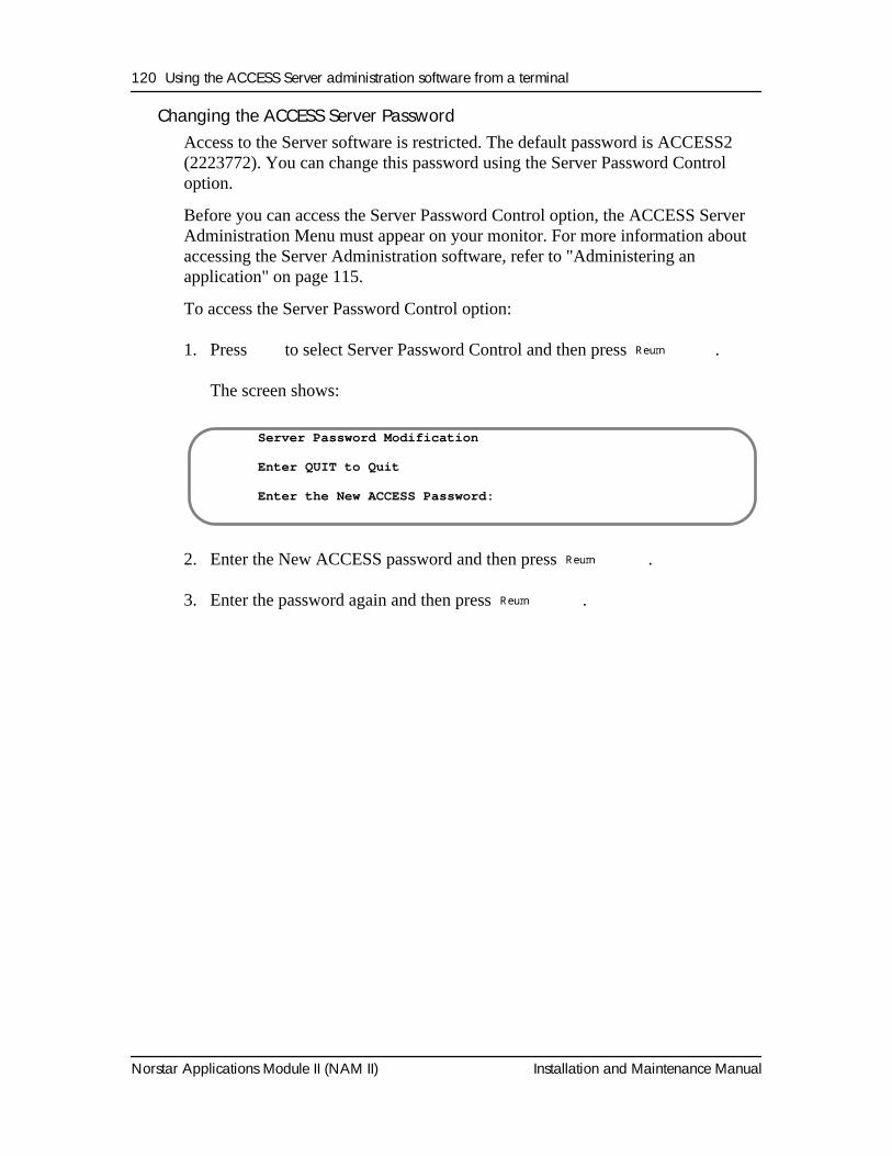
120 Using the ACCESS Server administration software from a terminal
Norstar Applications Module II (NAM II) Installation and Maintenance Manual
Changing the ACCESS Server PasswordAccess to the Server software is restricted. The default password is ACCESS2 (2223772). You can change this password using the Server Password Control option.
Before you can access the Server Password Control option, the ACCESS Server Administration Menu must appear on your monitor. For more information about accessing the Server Administration software, refer to "Administering an application" on page 115.
To access the Server Password Control option:
1. Press
Þ
to select Server Password Control and then press
ºReturn
.
The screen shows:
2. Enter the New ACCESS password and then press
ºReturn
.
3. Enter the password again and then press
ºReturn
.
Server Password Modification
Enter QUIT to Quit
Enter the New ACCESS Password:
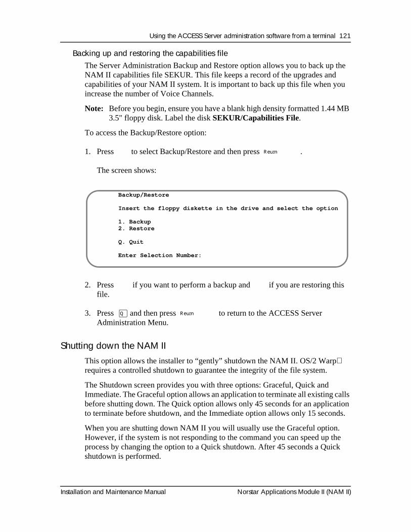
Using the ACCESS Server administration software from a terminal 121
Installation and Maintenance Manual Norstar Applications Module II (NAM II)
Backing up and restoring the capabilities fileThe Server Administration Backup and Restore option allows you to back up the NAM II capabilities file SEKUR. This file keeps a record of the upgrades and capabilities of your NAM II system. It is important to back up this file when you increase the number of Voice Channels.
Note: Before you begin, ensure you have a blank high density formatted 1.44 MB 3.5" floppy disk. Label the disk SEKUR/Capabilities File.
To access the Backup/Restore option:
1. Press
ß
to select Backup/Restore and then press
ºReturn
.
The screen shows:
2. Press
Ú
if you want to perform a backup and
Û
if you are restoring this file.
3. Press
Œ
and then press
ºReturn
to return to the ACCESS Server Administration Menu.
Shutting down the NAM II
This option allows the installer to “gently” shutdown the NAM II. OS/2 Warp
requires a controlled shutdown to guarantee the integrity of the file system.
The Shutdown screen provides you with three options: Graceful, Quick and Immediate. The Graceful option allows an application to terminate all existing calls before shutting down. The Quick option allows only 45 seconds for an application to terminate before shutdown, and the Immediate option allows only 15 seconds.
When you are shutting down NAM II you will usually use the Graceful option. However, if the system is not responding to the command you can speed up the process by changing the option to a Quick shutdown. After 45 seconds a Quick shutdown is performed.
Backup/Restore
Insert the floppy diskette in the drive and select the option
1. Backup2. Restore
Q. Quit
Enter Selection Number:
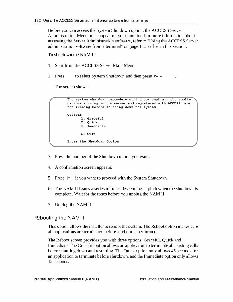
122 Using the ACCESS Server administration software from a terminal
Norstar Applications Module II (NAM II) Installation and Maintenance Manual
Before you can access the System Shutdown option, the ACCESS Server Administration Menu must appear on your monitor. For more information about accessing the Server Administration software, refer to "Using the ACCESS Server administration software from a terminal" on page 113 earlier in this section.
To shutdown the NAM II:
1. Start from the ACCESS Server Main Menu.
2. Press
Ü
to select System Shutdown and then press
ºReturn
.
The screen shows:
3. Press the number of the Shutdown option you want.
4. A confirmation screen appears.
5. Press
Á
if you want to proceed with the System Shutdown.
6. The NAM II issues a series of tones descending in pitch when the shutdown is complete. Wait for the tones before you unplug the NAM II.
7. Unplug the NAM II.
Rebooting the NAM II
This option allows the installer to reboot the system. The Reboot option makes sure all applications are terminated before a reboot is performed.
The Reboot screen provides you with three options: Graceful, Quick and Immediate. The Graceful option allows an application to terminate all existing calls before shutting down and restarting. The Quick option only allows 45 seconds for an application to terminate before shutdown, and the Immediate option only allows 15 seconds.
The system shutdown procedure will check that all the appli-cations running on the server and registered with ACCESS, are not running before shutting down the system.
Options1. Graceful2. Quick3. Immediate
Q. Quit
Enter the Shutdown Option:
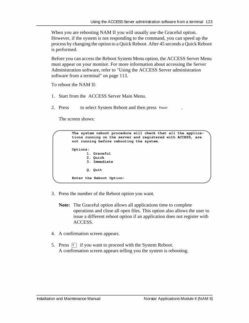
Using the ACCESS Server administration software from a terminal 123
Installation and Maintenance Manual Norstar Applications Module II (NAM II)
When you are rebooting NAM II you will usually use the Graceful option. However, if the system is not responding to the command, you can speed up the process by changing the option to a Quick Reboot. After 45 seconds a Quick Reboot is performed.
Before you can access the Reboot System Menu option, the ACCESS Server Menu must appear on your monitor. For more information about accessing the Server Administration software, refer to "Using the ACCESS Server administration software from a terminal" on page 113.
To reboot the NAM II:
1. Start from the ACCESS Server Main Menu.
2. Press
Ý
to select System Reboot and then press
ºReturn
.
The screen shows:
3. Press the number of the Reboot option you want.
Note:
The Graceful option allows all applications time to complete operations and close all open files. This option also allows the user to issue a different reboot option if an application does not register with ACCESS.
4. A confirmation screen appears.
5. Press
Á
if you want to proceed with the System Reboot.A confirmation screen appears telling you the system is rebooting.
The system reboot procedure will check that all the applica-tions running on the server and registered with ACCESS, are not running before rebooting the system.
Options:1. Graceful2. Quick3. Immediate
Q. Quit
Enter the Reboot Option:
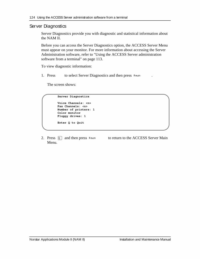
124 Using the ACCESS Server administration software from a terminal
Norstar Applications Module II (NAM II) Installation and Maintenance Manual
Server DiagnosticsServer Diagnostics provide you with diagnostic and statistical information about the NAM II.
Before you can access the Server Diagnostics option, the ACCESS Server Menu must appear on your monitor. For more information about accessing the Server Administration software, refer to "Using the ACCESS Server administration software from a terminal" on page 113.
To view diagnostic information:
1. Press
Û
to select Server Diagnostics and then press
ºReturn
.
The screen shows:
2. Press
Œ
and then press
ºReturn
to return to the ACCESS Server Main Menu.
Server Diagnostics
Voice Channels: <n>Fax Channels: <n>Number of printers: 1Color monitorFloppy drives: 1
Enter Q to Quit
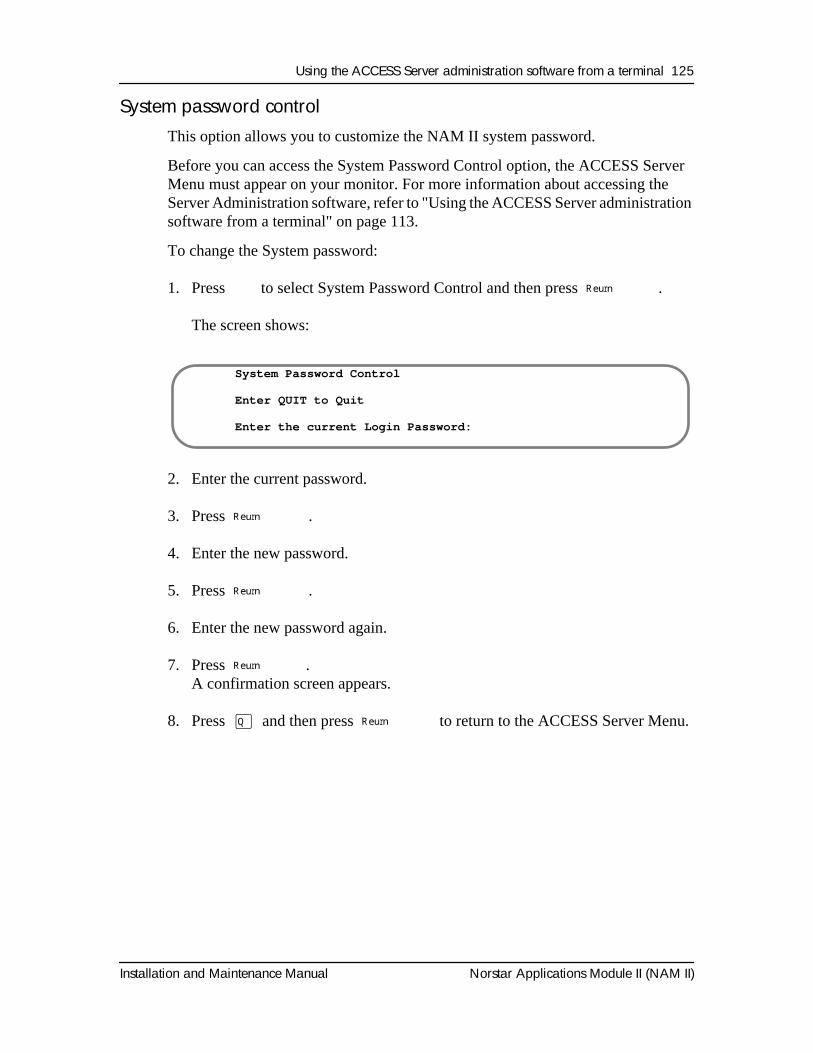
Using the ACCESS Server administration software from a terminal 125
Installation and Maintenance Manual Norstar Applications Module II (NAM II)
System password controlThis option allows you to customize the NAM II system password.
Before you can access the System Password Control option, the ACCESS Server Menu must appear on your monitor. For more information about accessing the Server Administration software, refer to "Using the ACCESS Server administration software from a terminal" on page 113.
To change the System password:
1. Press
Þ
to select System Password Control and then press
ºReturn
.
The screen shows:
2. Enter the current password.
3. Press
º Return
.
4. Enter the new password.
5. Press
º Return
.
6. Enter the new password again.
7. Press
º Return
.A confirmation screen appears.
8. Press
Œ
and then press
ºReturn
to return to the ACCESS Server Menu.
System Password Control
Enter QUIT to Quit
Enter the current Login Password:
126 Using the ACCESS Server administration software from a terminal
Norstar Applications Module II (NAM II) Installation and Maintenance Manual
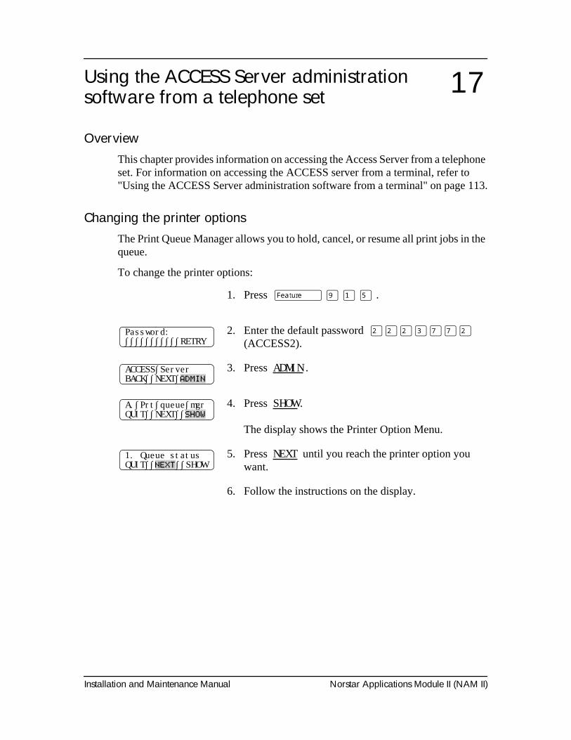
Installation and Maintenance Manual Norstar Applications Module II (NAM II)
Using the ACCESS Server administration software from a telephone set
OverviewThis chapter provides information on accessing the Access Server from a telephone set. For information on accessing the ACCESS server from a terminal, refer to "Using the ACCESS Server administration software from a terminal" on page 113.
Changing the printer optionsThe Print Queue Manager allows you to hold, cancel, or resume all print jobs in the queue.
To change the printer options:
1. Press
ƒ · ⁄ fi
.
2. Enter the default password
¤¤¤‹‡‡¤
(ACCESS2).
3. Press
ADMIN
.
4. Press
SHOW
.
The display shows the Printer Option Menu.
5. Press
NEXT
until you reach the printer option you want.
6. Follow the instructions on the display.
17
Password:∫∫∫∫∫∫∫∫∫∫∫RETRY
ACCESS∫ServerBACK∫∫NEXT∫
ADMIN
A.∫Prt∫queue∫mgrQUIT∫∫NEXT∫∫
SHOW
1. Queue statusQUIT∫∫
NEXT
∫∫SHOW
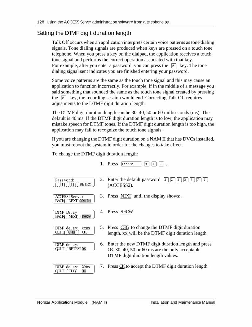
128 Using the ACCESS Server administration software from a telephone set
Norstar Applications Module II (NAM II) Installation and Maintenance Manual
Setting the DTMF digit duration lengthTalk Off occurs when an application interprets certain voice patterns as tone dialing signals. Tone dialing signals are produced when keys are pressed on a touch tone telephone. When you press a key on the dialpad, the application receives a touch tone signal and performs the correct operation associated with that key. For example, after you enter a password, you can press the
£
key. The tone dialing signal sent indicates you are finished entering your password.
Some voice patterns are the same as the touch tone signal and this may cause an application to function incorrectly. For example, if in the middle of a message you said something that sounded the same as the touch tone signal created by pressing the
£
key, the recording session would end. Correcting Talk Off requires adjustments to the DTMF digit duration length.
The DTMF digit duration length can be 30, 40, 50 or 60 milliseconds (ms). The default is 40 ms. If the DTMF digit duration length is to low, the application may mistake speech for DTMF tones. If the DTMF digit duration length is too high, the application may fail to recognize the touch tone signals.
If you are changing the DTMF digit duration on a NAM II that has DVCs installed, you must reboot the system in order for the changes to take effect.
To change the DTMF digit duration length:
1. Press
ƒ · ⁄ fi
.
2. Enter the default password
¤¤¤‹‡‡¤
(ACCESS2).
3. Press
NEXT
until the display shows:.
4. Press
SHOW
.
5. Press
CHG
to change the DTMF digit duration length.
xx
will be the DTMF digit duration length
6. Enter the new DTMF digit duration length and press
OK
. 30, 40, 50 or 60 ms are the only acceptable DTMF digit duration length values.
7. Press
OK
to accept the DTMF digit duration length.
Password:∫∫∫∫∫∫∫∫∫∫∫RETRY
ACCESS∫ServerBACK∫∫NEXT∫
ADMIN
DTMF DelayBACK∫∫NEXT∫∫
SHOW
DTMF delay: xxmsQUIT∫∫
CHG
∫∫ OK
DTMF delay: QUIT ∫RETRY∫
OK
DTMF delay: XXmsQUIT ∫CHG∫
OK
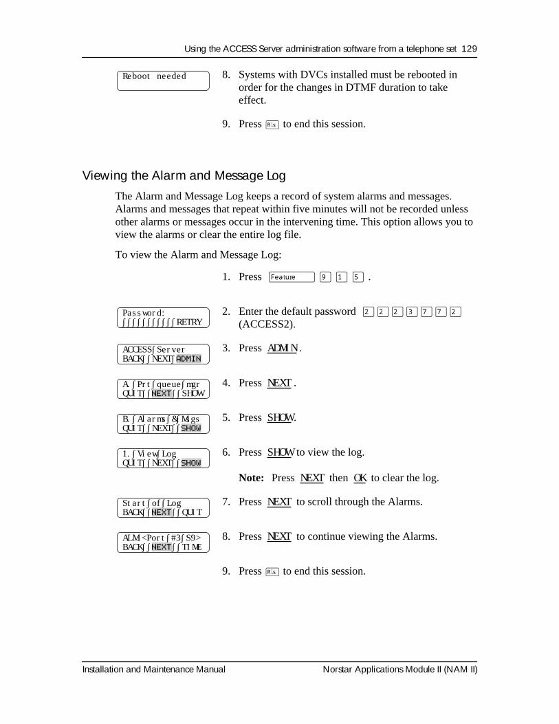
Using the ACCESS Server administration software from a telephone set 129
Installation and Maintenance Manual Norstar Applications Module II (NAM II)
Viewing the Alarm and Message LogThe Alarm and Message Log keeps a record of system alarms and messages. Alarms and messages that repeat within five minutes will not be recorded unless other alarms or messages occur in the intervening time. This option allows you to view the alarms or clear the entire log file.
To view the Alarm and Message Log:
8. Systems with DVCs installed must be rebooted in order for the changes in DTMF duration to take effect.
9. Press
®
to end this session.
1. Press
ƒ · ⁄ fi
.
2. Enter the default password
¤¤¤‹‡‡¤
(ACCESS2).
3. Press
ADMIN
.
4. Press
NEXT
.
5. Press
SHOW
.
6. Press
SHOW
to view the log.
Note:
Press
NEXT
then
OK
to clear the log.
7. Press
NEXT
to scroll through the Alarms.
8. Press
NEXT
to continue viewing the Alarms.
9. Press
®
to end this session.
Reboot needed
Password:∫∫∫∫∫∫∫∫∫∫∫RETRY
ACCESS∫ServerBACK∫∫NEXT∫
ADMIN
A.∫Prt∫queue∫mgrQUIT∫∫
NEXT
∫∫SHOW
B.∫Alarms∫&∫MsgsQUIT∫∫NEXT∫∫
SHOW
1.∫View∫LogQUIT∫∫NEXT∫∫
SHOW
Start∫of∫LogBACK∫∫
NEXT
∫∫QUIT
ALM:<Port∫#3∫S9>BACK∫∫
NEXT
∫∫TIME
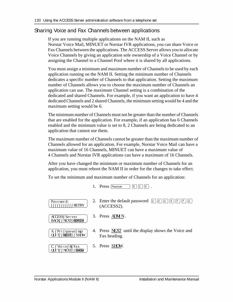
130 Using the ACCESS Server administration software from a telephone set
Norstar Applications Module II (NAM II) Installation and Maintenance Manual
Sharing Voice and Fax Channels between applicationsIf you are running multiple applications on the NAM II, such as Norstar Voice Mail, MINUET or Norstar IVR applications, you can share Voice or Fax Channels between the applications. The ACCESS Server allows you to allocate Voice Channels by giving an application sole ownership of a Voice Channel or by assigning the Channel to a Channel Pool where it is shared by all applications.
You must assign a minimum and maximum number of Channels to be used by each application running on the NAM II. Setting the minimum number of Channels dedicates a specific number of Channels to that application. Setting the maximum number of Channels allows you to choose the maximum number of Channels an application can use. The maximum Channel setting is a combination of the dedicated and shared Channels. For example, if you want an application to have 4 dedicated Channels and 2 shared Channels, the minimum setting would be 4 and the maximum setting would be 6.
The minimum number of Channels must not be greater than the number of Channels that are enabled for the application. For example, if an application has 6 Channels enabled and the minimum value is set to 8, 2 Channels are being dedicated to an application that cannot use them.
The maximum number of Channels cannot be greater than the maximum number of Channels allowed for an application. For example, Norstar Voice Mail can have a maximum value of 16 Channels, MINUET can have a maximum value of 4 Channels and Norstar IVR applications can have a maximum of 16 Channels.
After you have changed the minimum or maximum number of Channels for an application, you must reboot the NAM II in order for the changes to take effect.
To set the minimum and maximum number of Channels for an application:
1. Press
ƒ ·⁄fi
.
2. Enter the default password
¤¤¤‹‡‡¤
(ACCESS2).
3. Press
ADMIN
.
4. Press
NEXT
until the display shows the Voice and Fax heading.
5. Press
SHOW
.
Password:∫∫∫∫∫∫∫∫∫∫∫RETRY
ACCESS∫ServerBACK∫∫NEXT∫
ADMIN
A.∫Prt∫queue∫mgrQUIT∫∫
NEXT
∫∫SHOW
C.∫Voice∫&∫FaxQUIT∫∫NEXT∫∫
SHOW
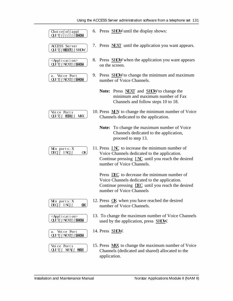
Using the ACCESS Server administration software from a telephone set 131
Installation and Maintenance Manual Norstar Applications Module II (NAM II)
6. Press SHOW
until the display shows:
7. Press
NEXT
until the application you want appears.
8. Press
SHOW
when the application you want appears on the screen.
9. Press
SHOW
to change the minimum and maximum number of Voice Channels.
Note:
Press
NEXT
and
SHOW
to change the minimum and maximum number of Fax Channels and follow steps 10 to 18.
10. Press
MIN
to change the minimum number of Voice Channels dedicated to the application.
Note:
To change the maximum number of Voice Channels dedicated to the application, proceed to step 13.
11. Press
INC
to increase the minimum number of Voice Channels dedicated to the application. Continue pressing
INC
until you reach the desired number of Voice Channels.
Press
DEC
to decrease the minimum number of Voice Channels dedicated to the application. Continue pressing
DEC
until you reach the desired number of Voice Channels
12. Press
OK
when you have reached the desired number of Voice Channels.
13. To change the maximum number of Voice Channels used by the application, press
SHOW
.
14. Press
SHOW
.
15. Press
MAX
to change the maximum number of Voice Channels (dedicated and shared) allocated to the application.
Choice∫of∫applQUIT∫∫∫∫∫∫∫∫
SHOW
ACCESS ServerQUIT∫∫
NEXT
∫∫SHOW
<Application>QUIT∫∫NEXT∫∫
SHOW
a. Voice PortQUIT∫∫NEXT∫∫
SHOW
Voice PortsQUIT∫∫
MIN
∫∫ MAX
Min ports:XDEC∫∫ INC∫∫ OK
Min ports:XDEC∫∫ INC∫∫
OK
<Application>QUIT∫∫NEXT∫∫
SHOW
a. Voice PortQUIT∫∫NEXT∫∫
SHOW
Voice PortsQUIT∫∫ MIN∫∫
MAX
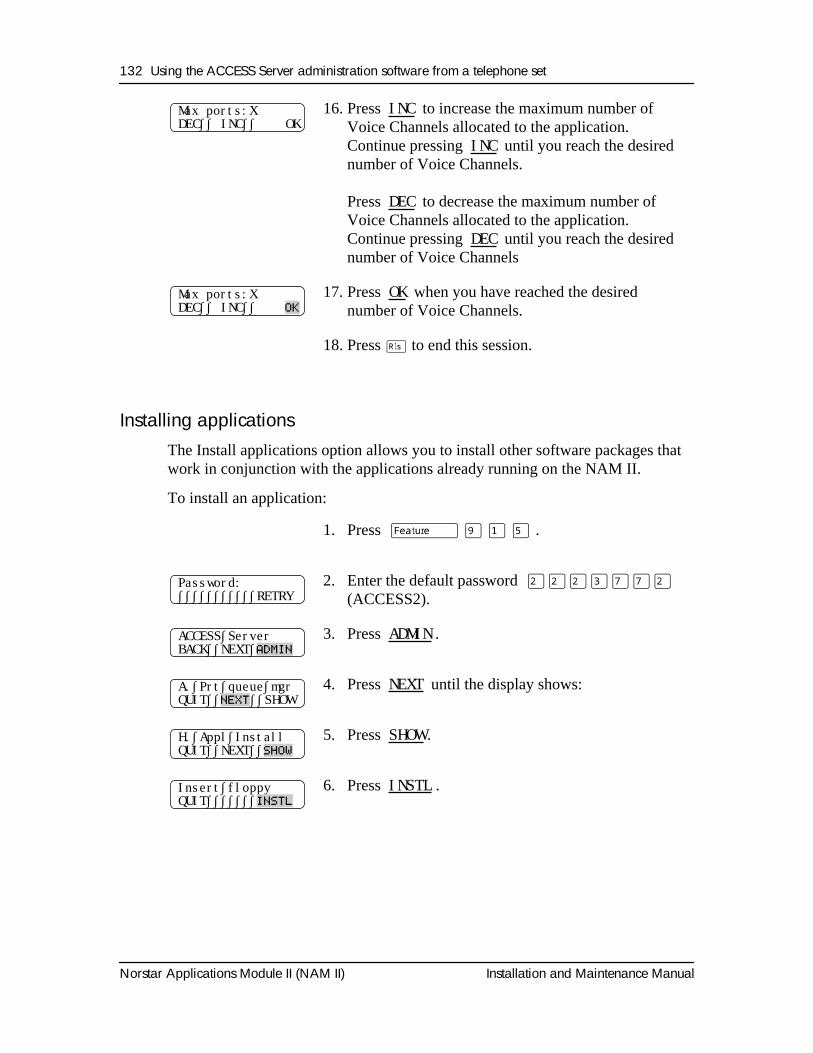
132 Using the ACCESS Server administration software from a telephone set
Norstar Applications Module II (NAM II) Installation and Maintenance Manual
Installing applicationsThe Install applications option allows you to install other software packages that work in conjunction with the applications already running on the NAM II.
To install an application:
16. Press INC
to increase the maximum number of Voice Channels allocated to the application. Continue pressing
INC
until you reach the desired number of Voice Channels.
Press
DEC
to decrease the maximum number of Voice Channels allocated to the application. Continue pressing
DEC
until you reach the desired number of Voice Channels
17. Press
OK
when you have reached the desired number of Voice Channels.
18. Press
®
to end this session.
1. Press
ƒ · ⁄ fi
.
2. Enter the default password
¤¤¤‹‡‡¤
(ACCESS2).
3. Press
ADMIN
.
4. Press
NEXT
until the display shows:
5. Press
SHOW
.
6. Press
INSTL
.
Max ports:XDEC∫∫ INC∫∫ OK
Max ports:XDEC∫∫ INC∫∫
OK
Password:∫∫∫∫∫∫∫∫∫∫∫RETRY
ACCESS∫ServerBACK∫∫NEXT∫
ADMIN
A.∫Prt∫queue∫mgrQUIT∫∫
NEXT
∫∫SHOW
H.∫Appl∫InstallQUIT∫∫NEXT∫∫
SHOW
Insert∫floppyQUIT∫∫∫∫∫∫∫
INSTL
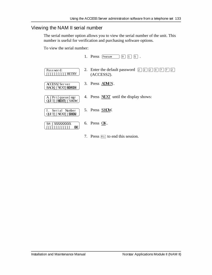
Using the ACCESS Server administration software from a telephone set 133
Installation and Maintenance Manual Norstar Applications Module II (NAM II)
Viewing the NAM II serial numberThe serial number option allows you to view the serial number of the unit. This number is useful for verification and purchasing software options.
To view the serial number:
1. Press
ƒ · ⁄ fi
.
2. Enter the default password
¤¤¤‹‡‡¤
(ACCESS2).
3. Press
ADMIN
.
4. Press
NEXT
until the display shows:
5. Press
SHOW
.
6. Press
OK
.
7. Press
®
to end this session.
Password:∫∫∫∫∫∫∫∫∫∫∫RETRY
ACCESS∫ServerBACK∫∫NEXT∫
ADMIN
A.∫Prt∫queue∫mgrQUIT∫∫
NEXT
∫∫SHOW
I. Serial NumberQUIT∫∫NEXT∫∫
SHOW
S#:∫XXXXXXXXX∫∫∫∫∫∫∫∫∫∫∫∫∫
OK
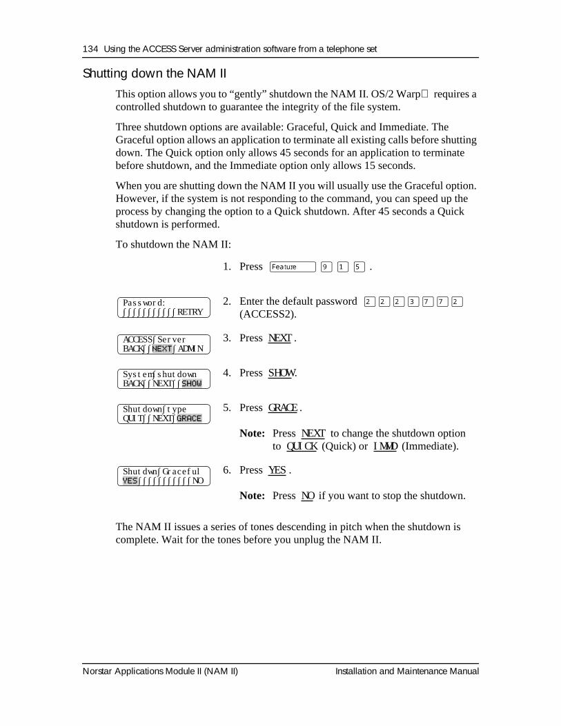
134 Using the ACCESS Server administration software from a telephone set
Norstar Applications Module II (NAM II) Installation and Maintenance Manual
Shutting down the NAM IIThis option allows you to “gently” shutdown the NAM II. OS/2 Warp requires a controlled shutdown to guarantee the integrity of the file system.
Three shutdown options are available: Graceful, Quick and Immediate. The Graceful option allows an application to terminate all existing calls before shutting down. The Quick option only allows 45 seconds for an application to terminate before shutdown, and the Immediate option only allows 15 seconds.
When you are shutting down the NAM II you will usually use the Graceful option. However, if the system is not responding to the command, you can speed up the process by changing the option to a Quick shutdown. After 45 seconds a Quick shutdown is performed.
To shutdown the NAM II:
The NAM II issues a series of tones descending in pitch when the shutdown is complete. Wait for the tones before you unplug the NAM II.
1. Press
ƒ · ⁄ fi
.
2. Enter the default password
¤¤¤‹‡‡¤
(ACCESS2).
3. Press
NEXT
.
4. Press
SHOW
.
5. Press
GRACE
.
Note:
Press
NEXT
to change the shutdown option to
QUICK
(Quick) or
IMMD
(Immediate).
6. Press
YES
.
Note:
Press
NO
if you want to stop the shutdown.
Password:∫∫∫∫∫∫∫∫∫∫∫RETRY
ACCESS∫ServerBACK∫∫
NEXT
∫ADMIN
System∫shutdownBACK∫∫NEXT∫∫
SHOW
Shutdown∫typeQUIT∫∫NEXT∫
GRACE
Shutdwn∫Graceful
YES
∫∫∫∫∫∫∫∫∫∫∫NO
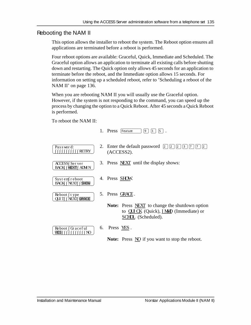
Using the ACCESS Server administration software from a telephone set 135
Installation and Maintenance Manual Norstar Applications Module II (NAM II)
Rebooting the NAM IIThis option allows the installer to reboot the system. The Reboot option ensures all applications are terminated before a reboot is performed.
Four reboot options are available: Graceful, Quick, Immediate and Scheduled. The Graceful option allows an application to terminate all existing calls before shutting down and restarting. The Quick option only allows 45 seconds for an application to terminate before the reboot, and the Immediate option allows 15 seconds. For information on setting up a scheduled reboot, refer to ’Scheduling a reboot of the NAM II’ on page 136.
When you are rebooting NAM II you will usually use the Graceful option. However, if the system is not responding to the command, you can speed up the process by changing the option to a Quick Reboot. After 45 seconds a Quick Reboot is performed.
To reboot the NAM II:
1. Press
ƒ · ⁄ fi
.
2. Enter the default password
¤¤¤‹‡‡¤
(ACCESS2).
3. Press
NEXT
until the display shows:
4. Press
SHOW
.
5. Press
GRACE
.
Note:
Press
NEXT
to change the shutdown option to
QUICK
(Quick),
IMMD
(Immediate) or
SCHDL
(Scheduled).
6. Press
YES
.
Note:
Press
NO
if you want to stop the reboot.
Password:∫∫∫∫∫∫∫∫∫∫∫RETRY
ACCESS∫ServerBACK∫∫
NEXT
∫ADMIN
System∫rebootBACK∫∫NEXT∫∫
SHOW
Reboot∫typeQUIT∫∫NEXT∫
GRACE
Reboot∫Graceful
YES
∫∫∫∫∫∫∫∫∫∫∫NO
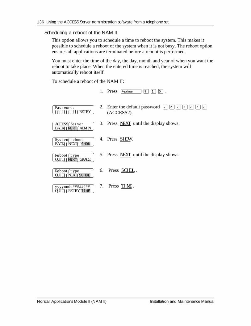
136 Using the ACCESS Server administration software from a telephone set
Norstar Applications Module II (NAM II) Installation and Maintenance Manual
Scheduling a reboot of the NAM IIThis option allows you to schedule a time to reboot the system. This makes it possible to schedule a reboot of the system when it is not busy. The reboot option ensures all applications are terminated before a reboot is performed.
You must enter the time of the day, the day, month and year of when you want the reboot to take place. When the entered time is reached, the system will automatically reboot itself.
To schedule a reboot of the NAM II:
1. Press
ƒ · ⁄ fi
.
2. Enter the default password
¤¤¤‹‡‡¤
(ACCESS2).
3. Press
NEXT
until the display shows:
4. Press
SHOW
.
5. Press
NEXT
until the display shows:
6. Press
SCHDL
.
7. Press
TIME
.
Password:∫∫∫∫∫∫∫∫∫∫∫RETRY
ACCESS∫ServerBACK∫∫
NEXT
∫ADMIN
System∫rebootBACK∫∫NEXT∫∫
SHOW
Reboot∫typeQUIT∫∫
NEXT
∫GRACE
Reboot∫typeQUIT∫∫NEXT∫
SCHDL
yyyymmdd########QUIT∫∫RETRY∫
TIME
Installation and Maintenance Manual Norstar Applications Module II (NAM II)
Section V - Troubleshooting
• Troubleshooting

138 Troubleshooting
Norstar Applications Module II (NAM II) Installation and Maintenance Manual
Installation and Maintenance Manual Norstar Applications Module II (NAM II)
Troubleshooting
OverviewTroubleshooting NAM II problems involves determining the symptoms and diagnosing the cause of the problem.
A problem can be the result of more than one component failure. Diagnosing a NAM II problem involves isolating the cause, and determining whether or not the malfunction involves a failed hardware component.
After you have determined the cause of the problem, and corrected the problem by replacing a component, you must test the NAM II to determine whether or not it is working properly.
18
140 Troubleshooting
Norstar Applications Module II (NAM II) Installation and Maintenance Manual
Diagnosing problemsA malfunctioning NAM II can be caused by a faulty component. This section describes the symptoms that occur when the NAM II malfunctions. The section describes symptoms particular to hardware. The symptoms are described first, followed by procedures to confirm and correct the problem.
Hardware problemsHardware problems appear as any of the following:
• NAM II does not function at all
• The Power-on diagnostics fail
• The Power-on diagnostics run, but the download diagnostics do not
• NAM II Digital Voice Cards (DVCs) are not functioning properly
Note: The procedures describe the components in the order of the most likely to cause the trouble.
The NAM II does not function at all
If there is no response from the NAM II or the Feature Codes do not appear on the Norstar display:
1. Make sure the:
• AC power cord is plugged in
• NAM II is getting power from the AC outlet
Note: When the power is connected, the fan works.
2. Unplug the NAM II and remove the front cover. Reseat the DVC(s). Check to ensure all ribbon cable and power supply connectors are properly connected.
3. Reseat the SBC located in slot 4. Check to ensure all ribbon cables are connected to the SBC.
4. Replace the front cover and plug in the NAM II.
CAUTION
Before attempting any repair procedures that require replacing internal components, attach one end of your grounding strap to your wrist and the other end to the NAM II.
Troubleshooting 141
Installation and Maintenance Manual Norstar Applications Module II (NAM II)
Digital Voice Cards are not functioning properly
1. Check the setting of Auto Set Relocation on the Norstar System. Set it to Off. Refer to the Norstar Installation Guide for instructions.
2. Unplug the NAM II and open the module door. Remove the two screws holding the front cover to the module. The screws are located along the top of the front cover. Slide the front cover out from the module.
3. Ensure that each card is securely seated in its expansion bus slot.
4. Disconnect the Teladapt cord from a DVC Channel.
5. Plug the free cord end into a Norstar telephone. Press
Ä • ‚
to determine the Channel number connected to Norstar Voice Mail. If the cord and Norstar Channel are working properly, a number should appear. Write down the Channel number and the corresponding Teladapt jack number.
6. Reconnect the Teladapt cord to the module.
7. Repeat this procedure, beginning at step 4, for each DVC Channel.
8. If a teladapt jack is not working, check for loose connections or broken wires. Ensure the problem is not with the teladapt cord. Using a cord you know works, connect the telephone and the jack to the KSU. If neither the wiring nor the cord is the problem, the KSU needs repair.
If the teladapt jacks are working, you must identify which of the DVC Channels are not working. Continuing from step 7:
9. Plug in the NAM II and give it time to complete the diagnostics.
10. Establish a Norstar Maintenance session. From a Norstar telephone connected to the KSU, access:
D. Maintenance
and
2. Port DN Status
Refer to the
Norstar Installation Guide
for instructions.
11. Display the type and state of the Channel connected to each of the Norstar teladapt jacks. Verify the Channel numbers with the ones you wrote down when you tested the jacks in step 5.
142 Troubleshooting
Norstar Applications Module II (NAM II) Installation and Maintenance Manual
Each Channel should show PCID as the device type. If any Channel numbers connected to Norstar Voice Mail show NONE as the device type, it indicates the DVC is not working.
Note: You can also use an M7324 set to display the working Norstar Voice Mail Channels. After you have identified which Channels are not appearing in the Channel/DN Status display, trace the teladapt cords from the teladapt jacks to the Applications Module. This shows you which DVC is not working.
If any DVCs are identified as not working:
12. Verify the DVC Switch and Jumper settings. Refer to "Installing the second, third or fourth DVC" on page 52.
13. Replace the DVCs and retest the DVC Channels. Refer to "Installing and upgrading the Digital Voice Cards (DVC)s" on page 51.
14. If the NAM II is attached to a Centrex KSU, make sure all Channels are defined as Norstar only.
Checking the Channel StatusChecking the Channel Status allows you to check each Channel for the following:
• If the Channel is installed
• If the Channel is idle
• If the Channel is currently receiving or dialing a call
• If the Channel is connected to a call
• If the Channel is connected to the KSU, but no application using the Channel
• If the Channel is available, but has been not connected to the KSU
• Disable or re-enable a Channel
Note: Channel Status will show the status for all Channels. Channel Status will not identify the Channels as Voice or Fax*.
*Fax Channels are only available on systems with Norstar Voice Mail FAX installed.
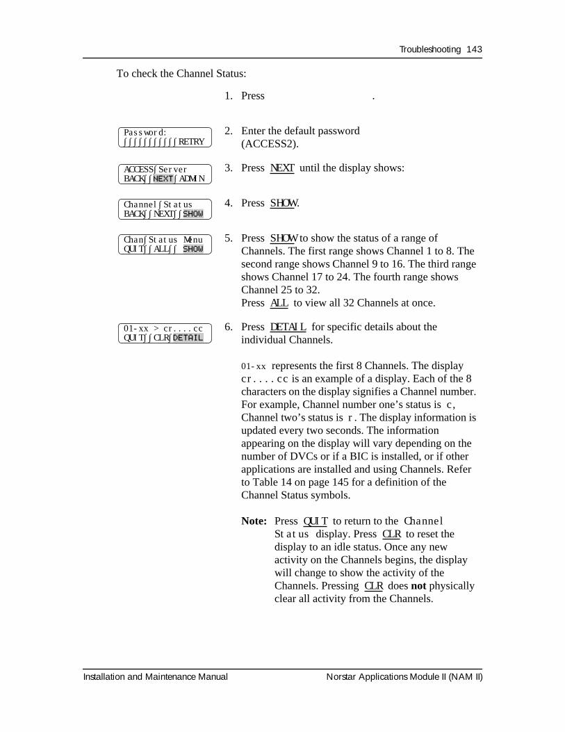
Troubleshooting 143
Installation and Maintenance Manual Norstar Applications Module II (NAM II)
To check the Channel Status:
1. Press
Ä á Ú Þ
.
2. Enter the default password
ÛÛÛÜààÛ
(ACCESS2).
3. Press
NEXT
until the display shows:
4. Press
SHOW
.
5. Press
SHOW
to show the status of a range of Channels. The first range shows Channel 1 to 8. The second range shows Channel 9 to 16. The third range shows Channel 17 to 24. The fourth range shows Channel 25 to 32. Press
ALL
to view all 32 Channels at once.
6. Press
DETAIL
for specific details about the individual Channels.
01-xx
represents the first 8 Channels. The display
cr....cc
is an example of a display. Each of the 8 characters on the display signifies a Channel number. For example, Channel number one’s status is
c
, Channel two’s status is
r
. The display information is updated every two seconds. The information appearing on the display will vary depending on the number of DVCs or if a BIC is installed, or if other applications are installed and using Channels. Refer to Table 14 on page 145 for a definition of the Channel Status symbols.
Note:
Press
QUIT
to return to the
Channel Status
display. Press
CLR
to reset the display to an idle status. Once any new activity on the Channels begins, the display will change to show the activity of the Channels. Pressing
CLR
does
not
physically clear all activity from the Channels.
Password:∫∫∫∫∫∫∫∫∫∫∫RETRY
ACCESS∫ServerBACK∫∫
NEXT
∫ADMIN
Channel∫StatusBACK∫∫NEXT∫∫
SHOW
Chan∫Status MenuQUIT∫∫ALL∫∫
SHOW
01-xx > cr....ccQUIT∫∫CLR∫
DETAIL
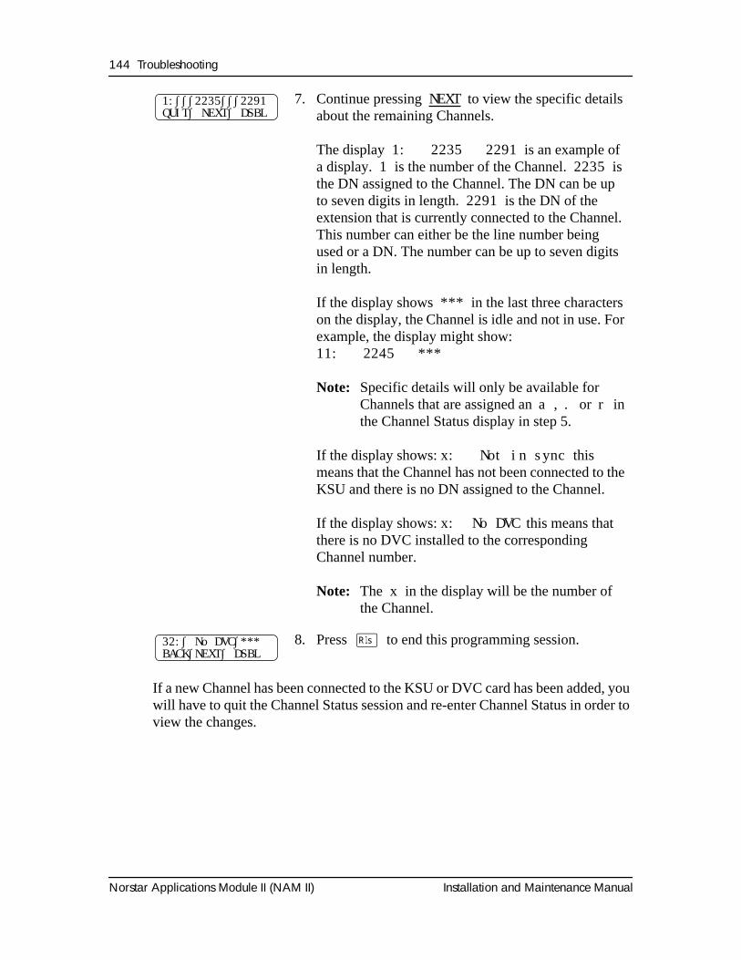
144 Troubleshooting
Norstar Applications Module II (NAM II) Installation and Maintenance Manual
If a new Channel has been connected to the KSU or DVC card has been added, you will have to quit the Channel Status session and re-enter Channel Status in order to view the changes.
7. Continue pressing NEXT
to view the specific details about the remaining Channels.
The display
1: 2235 2291
is an example of a display.
1
is the number of the Channel.
2235
is the DN assigned to the Channel. The DN can be up to seven digits in length.
2291
is the DN of the extension that is currently connected to the Channel. This number can either be the line number being used or a DN. The number can be up to seven digits in length.
If the display shows
***
in the last three characters on the display, the Channel is idle and not in use. For example, the display might show:
11: 2245 ***
Note:
Specific details will only be available for Channels that are assigned an
a
,
.
or
r
in the Channel Status display in step 5.
If the display shows:
x: Not in sync
this means that the Channel has not been connected to the KSU and there is no DN assigned to the Channel.
If the display shows:
x: No DVC
this means that there is no DVC installed to the corresponding Channel number.
Note:
The
x
in the display will be the number of the Channel.
8. Press
®
to end this programming session.
1:∫∫∫2235∫∫∫2291QUIT∫ NEXT∫ DSBL
32:∫ No DVC∫***BACK∫NEXT∫ DSBL
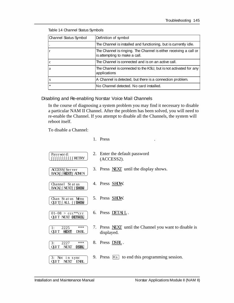
Troubleshooting 145
Installation and Maintenance Manual Norstar Applications Module II (NAM II)
Table 14 Channel Status Symbols
Disabling and Re-enabling Norstar Voice Mail ChannelsIn the course of diagnosing a system problem you may find it necessary to disable a particular NAM II Channel. After the problem has been solved, you will need to re-enable the Channel. If you attempt to disable all the Channels, the system will reboot itself.
To disable a Channel:
Channel Status Symbol Definition of symbol
. The Channel is installed and functioning, but is currently idle.
r The Channel is ringing. The Channel is either receiving a call or is attempting to make a call.
c The Channel is connected and is on an active call.
a The Channel is connected to the KSU, but is not activated for any applications
x A Channel is detected, but there is a connection problem.
* No Channel detected. No card installed.
1. Press
Ä á Ú Þ
.
2. Enter the default password
ÛÛÛÜààÛ
(ACCESS2).
3. Press
NEXT
until the display shows.
4. Press
SHOW
.
5. Press
SHOW
.
6. Press
DETAIL
.
7. Press
NEXT
until the Channel you want to disable is displayed.
8. Press
DSBL
.
9. Press
®
to end this programming session.
Password:∫∫∫∫∫∫∫∫∫∫∫RETRY
ACCESS∫ServerBACK∫∫
NEXT
∫ADMIN
Channel StatusBACK∫∫NEXT∫∫
SHOW
Chan Status MenuQUIT∫∫ALL ∫∫
SHOW
01-08 > ccc**crrQUIT NEXT
DETAIL
1: 2225 ***QUIT
NEXT
DSBL
3: 2227 ***QUIT NEXT
DSBL
3: Not in syncQUIT NEXT ENBL
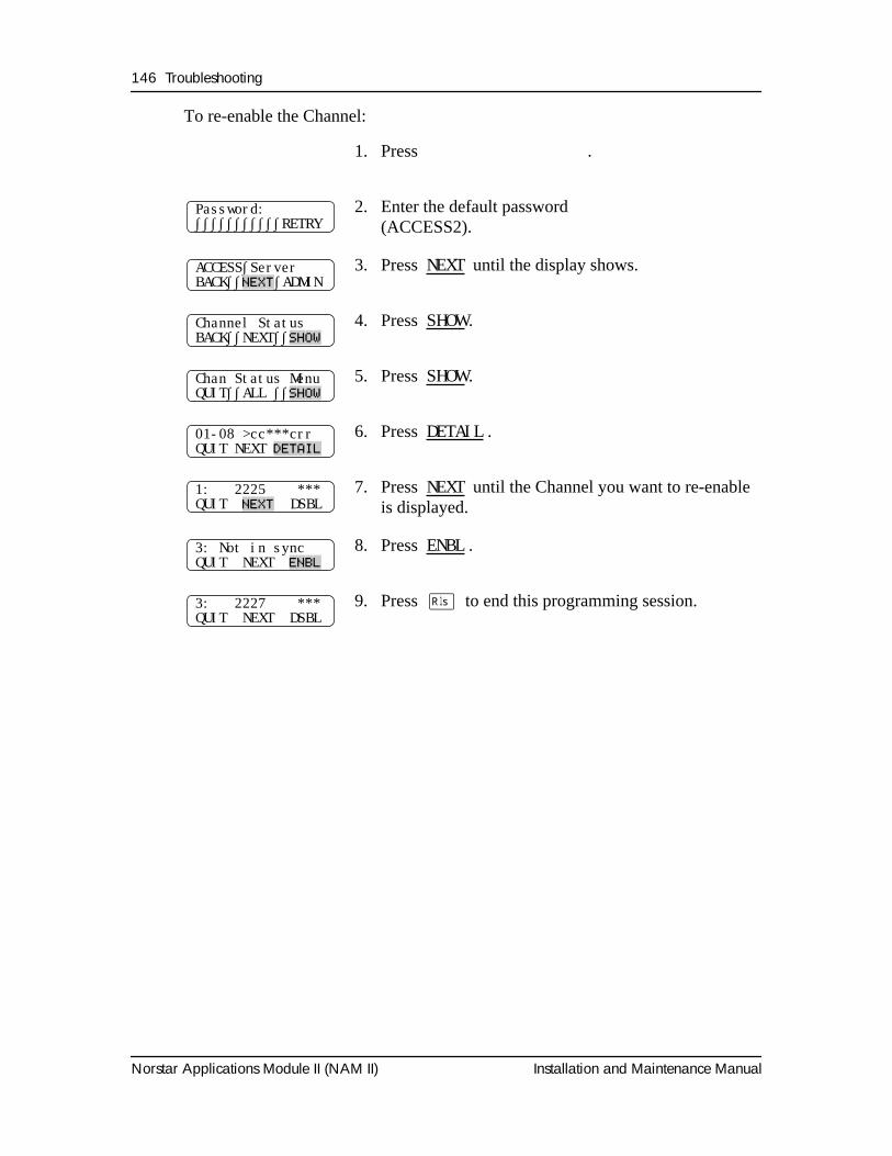
146 Troubleshooting
Norstar Applications Module II (NAM II) Installation and Maintenance Manual
To re-enable the Channel:
1. Press
Ä á Ú Þ
.
2. Enter the default password
ÛÛÛÜààÛ
(ACCESS2).
3. Press
NEXT
until the display shows.
4. Press
SHOW
.
5. Press
SHOW
.
6. Press
DETAIL
.
7. Press
NEXT
until the Channel you want to re-enable is displayed.
8. Press
ENBL
.
9. Press
®
to end this programming session.
Password:∫∫∫∫∫∫∫∫∫∫∫RETRY
ACCESS∫ServerBACK∫∫
NEXT
∫ADMIN
Channel StatusBACK∫∫NEXT∫∫
SHOW
Chan Status MenuQUIT∫∫ALL ∫∫
SHOW
01-08 >cc***crrQUIT NEXT
DETAIL
1: 2225 ***QUIT
NEXT
DSBL
3: Not in syncQUIT NEXT
ENBL
3: 2227 ***QUIT NEXT DSBL
Troubleshooting 147
Installation and Maintenance Manual Norstar Applications Module II (NAM II)
Preparing the NAM II for travelPerform the following if you are returning the NAM II to the factory for service or are mounting it in a new location.
1. Shutdown the NAM II. For more information, refer to "Shutting down the NAM II" on page 29.
2. Remove the NAM II power cord from the AC outlet.
3. Unplug the station Channel(s) from the DVC(s) on the module and disconnect any other cabling or wiring to the module.
4. Remove the two screws in the cable trough.
5. Grasp the module on its sides and gently lift straight up until the module is clear of the wall-mounting bracket.
6. If you are returning the NAM II for service, pack it in its original shipping container. If the container is not available, package the module well with plenty of shock-absorbing, insulating material.
148 Troubleshooting
Norstar Applications Module II (NAM II) Installation and Maintenance Manual
Installation and Maintenance Manual Norstar Applications Module II (NAM II)
Glossary
AMIS
Audio Messaging Interchange Specification (AMIS) provides voice messaging to different mailboxes located at different sites on a communication network.
Application
A computer program that performs a wide range of tasks as specified by the user. Examples of application programs include word processing packages, spreadsheet packages and accounting packages.
Backplane
The backplane hosts the SBC and all other cards inserted in the NAM II. The backplane connects the wiring between all circuits.
Back up
To make a duplicate copy of data files so that you can store the originals in a safe place. Backing up your original files protects them from damage if a hardware failure occurs.
Baud rate
A unit of measurement of data transmission speed. It is approximately equivalent to Bits Per Second (BPS). Typical baud rates are 300, 1200, 2400, 4800, and 9600.
Bit
An abbreviation for Binary Digit. A bit is the smallest unit of information recognized by the computer. A bit has one of two values (0 or 1) to indicate off or on.
BIOS (Basic Input Output System)
A program contained in Read Only Memory (ROM) that acts as the interface between software programs and the computer hardware.
BPS (Bits Per Second)
The speed of data transmission between two computers.
Bus
A collection of communication lines that carry electronic signals either between elements on the system board or between the circuitry on the system board and any cards plugged into the system board.
Byte
The amount of space required to store a single character. One byte equals eight bits.
150 Glossary
Norstar Applications Module II (NAM II) Installation and Maintenance Manual
CD-ROM (Compact Disc Read Only Memory)
The CD-ROM drive and the accompanying CD-ROM disk are used to upgrade the system software.
Conventions
The way certain information is described. For example, using underlined text to represent second-line display prompt information.
Default
The parameters that are preset within the NAM II.
Disk drive
A mass storage device that seeks, reads and writes data on a disk.
Diskette
A removable magnetic disk used to store data.
Display
A one-line or two-line screen on a Norstar telephone that shows commands and options.
Display buttons
The three buttons that appear underneath Norstar two-line LCD display.
Display options
The choices available to a user that appear on the Norstar two-line display. Options appearing on the display can be selected using the display or dialpad buttons.
Extended Data-Out (EDO)
Extended Data-Out (EDO) is a form of Dynamic Random Access Memory (RAM) in which storing data to and reading data from the memory is performed at a faster rate.
FAX
FAX works with Norstar Voice Mail and Norstar, offering a caller the capability of sending a fax document to a mailbox as easily as sending a voice message.
Feature Code
A unique three-digit code used to access NAM II Features and options.
File
A collection of related information stored on a disk under a given name for later reference and used by an operating system or application program. Each application program that you use saves the data you create in files. Files are identified by a file name and optional extension.
Glossary 151
Installation and Maintenance Manual Norstar Applications Module II (NAM II)
File name
A name that identifies a file and consists of one to eight characters.
Hard disk drive
A data storage device that uses non-removable, rigid magnetic platters. Hard disk drives work faster and store more data than disk drives do for diskettes.
Hardware
The physical components of the NAM II.
Hz (hertz)
A unit of measure for indicating frequency in cycles per second.
Initialization
The steps required to prepare hardware or software for operation.
Install
To set up for operation. For example, hardware is installed by attaching it to the appropriate connectors or sockets either inside or outside the NAM II.
Interface
An information interchange path that allows communication between computer parts.
Interleave
The number of hard drive revolutions required to read from or write to one entire track of data. For example, a 3:1 interleave requires three revolutions to read from or write to an entire track of data; a 1:1 interleave requires only one complete disk revolution to read from or write to an entire track of data. The lower the ratio, the faster the read/write operation.
IRQ (Interrupt Request)
A signal sent by a hardware device to the microprocessor requesting its immediate attention. For example, each communications port has an interrupt request line for notifying the microprocessor when data has been received or transmitted.
Kbyte
The abbreviation for kilobyte. A kilobyte is equal to 1024 bytes.
Mailbox
A storage place for messages on the Norstar Voice Mail system.
Mbyte
The abbreviation for megabyte. A megabyte is equal to 1,048,576 bytes. Megabyte is also abbreviated as MB.
152 Glossary
Norstar Applications Module II (NAM II) Installation and Maintenance Manual
MHz
The abbreviation for megahertz. This is a unit of measure indicating frequency in millions of cycles per second.
Microprocessor
A chip that is the center of all activity inside the Applications Module. The microprocessor controls all logical and arithmetic operations for the computer and is responsible for executing program commands. It is also referred to as the Central Processing Unit (CPU).
Modem
A communications device that allows data to be exchanged between computers over telephone lines. The exchange is done by electronic processes called modulation and demodulation. The modem changes (modulates) the data into tones to send to another modem and also converts (demodulates) tones when receiving from another modem.
M7100 telephone
The Norstar model M7100 telephone that has a single-line display and one programmable button without an indicator.
M7208 telephone
The Norstar model M7208 telephone that has a single-line display and eight programmable buttons with indicators.
M7310 telephone
The Norstar model M7310 telephone that has a two-line display with three display buttons, 10 programmable buttons with indicators and 12 dual programmable buttons without indicators.
M7324 telephone
The Norstar model M7324 telephone that has a two-line display with three display buttons and 24 programmable buttons with indicators.
Network
Two or more computers linked together electronically to share programs and exchange data. Joining computers over a network requires adding specialized hardware and software to each computer.
Operating system
The disk-based software that manages the operation of the Applications Module. An operating system controls the flow of information between the computer hardware such as the keyboard, video display, disk drives and printer. IBM OS/2 is the operating system that manages the Applications Module.
Glossary 153
Installation and Maintenance Manual Norstar Applications Module II (NAM II)
Option
A NAM II choice that is given to a user through display prompts.
Parallel port
A port that transfers data through multiple wires so that eight bits are transmitted simultaneously. Parallel ports usually use a 25-pin interface that transmits and receives data one byte at a time using a separate data line for each bit.
Password
A four-digit to eight-digit number that is entered using the dialpad. A password is used to open mailboxes or perform configuration tasks.
PEB (PCM Expansion Bus)
A PEB cable is used to connect the Digital Voice Cards (DVCs) to the Digital Fax Card (DFC) when the FAX option is installed.
Peripheral
A device that is connected to and communicates with a computer. A printer and mouse are peripherals.
Pin-1
The first pin in a multiple-pin connector or chip designated as such to help you properly orient the component when attaching or installing it.
Port
A connector on the Applications Module that allows data exchange with other devices, such as a printer, mouse or external modem.
Power cable
A cable that connects the Applications Module to a power source.
RAM (Random Access Memory)
Computer memory that stores data temporarily. RAM stores the data used by the microprocessor as it executes instructions. The contents of RAM are erased each time the Applications Module is turned off or restarted.
ROM (Read Only Memory)
Memory that stores data permanently. ROM contains instructions that the Applications Module needs to operate. The instructions stored in ROM cannot be changed and are used by the Applications Module each time it is turned on or restarted.
154 Glossary
Norstar Applications Module II (NAM II) Installation and Maintenance Manual
Serial port
A port that sends and receives data one bit at a time. This port can be used to connect the Applications Module to a printer, external modem or mouse. Serial port connectors usually have nine pins and are designated by software with the letters COM and a single digit, such as COM1.
Single Board Computer (SBC)
The Single Board Computer is the main computing device of the NAM II. It runs the operating system and all applications installed on the NAM II. The microprocessor, clock/calendar battery and four Single In-Line Memory Modules (SIMM) slots are located on the SBC.
SIMM
Single In-line Memory Module. The NAM is equipped with one SIMM that provides 8MB of EDO RAM or two SIMMs that provide 16 MB of EDO RAM. The memory can be increased with the addition of more SIMMs.
SVGA
Super Video Graphics Array. The video graphics standard that supports 800X600 graphic resolution and 1024X768 to 1280X960 text resolution displaying up to 256 colors.
Tone dial telephone
A push button telephone that emits DTMF tones.
Installation and Maintenance Manual Norstar Applications Module II (NAM II)
Index
AACCESS Server 12ACCESS Server admin 113, 122, 124, 128,
133Alarms 129Allocating Voice channels 117Application administration 115Backing up the capabilities file 121Changing the ACCESS password 120Connecting a laptop computer 108Connecting a printer 110Connecting an RS-232 terminal 108From a telephone set 127Installing an application 119Installing applications 132Laptop 108Printer options 127Rebooting the NAM II 135Remote connection 110Removing an application 119Restoring the capabilities file 121RS-232 terminal 108Scheduled reboot 136Shutting down the NAM 121Shutting down the NAM II 134Using the NAM II monitor 110Using with terminal 113Voice Channel sharing 130Voice Channels 130
Administration softwareACESS Server 127
Alarms 129Viewing log 129
Application administration 115Applications, installing 132ATA, connecting to the internal modem 78
BB1 and B2 5Back up, capabilities file 67Backing up 121
Capabilities file 121Backup and restore 121
Capabilities file 121Battery
Installing 37
Removing 35
CCable trough door 30Cable trough, opening 32Capabilities file
Backing up 67Case 32Caution symbol 2Changing printer options 116Channel status 142Channels 5, 51
Allocating 130Disabling 145Re-enabling 146
Channels, Voice 15, 51Checking the Channel status 142Clock/calendar, removing 35Components 30Components, hardware 6Connecting a DVC 55Connecting remotely 110Connecting to the KSU 22Conventions and symbols 2Current,
Maximum 16Nominal 16
DDB 25-pin 10
Connector 10DFC expansion card, installing 47Diagnosing 140Diagnostics 124
Server 124Digit duration length 128Digital Fax Card (DFC)
DFC expansion 47Expansion bus slot 40Installation precautions 40Installing 40Installing PEB cable 42Jumper position settings 41Overview 39PEB cable 39PEB terminator 44
156 Index
Norstar Applications Module II (NAM II) Installation and Maintenance Manual
Removing 46Removing Fax from the System 48Upgrading 46
Digital Voice Card (DVC) 8, 53, 56, 58, 60, 141
Adding after fax is installed 62Connecting to distribution block 55Dip switch settings 53Increasing Voice Channels 51Installing the first DVC 56Installing the fourth DVC 52Installing the second DVC 52Installing the third DVC 52Not functioning 141Ports and channels 51Removing the first 58Removing the fourth DVC 60Removing the second 58Removing the third 58Types of DVCs 51
Dip switch settings, DVCs 53Dip switches, SBC 104Distribution block 55
Connecting DVC 55Documents, required 17Door 30Drive
Secondary hard drive 72Drive, floppy 65Drives
Floppy disk 8Hard disk 8
DTMF 128DVC, functionality 5
EElectrical supply 16Enabling the monitor 93Enabling the monitor, keyboard and mouse 93End-caps 22Environment 16
FFax card
Cable 42Overview 39Removing 46Slot 40, 47
Fax card, installing 40Fax Channel sharing 130Fax Channels
Adding 46Allocating 130
Fax, removing functionality 48FCC regulations viiFloor mount stand
Assembling 20Attaching to the NAM II 20Installing the end-caps 22
Floppy disk drive 8Installing 65Removing 65
Front cover 30, 31Removing 31
Front door 30
HHanging the NAM II 18Hard disk drive 8
Adding a secondary 72Installing a new one 70Removing 68
Hard drive, space 67Hardware 6, 7, 8, 11
Components 7Digital Voice Card (DVC) 8Floppy disk drive 8Hard disk drive 8Modem 11Network Interface Card 11Ports 9Power supply 8Printer 11
Hardware, problems 140
IIBM OS/2 Warp Operating system 12Installation overview 17Installation requirements 16Installation tools 17Installing
Digital Fax Card 40Installing an application 119, 132Internal components 30
Hard disk drive 70Internal modem 75
Connecting to an ATA 78Installing 76Removing 76
JJumper positions, DFC 41
Index 157
Installation and Maintenance Manual Norstar Applications Module II (NAM II)
KKeyboard
Enabling 93Removing 95
Keyboard port 10KSU, connecting the NAM II 22
LLAN card 11Laptop computer 108
Connecting 108
MManual, organization 1Manual, overview 1Memory
Adding 79Expansion capabilities 7, 79Removing 83
ModemConnecting to an ATA 78Installing 76Internal 75
Module partsDoor 30
MonitorEnabling 93Removing 95
Monitor packageEnabling 93Installing the SVGA 87, 89Removing 95
Monitor, keyboard and mouseEnabling 93
Mounting the NAM II 18Mouse
Enabling 93Port 10Removing 95
NNAM II
ACCESS Server 12Accessing interior components 30Adding memory 79Attaching a stand 20Backing up the capabilities file 67Cable trough 32Connecting 22Connecting a DVC 55Connecting a printer 110
Connection points 9Digital Fax Card (DFC) slot 40Digital Fax Card (DFC), removing 46Digital Voice Card (DVC) 8DVC types 51Floppy disk drive 8, 65Hard disk drive 8, 67, 70Hardware 6Hardware components 7Installing a DFC 40Installing a PEB cable 42Installing clock/calendar battery 37Installing the fourth DVC 52Installing the second DVC 52Installing the SVGA 87, 89Installing the third DVC 52Interior components 7Internal modem 75Keyboard port 10Memory 7Monitor package 93, 95Mounting 18Mouse port 10Operating system 12Optional equipment 11Packing 147Parallel Port 9Parallel port 10Parts 30PEB cable 39Plastic case
NAM II case 32Ports 9Power Supply 8Printer 10Rebooting 135Remote access 110Removing Fax 48Removing the front cover 30, 31Removing the hard disk drive 68Restoring the capabilities file 71Secondary hard disk drive 72Serial number 133Serial Ports 9Shutting down 29, 134shutting down 29Single Board Computer (SBC) 7, 101, 102,
103Software hierachy 12Stand 20System software 12
158 Index
Norstar Applications Module II (NAM II) Installation and Maintenance Manual
Tools 28Troubleshooting 140Voice Channels 51Voltage 18, 97Voltage, changing 98
NAM II serial number 133Network Interface Card 11
OOperating system 12Optional equipment 11
Modem 11Monitor package 11Network Interface Card 11Printer 11
OS/2 Warp 12
PParallel port 10Password 120, 125
ACCESS Server admin 120System 125
PCM Expansion Bus (PEB) cable 39Installing 42
PEB cable 39Installing 42
PEB terminator 44Pin configuration 10Pin connector 10Plastic case 30
NAM II 32Removing 32
Port sharing 130Ports 9
Keyboard 10Mouse 10Parallel 10Printer 10Serial 9Station 15
Ports, Voice 51Power requirement 16Power supply 8, 98
Changing 18Changing voltage 98Specification 97
Power, maximum 16Powering up 24Printer 10, 127
Changing options 127
Printer connection 10Printing 110, 116
Changing printer options 116Connecting a printer 110
Processor 7
RRebooting NAM II 122Rebooting the NAM
NAM IIRebooting 122
Rebooting the NAM II 135Regulatory information viiRemote access 110Removing an application 119Removing Fax 48Repair equipment 28Repair facilities vii, viiiRequirements
Electrical 16Environment 16Package 15
Requirements,Special parts 17
Restoring 71, 121Capabilities file 71, 121
Returning the NAM II 147RFI filter 55RS-232
Pin designations 109RS-232 connection, pin-out 109RS-232 terminal 108
Connecting 108
SScheduled reboot 136Secondary hard disk drive 72Serial number, viewing 133Serial port 9
Pin configuration 9Server admin 113Server Administration software 116Server diagnostics 124Setting the DTMF 128Sharing 130Sharing, Channels 130Shutting down NAM II
Graceful 29Immediate 29Quick 29
Index 159
Installation and Maintenance Manual Norstar Applications Module II (NAM II)
Shutting down the NAM 121Shutting down the NAM II 134SIMMs 7, 79
Removing 83single 53Single Board Computer (SBC) 7
Dip switch settings 104Installing 103Overview 101Removing 102Replacing 102
Software 12ACCESS 12hierarchy 12System 12
Stand, NAM II 20Starting the NAM II 24Station Ports 15SVGA video card 87SVGA video card on the SBC 89Symbols 2System Software 12
TTime Compression Multiplexing (TCM) 5Tools, for repairs 28Troubleshooting Voice Channels 142, 145
Diagnosing problems 140Digital Voice Card (DVC)
Voice cardTroubleshooting 141
Hardware 140Trough, cable 32
UUpgrades
DFC 46DFC expansion card 47Memory 79
uses for 9
VVideo card
Enabling 93Installed on SBC 89Installing 87, 89
Voice cardConnecting 55Installing 56Removing 58
Voice Cards 8
Voice cards 51Voice Channel sharing 130Voice Channels 15, 51, 117
Allocating 117, 130Increasing number 51Re-enabling 146
Voice Channels, B1 and B2 5Voltage of the NAM II 18Voltage,
Nominal 16Range 16Selected 16
Voltage, changing 98
WWarning symbol 2
160 Index
Norstar Applications Module II (NAM II) Installation and Maintenance Manual