Embed Size (px)
Citation preview
NORSOK STANDARD
FIELD INSTRUMENTATION
I-001Rev. 3, April 2000

This NORSOK standard is developed by NTS with broad industry participation. Please note thatwhilst every effort has been made to ensure the accuracy of this standard, neither OLF nor TBL or
any of their members will assume liability for any use thereof. NTS is responsible for theadministration and publication of this standard.
Norwegian Technology Standards InstitutionOscarsgt. 20, Postbox 7072 Majorstua
N-0306 Oslo, NORWAY
Telephone: + 47 22 59 01 00 Fax: + 47 22 59 01 29Email: [email protected] Website: http://www.nts.no/norsok
Copyrights reserved
Field Instrumentation I-001Rev. 3, April 2000
NORSOK Standard 1 of 153
CONTENTS
FOREWORD 2INTRODUCTION 2
1 SCOPE 3
2 NORMATIVE REFERENCES 3
3 DEFINITIONS AND ABBREVIATIONS 43.1 Definitions 43.2 Abbreviations 43.3 Engineering Units 4
4 FUNCTIONAL REQUIREMENTS 54.1 Instrument Supplies 54.2 Signal Types 54.3 Instrument Design Principles 54.4 Instrument Installation Design Principles 64.5 Instrument Materials 74.6 Air Supply Design 84.7 Instrument Installation Bulk Materials 84.8 Temperature Measurements 94.9 Flow Measurements 104.10 Pressure Measurement 104.11 Level Measurement 114.12 Control Valves 124.13 Solenoid Valves 124.14 Pressure Relief Valves/Bursting Discs 124.15 On/Off Valve Actuators 134.16 Choke Valves 144.17 HVAC Actuators 144.18 Vibration Field Instruments 144.19 Fire & Gas Detectors 14
ANNEX A - LEVEL MEASUREMENT GUIDELINES (INFORMATIVE) 16
ANNEX B - INSTRUMENT AND PROCESS DATA SHEETS (NORMATIVE) 17
ANNEX C – DESCRIPTION FOR INSTRUMENT AND PROCESS DATA SHEETS(INFORMATIV) 53
Field Instrumentation I-001Rev. 3, April 2000
NORSOK Standard 2 of 153
FOREWORD
NORSOK (The competitive standing of the Norwegian offshore sector) is the industry initiative toadd value, reduce cost and lead time and remove unnecessary activities in offshore fielddevelopments and operations.
The NORSOK standards are developed by the Norwegian petroleum industry as a part of theNORSOK initiative and are jointly issued by OLF (The Norwegian Oil Industry Association) andTBL (Federation of Norwegian Engineering Industries). NORSOK standards are administered byNTS (Norwegian Technology Standards Institution).
The purpose of this industry standard is to replace the individual oil company specifications for usein existing and future petroleum industry developments, subject to the individual company's reviewand application.
The NORSOK standards make extensive references to international standards. Where relevant, thecontents of this standard will be used to provide input to the international standardisation process.Subject to implementation into international standards, this NORSOK standard will be withdrawn.
Annex A is informative and B is normative.
INTRODUCTION
The revision 3 of this standard has been updated for new data sheets in Annex B, replacing the earlierIFEA-IDAS data sheets. A new Annex C is included to advice on how to use each specific data sheet.
The main text in the standard is unchanged from Rev. 2.
Field Instrumentation I-001Rev. 3, April 2000
NORSOK Standard 3 of 153
1 SCOPE
The standard identifies the requirements to field instrumentation design.
Note: Requirements for installation are found in NORSOK standard Z-010 "Installation of Electrical,Instrumentation and Telecommunication" and requirements for control system interface are found inI-CR-002 "Safety and Automation System".
2 NORMATIVE REFERENCES
The following standards include provisions, which, through references in this text, constituteprovisions of this NORSOK standard. Latest issue of the references shall be used unless otherwiseagreed. Other recognised standards may be used provided it can be shown that they meet or exceedthe requirements of the standards referenced below.
ANSI B16.10 Face-to-face and end-to-end dimensions of valves.ANSI B16.36 Steel orifice flangesANSI/FCI 70-2 Control valve seat leakage.ANSI/ASME B1.20.1 Pipe threads general purpose (imperial units)ANSI/ASME Performance Test Codes 19.3 - 1974, chapter 1, section 8-19
Thermowells.ANSI B16.5 Pipe Flanges and Flanged FittingsAPI RP 520 Sizing, Selection, and Installation Of Pressure-Relieving Devices in
Refineries, Part I and II.API RP 526 Flanged steel safety relief valves.API RP 527 Seat Tightness of Pressure Relief Valves.API RP 670 Vibration, axial position and bearing temperature system.API RP 678 Accelerometer-based Vibration Monitoring System.ASME VIII Boiler and pressure vessel code - Section VIII, Div. 1.BS 2915 Bursting Discs and Bursting Disc DevicesEN 50081-2 Electromagnetic compatibility generic emission standardEN 50082-2 Electromagnetic compatibility generic immunity standardEN 60534-2-1/2 /IEC 534-2 Industrial process control valves. Part 2, section 1 and 2.EN 60584-1/2 /IEC 584-1 ThermocouplesEN 60751 /IEC 751 Resistance Temperature Detectors (RTD)ISA 75.01 Flow equations for sizing control valves.ISO 1000 SI Units and recommendation for the use of their multiples and of
certain other units.ISO 5167 Measurement of fluid flow by means of pressure differential
devices - Part 1.NAMUR Normenarbeitsgemeinschaft für Mess- und Regelungstechnik in der
Chemischen IndustrieNFPA 72E 3-3 Temperature Classification
Field Instrumentation I-001Rev. 3, April 2000
NORSOK Standard 4 of 153
NORSOK L-002 Piping Design, Layout and Stress AnalysisNORSOK L-CR-003 Piping Details (will be renumbered L-003)NORSOK M-501 Surface Preparation and Protective Coating
3 DEFINITIONS AND ABBREVIATIONS
3.1 DefinitionsShall Verbal form used to indicate requirements strictly to be followed in order to conform to
the standard and from which no deviation is permitted, unless accepted by all involvedparties.
Should Verbal form used to indicate that among several possibilities one is recommended asparticularly suitable, without mentioning or excluding others, or that a certain course ofaction is preferred but not necessarily required.
May Verbal form used to indicate a course of action permissible within the limits of thestandard.
Can Verbal form used for statements of possibility and capability, whether material,physical or casual.
The term instruments also include actuated valves and safety valves.
3.2 AbbreviationsGRP Glass fibre Reinforced PlasticHF Hydrogen FluorideHVAC Heating, Ventilation and Air ConditioningIFEA Industriens Forening for Elektroteknikk og Automasjon
(The Association for Electrical Technology and Automation in Industry)IR Infra RedLER Local Equipment RoomNPT National Pipe ThreadPt PlatinaRTD Resistance Temperature DetectorSI System InternationalTE Temperature ElementTI Temperature IndicatorUV Ultra Violet
3.3 Engineering UnitsPressure bar, mbar, barg, baraLevel mm, % for indication (for guidelines ref. Annex A)Volume Flow m3/h (Flowing condition), Sm3/h (Standard condition ref. ISO 1000)Mass Flow kg/hTemperature Deg C
For other physical properties, SI units shall be utilised as per ISO 1000.
Field Instrumentation I-001Rev. 3, April 2000
NORSOK Standard 5 of 153
4 FUNCTIONAL REQUIREMENTS
4.1 Instrument SuppliesElectrical supply to instrument panels in LERs: 230V a.c. 50 Hz (standard) or 24V d.c.
Electrical supply to field instruments: 24V d.c. (standard) or 230V a.c. 50Hz.
Electrical supply to instrument field panels: 24V d.c. (standard) or 230V a.c. 50 Hz.
Pneumatic ring main supply: Minimum 7 barg, maximum 10 barg.
Pneumatic instrument supply: 1.4 barg (standard) or as required.
Hydraulic ring main /instrument supply: Minimum 180 barg, maximum 210 barg.
Hydraulic supply for wellhead/downhole depending on reservoir pressure.
4.2 Signal TypesThe following signal types shall be used:
Analogue input/output: 2 wire, 4 - 20 mA.
Digital input: Potentialfree contact.
Digital output: 24 VDC.
Signals between control systems and other panels shall be powered from platform control system.
Position: Proximity switches with NAMUR interface.
Pneumatic signals: 0.2 - 1.0 barg.
Instrument field bus/digital communication may be used if the concept demonstrates economicalsavings and requirements to time response are satisfied.
4.3 Instrument Design PrinciplesInstrument performance/accuracy shall be sufficient to fulfil process/unit performance requirements.
Variation of instrument types and ranges (e.g. thermowell lengths/transmitter ranges) shall be kept toa minimum.
Analogue instruments shall be used for switch functions.
Smart type instruments should be used. For each installation, the communication protocols shall beharmonised.
Field Instrumentation I-001Rev. 3, April 2000
NORSOK Standard 6 of 153
Galvanic isolation barriers shall be used for I/O signals. These barriers should have full smart signaltransmission capability.
For simple local control purposes only, the field instruments including controllers may be of apneumatic type.
Where local indicators are required, local indicators and transmitters shall be combined. Separatelocal indicators may only be installed if necessary for local operation.
Any arrangement of instruments shall allow for the removal of a sensor/detector head whilemaintaining the integrity of the other sensors, e.g. in addressable systems.
Instruments shall meet requirements to EN 50081-2 and EN 50082-2 regarding electromagneticcompatibility.
Flange connection for inline instruments shall follow piping class and specification ref. ANSI B16.5Pipe Flanges and Flanged Fittings.
All in-line flow elements (when part of the process line) shall be flanged for removal from theprocess line.
Pressure vessel design (e.g. accumulators for on/off valves) shall follow NORSOK standard L-002Piping Design, Layout and Stress Analysis.
The most frequently used measuring principles are specified in separate sections of this document.Other types may be used on special applications.
For field instruments not specifically dealt with in this standard, the design shall be based onrecognised international standards where applicable.
4.4 Instrument Installation Design PrinciplesPressure sensing instruments that can be clogged due to high viscosity fluids or hydrates or if themeasurement can be affected by other factors, shall be equipped with chemical seals.
Pressure instruments shall have individual process isolation valves.Combined solutions may be used when not causing operational disadvantage/safety reduction duringservice of instruments etc.
Each pressure instrument with process connection shall be fitted with instrument block /bleedmanifold (2/5 - way valve).
Full functional independence between control and safety devices shall be assured, includingvessel/pipeline connections (e.g. common pressure tap for control and safety devices shall not beused).
Use of combined manifolds for piping and instruments valves shall be evaluated. Combinedmanifolds should be used when instruments are direct mounted on or in the immediate vicinity of thepipe/vessel.
Field Instrumentation I-001Rev. 3, April 2000
NORSOK Standard 7 of 153
Package suppliers shall terminate hydraulic and pneumatic tubing at skid edge with bulkhead maleconnectors or unions.
Package suppliers shall terminate instrumentation cables in junction boxes at skid edge or at agreedtermination point.
If safety and functional requirements are fulfilled, the following shall apply:
Field instrument process connection: 1/2 " NPT ref. ANSI/ASME B1.20.1.
Field instrument pneumatic connection: 1/4 " NPT
Field instrument hydraulic connection: 1/2" NPT
Field instrument cable entry: ISO threads - size depending on cable size.
4.5 Instrument MaterialsInstrument materials defined in this section shall apply. However, instruments may be specified withsuperior materials due to service requirements (particularly for internals).
4.5.1 In-line InstrumentsControl valves, safety valves and other in-line instruments;- Body, bonnet, and bolts/nuts according to piping standard (Note).- Internals according to vendor recommendation.
Note: Magnetic Flow Meter: SS Type 316 body with lining may be used. For operating temp.> 60 ºC, body shall be painted according to NORSOK standard M-501 Surface Preparation andProtective Coating.
Orifice plates, temperature wells etc. according to piping standard, but minimum 316 stainless steel.
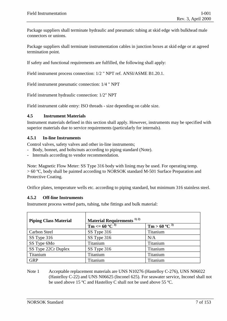
4.5.2 Off-line InstrumentsInstrument process wetted parts, tubing, tube fittings and bulk material:
Piping Class Material Material Requirements 1) 2)
Tm <= 60 ºC 3) Tm > 60 ºC 3)
Carbon Steel SS Type 316 TitaniumSS Type 316 SS Type 316 N/ASS Type 6Mo Titanium TitaniumSS Type 22Cr Duplex SS Type 316 TitaniumTitanium Titanium TitaniumGRP Titanium Titanium
Note 1 Acceptable replacement materials are UNS N10276 (Hastelloy C-276), UNS N06022(Hastelloy C-22) and UNS N06625 (Inconel 625). For seawater service, Inconel shall notbe used above 15 ºC and Hastelloy C shall not be used above 55 ºC.
Field Instrumentation I-001Rev. 3, April 2000
NORSOK Standard 8 of 153
Note 2 Titanium shall not be used for HF acid or pure Methanol service.
Note 3 Tm= Material selection temperature
a) Instrument tubing, fittings etc. without heat tracing and/or insulation:
Instrument side of isolation valve:If stagnant condition: Tm= Operating temp. of the line to which the
instrument is connected reduced with 25 ºC.Applicable for the operating temp above25 ºC.
If circulation: Tm= Operating temp. of the line to which theinstrument is connected.
Off instrument side of isolation valve: Tm= Operating temp. of the line to which theinstrument is connected.
b) Instrument tubing, fitting etc., with heat tracing and/or insulation:
Tm = Operating temp. of the line to which theinstrument is connected, or max. heat tracingoperation range, whichever is the highest.
4.5.3 Instrument HousingInstrument housing shall be resistant to saline atmosphere.
4.6 Air Supply DesignFor users requiring filtered ring main pressure air supply, two air filters with isolation valves shall beprovided in parallel before a distribution manifold.For users requiring filtered reduced air supply, two air filter regulators with isolation valves shall beprovided before a distribution manifold. Each branch off shall be provided with a 1/2" isolationvalve.
Minimum two spare branch off with valve and plug shall be provided for each manifold.
Air manifolds shall be provided with a drain isolation valve at lowest point.
Simplified air supply arrangements may be used for few and/or non critical consumers.
4.7 Instrument Installation Bulk MaterialsThe selected compression tube fitting make shall be used throughout the whole installation. Thecompression fittings shall have 2 seal rings (twin ferrules).
Pressure ratings for compression tubes, tube - and pipe fittings, instrument valves and manifolds shallcomply with the corresponding process requirements.
Tubing shall be seamless and shall be in metric sizes.
Compression tube fitting threads: NPT
Field Instrumentation I-001Rev. 3, April 2000
NORSOK Standard 9 of 153
Standard tubing sizes:Signal air, impulse tubing, instrument air supply to instrumentsand hydraulic supply (below 413 barg) 10 x 1.5 mm " (max. 520 Barg ): 10 x 2.0 mmInstrument air supply 25 x 1.5 mm
The Supplier shall use the standard tubing sizes and shall evaluate and advice if other outsidediameters is required for any reason.
4.8 Temperature Measurements
4.8.1 GeneralTemperature measurements shall be performed by Pt 100 elements (RTD - Resistance TemperatureDevice) in accordance with EN 60751.
For temperature measurements above 600 degrees C, thermocouple material Chromel Alumel, typeK, in accordance with EN 60584-1/2 should be used.
Temperature transmitters shall be included within the sensor head except for motor windingtemperature measurement and similar.
Temperature sensors not accessible during operation shall for the selected critical equipment beinstalled with backup.
Surface mounted temperature elements may be used if accuracy and response requirements are met.
4.8.2 ThermowellsThermowells shall be of the flanged type, size 1.5". For tanks, vessels and piping with pressure class2500 lb and above, the size shall be 2".
For non-critical utility service, thermowells of threaded type, NPT, can be accepted.
Thermowells shall not be longer than strictly necessary to obtain required accuracy and to avoidvibration "cracking".
Thermowell strength calculations shall be performed for process hydrocarbon systems according toANSI/ASME Performance Test Codes 19.3. -1974, chapter 1, section 8-19 thermowells.
Thermowell inner diameter suitable for TE/TI elements of 6 mm should be used.
4.8.3 Temperature GaugesBi-metallic temperature gauges with 100 mm nominal head diameter should be used for localindication.
Temperature gauges with capillary tubing should not be used.
Manufacturer’s standard ranges should be used.
Field Instrumentation I-001Rev. 3, April 2000
NORSOK Standard 10 of 153
4.9 Flow Measurements
4.9.1 GeneralMeasuring principles and technology shall be selected according to application. Typical evaluationcriteria are as follows:
• high accuracy requirements• high range ability requirements• low pressure-drop requirements• dirty fluids• large pipe sizes• low flows• straight pipe requirements
All flow elements shall be marked with flow direction.
4.9.2 Flow Orifice Plates, Nozzles and Venturi TubesFlow orifice plates, nozzles and venturi tubes shall be calculated, manufactured and installedaccording to ISO 5167.
Straight length requirements shall as a minimum satisfy the "0.5 additional uncertainty"requirements.
Welded neck orifice flanges to ANSI B16.36 with flange tapping is standard.
Temporarily installed spacers shall be clearly marked as such.
4.10 Pressure Measurement
4.10.1 GeneralIf pulsating pressure is likely to occur, a pulsation dampener shall be used.
All pressure instruments shall withstand a pressure of minimum 130 % of upper range value withoutneed for recalibration.
Differential pressure instruments shall be able to withstand full static (line) pressure on each of theinputs with the other at zero without need for recalibration.
Differential pressure instruments for low ranges equipped with capillaries and chemical seals shouldbe avoided.
4.10.2 Pressure GaugesPressure gauges shall be of the heavy duty, safety type with blow-out back as defined in recognisedstandard.
Gauges with ranges from 0.6 barg, shall have bourdon type element and shall have liquid filledhouse/case.
Field Instrumentation I-001Rev. 3, April 2000
NORSOK Standard 11 of 153
The nominal house/case diameter should be 100 mm for pressure gauges and 160 mm for differentialpressure gauges, both with bottom connection.
The manufacturer’s standard ranges should be used.
4.11 Level Measurement
4.11.1 GeneralDirect vessel mounted instruments with non-moving parts should be used.Measuring principles shall be selected according to application. Typical evaluation criteria are asfollows:
• non moving parts• density• pressure• accuracy• temperature• vessel geometry• nozzle locations• clogging
4.11.2 Local Level Indicators (Gauges)Level indicators shall cover maximum and minimum operational levels including high/low trippoints.
Gauges with magnetic indicators should be used for hydrocarbon service, except for interface(oil/water) application.
If reflex and transparent type gauges are used, they shall have forged steel column and toughenedglass.
Level gauge glasses shall have flanged connections and shall be fitted with gauge valves with offsetpattern and safety ball check valves.
If several level glasses are used, visible sections shall overlap by not less than 50 mm.
The installation shall be fitted with process isolation, drain and vent valves complying withNORSOK standard L-CR-003 Piping Details.
Simpler solutions may be used on small and non critical vessels.
Field Instrumentation I-001Rev. 3, April 2000
NORSOK Standard 12 of 153
4.12 Control Valves
4.12.1 Valve RequirementsSizing of control valves shall be made in accordance with the IEC 534-2 / ISA 75.01 standards and/orthe control valve Supplier's sizing computer program.
Globe valves should be used but depending on service conditions and application other types may beused.
The size of valves should be 1, 1.5, 2, 3, 4, 6, 8, 10 inch and higher.
All valves shall be equipped with integrated position indicators.
When requirements to max. allowable leakage rate has to be set, ANSI/FCI 70-2 shall be applied.
Face to face dimensions shall be according to ANSI B16.10.
Arrow indicating direction of the flow shall be permanently marked on each side of the valve body.
Self-acting control valves shall be used only when a sufficient differential pressure exists.
4.12.2 Actuator Requirements for Control ValvesSpring return pneumatic diaphragm/piston type actuators should be used.
Where service condition or valve design exclude the use of above mentioned principal, double actingpneumatic piston actuators should be applied. Hydraulic or electric actuators may be used for specialapplications.
By loss of signal/supply the valve shall take the position required.
Electro-pneumatic positioners should be used for remote control.
4.13 Solenoid ValvesSolenoid valves shall not be used for direct operation in pipes with process media.
Solenoid valves should be used in signal/impulse lines for air and hydraulic.
4.14 Pressure Relief Valves/Bursting DiscsAll the pressure relief valves shall be sized in accordance with the information on the data sheet andthe method outlined in API RP 520, part I and II, for sizing of pressure relief valves for hydrocarbonsystems.
Flanged steel safety relief valves for hydrocarbon systems shall conform to API 526.
Relief valves for the process piping, excluding steam and air pressure piping shall be of the enclosedspring type.
Field Instrumentation I-001Rev. 3, April 2000
NORSOK Standard 13 of 153
All relief valves for hydrocarbon systems shall conform to ASME VIII.
Seat tightness of pressure relief valves shall conform to API 527.
The total effective flow area of the orifice(s) selected shall exceed the calculated area only by anamount as limited by standard orifice sizes available.
Before orifice sizes Q, R and T are implemented, the relief valve manufacturer shall criticallyevaluate these large sizes against process medium/conditions.
The number of relief valves shall be kept to a minimum in a multiple safety valve installation.
In a multiple safety valve installation, all orifices shall be equal.
Design, sizing and approval of relief valves for utility systems shall be done to a recognisedinternational standard/institution.
Bursting discs shall be designed according to BS 2915 or equivalent.
4.15 On/Off Valve Actuators
4.15.1 GeneralAt minimum supply pressure the actuator's torque/thrust shall be 25 % above maximum torque/thrustrequired at max. differential pressure across the valve.
The actuator shall be provided with a local indicator showing the valve position.
By loss of signal/supply the valve shall take the position required.
Devices for control of the speed in both directions shall be installed on the control unit. It shall not bepossible to fully close the restrictors.
Electrical actuators may be used for non safety applications.
4.15.2 Shutdown/Blowdown ApplicationHydraulic or pneumatic single-acting spring return operated actuators should be used for shut-downvalves. Double-acting actuators may be used when this proves beneficial based on an evaluationincluding weight, space and price. Hydraulic actuators should be used.
Hydraulic accumulators shall be of the piston type, nitrogen charged, with piston position detectionpossibility.
The valve control accumulator units shall be installed close to the valve.
Field Instrumentation I-001Rev. 3, April 2000
NORSOK Standard 14 of 153
4.16 Choke ValvesRemote operated production choke valves should be provided with stepping actuator.
Each step for both directions shall be equal in length.
Manual operation in both directions shall be possible.
4.17 HVAC ActuatorsActuators for HVAC shut-off and fire dampers shall be of spring return type.Pneumatic HVAC actuators shall be designed to operate properly between max. 12.5 barg and min5.6 barg air supply pressure.
The spring force shall be selected to keep the blade(s) in proper alignment, ensure air tightness inclosed position and prevent chattering.
Actuators for HVAC pressure control dampers shall be provided with positioners.
4.18 Vibration Field InstrumentsVibration/proximity probes for vibration detection shall conform to API RP 670 and API RP 678 asrelevant.
4.19 Fire & Gas Detectors
4.19.1 GeneralSensors shall be unaffected by ambient conditions.
Fire and Gas detectors may be of the smart/addressable (e.g. field bus) type.
Detectors should have a self test system. This system should be automatically operated.
4.19.2 Smoke DetectorsDetectors shall not be sensitive to water vapour.
The application shall determine the detection principle to be used.
Detectors shall have local alarm indicators to visually indicate when detectors are in alarm mode.
Very early smoke detection system may be used for cabinets in LER's.
4.19.3 Heat DetectorHeat detectors shall not be installed unless no other detection principle can be utilised.
Heat detectors and settings shall be selected in accordance with NFPA 72E 3-3 Temperatureclassification.
Field Instrumentation I-001Rev. 3, April 2000
NORSOK Standard 15 of 153
4.19.4 Flame DetectorDetector shall be of the IR or combination IR/UV type.
The application shall determine the type to be used.
Sensors shall not be susceptible to spectral response variation when subjected to continuousoperation.
4.19.5 Gas DetectorLine detectors (open path) shall be evaluated in combination with point detection.
IR detectors should be used.
Application shall determine if catalytic detectors should be used.
Field Instrumentation I-001Rev. 3, April 2000
NORSOK Standard 16 of 153
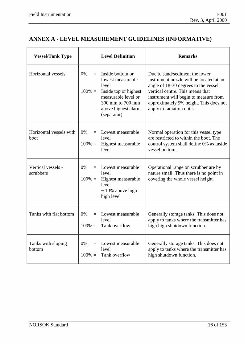
ANNEX A - LEVEL MEASUREMENT GUIDELINES (INFORMATIVE)
Vessel/Tank Type Level Definition Remarks
Horizontal vessels 0% =
100% =
Inside bottom orlowest measurablelevelInside top or highestmeasurable level or300 mm to 700 mmabove highest alarm(separator)
Due to sand/sediment the lowerinstrument nozzle will be located at anangle of 18-30 degrees to the vesselvertical centre. This means thatinstrument will begin to measure fromapproximately 5% height. This does notapply to radiation units.
Horizontal vessels withboot
0% =
100% =
Lowest measurablelevelHighest measurablelevel
Normal operation for this vessel typeare restricted to within the boot. Thecontrol system shall define 0% as insidevessel bottom.
Vertical vessels -scrubbers
0% =
100% =
Lowest measurablelevelHighest measurablelevel~ 10% above highhigh level
Operational range on scrubber are bynature small. Thus there is no point incovering the whole vessel height.
Tanks with flat bottom 0% =
100%=
Lowest measurablelevelTank overflow
Generally storage tanks. This does notapply to tanks where the transmitter hashigh high shutdown function.
Tanks with slopingbottom
0% =
100% =
Lowest measurablelevelTank overflow
Generally storage tanks. This does notapply to tanks where the transmitter hashigh shutdown function.
Field Instrumentation I-001Rev. 3, April 2000
NORSOK Standard 17 of 153
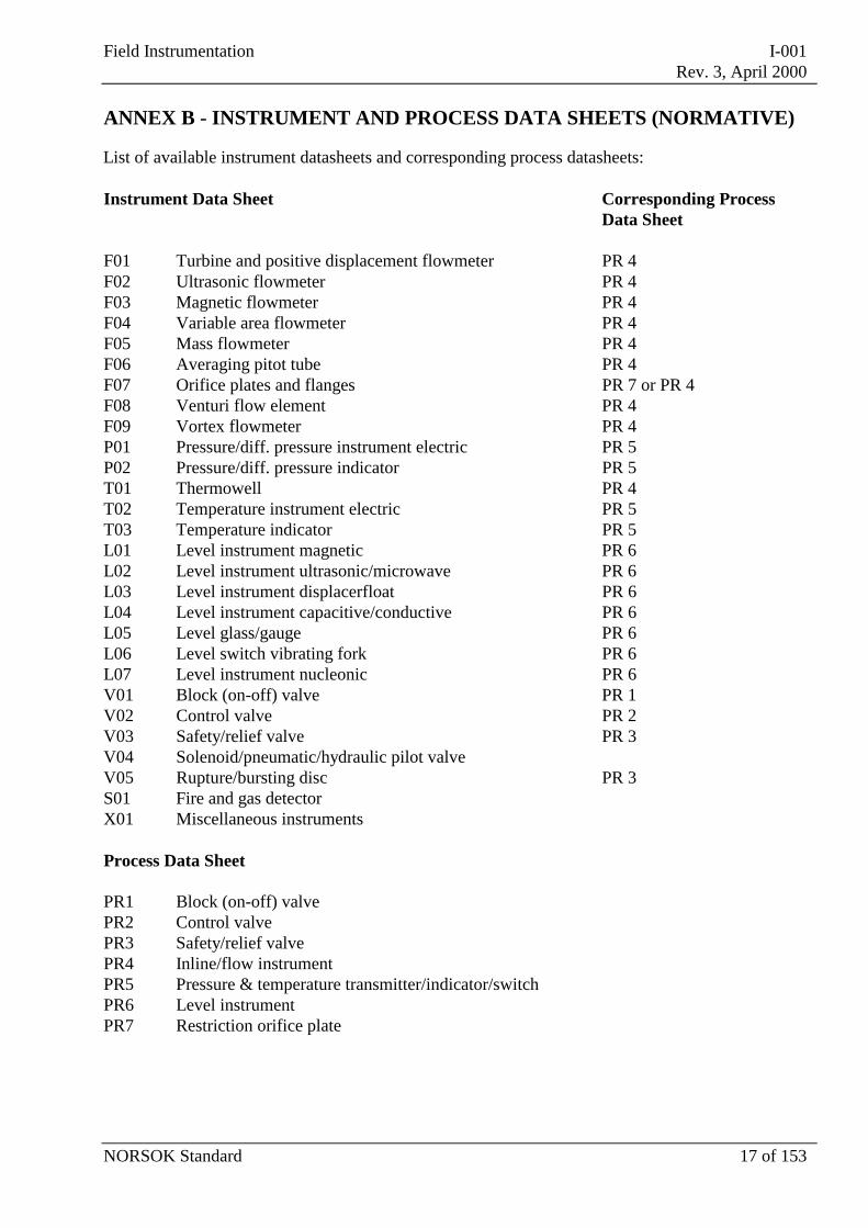
ANNEX B - INSTRUMENT AND PROCESS DATA SHEETS (NORMATIVE)
List of available instrument datasheets and corresponding process datasheets:
Instrument Data Sheet Corresponding ProcessData Sheet
F01 Turbine and positive displacement flowmeter PR 4F02 Ultrasonic flowmeter PR 4F03 Magnetic flowmeter PR 4F04 Variable area flowmeter PR 4F05 Mass flowmeter PR 4F06 Averaging pitot tube PR 4F07 Orifice plates and flanges PR 7 or PR 4F08 Venturi flow element PR 4F09 Vortex flowmeter PR 4P01 Pressure/diff. pressure instrument electric PR 5P02 Pressure/diff. pressure indicator PR 5T01 Thermowell PR 4T02 Temperature instrument electric PR 5T03 Temperature indicator PR 5L01 Level instrument magnetic PR 6L02 Level instrument ultrasonic/microwave PR 6L03 Level instrument displacerfloat PR 6L04 Level instrument capacitive/conductive PR 6L05 Level glass/gauge PR 6L06 Level switch vibrating fork PR 6L07 Level instrument nucleonic PR 6V01 Block (on-off) valve PR 1V02 Control valve PR 2V03 Safety/relief valve PR 3V04 Solenoid/pneumatic/hydraulic pilot valveV05 Rupture/bursting disc PR 3S01 Fire and gas detectorX01 Miscellaneous instruments
Process Data Sheet
PR1 Block (on-off) valvePR2 Control valvePR3 Safety/relief valvePR4 Inline/flow instrumentPR5 Pressure & temperature transmitter/indicator/switchPR6 Level instrumentPR7 Restriction orifice plate
Field Instrumentation I-001Rev. 3, April 2000
NORSOK Standard 18 of 153
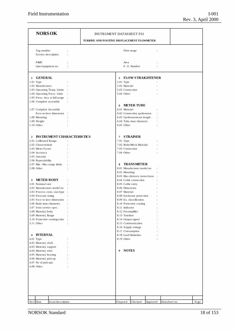
NORSOK INSTRUMENT DATASHEET F01
TURBINE AND POS ITIVE DISPLACEMENT FLOWMETER
Tag number : Flow range :Service description :
P&ID : Area :Line /equipment no. : P . O. Number :
1 GENERAL 5 FLOW STRAIGHTENER1.01 Type : 5.01 Type :1.02 Manufacture r : 5.02 Materia l :1.03 Opera ting Temp. Limits : 5.03 Connection :1.04 Opera ting Pres s . Limit : 5.04 Other :1.05 Press . los s a t full range :1.06 Comple te as sembly :
6 METER TUBE1.07 Comple te Assembly 6.01 Materia l :
Face-to-face dimens ion : 6.02 Connection up/downs tr. :1.08 Mounting : 6.03 Up/downs tream length :1.09 Weight : 6.04 Tube inne r diameter :1.10 Other : 6.05 Other :
2 INSTRUMENT CHARACTERISTICS 7 STRAINER2.01 Ca librated Range : 7.01 Type :2.02 Characte ris tic : 7.02 Body/Mes h Mate ria l :2.03 Meter Factor : 7.03 Connection :2.04 Accuracy : 7.04 Other :2.05 Linearity :2.06 Repea tability :2.07 Min / Max range limits : 8 TRANSMITTER2.08 Other : 8.01 Manufacture r mode l no :
8.02 Mounting :8.03 Max dis tance mete r/trans :
3 METER BODY : 8.04 Cable connection :3.01 Nomina l s ize : 8.05 Cable entry :3.02 Manufacture r mode l no : 8.06 Dimens ion :3.03 Process conn. s ize /type : 8.07 Materia l :3.04 Pressure ra ting : 8.08 Enclosure protection :3.05 Face to face dimens ion : 8.09 Ex. clas s ification :3.06 Body inne r diamete r : 8.10 Protective coa ting :3.07 Sour service spec. : 8.11 Indica tor :3.08 Materia l, body : 8.12 Preamplifier :3.09 Materia l, flange : 8.13 Tota lize r :3.10 Protective coa ting/color : 8.14 Output s igna l :3.11 Other : 8.15 Communica tion :
8.16 Supply voltage :8.17 Consumption :
4 INTERNAL 8.18 Load limita tion :4.01 Type : 8.19 Other :4.02 Materia l, shaft :4.03 Materia l, support :4.04 Materia l, rotor : 9 NOTES4.05 Materia l, bea ring :4.06 Materia l, pick-up :4.07 No of pick-ups :4.08 Other :
Rev Date Is sue /description Prepared Checked Approved Datas heet no. Page
Field Instrumentation I-001Rev. 3, April 2000
NORSOK Standard 19 of 153
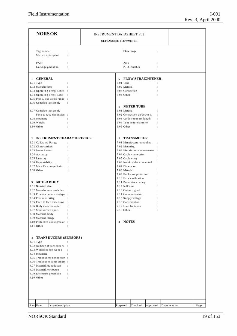
NORSOK INSTRUMENT DATASHEET F02
ULTRAS ONIC FLOWMETER
Tag number : Flow range :Service description :
P&ID : Area :Line /equipment no. : P . O. Number :
1 GENERAL 5 FLOW STRAIGHTENER1.01 Type : 5.01 Type :1.02 Manufacture r : 5.02 Materia l :1.03 Operating Temp. Limits : 5.03 Connection :1.04 Operating Pres s . Limit : 5.04 Other :1.05 Press . los s a t full range :1.06 Comple te as s embly :
6 METER TUBE1.07 Comple te as s embly 6.01 Materia l :
Face-to-face dimens ion : 6.02 Connection up/downs tr. :1.08 Mounting : 6.03 Up/downs tream length :1.09 Weight : 6.04 Tube inne r diameter :1.10 Other : 6.05 Other :
2 INSTRUMENT CHARACTERISTICS 7 TRANSMITTER2.01 Ca librated Range : 7.01 Manufacture r mode l no :2.02 Characte ris tic : 7.02 Mounting :2.03 Meter Factor : 7.03 Max dis tance meter/trans :2.04 Accuracy : 7.04 Cable connection :2.05 Linearity : 7.05 Cable entry :2.06 Repea tability : 7.06 No of cables connected :2.07 Min / Max range limits : 7.07 Dimens ion :2.08 Other : 7.08 Materia l :
7.09 Enclosure protection :7.10 Ex. cla s s ification :
3 METER BODY 7.11 Protective coating :3.01 Nomina l s ize : 7.12 Indica tor :3.02 Manufacture r mode l no : 7.13 Output s igna l :3.03 Process conn. s ize /type : 7.14 Communication :3.04 Pressure ra ting : 7.15 Supply voltage :3.05 Face to face dimens ion : 7.16 Consumption :3.06 Body inne r diameter : 7.17 Load limita tion :3.07 Sour service spec. : 7.18 Other :3.08 Materia l, body :3.09 Materia l, flange :3.10 Protective coating/color : 8 NOTES3.11 Other :
4 TRANSDUCERS (SENSORS)4.01 Type :4.02 Number of transducers :4.03 Wetted or non-we tted :4.04 Mounting :4.05 Transducers connection :4.06 Transducer cable length :4.07 Materia l, transducers :4.08 Materia l, enclosure :4.09 Enclosure protection :4.10 Other :
Rev Date Is sue /description Prepared Checked Approved Datashee t no. Page
Field Instrumentation I-001Rev. 3, April 2000
NORSOK Standard 20 of 153
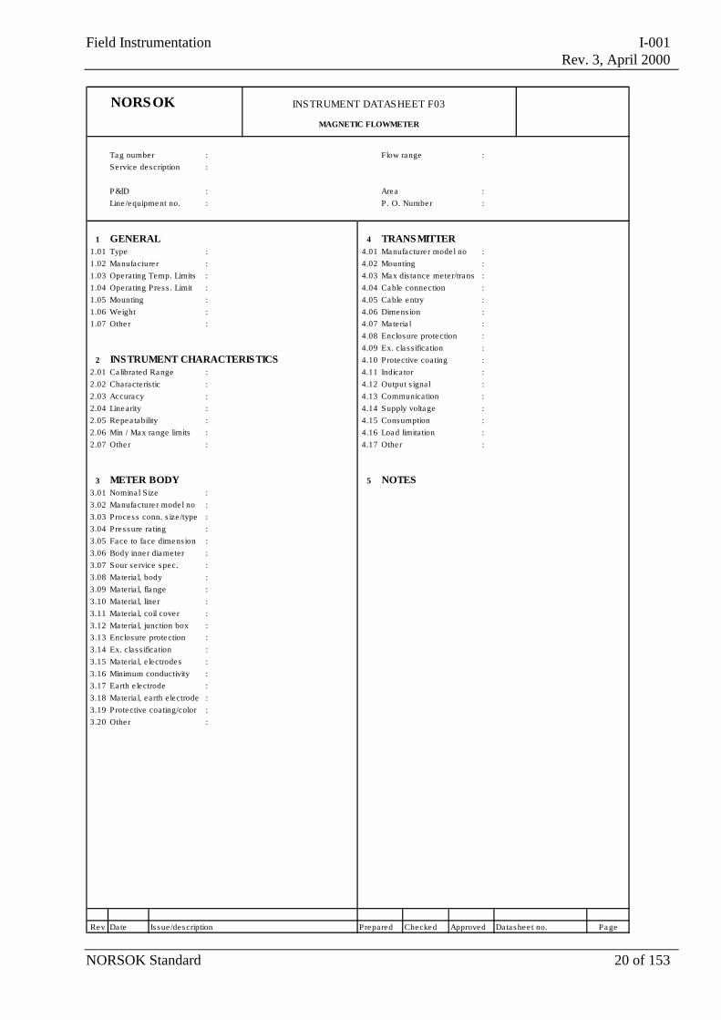
NORSOK INSTRUMENT DATASHEET F03
MAGNETIC FLOWMETER
Tag number : Flow range :Service description :
P&ID : Area :Line /equipment no. : P . O. Number :
1 GENERAL 4 TRANSMITTER1.01 Type : 4.01 Manufacture r mode l no :1.02 Manufacture r : 4.02 Mounting :1.03 Operating Temp. Limits : 4.03 Max dis tance meter/trans :1.04 Operating Pres s . Limit : 4.04 Cable connection :1.05 Mounting : 4.05 Cable entry :1.06 Weight : 4.06 Dimens ion :1.07 Other : 4.07 Materia l :
4.08 Enclosure protection :4.09 Ex. cla s s ification :
2 INSTRUMENT CHARACTERISTICS 4.10 Protective coating :2.01 Ca librated Range : 4.11 Indica tor :2.02 Characte ris tic : 4.12 Output s igna l :2.03 Accuracy : 4.13 Communication :2.04 Linearity : 4.14 Supply voltage :2.05 Repea tability : 4.15 Consumption :2.06 Min / Max range limits : 4.16 Load limita tion :2.07 Other : 4.17 Other :
3 METER BODY 5 NOTES3.01 Nomina l S ize :3.02 Manufacture r mode l no :3.03 Process conn. s ize /type :3.04 Pressure ra ting :3.05 Face to face dimens ion :3.06 Body inne r diameter :3.07 Sour service spec. :3.08 Materia l, body :3.09 Materia l, flange :3.10 Materia l, line r :3.11 Materia l, coil cover :3.12 Materia l, junction box :3.13 Enclosure protection :3.14 Ex. cla s s ification :3.15 Materia l, e lectrodes :3.16 Minimum conductivity :3.17 Earth e lectrode :3.18 Materia l, earth e lectrode :3.19 Protective coating/color :3.20 Other :
Rev Date Is sue /description Prepared Checked Approved Datashee t no. Page
Field Instrumentation I-001Rev. 3, April 2000
NORSOK Standard 21 of 153
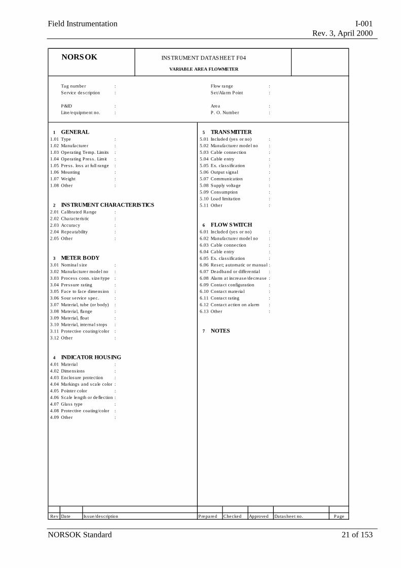
NORSOK INSTRUMENT DATASHEET F04
VARIABLE AREA FLOWMETER
Tag number : Flow range :Service description : Se t/Ala rm P oint :
P&ID : Area :Line/equipment no. : P . O. Number :
1 GENERAL 5 TRANSMITTER1.01 Type : 5.01 Included (yes or no) :1.02 Manufacture r : 5.02 Manufacture r mode l no :1.03 Opera ting Temp. Limits : 5.03 Cable connection :1.04 Opera ting Pres s . Limit : 5.04 Cable entry :1.05 Press . los s a t full range : 5.05 Ex. cla s s ification :1.06 Mounting : 5.06 Output s igna l :1.07 Weight : 5.07 Communication :1.08 Other : 5.08 Supply voltage :
5.09 Consumption : 5.10 Load limita tion :
2 INSTRUMENT CHARACTERISTICS 5.11 Other :2.01 Calibra ted Range :2.02 Characte ris tic :2.03 Accuracy : 6 FLOW SWITCH2.04 Repea tability : 6.01 Included (yes or no) :2.05 Other : 6.02 Manufacture r mode l no :
6.03 Cable connection :6.04 Cable entry :
3 METER BODY 6.05 Ex. cla s s ification :3.01 Nomina l s ize : 6.06 Rese t; automatic or manua l :3.02 Manufacture r mode l no : 6.07 Deadband or differentia l :3.03 Process conn. s ize/type : 6.08 Ala rm a t increase /decrease :3.04 Pressure ra ting : 6.09 Contact configuration :3.05 Face to face dimens ion : 6.10 Contact mate ria l :3.06 Sour se rvice spec. : 6.11 Contact ra ting :3.07 Mate ria l, tube (or body) : 6.12 Contact action on ala rm :3.08 Mate ria l, flange : 6.13 Other :3.09 Mate ria l, float :3.10 Mate ria l, interna l s tops :3.11 Protective coa ting/color : 7 NOTES3.12 Other :
4 INDICATOR HOUSING
4.01 Mate ria l :4.02 Dimens ions :4.03 Enclosure protection :4.04 Markings and sca le color :4.05 Pointe r color :4.06 Sca le length or de flection :4.07 Glass type :4.08 Protective coa ting/color :4.09 Other :
Rev Date Is sue/description Prepared Checked Approved Datashee t no. Page

Field Instrumentation I-001Rev. 3, April 2000
NORSOK Standard 22 of 153
NORSOK INSTRUMENT DATASHEET F05
MASS FLOWMETER
Tag number : Flow range :Service description :
P&ID : Area :Line /equipment no. : P . O. Number :
1 GENERAL 4 TRANSMITTER1.01 Type : 4.01 Manufacture r mode l no :1.02 Manufacture r : 4.02 Mounting :1.03 Operating Temp. Limits : 4.03 Max dis tance mete r/trans :1.04 Operating Pres s . Limit : 4.04 Cable connection :1.05 Press . los s a t full range : 4.05 Cable entry :1.06 Mounting : 4.06 Dimens ion :1.07 Weight : 4.07 Materia l :1.08 Other : 4.08 Enclosure protection :
4.09 Ex. cla s s ification : 4.10 Protective coating :
2 INSTRUMENT CHARACTERISTICS 4.11 Indica tor :2.01 Ca librated Range : 4.12 Output s igna l :2.02 Characte ris tic : 4.13 Communication :2.03 Accuracy : 4.14 Supply voltage :2.04 Linearity : 4.15 Consumption :2.05 Repea tability : 4.16 Load limita tion :2.06 Min / Max range limits : 4.17 Other :2.07 Other :
5 NOTES3 METER BODY
3.01 Nomina l s ize :3.02 Manufacture r mode l no :3.03 Process conn. s ize /type :3.04 Pressure ra ting :3.05 Face to face dimens ion :3.06 Number of tube runs :3.07 Tube inne r diameter :3.08 Materia l, tube :3.09 Materia l, flange/connect. :3.10 Sour service spec. :3.11 Materia l, tube cover :3.12 Enclosure protection :3.13 Protective coating/color :3.14 Other :
Rev Date Is sue /description Prepared Checked Approved Datasheet no. Page
Field Instrumentation I-001Rev. 3, April 2000
NORSOK Standard 23 of 153
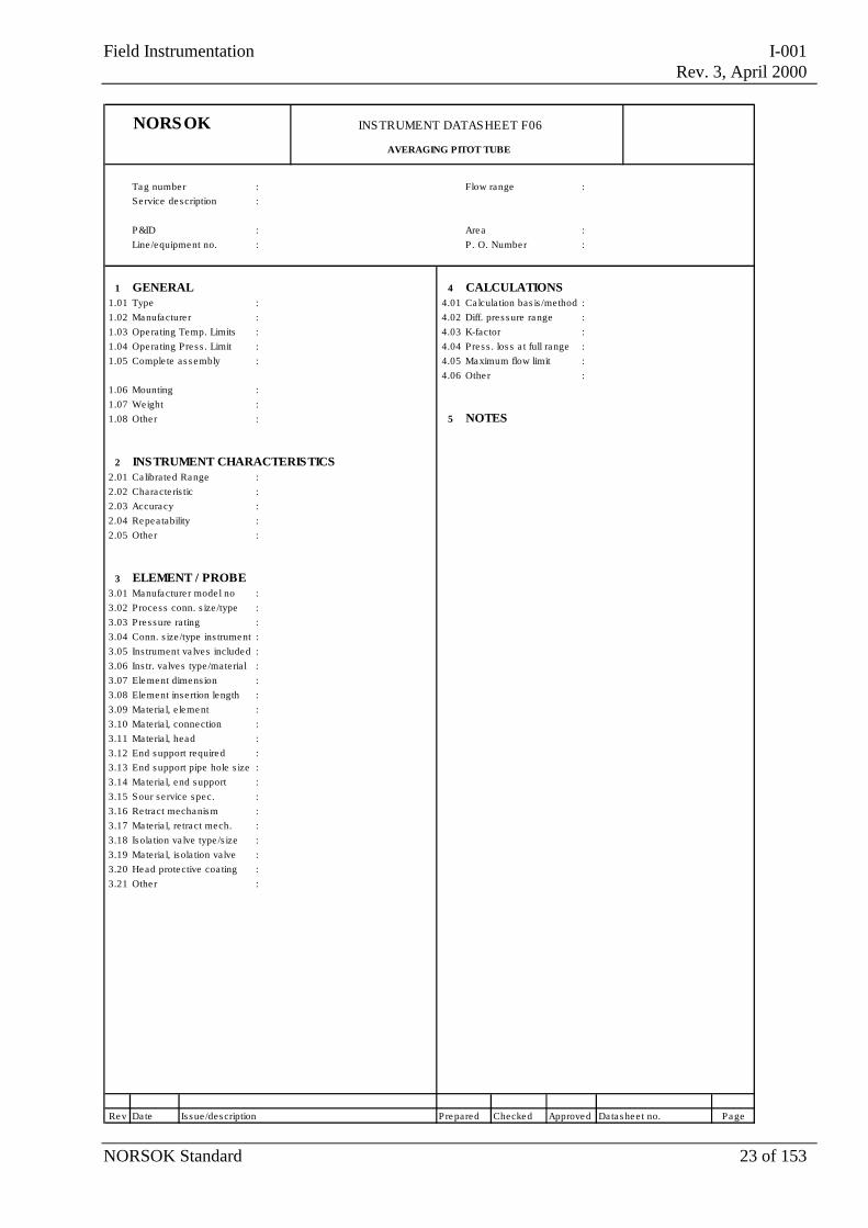
NORSOK INSTRUMENT DATASHEET F06
AVERAGING PITOT TUBE
Tag number : Flow range :Service description :
P&ID : Area :Line /equipment no. : P . O. Number :
1 GENERAL 4 CALCULATIONS1.01 Type : 4.01 Ca lcula tion bas is /method :1.02 Manufacture r : 4.02 Diff. pres sure range :1.03 Operating Temp. Limits : 4.03 K-factor :1.04 Operating Press . Limit : 4.04 Press . los s a t full range :1.05 Comple te as s embly : 4.05 Maximum flow limit :
4.06 Other :1.06 Mounting :1.07 Weight :1.08 Other : 5 NOTES
2 INSTRUMENT CHARACTERISTICS2.01 Ca librated Range :2.02 Characte ris tic :2.03 Accuracy :2.04 Repea tability :2.05 Other :
3 ELEMENT / PROBE3.01 Manufacture r mode l no : 3.02 Process conn. s ize /type :3.03 Pressure ra ting :3.04 Conn. s ize /type ins trument :3.05 Ins trument va lves included :3.06 Ins tr. valves type /materia l :3.07 Element dimens ion :3.08 Element inse rtion length :3.09 Materia l, e lement :3.10 Materia l, connection :3.11 Materia l, head :3.12 End support required :3.13 End support pipe hole s ize :3.14 Materia l, end support :3.15 Sour service spec. :3.16 Re tract mechanism :3.17 Materia l, re tract mech. :3.18 Isolation va lve type /s ize :3.19 Materia l, isola tion valve :3.20 Head protective coa ting :3.21 Other :
Rev Date Is sue /description Prepared Checked Approved Datashee t no. Page
Field Instrumentation I-001Rev. 3, April 2000
NORSOK Standard 24 of 153
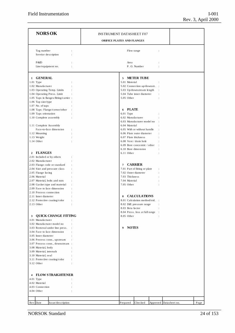
NORSOK INSTRUMENT DATASHEET F07
ORIFICE PLATES AND FLANGES
Tag number : Flow range :Service description :
P&ID : Area :Line /equipment no. : P . O. Number :
1 GENERAL 5 METER TUBE
1.01 Type : 5.01 Materia l :1.02 Manufacture r : 5.02 Connection up/downs tr. :1.03 Operating Temp. Limits : 5.03 Up/downs tream length :1.04 Operating Pres s . Limit : 5.04 Tube inne r diameter :1.05 Taps in flanges /fitting/ca rrie r : 5.05 Other :1.06 Tap s ize /type :1.07 No. of taps :1.08 Taps : Flange/corner/other : 6 PLATE 1.09 Taps orienta tion : 6.01 Type :1.10 Comple te as sembly : 6.02 Manufacture r :
6.03 Manufacture r mode l no :1.11 Comple te Assembly 6.04 Materia l :
Face-to-face dimens ion : 6.05 With or without handle :1.12 Mounting : 6.06 Pla te outer diamete r :1.13 Weight : 6.07 Pla te thickness :1.14 Other : 6.08 Vent / dra in hole :
6.09 Bore concentric / other :6.10 Bore dimens ion :
2 FLANGES 6.11 Other :2.01 Included or by others :2.02 Manufacture r :2.03 Flange code or s tandard : 7 CARRIER 2.04 Size and pres s ure clas s : 7.01 Part of fitting or pla te :2.05 Flange facing : 7.02 Oute r diameter :2.06 Materia l : 7.03 Thickness :2.07 Materia l, bolts and nuts : 7.04 Materia l :2.08 Gaske t type and mate ria l : 7.05 Other :2.09 Face to face dimens ion :2.10 Process connection :2.11 Inner diamete r : 8 CALCULATIONS2.12 Protective coa ting/color : 8.01 Ca lcula tion me thod/s td. :2.13 Other : 8.02 Diff. pres sure range :
8.03 Be ta factor :8.04 Press . los s a t full range :
3 QUICK CHANGE FITTING 8.05 Other :3.01 Manufacture r :3.02 Manufacture r mode l no :3.03 Remova l under line pres s . : 9 NOTES3.04 Face to face dimens ion :3.05 Inner diamete r :3.06 Process conn., ups tream :3.07 Process conn., downs tream :3.08 Materia l, body :3.09 Materia l, internals :3.10 Materia l, s eal :3.11 Protective coa ting/color :3.12 Other :
4 FLOW STRAIGHTENER4.01 Type :4.02 Materia l :4.03 Connection :4.04 Other :
Rev Date Is sue /description Prepared Checked Approved Datasheet no. Page
Field Instrumentation I-001Rev. 3, April 2000
NORSOK Standard 25 of 153
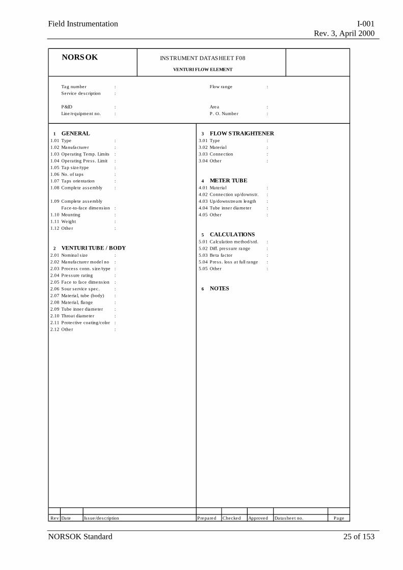
NORSOK INSTRUMENT DATASHEET F08
VENTURI FLOW ELEMENT
Tag number : Flow range :Service description :
P&ID : Area :Line /equipment no. : P . O. Number :
1 GENERAL 3 FLOW STRAIGHTENER1.01 Type : 3.01 Type :1.02 Manufacture r : 3.02 Materia l :1.03 Operating Temp. Limits : 3.03 Connection :1.04 Operating Pres s . Limit : 3.04 Other :1.05 Tap s ize/type :1.06 No. of taps :1.07 Taps orienta tion : 4 METER TUBE1.08 Comple te as s embly : 4.01 Materia l :
4.02 Connection up/downs tr. :1.09 Comple te as s embly 4.03 Up/downs tream length :
Face-to-face dimens ion : 4.04 Tube inne r diameter :1.10 Mounting : 4.05 Other :1.11 Weight :1.12 Other :
5 CALCULATIONS5.01 Ca lcula tion me thod/s td. :
2 VENTURI TUBE / BODY 5.02 Diff. pres sure range :2.01 Nomina l s ize : 5.03 Be ta factor :2.02 Manufacture r mode l no : 5.04 Press . los s a t full range :2.03 Process conn. s ize /type : 5.05 Other :2.04 Pressure ra ting :2.05 Face to face dimens ion :2.06 Sour service spec. : 6 NOTES2.07 Materia l, tube (body) :2.08 Materia l, flange :2.09 Tube inne r diameter :2.10 Throa t diamete r :2.11 Protective coating/color :2.12 Other :
Rev Date Is sue /description Prepared Checked Approved Datashee t no. Page
Field Instrumentation I-001Rev. 3, April 2000
NORSOK Standard 26 of 153
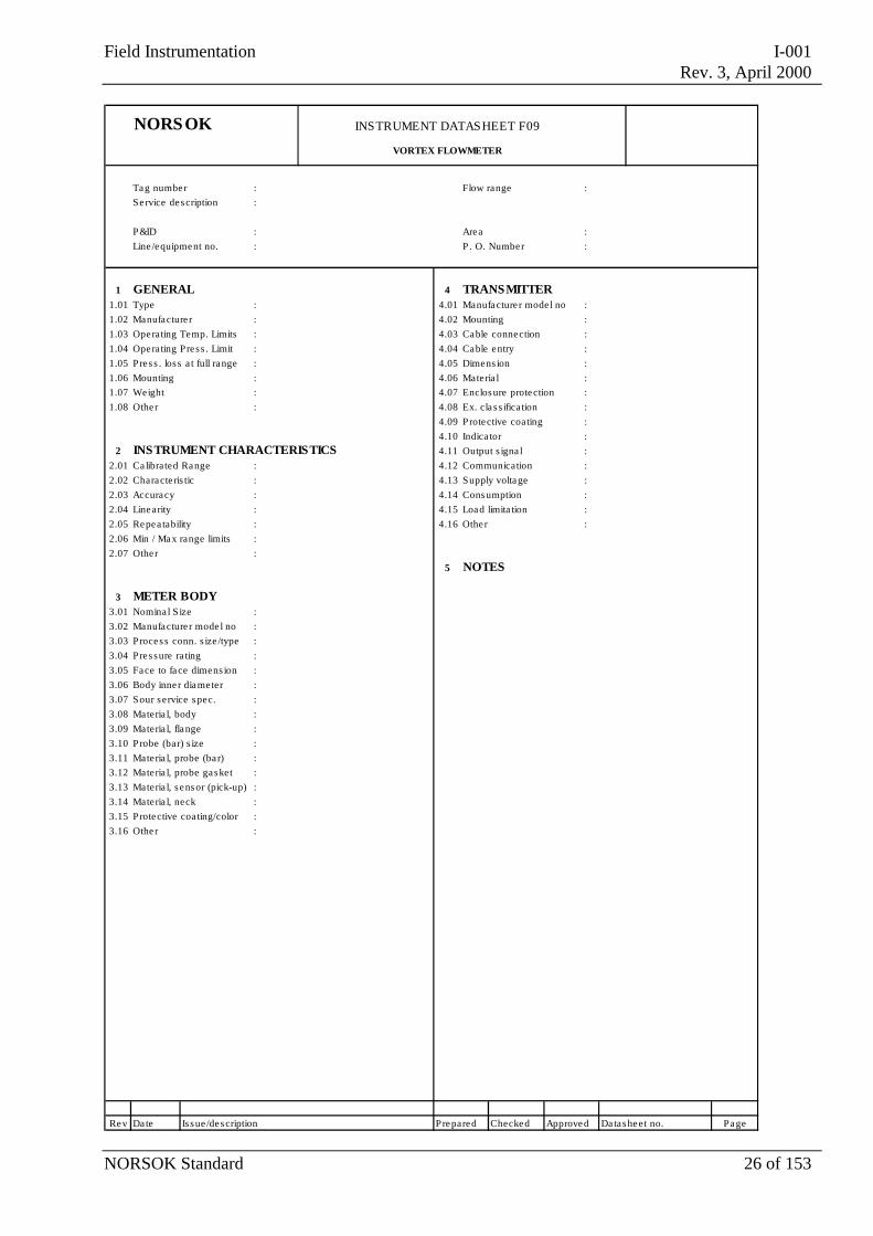
NORSOK INSTRUMENT DATASHEET F09
VORTEX FLOWMETER
Tag number : Flow range :Service description :
P&ID : Area :Line /equipment no. : P . O. Number :
1 GENERAL 4 TRANSMITTER1.01 Type : 4.01 Manufacture r mode l no :1.02 Manufacture r : 4.02 Mounting :1.03 Operating Temp. Limits : 4.03 Cable connection :1.04 Operating Pres s . Limit : 4.04 Cable entry :1.05 Press . los s a t full range : 4.05 Dimens ion :1.06 Mounting : 4.06 Materia l :1.07 Weight : 4.07 Enclosure protection :1.08 Other : 4.08 Ex. cla s s ification :
4.09 Protective coating :4.10 Indica tor :
2 INSTRUMENT CHARACTERISTICS 4.11 Output s igna l :2.01 Ca librated Range : 4.12 Communication :2.02 Characte ris tic : 4.13 Supply voltage :2.03 Accuracy : 4.14 Consumption :2.04 Linearity : 4.15 Load limita tion :2.05 Repea tability : 4.16 Other :2.06 Min / Max range limits :2.07 Other :
5 NOTES
3 METER BODY3.01 Nomina l S ize :3.02 Manufacture r mode l no :3.03 Process conn. s ize /type :3.04 Pressure ra ting :3.05 Face to face dimens ion :3.06 Body inne r diameter :3.07 Sour service spec. :3.08 Materia l, body :3.09 Materia l, flange :3.10 Probe (bar) s ize :3.11 Materia l, probe (ba r) :3.12 Materia l, probe gasket :3.13 Materia l, s ensor (pick-up) :3.14 Materia l, neck :3.15 Protective coating/color :3.16 Other :
Rev Date Is sue /description Prepared Checked Approved Datasheet no. Page
Field Instrumentation I-001Rev. 3, April 2000
NORSOK Standard 27 of 153
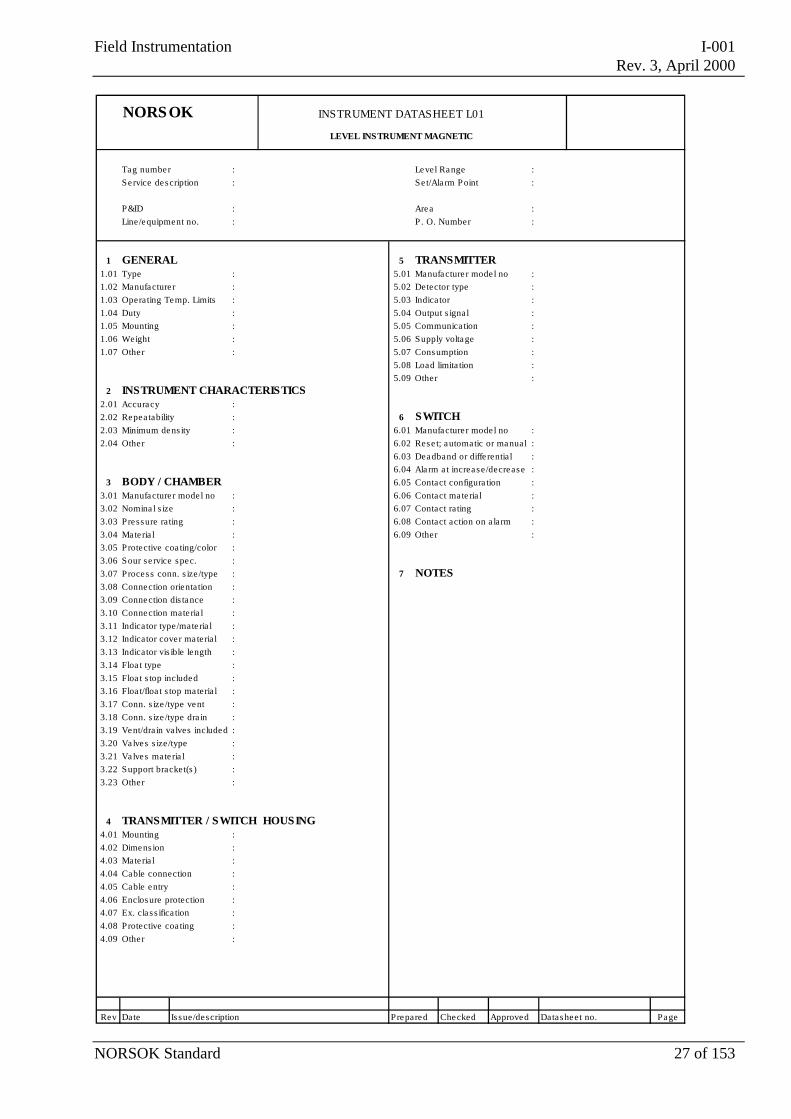
NORSOK INSTRUMENT DATASHEET L01
LEVEL INSTRUMENT MAGNETIC
Tag number : Level Range :Service description : Se t/Ala rm P oint :
P&ID : Area :Line/equipment no. : P . O. Number :
1 GENERAL 5 TRANSMITTER1.01 Type : 5.01 Manufacture r mode l no :1.02 Manufacture r : 5.02 Detector type :1.03 Operating Temp. Limits : 5.03 Indicator :1.04 Duty : 5.04 Output s ignal :1.05 Mounting : 5.05 Communica tion :1.06 Weight : 5.06 Supply voltage :1.07 Other : 5.07 Consumption :
5.08 Load limita tion :5.09 Other :
2 INSTRUMENT CHARACTERISTICS2.01 Accuracy :2.02 Repea tability : 6 SWITCH2.03 Minimum dens ity : 6.01 Manufacture r mode l no :2.04 Other : 6.02 Rese t; automatic or manual :
6.03 Deadband or diffe rentia l :6.04 Ala rm a t increase/decrease :
3 BODY / CHAMBER 6.05 Contact configura tion :3.01 Manufacture r mode l no : 6.06 Contact ma te ria l :3.02 Nomina l s ize : 6.07 Contact ra ting :3.03 Pressure rating : 6.08 Contact action on a larm :3.04 Mate ria l : 6.09 Other :3.05 Protective coa ting/color :3.06 Sour se rvice spec. :3.07 Process conn. s ize /type : 7 NOTES3.08 Connection orientation :3.09 Connection dis tance :3.10 Connection mate ria l :3.11 Indicator type/mate ria l :3.12 Indicator cover ma teria l :3.13 Indicator vis ible length :3.14 Floa t type :3.15 Floa t s top included :3.16 Floa t/floa t s top ma teria l :3.17 Conn. s ize /type vent :3.18 Conn. s ize /type dra in :3.19 Vent/drain valves included :3.20 Valves s ize/type :3.21 Valves mate ria l :3.22 Support bracket(s ) :3.23 Other :
4 TRANSMITTER / SWITCH HOUSING4.01 Mounting :4.02 Dimens ion :4.03 Mate ria l :4.04 Cable connection :4.05 Cable entry :4.06 Enclosure protection :4.07 Ex. cla s s ifica tion :4.08 Protective coa ting :4.09 Other :
Rev Date Is sue/description Prepared Checked Approved Datasheet no. Page
Field Instrumentation I-001Rev. 3, April 2000
NORSOK Standard 28 of 153
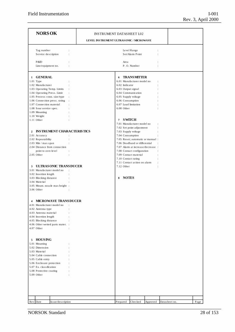
NORSOK INSTRUMENT DATASHEET L02
LEVEL INSTRUMENT ULTRASONIC / MICROWAVE
Tag number : Level Range :Service description : Se t/Ala rm P oint :
P&ID : Area :Line/equipment no. : P . O. Number :
1 GENERAL 6 TRANSMITTER1.01 Type : 6.01 Manufacture r mode l no :1.02 Manufacture r : 6.02 Indicator :1.03 Operating Temp. Limits : 6.03 Output s ignal :1.04 Operating Pres s . Limit : 6.04 Communica tion :1.05 Process conn. s ize /type : 6.05 Supply voltage :1.06 Connection press . ra ting : 6.06 Consumption :1.07 Connection mate ria l : 6.07 Load limita tion :1.08 Sour se rvice spec. : 6.08 Other :1.09 Mounting :1.10 Weight :1.11 Other : 7 SWITCH
7.01 Manufacture r mode l no :7.02 Se t point adjus tment :
2 INSTRUMENT CHARACTERISTICS 7.03 Supply voltage :2.01 Accuracy : 7.04 Consumption :2.02 Repea tability : 7.05 Rese t; automatic or manual :2.03 Min / max span : 7.06 Deadband or diffe rentia l :2.04 Dis tance from connection 7.07 Ala rm a t increase/decrease :
point to ze ro leve l : 7.08 Contact configura tion :2.05 Other : 7.09 Contact ma te ria l :
7.10 Contact ra ting :7.11 Contact action on a larm :
3 ULTRASONIC TRANSDUCER 7.12 Other :3.01 Manufacture r mode l no :3.02 Insertion length :3.03 Blocking dis tance : 8 NOTES3.04 Mate ria l :3.05 Mount. nozzle max height :3.06 Other :
4 MICROWAVE TRANSDUCER4.01 Manufacture r mode l no :4.02 Antenna type :4.03 Antenna mate ria l :4.04 Insertion length :4.05 Blocking dis tance :4.06 Other we tted parts mate r. :4.07 Other :
5 HOUSING5.01 Mounting :5.02 Dimens ion :5.03 Mate ria l :5.04 Cable connection :5.05 Cable entry :5.06 Enclosure protection :5.07 Ex. cla s s ifica tion :5.08 Protective coa ting :5.09 Other :
Rev Date Is sue/description Prepared Checked Approved Datasheet no. Page
Field Instrumentation I-001Rev. 3, April 2000
NORSOK Standard 29 of 153
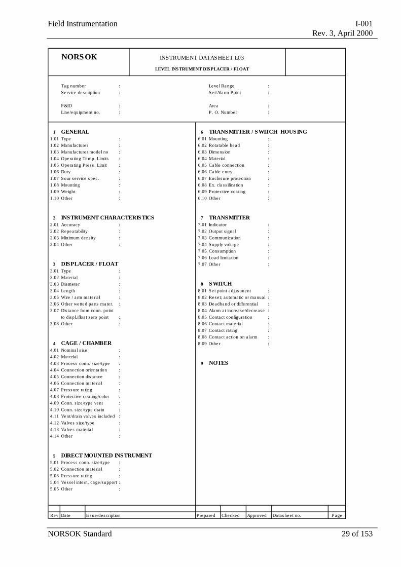
NORSOK INSTRUMENT DATASHEET L03
LEVEL INSTRUMENT DISPLACER / FLOAT
Tag number : Level Range :Service description : Se t/Ala rm P oint :
P&ID : Area :Line/equipment no. : P . O. Number :
1 GENERAL 6 TRANSMITTER / SWITCH HOUSING1.01 Type : 6.01 Mounting :1.02 Manufacture r : 6.02 Rotatable head :1.03 Manufacture r mode l no : 6.03 Dimens ion :1.04 Operating Temp. Limits : 6.04 Mate ria l :1.05 Operating Pres s . Limit : 6.05 Cable connection :1.06 Duty : 6.06 Cable entry :1.07 Sour se rvice spec. : 6.07 Enclosure protection :1.08 Mounting : 6.08 Ex. cla s s ifica tion :1.09 Weight : 6.09 Protective coa ting :1.10 Other : 6.10 Other :
2 INSTRUMENT CHARACTERISTICS 7 TRANSMITTER2.01 Accuracy : 7.01 Indicator :2.02 Repea tability : 7.02 Output s ignal :2.03 Minimum dens ity : 7.03 Communica tion :2.04 Other : 7.04 Supply voltage :
7.05 Consumption :7.06 Load limita tion :
3 DISPLACER / FLOAT 7.07 Other :3.01 Type :3.02 Mate ria l :3.03 Diamete r : 8 SWITCH3.04 Length : 8.01 Se t point adjus tment :3.05 Wire / a rm materia l : 8.02 Rese t; automatic or manual :3.06 Other we tted parts mate r. : 8.03 Deadband or diffe rentia l :3.07 Dis tance from conn. point 8.04 Ala rm a t increase/decrease :
to displ./floa t zero point : 8.05 Contact configura tion :3.08 Other : 8.06 Contact ma te ria l :
8.07 Contact ra ting :8.08 Contact action on a larm :
4 CAGE / CHAMBER 8.09 Other :4.01 Nomina l s ize :4.02 Mate ria l :4.03 Process conn. s ize /type : 9 NOTES4.04 Connection orienta tion :4.05 Connection dis tance :4.06 Connection mate ria l :4.07 Pressure ra ting :4.08 Protective coa ting/color :4.09 Conn. s ize /type vent :4.10 Conn. s ize /type dra in :4.11 Vent/drain valves included :4.12 Valves s ize/type :4.13 Valves mate ria l :4.14 Other :
5 DIRECT MOUNTED INSTRUMENT5.01 Process conn. s ize /type :5.02 Connection mate ria l :5.03 Pressure ra ting :5.04 Vessel intern. cage/support :5.05 Other :
Rev Date Is sue/description Prepared Checked Approved Datasheet no. Page
Field Instrumentation I-001Rev. 3, April 2000
NORSOK Standard 30 of 153
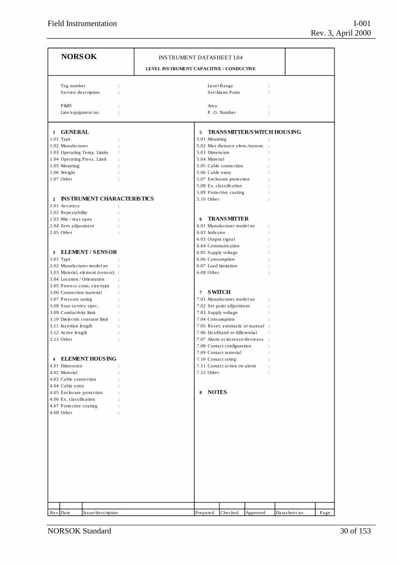
NORSOK INSTRUMENT DATASHEET L04
LEVEL INS TRUMENT CAPACITIVE / CONDUCTIVE
Tag number : Leve l Range :Service description : Se t/Ala rm P oint :
P&ID : Area :Line /equipment no. : P . O. Number :
1 GENERAL 5 TRANSMITTER/SWITCH HOUSING1.01 Type : 5.01 Mounting :1.02 Manufacture r : 5.02 Max dis tance elem./transm. :1.03 Operating Temp. Limits : 5.03 Dimens ion :1.04 Operating Pres s . Limit : 5.04 Materia l :1.05 Mounting : 5.05 Cable connection :1.06 Weight : 5.06 Cable entry :1.07 Other : 5.07 Enclosure protection :
5.08 Ex. cla s s ification :5.09 Protective coating :
2 INSTRUMENT CHARACTERISTICS 5.10 Other :2.01 Accuracy :2.02 Repea tability :2.03 Min / max span : 6 TRANSMITTER2.04 Zero adjus tment : 6.01 Manufacture r mode l no :2.05 Other : 6.02 Indica tor :
6.03 Output s igna l : 6.04 Communication :
3 ELEMENT / SENSOR 6.05 Supply voltage :3.01 Type : 6.06 Consumption :3.02 Manufacture r mode l no : 6.07 Load limita tion :3.03 Materia l, e lement (sensor) : 6.08 Other :3.04 Loca tion / Orientation :3.05 Process conn. s ize /type :3.06 Connection ma te ria l : 7 SWITCH3.07 Pressure ra ting : 7.01 Manufacture r mode l no :3.08 Sour se rvice spec. : 7.02 Se t point adjus tment :3.09 Conductivity limit : 7.03 Supply voltage :3.10 Dielectric cons tant limit : 7.04 Consumption :3.11 Inse rtion length : 7.05 Reset; automatic or manual :3.12 Active length : 7.06 Deadband or diffe rentia l :3.13 Other : 7.07 Ala rm a t increase/decrease :
7.08 Contact configura tion :7.09 Contact materia l :
4 ELEMENT HOUSING 7.10 Contact ra ting :4.01 Dimens ion : 7.11 Contact action on ala rm :4.02 Materia l : 7.12 Other :4.03 Cable connection :4.04 Cable entry :4.05 Enclosure protection : 8 NOTES4.06 Ex. cla s s ification :4.07 Protective coating :4.08 Other :
Rev Date Is sue /description Prepared Checked Approved Datashee t no. Page
Field Instrumentation I-001Rev. 3, April 2000
NORSOK Standard 31 of 153
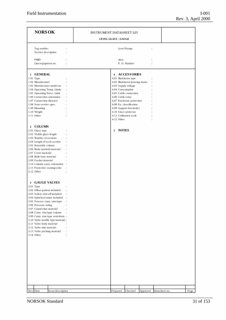
NORSOK INSTRUMENT DATASHEET L05
LEVEL GLASS / GAUGE
Tag number : Level Range :Service description :
P&ID : Area :Line/equipment no. : P . O. Number :
1 GENERAL 4 ACCESSORIES1.01 Type : 4.01 Illumina tor type :1.02 Manufacture r : 4.02 Illumina tor hous ing ma ter. :1.03 Manufacture r mode l no : 4.03 Supply voltage :1.04 Operating Temp. Limits : 4.04 Consumption :1.05 Operating Pres s . Limit : 4.05 Cable connection :1.06 Connection orientation : 4.06 Cable entry :1.07 Connection dis tance : 4.07 Enclosure protection :1.08 Sour se rvice spec. : 4.08 Ex. cla s s ifica tion :1.09 Mounting : 4.09 Support bracket(s ) :1.10 Weight : 4.10 Glass protector :1.11 Other : 4.11 Calibra ted scale :
4.12 Other :
2 COLUMN2.01 Glass type : 5 NOTES2.02 Vis ible glas s length :2.03 Number of s ections :2.04 Length of each section :2.05 Rotatable column :2.06 Body (wetted) ma teria l :2.07 Cover ma teria l :2.08 Bolts /nuts mate ria l :2.09 Gasket ma teria l :2.10 Column conn. orientation :2.11 Protective coa ting/color :2.12 Other :
3 GAUGE VALVES3.01 Type :3.02 Offset pattern included :3.03 Safety shut-off included :3.04 Spherica l union included :3.05 Process conn. s ize /type :3.06 Pressure rating :3.07 Connection mate ria l :3.08 Conn. s ize /type column :3.09 Conn. s ize /type vent/drain :3.10 Valve handle type /mate ria l :3.11 Valve body mate ria l :3.12 Valve trim materia l :3.13 Valve packing mate ria l :3.14 Other :
Rev Date Is sue/description Prepared Checked Approved Datasheet no. Page
Field Instrumentation I-001Rev. 3, April 2000
NORSOK Standard 32 of 153
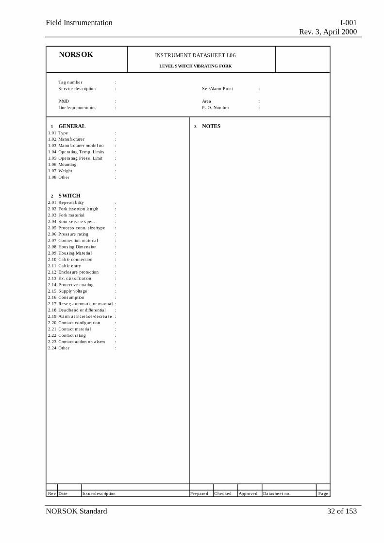
NORSOK INSTRUMENT DATASHEET L06
LEVEL SWITCH VIBRATING FORK
Tag number :Se rvice description : Se t/Ala rm P oint :
P&ID : Area :Line/equipment no. : P . O. Number :
1 GENERAL 3 NOTES1.01 Type :1.02 Manufacture r :1.03 Manufacture r mode l no :1.04 Operating Temp. Limits :1.05 Operating Pres s . Limit :1.06 Mounting :1.07 Weight :1.08 Other :
2 SWITCH2.01 Repea tability :2.02 Fork inse rtion length :2.03 Fork materia l :2.04 Sour se rvice spec. :2.05 Process conn. s ize /type :2.06 Pressure ra ting :2.07 Connection mate ria l :2.08 Hous ing Dimens ion :2.09 Hous ing Mate ria l :2.10 Cable connection :2.11 Cable entry :2.12 Enclosure protection :2.13 Ex. cla s s ifica tion :2.14 Protective coa ting :2.15 Supply voltage :2.16 Consumption :2.17 Rese t; automatic or manual :2.18 Deadband or differentia l :2.19 Ala rm a t increase/decrease :2.20 Contact configura tion :2.21 Contact ma te ria l :2.22 Contact ra ting :2.23 Contact action on alarm :2.24 Other :
Rev Date Is sue/description Prepared Checked Approved Datasheet no. Page
Field Instrumentation I-001Rev. 3, April 2000
NORSOK Standard 33 of 153
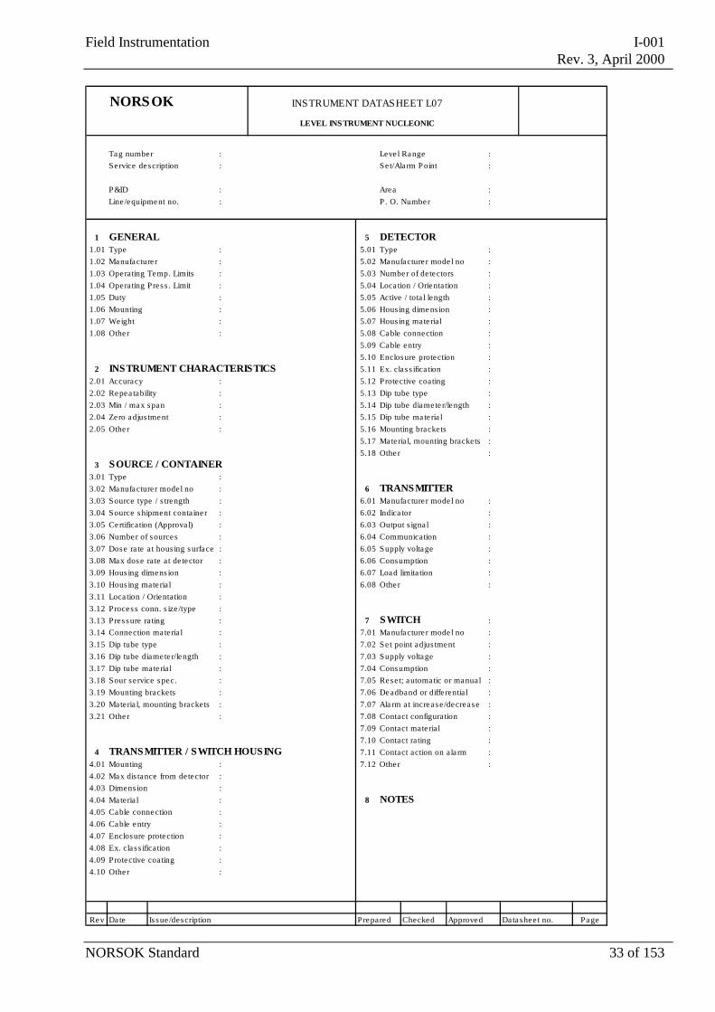
NORSOK INSTRUMENT DATASHEET L07
LEVEL INS TRUMENT NUCLEONIC
Tag number : Leve l Range :Service description : Se t/Ala rm P oint :
P&ID : Area :Line /equipment no. : P . O. Number :
1 GENERAL 5 DETECTOR1.01 Type : 5.01 Type :1.02 Manufacture r : 5.02 Manufacture r mode l no :1.03 Operating Temp. Limits : 5.03 Number of detectors :1.04 Operating Pres s . Limit : 5.04 Loca tion / Orientation :1.05 Duty : 5.05 Active / tota l length :1.06 Mounting : 5.06 Hous ing dimens ion :1.07 Weight : 5.07 Hous ing mate ria l :1.08 Other : 5.08 Cable connection :
5.09 Cable entry :5.10 Enclosure protection :
2 INSTRUMENT CHARACTERISTICS 5.11 Ex. cla s s ification :2.01 Accuracy : 5.12 Protective coating :2.02 Repea tability : 5.13 Dip tube type :2.03 Min / max span : 5.14 Dip tube diamete r/length :2.04 Zero adjus tment : 5.15 Dip tube ma te ria l :2.05 Other : 5.16 Mounting brackets :
5.17 Materia l, mounting brackets :5.18 Other :
3 SOURCE / CONTAINER3.01 Type :3.02 Manufacture r mode l no : 6 TRANSMITTER3.03 Source type / s trength : 6.01 Manufacture r mode l no :3.04 Source s hipment containe r : 6.02 Indica tor :3.05 Certification (Approva l) : 6.03 Output s igna l :3.06 Number of sources : 6.04 Communication :3.07 Dose ra te a t hous ing surface : 6.05 Supply voltage :3.08 Max dose rate a t de tector : 6.06 Consumption :3.09 Hous ing dimens ion : 6.07 Load limita tion :3.10 Hous ing mate ria l : 6.08 Other :3.11 Loca tion / Orientation :3.12 Process conn. s ize /type :3.13 Pressure ra ting : 7 SWITCH :3.14 Connection ma te ria l : 7.01 Manufacture r mode l no :3.15 Dip tube type : 7.02 Se t point adjus tment :3.16 Dip tube diamete r/length : 7.03 Supply voltage :3.17 Dip tube ma te ria l : 7.04 Consumption :3.18 Sour service spec. : 7.05 Reset; automatic or manual :3.19 Mounting brackets : 7.06 Deadband or diffe rentia l :3.20 Materia l, mounting brackets : 7.07 Ala rm at increase/decrease :3.21 Other : 7.08 Contact configura tion :
7.09 Contact mate ria l :7.10 Contact ra ting :
4 TRANSMITTER / SWITCH HOUSING 7.11 Contact action on ala rm :4.01 Mounting : 7.12 Other :4.02 Max dis tance from de tector :4.03 Dimens ion :4.04 Materia l : 8 NOTES4.05 Cable connection :4.06 Cable entry :4.07 Enclosure protection :4.08 Ex. cla s s ification :4.09 Protective coating :4.10 Other :
Rev Date Is sue /description Prepared Checked Approved Datashee t no. Page
Field Instrumentation I-001Rev. 3, April 2000
NORSOK Standard 34 of 153
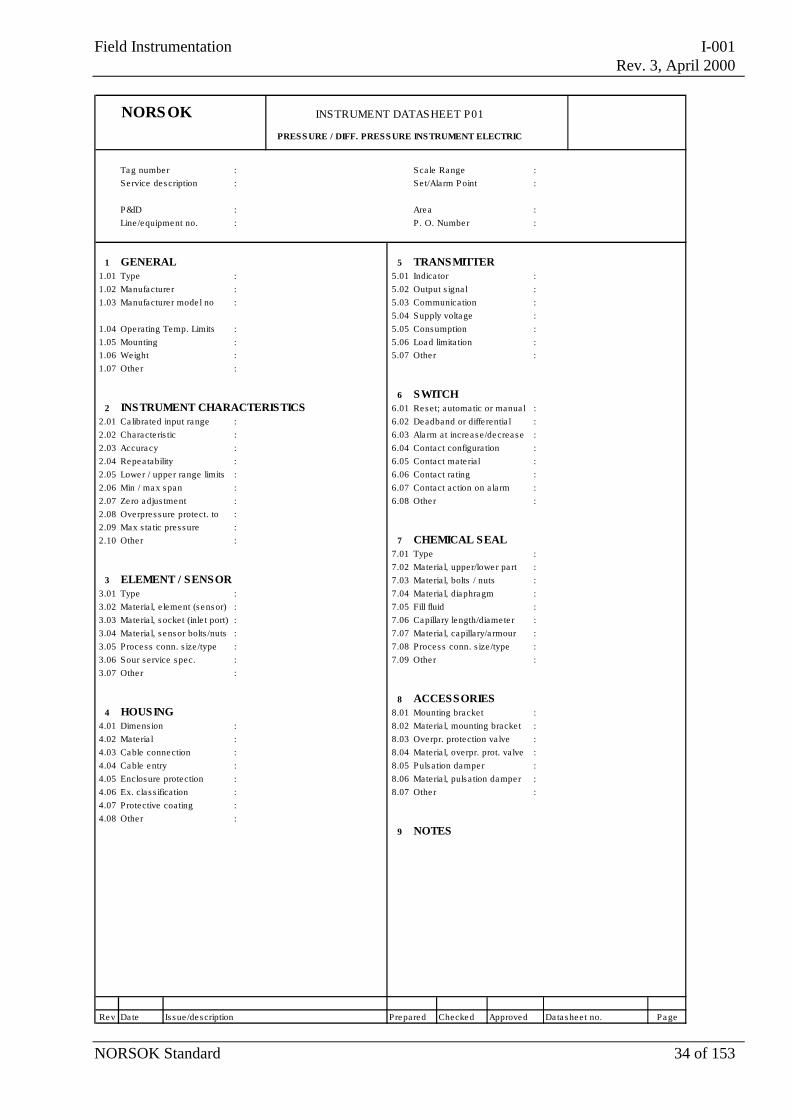
NORSOK INSTRUMENT DATASHEET P01
PRESS URE / DIFF. PRESS URE INSTRUMENT ELECTRIC
Tag number : Scale Range :Service description : Se t/Alarm P oint :
P&ID : Area :Line /equipment no. : P . O. Number :
1 GENERAL 5 TRANSMITTER1.01 Type : 5.01 Indica tor :1.02 Manufacture r : 5.02 Output s igna l :1.03 Manufacture r mode l no : 5.03 Communication :
5.04 Supply voltage :1.04 Operating Temp. Limits : 5.05 Consumption :1.05 Mounting : 5.06 Load limita tion :1.06 Weight : 5.07 Other :1.07 Other :
6 SWITCH2 INSTRUMENT CHARACTERISTICS 6.01 Reset; automatic or manua l :
2.01 Ca librated input range : 6.02 Deadband or diffe rentia l :2.02 Characte ris tic : 6.03 Ala rm at increase/decrease :2.03 Accuracy : 6.04 Contact configura tion :2.04 Repea tability : 6.05 Contact mate ria l :2.05 Lower / upper range limits : 6.06 Contact ra ting :2.06 Min / max span : 6.07 Contact action on a la rm :2.07 Zero adjus tment : 6.08 Other :2.08 Overpres sure protect. to :2.09 Max s ta tic pres sure :2.10 Other : 7 CHEMICAL SEAL
7.01 Type :7.02 Materia l, upper/lower pa rt :
3 ELEMENT / SENSOR 7.03 Materia l, bolts / nuts :3.01 Type : 7.04 Materia l, diaphragm :3.02 Materia l, e lement (sensor) : 7.05 Fill fluid :3.03 Materia l, socket (inle t port) : 7.06 Capillary length/diamete r :3.04 Materia l, s ensor bolts /nuts : 7.07 Materia l, capillary/a rmour :3.05 Process conn. s ize /type : 7.08 Process conn. s ize /type :3.06 Sour service spec. : 7.09 Other :3.07 Other :
8 ACCESSORIES4 HOUSING 8.01 Mounting bracket :
4.01 Dimens ion : 8.02 Materia l, mounting bracke t :4.02 Materia l : 8.03 Overpr. protection va lve :4.03 Cable connection : 8.04 Materia l, overpr. prot. valve :4.04 Cable entry : 8.05 Pulsa tion damper :4.05 Enclosure protection : 8.06 Materia l, pulsa tion damper :4.06 Ex. cla s s ification : 8.07 Other :4.07 Protective coating :4.08 Other :
9 NOTES
Rev Date Is sue /description Prepared Checked Approved Datasheet no. Page

Field Instrumentation I-001Rev. 3, April 2000
NORSOK Standard 35 of 153
NORSOK INSTRUMENT DATASHEET P02
PRESS URE / DIFF. PRES SURE INDICATOR
Tag number : Scale Range :Service description :
P&ID : Area :Line /equipment no. : P . O. Number :
1 GENERAL 5 CHEMICAL SEAL1.01 Type : 5.01 Type :1.02 Manufacture r : 5.02 Materia l, upper/lower pa rt :1.03 Manufacture r mode l no : 5.03 Materia l, bolts / nuts :
5.04 Materia l, diaphragm :1.04 Operating Temp. Limits : 5.05 Fill fluid :1.05 Mounting : 5.06 Capillary length/diamete r :1.06 Weight : 5.07 Materia l, capillary/armour :1.07 Other : 5.08 Process conn. s ize /type :
5.09 Other :
2 INSTRUMENT CHARACTERISTICS 2.01 Ca librated input range : 6 ACCESSORIES2.02 Characte ris tic : 6.01 Mounting bracket :2.03 Accuracy : 6.02 Materia l, mounting bracket :2.04 Repea tability : 6.03 Overpr. protection valve :2.05 Overpres sure protect. to : 6.04 Materia l, overpr. prot. va lve :2.06 Max s ta tic pres sure : 6.05 Pulsa tion damper :2.07 Other : 6.06 Materia l, pulsa tion damper :
6.07 Other :
3 ELEMENT / SENSOR3.01 Type : 7 NOTES3.02 Materia l, e lement (s ensor) :3.03 Materia l, socket (inle t port) :3.04 Materia l, s ensor bolts /nuts :3.05 Process conn. s ize /type :3.06 Pos ition of connection :3.07 Sour service spec. :3.08 Other :
4 HOUSING4.01 Nomina l s ize :4.02 Materia l :4.03 Enclosure protection :4.04 Markings and sca le color :4.05 Pointer color :4.06 Scale length or de flection :4.07 Glass type :4.08 Fill fluid :4.09 Blow-out protection :4.10 Other :
Rev Date Is sue /description Prepared Checked Approved Datashee t no. Page
Field Instrumentation I-001Rev. 3, April 2000
NORSOK Standard 36 of 153
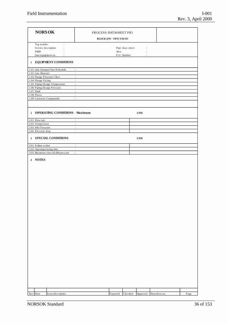
NORSOK PROCESS DATASHEET PR1
BLOCK (ON - OFF) VALVE
Tag number :Service des cription : P ipe clas s shee t :P&ID : Area :Line /equipment no. : P .O. Number :
1 EQUIPMENT CONDITIONS
1.01 Line Nomina l S ize /S chedule :1.02 Line Materia l :1.03 Flange P ress ure Clas s :1.04 Flange Facing :1.05 Piping Des ign Tempera ture :1.06 Piping Des ign P ress ure :1.07 Fluid :1.08 Phas e :1.09 Corros ive Compounds :
2 OPERATING CONDITIONS - Maximum UNIT
2.01 Flow ra te :2.02 Tempera ture :2.03 Inle t Pres sure :2.04 Pres sure drop :
3 SPECIAL CONDITIONS UNIT
3.01 Failure action :3.02 Opening/clos ing time :3.03 Maximum shut-off diff-press ure :
4 NOTES
Rev Date Is sue /des cription Prepared Checked Approved Datas hee t no. Page
Field Instrumentation I-001Rev. 3, April 2000
NORSOK Standard 37 of 153
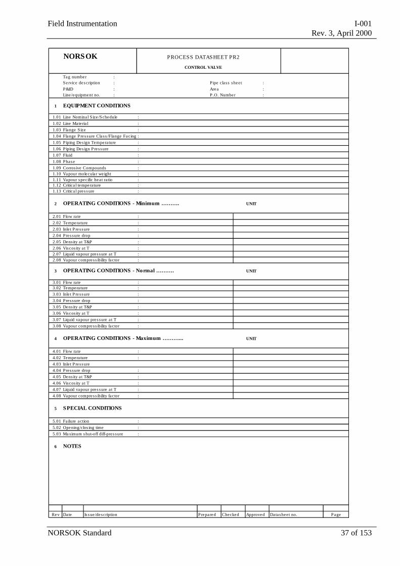
NORSOK PROCESS DATASHEET PR2
CONTROL VALVE
Tag number :Service des cription : P ipe class s hee t :P&ID : Area :Line /equipment no. : P .O. Number :
1 EQUIPMENT CONDITIONS
1.01 Line Nomina l S ize /S chedule :1.02 Line Materia l :1.03 Flange S ize :1.04 Flange Pres sure Class /Flange Facing :1.05 Piping Des ign Tempera ture :1.06 Piping Des ign P ress ure :1.07 Fluid :1.08 Phas e :1.09 Corros ive Compounds :1.10 Vapour molecula r weight :1.11 Vapour specific hea t ra tio :1.12 Critica l tempera ture :1.13 Critica l pres s ure :
2 OPERATING CONDITIONS - Minimum ………. UNIT
2.01 Flow ra te :2.02 Tempera ture :2.03 Inle t P ress ure :2.04 Pres sure drop :2.05 Dens ity a t T&P :2.06 Viscos ity a t T :2.07 Liquid vapour pres sure a t T :2.08 Vapour compress ibility factor :
3 OPERATING CONDITIONS - Normal ………. UNIT
3.01 Flow ra te :3.02 Tempera ture :3.03 Inle t P ress ure :3.04 Pres sure drop :3.05 Dens ity a t T&P :3.06 Viscos ity a t T :3.07 Liquid vapour pres sure a t T :3.08 Vapour compress ibility factor :
4 OPERATING CONDITIONS - Maximum ………... UNIT
4.01 Flow ra te :4.02 Tempera ture :4.03 Inle t P ress ure4.04 Pres sure drop :4.05 Dens ity a t T&P :4.06 Viscos ity a t T :4.07 Liquid vapour pres sure a t T :4.08 Vapour compress ibility factor :
5 SPECIAL CONDITIONS
5.01 Failure action :5.02 Opening/clos ing time :5.03 Maximum s hut-off diff-pres sure :
6 NOTES
Rev Date Is s ue /description Prepared Checked Approved Datas hee t no. Page
Field Instrumentation I-001Rev. 3, April 2000
NORSOK Standard 38 of 153
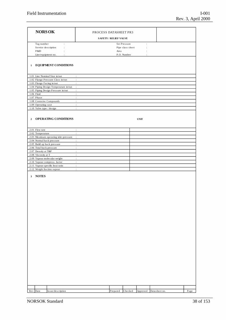
NORSOK PROCESS DATASHEET PR3
SAFETY / RELIEF VALVE
Tag number : Se t Pres sure :Service des cription : P ipe clas s shee t :P&ID : Area :Line /equipment no. : P .O. Number :
1 EQUIPMENT CONDITIONS
1.01 Line Nomina l S ize in/out :1.02 Flange P res sure Clas s in/out :1.03 Flange Facing in/out :1.04 Piping Des ign Tempera ture in/out :1.05 Piping Des ign P ress ure in/out :1.06 Fluid :1.07 Phas e :1.08 Corros ive Compounds :1.09 Opera ting case :1.10 Valve type / des ign :
2 OPERATING CONDITIONS UNIT
2.01 Flow ra te :2.02 Tempera ture :2.03 Maximum opera ting inle t pres sure :2.04 Normal back pres sure :2.05 Build up back press ure :2.06 Tota l back press ure :2.07 Dens ity at T&P :2.08 Viscos ity a t T :2.09 Vapour molecula r weight :2.10 Vapour compress . factor :2.11 Vapour s pecific hea t ra tio :2.12 Weight fraction vapour :
3 NOTES
Rev Date Is sue /des cription Prepared Checked Approved Datas hee t no. Page
Field Instrumentation I-001Rev. 3, April 2000
NORSOK Standard 39 of 153
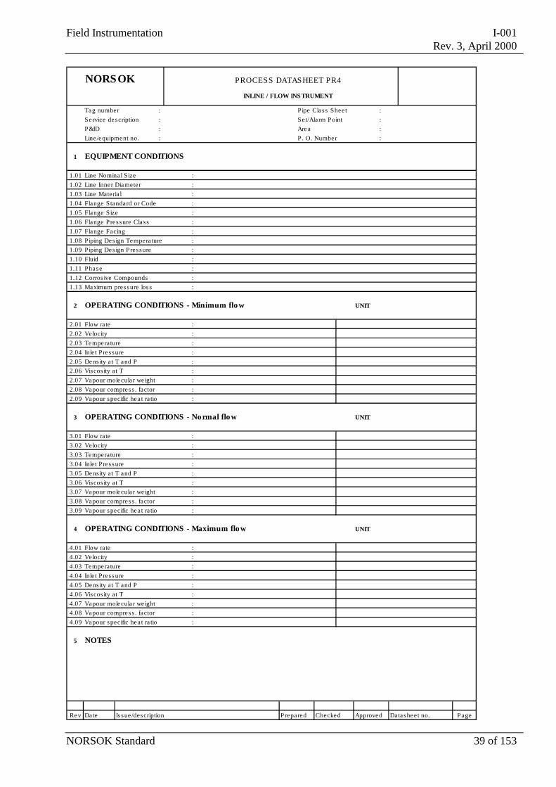
NORSOK PROCESS DATASHEET PR4
INLINE / FLOW INSTRUMENT
Tag number : P ipe Clas s Shee t :Se rvice description : Se t/Ala rm P oint :P&ID : Area :Line /equipment no. : P . O. Number :
1 EQUIPMENT CONDITIONS
1.01 Line Nomina l S ize :1.02 Line Inner Diamete r :1.03 Line Materia l :1.04 Flange S tandard or Code :1.05 Flange S ize :1.06 Flange Pres sure Clas s :1.07 Flange Facing :1.08 Piping Des ign Tempera ture :1.09 Piping Des ign P res sure :1.10 Fluid :
1.11 Phase : 1.12 Corros ive Compounds : 1.13 Maximum pres sure los s :
2 OPERATING CONDITIONS - Minimum flow UNIT
2.01 Flow rate :2.02 Velocity :2.03 Temperature :2.04 Inlet Pres sure :2.05 Dens ity a t T and P :2.06 Viscos ity a t T :2.07 Vapour molecular we ight :2.08 Vapour compress . factor :2.09 Vapour specific hea t ra tio :
3 OPERATING CONDITIONS - Normal flow UNIT
3.01 Flow rate :3.02 Velocity :3.03 Temperature :3.04 Inlet Pres sure :3.05 Dens ity a t T and P :3.06 Viscos ity a t T :3.07 Vapour molecular we ight :3.08 Vapour compress . factor :3.09 Vapour specific hea t ra tio :
4 OPERATING CONDITIONS - Maximum flow UNIT
4.01 Flow rate :4.02 Velocity :4.03 Temperature :4.04 Inlet Pres sure :4.05 Dens ity a t T and P :4.06 Viscos ity a t T :4.07 Vapour molecular we ight :4.08 Vapour compress . factor :4.09 Vapour specific hea t ra tio :
5 NOTES
Rev Date Is sue /description Prepared Checked Approved Datashee t no. Page
Field Instrumentation I-001Rev. 3, April 2000
NORSOK Standard 40 of 153
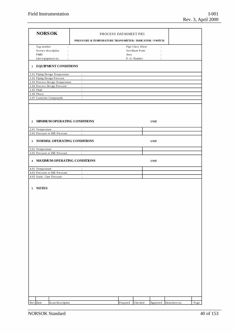
NORSOK PROCESS DATASHEET PR5
PRESS URE & TEMPERATURE TRANSMITTER / INDICATOR / S WITCH
Tag number : P ipe Clas s Shee t :Se rvice description : Se t/Ala rm P oint :P&ID : Area :Line /equipment no. : P . O. Number :
1 EQUIPMENT CONDITIONS
1.01 Piping Des ign Tempera ture :1.02 Piping Des ign P res sure :1.03 Process Des ign Temperature :1.04 Process Des ign P res sure :1.05 Fluid :1.06 Phase :1.07 Corros ive Compounds :
2 MINIMUM OPERATING CONDITIONS UNIT
2.01 Temperature :2.02 Pressure or Diff. Pres sure :
3 NORMAL OPERATING CONDITIONS UNIT
3.01 Temperature :3.02 Pressure or Diff. Pres sure :
4 MAXIMUM OPERATING CONDITIONS UNIT
4.01 Temperature :4.02 Pressure or Diff. Pres sure :4.03 Static / Line P res sure :
5 NOTES
Rev Date Is sue /description Prepared Checked Approved Datashee t no. Page
Field Instrumentation I-001Rev. 3, April 2000
NORSOK Standard 41 of 153
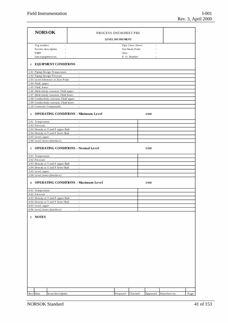
NORSOK PROCESS DATASHEET PR6
LEVEL INS TRUMENT
Tag number : P ipe Clas s Shee t :Se rvice description : Se t/Ala rm P oint :P&ID : Area :Line /equipment no. : P . O. Number :
1 EQUIPMENT CONDITIONS
1.01 Piping Des ign Tempera ture :1.02 Piping Des ign P res sure :1.03 Leve l reference or Zero P oint :1.04 Fluid, upper :1.05 Fluid, lower :1.06 Die lectricity cons tant, Fluid upper :1.07 Die lectricity cons tant, Fluid lower :1.08 Conductivity cons tant, Fluid upper :1.09 Conductivity cons tant, Fluid lower :1.10 Corros ive Compounds :
2 OPERATING CONDITIONS - Minimum Level UNIT
2.01 Temperature :2.02 Pressure :2.03 Dens ity a t T and P upper fluid :2.04 Dens ity a t T and P lower fluid :2.05 Leve l, upper :2.06 Leve l, lower (inte rface ) :
3 OPERATING CONDITIONS - Normal Level UNIT
3.01 Temperature :3.02 Pressure :3.03 Dens ity a t T and P upper fluid :3.04 Dens ity a t T and P lower fluid :3.05 Leve l, upper :3.06 Leve l, lower (inte rface ) :
4 OPERATING CONDITIONS - Maximum Level UNIT
4.01 Temperature :4.02 Pressure :4.03 Dens ity a t T and P upper fluid :4.04 Dens ity a t T and P lower fluid :4.05 Leve l, upper :4.06 Leve l, lower (inte rface ) :
5 NOTES
Rev Date Is sue /description Prepared Checked Approved Datashee t no. Page
Field Instrumentation I-001Rev. 3, April 2000
NORSOK Standard 42 of 153
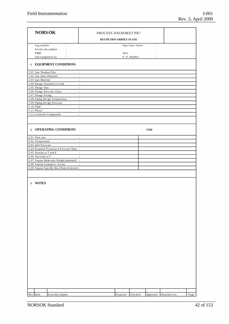
NORSOK PROCESS DATASHEET PR7
RESTICTION ORIFICE PLATE
Tag number : P ipe Clas s Shee t :Se rvice description :P&ID : Area :Line /equipment no. : P . O. Number :
1 EQUIPMENT CONDITIONS
1.01 Line Nomina l S ize :1.02 Line Inner Diamete r :1.03 Line Materia l :1.04 Flange S tandard or Code :1.05 Flange S ize :1.06 Flange Pres sure Clas s :1.07 Flange Facing :1.08 Piping Des ign Tempera ture :1.09 Piping Des ign P res sure :1.10 Fluid :1.11 Phase :1.12 Corros ive Compounds :
2 OPERATING CONDITIONS UNIT
2.01 Flow rate :2.02 Temperature :2.03 Inlet Pres sure :2.04 Required P ermanent Pres sure Drop :2.05 Dens ity a t T and P :2.06 Viscos ity a t T :2.07 Vapour Molecular Weight (optional) :2.08 Vapour Compress . Factor :2.09 Vapour S pecific Heat Ra tio (k-factor) :
3 NOTES
Rev Date Is sue /description Prepared Checked Approved Datashee t no. Page
Field Instrumentation I-001Rev. 3, April 2000
NORSOK Standard 43 of 153
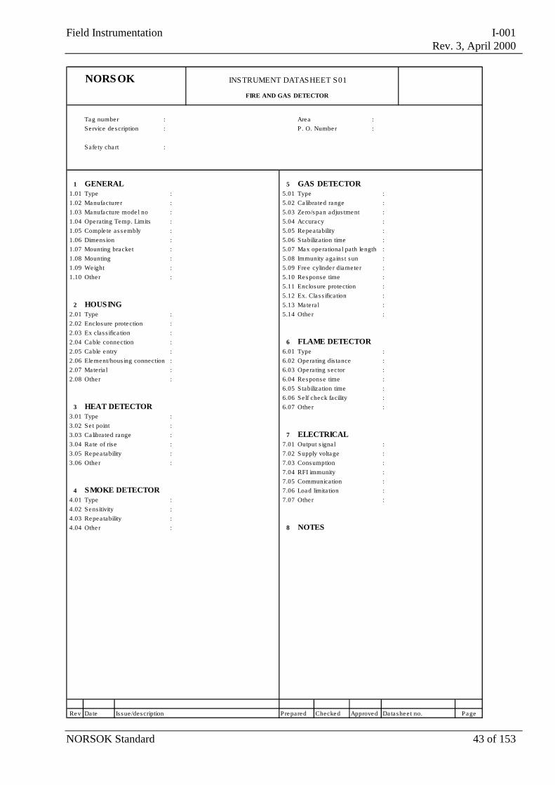
NORSOK INSTRUMENT DATASHEET S01
FIRE AND GAS DETECTOR
Tag number : Area :Se rvice description : P . O. Number :
Sa fe ty cha rt :
1 GENERAL 5 GAS DETECTOR1.01 Type : 5.01 Type :1.02 Manufacture r : 5.02 Ca librated range :1.03 Manufacture mode l no : 5.03 Zero/span adjus tment :1.04 Operating Temp. Limits : 5.04 Accuracy :1.05 Comple te as s embly : 5.05 Repea tability :1.06 Dimens ion : 5.06 Stabilization time :1.07 Mounting bracket : 5.07 Max operationa l path length :1.08 Mounting : 5.08 Immunity aga ins t sun :1.09 Weight : 5.09 Free cylinde r diamete r :1.10 Other : 5.10 Response time :
5.11 Enclosure protection :5.12 Ex. Clas s ification :
2 HOUSING 5.13 Matera l :2.01 Type : 5.14 Other :2.02 Enclosure protection :2.03 Ex clas s ifica tion :2.04 Cable connection : 6 FLAME DETECTOR2.05 Cable entry : 6.01 Type :2.06 Element/hous ing connection : 6.02 Operating dis tance :2.07 Materia l : 6.03 Operating sector :2.08 Other : 6.04 Response time :
6.05 Stabilization time :6.06 Se lf check facility :
3 HEAT DETECTOR 6.07 Other :3.01 Type : 3.02 Se t point :3.03 Ca librated range : 7 ELECTRICAL3.04 Ra te of ris e : 7.01 Output s igna l :3.05 Repea tability : 7.02 Supply voltage :3.06 Other : 7.03 Consumption :
7.04 RFI immunity :7.05 Communication :
4 SMOKE DETECTOR 7.06 Load limita tion :4.01 Type : 7.07 Other :4.02 Sens itivity :4.03 Repea tability :4.04 Other : 8 NOTES
Rev Date Is sue /description Prepared Checked Approved Datashee t no. Page
Field Instrumentation I-001Rev. 3, April 2000
NORSOK Standard 44 of 153
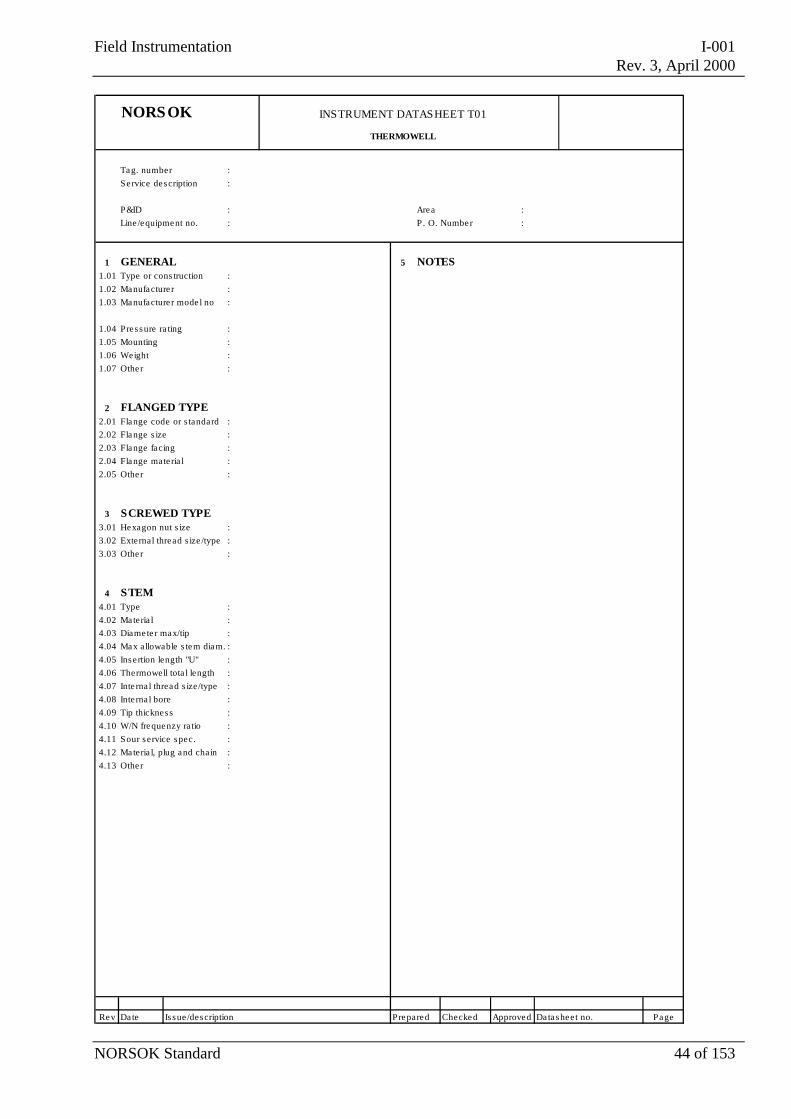
NORSOK INSTRUMENT DATASHEET T01
THERMOWELL
Tag. number :Se rvice description :
P&ID : Area :Line /equipment no. : P . O. Number :
1 GENERAL 5 NOTES1.01 Type or cons truction : 1.02 Manufacture r :1.03 Manufacture r mode l no :
1.04 Pressure ra ting :1.05 Mounting :1.06 Weight : 1.07 Other :
2 FLANGED TYPE
2.01 Flange code or s tandard :2.02 Flange s ize : 2.03 Flange facing :2.04 Flange mate ria l :2.05 Other :
3 SCREWED TYPE3.01 Hexagon nut s ize :3.02 External thread s ize /type : 3.03 Other :
4 STEM4.01 Type :4.02 Materia l :4.03 Diamete r max/tip :4.04 Max allowable s tem diam. :4.05 Inse rtion length "U" :4.06 Thermowell tota l length :4.07 Inte rna l thread s ize/type :4.08 Inte rna l bore :4.09 Tip thickness :4.10 W/N frequenzy ratio :4.11 Sour service spec. :4.12 Materia l, plug and chain :4.13 Other :
Rev Date Is sue /description Prepared Checked Approved Datasheet no. Page
Field Instrumentation I-001Rev. 3, April 2000
NORSOK Standard 45 of 153
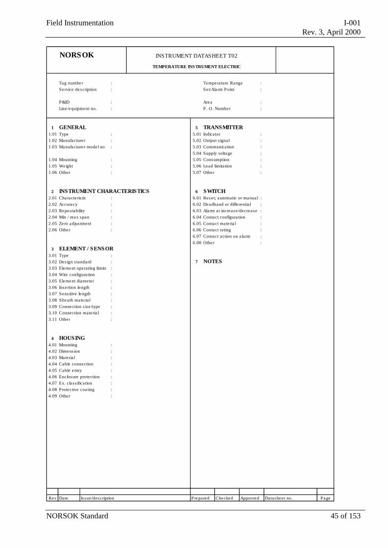
NORSOK INSTRUMENT DATASHEET T02
TEMPERATURE INS TRUMENT ELECTRIC
Tag number : Temperature Range :Service description : Se t/Ala rm P oint :
P&ID : Area :Line/equipment no. : P . O. Number :
1 GENERAL 5 TRANSMITTER1.01 Type : 5.01 Indicator :1.02 Manufacture r : 5.02 Output s ignal :1.03 Manufacture r mode l no : 5.03 Communica tion :
5.04 Supply voltage :1.04 Mounting : 5.05 Consumption :1.05 Weight : 5.06 Load limita tion :1.06 Other : 5.07 Other :
2 INSTRUMENT CHARACTERISTICS 6 SWITCH2.01 Characte ris tic : 6.01 Rese t; automatic or manual :2.02 Accuracy : 6.02 Deadband or diffe rentia l :2.03 Repea tability : 6.03 Ala rm a t increase/decrease :2.04 Min / max span : 6.04 Contact configura tion :2.05 Zero adjus tment : 6.05 Contact ma te ria l :2.06 Other : 6.06 Contact ra ting :
6.07 Contact action on a larm :6.08 Other :
3 ELEMENT / SENSOR3.01 Type :3.02 Des ign s tandard : 7 NOTES3.03 Element operating limits :3.04 Wire configura tion :3.05 Element diameter :3.06 Insertion length :3.07 Sens itive length :3.08 Shea th ma teria l :3.09 Connection s ize/type :3.10 Connection mate ria l :3.11 Other :
4 HOUSING4.01 Mounting :4.02 Dimens ion :4.03 Mate ria l :4.04 Cable connection :4.05 Cable entry :4.06 Enclosure protection :4.07 Ex. cla s s ifica tion :4.08 Protective coa ting :4.09 Other :
Rev Date Is sue/description Prepared Checked Approved Datasheet no. Page
Field Instrumentation I-001Rev. 3, April 2000
NORSOK Standard 46 of 153
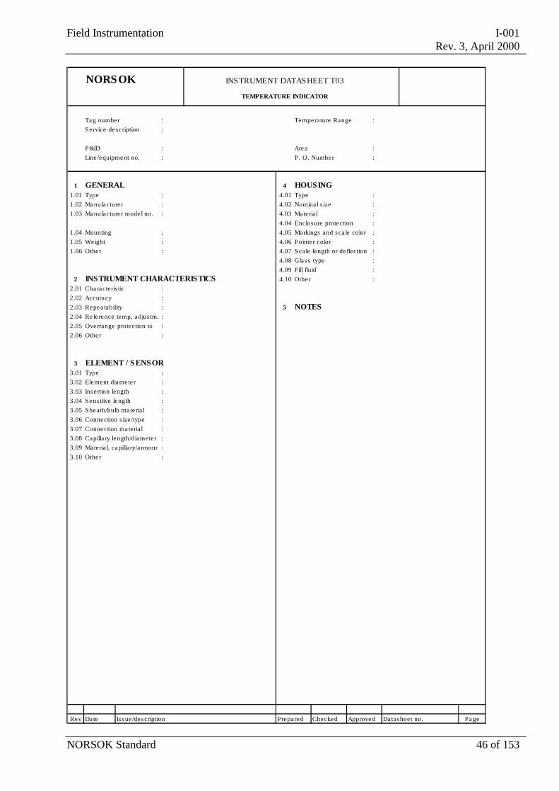
NORSOK INSTRUMENT DATASHEET T03
TEMPERATURE INDICATOR
Tag number : Temperature Range :Service description :
P&ID : Area :Line /equipment no. : P . O. Number :
1 GENERAL 4 HOUSING1.01 Type : 4.01 Type :1.02 Manufacture r : 4.02 Nomina l s ize :1.03 Manufacture r mode l no. : 4.03 Materia l :
4.04 Enclosure protection :1.04 Mounting : 4.05 Markings and sca le color :1.05 Weight : 4.06 Pointer color :1.06 Other : 4.07 Scale length or de flection :
4.08 Glass type :4.09 Fill fluid :
2 INSTRUMENT CHARACTERISTICS 4.10 Other :2.01 Characte ris tic : 2.02 Accuracy :2.03 Repea tability : 5 NOTES2.04 Refe rence temp. adjus tm. :2.05 Overrange protection to :2.06 Other :
3 ELEMENT / SENSOR3.01 Type :3.02 Element diamete r : 3.03 Inse rtion length :3.04 Sens itive length :3.05 Sheath/bulb ma te ria l :3.06 Connection s ize /type :3.07 Connection ma te ria l :3.08 Capillary length/diamete r :3.09 Materia l, capillary/a rmour :3.10 Other :
Rev Date Is sue /description Prepared Checked Approved Datasheet no. Page
Field Instrumentation I-001Rev. 3, April 2000
NORSOK Standard 47 of 153
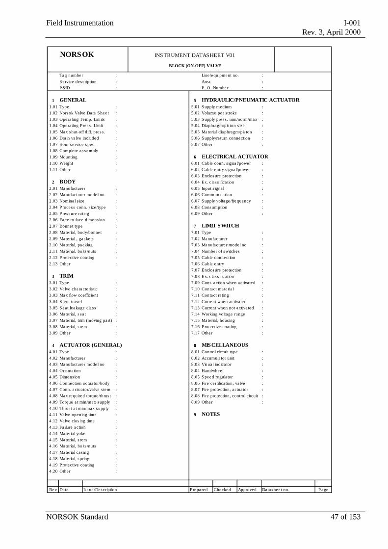
NORSOK INSTRUMENT DATASHEET V01
BLOCK (ON-OFF) VALVE
Tag number : Line /equipment no. :Service description : Area :P&ID : P . O. Number :
1 GENERAL 5 HYDRAULIC/PNEUMATIC ACTUATOR1.01 Type : 5.01 Supply medium :1.02 Nors ok Valve Data Shee t : 5.02 Volume per s troke :1.03 Opera ting Temp. Limits : 5.03 Supply press . min/norm/max :1.04 Opera ting Press . Limit : 5.04 Diaphragm/pis ton s ize :1.05 Max s hut-off diff. press . : 5.05 Material diaphragm/pis ton :1.06 Drain va lve included : 5.06 Supply/re turn connection :1.07 Sour service spec. : 5.07 Other :1.08 Comple te ass embly :1.09 Mounting : 6 ELECTRICAL ACTUATOR1.10 Weight : 6.01 Cable conn. s igna l/power :1.11 Other : 6.02 Cable entry s igna l/power :
6.03 Enclos ure protection :2 BODY 6.04 Ex. class ifica tion :
2.01 Manufacturer : 6.05 Input s igna l :2.02 Manufacturer model no : 6.06 Communication :2.03 Nominal s ize : 6.07 Supply voltage /frequency :2.04 Proces s conn. s ize /type : 6.08 Consumption :2.05 Press ure ra ting : 6.09 Other :2.06 Face to face dimens ion : 2.07 Bonnet type : 7 LIMIT SWITCH2.08 Material, body/bonnet : 7.01 Type :2.09 Material , gaske ts : 7.02 Manufacturer :2.10 Material, packing : 7.03 Manufacturer model no :2.11 Material, bolts /nuts : 7.04 Number of switches :2.12 Protective coa ting : 7.05 Cable connection :2.13 Other : 7.06 Cable entry :
7.07 Enclos ure protection :3 TRIM 7.08 Ex. class ifica tion :
3.01 Type : 7.09 Cont. action when activa ted :3.02 Valve characteris tic : 7.10 Contact material :3.03 Max flow coefficient : 7.11 Contact ra ting :3.04 S tem trave l : 7.12 Current when activated :3.05 Seat leakage class : 7.13 Current when not activa ted :3.06 Material, sea t : 7.14 Working voltage range :3.07 Material, trim (moving part) : 7.15 Material, hous ing :3.08 Material, s tem : 7.16 Protective coa ting :3.09 Other : 7.17 Other :
4 ACTUATOR (GENERAL) 8 MISCELLANEOUS4.01 Type : 8.01 Control circuit type :4.02 Manufacturer : 8.02 Accumula tor unit :4.03 Manufacturer model no : 8.03 Vis ual indica tor :4.04 Orienta tion : 8.04 Handwheel :4.05 Dimens ion : 8.05 Speed regula tor :4.06 Connection actua tor/body : 8.06 Fire certifica tion, valve :4.07 Conn. actua tor/va lve s tem : 8.07 Fire protection, actua tor :4.08 Max required torque/thrus t : 8.08 Fire protection, control circuit :4.09 Torque a t min/max s upply : 8.09 Other :4.10 Thrus t a t min/max supply :4.11 Valve opening time : 9 NOTES4.12 Valve clos ing time :4.13 Failure action :4.14 Material yoke :4.15 Material, s tem :4.16 Material, bolts /nuts :4.17 Material cas ing :4.18 Material, spring :4.19 Protective coa ting :4.20 Other :
Rev Date Iss ue /Description Prepared Checked Approved Datashee t no. Page
Field Instrumentation I-001Rev. 3, April 2000
NORSOK Standard 48 of 153
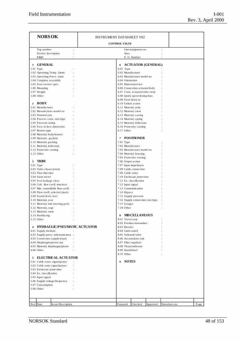
NORSOK INSTRUMENT DATASHEET V02
CONTROL VALVE
Tag number : Line/equipment no. :Se rvice description : Area :P&ID : P . O. Number :
1 GENERAL 6 ACTUATOR (GENERAL)1.01 Type : 6.01 Type :1.02 Opera ting Temp. Limits : 6.02 Manufacturer :1.03 Opera ting Pres s . Limit : 6.03 Manufacturer model no :1.04 Complete a s sembly : 6.04 Orienta tion :1.05 Sour se rvice spec. : 6.05 Dimens ion/s ize :1.06 Mounting : 6.06 Connection actua tor/body :1.07 Weight : 6.07 Conn. actuator/valve s tem :1.08 Othe r : 6.08 Quick open/clos ing func. :
6.09 Push down to :2 BODY 6.10 Failure action :
2.01 Manufacturer : 6.11 Materia l, yoke :2.02 Manufacturer model no : 6.12 Materia l, s tem :2.03 Nominal s ize : 6.13 Materia l, ca s ing :2.04 Process conn. s ize /type : 6.14 Materia l, spring :2.05 Pressure ra ting : 6.15 Materia l, bolts /nuts :2.06 Face to face dimens ion : 6.16 Protective coa ting :2.07 Bonne t type : 6.17 Othe r :2.08 Materia l, body/bonne t :2.09 Materia l , gaske ts : 7 POSITIONER 2.10 Materia l, packing 7.01 Type :2.11 Materia l, bolts /nuts : 7.02 Manufacturer :2.12 Protective coa ting : 7.03 Manufacturer model no :2.13 Othe r : 7.04 Materia l, hous ing :
7.05 Protective coa ting :3 TRIM 7.06 Output action :
3.01 Type : 7.07 Input impedance :3.02 Va lve cha racte ris tic : 7.08 Cable connection :3.03 Flow direction : 7.09 Cable entry :3.04 Stem trave l : 7.10 Enclosure protection :3.05 Seat leakage cla s s : 7.11 Ex. cla s s ification :3.06 Calc. flow coeff. min/max : 7.12 Input s ignal :3.07 Min. controllable flow coeff. : 7.13 Communica tion :3.08 Flow coeff. s e lected (max) : 7.14 Bypas s :3.09 Sound leve l, max : 7.15 Supply pres sure :3.10 Materia l, s eat : 7.16 Supply connection s ize /type :3.11 Materia l, trim (moving pa rt) : 7.17 Gauges :3.12 Materia l, cage : 7.18 Othe r :3.13 Materia l, s tem :3.14 Hardfacing : 8 MISCELLANEOUS3.15 Othe r : 8.01 Travel s top :
8.02 Pos ition transmitte r :4 HYDRAULIC/PNEUMATIC ACTUATOR 8.03 Boos te r :
4.01 Supply medium : 8.04 Limit switch :4.02 Supply pres s . min/norm/max : 8.05 Solenoid valve :4.03 Connection supply/re turn : 8.06 Accumula tor unit :4.04 Diaphragm/pis ton s ize : 8.07 Filte r regula tor :4.05 Materia l, diaphragm/pis ton : 8.08 Visua l indica tor :4.06 Othe r : 8.09 Handwhee l :
8.10 Othe r :5 ELECTRICAL ACTUATOR
5.01 Cable conn. s igna l/power : 9 NOTES5.02 Cable entry s igna l/power :5.03 Enclosure protection :5.04 Ex. cla s s ification :5.05 Input s ignal :5.06 Supply voltage /frequency :5.07 Consumption :5.08 Othe r :
Rev Date Is sue /Description Prepared Checked Approved Datasheet no. Page
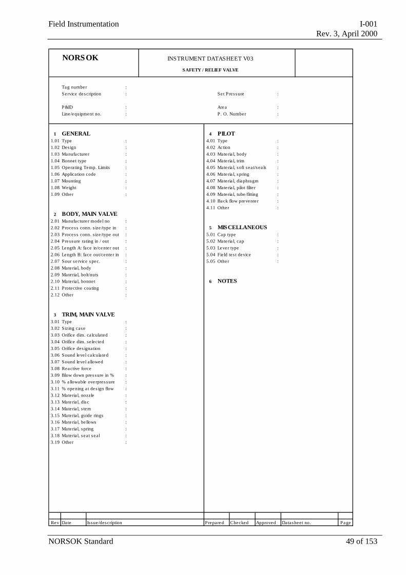
Field Instrumentation I-001Rev. 3, April 2000
NORSOK Standard 49 of 153
NORSOK INSTRUMENT DATASHEET V03
SAFETY / RELIEF VALVE
Tag number :Se rvice description : Se t Pres sure :
P&ID : Area :Line/equipment no. : P . O. Number :
1 GENERAL 4 PILOT1.01 Type : 4.01 Type :1.02 Des ign : 4.02 Action :1.03 Manufacture r : 4.03 Mate ria l, body :1.04 Bonnet type : 4.04 Mate ria l, trim :1.05 Operating Temp. Limits : 4.05 Mate ria l, soft s ea t/s ea ls :1.06 Application code : 4.06 Mate ria l, spring :1.07 Mounting : 4.07 Mate ria l, diaphragm :1.08 Weight : 4.08 Mate ria l, pilot filter :1.09 Other : 4.09 Mate ria l, tube /fitting :
4.10 Back flow prevente r :4.11 Other :
2 BODY, MAIN VALVE2.01 Manufacture r mode l no :2.02 Process conn. s ize /type in : 5 MISCELLANEOUS2.03 Process conn. s ize /type out : 5.01 Cap type :2.04 Pressure rating in / out : 5.02 Mate ria l, cap :2.05 Length A: face in/cente r out : 5.03 Lever type :2.06 Length B: face out/cente r in : 5.04 Field tes t device :2.07 Sour se rvice spec. : 5.05 Other :2.08 Mate ria l, body :2.09 Mate ria l, bolt/nuts :2.10 Mate ria l, bonnet : 6 NOTES2.11 Protective coa ting :2.12 Other :
3 TRIM, MAIN VALVE3.01 Type :3.02 Sizing case :3.03 Orifice dim. ca lculated :3.04 Orifice dim. se lected :3.05 Orifice des ignation :3.06 Sound level calcula ted :3.07 Sound level a llowed :3.08 Reactive force :3.09 Blow down pres sure in % :3.10 % a llowable overpres sure :3.11 % opening a t des ign flow :3.12 Mate ria l, nozzle :3.13 Mate ria l, disc :3.14 Mate ria l, s tem :3.15 Mate ria l, guide rings :3.16 Mate ria l, be llows :3.17 Mate ria l, spring :3.18 Mate ria l, s ea t s eal :3.19 Other :
Rev Date Is sue/description Prepared Checked Approved Datasheet no. Page
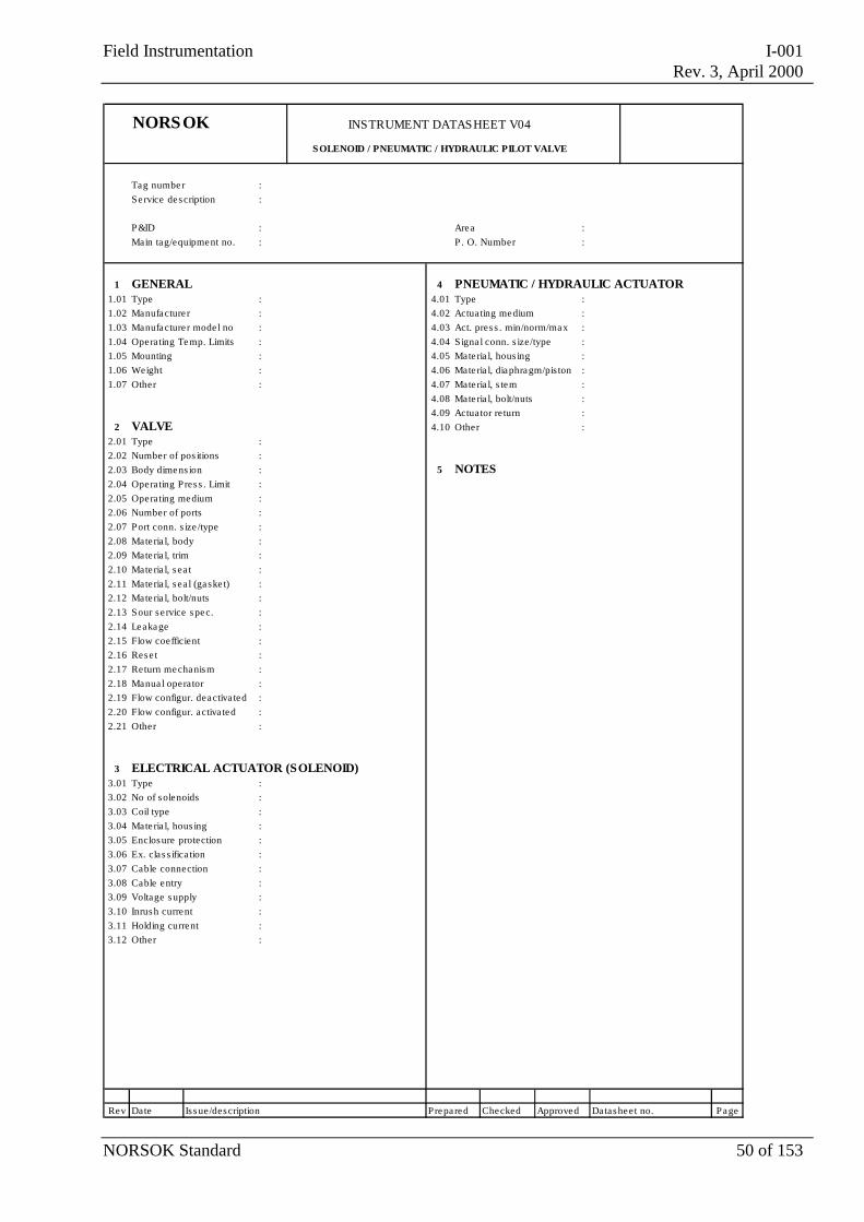
Field Instrumentation I-001Rev. 3, April 2000
NORSOK Standard 50 of 153
NORSOK INSTRUMENT DATASHEET V04
SOLENOID / PNEUMATIC / HYDRAULIC PILOT VALVE
Tag number :Se rvice description :
P&ID : Area :Main tag/equipment no. : P . O. Number :
1 GENERAL 4 PNEUMATIC / HYDRAULIC ACTUATOR1.01 Type : 4.01 Type :1.02 Manufacture r : 4.02 Actuating medium :1.03 Manufacture r mode l no : 4.03 Act. pres s . min/norm/max :1.04 Operating Temp. Limits : 4.04 Signa l conn. s ize/type :1.05 Mounting : 4.05 Mate ria l, hous ing :1.06 Weight : 4.06 Mate ria l, diaphragm/pis ton :1.07 Other : 4.07 Mate ria l, s tem :
4.08 Mate ria l, bolt/nuts :4.09 Actuator re turn :
2 VALVE 4.10 Other :2.01 Type :2.02 Number of pos itions :2.03 Body dimens ion : 5 NOTES2.04 Operating Pres s . Limit :2.05 Operating medium :2.06 Number of ports :2.07 Port conn. s ize /type :2.08 Mate ria l, body :2.09 Mate ria l, trim :2.10 Mate ria l, s ea t :2.11 Mate ria l, s ea l (gaske t) :2.12 Mate ria l, bolt/nuts :2.13 Sour se rvice spec. :2.14 Leakage :2.15 Flow coefficient :2.16 Rese t :2.17 Return mechanism :2.18 Manua l operator :2.19 Flow configur. deactiva ted :2.20 Flow configur. activa ted :2.21 Other :
3 ELECTRICAL ACTUATOR (SOLENOID)3.01 Type :3.02 No of solenoids :3.03 Coil type :3.04 Mate ria l, hous ing :3.05 Enclosure protection :3.06 Ex. cla s s ifica tion :3.07 Cable connection :3.08 Cable entry :3.09 Voltage supply :3.10 Inrush current :3.11 Holding current :3.12 Other :
Rev Date Is sue/description Prepared Checked Approved Datasheet no. Page
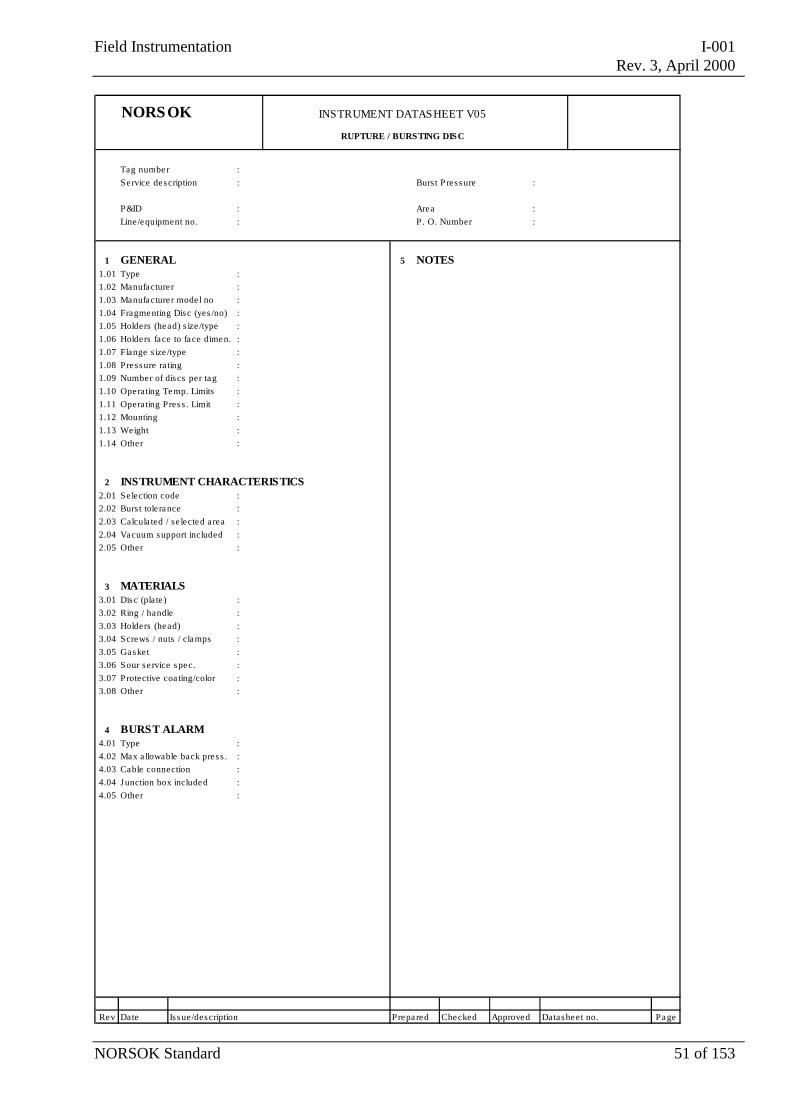
Field Instrumentation I-001Rev. 3, April 2000
NORSOK Standard 51 of 153
NORSOK INSTRUMENT DATASHEET V05
RUPTURE / BURSTING DISC
Tag number :Se rvice description : Burst Pres sure :
P&ID : Area :Line/equipment no. : P . O. Number :
1 GENERAL 5 NOTES1.01 Type :1.02 Manufacture r :1.03 Manufacture r mode l no :1.04 Fragmenting Disc (yes /no) :1.05 Holders (head) s ize /type :1.06 Holders face to face dimen. :1.07 Flange s ize /type :1.08 Pressure ra ting :1.09 Number of discs per tag :1.10 Operating Temp. Limits :1.11 Operating Pres s . Limit :1.12 Mounting :1.13 Weight :1.14 Other :
2 INSTRUMENT CHARACTERISTICS2.01 Se lection code :2.02 Burst tole rance :2.03 Calcula ted / se lected a rea :2.04 Vacuum support included :2.05 Other :
3 MATERIALS3.01 Disc (plate ) :3.02 Ring / handle :3.03 Holders (head) :3.04 Screws / nuts / clamps :3.05 Gasket :3.06 Sour se rvice spec. :3.07 Protective coa ting/color :3.08 Other :
4 BURST ALARM4.01 Type :4.02 Max a llowable back pres s . :4.03 Cable connection :4.04 Junction box included :4.05 Other :
Rev Date Is sue/description Prepared Checked Approved Datasheet no. Page
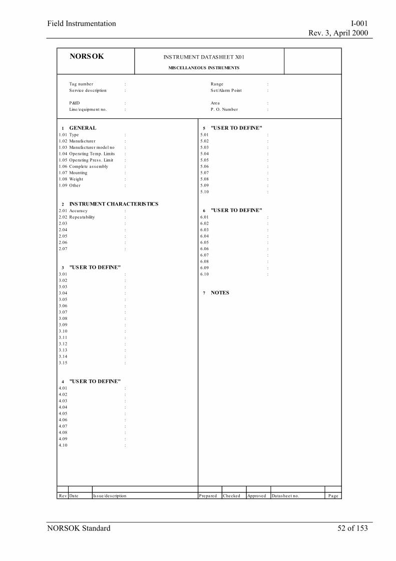
Field Instrumentation I-001 Rev. 3, April 2000
NORSOK Standard 52 of 153
NORSOK INSTRUMENT DATASHEET X01
MISCELLANEOUS INSTRUMENTS
Tag number : Range :Se rvice des cription : Se t/Ala rm Point :
P&ID : Area :Line /equipment no. : P . O. Number :
1 GENERAL 5 "USER TO DEFINE"1.01 Type : 5.01 :1.02 Manufacture r : 5.02 :1.03 Manufacture r model no : 5.03 :1.04 Opera ting Temp. Limits : 5.04 :1.05 Opera ting Pres s . Limit : 5.05 :1.06 Comple te as sembly : 5.06 :1.07 Mounting : 5.07 :1.08 Weight : 5.08 :1.09 Othe r : 5.09 :
5.10 :
2 INSTRUMENT CHARACTERISTICS2.01 Accuracy : 6 "USER TO DEFINE"2.02 Repea tability : 6.01 :2.03 : 6.02 :2.04 : 6.03 :2.05 : 6.04 :2.06 : 6.05 :2.07 : 6.06 :
6.07 :6.08 :
3 "USER TO DEFINE" 6.09 :3.01 : 6.10 :3.02 :3.03 :3.04 : 7 NOTES3.05 :3.06 :3.07 :3.08 :3.09 :3.10 :3.11 :3.12 :3.13 :3.14 :3.15 :
4 "USER TO DEFINE"4.01 :4.02 :4.03 :4.04 :4.05 :4.06 :4.07 :4.08 :4.09 :4.10 :
Rev Date Is sue /description Prepa red Checked Approved Datashee t no. Page
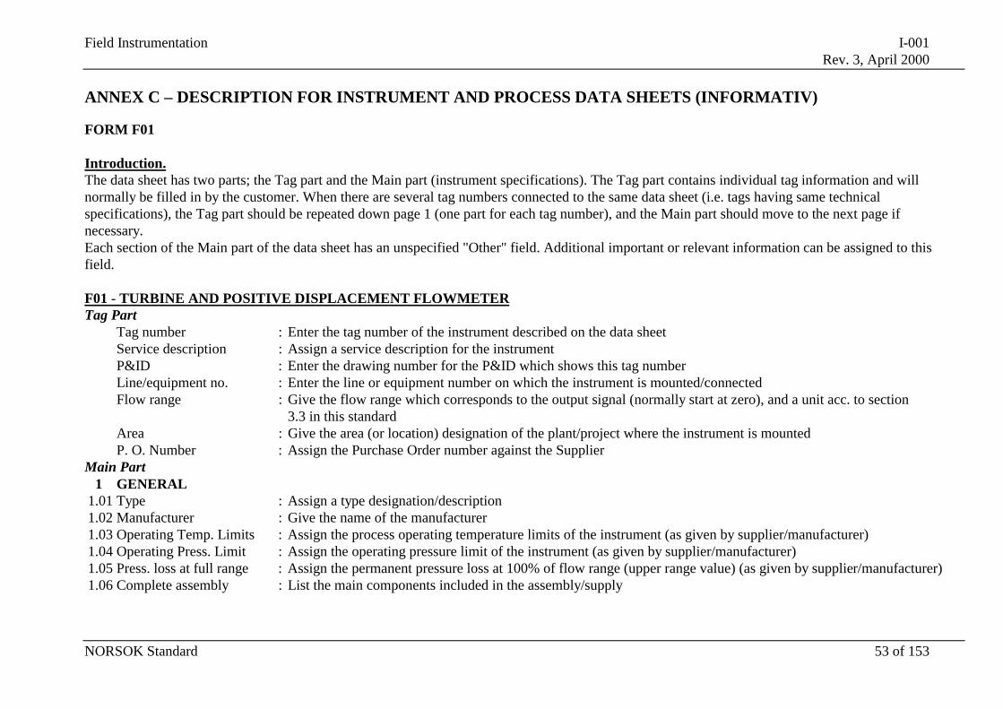
Field Instrumentation I-001Rev. 3, April 2000
NORSOK Standard 53 of 153
ANNEX C – DESCRIPTION FOR INSTRUMENT AND PROCESS DATA SHEETS (INFORMATIV)
FORM F01
Introduction.The data sheet has two parts; the Tag part and the Main part (instrument specifications). The Tag part contains individual tag information and willnormally be filled in by the customer. When there are several tag numbers connected to the same data sheet (i.e. tags having same technicalspecifications), the Tag part should be repeated down page 1 (one part for each tag number), and the Main part should move to the next page ifnecessary.Each section of the Main part of the data sheet has an unspecified "Other" field. Additional important or relevant information can be assigned to thisfield.
F01 - TURBINE AND POSITIVE DISPLACEMENT FLOWMETERTag Part
Tag number : Enter the tag number of the instrument described on the data sheetService description : Assign a service description for the instrumentP&ID : Enter the drawing number for the P&ID which shows this tag numberLine/equipment no. : Enter the line or equipment number on which the instrument is mounted/connectedFlow range : Give the flow range which corresponds to the output signal (normally start at zero), and a unit acc. to section
3.3 in this standardArea : Give the area (or location) designation of the plant/project where the instrument is mountedP. O. Number : Assign the Purchase Order number against the Supplier
Main Part1 GENERAL
1.01 Type : Assign a type designation/description1.02 Manufacturer : Give the name of the manufacturer1.03 Operating Temp. Limits : Assign the process operating temperature limits of the instrument (as given by supplier/manufacturer)1.04 Operating Press. Limit : Assign the operating pressure limit of the instrument (as given by supplier/manufacturer)1.05 Press. loss at full range : Assign the permanent pressure loss at 100% of flow range (upper range value) (as given by supplier/manufacturer)1.06 Complete assembly : List the main components included in the assembly/supply
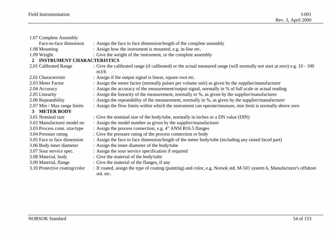
Field Instrumentation I-001Rev. 3, April 2000
NORSOK Standard 54 of 153
1.07 Complete AssemblyFace-to-face dimension : Assign the face to face dimension/length of the complete assembly
1.08 Mounting : Assign how the instrument is mounted, e.g. in-line etc.1.09 Weight : Give the weight of the instrument, or the complete assembly
2 INSTRUMENT CHARACTERISTICS2.01 Calibrated Range : Give the calibrated range (if calibrated) or the actual measured range (will normally not start at zero) e.g. 10 - 100
m3/h2.02 Characteristic : Assign if the output signal is linear, square root etc.2.03 Meter Factor : Assign the meter factor (normally pulses per volume unit) as given by the supplier/manufacturer2.04 Accuracy : Assign the accuracy of the measurement/output signal, normally in % of full scale or actual reading2.05 Linearity : Assign the linearity of the measurement, normally in %, as given by the supplier/manufacturer2.06 Repeatability : Assign the repeatability of the measurement, normally in %, as given by the supplier/manufacturer2.07 Min / Max range limits : Assign the flow limits within which the instrument can operate/measure, min limit is normally above zero
3 METER BODY3.01 Nominal size : Give the nominal size of the body/tube, normally in inches or a DN value (DIN)3.02 Manufacturer model no : Assign the model number as given by the supplier/manufacturer3.03 Process conn. size/type : Assign the process connection, e.g. 4" ANSI B16.5 flanges3.04 Pressure rating : Give the pressure rating of the process connection or body3.05 Face to face dimension : Assign the face to face dimension/length of the meter body/tube (including any raised faced part)3.06 Body inner diameter : Assign the inner diameter of the body/tube3.07 Sour service spec. : Assign the sour service specification if required3.08 Material, body : Give the material of the body/tube3.09 Material, flange : Give the material of the flanges, if any3.10 Protective coating/color : If coated, assign the type of coating (painting) and color, e.g. Norsok std. M-501 system 6, Manufacturer's offshore
std. etc.
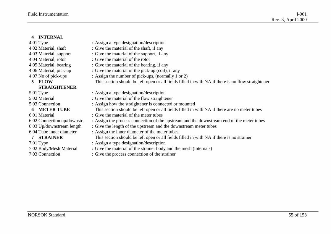
Field Instrumentation I-001Rev. 3, April 2000
NORSOK Standard 55 of 153
4 INTERNAL4.01 Type : Assign a type designation/description4.02 Material, shaft : Give the material of the shaft, if any4.03 Material, support : Give the material of the support, if any4.04 Material, rotor : Give the material of the rotor4.05 Material, bearing : Give the material of the bearing, if any4.06 Material, pick-up : Give the material of the pick-up (coil), if any4.07 No of pick-ups : Assign the number of pick-ups, (normally 1 or 2)
5 FLOWSTRAIGHTENER
This section should be left open or all fields filled in with NA if there is no flow straightener
5.01 Type : Assign a type designation/description5.02 Material : Give the material of the flow straightener5.03 Connection : Assign how the straightener is connected or mounted
6 METER TUBE This section should be left open or all fields filled in with NA if there are no meter tubes6.01 Material : Give the material of the meter tubes6.02 Connection up/downstr. : Assign the process connection of the upstream and the downstream end of the meter tubes6.03 Up/downstream length : Give the length of the upstream and the downstream meter tubes6.04 Tube inner diameter : Assign the inner diameter of the meter tubes
7 STRAINER This section should be left open or all fields filled in with NA if there is no strainer7.01 Type : Assign a type designation/description7.02 Body/Mesh Material : Give the material of the strainer body and the mesh (internals)7.03 Connection : Give the process connection of the strainer
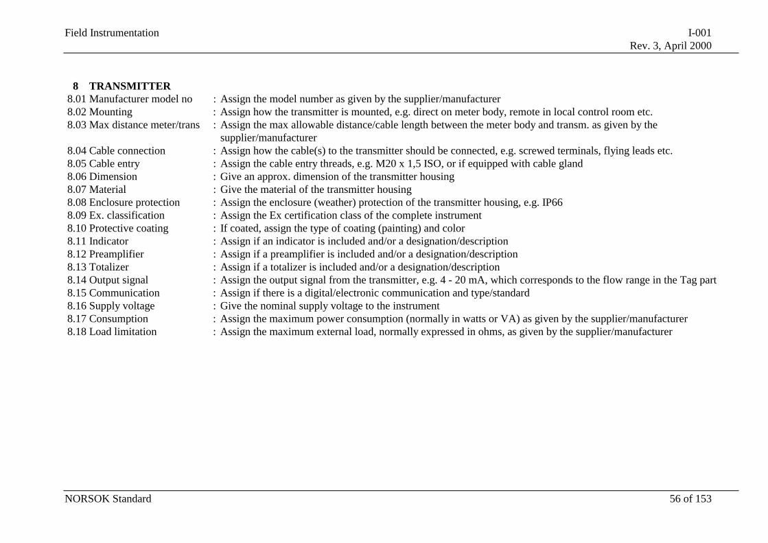
Field Instrumentation I-001Rev. 3, April 2000
NORSOK Standard 56 of 153
8 TRANSMITTER8.01 Manufacturer model no : Assign the model number as given by the supplier/manufacturer8.02 Mounting : Assign how the transmitter is mounted, e.g. direct on meter body, remote in local control room etc.8.03 Max distance meter/trans : Assign the max allowable distance/cable length between the meter body and transm. as given by the
supplier/manufacturer8.04 Cable connection : Assign how the cable(s) to the transmitter should be connected, e.g. screwed terminals, flying leads etc.8.05 Cable entry : Assign the cable entry threads, e.g. M20 x 1,5 ISO, or if equipped with cable gland8.06 Dimension : Give an approx. dimension of the transmitter housing8.07 Material : Give the material of the transmitter housing8.08 Enclosure protection : Assign the enclosure (weather) protection of the transmitter housing, e.g. IP668.09 Ex. classification : Assign the Ex certification class of the complete instrument8.10 Protective coating : If coated, assign the type of coating (painting) and color8.11 Indicator : Assign if an indicator is included and/or a designation/description8.12 Preamplifier : Assign if a preamplifier is included and/or a designation/description8.13 Totalizer : Assign if a totalizer is included and/or a designation/description8.14 Output signal : Assign the output signal from the transmitter, e.g. 4 - 20 mA, which corresponds to the flow range in the Tag part8.15 Communication : Assign if there is a digital/electronic communication and type/standard8.16 Supply voltage : Give the nominal supply voltage to the instrument8.17 Consumption : Assign the maximum power consumption (normally in watts or VA) as given by the supplier/manufacturer8.18 Load limitation : Assign the maximum external load, normally expressed in ohms, as given by the supplier/manufacturer
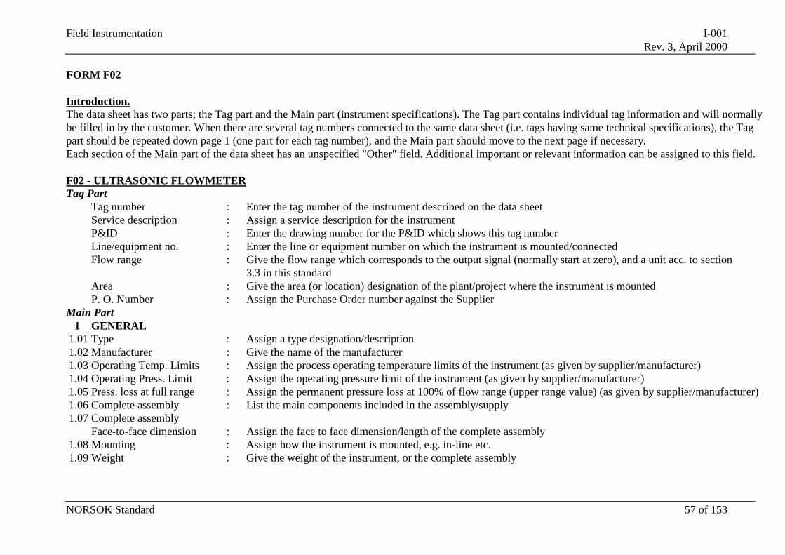
Field Instrumentation I-001Rev. 3, April 2000
NORSOK Standard 57 of 153
FORM F02
Introduction.The data sheet has two parts; the Tag part and the Main part (instrument specifications). The Tag part contains individual tag information and will normallybe filled in by the customer. When there are several tag numbers connected to the same data sheet (i.e. tags having same technical specifications), the Tagpart should be repeated down page 1 (one part for each tag number), and the Main part should move to the next page if necessary.Each section of the Main part of the data sheet has an unspecified "Other" field. Additional important or relevant information can be assigned to this field.
F02 - ULTRASONIC FLOWMETERTag Part
Tag number : Enter the tag number of the instrument described on the data sheetService description : Assign a service description for the instrumentP&ID : Enter the drawing number for the P&ID which shows this tag numberLine/equipment no. : Enter the line or equipment number on which the instrument is mounted/connectedFlow range : Give the flow range which corresponds to the output signal (normally start at zero), and a unit acc. to section
3.3 in this standardArea : Give the area (or location) designation of the plant/project where the instrument is mountedP. O. Number : Assign the Purchase Order number against the Supplier
Main Part1 GENERAL
1.01 Type : Assign a type designation/description1.02 Manufacturer : Give the name of the manufacturer1.03 Operating Temp. Limits : Assign the process operating temperature limits of the instrument (as given by supplier/manufacturer)1.04 Operating Press. Limit : Assign the operating pressure limit of the instrument (as given by supplier/manufacturer)1.05 Press. loss at full range : Assign the permanent pressure loss at 100% of flow range (upper range value) (as given by supplier/manufacturer)1.06 Complete assembly : List the main components included in the assembly/supply1.07 Complete assembly
Face-to-face dimension : Assign the face to face dimension/length of the complete assembly1.08 Mounting : Assign how the instrument is mounted, e.g. in-line etc.1.09 Weight : Give the weight of the instrument, or the complete assembly
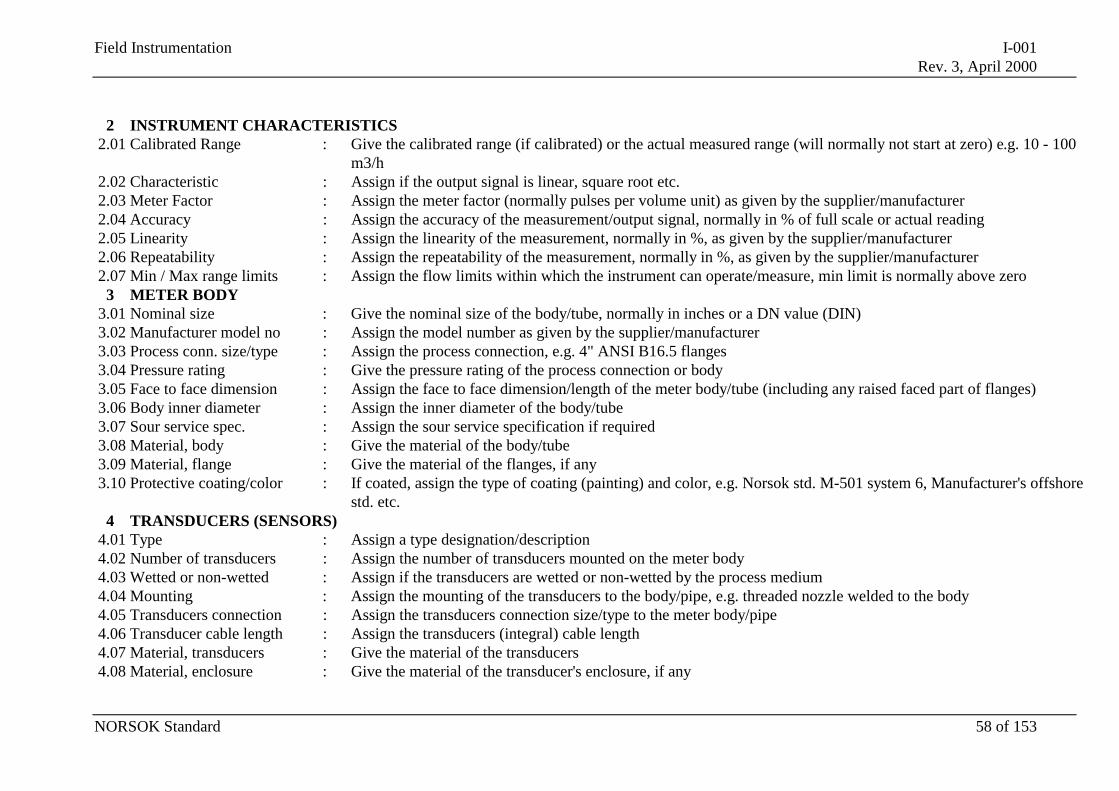
Field Instrumentation I-001Rev. 3, April 2000
NORSOK Standard 58 of 153
2 INSTRUMENT CHARACTERISTICS2.01 Calibrated Range : Give the calibrated range (if calibrated) or the actual measured range (will normally not start at zero) e.g. 10 - 100
m3/h2.02 Characteristic : Assign if the output signal is linear, square root etc.2.03 Meter Factor : Assign the meter factor (normally pulses per volume unit) as given by the supplier/manufacturer2.04 Accuracy : Assign the accuracy of the measurement/output signal, normally in % of full scale or actual reading2.05 Linearity : Assign the linearity of the measurement, normally in %, as given by the supplier/manufacturer2.06 Repeatability : Assign the repeatability of the measurement, normally in %, as given by the supplier/manufacturer2.07 Min / Max range limits : Assign the flow limits within which the instrument can operate/measure, min limit is normally above zero
3 METER BODY3.01 Nominal size : Give the nominal size of the body/tube, normally in inches or a DN value (DIN)3.02 Manufacturer model no : Assign the model number as given by the supplier/manufacturer3.03 Process conn. size/type : Assign the process connection, e.g. 4" ANSI B16.5 flanges3.04 Pressure rating : Give the pressure rating of the process connection or body3.05 Face to face dimension : Assign the face to face dimension/length of the meter body/tube (including any raised faced part of flanges)3.06 Body inner diameter : Assign the inner diameter of the body/tube3.07 Sour service spec. : Assign the sour service specification if required3.08 Material, body : Give the material of the body/tube3.09 Material, flange : Give the material of the flanges, if any3.10 Protective coating/color : If coated, assign the type of coating (painting) and color, e.g. Norsok std. M-501 system 6, Manufacturer's offshore
std. etc.4 TRANSDUCERS (SENSORS)
4.01 Type : Assign a type designation/description4.02 Number of transducers : Assign the number of transducers mounted on the meter body4.03 Wetted or non-wetted : Assign if the transducers are wetted or non-wetted by the process medium4.04 Mounting : Assign the mounting of the transducers to the body/pipe, e.g. threaded nozzle welded to the body4.05 Transducers connection : Assign the transducers connection size/type to the meter body/pipe4.06 Transducer cable length : Assign the transducers (integral) cable length4.07 Material, transducers : Give the material of the transducers4.08 Material, enclosure : Give the material of the transducer's enclosure, if any
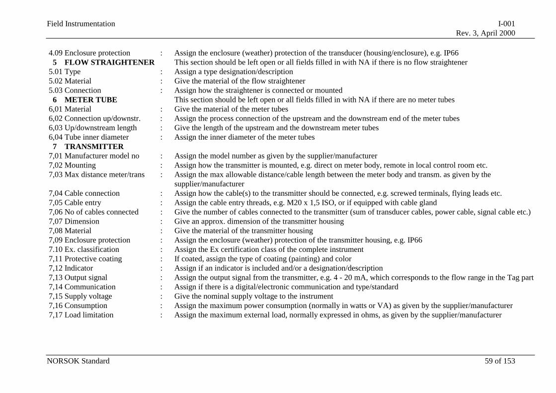
Field Instrumentation I-001Rev. 3, April 2000
NORSOK Standard 59 of 153
4.09 Enclosure protection : Assign the enclosure (weather) protection of the transducer (housing/enclosure), e.g. IP665 FLOW STRAIGHTENER This section should be left open or all fields filled in with NA if there is no flow straightener
5.01 Type : Assign a type designation/description5.02 Material : Give the material of the flow straightener5.03 Connection : Assign how the straightener is connected or mounted
6 METER TUBE This section should be left open or all fields filled in with NA if there are no meter tubes6,01 Material : Give the material of the meter tubes6,02 Connection up/downstr. : Assign the process connection of the upstream and the downstream end of the meter tubes6,03 Up/downstream length : Give the length of the upstream and the downstream meter tubes6,04 Tube inner diameter : Assign the inner diameter of the meter tubes
7 TRANSMITTER7,01 Manufacturer model no : Assign the model number as given by the supplier/manufacturer7,02 Mounting : Assign how the transmitter is mounted, e.g. direct on meter body, remote in local control room etc.7,03 Max distance meter/trans : Assign the max allowable distance/cable length between the meter body and transm. as given by the
supplier/manufacturer7,04 Cable connection : Assign how the cable(s) to the transmitter should be connected, e.g. screwed terminals, flying leads etc.7,05 Cable entry : Assign the cable entry threads, e.g. M20 x 1,5 ISO, or if equipped with cable gland7,06 No of cables connected : Give the number of cables connected to the transmitter (sum of transducer cables, power cable, signal cable etc.)7,07 Dimension : Give an approx. dimension of the transmitter housing7,08 Material : Give the material of the transmitter housing7,09 Enclosure protection : Assign the enclosure (weather) protection of the transmitter housing, e.g. IP667.10 Ex. classification : Assign the Ex certification class of the complete instrument7,11 Protective coating : If coated, assign the type of coating (painting) and color7,12 Indicator : Assign if an indicator is included and/or a designation/description7,13 Output signal : Assign the output signal from the transmitter, e.g. 4 - 20 mA, which corresponds to the flow range in the Tag part7,14 Communication : Assign if there is a digital/electronic communication and type/standard7,15 Supply voltage : Give the nominal supply voltage to the instrument7,16 Consumption : Assign the maximum power consumption (normally in watts or VA) as given by the supplier/manufacturer7,17 Load limitation : Assign the maximum external load, normally expressed in ohms, as given by the supplier/manufacturer
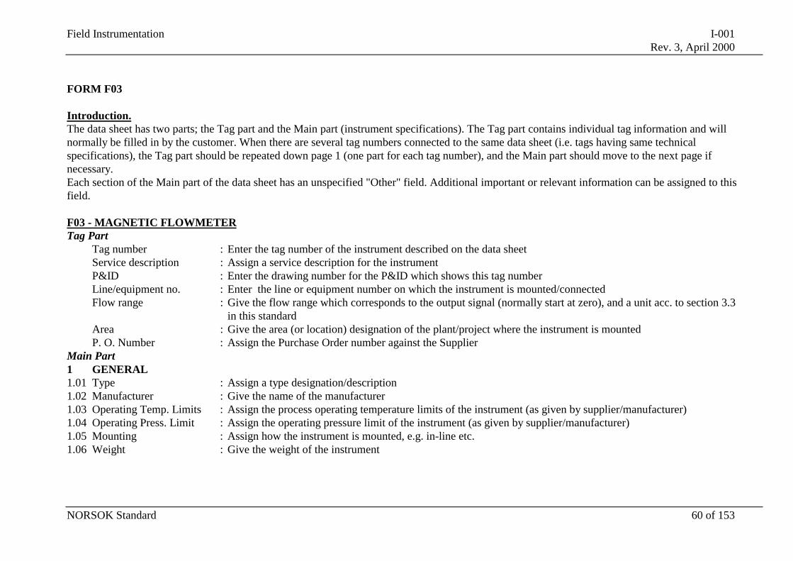
Field Instrumentation I-001Rev. 3, April 2000
NORSOK Standard 60 of 153
FORM F03
Introduction.The data sheet has two parts; the Tag part and the Main part (instrument specifications). The Tag part contains individual tag information and willnormally be filled in by the customer. When there are several tag numbers connected to the same data sheet (i.e. tags having same technicalspecifications), the Tag part should be repeated down page 1 (one part for each tag number), and the Main part should move to the next page ifnecessary.Each section of the Main part of the data sheet has an unspecified "Other" field. Additional important or relevant information can be assigned to thisfield.
F03 - MAGNETIC FLOWMETERTag Part
Tag number : Enter the tag number of the instrument described on the data sheetService description : Assign a service description for the instrumentP&ID : Enter the drawing number for the P&ID which shows this tag numberLine/equipment no. : Enter the line or equipment number on which the instrument is mounted/connectedFlow range : Give the flow range which corresponds to the output signal (normally start at zero), and a unit acc. to section 3.3
in this standardArea : Give the area (or location) designation of the plant/project where the instrument is mountedP. O. Number : Assign the Purchase Order number against the Supplier
Main Part1 GENERAL1.01 Type : Assign a type designation/description1.02 Manufacturer : Give the name of the manufacturer1.03 Operating Temp. Limits : Assign the process operating temperature limits of the instrument (as given by supplier/manufacturer)1.04 Operating Press. Limit : Assign the operating pressure limit of the instrument (as given by supplier/manufacturer)1.05 Mounting : Assign how the instrument is mounted, e.g. in-line etc.1.06 Weight : Give the weight of the instrument
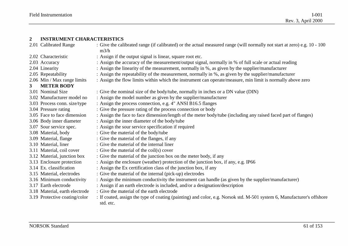
Field Instrumentation I-001Rev. 3, April 2000
NORSOK Standard 61 of 153
2 INSTRUMENT CHARACTERISTICS2.01 Calibrated Range : Give the calibrated range (if calibrated) or the actual measured range (will normally not start at zero) e.g. 10 - 100
m3/h2.02 Characteristic : Assign if the output signal is linear, square root etc.2.03 Accuracy : Assign the accuracy of the measurement/output signal, normally in % of full scale or actual reading2.04 Linearity : Assign the linearity of the measurement, normally in %, as given by the supplier/manufacturer2.05 Repeatability : Assign the repeatability of the measurement, normally in %, as given by the supplier/manufacturer2.06 Min / Max range limits : Assign the flow limits within which the instrument can operate/measure, min limit is normally above zero3 METER BODY3.01 Nominal Size : Give the nominal size of the body/tube, normally in inches or a DN value (DIN)3.02 Manufacturer model no : Assign the model number as given by the supplier/manufacturer3.03 Process conn. size/type : Assign the process connection, e.g. 4" ANSI B16.5 flanges3.04 Pressure rating : Give the pressure rating of the process connection or body3.05 Face to face dimension : Assign the face to face dimension/length of the meter body/tube (including any raised faced part of flanges)3.06 Body inner diameter : Assign the inner diameter of the body/tube3.07 Sour service spec. : Assign the sour service specification if required3.08 Material, body : Give the material of the body/tube3.09 Material, flange : Give the material of the flanges, if any3.10 Material, liner : Give the material of the internal liner3.11 Material, coil cover : Give the material of the coil(s) cover3.12 Material, junction box : Give the material of the junction box on the meter body, if any3.13 Enclosure protection : Assign the enclosure (weather) protection of the junction box, if any, e.g. IP663.14 Ex. classification : Assign the Ex certification class of the junction box, if any3.15 Material, electrodes : Give the material of the internal (pick-up) electrodes3.16 Minimum conductivity : Assign the minimum conductivity the instrument can handle (as given by the supplier/manufacturer)3.17 Earth electrode : Assign if an earth electrode is included, and/or a designation/description3.18 Material, earth electrode : Give the material of the earth electrode3.19 Protective coating/color : If coated, assign the type of coating (painting) and color, e.g. Norsok std. M-501 system 6, Manufacturer's offshore
std. etc.

Field Instrumentation I-001Rev. 3, April 2000
NORSOK Standard 62 of 153
4 TRANSMITTER4,01 Manufacturer model no : Assign the model number as given by the supplier/manufacturer4,02 Mounting : Assign how the transmitter is mounted, e.g. direct on meter body, remote in local control room etc.4,03 Max distance meter/trans : Assign the max allowable distance/cable length between the meter body and transm. as given by the
supplier/manufacturer4,04 Cable connection : Assign how the cable(s) to the transmitter should be connected, e.g. screwed terminals, flying leads etc.4,05 Cable entry : Assign the cable entry threads, e.g. M20 x 1,5 ISO, or if equipped with cable gland4,06 Dimension : Give an approx. dimension of the transmitter housing4,07 Material : Give the material of the transmitter housing4.08 Enclosure protection : Assign the enclosure (weather) protection of the transmitter housing, e.g. IP664.09 Ex. classification : Assign the Ex certification class of the complete instrument4.10 Protective coating : If coated, assign the type of coating (painting) and color4.11 Indicator : Assign if an indicator is included and/or a designation/description4.12 Output signal : Assign the output signal from the transmitter, e.g. 4 - 20 mA, which corresponds to the flow range in the Tag part4.13 Communication : Assign if there is a digital/electronic communication and type/standard4.14 Supply voltage : Give the nominal supply voltage to the instrument4.15 Consumption : Assign the maximum power consumption (normally in watts or VA) as given by the supplier/manufacturer4.16 Load limitation : Assign the maximum external load, normally expressed in ohms, as given by the supplier/manufacturer
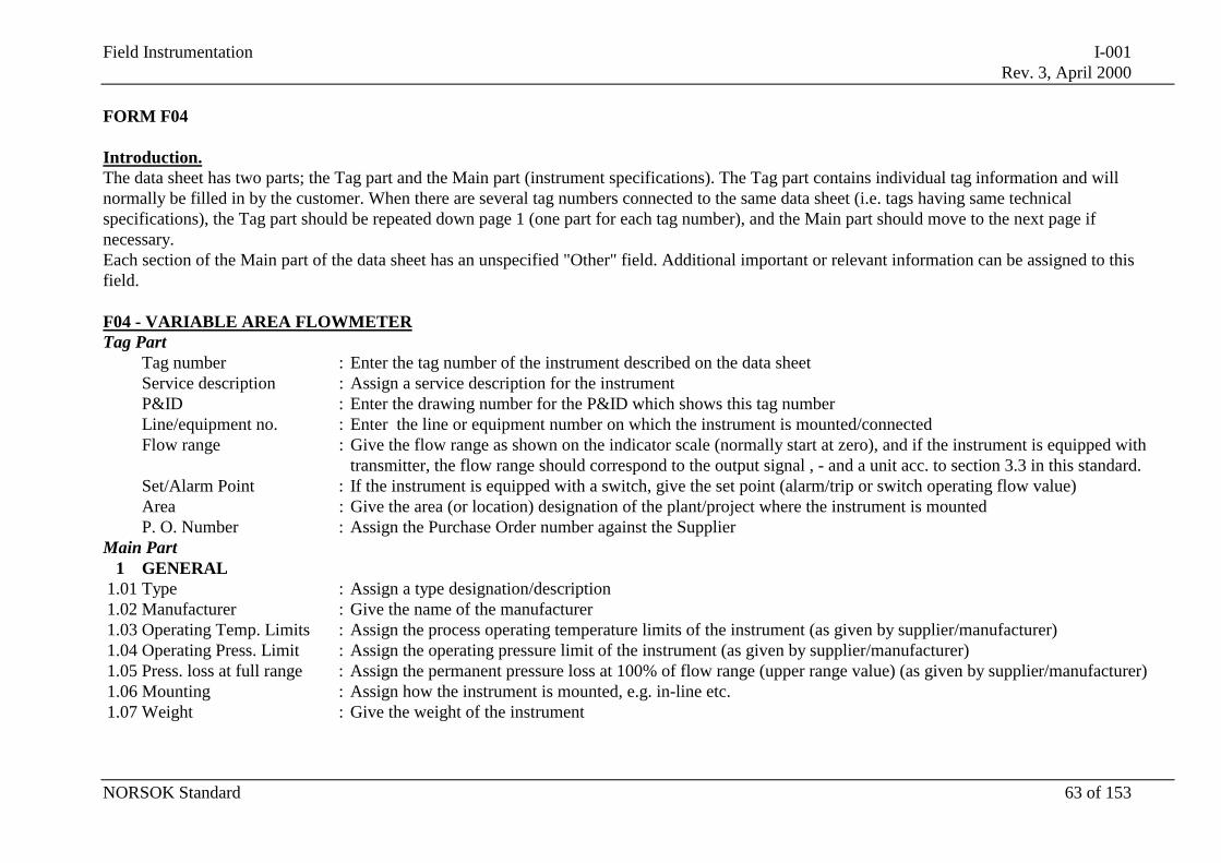
Field Instrumentation I-001Rev. 3, April 2000
NORSOK Standard 63 of 153
FORM F04
Introduction.The data sheet has two parts; the Tag part and the Main part (instrument specifications). The Tag part contains individual tag information and willnormally be filled in by the customer. When there are several tag numbers connected to the same data sheet (i.e. tags having same technicalspecifications), the Tag part should be repeated down page 1 (one part for each tag number), and the Main part should move to the next page ifnecessary.Each section of the Main part of the data sheet has an unspecified "Other" field. Additional important or relevant information can be assigned to thisfield.
F04 - VARIABLE AREA FLOWMETERTag Part
Tag number : Enter the tag number of the instrument described on the data sheetService description : Assign a service description for the instrumentP&ID : Enter the drawing number for the P&ID which shows this tag numberLine/equipment no. : Enter the line or equipment number on which the instrument is mounted/connectedFlow range : Give the flow range as shown on the indicator scale (normally start at zero), and if the instrument is equipped with
transmitter, the flow range should correspond to the output signal , - and a unit acc. to section 3.3 in this standard.Set/Alarm Point : If the instrument is equipped with a switch, give the set point (alarm/trip or switch operating flow value)Area : Give the area (or location) designation of the plant/project where the instrument is mountedP. O. Number : Assign the Purchase Order number against the Supplier
Main Part1 GENERAL
1.01 Type : Assign a type designation/description1.02 Manufacturer : Give the name of the manufacturer1.03 Operating Temp. Limits : Assign the process operating temperature limits of the instrument (as given by supplier/manufacturer)1.04 Operating Press. Limit : Assign the operating pressure limit of the instrument (as given by supplier/manufacturer)1.05 Press. loss at full range : Assign the permanent pressure loss at 100% of flow range (upper range value) (as given by supplier/manufacturer)1.06 Mounting : Assign how the instrument is mounted, e.g. in-line etc.1.07 Weight : Give the weight of the instrument
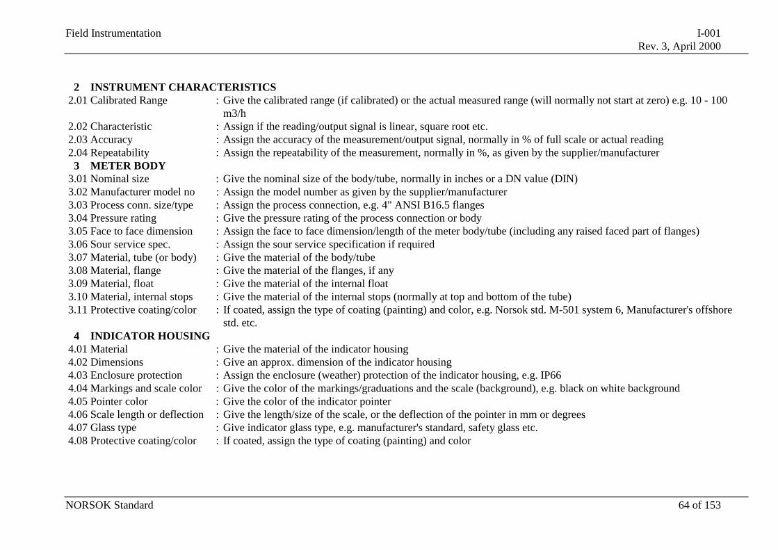
Field Instrumentation I-001Rev. 3, April 2000
NORSOK Standard 64 of 153
2 INSTRUMENT CHARACTERISTICS2.01 Calibrated Range : Give the calibrated range (if calibrated) or the actual measured range (will normally not start at zero) e.g. 10 - 100
m3/h2.02 Characteristic : Assign if the reading/output signal is linear, square root etc.2.03 Accuracy : Assign the accuracy of the measurement/output signal, normally in % of full scale or actual reading2.04 Repeatability : Assign the repeatability of the measurement, normally in %, as given by the supplier/manufacturer
3 METER BODY3.01 Nominal size : Give the nominal size of the body/tube, normally in inches or a DN value (DIN)3.02 Manufacturer model no : Assign the model number as given by the supplier/manufacturer3.03 Process conn. size/type : Assign the process connection, e.g. 4" ANSI B16.5 flanges3.04 Pressure rating : Give the pressure rating of the process connection or body3.05 Face to face dimension : Assign the face to face dimension/length of the meter body/tube (including any raised faced part of flanges)3.06 Sour service spec. : Assign the sour service specification if required3.07 Material, tube (or body) : Give the material of the body/tube3.08 Material, flange : Give the material of the flanges, if any3.09 Material, float : Give the material of the internal float3.10 Material, internal stops : Give the material of the internal stops (normally at top and bottom of the tube)3.11 Protective coating/color : If coated, assign the type of coating (painting) and color, e.g. Norsok std. M-501 system 6, Manufacturer's offshore
std. etc.4 INDICATOR HOUSING
4.01 Material : Give the material of the indicator housing4.02 Dimensions : Give an approx. dimension of the indicator housing4.03 Enclosure protection : Assign the enclosure (weather) protection of the indicator housing, e.g. IP664.04 Markings and scale color : Give the color of the markings/graduations and the scale (background), e.g. black on white background4.05 Pointer color : Give the color of the indicator pointer4.06 Scale length or deflection : Give the length/size of the scale, or the deflection of the pointer in mm or degrees4.07 Glass type : Give indicator glass type, e.g. manufacturer's standard, safety glass etc.4.08 Protective coating/color : If coated, assign the type of coating (painting) and color
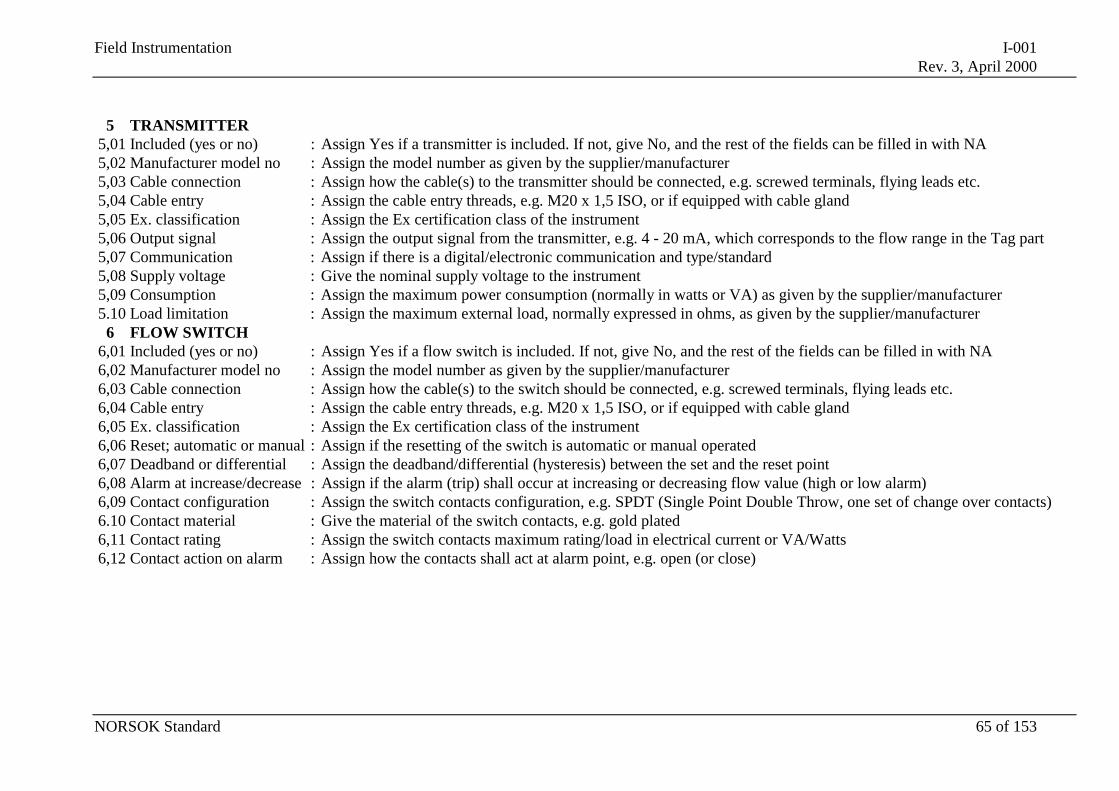
Field Instrumentation I-001Rev. 3, April 2000
NORSOK Standard 65 of 153
5 TRANSMITTER5,01 Included (yes or no) : Assign Yes if a transmitter is included. If not, give No, and the rest of the fields can be filled in with NA5,02 Manufacturer model no : Assign the model number as given by the supplier/manufacturer5,03 Cable connection : Assign how the cable(s) to the transmitter should be connected, e.g. screwed terminals, flying leads etc.5,04 Cable entry : Assign the cable entry threads, e.g. M20 x 1,5 ISO, or if equipped with cable gland5,05 Ex. classification : Assign the Ex certification class of the instrument5,06 Output signal : Assign the output signal from the transmitter, e.g. 4 - 20 mA, which corresponds to the flow range in the Tag part5,07 Communication : Assign if there is a digital/electronic communication and type/standard5,08 Supply voltage : Give the nominal supply voltage to the instrument5,09 Consumption : Assign the maximum power consumption (normally in watts or VA) as given by the supplier/manufacturer5.10 Load limitation : Assign the maximum external load, normally expressed in ohms, as given by the supplier/manufacturer
6 FLOW SWITCH6,01 Included (yes or no) : Assign Yes if a flow switch is included. If not, give No, and the rest of the fields can be filled in with NA6,02 Manufacturer model no : Assign the model number as given by the supplier/manufacturer6,03 Cable connection : Assign how the cable(s) to the switch should be connected, e.g. screwed terminals, flying leads etc.6,04 Cable entry : Assign the cable entry threads, e.g. M20 x 1,5 ISO, or if equipped with cable gland6,05 Ex. classification : Assign the Ex certification class of the instrument6,06 Reset; automatic or manual : Assign if the resetting of the switch is automatic or manual operated6,07 Deadband or differential : Assign the deadband/differential (hysteresis) between the set and the reset point6,08 Alarm at increase/decrease : Assign if the alarm (trip) shall occur at increasing or decreasing flow value (high or low alarm)6,09 Contact configuration : Assign the switch contacts configuration, e.g. SPDT (Single Point Double Throw, one set of change over contacts)6.10 Contact material : Give the material of the switch contacts, e.g. gold plated6,11 Contact rating : Assign the switch contacts maximum rating/load in electrical current or VA/Watts6,12 Contact action on alarm : Assign how the contacts shall act at alarm point, e.g. open (or close)
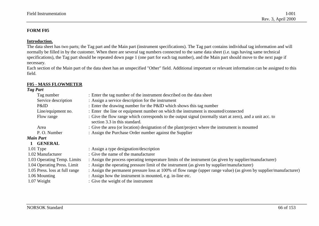
Field Instrumentation I-001Rev. 3, April 2000
NORSOK Standard 66 of 153
FORM F05
Introduction.The data sheet has two parts; the Tag part and the Main part (instrument specifications). The Tag part contains individual tag information and willnormally be filled in by the customer. When there are several tag numbers connected to the same data sheet (i.e. tags having same technicalspecifications), the Tag part should be repeated down page 1 (one part for each tag number), and the Main part should move to the next page ifnecessary.Each section of the Main part of the data sheet has an unspecified "Other" field. Additional important or relevant information can be assigned to thisfield.
F05 - MASS FLOWMETERTag Part
Tag number : Enter the tag number of the instrument described on the data sheetService description : Assign a service description for the instrumentP&ID : Enter the drawing number for the P&ID which shows this tag numberLine/equipment no. : Enter the line or equipment number on which the instrument is mounted/connectedFlow range : Give the flow range which corresponds to the output signal (normally start at zero), and a unit acc. to
section 3.3 in this standard.Area : Give the area (or location) designation of the plant/project where the instrument is mountedP. O. Number : Assign the Purchase Order number against the Supplier
Main Part1 GENERAL
1.01 Type : Assign a type designation/description1.02 Manufacturer : Give the name of the manufacturer1.03 Operating Temp. Limits : Assign the process operating temperature limits of the instrument (as given by supplier/manufacturer)1.04 Operating Press. Limit : Assign the operating pressure limit of the instrument (as given by supplier/manufacturer)1.05 Press. loss at full range : Assign the permanent pressure loss at 100% of flow range (upper range value) (as given by supplier/manufacturer)1.06 Mounting : Assign how the instrument is mounted, e.g. in-line etc.1.07 Weight : Give the weight of the instrument
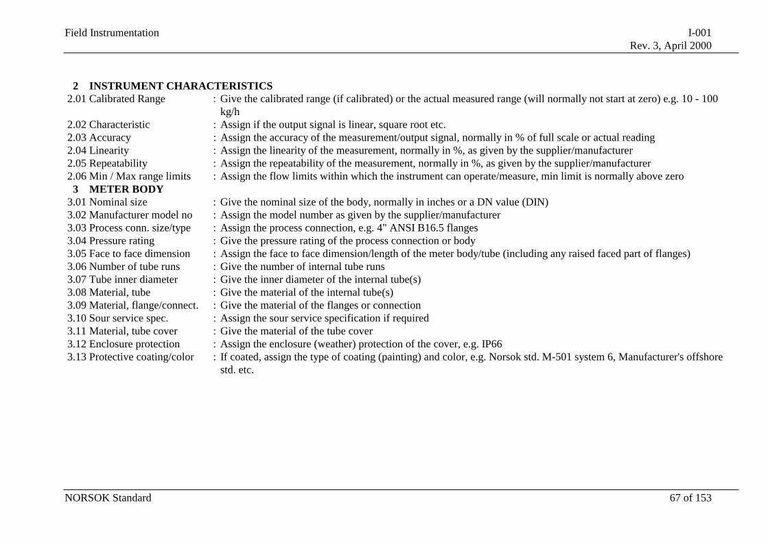
Field Instrumentation I-001Rev. 3, April 2000
NORSOK Standard 67 of 153
2 INSTRUMENT CHARACTERISTICS2.01 Calibrated Range : Give the calibrated range (if calibrated) or the actual measured range (will normally not start at zero) e.g. 10 - 100
kg/h2.02 Characteristic : Assign if the output signal is linear, square root etc.2.03 Accuracy : Assign the accuracy of the measurement/output signal, normally in % of full scale or actual reading2.04 Linearity : Assign the linearity of the measurement, normally in %, as given by the supplier/manufacturer2.05 Repeatability : Assign the repeatability of the measurement, normally in %, as given by the supplier/manufacturer2.06 Min / Max range limits : Assign the flow limits within which the instrument can operate/measure, min limit is normally above zero
3 METER BODY3.01 Nominal size : Give the nominal size of the body, normally in inches or a DN value (DIN)3.02 Manufacturer model no : Assign the model number as given by the supplier/manufacturer3.03 Process conn. size/type : Assign the process connection, e.g. 4" ANSI B16.5 flanges3.04 Pressure rating : Give the pressure rating of the process connection or body3.05 Face to face dimension : Assign the face to face dimension/length of the meter body/tube (including any raised faced part of flanges)3.06 Number of tube runs : Give the number of internal tube runs3.07 Tube inner diameter : Give the inner diameter of the internal tube(s)3.08 Material, tube : Give the material of the internal tube(s)3.09 Material, flange/connect. : Give the material of the flanges or connection3.10 Sour service spec. : Assign the sour service specification if required3.11 Material, tube cover : Give the material of the tube cover3.12 Enclosure protection : Assign the enclosure (weather) protection of the cover, e.g. IP663.13 Protective coating/color : If coated, assign the type of coating (painting) and color, e.g. Norsok std. M-501 system 6, Manufacturer's offshore
std. etc.
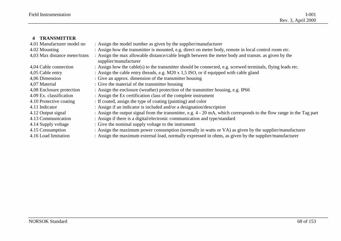
Field Instrumentation I-001Rev. 3, April 2000
NORSOK Standard 68 of 153
4 TRANSMITTER4.01 Manufacturer model no : Assign the model number as given by the supplier/manufacturer4.02 Mounting : Assign how the transmitter is mounted, e.g. direct on meter body, remote in local control room etc.4,03 Max distance meter/trans : Assign the max allowable distance/cable length between the meter body and transm. as given by the
supplier/manufacturer4,04 Cable connection : Assign how the cable(s) to the transmitter should be connected, e.g. screwed terminals, flying leads etc.4,05 Cable entry : Assign the cable entry threads, e.g. M20 x 1,5 ISO, or if equipped with cable gland4,06 Dimension : Give an approx. dimension of the transmitter housing4,07 Material : Give the material of the transmitter housing4,08 Enclosure protection : Assign the enclosure (weather) protection of the transmitter housing, e.g. IP664.09 Ex. classification : Assign the Ex certification class of the complete instrument4.10 Protective coating : If coated, assign the type of coating (painting) and color4.11 Indicator : Assign if an indicator is included and/or a designation/description4.12 Output signal : Assign the output signal from the transmitter, e.g. 4 - 20 mA, which corresponds to the flow range in the Tag part4.13 Communication : Assign if there is a digital/electronic communication and type/standard4.14 Supply voltage : Give the nominal supply voltage to the instrument4.15 Consumption : Assign the maximum power consumption (normally in watts or VA) as given by the supplier/manufacturer4.16 Load limitation : Assign the maximum external load, normally expressed in ohms, as given by the supplier/manufacturer
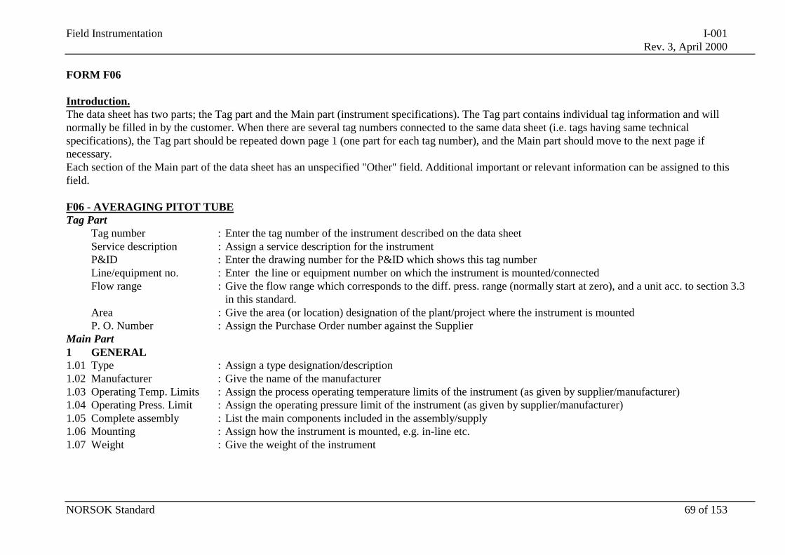
Field Instrumentation I-001Rev. 3, April 2000
NORSOK Standard 69 of 153
FORM F06
Introduction.The data sheet has two parts; the Tag part and the Main part (instrument specifications). The Tag part contains individual tag information and willnormally be filled in by the customer. When there are several tag numbers connected to the same data sheet (i.e. tags having same technicalspecifications), the Tag part should be repeated down page 1 (one part for each tag number), and the Main part should move to the next page ifnecessary.Each section of the Main part of the data sheet has an unspecified "Other" field. Additional important or relevant information can be assigned to thisfield.
F06 - AVERAGING PITOT TUBETag Part
Tag number : Enter the tag number of the instrument described on the data sheetService description : Assign a service description for the instrumentP&ID : Enter the drawing number for the P&ID which shows this tag numberLine/equipment no. : Enter the line or equipment number on which the instrument is mounted/connectedFlow range : Give the flow range which corresponds to the diff. press. range (normally start at zero), and a unit acc. to section 3.3
in this standard.Area : Give the area (or location) designation of the plant/project where the instrument is mountedP. O. Number : Assign the Purchase Order number against the Supplier
Main Part1 GENERAL1.01 Type : Assign a type designation/description1.02 Manufacturer : Give the name of the manufacturer1.03 Operating Temp. Limits : Assign the process operating temperature limits of the instrument (as given by supplier/manufacturer)1.04 Operating Press. Limit : Assign the operating pressure limit of the instrument (as given by supplier/manufacturer)1.05 Complete assembly : List the main components included in the assembly/supply1.06 Mounting : Assign how the instrument is mounted, e.g. in-line etc.1.07 Weight : Give the weight of the instrument
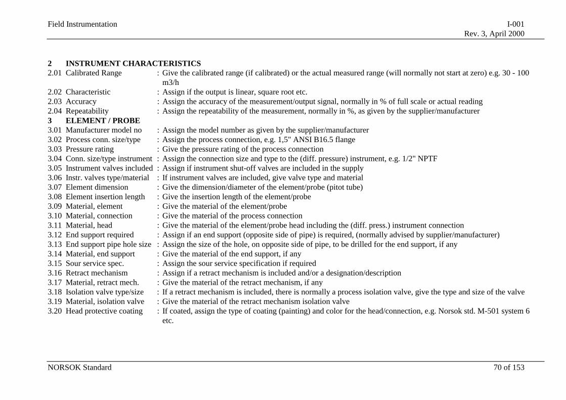
Field Instrumentation I-001Rev. 3, April 2000
NORSOK Standard 70 of 153
2 INSTRUMENT CHARACTERISTICS2.01 Calibrated Range : Give the calibrated range (if calibrated) or the actual measured range (will normally not start at zero) e.g. 30 - 100
m3/h2.02 Characteristic : Assign if the output is linear, square root etc.2.03 Accuracy : Assign the accuracy of the measurement/output signal, normally in % of full scale or actual reading2.04 Repeatability : Assign the repeatability of the measurement, normally in %, as given by the supplier/manufacturer3 ELEMENT / PROBE3.01 Manufacturer model no : Assign the model number as given by the supplier/manufacturer3.02 Process conn. size/type : Assign the process connection, e.g. 1,5" ANSI B16.5 flange3.03 Pressure rating : Give the pressure rating of the process connection3.04 Conn. size/type instrument : Assign the connection size and type to the (diff. pressure) instrument, e.g. 1/2" NPTF3.05 Instrument valves included : Assign if instrument shut-off valves are included in the supply3.06 Instr. valves type/material : If instrument valves are included, give valve type and material3.07 Element dimension : Give the dimension/diameter of the element/probe (pitot tube)3.08 Element insertion length : Give the insertion length of the element/probe3.09 Material, element : Give the material of the element/probe3.10 Material, connection : Give the material of the process connection3.11 Material, head : Give the material of the element/probe head including the (diff. press.) instrument connection3.12 End support required : Assign if an end support (opposite side of pipe) is required, (normally advised by supplier/manufacturer)3.13 End support pipe hole size : Assign the size of the hole, on opposite side of pipe, to be drilled for the end support, if any3.14 Material, end support : Give the material of the end support, if any3.15 Sour service spec. : Assign the sour service specification if required3.16 Retract mechanism : Assign if a retract mechanism is included and/or a designation/description3.17 Material, retract mech. : Give the material of the retract mechanism, if any3.18 Isolation valve type/size : If a retract mechanism is included, there is normally a process isolation valve, give the type and size of the valve3.19 Material, isolation valve : Give the material of the retract mechanism isolation valve3.20 Head protective coating : If coated, assign the type of coating (painting) and color for the head/connection, e.g. Norsok std. M-501 system 6
etc.
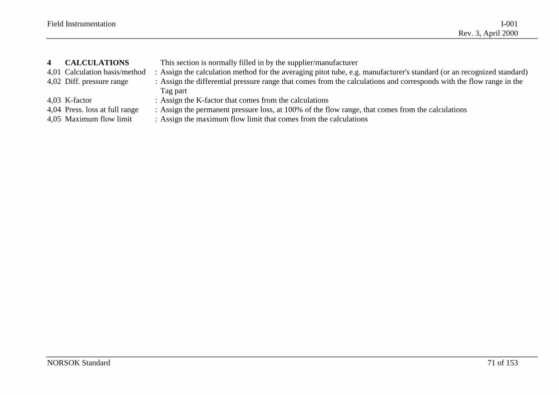
Field Instrumentation I-001Rev. 3, April 2000
NORSOK Standard 71 of 153
4 CALCULATIONS This section is normally filled in by the supplier/manufacturer4,01 Calculation basis/method : Assign the calculation method for the averaging pitot tube, e.g. manufacturer's standard (or an recognized standard)4,02 Diff. pressure range : Assign the differential pressure range that comes from the calculations and corresponds with the flow range in the
Tag part4,03 K-factor : Assign the K-factor that comes from the calculations4,04 Press. loss at full range : Assign the permanent pressure loss, at 100% of the flow range, that comes from the calculations4,05 Maximum flow limit : Assign the maximum flow limit that comes from the calculations
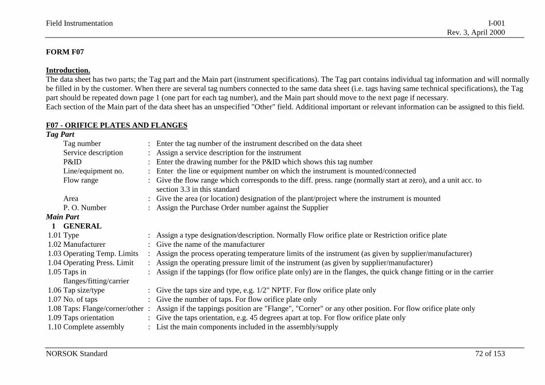
Field Instrumentation I-001Rev. 3, April 2000
NORSOK Standard 72 of 153
FORM F07
Introduction.The data sheet has two parts; the Tag part and the Main part (instrument specifications). The Tag part contains individual tag information and will normallybe filled in by the customer. When there are several tag numbers connected to the same data sheet (i.e. tags having same technical specifications), the Tagpart should be repeated down page 1 (one part for each tag number), and the Main part should move to the next page if necessary.Each section of the Main part of the data sheet has an unspecified "Other" field. Additional important or relevant information can be assigned to this field.
F07 - ORIFICE PLATES AND FLANGESTag Part
Tag number : Enter the tag number of the instrument described on the data sheetService description : Assign a service description for the instrumentP&ID : Enter the drawing number for the P&ID which shows this tag numberLine/equipment no. : Enter the line or equipment number on which the instrument is mounted/connectedFlow range : Give the flow range which corresponds to the diff. press. range (normally start at zero), and a unit acc. to
section 3.3 in this standardArea : Give the area (or location) designation of the plant/project where the instrument is mountedP. O. Number : Assign the Purchase Order number against the Supplier
Main Part1 GENERAL
1.01 Type : Assign a type designation/description. Normally Flow orifice plate or Restriction orifice plate1.02 Manufacturer : Give the name of the manufacturer1.03 Operating Temp. Limits : Assign the process operating temperature limits of the instrument (as given by supplier/manufacturer)1.04 Operating Press. Limit : Assign the operating pressure limit of the instrument (as given by supplier/manufacturer)1.05 Taps in
flanges/fitting/carrier: Assign if the tappings (for flow orifice plate only) are in the flanges, the quick change fitting or in the carrier
1.06 Tap size/type : Give the taps size and type, e.g. 1/2" NPTF. For flow orifice plate only1.07 No. of taps : Give the number of taps. For flow orifice plate only1.08 Taps: Flange/corner/other : Assign if the tappings position are "Flange", "Corner" or any other position. For flow orifice plate only1.09 Taps orientation : Give the taps orientation, e.g. 45 degrees apart at top. For flow orifice plate only1.10 Complete assembly : List the main components included in the assembly/supply
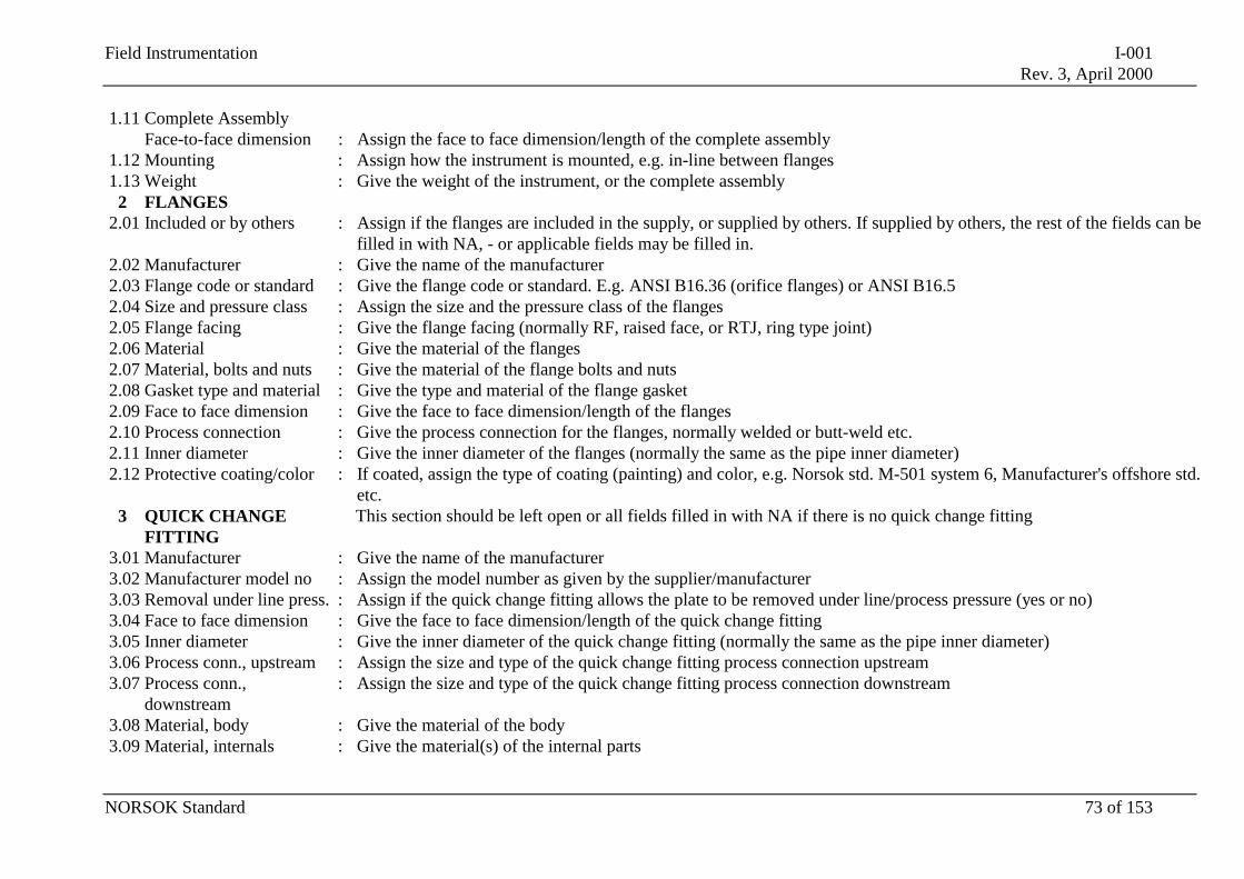
Field Instrumentation I-001Rev. 3, April 2000
NORSOK Standard 73 of 153
1.11 Complete AssemblyFace-to-face dimension : Assign the face to face dimension/length of the complete assembly
1.12 Mounting : Assign how the instrument is mounted, e.g. in-line between flanges1.13 Weight : Give the weight of the instrument, or the complete assembly
2 FLANGES2.01 Included or by others : Assign if the flanges are included in the supply, or supplied by others. If supplied by others, the rest of the fields can be
filled in with NA, - or applicable fields may be filled in.2.02 Manufacturer : Give the name of the manufacturer2.03 Flange code or standard : Give the flange code or standard. E.g. ANSI B16.36 (orifice flanges) or ANSI B16.52.04 Size and pressure class : Assign the size and the pressure class of the flanges2.05 Flange facing : Give the flange facing (normally RF, raised face, or RTJ, ring type joint)2.06 Material : Give the material of the flanges2.07 Material, bolts and nuts : Give the material of the flange bolts and nuts2.08 Gasket type and material : Give the type and material of the flange gasket2.09 Face to face dimension : Give the face to face dimension/length of the flanges2.10 Process connection : Give the process connection for the flanges, normally welded or butt-weld etc.2.11 Inner diameter : Give the inner diameter of the flanges (normally the same as the pipe inner diameter)2.12 Protective coating/color : If coated, assign the type of coating (painting) and color, e.g. Norsok std. M-501 system 6, Manufacturer's offshore std.
etc.3 QUICK CHANGE
FITTINGThis section should be left open or all fields filled in with NA if there is no quick change fitting
3.01 Manufacturer : Give the name of the manufacturer3.02 Manufacturer model no : Assign the model number as given by the supplier/manufacturer3.03 Removal under line press. : Assign if the quick change fitting allows the plate to be removed under line/process pressure (yes or no)3.04 Face to face dimension : Give the face to face dimension/length of the quick change fitting3.05 Inner diameter : Give the inner diameter of the quick change fitting (normally the same as the pipe inner diameter)3.06 Process conn., upstream : Assign the size and type of the quick change fitting process connection upstream3.07 Process conn.,
downstream: Assign the size and type of the quick change fitting process connection downstream
3.08 Material, body : Give the material of the body3.09 Material, internals : Give the material(s) of the internal parts
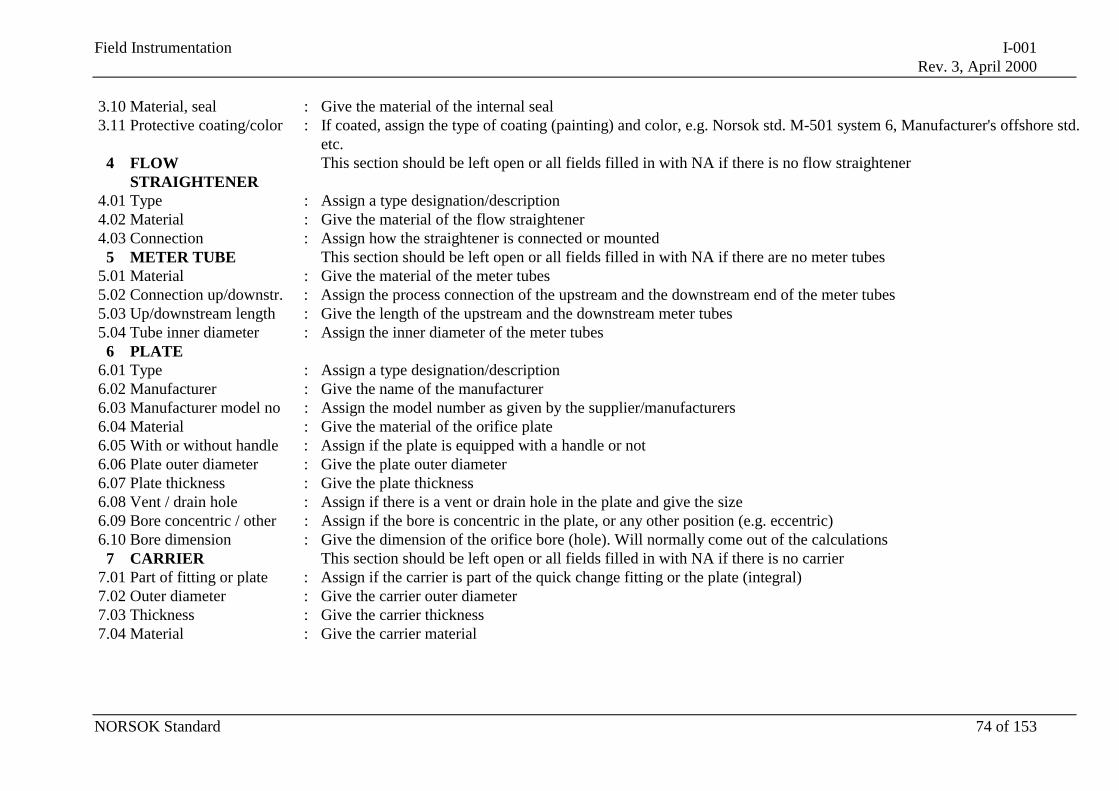
Field Instrumentation I-001Rev. 3, April 2000
NORSOK Standard 74 of 153
3.10 Material, seal : Give the material of the internal seal3.11 Protective coating/color : If coated, assign the type of coating (painting) and color, e.g. Norsok std. M-501 system 6, Manufacturer's offshore std.
etc.4 FLOW
STRAIGHTENERThis section should be left open or all fields filled in with NA if there is no flow straightener
4.01 Type : Assign a type designation/description4.02 Material : Give the material of the flow straightener4.03 Connection : Assign how the straightener is connected or mounted
5 METER TUBE This section should be left open or all fields filled in with NA if there are no meter tubes5.01 Material : Give the material of the meter tubes5.02 Connection up/downstr. : Assign the process connection of the upstream and the downstream end of the meter tubes5.03 Up/downstream length : Give the length of the upstream and the downstream meter tubes5.04 Tube inner diameter : Assign the inner diameter of the meter tubes
6 PLATE6.01 Type : Assign a type designation/description6.02 Manufacturer : Give the name of the manufacturer6.03 Manufacturer model no : Assign the model number as given by the supplier/manufacturers6.04 Material : Give the material of the orifice plate6.05 With or without handle : Assign if the plate is equipped with a handle or not6.06 Plate outer diameter : Give the plate outer diameter6.07 Plate thickness : Give the plate thickness6.08 Vent / drain hole : Assign if there is a vent or drain hole in the plate and give the size6.09 Bore concentric / other : Assign if the bore is concentric in the plate, or any other position (e.g. eccentric)6.10 Bore dimension : Give the dimension of the orifice bore (hole). Will normally come out of the calculations
7 CARRIER This section should be left open or all fields filled in with NA if there is no carrier7.01 Part of fitting or plate : Assign if the carrier is part of the quick change fitting or the plate (integral)7.02 Outer diameter : Give the carrier outer diameter7.03 Thickness : Give the carrier thickness7.04 Material : Give the carrier material
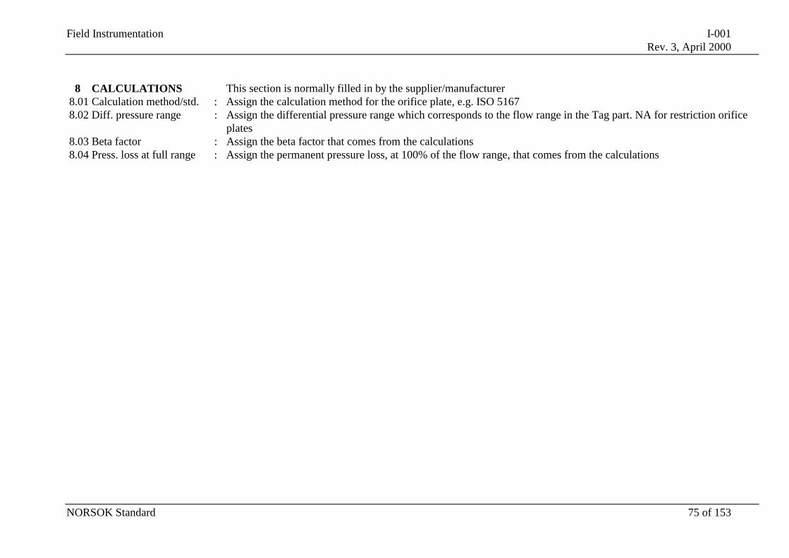
Field Instrumentation I-001Rev. 3, April 2000
NORSOK Standard 75 of 153
8 CALCULATIONS This section is normally filled in by the supplier/manufacturer8.01 Calculation method/std. : Assign the calculation method for the orifice plate, e.g. ISO 51678.02 Diff. pressure range : Assign the differential pressure range which corresponds to the flow range in the Tag part. NA for restriction orifice
plates8.03 Beta factor : Assign the beta factor that comes from the calculations8.04 Press. loss at full range : Assign the permanent pressure loss, at 100% of the flow range, that comes from the calculations
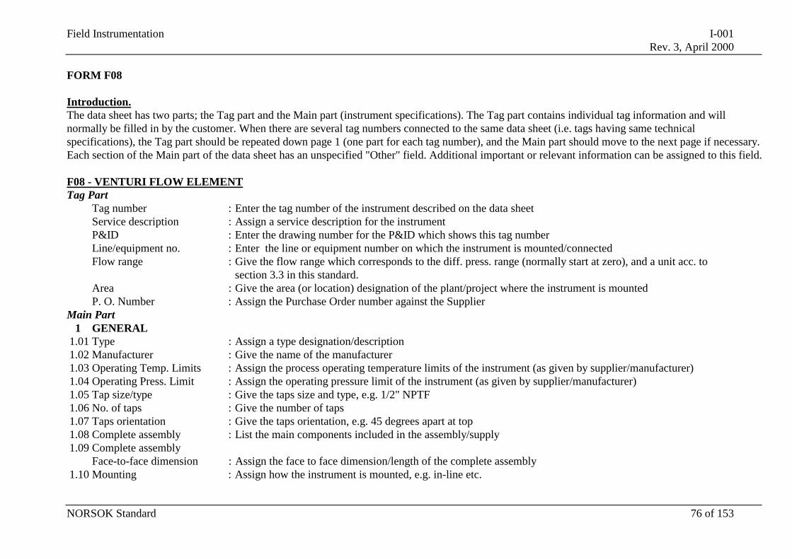
Field Instrumentation I-001Rev. 3, April 2000
NORSOK Standard 76 of 153
FORM F08
Introduction.The data sheet has two parts; the Tag part and the Main part (instrument specifications). The Tag part contains individual tag information and willnormally be filled in by the customer. When there are several tag numbers connected to the same data sheet (i.e. tags having same technicalspecifications), the Tag part should be repeated down page 1 (one part for each tag number), and the Main part should move to the next page if necessary.Each section of the Main part of the data sheet has an unspecified "Other" field. Additional important or relevant information can be assigned to this field.
F08 - VENTURI FLOW ELEMENTTag Part
Tag number : Enter the tag number of the instrument described on the data sheetService description : Assign a service description for the instrumentP&ID : Enter the drawing number for the P&ID which shows this tag numberLine/equipment no. : Enter the line or equipment number on which the instrument is mounted/connectedFlow range : Give the flow range which corresponds to the diff. press. range (normally start at zero), and a unit acc. to
section 3.3 in this standard.Area : Give the area (or location) designation of the plant/project where the instrument is mountedP. O. Number : Assign the Purchase Order number against the Supplier
Main Part1 GENERAL
1.01 Type : Assign a type designation/description1.02 Manufacturer : Give the name of the manufacturer1.03 Operating Temp. Limits : Assign the process operating temperature limits of the instrument (as given by supplier/manufacturer)1.04 Operating Press. Limit : Assign the operating pressure limit of the instrument (as given by supplier/manufacturer)1.05 Tap size/type : Give the taps size and type, e.g. 1/2" NPTF1.06 No. of taps : Give the number of taps1.07 Taps orientation : Give the taps orientation, e.g. 45 degrees apart at top1.08 Complete assembly : List the main components included in the assembly/supply1.09 Complete assembly
Face-to-face dimension : Assign the face to face dimension/length of the complete assembly1.10 Mounting : Assign how the instrument is mounted, e.g. in-line etc.
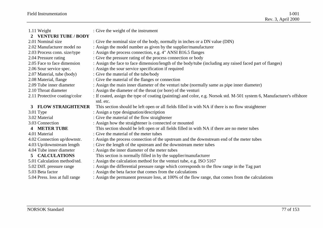
Field Instrumentation I-001Rev. 3, April 2000
NORSOK Standard 77 of 153
1.11 Weight : Give the weight of the instrument2 VENTURI TUBE / BODY
2.01 Nominal size : Give the nominal size of the body, normally in inches or a DN value (DIN)2.02 Manufacturer model no : Assign the model number as given by the supplier/manufacturer2.03 Process conn. size/type : Assign the process connection, e.g. 4" ANSI B16.5 flanges2.04 Pressure rating : Give the pressure rating of the process connection or body2.05 Face to face dimension : Assign the face to face dimension/length of the body/tube (including any raised faced part of flanges)2.06 Sour service spec. : Assign the sour service specification if required2.07 Material, tube (body) : Give the material of the tube/body2.08 Material, flange : Give the material of the flanges or connection2.09 Tube inner diameter : Assign the main inner diameter of the venturi tube (normally same as pipe inner diameter)2.10 Throat diameter : Assign the diameter of the throat (or bore) of the venturi2.11 Protective coating/color : If coated, assign the type of coating (painting) and color, e.g. Norsok std. M-501 system 6, Manufacturer's offshore
std. etc.3 FLOW STRAIGHTENER This section should be left open or all fields filled in with NA if there is no flow straightener
3.01 Type : Assign a type designation/description3.02 Material : Give the material of the flow straightener3.03 Connection : Assign how the straightener is connected or mounted
4 METER TUBE This section should be left open or all fields filled in with NA if there are no meter tubes4.01 Material : Give the material of the meter tubes4.02 Connection up/downstr. : Assign the process connection of the upstream and the downstream end of the meter tubes4.03 Up/downstream length : Give the length of the upstream and the downstream meter tubes4.04 Tube inner diameter : Assign the inner diameter of the meter tubes
5 CALCULATIONS This section is normally filled in by the supplier/manufacturer5.01 Calculation method/std. : Assign the calculation method for the venturi tube, e.g. ISO 51675.02 Diff. pressure range : Assign the differential pressure range which corresponds to the flow range in the Tag part5.03 Beta factor : Assign the beta factor that comes from the calculations5.04 Press. loss at full range : Assign the permanent pressure loss, at 100% of the flow range, that comes from the calculations
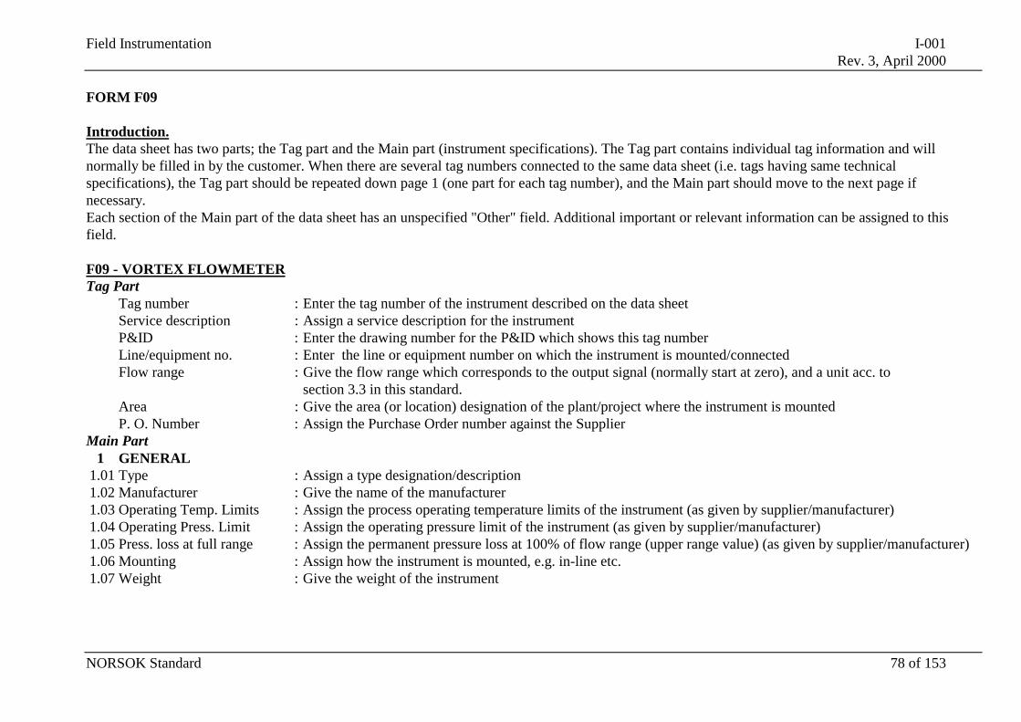
Field Instrumentation I-001Rev. 3, April 2000
NORSOK Standard 78 of 153
FORM F09
Introduction.The data sheet has two parts; the Tag part and the Main part (instrument specifications). The Tag part contains individual tag information and willnormally be filled in by the customer. When there are several tag numbers connected to the same data sheet (i.e. tags having same technicalspecifications), the Tag part should be repeated down page 1 (one part for each tag number), and the Main part should move to the next page ifnecessary.Each section of the Main part of the data sheet has an unspecified "Other" field. Additional important or relevant information can be assigned to thisfield.
F09 - VORTEX FLOWMETERTag Part
Tag number : Enter the tag number of the instrument described on the data sheetService description : Assign a service description for the instrumentP&ID : Enter the drawing number for the P&ID which shows this tag numberLine/equipment no. : Enter the line or equipment number on which the instrument is mounted/connectedFlow range : Give the flow range which corresponds to the output signal (normally start at zero), and a unit acc. to
section 3.3 in this standard.Area : Give the area (or location) designation of the plant/project where the instrument is mountedP. O. Number : Assign the Purchase Order number against the Supplier
Main Part1 GENERAL
1.01 Type : Assign a type designation/description1.02 Manufacturer : Give the name of the manufacturer1.03 Operating Temp. Limits : Assign the process operating temperature limits of the instrument (as given by supplier/manufacturer)1.04 Operating Press. Limit : Assign the operating pressure limit of the instrument (as given by supplier/manufacturer)1.05 Press. loss at full range : Assign the permanent pressure loss at 100% of flow range (upper range value) (as given by supplier/manufacturer)1.06 Mounting : Assign how the instrument is mounted, e.g. in-line etc.1.07 Weight : Give the weight of the instrument
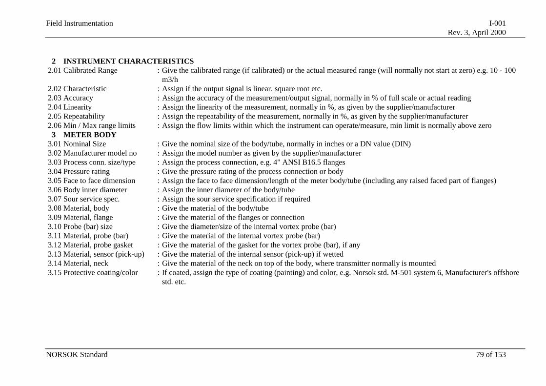
Field Instrumentation I-001Rev. 3, April 2000
NORSOK Standard 79 of 153
2 INSTRUMENT CHARACTERISTICS2.01 Calibrated Range : Give the calibrated range (if calibrated) or the actual measured range (will normally not start at zero) e.g. 10 - 100
m3/h2.02 Characteristic : Assign if the output signal is linear, square root etc.2.03 Accuracy : Assign the accuracy of the measurement/output signal, normally in % of full scale or actual reading2.04 Linearity : Assign the linearity of the measurement, normally in %, as given by the supplier/manufacturer2.05 Repeatability : Assign the repeatability of the measurement, normally in %, as given by the supplier/manufacturer2.06 Min / Max range limits : Assign the flow limits within which the instrument can operate/measure, min limit is normally above zero
3 METER BODY3.01 Nominal Size : Give the nominal size of the body/tube, normally in inches or a DN value (DIN)3.02 Manufacturer model no : Assign the model number as given by the supplier/manufacturer3.03 Process conn. size/type : Assign the process connection, e.g. 4" ANSI B16.5 flanges3.04 Pressure rating : Give the pressure rating of the process connection or body3.05 Face to face dimension : Assign the face to face dimension/length of the meter body/tube (including any raised faced part of flanges)3.06 Body inner diameter : Assign the inner diameter of the body/tube3.07 Sour service spec. : Assign the sour service specification if required3.08 Material, body : Give the material of the body/tube3.09 Material, flange : Give the material of the flanges or connection3.10 Probe (bar) size : Give the diameter/size of the internal vortex probe (bar)3.11 Material, probe (bar) : Give the material of the internal vortex probe (bar)3.12 Material, probe gasket : Give the material of the gasket for the vortex probe (bar), if any3.13 Material, sensor (pick-up) : Give the material of the internal sensor (pick-up) if wetted3.14 Material, neck : Give the material of the neck on top of the body, where transmitter normally is mounted3.15 Protective coating/color : If coated, assign the type of coating (painting) and color, e.g. Norsok std. M-501 system 6, Manufacturer's offshore
std. etc.
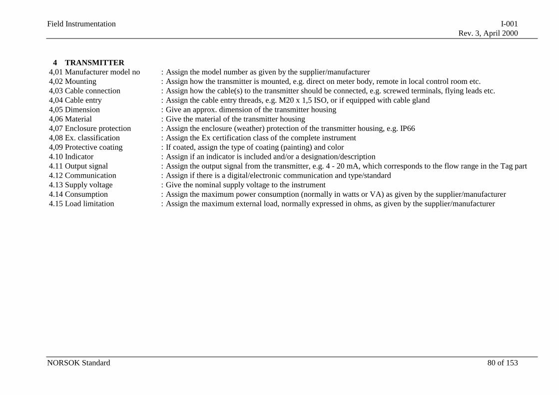
Field Instrumentation I-001Rev. 3, April 2000
NORSOK Standard 80 of 153
4 TRANSMITTER4,01 Manufacturer model no : Assign the model number as given by the supplier/manufacturer4,02 Mounting : Assign how the transmitter is mounted, e.g. direct on meter body, remote in local control room etc.4,03 Cable connection : Assign how the cable(s) to the transmitter should be connected, e.g. screwed terminals, flying leads etc.4,04 Cable entry : Assign the cable entry threads, e.g. M20 x 1,5 ISO, or if equipped with cable gland4,05 Dimension : Give an approx. dimension of the transmitter housing4,06 Material : Give the material of the transmitter housing4,07 Enclosure protection : Assign the enclosure (weather) protection of the transmitter housing, e.g. IP664,08 Ex. classification : Assign the Ex certification class of the complete instrument4,09 Protective coating : If coated, assign the type of coating (painting) and color4.10 Indicator : Assign if an indicator is included and/or a designation/description4.11 Output signal : Assign the output signal from the transmitter, e.g. 4 - 20 mA, which corresponds to the flow range in the Tag part4.12 Communication : Assign if there is a digital/electronic communication and type/standard4.13 Supply voltage : Give the nominal supply voltage to the instrument4.14 Consumption : Assign the maximum power consumption (normally in watts or VA) as given by the supplier/manufacturer4.15 Load limitation : Assign the maximum external load, normally expressed in ohms, as given by the supplier/manufacturer
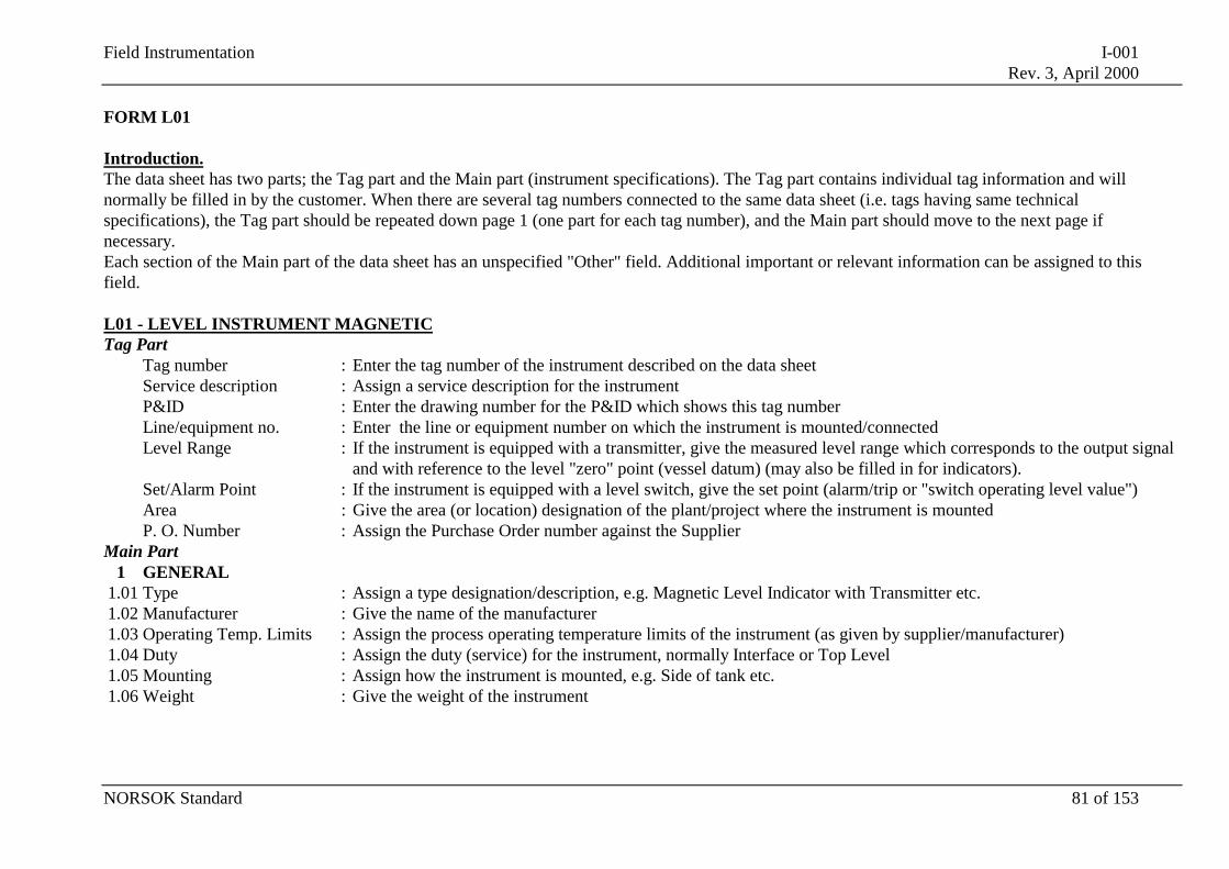
Field Instrumentation I-001Rev. 3, April 2000
NORSOK Standard 81 of 153
FORM L01
Introduction.The data sheet has two parts; the Tag part and the Main part (instrument specifications). The Tag part contains individual tag information and willnormally be filled in by the customer. When there are several tag numbers connected to the same data sheet (i.e. tags having same technicalspecifications), the Tag part should be repeated down page 1 (one part for each tag number), and the Main part should move to the next page ifnecessary.Each section of the Main part of the data sheet has an unspecified "Other" field. Additional important or relevant information can be assigned to thisfield.
L01 - LEVEL INSTRUMENT MAGNETICTag Part
Tag number : Enter the tag number of the instrument described on the data sheetService description : Assign a service description for the instrumentP&ID : Enter the drawing number for the P&ID which shows this tag numberLine/equipment no. : Enter the line or equipment number on which the instrument is mounted/connectedLevel Range : If the instrument is equipped with a transmitter, give the measured level range which corresponds to the output signal
and with reference to the level "zero" point (vessel datum) (may also be filled in for indicators).Set/Alarm Point : If the instrument is equipped with a level switch, give the set point (alarm/trip or "switch operating level value")Area : Give the area (or location) designation of the plant/project where the instrument is mountedP. O. Number : Assign the Purchase Order number against the Supplier
Main Part1 GENERAL
1.01 Type : Assign a type designation/description, e.g. Magnetic Level Indicator with Transmitter etc.1.02 Manufacturer : Give the name of the manufacturer1.03 Operating Temp. Limits : Assign the process operating temperature limits of the instrument (as given by supplier/manufacturer)1.04 Duty : Assign the duty (service) for the instrument, normally Interface or Top Level1.05 Mounting : Assign how the instrument is mounted, e.g. Side of tank etc.1.06 Weight : Give the weight of the instrument
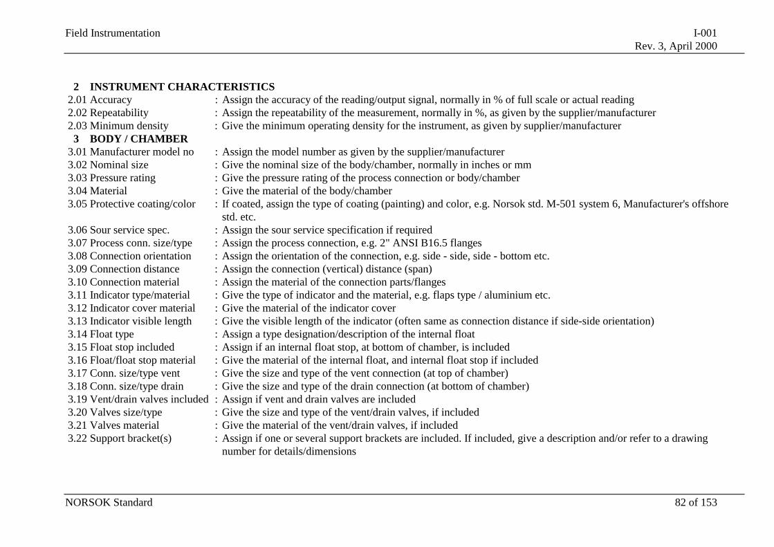
Field Instrumentation I-001Rev. 3, April 2000
NORSOK Standard 82 of 153
2 INSTRUMENT CHARACTERISTICS2.01 Accuracy : Assign the accuracy of the reading/output signal, normally in % of full scale or actual reading2.02 Repeatability : Assign the repeatability of the measurement, normally in %, as given by the supplier/manufacturer2.03 Minimum density : Give the minimum operating density for the instrument, as given by supplier/manufacturer
3 BODY / CHAMBER3.01 Manufacturer model no : Assign the model number as given by the supplier/manufacturer3.02 Nominal size : Give the nominal size of the body/chamber, normally in inches or mm3.03 Pressure rating : Give the pressure rating of the process connection or body/chamber3.04 Material : Give the material of the body/chamber3.05 Protective coating/color : If coated, assign the type of coating (painting) and color, e.g. Norsok std. M-501 system 6, Manufacturer's offshore
std. etc.3.06 Sour service spec. : Assign the sour service specification if required3.07 Process conn. size/type : Assign the process connection, e.g. 2" ANSI B16.5 flanges3.08 Connection orientation : Assign the orientation of the connection, e.g. side - side, side - bottom etc.3.09 Connection distance : Assign the connection (vertical) distance (span)3.10 Connection material : Assign the material of the connection parts/flanges3.11 Indicator type/material : Give the type of indicator and the material, e.g. flaps type / aluminium etc.3.12 Indicator cover material : Give the material of the indicator cover3.13 Indicator visible length : Give the visible length of the indicator (often same as connection distance if side-side orientation)3.14 Float type : Assign a type designation/description of the internal float3.15 Float stop included : Assign if an internal float stop, at bottom of chamber, is included3.16 Float/float stop material : Give the material of the internal float, and internal float stop if included3.17 Conn. size/type vent : Give the size and type of the vent connection (at top of chamber)3.18 Conn. size/type drain : Give the size and type of the drain connection (at bottom of chamber)3.19 Vent/drain valves included : Assign if vent and drain valves are included3.20 Valves size/type : Give the size and type of the vent/drain valves, if included3.21 Valves material : Give the material of the vent/drain valves, if included3.22 Support bracket(s) : Assign if one or several support brackets are included. If included, give a description and/or refer to a drawing
number for details/dimensions
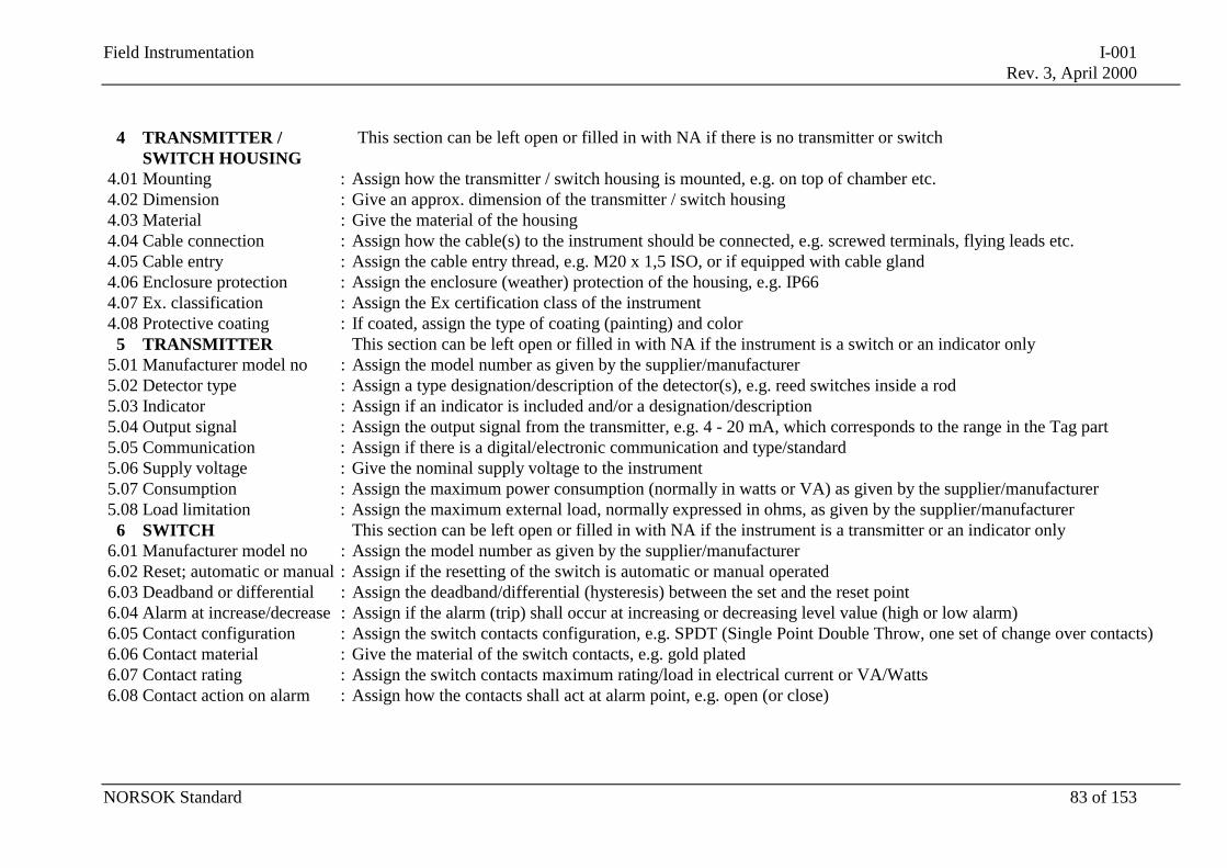
Field Instrumentation I-001Rev. 3, April 2000
NORSOK Standard 83 of 153
4 TRANSMITTER /SWITCH HOUSING
This section can be left open or filled in with NA if there is no transmitter or switch
4.01 Mounting : Assign how the transmitter / switch housing is mounted, e.g. on top of chamber etc.4.02 Dimension : Give an approx. dimension of the transmitter / switch housing4.03 Material : Give the material of the housing4.04 Cable connection : Assign how the cable(s) to the instrument should be connected, e.g. screwed terminals, flying leads etc.4.05 Cable entry : Assign the cable entry thread, e.g. M20 x 1,5 ISO, or if equipped with cable gland4.06 Enclosure protection : Assign the enclosure (weather) protection of the housing, e.g. IP664.07 Ex. classification : Assign the Ex certification class of the instrument4.08 Protective coating : If coated, assign the type of coating (painting) and color
5 TRANSMITTER This section can be left open or filled in with NA if the instrument is a switch or an indicator only5.01 Manufacturer model no : Assign the model number as given by the supplier/manufacturer5.02 Detector type : Assign a type designation/description of the detector(s), e.g. reed switches inside a rod5.03 Indicator : Assign if an indicator is included and/or a designation/description5.04 Output signal : Assign the output signal from the transmitter, e.g. 4 - 20 mA, which corresponds to the range in the Tag part5.05 Communication : Assign if there is a digital/electronic communication and type/standard5.06 Supply voltage : Give the nominal supply voltage to the instrument5.07 Consumption : Assign the maximum power consumption (normally in watts or VA) as given by the supplier/manufacturer5.08 Load limitation : Assign the maximum external load, normally expressed in ohms, as given by the supplier/manufacturer
6 SWITCH This section can be left open or filled in with NA if the instrument is a transmitter or an indicator only6.01 Manufacturer model no : Assign the model number as given by the supplier/manufacturer6.02 Reset; automatic or manual : Assign if the resetting of the switch is automatic or manual operated6.03 Deadband or differential : Assign the deadband/differential (hysteresis) between the set and the reset point6.04 Alarm at increase/decrease : Assign if the alarm (trip) shall occur at increasing or decreasing level value (high or low alarm)6.05 Contact configuration : Assign the switch contacts configuration, e.g. SPDT (Single Point Double Throw, one set of change over contacts)6.06 Contact material : Give the material of the switch contacts, e.g. gold plated6.07 Contact rating : Assign the switch contacts maximum rating/load in electrical current or VA/Watts6.08 Contact action on alarm : Assign how the contacts shall act at alarm point, e.g. open (or close)
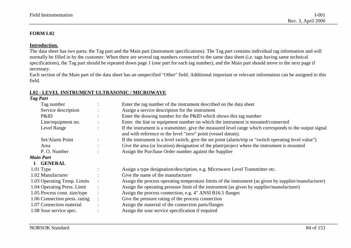
Field Instrumentation I-001Rev. 3, April 2000
NORSOK Standard 84 of 153
FORM L02
Introduction.The data sheet has two parts; the Tag part and the Main part (instrument specifications). The Tag part contains individual tag information and willnormally be filled in by the customer. When there are several tag numbers connected to the same data sheet (i.e. tags having same technicalspecifications), the Tag part should be repeated down page 1 (one part for each tag number), and the Main part should move to the next page ifnecessary.Each section of the Main part of the data sheet has an unspecified "Other" field. Additional important or relevant information can be assigned to thisfield.
L02 - LEVEL INSTRUMENT ULTRASONIC / MICROWAVETag Part
Tag number : Enter the tag number of the instrument described on the data sheetService description : Assign a service description for the instrumentP&ID : Enter the drawing number for the P&ID which shows this tag numberLine/equipment no. : Enter the line or equipment number on which the instrument is mounted/connectedLevel Range : If the instrument is a transmitter, give the measured level range which corresponds to the output signal
and with reference to the level "zero" point (vessel datum).Set/Alarm Point : If the instrument is a level switch, give the set point (alarm/trip or "switch operating level value")Area : Give the area (or location) designation of the plant/project where the instrument is mountedP. O. Number : Assign the Purchase Order number against the Supplier
Main Part1 GENERAL
1.01 Type : Assign a type designation/description, e.g. Microwave Level Transmitter etc.1.02 Manufacturer : Give the name of the manufacturer1.03 Operating Temp. Limits : Assign the process operating temperature limits of the instrument (as given by supplier/manufacturer)1.04 Operating Press. Limit : Assign the operating pressure limit of the instrument (as given by supplier/manufacturer)1.05 Process conn. size/type : Assign the process connection, e.g. 4" ANSI B16.5 flanges1.06 Connection press. rating : Give the pressure rating of the process connection1.07 Connection material : Assign the material of the connection parts/flanges1.08 Sour service spec. : Assign the sour service specification if required
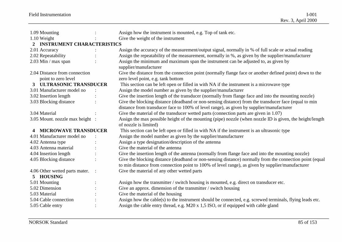
Field Instrumentation I-001Rev. 3, April 2000
NORSOK Standard 85 of 153
1.09 Mounting : Assign how the instrument is mounted, e.g. Top of tank etc.1.10 Weight : Give the weight of the instrument
2 INSTRUMENT CHARACTERISTICS2.01 Accuracy : Assign the accuracy of the measurement/output signal, normally in % of full scale or actual reading2.02 Repeatability : Assign the repeatability of the measurement, normally in %, as given by the supplier/manufacturer2.03 Min / max span : Assign the minimum and maximum span the instrument can be adjusted to, as given by
supplier/manufacturer2.04 Distance from connection
point to zero levelGive the distance from the connection point (normally flange face or another defined point) down to thezero level point, e.g. tank bottom
3 ULTRASONIC TRANSDUCER This section can be left open or filled in with NA if the instrument is a microwave type3.01 Manufacturer model no : Assign the model number as given by the supplier/manufacturer3.02 Insertion length : Give the insertion length of the transducer (normally from flange face and into the mounting nozzle)3.03 Blocking distance : Give the blocking distance (deadband or non-sensing distance) from the transducer face (equal to min
distance from transducer face to 100% of level range), as given by supplier/manufacturer3.04 Material : Give the material of the transducer wetted parts (connection parts are given in 1.07)3.05 Mount. nozzle max height : Assign the max possible height of the mounting (pipe) nozzle (when nozzle ID is given, the height/length
of nozzle is limited)4 MICROWAVE TRANSDUCER This section can be left open or filled in with NA if the instrument is an ultrasonic type
4.01 Manufacturer model no : Assign the model number as given by the supplier/manufacturer4.02 Antenna type : Assign a type designation/description of the antenna4.03 Antenna material : Give the material of the antenna4.04 Insertion length : Give the insertion length of the antenna (normally from flange face and into the mounting nozzle)4.05 Blocking distance : Give the blocking distance (deadband or non-sensing distance) normally from the connection point (equal
to min distance from connection point to 100% of level range), as given by supplier/manufacturer4.06 Other wetted parts mater. : Give the material of any other wetted parts
5 HOUSING5.01 Mounting : Assign how the transmitter / switch housing is mounted, e.g. direct on transducer etc.5.02 Dimension : Give an approx. dimension of the transmitter / switch housing5.03 Material : Give the material of the housing5.04 Cable connection : Assign how the cable(s) to the instrument should be connected, e.g. screwed terminals, flying leads etc.5.05 Cable entry : Assign the cable entry thread, e.g. M20 x 1,5 ISO, or if equipped with cable gland
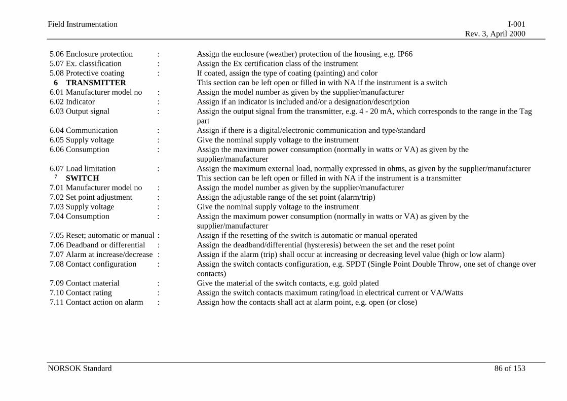
Field Instrumentation I-001Rev. 3, April 2000
NORSOK Standard 86 of 153
5.06 Enclosure protection : Assign the enclosure (weather) protection of the housing, e.g. IP665.07 Ex. classification : Assign the Ex certification class of the instrument5.08 Protective coating : If coated, assign the type of coating (painting) and color
6 TRANSMITTER This section can be left open or filled in with NA if the instrument is a switch6.01 Manufacturer model no : Assign the model number as given by the supplier/manufacturer6.02 Indicator : Assign if an indicator is included and/or a designation/description6.03 Output signal : Assign the output signal from the transmitter, e.g. 4 - 20 mA, which corresponds to the range in the Tag
part6.04 Communication : Assign if there is a digital/electronic communication and type/standard6.05 Supply voltage : Give the nominal supply voltage to the instrument6.06 Consumption : Assign the maximum power consumption (normally in watts or VA) as given by the
supplier/manufacturer6.07 Load limitation : Assign the maximum external load, normally expressed in ohms, as given by the supplier/manufacturer
7 SWITCH This section can be left open or filled in with NA if the instrument is a transmitter7.01 Manufacturer model no : Assign the model number as given by the supplier/manufacturer7.02 Set point adjustment : Assign the adjustable range of the set point (alarm/trip)7.03 Supply voltage : Give the nominal supply voltage to the instrument7.04 Consumption : Assign the maximum power consumption (normally in watts or VA) as given by the
supplier/manufacturer7.05 Reset; automatic or manual : Assign if the resetting of the switch is automatic or manual operated7.06 Deadband or differential : Assign the deadband/differential (hysteresis) between the set and the reset point7.07 Alarm at increase/decrease : Assign if the alarm (trip) shall occur at increasing or decreasing level value (high or low alarm)7.08 Contact configuration : Assign the switch contacts configuration, e.g. SPDT (Single Point Double Throw, one set of change over
contacts)7.09 Contact material : Give the material of the switch contacts, e.g. gold plated7.10 Contact rating : Assign the switch contacts maximum rating/load in electrical current or VA/Watts7.11 Contact action on alarm : Assign how the contacts shall act at alarm point, e.g. open (or close)
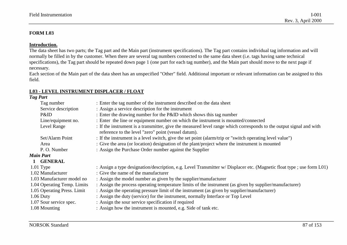
Field Instrumentation I-001Rev. 3, April 2000
NORSOK Standard 87 of 153
FORM L03
Introduction.The data sheet has two parts; the Tag part and the Main part (instrument specifications). The Tag part contains individual tag information and willnormally be filled in by the customer. When there are several tag numbers connected to the same data sheet (i.e. tags having same technicalspecifications), the Tag part should be repeated down page 1 (one part for each tag number), and the Main part should move to the next page ifnecessary.Each section of the Main part of the data sheet has an unspecified "Other" field. Additional important or relevant information can be assigned to thisfield.
L03 - LEVEL INSTRUMENT DISPLACER / FLOATTag Part
Tag number : Enter the tag number of the instrument described on the data sheetService description : Assign a service description for the instrumentP&ID : Enter the drawing number for the P&ID which shows this tag numberLine/equipment no. : Enter the line or equipment number on which the instrument is mounted/connectedLevel Range : If the instrument is a transmitter, give the measured level range which corresponds to the output signal and with
reference to the level "zero" point (vessel datum).Set/Alarm Point : If the instrument is a level switch, give the set point (alarm/trip or "switch operating level value")Area : Give the area (or location) designation of the plant/project where the instrument is mountedP. O. Number : Assign the Purchase Order number against the Supplier
Main Part1 GENERAL
1.01 Type : Assign a type designation/description, e.g. Level Transmitter w/ Displacer etc. (Magnetic float type ; use form L01)1.02 Manufacturer : Give the name of the manufacturer1.03 Manufacturer model no : Assign the model number as given by the supplier/manufacturer1.04 Operating Temp. Limits : Assign the process operating temperature limits of the instrument (as given by supplier/manufacturer)1.05 Operating Press. Limit : Assign the operating pressure limit of the instrument (as given by supplier/manufacturer)1.06 Duty : Assign the duty (service) for the instrument, normally Interface or Top Level1.07 Sour service spec. : Assign the sour service specification if required1.08 Mounting : Assign how the instrument is mounted, e.g. Side of tank etc.
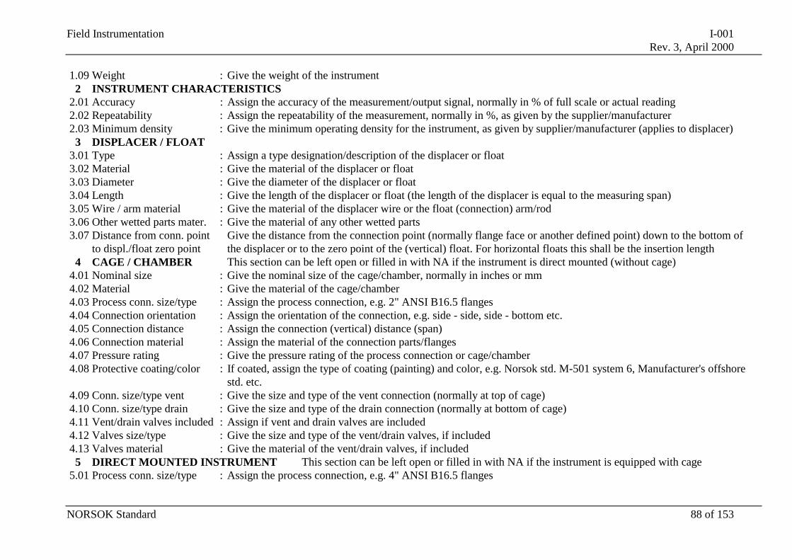
Field Instrumentation I-001Rev. 3, April 2000
NORSOK Standard 88 of 153
1.09 Weight : Give the weight of the instrument2 INSTRUMENT CHARACTERISTICS
2.01 Accuracy : Assign the accuracy of the measurement/output signal, normally in % of full scale or actual reading2.02 Repeatability : Assign the repeatability of the measurement, normally in %, as given by the supplier/manufacturer2.03 Minimum density : Give the minimum operating density for the instrument, as given by supplier/manufacturer (applies to displacer)
3 DISPLACER / FLOAT3.01 Type : Assign a type designation/description of the displacer or float3.02 Material : Give the material of the displacer or float3.03 Diameter : Give the diameter of the displacer or float3.04 Length : Give the length of the displacer or float (the length of the displacer is equal to the measuring span)3.05 Wire / arm material : Give the material of the displacer wire or the float (connection) arm/rod3.06 Other wetted parts mater. : Give the material of any other wetted parts3.07 Distance from conn. point
to displ./float zero pointGive the distance from the connection point (normally flange face or another defined point) down to the bottom ofthe displacer or to the zero point of the (vertical) float. For horizontal floats this shall be the insertion length
4 CAGE / CHAMBER This section can be left open or filled in with NA if the instrument is direct mounted (without cage)4.01 Nominal size : Give the nominal size of the cage/chamber, normally in inches or mm4.02 Material : Give the material of the cage/chamber4.03 Process conn. size/type : Assign the process connection, e.g. 2" ANSI B16.5 flanges4.04 Connection orientation : Assign the orientation of the connection, e.g. side - side, side - bottom etc.4.05 Connection distance : Assign the connection (vertical) distance (span)4.06 Connection material : Assign the material of the connection parts/flanges4.07 Pressure rating : Give the pressure rating of the process connection or cage/chamber4.08 Protective coating/color : If coated, assign the type of coating (painting) and color, e.g. Norsok std. M-501 system 6, Manufacturer's offshore
std. etc.4.09 Conn. size/type vent : Give the size and type of the vent connection (normally at top of cage)4.10 Conn. size/type drain : Give the size and type of the drain connection (normally at bottom of cage)4.11 Vent/drain valves included : Assign if vent and drain valves are included4.12 Valves size/type : Give the size and type of the vent/drain valves, if included4.13 Valves material : Give the material of the vent/drain valves, if included
5 DIRECT MOUNTED INSTRUMENT This section can be left open or filled in with NA if the instrument is equipped with cage5.01 Process conn. size/type : Assign the process connection, e.g. 4" ANSI B16.5 flanges
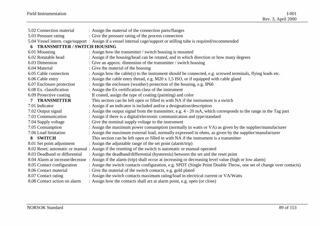
Field Instrumentation I-001Rev. 3, April 2000
NORSOK Standard 89 of 153
5.02 Connection material : Assign the material of the connection parts/flanges5.03 Pressure rating : Give the pressure rating of the process connection5.04 Vessel intern. cage/support : Assign if a vessel internal cage/support or stilling tube is required/recommended
6 TRANSMITTER / SWITCH HOUSING6.01 Mounting : Assign how the transmitter / switch housing is mounted6.02 Rotatable head : Assign if the housing/head can be rotated, and in which direction or how many degrees6.03 Dimension : Give an approx. dimension of the transmitter / switch housing6.04 Material : Give the material of the housing6.05 Cable connection : Assign how the cable(s) to the instrument should be connected, e.g. screwed terminals, flying leads etc.6.06 Cable entry : Assign the cable entry thread, e.g. M20 x 1,5 ISO, or if equipped with cable gland6.07 Enclosure protection : Assign the enclosure (weather) protection of the housing, e.g. IP666.08 Ex. classification : Assign the Ex certification class of the instrument6.09 Protective coating If coated, assign the type of coating (painting) and color
7 TRANSMITTER This section can be left open or filled in with NA if the instrument is a switch7.01 Indicator : Assign if an indicator is included and/or a designation/description7.02 Output signal : Assign the output signal from the transmitter, e.g. 4 - 20 mA, which corresponds to the range in the Tag part7.03 Communication : Assign if there is a digital/electronic communication and type/standard7.04 Supply voltage : Give the nominal supply voltage to the instrument7.05 Consumption : Assign the maximum power consumption (normally in watts or VA) as given by the supplier/manufacturer7.06 Load limitation : Assign the maximum external load, normally expressed in ohms, as given by the supplier/manufacturer
8 SWITCH This section can be left open or filled in with NA if the instrument is a transmitter8.01 Set point adjustment : Assign the adjustable range of the set point (alarm/trip)8.02 Reset; automatic or manual : Assign if the resetting of the switch is automatic or manual operated8.03 Deadband or differential : Assign the deadband/differential (hysteresis) between the set and the reset point8.04 Alarm at increase/decrease : Assign if the alarm (trip) shall occur at increasing or decreasing level value (high or low alarm)8.05 Contact configuration : Assign the switch contacts configuration, e.g. SPDT (Single Point Double Throw, one set of change over contacts)8.06 Contact material : Give the material of the switch contacts, e.g. gold plated8.07 Contact rating : Assign the switch contacts maximum rating/load in electrical current or VA/Watts8.08 Contact action on alarm : Assign how the contacts shall act at alarm point, e.g. open (or close)
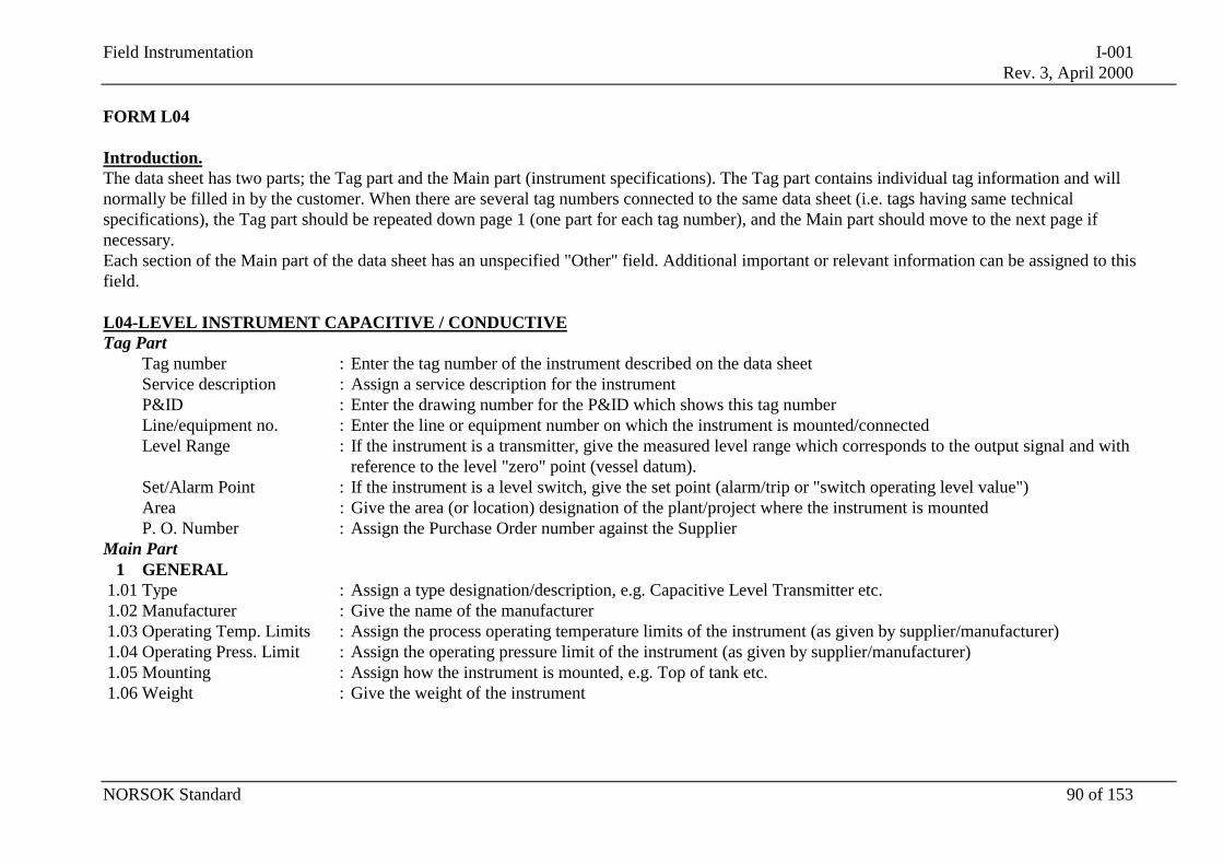
Field Instrumentation I-001Rev. 3, April 2000
NORSOK Standard 90 of 153
FORM L04
Introduction.The data sheet has two parts; the Tag part and the Main part (instrument specifications). The Tag part contains individual tag information and willnormally be filled in by the customer. When there are several tag numbers connected to the same data sheet (i.e. tags having same technicalspecifications), the Tag part should be repeated down page 1 (one part for each tag number), and the Main part should move to the next page ifnecessary.Each section of the Main part of the data sheet has an unspecified "Other" field. Additional important or relevant information can be assigned to thisfield.
L04-LEVEL INSTRUMENT CAPACITIVE / CONDUCTIVETag Part
Tag number : Enter the tag number of the instrument described on the data sheetService description : Assign a service description for the instrumentP&ID : Enter the drawing number for the P&ID which shows this tag numberLine/equipment no. : Enter the line or equipment number on which the instrument is mounted/connectedLevel Range : If the instrument is a transmitter, give the measured level range which corresponds to the output signal and with
reference to the level "zero" point (vessel datum).Set/Alarm Point : If the instrument is a level switch, give the set point (alarm/trip or "switch operating level value")Area : Give the area (or location) designation of the plant/project where the instrument is mountedP. O. Number : Assign the Purchase Order number against the Supplier
Main Part1 GENERAL
1.01 Type : Assign a type designation/description, e.g. Capacitive Level Transmitter etc.1.02 Manufacturer : Give the name of the manufacturer1.03 Operating Temp. Limits : Assign the process operating temperature limits of the instrument (as given by supplier/manufacturer)1.04 Operating Press. Limit : Assign the operating pressure limit of the instrument (as given by supplier/manufacturer)1.05 Mounting : Assign how the instrument is mounted, e.g. Top of tank etc.1.06 Weight : Give the weight of the instrument
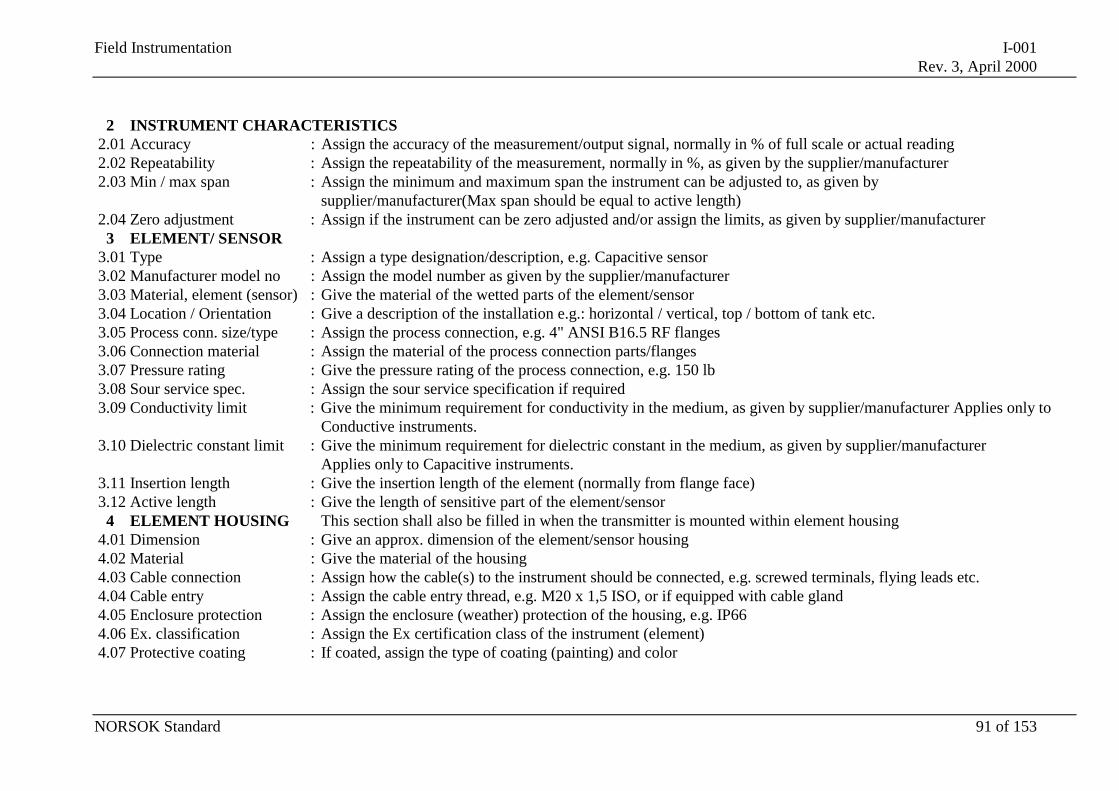
Field Instrumentation I-001Rev. 3, April 2000
NORSOK Standard 91 of 153
2 INSTRUMENT CHARACTERISTICS2.01 Accuracy : Assign the accuracy of the measurement/output signal, normally in % of full scale or actual reading2.02 Repeatability : Assign the repeatability of the measurement, normally in %, as given by the supplier/manufacturer2.03 Min / max span : Assign the minimum and maximum span the instrument can be adjusted to, as given by
supplier/manufacturer(Max span should be equal to active length)2.04 Zero adjustment : Assign if the instrument can be zero adjusted and/or assign the limits, as given by supplier/manufacturer
3 ELEMENT/ SENSOR3.01 Type : Assign a type designation/description, e.g. Capacitive sensor3.02 Manufacturer model no : Assign the model number as given by the supplier/manufacturer3.03 Material, element (sensor) : Give the material of the wetted parts of the element/sensor3.04 Location / Orientation : Give a description of the installation e.g.: horizontal / vertical, top / bottom of tank etc.3.05 Process conn. size/type : Assign the process connection, e.g. 4" ANSI B16.5 RF flanges3.06 Connection material : Assign the material of the process connection parts/flanges3.07 Pressure rating : Give the pressure rating of the process connection, e.g. 150 lb3.08 Sour service spec. : Assign the sour service specification if required3.09 Conductivity limit : Give the minimum requirement for conductivity in the medium, as given by supplier/manufacturer Applies only to
Conductive instruments.3.10 Dielectric constant limit : Give the minimum requirement for dielectric constant in the medium, as given by supplier/manufacturer
Applies only to Capacitive instruments.3.11 Insertion length : Give the insertion length of the element (normally from flange face)3.12 Active length : Give the length of sensitive part of the element/sensor
4 ELEMENT HOUSING This section shall also be filled in when the transmitter is mounted within element housing4.01 Dimension : Give an approx. dimension of the element/sensor housing4.02 Material : Give the material of the housing4.03 Cable connection : Assign how the cable(s) to the instrument should be connected, e.g. screwed terminals, flying leads etc.4.04 Cable entry : Assign the cable entry thread, e.g. M20 x 1,5 ISO, or if equipped with cable gland4.05 Enclosure protection : Assign the enclosure (weather) protection of the housing, e.g. IP664.06 Ex. classification : Assign the Ex certification class of the instrument (element)4.07 Protective coating : If coated, assign the type of coating (painting) and color
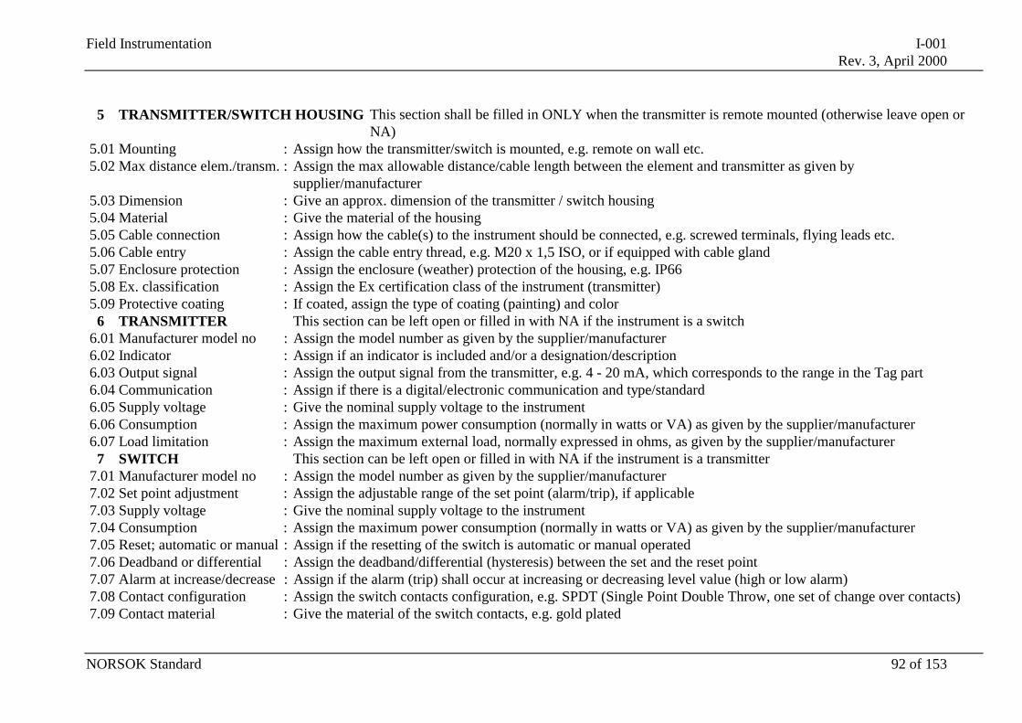
Field Instrumentation I-001Rev. 3, April 2000
NORSOK Standard 92 of 153
5 TRANSMITTER/SWITCH HOUSING This section shall be filled in ONLY when the transmitter is remote mounted (otherwise leave open orNA)
5.01 Mounting : Assign how the transmitter/switch is mounted, e.g. remote on wall etc.5.02 Max distance elem./transm. : Assign the max allowable distance/cable length between the element and transmitter as given by
supplier/manufacturer5.03 Dimension : Give an approx. dimension of the transmitter / switch housing5.04 Material : Give the material of the housing5.05 Cable connection : Assign how the cable(s) to the instrument should be connected, e.g. screwed terminals, flying leads etc.5.06 Cable entry : Assign the cable entry thread, e.g. M20 x 1,5 ISO, or if equipped with cable gland5.07 Enclosure protection : Assign the enclosure (weather) protection of the housing, e.g. IP665.08 Ex. classification : Assign the Ex certification class of the instrument (transmitter)5.09 Protective coating : If coated, assign the type of coating (painting) and color
6 TRANSMITTER This section can be left open or filled in with NA if the instrument is a switch6.01 Manufacturer model no : Assign the model number as given by the supplier/manufacturer6.02 Indicator : Assign if an indicator is included and/or a designation/description6.03 Output signal : Assign the output signal from the transmitter, e.g. 4 - 20 mA, which corresponds to the range in the Tag part6.04 Communication : Assign if there is a digital/electronic communication and type/standard6.05 Supply voltage : Give the nominal supply voltage to the instrument6.06 Consumption : Assign the maximum power consumption (normally in watts or VA) as given by the supplier/manufacturer6.07 Load limitation : Assign the maximum external load, normally expressed in ohms, as given by the supplier/manufacturer
7 SWITCH This section can be left open or filled in with NA if the instrument is a transmitter7.01 Manufacturer model no : Assign the model number as given by the supplier/manufacturer7.02 Set point adjustment : Assign the adjustable range of the set point (alarm/trip), if applicable7.03 Supply voltage : Give the nominal supply voltage to the instrument7.04 Consumption : Assign the maximum power consumption (normally in watts or VA) as given by the supplier/manufacturer7.05 Reset; automatic or manual : Assign if the resetting of the switch is automatic or manual operated7.06 Deadband or differential : Assign the deadband/differential (hysteresis) between the set and the reset point7.07 Alarm at increase/decrease : Assign if the alarm (trip) shall occur at increasing or decreasing level value (high or low alarm)7.08 Contact configuration : Assign the switch contacts configuration, e.g. SPDT (Single Point Double Throw, one set of change over contacts)7.09 Contact material : Give the material of the switch contacts, e.g. gold plated
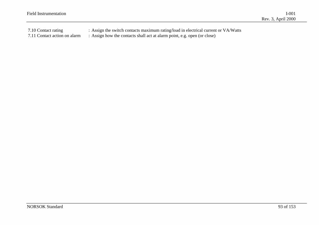
Field Instrumentation I-001Rev. 3, April 2000
NORSOK Standard 93 of 153
7.10 Contact rating : Assign the switch contacts maximum rating/load in electrical current or VA/Watts7.11 Contact action on alarm : Assign how the contacts shall act at alarm point, e.g. open (or close)
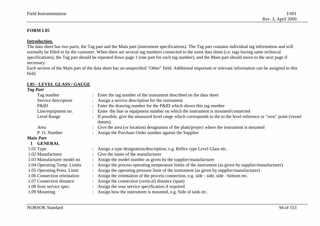
Field Instrumentation I-001Rev. 3, April 2000
NORSOK Standard 94 of 153
FORM L05
Introduction.The data sheet has two parts; the Tag part and the Main part (instrument specifications). The Tag part contains individual tag information and willnormally be filled in by the customer. When there are several tag numbers connected to the same data sheet (i.e. tags having same technicalspecifications), the Tag part should be repeated down page 1 (one part for each tag number), and the Main part should move to the next page ifnecessary.Each section of the Main part of the data sheet has an unspecified "Other" field. Additional important or relevant information can be assigned to thisfield.
L05 - LEVEL GLASS / GAUGETag Part
Tag number : Enter the tag number of the instrument described on the data sheetService description : Assign a service description for the instrumentP&ID : Enter the drawing number for the P&ID which shows this tag numberLine/equipment no. : Enter the line or equipment number on which the instrument is mounted/connectedLevel Range : If possible, give the measured level range which corresponds to the to the level reference or "zero" point (vessel
datum).Area : Give the area (or location) designation of the plant/project where the instrument is mountedP. O. Number : Assign the Purchase Order number against the Supplier
Main Part1 GENERAL
1.01 Type : Assign a type designation/description, e.g. Reflex type Level Glass etc.1.02 Manufacturer : Give the name of the manufacturer1.03 Manufacturer model no : Assign the model number as given by the supplier/manufacturer1.04 Operating Temp. Limits : Assign the process operating temperature limits of the instrument (as given by supplier/manufacturer)1.05 Operating Press. Limit : Assign the operating pressure limit of the instrument (as given by supplier/manufacturer)1.06 Connection orientation : Assign the orientation of the process connection, e.g. side - side, side - bottom etc.1.07 Connection distance : Assign the connection (vertical) distance (span)1.08 Sour service spec. : Assign the sour service specification if required1.09 Mounting : Assign how the instrument is mounted, e.g. Side of tank etc.
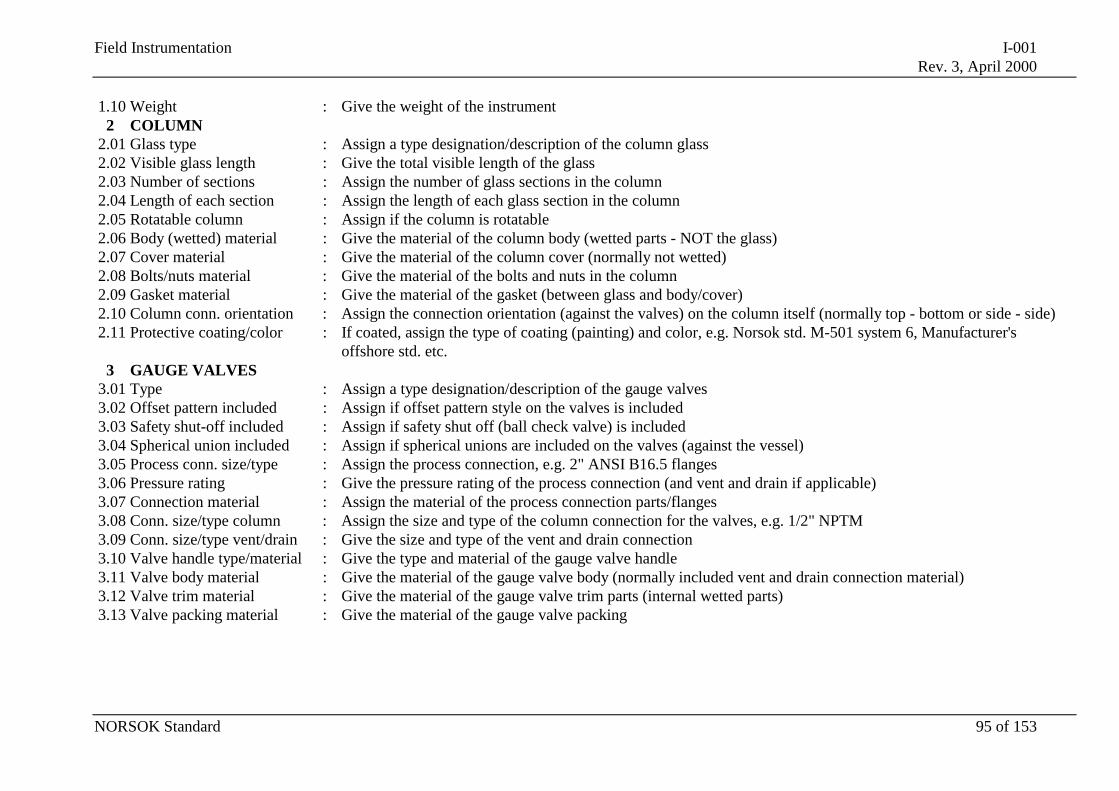
Field Instrumentation I-001Rev. 3, April 2000
NORSOK Standard 95 of 153
1.10 Weight : Give the weight of the instrument2 COLUMN
2.01 Glass type : Assign a type designation/description of the column glass2.02 Visible glass length : Give the total visible length of the glass2.03 Number of sections : Assign the number of glass sections in the column2.04 Length of each section : Assign the length of each glass section in the column2.05 Rotatable column : Assign if the column is rotatable2.06 Body (wetted) material : Give the material of the column body (wetted parts - NOT the glass)2.07 Cover material : Give the material of the column cover (normally not wetted)2.08 Bolts/nuts material : Give the material of the bolts and nuts in the column2.09 Gasket material : Give the material of the gasket (between glass and body/cover)2.10 Column conn. orientation : Assign the connection orientation (against the valves) on the column itself (normally top - bottom or side - side)2.11 Protective coating/color : If coated, assign the type of coating (painting) and color, e.g. Norsok std. M-501 system 6, Manufacturer's
offshore std. etc.3 GAUGE VALVES
3.01 Type : Assign a type designation/description of the gauge valves3.02 Offset pattern included : Assign if offset pattern style on the valves is included3.03 Safety shut-off included : Assign if safety shut off (ball check valve) is included3.04 Spherical union included : Assign if spherical unions are included on the valves (against the vessel)3.05 Process conn. size/type : Assign the process connection, e.g. 2" ANSI B16.5 flanges3.06 Pressure rating : Give the pressure rating of the process connection (and vent and drain if applicable)3.07 Connection material : Assign the material of the process connection parts/flanges3.08 Conn. size/type column : Assign the size and type of the column connection for the valves, e.g. 1/2" NPTM3.09 Conn. size/type vent/drain : Give the size and type of the vent and drain connection3.10 Valve handle type/material : Give the type and material of the gauge valve handle3.11 Valve body material : Give the material of the gauge valve body (normally included vent and drain connection material)3.12 Valve trim material : Give the material of the gauge valve trim parts (internal wetted parts)3.13 Valve packing material : Give the material of the gauge valve packing
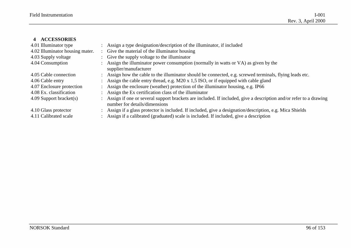
Field Instrumentation I-001Rev. 3, April 2000
NORSOK Standard 96 of 153
4 ACCESSORIES4.01 Illuminator type : Assign a type designation/description of the illuminator, if included4.02 Illuminator housing mater. : Give the material of the illuminator housing4.03 Supply voltage : Give the supply voltage to the illuminator4.04 Consumption : Assign the illuminator power consumption (normally in watts or VA) as given by the
supplier/manufacturer4.05 Cable connection : Assign how the cable to the illuminator should be connected, e.g. screwed terminals, flying leads etc.4.06 Cable entry : Assign the cable entry thread, e.g. M20 x 1,5 ISO, or if equipped with cable gland4.07 Enclosure protection : Assign the enclosure (weather) protection of the illuminator housing, e.g. IP664.08 Ex. classification : Assign the Ex certification class of the illuminator4.09 Support bracket(s) : Assign if one or several support brackets are included. If included, give a description and/or refer to a drawing
number for details/dimensions4.10 Glass protector : Assign if a glass protector is included. If included, give a designation/description, e.g. Mica Shields4.11 Calibrated scale : Assign if a calibrated (graduated) scale is included. If included, give a description
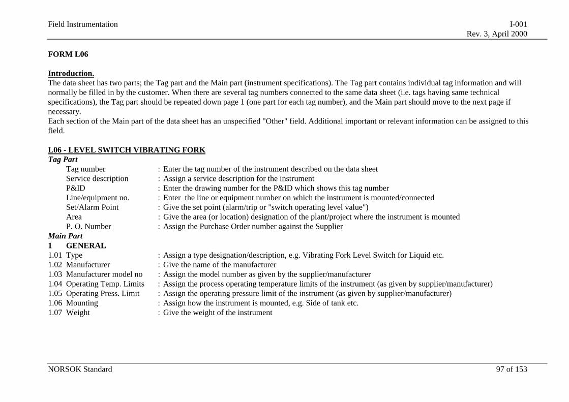
Field Instrumentation I-001Rev. 3, April 2000
NORSOK Standard 97 of 153
FORM L06
Introduction.The data sheet has two parts; the Tag part and the Main part (instrument specifications). The Tag part contains individual tag information and willnormally be filled in by the customer. When there are several tag numbers connected to the same data sheet (i.e. tags having same technicalspecifications), the Tag part should be repeated down page 1 (one part for each tag number), and the Main part should move to the next page ifnecessary.Each section of the Main part of the data sheet has an unspecified "Other" field. Additional important or relevant information can be assigned to thisfield.
L06 - LEVEL SWITCH VIBRATING FORKTag Part
Tag number : Enter the tag number of the instrument described on the data sheetService description : Assign a service description for the instrumentP&ID : Enter the drawing number for the P&ID which shows this tag numberLine/equipment no. : Enter the line or equipment number on which the instrument is mounted/connectedSet/Alarm Point : Give the set point (alarm/trip or "switch operating level value")Area : Give the area (or location) designation of the plant/project where the instrument is mountedP. O. Number : Assign the Purchase Order number against the Supplier
Main Part1 GENERAL1.01 Type : Assign a type designation/description, e.g. Vibrating Fork Level Switch for Liquid etc.1.02 Manufacturer : Give the name of the manufacturer1.03 Manufacturer model no : Assign the model number as given by the supplier/manufacturer1.04 Operating Temp. Limits : Assign the process operating temperature limits of the instrument (as given by supplier/manufacturer)1.05 Operating Press. Limit : Assign the operating pressure limit of the instrument (as given by supplier/manufacturer)1.06 Mounting : Assign how the instrument is mounted, e.g. Side of tank etc.1.07 Weight : Give the weight of the instrument
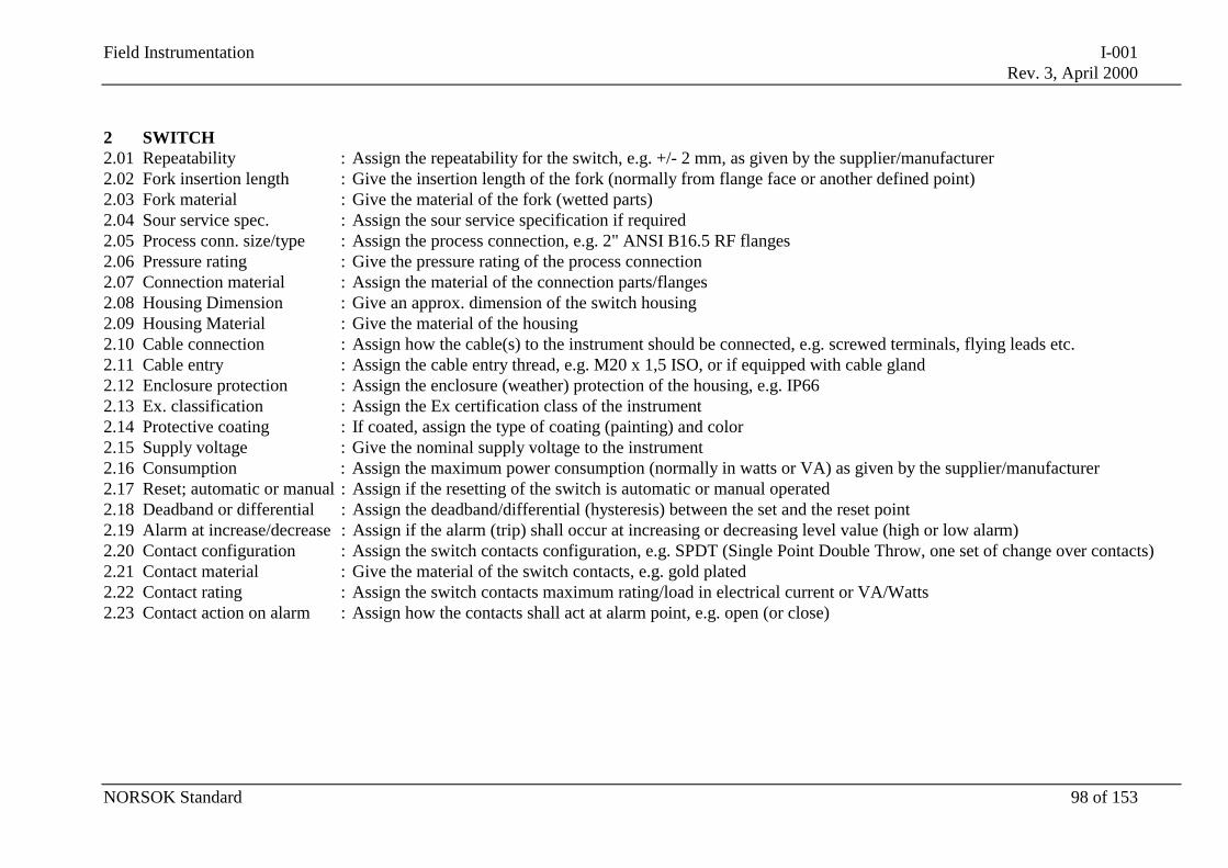
Field Instrumentation I-001Rev. 3, April 2000
NORSOK Standard 98 of 153
2 SWITCH2.01 Repeatability : Assign the repeatability for the switch, e.g. +/- 2 mm, as given by the supplier/manufacturer2.02 Fork insertion length : Give the insertion length of the fork (normally from flange face or another defined point)2.03 Fork material : Give the material of the fork (wetted parts)2.04 Sour service spec. : Assign the sour service specification if required2.05 Process conn. size/type : Assign the process connection, e.g. 2" ANSI B16.5 RF flanges2.06 Pressure rating : Give the pressure rating of the process connection2.07 Connection material : Assign the material of the connection parts/flanges2.08 Housing Dimension : Give an approx. dimension of the switch housing2.09 Housing Material : Give the material of the housing2.10 Cable connection : Assign how the cable(s) to the instrument should be connected, e.g. screwed terminals, flying leads etc.2.11 Cable entry : Assign the cable entry thread, e.g. M20 x 1,5 ISO, or if equipped with cable gland2.12 Enclosure protection : Assign the enclosure (weather) protection of the housing, e.g. IP662.13 Ex. classification : Assign the Ex certification class of the instrument2.14 Protective coating : If coated, assign the type of coating (painting) and color2.15 Supply voltage : Give the nominal supply voltage to the instrument2.16 Consumption : Assign the maximum power consumption (normally in watts or VA) as given by the supplier/manufacturer2.17 Reset; automatic or manual : Assign if the resetting of the switch is automatic or manual operated2.18 Deadband or differential : Assign the deadband/differential (hysteresis) between the set and the reset point2.19 Alarm at increase/decrease : Assign if the alarm (trip) shall occur at increasing or decreasing level value (high or low alarm)2.20 Contact configuration : Assign the switch contacts configuration, e.g. SPDT (Single Point Double Throw, one set of change over contacts)2.21 Contact material : Give the material of the switch contacts, e.g. gold plated2.22 Contact rating : Assign the switch contacts maximum rating/load in electrical current or VA/Watts2.23 Contact action on alarm : Assign how the contacts shall act at alarm point, e.g. open (or close)
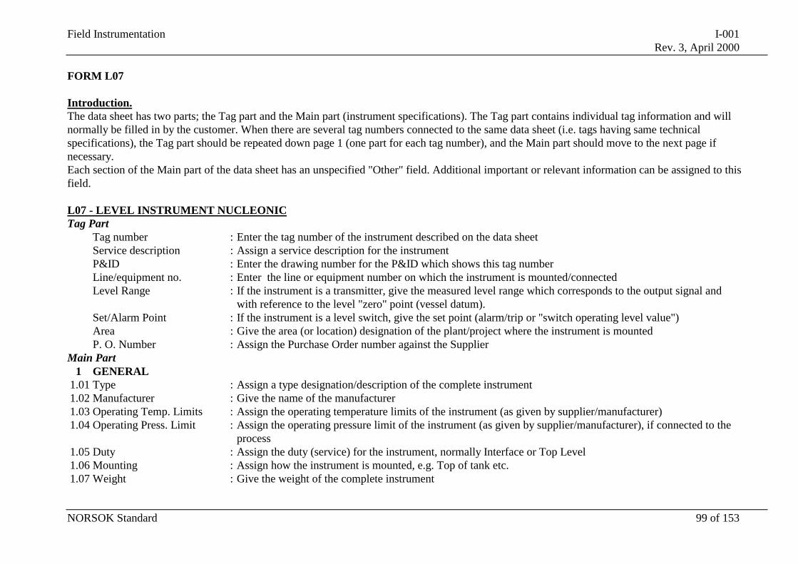
Field Instrumentation I-001Rev. 3, April 2000
NORSOK Standard 99 of 153
FORM L07
Introduction.The data sheet has two parts; the Tag part and the Main part (instrument specifications). The Tag part contains individual tag information and willnormally be filled in by the customer. When there are several tag numbers connected to the same data sheet (i.e. tags having same technicalspecifications), the Tag part should be repeated down page 1 (one part for each tag number), and the Main part should move to the next page ifnecessary.Each section of the Main part of the data sheet has an unspecified "Other" field. Additional important or relevant information can be assigned to thisfield.
L07 - LEVEL INSTRUMENT NUCLEONICTag Part
Tag number : Enter the tag number of the instrument described on the data sheetService description : Assign a service description for the instrumentP&ID : Enter the drawing number for the P&ID which shows this tag numberLine/equipment no. : Enter the line or equipment number on which the instrument is mounted/connectedLevel Range : If the instrument is a transmitter, give the measured level range which corresponds to the output signal and
with reference to the level "zero" point (vessel datum).Set/Alarm Point : If the instrument is a level switch, give the set point (alarm/trip or "switch operating level value")Area : Give the area (or location) designation of the plant/project where the instrument is mountedP. O. Number : Assign the Purchase Order number against the Supplier
Main Part1 GENERAL
1.01 Type : Assign a type designation/description of the complete instrument1.02 Manufacturer : Give the name of the manufacturer1.03 Operating Temp. Limits : Assign the operating temperature limits of the instrument (as given by supplier/manufacturer)1.04 Operating Press. Limit : Assign the operating pressure limit of the instrument (as given by supplier/manufacturer), if connected to the
process1.05 Duty : Assign the duty (service) for the instrument, normally Interface or Top Level1.06 Mounting : Assign how the instrument is mounted, e.g. Top of tank etc.1.07 Weight : Give the weight of the complete instrument
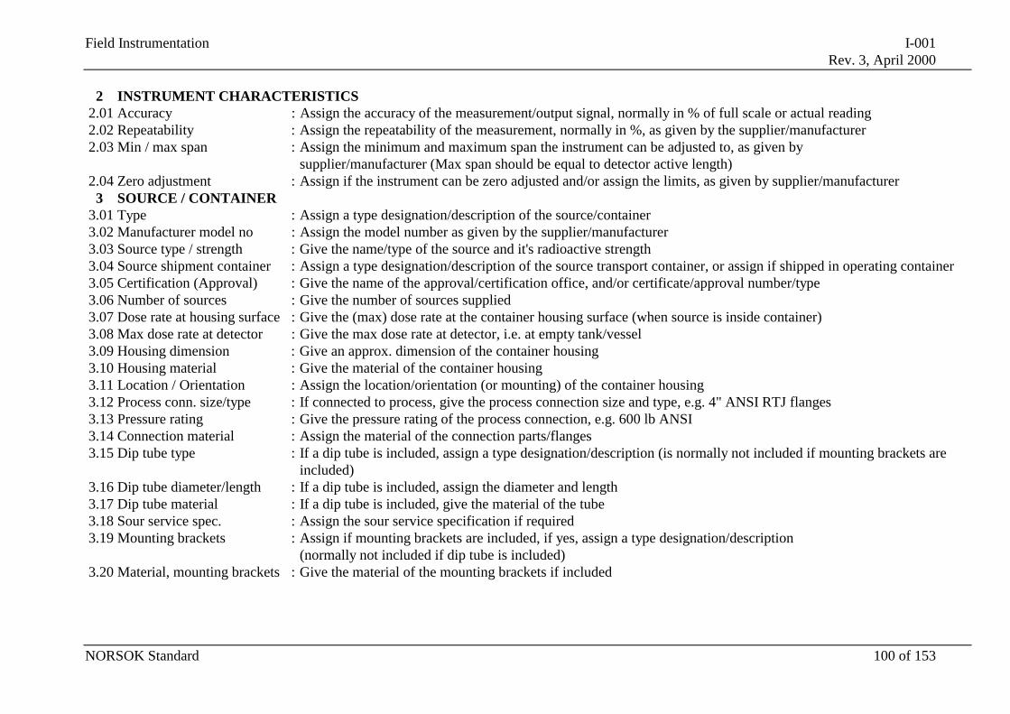
Field Instrumentation I-001Rev. 3, April 2000
NORSOK Standard 100 of 153
2 INSTRUMENT CHARACTERISTICS2.01 Accuracy : Assign the accuracy of the measurement/output signal, normally in % of full scale or actual reading2.02 Repeatability : Assign the repeatability of the measurement, normally in %, as given by the supplier/manufacturer2.03 Min / max span : Assign the minimum and maximum span the instrument can be adjusted to, as given by
supplier/manufacturer (Max span should be equal to detector active length)2.04 Zero adjustment : Assign if the instrument can be zero adjusted and/or assign the limits, as given by supplier/manufacturer
3 SOURCE / CONTAINER3.01 Type : Assign a type designation/description of the source/container3.02 Manufacturer model no : Assign the model number as given by the supplier/manufacturer3.03 Source type / strength : Give the name/type of the source and it's radioactive strength3.04 Source shipment container : Assign a type designation/description of the source transport container, or assign if shipped in operating container3.05 Certification (Approval) : Give the name of the approval/certification office, and/or certificate/approval number/type3.06 Number of sources : Give the number of sources supplied3.07 Dose rate at housing surface : Give the (max) dose rate at the container housing surface (when source is inside container)3.08 Max dose rate at detector : Give the max dose rate at detector, i.e. at empty tank/vessel3.09 Housing dimension : Give an approx. dimension of the container housing3.10 Housing material : Give the material of the container housing3.11 Location / Orientation : Assign the location/orientation (or mounting) of the container housing3.12 Process conn. size/type : If connected to process, give the process connection size and type, e.g. 4" ANSI RTJ flanges3.13 Pressure rating : Give the pressure rating of the process connection, e.g. 600 lb ANSI3.14 Connection material : Assign the material of the connection parts/flanges3.15 Dip tube type : If a dip tube is included, assign a type designation/description (is normally not included if mounting brackets are
included)3.16 Dip tube diameter/length : If a dip tube is included, assign the diameter and length3.17 Dip tube material : If a dip tube is included, give the material of the tube3.18 Sour service spec. : Assign the sour service specification if required3.19 Mounting brackets : Assign if mounting brackets are included, if yes, assign a type designation/description
(normally not included if dip tube is included)3.20 Material, mounting brackets : Give the material of the mounting brackets if included
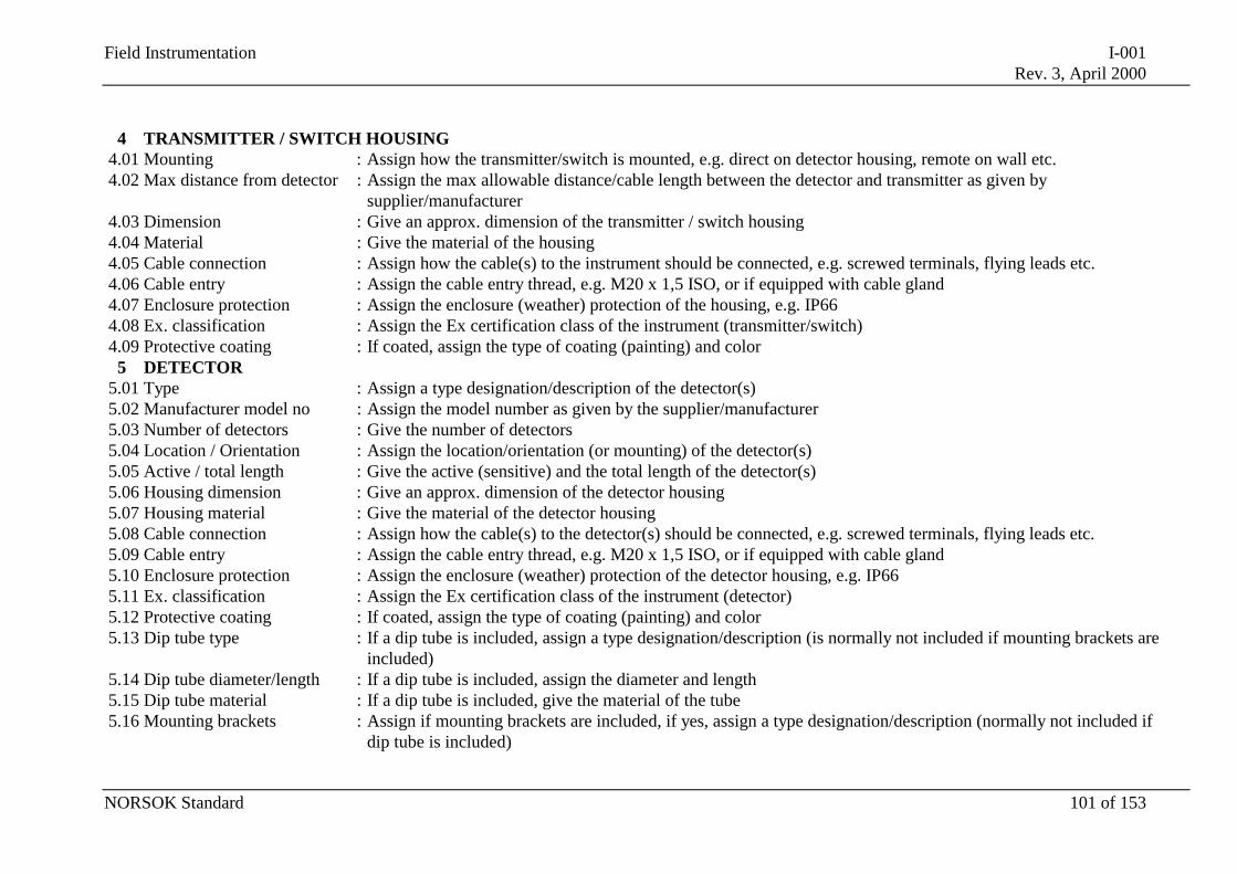
Field Instrumentation I-001Rev. 3, April 2000
NORSOK Standard 101 of 153
4 TRANSMITTER / SWITCH HOUSING4.01 Mounting : Assign how the transmitter/switch is mounted, e.g. direct on detector housing, remote on wall etc.4.02 Max distance from detector : Assign the max allowable distance/cable length between the detector and transmitter as given by
supplier/manufacturer4.03 Dimension : Give an approx. dimension of the transmitter / switch housing4.04 Material : Give the material of the housing4.05 Cable connection : Assign how the cable(s) to the instrument should be connected, e.g. screwed terminals, flying leads etc.4.06 Cable entry : Assign the cable entry thread, e.g. M20 x 1,5 ISO, or if equipped with cable gland4.07 Enclosure protection : Assign the enclosure (weather) protection of the housing, e.g. IP664.08 Ex. classification : Assign the Ex certification class of the instrument (transmitter/switch)4.09 Protective coating : If coated, assign the type of coating (painting) and color
5 DETECTOR5.01 Type : Assign a type designation/description of the detector(s)5.02 Manufacturer model no : Assign the model number as given by the supplier/manufacturer5.03 Number of detectors : Give the number of detectors5.04 Location / Orientation : Assign the location/orientation (or mounting) of the detector(s)5.05 Active / total length : Give the active (sensitive) and the total length of the detector(s)5.06 Housing dimension : Give an approx. dimension of the detector housing5.07 Housing material : Give the material of the detector housing5.08 Cable connection : Assign how the cable(s) to the detector(s) should be connected, e.g. screwed terminals, flying leads etc.5.09 Cable entry : Assign the cable entry thread, e.g. M20 x 1,5 ISO, or if equipped with cable gland5.10 Enclosure protection : Assign the enclosure (weather) protection of the detector housing, e.g. IP665.11 Ex. classification : Assign the Ex certification class of the instrument (detector)5.12 Protective coating : If coated, assign the type of coating (painting) and color5.13 Dip tube type : If a dip tube is included, assign a type designation/description (is normally not included if mounting brackets are
included)5.14 Dip tube diameter/length : If a dip tube is included, assign the diameter and length5.15 Dip tube material : If a dip tube is included, give the material of the tube5.16 Mounting brackets : Assign if mounting brackets are included, if yes, assign a type designation/description (normally not included if
dip tube is included)
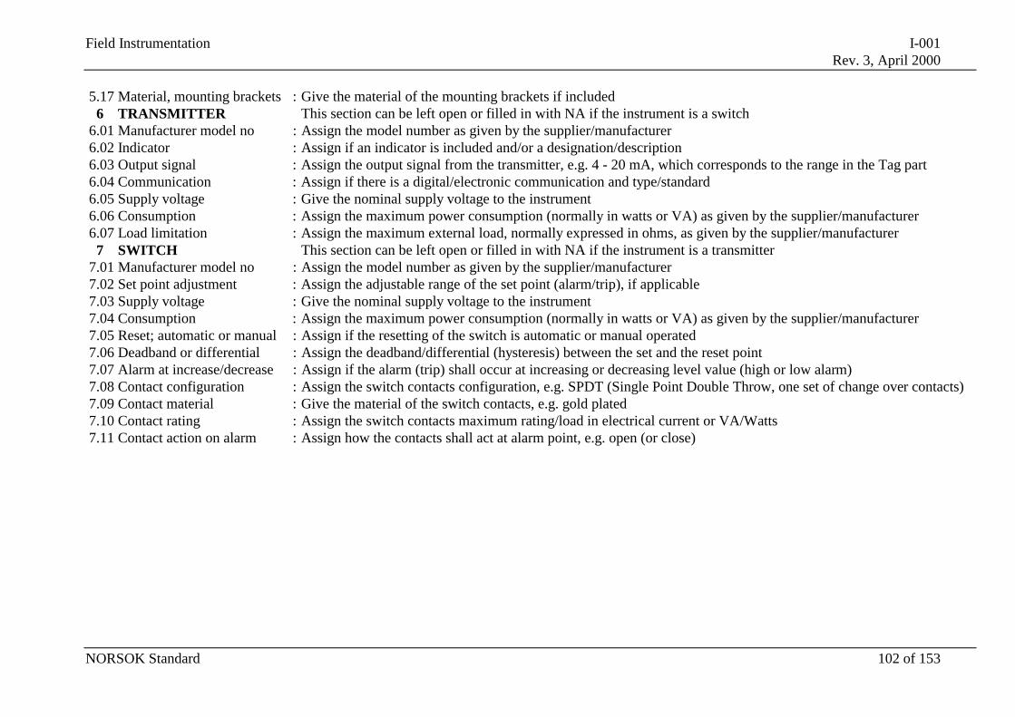
Field Instrumentation I-001Rev. 3, April 2000
NORSOK Standard 102 of 153
5.17 Material, mounting brackets : Give the material of the mounting brackets if included6 TRANSMITTER This section can be left open or filled in with NA if the instrument is a switch
6.01 Manufacturer model no : Assign the model number as given by the supplier/manufacturer6.02 Indicator : Assign if an indicator is included and/or a designation/description6.03 Output signal : Assign the output signal from the transmitter, e.g. 4 - 20 mA, which corresponds to the range in the Tag part6.04 Communication : Assign if there is a digital/electronic communication and type/standard6.05 Supply voltage : Give the nominal supply voltage to the instrument6.06 Consumption : Assign the maximum power consumption (normally in watts or VA) as given by the supplier/manufacturer6.07 Load limitation : Assign the maximum external load, normally expressed in ohms, as given by the supplier/manufacturer
7 SWITCH This section can be left open or filled in with NA if the instrument is a transmitter7.01 Manufacturer model no : Assign the model number as given by the supplier/manufacturer7.02 Set point adjustment : Assign the adjustable range of the set point (alarm/trip), if applicable7.03 Supply voltage : Give the nominal supply voltage to the instrument7.04 Consumption : Assign the maximum power consumption (normally in watts or VA) as given by the supplier/manufacturer7.05 Reset; automatic or manual : Assign if the resetting of the switch is automatic or manual operated7.06 Deadband or differential : Assign the deadband/differential (hysteresis) between the set and the reset point7.07 Alarm at increase/decrease : Assign if the alarm (trip) shall occur at increasing or decreasing level value (high or low alarm)7.08 Contact configuration : Assign the switch contacts configuration, e.g. SPDT (Single Point Double Throw, one set of change over contacts)7.09 Contact material : Give the material of the switch contacts, e.g. gold plated7.10 Contact rating : Assign the switch contacts maximum rating/load in electrical current or VA/Watts7.11 Contact action on alarm : Assign how the contacts shall act at alarm point, e.g. open (or close)
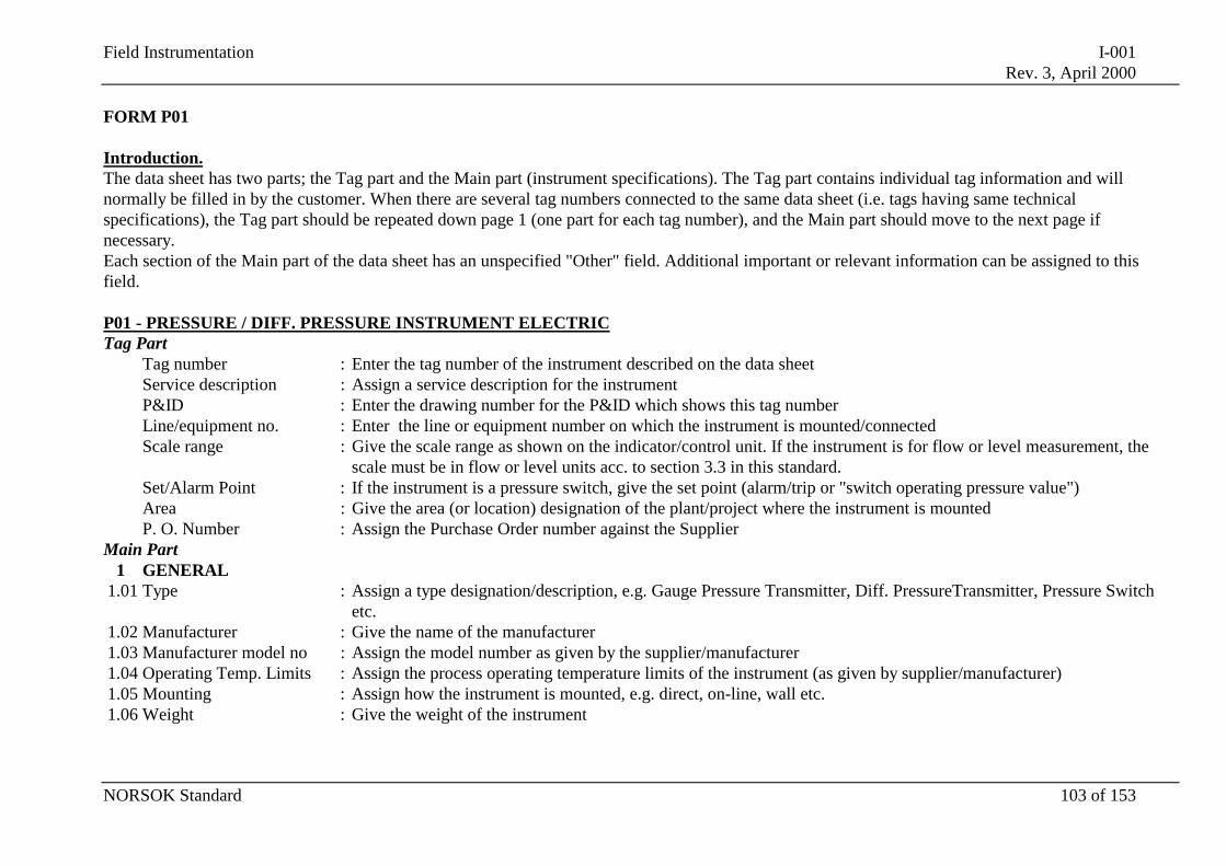
Field Instrumentation I-001Rev. 3, April 2000
NORSOK Standard 103 of 153
FORM P01
Introduction.The data sheet has two parts; the Tag part and the Main part (instrument specifications). The Tag part contains individual tag information and willnormally be filled in by the customer. When there are several tag numbers connected to the same data sheet (i.e. tags having same technicalspecifications), the Tag part should be repeated down page 1 (one part for each tag number), and the Main part should move to the next page ifnecessary.Each section of the Main part of the data sheet has an unspecified "Other" field. Additional important or relevant information can be assigned to thisfield.
P01 - PRESSURE / DIFF. PRESSURE INSTRUMENT ELECTRICTag Part
Tag number : Enter the tag number of the instrument described on the data sheetService description : Assign a service description for the instrumentP&ID : Enter the drawing number for the P&ID which shows this tag numberLine/equipment no. : Enter the line or equipment number on which the instrument is mounted/connectedScale range : Give the scale range as shown on the indicator/control unit. If the instrument is for flow or level measurement, the
scale must be in flow or level units acc. to section 3.3 in this standard.Set/Alarm Point : If the instrument is a pressure switch, give the set point (alarm/trip or "switch operating pressure value")Area : Give the area (or location) designation of the plant/project where the instrument is mountedP. O. Number : Assign the Purchase Order number against the Supplier
Main Part1 GENERAL
1.01 Type : Assign a type designation/description, e.g. Gauge Pressure Transmitter, Diff. PressureTransmitter, Pressure Switchetc.
1.02 Manufacturer : Give the name of the manufacturer1.03 Manufacturer model no : Assign the model number as given by the supplier/manufacturer1.04 Operating Temp. Limits : Assign the process operating temperature limits of the instrument (as given by supplier/manufacturer)1.05 Mounting : Assign how the instrument is mounted, e.g. direct, on-line, wall etc.1.06 Weight : Give the weight of the instrument
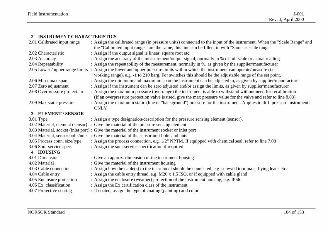
Field Instrumentation I-001Rev. 3, April 2000
NORSOK Standard 104 of 153
2 INSTRUMENT CHARACTERISTICS2.01 Calibrated input range : Assign the calibrated range (in pressure units) connected to the input of the instrument. When the "Scale Range" and
the "Calibrated input range" are the same, this line can be filled in with "Same as scale range"2.02 Characteristic : Assign if the output signal is linear, square root etc.2.03 Accuracy : Assign the accuracy of the measurement/output signal, normally in % of full scale or actual reading2.04 Repeatability : Assign the repeatability of the measurement, normally in %, as given by the supplier/manufacturer2.05 Lower / upper range limits : Assign the lower and upper pressure limits within which the instrument can operate/measure (i.e.
working range), e.g. -1 to 210 barg. For switches this should be the adjustable range of the set point.2.06 Min / max span : Assign the minimum and maximum span the instrument can be adjusted to, as given by supplier/manufacturer2.07 Zero adjustment : Assign if the instrument can be zero adjusted and/or assign the limits, as given by supplier/manufacturer2.08 Overpressure protect. to : Assign the maximum pressure (overrange) the instrument is able to withstand without need for recalibration
(If an overpressure protection valve is used, give the max pressure value for the valve and refer to line 8.03)2.09 Max static pressure : Assign the maximum static (line or "background") pressure for the instrument. Applies to diff. pressure instruments
ONLY3 ELEMENT / SENSOR
3.01 Type : Assign a type designation/description for the pressure sensing element (sensor),3.02 Material, element (sensor) : Give the material of the pressure sensing element3.03 Material, socket (inlet port) : Give the material of the instrument socket or inlet port3.04 Material, sensor bolts/nuts : Give the material of the sensor unit bolts and nuts3.05 Process conn. size/type : Assign the process connection, e.g. 1/2" NPTM. If equipped with chemical seal, refer to line 7.083.06 Sour service spec. : Assign the sour service specification if required
4 HOUSING4.01 Dimension : Give an approx. dimension of the instrument housing4.02 Material : Give the material of the instrument housing4.03 Cable connection : Assign how the cable(s) to the instrument should be connected, e.g. screwed terminals, flying leads etc.4.04 Cable entry : Assign the cable entry thread, e.g. M20 x 1,5 ISO, or if equipped with cable gland4.05 Enclosure protection : Assign the enclosure (weather) protection of the instrument housing, e.g. IP664.06 Ex. classification : Assign the Ex certification class of the instrument4.07 Protective coating : If coated, assign the type of coating (painting) and color
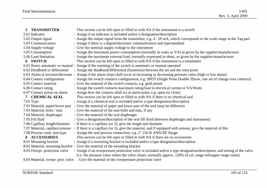
Field Instrumentation I-001Rev. 3, April 2000
NORSOK Standard 105 of 153
5 TRANSMITTER This section can be left open or filled in with NA if the instrument is a switch5.01 Indicator : Assign if an indicator is included and/or a designation/description5.02 Output signal : Assign the output signal from the transmitter, e.g. 4 - 20 mA, which corresponds to the scale range in the Tag part5.03 Communication : Assign if there is a digital/electronic communication and type/standard5.04 Supply voltage : Give the nominal supply voltage to the instrument5.05 Consumption : Assign the maximum power consumption (normally in watts or VA) as given by the supplier/manufacturer5.06 Load limitation : Assign the maximum external load, normally expressed in ohms, as given by the supplier/manufacturer
6 SWITCH This section can be left open or filled in with NA if the instrument is a transmitter6.01 Reset; automatic or manual : Assign if the resetting of the switch is automatic or manual operated6.02 Deadband or differential : Assign the deadband/differential (hysteresis) between the set and the reset point6.03 Alarm at increase/decrease : Assign if the alarm (trip) shall occur at increasing or decreasing pressure value (high or low alarm)6.04 Contact configuration : Assign the switch contacts configuration, e.g. SPDT (Single Point Double Throw, one set of change over contacts)6.05 Contact material : Give the material of the switch contacts, e.g. gold plated6.06 Contact rating : Assign the switch contacts maximum rating/load in electrical current or VA/Watts6.07 Contact action on alarm : Assign how the contacts shall act at alarm point, e.g. open (or close)
7 CHEMICAL SEAL This section can be left open or filled in with NA if there is no chemical seal7.01 Type : Assign if a chemical seal is included and/or a type designation/description7.01 Material, upper/lower part : Give the material of upper and lower part of the seal (may be different)7.03 Material, bolts / nuts : Give the material of the seal bolts and nuts, if any7.04 Material, diaphragm : Give the material of the seal diaphragm7.05 Fill fluid : Give a designation/description of the seal fill fluid (between diaphragm and instrument)7.06 Capillary length/diameter : If there is a capillary (or 2), give the length and diameter7.07 Material, capillary/armour : If there is a capillary (or 2), give the material, and if equipped with armour, give the material of this7.08 Process conn. size/type : Assign the seal process connection, e.g. 2" 150 lb ANSI RF flange
8 ACCESSORIES This section can be left open or filled in with NA if there are no accessories8.01 Mounting bracket : Assign if a mounting bracket is included and/or a type designation/description8.02 Material, mounting bracket : Give the material of the mounting bracket8.03 Overpr. protection valve : Assign if an overpressure protection valve is included and/or a type designation/description, and setting of the valve
(i.e. the pressure value where the valve closes, normally approx. 120% of cal. range end/upper range value)8.04 Material, overpr. prot. valve : Give the material of the overpressure protection valve
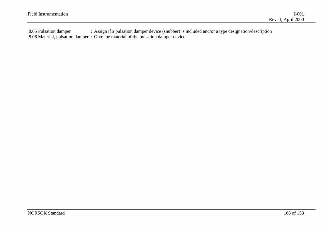
Field Instrumentation I-001Rev. 3, April 2000
NORSOK Standard 106 of 153
8.05 Pulsation damper : Assign if a pulsation damper device (snubber) is included and/or a type designation/description8.06 Material, pulsation damper : Give the material of the pulsation damper device
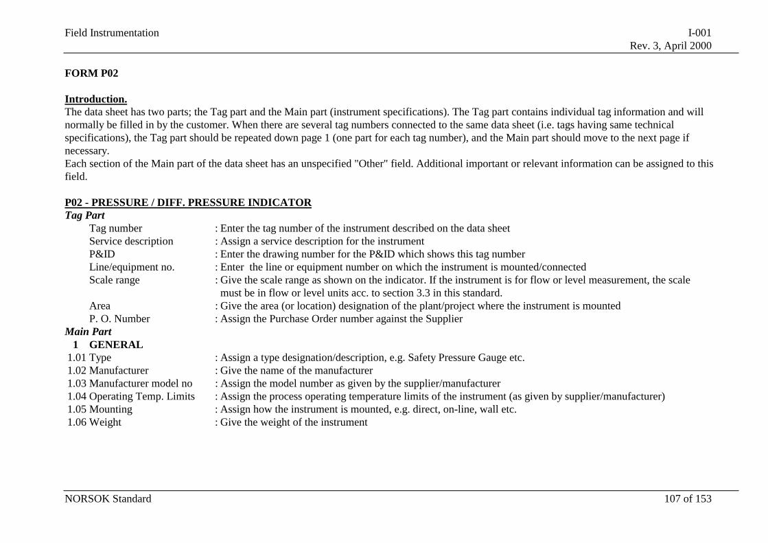
Field Instrumentation I-001Rev. 3, April 2000
NORSOK Standard 107 of 153
FORM P02
Introduction.The data sheet has two parts; the Tag part and the Main part (instrument specifications). The Tag part contains individual tag information and willnormally be filled in by the customer. When there are several tag numbers connected to the same data sheet (i.e. tags having same technicalspecifications), the Tag part should be repeated down page 1 (one part for each tag number), and the Main part should move to the next page ifnecessary.Each section of the Main part of the data sheet has an unspecified "Other" field. Additional important or relevant information can be assigned to thisfield.
P02 - PRESSURE / DIFF. PRESSURE INDICATORTag Part
Tag number : Enter the tag number of the instrument described on the data sheetService description : Assign a service description for the instrumentP&ID : Enter the drawing number for the P&ID which shows this tag numberLine/equipment no. : Enter the line or equipment number on which the instrument is mounted/connectedScale range : Give the scale range as shown on the indicator. If the instrument is for flow or level measurement, the scale
must be in flow or level units acc. to section 3.3 in this standard.Area : Give the area (or location) designation of the plant/project where the instrument is mountedP. O. Number : Assign the Purchase Order number against the Supplier
Main Part1 GENERAL
1.01 Type : Assign a type designation/description, e.g. Safety Pressure Gauge etc.1.02 Manufacturer : Give the name of the manufacturer1.03 Manufacturer model no : Assign the model number as given by the supplier/manufacturer1.04 Operating Temp. Limits : Assign the process operating temperature limits of the instrument (as given by supplier/manufacturer)1.05 Mounting : Assign how the instrument is mounted, e.g. direct, on-line, wall etc.1.06 Weight : Give the weight of the instrument
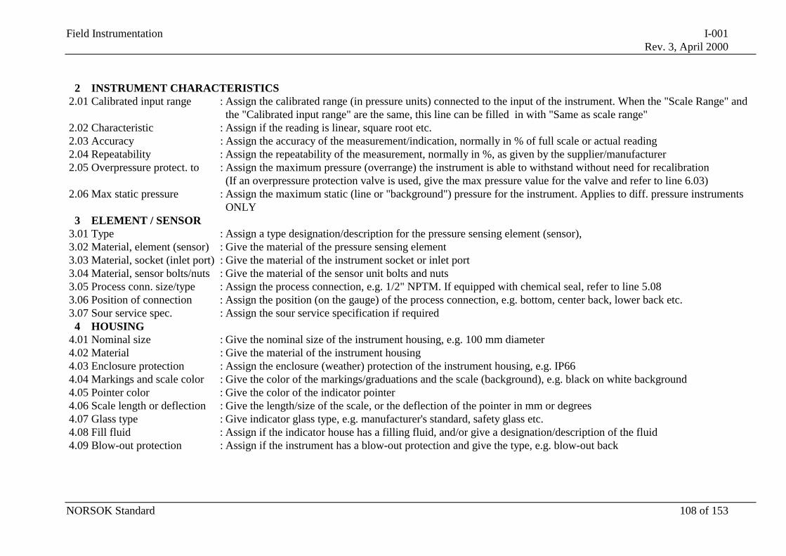
Field Instrumentation I-001Rev. 3, April 2000
NORSOK Standard 108 of 153
2 INSTRUMENT CHARACTERISTICS2.01 Calibrated input range : Assign the calibrated range (in pressure units) connected to the input of the instrument. When the "Scale Range" and
the "Calibrated input range" are the same, this line can be filled in with "Same as scale range"2.02 Characteristic : Assign if the reading is linear, square root etc.2.03 Accuracy : Assign the accuracy of the measurement/indication, normally in % of full scale or actual reading2.04 Repeatability : Assign the repeatability of the measurement, normally in %, as given by the supplier/manufacturer2.05 Overpressure protect. to : Assign the maximum pressure (overrange) the instrument is able to withstand without need for recalibration
(If an overpressure protection valve is used, give the max pressure value for the valve and refer to line 6.03)2.06 Max static pressure : Assign the maximum static (line or "background") pressure for the instrument. Applies to diff. pressure instruments
ONLY3 ELEMENT / SENSOR
3.01 Type : Assign a type designation/description for the pressure sensing element (sensor),3.02 Material, element (sensor) : Give the material of the pressure sensing element3.03 Material, socket (inlet port) : Give the material of the instrument socket or inlet port3.04 Material, sensor bolts/nuts : Give the material of the sensor unit bolts and nuts3.05 Process conn. size/type : Assign the process connection, e.g. 1/2" NPTM. If equipped with chemical seal, refer to line 5.083.06 Position of connection : Assign the position (on the gauge) of the process connection, e.g. bottom, center back, lower back etc.3.07 Sour service spec. : Assign the sour service specification if required
4 HOUSING4.01 Nominal size : Give the nominal size of the instrument housing, e.g. 100 mm diameter4.02 Material : Give the material of the instrument housing4.03 Enclosure protection : Assign the enclosure (weather) protection of the instrument housing, e.g. IP664.04 Markings and scale color : Give the color of the markings/graduations and the scale (background), e.g. black on white background4.05 Pointer color : Give the color of the indicator pointer4.06 Scale length or deflection : Give the length/size of the scale, or the deflection of the pointer in mm or degrees4.07 Glass type : Give indicator glass type, e.g. manufacturer's standard, safety glass etc.4.08 Fill fluid : Assign if the indicator house has a filling fluid, and/or give a designation/description of the fluid4.09 Blow-out protection : Assign if the instrument has a blow-out protection and give the type, e.g. blow-out back
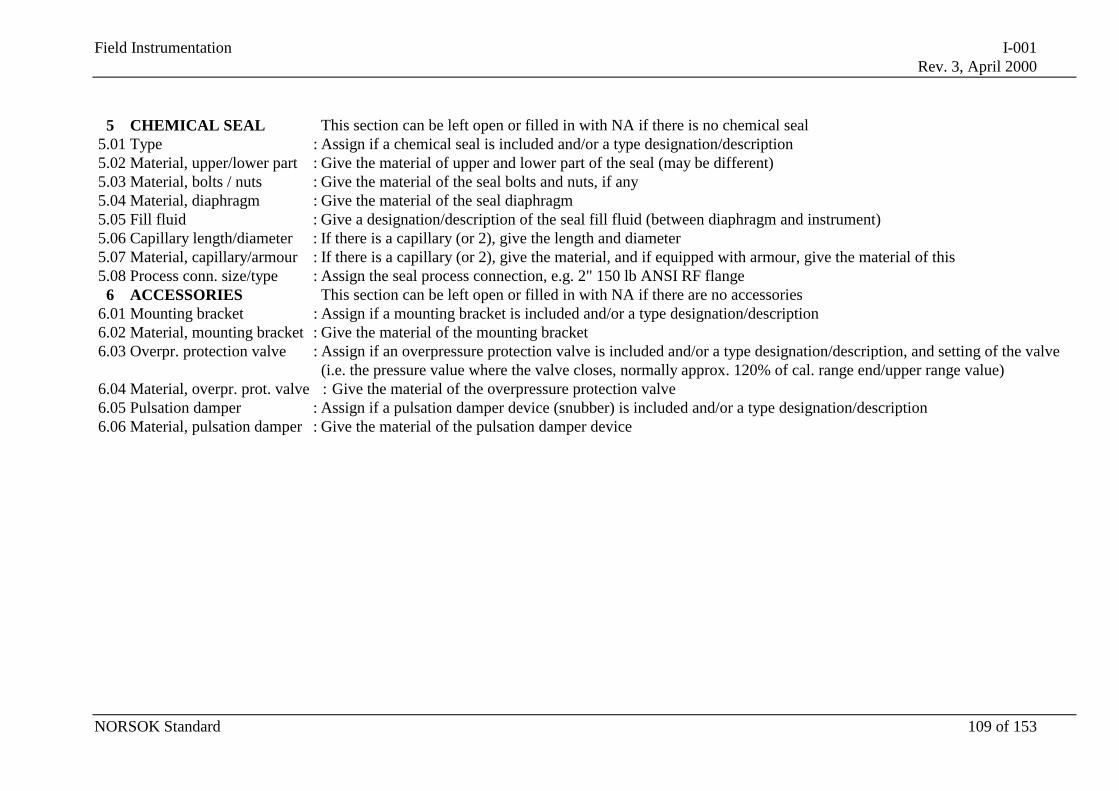
Field Instrumentation I-001Rev. 3, April 2000
NORSOK Standard 109 of 153
5 CHEMICAL SEAL This section can be left open or filled in with NA if there is no chemical seal5.01 Type : Assign if a chemical seal is included and/or a type designation/description5.02 Material, upper/lower part : Give the material of upper and lower part of the seal (may be different)5.03 Material, bolts / nuts : Give the material of the seal bolts and nuts, if any5.04 Material, diaphragm : Give the material of the seal diaphragm5.05 Fill fluid : Give a designation/description of the seal fill fluid (between diaphragm and instrument)5.06 Capillary length/diameter : If there is a capillary (or 2), give the length and diameter5.07 Material, capillary/armour : If there is a capillary (or 2), give the material, and if equipped with armour, give the material of this5.08 Process conn. size/type : Assign the seal process connection, e.g. 2" 150 lb ANSI RF flange
6 ACCESSORIES This section can be left open or filled in with NA if there are no accessories6.01 Mounting bracket : Assign if a mounting bracket is included and/or a type designation/description6.02 Material, mounting bracket : Give the material of the mounting bracket6.03 Overpr. protection valve : Assign if an overpressure protection valve is included and/or a type designation/description, and setting of the valve
(i.e. the pressure value where the valve closes, normally approx. 120% of cal. range end/upper range value)6.04 Material, overpr. prot. valve : Give the material of the overpressure protection valve6.05 Pulsation damper : Assign if a pulsation damper device (snubber) is included and/or a type designation/description6.06 Material, pulsation damper : Give the material of the pulsation damper device
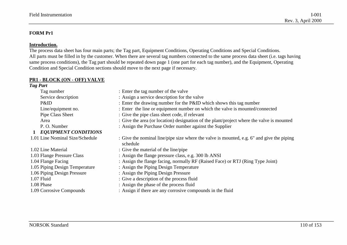
Field Instrumentation I-001Rev. 3, April 2000
NORSOK Standard 110 of 153
FORM Pr1
Introduction.The process data sheet has four main parts; the Tag part, Equipment Conditions, Operating Conditions and Special Conditions.All parts must be filled in by the customer. When there are several tag numbers connected to the same process data sheet (i.e. tags havingsame process conditions), the Tag part should be repeated down page 1 (one part for each tag number), and the Equipment, OperatingCondition and Special Condition sections should move to the next page if necessary.
PR1 - BLOCK (ON - OFF) VALVETag Part
Tag number : Enter the tag number of the valveService description : Assign a service description for the valveP&ID : Enter the drawing number for the P&ID which shows this tag numberLine/equipment no. : Enter the line or equipment number on which the valve is mounted/connectedPipe Class Sheet : Give the pipe class sheet code, if relevantArea : Give the area (or location) designation of the plant/project where the valve is mountedP. O. Number : Assign the Purchase Order number against the Supplier
1 EQUIPMENT CONDITIONS1.01 Line Nominal Size/Schedule : Give the nominal line/pipe size where the valve is mounted, e.g. 6" and give the piping
schedule1.02 Line Material : Give the material of the line/pipe1.03 Flange Pressure Class : Assign the flange pressure class, e.g. 300 lb ANSI1.04 Flange Facing : Assign the flange facing, normally RF (Raised Face) or RTJ (Ring Type Joint)1.05 Piping Design Temperature : Assign the Piping Design Temperature1.06 Piping Design Pressure : Assign the Piping Design Pressure1.07 Fluid : Give a description of the process fluid1.08 Phase : Assign the phase of the process fluid1.09 Corrosive Compounds : Assign if there are any corrosive compounds in the fluid
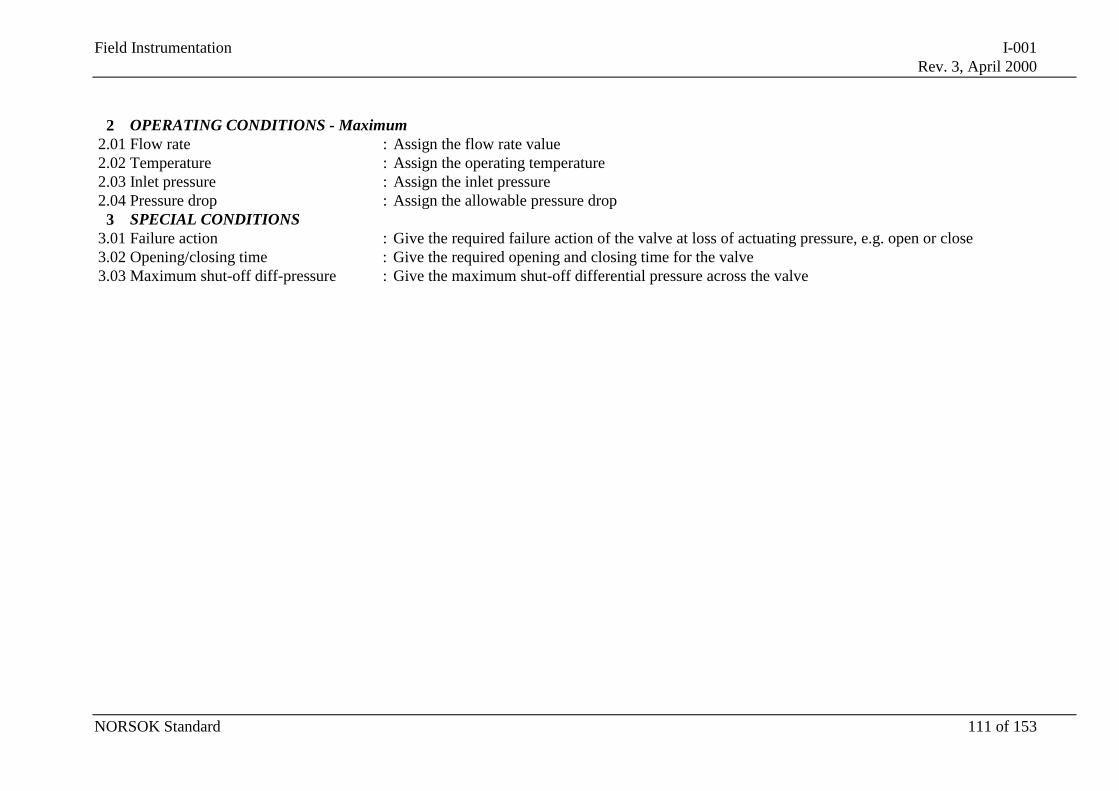
Field Instrumentation I-001Rev. 3, April 2000
NORSOK Standard 111 of 153
2 OPERATING CONDITIONS - Maximum2.01 Flow rate : Assign the flow rate value2.02 Temperature : Assign the operating temperature2.03 Inlet pressure : Assign the inlet pressure2.04 Pressure drop : Assign the allowable pressure drop
3 SPECIAL CONDITIONS3.01 Failure action : Give the required failure action of the valve at loss of actuating pressure, e.g. open or close3.02 Opening/closing time : Give the required opening and closing time for the valve3.03 Maximum shut-off diff-pressure : Give the maximum shut-off differential pressure across the valve
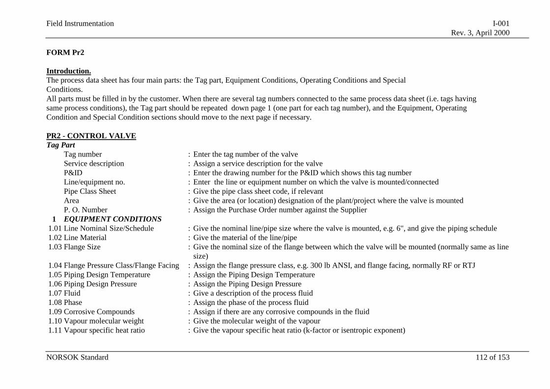
Field Instrumentation I-001Rev. 3, April 2000
NORSOK Standard 112 of 153
FORM Pr2
Introduction.The process data sheet has four main parts: the Tag part, Equipment Conditions, Operating Conditions and SpecialConditions.All parts must be filled in by the customer. When there are several tag numbers connected to the same process data sheet (i.e. tags havingsame process conditions), the Tag part should be repeated down page 1 (one part for each tag number), and the Equipment, OperatingCondition and Special Condition sections should move to the next page if necessary.
PR2 - CONTROL VALVETag Part
Tag number : Enter the tag number of the valveService description : Assign a service description for the valveP&ID : Enter the drawing number for the P&ID which shows this tag numberLine/equipment no. : Enter the line or equipment number on which the valve is mounted/connectedPipe Class Sheet : Give the pipe class sheet code, if relevantArea : Give the area (or location) designation of the plant/project where the valve is mountedP. O. Number : Assign the Purchase Order number against the Supplier
1 EQUIPMENT CONDITIONS1.01 Line Nominal Size/Schedule : Give the nominal line/pipe size where the valve is mounted, e.g. 6", and give the piping schedule1.02 Line Material : Give the material of the line/pipe1.03 Flange Size : Give the nominal size of the flange between which the valve will be mounted (normally same as line
size)1.04 Flange Pressure Class/Flange Facing : Assign the flange pressure class, e.g. 300 lb ANSI, and flange facing, normally RF or RTJ1.05 Piping Design Temperature : Assign the Piping Design Temperature1.06 Piping Design Pressure : Assign the Piping Design Pressure1.07 Fluid : Give a description of the process fluid1.08 Phase : Assign the phase of the process fluid1.09 Corrosive Compounds : Assign if there are any corrosive compounds in the fluid1.10 Vapour molecular weight : Give the molecular weight of the vapour1.11 Vapour specific heat ratio : Give the vapour specific heat ratio (k-factor or isentropic exponent)
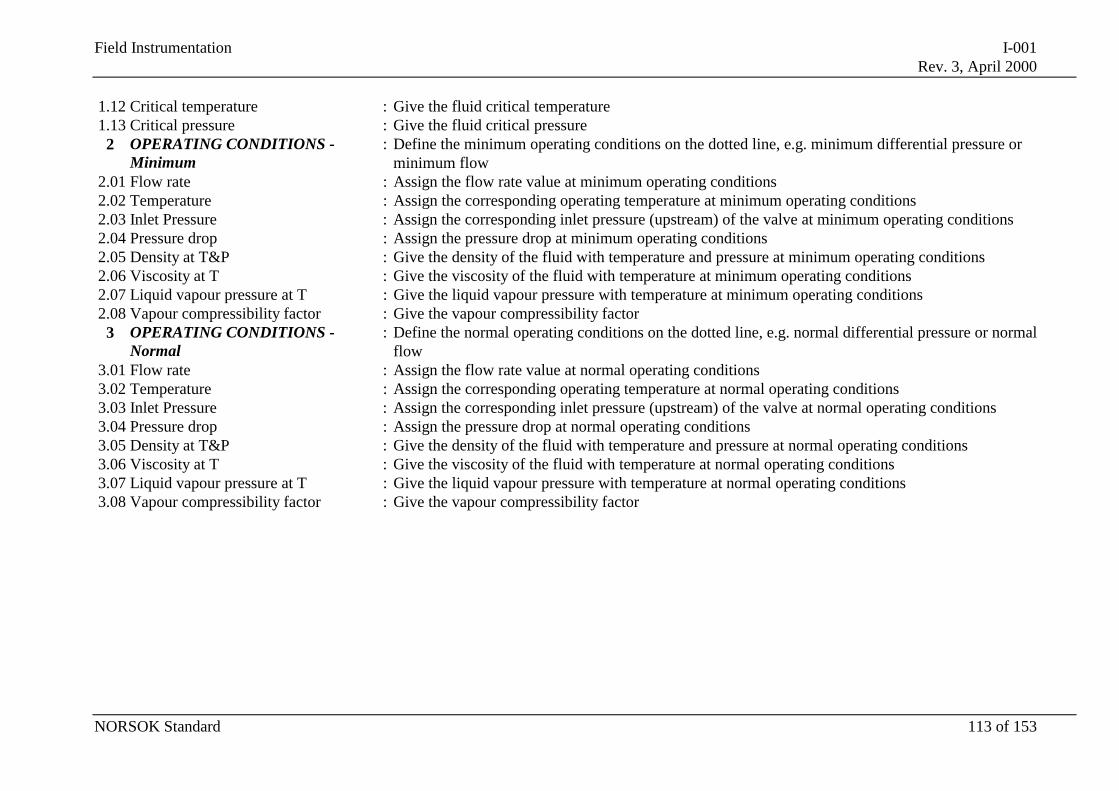
Field Instrumentation I-001Rev. 3, April 2000
NORSOK Standard 113 of 153
1.12 Critical temperature : Give the fluid critical temperature1.13 Critical pressure : Give the fluid critical pressure
2 OPERATING CONDITIONS -Minimum
: Define the minimum operating conditions on the dotted line, e.g. minimum differential pressure orminimum flow
2.01 Flow rate : Assign the flow rate value at minimum operating conditions2.02 Temperature : Assign the corresponding operating temperature at minimum operating conditions2.03 Inlet Pressure : Assign the corresponding inlet pressure (upstream) of the valve at minimum operating conditions2.04 Pressure drop : Assign the pressure drop at minimum operating conditions2.05 Density at T&P : Give the density of the fluid with temperature and pressure at minimum operating conditions2.06 Viscosity at T : Give the viscosity of the fluid with temperature at minimum operating conditions2.07 Liquid vapour pressure at T : Give the liquid vapour pressure with temperature at minimum operating conditions2.08 Vapour compressibility factor : Give the vapour compressibility factor
3 OPERATING CONDITIONS -Normal
: Define the normal operating conditions on the dotted line, e.g. normal differential pressure or normalflow
3.01 Flow rate : Assign the flow rate value at normal operating conditions3.02 Temperature : Assign the corresponding operating temperature at normal operating conditions3.03 Inlet Pressure : Assign the corresponding inlet pressure (upstream) of the valve at normal operating conditions3.04 Pressure drop : Assign the pressure drop at normal operating conditions3.05 Density at T&P : Give the density of the fluid with temperature and pressure at normal operating conditions3.06 Viscosity at T : Give the viscosity of the fluid with temperature at normal operating conditions3.07 Liquid vapour pressure at T : Give the liquid vapour pressure with temperature at normal operating conditions3.08 Vapour compressibility factor : Give the vapour compressibility factor
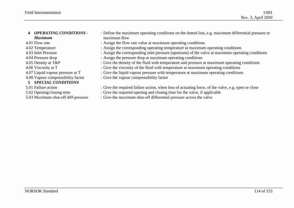
Field Instrumentation I-001Rev. 3, April 2000
NORSOK Standard 114 of 153
4 OPERATING CONDITIONS -Maximum
: Define the maximum operating conditions on the dotted line, e.g. maximum differential pressure ormaximum flow
4.01 Flow rate : Assign the flow rate value at maximum operating conditions4.02 Temperature : Assign the corresponding operating temperature at maximum operating conditions4.03 Inlet Pressure : Assign the corresponding inlet pressure (upstream) of the valve at maximum operating conditions4.04 Pressure drop : Assign the pressure drop at maximum operating conditions4.05 Density at T&P : Give the density of the fluid with temperature and pressure at maximum operating conditions4.06 Viscosity at T : Give the viscosity of the fluid with temperature at maximum operating conditions4.07 Liquid vapour pressure at T : Give the liquid vapour pressure with temperature at maximum operating conditions4.08 Vapour compressibility factor : Give the vapour compressibility factor
5 SPECIAL CONDITIONS5.01 Failure action : Give the required failure action, when loss of actuating force, of the valve, e.g. open or close5.02 Opening/closing time : Give the required opening and closing time for the valve, if applicable5.03 Maximum shut-off diff-pressure : Give the maximum shut-off differential pressure across the valve
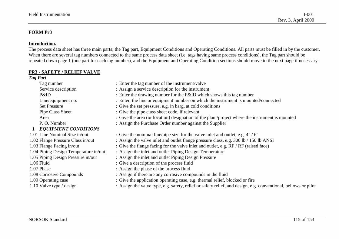
Field Instrumentation I-001Rev. 3, April 2000
NORSOK Standard 115 of 153
FORM Pr3
Introduction.The process data sheet has three main parts; the Tag part, Equipment Conditions and Operating Conditions. All parts must be filled in by the customer.When there are several tag numbers connected to the same process data sheet (i.e. tags having same process conditions), the Tag part should berepeated down page 1 (one part for each tag number), and the Equipment and Operating Condition sections should move to the next page if necessary.
PR3 - SAFETY / RELIEF VALVETag Part
Tag number : Enter the tag number of the instrument/valveService description : Assign a service description for the instrumentP&ID : Enter the drawing number for the P&ID which shows this tag numberLine/equipment no. : Enter the line or equipment number on which the instrument is mounted/connectedSet Pressure : Give the set pressure, e.g. in barg, at cold conditionsPipe Class Sheet : Give the pipe class sheet code, if relevantArea : Give the area (or location) designation of the plant/project where the instrument is mountedP. O. Number : Assign the Purchase Order number against the Supplier
1 EQUIPMENT CONDITIONS1.01 Line Nominal Size in/out : Give the nominal line/pipe size for the valve inlet and outlet, e.g. 4" / 6"1.02 Flange Pressure Class in/out : Assign the valve inlet and outlet flange pressure class, e.g. 300 lb / 150 lb ANSI1.03 Flange Facing in/out : Give the flange facing for the valve inlet and outlet, e.g. RF / RF (raised face)1.04 Piping Design Temperature in/out : Assign the inlet and outlet Piping Design Temperature1.05 Piping Design Pressure in/out : Assign the inlet and outlet Piping Design Pressure1.06 Fluid : Give a description of the process fluid1.07 Phase : Assign the phase of the process fluid1.08 Corrosive Compounds : Assign if there are any corrosive compounds in the fluid1.09 Operating case : Give the application operating case, e.g. thermal relief, blocked or fire1.10 Valve type / design : Assign the valve type, e.g. safety, relief or safety relief, and design, e.g. conventional, bellows or pilot
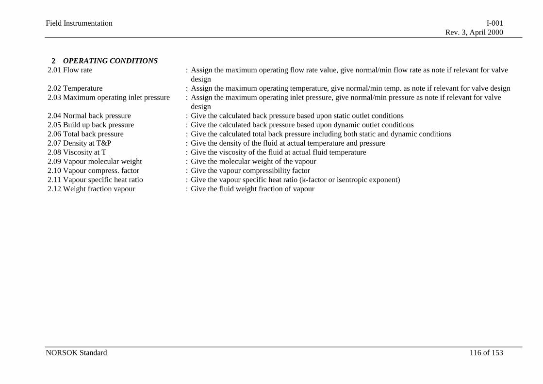
Field Instrumentation I-001Rev. 3, April 2000
NORSOK Standard 116 of 153
2 OPERATING CONDITIONS2.01 Flow rate : Assign the maximum operating flow rate value, give normal/min flow rate as note if relevant for valve
design2.02 Temperature : Assign the maximum operating temperature, give normal/min temp. as note if relevant for valve design2.03 Maximum operating inlet pressure : Assign the maximum operating inlet pressure, give normal/min pressure as note if relevant for valve
design2.04 Normal back pressure : Give the calculated back pressure based upon static outlet conditions2.05 Build up back pressure : Give the calculated back pressure based upon dynamic outlet conditions2.06 Total back pressure : Give the calculated total back pressure including both static and dynamic conditions2.07 Density at T&P : Give the density of the fluid at actual temperature and pressure2.08 Viscosity at T : Give the viscosity of the fluid at actual fluid temperature2.09 Vapour molecular weight : Give the molecular weight of the vapour2.10 Vapour compress. factor : Give the vapour compressibility factor2.11 Vapour specific heat ratio : Give the vapour specific heat ratio (k-factor or isentropic exponent)2.12 Weight fraction vapour : Give the fluid weight fraction of vapour
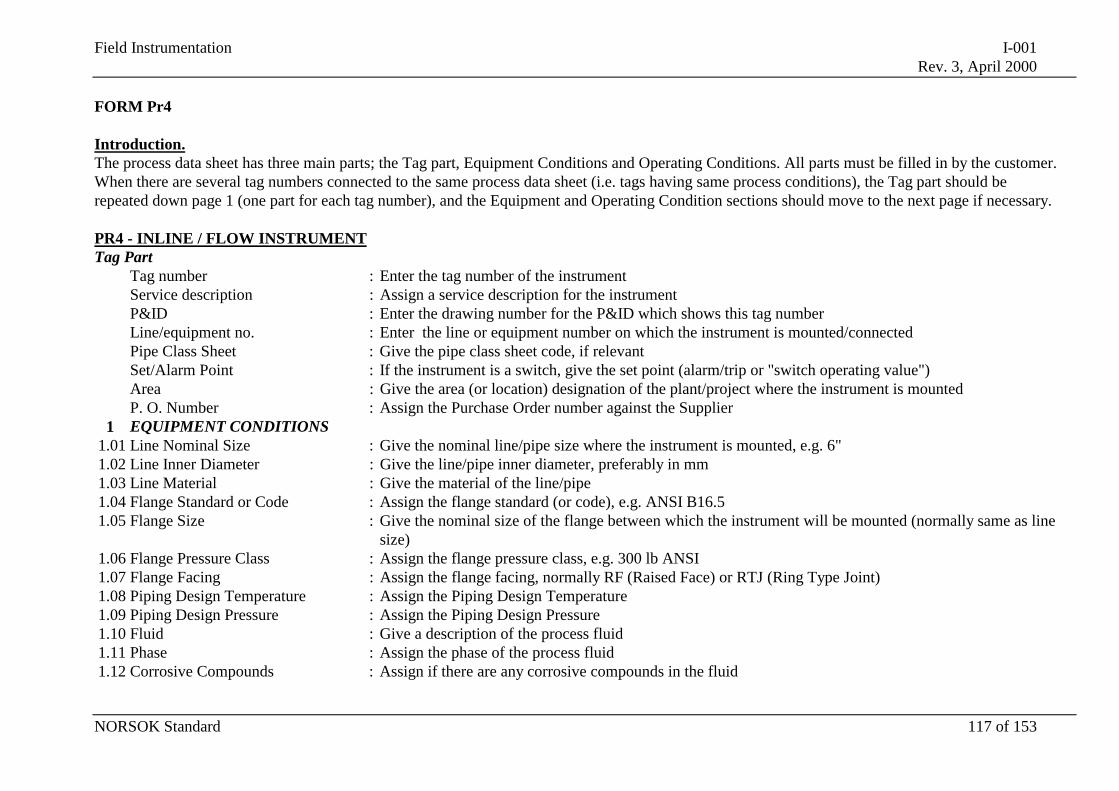
Field Instrumentation I-001Rev. 3, April 2000
NORSOK Standard 117 of 153
FORM Pr4
Introduction.The process data sheet has three main parts; the Tag part, Equipment Conditions and Operating Conditions. All parts must be filled in by the customer.When there are several tag numbers connected to the same process data sheet (i.e. tags having same process conditions), the Tag part should berepeated down page 1 (one part for each tag number), and the Equipment and Operating Condition sections should move to the next page if necessary.
PR4 - INLINE / FLOW INSTRUMENTTag Part
Tag number : Enter the tag number of the instrumentService description : Assign a service description for the instrumentP&ID : Enter the drawing number for the P&ID which shows this tag numberLine/equipment no. : Enter the line or equipment number on which the instrument is mounted/connectedPipe Class Sheet : Give the pipe class sheet code, if relevantSet/Alarm Point : If the instrument is a switch, give the set point (alarm/trip or "switch operating value")Area : Give the area (or location) designation of the plant/project where the instrument is mountedP. O. Number : Assign the Purchase Order number against the Supplier
1 EQUIPMENT CONDITIONS1.01 Line Nominal Size : Give the nominal line/pipe size where the instrument is mounted, e.g. 6"1.02 Line Inner Diameter : Give the line/pipe inner diameter, preferably in mm1.03 Line Material : Give the material of the line/pipe1.04 Flange Standard or Code : Assign the flange standard (or code), e.g. ANSI B16.51.05 Flange Size : Give the nominal size of the flange between which the instrument will be mounted (normally same as line
size)1.06 Flange Pressure Class : Assign the flange pressure class, e.g. 300 lb ANSI1.07 Flange Facing : Assign the flange facing, normally RF (Raised Face) or RTJ (Ring Type Joint)1.08 Piping Design Temperature : Assign the Piping Design Temperature1.09 Piping Design Pressure : Assign the Piping Design Pressure1.10 Fluid : Give a description of the process fluid1.11 Phase : Assign the phase of the process fluid1.12 Corrosive Compounds : Assign if there are any corrosive compounds in the fluid
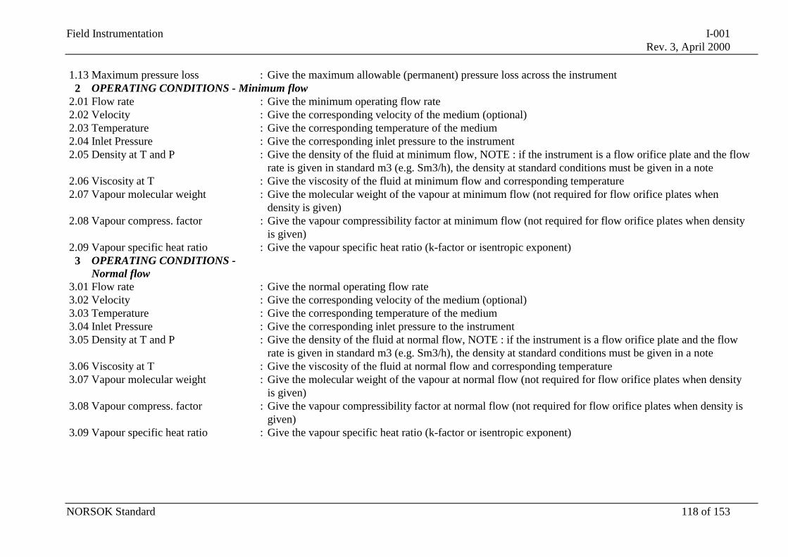
Field Instrumentation I-001Rev. 3, April 2000
NORSOK Standard 118 of 153
1.13 Maximum pressure loss : Give the maximum allowable (permanent) pressure loss across the instrument2 OPERATING CONDITIONS - Minimum flow
2.01 Flow rate : Give the minimum operating flow rate2.02 Velocity : Give the corresponding velocity of the medium (optional)2.03 Temperature : Give the corresponding temperature of the medium2.04 Inlet Pressure : Give the corresponding inlet pressure to the instrument2.05 Density at T and P : Give the density of the fluid at minimum flow, NOTE : if the instrument is a flow orifice plate and the flow
rate is given in standard m3 (e.g. Sm3/h), the density at standard conditions must be given in a note2.06 Viscosity at T : Give the viscosity of the fluid at minimum flow and corresponding temperature2.07 Vapour molecular weight : Give the molecular weight of the vapour at minimum flow (not required for flow orifice plates when
density is given)2.08 Vapour compress. factor : Give the vapour compressibility factor at minimum flow (not required for flow orifice plates when density
is given)2.09 Vapour specific heat ratio : Give the vapour specific heat ratio (k-factor or isentropic exponent)
3 OPERATING CONDITIONS -Normal flow
3.01 Flow rate : Give the normal operating flow rate3.02 Velocity : Give the corresponding velocity of the medium (optional)3.03 Temperature : Give the corresponding temperature of the medium3.04 Inlet Pressure : Give the corresponding inlet pressure to the instrument3.05 Density at T and P : Give the density of the fluid at normal flow, NOTE : if the instrument is a flow orifice plate and the flow
rate is given in standard m3 (e.g. Sm3/h), the density at standard conditions must be given in a note3.06 Viscosity at T : Give the viscosity of the fluid at normal flow and corresponding temperature3.07 Vapour molecular weight : Give the molecular weight of the vapour at normal flow (not required for flow orifice plates when density
is given)3.08 Vapour compress. factor : Give the vapour compressibility factor at normal flow (not required for flow orifice plates when density is
given)3.09 Vapour specific heat ratio : Give the vapour specific heat ratio (k-factor or isentropic exponent)
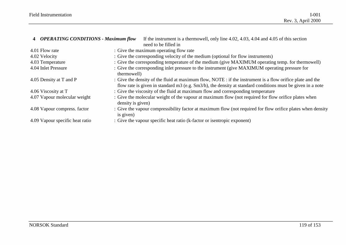
Field Instrumentation I-001Rev. 3, April 2000
NORSOK Standard 119 of 153
4 OPERATING CONDITIONS - Maximum flow If the instrument is a thermowell, only line 4.02, 4.03, 4.04 and 4.05 of this sectionneed to be filled in
4.01 Flow rate : Give the maximum operating flow rate4.02 Velocity : Give the corresponding velocity of the medium (optional for flow instruments)4.03 Temperature : Give the corresponding temperature of the medium (give MAXIMUM operating temp. for thermowell)4.04 Inlet Pressure : Give the corresponding inlet pressure to the instrument (give MAXIMUM operating pressure for
thermowell)4.05 Density at T and P : Give the density of the fluid at maximum flow, NOTE : if the instrument is a flow orifice plate and the
flow rate is given in standard m3 (e.g. Sm3/h), the density at standard conditions must be given in a note4.06 Viscosity at T : Give the viscosity of the fluid at maximum flow and corresponding temperature4.07 Vapour molecular weight : Give the molecular weight of the vapour at maximum flow (not required for flow orifice plates when
density is given)4.08 Vapour compress. factor : Give the vapour compressibility factor at maximum flow (not required for flow orifice plates when density
is given)4.09 Vapour specific heat ratio : Give the vapour specific heat ratio (k-factor or isentropic exponent)
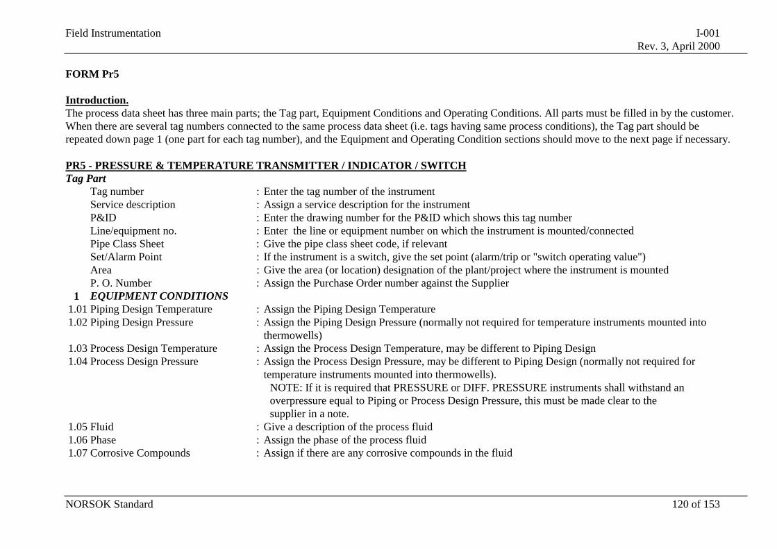
Field Instrumentation I-001Rev. 3, April 2000
NORSOK Standard 120 of 153
FORM Pr5
Introduction.The process data sheet has three main parts; the Tag part, Equipment Conditions and Operating Conditions. All parts must be filled in by the customer.When there are several tag numbers connected to the same process data sheet (i.e. tags having same process conditions), the Tag part should berepeated down page 1 (one part for each tag number), and the Equipment and Operating Condition sections should move to the next page if necessary.
PR5 - PRESSURE & TEMPERATURE TRANSMITTER / INDICATOR / SWITCHTag Part
Tag number : Enter the tag number of the instrumentService description : Assign a service description for the instrumentP&ID : Enter the drawing number for the P&ID which shows this tag numberLine/equipment no. : Enter the line or equipment number on which the instrument is mounted/connectedPipe Class Sheet : Give the pipe class sheet code, if relevantSet/Alarm Point : If the instrument is a switch, give the set point (alarm/trip or "switch operating value")Area : Give the area (or location) designation of the plant/project where the instrument is mountedP. O. Number : Assign the Purchase Order number against the Supplier
1 EQUIPMENT CONDITIONS1.01 Piping Design Temperature : Assign the Piping Design Temperature1.02 Piping Design Pressure : Assign the Piping Design Pressure (normally not required for temperature instruments mounted into
thermowells)1.03 Process Design Temperature : Assign the Process Design Temperature, may be different to Piping Design1.04 Process Design Pressure : Assign the Process Design Pressure, may be different to Piping Design (normally not required for
temperature instruments mounted into thermowells).NOTE: If it is required that PRESSURE or DIFF. PRESSURE instruments shall withstand anoverpressure equal to Piping or Process Design Pressure, this must be made clear to thesupplier in a note.
1.05 Fluid : Give a description of the process fluid1.06 Phase : Assign the phase of the process fluid1.07 Corrosive Compounds : Assign if there are any corrosive compounds in the fluid
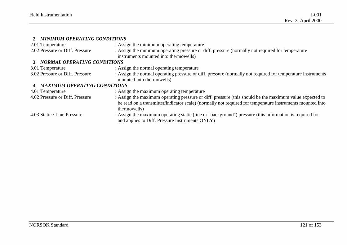
Field Instrumentation I-001Rev. 3, April 2000
NORSOK Standard 121 of 153
2 MINIMUM OPERATING CONDITIONS2.01 Temperature : Assign the minimum operating temperature2.02 Pressure or Diff. Pressure : Assign the minimum operating pressure or diff. pressure (normally not required for temperature
instruments mounted into thermowells)3 NORMAL OPERATING CONDITIONS
3.01 Temperature : Assign the normal operating temperature3.02 Pressure or Diff. Pressure : Assign the normal operating pressure or diff. pressure (normally not required for temperature instruments
mounted into thermowells)4 MAXIMUM OPERATING CONDITIONS
4.01 Temperature : Assign the maximum operating temperature4.02 Pressure or Diff. Pressure : Assign the maximum operating pressure or diff. pressure (this should be the maximum value expected to
be read on a transmitter/indicator scale) (normally not required for temperature instruments mounted intothermowells)
4.03 Static / Line Pressure : Assign the maximum operating static (line or "background") pressure (this information is required forand applies to Diff. Pressure Instruments ONLY)
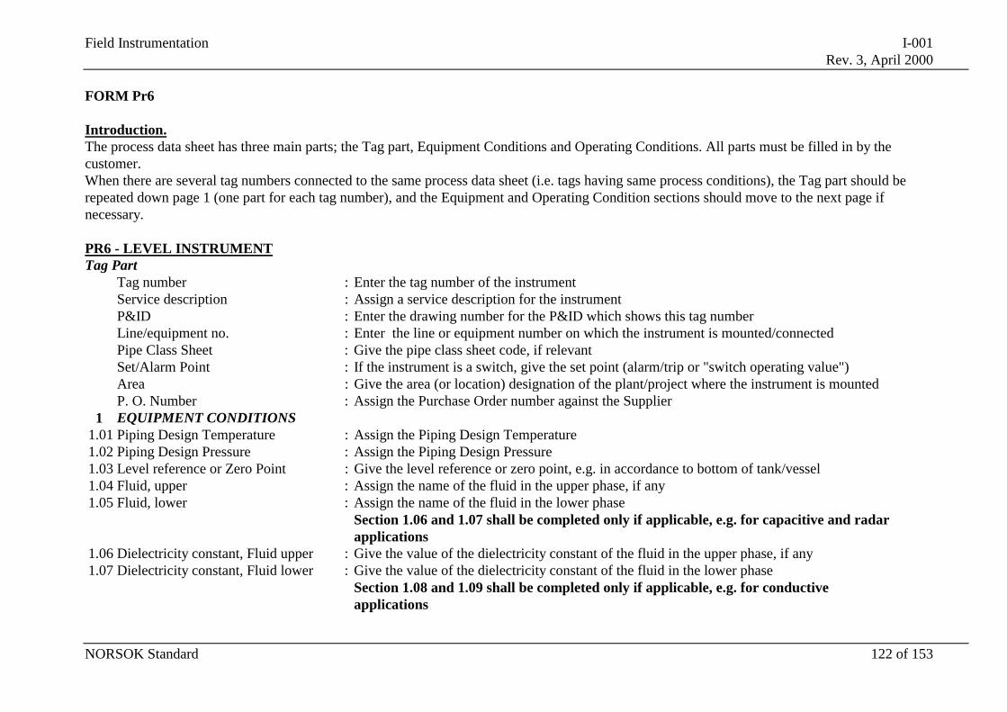
Field Instrumentation I-001Rev. 3, April 2000
NORSOK Standard 122 of 153
FORM Pr6
Introduction.The process data sheet has three main parts; the Tag part, Equipment Conditions and Operating Conditions. All parts must be filled in by thecustomer.When there are several tag numbers connected to the same process data sheet (i.e. tags having same process conditions), the Tag part should berepeated down page 1 (one part for each tag number), and the Equipment and Operating Condition sections should move to the next page ifnecessary.
PR6 - LEVEL INSTRUMENTTag Part
Tag number : Enter the tag number of the instrumentService description : Assign a service description for the instrumentP&ID : Enter the drawing number for the P&ID which shows this tag numberLine/equipment no. : Enter the line or equipment number on which the instrument is mounted/connectedPipe Class Sheet : Give the pipe class sheet code, if relevantSet/Alarm Point : If the instrument is a switch, give the set point (alarm/trip or "switch operating value")Area : Give the area (or location) designation of the plant/project where the instrument is mountedP. O. Number : Assign the Purchase Order number against the Supplier
1 EQUIPMENT CONDITIONS1.01 Piping Design Temperature : Assign the Piping Design Temperature1.02 Piping Design Pressure : Assign the Piping Design Pressure1.03 Level reference or Zero Point : Give the level reference or zero point, e.g. in accordance to bottom of tank/vessel1.04 Fluid, upper : Assign the name of the fluid in the upper phase, if any1.05 Fluid, lower : Assign the name of the fluid in the lower phase
Section 1.06 and 1.07 shall be completed only if applicable, e.g. for capacitive and radarapplications
1.06 Dielectricity constant, Fluid upper : Give the value of the dielectricity constant of the fluid in the upper phase, if any1.07 Dielectricity constant, Fluid lower : Give the value of the dielectricity constant of the fluid in the lower phase
Section 1.08 and 1.09 shall be completed only if applicable, e.g. for conductiveapplications
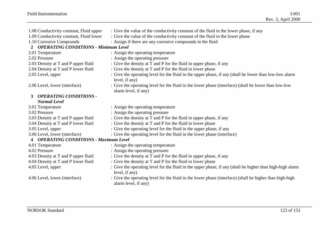
Field Instrumentation I-001Rev. 3, April 2000
NORSOK Standard 123 of 153
1.08 Conductivity constant, Fluid upper : Give the value of the conductivity constant of the fluid in the lower phase, if any1.09 Conductivity constant, Fluid lower : Give the value of the conductivity constant of the fluid in the lower phase1.10 Corrosive Compounds : Assign if there are any corrosive compounds in the fluid
2 OPERATING CONDITIONS - Minimum Level2.01 Temperature : Assign the operating temperature2.02 Pressure : Assign the operating pressure2.03 Density at T and P upper fluid : Give the density at T and P for the fluid in upper phase, if any2.04 Density at T and P lower fluid : Give the density at T and P for the fluid in lower phase2.05 Level, upper : Give the operating level for the fluid in the upper phase, if any (shall be lower than low-low alarm
level, if any)2.06 Level, lower (interface) : Give the operating level for the fluid in the lower phase (interface) (shall be lower than low-low
alarm level, if any)3 OPERATING CONDITIONS -
Normal Level3.01 Temperature : Assign the operating temperature3.02 Pressure : Assign the operating pressure3.03 Density at T and P upper fluid : Give the density at T and P for the fluid in upper phase, if any3.04 Density at T and P lower fluid : Give the density at T and P for the fluid in lower phase3.05 Level, upper : Give the operating level for the fluid in the upper phase, if any3.06 Level, lower (interface) : Give the operating level for the fluid in the lower phase (interface)
4 OPERATING CONDITIONS - Maximum Level4.01 Temperature : Assign the operating temperature4.02 Pressure : Assign the operating pressure4.03 Density at T and P upper fluid : Give the density at T and P for the fluid in upper phase, if any4.04 Density at T and P lower fluid : Give the density at T and P for the fluid in lower phase4.05 Level, upper : Give the operating level for the fluid in the upper phase, if any (shall be higher than high-high alarm
level, if any)4.06 Level, lower (interface) : Give the operating level for the fluid in the lower phase (interface) (shall be higher than high-high
alarm level, if any)
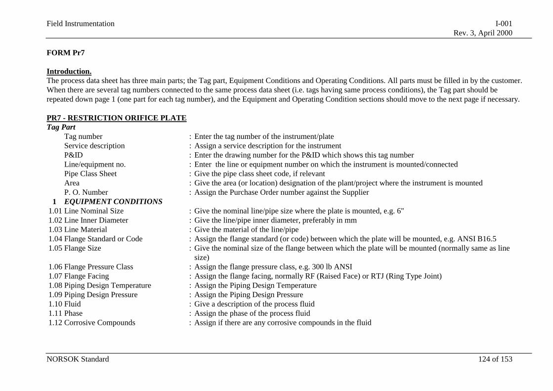
Field Instrumentation I-001Rev. 3, April 2000
NORSOK Standard 124 of 153
FORM Pr7
Introduction.The process data sheet has three main parts; the Tag part, Equipment Conditions and Operating Conditions. All parts must be filled in by the customer.When there are several tag numbers connected to the same process data sheet (i.e. tags having same process conditions), the Tag part should berepeated down page 1 (one part for each tag number), and the Equipment and Operating Condition sections should move to the next page if necessary.
PR7 - RESTRICTION ORIFICE PLATETag Part
Tag number : Enter the tag number of the instrument/plateService description : Assign a service description for the instrumentP&ID : Enter the drawing number for the P&ID which shows this tag numberLine/equipment no. : Enter the line or equipment number on which the instrument is mounted/connectedPipe Class Sheet : Give the pipe class sheet code, if relevantArea : Give the area (or location) designation of the plant/project where the instrument is mountedP. O. Number : Assign the Purchase Order number against the Supplier
1 EQUIPMENT CONDITIONS1.01 Line Nominal Size : Give the nominal line/pipe size where the plate is mounted, e.g. 6"1.02 Line Inner Diameter : Give the line/pipe inner diameter, preferably in mm1.03 Line Material : Give the material of the line/pipe1.04 Flange Standard or Code : Assign the flange standard (or code) between which the plate will be mounted, e.g. ANSI B16.51.05 Flange Size : Give the nominal size of the flange between which the plate will be mounted (normally same as line
size)1.06 Flange Pressure Class : Assign the flange pressure class, e.g. 300 lb ANSI1.07 Flange Facing : Assign the flange facing, normally RF (Raised Face) or RTJ (Ring Type Joint)1.08 Piping Design Temperature : Assign the Piping Design Temperature1.09 Piping Design Pressure : Assign the Piping Design Pressure1.10 Fluid : Give a description of the process fluid1.11 Phase : Assign the phase of the process fluid1.12 Corrosive Compounds : Assign if there are any corrosive compounds in the fluid
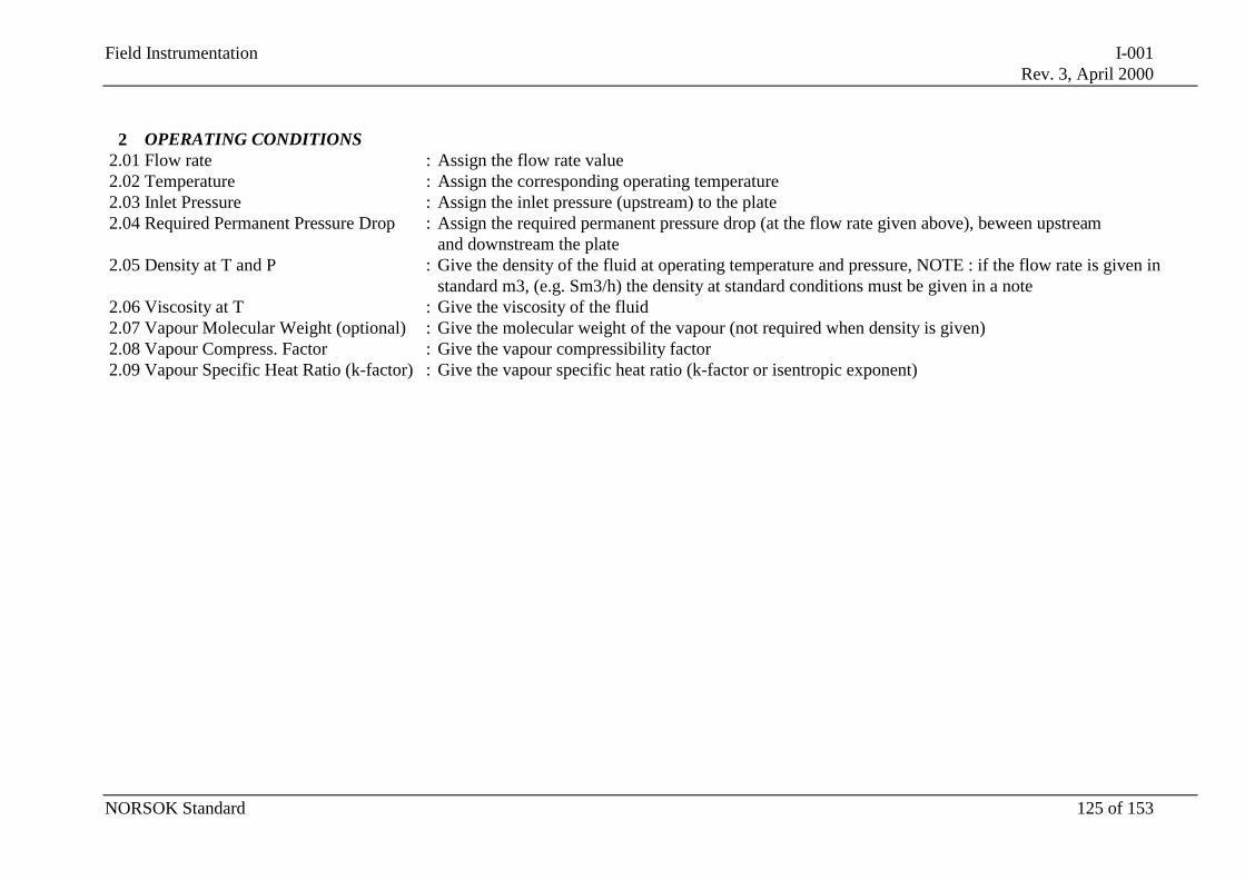
Field Instrumentation I-001Rev. 3, April 2000
NORSOK Standard 125 of 153
2 OPERATING CONDITIONS2.01 Flow rate : Assign the flow rate value2.02 Temperature : Assign the corresponding operating temperature2.03 Inlet Pressure : Assign the inlet pressure (upstream) to the plate2.04 Required Permanent Pressure Drop : Assign the required permanent pressure drop (at the flow rate given above), beween upstream
and downstream the plate2.05 Density at T and P : Give the density of the fluid at operating temperature and pressure, NOTE : if the flow rate is given in
standard m3, (e.g. Sm3/h) the density at standard conditions must be given in a note2.06 Viscosity at T : Give the viscosity of the fluid2.07 Vapour Molecular Weight (optional) : Give the molecular weight of the vapour (not required when density is given)2.08 Vapour Compress. Factor : Give the vapour compressibility factor2.09 Vapour Specific Heat Ratio (k-factor) : Give the vapour specific heat ratio (k-factor or isentropic exponent)
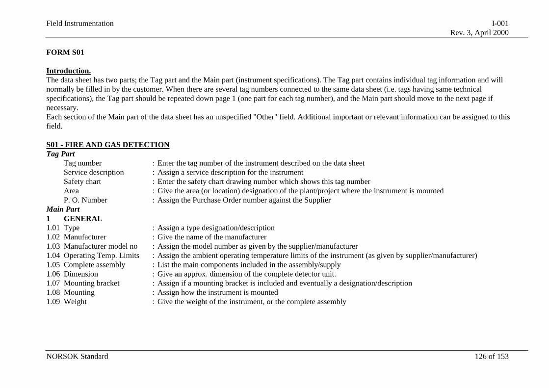
Field Instrumentation I-001Rev. 3, April 2000
NORSOK Standard 126 of 153
FORM S01
Introduction.The data sheet has two parts; the Tag part and the Main part (instrument specifications). The Tag part contains individual tag information and willnormally be filled in by the customer. When there are several tag numbers connected to the same data sheet (i.e. tags having same technicalspecifications), the Tag part should be repeated down page 1 (one part for each tag number), and the Main part should move to the next page ifnecessary.Each section of the Main part of the data sheet has an unspecified "Other" field. Additional important or relevant information can be assigned to thisfield.
S01 - FIRE AND GAS DETECTIONTag Part
Tag number : Enter the tag number of the instrument described on the data sheetService description : Assign a service description for the instrumentSafety chart : Enter the safety chart drawing number which shows this tag numberArea : Give the area (or location) designation of the plant/project where the instrument is mountedP. O. Number : Assign the Purchase Order number against the Supplier
Main Part1 GENERAL1.01 Type : Assign a type designation/description1.02 Manufacturer : Give the name of the manufacturer1.03 Manufacturer model no : Assign the model number as given by the supplier/manufacturer1.04 Operating Temp. Limits : Assign the ambient operating temperature limits of the instrument (as given by supplier/manufacturer)1.05 Complete assembly : List the main components included in the assembly/supply1.06 Dimension : Give an approx. dimension of the complete detector unit.1.07 Mounting bracket : Assign if a mounting bracket is included and eventually a designation/description1.08 Mounting : Assign how the instrument is mounted1.09 Weight : Give the weight of the instrument, or the complete assembly
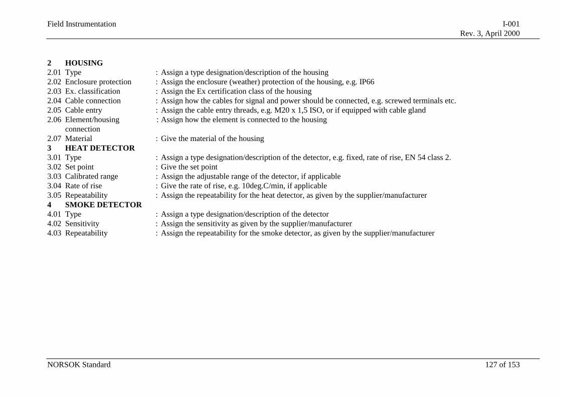
Field Instrumentation I-001Rev. 3, April 2000
NORSOK Standard 127 of 153
2 HOUSING2.01 Type : Assign a type designation/description of the housing2.02 Enclosure protection : Assign the enclosure (weather) protection of the housing, e.g. IP662.03 Ex. classification : Assign the Ex certification class of the housing2.04 Cable connection : Assign how the cables for signal and power should be connected, e.g. screwed terminals etc.2.05 Cable entry : Assign the cable entry threads, e.g. M20 x 1,5 ISO, or if equipped with cable gland2.06 Element/housing
connection: Assign how the element is connected to the housing
2.07 Material : Give the material of the housing3 HEAT DETECTOR3.01 Type : Assign a type designation/description of the detector, e.g. fixed, rate of rise, EN 54 class 2.3.02 Set point : Give the set point3.03 Calibrated range : Assign the adjustable range of the detector, if applicable3.04 Rate of rise : Give the rate of rise, e.g. 10deg.C/min, if applicable3.05 Repeatability : Assign the repeatability for the heat detector, as given by the supplier/manufacturer4 SMOKE DETECTOR4.01 Type : Assign a type designation/description of the detector4.02 Sensitivity : Assign the sensitivity as given by the supplier/manufacturer4.03 Repeatability : Assign the repeatability for the smoke detector, as given by the supplier/manufacturer
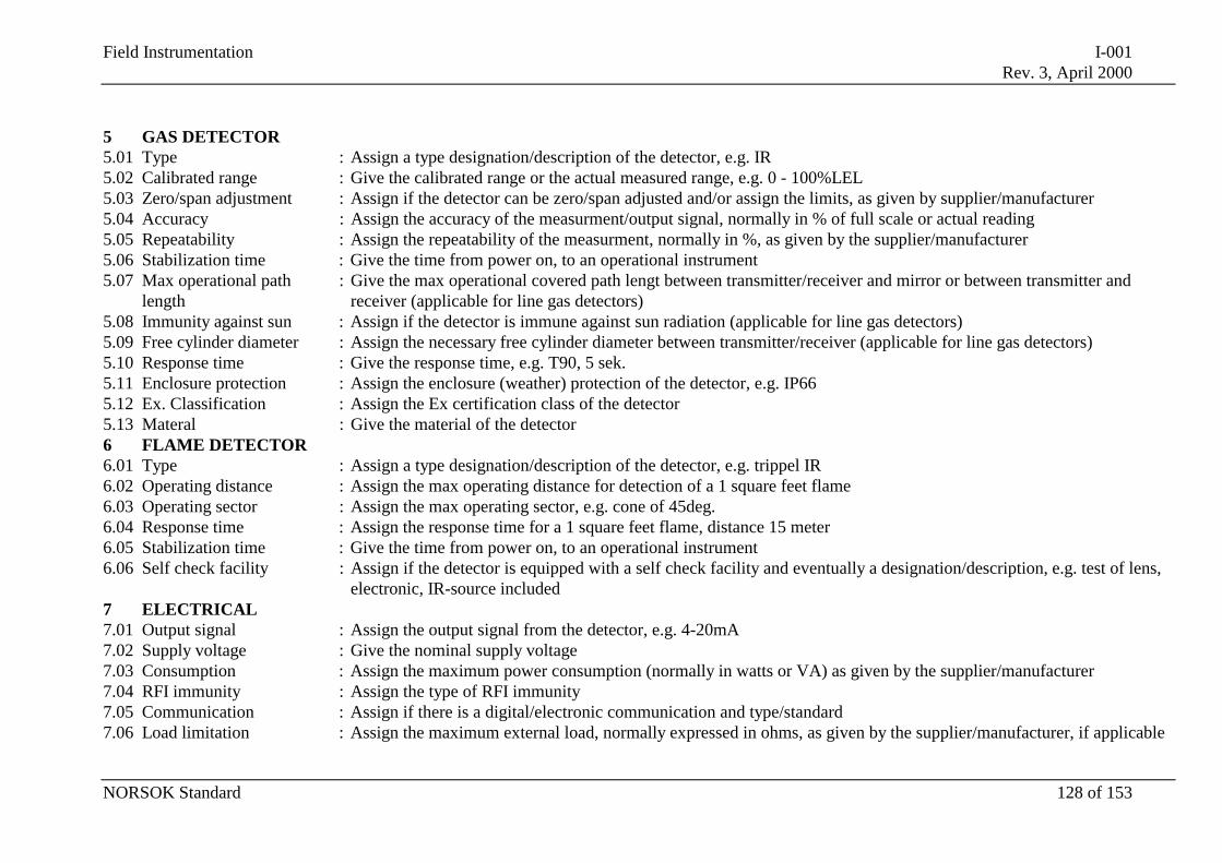
Field Instrumentation I-001Rev. 3, April 2000
NORSOK Standard 128 of 153
5 GAS DETECTOR5.01 Type : Assign a type designation/description of the detector, e.g. IR5.02 Calibrated range : Give the calibrated range or the actual measured range, e.g. 0 - 100%LEL5.03 Zero/span adjustment : Assign if the detector can be zero/span adjusted and/or assign the limits, as given by supplier/manufacturer5.04 Accuracy : Assign the accuracy of the measurment/output signal, normally in % of full scale or actual reading5.05 Repeatability : Assign the repeatability of the measurment, normally in %, as given by the supplier/manufacturer5.06 Stabilization time : Give the time from power on, to an operational instrument5.07 Max operational path
length: Give the max operational covered path lengt between transmitter/receiver and mirror or between transmitter and
receiver (applicable for line gas detectors)5.08 Immunity against sun : Assign if the detector is immune against sun radiation (applicable for line gas detectors)5.09 Free cylinder diameter : Assign the necessary free cylinder diameter between transmitter/receiver (applicable for line gas detectors)5.10 Response time : Give the response time, e.g. T90, 5 sek.5.11 Enclosure protection : Assign the enclosure (weather) protection of the detector, e.g. IP665.12 Ex. Classification : Assign the Ex certification class of the detector5.13 Materal : Give the material of the detector6 FLAME DETECTOR6.01 Type : Assign a type designation/description of the detector, e.g. trippel IR6.02 Operating distance : Assign the max operating distance for detection of a 1 square feet flame6.03 Operating sector : Assign the max operating sector, e.g. cone of 45deg.6.04 Response time : Assign the response time for a 1 square feet flame, distance 15 meter6.05 Stabilization time : Give the time from power on, to an operational instrument6.06 Self check facility : Assign if the detector is equipped with a self check facility and eventually a designation/description, e.g. test of lens,
electronic, IR-source included7 ELECTRICAL7.01 Output signal : Assign the output signal from the detector, e.g. 4-20mA7.02 Supply voltage : Give the nominal supply voltage7.03 Consumption : Assign the maximum power consumption (normally in watts or VA) as given by the supplier/manufacturer7.04 RFI immunity : Assign the type of RFI immunity7.05 Communication : Assign if there is a digital/electronic communication and type/standard7.06 Load limitation : Assign the maximum external load, normally expressed in ohms, as given by the supplier/manufacturer, if applicable
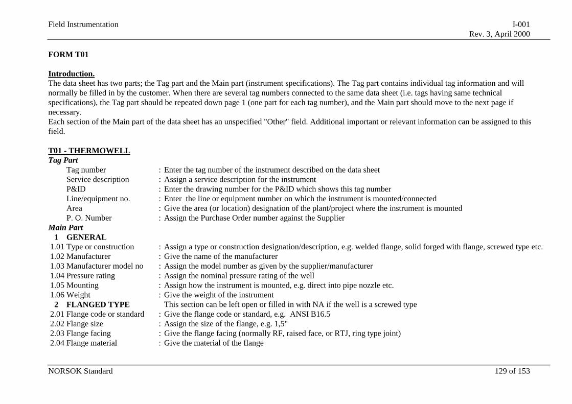
Field Instrumentation I-001Rev. 3, April 2000
NORSOK Standard 129 of 153
FORM T01
Introduction.The data sheet has two parts; the Tag part and the Main part (instrument specifications). The Tag part contains individual tag information and willnormally be filled in by the customer. When there are several tag numbers connected to the same data sheet (i.e. tags having same technicalspecifications), the Tag part should be repeated down page 1 (one part for each tag number), and the Main part should move to the next page ifnecessary.Each section of the Main part of the data sheet has an unspecified "Other" field. Additional important or relevant information can be assigned to thisfield.
T01 - THERMOWELLTag Part
Tag number : Enter the tag number of the instrument described on the data sheetService description : Assign a service description for the instrumentP&ID : Enter the drawing number for the P&ID which shows this tag numberLine/equipment no. : Enter the line or equipment number on which the instrument is mounted/connectedArea : Give the area (or location) designation of the plant/project where the instrument is mountedP. O. Number : Assign the Purchase Order number against the Supplier
Main Part1 GENERAL
1.01 Type or construction : Assign a type or construction designation/description, e.g. welded flange, solid forged with flange, screwed type etc.1.02 Manufacturer : Give the name of the manufacturer1.03 Manufacturer model no : Assign the model number as given by the supplier/manufacturer1.04 Pressure rating : Assign the nominal pressure rating of the well1.05 Mounting : Assign how the instrument is mounted, e.g. direct into pipe nozzle etc.1.06 Weight : Give the weight of the instrument
2 FLANGED TYPE This section can be left open or filled in with NA if the well is a screwed type2.01 Flange code or standard : Give the flange code or standard, e.g. ANSI B16.52.02 Flange size : Assign the size of the flange, e.g. 1,5"2.03 Flange facing : Give the flange facing (normally RF, raised face, or RTJ, ring type joint)2.04 Flange material : Give the material of the flange
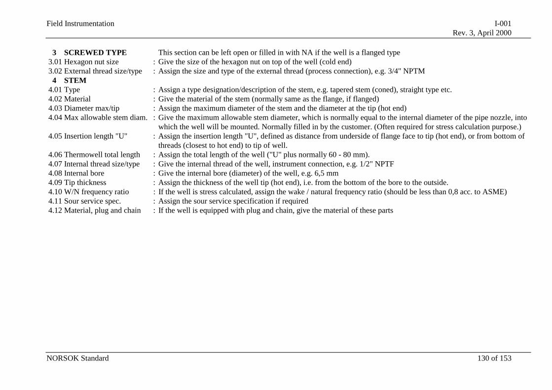
Field Instrumentation I-001Rev. 3, April 2000
NORSOK Standard 130 of 153
3 SCREWED TYPE This section can be left open or filled in with NA if the well is a flanged type3.01 Hexagon nut size : Give the size of the hexagon nut on top of the well (cold end)3.02 External thread size/type : Assign the size and type of the external thread (process connection), e.g. 3/4" NPTM
4 STEM4.01 Type : Assign a type designation/description of the stem, e.g. tapered stem (coned), straight type etc.4.02 Material : Give the material of the stem (normally same as the flange, if flanged)4.03 Diameter max/tip : Assign the maximum diameter of the stem and the diameter at the tip (hot end)4.04 Max allowable stem diam. : Give the maximum allowable stem diameter, which is normally equal to the internal diameter of the pipe nozzle, into
which the well will be mounted. Normally filled in by the customer. (Often required for stress calculation purpose.)4.05 Insertion length "U" : Assign the insertion length "U", defined as distance from underside of flange face to tip (hot end), or from bottom of
threads (closest to hot end) to tip of well.4.06 Thermowell total length : Assign the total length of the well ("U" plus normally 60 - 80 mm).4.07 Internal thread size/type : Give the internal thread of the well, instrument connection, e.g. 1/2" NPTF4.08 Internal bore : Give the internal bore (diameter) of the well, e.g. 6,5 mm4.09 Tip thickness : Assign the thickness of the well tip (hot end), i.e. from the bottom of the bore to the outside.4.10 W/N frequency ratio : If the well is stress calculated, assign the wake / natural frequency ratio (should be less than 0,8 acc. to ASME)4.11 Sour service spec. : Assign the sour service specification if required4.12 Material, plug and chain : If the well is equipped with plug and chain, give the material of these parts
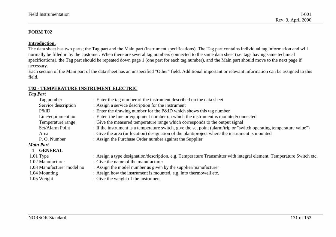
Field Instrumentation I-001Rev. 3, April 2000
NORSOK Standard 131 of 153
FORM T02
Introduction.The data sheet has two parts; the Tag part and the Main part (instrument specifications). The Tag part contains individual tag information and willnormally be filled in by the customer. When there are several tag numbers connected to the same data sheet (i.e. tags having same technicalspecifications), the Tag part should be repeated down page 1 (one part for each tag number), and the Main part should move to the next page ifnecessary.Each section of the Main part of the data sheet has an unspecified "Other" field. Additional important or relevant information can be assigned to thisfield.
T02 - TEMPERATURE INSTRUMENT ELECTRICTag Part
Tag number : Enter the tag number of the instrument described on the data sheetService description : Assign a service description for the instrumentP&ID : Enter the drawing number for the P&ID which shows this tag numberLine/equipment no. : Enter the line or equipment number on which the instrument is mounted/connectedTemperature range : Give the measured temperature range which corresponds to the output signalSet/Alarm Point : If the instrument is a temperature switch, give the set point (alarm/trip or "switch operating temperature value")Area : Give the area (or location) designation of the plant/project where the instrument is mountedP. O. Number : Assign the Purchase Order number against the Supplier
Main Part1 GENERAL
1.01 Type : Assign a type designation/description, e.g. Temperature Transmitter with integral element, Temperature Switch etc.1.02 Manufacturer : Give the name of the manufacturer1.03 Manufacturer model no : Assign the model number as given by the supplier/manufacturer1.04 Mounting : Assign how the instrument is mounted, e.g. into thermowell etc.1.05 Weight : Give the weight of the instrument
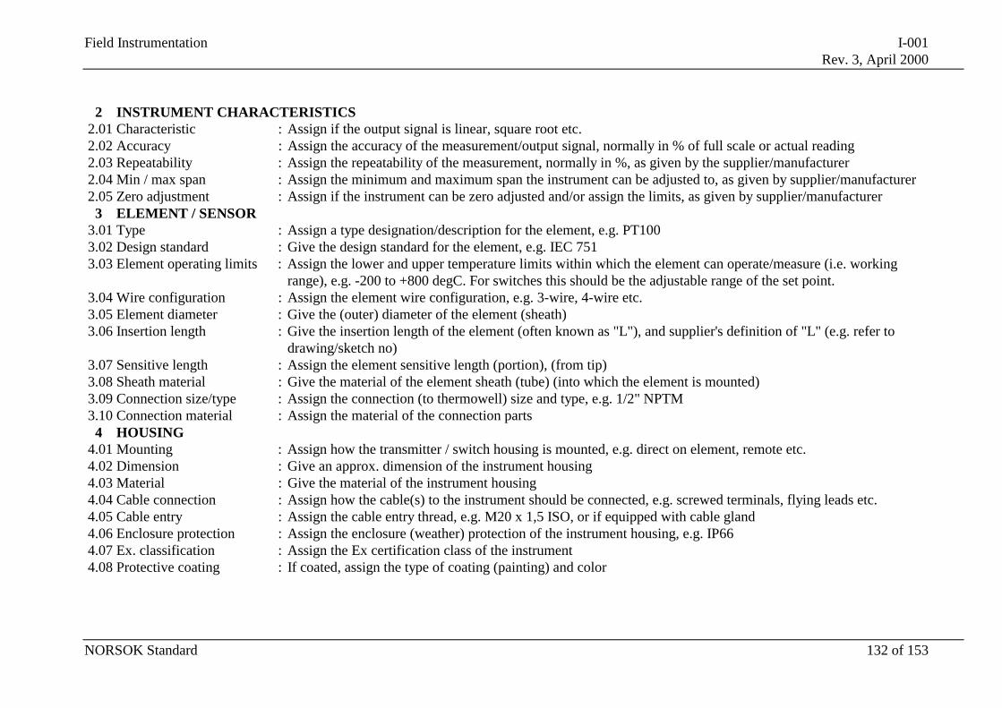
Field Instrumentation I-001Rev. 3, April 2000
NORSOK Standard 132 of 153
2 INSTRUMENT CHARACTERISTICS2.01 Characteristic : Assign if the output signal is linear, square root etc.2.02 Accuracy : Assign the accuracy of the measurement/output signal, normally in % of full scale or actual reading2.03 Repeatability : Assign the repeatability of the measurement, normally in %, as given by the supplier/manufacturer2.04 Min / max span : Assign the minimum and maximum span the instrument can be adjusted to, as given by supplier/manufacturer2.05 Zero adjustment : Assign if the instrument can be zero adjusted and/or assign the limits, as given by supplier/manufacturer
3 ELEMENT / SENSOR3.01 Type : Assign a type designation/description for the element, e.g. PT1003.02 Design standard : Give the design standard for the element, e.g. IEC 7513.03 Element operating limits : Assign the lower and upper temperature limits within which the element can operate/measure (i.e. working
range), e.g. -200 to +800 degC. For switches this should be the adjustable range of the set point.3.04 Wire configuration : Assign the element wire configuration, e.g. 3-wire, 4-wire etc.3.05 Element diameter : Give the (outer) diameter of the element (sheath)3.06 Insertion length : Give the insertion length of the element (often known as "L"), and supplier's definition of "L" (e.g. refer to
drawing/sketch no)3.07 Sensitive length : Assign the element sensitive length (portion), (from tip)3.08 Sheath material : Give the material of the element sheath (tube) (into which the element is mounted)3.09 Connection size/type : Assign the connection (to thermowell) size and type, e.g. 1/2" NPTM3.10 Connection material : Assign the material of the connection parts
4 HOUSING4.01 Mounting : Assign how the transmitter / switch housing is mounted, e.g. direct on element, remote etc.4.02 Dimension : Give an approx. dimension of the instrument housing4.03 Material : Give the material of the instrument housing4.04 Cable connection : Assign how the cable(s) to the instrument should be connected, e.g. screwed terminals, flying leads etc.4.05 Cable entry : Assign the cable entry thread, e.g. M20 x 1,5 ISO, or if equipped with cable gland4.06 Enclosure protection : Assign the enclosure (weather) protection of the instrument housing, e.g. IP664.07 Ex. classification : Assign the Ex certification class of the instrument4.08 Protective coating : If coated, assign the type of coating (painting) and color
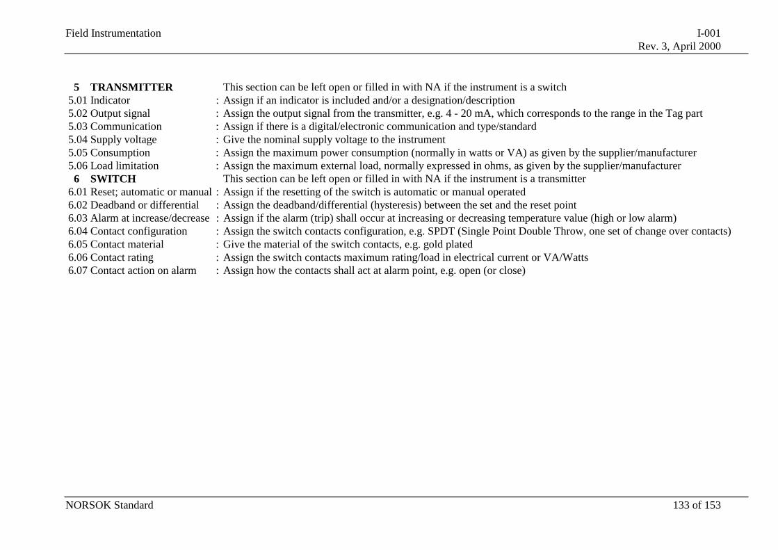
Field Instrumentation I-001Rev. 3, April 2000
NORSOK Standard 133 of 153
5 TRANSMITTER This section can be left open or filled in with NA if the instrument is a switch5.01 Indicator : Assign if an indicator is included and/or a designation/description5.02 Output signal : Assign the output signal from the transmitter, e.g. 4 - 20 mA, which corresponds to the range in the Tag part5.03 Communication : Assign if there is a digital/electronic communication and type/standard5.04 Supply voltage : Give the nominal supply voltage to the instrument5.05 Consumption : Assign the maximum power consumption (normally in watts or VA) as given by the supplier/manufacturer5.06 Load limitation : Assign the maximum external load, normally expressed in ohms, as given by the supplier/manufacturer
6 SWITCH This section can be left open or filled in with NA if the instrument is a transmitter6.01 Reset; automatic or manual : Assign if the resetting of the switch is automatic or manual operated6.02 Deadband or differential : Assign the deadband/differential (hysteresis) between the set and the reset point6.03 Alarm at increase/decrease : Assign if the alarm (trip) shall occur at increasing or decreasing temperature value (high or low alarm)6.04 Contact configuration : Assign the switch contacts configuration, e.g. SPDT (Single Point Double Throw, one set of change over contacts)6.05 Contact material : Give the material of the switch contacts, e.g. gold plated6.06 Contact rating : Assign the switch contacts maximum rating/load in electrical current or VA/Watts6.07 Contact action on alarm : Assign how the contacts shall act at alarm point, e.g. open (or close)
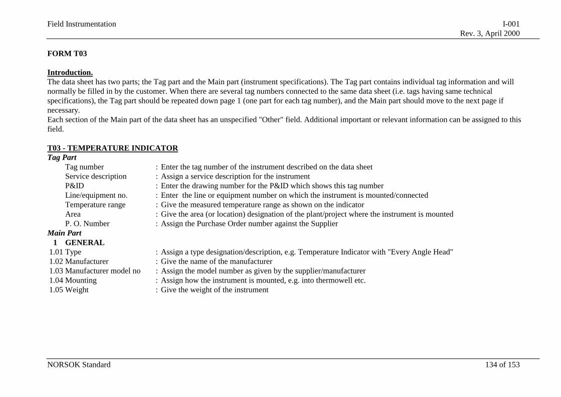
Field Instrumentation I-001Rev. 3, April 2000
NORSOK Standard 134 of 153
FORM T03
Introduction.The data sheet has two parts; the Tag part and the Main part (instrument specifications). The Tag part contains individual tag information and willnormally be filled in by the customer. When there are several tag numbers connected to the same data sheet (i.e. tags having same technicalspecifications), the Tag part should be repeated down page 1 (one part for each tag number), and the Main part should move to the next page ifnecessary.Each section of the Main part of the data sheet has an unspecified "Other" field. Additional important or relevant information can be assigned to thisfield.
T03 - TEMPERATURE INDICATORTag Part
Tag number : Enter the tag number of the instrument described on the data sheetService description : Assign a service description for the instrumentP&ID : Enter the drawing number for the P&ID which shows this tag numberLine/equipment no. : Enter the line or equipment number on which the instrument is mounted/connectedTemperature range : Give the measured temperature range as shown on the indicatorArea : Give the area (or location) designation of the plant/project where the instrument is mountedP. O. Number : Assign the Purchase Order number against the Supplier
Main Part1 GENERAL
1.01 Type : Assign a type designation/description, e.g. Temperature Indicator with "Every Angle Head"1.02 Manufacturer : Give the name of the manufacturer1.03 Manufacturer model no : Assign the model number as given by the supplier/manufacturer1.04 Mounting : Assign how the instrument is mounted, e.g. into thermowell etc.1.05 Weight : Give the weight of the instrument
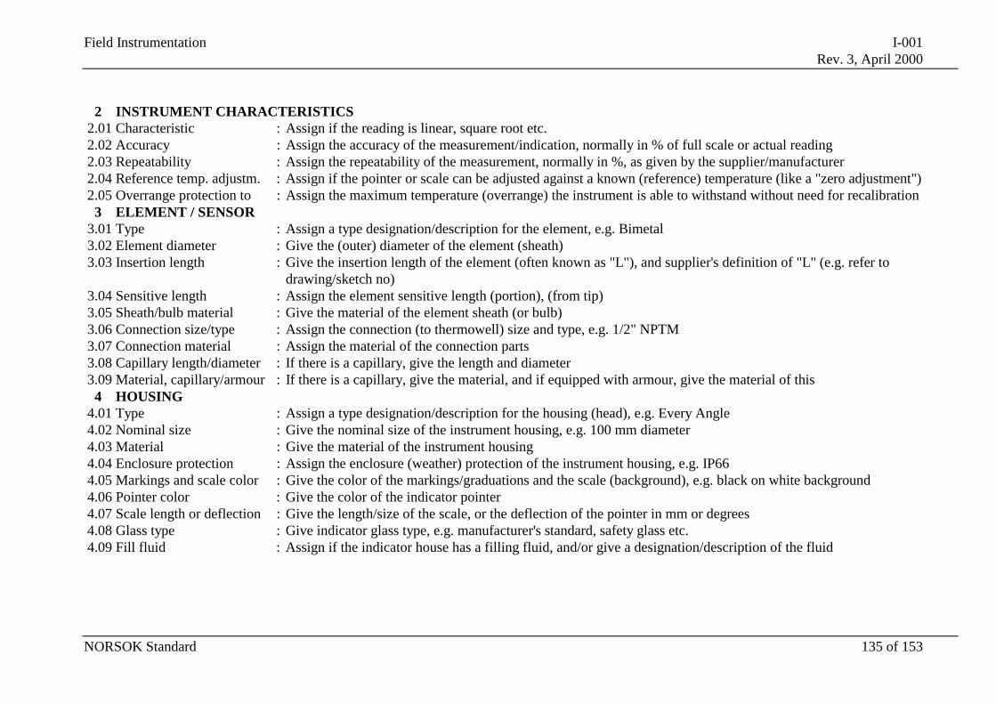
Field Instrumentation I-001Rev. 3, April 2000
NORSOK Standard 135 of 153
2 INSTRUMENT CHARACTERISTICS2.01 Characteristic : Assign if the reading is linear, square root etc.2.02 Accuracy : Assign the accuracy of the measurement/indication, normally in % of full scale or actual reading2.03 Repeatability : Assign the repeatability of the measurement, normally in %, as given by the supplier/manufacturer2.04 Reference temp. adjustm. : Assign if the pointer or scale can be adjusted against a known (reference) temperature (like a "zero adjustment")2.05 Overrange protection to : Assign the maximum temperature (overrange) the instrument is able to withstand without need for recalibration
3 ELEMENT / SENSOR3.01 Type : Assign a type designation/description for the element, e.g. Bimetal3.02 Element diameter : Give the (outer) diameter of the element (sheath)3.03 Insertion length : Give the insertion length of the element (often known as "L"), and supplier's definition of "L" (e.g. refer to
drawing/sketch no)3.04 Sensitive length : Assign the element sensitive length (portion), (from tip)3.05 Sheath/bulb material : Give the material of the element sheath (or bulb)3.06 Connection size/type : Assign the connection (to thermowell) size and type, e.g. 1/2" NPTM3.07 Connection material : Assign the material of the connection parts3.08 Capillary length/diameter : If there is a capillary, give the length and diameter3.09 Material, capillary/armour : If there is a capillary, give the material, and if equipped with armour, give the material of this
4 HOUSING4.01 Type : Assign a type designation/description for the housing (head), e.g. Every Angle4.02 Nominal size : Give the nominal size of the instrument housing, e.g. 100 mm diameter4.03 Material : Give the material of the instrument housing4.04 Enclosure protection : Assign the enclosure (weather) protection of the instrument housing, e.g. IP664.05 Markings and scale color : Give the color of the markings/graduations and the scale (background), e.g. black on white background4.06 Pointer color : Give the color of the indicator pointer4.07 Scale length or deflection : Give the length/size of the scale, or the deflection of the pointer in mm or degrees4.08 Glass type : Give indicator glass type, e.g. manufacturer's standard, safety glass etc.4.09 Fill fluid : Assign if the indicator house has a filling fluid, and/or give a designation/description of the fluid
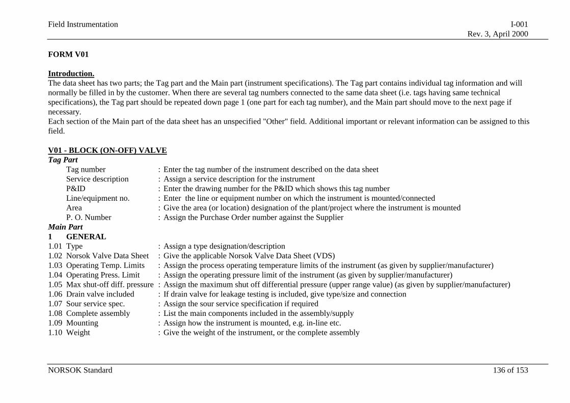
Field Instrumentation I-001Rev. 3, April 2000
NORSOK Standard 136 of 153
FORM V01
Introduction.The data sheet has two parts; the Tag part and the Main part (instrument specifications). The Tag part contains individual tag information and willnormally be filled in by the customer. When there are several tag numbers connected to the same data sheet (i.e. tags having same technicalspecifications), the Tag part should be repeated down page 1 (one part for each tag number), and the Main part should move to the next page ifnecessary.Each section of the Main part of the data sheet has an unspecified "Other" field. Additional important or relevant information can be assigned to thisfield.
V01 - BLOCK (ON-OFF) VALVETag Part
Tag number : Enter the tag number of the instrument described on the data sheetService description : Assign a service description for the instrumentP&ID : Enter the drawing number for the P&ID which shows this tag numberLine/equipment no. : Enter the line or equipment number on which the instrument is mounted/connectedArea : Give the area (or location) designation of the plant/project where the instrument is mountedP. O. Number : Assign the Purchase Order number against the Supplier
Main Part1 GENERAL1.01 Type : Assign a type designation/description1.02 Norsok Valve Data Sheet : Give the applicable Norsok Valve Data Sheet (VDS)1.03 Operating Temp. Limits : Assign the process operating temperature limits of the instrument (as given by supplier/manufacturer)1.04 Operating Press. Limit : Assign the operating pressure limit of the instrument (as given by supplier/manufacturer)1.05 Max shut-off diff. pressure : Assign the maximum shut off differential pressure (upper range value) (as given by supplier/manufacturer)1.06 Drain valve included : If drain valve for leakage testing is included, give type/size and connection1.07 Sour service spec. : Assign the sour service specification if required1.08 Complete assembly : List the main components included in the assembly/supply1.09 Mounting : Assign how the instrument is mounted, e.g. in-line etc.1.10 Weight : Give the weight of the instrument, or the complete assembly
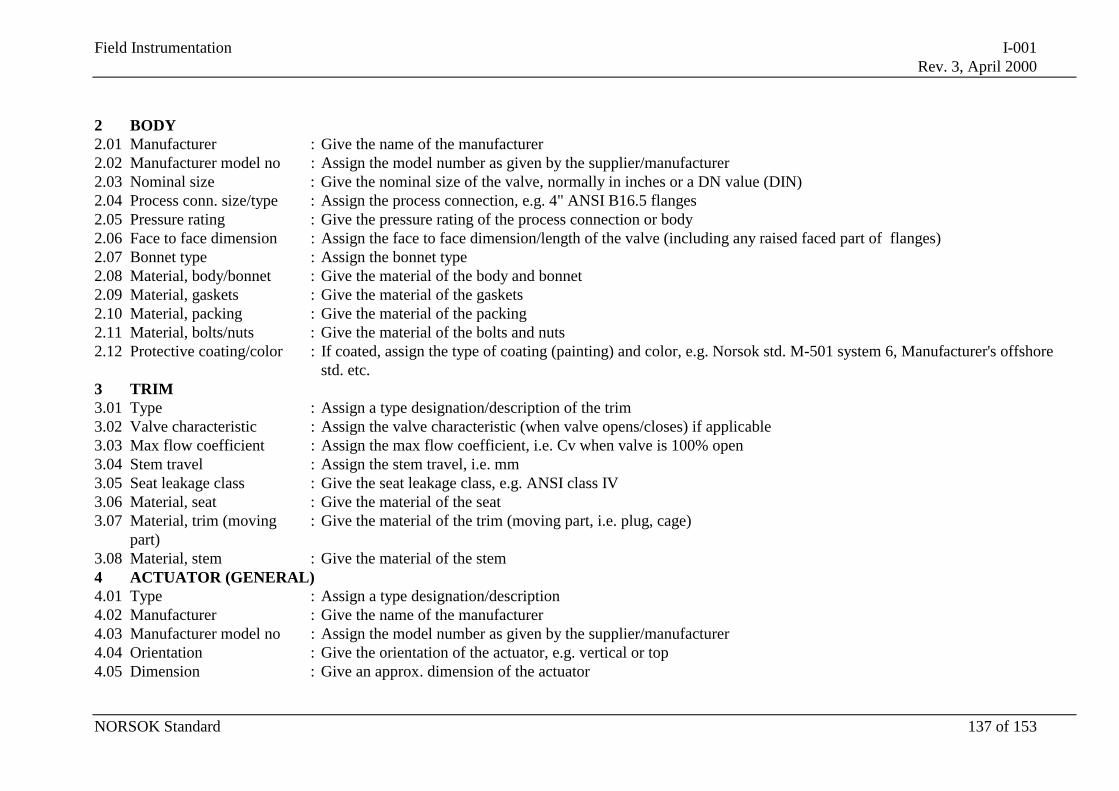
Field Instrumentation I-001Rev. 3, April 2000
NORSOK Standard 137 of 153
2 BODY2.01 Manufacturer : Give the name of the manufacturer2.02 Manufacturer model no : Assign the model number as given by the supplier/manufacturer2.03 Nominal size : Give the nominal size of the valve, normally in inches or a DN value (DIN)2.04 Process conn. size/type : Assign the process connection, e.g. 4" ANSI B16.5 flanges2.05 Pressure rating : Give the pressure rating of the process connection or body2.06 Face to face dimension : Assign the face to face dimension/length of the valve (including any raised faced part of flanges)2.07 Bonnet type : Assign the bonnet type2.08 Material, body/bonnet : Give the material of the body and bonnet2.09 Material, gaskets : Give the material of the gaskets2.10 Material, packing : Give the material of the packing2.11 Material, bolts/nuts : Give the material of the bolts and nuts2.12 Protective coating/color : If coated, assign the type of coating (painting) and color, e.g. Norsok std. M-501 system 6, Manufacturer's offshore
std. etc.3 TRIM3.01 Type : Assign a type designation/description of the trim3.02 Valve characteristic : Assign the valve characteristic (when valve opens/closes) if applicable3.03 Max flow coefficient : Assign the max flow coefficient, i.e. Cv when valve is 100% open3.04 Stem travel : Assign the stem travel, i.e. mm3.05 Seat leakage class : Give the seat leakage class, e.g. ANSI class IV3.06 Material, seat : Give the material of the seat3.07 Material, trim (moving
part): Give the material of the trim (moving part, i.e. plug, cage)
3.08 Material, stem : Give the material of the stem4 ACTUATOR (GENERAL)4.01 Type : Assign a type designation/description4.02 Manufacturer : Give the name of the manufacturer4.03 Manufacturer model no : Assign the model number as given by the supplier/manufacturer4.04 Orientation : Give the orientation of the actuator, e.g. vertical or top4.05 Dimension : Give an approx. dimension of the actuator
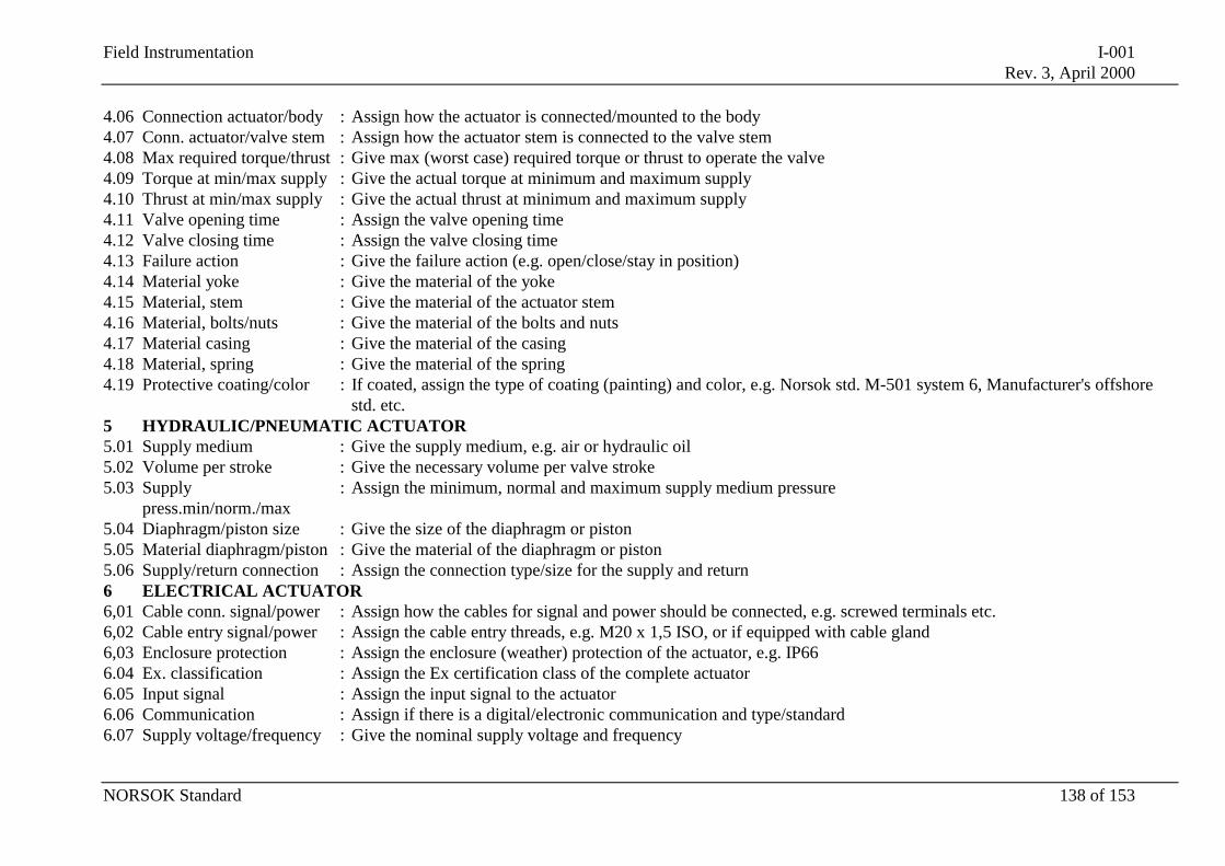
Field Instrumentation I-001Rev. 3, April 2000
NORSOK Standard 138 of 153
4.06 Connection actuator/body : Assign how the actuator is connected/mounted to the body4.07 Conn. actuator/valve stem : Assign how the actuator stem is connected to the valve stem4.08 Max required torque/thrust : Give max (worst case) required torque or thrust to operate the valve4.09 Torque at min/max supply : Give the actual torque at minimum and maximum supply4.10 Thrust at min/max supply : Give the actual thrust at minimum and maximum supply4.11 Valve opening time : Assign the valve opening time4.12 Valve closing time : Assign the valve closing time4.13 Failure action : Give the failure action (e.g. open/close/stay in position)4.14 Material yoke : Give the material of the yoke4.15 Material, stem : Give the material of the actuator stem4.16 Material, bolts/nuts : Give the material of the bolts and nuts4.17 Material casing : Give the material of the casing4.18 Material, spring : Give the material of the spring4.19 Protective coating/color : If coated, assign the type of coating (painting) and color, e.g. Norsok std. M-501 system 6, Manufacturer's offshore
std. etc.5 HYDRAULIC/PNEUMATIC ACTUATOR5.01 Supply medium : Give the supply medium, e.g. air or hydraulic oil5.02 Volume per stroke : Give the necessary volume per valve stroke5.03 Supply
press.min/norm./max: Assign the minimum, normal and maximum supply medium pressure
5.04 Diaphragm/piston size : Give the size of the diaphragm or piston5.05 Material diaphragm/piston : Give the material of the diaphragm or piston5.06 Supply/return connection : Assign the connection type/size for the supply and return6 ELECTRICAL ACTUATOR6,01 Cable conn. signal/power : Assign how the cables for signal and power should be connected, e.g. screwed terminals etc.6,02 Cable entry signal/power : Assign the cable entry threads, e.g. M20 x 1,5 ISO, or if equipped with cable gland6,03 Enclosure protection : Assign the enclosure (weather) protection of the actuator, e.g. IP666.04 Ex. classification : Assign the Ex certification class of the complete actuator6.05 Input signal : Assign the input signal to the actuator6.06 Communication : Assign if there is a digital/electronic communication and type/standard6.07 Supply voltage/frequency : Give the nominal supply voltage and frequency
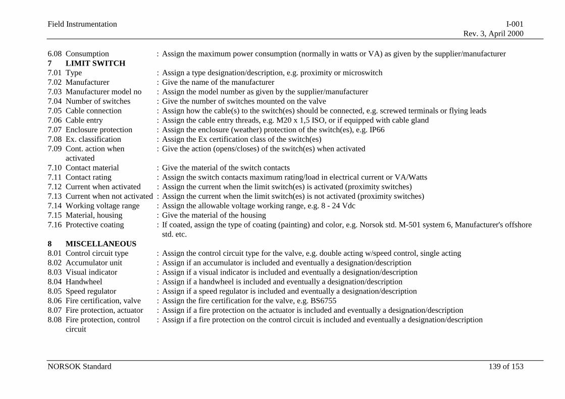
Field Instrumentation I-001Rev. 3, April 2000
NORSOK Standard 139 of 153
6.08 Consumption : Assign the maximum power consumption (normally in watts or VA) as given by the supplier/manufacturer7 LIMIT SWITCH7.01 Type : Assign a type designation/description, e.g. proximity or microswitch7.02 Manufacturer : Give the name of the manufacturer7.03 Manufacturer model no : Assign the model number as given by the supplier/manufacturer7.04 Number of switches : Give the number of switches mounted on the valve7.05 Cable connection : Assign how the cable(s) to the switch(es) should be connected, e.g. screwed terminals or flying leads7.06 Cable entry : Assign the cable entry threads, e.g. M20 x 1,5 ISO, or if equipped with cable gland7.07 Enclosure protection : Assign the enclosure (weather) protection of the switch(es), e.g. IP667.08 Ex. classification : Assign the Ex certification class of the switch(es)7.09 Cont. action when
activated: Give the action (opens/closes) of the switch(es) when activated
7.10 Contact material : Give the material of the switch contacts7.11 Contact rating : Assign the switch contacts maximum rating/load in electrical current or VA/Watts7.12 Current when activated : Assign the current when the limit switch(es) is activated (proximity switches)7.13 Current when not activated : Assign the current when the limit switch(es) is not activated (proximity switches)7.14 Working voltage range : Assign the allowable voltage working range, e.g. 8 - 24 Vdc7.15 Material, housing : Give the material of the housing7.16 Protective coating : If coated, assign the type of coating (painting) and color, e.g. Norsok std. M-501 system 6, Manufacturer's offshore
std. etc.8 MISCELLANEOUS8.01 Control circuit type : Assign the control circuit type for the valve, e.g. double acting w/speed control, single acting8.02 Accumulator unit : Assign if an accumulator is included and eventually a designation/description8.03 Visual indicator : Assign if a visual indicator is included and eventually a designation/description8.04 Handwheel : Assign if a handwheel is included and eventually a designation/description8.05 Speed regulator : Assign if a speed regulator is included and eventually a designation/description8.06 Fire certification, valve : Assign the fire certification for the valve, e.g. BS67558.07 Fire protection, actuator : Assign if a fire protection on the actuator is included and eventually a designation/description8.08 Fire protection, control
circuit: Assign if a fire protection on the control circuit is included and eventually a designation/description
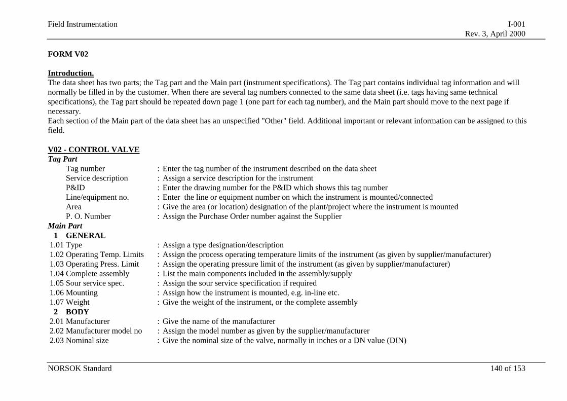
Field Instrumentation I-001Rev. 3, April 2000
NORSOK Standard 140 of 153
FORM V02
Introduction.The data sheet has two parts; the Tag part and the Main part (instrument specifications). The Tag part contains individual tag information and willnormally be filled in by the customer. When there are several tag numbers connected to the same data sheet (i.e. tags having same technicalspecifications), the Tag part should be repeated down page 1 (one part for each tag number), and the Main part should move to the next page ifnecessary.Each section of the Main part of the data sheet has an unspecified "Other" field. Additional important or relevant information can be assigned to thisfield.
V02 - CONTROL VALVETag Part
Tag number : Enter the tag number of the instrument described on the data sheetService description : Assign a service description for the instrumentP&ID : Enter the drawing number for the P&ID which shows this tag numberLine/equipment no. : Enter the line or equipment number on which the instrument is mounted/connectedArea : Give the area (or location) designation of the plant/project where the instrument is mountedP. O. Number : Assign the Purchase Order number against the Supplier
Main Part1 GENERAL
1.01 Type : Assign a type designation/description1.02 Operating Temp. Limits : Assign the process operating temperature limits of the instrument (as given by supplier/manufacturer)1.03 Operating Press. Limit : Assign the operating pressure limit of the instrument (as given by supplier/manufacturer)1.04 Complete assembly : List the main components included in the assembly/supply1.05 Sour service spec. : Assign the sour service specification if required1.06 Mounting : Assign how the instrument is mounted, e.g. in-line etc.1.07 Weight : Give the weight of the instrument, or the complete assembly
2 BODY2.01 Manufacturer : Give the name of the manufacturer2.02 Manufacturer model no : Assign the model number as given by the supplier/manufacturer2.03 Nominal size : Give the nominal size of the valve, normally in inches or a DN value (DIN)
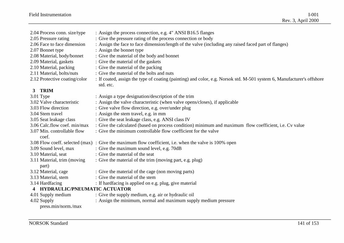
Field Instrumentation I-001Rev. 3, April 2000
NORSOK Standard 141 of 153
2.04 Process conn. size/type : Assign the process connection, e.g. 4" ANSI B16.5 flanges2.05 Pressure rating : Give the pressure rating of the process connection or body2.06 Face to face dimension : Assign the face to face dimension/length of the valve (including any raised faced part of flanges)2.07 Bonnet type : Assign the bonnet type2.08 Material, body/bonnet : Give the material of the body and bonnet2.09 Material, gaskets : Give the material of the gaskets2.10 Material, packing : Give the material of the packing2.11 Material, bolts/nuts : Give the material of the bolts and nuts2.12 Protective coating/color : If coated, assign the type of coating (painting) and color, e.g. Norsok std. M-501 system 6, Manufacturer's offshore
std. etc.3 TRIM
3.01 Type : Assign a type designation/description of the trim3.02 Valve characteristic : Assign the valve characteristic (when valve opens/closes), if applicable3.03 Flow direction : Give valve flow direction, e.g. over/under plug3.04 Stem travel : Assign the stem travel, e.g. in mm3.05 Seat leakage class : Give the seat leakage class, e.g. ANSI class IV3.06 Calc.flow coef. min/max : Give the calculated (based on process condition) minimum and maximum flow coefficient, i.e. Cv value3.07 Min. controllable flow
coef.: Give the minimum controllable flow coefficient for the valve
3.08 Flow coeff. selected (max) : Give the maximum flow coefficient, i.e. when the valve is 100% open3.09 Sound level, max : Give the maximum sound level, e.g. 70dB3.10 Material, seat : Give the material of the seat3.11 Material, trim (moving
part): Give the material of the trim (moving part, e.g. plug)
3.12 Material, cage : Give the material of the cage (non moving parts)3.13 Material, stem : Give the material of the stem3.14 Hardfacing : If hardfacing is applied on e.g. plug, give material
4 HYDRAULIC/PNEUMATIC ACTUATOR4.01 Supply medium : Give the supply medium, e.g. air or hydraulic oil4.02 Supply
press.min/norm./max: Assign the minimum, normal and maximum supply medium pressure
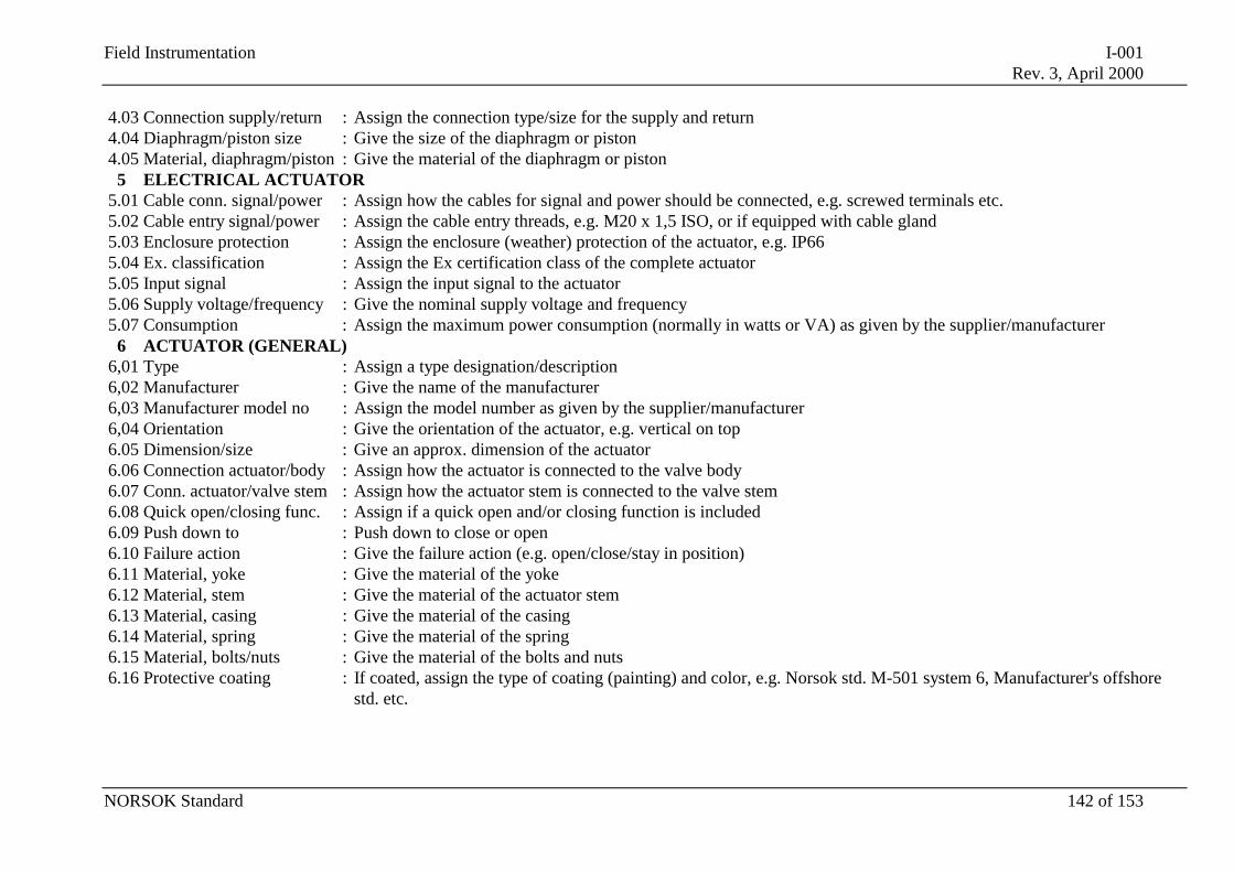
Field Instrumentation I-001Rev. 3, April 2000
NORSOK Standard 142 of 153
4.03 Connection supply/return : Assign the connection type/size for the supply and return4.04 Diaphragm/piston size : Give the size of the diaphragm or piston4.05 Material, diaphragm/piston : Give the material of the diaphragm or piston
5 ELECTRICAL ACTUATOR5.01 Cable conn. signal/power : Assign how the cables for signal and power should be connected, e.g. screwed terminals etc.5.02 Cable entry signal/power : Assign the cable entry threads, e.g. M20 x 1,5 ISO, or if equipped with cable gland5.03 Enclosure protection : Assign the enclosure (weather) protection of the actuator, e.g. IP665.04 Ex. classification : Assign the Ex certification class of the complete actuator5.05 Input signal : Assign the input signal to the actuator5.06 Supply voltage/frequency : Give the nominal supply voltage and frequency5.07 Consumption : Assign the maximum power consumption (normally in watts or VA) as given by the supplier/manufacturer
6 ACTUATOR (GENERAL)6,01 Type : Assign a type designation/description6,02 Manufacturer : Give the name of the manufacturer6,03 Manufacturer model no : Assign the model number as given by the supplier/manufacturer6,04 Orientation : Give the orientation of the actuator, e.g. vertical on top6.05 Dimension/size : Give an approx. dimension of the actuator6.06 Connection actuator/body : Assign how the actuator is connected to the valve body6.07 Conn. actuator/valve stem : Assign how the actuator stem is connected to the valve stem6.08 Quick open/closing func. : Assign if a quick open and/or closing function is included6.09 Push down to : Push down to close or open6.10 Failure action : Give the failure action (e.g. open/close/stay in position)6.11 Material, yoke : Give the material of the yoke6.12 Material, stem : Give the material of the actuator stem6.13 Material, casing : Give the material of the casing6.14 Material, spring : Give the material of the spring6.15 Material, bolts/nuts : Give the material of the bolts and nuts6.16 Protective coating : If coated, assign the type of coating (painting) and color, e.g. Norsok std. M-501 system 6, Manufacturer's offshore
std. etc.
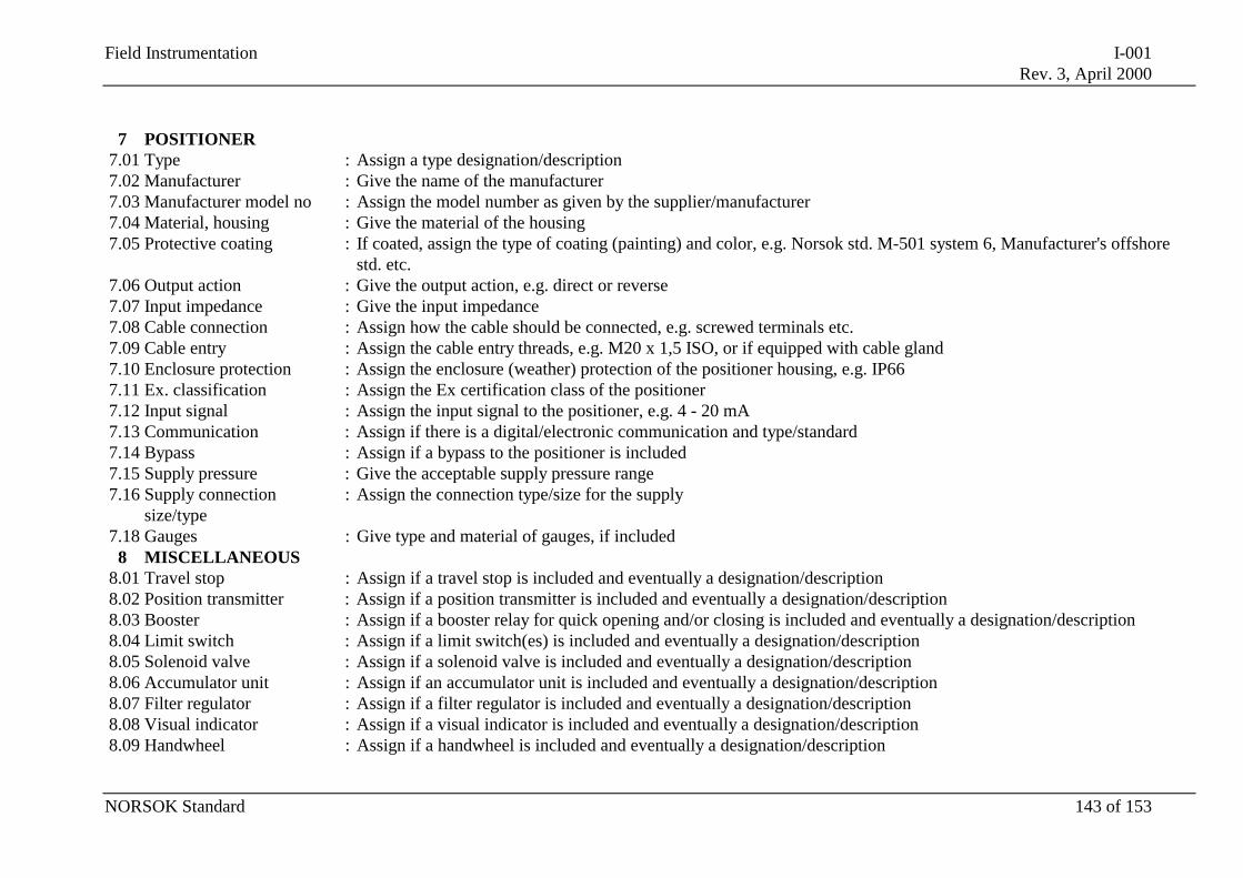
Field Instrumentation I-001Rev. 3, April 2000
NORSOK Standard 143 of 153
7 POSITIONER7.01 Type : Assign a type designation/description7.02 Manufacturer : Give the name of the manufacturer7.03 Manufacturer model no : Assign the model number as given by the supplier/manufacturer7.04 Material, housing : Give the material of the housing7.05 Protective coating : If coated, assign the type of coating (painting) and color, e.g. Norsok std. M-501 system 6, Manufacturer's offshore
std. etc.7.06 Output action : Give the output action, e.g. direct or reverse7.07 Input impedance : Give the input impedance7.08 Cable connection : Assign how the cable should be connected, e.g. screwed terminals etc.7.09 Cable entry : Assign the cable entry threads, e.g. M20 x 1,5 ISO, or if equipped with cable gland7.10 Enclosure protection : Assign the enclosure (weather) protection of the positioner housing, e.g. IP667.11 Ex. classification : Assign the Ex certification class of the positioner7.12 Input signal : Assign the input signal to the positioner, e.g. 4 - 20 mA7.13 Communication : Assign if there is a digital/electronic communication and type/standard7.14 Bypass : Assign if a bypass to the positioner is included7.15 Supply pressure : Give the acceptable supply pressure range7.16 Supply connection
size/type: Assign the connection type/size for the supply
7.18 Gauges : Give type and material of gauges, if included8 MISCELLANEOUS
8.01 Travel stop : Assign if a travel stop is included and eventually a designation/description8.02 Position transmitter : Assign if a position transmitter is included and eventually a designation/description8.03 Booster : Assign if a booster relay for quick opening and/or closing is included and eventually a designation/description8.04 Limit switch : Assign if a limit switch(es) is included and eventually a designation/description8.05 Solenoid valve : Assign if a solenoid valve is included and eventually a designation/description8.06 Accumulator unit : Assign if an accumulator unit is included and eventually a designation/description8.07 Filter regulator : Assign if a filter regulator is included and eventually a designation/description8.08 Visual indicator : Assign if a visual indicator is included and eventually a designation/description8.09 Handwheel : Assign if a handwheel is included and eventually a designation/description
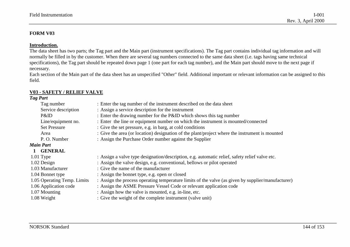
Field Instrumentation I-001Rev. 3, April 2000
NORSOK Standard 144 of 153
FORM V03
Introduction.The data sheet has two parts; the Tag part and the Main part (instrument specifications). The Tag part contains individual tag information and willnormally be filled in by the customer. When there are several tag numbers connected to the same data sheet (i.e. tags having same technicalspecifications), the Tag part should be repeated down page 1 (one part for each tag number), and the Main part should move to the next page ifnecessary.Each section of the Main part of the data sheet has an unspecified "Other" field. Additional important or relevant information can be assigned to thisfield.
V03 - SAFETY / RELIEF VALVETag Part
Tag number : Enter the tag number of the instrument described on the data sheetService description : Assign a service description for the instrumentP&ID : Enter the drawing number for the P&ID which shows this tag numberLine/equipment no. : Enter the line or equipment number on which the instrument is mounted/connectedSet Pressure : Give the set pressure, e.g. in barg, at cold conditionsArea : Give the area (or location) designation of the plant/project where the instrument is mountedP. O. Number : Assign the Purchase Order number against the Supplier
Main Part1 GENERAL
1.01 Type : Assign a valve type designation/description, e.g. automatic relief, safety relief valve etc.1.02 Design : Assign the valve design, e.g. conventional, bellows or pilot operated1.03 Manufacturer : Give the name of the manufacturer1.04 Bonnet type : Assign the bonnet type, e.g. open or closed1.05 Operating Temp. Limits : Assign the process operating temperature limits of the valve (as given by supplier/manufacturer)1.06 Application code : Assign the ASME Pressure Vessel Code or relevant application code1.07 Mounting : Assign how the valve is mounted, e.g. in-line, etc.1.08 Weight : Give the weight of the complete instrument (valve unit)
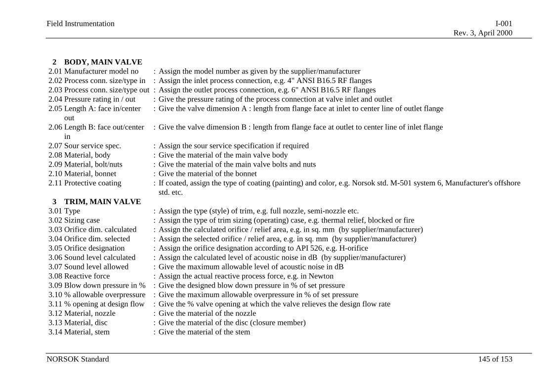
Field Instrumentation I-001Rev. 3, April 2000
NORSOK Standard 145 of 153
2 BODY, MAIN VALVE2.01 Manufacturer model no : Assign the model number as given by the supplier/manufacturer2.02 Process conn. size/type in : Assign the inlet process connection, e.g. 4" ANSI B16.5 RF flanges2.03 Process conn. size/type out : Assign the outlet process connection, e.g. 6" ANSI B16.5 RF flanges2.04 Pressure rating in / out : Give the pressure rating of the process connection at valve inlet and outlet2.05 Length A: face in/center
out: Give the valve dimension A : length from flange face at inlet to center line of outlet flange
2.06 Length B: face out/centerin
: Give the valve dimension B : length from flange face at outlet to center line of inlet flange
2.07 Sour service spec. : Assign the sour service specification if required2.08 Material, body : Give the material of the main valve body2.09 Material, bolt/nuts : Give the material of the main valve bolts and nuts2.10 Material, bonnet : Give the material of the bonnet2.11 Protective coating : If coated, assign the type of coating (painting) and color, e.g. Norsok std. M-501 system 6, Manufacturer's offshore
std. etc.3 TRIM, MAIN VALVE
3.01 Type : Assign the type (style) of trim, e.g. full nozzle, semi-nozzle etc.3.02 Sizing case : Assign the type of trim sizing (operating) case, e.g. thermal relief, blocked or fire3.03 Orifice dim. calculated : Assign the calculated orifice / relief area, e.g. in sq. mm (by supplier/manufacturer)3.04 Orifice dim. selected : Assign the selected orifice / relief area, e.g. in sq. mm (by supplier/manufacturer)3.05 Orifice designation : Assign the orifice designation according to API 526, e.g. H-orifice3.06 Sound level calculated : Assign the calculated level of acoustic noise in dB (by supplier/manufacturer)3.07 Sound level allowed : Give the maximum allowable level of acoustic noise in dB3.08 Reactive force : Assign the actual reactive process force, e.g. in Newton3.09 Blow down pressure in % : Give the designed blow down pressure in % of set pressure3.10 % allowable overpressure : Give the maximum allowable overpressure in % of set pressure3.11 % opening at design flow : Give the % valve opening at which the valve relieves the design flow rate3.12 Material, nozzle : Give the material of the nozzle3.13 Material, disc : Give the material of the disc (closure member)3.14 Material, stem : Give the material of the stem
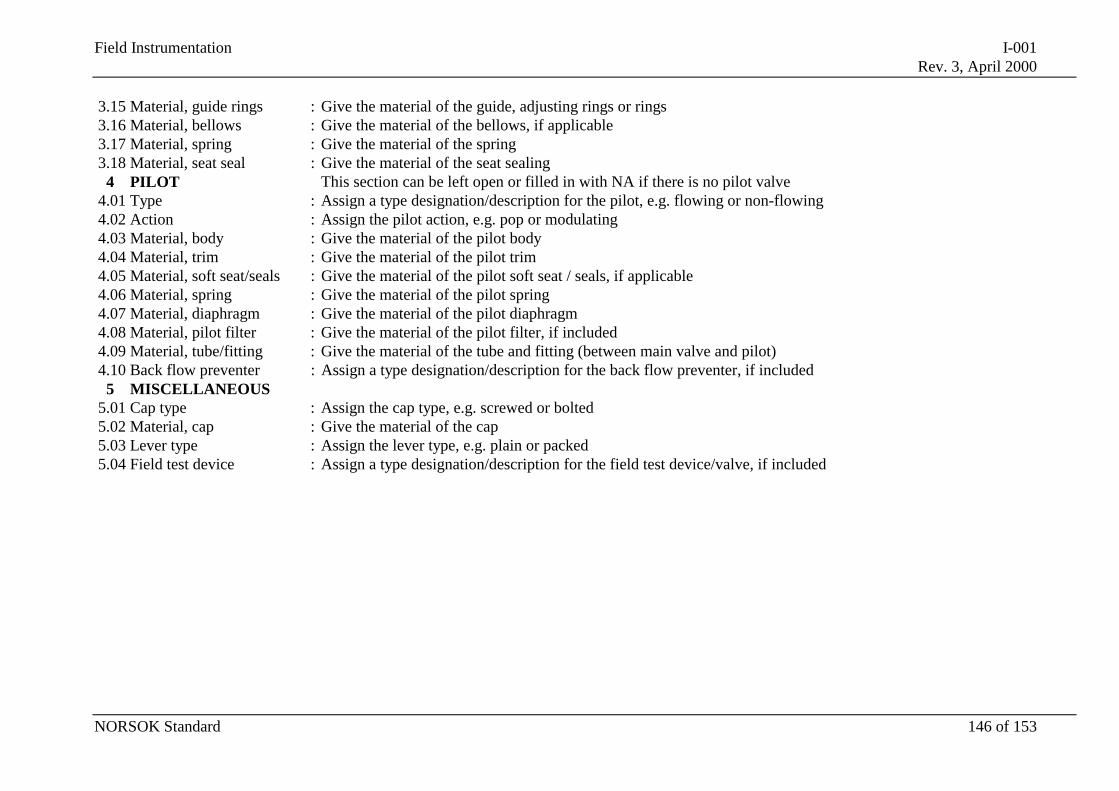
Field Instrumentation I-001Rev. 3, April 2000
NORSOK Standard 146 of 153
3.15 Material, guide rings : Give the material of the guide, adjusting rings or rings3.16 Material, bellows : Give the material of the bellows, if applicable3.17 Material, spring : Give the material of the spring3.18 Material, seat seal : Give the material of the seat sealing
4 PILOT This section can be left open or filled in with NA if there is no pilot valve4.01 Type : Assign a type designation/description for the pilot, e.g. flowing or non-flowing4.02 Action : Assign the pilot action, e.g. pop or modulating4.03 Material, body : Give the material of the pilot body4.04 Material, trim : Give the material of the pilot trim4.05 Material, soft seat/seals : Give the material of the pilot soft seat / seals, if applicable4.06 Material, spring : Give the material of the pilot spring4.07 Material, diaphragm : Give the material of the pilot diaphragm4.08 Material, pilot filter : Give the material of the pilot filter, if included4.09 Material, tube/fitting : Give the material of the tube and fitting (between main valve and pilot)4.10 Back flow preventer : Assign a type designation/description for the back flow preventer, if included
5 MISCELLANEOUS5.01 Cap type : Assign the cap type, e.g. screwed or bolted5.02 Material, cap : Give the material of the cap5.03 Lever type : Assign the lever type, e.g. plain or packed5.04 Field test device : Assign a type designation/description for the field test device/valve, if included
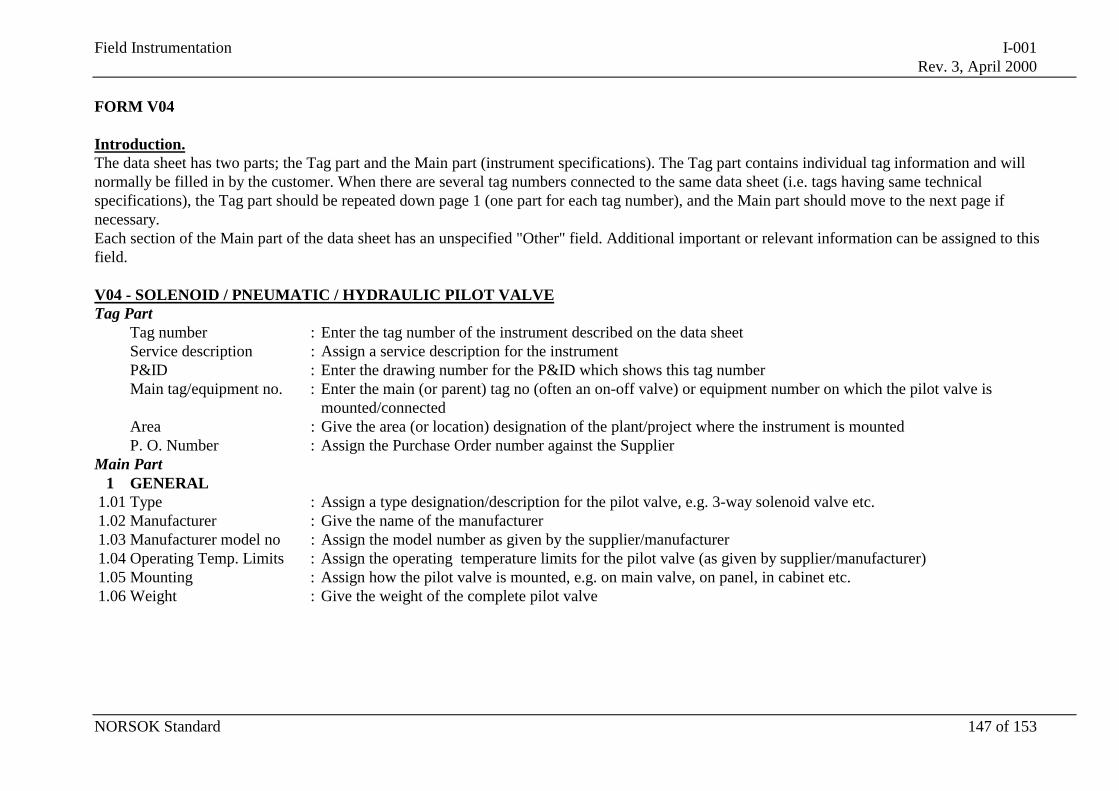
Field Instrumentation I-001Rev. 3, April 2000
NORSOK Standard 147 of 153
FORM V04
Introduction.The data sheet has two parts; the Tag part and the Main part (instrument specifications). The Tag part contains individual tag information and willnormally be filled in by the customer. When there are several tag numbers connected to the same data sheet (i.e. tags having same technicalspecifications), the Tag part should be repeated down page 1 (one part for each tag number), and the Main part should move to the next page ifnecessary.Each section of the Main part of the data sheet has an unspecified "Other" field. Additional important or relevant information can be assigned to thisfield.
V04 - SOLENOID / PNEUMATIC / HYDRAULIC PILOT VALVETag Part
Tag number : Enter the tag number of the instrument described on the data sheetService description : Assign a service description for the instrumentP&ID : Enter the drawing number for the P&ID which shows this tag numberMain tag/equipment no. : Enter the main (or parent) tag no (often an on-off valve) or equipment number on which the pilot valve is
mounted/connectedArea : Give the area (or location) designation of the plant/project where the instrument is mountedP. O. Number : Assign the Purchase Order number against the Supplier
Main Part1 GENERAL
1.01 Type : Assign a type designation/description for the pilot valve, e.g. 3-way solenoid valve etc.1.02 Manufacturer : Give the name of the manufacturer1.03 Manufacturer model no : Assign the model number as given by the supplier/manufacturer1.04 Operating Temp. Limits : Assign the operating temperature limits for the pilot valve (as given by supplier/manufacturer)1.05 Mounting : Assign how the pilot valve is mounted, e.g. on main valve, on panel, in cabinet etc.1.06 Weight : Give the weight of the complete pilot valve
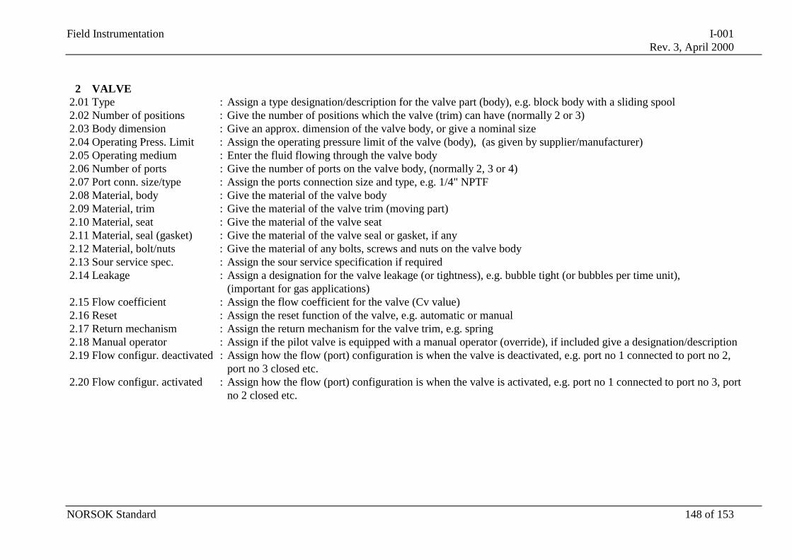
Field Instrumentation I-001Rev. 3, April 2000
NORSOK Standard 148 of 153
2 VALVE2.01 Type : Assign a type designation/description for the valve part (body), e.g. block body with a sliding spool2.02 Number of positions : Give the number of positions which the valve (trim) can have (normally 2 or 3)2.03 Body dimension : Give an approx. dimension of the valve body, or give a nominal size2.04 Operating Press. Limit : Assign the operating pressure limit of the valve (body), (as given by supplier/manufacturer)2.05 Operating medium : Enter the fluid flowing through the valve body2.06 Number of ports : Give the number of ports on the valve body, (normally 2, 3 or 4)2.07 Port conn. size/type : Assign the ports connection size and type, e.g. 1/4" NPTF2.08 Material, body : Give the material of the valve body2.09 Material, trim : Give the material of the valve trim (moving part)2.10 Material, seat : Give the material of the valve seat2.11 Material, seal (gasket) : Give the material of the valve seal or gasket, if any2.12 Material, bolt/nuts : Give the material of any bolts, screws and nuts on the valve body2.13 Sour service spec. : Assign the sour service specification if required2.14 Leakage : Assign a designation for the valve leakage (or tightness), e.g. bubble tight (or bubbles per time unit),
(important for gas applications)2.15 Flow coefficient : Assign the flow coefficient for the valve (Cv value)2.16 Reset : Assign the reset function of the valve, e.g. automatic or manual2.17 Return mechanism : Assign the return mechanism for the valve trim, e.g. spring2.18 Manual operator : Assign if the pilot valve is equipped with a manual operator (override), if included give a designation/description2.19 Flow configur. deactivated : Assign how the flow (port) configuration is when the valve is deactivated, e.g. port no 1 connected to port no 2,
port no 3 closed etc.2.20 Flow configur. activated : Assign how the flow (port) configuration is when the valve is activated, e.g. port no 1 connected to port no 3, port
no 2 closed etc.
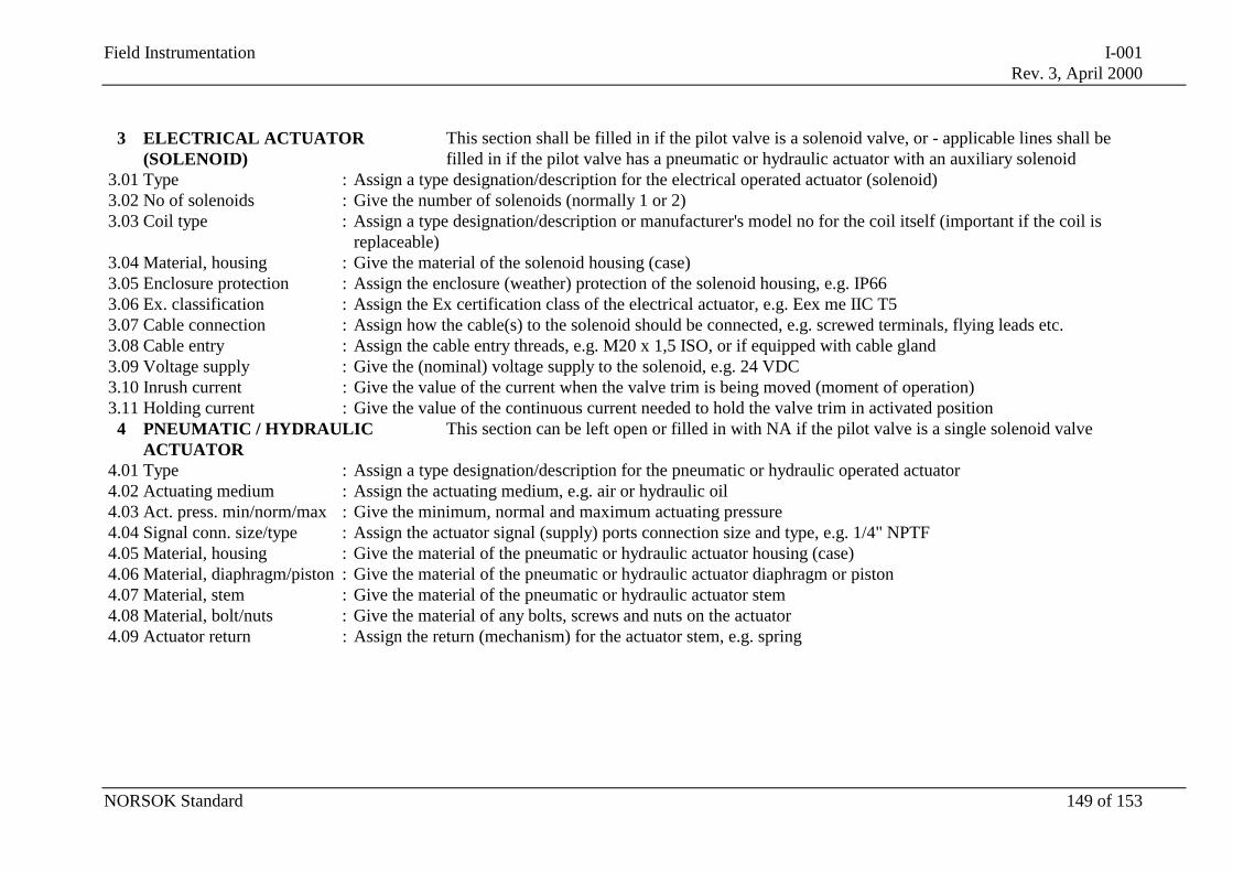
Field Instrumentation I-001Rev. 3, April 2000
NORSOK Standard 149 of 153
3 ELECTRICAL ACTUATOR(SOLENOID)
This section shall be filled in if the pilot valve is a solenoid valve, or - applicable lines shall befilled in if the pilot valve has a pneumatic or hydraulic actuator with an auxiliary solenoid
3.01 Type : Assign a type designation/description for the electrical operated actuator (solenoid)3.02 No of solenoids : Give the number of solenoids (normally 1 or 2)3.03 Coil type : Assign a type designation/description or manufacturer's model no for the coil itself (important if the coil is
replaceable)3.04 Material, housing : Give the material of the solenoid housing (case)3.05 Enclosure protection : Assign the enclosure (weather) protection of the solenoid housing, e.g. IP663.06 Ex. classification : Assign the Ex certification class of the electrical actuator, e.g. Eex me IIC T53.07 Cable connection : Assign how the cable(s) to the solenoid should be connected, e.g. screwed terminals, flying leads etc.3.08 Cable entry : Assign the cable entry threads, e.g. M20 x 1,5 ISO, or if equipped with cable gland3.09 Voltage supply : Give the (nominal) voltage supply to the solenoid, e.g. 24 VDC3.10 Inrush current : Give the value of the current when the valve trim is being moved (moment of operation)3.11 Holding current : Give the value of the continuous current needed to hold the valve trim in activated position
4 PNEUMATIC / HYDRAULICACTUATOR
This section can be left open or filled in with NA if the pilot valve is a single solenoid valve
4.01 Type : Assign a type designation/description for the pneumatic or hydraulic operated actuator4.02 Actuating medium : Assign the actuating medium, e.g. air or hydraulic oil4.03 Act. press. min/norm/max : Give the minimum, normal and maximum actuating pressure4.04 Signal conn. size/type : Assign the actuator signal (supply) ports connection size and type, e.g. 1/4" NPTF4.05 Material, housing : Give the material of the pneumatic or hydraulic actuator housing (case)4.06 Material, diaphragm/piston : Give the material of the pneumatic or hydraulic actuator diaphragm or piston4.07 Material, stem : Give the material of the pneumatic or hydraulic actuator stem4.08 Material, bolt/nuts : Give the material of any bolts, screws and nuts on the actuator4.09 Actuator return : Assign the return (mechanism) for the actuator stem, e.g. spring
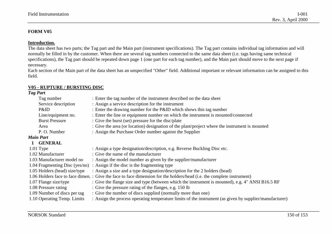
Field Instrumentation I-001Rev. 3, April 2000
NORSOK Standard 150 of 153
FORM V05
Introduction.The data sheet has two parts; the Tag part and the Main part (instrument specifications). The Tag part contains individual tag information and willnormally be filled in by the customer. When there are several tag numbers connected to the same data sheet (i.e. tags having same technicalspecifications), the Tag part should be repeated down page 1 (one part for each tag number), and the Main part should move to the next page ifnecessary.Each section of the Main part of the data sheet has an unspecified "Other" field. Additional important or relevant information can be assigned to thisfield.
V05 - RUPTURE / BURSTING DISCTag Part
Tag number : Enter the tag number of the instrument described on the data sheetService description : Assign a service description for the instrumentP&ID : Enter the drawing number for the P&ID which shows this tag numberLine/equipment no. : Enter the line or equipment number on which the instrument is mounted/connectedBurst Pressure : Give the burst (set) pressure for the disc/plateArea : Give the area (or location) designation of the plant/project where the instrument is mountedP. O. Number : Assign the Purchase Order number against the Supplier
Main Part1 GENERAL
1.01 Type : Assign a type designation/description, e.g. Reverse Buckling Disc etc.1.02 Manufacturer : Give the name of the manufacturer1.03 Manufacturer model no : Assign the model number as given by the supplier/manufacturer1.04 Fragmenting Disc (yes/no) : Assign if the disc is the fragmenting type1.05 Holders (head) size/type : Assign a size and a type designation/description for the 2 holders (head)1.06 Holders face to face dimen. : Give the face to face dimension for the holders/head (i.e. the complete instrument)1.07 Flange size/type : Give the flange size and type (between which the instrument is mounted), e.g. 4" ANSI B16.5 RF1.08 Pressure rating : Give the pressure rating of the flanges, e.g. 150 lb1.09 Number of discs per tag : Give the number of discs supplied (normally more than one)1.10 Operating Temp. Limits : Assign the process operating temperature limits of the instrument (as given by supplier/manufacturer)
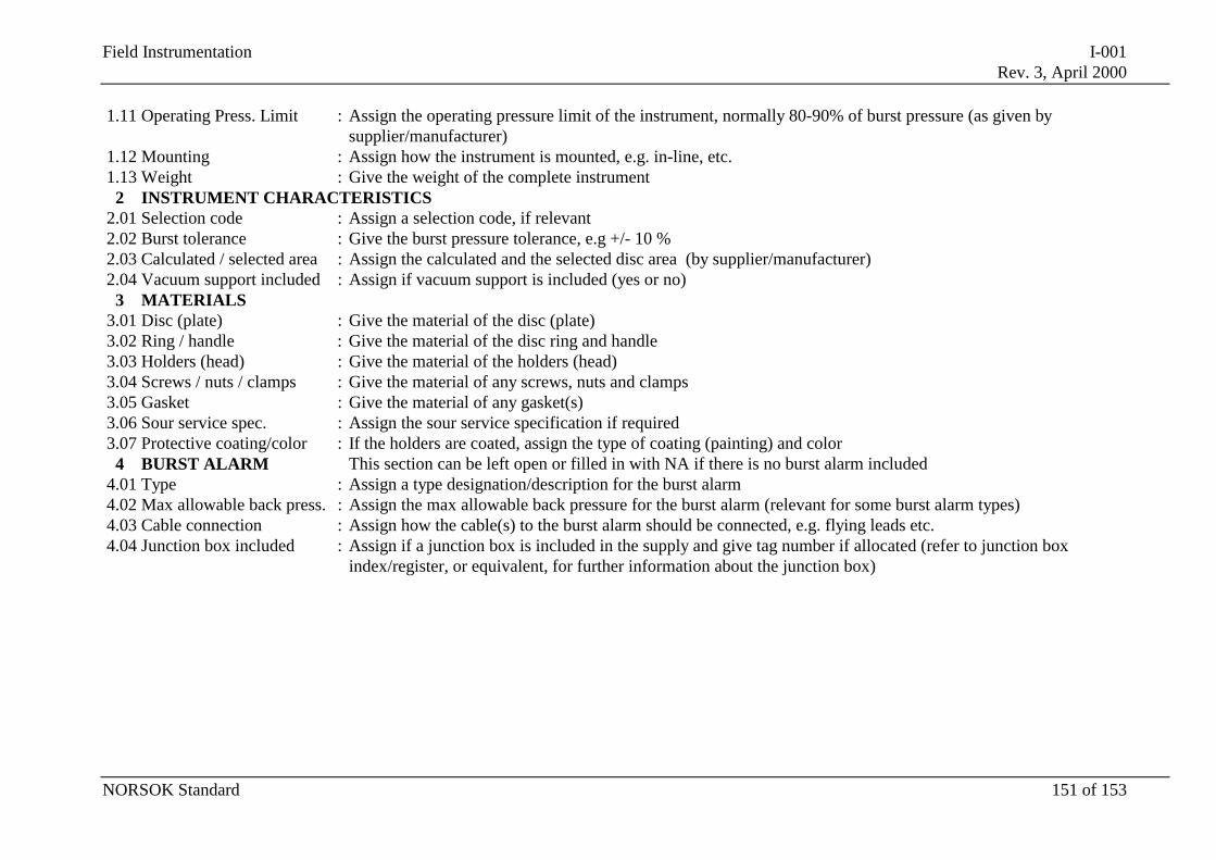
Field Instrumentation I-001Rev. 3, April 2000
NORSOK Standard 151 of 153
1.11 Operating Press. Limit : Assign the operating pressure limit of the instrument, normally 80-90% of burst pressure (as given bysupplier/manufacturer)
1.12 Mounting : Assign how the instrument is mounted, e.g. in-line, etc.1.13 Weight : Give the weight of the complete instrument
2 INSTRUMENT CHARACTERISTICS2.01 Selection code : Assign a selection code, if relevant2.02 Burst tolerance : Give the burst pressure tolerance, e.g +/- 10 %2.03 Calculated / selected area : Assign the calculated and the selected disc area (by supplier/manufacturer)2.04 Vacuum support included : Assign if vacuum support is included (yes or no)
3 MATERIALS3.01 Disc (plate) : Give the material of the disc (plate)3.02 Ring / handle : Give the material of the disc ring and handle3.03 Holders (head) : Give the material of the holders (head)3.04 Screws / nuts / clamps : Give the material of any screws, nuts and clamps3.05 Gasket : Give the material of any gasket(s)3.06 Sour service spec. : Assign the sour service specification if required3.07 Protective coating/color : If the holders are coated, assign the type of coating (painting) and color
4 BURST ALARM This section can be left open or filled in with NA if there is no burst alarm included4.01 Type : Assign a type designation/description for the burst alarm4.02 Max allowable back press. : Assign the max allowable back pressure for the burst alarm (relevant for some burst alarm types)4.03 Cable connection : Assign how the cable(s) to the burst alarm should be connected, e.g. flying leads etc.4.04 Junction box included : Assign if a junction box is included in the supply and give tag number if allocated (refer to junction box
index/register, or equivalent, for further information about the junction box)
Field Instrumentation I-001Rev. 3, April 2000
NORSOK Standard 152 of 153
FORM X01
Introduction.The data sheet has two parts; the Tag part and the Main part (instrument specifications). The Tag part contains individual tag information and willnormally be filled in by the customer. When there are several tag numbers connected to the same data sheet (i.e. tags having same technicalspecifications), the Tag part should be repeated down page 1 (one part for each tag number), and the Main part should move to the next page ifnecessary.This "open" data sheet shall be used for all instruments which are unsuitable for being described/specified on the other data sheet forms.This form shall replace the old IFEA forms A01, K01, K02, K03, K04, I01, I02, Y01, Y02 and Z01.Typical instruments which should be described/specified on this form are:All types of analysers, corrosion instruments, alarm and status lights/indicators, converters (I/P and P/I), dampers, field controllers,all types of hand switches, accumulators, electrical indicators (receiver gauges), vibration instruments, position indicators/transmitters,weightinstruments, flow computers/totalizers, flow glasses, flow switches, recorders, humidity instruments, speed instruments, etc.
X01 - MISCELLANEOUS INSTRUMENTSTag Part
Tag number : Enter the tag number of the instrument described on the data sheetService description : Assign a service description for the instrumentP&ID : Enter the drawing number for the P&ID which shows this tag numberLine/equipment no. : Enter the line or equipment number on which the instrument is mounted/connected, if applicableRange : Give the measured range of the instrument, if applicableSet/Alarm Point : If the instrument is equipped with a switch, give the set point (alarm/trip or "switch operating value")Area : Give the area designation of the plant/project where the instrument is mountedP. O. Number : Assign the Purchase Order number against the Supplier
Main Part1 GENERAL
1.01 Type : Assign a type designation/description1.02 Manufacturer : Give the name of the manufacturer1.03 Manufacturer model no : Assign the model number as given by the supplier/manufacturer, if applicable1.04 Operating Temp. Limits : If applicable, assign the process operating temperature limits of the instrument (as given by supplier/manufacturer)1.05 Operating Press. Limit : If applicable, assign the operating pressure limit of the instrument (as given by supplier/manufacturer)
Field Instrumentation I-001Rev. 3, April 2000
NORSOK Standard 153 of 153
1.06 Complete assembly : If applicable, list the main components included in the assembly/supply1.07 Mounting : Assign how the instrument is mounted1.08 Weight : Give the weight of the instrument
2 INSTRUMENT CHARACTERISTICS2.01 Accuracy : If applicable, assign the accuracy of the measurement/output signal, normally in % of full scale or actual reading2.02 Repeatability : If applicable, assign the repeatability of the measurement, normally in %, as given by the supplier/manufacturer
The rest of the lines in this section shall be defined by the user (supplier and/or customer).The other sections in this data sheet shall be defined by the user, including headings and lines.


![NORSOK STANDARD Z-008dl.mpedia.ir/e-books/28-[NORSOK-Standard]Z-008-Risk... · 2018-05-12 · NORSOK standard Z-008 Edition 3, June 2011 NORSOK standard Page 4 of 45 Foreword . The](https://img.pdfslide.us/doc/110x75/5e6a131fb674d40e976e4116/norsok-standard-z-008dl-norsok-standardz-008-risk-2018-05-12-norsok-standard.jpg)