Embed Size (px)
Citation preview

Norlite
Comprehensive Performance Test (CPT) Plan
August 21, 2020 Revision 3 - Final
Page 1 of 107

Contents
1.0 Introduction ............................................................................................................................ 9
1.1 Facility Overview ........................................................................................................................ 9
1.2 Regulatory Background and Compliance History ..................................................................... 9
1.3 Applicable MACT Performance Standards ............................................................................. 10
1.4 Comprehensive Performance Test Requirements ................................................................. 11 1.4.1 Regulatory Pathways and Options Selected ........................................................... 11
1.4.2 Other MACT Requirements ...................................................................................... 11 1.4.3 Test Program Overview ............................................................................................ 12 1.4.4 Comprehensive Performance Test Plan .............................................................. 13
1.4.5 Notification of Compliance ........................................................................................ 14
1.5 Document Organization ........................................................................................................... 14
2.0 System Operating Parameters .......................................................................................... 15
2.1 Operating Parameters Overview ............................................................................................. 15
2.2 Establishment of Operating Parameter Limits ...................................................................... 17 2.2.1 Parameters Demonstrated During the CPT ............................................................ 17
2.2.2 Parameters Established by Regulatory Requirements ........................................... 19 2.2.3 Parameters Established by Manufacturer’s Recommendations, Operational
Safety and/or Good Operating Practice ................................................................... 19
3.0 Description of Kiln Feed Materials ................................................................................... 20
3.1 General Overview ..................................................................................................................... 20
3.2 Hazardous Waste Feed Stream .............................................................................................. 20 3.2.1 Liquid Low-Grade Fuel ........................................................................................... 20
3.3 Non-Hazardous Waste Feed Streams .................................................................................. 24 3.3.1 Solid Feed Materials ................................................................................................. 24 3.3.2 Used Oil .................................................................................................................. 24
3.3.3 Process Vent Streams ........................................................................................... 26 3.3.4 Supplemental Fuels ............................................................................................... 26
4.0 Engineering Description of the HWC Units ..................................................................... 27
4.1 Combustor Design Specifications ........................................................................................... 27 4.1.1 General Process Overview ....................................................................................... 27 4.1.2 Rotary Kilns ............................................................................................................... 27 4.1.3 Location of Combustion Zone Temperature Device ............................................... 27
4.1.4 Hazardous Waste Residence Time ....................................................................... 27
Page 2 of 107

4.2 Feed System Descriptions ....................................................................................................... 28
4.2.1 Liquid Waste Feeds ............................................................................................... 28 4.2.2 Solid Feed Materials ................................................................................................. 28
4.2.3 Process Vent Streams ........................................................................................... 28 4.2.4 Supplemental Fuels ............................................................................................... 28 4.2.5 Waste Handling and Blending Operations .............................................................. 28
4.2.6 Procedures for Rapidly Stopping Hazardous Waste Feed During Equipment Malfunction ................................................................................................................ 29
4.3 Air Pollution Control System (APCS) ...................................................................................... 30 4.3.1 Cyclone ...................................................................................................................... 30 4.3.2 Gas Conditioning Tower (GCT) ............................................................................... 30
4.3.3 Gas Suspension Absorber (GSA) ............................................................................ 30 4.3.4 Fabric Filter (Baghouse)........................................................................................... 31 4.3.5 Induced and Forced Draft Fans ............................................................................... 31 4.3.6 Exhaust Stack ........................................................................................................... 31
4.4 Process Monitoring and Operations ........................................................................................ 31 4.4.1 Burner Flame-Out ..................................................................................................... 32
4.4.2 Automatic Waste Feed Cut-off System ................................................................... 32 4.4.3 AWFCO System Testing .......................................................................................... 32 4.4.4 Parameters to be Measured to Ensure Compliance with Standards ..................... 32
4.5 Stack Flue Gas Monitoring Equipment .................................................................................... 33
5.0 Test Program Operations ................................................................................................... 36
5.1 Test Program Rationale ........................................................................................................... 36 5.1.1 Demonstrate Compliance with Performance Standards......................................... 36 5.1.2 Sampling Strategy .................................................................................................... 36
5.1.3 Dealing with Potential Process Interruptions ........................................................... 36
5.2 Planned Test Conditions .......................................................................................................... 37
5.3 Description, Preparation and Delivery of CPT Feed Materials .............................................. 37
5.4 Test Materials and Quantities .................................................................................................. 38 5.4.1 Quantity of Hazardous Waste to be Burned .......................................................... 38 5.4.2 Time to Achieve Steady-State Operation ................................................................ 38
5.5 Waste Feed Fortification .................................................................................................... 39 5.5.1 Metals Constituent Additions .................................................................................... 39
5.5.2 POHC DRE ............................................................................................................... 39 5.6 Test Schedule ........................................................................................................................... 40
Page 3 of 107

6.0 Sampling and Analysis Program Overview ..................................................................... 41
6.1 Liquid Waste Sampling and Analysis ...................................................................................... 41
6.2 Used Oil Sampling and Analysis ............................................................................................. 41
6.3 Shale Sampling and Analysis .................................................................................................. 41
6.4 Stack Gas Sampling and Analysis .......................................................................................... 42
7.0 Final Data Reporting ........................................................................................................... 44
8.0 Health and Safety ................................................................................................................ 46
8.1 Plant Access and Sampling Location Access......................................................................... 46
8.2 Sampling Location Safety ........................................................................................................ 46 8.2.1 Field Safety Responsibilities .................................................................................... 46
List of Appendices
Appendix A Quality Assurance Project Plan (QAPP)
Page 4 of 107

List of Tables
Table 1-1 MACT Compliance Testing History ....................................................................................... 10
Table 1-2 Summary of Applicable MACT Replacement Emission Standards for LWAKs .................. 10
Table 1-3 Overview of Stack Test Requirements .................................................................................. 12
Table 1-4 Cross Reference of CPT Requirements ................................................................................ 13
Table 2-1 MACT Operating Parameter Matrix Applicable to LWAKs ................................................... 15
Table 2-2 Kiln 1 2017 CPT MACT OPLs for the Norlite LWAK Combustion Systems ................... 16
Table 2-3 CPT MACT OPLs for the LWAK Air Pollution Control Systems ..................................... 17
Table 3-1 HAPs Potentially Present in LLGF ......................................................................................... 21
Table 3-2 Typical LLGF Feed Properties ............................................................................................... 22
Table 3-3 Typical LLGF Analyses for Compound Classes ................................................................... 23
Table 3-4 Representative Data for LLGF Hazardous Constituents ...................................................... 23
Table 3-5 Typical Shale Properties ........................................................................................................ 24
Table 3-6 Specification Used Oil Fuel Limits ......................................................................................... 25
Table 3-7 Off-Spec Used Oil Limitations ............................................................................................... 25
Table 3-8 Typical Specification for Supplemental Fuel Oil .................................................................. 26
Table 4-1 Current AWFCO Operating Limits ....................................................................................... 33
Table 4-2 Process Instrumentation Overview ........................................................................................ 34
Table 4-3 Stack Monitoring Instrumentation .......................................................................................... 35
Table 5-1 Target Operating Parameters for the 2020 CPT ............................................................... 38
Table 5-2 Metals Feed Rate – Example Calculations ........................................................................... 40
Table 5-3 Anticipated CPT Field Schedule ............................................................................................ 40
Table 6-1 Sampling and Analytical Summary for LLGF and Shale ...................................................... 42
Table 6-2 Sampling and Analytical Summary for Exhaust Gas Stream ............................................... 42
Table 7-1 Types of Information to be Presented in Norlite’s NOC ...................................................... 44
Page 5 of 107

List of Acronyms
acfm actual cubic feet per minute As arsenic APCS air pollution control system ASTM American Society for Testing and Materials AWFCO automatic waste feed cut-off Be beryllium Btu British thermal unit BV Bureau Veritas Laboratories CAA Clean Air Act Cd cadmium CEMS continuous emissions monitoring system cfh cubic feet per hour CFR Code of Federal Regulations Cl2 chlorine gas CMS continuous monitoring system CO carbon monoxide CO2 carbon dioxide CPT comprehensive performance test Cr chromium CVAAS cold vapor atomic absorption spectroscopy DCS/DAS distributive control system / data acquisition system DI deionized (water) DOC documentation of compliance DOT Department of Transportation DQOs data quality objectives DRE destruction and removal efficiency dscfm dry standard cubic feet per minute dscm dry standard cubic meter EPA Environmental Protection Agency (U.S.) FID flame ionization detector FRP fiberglass-reinforced plastic FSAP feed stream analysis plan GC/MS gas chromatography/mass spectrometry
GCT Gas Cond i t ion ing Sys tem
gpm gallons per minute gr grains (7,000 grains = 1 pound) gr/dscf grains per dry standard cubic foot g/hr grams per hour GSA Gas Suspension Absorber g/sec grams per second
Page 6 of 107

HAPs hazardous air pollutants HCl hydrogen chloride (gas) or hydrochloric acid Hg mercury HOCs hazardous organic constituents Hr hour
HRA hourly rolling average HRGC/HRMS high resolution gas chromatography / high resolution mass spectrometry HWC hazardous waste combustor ICAP inductively coupled argon plasma ICP-MS inductively coupled plasma mass spectrometry ID induced draft lb/hr pounds per hour LCS laboratory control sample LDAR leak detection and repair LLGF liquid low-grade fuel LSC laboratory services coordinator LVM low volatile metals LWAK lightweight aggregate kiln MACT maximum achievable control technology MCB monochlorobenzene MDL method detection limit mg/kg milligrams per kilogram MOC management of change MS/MSD matrix spike / matrix spike duplicate MSHA Mine Safety and Health Administration MTEC maximum theoretical emission concentration NESHAPs national emissions standards for hazardous air pollutants ND non-detect NDIR non-dispersive infrared NIC notice of intent to comply NOC Notification of Compliance NYSDEC New York State Department of Environmental Conservation O&M operation and maintenance OPL operating parameter limit OTC operator training and certification O2 oxygen Pb lead PCBs polychlorinated biphenyls
PCDDs polychlorinated dibenzo-p-dioxins
PCDFs polychlorinated dibenzofurans PET performance evaluation test pg picograms POHC principal organic hazardous constituent PHA process hazard analysis P&ID process and instrumentation diagram
Page 7 of 107

PLC programmable logic control PM particulate matter ppm(v) part per million (volume basis)
psia pounds per square inch absolute psig pounds per square inch gauge QAO quality assurance officer QAPP quality assurance project plan QA/QC quality assurance/quality control RA rolling average RCRA Resource Conservation and Recovery Act RPD relative percent difference RRF relative response factor RSD relative standard deviation scfm standard cubic feet per minute SDS Safety Data Sheets S/N signal-to-noise ratio SOP standard operating procedure SRE system removal efficiency SSMP startup, shutdown, and malfunction plan SVM semi-volatile metals THC total hydrocarbons TEF toxic equivalency factor TEQ toxic equivalencies tph tons per hour VOST volatile organic sampling train WAP waste analysis plan w.c. water column
Page 8 of 107

1.0 Introduction Norlite, LLC operates a lightweight aggregate manufacturing complex located in Cohoes, NY. The Norlite facility currently operates two lightweight aggregate kilns (LWAKs) that manage hazardous waste under an Air Title V Permit. The facility recently upgraded air pollution control systems (APCS) by replacing two existing venture‐based wet scrubber systems with two new semi‐dry technology scrubbers employing lime as the sorbent material. This upgrade also included replacement of the Continuous Emissions Monitoring System (CEMS) associated with each kiln. These improvements are addressed in the facility’s Air Title V Permit Mod 5 dated December 27, 2018. This Comprehensive Performance Test (CPT) will serve as the initial compliance demonstration of each new APC system for each LWAK. The initial performance specification test (PST) for each new CEMS will be completed in advance of this test program.
1.1 Facility Overview
General facility information is provided below:
Owner: Tradebe Environmental Services, LLC Facility: Norlite, LLC
628 S. Saratoga Street Cohoes, NY 12047
U.S. EPA ID #. NYD 080 469 935 Facility Contact: Mr. Prince Knight
Phone No.: (518)235-0401, Ext 4049 e-mail: [email protected]
The Norlite LWAKs produce an expanded shale aggregate and in the process burn liquid low-grade fuel (LLGF) as an energy source. The process is monitored and controlled by a distributive control system (DCS) capable of continuously monitoring the process to assure operational parameters are within regulatory and permit limits while waste is being fed to the unit. In addition, both kilns are equipped with a continuous emissions monitoring system (CEMS) that continuously samples the exhaust gases for oxygen and carbon monoxide concentrations in the stack gas stream. This facility handles liquid wastes that are classified as hazardous and treats process vent streams from operations at the facility pursuant to compliance with 40 CFR Part 63, Subpart DD. Because these units burn RCRA hazardous waste, they are regulated by 40 CFR Part 63, Subpart EEE: National Emission Standards for Hazardous Air Pollutants (NESHAPs) from Hazardous Waste Combustors (HWCs).
1.2 Regulatory Background and Compliance History
Regarding compliance with the maximum achievable control technology (MACT) regulations (Subpart EEE) promulgated on October 12, 2005 (see Section 1.3 below), Norlite has previously completed all preliminary notifications required by this rule. A Notice of Applicability was sent to EPA on April 9, 1999. Notice of a Public Meeting to address both the new MACT rule and the Part B renewal process was posted in the printed and broadcast media over the week of June 19, 1999. The public meeting was held on July 26, 2000 and the final notice of intent to comply (NIC) was submitted to EPA on September 8, 2000.
Page 9 of 107

MACT-required compliance testing and notification of compliance (NOC) submittals have been previously conducted as shown in Table 1-1 below:
Table 1-1 MACT Compliance Testing History
Compliance Test Kiln Tested NOC Submittal
Initial Comprehensive Performance Test (CPT) under the Interim Standards
Kiln 2 – March 2004 Kilns 1 & 2 – June 2004 Kiln 1 – July 2004
August 2004
Initial CPT under the Replacement Standards
Kiln 1 – October 2010 & January 2011
April 2011
Initial Confirmatory CPT Kiln 1 – May 2013 August 2013
Second CPT under Replacement Standards
Kiln 2 – September & October 2015 January 2016
Full CPT under an EPA Administrative Order
Kiln 1 – November 2017 May 2018
1.3 Applicable MACT Performance Standards
The MACT rule for HWCs promulgated on October 12, 2005, was effective on December 12, 2005 and had a compliance date of October 14, 2008. Norlite fully complies with these regulations after having conducted their initial MACT CPT (pursuant to the Replacement Standards) in October 2010 and January 2011 which successfully demonstrated compliance with all applicable standards and performance criteria. A NOC was submitted to the regulatory agencies in April 2011. Subsequent confirmatory CPTs have been performed, as required, to document continued compliance with applicable standards. Applicable MACT performance standards as noted under 40 CFR 63.1221 are noted in Table 1-2 below.
Table 1-2 Summary of Applicable MACT Replacement Emission Standards for LWAKs
Emissions Parameter Limit Citation
Destruction and Removal Efficiency (DRE)
>99.99% 40 CFR 63.1221(c)(1)
PCDDs/PCDFs <0.20 ng/dscm TEQ 40 CFR 63.1221(a)(1)(i)
Total Chlorine (as HCl & Cl2) < 600 ppmv dry 40 CFR 63.1221(a)(6)
Mercury < 120 g/dscm or MTEC in excess of 120 g/dscm
40 CFR 63.1221(a)(2)
Semivolatile Metals (SVM) (Cadmium and Lead)
< 250 g/dscm and < 3.0E-04 lb per MMBTU heat input*
40 CFR 63.1221(a)(3)
Low Volatile Metals (LVM) (Arsenic, Beryllium and Chromium)
< 110 g/dscm and < 9.5E-05 lb per MMBTU heat input*
40 CFR 63.1221(a)(4)
Carbon monoxide or < 100 ppmv dry 40 CFR 63.1221(a)(5)(i)
Totals Hydrocarbons < 20 ppmv 40 CFR 63.1221(a)(5)(ii)
Particulate Matter (PM) < 0.025 gr/dscf 40 CFR 63.1221(a)(7)
* heat input from hazardous waste, 70 FR 59574, October 12, 2005 Note: All emission parameters (except DRE) are measured on a dry basis and corrected to 7% O2.
Page 10 of 107

1.4 Comprehensive Performance Test Requirements
The requirements for a MACT CPT are outlined under 40 CFR 63.1207(b)(1). Briefly, Norlite is required to:
Demonstrate compliance with applicable emission standards while the source operates under normal operating conditions.
Conduct a performance evaluation of all continuous monitoring systems (CMS) required for demonstration of continuous compliance with the emission standards; and
Establish new OPLs necessitated by the recent transition to a semi-dry scrubbing Air Pollution
Control (APC) system.
The following subsections provide an overview of planned activities. 1.4.1 Regulatory Pathways and Options Selected
The MACT regulations allow for a certain degree of flexibility when choosing the most appropriate means for compliance demonstration. The primary pathways (options) previously chosen by Norlite are listed below:
1) Norlite follows the provisions of 40 CFR 63.1209(l)(1)(v) and 40 CFR 63.1209(n)(2)(vii) pursuant
to the establishment of metal feed rate limits through the fortification of the waste feed stream with metal constituents and performing an extrapolation. Details on the methodology that has been used during prior MACT tests is summarized in Section 5.5.1.
2) Facilities can comply with either a carbon monoxide (CO) limit or a total hydrocarbon (THC)
limit. Norlite has chosen to comply with the CO limit of 100 ppm corrected to 7% oxygen.
63.1221(a)(5)(i) states that when CO alternative is chosen, the facility must also document that, during the destruction and removal efficiency (DRE) test runs, hydrocarbons do not exceed 20 parts per million by volume during those runs, over an hourly rolling average (monitored continuously with a continuous emissions monitoring system), dry basis, corrected to 7 percent oxygen, and reported as propane.
3) Several of the MACT emission standards require an operating limit for maximum flue gas flow rate
or maximum production rate to ensure continued compliance. Norlite has chosen to use maximum production rate (shale feed rate) as the controlling parameter for all standards.
4) Norlite’s new dry scrubber Air Pollution Control (APC) system is a state-of-the-art design that can
comply with all applicable Environmental Protection Agency (EPA or Agency) Maximum Achievable Control Technology (MACT) standards for Lightweight Aggregate Kilns (Subpart EEE). A combination of a maximum chlorine feed rate and injection of hydrated lime at two different locations is used to control HCl/Cl emissions.
1.4.2 Other MACT Requirements
Based on changes in plant design and operating procedures, the following plans will be updated to reflect new systems control and operating records keeping. These updated plans will be provided concurrent with the Notice of Compliance following this compliance demonstration.
Page 11 of 107

Startup, Shutdown and Malfunction Plan (SSMP) in accordance with 63.6(e)(3) and 63.1206(c)(2)(ii)(B).
Operation and Maintenance Plan (O&M Plan) in accordance with 63.1206(c)(7).
CMS Quality Control (QC) Program Plan as required by 40 CFR 63.8(e).
Feed Stream Analysis Plan (FSAP) as a replacement Air FAP
Operator Training and Certification Program (OTC Program) as required by 40 CFR
63.1206(c)(6).
Note: The CMS must be finalized to conduct the required pre-CPT audits. The final CMS Plan will be submitted with the NOC and the internal audits will remain on site for review.
1.4.3 Test Program Overview
This CPT Plan describes how Norlite intends to conduct performance testing for both regulated HWC units at its Cohoes, NY facility. Testing will be conducted to demonstrate that the regulated units continue to comply with all applicable emission standards.
Norlite plans to initiate the performance test during the week of October 26, 2020. The testing will be conducted under two (2) sets of operating conditions per unit as described subsequently in Section 2.0. Three (3) sampling runs will be completed for each test condition. The tests to be conducted are summarized below in Table 1-3.
Table 1-3 Overview of Stack Test Requirements
Test Parameter
Sampling Method
Analytical Method(s)
PCDDs/PCDFs EPA Method 0023A EPA Method 0023A
Mercury EPA Method 29 EPA Method 29
SVM & LVM EPA Method 29 EPA Method 29
Hydrogen Chloride and Chlorine
EPA Method 5/26A EPA Method 26A
Particulate Matter EPA Method 5/26A EPA Method 5
CO and O2 Facility CEMS Facility CEMS
THC EPA Methods 25A/18 EPA Methods 25A/18
MCB for DRE EPA Method 0030 (VOST) EPA Method 0030
Flow and Moisture EPA Methods 2 & 4 EPA Methods 2 & 4
Page 12 of 107

1.4.4 Comprehensive Performance Test Plan
The requirements for a CPT Plan under MACT are outlined under the General Provisions, 40 CFR 63.7(c)(2)(i), and in 40 CFR 63.1207(f)(1). These requirements are summarized in Table 1-4 which indicates where the item can be found within the body of this document.
Table 1-4 Cross Reference of CPT Requirements
Topic Regulatory Citation Section in CPT Plan
Program Summary 40 CFR 63.1207(f) and 63.7(c)(2)(i) 1.0
Data Quality Objectives (DQOs) 40 CFR 63.1207(f) and 63.7(c)(2)(i) App. A, Sect 3.0
Internal and External Quality Assurance Plan 40 CFR 63.1207(f) and 63.7(c)(2)(i) App. A, Sect 14.0
Analysis of Feed Streams (as fired) 40 CFR 63.1207(f)(1)(i) 3.0
Identification of HAPs in Feed Streams and Description of Waste handling and blending Operations
40 CFR 63.1207(f)(1)(ii) 3.2
Detailed Engineering Description of Combustor 40 CFR 63.1207(f)(1)(iii) 4.0
Description of Sampling and Monitoring Procedures 40 CFR 63.1207(f)(1)(iv) 6.0 & App. A
Detailed Test Schedule 40 CFR 63.1207(f), (f)(1)(v) and 63.7(c)(2)(i) 5.6
Detailed Test Protocol 40 CFR 63.1207(f)(1)(vi) 5.0
Description of Planned Operating Conditions 40 CFR 63.1207(f)(1)(vii) 5.2
Procedures for Rapidly Stopping Hazardous Waste… 40 CFR 63.1207(f)(1)(viii) 4.2.6
Determination of Hazardous Waste Residence Time 40 CFR 63.1207(f)(1)(ix) 4.1.4
Metal Feed Rate Limit Extrapolation (if used) 40 CFR 63.1207(f)(1)(x) 5.5.1.2
Documentation of Expected Levels of Regulated Constituents in Other Feed Streams that are not
40 CFR 63.1207(f)(1)(xi) 3.3.3
Documentation of Conditioning Time Needed to Reach Steady State Operation Prior to Testing
40 CFR 63.1207(f)(1)(xii) 5.4.2
Cement Kilns with in-line Raw Mills….. 40 CFR 63.1207(f)(1)(xiii) N/A
Cement Kilns with Dual Stacks…. 40 CFR 63.1207(f)(1)(xiv) N/A
Request to use Method 23 for PCDDs/PCDFs 40 CFR 63.1207(f)(1)(xv) N/A
Documentation of MTEC Levels for HCl/Cl2 40 CFR 63.1207(f)(1)(xvi) N/A
Surrogate for Monitoring Gas Flow rate 40 CFR 63.1207(f)(1)(xvii) 1.4.1
Alternative Monitoring Requests under 63.1209(g)(1) 40 CFR 63.1207(f)(1)(xviii) N/A
Documentation of Temperature Measurement Location 40 CFR 63.1207(f)(1)(xix) 4.1.3
Documentation for Sources Using Carbon Injection 40 CFR 63.1207(f)(1)(xx) N/A
Documentation for Sources Using Carbon Beds 40 CFR 63.1207(f)(1)(xxi) N/A
Documentation for Sources Using D/F Inhibitors 40 CFR 63.1207(f)(1)(xxii) N/A
Sources Performing Manual Sampling for Scrubber Solids 40 CFR 63.1207(f)(1)(xxiii) N/A
Sources Equipped with Other PM Control Devices 40 CFR 63.1207(f)(1)(xxiv) N/A
Sources Using Dry Scrubbers for HCl/Cl2 Control 40 CFR 63.1207(f)(1)(xxv) 2.2.1.9
Handling of non-detect values in waste feed streams… 40 CFR 63.1207(f)(1)(xxvi) App. A, Sect 3.3 and 13.4.4
Such other information as the Administrator reasonably finds necessary to determine whether to approve the performance test plan.
40 CFR 63.1207(f)(1)(xxvii) N/A
Use of Data Compression Techniques for CMS 40 CFR 63.1211(e) N/A
CMS and CEMS performance evaluation test plan 40 CFR 63.8(e)(4) and 1207(b)(1) App. B
Page 13 of 107
1.4.5 Notification of Compliance
As noted previously, Norlite plans to initiate the CPT during the week of October 26, 2020 and submit the NOC within 90 days of completing the test program. Further details on the types of information to be provided in the NOC are given in Section 7.0.
1.5 Document Organization
This CPT Plan is organized to provide the information required in 40 CFR 63.1207(f)(2). This section has presented an overview of the facility in terms of regulatory background, compliance history, applicable performance standards, MACT rule integration issues and overview of the planned test program. Section 2.0 provides a detailed discussion of the operating levels that LWAK 1 & 2 will operate under to ensure a valid test and certify compliance with the emission standards. Section 3.0 describes the chemical and physical characteristics for the hazardous liquid and non-hazardous shale feed stream fed to the regulated units. Section 4.0 provides a technical engineering description of the combustion units and the auxiliary systems, including process monitoring instrumentation. Section 5.0 describes the test protocols, planned operating conditions and test schedule. Section 6.0 provides an overview of the waste liquid, shale and stack gas sampling and analysis program and Section 7.0 provides a discussion of the final report / NOC format for the program. A Quality Assurance Project Plan is in Appendix A.
Page 14 of 107

2.0 System Operating Parameters 2.1 Operating Parameters Overview
The OPLs currently in place at Norlite are waived for the purposes of conducting all CPTs following the initial CPT as per 40 CFR 63.1207(h)(1). Norlite intends to use the results of this test program to establish new limits for all parameters.
The OPLs discussed below are based on the provisions of the HWC MACT regulations in 40 CFR 63 Subpart EEE. Most of the parameters result from the operating and monitoring data demonstrated during the CPT. However, several limits are based on regulatory guidance, manufacturer’s recommendations, and/or good operating practice.
Table 2-1 provides an overview of the specific OPLs required, the applicable regulatory citation and the MACT performance standard with which each specific OPL ensures compliance. Table 2-2 provides a summary of the LWAK Combustion Systems limits established during the CPT performed at Norlite in 2017 along with the measurement basis and the way the OPL limit will be determined from the test results. Current Air Pollution Control System OPLs are provided in Table 2-3.
Table 2-1 MACT Operating Parameter Matrix Applicable to LWAKs
Process Parameter Regulatory Citation Ensures Compliance with these
MACT Performance Standards
Maximum Total (and Pumpable) Hazardous Waste Feed Rate
63.1209(j)(3) and 63.1209(k)(4) DRE and PCDDs/PCDFs
Minimum Combustion Chamber Temperature
63.1209(j)(1) and 63.1209(k)(2) DRE and PCDDs/PCDFs
Maximum Production Rate 63.1209(j)(2); 63.1209(k)(3); 63.1209(m)(2); 63.1209(n)(5) and 63.1209(o)(2)
DRE, PCDDs/PCDFs, PM, SVM, LVM and HCl/Cl2
OPLs that ensure good operation of the waste firing system (i.e., minimum waste feed atomization pressure)
63.1209(j)(4) DRE
Maximum Heat Exchanger Exit Temperature
63.1209(k)(1) PCDDs/PCDFs
Maximum Inlet Temperature to a Dry PM Control Device
63.1209(n)(1) SVM and LVM
PM Control Device Limits 63.1209(n)(3) SVM and LVM
Dry Scrubber Control Device Limits 63.1209(o)(4) HCl/Cl2
Maximum Total Mercury Feed Rate 63.1209(l)(1) Hg
Maximum Total SVM Feed Rate 63.1209(n)(2) SVM
Maximum Total LVM Feed Rate 63.1209(n)(2) LVM
Maximum Total Chlorine Feed Rate 63.1209(n)(4) and 63.1209(o)(1) SVM, LVM and HCl/Cl2
Page 15 of 107

Table 2-2 Kiln 1 2017 CPT MACT OPLs for the Norlite LWAK Combustion Systems
Process Parameter
Units
Avg. Period (a)
How Limit Established
Current Limit (b)
Maximum Total (and Pumpable) Hazardous Waste Feed Rate
gpm 1-hr (HRA) Avg. of max. HRA for each run
10.5
Minimum LLGF Feed Atomization Pressure
psig 1-hr (HRA) Manufacturer’s recommendation
35.9
Minimum Kiln Back-end Temperature
F 1-hr (HRA) Avg. of the test run averages
866
Maximum Heat Exchanger Exit Temperature
F 1-hr (HRA) Avg. of the test run averages
453
Maximum Kiln Production Rate (Shale Feed Rate)
tph 1-hr (HRA) Avg. of max. HRA for each run
24.3
Maximum Total Chlorine Feed Rate
lb/hr 12-hr (RA) Avg. of the test run averages
92.6
Maximum Total Mercury Feed Rate
lb/hr 12-hr (RA) Metals Extrapolation 0.007
Maximum Total LVM (As, Be & Cr) Feed Rate
lb/hr 12-hr (RA) Metals Extrapolation 4.0
Maximum Total Pumpable LVM (As, Be & Cr) Feed Rate
lb/hr 12-hr (RA) Metals Extrapolation 3.72
Maximum Total SVM (Cd & Pb) Feed Rate
lb/hr 12-hr (RA) Metals Extrapolation 5.8
Maximum CO concentration corrected to 7% oxygen
ppm 1-hr (HRA) Regulatory Citation 100
Notes:
(a) HRA = hourly rolling average; RA = rolling average
(b) Limits that were established during the Kiln 1 CPT – Actual “Current” Norlite Limits have been established with NYS DEC and included in the current Title V permit.
Page 16 of 107

Table 2-3 CPT MACT OPLs for the LWAK Air Pollution Control Systems
Process Parameter
Units
Avg. Period (a)
How Limit Established
Current Limit
Total Baghouse / GSA Lime Feed Rate
lbs/hr 1-hr (HRA) Average of test run averages 209
Total Baghouse / GSA Carrier Fluid Feed Rate
scfm 1-hr (HRA) Average of test run averages 180
Flue gas temperature – cyclone inlet
Deg C 1-hr (HRA) Average of test run averages NA
Flue gas temperature – GCT outlet
Deg C 1-hr (HRA) Average of test run averages NA
Maximum Baghouse Inlet Temperature
Deg C 1-hr (HRA) Average of test run averages NA
Notes:
(a) HRA = hourly rolling average; RA = rolling average
2.2 Establishment of Operating Parameter Limits
The permit limits for each of the control parameters are established as specified in the HWC MACT regulations given in 40 CFR 63.1209. The following sections describe how each control parameter limit is established.
2.2.1 Parameters Demonstrated During the CPT
2.2.1.1 Maximum Total Hazardous Waste Feed Rate [40 CFR 63.1209(j)(3) and (k)(4)]
The maximum total hazardous waste feed rate operating limit is established for maintaining compliance with the DRE and dioxin/furan emission standards. Since Norlite feeds only a single hazardous waste liquid stream to the combustor, total hazardous waste feed rate and total pumpable hazardous waste feed rate are the same. The limit is established as an HRA limit from the average of the maximum HRAs demonstrated during the CPT.
2.2.1.2 Maximum Total Metal Feed Rates [40 CFR 63.1209(l)(1) and (n)(2)]
The maximum metal feed rate operating limits are established to maintain compliance with the mercury, SVM and LVM emission standards. Because the waste normally treated in the combustor contains varying levels of native regulated metals, Norlite plans to fortify the LLGF feed tank with metal solutions designed to raise the metal concentrations. The metal feed rate limit for each constituent is then determined by extrapolation using the system removal efficiency (SRE) for each surrogate metal. The calculated feed rate limit for mercury, LVM and SVM is expressed as a 12-hour RA. The maximum total metal feed rates include the target metals introduced in the shale feed.
2.2.1.3 Maximum Total Pumpable LVM Feed Rate [40 CFR 63.1209(n)(2)(vi)]
A separate limitation on maximum pumpable LVM feed rate will be calculated to include metals introduced by the LLGF.
Page 17 of 107

2.2.1.4 Maximum Total Chlorine Feed Rate [40 CFR 63.1209(n)(4) and (o)(1)]
The maximum total chlorine/chloride feed rate operating limit is established to maintain compliance with the SVM, LVM, and HCl/Cl2 emission standards. The total feed rate of chlorine/chloride is monitored on a continuous basis by knowing the concentration in the LLGF and shale feed streams. The calculated total chloride feed rate limit is expressed as a 12-hour RA.
2.2.1.5 Minimum Kiln Back-End Temperature [40 CFR 63.1209(j)(1) and (k)(2)]
The minimum kiln back-end temperature operating limit is established for maintaining compliance with the DRE and dioxin/furan emission standards. Kiln temperature is monitored on a continuous basis and the limit for the combustor is established as an hourly rolling average (HRA) equal to the average of the test run average values.
2.2.1.6 Maximum Heat Exchanger Exit Temperature [40 CFR 63.1209(k)(1)(ii)]
The maximum heat exchanger exit temperature operating limit is established for maintaining compliance with the dioxin/furan emission standard. The heat exchanger exit temperature is monitored on an HRA basis and the operating limit is established as the average of the test run averages observed during the CPT.
2.2.1.7 Maximum Kiln Production Rate (Shale Feed Rate) [40 CFR 63.1209(j)(2), (k)(3), (m)(2),
(n)(5), (o)(2)]
The maximum kiln production rate operating limit is established for maintaining compliance with the DRE, dioxin/furan, mercury, PM, LVM/SVM, and HCl/Cl2 emission standards. Maximum kiln production rate (shale feed rate) is established as an appropriate surrogate for gas residence time in the combustion chamber and is monitored on an HRA basis. The maximum kiln production rate is established as the average of the maximum HRAs observed during the CPT.
2.2.1.8 Maximum Baghouse Inlet Temperature [40 CFR 63.1209(n)(1)]
The maximum baghouse inlet temperature operating limit is established for maintaining compliance with the SVM and LVM emission standards. The baghouse inlet temperature is monitored on a continuous basis. The maximum baghouse inlet temperature limit for the combustor is established as an HRA equal to the average of the test run averages during the CPT.
2.2.1.9 Minimum Limits for Dry Scrubber Operating Variables [40 CFR 63.1209(o)(4)]
Minimum operating limits for Norlite’s dry scrubbing system include dry sorbent (lime) feed rate and dry sorbent carrier fluid flow rate. These parameters are monitored on a continuous basis to ensure compliance with the HCl/Cl2 emission standards. The operating limits for each parameter are established as the average of the test run averages observed during the CPT.
Page 18 of 107

2.2.2 Parameters Established by Regulatory Requirements
2.2.2.1 Maximum Stack Gas CO Concentration [40 CFR 63.1203(b)(5)(i)] The maximum hourly rolling average stack gas CO concentration will be maintained at or below 100 ppmv corrected to 7% oxygen (dry basis) during the CPT and at all other times when firing hazardous waste.
2.2.3 Parameters Established by Manufacturer’s Recommendations, Operational
Safety, and/or Good Operating Practice
2.2.3.1 Fugitive Emissions Control [40 CFR 63.1206(c)(5)(i)(A), 63.1209(p)]
Norlite’s LWAK units are sealed systems operating under negative pressure. Daily inspections are performed to ensure that fugitive emissions do not occur. Corrective actions taken in such an event will be described in the SSMP developed and submitted as part of NOC.
2.2.3.2 Operation of Waste Firing System [40 CFR 63.1209(j)(4)]
This regulation stipulates that facilities should specify operating limits to ensure that good operation of the firing system is maintained to ensure compliance with the DRE standard. To satisfy this requirement, Norlite previously established a minimum waste feed atomization pressure during the initial CPT. The minimum atomization pressure limit for the combustor is established based on the manufacturer’s recommendation and as an HRA equal to the average of the test run averages for the CPT. A new minimum waste atomization pressure will be established during the DRE compliance demonstration.
Page 19 of 107
3.0 Description of Kiln Feed Materials
This section describes the hazardous waste liquid and non-hazardous streams fed to the LWAKs at the Norlite facility. Any hazardous air pollutants (HAPs) listed in Section 112(b) and other non- hazardous constituents expected in these streams are also identified. Storage and delivery of the feed streams to the HWC units are described in Section 4.0.
3.1 General Overview
This section provides a description of the primary RCRA hazardous waste streams that are managed within the Norlite facility. Other non-hazardous feed materials are also described.
The waste feed materials handled by the facility cover a wide range of waste codes and hazardous constituents. Because of the potential wide range in materials handled, Norlite does not normally analyze the feed materials for HAPs as defined by Section 112 of the Clean Air Act. However, review of the HAPs list indicates that 50 HAPs could be present in the LLGF material. These compounds are identified in Table 3-1. Further information relative to the properties and characteristics of the kiln feed materials processed is provided in the following sections.
3.2 Hazardous Waste Feed Stream
3.2.1 Liquid Low-Grade Fuel
LLGF is injected countercurrent to the product flow through the kiln through burners at the discharge (front) end of the kiln. A micromotion coriolis flow meter is used to continuously monitor the fuel usage rate. LLGF is maintained in nitrogen-blanketed storage tanks and is delivered to the kiln through a pumping station to maintain an approximate maximum feed rate of 10.5 gpm to each burner. The burner consists of a stainless-steel outer pipe that supplies atomization air or steam and a 1-inch diameter carbon steel inner pipe. This burner uses high-pressure air or steam atomization to inject the material directly into the combustion zone. The LLGF burner is rated at 10.5 gpm at 35 psi line pressure and is monitored continuously.
LLGF consists of organic substances and mixtures immediately useful as fuel. Typical generic types of organic substances that may be present in LLGF at some level at any given time include:
Alcohols Degreasers Glycols Chlorinated Organic Liquids Polyols Polymers, Copolymers, Glycol Ethers Oligomers and Resin Fragments to include: Ketones Epoxies Esters Aldehydes Phenolics Acrylics Hydrocarbons Urethanes Ethers Polyethylenes Oxides & Epoxides Polypropylenes Petroleum Oils & Derivatives Styrenes Vegetable Oils & Derivatives Vinyls
Page 20 of 107

Table 3-1 HAPs Potentially Present in LLGF
CAS # Compound CAS # Compound
75058 Acetonitrile 1634044 Methyl tert butyl ether
107131 Acrylonitrile 75092 Methylene chloride (Dichloromethane)
71432 Benzene (including benzene from gasoline) 91203 Naphthalene
117817 Bis(2-ethylhexyl)phthalate (DEHP) 108952 Phenol
56235 Carbon tetrachloride 100425 Styrene
108907 Chlorobenzene 127184 Tetrachloroethylene (Perchloroethylene)
67663 Chloroform 108883 Toluene
1319773 Cresols/Cresylic acid (isomers and mixture) 79005 1,1,2-Trichloroethane
95487 o-Cresol 79016 Trichloroethylene
108394 m-Cresol 108054 Vinyl acetate
106445 p-Cresol 75014 Vinyl chloride
106467 1,4-Dichlorobenzene(p) 1330207 Xylenes (isomers and mixture)
140885 Ethyl acrylate 95476 o-Xylenes
100414 Ethyl benzene 108383 m-Xylenes
107062 Ethylene dichloride (1,2-Dichloroethane) 106423 p-Xylenes
107211 Ethylene glycol N/A Antimony Compounds
50000 Formaldehyde N/A Arsenic Compounds (inorganic including arsine)
110543 Hexane N/A Beryllium Compounds
302012 Hydrazine N/A Cadmium Compounds
67561 Methanol N/A Chromium Compounds
74873 Methyl chloride (Chloromethane) N/A Glycol ethers
71556 Methyl chloroform (1,1,1-Trichloroethane) N/A Lead Compounds
78933 Methyl ethyl ketone (2-Butanone) N/A Nickel Compounds
108101 Methyl isobutyl ketone (Hexone) N/A Polycyclic Organic Matter
80626 Methyl methacrylate N/A Selenium Compounds
Note: Data derived from detailed review of waste profile streams, waste analysis data and Norlite industrial chemical survey.
The above list is descriptive and not considered limiting. The substances contained in LLGF are typically those used each day in industry, commerce and around the home. They are found in products such as paints, varnishes, lacquers, thinners, cleaners, detergent formulations, spot removers, nail polish remover, lighter fluid and gasoline. Expected ranges for MACT-regulated parameters in the LLGF are shown in Table 3-2. Metal concentrations can exceed the values shown in Table 3-2, provided the feed is from agitated tanks and provided that the LLGF feed rate is reduced proportionately to compensate for the higher metals concentration and thereby reduce the net metal feed rate to comply with the mass feed limits in the Sampling and Analysis Plan. Norlite
Page 21 of 107

does not use as LLGF any substances or mixtures of polychlorinated biphenyls (PCBs) subject to NYCRR regulations pursuant to Part 371 or Federal PCB regulations pursuant to 40 CFR Part 761. Norlite does not accept waste streams of greater than or equal to 25 ppm total PCBs and is required to notify NYSDEC of any shipment received with a concentration greater than 10 ppm total PCBs within 24 hours of receipt of analytical results. The contents of streams vary greatly on a daily basis. Typical ranges of analyses for separate LLGF streams are shown in Table 3-3. Additional data for hazardous constituents in LLGF are provided in Table 3-4.
Table 3-2 Typical LLGF Feed Properties
Parameter Units Expected Range
Arsenic mg/kg 0.5-0.7
Beryllium mg/kg < 0.2
Chromium mg/kg 7.1-52.0
Cadmium mg/kg 0.5-1.6
Lead mg/kg 30.8-82.4
Mercury mg/kg < 0.04
Heat Content Btu/lb 3,200-11,000
Density g/cc 0.88-0.94
Total Chlorine % wt. 0.04-2.6
Ash Content % wt. 0.5-2.1
Note: Data derived from detailed review of waste profile streams, waste analysis data and Norlite industrial chemical survey.
Norlite will have two full inside tanks, most likely 100C and 200C, for this testing program. The final composition of the fuel will be determined in the month prior to the test but will be a mixture of chlorinated and non-chlorinated solvents, industrial oils and emulsions, and tank cleaning material. The target heat content range will be 8,000 to 9,000 Btu/lb with sufficient metals and chlorine content to meet the CPT Plan targets.
Page 22 of 107

Table 3-3 Typical LLGF Analyses for Compound Classes
Compound Concentration Range, % wt.
Chlorinated solvents (Trichloroethane, Trichloroethene, Tetrachloroethylene, Methylene Chloride, Monochlorobenzene and Tetrachloromethane)
0 – 4%
Alcohols (Methanol, Ethanol, Propanol, Butanol, and Isopropyl alcohol) 0 – 20%
Ketones (Methyl Ethyl Ketone, Methyl Isobutyl Ketone, Acetone and Cyclopentanone) 0 – 15%
Aldehydes (Formaldehyde, Butyl Aldehyde and Acetaldehyde) 0 – 0.5%
Petroleum Oils (Fuel oils, Hydraulic oils and Cutting oils) 0 – 25%
Acetates (Ethyl acetate, methyl acetate, Butyl acetate and Vinyl acetate) 0 – 25%
Phenol 0 – 5%
Aromatic Compounds (Benzene, Toluene, Xylenes and Naphthalene) 0 – 25%
Aliphatic Compounds (Hexane, Heptane and Pentane) 0 – 25%
Coal Tars 0 – 25%
Fatty Acids 0 – 5%
Waste Oils 0 – 15%
PCBs (a) < 25 ppm
Organic Halogens < 5%
Note: Data derived from detailed review of waste profile streams, waste analysis data and Norlite industrial chemical survey.
(a) As stated in Sections 3.2.1 and 3.2.2, the PCB limits of the permit are < 25 ppm, with notification to NYSDEC if the waste fuel received has > 10 ppm total PCBs.
Table 3-4 Representative Data for LLGF Hazardous Constituents
Compound (Common Name)
Formula
Molecular
Weight
Heat of Combustion
(kcal/g)
Boiling
Point (C)
Fraction of LLGF (% wt.)
Carbon Tetrachloride CCI4 153.8 0.24 76.7 <3%
Tetrachloroethylene C2CI4 165.8 1.19 121.1 <3%
Trichloroethene C2HCI3 131.4 1.74 86.7 <3%
1,1,1-Trichloroethane CH3CCI3 133.4 1.99 74.0 <3%
Monochlorobenzene C6H5Cl 112.56 6.60 132.2 <3%
Formaldehyde HCHO 30 4.47 -19 <0.5%
Phenol C6H5OH 94.11 7.78 181.7 <5%
Methyl Ethyl Ketone CH3COCH2CH3 72.11 8.07 79.4 <15%
Naphthalene CIOH8 128.17 9.62 217.8 <25%
Benzene C6H6 78.11 10.03 80.0 <25%
Toluene C6H5CH3 92.14 10.14 110.6 <25%
Note: Data derived from detailed review of waste profile streams, waste analysis data and Norlite industrial chemical survey.
Page 23 of 107

3.3 Non-Hazardous Waste Feed Streams
3.3.1 Solid Feed Materials
The only solid material fed to the kilns is the raw shale from the onsite quarry. No solid waste materials are processed. Shale is proportioned and stored onsite and then fed directly to the kiln. The shale is introduced at the back end of the kiln (countercurrent to the waste fuels that are fed from the opposite end) through a rotary valve in order to prevent fugitive emissions and maintain heat balance in the kiln. The shale travels down the kiln in about forty (40) minutes while it dries and expands to become the raw clinker. Norlite monitors the feed rate using a FLSmidth Pfister SLF belt weigh feeder. The feeder consists of a circulating driven conveyor belt in which the load is weighted consistently by a measuring device. At the same time a speed recorder tracks the speed of the belt. The controller calculates the required belt speed to achieve the specified feed rate set point.
Representative analytical data for the shale is provided in Table 3-5.
Table 3-5 Typical Shale Properties
Parameter
Units
Expected Range
Arsenic mg/kg 3.6-13.7
Beryllium mg/kg 0.6-0.9
Chromium mg/kg 22.9-47.4
Cadmium mg/kg 4.3-6.2
Lead mg/kg 23.4-32.9
Mercury mg/kg 0.24-0.50
Total Chlorine % wt. 0.002-0.05
Note: Data derived from detailed review of waste profile streams, waste analysis data and Norlite industrial chemical survey.
3.3.2 Used Oil
Norlite uses non-hazardous waste fuels that can be defined as used oil under 40 CFR 279 and 6 NYCRR 374-2. This fuel is used to supplement the hazardous waste LLGF in operating the kilns. Used oil is classified as either specification used oil fuel or off-specification used oil fuel. All used oil fed to the kilns is analyzed as per Norlite’s Waste Analysis Plan (WAP) to provide the required information. The data is used to calculate total liquid feed input to the kilns and based on the feed rate which is meter measured as it enters the burn zone. Specification used oil fuel is defined as used oil meeting the criteria listed below in Table 3-6.
Page 24 of 107

Table 3-6 Specification Used Oil Fuel Limits
Parameter Limitation
Arsenic < 5 ppm
Cadmium < 2 ppm
Chromium < 10 ppm
Lead < 100 ppm
Flash Point > 100F
Total Halogens < 4,000 ppm *
PCBs < 2 ppm
* any used oil containing greater than 1,000 ppm total halogens is considered a hazardous waste because it is presumed to be mixed with listed hazardous waste. This presumption may be rebutted by demonstrating that the used oil does not contain listed hazardous waste constituents pursuant to 40 CFR 279.10(b)(ii) and 6 NYCRR 374-2.2(a)(i).
Used oil that does not meet this specification is considered off-specification used oil fuel. Norlite uses specification used oil fuel for startup and shutdown of the kilns and any time the units are not operating under the Part 373 permit parameters (e.g. after an automatic waste feed cutoff or AWFCO). This fuel is considered equivalent to virgin fuel oils and may be used in place of virgin fuels as they are described in the permit. Off-Spec used oil is defined as any waste oil, fuel oil or mixture of these to be burned which contains between 25 and 250 parts per million (by weight) lead and which meets the limitations of Table 1 of section 225-2.5 [see Table 3-7 below] of this Subpart and does not contain chemical waste. As stated in Section 3.2.1, the PCB limits of the permit are < 25 ppm, with notification to NYSDEC if the waste fuel received has > 10 ppm total PCBs.
Table 3-7 Off-Spec Used Oil Limitations
Constituent / Property Allowable
PCBs < 50 ppm * Total Halogens 1,000 ppm * maximum
Sulfur See Subpart 225-1 for fuel sulfur limitations
Lead 250 ppm * maximum
Gross Heat Content 125,000 Btu/gal minimum
* parts per million by weight (water free basis) of fuel.
Off-specification used oil fuel is not used during start up or shutdown of the kilns. It is used as the primary supplement to the hazardous waste LLGF when required by the operators. While being co-fired with the LLGF, Norlite ensures that the total metals and chlorine feed rates are not exceeded by the off specification used oil fuel. These fuels may also be used after an AWFCO provided the CO HRA is below 500 ppm.
The used oil flowrate is monitored by a micromotion Coriolis flow meter in the same manner as the LLGF.
Page 25 of 107

3.3.3 Process Vent Streams
Generally, the vapors fed to the kilns consist of nitrogen gas with trace amounts of organic vapors. It is expected that the vent from the nitrogen-blanketed tanks would be primarily nitrogen with less than 2% by volume organic vapors and less than 10% oxygen. The drum processing vent stream consists of vented material from the drum handling operations. Drums are emptied via a vacuum system. The vacuum system vents to the kiln and includes general drum area vapors under negative ventilation. This vent stream is mixed with ambient air and is used as primary combustion air for the burner.
3.3.4 Supplemental Fuels
Natural gas, fuel oils or used oil is used to preheat the kiln during start-up. In cases where fuel oils or used oil is fired with LLGF, the metals content of the fuel oil is considered to comply with existing permit limits. Representative data for the fuel oil is summarized in Table 3-8. None of the regulated constituents would be expected to be present in natural gas.
Natural gas is also used to maintain the main burner pilot. The pilot flame nozzle is directly below the main fuel nozzle and serves to keep the main burner flame lit. The natural gas input to the kiln during the test is minor will not contribute any measurable hazardous constituents to the system. Natural gas usage is monitored via a HART Thermatel TA2 thermal mass flow meter. The meter monitors the gas flow using the thermal dispersion technology using the differential temperature and differential resistance.
The fuel oil and used oil flow meters are made by Micro Motion Coriolis mass flow meters. Flow is measured on the principle of motion mechanics.
Table 3-8 Typical Specification for Supplemental Fuel Oil
Parameter
Units
Expected Range
Arsenic mg/kg < 0.1
Beryllium mg/kg < 0.01
Chromium mg/kg < 0.1
Cadmium mg/kg < 0.1
Lead mg/kg < 1.0
Mercury mg/kg < 0.01
Heat Content Btu/lb > 16,000 Total Chlorine mg/kg < 100
Ash Content % wt. < 0.1
Note: Data derived from detailed review of waste profile streams, waste analysis data and Norlite industrial chemical survey.
Page 26 of 107

4.0 Engineering Description of the HWC Units This section provides a technical, engineering description of the Norlite process and associated combustion systems as well as all associated equipment and ancillary systems. A general description of the LWAK feed streams normally processed is also provided.
4.1 Combustor Design Specifications
4.1.1 General Process Overview
The Norlite facility produces an expanded shale aggregate in two dry process rotary kilns. Raw materials are quarried on-site and transported to the kiln via a conveyor system. The basic material (shale) is proportioned and stored in a silo. The raw product is introduced to the kiln at the feed (back) end from the silo, while fuels are fed from the opposite end. Calcination of the product occurs at a product temperature of 1,700F to 2,000F. The shale is then heated to the point of incipient fusion where it is in a semi-plastic state to expand internal gases, thereby creating voids. The cooled vitreous clinker is then discharged and stockpiled.
4.1.2 Rotary Kilns
Kiln No. 1, manufactured by Traylor, is 175 feet long. Kiln No. 2, manufactured by Allis-Chalmers, is 180 feet long. Both kilns have an outside diameter of 11 feet and consist of a steel shell lined with 6- inch refractory brick, for an effective inside diameter of 10 feet. The burn zone extends approximately 30 feet from the burner end of the kiln.
The rated capacity of each kiln is approximately 25 tons per hour (tph) clinker. Typically, 2.5 x 10⁶ Btu are required to produce one ton of clinker at maximum capacity. In order to achieve a quality lightweight aggregate product, the kiln is normally operated at approximately 8% to 10% oxygen at the back end with carbon monoxide concentrations less than 100 ppm.
4.1.3 Location of Process Temperature Devices
Each kiln has thermocouples mounted at the kiln gas exit, gas conditioning tower exit and at the fabric filter inlet. There are also various temperature probes throughout the system for process monitoring.
4.1.4 Hazardous Waste Residence Time
The HWC MACT rule defines hazardous waste residence time as “the time elapsed from cutoff of the flow of waste into the combustor until solid, liquid and gaseous materials from the hazardous waste exit the combustion chamber.” This is a regulatory term used to define when a unit is operating under a hazardous waste combustion mode. For the purposes of the residence time calculation for Norlite’s rotary kilns, this determination is based on the gas-phase residence time since only liquid hazardous waste is burned and since the LLGF would be instantly vaporized in the kiln burning zone where temperatures range from 2,200F to 3,000F. The calculation of residence time is based on the kiln dimensions mentioned previously in Section 4.1.2 and actual stack gas flow rate measurements. The longest residence time for each kiln would result from the lowest flue gas flow rate and lowest kiln temperature.
Residence time will be re-calculated using CPT data.
Page 27 of 107

4.2 Feed System Descriptions
Heat is supplied to each kiln by firing No’s. 2, 4 or 6 fuel oil, used oil, natural gas or LLGF. All fuel is injected countercurrent to the product flow through the kiln through burners at the discharge (front) end of the kiln. 4.2.1 Liquid Waste Feeds
LLGF is maintained in nitrogen blanketed, storage tanks and is delivered to the kiln through a pumping station to maintain an approximate maximum feed rate of 10.5 gallon per minute (gpm) to the burner. The burner consists of a stainless-steel outer pipe that supplies atomization air or steam and a 1 -inch diameter carbon steel inner pipe. This burner uses high-pressure air or steam atomization to inject the material directly into the combustion zone. The LLGF burner is rated at 10.5 gpm at 35 psi line pressure and is monitored continuously with a Micromotion Coriolis flow meter.
4.2.2 Solid Feed Materials
The basic feed material is shale, which is proportioned and stored in a covered silo and then fed directly to the kiln. The shale is introduced at the back end of the kiln (countercurrent to the waste fuels that are fed from the opposite end). No solid waste materials are fed to the kiln.
4.2.3 Process Vent Streams
There are two (2) process vent streams that are sent to the kiln for incineration. The first stream is the vent from the nitrogen blanketed LLGF storage tanks. During the filling cycles of the storage tanks, any excess gaseous vapors are vented through a closed vent system to the burner end of the kiln. The second stream consists of vented material from the drum handling operations. Drums are emptied via a vacuum system. The vacuum system vents to the kiln and includes general drum area vapors under negative ventilation. This vent stream is mixed with ambient air and is used as primary combustion air for the burner.
4.2.4 Supplemental Fuels
Natural gas, fuel oils or used oil are used to preheat the kiln during start-up and may also be used as supplemental fuel while firing LLGF. Natural gas or fuel oil may also be used as a pilot when firing LLGF. Fuel oil or used oil may also be blended with LLGF when firing to increase heat content of the waste feed and improve combustion characteristics. In cases where fuel oil or used oil is fired with LLGF, the metals content of the fuel oil is considered in demonstrating compliance with condition VII(C)(6) of the Part 373 Permit.
4.2.5 Waste Handling and Blending Operations
LLGF typically has a flash point of 200F or lower. The LLGF is not reactive but may be a toxic waste as defined in 6NYCRR Subpart §371.3(e) because the heavy metal and organic compound concentrations may exceed the limits set forth in that section. Also, LLGF may contain a characteristic corrosive waste though it no longer exhibits the characteristic.
Norlite stores the LLGF in storage tanks or in a container storage area. The tanks and containers are in a diked area. The design and operation for the tanks and containers are described in Section D, Section F (under Inspection), and Section G -- the Emergency and Contingency Plan. The LLGF, having been pre-screened, is non-corrosive to the glass-lined (Tanks 300-600) or carbon steel (Tanks 100 A, B, C and 200 A, B, C) storage tanks designed with suitable corrosion allowance. The necessary specification for the fuel has been provided to the suppliers, and has been confirmed with their LLGF Specification Sheet, and with the Norlite analysis provided prior to burning and unloading.
Page 28 of 107
When preparing a tank of LLGF for burning, Norlite determines the heating value of the fuel along with the concentration of metals and total halogens. This is accomplished by 1) calculation based upon the original analysis of the fuel that makes up the tank, or 2) sampling and analysis of the tank. Each load of LLGF is sampled and analyzed upon receipt as described in Section C-5(b) of the permit. A control procedure prevents the burning of any waste until the heat content, total halogen, PCB, and metal parameters have been verified. An analysis form (WAP-2) is completed for each tank burned indicating the analyzed or calculated values for each permit parameter, the dates of analysis and/or calculation, and the date of authorization to burn the waste from the designated tank. Once the tank has been blended and certified, it will remain locked until such time that the tank is placed online with the kilns for burning. The tanks are locked with physical pad locks on the bottom and top valves and the recirculation valve. The volume of the tanks is measured using either ultrasonic or radar level gauges. These units do not require routine maintenance and are set based upon the vertical distance from the top of the tank to the bottom. They measure the distance from the top of the tank to the liquid level and calculate the percentage of the vessel that is filled with liquid. They are relatively accurate while the agitators are in operation because the top of the liquid remains fairly level.
4.2.6 Procedures for Rapidly Stopping Hazardous Waste Feed During Equipment
Malfunction
Each kiln is manned on an around-the-clock basis by the burner operator from the kiln control room. The burner operator can monitor critical operating variables from the control room via a computerized data acquisition system (DAS). The burner operator in conjunction with the kiln field operator and mechanic make routine system adjustments to maintain the kiln at optimum conditions for the production of light weight aggregate while maintaining the system within the operating window as set forth by the AWFCO system.
If an AWFCO operating parameter has an excursion outside the operating window, LLGF is automatically shut off by the AWFCO system. The burner operator will switch to an alternate fuel such as natural gas or oil until corrections are made to bring the operation within the operating window.
If a non-AWFCO operating parameter has an excursion, the burner operator will attempt to make system corrections to bring the parameter within specification. Should the corrections not bring the parameter within specifications, the excursion will ultimately cause one or multiple AWFCO parameters to trigger the system to operate.
In the event of a power failure, all systems shutdown including, but not limited to, LLGF flow, fuel farm feed systems, raw shale feed, main flame, etc. All systems require manual restart. A virgin fuel is fired to bring all operating parameters within the operating window prior to commencing LLGF feed.
The main flame of the kiln is either self-sustaining or sustained by the presence of a virgin fuel pilot. Both the main flame and the pilot flame are monitored by an electronic eye to provide positive proof that a flame exists. In the event of a loss of signal by the electronic eye, the virgin fuel feed to the pilot, the main natural gas valve, the LLGF AWFCO valve, and the used oil feed valve are closed and a manual reset is required to re-establish a proof positive flame. Should operating parameters fall outside the operating window during a flame failure, a virgin fuel is fired to bring all operating parameters within the operating window prior to commencing LLGF feed.
Page 29 of 107

4.3 Air Pollution Control System (APCS) Both kilns have identical emission control systems. Both systems utilize semi-dry technology devices for the collection and removal of particulate matter, hydrogen chloride (HCl), metals and other gaseous emission products. The principal collection mechanisms are sedimentation, condensation, impaction, filtration and interception for particulate matter and metals and absorption for HCl and other gaseous species. The overall APCS also includes forced draft fans, an induced draft fan and exhaust stack, each of which is described below. It is also noted that neither kiln is equipped with any type of emergency safety vent.
4.3.1 Cyclone Kiln emissions first pass through a mechanical collector to remove large particulate matter. The cyclone has an internal diameter of 114 inches and is refractory lined for wear and thermal protection. The cyclone is provided to remove coarse particulate matter. Dust collected in the cyclone is air conveyed to a hopper where it combines with the baghouse fines, which are added to the lightweight aggregate becoming part of the block mix product used in building materials.
4.3.2 Gas Conditioning Tower (GCT) The kiln flue gas then passes through a gas conditioning tower. The conditioning tower uses water injection with air atomization to cool the gases. Gases enter the 118-inch diameter vessel and passes through two gas distribution screens to ensure appropriate flow through the vessel. The cooling process takes place through evaporation of the injected water. The gas enters at approximately 870°F to 1082°F and exits at 320 - 400°F. A damper provides cooling air to control temperature if the inlet temperature to the baghouse is higher than desired. The damper is under negative pressure since it is upstream of the induced draft fan .
4.3.3 Gas Suspension Absorber (GSA) The reactor system is comprised of an inlet bend, a venture and a riser section. The inlet bend is to ensure proper distribution of the flue gas into the venturi. In the venturi the cross section of the duct is narrowed to increase the linear flue gas velocity. The increased velocity ensures that solid material can be transported by the flue gas to create a fluidized bed in the riser section. Water and Hydrated lime, which is stored in two 60m3 silos, are injected in the venturi and passed into the riser section. The main part of the flue gas treatment takes place in the riser section due to the intimate contact between the lime and flue gas. In this section the lime reacts with the acid constituents in the flue gases, thus capturing and neutralizing them. The large reaction surface formed by the fluidized bed increases the contact between the lime and the pollutants in the flue gas results in increased removal efficiency. Efficiency >91.5% can be achieved for HCl and SO2 within the reactor. Lime feed varies from near zero to 1,200 pounds per hour, depending upon the fuel type and feed rate. Typical lime specifications are as follows:
o Calcium oxide – 73.6% o Surface area – 19,500 cm2/g o Mean particle diameter – 1.37 µm o Bulk density (loose / tamped) – 17.6 / 37.0 lb/ft3
In the riser section the flue gas velocity is relatively high, and some of the solid particles are transported by the flue gas to the top of the riser section and into a second process cyclone. In the cyclone the main part of the particles is separated from the flue gas. Approximately 99% are captured, and only the smallest particles are transported by the flue gas to the Baghouse. The captured particles are returned to the reactor via a re-circulation box.
Page 30 of 107

The purpose of the recirculation box is to have a buffer of reaction products with excess lime to maintain the absorption capacity and for peak temperature control purposes. The re-circulation box consists of a box with two screw conveyors. One screw conveyor at the bottom of the box for transport of solid material back into the riser section, and one screw conveyor at the top that bleeds out the spent lime and dust to a bin.
4.3.4 Fabric Filter (Baghouse) Following the GSA is an FLS DuoClean filter (fabric filter or baghouse) with four modules and 14,467 square feet of filter area. The unit is rated for 40,792 acfm. The air cloth ratio is 2.82:1 with all four modules operating and 3.77:1 with one module offline for maintenance. 560 woven glass with PTFE membrane bags with a filtration guarantee of 10mg/Nm3 are used as the filter media. The filter media is continuously pulsed one row at a time, controlled by a timer. Hydrated lime [Ca(OH)2], may be injected immediately prior to the baghouse in addition to the GSA. Fines collected in the baghouse are discharged via a rotary air lock. The fines are combined with the cyclone fines and conveyed to one of two storage silos. Fines from both silos are added to the lightweight aggregate, becoming part of the product. The baghouse is also equipped with a bag leak detection system as required by 40 CFR 63.1206(c)(8)(ii). This system is fully certified to comply with EPA bag leak detection system guidelines of responding to mass emissions at concentrations of 1.0 mg/m3. 4.3.5 Induced and Forced Draft Fans The baghouse is followed by a 400 HP system fan which induces draft through the kiln, cyclone, gas conditioning tower, gas suspension absorber and baghouse. The ID fan is rated at 46,827acfm. Secondary combustion air is supplied by forced draft clinker cooler fans rated at a total of 34,495 acfm. The secondary combustion air is preheated by the clinker cooler at the front end of the kiln. 4.3.6 Exhaust Stack The treated kiln exhaust passes to the atmosphere via a 46.5-inch diameter steel stack with a reducer to 35.5 inches at the exit point 125 feet above grade. Two access platforms are provided for stack sampling. Sample port configuration and additional details on the exhaust stack are provided in the quality assurance project plan (QAPP) located in Appendix A.
4.4 Process Monitoring and Operations
Each kiln is manned on a 24-hr basis by the burner operator. Assisting the burner operator on each shift is one kiln field operator who is responsible for activities outside of the control room. The facility has implemented an OTC Program in accordance with 40 CFR 63.1206(c)(6) and conducts operations in accordance with their O&M Plan as per 40 CFR 63.1206(c)(7). In the event of a power failure, all systems shutdown including, but not limited to, LLGF flow, fuel farm feed systems, raw shale feed, main flame, etc. All systems require a manual reset. To restart, the following must take place:
1. Pilot with virgin fuel such as natural gas.
2. Prove positive of flame.
3. Manual restart/reset of system at fuel pumping area at tank farm.
Page 31 of 107

4.4.1 Burner Flame-Out
The kiln is manned around-the-clock by the burner operator who is constantly monitoring operations. Any flame-out is immediately detectable by loss of temperature on the kiln temperature recorder. The temperature within the kiln and the kiln refractory will provide sufficient heat to maintain a burn zone temperature more than 2,000F for at least 5 minutes in the event of loss of flame. To restart after this occurrence, the same procedure previously described for a power failure must be utilized.
The main flame of the kiln is either self-sustaining or sustained by the presence of a virgin fuel pilot. Both the main flame and the pilot flame are monitored by an electronic eye to provide positive proof that a flame exists. In the event of a loss of signal by the electronic eye, the virgin fuel feed to the pilot, the main natural gas valve, the LLGF AWFCO valve, and the used oil feed valve are closed and a manual reset is required to re-establish a proof positive flame. Should operating parameters fall outside the operating window during a flame failure, a virgin fuel is fired to bring all operating parameters within the operating window prior to commencing LLGF feed.
4.4.2 Automatic Waste Feed Cut-off System
Kiln process operations are controlled from a central control room by an operator who oversees a computer-based control system. In addition to routine fail-safe features, a series of waste feed cut-offs are programmed into the control system to assure that LLGF is only fed to the kiln under prescribed conditions. This ensures that wastes are properly destroyed, and exhaust gases suitably treated before discharge to the environment. Any deviation from prescribed conditions results in immediate interruption, i.e., cut-off, of hazardous waste feed to the kiln. Table 4-1 provides a detailed listing of all current alarm set points as well as AWFCO limits for the waste feed system to the kiln. For any other non AWFCO operational deviations, the standard operating procedure is to shut down the LLGF feed, switch to natural gas or fuel oil, define the problem and initiate corrective action. Items such as baghouse malfunction ID fan loss, etc. would be covered by this operating procedure. The loss of the ID fan would warrant the shutdown of the entire process to avoid damage to the APC system. As long as the ID fan runs, however, the kiln is maintained under negative static pressure eliminating the possibility of fugitive emissions.
4.4.3 AWFCO System Testing
Testing of the automatic waste feed cutoff system is conducted in accordance with requirements delineated in 40 CFR 264.347(c) and as outlined in Title V Permit, Condition 48. Briefly, this consists of monthly testing of the AWFCO system and all associated alarms. Permit requirements also include continuing testing performed on at least one system parameter on a random basis at least once every 7 days to verify proper operation of the control valves. Actual AWFCO events fulfill the weekly testing requirement.
4.4.4 Parameters to be Measured to Ensure Compliance with Standards
As required under the MACT rule, a variety of process parameters must be continuously monitored by the facility's CMS to ensure compliance with the emission standards. A summary of critical process instrumentation and monitoring devices is presented in Table 4-2. Under Subpart EEE, Norlite is required to submit a CMS performance evaluation test (PET) plan pursuant to 63.8(e)(4) and 63.1207(b)(1). The CMS PET Plan is included in Appendix B.
Page 32 of 107

4.5 Stack Flue Gas Monitoring Equipment
Oxygen, carbon monoxide and flue gas flow rate are monitored continuously at the outlet from the baghouse and recorded digitally in the CEMS and in the kiln computers. A brief description of the stack monitoring instrumentation is provided in Table 4-3.
Table 4-1 Current AWFCO Operating Limits
a HRA = Hourly Rolling Average; INST = Instantaneous
Process Parameter
Units
Basis a
Current Alarm Set
Point
Current
AWFCO Limit
LLGF Feed Rate gpm HRA 9.5 > 10.5
Pumpable LLGF Feed Rate gpm HRA 9.5 > 10.5
Maximum Shale Feed Rate tph HRA 22 > 24
Minimum Back-end Temperature F HRA 876 < 866
CO Concentration at the Baghouse Outlet Corrected to 7% O2
ppm, dry basis
HRA 90 > 100
Kiln Pressure, 3 sec delay
Kiln Pressure, 1 sec delay
in. w.c.
in. w.c.
INST
INST
- 0.08
-0.03
< - 0.05
> 0.00
GCT Exit Temperature F HRA 443 >453
Maximum Baghouse Inlet Temperature F HRA 390 > 400
Minimum Carrier Flow Rate cfm HRA 180 <180
Minimum Lime Feed Rate lb/hr N/A 209 < 209
LLGF Atomization Pressure psig HRA 62 < 57
Page 33 of 107

Table 4-2 Process Instrumentation Overview
Process Parameter and Instrument Tag #
(Kiln 1 / Kiln 2)
Units
Location
Operating Range
Kiln Back-End Exit Temperature (TT-4303 / TT-2105)
F Exhaust Ductwork 866-1,091
Shale Feed Rate (AR-4301 / AR-2401)
tph Feed Conveyor 0-25
CO concentration (B7-889 & B7-890 / XO7-400 & F6-187)
(F-NR.N1-AD-764, 766)
ppm Baghouse Exit Duct Automatic: 0-100;
0-300; 0-1,000; 0-3,000
O2 concentration (B7-066 & B7-067 / AO2-611 & F6-279)
(F-NR.N1-AD-765, 767)
% Baghouse Exit Duct Automatic: 0-10; 0-15; 0-25
LLGF Feed Rate (MM-4301 / MM-2401)
gpm Kiln Control Room 0-10.5
Flue Gas Flow Rate K2 (FT-5555)
Flue Gas Flow Rate K1 (FT-5566)
wet scfm
fps
Exhaust Stack
Duct after baghouse
0 – 86,000
0.33 – 131.2
LLGF Atomization Pressure (PT-9104 / PT-2305)
psig Kiln Control Room 25-80
Sorbent (Lime) Feed Rate (Lime_Feed / Lime_Feed)
lb/hr Lime Feeder 0 - 500
Sorbent (Lime) Carrier Fluid Flow Rate (Lime_Flow / Lime_Flow)
scfm Lime Feeder 100 - 300
GCT Exit Temperature (TT-4301 / TT-2403)
F Heat Exchanger Damper Inlet
350-550
Baghouse Inlet Temperature (TT-4302 / TT-2404)
F Heat Exchanger Damper Outlet
350-550
Kiln Pressure (DPT-5203 / DPT-2104)
in. w.c. Kiln Front Hood -2.0 to + 1.0
Page 34 of 107
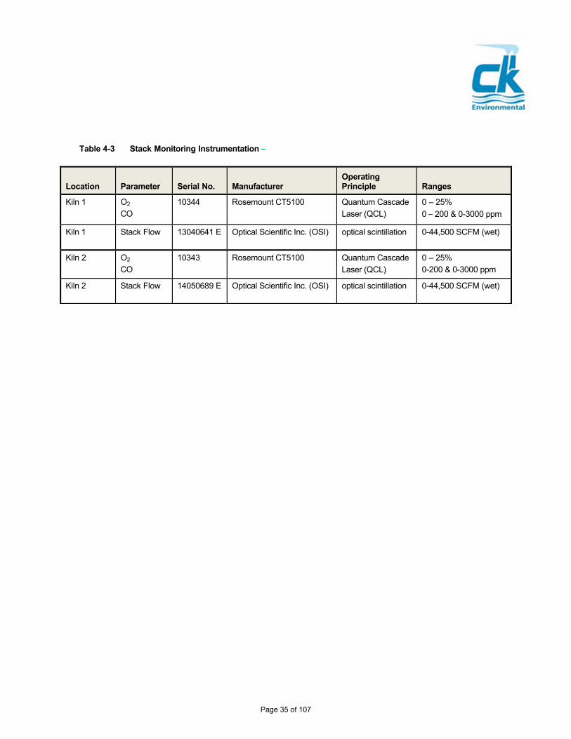
Table 4-3 Stack Monitoring Instrumentation –
Location
Parameter
Serial No.
Manufacturer
Operating Principle
Ranges
Kiln 1 O2
CO
10344 Rosemount CT5100 Quantum Cascade
Laser (QCL)
0 – 25%
0 – 200 & 0-3000 ppm
Kiln 1 Stack Flow 13040641 E Optical Scientific Inc. (OSI) optical scintillation 0-44,500 SCFM (wet)
Kiln 2 O2
CO
10343 Rosemount CT5100 Quantum Cascade
Laser (QCL)
0 – 25%
0-200 & 0-3000 ppm
Kiln 2 Stack Flow 14050689 E Optical Scientific Inc. (OSI) optical scintillation 0-44,500 SCFM (wet)
Page 35 of 107

5.0 Test Program Operations
This section provides an overview of test program design, planned kiln operating conditions, planned waste feed requirements, overall sampling strategy and anticipated test schedule.
5.1 Test Program Rationale
This CPT program has been designed to re-establish compliance with all applicable MACT emission standards as previously described in Table 1-2. Two (2) LWAK operating conditions are planned for this test program. The planned operating conditions will be representative of stressed operations at the facility and will be conducted using reasonable worst case waste materials and fuels, including waste fortification for the purposes of establishing appropriate metal feed rate limits as outlined subsequently in this section.
Detailed information on the sampling and analytical methods to be followed for the program along with other information related to the field test program procedures and analytical protocols is provided in Section 6.0 (Sampling and Analytical Program) and Appendix A (Quality Assurance Project Plan).
5.1.1 Demonstrate Compliance with Performance Standards
The test program will feature a comprehensive set of emission measurements to demonstrate compliance with the applicable performance standards listed previously in Table 1-2.
5.1.2 Sampling Strategy
The overall testing strategy has been developed to provide the data needed to demonstrate compliance with the applicable MACT emission standards. Each LWAK is equipped with a stack sampling arrangement consisting of four or more ports at each of two elevations (sampling platforms), with each port oriented at a 90-degree separation from the others. This arrangement is more than sufficient to allow for all planned sampling to be completed concurrently.
Each LWAK is also equipped with sampling ports prior to the air pollution control system (inlet sampling ports). Each inlet sampling location consists of two ports oriented at a 90-degree separation from the other.
The length of each sampling run will be determined by the need to collect sufficient sample volume to obtain adequate detection limits. Expected sample train run times are described more completely in Section 6.0 (Sampling and Analysis Program) and Appendix A (QAPP) of this document.
5.1.3 Dealing with Potential Process Interruptions
If there is a waste feed interruption (i.e., AWFCO) during a sampling run, the following guidelines are suggested and will only be implemented with NYSDEC consultation and concurrence:
Sampling will be stopped as quickly as possible after the interruption.
If the interruption is less than 30 minutes, there will be a 15-minute line out period, and then sampling will recommence.
If the interruption is between 30 and 60 minutes, there will be a 30-minute line out period and then sampling will recommence.
If the interruption exceeds 60 minutes, there will be a one-hour line out period before testing is resumed.
Page 36 of 107

If the interruption lasts more than 60 minutes and there is little hope of completing the day’s
run, then the run will be aborted and repeated at later time. 5.2 Planned Test Conditions
For this program, two (2) test conditions will be conducted to confirm compliance with the MACT standards. The operating conditions for the test are based on a review of prior operating data, experience operating under the current set of OPLs. The operating conditions described below will be performed in the order listed.
Test Condition 1 will establish new operating limits for LLGF feed rate, waste feed atomization pressure, shale production rate, kiln back-end temperature and GCT exit temperature. During Condition 1, testing will be performed for PCDDs/PCDFs. Determination of the destruction and removal efficiency (DRE) of one or more principal organic hazardous constituents (POHCs) as required by the standards listed in 40 CFR Part 63.1221(c) will be conducted during test condition 1.
Test Condition 2 will establish new operating limits for shale production rate, baghouse inlet temperature, total metals feed rates, total chlorine feed rate, dry sorbent feed rate and dry sorbent carrier fluid flow rate, GSA and baghouse lime feed rates. During Condition 2, testing will be performed for metals, PM and HCl/Cl2.
An overview of planned test conditions along with target operating ranges is provided in Table 5-1.
Each kiln will be operated under reasonable worst-case conditions to generate higher than normal emissions to demonstrate that even under stressed conditions, the kiln’s emissions are below the regulatory limits. Pursuant to 40 CFR 63.1207(g)(1), chlorine content in the LLGF will be normal or higher during the PCDD/PCDF test runs (Test Condition 1). Based on fuel data from calendar year 2018, Norlite will ensure that the chlorine concentration (measured as total halogens) will be approximately 1.5 percent on a weight basis. Ash content will be normal or higher during the semi-volatile metal and low volatile metals test runs (Test Condition 2). Based on fuel data from calendar year 2018, Norlite will ensure that the ash concentration will be approximately 1.7 percent on a weight basis. The chlorine and ash content results will be reported with the fuel analysis in the test report. The baghouse pulse cycle will be maintained at its normal rate throughout the particulate matter, semivolatile metals and low volatile metals test runs (Test Condition 2). The baghouse pulse cycle will be included with the operational data in the test report.
5.3 Description, Preparation and Delivery of CPT Feed Materials
To the extent practicable (and except for the added constituents subsequently noted), reasonable worst-case materials processed at the facility will be fed to the kiln during the test program. Pumpable waste materials will be stockpiled in appropriate feed tanks to meet the objectives for the target parameters. All waste materials will be delivered to the kiln in accordance with routine operation and currently permitted procedures as described elsewhere in this document.
Page 37 of 107

Table 5-1 Target Operating Parameters for the 2020 CPT a
a - Values listed are targets and may vary by ± 20% during actual testing. Note that values are only listed for the condition during which they will be re-established.
5.4 Test Materials and Quantities
5.4.1 Quantity of Hazardous Waste to be Burned
The quantity of hazardous waste (LLGF) to be burned during this program is based on the target feed rate specified in Table 5-1. Assuming about 15 hours of waste burning over each day, and the planned schedule outlined later in this section, it is estimated that about 26,000 gallons of LLGF will be burned during the test program.
5.4.2 Time to Achieve Steady-State Operation
The time required to reach steady-state operation is governed primarily by the time to establish acceptable rolling averages for the applicable process parameters. HRAs for all applicable parameters will be established at or near their desired values prior to test initiation. One-hour of steady state operation will be required to establish desired HRAs prior to test initiation. If emission sampling must be interrupted during the middle of a run, the one-minute averages during the interruptions will not be used for the calculations of HRAs following the interruption. The last HRA considered will be concurrent with the end of the test run sampling period.
Process Parameter Units Condition 1 Condition 2
Maximum LLGF Feed Rate gpm 10.5
Minimum LLGF Feed Atomization P
psig 56.4
Maximum Shale Feed Rate tph 24.7 24.7
Maximum Total Chlorine Feed Rate lb/hr 96.8
Maximum Total Mercury Feed Rate lb/hr 0.010
Maximum Total LVM Feed Rate lb/hr 11.0
Maximum Total Pumpable LVM Feed Rate lb/hr 3.72
Maximum Total SVM Feed Rate lb/hr 11.1
Minimum Kiln Back-End Temperature F 866
Maximum GCT Exit Temperature F 453
Minimum Total Baghouse / GSA Lime Feed Rate
lb/hr 209
Minimum Total Baghouse / GSA Carrier Fluid Flow Rate
cfm 180
Maximum Baghouse Inlet Temperature F 400
Page 38 of 107

5.5 Waste Feed Fortification
In order to establish appropriate metals feed rate limits, and to demonstrate the required performance criteria for DRE it will be necessary to fortify (augment) the hazardous waste fuel (LLGF) with various constituents.
5.5.1 Metals Constituent Additions
To demonstrate the required performance criteria for metals control, it will be necessary to fortify (augment) the LWAK fuel (LLGF) with inorganic constituents. This section describes the selected constituents and relevant parameters pertaining to waste feed fortification.
5.5.1.1 Waste Feed Strategy
Norlite intends to fortify the LLGF with several metal constituents for the purposes of establishing desired metal feed rates and demonstrating satisfactory metals removal from the system. Norlite plans to add solutions of metal acetates to the LLGF feed tanks (if necessary) to achieve the desired feed concentrations.
Norlite plans to use cadmium acetate, chromic acetate and mercuric acetate to fortify the LLGF used in the test. These organometallic compounds were chosen due to their solubility in alcohol which is a major component of the LLGF.
5.5.1.2 Metal Feed Rate
The goal for the CPT will be to establish feed rate limits for metals consistent with current permit levels. The ultimate objective will be to use the SREs demonstrated during the CPT for mercury, chromium (representing the LVM group) and cadmium (representing the SVM group) to arrive at feed rate limits that meet the appropriate emission standard.
Justification for the selection of surrogate metals comes from the MACT rule itself and has been supported in EPA Regions 4 and 5. In the MACT preamble (pg 52946), EPA provides discussion on the issue of metal surrogates and states in the 3rd column, 2nd paragraph that “For example, you may use chromium as a surrogate during the performance test for all low volatile metals. Similarly, you may use lead as a surrogate for cadmium, the other semi-volatile metal. This is because the metals within a volatility group have generally the same volatility.” (EPA also goes on to say that you could also use one SVM as a surrogate for any LVM because SVM will be more difficult to control.)
As stated above, it is expected that any metals added to the LLGF feed tank will be in the form of metal acetates. An example feed rate calculation is presented in Table 5-2. This feed rate represents the limit for arsenic, beryllium and chromium combined. These calculations assume that the minimum SRE required to comply with the MACT LVM standard of 110 g/m3 is 99.85%. Following the CPT Norlite will set significantly lower actual feed rates in the NOC based on actual SRE.
Page 39 of 107

Table 5-2 Metals Feed Rate – Example Calculations
Parameter LVM SVM
Surrogate Metal Chromium Cadmium
MACT standard, µg/m³ @ 7% O2 110 250
Assumed SRE (%) 99.85% 99.85%
Assumed Stack Flow rate (dscfm) 33,800 33,800
Assumed Stack Oxygen (%) 15.0 15.0
Maximum Emission Rate (lbs/hr) 0.0060 0.0136
Maximum CPT Feed Rate (lb/hr) 4.0 9.0
5.5.2 POHC DRE
Principal organic hazardous constituent (POHC) DRE will be demonstrated during Condition 1. Since there is not a POHC present in the native waste at a sufficient concentration to enable detection following high levels of destruction in the kiln, fortification of the waste stream is necessary. Monochlorobenzene (MCB) will be used to fortify the LLGF feed stream. B3 Systems of Raleigh, NC has been retained to supply the MCB material and to spike the material into the kiln. The target MCB injection rate was 75 lb/hr for each of the three test runs.
5.6 Test Schedule
This section summarizes the anticipated schedule for test program implementation. Table 5-3 provides an anticipated schedule associated with the day-to-day activities of the CPT field program. This schedule includes days for arrival, safety orientation and testing and assumes that testing will be conducted over the course of three days per unit.
Given that testing is planned for several long days, during the test setup day, Norlite, NYSDEC and the CK field team leader will develop a consensus regarding the latest time that a run will be started for the planned test day.
Table 5-3 Anticipated CPT Field Schedule (per unit) Day
Arrival onsite, site safety training and equipment set-up. Also conduct preliminary stack measurements.
1
Test Condition 1, Runs C1-R1 and C1-R2 2
Test Condition 1, Run C1-R3 3
Test Condition 2, Runs C2-R1, C2-R2 and C2-R3 4
Ship samples. Pack equipment and depart site. 5
Page 40 of 107

6.0 Sampling and Analysis Program Overview This section presents a summary of the sampling and analysis program for this project. Further details on the overall sampling and analysis program are found in the QAPP for this project, located in Appendix A. As noted in previous sections of this document, the test program will consist of two test conditions consisting of three (3) sampling runs each per kiln. 6.1 Liquid Waste Sampling and Analysis
The LWAKs burn a single liquid hazardous waste feed stream that will be sampled prior to being fed to the kiln in accordance with acceptable protocols. A sampling tap in the feed line is available for this purpose. The LLGF will be sampled every 15 minutes during each run, composited and analyzed for the parameters listed in Table 6-1.
Facility personnel will collect these samples under CK's direction using pre-cleaned sample bottles suitable for the type of sample being collected and the intended analysis. CK will provide all sample containers for stack samples and assume custody of the samples at the end of each day. Norlite will provide sample containers supplied by AES for all feed stream analysis samples. Prior to initiating field-testing activities, CK and Norlite will hold a training session with facility staff responsible for sample collection to review grab sampling techniques, size of sample aliquots, compositing procedures, and sample bottles to be used. Agency personnel who will be providing testing oversight are invited to attend this training session. Any agency required split samples should be announced at this time and containers provided by Agency personnel.
6.2 Used Oil Sampling and Analysis
It is not anticipated that used oil will be fed to the kiln during the test. However, should this not be the case, used oil will be sampled at the same frequency and analyzed for the same parameters as the LLGF.
6.3 Shale Sampling and Analysis
Raw shale fed to the kiln will be sampled at the beginning, middle and end of each run from the conveyor belt using a scoop with an appropriate aliquot being emptied into the final collection bottle. Shale will be analyzed using the methods and procedures identified in Table 6-1.
Page 41 of 107
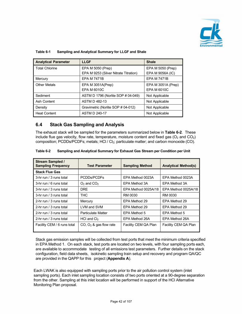
Table 6-1 Sampling and Analytical Summary for LLGF and Shale
Analytical Parameter LLGF Shale
Total Chlorine EPA M 5050 (Prep) EPA M 9253 (Silver Nitrate Titration)
EPA M 5050 (Prep) EPA M 9056A (IC)
Mercury EPA M 7471B EPA M 7471B
Other Metals EPA M 3051A(Prep) EPA M 6010C
EPA M 3051A (Prep) EPA M 6010C
Sediment ASTM D 1796 (Norlite SOP # 04-049) Not Applicable
Ash Content ASTM D 482-13 Not Applicable
Density Gravimetric (Norlite SOP # 04-012) Not Applicable
Heat Content ASTM D 240-17 Not Applicable
6.4 Stack Gas Sampling and Analysis
The exhaust stack will be sampled for the parameters summarized below in Table 6-2. These include flue gas velocity, flow rate, temperature, moisture content and fixed gas (O2 and CO2) composition; PCDDs/PCDFs; metals; HCl / Cl2; particulate matter; and carbon monoxide (CO).
Table 6-2 Sampling and Analytical Summary for Exhaust Gas Stream per Condition per Unit
Stream Sampled / Sampling Frequency
Test Parameter
Sampling Method
Analytical Method(s)
Stack Flue Gas 3-hr run / 3 runs total PCDDs/PCDFs EPA Method 0023A EPA Method 0023A
3-hr run / 6 runs total O2 and CO2 EPA Method 3A EPA Method 3A
3-hr run / 3 runs total DRE EPA Method 0025A/18 EPA Method 0025A/18
3-hr run / 3 runs total THC RM 0030 RM 0030
2-hr run / 3 runs total Mercury EPA Method 29 EPA Method 29
2-hr run / 3 runs total LVM and SVM EPA Method 29 EPA Method 29
2-hr run / 3 runs total Particulate Matter EPA Method 5 EPA Method 5
2-hr run / 3 runs total HCl and Cl2 EPA Method 26A EPA Method 26A
Facility CEM / 6 runs total CO, O2 & gas flow rate Facility CEM QA Plan Facility CEM QA Plan
Stack gas emission samples will be collected from test ports that meet the minimum criteria specified in EPA Method 1. On each stack, test ports are located on two levels, with four sampling ports each, are available to accommodate testing of all emissions test parameters. Further details on the stack configuration, field data sheets, isokinetic sampling train setup and recovery and program QA/QC are provided in the QAPP for this project (Appendix A).
Each LWAK is also equipped with sampling ports prior to the air pollution control system (inlet sampling ports). Each inlet sampling location consists of two ports oriented at a 90-degree separation from the other. Sampling at this inlet location will be performed in support of the HCl Alternative Monitoring Plan proposal.
Page 42 of 107

Gas stream flow rate and moisture will be determined during each test run in conjunction with each isokinetic sampling train. Gas stream velocity will be determined using a pitot tube and water manometer in accordance with EPA Method 2. Gas stream temperature will also be determined at each of the Method 2 traverse points using a Type K thermocouple and pyrometer. Gas stream moisture will be determined as specified in EPA Method 4 concurrent with each isokinetic sampling method. In this procedure the impinger contents are measured for volume or weighed before and after each test run and used in conjunction with the metered gas volume to determine the gas stream moisture content.
Page 43 of 107

7.0 Final Data Reporting
The final report for this project will be a comprehensive data compilation that properly and logically documents and certifies all required test results. The report will include all the required elements of a MACT NOC as outlined in Table 7-1 below.
Table 7-1 Types of Information to be presented in Norlite’s NOC
Facility Information
Facility Name and Location: Norlite LLC, Cohoes, NY 12047
Contact: Prince Knight –(518)- 235-0401, Ext 4049 – [email protected]
Source Information
Title V Classification: Major Source
Affected Sources: Lightweight Aggregate Kilns 1 and 2
Air Pollution Control: Cyclone, GCT, GSA and fabric filter
Applicability
The kilns are regulated under 40 CFR Part 63 Subpart EEE (HWC MACT) as lightweight aggregate kilns
Emission Standards
The applicable emission standards (listed in Table 1-1 of this CPT Plan) for the Norlite facility are based on the limits outlined at 40 CFR 63.1221 for lightweight aggregate kilns. All emission standards (except DRE) are corrected to 7% oxygen.
Compliance Demonstrations
Once the CPT has been completed, Norlite will summarize the test results and show that all emission standards were met and that all operating limits were satisfied.
Certification
Norlite LLC hereby certifies that:
All required CEMS and CMS are installed, calibrated and continuously operating in compliance with the requirements of Subpart EEE;
Based on the results of the CPT conducted in [DATE], the LWAKs are operating in compliance with the emission standards and operating requirements of 40 CFR Part 63 Subpart EEE, and the OPLs required by 40 CFR 63.1209 established during this CPT ensure continued compliance with the standards.
Signature:
Name:
Title: Date:
Page 44 of 107

CK plans to follow the generic guidance provided by EPA for CPT report preparation. The report will be structured in a similar manner with sections delineated as follows:
Summary of Test Results and Comparison to MACT Standards
Report Certification
Introduction and Overview of Process Description
Process Operating Conditions During the CPT
Kiln Feed Stream and Stack Sampling Test Results
Quality Assurance / Quality Control Documentation
Report appendices will also provide detailed supporting documentation and would include:
Process Operating Data
Field Data Sheets and Sampling Documentation
Analytical Data Reports
CMS / CEMS performance Evaluation Test Evaluation Results
This report will be submitted concurrent with NOC. Further details on data reporting are provided in Section 13.0 of the QAPP (Appendix A).
Page 45 of 107

8.0 Health and Safety 8.1 Plant Access and Sampling Location Access
Visitors at Norlite are required to sign at the entry gate and will go through a site-specific orientation. Non office visitors are expected to have basic personal protective equipment (PPE) eye protection, safety footwear, head protection, hand protection, and hearing protection for site walks. Visitors will be escorted during their visit to designated work areas and visitors are not allowed to wander to undesignated areas. Visitors that require facility walk downs will be escorted during the entire duration of the visit.
8.2 Sampling Location Safety
8.2.1 Field Safety Responsibilities
A Safe Work Plan (SWP) will be developed by CK Project Manager before the start of the test program identifying potential hazards, emergency procedures, roles, and responsibilities, required training and task hazard assessment.
The CK PM is, by designation, the individual who has the primary responsibility for ensuring the health and safety of CK employees during this test program. CK Project Team Leader on site is responsible for the implementation of safety procedures in the field. Field Team Leader will ensure that field staff has necessary PPE not limiting to eye protection, safety footwear, head protection, hearing protection, hand protection and fall protection equipment.
Access to the primary sampling location is via stairs and the sampling platform is a Mine Safety and Health Administration (MSHA) approved platform. Access to a secondary sampling level is made via a caged ladder. If this sampling platform is used, CK sampling equipment will be hoisted with a rope and pulley setup. Necessary precautions will be taken by barricading the drop area under the sampling platform with caution tape.
Safety concerns that may arise before or during the sampling process will be accessed and mitigated using hierarchy of controls before the work is resumed.
Page 46 of 107

Appendix A
Quality Assurance Project Plan (QAPP)
Page 47 of 107

Quality Assurance Project PlanNorlite, LLC – Cohoes, NY MACT CPT Plan
1
Quality Assurance Project Plan (QAPP)
MACT CPT Program
Norlite LWAK No. 1 & 2
This document presents the Quality Assurance and Quality Control goals, objectives, and procedures for the Norlite comprehensive performance test (CPT) program to be conducted beginning the week of September 21, 2020. The quality assurance/quality control procedures and criteria for this program will comply with the requirements of this document and any updates. The analytical work conducted will incorporate the QA/QC requirements of the approved methods. This document has been prepared using available guidance provided in the following documents:
"Component 2 - How to Review a Quality Assurance Project Plan (including Attachment A - Generic Trial Burn QAPP", Hazardous Waste Combustion Unit Permitting Manual, U.S. EPA Region 6, January 1998.
"Handbook – Quality Assurance/Quality Control (QA/QC) Procedures for Hazardous Waste Incineration” (EPA/625/6-89/023 January 1990).
Facility ID Number: NYD 080 469 935
Prepared for: Norlite LLC, Cohoes, NY
Prepared by: CK Environmental Inc., Canton, MA 02021
Revision No.: 1
Date of Rev 1 Submittal: July 10, 2020
Expected Test Start Date: September 22, 2020
Page 48 of 107

Quality Assurance Project PlanNorlite, LLC – Cohoes, NY MACT CPT Plan
:
Project Approvals _______________________________
David Maguffin, Plant Manager Date Norlite
2/13/20202
_______________________________________ ___________________________ Kevin J. Kelley, QSTI Project Manager Date CK Environmental
Tara Daniels, Laboratory Coordinator Date Adirondack Environmental Services
Douglas Czachor, Laboratory Coordinator Date Norlite
2020/02/12
Salima Haniff, Quality Assurance Manager Date Bureau Veritas Laboratories
Page 49 of 107

Quality Assurance Project PlanNorlite, LLC – Cohoes, NY MACT CPT Plan
:
Contents 1.0 PROJECT DESCRIPTION .................................................................................................................. 54
2.0
PROJECT ORGANIZATION ............................................................................................................... 55 2.1 Facility Owner / Operator: Norlite, LLC .............................................................................................. 55 2.2 CK QA Officer ....................................................................................................................................... 55
2.3 Regulatory Oversight ........................................................................................................................... 55 2.4 Laboratory Services Coordinators ....................................................................................................... 55
3.0
DATA QUALITY OBJECTIVES.......................................................................................................... 56 3.1 Precision, Accuracy and Completeness ............................................................................................. 56 3.2 Representativeness and Comparability .............................................................................................. 57 3.3 Data Usability and Detection Limit Considerations ............................................................................ 57
4.0
SAMPLING AND MONITORING PROCEDURES ............................................................................ 59
4.1
4.2
Kiln Feed Materials Sample Collection ............................................................................................... 594.1.1 Sampling Locations ................................................................................................................. 594.1.2 Sampling Procedures .............................................................................................................. 59Stack Emission Measurements ........................................................................................................... 604.2.1 Sampling Location ....................................................................................................................61 4.2.2 Gas Stream Velocity and Moisture ..........................................................................................61 4.2.3 PCDDs / PCDFs .......................................................................................................................63 4.2.4 Metals .................................................................................................................................... 63 4.2.5 PM and HCl / Cl2 .......................................................................................................................64 4.2.6 Continuous Emission Monitoring – CK ....................................................................................64 4.2.7 Continuous Emission Monitoring – Norlite ..............................................................................64
5.0 SAMPLE CUSTODY ............................................................................................................................66
5.1 Field Sampling Operations ...................................................................................................................66 5.1.1 Glassware Preparation .............................................................................................................66 5.1.2 Sample Labels and Sampling Checklists ................................................................................66 5.1.3 Preliminary Measurements ......................................................................................................68 5.1.4 Field Documentation ................................................................................................................68
5.2 Field Laboratory Operations .................................................................................................................68 5.2.1 Sample Media Preparation .......................................................................................................68 5.2.2 Field Laboratory Facility ...........................................................................................................68 5.2.3 Sample Storage ........................................................................................................................69 5.2.4 Sample Shipment .....................................................................................................................69
5.2.5 Sample Preservation and Holding Times ........................................................................ 69
Page 50 of 107

Quality Assurance Project PlanNorlite, LLC – Cohoes, NY MACT CPT Plan
6.0
FIELD EQUIPMENT CALIBRATION PROCEDURES AND FREQUENCY .................................... 70
7.0
ANALYTICAL METHODS AND PROCEDURES .............................................................................. 72
7.1 Analysis of Kiln Feed Materials ........................................................................................................... 74 7.2 Analysis of Stack Gas Samples ........................................................................................................... 76
7.2.1 PCDDs / PCDFs in Stack Gas Samples ............................................................................. 76 7.2.2 Metals in Stack Gas Samples ................................................................................................ 80 7.2.3 Hydrogen Chloride and Chlorine in Stack Gas Samples ...................................................... 81 7.2.4 Particulate Matter in Stack Gas Samples .............................................................................. 82 7.2.5 VOCs in Stack Gas Samples ………………………………………………………………..82
8.0 QUALITY CONTROL PROCEDURES .............................................................................................. 83
8.1 Field Sampling QC Procedures .......................................................................................................... 83 8.1.1 Equipment Inspection, Maintenance and Calibration ........................................................... 83 8.1.2 Sampling Equipment QC Checks and Frequency ................................................................ 83
8.2 Analytical QC Procedures ............................................................................................................... 84 8.2.1 Quality Control Samples and Blanks ..................................................................................... 84
9.0 PERFORMANCE AND SYSTEM AUDITS ....................................................................................... 86
10.0 PREVENTIVE MAINTENANCE ......................................................................................................... 87
10.1 Field Sampling Equipment .................................................................................................................. 87 10.2 Facility Equipment and Instrumentation ............................................................................................. 87
11.0 PROCEDURES USED TO ASSESS DATA PRECISION AND ACCURACY ................................ 88
11.1 Accuracy .............................................................................................................................................. 88 11.2 Precision .................................................................................................................................................. 88 11.3 Completeness ............................................................................................................................................. 89
12.0 CORRECTIVE ACTIONS ................................................................................................................... 90
12.1 Immediate Corrective Action ............................................................................................................... 90 12.2 Long-Term Corrective Action .............................................................................................................. 90
13.0 DATA REDUCTION, VALIDATION AND DATA REPORTING ...................................................... 92
13.1 Field Data Reduction ............................................................................................................................92 13.2 Laboratory Data Reduction ...................................................................................................................92
Page 51 of 107

Quality Assurance Project PlanNorlite, LLC – Cohoes, NY MACT CPT Plan
13.3 Data Validation ......................................................................................................................................93 13.4 Data Reporting ......................................................................................................................................94
13.4.1 Preliminary Data Reporting in the Field ................................................................................. 94 13.4.2 Preliminary Reporting of Results .............................................................................................94 13.4.3 Final Data Report ......................................................................................................................94 13.4.4 Management of Non-Detects ...................................................................................................95 13.4.5 Oxygen Correction ....................................................................................................................95 13.4.6 Sampling Times and Calculation of Results ............................................................................95 13.4.7 Blank Correction .......................................................................................................................95 13.4.8 Rounding and Significant Figures ......................................................................................... 95 13.4.9 Evaluating Compliance ...................................................................................................... 96
14.0 QUALITY ASSURANCE REPORTS ................................................................................................. 97
14.1 Internal Reports ................................................................................................................................... 97 14.2 Reports to Client .................................................................................................................................. 97 14.3 Regulatory Agency Notifications ........................................................................................................ 97
ATTACHMENTS
Attachment A – Example Field Data Sheets
Attachment B – Isokinetic Sample Train Schematics
List of Tables
Table 3-1 Precision, Accuracy and Completeness Objectives .......................................................... 57
Table 4-1 Sampling and Analysis Summary for Kiln Feed Materials ................................................. 60
Table 4-2 Overview of Stack Emission Measurement Program ........................................................ 61
Table 5-1 Sample Preservation and Holding Time Requirements ..................................................... 69
Table 7-1 Detailed Overview of Sampling and Analysis Program ....................................................... 73
Table 7-2 Sampling and Analytical Summary for LLGF and Shale ................................................... 74
Table 7-3 QA/QC Procedures for Total Chlorine in Kiln Feed Materials ........................................... 74
Table 7-4 QA/QC Procedures for Metals in Kiln Feed Materials ........................................................ 75
Table 7-5 Standard Spiking Requirements for Method 0023A .......................................................... 78
Table 7-6 QA Objectives for PCDD/PCDF Analysis of Stack Gas Samples ..................................... 79
Table 7-7 QA Requirements for Metals in Stack Gas by ICP-MS and CVAAS ................................ 81
Table 7-8 QA Requirements for Chlorides in Stack Gas ................................................................... 82
Page 52 of 107

Quality Assurance Project PlanNorlite, LLC – Cohoes, NY MACT CPT Plan
Figures
Figure 4-1 Stack Sampling Traverse Point Locations ............................................................................. 62
Figure 5-1 Sample Packing List and Sample Label ................................................................................ 67
Page 53 of 107

Quality Assurance Project PlanNorlite, LLC – Cohoes, NY MACT CPT Plan
1.0 Project Description
This project will consist of a comprehensive sampling and analysis program designed to re-certify compliance with all applicable MACT (Subpart EEE) performance standards on Kiln 1 and 2 following installation and start-up of new APC systems. Testing will be performed under two (2) operating conditions, per kiln, comprised of three (3) sampling runs per condition. The reader is referred to other sections of the overall CPT Plan for further details on program scope, test objectives and target parameters for emission measurements and process monitoring. The remainder of this QAPP outlines the detailed measures that will be followed to ensure collection of valid data.
Page 54 of 107

Quality Assurance Project PlanNorlite, LLC – Cohoes, NY MACT CPT Plan
2.0 Project Organization CK Environmental (CK) will be responsible for overall management of this MACT CPT program. The CK Project Manager, Mr. Kevin Kelley, will provide overall direction of the program and will report to the Norlite Project Manager, Mr. Prince Knight. As project manager, Mr. Kelley will be responsible for project design and implementation, communicating with the client and scheduling all activities.
2.1 Facility Owner / Operator: Norlite, LLC
Mr. Prince Knight is the Environmental & Regulatory Compliance Manager at Norlite and is the Norlite project manager for the CPT program. Mr. Knight will be responsible for coordinating Norlite’s efforts during the program and will be the principal point of contact during implementation of the field test program. Mr. Knight will be assisted by Operations in waste feed stream sampling and process data retrieval.
2.2 QA Officer
Mr. Kevin Kelley will also serve as the project Quality Assurance Officer (QAO) and will be responsible for review and approval of this QAPP, as well as any subsequent revisions. He will monitor implementation of field and laboratory activities and schedule performance and/or system audits as discussed later in Section 9.0. The QAO will report on any conditions noted which may adversely affect data quality.
Mr. Mike Kelley will provide oversight of the CK field measurement team functions including field sampling, data verification and data quality assessment activities and will prepare a section of the Final Report summarizing QA/QC activities and providing an overall evaluation of data quality.
2.3 Regulatory Oversight
The New York State Department of Environmental Conservation (NYSDEC) and EPA Region 2 will be the primary Agencies involved in review and approval of this QAPP.
CK will obtain commercially available audit samples for Method 26A and Method 29 from accredited audit sample provider Environmental Resource Associates located in Golden, CO for the measurement program. The test consists of blind audit samples provided by the accredited audit sample provider are evaluated during the performance test program and analyzed by the same laboratory following the same procedures as the compliance samples. Per the audit program, the results of these audits will be supplied to the NYSDEC.
2.4 Laboratory Services Coordinators
Bureau Veritas Laboratories (BV) will perform all emission sample analyses. Marinela Sim will serve as the laboratory services coordinator (LSC), who will be the principal point of contact for the CK Management Team. The LSC will review QA requirements with all laboratory staff to ensure that all required measures are taken to meet data quality objectives. They will monitor the shipment and receipt of samples, track analytical progress and review data as reported from the laboratories for completeness. Ms. Tara Daniels will serve as the LSC for Adirondack Environmental Services (AES). AES will perform kiln feed and fuel analyses for this program. Mr. Douglas Czachor will serve as the LSC for Norlite’s in house laboratory and will coordinate sample deliveries to AES and be the main liaison between AES and Norlite. Each LSC will be responsible for validation of all data generated by the laboratory for this program and will provide all necessary documentation for inclusion in the final report.
Page 55 of 107

Quality Assurance Project PlanNorlite, LLC – Cohoes, NY MACT CPT Plan
3.0 Data Quality Objectives
This section provides a general overview of the data quality objectives (DQOs) for this test program. Specific DQOs for each individual sampling train and/or each analytical methodology performed by the subcontractor laboratories are provided later in Section 7.0 of this QAPP.
3.1 Precision, Accuracy and Completeness
The collection of data to fully characterize the LWAK waste feed material and stack gas emissions requires that sampling and analysis procedures be conducted with properly operated and calibrated equipment by trained personnel. The overall program has been designed with consideration of sampling parameters and analytical limits to ensure that the achieved method-specific detection limits for measured emissions will be more than adequate for demonstrating compliance with the MACT emission standards and performance criteria. Table 3-1 provides a summary of the overall precision, accuracy and completeness objectives for the program.
Precision is defined as a measurement of mutual agreement among individual measurements made under prescribed similar conditions. Precision is expressed in terms of relative percent difference (RPD) between duplicate determinations and in terms of relative standard deviation (RSD) when 3 or more determinations are made. Overall precision for analysis of the waste feed streams will be assessed through the analysis of one set of duplicate samples for each designated parameter.
Accuracy is the degree of agreement of a measurement with an accepted reference or true value. Analytical accuracy will be measured through the recoveries of surrogate spikes, matrix spikes, analysis of standard reference materials or audit sample analysis. Surrogates are compounds added to samples submitted for organic analyses prior to extraction and analysis; their recoveries are measured to assess sample-specific analytical efficiency and accuracy. Matrix spike (MS) samples for the waste feed will be prepared by spiking known amounts of target analytes into a portion of the sample. Matrix spike samples for the stack organic analyses will be prepared by spiking known amounts of target analytes into the sampling media and then carrying the spiked sample through the entire preparation and analysis sequence. Recoveries are monitored to assess laboratory and method accuracy. LCS will also be used to distinguish between method performance and matrix effects on accuracy. LCS and MS solutions will be independent from calibration standards.
Completeness is a measure of the amount of valid data obtained compared to the amount that was expected under normal conditions. The overall program objective is to obtain valid data for three (3) runs for each test condition. For all data considered critical to the investigation, a completeness objective of 100% has been established. As a result, critical priority data from each set of three (3) runs should achieve the precision and accuracy goals established herein. This completeness criterion applies to all permit parameters in emissions samples as well as any feed/process stream samples. Individual samples for which the critical data points do not achieve accuracy and/or precision data quality objectives may require reanalysis. Results for samples where matrix interferences preclude meeting objectives for the recoveries of surrogates or spikes will be evaluated for potential bias to calculated emission results. In summary, the completeness goals are stated at 100% since a minimum of three valid runs is necessary to assess operation at each test condition.
Page 56 of 107

Quality Assurance Project PlanNorlite, LLC – Cohoes, NY MACT CPT Plan
Table 3-1 Precision, Accuracy and Completeness Objectives
Stream Sampled / Sampling Method
Parameter Sampling Precision
(RPD)
Analytical Precision
(RPD)
Analytical Accuracy (%)
Completeness (%)
Kiln Feed Materials
Grab / Composite Ash Content < 50 < 35 75 -125 85
Grab / Composite Density < 50 < 35 75 -125 85
Grab / Composite Heat Content < 50 < 35 75 -125 85
Grab / Composite Total Chlorides < 50 < 10 75 -125 85
Grab / Composite Metals (a) < 50 < 35 75 -125 85
Stack Flue Gas
EPA Method 0023A PCDDs/PCDFs (b) see Table 7-6 see Table 7-6 100
EPA Methods 5 PM (b) ±0.5 mg ±0.1 mg 100
EPA Methods 26A HCl/Cl2 (b) see Table 7-6 see Table 7-6 100
EPA Method 29 Metals (a) (b) see Table 7-4 see Table 7-4 100
Facility CEMS CO and O2 (b) ± 3% span ± 3% span 100
EPA Method 3/3A CO2 and O2 (b) 0.5% 0.5% 100
Method 0030 VOC (b) 0.1 ug/M3 0.1 ug/M3 100
EPA Method 25A/18 VOC (b) ± 2% span ± 2% span 100
(a) Target metals in the LLGF include arsenic, beryllium, cadmium, chromium, lead and mercury (MACT).
(b) Precision not determinable for stack gas sampling since co-located sampling trains will not be used.
Note: This table represents an overall summary of the QA objectives for this project. Please refer to the method-specific QA summary
tables in Section 7.0 of this QAPP.
3.2 Representativeness and Comparability
It is recognized that the usefulness of the data is also contingent upon meeting the criteria for representativeness and comparability. Wherever possible, reference methods and standard sampling procedures will be used. The QA objective is that all measurements be representative of the matrix and operation being evaluated. The detailed requirements for sampling given in the various EPA Reference Methods will be followed to ensure representative sampling of flue gases. The grab/composite sampling regimen for the kiln feed stream during each test run will also provide representative samples of this matrix.
The corresponding QA objective is that all data resulting from sampling and analysis be comparable with other representative measurements made by the field sampling team, on this or a similar process operating under similar conditions. The use of published sampling and analytical methods and standard reporting units will aid in ensuring the comparability of the data.
3.3 Data Usability and Detection Limit Considerations
CK and each of the subcontract laboratories on this program are aware of the requirement that all data generated for a program of this nature are of high quality and that detection limits reported are usable for
Page 57 of 107

Quality Assurance Project PlanNorlite, LLC – Cohoes, NY MACT CPT Plan
compliance assessment purposes. We have reviewed the relevant EPA Region 2 guidance on this issue and believe that the data to be generated for this program will meet or exceed EPA’s goals based on our past
Page 58 of 107

Quality Assurance Project PlanNorlite, LLC – Cohoes, NY MACT CPT Plan
experience with each specific laboratory on past similar programs. All the laboratories to be used on this program follow 40 CFR Part 136, Appendix A for the determination of method-specific method detection limits (MDLs) for the various analytes to be measured in this program. However, for the purposes of data reporting for this program, method specific reporting limits (RLs) will be used wherever a sample is determined to be below detection. Two categories of such RLs is envisioned for this project:
Waste Feed Samples – RLs for metals and total chlorides in the LLGF samples will be specific to the
actual waste matrix. In the absence of actual detected values, the full value of the RL will be used in performing any required calculations pertaining to compliance with feed rate limits. The RLs to be reported for these parameters are equivalent to sample quantitation limits (SQLs) as defined by EPA, since they consider any required sample dilutions.
Isotope Dilution Methods – For this program, the only isotope dilution method is EPA Method 0023 (PCDDs/PCDFs). Reporting limits for this method incorporates specific criteria for development of estimated detection limits (EDLs) and estimated maximum possible concentrations (EMPCs). Emission calculations that rely on either the EDL or the EMPC are not expected to present any problems on this project. It is noted that for establishing compliance with the MACT PCDD/PCDF emission standard, detection limits can be treated as zero.
Non-Isotope Dilution Methods – For this program, such methods include EPA Method 26A (HCl / Cl2). Reporting limits anticipated for these methods are not expected to present any problems on this project. The full value of any RL will be used in making any emission determinations if the analyte is reported below detection.
Page 59 of 107

Quality Assurance Project PlanNorlite, LLC – Cohoes, NY MACT CPT Plan
4.0 Sampling and Monitoring Procedures
This section describes the procedures that will be followed during the field sampling program. Throughout the overall program, all sampling will be performed using sampling protocols described herein and approved by the regulatory agencies. Agency approval will be obtained for any deviations from or changes to the approved QAPP which may be warranted prior to program implementation because of changes in personnel or facility circumstances. If situations occur during any preliminary testing that may be done prior to the CPT which necessitates deviations from the plan, the agency will be notified, and onsite approval requested. Any such deviations from the specified protocols will be fully documented in the final report for the project.
A discussion of the compliance strategy, test conditions and sampling and analysis program was provided previously in Sections 1.0, 5.0 and 6.0 of the CPT Plan. In general, however, the test program is configured to collect samples during six (6) runs conducted under two (2) process operating conditions per unit.
Sample team meetings will be held to designate responsibilities to each team member. Assignments will be based on individual experience and relative importance of the assigned task. Other activities performed in the office prior to the field test program include generation of sample checklists, printing of computer-generated sample labels, and proper packing of all equipment. Equipment will then be transported by truck to the sampling location. Site setup will involve moving the equipment to the vicinity of the sample collection area. A separate office trailer or other suitable onsite facility will be used to serve as a sample train setup and recovery area and sample custody area.
4.1 Kiln Feed Materials Sample Collection
4.1.1 Sampling Locations
The liquid waste feed material and shale feed will be sampled prior to being fed to the kiln in accordance with acceptable protocols. Taps in the feed line will be used to access the LLGF; shale will be sampled directly from the feed conveyor.
4.1.2 Sampling Procedures
Facility personnel will perform all feed stream sampling. Each sample will be assigned a unique sample code for identification. Enough will be collected to allow for sample splits, backup or archived samples and duplicates, as applicable. (NYSDEC staff observing the test will provide their own sample bottles for sample splits.) Facility personnel will collect these samples under CK's direction using pre-cleaned sample bottles suitable for the type of sample being collected and the intended analysis. Adirondack will provide all sample containers and CK will assume custody of the samples at the end of each day. The feed materials will be characterized for the parameters outlined in Table 4-1.
Grab samples of LLGF will be collected at 15-minute intervals during each run and will result in a single composite sample at the end of each run. Samples will be collected in appropriate sample bottles, depending on the analysis to be performed. Grab samples will be collected from sample taps. The sample tap is opened
Page 60 of 107

Quality Assurance Project PlanNorlite, LLC – Cohoes, NY MACT CPT Plan
and the line is flushed with the material being collected. The flush is then discarded into a container and managed appropriately, and then the specified sub-sample is collected. This ensures that the actual material collected is representative of the stream. At the prescribed frequency, liquid is collected into a large beaker or sample jar.
Raw shale feed will be sampled at the beginning, middle and end of each test run. The shale will be sampled at the conveyor belt using a scoop with an appropriate aliquot being emptied into the final collection bottle.
Table 4-1 Sampling and Analysis Summary for Kiln Feed Materials
Analytical Parameter LLGF Shale
Total Chlorine EPA M 5050 (Prep) EPA M 9253 (Silver Nitrate Titration)
EPA M 5050 (Prep) EPA M 9056A (IC)
Mercury EPA M 7471B EPA M 7471B
Other Metals EPA M 3051A (Prep) EPA M 6010C
EPA M 3051A (Prep) EPA M 6010C
Sediments ASTM D 1796-97 (Norlite SOP # 04-049) Not Applicable
Ash Content ASTM D 482-13 Not Applicable
Density Gravimetric (Norlite SOP # 04-012) Not Applicable
Heat Content ASTM D 240-17 Not Applicable
4.2 Stack Emission Measurements
Gases discharged from the exhaust stack will be sampled for the following parameters:
Flue gas velocity and flow rate, temperature, moisture content and composition of fixed gases (O2 and CO2);
PCDDs/PCDFs;
Particulate Matter
HCl/Cl2
Metals;
THC (for DRE) – 25A/18
POHC (for DRE) - 0030, and
CO corrected to 7% O2
Table 4-2 provides a summary of the stack sampling protocols and procedures for the program. The following sections provide additional information on the sampling location and summaries of the sampling methodologies. In addition, example field data sheets to be used during the program are provided in Attachment A. Summaries of relevant information pertaining to setup and recovery of the isokinetic sampling train are provided in Attachment B.
Page 61 of 107

Quality Assurance Project PlanNorlite, LLC – Cohoes, NY MACT CPT Plan
Table 4-2 Overview of Stack Emission Measurement Program
Stream Sampled / Sampling Frequency
Test Parameter
Sampling Method
Analytical Method(s)
Stack Flue Gas
3-hr run / 3 runs total PCDDs/PCDFs EPA Method 0023A EPA Method 0023A
3-hr run / 3 runs total DRE EPA Method 0025A/18 EPA Method 0025A/18
3-hr run / 3 runs total THC RM 0030 RM 0030
2-hr run / 3 runs total PM and HCl/Cl2 EPA Methods 5 and 26A
EPA Methods 5 and 26A
2-hr run / 3 runs total Mercury EPA Method 29 EPA Method 29
2-hr run / 3 runs total Other Metals EPA Method 29 EPA Method 29
3-hr run / 6 runs total O2 and CO2 & gas flow rate EPA Method 3A EPA Method 3A
Facility CEMS / 6 runs total CO Facility CEMS QA Plan Facility CEMS QA Plan
4.2.1 Sampling Locations
Exhaust gas samples will be collected in the outlet stack, which is 125 ft. above grade, has an inside diameter of 48 inches and is equipped with two sampling platforms. The samples will be collected from test ports that meet the minimum criteria specified in EPA Method 1. Level 1 ports are approximately 85 ft. above ground and Level 2 ports are about 105 ft. above ground. The Level 1 test ports will be used to accommodate simultaneous testing of all emissions test parameters.
Figure 4-1 provides a schematic of the stack showing the location of the sampling ports and the upstream/downstream distances from flow disturbances. This schematic drawing also provides a schematic of the traverse point locations applicable to the isokinetic sampling trains as well as key stack parameters needed to select the appropriate size sampling nozzle. Each LWAK is also equipped with sampling ports prior to the air pollution control system (inlet sampling ports). Each inlet sampling location consists of two ports oriented at a 90-degree separation from the other. Sampling at this inlet location will be performed in support of the HCl Alternative Monitoring Plan proposal. 4.2.2 Gas Stream Velocity and Moisture
Gas stream flowrate, moisture and fixed gas concentration will be determined concurrent with the PM/HCl/Cl2
D/F and metals isokinetic sampling trains. Gas stream velocity will be determined using a Pitot tube and oil-gauge water manometer in accordance with EPA Method 2. Gas stream temperature will also be determined at each of the Method 2 traverse points using a Type “K” thermocouple and pyrometer. Gas stream moisture will be determined as specified in EPA Method 4 concurrent with the isokinetic sampling method. In this procedure the impinger contents are measured for volume or weighed before and after each test run and used in conjunction with the metered gas volume to determine the gas stream moisture content. Measurement of O2 and CO2 is for gas stream molecular weight determination and constituent oxygen correction.
Page 62 of 107
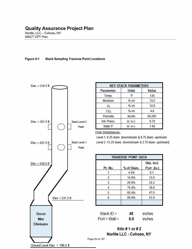
Quality Assurance Project PlanNorlite, LLC – Cohoes, NY MACT CPT Plan
Figure 4-1 Stack Sampling Traverse Point Locations
Page 63 of 107

Quality Assurance Project PlanNorlite, LLC – Cohoes, NY MACT CPT Plan
4.2.3 PCDDs / PCDFs
A Method 0023A sampling train will be used to sample for designated parameters. Specific sampling details for the Method 0023A sampling train are as follows:
Target sampling rate - 0.75 cfm
Sample run time - 3-hr
Minimum sample volume required [as per 40 CFR 63.1208(b)(1)(ii)] - 2.5 dscm (88.3 dscf)
Sample train rinse solvents: acetone, methylene chloride and toluene
No. of sampling points per stack traverse - 6
Total No. of sampling points - 12
Number of field reagent blank sets collected – 1
The sampling train consists of 5 glass impingers connected in series with leak-free ground glass and Teflon o- ring connections. The first impinger is left empty and the second and third impingers are filled with 100-mL of HPLC water; the fourth impinger is empty and the fifth impinger is loaded with ~ 400 g of silica gel. The sampling train uses an untared glass fiber filter, an XAD resin trap and condensing module and is operated as specified in the method. Details pertaining to the setup and recovery of the sampling train are presented in Attachment B to this QAPP.
4.2.4 Metals
EPA Method 29 will be utilized for the collection of MACT and other metals including:
MACT LVM metals – arsenic, beryllium, and chromium.
MACT SVM metals – cadmium and lead; and
Mercury.
Specific sampling details for the Method 29 sampling train are as follows:
Target sampling rate - 0.75 cfm
Sample run time - 2-hr
Estimated sample volume – 2.4 dscm (85.0 dscf)
No. of sampling points per stack traverse – 6
Total number of sampling points – 12
Number of field reagent blank sets collected – 1
Page 64 of 107

Quality Assurance Project PlanNorlite, LLC – Cohoes, NY MACT CPT Plan
4.2.5 PM and HCl / Cl2
Sampling for PM, HCl, and Cl2 will be performed in accordance with EPA Methods 5 and 26A. Specific sampling details for the Method 26A sampling train are as follows:
Target sampling rate - 0.75 cfm
Sample run time - 2-hr
Estimated sample volume – 2.4 dscm (85.0 dscf)
No. of sampling points per stack traverse – 6
Total number of sampling points – 12
Number of field reagent blank sets collected – 1
4.2.6 Continuous Emission Monitoring - CK
Measurement of O2 and CO2 for gas stream molecular weight determination and constituent oxygen correction will be determined in accordance with EPA Method 3A (continuous instrument analyzer method) during all test runs. These data will be obtained from the certified facility CEMS.
4.2.7 Continuous Emission Monitoring – Norlite
Plant-owned CEMS will be used during all test runs to monitor the concentrations of O2 and CO in the stack gas and to measure flue gas flow rate. Specifications for Norlite’s CEMS were provided earlier in Section 4.5 and Table 4-3 of the CPT Plan. Stack gas is continuously drawn through a filter and heated sample transport line. The gas is conditioned to remove water, and any condensate is removed. The resulting dry gas flows into each of the gas analyzers. The O2 results are used to correct the CO reading to 7% O2 using the following equation:
COCorr = COmeas x (13.9 / (20.9 – Y)) COcorr = CO concentration corrected to 7% oxygen
COmeas = CO concertation as measured directly in stack gas stream
Y = the oxygen content measured in the stack gas stream
From the O2 corrected readings, a one-minute average CO concentration is calculated every minute. At each successive minute, the 60 most recent one-minute average CO concentrations are used to calculate an hourly rolling average (HRA) CO concentration. The one-minute and HRA CO (O2 corrected) and O2 concentrations are automatically recorded by the process control / data acquisition system. If the HRA CO concentration exceeds 100 ppmv corrected to 7% O2, then an automatic waste feed cutoff (AWFCO) is initiated. As per the requirements of 63.1209(a)(3), one-minute average CO values that exceed the upper span limit for the analyzer (3,000 ppm) will be recorded as 10,000 ppm and used in the calculation of the HRA.
The system will be certified prior to conducting the CPT following the performance specification (PS) test procedures provided in PS 2 (“Specifications and Test Procedures for SO2 and NOx Continuous Emission Monitoring Systems in Stationary Sources”), PS 3 (“Specifications and Test Procedures for O2 and CO2
Continuous Emission Monitoring Systems in Stationary Sources”) and 4B (“Specifications and Test Procedures for Carbon Monoxide and Oxygen Continuous Monitoring Systems in Stationary Sources”) found in 40 CFR Part 60, Appendix B. In addition, the certification will follow the general guidelines outlined
Page 65 of 107

Quality Assurance Project PlanNorlite, LLC – Cohoes, NY MACT CPT Plan
in the Appendix to Subpart EEE (“Quality Assurance Procedures for Continuous Emissions Monitors Used for Hazardous Waste Combustors”).
Subsequent CEMS certification will take place in accordance with the normal schedule followed by the facility. This normal schedule includes daily calibrations, quarterly CGAs and annual RATA in accordance with the regulations.
Page 66 of 107

Quality Assurance Project PlanNorlite, LLC – Cohoes, NY MACT CPT Plan
5.0 Sample Custody
A variety of activities are performed prior to and during the field sampling program to ensure proper sample collection, documentation, and sample transport. These activities include equipment calibration, sample media preparation, cleaning of sample train glassware, preparation of computer-generated sample labels, and other miscellaneous tasks. Each of these activities are described or referenced in the following subsections. Other pre-sampling activities include such details as team meetings, equipment packing and shipment, equipment setup, and finalization of all details leading up to the coordinated initiation of the sampling program.
5.1 Field Sampling Operations
5.1.1 Glassware Preparation
Sample train glassware and sample containers require specialized pre-cleaning to avoid contamination of the sample from the collection container or devices. Cleaning/storage procedures for sample train glassware are summarized below. Note that all bottle caps are fitted with Teflon liners which are cleaned in the same manner as the bottles themselves. Sample containers used for all waste feed and stack gas samples are purchased pre-cleaned and sealed to specified EPA protocols (PC class).
EPA Method 0023A glassware and containers (PCDDs/PCDFs) - wash with soap and water, rinse
three times with deionized (DI) water, bake at 400°C for 2-hours, rinse three times with pesticide grade methylene chloride, rinse three times with pesticide grade toluene and air dry. Open ends will be sealed prior to shipment to the field with clean aluminum foil.
EPA Method 29 glassware and containers (metals) – wash with soap and water, rinse with hot tap water, and rinse three times with reagent water. The glassware is next soaked in a 10% nitric acid solution for a minimum of 4-hours, rinsed three times with reagent water, rinsed a final time with acetone and air dried. All glassware openings where contamination can occur will be covered with paraffin until the sampling train is assembled prior to sampling.
EPA Methods 5 and 26A glassware and components (PM and HCl/Cl2) – wash with soap and water, rinse three times with deionized (DI) water and air dry. Open ends will be sealed prior to shipment to the field with paraffin.
RM0030 - The glass resin tubes and condensers should be cleaned with a nonionic detergent in an ultrasonic bath, rinsed well with organic-free water, and dried at 110EC. Resin tubes of the I/O design should be assembled prior to storage as described in Paragraph 4.1. Resin tubes of the I/I design can be stored in glass culture tube containers with cotton cushioning and Teflon-lined screw caps. Condensers can be capped with appropriate end caps prior to use.
5.1.2 Sample Labels and Sampling Checklists
Preprinted sample identification labels are used to ensure that all required information is fully documented. When sample batches are shipped to the specified laboratory, a sample packing list (chain-of-custody form) such as that shown in Figure 5-1 accompanies the shipment. This form is based on established laboratory format and will be used to document sample transfer in the field and from sampling personnel to the laboratory. CK prepares sample labels prior to mobilizing to the field.
Page 67 of 107

Quality Assurance Project PlanNorlite, LLC – Cohoes, NY MACT CPT Plan
Figure 5-1 Sample Packing List and Sample Label
Sample Packing List Site of Program: Sample Date: Project Location:
Type of Program: Date Shipped: Analytical Lab:
Project #: Shipper: Lab P.O. #:
Program Office: Contact: FedEx Air Bill #:
Sample ID Sample Matrix Sample Description Analyses Instructions
Fie ld Note s / Com m e nts
Relinquished By: Date: Signature: Time:
Received By: Date: Signature: Time:
Analytical Labor ator y De s tination:
EXAMPLE SAMPLE LABEL
Sample Date:
Analytical Parameters:
Sampler:
Site of Program:
Project No.:
Sample Matrix:
Sample Description:
Sample ID Code: Special Instructions:
Page 68 of 107

Quality Assurance Project PlanNorlite, LLC – Cohoes, NY MACT CPT Plan
5.1.3 Preliminary Measurements
Preliminary tests will be conducted at the stack location to verify the presence or absence of cyclonic flow conditions and to determine flue gas moisture, temperature, and velocity. These measurements facilitate determination of nozzle size selection and sample train operation rates for the isokinetic sampling trains.
5.1.4 Field Documentation
The field team leader will maintain a field log of all daily activities including facility preparations, sample run times, problems encountered, any corrective actions taken, and other important events related to ash or POHC spiking or equipment operation. The field log will be included in an appendix of the final report.
All materials such as field and laboratory notebooks and logbooks, field and laboratory data records, correspondence, reports, sample tags, traceability records and instrument printouts will be clearly labeled with the project number and become a permanent part of the project file. Project samples will be disposed of in an appropriate manner 60 days after acceptance and approval of a final report. All project-related documentation at CK and the subcontractor laboratories will be kept on file for 2 years following submittal of the final report.
5.2 Field Laboratory Operations
5.2.1 Sample Media Preparation
All reagents will be purchased new with manufacturer purity certifications to minimize the probability of using contaminated solvents. This includes the use of the proper grade reagents/solvents as specified in the test method, selection of reagents from the same lot and the collection and analysis of the appropriate blanks. Bureau Veritas Laboratories will supply CK with sampling media procured and prepared in accordance with the appropriate test methods as described below:
XAD resin used in the Method 0023A sampling train is purchased new and packed in specially
designed sorbent traps by BV. All glass cleaning and sorbent packing procedures will follow the protocols specified in EPA Method 0023A.
Teflon filters used in the Method 26A sampling train will be supplied by BV with the method required technical specifications and efficiency ratings.
Quartz filters used in the Method 29 sampling train will be supplied by BV and pre-screened for metals content.
5.2.2 Field Laboratory Facility
Norlite will provide an office space/work area or mobile trailer to serve as a clean area for equipment staging, sample train setup and recovery, team meetings and to serve as the central area for coordinating testing activities and interacting with facility and Agency personnel. Special areas will be established in this trailer for setting up and recovering the isokinetic sampling train and/or for performing preliminary equipment checks. The use of special designated areas for each sampling train will help to eliminate sample train cross- contamination and ensure that the appropriate solvents and reagents are kept in their own specific area for use on the sampling train intended.
Page 69 of 107

Quality Assurance Project PlanNorlite, LLC – Cohoes, NY MACT CPT Plan
5.2.3 Sample Storage
Sample integrity will be maintained throughout all phases of the sampling and analysis program. Samples will be held within sight of the samplers or sample custodian or will be kept in sealed or secured containers at all times. Sealed coolers will be used to transport samples. Samples will be transported to BV via laboratory courier. Samples for Adirondack Laboratories will be hand delivered by Norlite personnel.
5.2.4 Sample Shipment
The CK field team leader will coordinate the packing and transport of all samples. Sample Chain-of-Custody forms, specifically designed for this program, will be generated prior to the field effort. These sheets will assist in assuring that all samples have been collected, accounted for, and shipped under sample traceability documentation to the appropriate laboratory.
5.2.5 Sample Preservation and Holding Times
All samples will be kept on ice in method-specific coolers until they are ready for shipment to the designated laboratory. As stated earlier, these samples will be transported in sealed coolers. Table 5-1 below provides additional requirements pertaining to sample preservation and recommended holding times.
Table 5-1 Sample Preservation and Holding Time Requirements
Stack Gas Samples (a)
Parameter
Matrix
Preservation
Holding Time
PCDDs/PCDFs (Method 0023A)
XAD Resin
Cool, 4°C
30 days (to extraction)
45 days (extraction to analysis)
Mercury
(Method 29)
Aqueous N/A 28 days
Solid/Filter N/A 28 days
Non-Mercury Metals (Method 29)
Aqueous N/A 6 months
Solid / Filter N/A 6 months
HCl /Cl2
(Method 26A)
Aqueous
N/A
30 days
RM 0030 Tenax Charcoal Cool, 4°C 30 days
(a) Holding times will be calculated from the day of sample collection.
Waste Feed Samples
Parameter Matrix Preservation Holding Time
Metals Aqueous Liquid Cool 6 months
Metals - Mercury Aqueous Liquid Cool 28 days
Page 70 of 107

Quality Assurance Project PlanNorlite, LLC – Cohoes, NY MACT CPT Plan
Total Chlorine Aqueous Liquid Cool 30 days
Page 71 of 107

Quality Assurance Project PlanNorlite, LLC – Cohoes, NY MACT CPT Plan
6.0 Field Equipment Calibration Procedures and Frequency
A very important aspect of pre-sampling preparations is the inspection and calibration of all equipment planned to be used for the field effort. Equipment is inspected for proper operation and durability prior to calibration. Calibration of equipment is conducted in accordance with the procedures outlined in the EPA document entitled "Quality Assurance Handbook for Air Pollution Measurement Systems; Volume III—Stationary Source Specific Methods" (EPA/600/R-94/038c, September 1994). Equipment calibration is performed in accordance with EPA guidelines and/or manufacturer’s recommendations. Documentation of all calibration records will be kept in the project file during the field program and will be available for inspection by test observers. Recommended practices from the QA Handbook for field equipment to be used during this program and specific calibration procedures performed by CK are listed below.
Sampling Nozzles [QA Handbook Section 3.4.2, pg. 19 - make three measurements of the nozzle ID
(to the nearest 0.001 in.) using different diameters with a micrometer. Difference between the high and low values should not exceed 0.004 in. Post-test check - inspect for damage.] Each glass nozzle is calibrated with a micrometer prior to testing and identified with a unique ID number. Any stainless-s t e e l nozzles used during the program are calibrated onsite prior to testing.
Pitot Tubes [QA Handbook Section 3.1.2, pp. 1-13 - measured for appropriate spacing and dimensions or calibrate in a wind tunnel. Rejection criteria given on the calibration sheet. Post-test check - inspect for damage.] Each S-type stainless steel Pitot tube used is designed to meet geometric configurations as defined in EPA Method 2.
Thermocouples [QA Handbook Section 3.4.2, pp. 15-18 - verify against a mercury-in-glass thermometer at two or more points including the anticipated measurement range. Acceptance limits - impinger ±2°F; DGM ±5.4°F; stack ±1.5 percent of stack temperature.] The Type K thermocouples in each meter control box, heated sample box, impinger umbilical connector, XAD resin trap, and sample probe are calibrated against ASTM mercury-in-glass thermometers at two or more points: an ice bath, ambient temperature and a boiling water bath.
Dry Gas Meters [QA Handbook Section 3.4.2, pp. 1-12 - calibrate against a wet test meter or calibrated orifice. Acceptance criteria - pretest Yi = Y ± 0.02; post test Y = ± 0.05 Yi.] Dry gas meters for all sampling trains are calibrated using critical orifices. The procedure entails four runs using four separate critical orifices running at an actual vacuum 1-2 in. greater than the theoretical critical vacuum. The minimum sample volume required per orifice is 5 ft3. Meter boxes are calibrated annually and then verified by use of the alternative Method 5 post-test calibration procedure. This procedure is based on the principles of the optional pretest orifice meter coefficient check outlined in Section 4.4.1 of Method 5. The average Y-value obtained by this method must be within 5% of the initial Y-value.
Field Balance The analytical balance used in the field to determine initial and final silica gel weights is calibrated against Class M weights provided by the Mettler Corporation (or equivalent).
Field Barometer [QA Handbook Section 3.4.2, pp. 18-19 - compare against a mercury-in-glass barometer or use Airport Station BP and correct for elevation. Acceptance criteria - ± 0.02 in. Hg; post-test check - same.] In the absence of pressure readings from an onsite laboratory or other weather station, BP readings will be obtained from the closest airport and corrected for elevation (-0.10 in. Hg per 100-ft of elevation increase as per Section 6.1.2 of EPA Reference Method 5).
Page 72 of 107

Quality Assurance Project PlanNorlite, LLC – Cohoes, NY MACT CPT Plan
6-2
CEMS Equipment and Instrumentation – Although not planned for this field program, should any CEMS equipment be brought to the site, it will be housed in a dedicated trailer that is transported to the test site and set up adjacent to the sampling location. All equipment (analyzers, calibration gases and ancillary equipment) is thoroughly checked prior to each job and the appropriated calibration standards are procured. Daily calibrations and other instrument bias checks are performed in accordance with the specific method followed.
All field equipment is calibrated annually or more often if problems occur. Copies of all calibration data for the equipment to be used on this test will be brought to the test site and a copy will be made available to the test observer, if requested. All calibration data are also subsequently included in the final report appendices.
Page 73 of 107

Quality Assurance Project PlanNorlite, LLC – Cohoes, NY MACT CPT Plan
7.0 Analytical Methods and Procedures
This section delineates the analytical protocols that will be followed to analyze samples during this test program. The methods cited will be followed as written unless specific modifications are made in the laboratory’s standard operating procedures (SOPs). Samples of kiln feed materials and stack gas will be collected and analyzed for the parameters previously discussed using the appropriate laboratory protocols detailed in this section and as outlined previously in Section 6.0 of the CPT Plan. All methods will be EPA methods, unless noted otherwise.
Page 74 of 107

Quality Assurance Project PlanNorlite, LLC – Cohoes, NY MACT CPT Plan
Table 7-1 below provides a detailed summary of the overall sampling and analysis program including the number of field, QA/QC and audit samples anticipated for the program. Appropriate accreditations and/or certifications for each analytical laboratory are provided in Appendix D of this document.
Table 7-1 Detailed Overview of Sampling and Analysis Program – per Kiln per Condition
Stream /
Sampling Method
Analytical
Parameters
Analytical Method
Lab (a)
Total Samples Analyzed
Field
Field Blanks
Audit
Lab QC
Total
Liquid Fe e ds [LLGF and Us e d Oil (if fed)] --
Grab /
Composite
Mercury EPA M 7471B &
ADIR 3 0 0 2 5
Other Metals (b) EPA M 3051A/6010C ADIR 3 0 0 2 5
Density Gravimetric (c) ADIR 3 0 0 1 4
Total Chlorine EPA M 5050
EPA M 9253
ADIR 3 0 0 2 5
Ash Content ASTM D 482-13 ADIR 3 0 0 1 4
Sediment ASTM D 1796-97 (d) ADIR 3 0 0 1 4
Heat Content ASTM D 240-17 ADIR 3 0 0 1 4
Shale --
Grab /
Composite
Mercury EPA M 7471B ADIR 3 0 0 2 5
Other Metals (b) EPA M 3051A/6010C ADIR 3 0 0 2 5 Total Chlorine EPA M 5050 / 9056A ADIR 3 0 0 2 5
Stack Gas --
EPA M 5
EPA M 26A
PM EPA M 5 BV 3 1 0 0 4
HCl and Cl2 EPA M 26A BV 3 1 1 2 7
EPA M 0023A PCDDs/PCDFs EPA M 0023A BV 3 1 0 2 6
EPA M 29 Mercury EPA M 29 BV 3 1 1 2 7
EPA M 29 Other Metals (b) EPA M 29 BV 3 1 1 2 7
EPA M 3A O2 & CO2 EPA M 3A (CEMS) NORL 3 0 0 0 3
EPA 0025A/18 VOC EPA 0025A/18 CK 3 0 0 0 3
RM 0030 VOC RM 0030 BV 3 1 0 1 5 Facility CEM O2 and CO Facility CEM QA Plan NORL 3 0 0 0 3
(a) Laboratories identified as follow s:
ADIR = Adirondack Environmental Services in Albany, NY
NORL = Norlite onsite laboratory.
BV = Bureau Veritas Laboratories
(b) Other metals: arsenic, beryllium, cadmium, chromium, and lead (MACT) (c) Density determination will be in accordance with Norlite's analytical SOP # 04-012. (d) Sediment determination will be in accordance with Norlite's analytical SOP # 04-049.
Page 75 of 107

Quality Assurance Project PlanNorlite, LLC – Cohoes, NY MACT CPT Plan
7.1 Analysis of Kiln Feed Materials
Analyses to determine the chemical and physical properties and metals content of the kiln feed materials will be performed using appropriate ASTM or EPA analytical methods as summarized in Table 7-2 below. Quality assurance requirements for these determinations are summarized in Tables 7-3 and 7-4.
Table 7-2 Sampling and Analytical Summary for LLGF and Shale
Analytical Parameter LLGF Shale
Total Chlorine EPA M 5050 (Prep) EPA M 9253 (Silver Nitrate Titration)
EPA M 5050 (Prep) EPA M 9056A (IC)
Mercury EPA M 7471B EPA M 7471B
Other Metals EPA M 3051A (Prep) EPA M 6010C
EPA M 3051A (Prep) EPA M 6010C
Sediment ASTM D 1796-97 (Norlite SOP # 04-049) Not Applicable
Ash Content ASTM D 482-13 Not Applicable
Density Gravimetric (Norlite SOP # 04-012) Not Applicable
Heat Content ASTM D 240-17 Not Applicable
Table 7-3 QA/QC Procedures for Total Chlorine in Kiln Feed Materials
Quality Parameter Method Determination Frequency Target Criteria
Calibration Initial analysis of blank plus 3 standards
Prior to sample analysis Instrument dependent. Linear correlation coefficient >=0.995
Continuing calibration standards
Before and after sample analysis; once per batch
90%-110% of expected value
Accuracy - calibration
Analysis of calibration check standard
After every calibration 90%-110% of expected value
Accuracy - spikes Spike sample at twice sample level
Once every 20 samples 80% to 120% of expected value
Accuracy – SRM Analysis of a standard reference material (SRM)
Once per test 90% to 110% of reference value
Precision Duplicate preparation and analysis of at least one run’s samples
Once per waste stream 10% RPD
Blank Method blank carried through all sample preparation and analysis steps
Once per batch Below detection limit
Page 76 of 107

Quality Assurance Project PlanNorlite, LLC – Cohoes, NY MACT CPT Plan
Table 7-4 QA/QC Procedures for Metals in Kiln Feed Materials
Quality Parameter
Method Determination
Frequency
Target Criteria
Calibration Initial analysis of standards at different concentration levels
At least once before sample analysis
Instrument-dependent. Linear correlation coefficient >=0.995
Continuing mid-range calibration standard
Before and after sample analysis
80% to 120% of expected value for GFAA and CVAA. 90% to 110% of expected value for ICAP
Interference check
Interference check sample Before ICAP analysis 80% to 120% of expected value
Accuracy – calibration
Analysis of calibration check standard
After every initial calibration
90% to 110% of expected value
Accuracy – spikes (pre- digestion)
Aliquot of one sample from a run spiked with analytes at 3 times the detection limit or twice the sample level prior to digestion (a)
One per sample matrix 70% to 130% recovery
Accuracy – SRM Analysis of NIST standard reference material (SRM)
Once per matrix 80% to 120% of stated reference value
Precision Duplicate preparation and analysis of one sample from each matrix
One per sample matrix Range < 35% if sample result above lowest standard
Blank Method blank carried through all sample preparation and analysis steps
Once per sample batch Below detection limit
GFAA = graphite furnace atomic absorption
CVAA = cold vapor atomic absorption
ICAP = inductively coupled argon plasma
(a) The initial spiking level will be approximately 3 times the detection limit. If spike recoveries are not acceptable due to matrix interference, the analysis will be repeated with spiking levels at twice the sample concentration.
Page 77 of 107

Quality Assurance Project PlanNorlite, LLC – Cohoes, NY MACT CPT Plan
7.2 Analysis of Stack Gas Samples
7.2.1 PCDDs / PCDFs in Stack Gas Samples
Stack flue gas samples collected using the Method 0023A sampling train will be analyzed for polychlorinated dibenzo-p-dioxins and polychlorinated dibenzofurans (PCDDs/PCDFs) by BV. Each sampling train will be prepared and split appropriately as specified in Method 0023A. Separate front half and back half analyses will be performed.
Method 0023A analyses (which include high resolution GC/MS as per EPA Method 0023) incorporate five isotopically labeled PCDD and PCDF field surrogates and nine labeled PCDD/PCDF internal standards. Table 7-5 summarizes the spiking quantities for all standards and surrogates for this program. Working level solutions are prepared from purchased certified NIST traceable individual stock solutions or mixes, when available for each type of standard listed in Table 7.5. Prespike (PS) or Surrogate Standard: Each individual compound is purchased as a concentrated solution at 50ug/ml and diluted accordingly to make a working level solution at 100pg/uL. 20uL of the working level solution is added per split to the media (XAD resin) prior to shipping out for sampling. Prespike (PS) or surrogate standards are measured relative to the internal standards and are a measure of the collection efficiency Native: Tetra to Hepta Dioxin mix at 25ug/mL, Tetra to Hepta Furan mix at 25ug/mL, OCDF at 50ug/mL and OCDD at 50ug/mL are combined to make a working level solution at 250pg/uL for the Tetra to Hepta dioxin and furans and 500pg/uL for the OCDF and OCDD. 5uL of the working level standard is added prior to extracting the OPR and OPR Duplicate. The OPR and OPR duplicate are used to demonstrate the precision and accuracy associated with laboratory procedures, but, not with sample collection. Internal (Labeled Standard): Individual stock 13C labeled congeners at 50ug/mL are combined to make a working level Internal standard at 100pg/uL for each of the Tetra to Hepta labeled congeners and 200pg/uL for labeled OCDD. 13C-12 OCDF is not added as per EPA Method 23. OCDF results are recovery corrected using 13C-12 OCDD. 20uL of the working level standard is added to each of the QC and client samples prior to extraction. These are used to quantify the PCDD’s and PCDF’s present in the sample, as well as to determine the overall method extraction efficiency.
Page 78 of 107

Quality Assurance Project PlanNorlite, LLC – Cohoes, NY MACT CPT Plan
Cleanup (Alternate Standard): Stock solution is purchased at 50ug/mL and is diluted to prepare a working standard at 100pg/uL. 20uL of the working level alternate standard is added to the concentrated extract following extraction just prior to beginning the chromatographic cleanup steps. This serves to indicate if any losses may have occurred during the cleanup steps. Recovery Standard (Injection Standard): Individual 13C labeled stock solutions @ 50ug/mL are combined to make an Injection / Recovery standard at 100pg/uL. 20uL of this recovery (injection) standard is added to each cleaned up extract just prior to injecting for analysis on the HRGC/ HRMS. This serves to correct the internal standard recoveries for instrument response and any injection variability encountered. QA/QC requirements for these analyses are summarized in Table 7-6.
Page 79 of 107

Quality Assurance Project PlanNorlite, LLC – Cohoes, NY MACT CPT Plan
Table 7-5 Standard Spiking Requirements for Method 0023A
Type of Standard
Time of Addition
Amount Added (pg/SPLIT) Analytes
Prespike (PS) Prior to sampling 37Cl4-2,3,7,8-TCDD 200013C-2,3,4,78-PeCDF 200013C-1,2,3,4,7,8-HxCDD 2000
13C-1,2,3,4,7,8-HxCDF 200013C1,2,3,4,7,8,9-HpCDF 2000
Native Prior to extraction (OPR only)
2,3,7,8-TCDD 1250 2,3,7,8-TCDF 12501,2,3,7,8-PeCDD 12502,3,4,7,8-PeCDF 12501,2,3,7,8-PeCDF 12501,2,3,4,7,8-HxCDD 12501,2,3,6,7,8-HxCDD 12501,2,3,7,8,9-HxCDD 12501,2,3,4,7,8-HxCDF 12501,2,3,6,7,8-HxCDF 12501,2,3,7,8,9-HxCDF 12502,3,4,6,7,8-HxCDF 12501,2,3,4,6,7,8-HpCDD 12501,2,3,4,6,7,8-HpCDF 12501,2,3,4,7,8,9-HpCDF 1250OCDD 2500OCDF 2500
Internal (IS) Prior to extraction 13C-2,3,7,8-TCDD 200013C-2,3,7,8-TCDF 200013C-1,2,3,7,8-PeCDD 2000 13C-1,2,3,7,8-PeCDF 200013C-1,2,3,6,7,8-HxCDD 200013C-1,2,3,6,7,8-HxCDF 2000 13C-1,2,3,4,6,7,8-HpCDD 2000
13C-1,2,3,4,6,7,8-HpCDF 200013C-OCDF Not added 13C-OCDD 4000
Cleanup (AS) Before cleanup 13C-1,2,3,7,8,9-HxCDF 2000
Recovery Prior to analysis 13C-1,2,3,4-TCDD 2,00013C-1,2,3,4-TCDF Not added13C-1,2,3,7,8,9-HxCDD 2,000
Page 80 of 107

Quality Assurance Project PlanNorlite, LLC – Cohoes, NY MACT CPT Plan
Table 7-6 QA Objectives for PCDD/PCDF Analysis of Stack Gas Samples
Quality Parameter Method Determination Frequency Target Criteria
Calibration Five-level calibration curve; continuing calibration standard
At least once, continuing calibration check at beginning of each 12-hr shift
Initial:
<=25% RSD for unlabelled standards
<=30% RSD OCDD
<=25% RSD for TCDD and
HxCDD internal standards
<=30% Remaining Internal
Standards
Reference: Table 3.4-5 Method 23 (40 CFR Ch.1 (7-1-91 Edition)
S/N ratio >=10
Isotope ratios within control
limits
Reference: Table 3.4-3 in EPA Method 23 (40 CFR Ch.1 (7-1-91 Edition) Continuing:
<=25% of ICAL for 16 unlabeled stds<=30% of ICAL for unlabeled OCDD, OCDF <=25% of ICAL for Tcdd and HxCDD internal standards
<=30% of ICAL for remaining
Reference: Table 3.4-5 Method 23 (40 CFR Ch.1 (7-1-91 Edition)
Internal standards S/N ratio >=10;
Isotope ratios within control limits
Reference: Table 3.4-3 in EPA Method 23 (40 CFR Ch.1 (7-1-91 Edition)
Accuracy-calibration Analysis of calibration check
After every initial calibration
80% - 120% of theoretical value
Accuracy- surrogates
Spiked into samples prior to sampling
Every sample 70% - 130% recovery
Accuracy-internal standards
Spiked into samples prior to extraction and analysis
Every sample 40%-130% recovery for tetra – octa homologs
Accuracy – audit samples
Prepared and analyzed along with program samples
Presented by the regulatory agency
Determined by regulatory agency
Page 81 of 107

Quality Assurance Project PlanNorlite, LLC – Cohoes, NY MACT CPT Plan
Table 7-6 QA Objectives for PCDD/PCDF Analysis of Stack Gas Samples (Continued)
Blanks Method blank for each component
Field blank
One per batch of samples
Once per test
< RDL or <5% of field concentration
Evaluated on a case-by-case basis
Mass Spectrometer Performance
Section 9.3.2 of Method 8290
At the beginning and end of each 12-hr period
Static resolving power of 10,000 (10% valley definition)
GC Performance Retention Time and GC Column Performance
At the beginning of each 12-hr period
Compliance with Section 9.3.1 of Method 8290- Same for M23
Qualitative Identification
Identification Criteria Every sample Compliance with Section 11.8.4 of Method 8290. Same for M23
S/N = Signal to Noise Ratio
RSD = Relative Standard Deviation
7.2.2 Metals in Stack Gas Samples
Each sampling train will be prepared and recovered by CK. Samples will be analyzed by BV in accordance with EPA Reference Method 29. Target parameters will be reported separately in each sample train fraction (as outlined below) and blank- corrected in accordance with method-specific procedures.
From each sampling train, seven individual samples are generated for analysis. The first two samples, labeled Fractions 1A and 1B consist of the digested sample from the front half of the train, consisting of the particulate filter and the front-half nitric acid probe rinse. Fraction 1A is for inductively coupled argon plasma emission spectroscopy (ICAP) analysis and Fraction 1B is for mercury analysis. Fractions 2A and 2B consist of digestates from the moisture knock out and HNO3/H2O2 impingers 1, 2, and 3. Fraction 2A is for ICAP analysis and Fraction 2B is for mercury analysis. Fractions 3A, 3B, and 3C consist of the impinger contents and rinses from the empty and permanganate impingers 4, 5, and 6. These fractions will be analyzed for mercury.
Mercury analysis will be performed using EPA Method 7470A (SW-846, 3rd Edition). All quality control procedures, including the interference check standard, will be followed as described in the method.
Instrument calibration will be performed daily in accordance with the procedures described in Method 6020B and the manufacturer's instructions. The calibration is verified daily by analysis of an instrument check standard prepared from an EPA quality control concentrate or another independent standard.
QA/QC requirements for the analysis of metals in stack gas samples are summarized in Table 7-7.
Page 82 of 107

Quality Assurance Project PlanNorlite, LLC – Cohoes, NY MACT CPT Plan
Table 7-7 QA Requirements for Metals in Stack Gas by ICP-MS and CVAAS
7.2.3 Hydrogen Chloride and Chlorine in Stack Gas Samples
Impinger samples from the Method 26A sampling train will be analyzed by Bureau Veritas Laboratories (BV) by ion chromatography in accordance with EPA Method 26A.
The sodium hydroxide impinger samples are treated with sodium thiosulfate in the laboratory, the pH of the solution is adjusted to >9 by adding NaOH (10N) drop wise. The samples are treated with sodium thiosulfate by adding 20 μL sodium thiosulfate (1.0N). If the final dilution required exceeds 500, the sample is re-prepared by adding 20 μL sodium thiosulfate (1.0N) for each 500-fold dilution. QA/QC procedures for these analyses are presented in Table 7-8.
20%
Page 83 of 107

Quality Assurance Project PlanNorlite, LLC – Cohoes, NY MACT CPT Plan
Table 7-8 QA Requirements for Chlorides in Stack Gas
7.2.4 Particulate Matter in Stack Gas Samples
Gravimetric analyses will be performed by BV on samples collected from the Method 5/26A PM/HCl/Cl2
train. Weights will be obtained on the front-half acetone rinse and particulate filter using a calibrated analytical balance. Balance accuracy is checked by using Class "S" standard weights before and after tare weighing and sample determinations. Sample fractions are dried to constant weight, defined as two successive weighings at a 6-hr interval showing a weight change of less than 0.5 mg.
7.2.5 VOCs in Stack Gas Samples
Volatile Organic Constituents will be performed using two methods. EPA 0025A/18 is an instrumentation method that will be performed on site by CK environmental. RM 0030 will be performed by BV on samples collected during the test run. This method employs a 20-liter sample of effluent gas containing volatile POHCs which is withdrawn from a gaseous effluent source at a flow rate of 1 L/min, using a glass-lined probe and a volatile organic sampling train (VOST). The gas stream is cooled to 20EC by passage through a water-cooled condenser and volatile POHCs are collected on a pair of sorbent resin traps. Liquid condensate is collected in an impinger placed between the two resin traps. A total of six pairs of sorbent traps may be used to collect volatile POHCs from the effluent gas stream.
Page 84 of 107

Quality Assurance Project PlanNorlite, LLC – Cohoes, NY MACT CPT Plan
8.0 Quality Control Procedures
Quality control checks will be performed to ensure the collection of representative samples and the generation of valid analytical results for these samples. These checks will be performed by project participants throughout the program under the direction of the Project Manager and the QA Officer.
8.1 Field Sampling QC Procedures
QC checks for the process data collection and sampling aspects of this program will include, but not be limited to, the following:
1. Use of standardized data sheets, checklists and field notebooks to ensure completeness, traceability, and
comparability of the process information and samples collected.
2. Field checking of standardized forms by the Field Team Leader and a second person to ensure accuracy and completeness.
3. Strict adherence to the sample traceability procedures.
4. Submission of field biased blanks.
5. Leak checks of sample trains before and after sample collection and during the test, when appropriate.
8.1.1 Equipment Inspection, Maintenance and Calibration
CK maintains a dedicated facility for storage, maintenance, repair, and calibration of all field equipment. Prior to each job, project participants fully inspect and prepare all equipment that will be used.
Calibration of the field sampling equipment is performed in accordance with procedures recommended by the manufacturer and as described earlier in Section 6.0. Copies of the calibration sheets will be available onsite during the field sampling program for inspection, will be kept in the project file and will be incorporated as an appendix in the final report. Calibrations will be performed as described in the EPA publication "Quality Assurance Handbook for Air Pollution Measurement Systems, Volume III, Stationary Source Specific Methods;" Section 4.2.1 presents acceptance limits.
8.1.2 Sampling Equipment QC Checks and Frequency
Leak checks of the sample trains will be conducted in accordance with the protocol called out for each method. Leak checks will be conducted prior to and at the end of sample collection and during the test run, if the sampling train is disassembled for any reason or if the port change requires extensive movement of the train.
Field blanks of reagents and collection media (deionized water, filters, impinger solutions, sorbent material, etc.) will be placed in appropriately cleaned and sized sample containers in the field and handled in the same way as actual field samples, to provide a QC check on sample handling.
Page 85 of 107

Quality Assurance Project PlanNorlite, LLC – Cohoes, NY MACT CPT Plan
For this program, sample collection QC checks and frequency for samples to be analyzed in the laboratory are listed below:
One set of reagent/media blanks from the Method 0023A (PCDDs / PCDFs) sampling train
One set of reagent/media blanks from the Method 29 (metals) sampling train
One set of reagent/media blanks from the Method 26A (PM, HCl / Cl 2) sampling train
8.2 Analytical QC Procedures
The Quality Control program for laboratory analysis makes use of several different types of QC samples to document the validity of the generated data. The following types of QC samples will be used during the program.
8.2.1 Quality Control Samples and Blanks
Method Blanks
Method blanks contain all the reagents used in the preparation and analysis of samples and are processed through the entire analytical scheme to assess spurious contamination arising from reagents, glassware, and other materials used in the analysis.
Calibration Check Samples
One of the working calibration standards which is periodically used to check that the original calibration is still valid.
Laboratory Control Samples (LCS) or Blank Spikes
These samples are generated from spikes prepared independently from the calibration concentrates. The LCS are used to establish that an instrument or procedure is in control. An LCS is normally carried through the entire sample preparation and analysis procedure also.
Surrogate Spikes
Samples requiring analysis by GC/MS are routinely surrogate spiked with a series of deuterated analogues of the components of interest. It is anticipated that these compounds would assess the behavior of actual components in individual program samples during the entire preparative and analysis scheme.
The percent recovery for each surrogate will be calculated in accordance with method-specific procedures. Any values which fall outside the target QC limits described in the applicable analytical method will be flagged. Some of these recovery values may be outside the QC limit owing to matrix interferences. The following guidelines will be used:
1. All recovery data are evaluated to determine if the QC limits are appropriate and if a problem may exist
even though the limits are being achieved (e.g., one compound that is consistently barely within the lower limit).
Page 86 of 107

Quality Assurance Project PlanNorlite, LLC – Cohoes, NY MACT CPT Plan
2. Any recovery data which are outside the established limits are investigated. This evaluation will include an independent check of the calculation.
3. Corrective action will be performed if any of the following are observed:
All recovery values in any one analysis are outside the established limits, where one analysis is
one sample analyzed by one method,
Over 10 percent of the values for a given sample delivery group are outside limits, or
One compound is outside the limits in over 10 percent of the samples.
An analysis batch is defined as a group of ten or fewer samples carried through the entire preparation and analysis procedure in one batch.
Reagents used in the laboratory are normally of analytical reagent grade or higher purity; each lot of acid or solvent used is checked for acceptability prior to laboratory use. All reagents are labeled with the date received and date opened. The quality of the laboratory deionized water is routinely checked. All glassware used in the sampling and analysis procedures will be pre-cleaned according to the method requirements. Standard laboratory practices for laboratory cleanliness, personnel training and other general procedures are used. The results of these quality control procedures will be included in the final report.
Page 87 of 107

Quality Assurance Project PlanNorlite, LLC – Cohoes, NY MACT CPT Plan
9.0 Performance and System Audits
The sampling, analysis, and data handling segments of a project are checked in performance audits. A different operator/analyst prepares and conducts these audit operations to ensure the independence of the quantitative results.
EPA Quality Control concentrates or other standards will be used to assess the analytical work. Results will be reviewed by the subcontractor laboratory and QC personnel. CK will obtain commercially available audit samples from accredited audit sample provider and are evaluated during the performance test program. Audit samples as identified in Section 2.3 and Table 7.1 will be analyzed along with program samples, by the appropriate lab and at the same time as all other samples. Per the audit program, the results of these audits will be reported to the NYSDEC.
If the regulatory agency advises facility program manager that audit results fall outside of acceptable ranges, the analytical data will be further reviewed for error in conjunction with the agency. If a simple, correctable error is found (e.g., an arithmetic error), correction will be made, and results resubmitted. If no error is found, an investigation into other causes of the failure (e.g., lack of sample integrity) will be conducted and results evaluated in terms of the impact on sample data integrity.
Page 88 of 107

Quality Assurance Project PlanNorlite, LLC – Cohoes, NY MACT CPT Plan
10.0 Preventive Maintenance
This section provides pertinent information for field sampling equipment as well as a listing of all critical facility equipment necessary to maintain permitted operating conditions and to demonstrate continuing compliance. Information is provided for preventive maintenance and schedules and spare parts for key equipment and instrumentation.
10.1 Field Sampling Equipment
CK follows an orderly program of positive actions to prevent the failure of equipment or instruments during use. This preventive maintenance and careful calibration help to ensure accurate measurements and minimal field delays.
All equipment that is scheduled for field use is calibrated as outlined previously in Section 6.0. Prior to each field use for a specific project, the equipment is cleaned and checked to ensure it is in good working order. An adequate supply of spare parts and sample train glassware is brought to each site to minimize downtime and field sampling delays. Any equipment that does experience problems is appropriately tagged in the field to ensure that it is repaired upon return to the office.
10.2 Facility Equipment and Instrumentation
Norlite performs scheduled and preventative maintenance programs on the process equipment including mechanical, electrical, structural and instrument systems. These programs are designed with predictive maintenance goals to minimize and/or eliminate unscheduled shutdowns. Norlite operators perform daily inspections of equipment as well as perform scheduled preventative maintenance services such as cleaning, oiling, and greasing of components.
Page 89 of 107

Quality Assurance Project PlanNorlite, LLC – Cohoes, NY MACT CPT Plan
11.0 Procedures Used to Assess Data Precision and Accuracy
The QC activities implemented in this program will provide a basis for assessing the accuracy and precision of the analytical measurements. Section 8.0 of this QAPP discusses the various QC activities that will generate the accuracy and precision data for each sample type. A generalized form of the equations that will be used to calculate accuracy, precision and completeness follows.
11.1 Accuracy
Accuracy (calculated as percent recovery) will be determined using the following equation:
%Recovery = (X – S) x 100
Twhere:
X = experimentally determined concentration of the spiked sample
T = true concentration of the spike
S = sample concentration before spiking
11.2 Precision
Precision (calculated as percent relative difference) will be determined using the following equation:
Relative Percent Difference (RPD) = ((D1 – D2) / ((D2 + D1)/2)) X 100
where:
D1 and D2 = results of duplicate measurements or standard deviation relative to the average value expressed as relative standard deviation:
Relative standard deviation will be expressed as follows: RSD = s * 100
x
where: RSD = Relative standard deviation s = Standard deviation x = Mean of the data.
Page 90 of 107

Quality Assurance Project PlanNorlite, LLC – Cohoes, NY MACT CPT Plan
7-2
11.3 Completeness
Data completeness is a measure of the extent to which the database resulting from a measurement effort fulfills objectives for data required. For this program, completeness will be defined as the percentage of valid data for the total valid tests. Completeness is assessed using the following equation:
Completeness (%) = (Dr / Dc) * 100
where:
Dr = number of samples for which valid results are reported
Dc = number of valid samples that are collected and reach the laboratory for analysis
The completeness objective will help to evaluate the accuracy and precision of the analytical measurements.
Page 91 of 107

Quality Assurance Project PlanNorlite, LLC – Cohoes, NY MACT CPT Plan
.
12
12.0 Corrective Actions
The acceptance limits for the sampling and analyses to be conducted in this program will be those stated in the method or defined by the project manager. The corrective actions are likely to be immediate in nature and most often will be implemented by the analyst or Project Manager; the corrective action will usually involve recalculation, reanalysis, or repeating a sample run. Ongoing corrective action policy is described here.
12.1 Immediate Corrective Action
Specific QC procedures and checklists are designed to help analysts detect the need for corrective action. Often the person's experience will be more valuable in alerting the operator to suspicious data or malfunctioning equipment.
If a corrective action can be taken at this point, as part of normal operating procedures, the collection of poor-q u a l i t y data can be avoided. Instrument and equipment malfunctions are amenable to this type of action and QC procedures include troubleshooting guides and corrective action suggestions. The actions taken should be noted in field or laboratory notebooks, but no other formal documentation is required, unless further corrective action is necessary. These on-the-spot corrective actions are an everyday part of the QA/QC system.
Corrective action during the field sampling portion of a program is most often a result of equipment failure or an operator oversight and may require repeating a run. When equipment is discovered to be defective (i.e., pre- and post-sampling leak check) it is repaired or replaced, and a correction factor is established as per the EPA method. If a correction factor is unacceptable the run is repeated. Operator oversight is best avoided by having field crew members audit each other’s work before and after a test. Every effort is made by the field team leader to ensure that all QC procedures are followed. Economically, it is preferred to repeat a run during a particular field trip rather than return at a later date.
Corrective action for analytical work would include re-calibration of instruments, reanalysis of known QC samples and, if necessary, of actual field samples.
If the problem is not solved in this way, more formalized long-term corrective action may be necessary.
12.2 Long-Term Corrective Action
The need for this action may be identified by standard QC procedures, control charts, performance or system audits. Any quality problem which cannot be solved by immediate corrective action falls into the long-term category. The condition is reported to a person responsible for correcting it who is part of the closed-loop action and follow-up plan.
The essential steps in the closed-loop corrective action system are:
Identify and define the problem.
Assign responsibility for investigating the problem.
Investigate and determine the cause of the problem.
Page 92 of 107

Quality Assurance Project PlanNorlite, LLC – Cohoes, NY MACT CPT Plan
.
12
Determine a corrective action to eliminate the problem.
Assign and accept responsibility for implementing the corrective action.
Establish effectiveness of the corrective action and implement it.
Verify that the corrective action has eliminated the problem.
Documentation of the problem is important to the system. A Corrective Action Request Form is filled out by the person finding the quality problem. This form identifies the problem, possible causes and the person responsible for action on the problem. The responsible person may be an analyst, field team leader, department QC coordinator or the QA Director. If no person is identified as responsible for action, the QA Director investigates the situation and determines who is responsible in each case.
The Corrective Action Request Form includes a description of the corrective action planned and the date it was taken, and space for follow-up. The QA Director checks to be sure that initial action has been taken and appears effective and, at an appropriate later date, checks again to see if the problem has been fully solved. The QA Director receives a copy of all Corrective Action Forms and then enters them in the Corrective Action Log. This permanent record aids the QA Director in follow-up and makes any quality problems visible to management; the log may also prove valuable in listing a similar problem and its solution.
Page 93 of 107

Quality Assurance Project PlanNorlite, LLC – Cohoes, NY MACT CPT Plan
7-1
13.1 Data Reduction, Validation and Data Reporting
Specific QC measures will be used to ensure the generation of reliable data from sampling and analysis activities. Proper collection and organization of accurate information followed by clear and concise reporting of the data is a primary goal in all such projects.
13.1 Field Data Reduction
Attachment A presents the standardized forms that will be used to record field sampling data. The Field Team Leader and the QAO will review the data collected from each train in its entirety in the field. Errors or discrepancies will be noted and dealt with accordingly. Both the Field Team Leader and the QAO have the authority to institute corrective actions in the field. Field data reduction (checking of valid isokinetic sampling rate and other sampling parameters) is done with a laptop computer using standardized Excel spreadsheets. Attachment B provides both setup and recovery schematics and a description of solutions and reagents to be used in each impinger train required for the overall program. All sample recovery sheets will be checked for completeness.
13.2 Laboratory Data Reduction
Analytical results will be reduced to appropriate units by the laboratory using the equations given in the applicable analytical method. Unless otherwise specified, results from the analysis of liquid waste feed samples for specific target constituents will be reported in units of mg/kg or % wt. Other parameters will be reported in standard units such as g/cc, Btu/lb, etc.
The laboratory typically reports results from the analysis of stack flue gas samples as total mass detected for the sample submitted. For those sample fractions where liquid impinger condensate is analyzed, the laboratory will measure the total liquid volume submitted and multiply by the measured concentrations of target analytes in these samples. The laboratories will report data as follows:
Particulate matter – total mg collected in each sample train fraction (front-half rinse and filter)
Metals – total µg collected in each sample train fraction
PCDDs/PCDFs - total pg collected in each of the front-half and back-half sample train fractions
HCl /Cl2 – total µg collected in each sample train fraction as either HCl or Cl2
Each LSC will be responsible for reviewing all results and calculations and verifying the completeness of the data set. The laboratory reports submitted by each laboratory will include the following deliverables:
Transmittal letter listing all samples and analyses and a case narrative identifying any difficulties
associated with the analyses and any anomalous QA/QC results
Copies of Chain of Custody Forms
Page 94 of 107

Quality Assurance Project PlanNorlite, LLC – Cohoes, NY MACT CPT Plan
Sample Report forms with sample field and laboratory identifier, dates of sample preparation and analysis, analytical results, and detection limits
Method Blank results
MS and MSD results (as applicable)
Replicate sample analyses (as applicable)
Laboratory Control Sample results
Reports for organics in stack samples will include the following additional information:
Surrogate recoveries
Summary of initial calibrations
Continuing calibration summaries
Instrument tunes
Data Validation An electronic copy of the raw data, calculations spreadsheets, and analysis is to be submitted with the final report.
13.3 Data Validation
Data validation is the process of reviewing data and accepting, qualifying, or rejecting it based on method-specific criteria. The independent project QAO will use validation methods and criteria appropriate to the type of data and the purpose of the measurement. Records of all data will be maintained, even that judged to be an outlying or spurious value.
Field sampling data will be validated by the Field Team Leader based on a judgment of the representativeness of the sample, maintenance and cleanliness of sampling equipment and the adherence to an approved, written sample collection procedure.
Analytical data will be validated by the subcontractor laboratory QC or supervisory personnel using criteria outlined in their laboratory-specific QA Plan and/or written SOPs. Results from field and laboratory method blanks, replicate samples and internal QC samples will be used to further validate analytical results. Analytical results on field blanks and replicate field samples are valuable for validation of sample collection also. QC personnel will review all subcontractor laboratory raw analytical data to verify calculated results presented.
The following criteria will be used to evaluate the field sampling data:
Use of approved test procedures
Proper operation of the process being tested
Use of properly operating and calibrated equipment
Leak checks conducted before and after test runs
Use of reagents that have conformed to QC specified criteria, and
Page 95 of 107

Quality Assurance Project PlanNorlite, LLC – Cohoes, NY MACT CPT Plan
Use of Protocol 1 CEMS calibration gases
Proper chain-of-custody maintained
All sample trains --check to ensure proper sample gas volume collected
The criteria used to evaluate the analytical data are as previously defined in Section 3.0 (data quality objectives) and the method-specific QA summary tables listed in Section 7.0.
13.4 Data Reporting
13.4.1 Preliminary Data Reporting in the Field
At the end of each day of testing, several types of data will be made available to all project participants and test observers. Recovery of each isokinetic sampling train will include spreadsheet calculations to determine proper isokinetic sampling rate, stack gas moisture content, temperature and flowrate and sample volume. These data will be reviewed for acceptability and made available to facility personnel and Agency staff.
13.4.2 Preliminary Reporting of Results
In the weeks following test conclusion, all field data will be reviewed, and spreadsheet data entry will be checked for accuracy and completeness. As laboratory data become available, emission calculations will be performed, and results will be provided to Norlite and Agency personnel. Most importantly, the results of any failed tests will be provided as soon as the data are thoroughly checked for accuracy and associated QC data are determined to be acceptable.
13.4.3 Final Data Report
The final report for this project will be a comprehensive data compilation that properly and logically documents and certifies all required test results. The report will include all the required elements of a MACT NOC as outlined in Section 7 of the CPT Plan. CK plans to follow the guidance provided by EPA for a combined NOC and CPT report. As such, the report would be structured in a similar manner with sections delineated as follows:
Summary of Test Results
Introduction and Process Description
Process Operating Conditions
Feed Stream Sampling and Analysis
Performance Test Results
Quality Assurance / Quality Control Documentation
Continuing Compliance Methods
Report appendices will also provide detailed supporting documentation as delineated in the above referenced LDEQ guidance. Appendices for the project report would include:
Process Operating Data
Page 96 of 107

Quality Assurance Project PlanNorlite, LLC – Cohoes, NY MACT CPT Plan
Field Sampling Documentation
Sample Calculations
Analytical Data Reports
CMS / CEMS performance Evaluation Test Results An electronic copy of the raw data, calculations spreadsheets, and analysis is to be submitted with the final report.
13.4.4 Management of Non-Detects
There are several different scenarios regarding the handling of analytical data reported as ND in this program. First, for the purposes of determining compliance with feed rate limits that are calculated from analytical data, the full ND value (reporting limit) will be used.
In general, the emission tables to be generated for the final report will perform all calculations using either a real value or the detection limit (i.e. reporting limit) for those parameters reported as ND. Using the full detection limit in an emission calculation provides a worst-case assessment. When calculating dioxins emission rates, values reported as the detection limit will be handled as zero [63.1208(b)(1)(i)(B)(3)(iii)].
13.4.5 Oxygen Correction
In accordance with 63.1206(c)(2)(iii), the facility is required to identify a projected oxygen correction factor based on normal operations to be used during periods of startup and shutdown. Norlite does not presently envision the need to project any alternative correction factor. It should also be noted that all concentration- based emission results will be corrected to 7% oxygen in accordance with the MACT regulations.
13.4.6 Sampling Times and Calculation of Results
Stack gas concentrations for each applicable parameter will be calculated from laboratory results and field sampling data. The total weight of the analyte detected will be divided by the volume of gas sampled to provide emission concentrations. As stated above, all emission concentrations are further corrected to 7% oxygen for comparison to published standards.
13.4.7 Blank Correction
Except for PM samples no other samples collected on this program are allowed to be blank-corrected. PM acetone blank correction will be employed as need as specified in the method.
13.4.8 Rounding and Significant Figures
For purposes of final data reporting, the procedures outlined under 40 CFR 63.1221(d) with respect to rounding of emission results and use of significant figures are proposed. This regulation notes that for all emission parameters except DRE, intermediate calculations must be performed using at least three significant figures, but that the resultant emission levels may be rounded to two significant figures to document compliance.
Page 97 of 107

Quality Assurance Project PlanNorlite, LLC – Cohoes, NY MACT CPT Plan
13.4.9 Evaluating Compliance To determine compliance with applicable emission standards, the three-run arithmetic average for each target pollutant will be compared to the emission standard for all parameters except DRE. Each DRE run must satisfy limit to demonstrate compliance.
Page 98 of 107

Quality Assurance Project PlanNorlite, LLC – Cohoes, NY MACT CPT Plan
14.0 Quality Assurance Reports
14.1 Internal Reports
The Laboratory Services Coordinator will prepare a written report on QC activities associated with this project for the Quality Assurance Director. This report will detail the results of quality control procedures, problems encountered and any corrective action, which may have been required.
All Corrective Action Forms are submitted to the QA Officer for initial approval of the corrective action planned and a copy is provided to the Program Manager. All system audit reports are provided to the Program Manager and the Quality Assurance Officer.
14.2 Reports to Client
The final report will include a section summarizing QA/QC activities during the program. The Project Manager, Laboratory Services Coordinators and the QA Officer will participate in preparing this section. This section will provide summary QA/QC results for method blanks, surrogate spikes, and laboratory control spike recoveries. This section will evaluate overall data quality in terms of accuracy, precision, and completeness. Any discrepancies or difficulties noted in program work, protocol deviations or documentation gaps will be identified and discussed.
14.3 Regulatory Agency Notifications
NYSDEC will be notified for the purpose of their concurrence if there are any changes to the CPT plan or test methods. The agency will also be notified if any errors or discrepancies are discovered in the field data sheets upon review after returning from the field. Norlite will also notify NYSDEC at least 60 calendar days before the test is scheduled to begin.
Page 99 of 107

Quality Assurance Project PlanNorlite, LLC – Cohoes, NY MACT CPT Plan
ATTACHMENT A
Example Field Datasheets
Page 100 of 107
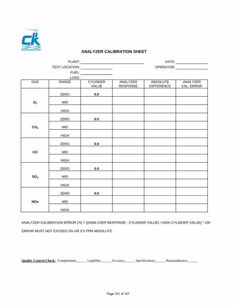
ANALYZER CALIBRATION SHEET
PLANT: DATE:
TEST LOCATION: OPERATOR:
FUEL:
LOAD:GAS RANGE CYLINDER ANALYZER ABSOLUTE ANALYZER
VALUE RESPONSE DIFFERENCE CAL. ERROR
ZERO 0.0
O2 MID
HIGH
ZERO 0.0
CO2 MID
HIGH
ZERO 0.0
CO MID
HIGH
ZERO 0.0
SO2 MID
HIGH
ZERO 0.0
NOx MID
HIGH
ANALYZER CALIBRATION ERROR (%) = [(ANALYZER RESPONSE - CYLINDER VALUE) / HIGH CYLINDER VALUE] * 100
ERROR MUST NOT EXCEED 2% OR 0.5 PPM ABSOLUTE
Quality Control Check: Completeness______ Legibility______ Accuracy______ Specifications______ Reasonableness______
Page 101 of 107

SYSTEM CALIBRATION SHEET
PLANT: DATE:
TEST LOCATION: OPERATOR:
FUEL: SYSTEM RESPONSE TIME:
LOAD:
O2 CO2 CO SO2 NOxRANGE: RANGE: RANGE: RANGE: RANGE:ZERO SPAN ZERO SPAN ZERO SPAN ZERO SPAN ZERO SPAN
ANALYZERCAL RESPONSEINITIAL SYSTEMCAL RESPONSE
RUN:______ SYSTEM BIAS
START FINAL SYSTEMTIME:______ CAL RESPONSE
SYSTEM BIASENDTIME:______ SYSTEM DRIFT
NON CAL. CORR.AVERAGE
INITIAL SYSTEMCAL RESPONSE
RUN:______ SYSTEM BIAS
START FINAL SYSTEMTIME:______ CAL RESPONSE
SYSTEM BIASENDTIME:______ SYSTEM DRIFT
NON CAL. CORR.AVERAGE
INITIAL SYSTEMCAL RESPONSE
RUN:______ SYSTEM BIAS
START FINAL SYSTEMTIME:______ CAL RESPONSE
SYSTEM BIASENDTIME:______ SYSTEM DRIFT
NON CAL. CORR.AVERAGE
SYSTEM BIAS = [(SYSTEM RESPONSE - ANALYZER RESPONSE) / HIGH CYLINDER VALUE] * 100
ERROR MUST NOT EXCEED 5% OR 0.5 PPM ABSOLUTE
SYSTEM DRIFT = [(INITIAL SYSTEM RESPONSE - FINAL SYSTEM RESPONSE) / HIGH CYLINDER VALUE] * 100
ERROR MUST NOT EXCEED 3% OR 0.5 PPM ABSOLUTE
Quality Control Check: Completeness______ Legibility______ Accuracy______ Specifications______ Reasonableness_____
Page 102 of 107

Run
No
Clie
ntP
ollu
tant
Noz
zle
No.
& D
ia.
Pito
t Coe
ffic
ient
0.84
Pla
ntD
uct D
ia.
Pro
be ID
.O
rific
e D
elta
H @
Fac
ility
Tes
t Dur
atio
n
P
robe
Hea
t Set
Tes
t Tim
eS
tart
City
, Sta
teM
in. P
er P
t.F
ilter
Tem
p. S
etS
top
Tes
t Dat
eA
mb
Tem
pA
ssum
ed %
H2O
Tra
in L
eak
Che
ckS
tart
CF
M@
in. H
g.
Loca
tion
Bp
@ T
est L
ocat
ion
Nom
ogra
ph K
Fac
tor
Fin
alC
FM
@in
. Hg.
Tes
ters
Filt
er N
o.
Dry
Gas
Met
er Y
Pito
t Lea
k C
heck
Sta
rtO
KM
eter
Box
ID(>
3" W
C)
Fin
alO
K
Sta
ck S
tatic
Pre
ssur
e:
Por
t
Poi
ntT
ime
Vel
ocity
Del
ta H
Gas
Vol
.T
emp
Sta
ck T
emp
Prb
Filt
er B
oxLa
st Im
p (<
68˚f)
Aux
Pum
p V
ac
min
.
Del
ta P
ft3
°F°F
°F°F
°F
INO
UT
Hg"
Avg
sqr
t dP
/Avg
/ or
Tot
al:
Fie
ld C
alcu
latio
nsA
s =
___
____
_ ft
2
Impi
nger
Cat
ch:
Ors
at A
naly
sis
Tst
d =
528
RP
std
= 2
9.92
in. H
g
Imp.
No.
12
34
Oth
erE
PA
Met
hod
3T
s =
460
+ T
stk
= _
____
____
___R
Fin
al v
ol/w
t.O
2P
s =
Pba
r +
(P
g/13
.6)
= _
____
____
___i
n. H
g
Init.
vol
/wt.
TO
TA
LC
O2
Vs
= (
85.4
9) x
Cp
x sq
rt(D
elta
P)
x sq
rt[T
s/(P
s x
MW
)]
Cat
ch
=__
____
____
__ft
/sec
H₂S
O₄
H₂S
O₄
Em
pty
Si G
elQ
a =
60
x V
s x
As
= _
____
____
___A
CF
M
Not
es:
Qst
d =
Qa
x (1
-Bw
s) x
(T
std/
Ts)
x (
Ps/
Pst
d)
=__
____
____
__D
SC
FM
Pb
= B
ar. P
ress
. -.1
per
100
ft
Dry
Gas
Met
er
EP
A M
etho
ds 2
6 F
ield
Dat
a S
heet
Page 103 of 107

Run
No
Clie
ntP
ollu
tant
Noz
zle
No.
& D
ia.
Pito
t Coe
ffic
ient
0.84
Pla
ntD
uct D
ia.
Pro
be ID
.O
rific
e D
elta
H @
Fac
ility
Tes
t Dur
atio
n
P
robe
Hea
t Set
Tes
t Tim
eS
tart
City
, Sta
teM
in. P
er P
t.F
ilter
Tem
p. S
etS
top
Tes
t Dat
eA
mb
Tem
pA
ssum
ed %
H2O
Tra
in L
eak
Che
ckS
tart
CF
M@
in. H
g.
Loca
tion
Pb
@ T
est L
ocat
ion
Nom
ogra
ph K
Fac
tor
Fin
alC
FM
@in
. Hg.
Tes
ters
Filt
er N
o.
Dry
Gas
Met
er Y
Pito
t Lea
k C
heck
Sta
rtO
KM
eter
Box
ID(>
3" W
C)
Fin
alO
K
Sta
ck S
tatic
Pre
ssur
e:
Por
t
Poi
ntT
ime
Vel
ocity
Del
ta H
Gas
Vol
.T
emp
Sta
ck T
emp
Prb
Filt
er B
oxLa
st Im
p (<
68˚f)
Aux
Pum
p V
ac
min
.
Del
ta P
ft3
°F°F
°F°F
°F
INO
UT
Hg"
Avg
sqr
t dP
/Avg
/ or
Tot
al:
Fie
ld C
alcu
latio
nsA
s =
___
____
_ ft
2
Impi
nger
Cat
ch:
Ors
at A
naly
sis
Tst
d =
528
RP
std
= 2
9.92
in. H
g
Imp.
No.
1 (
K/O
)2
34
56
7E
PA
Met
hod
3T
s =
460
+ T
stk
= _
____
____
___R
Fin
al v
ol/w
t.O
2P
s =
Pba
r +
(P
g/13
.6)
= _
____
____
___i
n. H
g
Init.
vol
/wt.
CO
2V
s =
(85
.49)
x C
p x
sqrt
(Del
ta P
) x
sqrt
[Ts/
(Ps
x M
W)]
Cat
ch
=__
____
____
__ft
/sec
Em
pty
Em
pty
Si G
elQ
a =
60
x V
s x
As
= _
____
____
___A
CF
MN
otes
:Q
std
= Q
a x
(1-B
ws)
x (
Tst
d/T
s) x
(P
s/P
std)
=
____
____
____
DS
CF
MP
b =
Bar
. Pre
ss. -
.1 p
er 1
00ft
Hg
Op
tio
n
H2O
2/H
NO
3K
MN
O4/
H2S
O4
Dry
Gas
Met
er
EP
A M
etho
ds 5
/29
Fie
ld D
ata
She
et
Page 104 of 107

Run
No
Clie
ntP
ollu
tant
Noz
zle
No.
& D
ia.
Pito
t Coe
ffic
ient
0.84
Pla
ntD
uct D
ia.
Pro
be ID
.O
rific
e D
elta
H @
Fac
ility
Tes
t Dur
atio
n
P
robe
Hea
t Set
Tes
t Tim
eS
tart
City
, Sta
teM
in. P
er P
t.F
ilter
Tem
p. S
etS
top
Tes
t Dat
eA
mb
Tem
pA
ssum
ed %
H2O
Tra
in L
eak
Che
ckS
tart
CF
M@
in
. Hg.
Loca
tion
Pb
@ T
est L
ocat
ion
Nom
ogra
ph K
Fac
tor
Fin
alC
FM
@
in. H
g.T
este
rsF
ilter
No.
D
ry G
as M
eter
YP
itot L
eak
Che
ckS
tart
OK
Met
er B
ox ID
(>3"
WC
)F
inal
OK
Sta
ck S
tatic
Pre
ssur
e:
Por
t
Poi
ntT
ime
Vel
ocity
Del
ta H
Gas
Vol
.T
emp
Sta
ck T
emp
Prb
Filt
er B
oxLa
st Im
p (<
68˚f)
Aux
Pum
p V
ac
min
.
Del
ta P
ft3
°F°F
°F°F
°F
INO
UT
Hg"
Avg
sqr
t dP
/Avg
/ or
Tot
al:
Fie
ld C
alcu
latio
nsA
s =
___
____
_ ft
2
Impi
nger
Cat
ch:
Ors
at A
naly
sis
Tst
d =
528
RP
std
= 2
9.92
in. H
g
Imp.
No.
K/O
12
34
EP
A M
etho
d 3
Ts
= 4
60 +
Tst
k =
___
____
____
_RF
inal
vol
/wt.
O2
Ps
= P
bar
+ (
Pg/
13.6
) =
___
____
____
_in.
Hg
Init.
vol
/wt.
TO
TA
LC
O2
Vs
= (
85.4
9) x
Cp
x sq
rt(D
elta
P)
x sq
rt[T
s/(P
s x
MW
)]
Cat
ch
=__
____
____
__ft
/sec
Kno
ck-o
utH
2OH
2OE
mpt
yS
i Gel
Qa
= 6
0 x
Vs
x A
s =
___
____
____
_AC
FM
Not
es:
Qst
d =
Qa
x (1
-Bw
s) x
(T
std/
Ts)
x (
Ps/
Pst
d)
=__
____
____
__D
SC
FM
Pb
= B
ar. P
ress
. -.1
per
100
ft
Dry
Gas
Met
er
EP
A M
etho
ds 2
3F
ield
Dat
a S
heet
Page 105 of 107

Quality Assurance Project PlanNorlite, LLC – Cohoes, NY MACT CPT Plan
ATTACHMENT B
Isokinetic Sampling Train Schematics
Page 106 of 107

PM/Metals Sampling Train
Dioxin/Furan Sampling Train
Page 107 of 107