Embed Size (px)
Citation preview
Models:
CHML-IwPYaaRKCHML-Iw12aaRK
NORDIC MULTI LIGHT SERIES WALL
MOUNTED TYPE INDOOR UNIT
Service manual
Air conditioners
Thank you for choosing Cooper&Hunter air conditioner, please read this service manual
carefully before operation and retain it for future reference.
Service Manual
Table of Contents
Part Ⅰ : Technical Information . NNNNNNNNNNNNNNNNNNNNNNNNNNNNNNNNNNNNNNNNNNNNNNNNNNNNNNNNNNNNNNNNNNNNNN1
1. Summary . NNNNNNNNNNNNNNNNNNNNNNNNNNNNNNNNNNNNNNNNNNNNNNNNNNNNNNNNNNNNNNNNNNNNNNNNNNNNNNNNNNNNNNNNNNNNNNNNNNNNNNNNNNNNNNNNNNNNN1
2. Specifications . NNNNNNNNNNNNNNNNNNNNNNNNNNNNNNNNNNNNNNNNNNNNNNNNNNNNNNNNNNNNNNNNNNNNNNNNNNNNNNNNNNNNNNNNNNNNNNNNNNNNNNNNN2
2.1 Specification Sheet . NNNNNNNNNNNNNNNNNNNNNNNNNNNNNNNNNNNNNNNNNNNNNNNNNNNNNNNNNNNNNNNNNNNNNNNNNNNNNNNNNNNNNNNNNNNNNNNNNNNNNNNNNN22.2 Operation Characteristic Curve . NNNNNNNNNNNNNNNNNNNNNNNNNNNNNNNNNNNNNNNNNNNNNNNNNNNNNNNNNNNNNNNNNNNNNNNNNNNNNNNNNNNNNNN�2.3 Capacity Variation Ratio According to Temperature . NNNNNNNNNNNNNNNNNNNNNNNNNNNNNNNNNNNNNNNNNNNNNNNNNNNNNNNN42.4 Cooling and Heating Data Sheet in Rated Frequency . NNNNNNNNNNNNNNNNNNNNNNNNNNNNNNNNNNNNNNNNNNNNNNNNNNNN52.5 Noise Curve . NNNNNNNNNNNNNNNNNNNNNNNNNNNNNNNNNNNNNNNNNNNNNNNNNNNNNNNNNNNNNNNNNNNNNNNNNNNNNNNNNNNNNNNNNNNNNNNNNNNNNNNNNNNNNNNNNNNNN5
3. Outline Dimension Diagram . NNNNNNNNNNNNNNNNNNNNNNNNNNNNNNNNNNNNNNNNNNNNNNNNNNNNNNNNNNNNNNNNNNNNNNN6
3.1 Indoor Unit . NNNNNNNNNNNNNNNNNNNNNNNNNNNNNNNNNNNNNNNNNNNNNNNNNNNNNNNNNNNNNNNNNNNNNNNNNNNNNNNNNNNNNNNNNNNNNNNNNNNNNNNNNNNNNNNNNNNNNNN6
4. Electrical Part. NNNNNNNNNNNNNNNNNNNNNNNNNNNNNNNNNNNNNNNNNNNNNNNNNNNNNNNNNNNNNNNNNNNNNNNNNNNNNNNNNNNNNNNNNNNNNNNNNNNNNNNNNN7
4.1 Wiring Diagram . NNNNNNNNNNNNNNNNNNNNNNNNNNNNNNNNNNNNNNNNNNNNNNNNNNNNNNNNNNNNNNNNNNNNNNNNNNNNNNNNNNNNNNNNNNNNNNNNNNNNNNNNNNNNNNNN74.2 PCB Printed Diagram . NNNNNNNNNNNNNNNNNNNNNNNNNNNNNNNNNNNNNNNNNNNNNNNNNNNNNNNNNNNNNNNNNNNNNNNNNNNNNNNNNNNNNNNNNNNNNNNNNNNNNN8
5. Function and Control . NNNNNNNNNNNNNNNNNNNNNNNNNNNNNNNNNNNNNNNNNNNNNNNNNNNNNNNNNNNNNNNNNNNNNNNNNNNNNNNNNNNNN1Q
5.1 Remote Controller Introduction . NNNNNNNNNNNNNNNNNNNNNNNNNNNNNNNNNNNNNNNNNNNNNNNNNNNNNNNNNNNNNNNNNNNNNNNNNNNNNNNNNNNN1Q5.2 Ewpe Smart App Operation Manual . NNNNNNNNNNNNNNNNNNNNNNNNNNNNNNNNNNNNNNNNNNNNNNNNNNNNNNNNNNNNNNNNNNNNNNNNNNNNNN1V5.3 Brief Description of Modes and Functions . NNNNNNNNNNNNNNNNNNNNNNNNNNNNNNNNNNNNNNNNNNNNNNNNNNNNNNNNNNNNNNNNNNNNN1W
Part Ⅱ : Installation and Maintenance . NNNNNNNNNNNNNNNNNNNNNNNNNNNNNNNNNNNNNNNNNNNNNNNN1�
6. Notes for Installation and Maintenance .NNNNNNNNNNNNNNNNNNNNNNNNNNNNNNNNNNNNNNNNN1�
7. Installation . NNNNNNNNNNNNNNNNNNNNNNNNNNNNNNNNNNNNNNNNNNNNNNNNNNNNNNNNNNNNNNNNNNNNNNNNNNNNNNNNNNNNNNNNNNNNNNNNNNNNNNNNNNNNNNN2�
7.1 Installation Dimension Diagram . NNNNNNNNNNNNNNNNNNNNNNNNNNNNNNNNNNNNNNNNNNNNNNNNNNNNNNNNNNNNNNNNNNNNNNNNNNNNNNNNNNNNN2�7.2 Installation Parts-checking . NNNNNNNNNNNNNNNNNNNNNNNNNNNNNNNNNNNNNNNNNNNNNNNNNNNNNNNNNNNNNNNNNNNNNNNNNNNNNNNNNNNNNNNNNNN2U7.3 Selection of Installation Location . NNNNNNNNNNNNNNNNNNNNNNNNNNNNNNNNNNNNNNNNNNNNNNNNNNNNNNNNNNNNNNNNNNNNNNNNNNNNNNNNNNN2U7.4 Requirements for electric connection . NNNNNNNNNNNNNNNNNNNNNNNNNNNNNNNNNNNNNNNNNNNNNNNNNNNNNNNNNNNNNNNNNNNNNNNNNNNN2U7.5 Installation of Indoor Unit . NNNNNNNNNNNNNNNNNNNNNNNNNNNNNNNNNNNNNNNNNNNNNNNNNNNNNNNNNNNNNNNNNNNNNNNNNNNNNNNNNNNNNNNNNNNNNNN2V
Table of Contents
Service Manual
8. Maintenance . NNNNNNNNNNNNNNNNNNNNNNNNNNNNNNNNNNNNNNNNNNNNNNNNNNNNNNNNNNNNNNNNNNNNNNNNNNNNNNNNNNNNNNNNNNNNNNNNNNNNNNNNNNN2X
8.1 Error Code List . NNNNNNNNNNNNNNNNNNNNNNNNNNNNNNNNNNNNNNNNNNNNNNNNNNNNNNNNNNNNNNNNNNNNNNNNNNNNNNNNNNNNNNNNNNNNNNNNNNNNNNNNNNNNNN2X8.2 Procedure of Troubleshooting . NNNNNNNNNNNNNNNNNNNNNNNNNNNNNNNNNNNNNNNNNNNNNNNNNNNNNNNNNNNNNNNNNNNNNNNNNNNNNNNNNNNNNNN75
8.3 Troubleshooting for Normal Malfunction . NNNNNNNNNNNNNNNNNNNNNNNNNNNNNNNNNNNNNNNNNNNNNNNNNNNNNNNNNNNNNNNNNNNNNNNNUQ
9. Exploded View and Parts List . NNNNNNNNNNNNNNNNNNNNNNNNNNNNNNNNNNNNNNNNNNNNNNNNNNNNNNNNNNNNNNNN5�
10.1 Indoor Unit . NNNNNNNNNNNNNNNNNNNNNNNNNNNNNNNNNNNNNNNNNNNNNNNNNNNNNNNNNNNNNNNNNNNNNNNNNNNNNNNNNNNNNNNNNNNNNNNNNNNNNNNNNNNNNNNNNNN5�10. Removal Procedure . NNNNNNNNNNNNNNNNNNNNNNNNNNNNNNNNNNNNNNNNNNNNNNNNNNNNNNNNNNNNNNNNNNNNNNNNNNNNNNNNNNNNNN5V
10.1 Removal Procedure of Indoor Unit . NNNNNNNNNNNNNNNNNNNNNNNNNNNNNNNNNNNNNNNNNNNNNNNNNNNNNNNNNNNNNNNNNNNNNNNNNNNNNN5V
Appendix: . NNNNNNNNNNNNNNNNNNNNNNNNNNNNNNNNNNNNNNNNNNNNNNNNNNNNNNNNNNNNNNNNNNNNNNNNNNNNNNNNNNNNNNNNNNNNNNNNNNNNNNNNNNNNNNNNNNNNNNN6Q
Appendix 1: Reference Sheet of Celsius and Fahrenheit . NNNNNNNNNNNNNNNNNNNNNNNNNNNNNNNNNNNNNNNNNNNNNNNNNNN6QAppendix 2: Configuration of Connection Pipe . NNNNNNNNNNNNNNNNNNNNNNNNNNNNNNNNNNNNNNNNNNNNNNNNNNNNNNNNNNNNNNNNNNNN6QAppendix 3: Pipe Expanding Method . NNNNNNNNNNNNNNNNNNNNNNNNNNNNNNNNNNNNNNNNNNNNNNNNNNNNNNNNNNNNNNNNNNNNNNNNNNNNNNNNNN6�Appendix 4: List of Resistance for Temperature Sensor . NNNNNNNNNNNNNNNNNNNNNNNNNNNNNNNNNNNNNNNNNNNNNNNNNNNNN6�
Table of Contents

1 Technical Information
Service Manual
Remote Controller YAN1F6(WiFi)
CHML-IW09AARKCHML-IW12AARK
1. Summary
Part Ⅰ : Technical Information
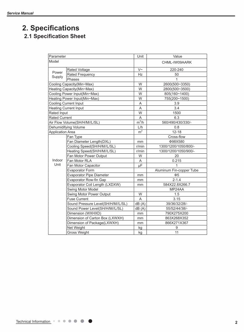
Parameter Unit ValueModel CHML-IW09AARK
Power Supply
Rated Voltage V~ 220-240Rated Frequency Hz 50
Phases 1
Cooling Capacity(Min~Max) W 2600(500~3350)Heating Capacity(Min~Max) W 2800(500~3500)Cooling Power Input(Min~Max) W 805(160~1400)Heating Power Input(Min~Max) W 755(200~1500)Cooling Current Input A 3.9
Heating Current Input A 3.4
Rated Input W 1500
Rated Current A 6.3
Air Flow Volume(SH/H/M//L/SL) m3/h 560/490/430/330/-Dehumidifying Volume L/h 0.8
Application Area m2 12-18
Indoor Unit
Fan Type Cross-flowFan Diameter Length(DXL) mm Ф98X580 Cooling Speed(SH/H/M//L/SL) r/min 1300/1200/1050/800/-Heating Speed(SH/H/M//L/SL) r/min 1300/1200/1050/900/-Fan Motor Power Output W 20
Fan Motor RLA A 0.215
Fan Motor Capacitor μF 1
Evaporator Form Aluminum Fin-copper TubeEvaporator Pipe Diameter mm Ф5Evaporator Row-fin Gap mm 2-1.4Evaporator Coil Length (LXDXW) mm 584X22.8X266.7 Swing Motor Model MP24AA Swing Motor Power Output W 1.5
Fuse Current A 3.15
Sound Pressure Level(SH/H/M//L/SL) dB (A) 39/36/32/28/-Sound Power Level(SH/H/M//L/SL) dB (A) 55/52/44/38/-Dimension (WXHXD) mm 790X275X200Dimension of Carton Box (LXWXH) mm 863X268X352Dimension of Package(LXWXH) mm 866X271X367Net Weight kg 9
Gross Weight kg 11
2. Specifications2.1 Specification Sheet
2Technical Information
Service Manual
3 Technical Information
Service Manual
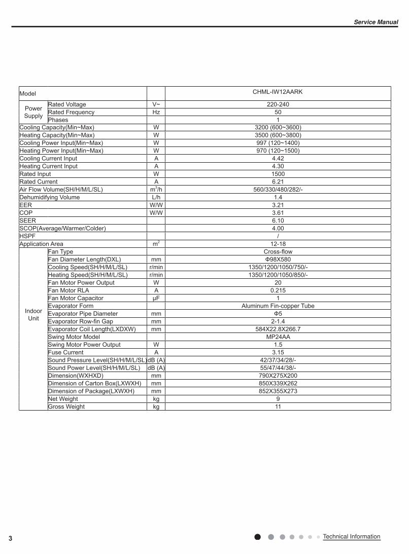
Model CHML-IW12AARK
Power Supply
Rated Voltage V~ 220-240Rated Frequency Hz 50
Phases 1
Cooling Capacity(Min~Max) W 3200 (600~3600)Heating Capacity(Min~Max) W 3500 (600~3800)Cooling Power Input(Min~Max) W 997 (120~1400)Heating Power Input(Min~Max) W 970 (120~1500)Cooling Current Input A 4.42
Heating Current Input A 4.30
Rated Input W 1500
Rated Current A 6.21
Air Flow Volume(SH/H/M/L/SL) m3/h 560/330/480/282/-Dehumidifying Volume L/h 1.4
EER W/W 3.21
COP W/W 3.61
SEER 6.10
SCOP(Average/Warmer/Colder) 4.00
HSPF /Application Area m2 12-18
Indoor Unit
Fan Type Cross-flowFan Diameter Length(DXL) mm Ф98X580Cooling Speed(SH/H/M/L/SL) r/min 1350/1200/1050/750/-Heating Speed(SH/H/M/L/SL) r/min 1350/1200/1050/850/-Fan Motor Power Output W 20
Fan Motor RLA A 0.215
Fan Motor Capacitor μF 1
Evaporator Form Aluminum Fin-copper TubeEvaporator Pipe Diameter mm Ф5Evaporator Row-fin Gap mm 2-1.4Evaporator Coil Length(LXDXW) mm 584X22.8X266.7 Swing Motor Model MP24AA Swing Motor Power Output W 1.5
Fuse Current A 3.15
Sound Pressure Level(SH/H/M/L/SL)dB (A) 42/37/34/28/-Sound Power Level(SH/H/M/L/SL) dB (A) 55/47/44/38/-Dimension(WXHXD) mm 790X275X200Dimension of Carton Box(LXWXH) mm 850X339X262Dimension of Package(LXWXH) mm 852X355X273Net Weight kg 9
Gross Weight kg 11

2.2 Operation Characteristic Curve
2.3 Capacity Variation Ratio According to Temperature
50
60
70
80
90
100
110
120
130
32 33 34 35 36 37 38 39 40 41 42 43 44 45 46
Capacity r
atio(%
)
Outdoor temp. (°C)
Capacity r
atio(%
)
gnitaeHgnilooC
gnitaeHgnilooC
-20 -15 -10 -5 0 5 10
110
120
130
100
90
80
70
60
50
40
Outdoor temp.(°C)
50
60
70
80
90
100
110
120
130
32 33 34 35 36 37 38 39 40 41 42 43 44 45 46
Capacity r
atio(%
)
Outdoor temp. (°C)
Capacity r
atio(%
)
–15 –10 –5
110
100
90
80
70
60
50
400 5 7 10
Conditions
Indoor:DB20°C
Indoor air flow:Super High
Pipe length:5m
Outdoor temp.(°C)
ConditionIndoor:DB27°C WB19°CIndoor air flow: HighPipe length:5m
ConditionIndoor:DB27°C WB19°CIndoor air flow: HighPipe length:5m
ConditionIndoor:DB20°CIndoor air flow: HighPipe length:5m
Heating operation ambient temperature range is -20ºC~24ºC
Heating operation ambient temperature range is -15ºC~24ºC
0 10 20 30 40 50 60 70 90 0 10 20 30 40 50 60 70 80 90 100 12011080
11
10
9
8
7
6
5
4
3
2
1
0
Compressor speed (rps)
)A(
tn
erru
C
11
10
9
8
7
6
5
4
3
2
1
0
Compressor speed (rps)
)A(
tn
erru
C
220V
230V
240V
220V
230V
240V
Conditions
Indoor: DB27°C/WB19°C
Outdoor: DB35°C/WB24°C
Indoor air flow: High
Pipe length: 5m
Conditions
Indoor: DB20°C/WB15°C
Outdoor: DB7°C/WB6°C
Indoor air flow: High
Pipe length: 5m
Cooling Heating
4Technical Information
Service Manual
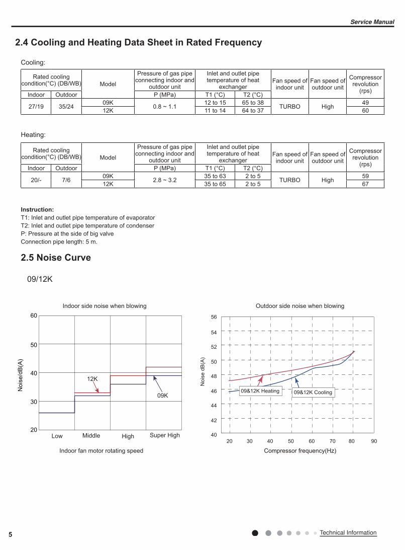
2.4 Cooling and Heating Data Sheet in Rated Frequency
2.5 Noise Curve
Indoor side noise when blowing Outdoor side noise when blowing
Indoor fan motor rotating speed Compressor frequency(Hz)
Nois
e/d
B(A
)
50
60
30
40
20Low Middle High Super High
12K
09K
40
42
44
46
48
50
52
54
56
20 4030 50 60 70 80 90
Nois
e d
B(A
)
09&12K Cooling09&12K Heating
Cooling:
Rated cooling condition(°C) (DB/WB) Model
Pressure of gas pipe connecting indoor and
outdoor unit
Inlet and outlet pipe temperature of heat
exchangerFan speed of
indoor unitFan speed of outdoor unit
Compressor revolution
(rps)Indoor Outdoor P (MPa) T1 (°C) T2 (°C)
27/19 35/24 09K0.8 ~ 1.1
12 to 15 65 to 38 TURBO High 49
12K 11 to 14 64 to 37 60
Instruction:
T1: Inlet and outlet pipe temperature of evaporatorT2: Inlet and outlet pipe temperature of condenserP: Pressure at the side of big valve Connection pipe length: 5 m.
Heating:
Rated cooling condition(°C) (DB/WB) Model
Pressure of gas pipe connecting indoor and
outdoor unit
Inlet and outlet pipe temperature of heat
exchangerFan speed of
indoor unitFan speed of outdoor unit
Compressor revolution
(rps)Indoor Outdoor P (MPa) T1 (°C) T2 (°C)
20/- 7/6 09K2.8 ~ 3.2
35 to 63 2 to 5 TURBO High 59
12K 35 to 65 2 to 5 67
09/12K
5 Technical Information
Service Manual
6Technical Information
Service Manual
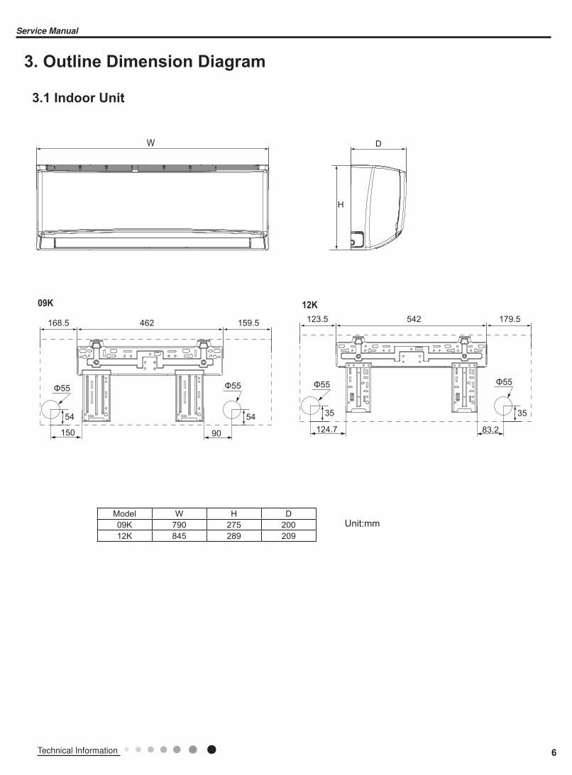
3. Outline Dimension Diagram
3.1 Indoor Unit
Unit:mmModel W H D09K 790 275 200
12K 845 289 209
W
12K09K
D
H
90150
54
168.5 462 159.5
Φ55 Φ55
54
123.5 542 179.5
83.2124.7
35
Φ55 Φ55
35
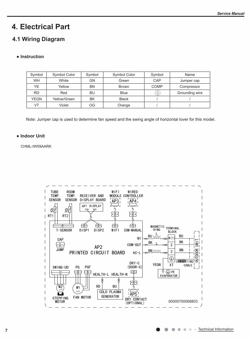
4. Electrical Part
4.1 Wiring Diagram
● Indoor Unit
● Instruction
Symbol Symbol Color Symbol Symbol Color Symbol NameWH White GN Green CAP Jumper capYE Yellow BN Brown COMP Compressor
RD Red BU Blue Grounding wire
YEGN Yellow/Green BK Black / /
VT Violet OG Orange / /
Note: Jumper cap is used to determine fan speed and the swing angle of horizontal lover for this model.
CHML-IW09AARK
60000700068803
7 Technical Information
Service Manual
8Technical Information
Service Manual
GWH09QB-K6DNE6C/I(CB465N00601) GWH09QB-K6DND4C/I(CB464N00302) GWH09QB-K6DND6C/I( CB460N03002)GWH09QB-K6DNB2C/I(CB432N12501) GWH12QC-K6DNB2C/I(CB432N14801)
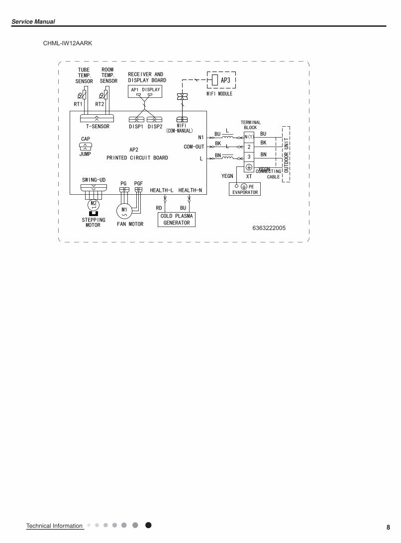
CHML-IW12AARK
6363222005
9 Technical Information
Service Manual
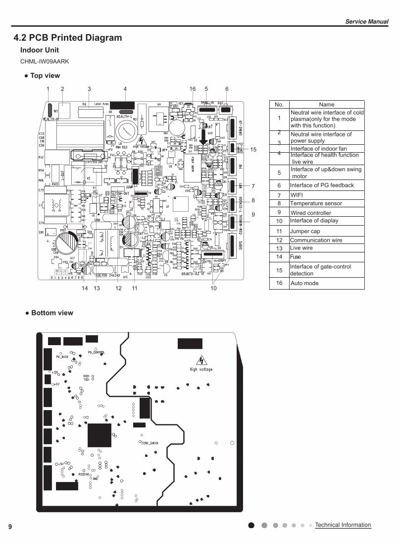
4.2 PCB Printed Diagram
Indoor Unit
1 2 4 516 6
7
8
9
15
1011121314
3
● Top view
● Bottom view
No. Name
1
2
3
4 Interface of health function
live wire
5Interface of up&down swing
motor
Interface of PG feedback 6
Neutral wire interface of cold plasma(only for the mode with this function)
7 WIFI
8 Temperature sensor
Wired controller9
10 Interface of diaplay
11
12 Communication wire
Jumper cap
13 Live wire
14 Fuse
15
16
Interface of gate-control
detection
Neutral wire interface of power supply
Interface of indoor fan
Auto mode
CHML-IW09AARK
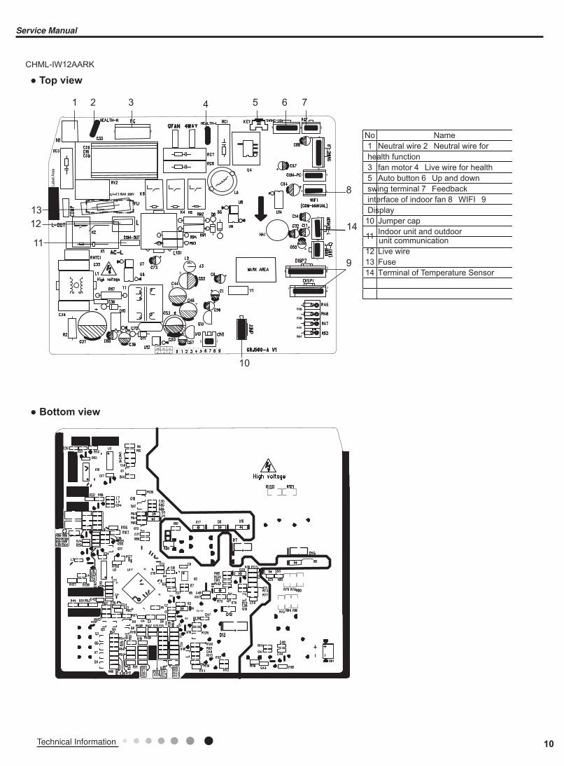
10Technical Information
Service Manual
11
12
13
1 2 3 4 5 6 7
8
14
9
10
No Name
1 Neutral wire 2 Neutral wire for
health function
3 fan motor 4 Live wire for health
5 Auto button 6 Up and down
swing terminal 7 Feedback
interface of indoor fan 8 WIFI 9
Display
10 Jumper cap
11Indoor unit and outdoorunit communication
12 Live wire
13 Fuse
14 Terminal of Temperature Sensor
CHML-IW12AARK
● Top view
● Bottom view

YAN1F6(WIFI)
Introduction for icons on display screen
Buttons on remote controller
Introduction for buttons on remote controller
5
3
6
8
10
12
11
9
7
4
2
1
1
2
3
4
5
6
7
8
9
10
11
12
ON/OFF button
MODE button
FAN button
SWING button
TURBO button
TEMP button
WiFi button
LIGHT button
CLOCK button
TIMER ON / TIMER OFFbutton
SLEEP button
▲/ button▲
Send signal
Turbo mode
8 heating function
Set temperature
WiFi function
Set time
TIMER ON /
TIMER OFF
Child lock
Up & down swing
Set fan speed
Light
Temp. display type:Set temp.
:Outdoor ambient temp.
:Indoor ambient temp.
Sleep mode
Clock
Heat mode
Fan mode
Dry mode
Cool mode
Auto mode
Operation mode
I feel
Temp. display type
Note:
● This is a general use remote controller, it could be used for the air conditioners with multifunction; For some function, which the model doesnt have, if press the corresponding button on the remote controller that the unit will keep the original running status.● After putting through the power, the air conditioner will give out a sound. Operation indictor " " is ON (red indicator. the colour is different for different models). After that,you can operate the air conditioner by using remote controller.● Under on status, pressing the button on the remote controller, the signal icon " "on the display of remote controller will blink once and the air conditioner will give out a “de” sound, which means the signal has been sent to the air conditioner.● Under off status, set temperature and clock icon will be displayed on the display of remote controller (If timer on, timer off and light functions are set, the corre- sponding icons will be displayed on the display of remote controller at the same time); Under on status, the display will show the corresponding set function icons.
5. Function and Control
5.1 Remote Controller Introduction
11 Technical Information
Service Manual
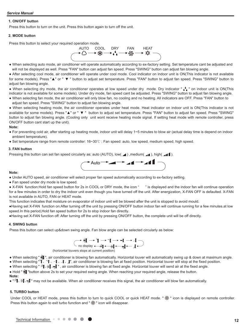
1. ON/OFF button
2. MODE button
3. FAN button
Press this button to turn on the unit. Press this button again to turn off the unit.
● When selecting auto mode, air conditioner will operate automatically according to ex-factory setting. Set temperature cant be adjusted and will not be displayed as well. Press "FAN" button can adjust fan speed. Press "SWING" button can adjust fan blowing angle.● After selecting cool mode, air conditioner will operate under cool mode. Cool indicator on indoor unit is ON(This indicator is not available for some models). Press "▲" or " ▲ " button to adjust set temperature. Press "FAN" button to adjust fan speed. Press "SWING" button to adjust fan blowing angle.● When selecting dry mode, the air conditioner operates at low speed under dry mode. Dry indicator " " on indoor unit is ON(This indicator is not available for some models). Under dry mode, fan speed cant be adjusted. Press "SWING" button to adjust fan blowing angle.● When selecting fan mode, the air conditioner will only blow fan, no cooling and no heating. All indicators are OFF. Press "FAN" button to adjust fan speed. Press "SWING" button to adjust fan blowing angle.● When selecting heating mode, the air conditioner operates under heat mode. Heat indicator on indoor unit is ON(This indicator is not available for some models). Press "▲" or " ▲ " button to adjust set temperature. Press "FAN" button to adjust fan speed. Press "SWING" button to adjust fan blowing angle. (Cooling only unit wont receive heating mode signal. If setting heat mode with remote controller, press ON/OFF button cant start up the unit).Note:
● For preventing cold air, after starting up heating mode, indoor unit will delay 1~5 minutes to blow air (actual delay time is depend on indoor ambient temperature).● Set temperature range from remote controller: 16~30℃ ; Fan speed: auto, low speed, medium speed, high speed.
5. TURBO button
Under COOL or HEAT mode, press this button to turn to quick COOL or quick HEAT mode. " " icon is displayed on remote controller. Press this button again to exit turbo function and " " icon will disappear.
Note:
● Under AUTO speed, air conditioner will select proper fan speed automatically according to ex-factory setting.● Fan speed under dry mode is low speed.● X-FAN function:Hold fan speed button for 2s in COOL or DRY mode, the icon “ ” is displayed and the indoor fan will continue operation for a few minutes in order to dry the indoor unit even though you have turned off the unit. After energization, X-FAN OFF is defaulted. X-FAN is not available in AUTO, FAN or HEAT mode.This function indicates that moisture on evaporator of indoor unit will be blowed after the unit is stopped to avoid mould.●Having set X-FAN function on:After turning off the unit by pressing ON/OFF button indoor fan will continue running for a few minutes.at lowspeed.In this period,Hold fan speed button for 2s to stop indoor fan directly.●Having set X-FAN function off: After turning off the unit by pressing ON/OFF button, the complete unit will be off directly.
Pressing this button can set fan speed circularly as: auto (AUTO), low( ) ,medium( ), high( ).
Press this button to select your required operation mode.AUTO COOL FANDRY HEAT
Auto
4. SWING button
Press this button can select up&down swing angle. Fan blow angle can be selected circularly as below:
● When selecting " ", air conditioner is blowing fan automatically. Horizontal louver will automatically swing up & down at maximum angle.● When selecting " 、 、 � � � � � � � � � � � � � � 、 、 ", air conditioner is blowing fan at fixed position. Horizontal louver will stop at the fixed position.● When selecting " 、 、 " , air conditioner is blowing fan at fixed angle. Horizontal louver will send air at the fixed angle.● Hold " "button above 2s to set your required swing angle. When reaching your required angle, release the button.Note:
● " 、
� � � � � � � � � � � � � � � 、 " may not be available. When air conditioner receives this signal, the air conditioner will blow fan automatically.
no display(horizontal louvers stops at current position)
12Technical Information
Service Manual

6. ▲/ ▲
button
● Press "▲" or " ▲" button once increase or decrease set temperature 1℃ . Holding "▲" or " ▲" button, 2s later, set temperature on remote controller will change quickly. On releasing button after setting is finished, temperature indicator on indoor unit will change accordingly. (Temperature cant be adjusted under auto mode)● When setting TIMER ON, TIMER OFF or CLOCK, press "▲" or "▲" button to adjust time. (Refer to CLOCK, TIMER ON, TIMER OFF buttons) When setting TIMER ON, TIMER OFF or CLOCK, press "▲" or "▲" button to adjust time. (Refer to CLOCK, TIMER ON, TIMER OFF buttons)
7. SLEEP button
9. WIFI button
10. LIGHT button
11. CLOCK button
12. TIMER ON / TIMER OFF button
Under COOL, HEAT or DRY mode, press this button to start up sleep function. " " icon is displayed on remote controller. Press this button again to cancel sleep function and " " icon will disappear.
Press " WiFi " button to turn on or turn off WiFi function. When WiFi function is turned on, the " WiFi " icon will be displayed on remote controller; Under status of remote controller off, press "MODE" and " WiFi " buttons simultaneously for 1s,WiFi modulewill restore to factory default setting.
Press this button to turn off display light on indoor unit. " " icon on remote controller disappears. Press this button again to turn on display light. " " icon is displayed.
Press this button to set clock time. " " icon on remote controller will blink. Press "▲" or " ▲" button within 5s to set clock time. Each
pressing of "▲" or " ▲" button, clock time will increase or decrease 1 minute. If hold "▲" or " ▲" button, 2s later, time will change quickly. Release this button when reaching your required time. Press "CLOCK" button to confirm the time. " " icon stops blinking.Note:
● Clock time adopts 24-hour mode.● The interval between two operation cant exceeds 5s. Otherwise, remote controller will quit setting status. Operation for TIMER ON/TIMER OFF is the same.
● TIMER ON button "TIMER ON" button can set the time for timer on. After pressing this button, " " icon disappears and the word "ON" on remote controller blinks. Press "▲" or " ▲"button to adjust TIMER ON setting. After each pressing "▲" or " ▲" button, TIMER ON setting will increase or decrease 1min. Hold "▲" or " ▲" button, 2s later, the time will change quickly until reaching your required time. Press "TIMER ON" to confirm it. The word "ON" will stop blinking. " " icon resumes displaying. Cancel TIMER ON: Under the condition that TIMER ON is started up, press "TIMER ON" button to cancel it.● TIMER OFF button "TIMER OFF" button can set the time for timer off. After pressing this button," " icon disappears and the word "OFF" on remote controller blinks. Press "▲" or " ▲" button to adjust TIMER OFF setting. After each pressing "▲" or " ▲" button, TIMER OFF setting will increase or decrease 1min. Hold "▲" or " ▲" button, 2s later, the time will change quickly until reaching your required time. Press "TIMER OFF" word "OFF" will stop blinking. " " icon resumes displaying. Cancel TIMER OFF. Under the condition that TIMER OFF is started up, press "TIMER OFF" button to cancel it.
8. TEMP button
By pressing this button, you can see indoor set temperature, indoor ambient temperature or outdoor ambient temperature on indoor units display. The setting on remote controlleris selected circularly as below:
● When selecting " " or no display with remote controller, temperature indicator on indoor unit displays set temperature.● When selecting " " with remote controller, temperature indicator on indoor unit displays indoor ambient temperature.● When selecting " " with remote controller, temperature indicator on indoor unit displays outdoor ambient temperature.Note:
● Outdoor temperature display is not available for some models. At that time, indoor unit receives " "signal, while it displays indoor set temperature.● Its defaulted to display set temperature when turning on the unit.There is no display in the remote controller.● Only for the models whose indoor unit has dual-8 display.● When selecting displaying of indoor or outdoor ambient temperature, indoor temperature indicator displays corresponding temperature and automatically turn to display set temperature after three or five seconds.
no display
13 Technical Information
Service Manual
Note:
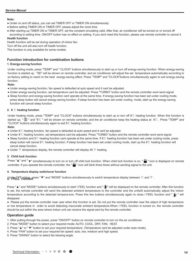
● Under on and off status, you can set TIMER OFF or TIMER ON simultaneously.● Before setting TIMER ON or TIMER OFF, please adjust the clock time.● After starting up TIMER ON or TIMER OFF, set the constant circulating valid. After that, air conditioner will be turned on or turned off according to setting time. ON/OFF button has no effect on setting. If you dont need this function, please use remote controller to cancel it.Health function
Health function will be set during operation of indoor fan.Turn off the unit will also turn off health function.This function is only available for some models.
Function introduction for combination buttons
1. Energy-saving function
2. 8 ℃ heating function
3. Child lock function
4. Temperature display switchover function
5. I FELL Function
Under cooling mode, press "TEMP" and " CLOCK" buttons simultaneously to start up or turn off energy-saving function. When energy-saving function is started up, "SE" will be shown on remote controller, and air conditioner will adjust the set temperature automatically according to ex-factory setting to reach to the best energy-saving effect. Press "TEMP" and "CLOCK"buttons simultaneously again to exit energy-saving function. Note:
● Under energy-saving function, fan speed is defaulted at auto speed and it cant be adjusted.● Under energy-saving function, set temperature cant be adjusted. Press "TURBO" button and the remote controller wont send signal.● Sleep function and energy-saving function cant operate at the same time. If energy-saving function has been set under cooling mode, press sleep button will cancel energy-saving function. If sleep function has been set under cooling mode, start up the energy-saving function will cancel sleep function.
Under heating mode, press "TEMP" and "CLOCK" buttons simultaneously to start up or turn off 8℃ heating function. When this function is started up, " " and "8℃ " will be shown on remote controller, and the air conditioner keep the heating status at 8℃ . Press "TEMP" and "CLOCK" buttons simultaneously again to exit 8℃ heating function.Note:
● Under 8℃ heating function, fan speed is defaulted at auto speed and it cant be adjusted.● Under 8℃ heating function, set temperature cant be adjusted. Press "TURBO" button and the remote controller wont send signal.● Sleep function and 8℃ heating function cant operate at the same time. If 8℃ heating function has been set under cooling mode, press sleep button will cancel 8℃ heating function. If sleep function has been set under cooling mode, start up the 8℃ heating function will cancel sleep function. ● Under ℉ temperature display, the remote controller will display 46℉ heating.
Press "▲" and " ▲" simultaneously to turn on or turn off child lock function. When child lock function is on, " " icon is displayed on remote controller. If you operate the remote controller, the " " icon will blink three times without sending signal to the unit.
Press "▲" and "MODE" buttons simultaneously to start I FEEL function and " " will be displayed on the remote controller. After this function is set, the remote controller will send the detected ambient temperature to the controller and the unitwill automatically adjust the indoor temperature according to the detected tempera-ture. Press this two buttons simultaneously again to close I FEEL function and " " will disappear.● Please put the remote controller near user when this function is set. Do not put the remote controller near the object of high temperature or low temperature in order to avoid detecting inaccurate ambient temperature.When I FEEL function is turned on, the remote controller should be put within the area where indoor unit can receive the signal sent by the remote controller.
Under OFF status, press " ▲" and "MODE" buttons simultaneously to switch temperature display between ℃ and ℉ .
Operation guide
1. After putting through the power, press "ON/OFF" button on remote controller to turn on the air conditioner.2. Press "MODE" button to select your required mode: AUTO, COOL, DRY, FAN, HEAT.3. Press "▲" or " ▲" button to set your required temperature. (Temperature cant be adjusted under auto mode).4. Press "FAN" button to set your required fan speed: auto, low, medium and high speed.5. Press "SWING" button to select fan blowing angle.
14Technical Information
Service Manual
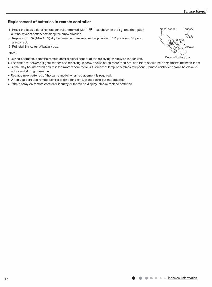
Replacement of batteries in remote controller
● During operation, point the remote control signal sender at the receiving window on indoor unit.● The distance between signal sender and receiving window should be no more than 8m, and there should be no obstacles between them.● Signal may be interfered easily in the room where there is fluorescent lamp or wireless telephone; remote controller should be close to indoor unit during operation.● Replace new batteries of the same model when replacement is required.● When you dont use remote controller for a long time, please take out the batteries.● If the display on remote controller is fuzzy or theres no display, please replace batteries.
1. Press the back side of remote controller marked with " ", as shown in the fig, and then push out the cover of battery box along the arrow direction.2. Replace two 7# (AAA 1.5V) dry batteries, and make sure the position of "+" polar and "-" polar are correct.3. Reinstall the cover of battery box.
Note:
signal sender battery
Cover of battery box
remove
reinstall
15 Technical Information
Service Manual

Control Flow Chart
Download and installation
Operating Systems
Requirement for User's smart phone:
Scan the QR code or search "Ewpe Smart" in the application market to download and install it. When "Ewpe Smart" App is installed, register the account and add the device to achieve long-distance control and LAN control of smart home appliances. For more information, please refer to "Help" in App.
5.2 Ewpe Smart App Operation Manual
iOS system
Support iOS7.0 and
above version
Android system
Support Android 4.4 and
above version
App Download Linkage
Internet
Cellular/
Other Wi-FI
Home Wi-Fi
Home wireless router
Home Wi-Fi
Cloud
APP
intelligenthome
appliances
16Technical Information
Service Manual
5.3 Brief Description of Modes and Functions
1.Basic function of system
(1)Cooling mode
(1) Under this mode, fan and swing operates at setting status. Temperature setting range is 16~30OC. (2) During malfunction of outdoor unit or the unit is stopped because of protection, indoor unit keeps original operation status.(2)Drying mode
(1) Under this mode, fan operates at low speed and swing operates at setting status. Temperature setting range is 16~30OC. (2) During malfunction of outdoor unit or the unit is stopped because of protection, indoor unit keeps original operation status. (3) Protection status is same as that under cooling mode.(4) Sleep function is not available for drying mode.(3)Heating mode
(1) Under this mode, Temperature setting range is 16~30OC. (2) Working condition and process for heating mode:When turn on the unit under heating mode, indoor unit enters into cold air prevention status. When the unit is stopped or at OFF status, and indoor unit has been started up just now, the unit enters into residual heat-blowing status.(4)Working method for AUTO mode:
1.Working condition and process for AUTO mode:a.Under AUTO mode, standard heating Tpreset=20OC and standard cooling Tpreset=25OC. The unit will switch mode automatically according to ambient temperature.2.Protection functiona. During cooling operation, protection function is same as that under cooling mode.b. During heating operation, protection function is same as that under heating mode.3. Display: Set temperature is the set value under each condition. Ambient temperature is (Tamb.-Tcompensation) for heat pump unit and Tamb. for cooling only unit. 4. If theres I feel function, Tcompensation is 0. Others are same as above.(5)Fan mode
Under this mode, indoor fan operates at set fan speed. Compressor, outdoor fan, 4-way valve and electric heating tube stop operation. Indoor fan can select to operate at high, medium, low or auto fan speed. Temperature setting range is 16~30OC.
2. Other control
(1) Buzzer
Upon energization or availably operating the unit or remote controller, the buzzer will give out a beep.(2) Auto button
If press this auto button when turning off the unit, the complete unit will operate at auto mode. Indoor fan operates at auto fan speed and swing function is turned on. Press this auto button at ON status to turn off the unit.(3) Auto fan
Heating mode: During auto heating mode or normal heating ode, auto fan speed will adjust the fan speed automatically according to ambient temperature and set temperature.(4) Sleep
After setting sleep function for a period of time, system will adjust set temperature automatically.(5) Timer function:
General timer and clock timer functions are compatible by equipping remote controller with different functions.(6) Memory function
memorize compensation temperature, off-peak energization value.Memory content: mode, up&down swing, light, set temperature, set fan speed, general timer (clock timer cant be memorized).After power recovery, the unit will be turned on automatically according to memory content.(7) Health function
During operation of indoor fan, set health function by remote controller. Turn off the unit will also turn off health function.Turn on the unit by pressing auto button, and the health is defaulted ON.
● Indoor Unit
17 Technical Information
Service Manual
(8)I feel control mode
After controller received I feel control signal and ambient temperature sent by remote controller, controller will work according to the ambient temperature sent by remote controller.(9)Entry condition for compulsory defrosting function
When turn on the unit under heating ode and set temperature is 16OC (or 16.5OC by remote controller), press “+, -, +, -, +, -” button successively within 5s and then indoor unit will enter into compulsory defrosting setting status:(1) If theres only indoor units controller, it enters into indoor normal defrosting mode.(2) If theres indoor units controller and outdoor units controller, indoor unit will send compulsory defrosting mode signal to outdoor unit and then outdoor unit will operate under normal defrosting mode. After indoor unit received the signal that outdoor unit has entered into defrosting status, indoor unit will cancel to send compulsory mode to outdoor unit. If outdoor unit hasnt received feedback signal from outdoor unit after 3min, indoor unit will also cancel to send compulsory defrosting signal.(10)Refrigerant recovery function:
Enter into Freon recovery mode actively: Within 5min after energization, turn on the unit at 16OC under cooling mode, and press light button for 3 times within 3s to enter into Freon recovery mode. Fo is displayed and Freon recovery mode will be sent to outdoor unit.(11)Ambient temperature display control mode
1. When user set the remote controller to display set temperature (corresponding remote control code: 01), current set temperature will be displayed. 2. Only when remote control signal is switched to indoor ambient temperature display status (corresponding remote control code: 10) from other display status (corresponding remote control code: 00, 01,11),controller will display indoor ambient temperature for 3s and then turn back to display set temperature.Under this mode, indoor fan operates at set fan speed. Compressor, outdoor fan, 4-way valve and electric heating tube stop operation. Indoor fan can select to operate at high, medium, low or auto fan speed. Temperature setting range is 16~30OC.
(12)Off-peak energization function:
Adjust compressors minimum stop time. The original minimum stop time is 180s and then we change to: The time interval between two start-ups of compressor cant be less than 180+Ts(0≤T≤15). T is the variable of controller. Thats to say the minimum stop time of compressor is 180s~195s. Read-in T into memory chip when refurbish the memory chip each time. After power recovery, compressor can only be started up after 180+T s at least.(13) SE control mode
The unit operates at SE status. (14) X-fan mode
When X-fan function is turned on, after turn off the unit, indoor fan will still operate at low speed for 2min and then the complete unit will be turned off. When x-fan function is turned off, after turn off the unit, the complete unit will be turned off directly.(15) 8
OC heating function
Under heating mode, you can set 8OC heating function by remote controller. The system will operate at 8OC set temperature. (16)Turbo function
Turbo function can be set under cooling and heating modes. Press Fan Speed button to cancel turbo setting. Turbo function is not availableunder auto, drying and fan modes.
18Technical Information
Service Manual
Part Ⅱ : Installation and Maintenance
1. Select the installation location according to the require-
ment of this manual.(See the requirements in installation
part)
2. Handle unit transportation with care; the unit should not
be carried by only one person if it is more than 20kg.
3. When installing the indoor unit and outdoor unit, a suffi-
cient fixing bolt must be installed; make sure the installation support is firm.4. Ware safety belt if the height of working is above 2m.
5. Use equipped components or appointed components dur-
ing installation.
6. Make sure no foreign objects are left in the unit after fin-
ishing installation.
Electrical Safety Precautions:
6. Notes for Installation and Maintenance
Safety Precautions:
Important!Please read the safety precautions carefully before
installation and maintenance.
The following contents are very important for installation
and maintenance.
Please follow the instructions below.
●The installation or maintenance must accord with the instructions.
●Comply with all national electrical codes and local electrical codes.
●Pay attention to the warnings and cautions in this manual.
●All installation and maintenance shall be performed by distributor or qualified person.●All electric work must be performed by a licensed technician according to local regulations and the
instructions given in this manual.
●Be caution during installation and maintenance. Prohibit incorrect operation to prevent electric shock, casualty and
other accidents.
1. Cut off the power supply of air conditioner before
checking and maintenance.
2. The air condition must apply specialized circuit and
prohibit share the same circuit with other appliances.
3. The air conditioner should be installed in suitable
location and ensure the power plug is touchable.
4. Make sure each wiring terminal is connected firmly
during installation and maintenance.
5. Have the unit adequately grounded. The grounding
wire cant be used for other purposes.
6. Must apply protective accessories such as protective
boards, cable-cross loop and wire clip.
7. The live wire, neutral wire and grounding wire of
power supply must be corresponding to the live wire,
neutral wire and grounding wire of the air conditioner.
8. The power cord and power connection wires cant be
pressed by hard objects.
9. If power cord or connection wire is broken, it must be
replaced by a qualified person.
Warnings
Improper installation may lead to fire hazard, explosion, electric shock or injury.
Installation Safety Precautions:
10. If the power cord or connection wire is not long enough,
please get the specialized power cord or connection wire
from the manufacture or distributor. Prohibit prolong the wire
by yourself.
11. For the air conditioner without plug, an air switch must
be installed in the circuit. The air switch should be all-pole
parting and the contact parting distance should be more than
3mm.
12. Make sure all wires and pipes are connected properly and
the valves are opened before energizing.
13. Check if there is electric leakage on the unit body. If yes,
please eliminate the electric leakage.
14. Replace the fuse with a new one of the same specification if it is burnt down; dont replace it with a cooper wire or
conducting wire.
15. If the unit is to be installed in a humid place, the circuit
breaker must be installed.
19 Technical Information
Service Manual

Safety Precautions for Installing and Relocating the Unit:
Warnings
To ensure safety, please be mindful of the following precautions.
1. When installing or relocating the unit, be sure to keep the refrigerant circuit free from air or substances other than the
specified refrigerant.Any presence of air or other foreign substance in the refrigerant circuit will cause system pressure rise or compressor rupture, resulting in injury.2.When installing or moving this unit, do not charge the refrigerant which is not comply with that on the nameplate or
unqualified refrigerant.Otherwise, it may cause abnormal operation, wrong action, mechanical malfunction or even series safety accident.3.When refrigerant needs to be recovered during relocating or repairing the unit, be sure that the unit is running in cooling
mode.Then, fully close the valve at high pressure side (liquid valve).About 30-40 seconds later, fully close the valve at low
pressure side (gas valve), immediately stop the unit and disconnect power. Please note that the time for refrigerant recovery
should not exceed 1 minute.
If refrigerant recovery takes too much time, air may be sucked in and cause pressure rise or compressor rupture, resulting in injury. 4.During refrigerant recovery, make sure that liquid valve and gas valve are fully closed and power is disconnected before
detaching the connection pipe.
If compressor starts running when stop valve is open and connection pipe is not yet connected, air will be sucked in and cause pressure rise or compressor rupture, resulting in injury.5.When installing the unit, make sure that connection pipe is securely connected before the compressor starts running.
If compressor starts running when stop valve is open and connection pipe is not yet connected, air will be sucked in and cause pressure rise or compressor rupture, resulting in injury.6.Prohibit installing the unit at the place where there may be leaked corrosive gas or flammable gas.If there leaked gas around the unit, it may cause explosion and other accidents.7.Do not use extension cords for electrical connections. If the electric wire is not long enough, please contact a local service
center authorized and ask for a proper electric wire.
Poor connections may lead to electric shock or fire.8.Use the specified types of wires for electrical connections between the indoor and outdoor units. Firmly clamp the wires so that their terminals receive no external stresses.
Electric wires with insufficient capacity, wrong wire connections and insecure wire terminals may cause electric shock or fire.
Safety Precautions for Refrigerant●To realize the function of the air conditioner unit, a special refrigerant circulates in the system. The used refrigerant is the fluoride R32,which is specially cleaned. The refrigerant is flammable and inodorous. Furthermore, it can leads to explosion under certain conditions. But the flammability of the refrigerant is very low. It can be ignited only by fire.●Compared to common refrigerants, R32 is a nonpolluting refrigerant with no harm to the ozonosphere. The influence upon the greenhouse effect is also lower. R32 has got very good thermodynamic features which lead to a really high energy
efficiency. The units therefore need a less filling.
WARNING:●Do not use means to accelerate the defrosting process or to clean, other than those recommended by the manufacture.Should repair be necessary,contact your nearest authorized Service Centre. Any repairs carried out by unqualified personnel may be dangerous. The appliance shall be stored in a room without continuously operating ignition sources. (for
example:open flames , an operating gas appliance or an operating electric heater.)●Do not pierce or burn.●Appliance shall be installed, operated and stored in a room with a floor area larger than 4m (or 6m ).●Appliance filled with flammable gas R32. For repairs, strictly follow manufacturers instructions only.Be aware that refrigrants not contain odour.
●Read specialists manual.
20Technical Information
Service Manual

Safety Operation of Flammable RefrigerantQualification requirement for installation and maintenance man●All the work men who are engaging in the refrigeration system should bear the valid certification awarded by the authoritative organization and the qualification for dealing with the refrigeration system recognized by this industry. If it needs other technician to maintain and repair the appliance, they should be supervised by the person who bears the qualification for using the flammable refrigerant.●It can only be repaired by the method suggested by the equipments manufacturer.
Installation notes
●The air conditioner is not allowed to use in a room that has running fire (such as fire source,working coal gas ware, operating heater).
●It is not allowed to drill hole or burn the connection pipe.●The air conditioner must be installed in a room that is larger than the minimum room area.The minimum room area is shown on the nameplate or following table a.
●Leak test is a must after installation.table a - Minimum room area(m
2)
Maintenance notes
●Check whether the maintenance area or the room area meet the requirement of the nameplate.— Its only allowed to be operated in the rooms that meet the requirement of the nameplate.
●Check whether the maintenance area is well-ventilated.— The continuous ventilation status should be kept during the operation process.
●Check whether there is fire source or potential fire source in the maintenance area.— The naked flame is prohibited in the maintenance area; and the “no smoking” warning board should be hanged.●Check whether the appliance mark is in good condition.— Replace the vague or damaged warning mark.
Welding
●If you should cut or weld the refrigerant system pipes in the process of maintaining, please follow the steps as below:a. Shut down the unit and cut power supply
b. Eliminate the refrigerant
c. Vacuuming
d. Clean it with N2 gas
e. Cutting or welding
f. Carry back to the service spot for welding
●Make sure that there isnt any naked flame near the outlet of the vacuum pump and its well-ventilated.●The refrigerant should be recycled into the specialized storage tank.
Filling the refrigerant
●Use the refrigerant filling appliances specialized for R32. Make sure that different kinds of refrigerant wont contaminate with each other.
●The refrigerant tank should be kept upright at the time of filling refrigerant.●Stick the label on the system after filling is finished (or havent finished).●Dont overfilling.●After filling is finished, please do the leakage detection before test running; another time of leak detection should be done when its removed.
Safety instructions for transportation and storage
●Please use the flammable gas detector to check before unload and open the container.●No fire source and smoking.●According to the local rules and laws.
21 Technical Information
Service Manual

Main Tools for Installation and Maintenance
1. Level meter, measuring tape
4. Electroprobe
7. Electronic leakage detector
10. Pipe pliers, pipe cutter
2. Screw driver
5. Universal meter
8. Vacuum pump
11. Pipe expander, pipe bender
3. Impact drill, drill head, electric drill
6. Torque wrench, open-end wrench, inner
hexagon spanner
9. Pressure meter
12. Soldering appliance, refrigerant container
22Technical Information
Service Manual

7. Installation
7.1 Installation Dimension Diagram
At l
east
250
cm
At l
east
15c
m
At least 300cm
Spa
ce to
the
floor
Spa
ce to
the
ceili
ng
Space to the obstruction
At least 15cmAt least 15cm
Space to the wall
Space to the wall
23 Technical Information
Service Manual
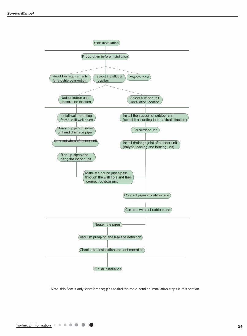
Preparation before installation
Prepare toolsRead the requirements
for electric connection
select installation
location
Select indoor unit
installation location
Install wall-mounting
frame, drill wall holes
Connect pipes of indoor
unit and drainage pipe
Connect wires of indoor unit
Connect wires of outdoor unit
Bind up pipes and
hang the indoor unit
Make the bound pipes pass
through the wall hole and then
connect outdoor unit
Neaten the pipes
Vacuum pumping and leakage detection
Check after installation and test operation
Finish installation
Note: this flow is only for reference; please find the more detailed installation steps in this section.
Select outdoor unit
installation location
Install the support of outdoor unit
(select it according to the actual situation)
Install drainage joint of outdoor unit
(only for cooling and heating unit)
Connect pipes of outdoor unit
Start installation
Fix outdoor unit
24Technical Information
Service Manual
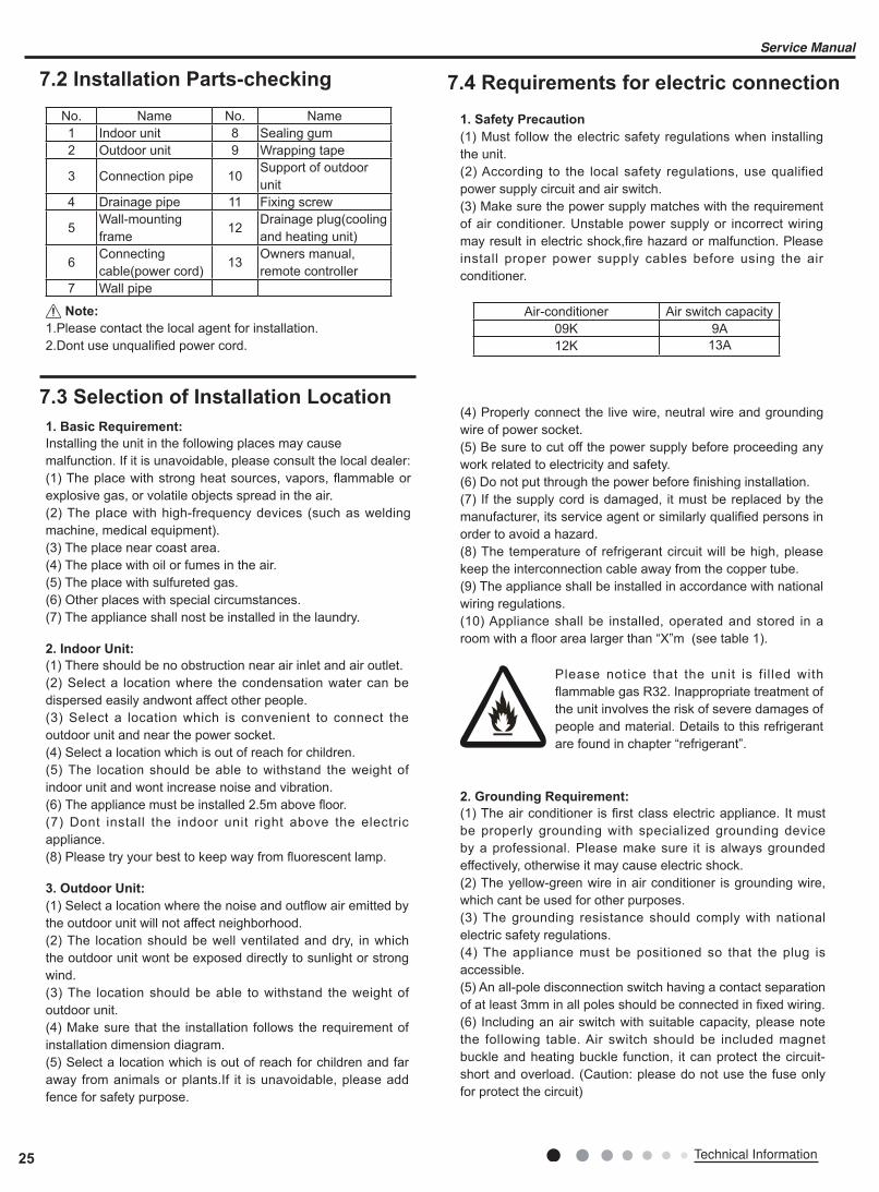
No. Name No. Name1 Indoor unit 8 Sealing gum2 Outdoor unit 9 Wrapping tape
3 Connection pipe 10Support of outdoor unit
4 Drainage pipe 11 Fixing screw
5Wall-mounting frame
12Drainage plug(cooling and heating unit)
6Connecting cable(power cord)
13Owners manual, remote controller
7 Wall pipe
7.2 Installation Parts-checking
7.3 Selection of Installation Location
1.Please contact the local agent for installation.2.Dont use unqualified power cord.
1. Basic Requirement:
Installing the unit in the following places may cause malfunction. If it is unavoidable, please consult the local dealer:(1) The place with strong heat sources, vapors, flammable or explosive gas, or volatile objects spread in the air.(2) The place with high-frequency devices (such as welding machine, medical equipment).(3) The place near coast area.(4) The place with oil or fumes in the air. (5) The place with sulfureted gas.(6) Other places with special circumstances.(7) The appliance shall nost be installed in the laundry.
2. Indoor Unit:
(1) There should be no obstruction near air inlet and air outlet.(2) Select a location where the condensation water can be dispersed easily andwont affect other people.(3) Select a location which is convenient to connect the outdoor unit and near the power socket.(4) Select a location which is out of reach for children.(5) The location should be able to withstand the weight of indoor unit and wont increase noise and vibration.(6) The appliance must be installed 2.5m above floor.(7) Dont install the indoor unit right above the electric appliance.(8) Please try your best to keep way from fluorescent lamp.
3. Outdoor Unit:
(1) Select a location where the noise and outflow air emitted by the outdoor unit will not affect neighborhood.(2) The location should be well ventilated and dry, in which the outdoor unit wont be exposed directly to sunlight or strong wind.(3) The location should be able to withstand the weight of outdoor unit.(4) Make sure that the installation follows the requirement of installation dimension diagram.(5) Select a location which is out of reach for children and far away from animals or plants.If it is unavoidable, please add fence for safety purpose.
Note:
1. Safety Precaution
(1) Must follow the electric safety regulations when installing the unit.(2) According to the local safety regulations, use qualified power supply circuit and air switch.(3) Make sure the power supply matches with the requirement of air conditioner. Unstable power supply or incorrect wiring may result in electric shock,fire hazard or malfunction. Please install proper power supply cables before using the air conditioner.
(4) Properly connect the live wire, neutral wire and grounding wire of power socket.(5) Be sure to cut off the power supply before proceeding any work related to electricity and safety.(6) Do not put through the power before finishing installation.(7) If the supply cord is damaged, it must be replaced by the manufacturer, its service agent or similarly qualified persons in order to avoid a hazard.(8) The temperature of refrigerant circuit will be high, please keep the interconnection cable away from the copper tube.(9) The appliance shall be installed in accordance with national wiring regulations.(10) Appliance shall be installed, operated and stored in a room with a floor area larger than “X”m (see table 1).
Air-conditioner Air switch capacity09K 9A12K 13A
2. Grounding Requirement:
(1) The air conditioner is first class electric appliance. It must be properly grounding with specialized grounding device by a professional. Please make sure it is always grounded effectively, otherwise it may cause electric shock.(2) The yellow-green wire in air conditioner is grounding wire, which cant be used for other purposes.(3) The grounding resistance should comply with national electric safety regulations.(4) The appliance must be positioned so that the plug is accessible.(5) An all-pole disconnection switch having a contact separation of at least 3mm in all poles should be connected in fixed wiring.(6) Including an air switch with suitable capacity, please note the following table. Air switch should be included magnet buckle and heating buckle function, it can protect the circuit-short and overload. (Caution: please do not use the fuse only for protect the circuit)
Please notice that the unit is fi l led with flammable gas R32. Inappropriate treatment of the unit involves the risk of severe damages of people and material. Details to this refrigerant are found in chapter “refrigerant”.
7.4 Requirements for electric connection
25 Technical Information
Service Manual
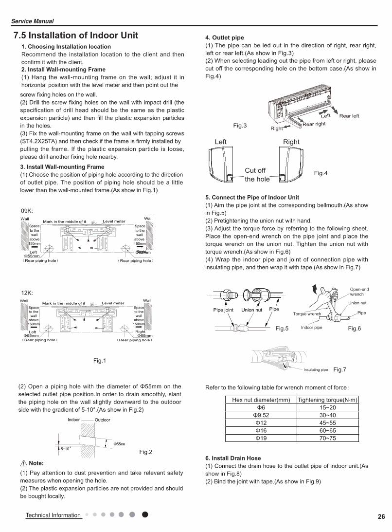
7.5 Installation of Indoor Unit1. Choosing Installation Iocation
Recommend the installation location to the client and then confirm it with the client.2. Install Wall-mounting Frame
(1) Hang the wall-mounting frame on the wall; adjust it in horizontal position with the level meter and then point out the
Left Rear left
RightRear right
Cut off
the hole
Left Right
5-10°Φ55mm
Indoor Outdoor
(1) Pay attention to dust prevention and take relevant safety measures when opening the hole.(2) The plastic expansion particles are not provided and should be bought locally.
Fig.1
Fig.2
Fig.3
Fig.43. Install Wall-mounting Frame
(1) Choose the position of piping hole according to the direction of outlet pipe. The position of piping hole should be a little lower than the wall-mounted frame.(As show in Fig.1)
4. Outlet pipe
(1) The pipe can be led out in the direction of right, rear right, left or rear left.(As show in Fig.3)(2) When selecting leading out the pipe from left or right, please cut off the corresponding hole on the bottom case.(As show in Fig.4)
(2) Open a piping hole with the diameter of Φ55mm on the selected outlet pipe position.In order to drain smoothly, slant the piping hole on the wall slightly downward to the outdoor side with the gradient of 5-10°.(As show in Fig.2)
Note:
Left
Wall
Φ55mmRight
Mark in the middle of it Level meter
Rear piping hole
Wall
Space
to the
wall
above
150mm
Space
to the
wall
above
150mm
Φ55mm
Rear piping hole
12K:
09K:
Left
Wall
Φ55mmRight
Mark in the middle of it Level meter
Rear piping hole
Wall
Space
to the
wall
above
150mm
Space
to the
wall
above
150mm
Φ55mm
Rear piping hole
Insulating pipe
Torque wrench
Open-end
wrench
Indoor pipe
Pipe
Union nut
Union nutPipe joint Pipe
Hex nut diameter(mm) Tightening torque(N.m)Φ6 15~20
Φ9.52 30~40
Φ12 45~55
Φ16 60~65
Φ19 70~75
Refer to the following table for wrench moment of force:
Fig.5 Fig.6
Fig.7
5. Connect the Pipe of Indoor Unit
(1) Aim the pipe joint at the corresponding bellmouth.(As show in Fig.5)(2) Pretightening the union nut with hand.(3) Adjust the torque force by referring to the following sheet. Place the open-end wrench on the pipe joint and place the torque wrench on the union nut. Tighten the union nut with torque wrench.(As show in Fig.6) (4) Wrap the indoor pipe and joint of connection pipe with insulating pipe, and then wrap it with tape.(As show in Fig.7)
6. Install Drain Hose
(1) Connect the drain hose to the outlet pipe of indoor unit.(As show in Fig.8)(2) Bind the joint with tape.(As show in Fig.9)
screw fixing holes on the wall.(2) Drill the screw fixing holes on the wall with impact drill (the specification of drill head should be the same as the plastic expansion particle) and then fill the plastic expansion particles in the holes.(3) Fix the wall-mounting frame on the wall with tapping screws (ST4.2X25TA) and then check if the frame is firmly installed bypulling the frame. If the plastic expansion particle is loose, please drill another fixing hole nearby.
26Technical Information
Service Manual
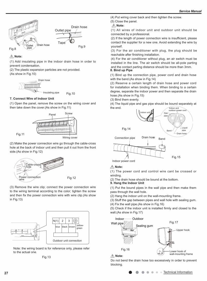
(4) Put wiring cover back and then tighten the screw.(5) Close the panel.
Indoor unit Gas
pipe
Indoor andoutdoor power cord
Liquid
pipe
Drain hose
Band
Drain hoseBandConnection pipe
Indoor power cord
Power connectionwire
Cable-crosshole
(1) All wires of indoor unit and outdoor unit should be connected by a professional.(2) If the length of power connection wire is insufficient, please contact the supplier for a new one. Avoid extending the wire by yourself. (3) For the air conditioner with plug, the plug should be reachable after finishing installation.(4) For the air conditioner without plug, an air switch must be installed in the line. The air switch should be all-pole parting and the contact parting distance should be more than 3mm.
(1) The power cord and control wire cant be crossed or winding.(2) The drain hose should be bound at the bottom.
7. Connect Wire of Indoor Unit
(1) Open the panel, remove the screw on the wiring cover and then take down the cover.(As show in Fig.11)
8. Bind up Pipe
(1) Bind up the connection pipe, power cord and drain hose with the band.(As show in Fig.14)(2) Reserve a certain length of drain hose and power cord for installation when binding them. When binding to a certain degree, separate the indoor power and then separate the drain hose.(As show in Fig.15)(3) Bind them evenly.(4) The liquid pipe and gas pipe should be bound separately at the end.
9. Hang the Indoor Unit
(1) Put the bound pipes in the wall pipe and then make them pass through the wall hole.(2) Hang the indoor unit on the wall-mounting frame.(3) Stuff the gap between pipes and wall hole with sealing gum.(4) Fix the wall pipe.(As show in Fig.16)(5) Check if the indoor unit is installed firmly and closed to the wall.(As show in Fig.17)
(2) Make the power connection wire go through the cable-cross hole at the back of indoor unit and then pull it out from the front side.(As show in Fig.12)
(3) Remove the wire clip; connect the power connection wire to the wiring terminal according to the color; tighten the screw and then fix the power connection wire with wire clip.(As show in Fig.13)
Note:
Note:
Fig.11
Fig.12
Fig.13
Fig.14
Fig.15
Outletpipe
Drain hose
Drain hose
Tape
Outlet pipe
Drain hose
Insulating pipe
(1) Add insulating pipe in the indoor drain hose in order to prevent condensation.(2) The plastic expansion particles are not provided.(As show in Fig.10)
Fig.8Fig.9
Fig.10
Note:
Wiring cover
ScrewPanel
N(1) 2 3
blue brownblackyellow-
green
Outdoor unit connection
Note: the wiring board is for reference only, please refer to the actual one.
Do not bend the drain hose too excessively in order to prevent blocking.
Note:
Indoor Outdoor
Wall pipeSealing gum
Upper hook
Lower hook ofwall-mounting frame
Fig.16
Fig.17
27 Technical Information
Service Manual
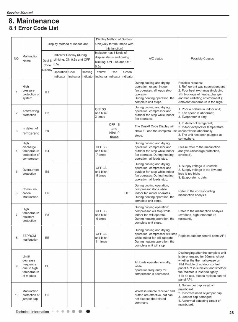
8. Maintenance8.1 Error Code List
NO.MalfunctionName
Display Method of Indoor UnitDisplay Method of Outdoor Unit(Only for the mode with
this function)
A/C status Possible Causes Dual-8Code
Display
Indicator Display (during blinking, ON 0.5s and OFF 0.5s)
Indicator has 3 kinds of display status and during blinking, ON 0.5s and OFF 0.5s
OperationIndicator
CoolIndicator
HeatingIndicator
YellowIndicator
RedIndicator
GreenIndicator
1
High pressureprotection of system
E1
During cooling and dryingoperation, except indoor fan operates, all loads stop operation.During heating operation, the complete unit stops.
Possible reasons: 1. Refrigerant was superabundant; 2. Poor heat exchange (including filth blockage of heat exchanger and bad radiating environment );Ambient temperature is too high.
2Antifreezingprotection E2
OFF 3Sand blink3 times
During cooling and dryingoperation, compressor andoutdoor fan stop while indoor fan operates.
1. Poor air-return in indoor unit;2. Fan speed is abnormal;3. Evaporator is dirty.
3In defect of refrigerant
F0
OFF 1Sand
blink 9times
The Dual-8 Code Display will show F0 and the complete unit stops.
1. In defect of refrigerant; 2. Indoor evaporator temperature sensor works abnormally;3. The unit has been plugged up somewhere.
4
High dischargetemperatureprotection ofcompressor
E4OFF 3Sand blink 7 times
During cooling and dryingoperation, compressor andoutdoor fan stop while indoor fan operates. During heatingoperation, all loads stop.
Please refer to the malfunction analysis (discharge protection, overload).
5Overcurrentprotection E5
OFF 3Sand blink 5 times
During cooling and dryingoperation, compressor andoutdoor fan stop while indoor fan operates. During heatingoperation, all loads stop.
1. Supply voltage is unstable;2. Supply voltage is too low and load is too high;3. Evaporator is dirty.
6
Communi-cationMalfunction
E6 OFF
During cooling operation,compressor stops while indoor fan motor operates. During heating operation, the complete unit stops.
Refer to the corresponding malfunction analysis.
7
Hightemperatureresistantprotection
E8OFF 3Sand blink 6 times
During cooling operation:compressor will stop while indoor fan will operate. During heating operation, the complete unit stops.
Refer to the malfunction analysis (overload, high temperature resistant).
8EEPROMmalfunction EE
OFF 3Sand blink11 times
During cooling and dryingoperation, compressor will stopwhile indoor fan will operate;During heating operation, thecomplete unit will stop
Replace outdoor control panel AP1
9
Limit/decreasefrequency due to hightemperature of module
EUAll loads operate normally, whileoperation frequency forcompressor is decreased
Discharging after the complete unit is de-energized for 20mins, check whether the thermal grease onIPM Module of outdoor control panel AP1 is sufficient and whether the radiator is inserted tightly.If its no use, please replace control panel AP1.
10
Malfunctionprotection ofjumper cap
C5Wireless remote receiver andbutton are effective, but cannot dispose the relatedcommand
1. No jumper cap insert onmainboard.2. Incorrect insert of jumper cap.3. Jumper cap damaged.4. Abnormal detecting circuit ofmainboard.
28Technical Information
Service Manual

NO.MalfunctionName
Display Method of Indoor UnitDisplay Method of Outdoor Unit(Only for the mode with
this function)
A/C status Possible Causes Dual-8Code
Display
Indicator Display (during blinking, ON 0.5s and OFF 0.5s)
Indicator has 3 kinds of display status and during blinking, ON 0.5s and OFF 0.5s
OperationIndicator
CoolIndicator
HeatingIndicator
YellowIndicator
RedIndicator
GreenIndicator
11Gathering refrigerant Fo
When the outdoor unit receive signal of Gathering refrigerant ,the system will be forced to run under cooling mode for gathering refrigerant
Nominal cooling mode
12
Indoor ambienttemperaturesensor isopen/short circuited
F1
During cooling and dryingoperation, indoor unit operateswhile other loads will stop; during heating operation, the complete unit will stop operation.
1. Loosening or bad contact ofindoor ambient temp. sensor andmainboard terminal.2. Components in mainboard felldown leads short circuit.3. Indoor ambient temp. sensordamaged.(check with sensorresistance value chart)4. Mainboard damaged.
13
Indoorevaporatortemperaturesensor isopen/shortcircuited
F2
AC stops operation oncereaches the settingtemperature. Cooling, drying:internal fan motor stopsoperation while other loadsstop operation; heating: ACstop operation
1. Loosening or bad contact of Indoorevaporator temp. sensor andmainboard terminal.2. Components on the mainboard falldown leads short circuit.3. Indoor evaporator temp. sensordamaged.(check temp. sensor valuechart for testing)4. Mainboard damaged.
14
Outdoor ambienttemperaturesensor isopen/shortcircuited
F3
OFF 3Sand blink
6 times
During cooling and dryingoperating, compressor stops while indoor fan operates; During heating operation, the complete unit will stop operation
Outdoor temperature sensor hasnt been connected well or is damaged. Please check it by referring to the resistance table for temperature sensor)
15
Outdoorcondensertemperaturesensor isopen/shortcircuited
F4
OFF 3Sand blink
5 times
During cooling and dryingoperation, compressor stops while indoor fan will operate; During heating operation, the complete unit will stop operation.
Outdoor temperature sensor hasnt been connected well or is damaged. Please check it by referring to the resistance table for temperature sensor)
16
Outdoordischargetemperaturesensor isopen/shortcircuited
F5
OFF 3Sand blink
7 times
During cooling and dryingoperation, compressor will sopafter operating for about 3 mins,while indoor fan will operate;During heating operation, thecomplete unit will stop afteroperating for about 3 mins.
1.Outdoor temperature sensor hasnt been connected well or is damaged. Please check it byreferring to the resistance table for temperature sensor)2.The head of temperature sensor hasnt been inserted into the copper tube
17
Limit/decreasefrequency due tooverload
F6
OFF 3Sand blink
3 times
All loads operate normally, whileoperation frequency forcompressor is decreased
Refer to the malfunction analysis (overload, high temperature resistant)
18
Decreasefrequency due toovercurrent
F8
OFF 3Sand blinkonce
All loads operate normally, whileoperation frequency forcompressor is decreased
The input supply voltage is too low;System pressure is too high and overload
29 Technical Information
Service Manual

NO.MalfunctionName
Display Method of Indoor UnitDisplay Method of Outdoor Unit(Only for the mode with
this function)
A/C status Possible Causes Dual-8Code
Display
Indicator Display (during blinking, ON 0.5s and OFF 0.5s)
Indicator has 3 kinds of display status and during blinking, ON 0.5s and OFF 0.5s
OperationIndicator
CoolIndicator
HeatingIndicator
YellowIndicator
RedIndicator
GreenIndicator
19
Decreasefrequency due tohigh airdischarge
F9
OFF 3Sand blinktwice
All loads operate normally, whileoperation frequency forcompressor is decreased
Overload or temperature is too high; Refrigerant is insufficient;Malfunction of electric expansion valve (EKV)
20
Limit/decreasefrequency due toantifreezing
FH
OFF 3Sand blink
4 times
All loads operate normally, while operation frequency for compressor is decreased
Poor air-return in indoor unit or fan speed is too low
21
Voltage for DC bus-bar is too high
PH
OFF 3Sand blink
13 times
During cooling and dryingoperation, compressor will stopwhile indoor fan will operate;During heating operation, thecomplete unit will stop operation.
1. Measure the voltage of position L and N on wiring board (XT), if the voltage is higher than 265VAC, turn on the unit after the supply voltage is increased to the normal range.2.If the AC input is normal, measure the voltage of electrolytic capacitor C on control panel (AP1), if its normal, theres malfunction for the circuit, please replace the control panel (AP1)
22
Voltage of DC bus-bar is too low
PL
OFF 3Sand blink
12 times
During cooling and dryingoperation, compressor will stopwhile indoor fan will operate;During heating operation, thecomplete unit will stop
1. Measure the voltage of position L and N on wiring board (XT), if the voltage is higher than 150VAC,turn on the unit after the supply voltage is increased to the normal range.2.If the AC input is normal, measure the voltage of electrolytic capacitor C on control panel (AP1), if its normal, theres malfunction for the circuit, please replace the control panel (AP1)
23
Compressor Min frequence in test state
P0Showing during min. cooling or min. heating test
24
Compressor rated frequence in test state
P1Showing during nominal cooling or nominal heating test
25
Compressor maximum frequence in test state
P2Showing during max. cooling or max. heating test
30Technical Information
Service Manual

NO.MalfunctionName
Display Method of Indoor UnitDisplay Method of Outdoor Unit(Only for the mode with
this function)
A/C status Possible Causes Dual-8Code
Display
Indicator Display (during blinking, ON 0.5s and OFF 0.5s)
Indicator has 3 kinds of display status and during blinking, ON 0.5s and OFF 0.5s
OperationIndicator
CoolIndicator
HeatingIndicator
YellowIndicator
RedIndicator
GreenIndicator
26
Compressor intermediate frequence in test state
P3Showing during middle cooling or middle heating test
27
Overcurrentprotection ofphase current for compressor
P5
During cooling and dryingoperation, compressor will stopwhile indoor fan will operate;During heating operation, thecomplete unit will stop operation.
Refer to the malfunction analysis (IPM protection, loss of synchronism protection and overcurrent protection of phase current for compressor.
28
Chargingmalfunction of capacitor
PU
During cooling and dryingoperation, compressor will stopwhile indoor fan will operate;During heating operation, thecomplete unit will stop
Refer to the part three—charging malfunction analysis of capacitor
29
Malfunction of moduletemperaturesensor circuit
P7
During cooling and dryingoperation, compressor will stopwhile indoor fan will operate;During heating operation, thecomplete unit will stop
Replace outdoor control panel AP1
30
Module hightemperatureprotection
P8
During cooling operation,compressor will stop while indoor fan will operate; During heating operation, the complete unit will stop
After the complete unit is de-energized for 20mins, check whether the thermal grease on IPM Module of outdoor control panel AP1 is sufficient and whether the radiator is inserted tightly. If its no use, please replace control panel AP1.
31
Overloadprotection forcompressor
H3OFF 3Sand blink8 times
During cooling and dryingoperation, compressor will stopwhile indoor fan will operate;During heating operation, thecomplete unit will stop operation.
1. Wiring terminal OVC-COMP is loosened. In normal state, the resistance for this terminal shouldbe less than 1ohm. 2.Refer to the malfunction analysis ( discharge protection, overload)
32IPM protection
H5OFF 3Sand blink4 times
During cooling and dryingoperation, compressor will stopwhile indoor fan will operate;During heating operation, thecomplete unit will stop operation.
Refer to the malfunction analysis (IPM protection, loss of synchronism protection and overcurrent protection of phase current for compressor.
33
Malfunction of zero-cross detection circuit
U8 The complete unit stops1.Power supply is abnormal;2.Detection circuit of indoor control mainboard is abnormal.
31 Technical Information
Service Manual

NO.MalfunctionName
Display Method of Indoor UnitDisplay Method of Outdoor Unit(Only for the mode with
this function)
A/C status Possible Causes Dual-8Code
Display
Indicator Display (during blinking, ON 0.5s and OFF 0.5s)
Indicator has 3 kinds of display status and during blinking, ON 0.5s and OFF 0.5s
OperationIndicator
CoolIndicator
HeatingIndicator
YellowIndicator
RedIndicator
GreenIndicator
34
Internal motor (fan motor) do not operate
H6
Internal fan motor, external fan motor, compressor and electric heater stop operation,guide louver stops at present location.
1. Bad contact of DC motorfeedback terminal.2. Bad contact of DC motorcontrol end.3. Fan motor is stalling.4. Motor malfunction.5. Malfunction of mainboard revdetecting circuit.
35
Desynchro-nizing of compressor
H7
During cooling and dryingoperation, compressor will stopwhile indoor fan will operate;During heating operation, thecomplete unit will stop operation.
Refer to the malfunction analysis (IPM protection, loss of synchronism protection and overcurrent protection of phase current for compressor.
36PFC protection
HCOFF 3Sand blink14 times
During cooling and dryingoperation, compressor will stopwhile indoor fan will operate;During heating operation, thecomplete unit will stop operation.
Refer to the malfunction analysis
37
Outdoor DC fan motor malfunction
L3
OFF 3Sand blink
14 times
Outdoor DC fan motor malfunction lead to compressor stop operation,
DC fan motor malfunction or system blocked or the connector loosed
38power protection L9
OFF 3Sand blink9 times
compressor stop operation and Outdoor fan motor will stop 30s latter , 3 minutes latter fan motor and compressor will restart
To protect the electronical components when detect high power
39
Indoor unit and outdoor unit doesnt match
LPOFF 3Sand blink16 times
compressor and Outdoor fan motor cant work
Indoor unit and outdoor unit doesnt match
40Failure start-up LC
During cooling and dryingoperation, compressor will stopwhile indoor fan will operate;During heating operation, thecomplete unit will stop operation.
Refer to the malfunction analysis
41
Normal communica-tion
contino-usly
42 Defrosting
OFF 3Sand blink
once(during blinking, ON 10s
and OFF 0.5s)
OFF 3Sand blink
twice
Defrosting will occur in heatingmode. Compressor will operatewhile indoor fan will stopoperation.
Its the normal state
32Technical Information
Service Manual
NO.MalfunctionName
Display Method of Indoor UnitDisplay Method of Outdoor Unit(Only for the mode with
this function)
A/C status Possible Causes Dual-8Code
Display
Indicator Display (during blinking, ON 0.5s and OFF 0.5s)
Indicator has 3 kinds of display status and during blinking, ON 0.5s and OFF 0.5s
OperationIndicator
CoolIndicator
HeatingIndicator
YellowIndicator
RedIndicator
GreenIndicator
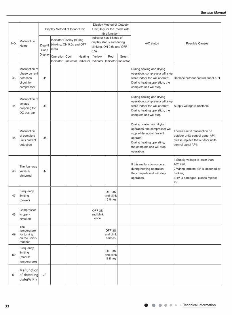
43
Malfunction of phase currentdetection circuit for compressor
U1
During cooling and dryingoperation, compressor will stopwhile indoor fan will operate;During heating operation, thecomplete unit will stop
Replace outdoor control panel AP1
44
Malfunction of voltagedropping forDC bus-bar
U3
During cooling and dryingoperation, compressor will stopwhile indoor fan will operate;During heating operation, thecomplete unit will stop
Supply voltage is unstable
45
Malfunction of complete units current detection
U5
During cooling and dryingoperation, the compressor willstop while indoor fan will operate; During heating operating, the complete unit will stop operation.
Theres circuit malfunction on outdoor units control panel AP1, please replace the outdoor units control panel AP1.
46
The four-wayvalve isabnormal
U7
If this malfunction occurs during heating operation, the complete unit will stop operation.
1.Supply voltage is lower than AC175V;2.Wiring terminal 4V is loosened or broken;3.4V is damaged, please replace 4V.
47
Frequency limiting (power)
OFF 3Sand blink13 times
48
Compressor is open-circuited
OFF 3Sand blink
once
49
The temperature for turning on the unit is reached
OFF 3Sand blink8 times
50
Frequency limiting (module temperature)
OFF 3Sand blink11 times
51
Malfunction of detecting plate(WIFI)
JF
33 Technical Information
Service Manual
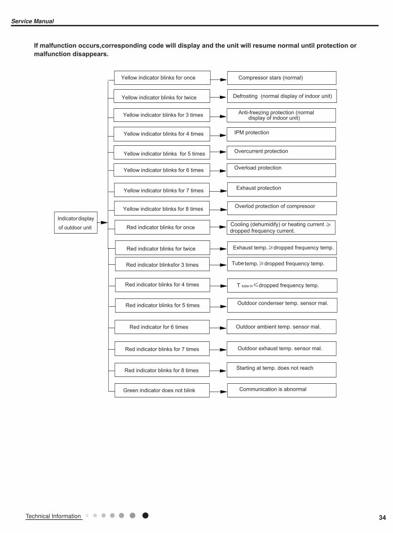
If malfunction occurs,corresponding code will display and the unit will resume normal until protection or
malfunction disappears.
34Technical Information
Service Manual
Analysis or processing of some of the malfunction display:
1. Compressor discharge protection
Possible causes: shortage of refrigerant; blockage of air filter; poor ventilation or air flow short pass for condenser; the system has noncondensing gas (such as air, water etc.); blockage of capillary assy (including filter); leakage inside four-way valve causes incorrect operation; malfunction of compressor; malfunction of protection relay; malfunction of discharge sensor; outdoor temperature too high. Processing method: refer to the malfunction analysis in the above section.2. Low voltage overcurrent protection
Possible cause: Sudden drop of supply voltage.3.
Processing method: Check if communication signal cable is connected reliably.4. Sensor open or short circuit
Processing method: Check whether sensor is normal, connected with the corre sponding position on the controller and if damage of lead wire is found.5. Compressor over load protection
Possible causes: insufficient or too much refrigrant; blockage of capillary and increase of suction temp.; improper running of compressor, burning in or stuck of bearing, damage of discharge valve; malfunction of protector.Processing method: adjust refrigerant amount; replace the capillary; replace the compressor; use universal meter to check if the contactor of compress or is fine when it is not overheated, if not replace the protector.6. System malfunction
i.e.overload protection.When tube temperature(Check the temperature of outdoor heat exchanger when cooling and check the temperatur e of indoor heat exchanger when heating) is too high, protection will be activated.Possible causes: Outdoor temperature is too high when cooling; insufficient outdoor air circulation; refrigerant flow malfunction.please refer to the malfunction analysis in the previous section for handling method .7. IPM module protection
Processing method:Once the module malfunction happens,if it persists for a long time and can not be selfcanceled, cut off the power and turn off the unit,and then re-energize the unit again after about 10 min.After repeating the procedure for sever times, if the malfunction still exists,replace the module.
35 Technical Information
Service Manual
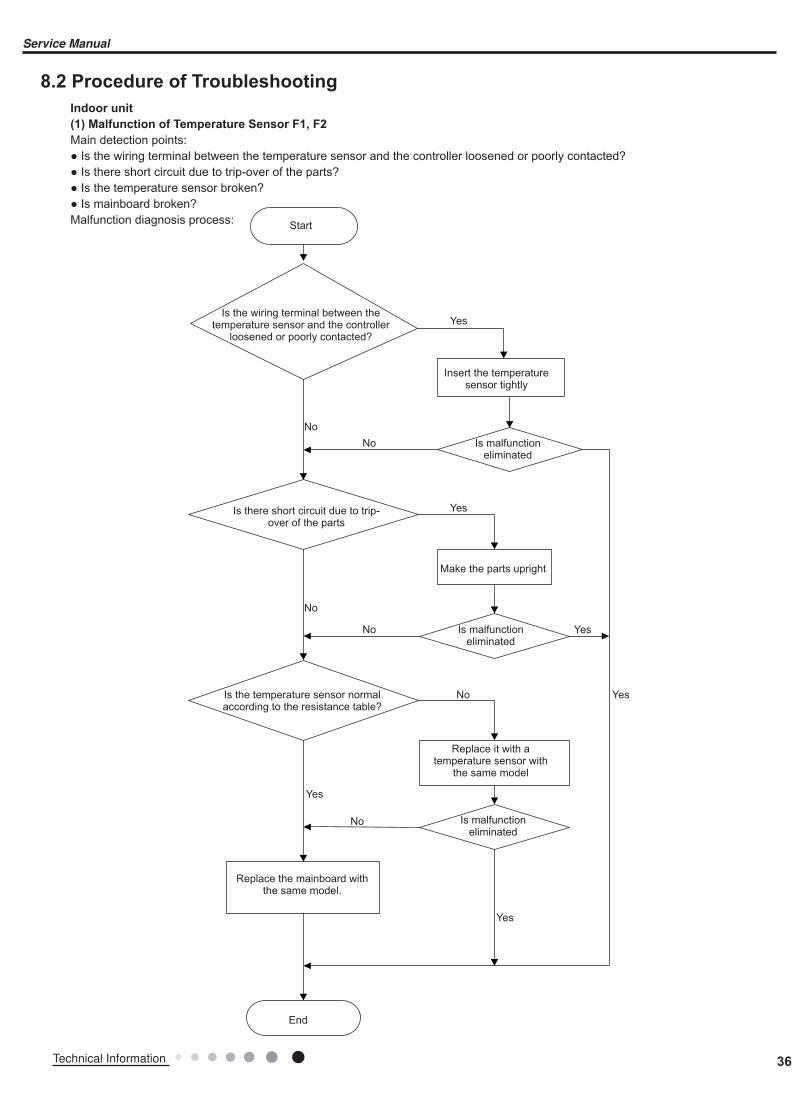
8.2 Procedure of Troubleshooting
Indoor unit
(1) Malfunction of Temperature Sensor F1, F2
Main detection points:● Is the wiring terminal between the temperature sensor and the controller loosened or poorly contacted?● Is there short circuit due to trip-over of the parts?● Is the temperature sensor broken?● Is mainboard broken?Malfunction diagnosis process:
Is the wiring terminal between the temperature sensor and the controller
loosened or poorly contacted?
Start
Insert the temperature sensor tightly
Yes
Yes
Yes
Yes
Yes
Yes
No
No
No
No
No
No
Is malfunction eliminated
Is malfunction eliminated
Is malfunction eliminated
Replace it with a temperature sensor with
the same model
Make the parts upright
Is there short circuit due to trip-over of the parts
Is the temperature sensor normal according to the resistance table?
Replace the mainboard with the same model.
End
36Technical Information
Service Manual
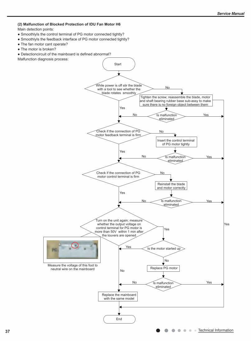
(2) Malfunction of Blocked Protection of IDU Fan Motor H6
Main detection points:● SmoothlyIs the control terminal of PG motor connected tightly?● SmoothlyIs the feedback interface of PG motor connected tightly?● The fan motor cant operate?● The motor is broken?● Detectioncircuit of the mainboard is defined abnormal?Malfunction diagnosis process:
Start
While power is off stir the blade with a tool to see whether the
blade rotates smoothly
Check if the connection of PG motor feedback terminal is firm
Check if the connection of PG motor control terminal is firm
Turn on the unit again; measure whether the output voltage on
control terminal for PG motor is more than 50V within 1 min after
the louvers are opened
Tighten the screw; reassemble the blade, motor and shaft bearing rubber base sub-assy to make
sure there is no foreign object between themYes
Yes
Yes
Yes
Yes
Yes
Yes
Yes
Yes
Yes
No
No
No
No
No
No
No
No
No
Is malfunction eliminated
Is malfunction eliminated
Is malfunction eliminated
Is malfunction eliminated
Is the motor started up
Replace PG motor
Replace the mainboard with the same model
Measure the voltage of this foot to neutral wire on the mainboard
End
Reinstall the blade and motor correctly
Insert the control terminal of PG motor tightly
37 Technical Information
Service Manual

(3) Malfunction of Protection of Jumper Cap C5
Main detection points:● Is there jumper cap on the mainboard?● Is the jumper cap inserted correctly and tightly?● The jumper is broken?● The motor is broken?● Detection circuit of the mainboard is defined abnormal?Malfunction diagnosis process:
Start
Is there jumper cap on the mainboard?
Is the jumper cap inserted correctly and tightly?
Replace the jumper cap with the same model
Appearance of the jumper cap
Assemble the jumpercap with the same model
Insert the jumper cap tightly
Is malfunction eliminated
Is malfunction eliminated
Is malfunction eliminated
Replace the mainboardwith the same model
End
Yes
Yes
Yes
Yes
Yes
No
No
No
No
No
38Technical Information
Service Manual
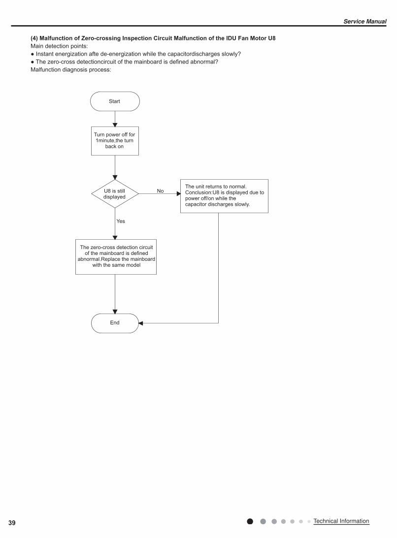
(4) Malfunction of Zero-crossing Inspection Circuit Malfunction of the IDU Fan Motor U8
Main detection points:● Instant energization afte de-energization while the capacitordischarges slowly?● The zero-cross detectioncircuit of the mainboard is defined abnormal?Malfunction diagnosis process:
Turn power off for 1minute,the turn
back on
The unit returns to normal. Conclusion:U8 is displayed due to power off/on while thecapacitor discharges slowly.
U8 is still displayed
The zero-cross detection circuit of the mainboard is defined
abnormal.Replace the mainboard with the same model
Yes
No
Start
End
39 Technical Information
Service Manual
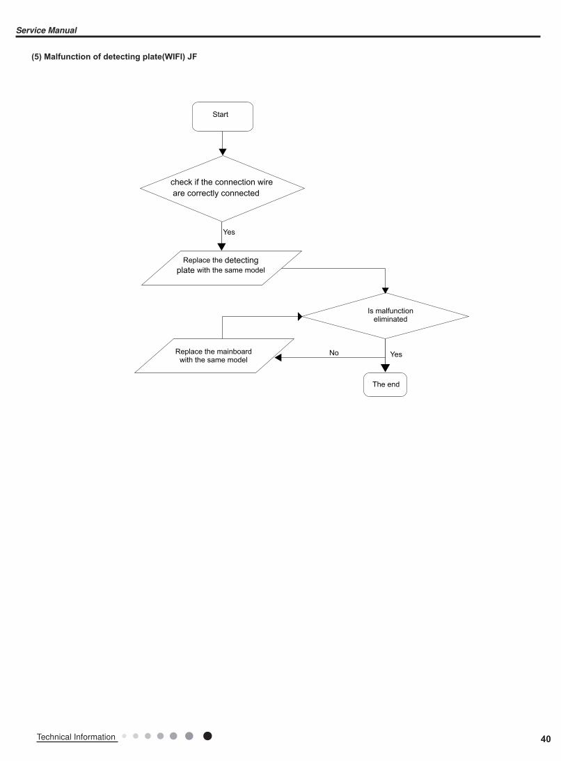
(5) Malfunction of detecting plate(WIFI) JF
Start
Is malfunction eliminated
The end
check if the connection wire
are correctly connected
Replace the detecting
plate with the same model
Replace the mainboard with the same model
Yes
Yes
No
40Technical Information
Service Manual
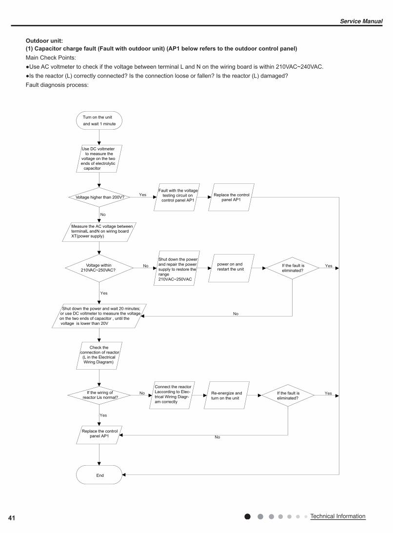
Outdoor unit:
(1) Capacitor charge fault (Fault with outdoor unit) (AP1 below refers to the outdoor control panel)
Main Check Points:●Use AC voltmeter to check if the voltage between terminal L and N on the wiring board is within 210VAC~240VAC.●Is the reactor (L) correctly connected? Is the connection loose or fallen? Is the reactor (L) damaged?Fault diagnosis process:
No
Yes
No
Yes
No
Yes
No
Yes
No
Yes
Turn on the unit
and wait 1 minute
Use DC voltmeter to measure the
voltage on the two ends of electrolytic
capacitor
Voltage higher than 200V?
Fault with the voltage testing circuit on
control panel AP1
Replace the control panel AP1
Measure the AC voltage between terminal L and N on wiring board XT(power supply)
Voltage within 210VAC~250VAC?
Shut down the power
and repair the power
supply to restore the
range
210VAC~250VAC
power on and
restart the unitIf the fault is
eliminated?
Shut down the power and wait 20 minutes; or use DC voltmeter to measure the voltage
on the two ends of capacitor , until the
voltage is lower than 20V
Check the connection of reactor (L in the Electrical Wiring Diagram)
If the wiring of reactor Lis normal?
Connect the reactor
Laccording to Elec-
trical Wiring Diagr-
am correctly
Re-energize and
turn on the unit
If the fault is
eliminated?
End
Replace the control panel AP1
41 Technical Information
Service Manual

(2) IPM Protection, Out-of-step Fault, Compressor Phase Overcurrent (AP1 below refers to the outdoor control panel)
Main check points:●Is the connection between control panel AP1 and compressor COMP secure? Loose? Is the connection in correct order?●Is the voltage input of the machine within normal range? (Use AC voltmeter to measure the voltage between terminal L and N on the wiring board XT)●Is the compressor coil resistance normal? Is the insulation of compressor coil against the copper tube in good condition?●Is the working load of the machine too high? Is the radiation good?●Is the charge volume of refrigerant correct?Fault diagnosis process:
42Technical Information
Service Manual

Energize and switch on
IPM protection occurs after the
machine has run for a period of time?
Use AC voltmeter to measure the voltage between terminal L and N on the wiring board XT)
If the voltage between terminal L and N on wiring board XT is within 210VAC~250VAC?
Check the supply voltage and restore it to
210VAC~250VAC
Voltage between
the two ends of celectrolytic capacitor is
Restart the unit. Before protection occurs, use DC voltmeter to measure the voltage
between the two ends of electrolytic capacitor on control
panel AP1
If the unit can work
normally?
Please confirm: 1. If the indoor and outdoor heat exchangers are dirty? If they are obstructed by other
objects which affect the heat exchange of indoor and outdoor unit. 2. If the indoor and outdoor fans are working normally?
3. If the environment temperature is too high, resulting in that the system
pressure is too high and exceeds the
permissible range? 4. If the charge volume of refrigerant is too much, resulting in that the system pressure is too high?
5. Other conditions resulting in that the system pressure becomes too high.
The connection of capacitor C2
is loose.
Reconnect the capacitor C2 according to Electrical Wiring Diagram. Then, Restart theunit.
Stop the unit and disconnect the power supply. Wait 20 minutes, or use DC voltmeter to measure the voltage
between the two ends of capacitor C2, until the
voltage is lower than 20V
Replace the capacitor C2. Then, energize and start the unit.
Replace the control panel AP1
Take corrective actions according to Technical Service Manual, and
then energize and start the unit.
If there is any abnormality
described above?
Replace the control panel AP1
If the connection between AP1 and COMP is unsecure or the connection order is wrong?
Connect the control panel AP1 and compressor COMP correctly according to the Electrical Wiring Diagram. Then, energize and start the unit.
Use ohmmeter to measure the resistance between the three terminals on compressor COMP, and compare the measurements with the
compressor resistance on Service Manual.
If the resistance is
normal?
Use ohmmeter to measure the resistance between the two
terminals of compressor COMP and copper tube.
Replace the compressor
COMP
Resistance higher than 500MΩ?
Replace the control panel
AP1
END
Yes No
YesNo
Yes
No
Yes
If the unit can work normallv?
Yes
Yes
Yes
If the unit can work normally?
No
No
Yes
No
If the unit can work normally?
Yes
No No
If the unit can work
normally?
Yes
Yes
No
Yes
No
No
Yes
higher than
250V
Remove the wires on the two ends ofcapacitor C2. Then,use capacitancemeter to measurethe capacitor C2.Verify as per theParameters Sheet.
Stop the unit and disconnect the power supply. Then, check the connection ofcapacitor C2according to ElectricalWiring Diagram.
If capacitorC2 is failed?
Refer to the Electrical Wiring Diagram and check if the connectionbetween AP1 andCOMP is loose and ifthe connection orderis correct.
43 Technical Information
Service Manual

(3) High temperature and overload protection diagnosis (AP1 hereinafter refers to the control board of the outdoor unit)
Mainly detect:●Is outdoor ambient temperature in normal range?●Are the outdoor and indoor fans operating normally?●Is the heat dissipation environment inside and outside the unit good?Fault diagnosis process:
End
Yes
No
Yes
No
Yes
No
Overheat and high
temperature protection
Is outdoor ambient temperature higher than 53?
20 minutes after the complete
unit is powered off.
Is heat dissipation of the indoor unit
and outdoor unit abnormal?
Normal protection, please operate
it after the outdoor ambient temp-
erature is normalized.
Improve the heat
dissipation environ-
ment of the unit
Does the outdoor fan work normally?
1. Check if the fan terminal OFAN
is connected correctly
2. Resistance between any two
terminals is measure by an ohm
gauge and should be less than 1K
Ohm.
Replace the
control panel AP1
Replace the fan
capacitor C1
Replace the
outdoor fan
44Technical Information
Service Manual

(4) Start-up failure (following AP1 for outdoor unit control board)
Mainly detect:●Whether the compressor wiring is connected correct?●Is compressor broken?●Is time for compressor stopping enough?Fault diagnosis process:
No
Yes
No
No
Yes
Yes
Yes
No
Power on the unit
Is stop time of the compressor
longer than 3 minutes?
Restart it up after
3 minutes
Does startup fail?
Are the wires for the compressor connected
correctly? Is connection sequence right?
Connect the wires as
per the connection
diagram
Replace the control panel AP1
If the fault is eliminated?
Replace the
compressor
End
45 Technical Information
Service Manual
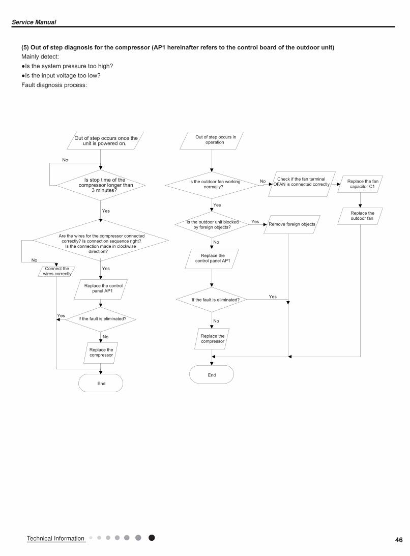
(5) Out of step diagnosis for the compressor (AP1 hereinafter refers to the control board of the outdoor unit)
Mainly detect:●Is the system pressure too high?●Is the input voltage too low?Fault diagnosis process:
Out of step occurs once the unit is powered on.
Is stop time of the compressor longer than
3 minutes?
Are the wires for the compressor connected correctly? Is connection sequence right?
Is the connection made in clockwise direction?
Connect the wires correctly
Replace the control panel AP1
If the fault is eliminated?
Replace the compressor
End
Out of step occurs in operation
Is the outdoor fan working normally?
Is the outdoor unit blocked by foreign objects?
Replace the control panel AP1
If the fault is eliminated?
Replace the compressor
End
Check if the fan terminal OFAN is connected correctly
Remove foreign objects
Replace the fan capacitor C1
Replace the outdoor fan
No
No
No
No
No
No
Yes
Yes
Yes
Yes
Yes
Yes
46Technical Information
Service Manual
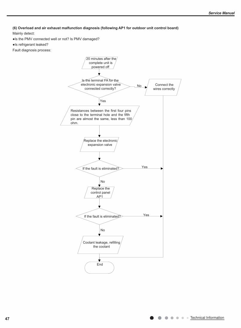
(6) Overload and air exhaust malfunction diagnosis (following AP1 for outdoor unit control board)
Mainly detect:●Is the PMV connected well or not? Is PMV damaged?●Is refrigerant leaked?Fault diagnosis process:
20 minutes after the
complete unit is
powered off
Is the terminal FA for the
electronic expansion valve
connected correctly?Connect the
wires correctly
Resistances between the first four pins
close to the terminal hole and the fifth
pin are almost the same, less than 100
ohm.
Replace the electronic
expansion valve
If the fault is eliminated?
If the fault is eliminated?
Replace the
control panel
AP1
Coolant leakage, refilling
the coolant
End
No
No
No
Yes
Yes
Yes
47 Technical Information
Service Manual
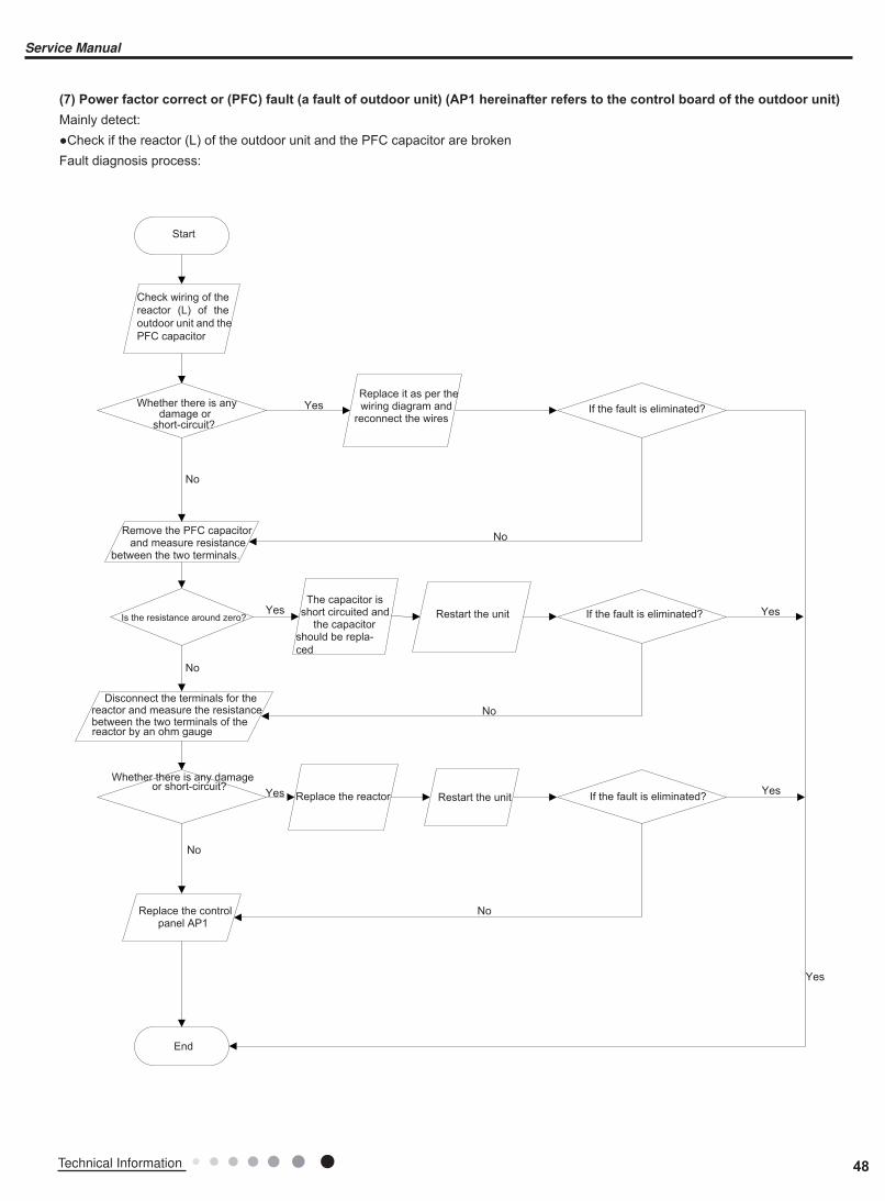
(7) Power factor correct or (PFC) fault (a fault of outdoor unit) (AP1 hereinafter refers to the control board of the outdoor unit)
Mainly detect:●Check if the reactor (L) of the outdoor unit and the PFC capacitor are brokenFault diagnosis process:
Yes
Yes
No
No
No
No
No
No
Yes
Yes
Yes
Start
Check wiring of the
reactor (L) of the
outdoor unit and the
PFC capacitor
Whether there is any damage or
short-circuit?
Replace it as per the wiring diagram and
reconnect the wiresIf the fault is eliminated?
Remove the PFC capacitor and measure resistance
between the two terminals.
Is the resistance around zero?
The capacitor is short circuited and
the capacitor should be repla-
ced
Restart the unit If the fault is eliminated?
Disconnect the terminals for the reactor and measure the resistance between the two terminals of the reactor by an ohm gauge
Whether there is any damage or short-circuit?
Replace the reactor Restart the unit If the fault is eliminated?
Replace the control panel AP1
End
Yes
48Technical Information
Service Manual
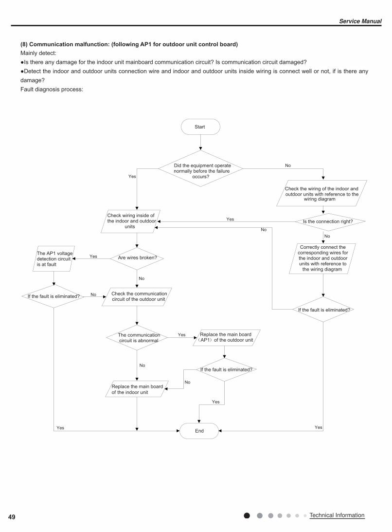
(8) Communication malfunction: (following AP1 for outdoor unit control board)
Mainly detect:●Is there any damage for the indoor unit mainboard communication circuit? Is communication circuit damaged?●Detect the indoor and outdoor units connection wire and indoor and outdoor units inside wiring is connect well or not, if is there any damage?Fault diagnosis process:
Yes
No
Yes
No
No
Yes
No
No
Yes
No
Yes
No
Yes
Yes
Start
Did the equipment operate normally before the failure
occurs?
The AP1 voltage detection circuit is at fault
Check wiring inside of the indoor and outdoor
units
Are wires broken?
Check the communication circuit of the outdoor unit
If the fault is eliminated?
The communication circuit is abnormal
Replace the main board
of the indoor unit
End
If the fault is eliminated?
Replace the main board AP1 of the outdoor unit
If the fault is eliminated?
Is the connection right?
Check the wiring of the indoor and outdoor units with reference to the
wiring diagram
Correctly connect the corresponding wires for the indoor and outdoor units with reference to
the wiring diagram
49 Technical Information
Service Manual
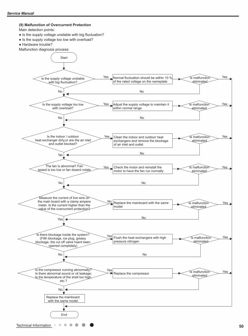
(9) Malfunction of Overcurrent Protection
Main detection points:● Is the supply voltage unstable with big fluctuation?● Is the supply voltage too low with overload?● Hardware trouble?Malfunction diagnosis process:
Start
Is the supply voltage unstablewith big fluctuation?
Normal fluctuation should be within 10 % of the rated voltage on the nameplate
Adjust the supply voltage to maintain it within normal range
Clean the indoor and outdoor heat exchangers and remove the blockage of air inlet and outlet
Check the motor and reinstall the motor to have the fan run normally
Replace the mainboard with the same model
Flush the heat exchangers with high pressure nitrogen
Replace the compressor
Replace the mainboard with the same model
End
Is the supply voltage too lowwith overload?
Is the indoor / outdoorheat exchanger dirty,or are the air inlet
and outlet blocked?
The fan is abnormal? Fanspeed is too low or fan doesnt rotate
Measure the current of live wire on the main board with a clamp ampere meter. Is the current higher than the value of the overcurrent protection?
Is there blockage inside the system? (Filth blockage, ice plug, greasy
blockage, the cut off valve hasnt been opened completely)
Is the compressor running abnormally? Is there abnormal sound or oil leakage; Is the temperature of the shell too high,
etc.?
Is malfunction eliminated
Is malfunction eliminated
Is malfunction eliminated
Is malfunction eliminated
Is malfunction eliminated
Is malfunction eliminated
Is malfunction eliminated
Yes Yes
Yes
Yes
Yes
Yes
Yes
Yes
Yes
Yes
Yes
Yes
Yes
Yes
No No
No
No
No
No
No No
No
No
No
No
No
50Technical Information
Service Manual
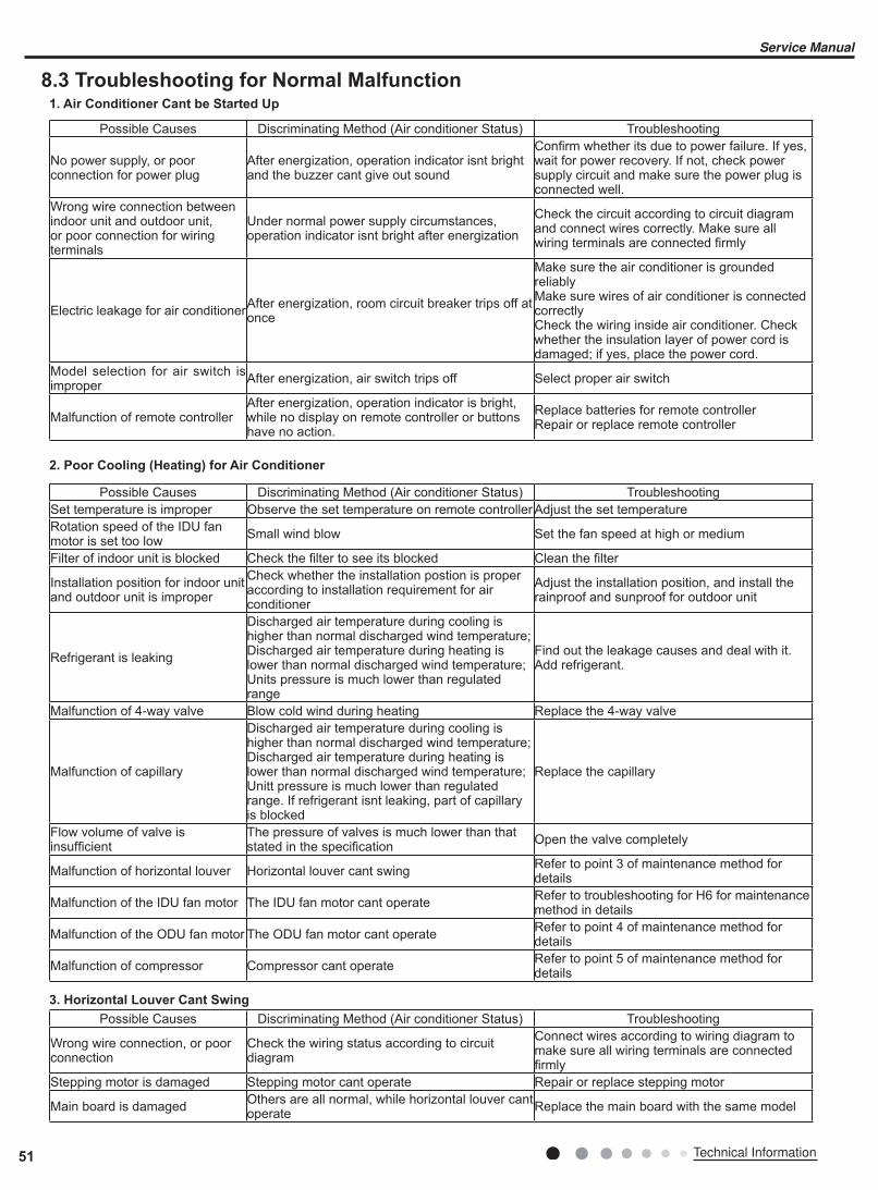
Possible Causes Discriminating Method (Air conditioner Status) Troubleshooting Set temperature is improper Observe the set temperature on remote controller Adjust the set temperatureRotation speed of the IDU fan motor is set too low Small wind blow Set the fan speed at high or medium
Filter of indoor unit is blocked Check the filter to see its blocked Clean the filter
Installation position for indoor unit and outdoor unit is improper
Check whether the installation postion is proper according to installation requirement for air conditioner
Adjust the installation position, and install the rainproof and sunproof for outdoor unit
Refrigerant is leaking
Discharged air temperature during cooling is higher than normal discharged wind temperature; Discharged air temperature during heating is lower than normal discharged wind temperature; Units pressure is much lower than regulated range
Find out the leakage causes and deal with it. Add refrigerant.
Malfunction of 4-way valve Blow cold wind during heating Replace the 4-way valve
Malfunction of capillary
Discharged air temperature during cooling is higher than normal discharged wind temperature; Discharged air temperature during heating is lower than normal discharged wind temperature; Unitt pressure is much lower than regulated range. If refrigerant isnt leaking, part of capillary is blocked
Replace the capillary
Flow volume of valve is insufficient
The pressure of valves is much lower than that stated in the specification Open the valve completely
Malfunction of horizontal louver Horizontal louver cant swing Refer to point 3 of maintenance method for details
Malfunction of the IDU fan motor The IDU fan motor cant operate Refer to troubleshooting for H6 for maintenance method in details
Malfunction of the ODU fan motor The ODU fan motor cant operate Refer to point 4 of maintenance method for details
Malfunction of compressor Compressor cant operate Refer to point 5 of maintenance method for details
8.3 Troubleshooting for Normal Malfunction1. Air Conditioner Cant be Started Up
2. Poor Cooling (Heating) for Air Conditioner
3. Horizontal Louver Cant Swing
Possible Causes Discriminating Method (Air conditioner Status) Troubleshooting
No power supply, or poor connection for power plug
After energization, operation indicator isnt bright and the buzzer cant give out sound
Confirm whether its due to power failure. If yes, wait for power recovery. If not, check power supply circuit and make sure the power plug is connected well.
Wrong wire connection between indoor unit and outdoor unit, or poor connection for wiring terminals
Under normal power supply circumstances, operation indicator isnt bright after energization
Check the circuit according to circuit diagram and connect wires correctly. Make sure all wiring terminals are connected firmly
Electric leakage for air conditionerAfter energization, room circuit breaker trips off at once
Make sure the air conditioner is grounded reliablyMake sure wires of air conditioner is connected correctlyCheck the wiring inside air conditioner. Check whether the insulation layer of power cord is damaged; if yes, place the power cord.
Model selection for air switch is improper After energization, air switch trips off Select proper air switch
Malfunction of remote controller After energization, operation indicator is bright, while no display on remote controller or buttons have no action.
Replace batteries for remote controllerRepair or replace remote controller
Possible Causes Discriminating Method (Air conditioner Status) Troubleshooting
Wrong wire connection, or poor connection
Check the wiring status according to circuit diagram
Connect wires according to wiring diagram to make sure all wiring terminals are connected firmly
Stepping motor is damaged Stepping motor cant operate Repair or replace stepping motor
Main board is damaged Others are all normal, while horizontal louver cant operate Replace the main board with the same model
51 Technical Information
Service Manual
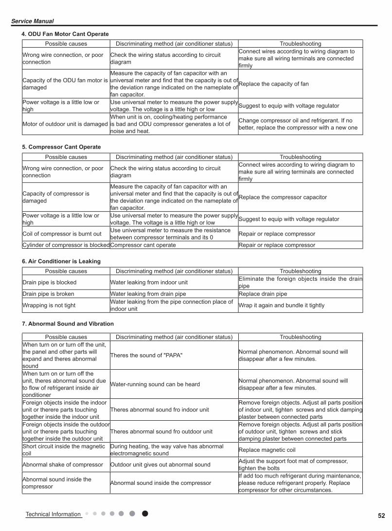
7. Abnormal Sound and Vibration
Possible causes Discriminating method (air conditioner status) Troubleshooting When turn on or turn off the unit, the panel and other parts will expand and theres abnormal sound
Theres the sound of "PAPA" Normal phenomenon. Abnormal sound will disappear after a few minutes.
When turn on or turn off the unit, theres abnormal sound due to flow of refrigerant inside air conditioner
Water-running sound can be heard Normal phenomenon. Abnormal sound will disappear after a few minutes.
Foreign objects inside the indoor unit or therere parts touching together inside the indoor unit
Theres abnormal sound fro indoor unitRemove foreign objects. Adjust all parts position of indoor unit, tighten screws and stick damping plaster between connected parts
Foreign objects inside the outdoor unit or therere parts touching together inside the outdoor unit
Theres abnormal sound fro outdoor unitRemove foreign objects. Adjust all parts position of outdoor unit, tighten screws and stick damping plaster between connected parts
Short circuit inside the magnetic coil
During heating, the way valve has abnormal electromagnetic sound Replace magnetic coil
Abnormal shake of compressor Outdoor unit gives out abnormal sound Adjust the support foot mat of compressor, tighten the bolts
Abnormal sound inside the compressor Abnormal sound inside the compressor
If add too much refrigerant during maintenance, please reduce refrigerant properly. Replace compressor for other circumstances.
6. Air Conditioner is Leaking
Possible causes Discriminating method (air conditioner status) Troubleshooting
Drain pipe is blocked Water leaking from indoor unit Eliminate the foreign objects inside the drain pipe
Drain pipe is broken Water leaking from drain pipe Replace drain pipe
Wrapping is not tight Water leaking from the pipe connection place of indoor unit Wrap it again and bundle it tightly
5. Compressor Cant Operate
Possible causes Discriminating method (air conditioner status) Troubleshooting
Wrong wire connection, or poor connection
Check the wiring status according to circuit diagram
Connect wires according to wiring diagram to make sure all wiring terminals are connected firmly
Capacity of compressor is damaged
Measure the capacity of fan capacitor with an universal meter and find that the capacity is out of the deviation range indicated on the nameplate of fan capacitor.
Replace the compressor capacitor
Power voltage is a little low or high
Use universal meter to measure the power supply voltage. The voltage is a little high or low Suggest to equip with voltage regulator
Coil of compressor is burnt out Use universal meter to measure the resistance between compressor terminals and its 0 Repair or replace compressor
Cylinder of compressor is blocked Compressor cant operate Repair or replace compressor
4. ODU Fan Motor Cant Operate
Possible causes Discriminating method (air conditioner status) Troubleshooting
Wrong wire connection, or poor connection
Check the wiring status according to circuit diagram
Connect wires according to wiring diagram to make sure all wiring terminals are connected firmly
Capacity of the ODU fan motor is damaged
Measure the capacity of fan capacitor with an universal meter and find that the capacity is out of the deviation range indicated on the nameplate of fan capacitor.
Replace the capacity of fan
Power voltage is a little low or high
Use universal meter to measure the power supply voltage. The voltage is a little high or low Suggest to equip with voltage regulator
Motor of outdoor unit is damagedWhen unit is on, cooling/heating performance is bad and ODU compressor generates a lot of noise and heat.
Change compressor oil and refrigerant. If no better, replace the compressor with a new one
52Technical Information
Service Manual

9. Exploded View and Parts List
9.1 Indoor Unit
The component picture is only for reference; please refer to the actual product.
09K/12K
53 Technical Information
Service Manual
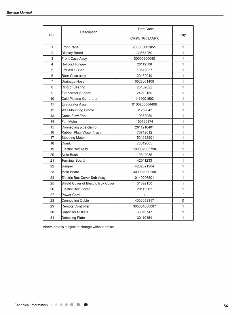
Above data is subject to change without notice.
NO.Description
Part Code
QtyC����09Aar�
1 Front Panel 20000300105S 1
2 Display Board 30565260 1
3 Front Case Assy 00000200040 1
4 Helicoid Tongue 26112508 1
5 Left Axile Bush 10512037 1
6 Rear Case assy 20162010 1
7 Drainage Hose 0523001408 1
8 Ring of Bearing 26152022 1
9 Evaporator Support 24212180 1
10 Cold Plasma Generator 1114001603 1
11 Evaporator Assy 0100200004406 1
12 Wall Mounting Frame 01252043 1
13 Cross Flow Fan 10352059 1
14 Fan Motor 150120874 1
15 Connecting pipe clamp 2611216401 1
16 Rubber Plug (Water Tray) 76712012 1
17 Stepping Motor 1521212901 1
18 Crank 73012005 1
19 Electric Box Assy 100002003790 1
20 Axile Bush 10542036 1
21 Terminal Board 42011233 1
22 Jumper 4202021904 1
23 Main Board 300002000288 1
24 Electric Box Cover Sub-Assy 0140206501 1
25 Shield Cover of Electric Box Cover 01592150 1
26 Electric Box Cover 20112207 1
27 Power Cord / /28 Connecting Cable 4002052317 0
29 Remote Controller 305001000087 1
30 Capacitor CBB61 33010747 1
31 Detecting Plate 30110154 1
54Technical Information
Service Manual

Above data is subject to change without notice.
NO.Description
Part Code
QtyC� ����12Aar�
1 Front Panel 20000300105S 1
2 Display Board 30565260 1
3 Front Case Assy 00000200040 1
4 Helicoid Tongue 26112508 1
5 Left Axile Bush 10512037 1
6 Rear Case assy 20162010 1
7 Drainage Hose 0523001408 1
8 Ring of Bearing 26152022 1
9 Evaporator Support 24212180 1
10 Cold Plasma Generator 1114001603 1
11 Evaporator Assy 0110010009507 1
12 Wall Mounting Frame 01252043 1
13 Cross Flow Fan 10352059 1
14 Fan Motor 150120874 1
15 Connecting pipe clamp 2611216401 1
16 Rubber Plug (Water Tray) 76712012 1
17 Stepping Motor 1521212901 1
18 Crank 73012005 1
19 Electric Box Assy 100002002895 1
20 Axile Bush 10542036 1
21 Terminal Board 42011233 1
22 Jumper 4202021911 1
23 Main Board 30145096 1
24 Electric Box Cover Sub-Assy 0140206501 1
25 Shield Cover of Electric Box Cover 01592150 1
26 Electric Box Cover 20112207 1
27 Power Cord / /28 Connecting Cable 4002052317 0
29 Remote Controller 305001000087 1
30 Capacitor CBB61 33010747 1
31 Detecting Plate 30110154 1
55 Technical Information
Service Manual
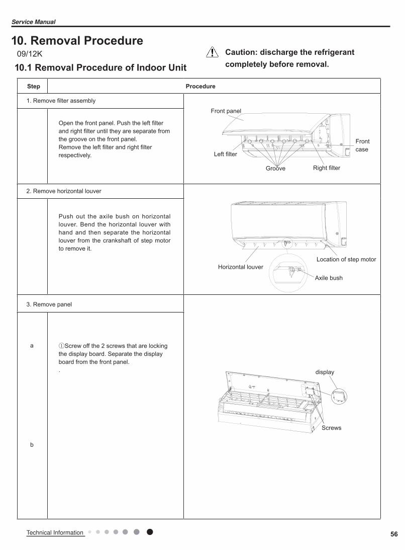
10. Removal Procedure
10.1 Removal Procedure of Indoor Unit
Caution: discharge the refrigerant
completely before removal.
a
b
Axile bush
Push out the axile bush on horizontal louver. Bend the horizontal louver with hand and then separate the horizontal louver from the crankshaft of step motor to remove it.
Horizontal louverLocation of step motor
ProcedureStep
1. Remove filter assembly
2. Remove horizontal louver
Front panel
Frontcase
Right filterGroove
Left filter
Open the front panel. Push the left filter and right filter until they are separate from the groove on the front panel.Remove the left filter and right filter respectively.
①Screw off the 2 screws that are locking the display board. Separate the display board from the front panel..
3. Remove panel
Screws
display
09/12K
56Technical Information
Service Manual
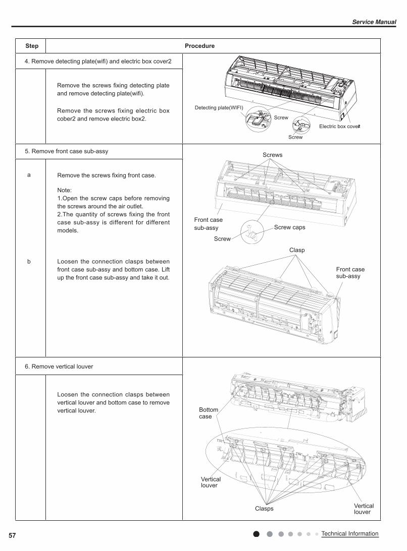
a
b
ProcedureStep
Remove the screws fixing front case.
Note:1.Open the screw caps before removing the screws around the air outlet.2.The quantity of screws fixing the front case sub-assy is different for different models.
Loosen the connection clasps between vertical louver and bottom case to remove vertical louver.
Loosen the connection clasps between front case sub-assy and bottom case. Lift up the front case sub-assy and take it out.
5. Remove front case sub-assy
6. Remove vertical louver
Front case sub-assy
Front case sub-assy
Clasp
Screw caps
Screws
Screw
Vertical louver
Vertical louver
Clasps
Bottom case
Remove the screws fixing detecting plate and remove detecting plate(wifi).
Remove the screws fixing electric box cober2 and remove electric box2.
4. Remove detecting plate(wifi) and electric box cover2
Detecting plate(WIFI)
2
57 Technical Information
Service Manual

a
b
c
ProcedureStep
Loosen the connection clasps between shield cover of electric box sub-assy and electric box, and then remove the shield cover of electric box sub-assy.Remove the screw fixing electric box assy .
① Take off the water retaining sheet. Remove the cold plasma generator by screwing off the locking screw on the generator.② Take off the indoor tube temperature sensor.③ Screw off 1 grounding screw.④ Remove the wiring terminals of motor and stepping motor.⑤ Remove the electric box assy.
Twist off the screws that are lockingeach lead wire and rotate the electricbox assy.Twist off the screws that are locking thewire clip. Loosen the power cord andremove its wiring terminal. Lift up themain board and take it off.
7. Remove electric box assy
Electric box
Electric box assy
Clasps
Shield cover of electric box sub-assy
Cold plasmagenerator
Water retainingsheet
Grounding screw
Screw
Power cord
Wire clip
Screw
Main board
Screw
Indoor tubetemperature sensor
Wiringterminalof motor
Wiringterminalof steppingmotor
Screw
58Technical Information
Service Manual
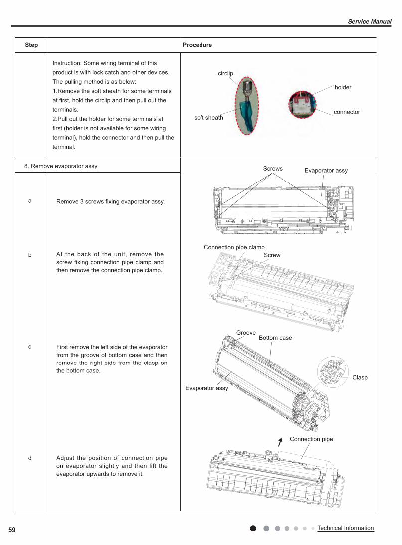
a
c
d
b
First remove the left side of the evaporator from the groove of bottom case and then remove the right side from the clasp on the bottom case.
Instruction: Some wiring terminal of this product is with lock catch and other devices. The pulling method is as below: 1.Remove the soft sheath for some terminals at first, hold the circlip and then pull out the terminals. 2.Pull out the holder for some terminals at first (holder is not available for some wiring terminal), hold the connector and then pull the terminal.
circlip
soft sheath
holder
connector
ProcedureStep
Remove 3 screws fixing evaporator assy.
8. Remove evaporator assy Screws
Connection pipe clamp
Evaporator assy
Evaporator assy
Screw
GrooveBottom case
Clasp
Connection pipe
At the back of the unit, remove the screw fixing connection pipe clamp and then remove the connection pipe clamp.
Adjust the position of connection pipe on evaporator slightly and then lift the evaporator upwards to remove it.
59 Technical Information
Service Manual

ProcedureStep
Remove the screws fixing motor clamp and then remove the motor clamp.
Remove the screws at the connection place of cross flow blade and motor; lift the motor and cross flow blade upwards to remove them.Remove the bearing holder sub-assy.Remove the screw fixing step motor and then remove the step motor.
Screws
Screw
Motor clamp
9. Remove motor and cross flow blade
Motor
Cross flow
Holder sub-assy
Step motorScrews
a
b
60Technical Information
Service Manual

Appendix:
1.Standard length of connection pipe● 5m, 7.5m, 8m.2.Min length of connection pipeFor the unit with standard connection pipe of 5m, there is no limitation for themin length of connection pipe. For the unit with standard connection pipe of 7.5m and 8m, the min length of connection pipe is 3m.3.Max length of connection pipe(More details please refer to the specifications)4.The additional refrigerant oil and refrigerant charging required after prolonging connection pipe● After the length of connection pipe is prolonged for 10m at the basis of standard length, you should add 5ml of refrigerant oil for each additional 5m of connection pipe.● The calculation method of additional refrigerant charging amount (on the basis of liquid pipe):● Basing on the length of standard pipe, add refrigerant according to the requirement as shown in the table. The additional refrigerant charging amount per meter is different according to the diameter of liquid pipe. See Sheet 2.● Additional refrigerant charging amount = prolonged length of liquid pipe X additional refrigerant charging amount per meter
Appendix 1: Reference Sheet of Celsius and Fahrenheit
Appendix 2: Configuration of Connection Pipe
Set temperature
Conversion formula for Fahrenheit degree and Celsius degree: Tf=Tcx1.8+32
Ambient temperature
Fahrenheit display
temperature(℉)
Fahrenheit(℉)
Celsius(℃)
Fahrenheit display
temperature(℉)
Fahrenheit(℉)
Celsius(℃)
Fahrenheit display
temperature(℉)
Fahrenheit(℉)
Celsius(℃)
32/33 32 0 55/56 55.4 13 79/80 78.8 26
34/35 33.8 1 57/58 57.2 14 81 80.6 27
36 35.6 2 59/60 59 15 82/83 82.4 28
37/38 37.4 3 61/62 60.8 16 84/85 84.2 29
39/40 39.2 4 63 62.6 17 86/87 86 30
41/42 41 5 64/65 64.4 18 88/89 87.8 31
43/44 42.8 6 66/67 66.2 19 90 89.6 32
45 44.6 7 68/69 68 20 91/92 91.4 33
46/47 46.4 8 70/71 69.8 21 93/94 93.2 34
48/49 48.2 9 72 71.6 22 95/96 95 35
50/51 50 10 73/74 73.4 23 97/98 96.8 36
52/53 51.8 11 75/76 75.2 24 99 98.6 37
54 53.6 12 77/78 77 25
Fahrenheit display
temperature(℉)
Fahrenheit(℉)
Celsius(℃)
Fahrenheit display
temperature(℉)
Fahrenheit(℉)
Celsius(℃)
Fahrenheit display
temperature(℉)
Fahrenheit(℉)
Celsius(℃)
61 60.8 16 69/70 69.8 21 78/79 78.8 26
62/63 62.6 17 71/72 71.6 22 80/81 80.6 27
64/65 64.4 18 73/74 73.4 23 82/83 82.4 28
66/67 66.2 19 75/76 75.2 24 84/85 84.2 29
68 68 20 77 77 25 86 86 30
Additional refrigerant charging amount for R32Diameter of connection pipe Indoor unit throttl Outdoor unit throttle
Liquid pipe Gas pipe Cooling only,cooling and heating(g / m) Cooling only(g / m) Cooling and heating(g / m)
Ф6 Ф9.5 or Ф12 16 12 16
Ф6 or Ф9.5 Ф16 or Ф19 40 12 40
Ф12 Ф19 or Ф22.2 80 24 96
Ф16 Ф25.4 or Ф31.8 136 48 96
Ф19 / 200 200 200
Ф22.2 / 280 280 280
Note: The additional refrigerant charging amount in Sheet 2 is recommendedvalue, not compulsory.
61 Technical Information
Service Manual

F:Inspection● Check the quality of expanding port. If there is any blemish, expand the port again according to the steps above.
The length is equal
Improper expanding
leaning damagedsurface
crack uneventhickness
Smooth surface
Downwards
Pipe
Shaper
Union pipe
Pipe
Expander
Hardmold
Pipe
Pipe
Pipe cutter
Leaning Uneven Burr
Improper pipe expanding is the main cause of refrigerant leakage.Please
expand the pipe according to the following steps:
A:Cut the pip● Confirm the pipe length according to the distance of indoor unit and outdoor unit.● Cut the required pipe with pipe cutter.
B:Remove the burrs● Remove the burrs with shaper and prevent the burrs from getting into the pipe.
C:Put on suitable insulating pipe
D:Put on the union nut● Remove the union nut on the indoor connection pipe and outdoor valve; installthe union nut on the pipe.
E:Expand the port● Expand the port with expander.
● "A" is different according to the diameter, please refer to the sheet below:
Outer diameter(mm) A(mm)Max Min
Ф6 - 6.35 (1/4") 1.3 0.7
Ф9.52 (3/8") 1.6 1.0
Ф12 - 12.70 (1/2") 1.8 1.0
Ф16 - 15.88 (5/8") 2.4 2.2
Appendix 3: Pipe Expanding Method
Note:
Note:
62Technical Information
Service Manual

Appendix 4: List of Resistance for Temperature Sensor
Resistance Table of Ambient Temperature Sensor for Indoor and Outdoor (15K)
Temp(oC) Resistance(kΩ) Temp(oC) Resistance(kΩ) Temp(oC) Resistance(kΩ) Temp(oC) Resistance(kΩ)
-19 138.1 20 18.75 59 3.848 98 1.071
-18 128.6 21 17.93 60 3.711 99 1.039
-17 121.6 22 17.14 61 3.579 100 1.009
-16 115 23 16.39 62 3.454 101 0.98
-15 108.7 24 15.68 63 3.333 102 0.952
-14 102.9 25 15 64 3.217 103 0.925
-13 97.4 26 14.36 65 3.105 104 0.898
-12 92.22 27 13.74 66 2.998 105 0.873
-11 87.35 28 13.16 67 2.896 106 0.848
-10 82.75 29 12.6 68 2.797 107 0.825
-9 78.43 30 12.07 69 2.702 108 0.802
-8 74.35 31 11.57 70 2.611 109 0.779
-7 70.5 32 11.09 71 2.523 110 0.758
-6 66.88 33 10.63 72 2.439 111 0.737
-5 63.46 34 10.2 73 2.358 112 0.717
-4 60.23 35 9.779 74 2.28 113 0.697
-3 57.18 36 9.382 75 2.206 114 0.678
-2 54.31 37 9.003 76 2.133 115 0.66
-1 51.59 38 8.642 77 2.064 116 0.642
0 49.02 39 8.297 78 1.997 117 0.625
1 46.6 40 7.967 79 1.933 118 0.608
2 44.31 41 7.653 80 1.871 119 0.592
3 42.14 42 7.352 81 1.811 120 0.577
4 40.09 43 7.065 82 1.754 121 0.561
5 38.15 44 6.791 83 1.699 122 0.547
6 36.32 45 6.529 84 1.645 123 0.532
7 34.58 46 6.278 85 1.594 124 0.519
8 32.94 47 6.038 86 1.544 125 0.505
9 31.38 48 5.809 87 1.497 126 0.492
10 29.9 49 5.589 88 1.451 127 0.48
11 28.51 50 5.379 89 1.408 128 0.467
12 27.18 51 5.197 90 1.363 129 0.456
13 25.92 52 4.986 91 1.322 130 0.444
14 24.73 53 4.802 92 1.282 131 0.433
15 23.6 54 4.625 93 1.244 132 0.422
16 22.53 55 4.456 94 1.207 133 0.412
17 21.51 56 4.294 95 1.171 134 0.401
18 20.54 57 4.139 96 1.136 135 0.391
19 19.63 58 3.99 97 1.103 136 0.382
63 Technical Information
Service Manual
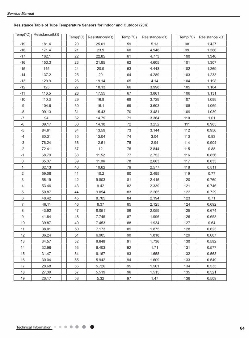
Resistance Table of Tube Temperature Sensors for Indoor and Outdoor (20K)
Temp(oC) Resistance(kΩ)Temp(oC) Resistance(kΩ) Temp(oC) Resistance(kΩ) Temp(oC) Resistance(kΩ)
-19 181.4 20 25.01 59 5.13 98 1.427
-18 171.4 21 23.9 60 4.948 99 1.386
-17 162.1 22 22.85 61 4.773 100 1.346
-16 153.3 23 21.85 62 4.605 101 1.307
-15 145 24 20.9 63 4.443 102 1.269
-14 137.2 25 20 64 4.289 103 1.233
-13 129.9 26 19.14 65 4.14 104 1.198
-12 123 27 18.13 66 3.998 105 1.164
-11 116.5 28 17.55 67 3.861 106 1.131
-10 110.3 29 16.8 68 3.729 107 1.099
-9 104.6 30 16.1 69 3.603 108 1.069
-8 99.13 31 15.43 70 3.481 109 1.039
-7 94 32 14.79 71 3.364 110 1.01
-6 89.17 33 14.18 72 3.252 111 0.983
-5 84.61 34 13.59 73 3.144 112 0.956
-4 80.31 35 13.04 74 3.04 113 0.93
-3 76.24 36 12.51 75 2.94 114 0.904
-2 72.41 37 12 76 2.844 115 0.88
-1 68.79 38 11.52 77 2.752 116 0.856
0 65.37 39 11.06 78 2.663 117 0.833
1 62.13 40 10.62 79 2.577 118 0.811
2 59.08 41 10.2 80 2.495 119 0.77
3 56.19 42 9.803 81 2.415 120 0.769
4 53.46 43 9.42 82 2.339 121 0.746
5 50.87 44 9.054 83 2.265 122 0.729
6 48.42 45 8.705 84 2.194 123 0.71
7 46.11 46 8.37 85 2.125 124 0.692
8 43.92 47 8.051 86 2.059 125 0.674
9 41.84 48 7.745 87 1.996 126 0.658
10 39.87 49 7.453 88 1.934 127 0.64
11 38.01 50 7.173 89 1.875 128 0.623
12 36.24 51 6.905 90 1.818 129 0.607
13 34.57 52 6.648 91 1.736 130 0.592
14 32.98 53 6.403 92 1.71 131 0.577
15 31.47 54 6.167 93 1.658 132 0.563
16 30.04 55 5.942 94 1.609 133 0.549
17 28.68 56 5.726 95 1.561 134 0.535
18 27.39 57 5.519 96 1.515 135 0.521
19 26.17 58 5.32 97 1.47 136 0.509
64Technical Information
Service Manual
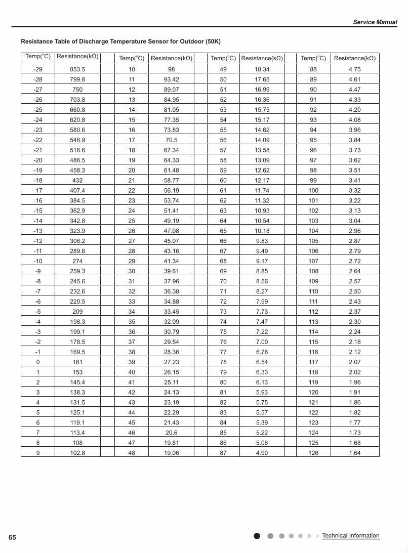
Resistance Table of Discharge Temperature Sensor for Outdoor (50K)
Temp(oC) Resistance(kΩ) Temp(oC) Resistance(kΩ) Temp(oC) Resistance(kΩ) Temp(oC) Resistance(kΩ)
-29 853.5 10 98 49 18.34 88 4.75
-28 799.8 11 93.42 50 17.65 89 4.61
-27 750 12 89.07 51 16.99 90 4.47
-26 703.8 13 84.95 52 16.36 91 4.33
-25 660.8 14 81.05 53 15.75 92 4.20
-24 620.8 15 77.35 54 15.17 93 4.08
-23 580.6 16 73.83 55 14.62 94 3.96
-22 548.9 17 70.5 56 14.09 95 3.84
-21 516.6 18 67.34 57 13.58 96 3.73
-20 486.5 19 64.33 58 13.09 97 3.62
-19 458.3 20 61.48 59 12.62 98 3.51
-18 432 21 58.77 60 12.17 99 3.41
-17 407.4 22 56.19 61 11.74 100 3.32
-16 384.5 23 53.74 62 11.32 101 3.22
-15 362.9 24 51.41 63 10.93 102 3.13
-14 342.8 25 49.19 64 10.54 103 3.04
-13 323.9 26 47.08 65 10.18 104 2.96
-12 306.2 27 45.07 66 9.83 105 2.87
-11 289.6 28 43.16 67 9.49 106 2.79
-10 274 29 41.34 68 9.17 107 2.72
-9 259.3 30 39.61 69 8.85 108 2.64
-8 245.6 31 37.96 70 8.56 109 2.57
-7 232.6 32 36.38 71 8.27 110 2.50
-6 220.5 33 34.88 72 7.99 111 2.43
-5 209 34 33.45 73 7.73 112 2.37
-4 198.3 35 32.09 74 7.47 113 2.30
-3 199.1 36 30.79 75 7.22 114 2.24
-2 178.5 37 29.54 76 7.00 115 2.18
-1 169.5 38 28.36 77 6.76 116 2.12
0 161 39 27.23 78 6.54 117 2.07
1 153 40 26.15 79 6.33 118 2.02
2 145.4 41 25.11 80 6.13 119 1.96
3 138.3 42 24.13 81 5.93 120 1.91
4 131.5 43 23.19 82 5.75 121 1.86
5 125.1 44 22.29 83 5.57 122 1.82
6 119.1 45 21.43 84 5.39 123 1.77
7 113.4 46 20.6 85 5.22 124 1.73
8 108 47 19.81 86 5.06 125 1.68
9 102.8 48 19.06 87 4.90 126 1.64
65 Technical Information
Service Manual

Cooper&Hunter International Corporation
www.cooperandhunter.com