Embed Size (px)
Citation preview

Nordic Audit of
Coordinate Measuring Machines
EUROMET Project No 330 Nordic Industrial Fund Project No P93046
Final Report
May 1996
Hans Nørgaard Hansen & Leonardo De Chiffre Technical University of Denmark
Nordisk Industrifond

Nordic Audit of CMMs May 1996
H.N. Hansen and L. De Chiffre Page 2 of 37
ABSTRACT In this project “Nordic audit of coordinate measuring machines” an industrial intercomparison of coordinate measuring machines (CMMs) in the Nordic countries was carried out. The project has been carried out in the period October 1994 to May 1996. A total of 59 industrial companies with a total of 62 CMMs have participated in the project measuring an audit package consisting of five items. The five audit items were chosen representing a variety of dimensions, angles and other geometrical quantities. The elements were a tool holder, two gauge blocks, a straightedge and a ring. During the audit the items have proven to be of high stability. A set of measurement procedures giving instructions on how to measure the items was produced and each participant received a copy before reception of the audit package. The procedures are also intended as a practical tool for the companies to perform interim checks of their machines after having finished this audit. Histograms of the measurement results show that the procedures were adequate for this project. A total of four audit packages circulated in the Nordic countries allowing each company to keep a package for 1-2 weeks. The items were measured in three steps: the tool holder, the gauge blocks and the straightedge were measured according to the procedures. Then the ring was measured using a procedure of the operator’s own choice. After a communication phase with the national laboratory the ring was finally measured according to a given procedure. During the entire project this construction gave no problems, the big interest and motivation of the participants being the main reason for this. The results of the tool holder indicate that geometrical quantities cause problems for the users of CMMs. Simple tasks as straightness measurements seem to be well managed whereas measurement of roundness, cylindricity and coaxiality seems to be difficult for the participants. The measurements of the gauge blocks show a very good ability among the participants to perform length measurements. The straightedge results show problems on the calculation of angle and rectangularity. The two measurements of the ring revealed large differences in the procedure of the operator’s own choice compared to the given procedure. Increasing the level of difficulty from simple length measurements to more complex geometrical quantities gives severe problems for some of the participants. This is the fact even though the participants measured according to the described procedure. It is seen from the reports from the companies that uncertainties in CMM measurement is a very big problem for the industrial companies. Even though one of the uncertainties was based upon a “best guess”, many participants didn’t even report this uncertainty.

Nordic Audit of CMMs May 1996
H.N. Hansen and L. De Chiffre Page 3 of 37
For each company a comparison of their measuring ability with the reference laboratory and other Nordic companies is now possible. A network regarding CMMs has been created in the Nordic countries. At the time of writing, this network counts approximately 120 persons in Denmark, 150 persons in Finland, 10 persons in Sweden and 10 persons in Norway.
Nordic Audit of CMMs May 1996
H.N. Hansen and L. De Chiffre Page 4 of 37
PREFACE An industrial intercomparison of coordinate measuring machines has been carried out in the Nordic countries in the period October 1994 to May 1996. In this project audit items were chosen and measuring procedures developed before the industrial participants started measuring. The project has run as an EUROMET project number 330. The project involved participation of 59 industrial companies as well as research institutes from Denmark, Finland, Sweden and Norway. The activities of the project were directed by a steering committee comprising one member from a research institute and one from an industrial company from each of the participating countries: Jan Hemmingsson Volvo Aero Corporation AB, Sweden (Chairman) Leonardo De Chiffre Technical University of Denmark (Project coordinator) Heikki Lehto VTT, Manufacturing Technology, Finland Mikael Frennberg Sveriges Provnings- och Forskningsinstitut Helge Karlsson Justervesnet, Norway C.B. Hansen Danfoss A/S, Denmark Gerd Näckel Valmet Transmission Ltd OY, Finland Aslak Rogne Norsk Jetmotor A/S, Norway Besides the steering committee the following persons have participated actively in the project: Heikki Tikka Tampere University of Technology, Finland Agneta Jakobsson Sveriges Provnings- och Forskningsinstitut Jes Henningsen Danish Institute for Fundamental Metrology, Denmark H. Nørgaard Hansen Technical University of Denmark (project leader) Luca De Benedetto University of Rome Heikki Tikka and Heikki Lehto, Finland, Agneta Jakobsson, Sweden, Helge Karlsson, Norway and Hans Nørgaard Hansen, Denmark, were responsible for the practical circulation of the items in the respective countries. Heikki Tikka, Heikki Lehto and Hans Nørgaard Hansen formed a special working group regarding the calibration of the audit items and the data evaluation. The project was financed by Nordic Industrial Fund (NI) together with the participating industrial companies and the following national organisations: Erhvervsfremme Styrelsen (Denmark), Technical University of Denmark (DTU), Centre for Metrology and Accreditation Finland, Swedish National Testing and Research Institute (SP), Justervesnet (Norwegian Metrology and Accreditation Service) Norway.

Nordic Audit of CMMs May 1996
H.N. Hansen and L. De Chiffre Page 5 of 37
FOREWORD Intercomparison measurements have a long tradition in metrology. They are an indispensable means to verify traceability. At all times national laboratories have therefore carried out intercomparison measurements to establish international agreement between the realisations of the SI units. Traceability is a synonym for comparability, accuracy, reliability and thus credibility of measurements. Hence, the traceability of measurements is of vital importance for all parties making use of these measurements. The ISO 9000 series of standards therefore require that measuring and test equipment used in the quality systems must be traceable to national standards. This implies that the uncertainty of the individual measurement task performed with this equipment has to be specified. This applies, of course, also to coordinate measuring machines (CMMs). CMMs are universal measuring devices for use in dimensional metrology, widespread in industrial quality inspection. Owing to the innumerable measuring tasks a CMM can actually perform, the estimation of the respective uncertainties is very difficult. To improve the present status of such assessments, research and standardisation work are under-way, for example, the development of the so-called “Virtual CMM” at the Physikalisch-Technische Bundesanstalt (PTB), the German National Institute of Metrology. The “Nordic audit of CMMs”, the final report on which is herewith submitted, is another remarkable project on the way towards establishing traceability of CMM measurements. Not least for this reason was the PTB pleased to take part in this intercomparison. This project, initiated and organised by the Institute of Manufacturing Engineering of the Technical University of Denmark, excels by the number of participants, by the use of authentic workpieces and, in particular, by the variety of measurement tasks, ranging from simple length measurements to more demanding measurements of geometrical features. All these activities will contribute increasing the confidence in the results of CMM measurements. Better knowledge of the uncertainties will allow to reduce the quality costs by avoiding unqualified measurements on the one hand, and by using less expensive CMMs on the other hand. The establishment of the Nordic Network in coordinate metrology will be another step towards overcoming the above-mentioned shortcomings. Dr.-Ing. Franz Wäldele, Director and Professor Measuring Instruments Technology Section Physikalisch-Technische Bundesanstalt Braunschweig Germany

Nordic Audit of CMMs May 1996
H.N. Hansen and L. De Chiffre Page 6 of 37
LIST OF CONTENTS Abstract .......................................................................................................................2 Preface ........................................................................................................................4 Foreword .....................................................................................................................5 List of contents ............................................................................................................6 Nomenclature ..............................................................................................................7 1. Aim of the project.....................................................................................................8 2. Audit items...............................................................................................................9 3. Description of practical circulation .........................................................................12 4. Audit procedures ...................................................................................................13
4.1 Tool holder ..................................................................................................14 4.2 Gauge blocks ..............................................................................................15 4.3 Straightedge................................................................................................15 4.4 Ring.............................................................................................................16 4.5 Reference values ........................................................................................16
5. Uncertainties..........................................................................................................17 6. Data analysis .........................................................................................................19
6.1 Tool holder ..................................................................................................20 6.2 Gauge blocks ..............................................................................................24 6.3 Straightedge................................................................................................27 6.4 Ring.............................................................................................................30
7. How to interpret the results of the audit .................................................................34 8. Nordic network in coordinate metrology.................................................................35 9. Conclusion.............................................................................................................36 10. References ..........................................................................................................37 Appendices: 1. Procedures
a) Measurement procedure Phase I b) Measurement procedure Phase III c) Alternative alignment procedure for tool holder
2. Reference values and uncertainties 3. Tables with measurement results 4. Deviation charts
a) Tool holder b) Gauge blocks c) Straightedge d) Ring
5. Histograms
Nordic Audit of CMMs May 1996
H.N. Hansen and L. De Chiffre Page 7 of 37
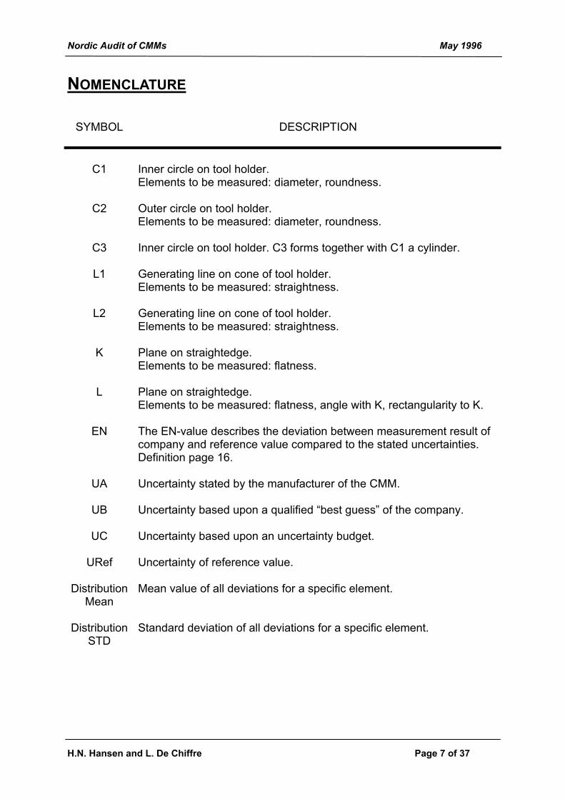
NOMENCLATURE
SYMBOL DESCRIPTION
C1
Inner circle on tool holder. Elements to be measured: diameter, roundness.
C2 Outer circle on tool holder. Elements to be measured: diameter, roundness.
C3 Inner circle on tool holder. C3 forms together with C1 a cylinder.
L1 Generating line on cone of tool holder. Elements to be measured: straightness.
L2 Generating line on cone of tool holder. Elements to be measured: straightness.
K Plane on straightedge. Elements to be measured: flatness.
L Plane on straightedge. Elements to be measured: flatness, angle with K, rectangularity to K.
EN The EN-value describes the deviation between measurement result of company and reference value compared to the stated uncertainties. Definition page 16.
UA Uncertainty stated by the manufacturer of the CMM.
UB Uncertainty based upon a qualified “best guess” of the company.
UC Uncertainty based upon an uncertainty budget.
URef Uncertainty of reference value.
Distribution Mean
Mean value of all deviations for a specific element.
Distribution STD
Standard deviation of all deviations for a specific element.

Nordic Audit of CMMs May 1996
H.N. Hansen and L. De Chiffre Page 8 of 37
1. AIM OF THE PROJECT Coordinate measuring machines (CMMs) are advanced measuring machines that are able to measure the geometry of complex items in three dimensions economically and accurately. The CMM is a very versatile measuring instrument and therefore used for a broad variety of measurement tasks. For some applications, which are difficult to measure, the CMM is the best measuring instrument available. CMMs are produced in different sizes and therefore they are used in many different types of industrial companies. In the Nordic countries it is estimated that there are more than 1000 CMMs. The fact that the CMM always will end up with some kind of measurement result makes it necessary to verify these results for instance in connection with ISO 9000. This documentation can be obtained by calibration of the CMM but also partly by participation in an audit. In an audit the industrial companies measure items that have been calibrated by a pilot laboratory. The measurement results are compared to the reference values and to the results of the other participants. The aim of this audit was therefore to map the ability of Nordic industrial companies to perform simple as well as complex measurements on CMMs and their ability to state uncertainties in coordinate measurements. The response to the companies had to be fast in order to make the results useful for the companies. At the same time the audit measurements should act as learning experiences bringing to the attention of the participants a variety of problems connected with coordinate measurements. The audit should therefore perform a check of both the CMM and the operator. The participants also should learn simple and fast methods for checking basic features of their CMM. The second part of the project was to build up a Nordic network of users of CMMs. This network should be led by the national laboratories and should enable the users of CMMs to come together easily and discuss practical and theoretical problems within coordinate metrology. The following number of industrial companies and institutes participated in the audit:
Country No of Companies
No of CMMs
Denmark 33 35 Finland 13 14 Sweden 8 8 Norway 4 4 Germany 1 1 Total 59 62
Table 1. Participants in the project. Besides the Nordic companies and laboratories, the Physikalisch-Technische Bundesanstalt from Germany has participated in the intercomparison.

Nordic Audit of CMMs May 1996
H.N. Hansen and L. De Chiffre Page 9 of 37
2. AUDIT ITEMS A necessary requirement for the audit items is that they have to be of high quality and long term stability. This is of importance to ensure the comparison of measurements performed over a period of approximately one year. Several possibilities regarding the audit items were discussed and the following conclusions were made: ❏ The audit items should comprise length measurements (dimensions), angle
measurements and measurements of geometrical quantities. ❏ The items for the measurement of geometrical quantities should possess form
deviations in the range 20 - 50 µm. ❏ The audit items should have a size allowing one person to handle them. This is
also important in connection with transportation of the packages between the participating companies.
❏ The audit items should not be too small taking into consideration that some very
large CMMs were participating. ❏ The price of the items should be reasonable. On this background it was decided to use the following items for the project:
ITEM FEATURES Tool holder for machine tools Dimensions, Geometrical quantities Gauge block 300 mm Dimensions Gauge block 50 mm Dimensions Straightedge Angles, Geometrical quantities Ring 50 mm Dimensions, Geometrical quantities
Table 2. Audit items for the project. A total of four packages were produced and circulated. The audit items are shown in figure 1. Regarding the stability of the items there is long experience with gauge blocks and granite straightedges. Also rings have proven to be stable. The tool holder is known to be extremely stable from the point of view of the workshop, but it has not yet been used for a metrological intercomparison. However the tool holder comprises a variety of geometrical features in one single element which makes it very useful in this project. Choosing the audit items described in table 2 allows a verification of the majority of geometrical quantities as described in table 3.

Nordic Audit of CMMs May 1996
H.N. Hansen and L. De Chiffre Page 10 of 37
Figure 1. The audit items.
Feature Tool holder Gauge block Straightedge Ring Dimension X X X Position X Angle X X Perpendicularity X Parallelism Straightness X Flatness X Roundness X X Cylindricity X Profile form Profile shape Coaxiality X Symmetry Circular runout Total runout
Table 3. Geometrical features measured on the audit items.
Nordic Audit of CMMs May 1996
H.N. Hansen and L. De Chiffre Page 11 of 37
The tool holder was purchased as a standard tool holder (SK/SA 50; DIN 69871 TEIL 1 FORM AD) and a special fixture for mounting was constructed. This was necessary to ensure the same fixing at all the companies. The steel gauge blocks were purchased as class 1. The granite straightedge was manufactured especially for this project with a rectangularity error of approximately 2 mm over a length of 300 mm. Two of the four straightedges had angles below 90° and two had angles above 90°. The steel ring was manufactured on a turning lathe with a three-lobed hole and form deviations varying between 10 µm and 40 µm. The maximum length covered by the items was approximately 300 mm. This is not enough to cover the working volume of a large CMM, but the items may then be measured in different positions.

Nordic Audit of CMMs May 1996
H.N. Hansen and L. De Chiffre Page 12 of 37
3. DESCRIPTION OF PRACTICAL CIRCULATION A total of four packages were circulated in the Nordic countries. In each country the national institute was responsible for the distribution list and the practical arrangements in connection with the circulation. See chapter 8 for addresses. In Denmark, Norway and Sweden each company had 2 weeks for the measurement. After having measured the audit items each company was responsible for transportation of the package to the next participating company. The transportation was arranged by courier or by mail. In Finland each company only had 1 week at its disposal for the measurements. Furthermore the audit items were forwarded to the participating companies by courier, and this person did not leave the package unattended at any time at the companies. Each package was thus followed by the same person during all measurements at all companies but without this person interfering with any instructions. This type of circulation requires detailed planning and a large amount of information to the participating companies regarding time schedule and eventual changes in plans. Of course machine breakdowns can never be foreseen, but only in a few cases the plan of circulation had to be changed. Finally the participating companies have to give high priority to the audit measurements in order to be able to keep the time schedule. The circulation principle of one person following the items is very time consuming and expensive and the results obtained seem not to differ significantly from the results obtained from the other circulation method used. Figure 2 shows the principle of the circulation of the four packages.
AUDIT
NO
1
2
3
4
CALIBRATION/RECALIBRATION OF AUDIT ITEMS
PACKAGE
DK
SF
S,N4 COMPANIES 8 COMPANIES
3 COMPANIES 8 COMPANIES
13 COMPANIES 5 COMPANIES
8 COMPANIES 10 COMPANIES
}
}
}
}
DK
DK D
Figure 2. Description of practical circulation in the Nordic countries.

Nordic Audit of CMMs May 1996
H.N. Hansen and L. De Chiffre Page 13 of 37
4. AUDIT PROCEDURES The audit procedures developed in connection with this project are enclosed in appendix 1. They reflect the aim of the project in checking both the machine and the operator. The measurements are split up into three phases as shown in figure 3. Phase I comprises measurements of tool holder, gauge blocks and straightedge according to a detailed procedure. In phase II the operator measures the ring using a procedure of his own choice. As background material he only has a technical drawing with one dimensional tolerance and one geometrical tolerance (appendix 1a). After finishing phase II the participant sends the results of the ring measurement to the national institute. Upon reception of these measurement results the national institute sends back a procedure for the measurement of the ring, and the company performs this measurement in phase III. After having finished all measurements the audit package is forwarded to the next participant. It must be emphasized that the sequence of measurement described in the procedures (tool holder, gauge blocks, straightedge and ring) not necessarily had to be followed. In fact some of the companies started by measuring the ring. This structure of procedures allows a verification of the machine (phases I and III) as well as a check of the operator (phases II and III). At the same time a quick response is given as to the operator’s skill. The experience from the project shows that this is a very popular structure in the opinion of the participants and no practical problems arose during the communication phase. It must be emphasized that all measurements results are based upon a least squares method. This method is not in harmony with ISO 1101.
COMMUNICATIONVIA FAX
PHASE IIIRING ACCORDING TO PROCEDURE
PHASE IIRING (COMPANY PROCEDURE)
PHASE ITOOL HOLDER, GAUGE BLOCKS
AND STRAIGHTEDGE ACCORDINGTO PROCEDURE
Figure 3. Principle of audit measurements.

Nordic Audit of CMMs May 1996
H.N. Hansen and L. De Chiffre Page 14 of 37
4.1 TOOL HOLDER The following elements were measured on the tool holder (details appendix 1a):
C1
C2
C3
L1
L2
L1
L2
C = circle L = line
No. Description (fig.4) No. of
points Results
1 Inner circle C1 (50 mm diameter) 16 equally distrib.
Diameter, centre coordinates (Y,Z)
2 Outer circle C2 (100 mm diameter) 16 equally distrib.
Diameter, centre coordinates (Y,Z)
3 Roundness of circles C1 and C2 --- Out of roundness
4 Total angle of cone. Cone measured with 3 circles
Each circle 16 equally distrib.
Angle °
5 Straightness of two generators L1 & L2
Each line 16
Straightness
6 Inner cylindricity of cylinder deter-mined by C1 and C3
Each circle 16 equally distrib.
Cylindricity
7 Coaxiality of cylinder no 6 compared to axis of alignment over 32 mm
--- Coaxiality
Figure 4. Elements to be measured on tool holder.

Nordic Audit of CMMs May 1996
H.N. Hansen and L. De Chiffre Page 15 of 37
The alignment of the tool holder was performed in two ways. 35 companies were asked to align the tool holder using two circles on the cone (see appendix 1a) and 24 companies were asked to align the tool holder using a cone (see appendix 1c). The effect of these different alignments are discussed in chapter 6.1.
4.2 GAUGE BLOCKS The measurements of the gauge blocks (300 mm and 50 mm) had to be performed in different orientations and positions in the working volume of the CMM a total of five different positions (see figure 5). The purpose was to get a statement about the positioning errors on the scales by measuring parallel to the axis, and to get a statement on the squareness error of the CMM in the XY-plane by measuring at angles of 35°. The alignment is described in appendix 1a. The gauge blocks should be placed as shown in figure 5, but in some cases the construction of the CMM does not allow for these positions. In these situations the operator had to indicate on the measurement report where the measurements were performed.
x
y
1 2
3
Scale Y-axis
3/4 of total length of X-axis
x
y
5 4
35�35�
Figure 5. Position of gauge blocks during measurements.
4.3 STRAIGHTEDGE The straightedge was measured according to the procedure described in appendix 1a. The position of the straightedge in the measuring plane of the CMM is illustrated in figure 6. The following elements are measured on the straightedge: flatness upper plane, flatness plane K, flatness plane L, angle between plane K and L and rectangularity of plane L to plane K over a specified length (appendix 1a).

Nordic Audit of CMMs May 1996
H.N. Hansen and L. De Chiffre Page 16 of 37
x
y
K
L
Figure 6. Position of straightedge on CMM.
4.4 RING The procedure for the measurement of the 50 mm ring (Phase III) is enclosed in appendix 1b. The diameter of the ring is determined as a two-point diameter and a 30-point diameter in three different heights in the ring. Furthermore the roundness based upon 30 points of the ring in the three heights is calculated.
4.5 REFERENCE VALUES The reference values of the audit items have been determined at the Technical University of Denmark, VTT (Finland) and Tampere University of Technology (Finland). The reference values as well as the reference uncertainties are listed in appendix 2. The reference values have been determined on the basis of several calibrations during the project period. Calibrations have been performed on a CMM strictly according to the procedures as well as on other equipment (form testers, roundness testers, 1D length comparators, surface roughness testers etc.) using a different number of sampling points, different evaluation software etc. (see appendix 2 for overview). For all items and all features there was extremely good agreement between the results obtained on CMM and result obtained by other methods. The differences were within the measuring uncertainty. The calibrations were performed independently from each other and the calibration results were not compared until the end of the project. Furthermore a very good stability of all items were observed during the project. No changes were observed in the calibrated values within the measuring uncertainty.

Nordic Audit of CMMs May 1996
H.N. Hansen and L. De Chiffre Page 17 of 37
5. UNCERTAINTIES In this project the companies were asked to state three uncertainties for all their measurements. These uncertainties were: A) Uncertainty as stated by the manufacturer of the CMM B) Uncertainty based upon a qualified “best guess” from the user of the CMM C) Uncertainty based upon an uncertainty budget All deviation charts in appendix 4 are based upon the uncertainty UB (“Best guess”) since this was the only uncertainty almost every company could state. However it is observed that stating UB for geometrical quantities as angle or coaxiality gives severe problems to the user, who has no feeling of how good he is actually measuring. The uncertainty UA is stated especially for the measurement of the tool holder, the gauge blocks and the ring. However it is used uncritically for evaluating uncertainties of geometrical quantities as for instance roundness and straightness. This shows that the participants clearly are not familiar with the use of the length measuring uncertainty as stated by the manufacturer of the CMMs. The uncertainty UC was stated in less than 40% of the cases and not for all elements. Especially the geometrical quantities of the tool holder and straightedge gave problems. For all companies who stated an uncertainty the EN-value was calculated. The EN-value is defined as:
EN U Ucompany reference
company reference
=−
+
Result Result2 2
The EN-value describes the difference between the result obtained by the company and the reference value compared to the stated uncertainties (ref.1). If EN<1 there is good agreement between the two results, and if EN>1 then the results are not identical. Of course a very big stated uncertainty Ucompany also causes small EN-values. As described in the EAL Guideline G17 “Coordinate Measuring Machine Calibration” (ref.2) two approaches to the determination of uncertainties are recommended: the comparator approach and the error synthesis method. The comparator method requires calibrated reference standards to be used in the comparator measurement. The error synthesis method on the other hand requires assessment and knowledge of the parametric errors of the CMM. Both methods give uncertainty budgets resulting in an overall measuring uncertainty for a specific task.

Nordic Audit of CMMs May 1996
H.N. Hansen and L. De Chiffre Page 18 of 37
An effort has to be made in the field of uncertainty estimation in coordinate metrology and therefore the established network already has held 2 seminars (one in Denmark and one in Finland) on this subject. At these seminars the different approaches to the problems of uncertainty budgeting in coordinate measurements were presented and proposed methods as how to carry through practical evaluations were given. Material from these seminars can be ordered through the respective contact persons in Finland and Denmark (see chapter 8).

Nordic Audit of CMMs May 1996
H.N. Hansen and L. De Chiffre Page 19 of 37
6. DATA ANALYSIS In this chapter the results of the audit are presented and discussed. The measurement results are found in the following appendices: • Appendix 3: Measurement results from each company. One sheet per company.
The companies are anonymous. • Appendix 4: Graphs showing deviations from reference values for each company
and each element. In these graphs the stated uncertainty is based upon a “best guess” by the company.
• Appendix 5: Histograms showing the statistical distributions of the deviations from reference values for each element.
The presentation will be divided according to the four different types of items (tool holder, gauge blocks, straightedge and ring), and each element will be discussed. Table 4 shows the statistics on the measurements of the companies. If a company did not follow the procedure or did not measure at all, this has been registered as “did not measure”. However all performed measurements are of course evaluated even though single elements are missing. This means that the graphs may contain a number of CMMs differing from the numbers in table 4.
ItemNo. of
CMM's who measured
No. of CMM's who
didn't measure
TOTALCMM's who measured
(%)
CMM's who didn't
measure (%)
TOTAL (%)
Tool Holder 57 5 62 92 8 100Gauge Block 50 mm * 61 1 62 98 2 100Gauge Block 300 mm * 61 1 62 98 2 100Straightedge ** 57 5 62 92 8 100Ring phase 3 *** 56 6 62 90 10 100
* 1 company only measured the gauge blocks in two positions** 4 of the 5 companies measured flatness but not angle and perpendicularity*** The 6 companies did not follow the procedure exactly
Table 4. Statistics on measurements by companies.

Nordic Audit of CMMs May 1996
H.N. Hansen and L. De Chiffre Page 20 of 37
6.1 TOOL HOLDER 57 companies measured the tool holder and the results are shown in appendices 4 and 5. The deviations of the measurement results of the companies compared to the reference values are shown in appendix 4. For each element the number of companies whose EN-value is below 1, above 1 and the number of companies not stating any uncertainty UB is determined, and the results are shown in table 5. From table 5 it is seen that diameter and straightness are measured with good results at the companies. The circularity, angle of cone, cylindricity and coaxiality all show smaller percentages for EN<1. Especially the coaxiality seems here to be critical. These geometrical quantities generally are difficult to measure but also difficult to evaluate using the CMM-software. Here detailed procedures do not overcome the problems of interpretation of the software. Looking at the deviation charts (appendix 4) it is seen that the number of outlayers is increasing with the difficulty of the measuring task. The same is seen from table 5 (EN>1, no uncertainty). For the diameters most of the participants stated an uncertainty based upon a best guess, but for the geometrical quantities the number of uncertainty statements decreased. Especially for the angle of the cone a very low number of participants had a “best guess” as to the uncertainty. Regarding the two other uncertainties only a few participants stated these.
Element EN<1 (%) EN>1 (%)No
uncertainty (%)
Distribution Mean [µm]
Distribution STD [µm]
Inner diameter C1 76 12 12 0.2 3.0Outer diameter C2 63 23 14 -0.9 3.5Circularity inner diameter C1 61 21 18 4.4 6.4Circularity outer diameter C2 56 26 18 2.3 5.4Angle of Cone [°] 53 7 40 0.0000° 0.0017°Straightness of line L1 79 2 19 1.0 2.6Straightness of line L2 77 4 19 1.4 2.8Cylindricity 58 23 19 2.7 4.1Coaxiality 37 42 21 17.6 44.5
Table 5. Overview of measurement results on tool holder. For each element on the tool holder a histogram was produced showing the distribution of the deviations from the reference value. For the diameters a gaussian distribution is seen (example figure 7) and the mean value and standard deviation can be seen in table 5. The straightness measurements show a normal distribution and from table 5 it is seen that no special problems arose during these measurements. Another situation is observed in the roundness measurements (example figure 8). Here a clear one-tailed distribution is observed. This can be explained by the fact that the measurement is difficult and that the result is

Nordic Audit of CMMs May 1996
H.N. Hansen and L. De Chiffre Page 21 of 37
influenced by many parameters since the measurand is small. Looking at the coaxiality a one-tailed distribution is also seen but this is explained by the fact that this result is very dependent upon the quality of the alignment (figure 9). The coaxiality is given only by a positive value in the results. If the direction of the coaxiality was to be taken into account a two-tailed distribution might be the result. Two methods of alignment were used for the measurement of the tool holder. Figure 10 shows the distribution of the coaxiality using the two different alignments. It is seen that there is a difference between the two different types of alignment, but the differences may also come from difficulties arising from the correct use of the software.
0
5
10
15
20
25
-20 -18 -16 -14 -12 -10 -8 -6 -4 -2 0 2 4 6 8 10 12 14 16 18 20Deviation from ref. value [µm]
No.
of C
MM
s
C1
Figure 7. Histogram showing the measurements of 50 mm diameter on tool holder.

Nordic Audit of CMMs May 1996
H.N. Hansen and L. De Chiffre Page 22 of 37
0
5
10
15
20
25
-20 -18 -16 -14 -12 -10 -8 -6 -4 -2 0 2 4 6 8 10 12 14 16 18 20Deviation from ref. value [µm]
No.
of C
MM
s
Figure 8. Histogram showing the measurement of roundness on tool holder.
0
5
10
15
20
25
-20 -18 -16 -14 -12 -10 -8 -6 -4 -2 0 2 4 6 8 10 12 14 16 18 20Deviation from ref. value [µm]
No.
of C
MM
s
A-B
A B
Figure 9. Histogram showing the measurements of coaxiality on tool holder.

Nordic Audit of CMMs May 1996
H.N. Hansen and L. De Chiffre Page 23 of 37
-2 0 2 4 6 8 10 12 14 16 18 20
Two circlesCone
0
1
2
3
4
5
6
7N
o. o
f CM
Ms
Deviation from ref. value [µm]
Figure 10. Histogram showing the effect of alignment on coaxiality. Back: tool holder
aligned as cone. Front: tool holder aligned using two circles. CONCLUSION From the results of the tool holder it may be concluded that increasing the difficulty of the measuring task directly influences the results obtained by the participants. Simple features as dimensions or straightness seems to cause no severe problems. This can be seen by the deviation charts and by the histograms produced. The histograms show a gaussian distribution. However increasing the level of difficulty by introducing geometrical quantities as roundness, cone measurement, cylindricity and coaxiality immediately can be observed in the results. The histograms show a one-tailed distribution to the positive side indicating that these quantities usually are measured too big. This is explained by the fact that the measurand is very small causing too big measurement results. Difficulties were observed on the side of uncertainty estimation. 22 companies stated some kind of uncertainty based upon an uncertainty budget. For the uncertainty based upon a “best guess” almost all participants stated an uncertainty. However regarding the geometrical quantities as the angle of cone many participants gave up. As for the uncertainty stated by the manufacturer some participants stated it and others did not.

Nordic Audit of CMMs May 1996
H.N. Hansen and L. De Chiffre Page 24 of 37
6.2 GAUGE BLOCKS 61 companies measured the gauge blocks and the results are shown in appendices 4 and 5. The deviations of the measurement results of the companies compared to the reference values are shown in appendix 4. For each element the number of companies whose EN-value is below 1, above 1 and the number of companies not stating any uncertainty UB is determined, and the results are shown in table 6. It is seen that the participants all measured the gauge blocks with high accuracy. Generally the 50 mm gauge block was measured with a better result than the 300 mm gauge block. The large number of companies with an EN-value below 1 must also be seen in the light of the reference uncertainty being 80 nm (calibration by laserinterferometer). This indicates that the CMMs of the participants were generally in good conditions regarding the positioning errors in the two axis directions and the squareness between these two axes. Looking at the deviation charts (appendix 4) it is seen that the picture of the measurements does not change dramatically between the different positions and the different lengths of gauge blocks. The same is seen from table 6. Especially positions 1 and 2 are interesting since the gauge blocks have been measured in the same axis direction but with different distances to the axis (see figure 5). No clear difference is observed in the measurement results. It is typical that the outlayers in all positions are caused by the same machines. This indicates that the gauge blocks are very useful for this type of investigation.
Element EN<1 (%) EN>1 (%)No
uncertainty (%)
Distribution Mean [µm]
Distribution STD [µm]
50 mm - Position 1 79 10 11 0.1 1.7300 mm - Position 1 62 23 15 -0.7 7.150 mm - Position 2 74 13 13 0.0 2.0300 mm - Position 2 62 23 15 0.2 3.550 mm - Position 3 78 11 11 0.1 1.3300 mm - Position 3 64 23 13 -0.3 2.750 mm - Position 4 74 15 11 -0.3 1.7300 mm - Position 4 71 18 11 -0.3 2.650 mm - Position 5 73 16 11 -0.4 2.0300 mm - Position 5 76 13 11 -0.4 3.0
Table 6. Overview of measurement results on gauge blocks.

Nordic Audit of CMMs May 1996
H.N. Hansen and L. De Chiffre Page 25 of 37
Looking at the deviation charts it is clear that the participants have a much better feeling regarding the uncertainties in length measurement. Table 6 also indicates this. This is of course based upon their prior knowledge to the length measurement uncertainty which is generally stated by the manufacturer of the CMM. For each gauge block and each position a histogram was produced showing the distribution of the deviations from the reference value. Histograms are shown in appendix 5. For all measurements a clear gaussian distribution was observed with a very little number of outlayers in each case. The mean values and standard deviation are shown in table 6 indicating larger standard deviations for the 300 mm gauge block than for the 50 mm gauge block in all positions. This can be explained by the sensitivity of the long gauge block to temperature (handling, radiation etc.). Figures 11 and 12 show two histograms for the 50 mm gauge block and the 300 mm gauge block both in position 4.
0
5
10
15
20
25
-20 -18 -16 -14 -12 -10 -8 -6 -4 -2 0 2 4 6 8 10 12 14 16 18 20
Deviation from ref. value [µm]
No.
of C
MM
s
X
Y
50
Figure 11. Histogram showing the measurements of 50 mm gauge block.

Nordic Audit of CMMs May 1996
H.N. Hansen and L. De Chiffre Page 26 of 37
0
5
10
15
20
25
-20 -18 -16 -14 -12 -10 -8 -6 -4 -2 0 2 4 6 8 10 12 14 16 18 20
Deviation from ref. value [µm]
No.
of C
MM
s
X
Y
300
Figure 12. Histogram showing the measurements of 300 mm gauge block. CONCLUSION The measurement of gauge blocks in the audit proved to be a success establishing the traceability of the CMM. All results follow a gaussian distribution indicating that alignment and measuring procedure were good. Measurement of gauge blocks in different positions on the CMM allows for the verification of different scale errors and squareness errors. The audit results show that estimation of uncertainties of simple length measurements is no problem for industry.

Nordic Audit of CMMs May 1996
H.N. Hansen and L. De Chiffre Page 27 of 37
6.3 STRAIGHTEDGE 57 companies measured the straightedge and the results are shown in appendices 4 and 5. The deviations of the measurement results of the companies compared to the reference values are shown in appendix 4. For each element the number of companies whose EN-value is below 1, above 1 and the number of companies not stating any uncertainty UB is determined, and the results are shown in table 7. For the flatness measurements it is seen that the participants measure very good. However fir the angle and the perpendicularity a decreasing accuracy is observed. Especially the perpendicularity seems to give problems for the participants. Here use of the software is the problem since the perpendicularity is calculated using the measured planes. Looking at the deviation charts (appendix 4) it is seen that problems arise when the perpendicularity is calculated. Some companies have difficulties in determining whether the angle is more or less than 90°. These deviations are so large that they are not shown in the deviation charts. Problems concerning uncertainty estimation are seen especially for the angle and the perpendicularity. This is the same tendency as observed on the tool holder.
Element EN<1 (%) EN>1 (%)No
uncertainty (%)
Distribution Mean [µm]
Distribution STD [µm]
Flatness plane K 79 6 15 1.1 1.9Flatness plane L 75 10 15 0.2 2.7Flatness upper plane 69 16 15 0.5 1.8Angle 90° 54 8 38 -0.0353 0.4500°Perpendicularity 36 28 36 -1.6 4.6
Table 7. Overview of measurement results on straightedge. For each of the elements a histogram was produced showing the distribution of the deviations from the reference value (appendix 5). For the three flatness measurements a gaussian distribution is observed but it has to be noted that for plane K the distribution is one-tailed because the flatness is small (figures 13 and 14). This is the same observation which was made for some geometric quantities on the tool holder. The standard deviations increase when the out-of-flatness increases.

Nordic Audit of CMMs May 1996
H.N. Hansen and L. De Chiffre Page 28 of 37
Regarding the perpendicularity a normal distribution is also observed but a large number of outlayers introduces a relatively large standard deviation.
0
5
10
15
20
25
-20 -18 -16 -14 -12 -10 -8 -6 -4 -2 0 2 4 6 8 10 12 14 16 18 20
Deviation from ref. value [µm]
No.
of C
MM
s
Figure 13. Histogram showing flatness of plane K on straightedge.
0
5
10
15
20
25
-20 -18 -16 -14 -12 -10 -8 -6 -4 -2 0 2 4 6 8 10 12 14 16 18 20
Deviation from ref. value [µm]
No.
of C
MM
s
Figure 14. Histogram showing flatness of upper plane on straightedge.

Nordic Audit of CMMs May 1996
H.N. Hansen and L. De Chiffre Page 29 of 37
0
5
10
15
20
25
30
-0.0
100
-0.0
080
-0.0
060
-0.0
040
-0.0
020
0.00
00
0.00
20
0.00
40
0.00
60
0.00
80
0.01
00
Deviation from ref. value [°]
No.
of C
MM
s
90 °
Figure 15. Histogram showing 90° angle on straightedge. CONCLUSION The conclusion of the measurements of the straightedge is that flatness is a geometrical quantity that is measured without problems by the majority of the participants. The absolute value of the flatness is of importance to the deviations obtained by the companies (one-tailed distribution vs. gaussian distribution). The angle of 90° is determined well by the participants except in a few cases where there have been problems in determining whether the angle is more or less than 90°. The uncertainty statements are very poor for the angle. The perpendicularity however shows a large standard deviation and relatively many results far away from the reference value. This indicates that correct use of the software is a problem for this feature.

Nordic Audit of CMMs May 1996
H.N. Hansen and L. De Chiffre Page 30 of 37
6.4 RING 56 companies measured the ring according to the procedure (appendix 1b) and the results are shown in appendices 4 and 5. The results obtained during phase II (measurement by the company’s own procedure) are not discussed here since the procedures chosen vary a lot. The results however are reported in appendix 3. The deviations of the measurement results of the companies compared to the reference values are shown in appendix 4 For each element the number of companies whose EN-value is below 1, above 1 and the number of companies not stating any uncertainty UB is determined, and the results are shown in table 8. No clear differences are seen between the two-point diameter results and the 30-point diameter results from the deviation charts. Table 8 however shows that the companies are a little bit better at measuring the 30-point diameter than the two-point diameter. This can be explained by the large form error of the ring making the obtained two-point diameter result sensitive to the orientation of the ring. The number of uncertainty statements for the diameters (two-point as well as 30-point diameter) is quite constant but decreases for the roundness measurements. This was also seen for the tool holder.
Element EN<1 (%) EN>1 (%)No
uncertainty (%)
Distribution mean [µm]
Distribution std [µm]
Diameter 2 points Z=-2 65 21 14 -0.4 2.5Diameter 2 points Z=-12.5 63 23 14 -0.7 2.5Diameter 2 points Z=-23 70 16 14 0.2 2.9Diameter 30 points Z=-2 72 14 14 -0.6 3.1Diameter 30 points Z=-12.5 72 14 14 -0.4 2.2Diameter 30 points Z=-23 72 14 14 -0.3 2.5Circularity Z=-2 63 18 19 0.7 6.0Circularity Z=-12.5 67 12 21 1.5 6.1Circularity Z=-23 61 18 21 1.8 3.7
Table 8. Overview of measurement results on ring. For each measured element on the ring a histogram was produced showing the distribution of the deviations from the reference value. The histograms are collected in appendix 5. No significant differences are observed between the distributions of the two-point diameter measurements and the 30-point diameter measurements. They are all normally distributed with an almost constant standard deviation (table 8). Furthermore no difference is seen between the different heights in the ring that were measured. Figures 16 and 17 show an example of histograms from the diameter measurements in the middle belt of the ring. The histograms for the roundness show the same characteristics as for the tool holder, namely a one-tailed

Nordic Audit of CMMs May 1996
H.N. Hansen and L. De Chiffre Page 31 of 37
distribution. The trend is not as clear for the heights Z=-2 mm (top) and Z=-12.5 mm (middle) but for the bottom Z=-23 mm the one-tailed distribution is very clear (figure 18). In table 8 the standard deviations for the circularity decrease from the top belt to the bottom belt. This is explained by single large deviations observed in these data.
0
5
10
15
20
25
-20 -18 -16 -14 -12 -10 -8 -6 -4 -2 0 2 4 6 8 10 12 14 16 18 20
Deviation from ref. value [µm]
No.
of C
MM
s
50
Z=-12.5 mm2 points
Figure 16. Histogram showing the measurement of two-point diameter in middle belt
of ring.

Nordic Audit of CMMs May 1996
H.N. Hansen and L. De Chiffre Page 32 of 37
0
5
10
15
20
25
-20 -18 -16 -14 -12 -10 -8 -6 -4 -2 0 2 4 6 8 10 12 14 16 18 20
Deviation from ref. value [µm]
No.
of C
MM
s
50
Z=-12.5 mm30 points
Figure 17. Histogram showing the measurement of 30-point diameter in middle belt
of ring.
0
5
10
15
20
25
-20 -18 -16 -14 -12 -10 -8 -6 -4 -2 0 2 4 6 8 10 12 14 16 18 20
Deviation from ref. value [µm]
No.
of C
MM
s
Z=-23 mm
Figure 18. Histogram showing the measurement of 30-point roundness in bottom
belt of ring.

Nordic Audit of CMMs May 1996
H.N. Hansen and L. De Chiffre Page 33 of 37
CONCLUSION The conclusion of the measurement results of the ring is that the distribution of the results of the diameter measurements are not affected dramatically using 2-point probing or 30 point probing and doing so in different belts with different form deviations. The hole is triangular making the measurement more or less insensitive to the orientation of the ring but nevertheless a bigger standard deviation would have been expected for the two-point diameters. The measurement results regarding roundness showed the same trend as seen also with the tool holder: a one-tailed distribution is obtained for geometrical quantities. Because of the relatively large form deviations in the top and middle belt of the ring the distributions here are not one-tailed, but for the bottom belt of the ring the trend is clear. Generally a large number of companies stated uncertainties for the diameter measurements but also for the roundness measurements a large part of the participants stated their uncertainty.
Nordic Audit of CMMs May 1996
H.N. Hansen and L. De Chiffre Page 34 of 37
7. HOW TO INTERPRET THE RESULTS OF THE AUDIT For the participants it is interesting to compare their measurement results to the reference values and to the other participating companies. This can most easily be done by regarding the deviation charts (appendix 4) where all results for all elements are shown. It is of course interesting to see how far away from the reference value one is placed and to see if the stated uncertainty UB looks sensible. For the gauge blocks this can directly be used as a very simple check of the axes of the CMM. Regarding the geometrical quantities the companies now have a feeling how they measure these compared to a reference laboratory. A comparison with the other participants is also possible looking at the deviation charts, and especially a comparison regarding the uncertainties shows large differences between the companies. For the companies not stating any uncertainties at all the audit should encourage those to establish a knowledge as to their uncertainties. A comparison with the other participants may help in this process. For those companies stating uncertainties which are obviously too big, the audit should be a possibility of getting more realistic uncertainties. Companies obtaining measurement results far away from the reference value but stating small uncertainties clearly have a problem which should be corrected. All in all the audit results of each company can be used for a revision of the CMM, the stated uncertainties and the handling of measurements of geometrical quantities.

Nordic Audit of CMMs May 1996
H.N. Hansen and L. De Chiffre Page 35 of 37
8. NORDIC NETWORK IN COORDINATE METROLOGY As a part of this project a Nordic network in coordinate metrology has been established. The activities in the network have until now comprised 2 seminars in Finland and 3 seminars in Denmark. Both Swedish and Norwegian interested companies have participated in the seminars in Denmark. A Nordic conference on coordinate metrology is held on June 11 1996 in Copenhagen with the purpose of connecting the national networks into a Nordic network. At the time of writing the network counts approximately 120 persons in Denmark, 150 in Finland, 10 in Sweden and 10 in Norway. The 4 audit packages are still available for measurements at the national laboratories. The contact persons are as follows: COUNTRY CONTACT
PERSON ADDRESS PHONE & FAX
Denmark Leonardo De Chiffre
Institut for Procesteknik, Bygning 425, DTU, DK-2800 Lyngby
☎ +45 45 88 25 22 Fax +45 45 93 01 90
Denmark Hans Nørgaard Hansen
Institut for Procesteknik, Bygning 425, DTU, DK-2800 Lyngby
☎ +45 45 88 25 22 Fax +45 45 93 01 90
Finland Heikki Lehto VTT, Manufacturing Technology, Metallimiehenkuja 6, P.O.Box 1702 SF-02044 VTT
☎ +358 0 45 61 Fax +358 0 460 627
Finland Heikki Tikka Tampere University of Technology, Production Engineering P.O.Box 589 SF-33101 Tampere
☎ +358 31 36 52 719 Fax +358 31 36 52 753
Sweden Mikael Frennberg
SP Box 857 S-50115 Borås
☎ +46 33 16 50 00 Fax +46 33 10 69 73
Sweden Agneta Jakobsson
SP Box 857 S-50115 Borås
☎ +46 33 16 50 00 Fax +46 33 10 69 73
Norway Helge Karlsson
Justervesnet Box 6832 St. Olavs Plass N-0130 Oslo
☎ +47 22 20 02 26 Fax +47 22 20 77 72

Nordic Audit of CMMs May 1996
H.N. Hansen and L. De Chiffre Page 36 of 37
9. CONCLUSION In this project “Nordic audit of coordinate measuring machines” an industrial intercomparison of coordinate measuring machines (CMMs) in the Nordic countries was carried out. The project has been carried out in the period October 1994 to May 1996. A total of 59 industrial companies with a total of 62 CMMs have participated in the project measuring an audit package consisting of 5 items. The five audit items were chosen representing a variety of dimensions, angles and other geometrical quantities. The elements were a tool holder, two gauge blocks, a straightedge and a ring. During the audit these items have proven to be of high stability. A set of measurement procedures giving instructions on how to measure the items was produced and each participant received a copy before reception of the audit package. The procedures were also thought to be a practical tool for the companies to perform interim checks of their machines after having finished this audit. Histograms of the measurement results show that the procedures were adequate for this project. A total of four audit packages circulated in the Nordic countries allowing each company to keep a package for 1-2 weeks. The items were measured in three steps: the tool holder, the gauge blocks and the straightedge were measured according to the procedures. Then the ring was measured using a procedure of the operator’s own choice. After a communication phase with the national laboratory the ring was finally measured according to a given procedure. During the entire project this construction gave no problems. The big interest and motivation of the participants being the main reason for this. The different measurement results were discussed in chapter 6. A brief summary must include the fact that increasing the level of difficulty from simple length measurements to more complex geometrical quantities gives severe problems for some of the participants. This is the fact even though the participants measured according to the described procedure. It is seen from the reports from the companies that uncertainties in CMM measurement is a very big problem for the industrial companies. Even though one of the uncertainties was based upon a “best guess”, many participants didn’t even report this uncertainty. For each company a comparison of their measuring ability with the reference laboratory and other Nordic companies is now possible. A network regarding CMMs has been created in the Nordic countries.

Nordic Audit of CMMs May 1996
H.N. Hansen and L. De Chiffre Page 37 of 37
10. REFERENCES 1) WECC document 15-1992. WECC Interlaboratory Intercomparisons, Western
European Calibration Cooperation, 1992. 2) EAL Guideline G17. Coordinate Measuring Machine Calibration, European
Cooperation for Accreditation of Laboratories, 1st ed., 1995