Embed Size (px)
Citation preview

THE WORLD’S FASTEST DUCTING
NO
RD
FAB
DU
CTI
NG
CAT
ALO
GU
E
C l i p p e d D u c t i n g
Ducting
&FLANGED DUCTWORK
www.nordfabducting.co.uk

Ducting
SLIP DUCT
QUICK-FIT CLIP
QUICK-FIT CLIP
STANDARD BEND
ROLLED EDGE
O-RING
SUCTION / MACHINEHOOD CONNECTION
Nordfab QF and FL ducting form a key part of your dust collection installation. Choose either QF clipped or FL flanged in standard weld-free galvanised form or plasma welded for superior internal surface finish. Nordfab can guide you from design to installation, with first class service and parts availability.
Nordfab QF Clipped and FL Flanged ductingQF clipped and FL flanged ducting offers a complete range of diameters and accessories for easy-to-fix professional installations. Manufactured from galvanised steel, the recently introduced plasma welded range with smoother internal surfaces and greatly enhanced leak resistance offers an unbeatable solution for all general purpose dust extraction duties.
The Quick-Fit clip features a generously dimensioned sealing gasket held firmly in place by positive over-centre clamping action over the rolled collars at the duct ends to be joined. For added security a locking pin may be inserted.
FL flanged ducting is supplied with pre-assembled and drilled loose flanges, for ease of alignment during installation.
QF for fast installation with no special tools, no painting, flexible working
Easy to assemble installation components
Neat slip duct connections to adapt and adjust ducting on site during installation
FL offers additional security of bolted flanged connections for more rigorous applications
Plasma welded straight ducts for smoother surface and enhanced leak resistance
Easy to extend or take apart completely for cleaning, reconfiguring or relocation
Full range of accessories and installation components
Adapters available to connect to and extend all other duct systems
ATEX certified CARZ back pressure flaps for explosion protection
All you need from one comprehensive, tried and tested range
Stainless steel available
2 www.nordfabducting.co.uk
Who Uses Quick-Fit
• Woodworking
• Furniture
• Metalworking
• Concrete
• Recycling
• Plastics
• Textiles
• Powder, Bulk and Solids
• Agriculture
• Paper
• Chemical
• Ventilation
• And many more
Ducting
Using the air volume chartThis chart allows you to choose the correct duct size for the air volume that is required. Different materials need to be conveyed at different velocities to prevent the material from falling out of the air stream. For example, wood chips and saw dust flow well between 18 and 22 m/s. Referring to the chart, a 100mm duct will convey622 m3/h at 22 m/s. This indicates that a 100 mm pick-up on a machine will use 622 m3/h from the filtering system. Or working in reverse, if you know that a machine will require approximately 650 m3/h to remove the waste, then you should design a 100 mm duct for the application.
3www.nordfabducting.co.uk
Consistent: The strength, quality and versatility of Nordfab QF ducting make it suitable for applications far beyondlocal exhaust ventilation (LEV - dust extraction).
Versatile: Clipped ducting in several diameters from 100mm to 710mm; flanged version up to 1000mm diameter. Materials typically bright galvanised steel or stainless steel in thicknesses ranging from 0.7 to 2.0mm, for heavy duty applications.
Strong: Independent tests by the ATEX Notified Body FTZU confirm a maximum allowable internal pressure underexplosive conditions (Pred) in excess of 0.8bar, making it very suitable for systems handling inflammable or explosive dusty atmospheres, which have explosion protection measures.
Sizing Nordfab Ducting SystemNordfab offers assistance to customers who have never designed a ductingsystem. We can assist you with determining the correct duct size and configuration for optimal air flow. Please call your local representative for assistance.
Range of duct air flow volumes [m3/h] Ø
[mm]10
[m/s]12
[m/s]15
[m/s]18
[m/s]20
[m/s]22
[m/s]25
[m/s]27
[m/s]29
[m/s]31
[m/s]100 283 339 424 509 566 622 707 763 820 877125 442 530 663 795 884 972 1105 1193 1281 1370140 554 665 831 998 1108 1219 1385 1496 1607 1718160 724 869 1086 1303 1448 1592 1810 1954 2099 2244180 916 1099 1374 1649 1832 2015 2290 2473 2657 2840200 1131 1357 1697 2036 2262 2488 2827 3054 3280 3506224 1419 1702 2128 2554 2837 3121 3547 3831 4114 4398250 1767 2121 2651 3181 3534 3888 4418 4771 5125 5478300 2545 3054 3817 4580 5089 5598 6362 6871 7380 7889315 2806 3367 4208 5050 5611 5172 7014 7575 8136 8697350 3464 4156 5195 6235 6927 7620 8659 9352 10045 10737400 4524 5429 6786 8143 9048 9953 11310 12215 13119 14024450 5726 5871 8588 10306 11451 12569 14314 15459 16604 17749500 7069 8482 10603 12724 14137 15551 17672 19085 20499 21913560 8867 10640 13300 15960 17734 19507 22167 23940 25714 27487630 11222 13466 16833 20200 22444 24689 28055 30300 32544 34788710 14253 17104 21380 25656 28506 31357 35633 38483 41334 44185
Nordfab QF wraps up your ventilation requirementsLeakproof: With plasma welded longitudinal seals, tightly clipped joints incorporating high quality flexible and resealable gaskets, leakage under positive or negative pressure is almost eliminated, making Nordfab QF suitable for ducting applications that must conform to DW/144 class A, B and C for leakage.
Clean: All internal surfaces are smooth and free from ledges
Accessible: All parts including duct sections, branches, bends and hoods are located by means of quick release clips – easily dismantled and re-fitted for inspection and maintenance. The requirements of HVCA Guide TR/19 (Sects 3 & 7) are easily fulfilled by design, making Nordfab QF ideal for kitchen extract systems in accordance with HVCA DW/172 principles of good design.

Ducting
4 www.nordfabducting.co.uk

Ducting
5www.nordfabducting.co.uk

Ducting
Slip
duc
t
Put O-ring on cut duct, slide slip duct over, cut piece of duct
5
Snap clip over O-ring and one end of slip duct
6
Finished connection with the slip duct
7
Mark distance to be spanned less 100 mm
2
Use O-ring provided and mark for cut
3
Cut the duct
4
Measure distance to be spanned
1
Inst
ruct
ions
for
inst
alla
tion
of
slip
duc
t
6 www.nordfabducting.co.uk

Ducting
Slip duct L = 300 mmØ
mmItem no. Thickness
mmWeight
kg
100 20000-100 0.7 0.35
125 20000-125 0.7 0.42
140 20000-140 0.7 0.49
160 20000-160 0.7 0.56
180 20000-180 0.7 0.63
200 20000-200 0.7 0.70
224 20000-224 0.7 0.84
250 20000-250 0.7 0.91
300 20000-300 0.7 0.98
315 20000-315 0.7 1.05
350 20000-350 0.7 1.19
400 20000-400 0.9 2.6
450 20000-450 0.9 2.7
500 20000-500 0.9 3.1
560 20000-560 0.9 3.5
630 20000-630 0.9 3.9
710 20000-710 0.9 4.4
L
Type
Ø
30106-315 e.g.:
Seal will be installed and folded over at the factory
While clamping down, slowly tuck extra seal underneath the opposing side of clamp
QF clip
Slip duct
O-ring
Type
Ø
20000 315 e.g.:
STOCK RANGE
Type
Ø
30100-315 e.g.:Quick Fit ClipØ
mmItem no.
100 30100-100
125 30100-125
140 30100-140
160 30100-160
180 30100-180
200 30100-200
224 30100-224
250 30100-250
300 30100-300
315 30100-315
350 30100-350
400 30100-400
450 30100-450
500 30100-500
560 30100-560
630 30100-630
710 30100-710
Rubber O-ringØ
mmItem no.
100 30106-100
125 30106-125
140 30106-140
160 30106-160
180 30106-180
200 30106-200
224 30106-224
250 30106-250
300 30106-300
315 30106-315
350 30106-350
400 30106-400
450 30106-450
500 30106-500
560 30106-560
630 30106-630
710 30106-710
7www.nordfabducting.co.uk

Ducting
STOCK RANGE S
trai
ght
duc
t Q
F Straight QF duct L=1470mm Nom.Ø
mmItem no. Thickness
mmWeight
kg
100 20915-100 0.7 2.52
125 20915-125 0.7 3.08
140 20915-140 0.7 3.64
160 20915-160 0.7 4.06
180 20915-180 0.7 4.62
200 20915-200 0.7 5.18
224 20915-224 0.7 5.60
250 20915-250 0.7 6.44
300 20915-300 0.7 7.70
315 20915-315 0.7 7.98
350 20915-350 0.7 8.96
400 20915-400 0.9 13.6
450 20915-450 0.9 15.3
500 20915-500 0.9 17.0
560 20915-560 0.9 18.7
630 20915-630 0.9 21.4
710 20915-710 0.9 24.1
Type
Ø
20915-315 e.g.:
8 www.nordfabducting.co.uk

Ducting
*Straight FL duct L=1470 mm Nom.Ø
mmItem no. Thickness
mmWeight
kg
560 20115-560 0.9 23.0
630 20115-630 0.9 26.2
710 20115-710 0.9 29.5
800 20115-800 0.9 35.4
900 20115-900 0.9 39.8
1000 20115-1000 0.9 44.6
*Straight FL duct L=2000 mmØ
mmItem no. Thickness
mmWeight
kg
560 20112-560 0.9 33.16
630 20112-630 0.9 37.17
710 20112-710 0.9 41.23
800 20112-800 0.9 48.67
900 20112-900 0.9 53.82
1000 20112-1000 0.9 59.57
FlangeDuct Ø
mmItem no. Pitch circle Ø
mmExternal Ø
mmNo. of holes Thickness
mmWeight
kg
315 30015-315 349 377 8 4.0 1.25
350 30015-350 387 413 8 4.0 1.40
400 30015-400 438 464 12 4.0 1.55
450 30015-450 488 514 12 4.0 1.75
500 30015-500 538 564 12 4.0 1.95
560 30015-560 600 625 12 4.0 2.15
630 30015-630 670 695 16 4.0 2.40
710 30015-710 750 775 16 4.0 2.70
800 30015-800 848 884 16 4.0 4.10
900 30015-900 948 984 16 4.0 4.60
1000 30015-1000 1050 1090 16 4.0 5.30
Type
Ø
20112-710 e.g.:
Type
Ø
20115-900 e.g.:
Type
Ø
30015-560 e.g.:
STOCK RANGE S
traight duct flanged and flages
*This item is made to order
*This item is made to order
9www.nordfabducting.co.uk

10
Ducting
STOCK RANGE
60° Pressed bendsØ
mmItem no. r
mmL1 L2 H Thickness
mmWeight
kg
100 21006-100 100 95 165 210 0.5 0.2
125 21006-125 125 100 185 235 0.5 0.3
140 21006-140 135 90 190 230-240 0.7 0.5
160 21006-160 160 105 215 260-275 0.7 0.5
180 21006-180 180 110 230 280-290 0.7 0.8
30° Pressed bendsØ
mmItem no. r
mmL1 L2 H Thickness
mmWeight
kg
100 21003-100 100 30 105 135 0.5 0.2
125 21003-125 125 30 125 150 0.5 0.3
140 21003-140 135 35 130 160 0.7 0.4
160 21003-160 160 35 135 170 0.7 0.5
180 21003-180 180 35 145 185 0.7 0.6
30°
45°
60°
90°
r = 1 x Øx = angle size (3,4,6,9)
90° Pressed bendsØ
mmItem no. r
mmL1 L2 H Thickness
mmWeight
kg
100 21009-100 100 130 130 180 0.5 0.3
125 21009-125 125 158 158 216 0.5 0.5
140 21009-140 135 165 165 235 0.7 0.7
160 21009-160 160 190 190 265 0.7 0.8
180 21009-180 180 205 205 295 0.7 1.0
45° Pressed bendsØ
mmItem no. r
mmL1 L2 H Thickness
mmWeight
kg
100 21004-100 100 50 125 165 0.5 0.3
125 21004-125 125 55 140 185 0.5 0.3
140 21004-140 135 60 150 190 0.7 0.4
160 21004-160 160 65 160 215 0.7 0.5
180 21004-180 180 70 170 235 0.7 0.7
Pre
ssed
ben
ds Q
F
Type
Ø
2100X-100 e.g.:
www.nordfabducting.co.uk

Ducting
STOCK RANGE S
egmented bends Q
F
30° Segmented bendsØ
mm Item no. rmm
L1 L2 H Thick-ness
Weightkg
200 21003-200 300 98 367 417 0.7 1.19224 21003-224 336 100 374 430 0.7 1.37250 21003-250 375 102 382 445 0.7 1.71300 21003-300 450 111 413 488 0.7 2.37315 21003-315 472 112 417 496 0.7 2.53350 21003-350 525 114 427 514 0.7 3.01400 21003-400 600 118 440 540 0.7 3.08450 21003-450 675 124 463 575 0.7 3.96500 21003-500 750 129 483 608 0.7 4.77560 21003-560 840 135 502 642 0.7 6.08630 21003-630 945 142 528 686 0.7 6.86710 21003-710 1065 150 559 736 0.7 7.73
45° Segmented bendsØ
mm Item no. rmm
L1 L2 H Thick-ness
Weightkg
200 21004-200 300 170 411 482 0.7 1.57224 21004-224 336 177 426 505 0.7 1.82250 21004-250 375 184 444 532 0.7 2.30300 21004-300 450 203 491 597 0.7 3.24315 21004-315 472 207 500 611 0.7 3.46350 21004-350 525 216 521 645 0.7 4.27400 21004-400 600 229 552 694 0.7 4.22450 21004-450 675 245 592 751 0.7 5.51500 21004-500 750 261 629 806 0.7 6.69560 21004-560 840 277 669 867 0.7 8.48630 21004-630 945 298 719 942 0.7 9.71710 21004-710 1065 322 777 1028 0.7 10.93
60° Segmented bendsØ
mm Item no. rmm
L1 L2 H Thick-ness
Weightkg
200 21006-200 300 251 435 521 0.7 1.95224 21006-224 350 264 457 554 0.7 2.26250 21006-250 375 278 482 590 0.7 2.88300 21006-300 450 312 541 671 0.7 4.11315 21006-315 472 320 555 691 0.7 4.39350 21006-350 525 339 587 738 0.7 5.45
400 21006-400 600 365 632 805 0.7 5.34450 21006-450 675 396 685 880 0.7 7.03500 21006-500 750 425 737 953 0.7 8.57560 21006-560 840 458 793 1036 0.7 10.91630 21006-630 945 498 863 1136 0.7 12.44710 21006-710 1065 545 943 1251 0.7 14.07
90° Segmented bendsØ
mm Item no. rmm
L1 = L2mm
H Thick-ness
Weightkg
200 21009-200 300 417 517 0.7 2.72224 21009-224 350 447 559 0.7 3.16250 21009-250 375 480 605 0.7 4.06300 21009-300 450 551 701 0.7 5.85315 21009-315 472 570 728 0.7 6.26350 21009-350 525 613 788 0.7 7.81400 21009-400 600 675 875 0.7 7.60450 21009-450 675 742 967 0.7 10.04500 21009-500 750 808 1058 0.7 12.32560 21009-560 840 884 1164 0.7 15.78630 21009-630 945 975 1290 0.7 18.05710 21009-710 1065 1079 1434 0.7 20.34
r = 1.5 x Øx = angle size (3,4,6,9)
Type
Ø
2100X-200 e.g.:
45°30°
60° 90°
11www.nordfabducting.co.uk
L1 = L2

12
Ducting
STOCK RANGE
30° Segmented bends (FL)Ø
mmItem no. Thickness
mmWeight
kg
560 21113-560 0.7 12.26
630 21113-630 0.7 14.71
710 21113-710 0.7 16.87
800 21113-800 0.7 22.10
900 21113-900 0.7 25.06
1000 21113-1000 0.7 29.67
45° Segmented bends (FL)Ø
mmItem no. Thickness
mmWeight
kg
560 21114-560 0.7 15.00
630 21114-630 0.7 18.05
710 21114-710 0.7 20.16
800 21114-800 0.7 26.48
900 21114-900 0.7 31.08
1000 21114-1000 0.7 36.24
60° Segmented bends (FL)Ø
mmItem no. Thickness
mmWeight
kg
560 21116-560 0.7 17.18
630 21116-630 0.7 20.78
710 21116-710 0.7 24.00
800 21116-800 0.7 30.86
900 21116-900 0.7 36.56
1000 21116-1000 0.7 43.36
90° Segmented bends (FL)Ø
mmItem no. Thickness
mmWeight
kg
560 21119-560 0.7 21.57
630 21119-630 0.7 26.21
710 21119-710 0.7 31.11
800 21119-800 0.7 40.17
900 21119-900 0.7 48.06
1000 21119-1000 0.7 57.60
Seg
men
ted
bend
s FL Type
Ø
21114-710 e.g.:
Standard radius r = 1.5 x Ø
www.nordfabducting.co.uk

Ducting
Cut in branch (QF)Ø1
mmItem no. Thickness
mmWeight
kg
100 QI Ø2 100 0.7 0.9
125 QI Ø2 125 0.7 0.9
140 QI Ø2 140 0.7 0.9
160 QI Ø2 160 0.7 0.9
180 QI Ø2 180 0.7 1.3
200 QI Ø2 200 0.7 1.6
224 QI Ø2 224 0.7 1.8
250 QI Ø2 250 0.7 1.9
300 QI Ø2 300 0.7 2.2
315 QI Ø2 315 0.7 2.3
350 QI Ø2 350 0.7 2.8
400 QI Ø2 400 0.9 5.3
450 QI Ø2 450 0.9 8.2
500 QI Ø2 500 0.9 9.9
560 QI Ø2 560 0.9 12.0
630 QI Ø2 630 0.9 13.7
710 QI Ø2 710 0.9 15.5
Double branch (QF)Ø
mmItem no. Thickness
mmWeight
kg
100 QT100.xxx 0.7 1.4
125 QT125.xxx 0.7 1.5
140 QT140.xxx 0.7 1.6
160 QT160.xxx 0.7 1.5
180 QT180.xxx 0.7 1.7
200 QT200.xxx 0.7 2.6
224 QT224.xxx 0.7 3.0
250 QT250.xxx 0.7 3.2
300 QT300.xxx 0.7 4.0
315 QT315.xxx 0.7 4.4
350 QT350.xxx 0.7 5.6
400 QT400.xxx 0.9 11.3
450 QT450.xxx 0.9 12.8
500 QT500.xxx 0.9 17.3
560 QT560.xxx 0.9 21.0
630 QT630.xxx 0.9 24.0
710 QT710.xxx 0.9 27.0
Ø2 must be smaller than or equal to Ø1
Double branch (FL)Ø
mmItem no. Thickness
mmWeight
kg
560 QT560FL.xxx 0.9 26.0
630 QT630FL.xxx 0.9 32.0
710 QT710FL.xxx 0.9 43.1
800 QT800FL.xxx 0.9 53.2
900 QT900FL.xxx 0.9 72.6
1000 QT1000FL.xxx 0.9 89.7
Cut in branch (FL)Ø1
mmItem no. Thickness
mmWeight
kg
560 QI Ø2FL. Ø1 0.9 12.7
630 QI Ø2FL. Ø1 0.9 15.8
710 QI Ø2FL. Ø1 0.9 19.3
800 QI Ø2FL. Ø1 0.9 27.6
900 QI Ø2FL. Ø1 0.9 34.0
1000 QI Ø2FL. Ø1 0.9 42.0
Ø2
Ø1
QI 100 315 e.g.:
Ø1
Ø2
Ø3
Ø4
e.g. QT315 250 300 250
Double branch Q
F and FL C
ut in branch QF and FL
MADE TO ORDER
L4 = ( Ø4 / 2 ) +58mmL2 = ( Ø2 / 2 ) +58mmL1 = ( Ø2 x 2 ) +236mmØ3 must be smaller than or equal to Ø1Ø2 or Ø4 must be smaller than or equal to Ø3
108
L 2
13www.nordfabducting.co.uk

14
Ducting
Y - Branch (QF)Ø1
mmItem no. Thickness
mmWeight
kg
100 QB100 Ø2 Ø2 0.7 0.5
125 QB125 Ø2 Ø2 0.7 0.7
140 QB140 Ø2 Ø2 0.7 0.9
160 QB160 Ø2 Ø2 0.7 1.1
180 QB180 Ø2 Ø2 0.7 1.4
200 QB200 Ø2 Ø2 0.7 1.6
224 QB224 Ø2 Ø2 0.7 1.9
250 QB250 Ø2 Ø2 0.7 2.3
300 QB300 Ø2 Ø2 0.7 3.0
315 QB315 Ø2 Ø2 0.7 3.6
350 QB350 Ø2 Ø2 0.7 4.6
400 QB400 Ø2 Ø2 0.9 7.5
450 QB450 Ø2 Ø2 0.9 9.4
500 QB500 Ø2 Ø2 0.9 11.6
560 QB560 Ø2 Ø2 0.9 12.5
630 QB630 Ø2 Ø2 0.9 14.3
710 QB710 Ø2 Ø2 0.9 16.1
Branch (QF)Ø1
mmItem no. Thickness
mmWeight
kg
100 QG100.Ø2 Ø3 0.7 1
125 QG125.Ø2 Ø3 0.7 1.1
140 QG140.Ø2 Ø3 0.7 1.4
160 QG160.Ø2 Ø3 0.7 1.7
180 QG180.Ø2 Ø3 0.7 2.2
200 QG200.Ø2 Ø3 0.7 2.6
224 QG224.Ø2 Ø3 0.7 3.0
250 QG250.Ø2 Ø3 0.7 3.3
300 QG300.Ø2 Ø3 0.7 4.5
315 QG315.Ø2 Ø3 0.7 5.1
350 QG350.Ø2 Ø3 0.7 7.0
400 QG400.Ø2 Ø3 0.9 11.1
450 QG450.Ø2 Ø3 0.9 14.1
500 QG500.Ø2 Ø3 0.9 18.5
560 QG560.Ø2 Ø3 0.9 22.4
630 QG630.Ø2 Ø3 0.9 25.6
710 QG710.Ø2 Ø3 0.9 28.9
L = Ø1 + 100 mmØ2 must be smaller than or equal to Ø1
Branch (FL)Ø
mmItem no. Thickness
mmWeight
mm
560 QG560FL.Ø2 Ø3 0.9 32.0
630 QG630FL.Ø2 Ø3 0.9 41.0
710 QG710FL.Ø2 Ø3 0.9 47.0
800 QG800FL.Ø2 Ø3 0.9 58.0
900 QG900FL.Ø2 Ø3 0.9 71.0
1000 QG1000FL.Ø2 Ø3 0.9 85.0
Y - Branch (FL)Ø1
mmItem no. Thickness
mm
560 QB560FL Ø2 Ø2 0.9
630 QB630FL Ø2 Ø2 0.9
710 QB710FL Ø2 Ø2 0.9
800 QB800FL Ø2 Ø2 0.9
900 QB900FL Ø2 Ø2 0.9
1000 QB1000FL Ø2 Ø2 0.9
L1
L2
108
L2 = ( Ø2 / 2 ) +58L1 = ( Ø2 x 2 ) +236Ø3 must be smaller than or equal to Ø1Ø2 must be smaller than or equal to Ø3
Ø1
Ø2
Ø3
QG 315 250 300 e.g.:
Ø1
Ø2
Ø2
QB 315 250 250 e.g.:
Y b
ranc
h Q
F an
d FL
Bra
nch
QF
and
FLMADE TO ORDER
Ø1
58
Ø2
Ø2
L
60o
www.nordfabducting.co.uk

Ducting
Suction hoodØ1
mmItem no. Thickness
mm
100 23012.X. Ø1 0.7
125 23012.X. Ø1 0.7
140 23012.X. Ø1 0.7
160 23012.X. Ø1 0.7
180 23012.X. Ø1 0.7
200 23012.X. Ø1 0.7
224 23012.X. Ø1 0.7
250 23012.X. Ø1 0.7
300 23012.X. Ø1 0.7
315 23012.X. Ø1 0.7
350 23012.X. Ø1 0.7
400 23012.X. Ø1 0.9
450 23012.X. Ø1 0.9
500 23012.X. Ø1 0.9
560 23012.X. Ø1 0.9
630 23012.X. Ø1 0.9
710 23012.X. Ø1 0.9No. of connections (from 2 to 8) and shape (round or rectangular) must be specified
Type
No. of connections
Ø1
23012 3 250 e.g.:
Please specify- The actual A,B and Ø dimentions- The positions of the connection spigot- The type of connection spigot (QF, spiro or raw end)
Transition rectangular to roundØ
mmItem no. Thickness
mm
100 22035.100 0.9
125 22035.125 0.9
140 22035.140 0.9
160 22035.160 0.9
180 22035.180 0.9
200 22035.200 0.9
224 22035.224 0.9
250 22035.250 0.9
300 22035.300 0.9
315 22035.315 0.9
350 22035.350 0.9
400 22035.400 0.9
450 22035.450 0.9
500 22035.500 0.9
560 22035.560 0.9
630 22035.630 0.9
710 22035.710 0.9
Type
A
B
23035 500 400 e.g.:
Suction hood
Transition rectangular to roundMADE TO ORDER
15www.nordfabducting.co.uk

16
Ducting
Floor sweepØ
mmItem no. Thickness
mmWeight
kg
100 23011.100 0.9 4.0
125 23011.125 0.9 4.2
140 23011.140 0.9 4.4
160 23011.160 0.9 4.7
180 23011.180 0.9 5.0
1
Reducer (QF)Ø1
mmItem no. Thickness
mmWeight
kg
125 QR125 Ø3 0.7 0.2
140 QR140 Ø3 0.7 0.2
160 QR160 Ø3 0.7 0.2
180 QR180 Ø3 0.7 0.3
200 QR200 Ø3 0.7 0.4
224 QR224 Ø3 0.7 0.5
250 QR250 Ø3 0.7 0.6
300 QR300 Ø3 0.7 0.8
315 QR315 Ø3 0.7 0.9
350 QR350 Ø3 0.7 1.0
400 QR400 Ø3 0.9 1.8
450 QR450 Ø3 0.9 2.1
500 QR500 Ø3 0.9 2.3
560 QR560 Ø3 0.9 2.5
630 QR630 Ø3 0.9 2.9
710 QR710 Ø3 0.9 3.3
L = (Ø1 - Ø3) + 50 + (2 x 58) mm
L = 450 mmA = 150 mmB = 300 mmC = 75 mm
B A
C
L
Reducer (FL)Ø1
mmItem no. Thickness
mmWeight
kg
560 QR560FL.Ø3 0.9 6.9
630 QR630FL.Ø3 0.9 8.0
710 QR710FL.Ø3 0.9 12.9
800 QR800FL.Ø3 0.9 16.1
900 QR900FL.Ø3 0.9 18.2
1000 QR1000FL.Ø3 0.9 20.4
Floo
r sw
eep
QF
Red
ucer
QF
and
FL
Ø1
Ø3
QR 315 250 e.g.:
Type
Ø
23011-180 e.g.:
MADE TO ORDER
www.nordfabducting.co.uk
Ø1
Ø3

Ducting
L = 50mm
End cap
End cap (QF)Ø
mmItem no. Thickness
mmWeight
kg
100 22012 0.7 0.13
125 22012 0.7 0.18
140 22012 0.7 0.22
160 22012 0.7 0.26
180 22012 0.7 0.35
200 22012 0.7 0.40
224 22012 0.7 0.49
250 22012 0.7 0.62
300 22012 0.7 0.88
315 22012 0.7 1.15
350 22012 0.7 1.60
400 22012 0.9 2.12
450 22012 0.9 2.63
500 22012 0.9 3.20
560 22012 0.9 3.86
630 22012 0.9 4.41
710 22012 0.9 4.98
Type
Ø
22012-315 e.g.:
End cap with bird mesh (QF)Ø
mmItem no. Thickness
mmWeight
kg
100 22022 0.7 0.13
125 22022 0.7 0.18
140 22022 0.7 0.22
160 22022 0.7 0.26
180 22022 0.7 0.35
200 22022 0.7 0.40
224 22022 0.7 0.49
250 22022 0.7 0.62
300 22022 0.7 0.88
315 22022 0.7 1.15
350 22022 0.7 1.60
400 22022 0.9 2.12
450 22022 0.9 2.63
500 22022 0.9 3.20
560 22022 0.9 3.86
630 22022 0.9 4.41
710 22022 0.9 4.98
L = 50mm
Wire mesh
Type
Ø
22022-315 e.g.:
End cap w
ith bird mesh Q
FMADE TO ORDER
End cap Q
F
17www.nordfabducting.co.uk

18
Ducting
Type
Ø
22010-315 e.g.:
Type
Ø
22014-315 e.g.:
Machine adapter (QF)Ø
mmItem no. Thickness
mmWeight
mm100 22014 0.7 0.40125 22014 0.7 0.48140 22014 0.7 0.58160 22014 0.7 0.66180 22014 0.7 0.74200 22014 0.7 1.13224 22014 0.7 1.26250 22014 0.7 1.41300 22014 0.7 1.71315 22014 0.7 1.80350 22014 0.7 2.00400 22014 0.9 2.90450 22014 0.9 3.30500 22014 0.9 3.70560 22014 0.9 4.10630 22014 0.9 4.70710 22014 0.9 5.30
Smooth adapter (QF)Ø
mmItem no. Thickness
mmWeight
kg100 22010 0.7 0.20125 22010 0.7 0.24140 22010 0.7 0.29160 22010 0.7 0.33180 22010 0.7 0.37200 22010 0.7 0.56224 22010 0.7 0.64250 22010 0.7 0.70300 22010 0.7 0.80315 22010 0.7 0.90350 22010 0.7 1.00400 22010 0.9 1.40450 22010 0.9 1.60500 22010 0.9 1.90560 22010 0.9 2.10630 22010 0.9 2.40710 22010 0.9 2.70
Sm
ooth
ada
pter
QF
Mac
hine
ada
pter
QF
MADE TO ORDER
Step edge adapter (QF)Ø
mmItem no. Thickness
mmWeight
kg100 22009.100 0.7 0.20125 22009.125 0.7 0.24140 22009.140 0.7 0.29160 22009.160 0.7 0.33180 22009.180 0.7 0.37200 22009.200 0.7 0.56224 22009.224 0.7 0.64250 22009.250 0.7 0.70300 22009.300 0.7 0.80315 22009.315 0.7 0.90350 22009.350 0.7 1.00400 22009.400 0.9 1.40450 22009.450 0.9 1.60500 22009.500 0.9 1.90560 22009.560 0.9 2.10630 22009.630 0.9 2.40710 22009.710 0.9 2.70
Type
Ø
22009-315 e.g.:
Hose adapter (QF)Ø
mmItem no. Thickness
mmWeight
mm100 22013.100 0.7 0.40125 22013.125 0.7 0.48140 22013.140 0.7 0.58160 22013.160 0.7 0.66180 22013.180 0.7 0.74200 22013.200 0.7 1.13224 22013.224 0.7 1.26250 22013.250 0.7 1.41300 22013.300 0.7 1.71315 22013.315 0.7 1.80350 22013.350 0.7 2.00400 22013.400 0.9 2.90450 22013.450 0.9 3.30500 22013.500 0.9 3.70560 22013.560 0.9 4.10630 22013.630 0.9 4.70710 22013.710 0.9 5.30
Type
Ø
22013-315 e.g.:

Ducting
Cut in boot shoe (QF)Ø1
mmItem no. Thickness
mmWeight
kg
100 CBS.100.Ø2 0.9 0.9
125 CBS.125.Ø2 0.9 0.9
140 CBS.140.Ø2 0.9 0.9
160 CBS.160.Ø2 0.9 0.9
180 CBS.180.Ø2 0.9 1.3
200 CBS.200.Ø2 0.9 1.6
224 CBS.224.Ø2 0.9 1.7
250 CBS.250.Ø2 0.9 1.9
300 CBS.300.Ø2 0.9 2.1
315 CBS.315.Ø2 0.9 2.3
350 CBS.350.Ø2 0.9 2.8
400 CBS.400.Ø2 0.9 5.3
450 CBS.450.Ø2 0.9 8.2
500 CBS.500.Ø2 0.9 9.9
560 CBS.560.Ø2 0.9 11.1
630 CBS.630.Ø2 0.9 12.5
710 CBS.710.Ø2 0.9 14.1
L = Ø1 x 2 +236 mmL1 = Ø1 x 0.5 + Ø2 x 0.5 + 58 mmThe boot cut is always placed in the centre
Boot shoe (QF)Ø1
mmItem no. Thickness
mmWeight
kg
100 TBS.100.Ø2 Ø3 0.9 1.0
125 TBS.125.Ø2 Ø3 0.9 1.1
140 TBS.140.Ø2 Ø3 0.9 1.2
160 TBS.160.Ø2 Ø3 0.9 1.5
180 TBS.180.Ø2 Ø3 0.9 1.9
200 TBS.200.Ø2 Ø3 0.9 2.3
224 TBS.224.Ø2 Ø3 0.9 2.6
250 TBS.250.Ø2 Ø3 0.9 3.0
300 TBS.300.Ø2 Ø3 0.9 3.7
315 TBS.315.Ø2 Ø3 0.9 4.2
350 TBS.350.Ø2 Ø3 0.9 5.6
400 TBS.400.Ø2 Ø3 0.9 9.4
450 TBS.450.Ø2 Ø3 0.9 12.2
500 TBS.500.Ø2 Ø3 0.9 16.4
560 TBS.560.Ø2 Ø3 0.9 18.4
630 TBS.630.Ø2 Ø3 0.9 20.7
710 TBS.710.Ø2 Ø3 0.9 23.3
The boot cut is always placed in the centre
Cut in boot shoe (FL)Ø1
mmItem no. Thickness
mmWeight
kg
560 CBS.560FL.Ø2 0.9 12.7
630 CBS.630FL.Ø2 0.9 15.8
710 CBS.710FL.Ø2 0.9 19.3
800 CBS.800FL.Ø2 0.9 27.6
900 CBS.900FL.Ø2 0.9 34.0
1000 CSB.1000FL.Ø2 0.9 42.0
45
50 50
Ø2
Ø1
Ø1
Ø2
CBS 300 250 e.g.:
Ø1
Ø2
Ø3
TSB 315 224 300 e.g.:
Boot shoe Q
F and FL C
ut in boot shoe QF and FL
MADE TO ORDER
45
Ø1
Ø2
Ø3
L
L1
Boot shoe (FL)Ø1
mmItem no. Thickness
mmWeight
kg
560 TBS.560FL.Ø2 Ø3 0.9 23.2
630 TBS.630FL.Ø2 Ø3 0.9 34.2
710 TBS.710FL.Ø2 Ø3 0.9 42.8
800 TBS.800FL.Ø2 Ø3 0.9 52.7
900 TBS.900FL.Ø2 Ø3 0.9 64.4
1000 TSB.1000FL.Ø2 Ø3 0.9 76.4
19www.nordfabducting.co.uk

20
Ducting
Please call Dantherm Filtration for specification
MADE TO ORDER
Low velocity discharge cowl (QF)Ød mm
ØD mm
Thicknessmm
Amm
Bmm
C (RHS)mm
100 140 0.7 400 150 20x20
125 180 0.7 500 150 25x25
140 180 0.7 560 150 20x20
160 200 0.7 640 150 20x20
180 250 0.7 720 150 30x30
200 250 0.7 800 150 25x25
250 315 0.7 1000 150 30x30
315 350 0.7 1260 250 20x20
350 400 0.7 1750 250 25x25
400 450 0.9 1750 250 25x25
450 500 0.9 1750 250 25x25
500 560 0.9 2000 250 30x30
BA
t
t
Ød
ØD
3030
Low velocity discharge cowl (FL)Ød mm
ØD mm
Thicknessmm
Amm
Bmm
C (RHS)mm
560 630 0.9 2240 350 30x30
630 710 0.9 2520 350 40X40
710 800 0.9 2840 350 40X40
800 900 0.9 3200 350 50X50
900 1000 0.9 3600 350 50X50
1000 1100 0.9 4000 350 50X50
Low
vel
ocit
y di
scha
rge
cow
l QF
and
FL
Custom Manifold
Cus
tom
man
ifol
d
www.nordfabducting.co.uk

Ducting
Back pressure flap type CARZ (QF) (FL)
Ø mm
Lmm
Bmm
Weightkg
Lmm
Bmm
Weightkg
160 488 260 13.0 488 260 14.0180 510 280 15.0 510 280 17.0200 528 300 19.0 528 300 20.0250 578 350 20.0 578 350 21.0315 643 415 27.0 643 415 29.0350 780 450 34.0 780 450 36.0400 830 500 42.0 728 500 44.0450 880 550 45.0 778 550 48.0500 930 600 49.0 830 600 52.0560 1068 660 54.0 1068 660 67.0630 1138 730 62.0 1138 730 75.0710 1218 810 68.0 1218 810 83.0800 1308 900 91.0900 1408 1000 99.0
1000 1508 1100 109.0
ATEXProtection system Certified no.
FTZU 02ATEX 0271and
FTZU 04ATEX 0090
MADE TO ORDER B
ack pressure flap CA
RZ Q
F and FL
21www.nordfabducting.co.uk
1 2 3 4
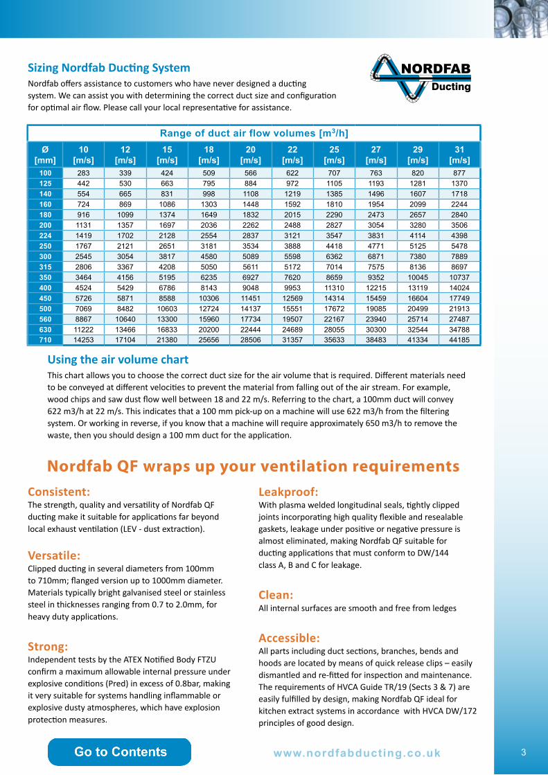
AIRFLOW DIRECTION EXPLOSION DIRECTION
Explosion without CARZ
Explosion with CARZ
The CARZ back pressure flap (or non-return damper) is designed to prevent the damaging effects of an explosion in a vessel such as a dust collector from travelling along a duct. It is robustly constructed and quick acting and certified as a protective system in accordance with ATEX Directive 94/9/EC. Suitable for St1 dust only.
After explosion
Dampers Ø 500mm & below = 2m straight ductDampers Ø 560mm & above = 5m straight duct

22
Ducting
Manual diverter valve (QF)Ø
mmItem no. L1
mmL2mm
bmm
Weightkg
100 23500 401 64 88 13.6
125 23500 428 64 106 17.1
140 23500 453 64 124 19.5
160 23500 478 64 142 23.2
180 23500 502 64 159 26.1
200 23500 577 89 177 33.6
250 23500 665 101 222 47.0
315 23500 773 115 279 64.9
350 23500 816 115 310 75.4
400 23500 938 140 354 101.3
450 23500 1000 140 398 123.2
500 23500 1122 169 442 142.2
Automatic diverter valve (QF)Ø
mmItem no. L1
mmL2mm
bmm
Weightkg
100 23600 401 64 88 19.1
125 23600 428 64 106 23.9
140 23600 453 64 124 26.7
160 23600 478 64 142 30.5
180 23600 502 64 159 34.3
200 23600 577 89 177 38.2
250 23600 665 101 222 50.6
315 23600 773 115 279 91.8
350 23600 816 115 310 142.6
400 23600 938 140 354 183.6
450 23600 1000 140 398 155.0
500 23600 1122 169 442 190.3
Flanged version availableItem no. 23500 XXX
Flanged version availableItem no. 23600XXX
Man
ual d
iver
ter
valv
e Q
FA
utom
atic
div
erte
r va
lve
QF
MADE TO ORDER
Ø1
Ø2
Ø3
23600 315 250 250 e.g.:
Ø1
Ø2
Ø3
23500 315 250 250 e.g.:
www.nordfabducting.co.uk

Ducting
= 990mm
Type
Ø
23041-315 e.g.:
Sound attenuation in dB at frequency bands
HzØ mm 63 125 250 500 1000 2000 4000 8000
100 2 10 17 34 50 50 49 28
125 1 7 14 30 50 50 37 21
140 1 5 12 27 50 39 24 14
160 1 5 12 27 50 39 24 14
180 2 4 11 21 37 28 16 10
200 2 4 11 21 37 28 16 10
224 1 3 9 19 38 19 11 9
250 1 3 9 19 38 19 11 9
300 3 6 13 20 19 10 6 7
315 3 6 13 20 19 10 6 7
350 4 5 10 17 13 6 6 8
400 4 5 10 17 13 6 6 8
450 4 4 10 14 8 4 6 6
500 4 4 10 14 8 4 6 6
Silencer (QF)
Ø mm 100 125 140 160 180 200 224 250 300 315 350 400 450 500
Item no. 23041 23041 23041 23041 23041 23041 23041 23041 23041 23041 23041 23041 23041 23041
Silencer Q
FACCESSORIES
23www.nordfabducting.co.uk

24
Ducting
ACCESSORIES
Type
Ø
8604003-315 e.g.:
Type
Ø
8604004-045 e.g.:
Flex
ible
pol
yure
than
e ho
se a
nd c
lam
p Flexible polyurethane hose Ø
mmItem no. Thickness
mmWeightgr/mtr
38 8604003038 0.5 166
45 8604003045 0.5 200
51 8604003051 0.55 260
63 8604003063 0.55 320
76 8604003076 0.6 440
82 8604003082 0.6 480
89 8604003089 0.6 520
102 8604003102 0.65 660
114 8604003114 0.65 720
127 8604003127 0.65 800
140 8604003140 0.65 900
152 8604003152 0.7 1100
160 8604003160 0.7 1160
178 8604003178 0.7 1300
203 8604003203 0.7 1400
229 8604003229 0.7 1580
254 8604003254 0.8 1880
305 8604003305 0.8 2250
315 8604003315 0.8 2390
Flexible hose clamp Ø
mmItem no. Ducting size*
30-45 8604004038 38
32-50 8604004045 45
40-60 8604004051 51
60-80 8604004063 63
70-90 8604004076 76
70-90 8604004076 82
80-100 8604004089 89
90-110 8604004102 102
110-130 8604004114 114
120-140 8604004127 127
130-150 8604004140 140
140-160 8604004152 152
150-170 8604004160 160
170-190 8604004180 180
200-220 8604004203 203
230-250 8604004229 229
260-280 8604004254 254
258-355 8604004305 305* ducting size - Nominal bore- buying unit is 1 meter
www.nordfabducting.co.uk

Ducting
Manual energy saving damper (QF)Ø
mmItem no. A max
mmB
mmC
mmD
mmE
mmWeight
kg
100 23075 329 208 150 125 82 1.3
125 23075 382 233 175 125 94 1.6
140 23075 412 248 190 125 102 1.8
160 23075 462 287 220 125 117 2.4
180 23075 501 298 240 125 127 2.8
200 23075 543 318 260 125 137 3.1
250 23075 653 378 320 125 167 4.3
315 23075 793 453 395 125 204 5.9
350 23075 860 500 430 120 225 7.5
400 23075 975 560 480 120 255 9.1
450 23075
500 23075
Type
Ø
23075-315 e.g.:
Manual energy saving dam
per QF
ACCESSORIES
Metalflex hose Ø IDmm
ODmm
Bend Radius
Weightkg/m
Standard Length mm
20 24 100 0.35 10
40 45 155 0.69 10
60 66 215 1.01 10
80 86 270 1.34 10
100 107 300 2.01 10
120 127 380 2.40 10
140 149 430 3.10 10
150 159 460 3.32 10
160 169 490 3.54 10
180 189 545 3.97 10
200 211 560 5.37 5
250 261 700 6.68 5
Metalflex hose
Can be delivered with:Standard Seal - temperature range up to approx. +120 CGlass Fibre Seal - temperature range up to approx, +400 C
25www.nordfabducting.co.uk

26
Ducting
Type
Ø
3000-315 e.g.:Automatic energy saving damper (QF)
Ø mm
Item no. A mm
Bmm
Cmm
Dmm
Weightkg
100 23073 405 160 125 130 4.4
125 23073 445 190 125 152 5.2
140 23073 480 200 125 160 5.6
160 23073 520 220 125 175 6.2
180 23073 560 240 125 185 7.2
200 23073 650 260 125 210 8.4
250 23073 840 441 300 360 19.4
315 23073 970 506 300 392 24.6
350 23073 1040 541 300 410 28.1
400 23073 1140 591 300 435 34.5
450 23073 1240 641 300 460 40.0
500 23073 1340 691 300 485 45.0
560 23073
630 23073
710 23073
1 pc
. Pne
umat
ic
cylin
der
2 pc
s. P
neum
atic
cy
linde
rs
Automatic energy saving damper (FL)Ø
mmItem no. A
mmB
mmC
mmD
mmWeight
kg
250 23373 840 441 300 360 19.4
315 23373 970 506 300 392 24.6
350 23373 1040 541 300 410 28.1
400 23373 1140 591 300 453 34.5
450 23373 1240 641 300 460 40.0
500 23373 1340 691 300 485 45.0
560 23373 1460 751 300 515 54.0
630 23373 1730 821 300 575 68.0
710 23373 1808 901 300 615 88.0
2 pc
s. P
neum
atic
cy
linde
rs
ACCESSORIES A
utom
atic
ene
rgy
savi
ng d
ampe
r Q
F an
d FL
Plain channel 41x41
Item no.
8460020001
Framework bracketMBP 304 Item no.
8460020015
Channel spring nut long type m10
Item no.
8460020006
Inst
alla
tion
par
ts
Standard supply is 220V240V supply available (Item no. 23074XXX)
M10 beam clamp FL2
Item no.
8460004010
Pipe bracing
Item no.
1810101900
www.nordfabducting.co.uk
Ducting
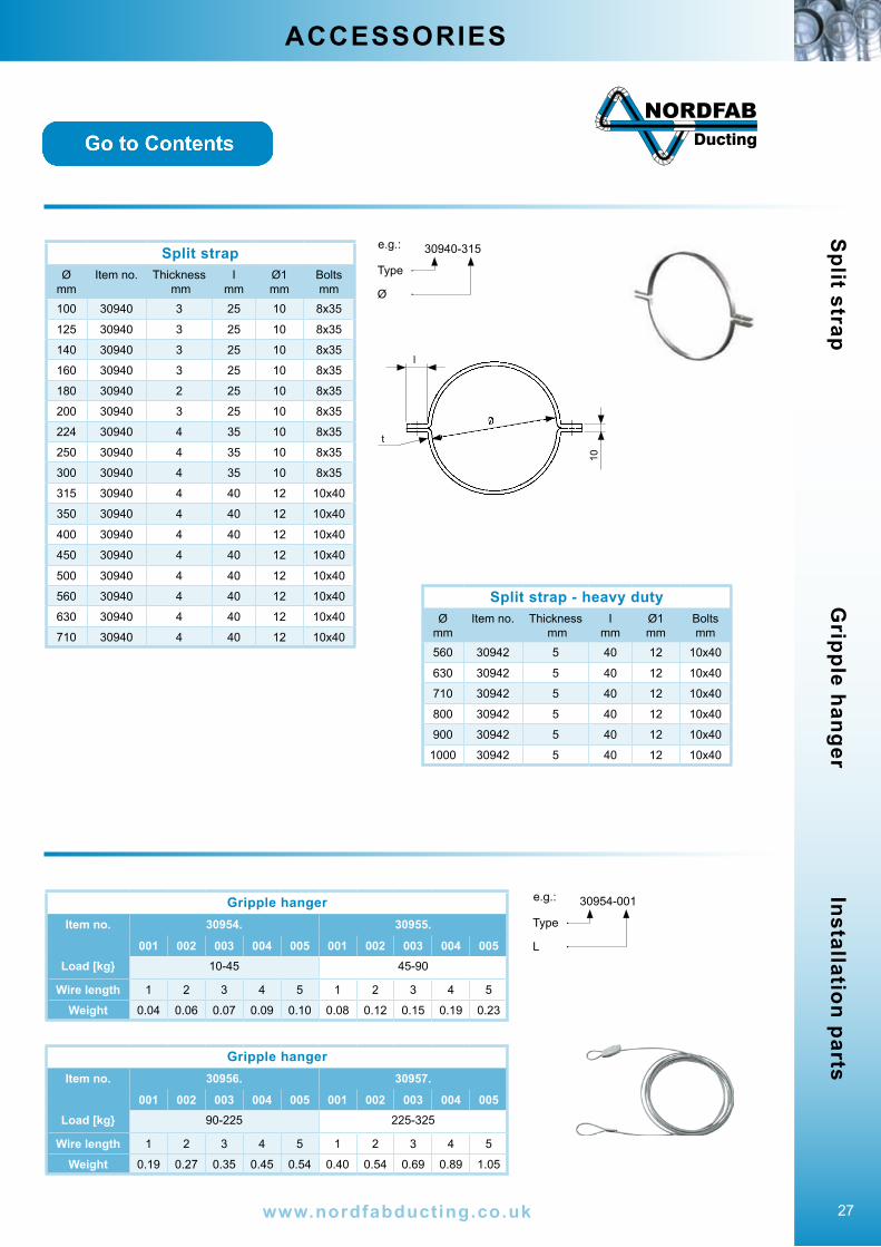
Split strapØ
mmItem no. Thickness
mmI
mmØ1 mm
Boltsmm
100 30940 3 25 10 8x35
125 30940 3 25 10 8x35
140 30940 3 25 10 8x35
160 30940 3 25 10 8x35
180 30940 2 25 10 8x35
200 30940 3 25 10 8x35
224 30940 4 35 10 8x35
250 30940 4 35 10 8x35
300 30940 4 35 10 8x35
315 30940 4 40 12 10x40
350 30940 4 40 12 10x40
400 30940 4 40 12 10x40
450 30940 4 40 12 10x40
500 30940 4 40 12 10x40
560 30940 4 40 12 10x40
630 30940 4 40 12 10x40
710 30940 4 40 12 10x40
t
l
10
Type
Ø
30940-315 e.g.:
ACCESSORIES S
plit strapInstallation parts
Type
L
30954-001 e.g.:
Gripple hanger
Gripple hangerItem no. 30954. 30955.
001 002 003 004 005 001 002 003 004 005Load [kg} 10-45 45-90
Wire length 1 2 3 4 5 1 2 3 4 5
Weight 0.04 0.06 0.07 0.09 0.10 0.08 0.12 0.15 0.19 0.23
Gripple hangerItem no. 30956. 30957.
001 002 003 004 005 001 002 003 004 005Load [kg} 90-225 225-325
Wire length 1 2 3 4 5 1 2 3 4 5
Weight 0.19 0.27 0.35 0.45 0.54 0.40 0.54 0.69 0.89 1.05
Split strap - heavy dutyØ
mmItem no. Thickness
mmI
mmØ1 mm
Boltsmm
560 30942 5 40 12 10x40
630 30942 5 40 12 10x40
710 30942 5 40 12 10x40
800 30942 5 40 12 10x40
900 30942 5 40 12 10x40
1000 30942 5 40 12 10x40
27www.nordfabducting.co.uk
THE WORLD’S FASTEST DUCTINGC l i p p e d D u c t i n g
Ducting
Nordfab DuctingLimewood Approach
Seacroft, LeedsLS14 1 NG
T: 01132 739 400F: 01132 650 735
www.nordfabducting.co.uk
&FLANGED DUCTWORK
Nordfab D
ucting Catalogue v4 11/[email protected]
Division of Dantherm Filtration Ltd.