Embed Size (px)
Citation preview
IOP PUBLISHING PHYSICS IN MEDICINE AND BIOLOGY
Phys. Med. Biol. 52 (2007) 6879–6892 doi:10.1088/0031-9155/52/23/007
Nonrigid registration with tissue-dependent filteringof the deformation field
Marius Staring, Stefan Klein and Josien P W Pluim
Image Sciences Institute, University Medical Center Utrecht, PO Box 85500, 3508 GA,Room Q0S.459, Utrecht, The Netherlands
E-mail: [email protected]
Received 4 May 2007, in final form 18 October 2007Published 8 November 2007Online at stacks.iop.org/PMB/52/6879
AbstractIn present-day medical practice it is often necessary to nonrigidly align imagedata. Current registration algorithms do not generally take the characteristicsof tissue into account. Consequently, rigid tissue, such as bone, can bedeformed elastically, growth of tumours may be concealed, and contrast-enhanced structures may be reduced in volume. We propose a method tolocally adapt the deformation field at structures that must be kept rigid, using atissue-dependent filtering technique. This adaptive filtering of the deformationfield results in locally linear transformations without scaling or shearing. Thedegree of filtering is related to tissue stiffness: more filtering is applied atstiff tissue locations, less at parts of the image containing nonrigid tissue.The tissue-dependent filter is incorporated in a commonly used registrationalgorithm, using mutual information as a similarity measure and cubic B-splinesto model the deformation field. The new registration algorithm is comparedwith this popular method. Evaluation of the proposed tissue-dependent filteringis performed on 3D computed tomography (CT) data of the thorax and on 2Ddigital subtraction angiography (DSA) images. The results show that tissue-dependent filtering of the deformation field leads to improved registrationresults: tumour volumes and vessel widths are preserved rather than affected.
1. Introduction
Nonrigid image registration is an important technique in the field of medical image processing(Hill et al 2001, Lester and Arridge 1999, Maintz and Viergever 1998). It performs the taskof finding the spatial correspondence between two images, i.e. it searches for a one-to-onemapping from voxels in one image to voxels in the other image. This mapping is calledthe transformation. Commonly, first a rigid or affine registration is performed to capturethe global transformation. The rigid or affine transformation is then used as a starting point
0031-9155/07/236879+14$30.00 © 2007 IOP Publishing Ltd Printed in the UK 6879

6880 M Staring et al
for a nonrigid registration, which searches for local deformations. An example of a popularnonrigid registration algorithm is that of Rueckert et al (1999).
A possible drawback of such a general nonrigid registration approach is that all tissue inthe image volume is treated nonrigidly. The rigidity or stiffness of different tissue types is nottaken into account. The implicit assumption that all tissue is deformable is violated in at leastthree situations.
(a) Truly rigid tissue. Bone tissue that is present in the image volume must not be allowedto deform. Treating the bones as deformable tissue can lead, for example, to undesiredthickening and bending of ribs (Staring et al 2005).
(b) Temporal changes of tissue. An example is the study of tumour progression in a patient. Asuccessful nonrigid registration will achieve a perfect fit between tumours of two differenttime points, effectively concealing tumour growth or shrinkage. To visualize the tumourgrowth with a difference image, the tumours have to be kept rigid.
(c) Intensity changes of tissue. Local intensity changes can be induced, for example, byinjection of a contrast agent. Rohlfing et al (2003) and Tanner et al (2000) demonstratethat contrast-enhanced breast lesions in MR are compressed after intensity-based nonrigidregistration. In Rohlfing and Maurer (2001) shrinkage is reported for contrast-enhancedvessels in CT digital subtraction angiography (CT-DSA).
In cases (b) and (c) the tissue is not truly, i.e. physically, rigid. However, in order to preventundesired volume changes of these structures, they should be regarded as undeformable.
Several methods are reported in the literature to address this issue. Some of thesemethods add a regularization or penalty term to the registration, thereby constraining thetransformation. Rohlfing et al (2003) achieve incompressibility by penalizing a deviation ofthe determinant of the Jacobian of the transformation from 1. The method does not distinguishbetween different tissue types, nor does it enforce rigidity of stiff tissue. Loeckx et al (2004)employ a rigidity penalty term to certain structures by penalizing a deviation of the Jacobianfrom orthonormality. Other ways to enforce rigidity of structures have also been presented.Tanner et al (2000) propose to couple the control points of a B-spline deformation to enforcerigidity on certain structures. It is assumed that the rotational part of the deformation can becaptured by the initial rigid registration. Another approach is taken by Little et al (1997),who constrain the nonlinear part of a deformation at rigid locations by multiplication with aweight function. Multiple rigid transformations are used by Arsigny et al (2005), each definedon different parts of the image, but influencing each other. Edwards et al (1998) model thedeformation field using a three-component deformation model, consisting of rigid, elasticand fluid structures. Brock et al (2005) have employed a finite element method to introducetissue-specific parameters. For the viscous fluid algorithm a locally adaptable regularizationtechnique is proposed that spatially varies the viscosity parameter (Lester et al 1999).
A structure is kept rigid during registration if and only if the underlying deformation fieldrepresents a locally rigid transformation. We propose to achieve rigidity of certain structuresby filtering the deformation field.
Filtering of deformation fields has been used in other situations, for example in opticalflow like registration algorithms. In these cases the filtering is typically used to regularizethe deformation field to get more plausible results. Thirion (1998) uses a Gaussian kernel tosmooth the deformation field. This kernel is not adapted to the underlying tissue type; it isfixed for the entire image volume. Cachier et al (1999) use the Demons algorithm, whichthey adapt with a filtering of the deformation field. They derive and employ a priori anda posteriori smoothing weights for the filtering; these weights vary over the image, but donot depend on the tissue type. Another method to smooth the deformation field is used by
Nonrigid registration with tissue-dependent filtering of the deformation field 6881
Stefanescu et al (2004). They regularize the deformation field by smoothing it with a Gaussiankernel with a standard deviation depending on the spatial position. They propose to take a largestandard deviation in areas where little deformation is expected (e.g., rigid areas), and viceversa. At boundaries of rigid and nonrigid tissue the deformation field within the rigid objectsis influenced by the nonrigid deformations of its surroundings. Both the extent and strengthof this influence are quite large, because a large standard deviation is used. Also, a scaling ofthe deformation field within rigid objects is not prevented with this method. Therefore, thatapproach is not suitable for the problem we address. To ensure rigidity of the deformationfield, an asymmetric kernel is needed with a large standard deviation inside the rigid objectand a small one outside.
The filter we propose has the property that undesired deformations at rigid structures areaddressed, while the surroundings are free to deform. The deformation field is adapted byfiltering the deformation field in a tissue-dependent way: the filter is different for each voxel,depending on the stiffness of the underlying tissue. In this way some parts of the image can bekept rigid, whereas other parts are allowed to deform freely. In section 2 the proposed tissue-dependent filter for regularizing the deformation field is described in detail. Incorporation ofthe filter in the registration algorithm is also described in that section.
For evaluation two applications are considered: the study of tumour progression in CTthorax imaging (an example of case (b)) and the study of the vasculature at several regions inthe human body in DSA imaging (an example of case (c)). The validation of the algorithm isdescribed in section 3, and the paper is concluded in section 4.
2. Method
Registration of a moving image IM(x) : �M ⊂ RD �→ R to a fixed image IF (x) : �F ⊂
RD �→ R, both of dimension D, is the problem of finding the deformation field d, or
equivalently the transformation T (x) = x + d(x), that spatially aligns IM(x + d(x)) andIF (x). Registration can be defined as a minimization problem:
d = arg mind
C [IF (x), IM(x + d(x))] , (1)
where C denotes a cost function and d the optimal solution.As discussed in the introduction, registration can result in a deformation field d(x) which
is nonrigid at rigid structures. The filter we propose filters the deformation field adaptively,based on the content of a ‘stiffness coefficient’ image c(x).
2.1. Filter design
For rigid tissue the corresponding part of the deformation field should be linear without scalingor shearing. Given the deformation field d, we achieve this by calculating a weighted meanm(x) of d over a neighbourhood Nx of x ∈ �F :
m(x) �∑x∈Nx
c(T (x))d(x)
/ ∑x∈Nx
c(T (x)), (2)
where c(x) is the stiffness coefficient image with values between 0 and 1. The stiffnesscoefficient image indicates, for each voxel, the relative stiffness of the underlying tissue.In case
∑x∈Nx
c(T (x)) = 0, we choose m(x) = d(x), to avoid division by zero. Inorder to control the degree of filtering, we define a filtered deformation field F(d(x)) byassigning a value close to the locally weighted mean deformation m(x) when the stiffness
6882 M Staring et al
coefficient c(x) is high, and a value close to the original deformation d(x) for low stiffnesscoefficients:
F(d(x)) � (1 − c(T (x)))d(x) + c(T (x))m(x). (3)
For neighbourhoods on the edge of rigid and nonrigid structures, the weighted mean m(x) isdetermined mainly by the voxels having a high stiffness coefficient. In other parts of the imageequation (2) yields an averaging, also in the nonrigid parts. By defining the tissue-dependentfiltering as in (3), it is controlled to what extent the weighted mean is used, such that it is onlyemployed at rigid parts of the image. The result is a more homogeneous, linear deformationfield at regions with a high c(x), where tissue is more stiff. At regions with a low c(x) thedeformation field is unaffected by the filtering, and therefore those regions can deform freely,as desired.
To obtain the stiffness coefficient image c(x) it is necessary to process the moving image,for example by segmenting the relevant structures and assigning a stiffness coefficient (a valuewithin [0, 1]) to the voxels. For CT images the Hounsfield units can be rescaled to values in[0, 1], since stiffer material usually implies a higher attenuation value. In this work we focuson the registration method, and therefore we have opted for a simple manual segmentation.
We are interested in the deformed moving image. Therefore, we only have to take carethat the transformation of that image, as found by the registration, obeys restrictions of rigidity.This means that only the relevant structures in the moving image have to be segmented.
The tissue-dependent filter F can be applied to the deformation field several times insuccession to increase the power of the filter. We define
Fk(d(x)) � F(Fk−1(d(x))), (4a)
F0(d(x)) � d(x). (4b)
When applying F multiple times (k > 1), the orientation and magnitude of the deformationfield in a neighbourhood become more similar. This effect is shown in figure 1.
The neighbourhood Nx in (2) is another parameter that can be controlled. It is chosento be a square in 2D and a cube in 3D, of size l × l and l × l × l voxels, respectively. Forlarge l the adaptive filter will linearize larger parts of the image at once, thereby increasing thepower of the filter. However, for large l, the deformation fields of two separate rigid structureslying close together might both be within the neighbourhood. This way, the deformationfield of both rigid structures evolves to the average of them, which is undesired. Therefore, asmall neighbourhood of l = 3 is used in this study. The power of the tissue-dependent filter iscontrolled with the number of successive applications k of the filter (see (4a)). In the followingsection a second parameter m is introduced, which also controls the power of the filter.
Figure 1(d) illustrates that the effect of the tissue-dependent filter is first observed nearthe boundary of rigid structures. After successive applications of the filter, the results arepropagated to the inside of such regions. Strong edges in the stiffness coefficient image atthe boundary of rigid and nonrigid tissue can result in sharp transitions in the deformationfield after filtering. Invertibility of the deformation field is not guaranteed. This can be easilyachieved by defining some rules on the displacement field (Stefanescu et al 2004). However,no problems were encountered in the experiments and therefore this step is omitted. Thetissue-dependent filter is based on a weighted mean, therefore, the filtered deformation fieldwill eventually, for large k, evolve to a translational field, not allowing rotations of rigidobjects.
The computational complexity of the tissue-dependent filter is linearly dependent onthe size of the neighbourhood lD , the number of voxels N in the image and the number ofsuccessive applications k : O(lDNk).
Nonrigid registration with tissue-dependent filtering of the deformation field 6883
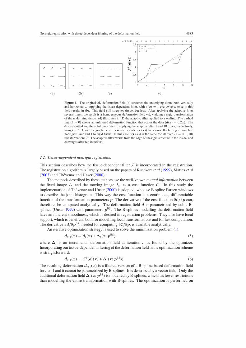
Figure 1. The original 2D deformation field (a) stretches the underlying tissue both verticallyand horizontally. Applying the tissue-dependent filter, with c(x) = 1 everywhere, once to thisfield results in (b). This field still stretches tissue, but less. After applying the adaptive filterseveral times, the result is a homogeneous deformation field (c), yielding a rigid transformationof the underlying tissue. (d) illustrates in 1D the adaptive filter applied to a scaling. The dashedline (k = 0) shows an unfiltered deformation function that scales the data (d(x) = 0.2x). Thedashed-dotted and the solid lines refer to applying the adaptive filter 1 and 10 times, respectively,using l = 5. Above the graph the stiffness coefficients c(T (x)) are shown: 0 referring to completenonrigid tissue and 1 to rigid tissue. In this case c(T (x)) is the same for all three (k = 0, 1, 10)
transformations T . The adaptive filter works from the edge of the rigid structure to the inside, andconverges after ten iterations.
2.2. Tissue-dependent nonrigid registration
This section describes how the tissue-dependent filter F is incorporated in the registration.The registration algorithm is largely based on the papers of Rueckert et al (1999), Mattes et al(2003) and Thevenaz and Unser (2000).
The methods described by these authors use the well-known mutual information betweenthe fixed image IF and the moving image IM as a cost function C. In this study theimplementation of Thevenaz and Unser (2000) is adopted, who use B-spline Parzen windowsto describe the joint histogram. This way the cost function is a continuous, differentiablefunction of the transformation parameters p. The derivative of the cost function ∂C/∂p can,therefore, be computed analytically. The deformation field d is parametrized by cubic B-splines (Unser 1999) with parameters pBS. The B-splines modelling the deformation fieldhave an inherent smoothness, which is desired in registration problems. They also have localsupport, which is beneficial both for modelling local transformations and for fast computation.The derivative ∂d/∂pBS, needed for computing ∂C/∂p, is available analytically.
An iterative optimization strategy is used to solve the minimization problem (1):
dt+1(x) = dt (x) + ∆t (x;pBS), (5)
where ∆t is an incremental deformation field at iteration t, as found by the optimizer.Incorporating our tissue-dependent filtering of the deformation field in the optimization schemeis straightforward:
dt+1(x) = Fk(dt (x) + ∆t (x;pBS)). (6)
The resulting deformation dt+1(x) is a filtered version of a B-spline based deformation fieldfor t > 1 and it cannot be parametrized by B-splines. It is described by a vector field. Only theadditional deformation field ∆t (x;pBS) is modelled by B-splines, which has fewer restrictionsthan modelling the entire transformation with B-splines. The optimization is performed on
6884 M Staring et al
∆t (x;pBS), i.e., on the B-spline coefficients only. This is computationally advantageouscompared to optimizing over the entire deformation field.
The tissue-dependent filtering does not necessarily have to be applied after everyoptimization iteration. To decrease the power of the filter it can be applied after every miterations. Summarizing, the proposed nonrigid registration is given by the following:
(i) perform m > 0 iterations of the optimizer, resulting in a new additional deformation field∆t (x;pBS);
(ii) calculate the deformation field dt+1(x) = dt (x) + ∆t (x;pBS);(iii) filter the deformation field, i.e., calculate dt+1(x) = Fk(dt+1(x)) according to
equations (2), (3) and (4a), (4b).
Repeat steps (i)–(iii) until convergence.A stochastic gradient descent optimizer is used to determine the additional deformation
field ∆t (x;pBS) in the following way: ∆t (x;pBS) = −at∂C/∂pBS, where at is the size ofthe step taken in the direction −∂C/∂pBS. The stochastic gradient descent optimizer usesan approximation of the derivative of the mutual information with respect to the B-splineparameterspBS. Approximation is done by using only a small random subset of voxelsfrom the fixed image. This has been shown to accelerate registration significantly, withoutcompromising registration accuracy (Klein et al 2007). At each iteration a step is takentowards the minimum of the cost function C. The size of this step at is determined by adecreasing function of the iteration number t. This function is of the form at = a/(t + A)α ,where a,A and α are user-defined constants. Following the suggestions in Spall (1998), inthis work A = 100.0 and α = 0.602 are used. The parameter a is related to the expectedmagnitude of the deformation, and is tuned for each application. As a stopping condition auser-defined number of iterations is used, upon which convergence is assumed. In order toavoid local minima, a multiresolution approach is taken. A Gaussian image pyramid is usedwith a subsampling factor of 2. Also a multigrid approach is taken: when the image resolutionis doubled, the B-spline control point spacing is halved. Prior to the nonrigid registration anaffine registration is performed in order to capture the global transformation between the fixedand the moving image.
3. Experiments and results
In order to evaluate the effectiveness of the proposed tissue-dependent nonrigid registration,it is compared with a general nonrigid registration approach based only on B-splines. Thisgeneral approach does not apply the tissue-dependent filtering of the deformation field, butis similar to the proposed algorithm in all other respects (see the description in section 2.2).The methods will be referred to as ‘BS’ (B-spline only based) and ‘BSF’ (B-splines withtissue-dependent filtering of the deformation field).
The two methods are illustrated on a synthetic example (section 3.1), and compared onclinical data, namely 3D CT follow-up data of the thorax containing lung tumours (section 3.2)and 2D digital subtraction angiography (DSA) image data, see section 3.3. The applicationsare examples of cases (b) and (c) of the list given in the introduction. Both applicationsconsider structures that are not physically rigid, but to prevent undesired volume changes,they should be regarded as undeformable. Special attention is given to the influence of theparameters k and m.
In all experiments with BSF, the size of the neighbourhood Nx in equation (2) is 3 ×3 voxels in 2D and 3 × 3 × 3 in 3D. For both BS and BSF, the number of bins for thecalculation of the mutual information was set to 32. All experiments were performed with
Nonrigid registration with tissue-dependent filtering of the deformation field 6885
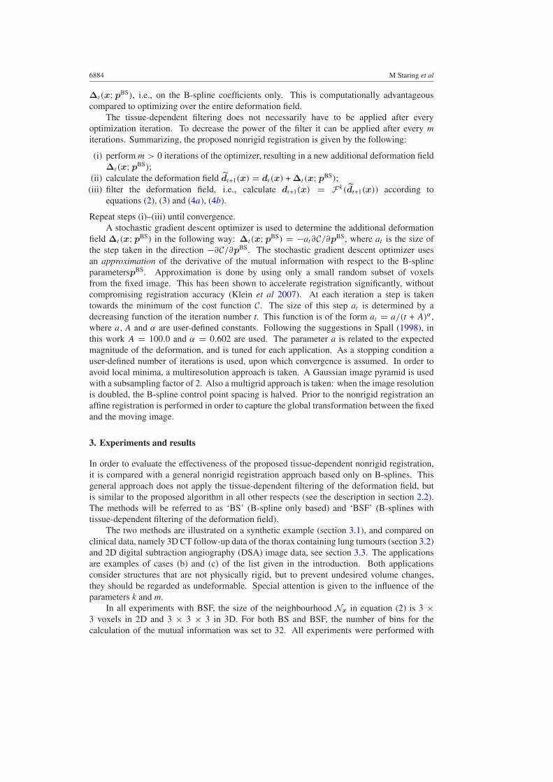
Figure 2. BS registration compared with the adaptive filtering of the deformation field. (a) Thefixed image IF , (b) the moving image IM , (c) the result with BS and (d) the result with BSF(k = 1,m = 100, l = 3). When the neighbourhood size is increased to l = 5, or when morefiltering is applied (m = 10), the resulting images are equal to the fixed image. In (e) a profile inthe horizontal direction of the x-component of the deformation field is depicted. In the legend theparameters (k, l, m) refer to the corresponding BSF registration. The two vertical lines indicatethe rigid part.
software developed by the authors (www.isi.uu.nl/Elastix). This registration package is largelybased on the Insight Segmentation and Registration Toolkit (Ibanez et al 2005). Filtering thedeformation field took approximately 1 s. and 1.7 s. for k = 1 and k = 10, respectively, on2D 5122 data. For 3D 2563 data this took 140 and 275 s. approximately. An AMD Opteron2218 running at 2.6 GHz. was used, without multi-threading enabled.
3.1. 2D Synthetic example
A 2D synthetic example image was constructed to demonstrate the behaviour of the nonrigidregistration algorithm with and without tissue-dependent filtering. Figures 2(a) and (b) showthe fixed and moving images, respectively, both of size 128 × 128 pixels. The central whitestructure represents a rigid structure, for which the stiffness coefficient image c(x) was setto 1.0. The two larger white structures represent some nonrigid image content, for whichc(x) = 0.0. A standard nonrigid registration was performed using three resolutions. At eachresolution 350 iterations of the optimizer were used. A multigrid approach was taken, witha B-spline grid spacing at the final resolution of 64 pixels. No affine or rigid registrationwas performed prior to nonrigid registration. The result of the registration is shown infigure 2(c). It is clear that the rigid inner structure has thickened. The B-spline fails to keepthe inner rigid structure rigid, because the control points are pulled apart by the contractionof the two outer white structures. The experiment is repeated with BSF with low filteringpower (k = 1, l = 3,m = 100), resulting in a still thickened inner structure (see figure 2(d)).The power is increased by applying the filter more often (m = 10), and by extending theneighbourhood size to l = 5. Both approaches result in a perfect registration. In figure 2(e) ahorizontal profile through the inner rigid structure of the x-component of the deformation fieldis shown for the three BSF versions. BSF (1, 100, 3) still thickens the inner structure, whilethe other two show no displacement at the centre.
3.2. 3D CT thorax data with lung tumours
Nonrigid registration is a valuable tool for following disease progress of patients over time.A possible way to detect changes is by analysing the deformation field found by the nonrigidregistration, as is done by Rey et al (2002). Another way to evaluate this progress isto visually inspect the difference between a first scan, taken at time t0, and a registered
6886 M Staring et al
(a) (b) (c)
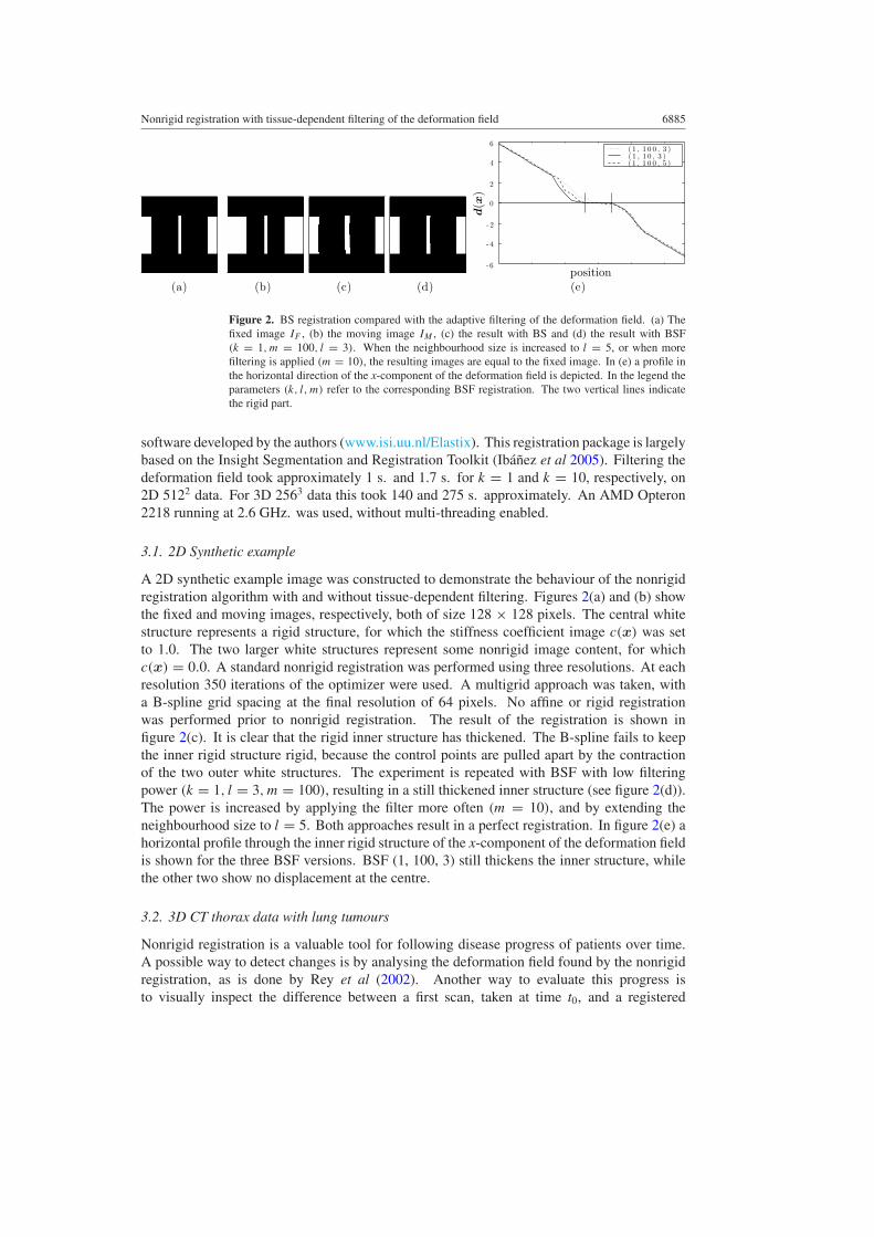
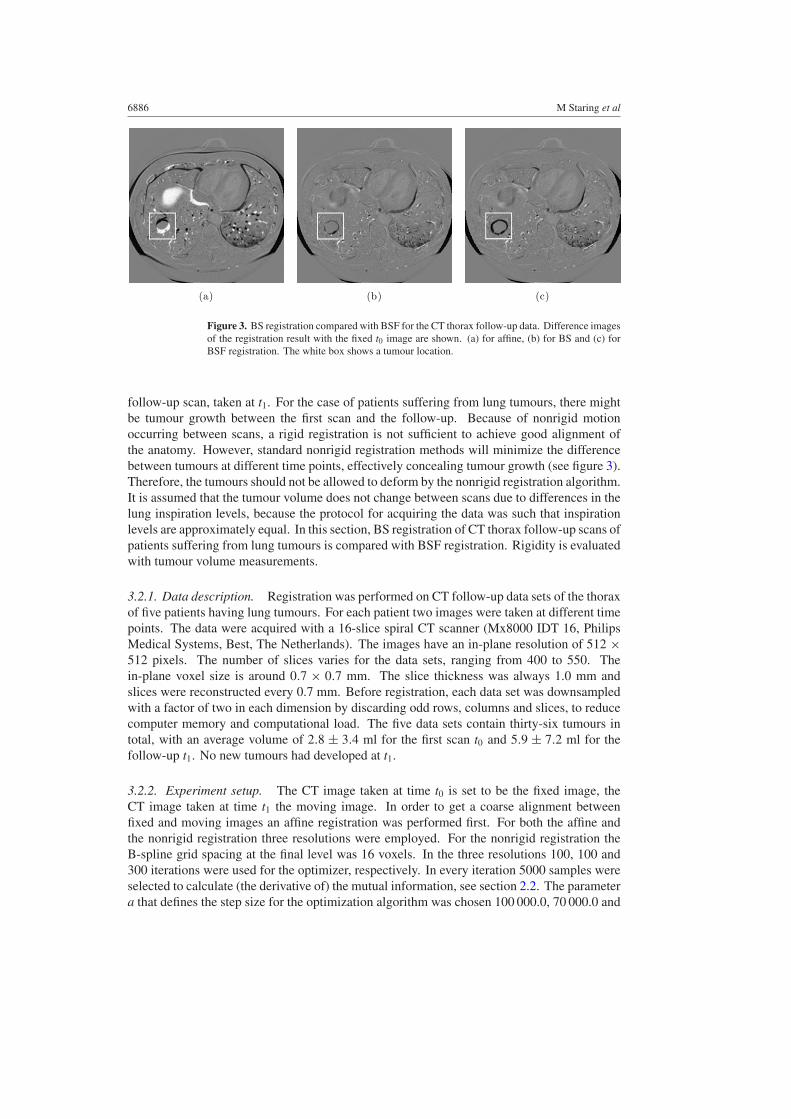
Figure 3. BS registration compared with BSF for the CT thorax follow-up data. Difference imagesof the registration result with the fixed t0 image are shown. (a) for affine, (b) for BS and (c) forBSF registration. The white box shows a tumour location.
follow-up scan, taken at t1. For the case of patients suffering from lung tumours, there mightbe tumour growth between the first scan and the follow-up. Because of nonrigid motionoccurring between scans, a rigid registration is not sufficient to achieve good alignment ofthe anatomy. However, standard nonrigid registration methods will minimize the differencebetween tumours at different time points, effectively concealing tumour growth (see figure 3).Therefore, the tumours should not be allowed to deform by the nonrigid registration algorithm.It is assumed that the tumour volume does not change between scans due to differences in thelung inspiration levels, because the protocol for acquiring the data was such that inspirationlevels are approximately equal. In this section, BS registration of CT thorax follow-up scans ofpatients suffering from lung tumours is compared with BSF registration. Rigidity is evaluatedwith tumour volume measurements.
3.2.1. Data description. Registration was performed on CT follow-up data sets of the thoraxof five patients having lung tumours. For each patient two images were taken at different timepoints. The data were acquired with a 16-slice spiral CT scanner (Mx8000 IDT 16, PhilipsMedical Systems, Best, The Netherlands). The images have an in-plane resolution of 512 ×512 pixels. The number of slices varies for the data sets, ranging from 400 to 550. Thein-plane voxel size is around 0.7 × 0.7 mm. The slice thickness was always 1.0 mm andslices were reconstructed every 0.7 mm. Before registration, each data set was downsampledwith a factor of two in each dimension by discarding odd rows, columns and slices, to reducecomputer memory and computational load. The five data sets contain thirty-six tumours intotal, with an average volume of 2.8 ± 3.4 ml for the first scan t0 and 5.9 ± 7.2 ml for thefollow-up t1. No new tumours had developed at t1.
3.2.2. Experiment setup. The CT image taken at time t0 is set to be the fixed image, theCT image taken at time t1 the moving image. In order to get a coarse alignment betweenfixed and moving images an affine registration was performed first. For both the affine andthe nonrigid registration three resolutions were employed. For the nonrigid registration theB-spline grid spacing at the final level was 16 voxels. In the three resolutions 100, 100 and300 iterations were used for the optimizer, respectively. In every iteration 5000 samples wereselected to calculate (the derivative of) the mutual information, see section 2.2. The parametera that defines the step size for the optimization algorithm was chosen 100 000.0, 70 000.0 and
Nonrigid registration with tissue-dependent filtering of the deformation field 6887
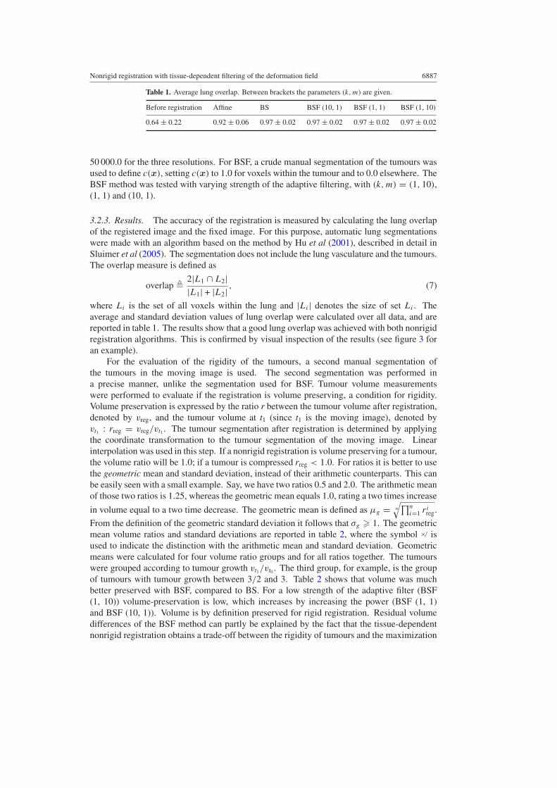
Table 1. Average lung overlap. Between brackets the parameters (k, m) are given.
Before registration Affine BS BSF (10, 1) BSF (1, 1) BSF (1, 10)
0.64 ± 0.22 0.92 ± 0.06 0.97 ± 0.02 0.97 ± 0.02 0.97 ± 0.02 0.97 ± 0.02
50 000.0 for the three resolutions. For BSF, a crude manual segmentation of the tumours wasused to define c(x), setting c(x) to 1.0 for voxels within the tumour and to 0.0 elsewhere. TheBSF method was tested with varying strength of the adaptive filtering, with (k,m) = (1, 10),(1, 1) and (10, 1).
3.2.3. Results. The accuracy of the registration is measured by calculating the lung overlapof the registered image and the fixed image. For this purpose, automatic lung segmentationswere made with an algorithm based on the method by Hu et al (2001), described in detail inSluimer et al (2005). The segmentation does not include the lung vasculature and the tumours.The overlap measure is defined as
overlap � 2|L1 ∩ L2||L1| + |L2| , (7)
where Li is the set of all voxels within the lung and |Li | denotes the size of set Li . Theaverage and standard deviation values of lung overlap were calculated over all data, and arereported in table 1. The results show that a good lung overlap was achieved with both nonrigidregistration algorithms. This is confirmed by visual inspection of the results (see figure 3 foran example).
For the evaluation of the rigidity of the tumours, a second manual segmentation ofthe tumours in the moving image is used. The second segmentation was performed ina precise manner, unlike the segmentation used for BSF. Tumour volume measurementswere performed to evaluate if the registration is volume preserving, a condition for rigidity.Volume preservation is expressed by the ratio r between the tumour volume after registration,denoted by vreg, and the tumour volume at t1 (since t1 is the moving image), denoted byvt1 : rreg = vreg/vt1 . The tumour segmentation after registration is determined by applyingthe coordinate transformation to the tumour segmentation of the moving image. Linearinterpolation was used in this step. If a nonrigid registration is volume preserving for a tumour,the volume ratio will be 1.0; if a tumour is compressed rreg < 1.0. For ratios it is better to usethe geometric mean and standard deviation, instead of their arithmetic counterparts. This canbe easily seen with a small example. Say, we have two ratios 0.5 and 2.0. The arithmetic meanof those two ratios is 1.25, whereas the geometric mean equals 1.0, rating a two times increase
in volume equal to a two time decrease. The geometric mean is defined as µg = n
√∏ni=1 ri
reg.
From the definition of the geometric standard deviation it follows that σg � 1. The geometricmean volume ratios and standard deviations are reported in table 2, where the symbol ×/ isused to indicate the distinction with the arithmetic mean and standard deviation. Geometricmeans were calculated for four volume ratio groups and for all ratios together. The tumourswere grouped according to tumour growth vt1/vt0 . The third group, for example, is the groupof tumours with tumour growth between 3/2 and 3. Table 2 shows that volume was muchbetter preserved with BSF, compared to BS. For a low strength of the adaptive filter (BSF(1, 10)) volume-preservation is low, which increases by increasing the power (BSF (1, 1)and BSF (10, 1)). Volume is by definition preserved for rigid registration. Residual volumedifferences of the BSF method can partly be explained by the fact that the tissue-dependentnonrigid registration obtains a trade-off between the rigidity of tumours and the maximization
6888 M Staring et al
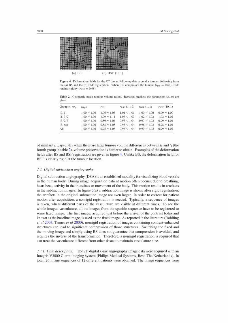
(a) BS (b) BSF (10,1)
Figure 4. Deformation fields for the CT thorax follow-up data around a tumour, following fromthe (a) BS and the (b) BSF registration. Where BS compresses the tumour (rBS = 0.69), BSFretains rigidity (rBSF = 0.98).
Table 2. Geometric mean tumour volume ratios. Between brackets the parameters (k, m) aregiven.
Group vt1 /vt0 rrigid rBS rBSF (1, 10) rBSF (1, 1) rBSF (10, 1)
(0, 1] 1.00 ×/ 1.00 1.06 ×/ 1.03 1.01 ×/ 1.01 1.00 ×/ 1.00 0.99 ×/ 1.00(1, 3/2] 1.00 ×/ 1.00 1.09 ×/ 1.11 1.03 ×/ 1.03 1.02 ×/ 1.02 1.02 ×/ 1.02(3/2, 3] 1.00 ×/ 1.00 0.89 ×/ 1.04 0.93 ×/ 1.04 0.97 ×/ 1.02 0.99 ×/ 1.01(3, ∞) 1.00 ×/ 1.00 0.88 ×/ 1.05 0.93 ×/ 1.04 0.96 ×/ 1.02 0.98 ×/ 1.01All 1.00 ×/ 1.00 0.95 ×/ 1.08 0.96 ×/ 1.04 0.99 ×/ 1.02 0.99 ×/ 1.02
of similarity. Especially when there are large tumour volume differences between t0 and t1 (thefourth group in table 2), volume preservation is harder to obtain. Examples of the deformationfields after BS and BSF registration are given in figure 4. Unlike BS, the deformation field forBSF is clearly rigid at the tumour location.
3.3. Digital subtraction angiography
Digital subtraction angiography (DSA) is an established modality for visualizing blood vesselsin the human body. During image acquisition patient motion often occurs, due to breathing,heart beat, activity in the intestines or movement of the body. This motion results in artefactsin the subtraction images. In figure 5(a) a subtraction image is shown after rigid registration;the artefacts in the original subtraction image are even larger. In order to correct for patientmotion after acquisition, a nonrigid registration is needed. Typically, a sequence of imagesis taken, where different parts of the vasculature are visible at different times. To see thewhole imaged vasculature, all the images from the specific sequence have to be registered tosome fixed image. The first image, acquired just before the arrival of the contrast bolus andknown as the baseline image, is used as the fixed image. As reported in the literature (Rohlfinget al 2003, Tanner et al 2000), nonrigid registration of images containing contrast-enhancedstructures can lead to significant compression of those structures. Switching the fixed andthe moving image and simply using BS does not guarantee that compression is avoided, andrequires the inverse of the transformation. Therefore, a nonrigid registration is required thatcan treat the vasculature different from other tissue to maintain vasculature size.
3.3.1. Data description. The 2D digital x-ray angiography image data were acquired with anIntegris V3000 C-arm imaging system (Philips Medical Systems, Best, The Netherlands). Intotal, 26 image sequences of 12 different patients were obtained. The image sequences were
Nonrigid registration with tissue-dependent filtering of the deformation field 6889
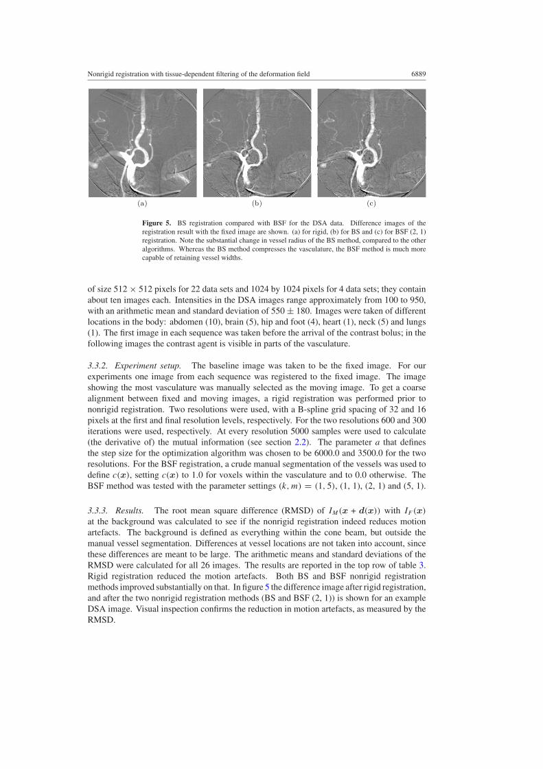
(a) (b) (c)
Figure 5. BS registration compared with BSF for the DSA data. Difference images of theregistration result with the fixed image are shown. (a) for rigid, (b) for BS and (c) for BSF (2, 1)registration. Note the substantial change in vessel radius of the BS method, compared to the otheralgorithms. Whereas the BS method compresses the vasculature, the BSF method is much morecapable of retaining vessel widths.
of size 512 × 512 pixels for 22 data sets and 1024 by 1024 pixels for 4 data sets; they containabout ten images each. Intensities in the DSA images range approximately from 100 to 950,with an arithmetic mean and standard deviation of 550 ± 180. Images were taken of differentlocations in the body: abdomen (10), brain (5), hip and foot (4), heart (1), neck (5) and lungs(1). The first image in each sequence was taken before the arrival of the contrast bolus; in thefollowing images the contrast agent is visible in parts of the vasculature.
3.3.2. Experiment setup. The baseline image was taken to be the fixed image. For ourexperiments one image from each sequence was registered to the fixed image. The imageshowing the most vasculature was manually selected as the moving image. To get a coarsealignment between fixed and moving images, a rigid registration was performed prior tononrigid registration. Two resolutions were used, with a B-spline grid spacing of 32 and 16pixels at the first and final resolution levels, respectively. For the two resolutions 600 and 300iterations were used, respectively. At every resolution 5000 samples were used to calculate(the derivative of) the mutual information (see section 2.2). The parameter a that definesthe step size for the optimization algorithm was chosen to be 6000.0 and 3500.0 for the tworesolutions. For the BSF registration, a crude manual segmentation of the vessels was used todefine c(x), setting c(x) to 1.0 for voxels within the vasculature and to 0.0 otherwise. TheBSF method was tested with the parameter settings (k,m) = (1, 5), (1, 1), (2, 1) and (5, 1).
3.3.3. Results. The root mean square difference (RMSD) of IM(x + d(x)) with IF (x)
at the background was calculated to see if the nonrigid registration indeed reduces motionartefacts. The background is defined as everything within the cone beam, but outside themanual vessel segmentation. Differences at vessel locations are not taken into account, sincethese differences are meant to be large. The arithmetic means and standard deviations of theRMSD were calculated for all 26 images. The results are reported in the top row of table 3.Rigid registration reduced the motion artefacts. Both BS and BSF nonrigid registrationmethods improved substantially on that. In figure 5 the difference image after rigid registration,and after the two nonrigid registration methods (BS and BSF (2, 1)) is shown for an exampleDSA image. Visual inspection confirms the reduction in motion artefacts, as measured by theRMSD.
6890 M Staring et al
- 1 0 - 8 - 6 - 4 - 2 0 2
Dr i g id , n o r e g
DB S , r i g id
DB S F , r i g id
DB S F ,B S
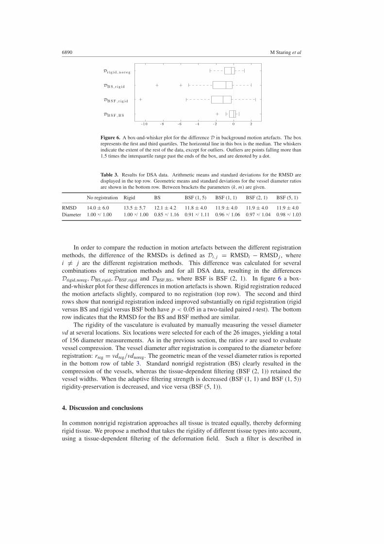
Figure 6. A box-and-whisker plot for the difference D in background motion artefacts. The boxrepresents the first and third quartiles. The horizontal line in this box is the median. The whiskersindicate the extent of the rest of the data, except for outliers. Outliers are points falling more than1.5 times the interquartile range past the ends of the box, and are denoted by a dot.
Table 3. Results for DSA data. Arithmetic means and standard deviations for the RMSD aredisplayed in the top row. Geometric means and standard deviations for the vessel diameter ratiosare shown in the bottom row. Between brackets the parameters (k, m) are given.
No registration Rigid BS BSF (1, 5) BSF (1, 1) BSF (2, 1) BSF (5, 1)
RMSD 14.0 ± 6.0 13.5 ± 5.7 12.1 ± 4.2 11.8 ± 4.0 11.9 ± 4.0 11.9 ± 4.0 11.9 ± 4.0Diameter 1.00 ×/ 1.00 1.00 ×/ 1.00 0.85 ×/ 1.16 0.91 ×/ 1.11 0.96 ×/ 1.06 0.97 ×/ 1.04 0.98 ×/ 1.03
In order to compare the reduction in motion artefacts between the different registrationmethods, the difference of the RMSDs is defined as Di,j = RMSDi − RMSDj , wherei �= j are the different registration methods. This difference was calculated for severalcombinations of registration methods and for all DSA data, resulting in the differencesDrigid,noreg,DBS,rigid,DBSF,rigid and DBSF,BS, where BSF is BSF (2, 1). In figure 6 a box-and-whisker plot for these differences in motion artefacts is shown. Rigid registration reducedthe motion artefacts slightly, compared to no registration (top row). The second and thirdrows show that nonrigid registration indeed improved substantially on rigid registration (rigidversus BS and rigid versus BSF both have p < 0.05 in a two-tailed paired t-test). The bottomrow indicates that the RMSD for the BS and BSF method are similar.
The rigidity of the vasculature is evaluated by manually measuring the vessel diametervd at several locations. Six locations were selected for each of the 26 images, yielding a totalof 156 diameter measurements. As in the previous section, the ratios r are used to evaluatevessel compression. The vessel diameter after registration is compared to the diameter beforeregistration: rreg = vdreg/vdnoreg. The geometric mean of the vessel diameter ratios is reportedin the bottom row of table 3. Standard nonrigid registration (BS) clearly resulted in thecompression of the vessels, whereas the tissue-dependent filtering (BSF (2, 1)) retained thevessel widths. When the adaptive filtering strength is decreased (BSF (1, 1) and BSF (1, 5))rigidity-preservation is decreased, and vice versa (BSF (5, 1)).
4. Discussion and conclusions
In common nonrigid registration approaches all tissue is treated equally, thereby deformingrigid tissue. We propose a method that takes the rigidity of different tissue types into account,using a tissue-dependent filtering of the deformation field. Such a filter is described in
Nonrigid registration with tissue-dependent filtering of the deformation field 6891
this work, and incorporated in a nonrigid registration framework: tissue-dependent nonrigidregistration.
In contrast to other work on filtering of the deformation field, we designed the filterspecifically to maintain the rigidity of tissue. All other work we are aware of uses filteringto obtain smoothness of the deformation, sometimes also in a tissue-dependent manner. Theproposed filter does not affect the deformation field outside the region that is to be kept rigid,thereby allowing the neighbouring tissue of the rigid structures to deform freely. Methodsthat add a penalty term to the cost function to achieve rigidity need to weigh the penalty termagainst similarity. The choice of this weight is somewhat nonintuitive and a matter of tuning.Varying the strength of the proposed tissue-dependent filtering can be done with two intuitiveparameters (k and m). The results show that by increasing k and/or decreasing m the methodis better capable of retaining rigidity, and vice versa. For very large k the deformation fieldwill converge to a translational field. The proposed method also offers possibilities to moverigid objects that are in close proximity, independently of each other by adding an object labelto the filtering process.
A segmentation of the rigid structures is needed to define which regions are to be keptrigid. In this work we used rough manual segmentations, which is labour intensive, andtherefore not very practical in a clinical setting. Since a rough segmentation is sufficient, a(semi-) automatic segmentation method will usually be available.
The proposed tissue-dependent nonrigid registration was evaluated on CT thorax follow-up data and Digital Subtraction Angiography (DSA) data. It was compared against a standardB-spline based registration approach. From the experiments on the CT thorax follow-up data itis observed that tissue-dependent nonrigid registration is better in terms of preserving tumourvolume than a standard B-spline based approach. The DSA data show a clear improvementof the proposed method over the B-spline method in retaining vessel widths.
Based on the results and on visual inspection of the data, it is concluded that the tissue-dependent nonrigid registration algorithm is indeed able to model locally rigid transformations,thereby improving registration results.
Acknowledgments
This research was funded by the Netherlands Organisation for Scientific Research (NWO).This work also benefited from the use of the Insight Segmentation and Registration Toolkit(ITK), an open source software package developed as an initiative of the US National Libraryof Medicine and available at http://www.itk.org.
References
Arsigny V, Pennec X and Ayache N 2005 Polyrigid and polyaffine transformations: a novel geometrical tool to dealwith non-rigid deformations application to the registration of histological slices Med. Image Anal. 9 507–23
Brock K K, Sharpe M B, Dawson L A, Kim S M and Jaffray D A 2005 Accuracy of finite element model-basedmulti-organ deformable image registration Med. Phys. 32 1647–59
Cachier P, Pennec X and Ayache N 1999 Fast non-rigid matching by gradient descent: study and improvements ofthe demons algorithm Research Report 3706, INRIA
Edwards P J, Hill D L G, Little J A and Hawkes D J 1998 A three-component deformation model for image-guidedsurgery Med. Image Anal. 2 355–67
Hill D L G, Batchelor P G, Holden M and Hawkes D J 2001 Medical image registration Phys. Med. Biol. 46 R1–45Hu S, Hoffman E A and Reinhardt J M 2001 Automatic lung segmentation for accurate quantitation of volumetric
X-ray CT images IEEE Trans. Med. Imaging 20 490–8Ibanez L, Schroeder W, Ng L and Cates J 2005 The ITK Software Guide 2nd edn (New York: Kitware, Inc.) (ISBN
1-930934-15-7)
6892 M Staring et al
Klein S, Staring M and Pluim J P W 2007 Evaluation of optimisation methods for nonrigid medical image registrationusing mutual information and B-splines IEEE Trans. Image Process. 16 at press
Lester H and Arridge S R 1999 A survey of hierarchical non-linear medical image registration Pattern Recogn.32 129–49
Lester H, Arridge S R, Jansons K M, Lemieux L, Hajnal J V and Oatridge A 1999 Non-linear registration with thevariable viscosity fluid algorithm IPMI (Lect. Notes Comput. Sci. vol 1613) (Berlin: Springer) pp 238–51
Little J A, G. Hill D L and Hawkes D J 1997 Deformations incorporating rigid structures Comput. Vis. ImageUnderstand. 66 223–32
Loeckx D, Maes F, Vandermeulen D and Suetens P 2004 Nonrigid image registration using free-form deformationswith a local rigidity constraint MICCAI (Lect. Notes Comput. Sci. vol 3216) pp 639–46
Maintz J B A and Viergever M A 1998 A survey of medical image registration Med. Image Anal. 2 1–36Mattes D, Haynor D R, Vesselle H, Lewellen T K and Eubank W 2003 PET-CT image registration in the chest using
free-form deformations IEEE Trans. Med. Imaging 22 120–8Rey D, Subsol G, Delingette H and Ayache N 2002 Automatic detection and segmentation of evolving processes in
3D medical images: Application to multiple sclerosis Med. Image Anal. 6 163–79Rohlfing T and Maurer C R Jr 2001 Intensity-based nonrigid registration using adaptive multilevel free-form
deformation with an incompressibility constraint MICCAI (Lect. Notes Comput. Sci. vol 2208) pp 111–9Rohlfing T, Maurer C R Jr, Bluemke D A and Jacobs M A 2003 Volume-preserving nonrigid registration of MR breast
images using free-form deformation with an incompressibility constraint IEEE Trans. Med. Imaging 22 730–41Rueckert D, Sonoda L I, Hayes C, Hill D L G, Leach M O and Hawkes D J 1999 Nonrigid registration using free-form
deformations: application to breast MR images IEEE Trans. Med. Imaging 18 712–21Sluimer I C, Prokop M and van Ginneken B 2005 Towards automated segmentation of the pathological lung in CT
IEEE Trans. Med. Imaging 24 1025–38Spall J C 1998 Implementation of the simultaneous perturbation method for stochastic optimization IEEE Trans.
Aerosp. Electron. Syst. 34 817–23Staring M, Klein S and Pluim J P W 2005 Nonrigid registration with adaptive, content-based filtering of the deformation
field SPIE Medical Imaging: Image Processing (Proceedings of SPIE vol 5747) (Bellingham, WA: SPIE OpticalEngineering Press) pp 212–21
Stefanescu R, Pennec X and Ayache N 2004 Grid powered nonlinear image registration with locally adaptiveregularization Med. Image Anal. 8 325–42
Tanner C, Schnabel J A, Chung D, Clarkson M J, Rueckert D, Hill D L G and Hawkes D J 2000 Volume and shapepreservation of enhancing lesions when applying nonrigid registration to a time series of contrast enhancingMR breast images MICCAI (Lect. Notes Comput. Sci. vol 1935) pp 327–37
Thevenaz P and Unser M 2000 Optimization of mutual information for multiresolution image registration IEEE Trans.Image Process. 9 2083–99
Thirion J P 1998 Image matching as a diffusion process: an analogy with Maxwell’s demons Med. Image Anal.2 243–60
Unser M 1999 Splines: a perfect fit for signal and image processing IEEE Signal Process. Mag. 16 22–38