Embed Size (px)
Citation preview
Ensuring reservoir safety into the future. Thomas Telford, London, 2008
Nonlinear seismic assessment of lightly reinforced concrete
intake towers
R. SABATINO, Lloyd’s Register, London, UK (formerly KBR Ltd)
A.J. CREWE, University of Bristol, UK
W.E. DANIELL, University of Bristol, UK
C.A. TAYLOR, University of Bristol, UK
SYNOPSIS. Published guidance on the seismic analysis of reinforced
concrete intake/outlet towers is limited, especially for their nonlinear
response, due to limited knowledge on the nonlinear characteristics of
existing and new towers. Proving the integrity of existing towers is an
international problem for dam owners, and an industrial need exists for a
rational, cost-effective and validated method for their assessment.
This paper describes a series of tests aimed at investigating the seismic
performance of typically reinforced, non-seismically designed towers.
Monotonic and cyclic push-over tests were performed on 1/6th
scaled
models. The results from the physical tests were used to validate a 3D
nonlinear finite element model of the towers, using embedded steel
reinforcement and a smeared crack model to simulate crack properties of the
concrete material. The dynamic performance of the structures was
investigated by developing a simplified single degree of freedom model and
performing a number of simulations to obtain fragility curves of the system.
This simplified model was capable of simulating the degrading, hysteretic
properties of the towers and was used to perform nonlinear time history
analyses using a range of parameters. A probabilistic approach was selected
as the basis of the performance evaluation process using fragility analyses as
a tool for modelling the uncertainty associated with the parameter selection.
Based on the experimental and analytical results, a three-staged assessment
procedure for the seismic performance assessment of the towers was
proposed.
INTRODUCTION
Intake/outlet facilities (Figure 1) form part of the vital infrastructure of a
dam as they regulate the outflow of water from the impounded reservoir. In
the event of an earthquake occurring, it is therefore essential that any
damage to the intake tower does not induce the catastrophic failure of the

ENSURING RESERVOIR SAFETY
dam, and consequent release of water. Continued operation of the facility
may also be required to allow controlled release of water to permit essential
repair work to be carried out if damage occurred to the main barrage itself.
The seismic risk to dams in the UK has been studied extensively, resulting
in the publication of design guides (Charles et al., 1991; Institution of Civil
Engineers, 1998). However, limited guidance is available for specifically
assessing the seismic vulnerability of intake towers (ICOLD, 2002; USACE,
2003). Existing seismic design codes, such as Eurocode 8 (BSI, 2004)
provide limited guidance for their application to intake towers.
The purpose of this research was to determine the characteristic nonlinear
behaviour of typical UK lightly reinforced concrete intake towers under
seismic loading. This was done through a series of experimental and
theoretical investigations into the nonlinear behaviour of scaled intake tower
models subject to monotonic and cyclic pushover loads, leading to the
development of a simplified probabilistic tool as part of a rational method
for the evaluation of their seismic performance. By establishing appropriate
performance requirements for given limit states, the seismic response of the
towers was evaluated in a probabilistic context.
Figure 1: View of Errochty tower and access bridge
EXPERIMENTAL MODELLING OF INTAKE TOWERS
A desk study of the typical characteristics of existing reinforced concrete
intake towers in reservoirs in the United Kingdom was undertaken. By
averaging the typical values for geometry, reinforcement steel and material
properties, a prototype tower configuration was obtained. For the purpose of
this project, a rectangular hollow free-standing tower was selected. The area
of reinforcement steel to area of concrete ratio (ρ) was chosen as 0.25% for
both vertical (longitudinal) and horizontal (secondary) reinforcement,
representing typical UK values. The control house, access bridge and other
appendages, as well as the water-structure and soil-structure effects, were
SABATINO, CREWE, DANIELL & TAYLOR
not considered as the primary purpose of the experimental programme was
the understanding of the structural response to earthquake type loading only.
Table 1 summarises the prototype and scaled model geometrical properties.
The choice of the 1:6 scale was based on a compromise between practical
size for testing, cost and the ability of adequately replicating the failure
behaviour of the intake tower.
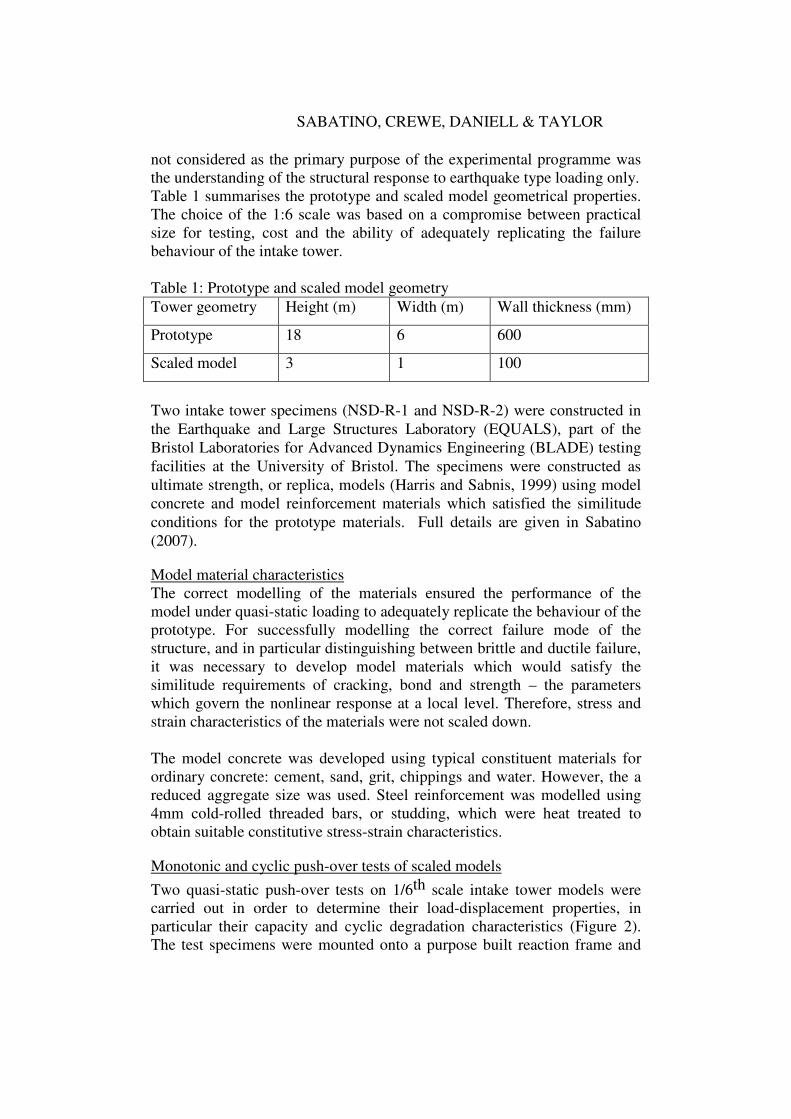
Table 1: Prototype and scaled model geometry
Tower geometry Height (m) Width (m) Wall thickness (mm)
Prototype 18 6 600
Scaled model 3 1 100
Two intake tower specimens (NSD-R-1 and NSD-R-2) were constructed in
the Earthquake and Large Structures Laboratory (EQUALS), part of the
Bristol Laboratories for Advanced Dynamics Engineering (BLADE) testing
facilities at the University of Bristol. The specimens were constructed as
ultimate strength, or replica, models (Harris and Sabnis, 1999) using model
concrete and model reinforcement materials which satisfied the similitude
conditions for the prototype materials. Full details are given in Sabatino
(2007).
Model material characteristics
The correct modelling of the materials ensured the performance of the
model under quasi-static loading to adequately replicate the behaviour of the
prototype. For successfully modelling the correct failure mode of the
structure, and in particular distinguishing between brittle and ductile failure,
it was necessary to develop model materials which would satisfy the
similitude requirements of cracking, bond and strength – the parameters
which govern the nonlinear response at a local level. Therefore, stress and
strain characteristics of the materials were not scaled down.
The model concrete was developed using typical constituent materials for
ordinary concrete: cement, sand, grit, chippings and water. However, the a
reduced aggregate size was used. Steel reinforcement was modelled using
4mm cold-rolled threaded bars, or studding, which were heat treated to
obtain suitable constitutive stress-strain characteristics.
Monotonic and cyclic push-over tests of scaled models
Two quasi-static push-over tests on 1/6th scale intake tower models were
carried out in order to determine their load-displacement properties, in
particular their capacity and cyclic degradation characteristics (Figure 2).
The test specimens were mounted onto a purpose built reaction frame and
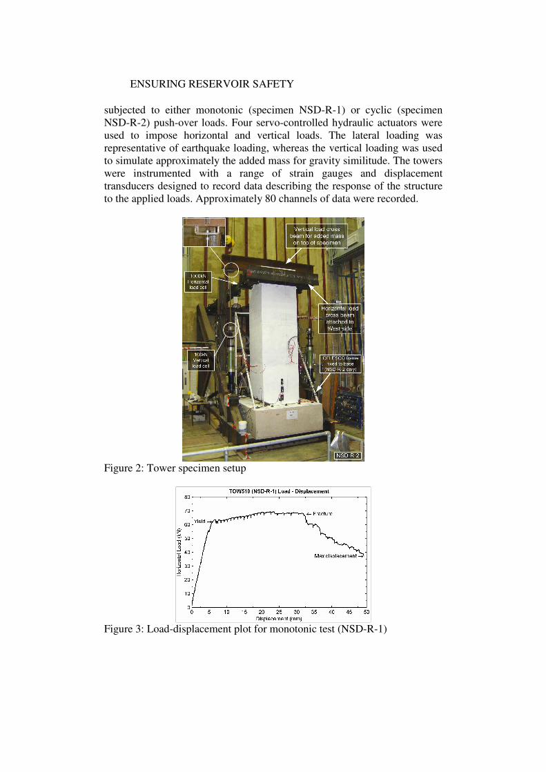
ENSURING RESERVOIR SAFETY
subjected to either monotonic (specimen NSD-R-1) or cyclic (specimen
NSD-R-2) push-over loads. Four servo-controlled hydraulic actuators were
used to impose horizontal and vertical loads. The lateral loading was
representative of earthquake loading, whereas the vertical loading was used
to simulate approximately the added mass for gravity similitude. The towers
were instrumented with a range of strain gauges and displacement
transducers designed to record data describing the response of the structure
to the applied loads. Approximately 80 channels of data were recorded.
Figure 2: Tower specimen setup
Figure 3: Load-displacement plot for monotonic test (NSD-R-1)

SABATINO, CREWE, DANIELL & TAYLOR
Test results
Monotonic test results indicated that the response of specimen NSD-R-1
was characterised by a tension failure of the under-reinforced section, with a
single large crack forming at the base of the tower. With reference to the
load-displacement plot (Figure 3), three distinct phases were observed:
1. The response of the specimen was stiff until first cracking was
observed; first yielding of the reinforcement followed.
2. As further displacement was imposed, some hardening was observed
until the peak load was reached.
3. Once fracture was initiated, the reaction force to the applied
displacement dropped rapidly until the test was terminated.
Figure 4: View of South-East corner crushing (NSD-R-2)
Figure 5: Normalized load-displacement plot.
The cyclic response of specimen NSD-R-2 confirmed the rigid body
behaviour, with localised damage at the base including spalling of the
concrete cover due to bar buckling (Figure 4). The following additional
conclusions can be obtained from the cyclic test results:
1. Considerable strength and stiffness degradation was observed with
increasing displacement amplitudes, making the monotonic envelope
(Figure 5) a non-conservative estimate of the tower capacity.
2. Extreme pinching was likely to be caused by bond deterioration
between the steel reinforcement and the concrete.
ENSURING RESERVOIR SAFETY
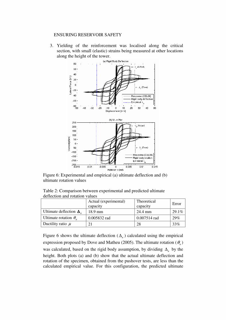
3. Yielding of the reinforcement was localised along the critical
section, with small (elastic) strains being measured at other locations
along the height of the tower.
Figure 6: Experimental and empirical (a) ultimate deflection and (b)
ultimate rotation values
Table 2: Comparison between experimental and predicted ultimate
deflection and rotation values
Actual (experimental)
capacity
Theoretical
capacity Error
Ultimate deflection u∆∆∆∆ 18.9 mm 24.4 mm 29.1%
Ultimate rotation uθ 0.005832 rad 0.007514 rad 29%
Ductility ratio µ 21 28 33%
Figure 6 shows the ultimate deflection ( u∆ ) calculated using the empirical
expression proposed by Dove and Matheu (2005). The ultimate rotation ( uθ )
was calculated, based on the rigid body assumption, by dividing u∆ by the
height. Both plots (a) and (b) show that the actual ultimate deflection and
rotation of the specimen, obtained from the pushover tests, are less than the
calculated empirical value. For this configuration, the predicted ultimate
SABATINO, CREWE, DANIELL & TAYLOR
deflection (or rotation) is over-estimated using the empirical relation. This
has considerable consequences on the ductility ratio of the tower (Table 2).
NUMERICAL MODELLING OF INTAKE TOWER SPECIMENS
Nonlinear finite element model
A Finite Element Analysis (FEA) of the intake tower specimens was
undertaken to investigate the suitability of the method for modelling typical
lightly reinforced concrete intake towers under seismic loading by
comparing the numerical results with the benchmark experimental results.
The modelling of the intake towers was performed using DIANA (release 9)
finite element package, a general purpose commercial finite element code
based on the displacement method (DIANA, 2006).
3D model definition
The finite element model geometry was based on the three-dimensional
properties of the physical specimens, with the actual steel reinforcement
layout modelled. The horizontal (monotonic and cyclic) load was applied in
the form of explicitly specified load steps through the definition of a time
curve. The vertical added mass was modelled as a point load applied at the
top of the model. The concrete cracking was modelled numerically using
the smeared crack approach to allow for a more versatile finite element
model. The total strain fixed crack model (DIANA, 2006) was selected for
its ability to formulate a single model with tensile and compressive
constituent laws. The steel reinforcement was modelled as an elasto-plastic
material with no ultimate strain defined.
Monotonic and cyclic analysis results
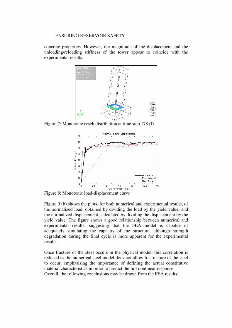
The duration of the monotonic analysis was 24 hours for 178 load steps,
using a dedicated Windows server. The analysis results indicated a localised
crack occurring at the base of the tower (Figure 7), with the rest of the
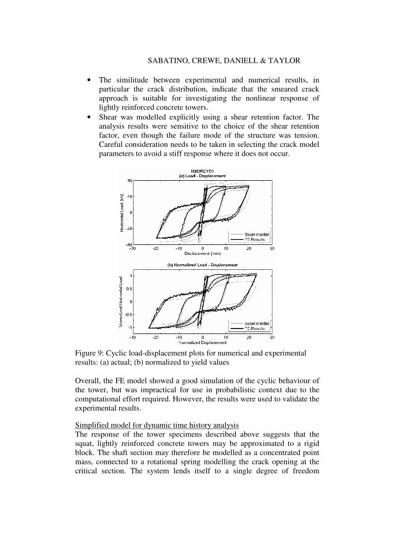
model remaining within the elastic range. Figure 8 shows the load
displacement results compared to the experimental results and the rigid body
motion calculated empirically. The FEA results coincide closely with the
rigid body motion, whereas the discrepancy with the experimental results
was due to the error in the measurement of the lateral displacement of the
tower, affected by the flexibility of the support frame.
The duration of the cyclic analysis was 24 days for 1279 load steps. The
cyclic load history was defined to simulate the experimental cyclic loading.
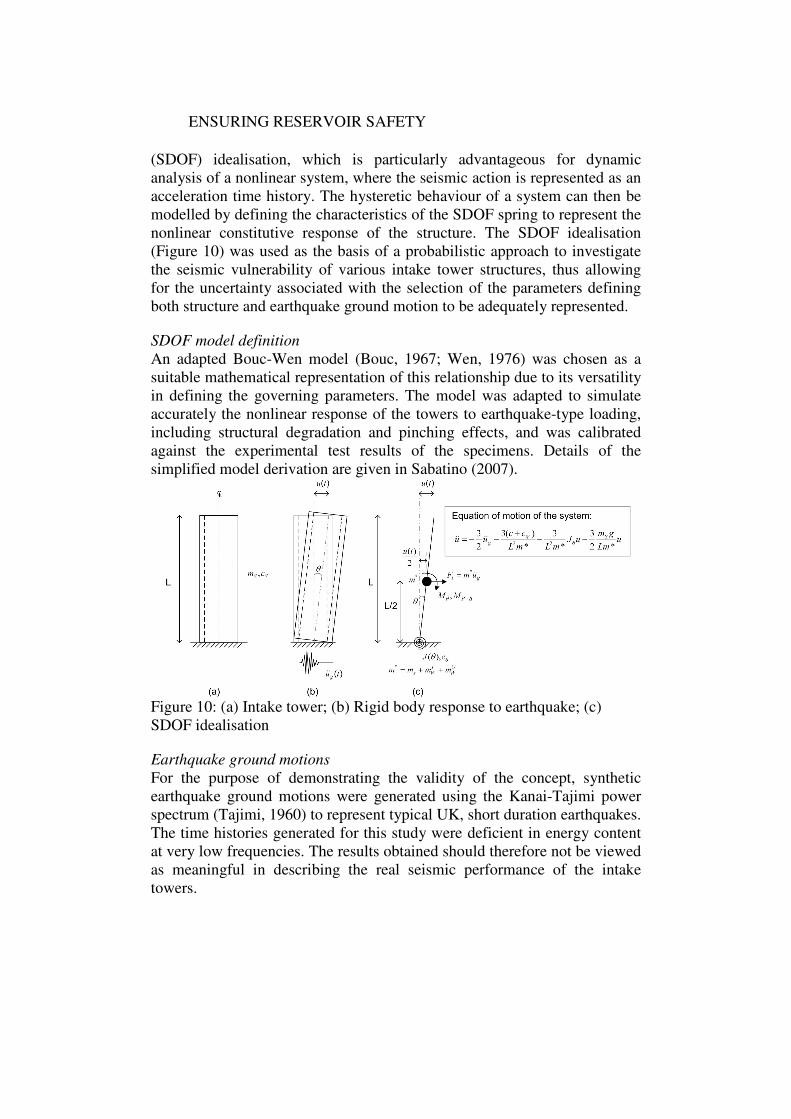
Figure 9 (a) shows the horizontal load against applied displacement plot for
the top of the model. By comparison to the experimental results (grey
curve), plotted for the same amplitude displacements, the numerical results
slightly under-estimate the capacity of the tower, probably due to some
difference between the numerical concrete strength and the actual tower
ENSURING RESERVOIR SAFETY
concrete properties. However, the magnitude of the displacement and the
unloading/reloading stiffness of the tower appear to coincide with the
experimental results.
Figure 7: Monotonic crack distribution at time step 178 (f)
Figure 8: Monotonic load-displacement curve
Figure 9 (b) shows the plots, for both numerical and experimental results, of
the normalized load, obtained by dividing the load by the yield value, and
the normalized displacement, calculated by dividing the displacement by the
yield value. The figure shows a good relationship between numerical and
experimental results, suggesting that the FEA model is capable of
adequately simulating the capacity of the structure, although strength
degradation during the final cycle is more apparent for the experimental
results.
Once fracture of the steel occurs in the physical model, this correlation is
reduced as the numerical steel model does not allow for fracture of the steel
to occur, emphasising the importance of defining the actual constitutive
material characteristics in order to predict the full nonlinear response
Overall, the following conclusions may be drawn from the FEA results:
SABATINO, CREWE, DANIELL & TAYLOR
• The similitude between experimental and numerical results, in
particular the crack distribution, indicate that the smeared crack
approach is suitable for investigating the nonlinear response of
lightly reinforced concrete towers.
• Shear was modelled explicitly using a shear retention factor. The
analysis results were sensitive to the choice of the shear retention
factor, even though the failure mode of the structure was tension.
Careful consideration needs to be taken in selecting the crack model
parameters to avoid a stiff response where it does not occur.
Figure 9: Cyclic load-displacement plots for numerical and experimental
results: (a) actual; (b) normalized to yield values
Overall, the FE model showed a good simulation of the cyclic behaviour of
the tower, but was impractical for use in probabilistic context due to the
computational effort required. However, the results were used to validate the
experimental results.
Simplified model for dynamic time history analysis
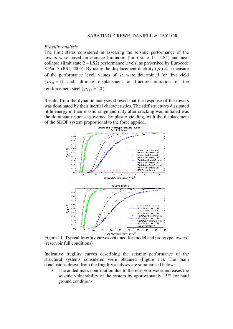
The response of the tower specimens described above suggests that the
squat, lightly reinforced concrete towers may be approximated to a rigid
block. The shaft section may therefore be modelled as a concentrated point
mass, connected to a rotational spring modelling the crack opening at the
critical section. The system lends itself to a single degree of freedom
ENSURING RESERVOIR SAFETY
(SDOF) idealisation, which is particularly advantageous for dynamic
analysis of a nonlinear system, where the seismic action is represented as an
acceleration time history. The hysteretic behaviour of a system can then be
modelled by defining the characteristics of the SDOF spring to represent the
nonlinear constitutive response of the structure. The SDOF idealisation
(Figure 10) was used as the basis of a probabilistic approach to investigate
the seismic vulnerability of various intake tower structures, thus allowing
for the uncertainty associated with the selection of the parameters defining
both structure and earthquake ground motion to be adequately represented.
SDOF model definition
An adapted Bouc-Wen model (Bouc, 1967; Wen, 1976) was chosen as a
suitable mathematical representation of this relationship due to its versatility
in defining the governing parameters. The model was adapted to simulate
accurately the nonlinear response of the towers to earthquake-type loading,
including structural degradation and pinching effects, and was calibrated
against the experimental test results of the specimens. Details of the
simplified model derivation are given in Sabatino (2007).
Figure 10: (a) Intake tower; (b) Rigid body response to earthquake; (c)
SDOF idealisation
Earthquake ground motions
For the purpose of demonstrating the validity of the concept, synthetic
earthquake ground motions were generated using the Kanai-Tajimi power
spectrum (Tajimi, 1960) to represent typical UK, short duration earthquakes.
The time histories generated for this study were deficient in energy content
at very low frequencies. The results obtained should therefore not be viewed
as meaningful in describing the real seismic performance of the intake
towers.
SABATINO, CREWE, DANIELL & TAYLOR
Fragility analysis
The limit states considered in assessing the seismic performance of the
towers were based on damage limitation (limit state 1 – LS1) and near
collapse (limit state 2 – LS2) performance levels, as prescribed by Eurocode
8 Part 3 (BSI, 2005). By using the displacement ductility ( µ ) as a measure
of the performance level, values of µ were determined for first yield
( 11 =LSµ ) and ultimate displacement at fracture initiation of the
reinforcement steel ( 202 =LSµ ).
Results from the dynamic analyses showed that the response of the towers
was dominated by their inertial characteristics. The stiff structures dissipated
little energy in their elastic range and only after cracking was initiated was
the dominant response governed by plastic yielding, with the displacement
of the SDOF system proportional to the force applied.
Figure 11: Typical fragility curves obtained for model and prototype towers
(reservoir full conditions)
Indicative fragility curves describing the seismic performance of the
structural systems considered were obtained (Figure 11). The main
conclusions drawn from the fragility analyses are summarised below:
• The added mass contribution due to the reservoir water increases the
seismic vulnerability of the system by approximately 15% for hard
ground conditions.
ENSURING RESERVOIR SAFETY
• The response of the structures was sensitive to the shape and
amplitude of the time histories used. The energy content of the
earthquake, as well as the frequency content of the time history,
greatly influenced the seismic performance of the structural models
considered.
• The apparently large PGA response required to reach the collapse
prevention limit state can be attributed to the geometrical
characteristics of the towers, where large displacements are required
before the centre of gravity of the structure is sufficiently displaced
to induce overturning P-∆ effects. Although all the reinforcement
steel may be fractured, the squat structure would respond in a rigid
body rocking motion, requiring a large PGA to cause it to overturn.
Due to time constraints, the earthquakes generated for the purpose of this
study were very crude. It was evident that a more precise evaluation of the
seismic event, preferably through the generation of site specific time
histories or at least by using more refined stochastic methods in simulating
ground motions allowing for the appropriate ground characteristics to be
modelled, would be required to obtain any significant performance
assessment of a real structure.
These conclusions have been drawn from a simplified model which has
been calibrated against quasi-static test results and a number of simplifying
assumptions have been used. The validity of the dynamic response of the
model requires further investigation, either through dynamic testing of tower
models or, preferably, through comparison with time history analyses using
more refined models over a range of parameters.
PROPOSED STAGED ASSESSMENT PROCEDURE FOR SEISMIC
PERFORMANCE EVALUATION
The proposed staged assessment procedure, described below, allows for a
gradual increase in the complexity of the analysis where necessary.
Stage 1: An initial performance assessment of the tower can be carried out
using existing capacity spectrum methods. The capacity curve of the tower
can be readily estimated using commercial packages, and the capacity
spectrum method allows for an initial estimation of the whether a given
seismic demand is likely to exceed the tower’s capacity and therefore
require a more rigorous nonlinear dynamic analysis.
Stage 2: Using a simplified model, a probabilistic, second stage analysis
would follow if necessary. A number of simulations can be carried out to
obtain fragility curves for the structure for various loading conditions and
performance requirements. The Engineer can then determine the
vulnerability of the tower for a given seismic hazard level, and establish
whether there is the need for a more detailed, and costly, FE analysis.
SABATINO, CREWE, DANIELL & TAYLOR
Stage 3: A nonlinear FE analysis would only be required for those cases
where, based on the fragility analysis results from Stage 2, the seismic
demand exceeded the capacity of the tower. By selecting a few time
histories, identified in the previous stage as having the most significant
impact on the response of the tower, the dynamic time history analyses of
the tower would provide a more accurate estimate of the structural
performance.
CONCLUSIONS
Monotonic and cyclic pushover tests of scaled lightly reinforced intake
tower models indicated that their response was characterised by a localized
tensile failure at the base of the tower. The rest of the tower behaved as a
rigid block, with negligible flexural response. Significant strength and
stiffness degradation were observed for the cyclic test, with the monotonic
envelope providing a non-conservative estimate of the capacity of the
structure. The response of the towers indicated that the empirical method
proposed by Dove and Matheu (2005) to calculate the ultimate deflection
capacity of intake towers over-estimated the actual capacity of the
specimens tested. Further experimental studies would be needed to clarify
this issue.
The test results were compared to a FE model of the specimens, capable of
simulating the crack propagation using a smeared crack material model for
the concrete. The computational effort required to run the analyses made
this approach not viable for use in a dynamic time history analysis. A
simplified SDOF idealisation was developed and used to perform Monte
Carlo type analyses of the towers for different loading conditions and
performance levels.
Based on the results obtained, the proposed simplified model was shown to
be a credible tool for the dynamic analysis of lightly reinforced concrete
intake tower structures. However, gross simplifications have been assumed
in defining both the structure and the synthetic earthquakes used in the
analyses. Although it provides a useful tool for the seismic vulnerability
assessment of the towers, it should be used as a first approximation. The
good fit to the quasi-static cyclic response of the actual towers does not
guarantee that the dynamic simulation accurately matches the behaviour of a
real tower. The uncertainty associated with the variability of the parameters
defining the structure and earthquake, as well as the sensitivity of the
response to the energy content and shape of the time history, implies that a
risk-based approach should be adopted for assessing the performance of the
intake towers.
ENSURING RESERVOIR SAFETY
ACKNOWLEDGEMENTS
The authors would like to acknowledge the financial assistance provided by
EPSRC under Grant Ref. GR/R93964/01, and KBR and Scottish &
Southern Energy for their support as Project Partners.
REFERENCES
Bouc, R., 1967. Forced vibration of mechanical systems with hysteresis.
Proceedings of the 4th
Conference on Nonlinear Oscillations, Prague.
BSI, 2004. BS EN1998-1: Eurocode 8: Design of structures for earthquake
resistance. Part 1: General rules, seismic actions and rules for buildings.
British Standards Institution.
BSI, 2005. BS EN 1998-3: Eurocode 8: Design of structures for earthquake
resistance. Part 3: Assessment and retrofitting of buildings. British
Standards Institution.
Charles, J.A., Abbiss, C.P., Gosschalk, E.M. and Hinks, J.L., 1991. An
engineering guide to seismic risk to dams in the United Kingdom.
Building Research Establishment, Garston.
DIANA, 2006. Finite Element Analysis – User’s Manual. Release 9. TNO,
Delft.
Dove, R.C. and Matheu, E.E., 2005. Ultimate Deflection Capacity of Lightly
Reinforced Concrete Intake Towers. ACI Structural Journal, Vol. 102,
Issue 2, pp. 214-223.
Harris, H.G. and Sabnis, G.M., 1999. Structural modelling and experimental
techniques (2nd
ed.), CRC Press, Boca Raton, pp.62-67.
ICOLD, 2002. Seismic design and evaluation of structures appurtenant to
dams, Guidelines. Bulletin 123.
Institution of Civil Engineers, 1998. An application note to An engineering
guide to seismic risk to dams in the United Kingdom. Thomas Telford,
London.
Sabatino, R., 2007. Seismic performance assessment of lightly reinforced
intake towers in reservoirs. Ph.D. thesis, University of Bristol.
Tajimi, H., 1960. A statistical method of determining the maximum response
of a building structure during an earthquake. Proceedings of the 2nd
World Conference on Earthquake Engineering, Tokyo, Japan, Vol. 2, pp.
781-798.
U.S. Army Corps of Engineers (USACE), 2003. Engineering and Design -
Structural Design and Evaluation of Outlet Works, Publication No. EM
1110-2-2400.
Wen, Y.K., 1976. Method of random vibration of hysteresis systems. Journal
of the Engineering Mechanics Division, ASCE, Vol. 116, No. 8, pp.
1798-1811.