Embed Size (px)
Citation preview
Nonlinear and Dual-Parameter Chaotic Vibrations ofLumped Parameter Model in Blisk under CombinedAerodynamic Force and Varying Rotating SpeedW. Zhang ( [email protected] )
Beijing University of TechnologyL. Ma
Beijing University of TechnologyY. F. Zhang
Shenyang Aerospace UniversityK. Behdinan
University of Toronto
Research Article
Keywords: Blisk structure, parametric and external excitations, lumped parameter model, amplitude-frequency response curves, dual parameter chaotic vibrations
Posted Date: September 20th, 2021
DOI: https://doi.org/10.21203/rs.3.rs-889062/v1
License: This work is licensed under a Creative Commons Attribution 4.0 International License. Read Full License
1
Nonlinear and Dual-Parameter Chaotic Vibrations of
Lumped Parameter Model in Blisk under Combined
Aerodynamic Force and Varying Rotating Speed
W. Zhang a,1*, L. Ma a,2, Y. F. Zhangb,3*, K. Behdinanc,4
a Beijing Key Laboratory of Nonlinear Vibrations and Strength of Mechanical Structures
College of Mechanical Engineering, Beijing University of Technology
Beijing 100124, P. R. China
b School of Aerospace Engineering, Shenyang Aerospace University
Liaoning 110136, P. R. China
c Department of Mechanical & Industrial Engineering, University of Toronto
5 King's College Road, Toronto, Ontario, M5S 3G8 Canada
1Email: [email protected], 2Email: [email protected]
3Email: [email protected], 4Email: [email protected]
Running Headline: Dual-Parameter Chaotic Vibrations of Blisk
Submitted to: Nonlinear Dynamics, September 8, 2021
Number of Pages: 55
Number of Figures: 22
Number of Tables: 2
* Corresponding Authors: Emails: [email protected], [email protected]
2
Abstract
In this paper, the nonlinear and dual-parameter chaotic vibrations are investigated for
the blisk structure with the lumped parameter model under combined the aerodynamic
force and varying rotating speed. The varying rotating speed and aerodynamic force are
respectively simplified to the parametric and external excitations. The nonlinear governing
equations of motion for the rotating blisk are established by using Hamilton’s principle.
The free vibration and mode localization phenomena are studied for the tuning and
mistuning blisks. Due to the mistuning, the periodic characteristics of the blisk structure
are destroyed and uniform distribution of the energy is broken. It is found that there is a
positive correlation between the mistuning variable and mode localization factor to exhibit
the large vibration of the blisk in a certain region. The method of multiple scales is applied
to derive four-dimensional averaged equations of the blisk under 1:1 internal and principal
parametric resonances. The amplitude-frequency response curves of the blisk are studied,
which illustrate the influence of different parameters on the bandwidth and vibration
amplitudes of the blisk. Lyapunov exponent, bifurcation diagrams, phase portraits,
waveforms and Poincare maps are depicted. The dual-parameter Lyapunov exponents and
bifurcation diagrams of the blisk reveal the paths leading to the chaos. The influences of
different parameters on the bifurcation and chaotic vibrations are analyzed. The numerical
results demonstrate that the parametric and external excitations, rotating speed and
damping determine the occurrence of the chaotic vibrations and paths leading to the
chaotic vibrations in the blisk.
Keywords: Blisk structure, parametric and external excitations, lumped parameter model,
amplitude-frequency response curves, dual parameter chaotic vibrations
3
1. Introduction
With the development of the aviation industry, the aero-engines are developing
towards the light weight, high thrust-weight ratio and high reliability. The blisk is a novel
structure of the aero-engine. The blisk structures of the fan and compressors are the
effective technologies to improve the performance of the durability and reliability for the
aero-engines [1]. Comparing with the traditional blade and disk structures, the advantages
of the blisk structures lead to the widely application in the aero-engines. However, due to
the light and thin structural characteristics and high rotating speed of the blisk, the
vibration amplitudes increase rapidly with the change of the aerodynamic force. The
thinner the blisk is, the larger the vibration amplitudes of the blisk become, which may
even result in the chaotic vibrations. The chaotic vibrations are harmful to the stability and
safety of the aero-engines. Therefore, in order to avoid the chaotic vibrations of the
aero-engines, we must investigate the chaotic dynamics of the blisk thoroughly. The
novelty of this paper is that the nonlinear and dual-parameter chaotic vibrations are
investigated for the blisk with the lumped parameter model under combined the varying
rotating speed and aerodynamic force. We focus on the dual-parameter chaotic dynamic
responses of the blisk. The influences of several parameters on the nonlinear dynamics are
mainly analyzed for the blisk structure
Based on the research results about the free vibration [2,3] and stability analysis [4,5]
of the rotary blade, scholars pay more attentions to study the influences of a single
parameter on the chaotic vibrations [6,7] of the blade. Especially, when considering the
complexity of the operating condition for the blisk structure, the current researches are far
from the requirements for analyzing the complex nonlinear dynamics of the blisks. If we
want to investigate the chaotic vibrations of the blisks systematically, we must consider
the combination of different parameters as much as possible, which may lead to the
chaotic vibrations of the blisks. The dual-parameters are referred to any combination of
the parametric and external excitation, damping and rotating speed in the blisk structure.
The chaos, a seemingly random motion, highly depends on the initial conditions of
the nonlinear dynamical systems [8]. When the systems subject to the complex excitations,
the chaotic vibrations more likely happen in the rotary machines [9]. Researchers devoted
more attentions to the nonlinear vibrations of the blades [10-15]. However, these studies
ignored the influences caused by the interactions among different parameters on the
4
nonlinear vibrations of the blade structure. In order to accurately predict and investigate
the nonlinear dynamic responses of the blisk structures, it is necessary for us to discuss
modal interactions of the blisk structure. The free vibration of the blisk structure is more
complex than that of a single blade [16]. Thus, as the basis of the nonlinear coupling
vibrations for the blisk structures, the modal analysis is of great importance. Generally,
three different methods were used to study the natural vibration characteristics of the blisk
structures, namely, the reduced-order modeling (ROM) techniques [17-19], experiment
methods [20,21] and numerical simulations [22,23]. The harmonic balance method [24],
eigenmode method [25,26] and parameter identification method [27,28] were used to
establish the reduced-order model of the blisk structures. Tang et al. [29,30] presented an
extension of the reduced-order model technique based on the component mode mistuning.
Sun et al. [31,32] utilized the energy-based finite element method (FEM) to investigate the
free vibration of the hard-coating blisk. Zhang et al. [33] studied the vibrations of the
rotating pretwisted composite tapered blade with the graphene coating layers. Zhang et al.
[34] investigated the multi-pulse jumping double-parameter chaotic dynamics of the
eccentric rotating ring truss antenna under combined the parametric and external
excitations. Unfortunately, up till now, almost all ROM methods, including system
identification and eigenmode methods, are utilized to analyze the data-driven empirical
models. When the parameters change slightly, the accuracy of the ROM will be greatly
reduced. Since the dimension of the equations constructed by the reduced-order model is
still too high for the analysis of the chaotic vibration for the blisk structures, few
researchers carried out the qualitative investigation about the chaotic vibrations of the
blisk structures based on the ROM technique.
In fact, the vibrations of the blisks are mostly nonlinear. To understand and solve
engineering problems, researchers begin to study the nonlinear vibrations of the blisk
structures. Salas et al. [35] used two methods to comparatively study the validity of the
noncyclic reduced lumped parameter models and the forced vibrations of the mistuning
blisk structures. Considering the effects of the vibration reduction for the damping coating,
Yan et al. [36] discussed the forced vibrations of the coated aero-engine blisk. Han and
Mignolet [37] predicted the forced dynamic responses of the damped mistuned disk.
Willeks et al. [38] studied the response reduction of the bladed disks with the aerodynamic
damping by using the harmonic mistuning. Gao et al. [39] gave the application of the
hard-coating damper to the mistuned blisk for the passive vibration reduction. Chen [40]
investigated the vibration reduction of the blisk by the damping hard coating and gave its
5
mistuning design. Feng and Jing [41] found that at the low frequencies, the vibration
isolation of the structures can be remarkably improved by using the nonlinear properties.
Usually, the contact state among the components of the mechanical structures is not
consummate. Therefore, the impact of the contact and friction can not be ignored when
studying the nonlinear vibrations of the blisk structures. Laxalde et al. [42] presented the
qualitative analysis of the forced dynamic responses for the blisk with the friction ring
dampers. Salas et al. [43] gave a mistuned analysis of the forced dynamic responses for an
embedded compressor blisk using a reduced-order model. Beirow et al. [44] utilized the
equivalent model to explore the influence of the aerodynamic load on the dynamic
responses of a blisk. Sarrouy et al. [45] simplified the blades to six identical beams
clamped at the disk and explored the complete bifurcation phenomena of the blisk.
Hoskoti et al. [46] studied the instability of the vortex induced vibrations for a blade. Gu
et al. [47] investigated the free vibration of the rotating cantilever pre-twisted panel with
the geometric imperfection of the initial exponential function type. Najafi [48] researched
the stability and nonlinear vibrations of a rotating bladed disk at the critical speed.
Although many researches are focused on the nonlinear dynamics of the blades, the
literatures related to the chaotic dynamics of the lumped parameter model for the blisk
structures are less. Researches seem to be blank on the dual-parameter chaotic vibrations
of the blisk structures. Considering the coupling influences of various parameters on the
nonlinear vibrations of the blisk, the dual-parameter nonlinear vibrations of the lumped
parameter model are investigated for the blisk. The governing equations of motion for the
lumped parameter model of the blisk are established by applying Hamilton’s principle.
The influences of different parameters on the bifurcations are analyzed by using numerical
simulations. The free vibration and mode localization phenomenon [49,50] of the
mistuning blisk are investigated. When the structure has not the tuning, the energy of the
system is no longer uniformly distributed. The larger the mode localization factor is, the
larger the vibration amplitude is in a certain region. The amplitude-frequency response
curves of the blisk are investigated based on the averaged equations in the polar
coordinate under 1:1 internal resonance and principal parametric resonance [51]. The
dual-parameter Lyapunov exponents and bifurcation diagrams of the blisk are depicted.
The effects of the damping, perturbation rotating speed, steady-state rotating speed and
external excitation on the nonlinear dynamics are numerically investigated for the blisk
structure. The phase portraits, waveforms and Poincare maps are given to demonstrate the
nonlinear dynamic responses of the blisk structure.
6
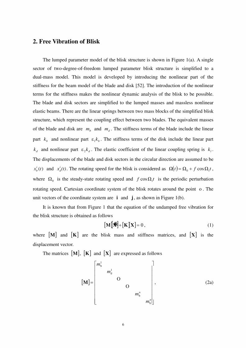
2. Free Vibration of Blisk
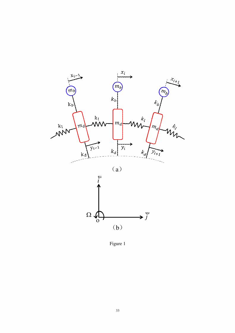
The lumped parameter model of the blisk structure is shown in Figure 1(a). A single
sector of two-degree-of-freedom lumped parameter blisk structure is simplified to a
dual-mass model. This model is developed by introducing the nonlinear part of the
stiffness for the beam model of the blade and disk [52]. The introduction of the nonlinear
terms for the stiffness makes the nonlinear dynamic analysis of the blisk to be possible.
The blade and disk sectors are simplified to the lumped masses and massless nonlinear
elastic beams. There are the linear springs between two mass blocks of the simplified blisk
structure, which represent the coupling effect between two blades. The equivalent masses
of the blade and disk are bm and dm . The stiffness terms of the blade include the linear
part bk and nonlinear part bk1 . The stiffness terms of the disk include the linear part
dk and nonlinear part dk2 . The elastic coefficient of the linear coupling spring is lk .
The displacements of the blade and disk sectors in the circular direction are assumed to be
)(txi
b and (t)xi
d . The rotating speed for the blisk is considered as tft 10 ΩcosΩΩ ,
where 0Ω is the steady-state rotating speed and tf 1Ωcos is the periodic perturbation
rotating speed. Cartesian coordinate system of the blisk rotates around the point o . The
unit vectors of the coordinate system are i and j , as shown in Figure 1(b).
It is known that from Figure 1 that the equation of the undamped free vibration for
the blisk structure is obtained as follows
0 XKXM , (1)
where M and K are the blisk mass and stiffness matrices, and X is the
displacement vector.
The matrices M , K and X are expressed as follows
n
n
m
m
m
m
b
b
1
d
1
b
M , (2a)
7
l
nn
bbl
bb
bb
llbb
bb
kukkkk
kk
kk
kkkukkk
kk
)cos2(00
0
0)cos2(
0
d
n
nn
22
l
1
d
11
11
K , (2b)
T11 n
d
n
bdb xxxx X . (2c)
where u is the phase angle between two adjacent blades.
The disk vibrates freely with the frequency . The following formula is obtained as
02 XMK . (3)
Equation (2) is expressed by the eigenvalues and eigenvectors
0 XIA , (4)
where KMA1 , and I is the identity matrix.
The aforementioned parameters are respectively selected as 0.05kgbm ,
kg1.0dm , mN105.7 5bk , mN106 5dk , mN104 5lk .
It is assumed that the mistuned mass and mistuned stiffness of the blades respectively
follow the random normal distributions with the mean value 0. We consider as the
change of the random mistuned mass and as the varying of the random mistuned
stiffness for the blades. The natural frequencies and mode shapes of the blades are
investigated. Table 1 gives the first fifth natural frequencies of the blades without
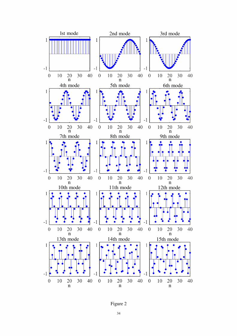
mistuning, which means that and are taken as 0 in this case. Figure 2 demonstrates
the first fifteen mode shapes of the blades without the mass mistuning or stiffness
mistuning. The vibration modes of the blades present the standard sinusoidal manner,
which indicates that the distribution of the energy on the blades is completely uniform.
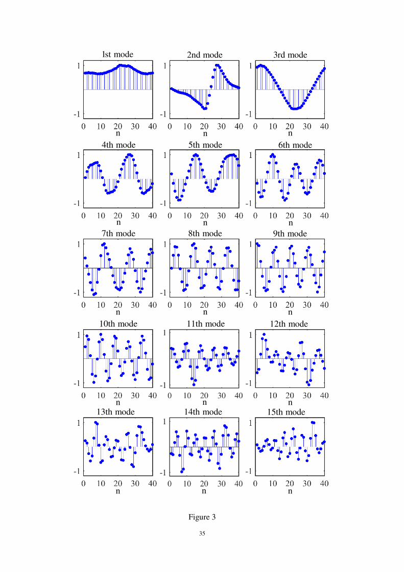
Figure 3 exhibits the first fifteen vibration modes of the blades with the mass
mistuning, where the change of the random mistuned mass for the blades is %2 . The
mass mistuning values bm of the blades are indicated in Table 2. In Figure 3, it is seen
that vibration modes of the blades are no longer sinusoidal. Since the mass mistuning
destroys the periodic properties of the blisk, which leads to the transfer of the energy
between the blades, and finally leads to the mode localization. The aforementioned results
illustrate that the stiffness mistuning also leads to the mode localization of the blades.
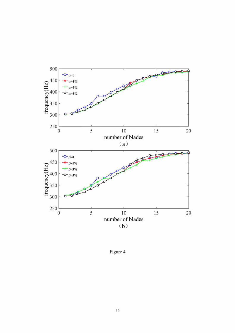
When the changes of the random mistuned mass are respectively chosen as %1 ,
8
%3 and %5 , the natural frequencies of the blades without the mistuning 0
and with mass mistuning in four cases are given, as shown in Figure 4(a). It is found that
mass mistuning leads to the reduction of the first eleven natural frequencies for the blade.
However, the mass mistuning almost has no the effect on the natural frequencies which are
higher than the eleventh-order natural frequencies. Different changes of the mistuned
masses for the blades have the same influence on the natural frequencies of the blade.
When the changes of the random mistuned stiffness are %1 , %3 and %5 ,
the natural frequencies of the tuning 0 and detuning blades in four stiffness forms are
depicted, as shown in Figure 4(b), which illustrates that stiffness detuning will increase the
eleventh-order to sixteenth-order natural frequencies of the blades. However, the natural
frequencies higher than the sixteenth-order keep unchanged when the stiffness mistuning.
It is pointed out that the larger the value of the change of the mistuned stiffness is, the
more obviously the natural frequencies of blades decrease or increase.
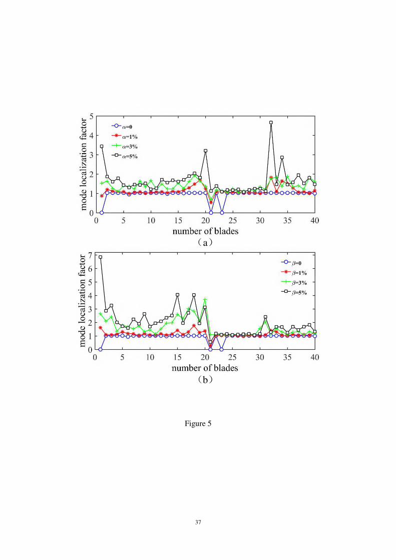
Using Euclidean norm to define the mode localization factors, we have
n
jii
i
n
jii
imax
An
An
A
L
,1
2
,1
22
1
1
1
1
, (5)
where maxA is the largest vibration amplitude of the blades, n is the quantity of the
blades, j is the number of the blade with the largest amplitude, iA is the amplitude of
the ith blade.
When the changes of the random mistuned mass are %1 , %3 and %5 ,
Figure 5(a) demonstrates the mode localization factors of the blades without the mistuning
0 and with mass mistuning in four cases. Figure 5(b) illustrates the mode localization
factors of the blades without the mistuning and with stiffness mistuning in four cases when
0 , %1 , %3 and %5 . In Figure 5, the mode localization factors are less than or
equal to 1 when the blisk structure vibrates without the mistuning. By contrary, when the
blisk structure vibrates with the mistuning, the mode localization factors are greater than
or equal to 1. When the mode shape of the blade is sinusoidal and mode localization factor
is less than 1, the mode localization phenomenon will not appear. Correspondingly when
the mode shapes of the blades do not distribute sinusoidally and mode localization factor
is greater than 1, the mode localization phenomenon occurs. The larger or are, the

9
larger the mode localization factors of the blades become. As a combination, the small
damping of the blisk structure will leads to the large amplitude vibration. Thus, it is urgent
for us to study the nonlinear dynamical behaviors of the blisk.
3. Nonlinear Governing Equations of Motion
Based on the lumped parameter model of the blisk in Figure 1, we establish the
dynamic model of the blisk. The displacements of the blade bm and disk dm are
expressed as
jiR Rtxibi , jiR rtyidi . (6)
The velocity and acceleration of the blade and disk are obtained as follows
jiR ΩΩ iibi xRx , jiR ΩΩ iidi yry , (7)
and
jR iiiibi xRxxRx ΩΩΩ2iΩΩ 22 , (8a)
jiR iiiidi yryry ΩΩyΩ2ΩΩ 22 . (8b)
The variation of the kinetic energy is given by
didid
n
i
bibib mmK RRRR 1
]ΩyΩΩΩ[ 22
1
iiidiii
n
i
b yrymxxRxm
. (9)
The potential energy U consists of the elastic potential energy 1U of the blades,
elastic potential energy 2U of the disks and elastic potential energy 3U of the linear
springs. These potential energy expressions are given as follows
321 UUUU , (10a)
n
iiii yxk
yxk
U
1i
4b12b
142
, (10b)
n
ii yk
yk
U
1i
4d12d
242
. (10c)
n
ii yyk
U
1i
2
1
c
32
. (10d)
10
The variation of the potential energy is obtained as
iiiib
n
i
iidiid yxyxkyykyykU
3
1
1
3
2[
1
3
1c yy iiiiiiiib yykyxyxk . (11)
The aerodynamic force subjects to the mass block of the blade. Therefore, we have
tptpptp iiii 22210 ΩcosΩsin . (12)
The variation of the virtual work done by the first type of the aerodynamic force is
denoted as follows
n
i
ii xtpW
1
1 . (13)
The differential governing equation of motion for the rotating blisk is established by
adopting Hamilton principle
t
tdWUK0
0)( , (14)
where t is time and is the variation.
Substituting K , U and W into equation (14), the differential governing
equations of motion for the rotating blisk are derived in terms of the displacements
:ix
0ΩΩ 1
3
1
1
2
iiiiib
n
i
iibiib xxtpyxkyxkxRxm , (15a)
:2ix
i
n
i
iibiibididiid yyxkyxkykykyrym 1
3
1
3
2
2ΩΩ
0
1i
211c
n
iiiiii yyyyyyk , (15b)
where 1 and 2 are the structural damping terms of the blisk.
The displacement relationships between two adjacent blades and two adjacent disk
sectors are described as follows
i
iu
i xx e1 , i
iv
i yy e1 , (16)
where u is the phase angle between two adjacent blades, and v is the phase angle
between two adjacent disk sectors.
11
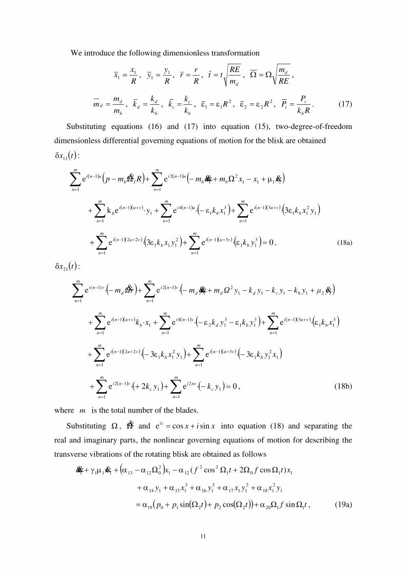
We introduce the following dimensionless transformation
R
xx 1
1 , R
yy 1
1 , R
rr ,
dm
REtt ,
RE
md ,
b
dd
m
mm ,
b
d
dk
kk ,
b
cc
k
kk , 2
11 R , 2
22 R , Rk
PP
b
i
i . (17)
Substituting equations (16) and (17) into equation (15), two-degree-of-freedom
dimensionless differential governing equations of motion for the blisk are obtained
:11 tx
1111
2
1
1
12
1
1 μΩeΩe xxxmxmRmp bb
m
n
uni
1b
m
n
uni
1
2
11
1
313
11
1
14
1
1
1 ε3·eε·e·ek yxkxky b
m
n
vuni
b
m
n
uni
m
n
vuni
b
0·e3·e 3
11
1
312
111
1
221
ykyxk b
m
n
vuni
b
m
n
vuni, (18a)
:21 tx
121b111
2
1
1
12
1
)1( ·e·e yμykykykyΩmymrΩm cddd
m
n
vni
d
m
n
vni
3
11
1
313
11
3
12
1
14
1
1
1 ·e·e·e xkykykxk b
m
n
vuni
bd
m
n
vni
b
m
n
vuni
1
2
11
1
31
1
2
11
1
221 3·e3·e xykyxk b
m
n
vuni
b
m
n
vuni
0·e2·e 1
1
2
1
1
12
ykyk c
m
n
nvi
c
m
n
vni , (18b)
where m is the total number of the blades.
Substituting Ω , Ω and xixix sincose into equation (18) and separating the
real and imaginary parts, the nonlinear governing equations of motion for describing the
transverse vibrations of the rotating blisk are obtained as follows
1101
22
121
2
012131111 )ΩcosΩ2Ωcos(Ωx xtftfxx
1
2
118
2
1117
3
116
3
115114 yxyxyxy
tftptpp 11202221019 ΩsinΩcossin , (19a)
12
1221101
22
221
2
022231221 )ΩcosΩ2Ωcos(Ωy xytftfyy
tfyxyxyx 1129
2
11281
2
127
3
126
3
125 ΩsinΩ , (19b)
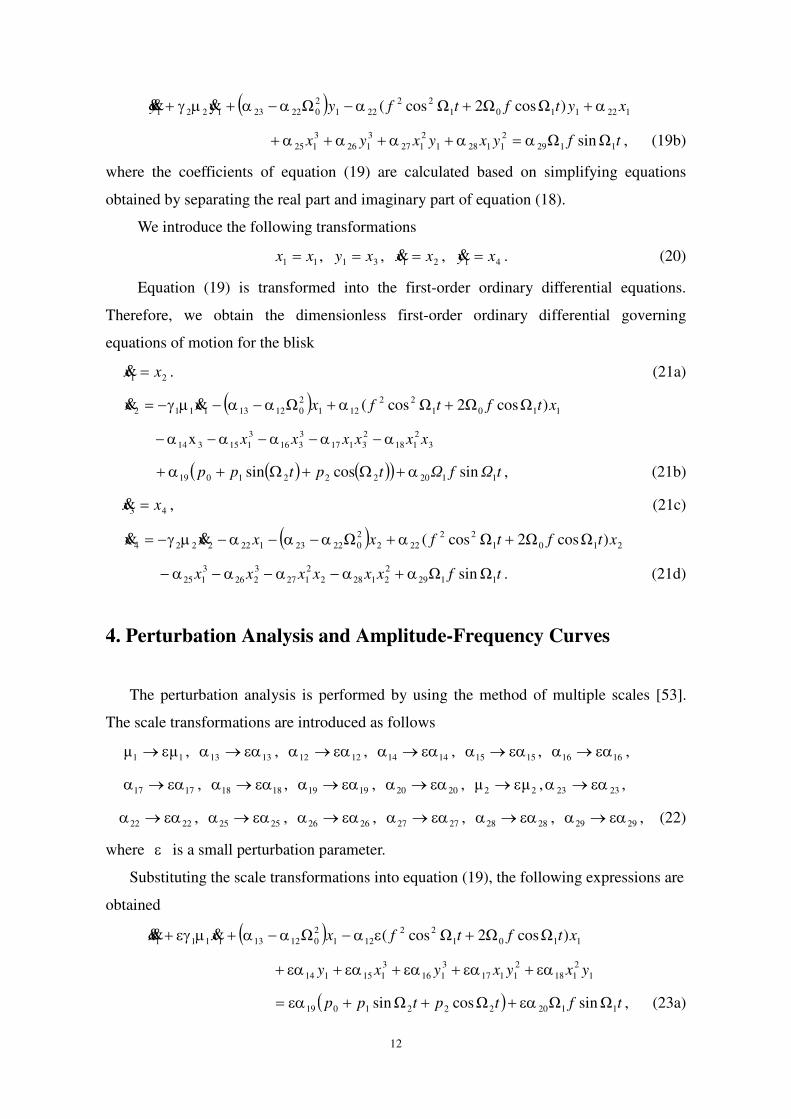
where the coefficients of equation (19) are calculated based on simplifying equations
obtained by separating the real part and imaginary part of equation (18).
We introduce the following transformations
11 xx , 31 xy , 21 xx , 41 xy . (20)
Equation (19) is transformed into the first-order ordinary differential equations.
Therefore, we obtain the dimensionless first-order ordinary differential governing
equations of motion for the blisk
21 xx . (21a)
1101
22
121
2
012131112 )ΩcosΩ2Ωcos(Ωxx xtftfx
3
2
118
2
3117
3
316
3
115314x xxxxxx
tΩfΩtptpp 11202221019 sincossin , (21b)
43 xx , (21c)
2101
22
222
2
022231222224 )ΩcosΩ2Ωcos(Ωxx xtftfxx
tfxxxxxx 1129
2
21282
2
127
3
226
3
125 ΩsinΩ . (21d)
4. Perturbation Analysis and Amplitude-Frequency Curves
The perturbation analysis is performed by using the method of multiple scales [53].
The scale transformations are introduced as follows
11 μμ , 1313 , 1212 , 1414 , 1515 , 1616 ,
1717 , 1818 , 1919 , 2020 , 22 μμ , 2323 ,
2222 , 2525 , 2626 , 2727 , 2828 , 2929 , (22)
where is a small perturbation parameter.
Substituting the scale transformations into equation (19), the following expressions are
obtained
1101
22
121
2
012131111 )ΩcosΩ2Ωcos(Ω xtftfxxx
1
2
118
2
1117
3
116
3
115114 yxyxyxy
tftptpp 11202221019 ΩsinΩΩcosΩsin , (23a)
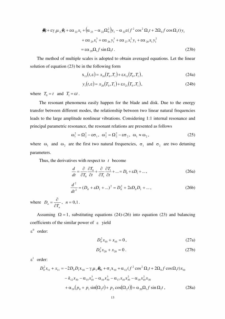
13
1101
22
221
2
022231221221 )ΩcosΩ2Ωcos(Ω ytftfyxyy
2
11281
2
127
3
126
3
125 yxyxyx
tf 1129 ΩsinΩ . (23b)
The method of multiple scales is adopted to obtain averaged equations. Let the linear
solution of equation (23) be in the following form
1011101011 ,,,x TTxTTxt , (24a)
102110201 ,,, TTxTTxty , (24b)
where tT 0 and tT 1 .
The resonant phenomena easily happen for the blade and disk. Due to the energy
transfer between different modes, the relationship between two linear natural frequencies
leads to the large amplitude nonlinear vibrations. Considering 1:1 internal resonance and
principal parametric resonance, the resonant relations are presented as follows
1
2
2
2
1 Ω , 2
2
2
2
2 Ω , 21 , (25)
where 1 and 2 are the first two natural frequencies, 1 and
2 are two detuning
parameters.
Thus, the derivatives with respect to t become
...... 101
1
0
0
DDt
T
Tt
T
Tdt
d, (26a)
...2...)( 10
2
0
2
102
2
DDDDDdt
d , (26b)
where n
nT
D
, 1,0n .
Assuming 1 , substituting equations (24)-(26) into equation (23) and balancing
coefficients of the similar power of yield
0 order:
01010
2
0 xxD , (27a)
02020
2
0 xxD . (27b)
1 order:
10101
22
12101101110101111
2
0 )ΩcosΩ2Ωcos(xx2 xtftfxDDxxD
30
2
1018
2
301017
3
3016
3
10153012 xxxxxxxk
tftptpp 11202221019 ΩsinΩcossin , (28a)
14
20101
22
22202202220102121
2
0 )ΩcosΩ2Ωcos(xx2 xtftfxDDxxD
20
2
1027
3
2026
3
10251021 xxxxxk
tfxx 1129
2
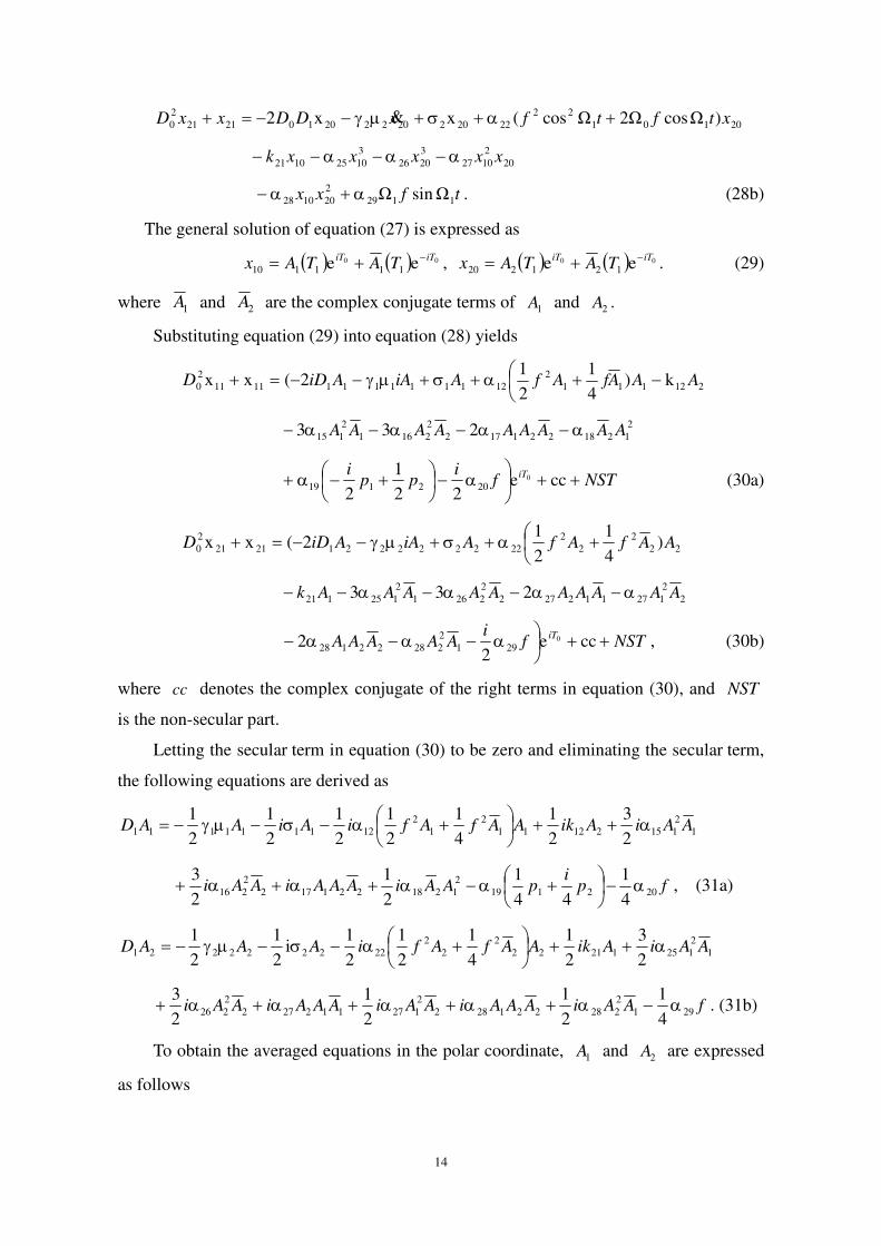
201028 ΩsinΩ . (28b)
The general solution of equation (27) is expressed as
00 ee 111110
iTiTTATAx
, 00 ee 121220
iTiTTATAx
. (29)
where 1A and 2A are the complex conjugate terms of 1A and 2A .
Substituting equation (29) into equation (28) yields
212111
2
1211111111111
2
0 k)4
1
2
12(xx AAAfAfAiAAiDD
2
1218221172
2
2161
2
115 233 AAAAAAAAA
NSTfi
ppi iT
cce
22
1
20
202119 (30a)
22
2
2
2
2222222212121
2
0 )4
1
2
12(xx AAfAfAiAAiDD
2
2
127112272
2
2261
2
125121 233 AAAAAAAAAAk
NSTfi
AAAAAiT
cce
22 0
291
2
22822128 , (30b)
where cc denotes the complex conjugate of the right terms in equation (30), and NST
is the non-secular part.
Letting the secular term in equation (30) to be zero and eliminating the secular term,
the following equations are derived as
1
2
11521211
2
1
2
1211111112
3
2
1
4
1
2
1
2
1
2
1
2
1AAiAikAAfAfiAiAAD
221172
2
2162
3AAAiAAi fp
ipAAi 202119
2
12184
1
44
1
2
1
, (31a)
1
2
12512122
2
2
2
2222222212
3
2
1
4
1
2
1
2
1i
2
1
2
1AAiAikAAfAfiAAAD
2
2
127112272
2
2262
1
2
3AAiAAAiAAi fAAiAAAi 291
2
228221284
1
2
1 . (31b)
To obtain the averaged equations in the polar coordinate, 1A and 2A are expressed
as follows
15
11e2
11111
TiTaTA
, 12e2
11212
TiTaTA
. (32)
Substituting equation (32) into equation (31) and separating the real part and
imaginary part, the average equations in the polar coordinate system are derived as
follows
21
3
216212
2
121811
2
12111
1
1 sin2
3k
2
1
2
12sin
8
1
2
1
aaaaafa
dT
da
fpaa 122011921
2
21174
1
4
122sin
2
1 , (33a)
21
2
21171
2
121
2
211711
3
115
1
1
1 22cos2
12cos
8
1
2
1
2
3
aafaaaaa
dT
da
21921
3
216212
2
1218
2
1214
1cos
2
3k
2
1
2
3
4
1paaaafa
, (33b)
21
3
125121
2
2128
2
22422222
1
2 sin2
3k
2
1
2
1
4
1
2
1
aaaafaa
dT
da
ffaaa 29222
2
22221
2
12274
12sin
8
122sin
2
1 , (33c)
21
3
125121
2
2128
2
1227
3
226
1
22 cos
2
3k
2
1
2
3
2
3
aaaaaaa
dT
da
2
2
22221
2
122722 2cos8
122c
2
1
2
1 faosaaa . (33d)
Based on equation (33), the amplitude-frequency response curves are investigated for
the rotating blisk. Some parameters obviously affect the nonlinear dynamic behaviors of
the lumped parameter model for the blisk. We mainly study influences of the rotating
speed, aerodynamic force, damping, coupling stiffness and cubic nonlinear terms on the
amplitude-frequency response curves of the blisk.
Letting 21 , when 02121 aa , the equations of the steady-state
vibration for the blisk are obtained as follows
2
219
2
121
2
211711
3
115
2
12201191114
1
4
1
2
1
2
3
4
1
4
1
2
1
pfaaaaafpa
2
2
2117
3
216212
2
121811
2
12 2sin2
1sin
2
3k
2
1
2
12sin
8
1
aaaaaaaf
1
2
121
2
2117 2cos8
12cos
2
1faaa
2
3
216212
2
1218 cos2
3k
2
1
2
3
aaaa ,
16
(34a)
2
2
122722
3
226
2
2229
2
2222222
1
2
3
4
1
4
1
2
1
aaaaffaa
2
2
2
222
2
1227
3
125121
2
2128 2sin8
12sin
2
1sin
2
3k
2
1
2
1
faaaaaaa
cos
2
3k
2
1
2
3 3
125121
2
2128 aaaa 2
2
2
222
2
1227 2cos8
12c
2
1 faosaa .
(34b)
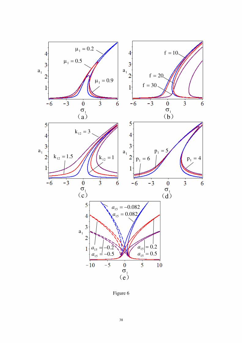
The amplitude-frequency response curves of the blisk are analyzed when the
parameters of equation (34) are respectively selected as
0.11 , 2.01 , 112 , 082.015 , 006.016 , 02.017 , 01.018 ,
119 , 112 k , 1f , 22 , 21 p , 025.02 p , 0.12 , 2.02 ,
122 , 01.025 , 05.026 , 01.027 , 01.028 , 0.129 , 121 k .
Letting 2 1a in equation (34a) and 1 1a in equation (34b), the amplitude
frequency response curves of the blades and disk subjected to the aerodynamic force are
obtained, as shown in Figures 6 and 7. In Figures 6 and 7, other parameters remain
unchanged except for the control parameters. The typical multi-valued phenomena occur,
which results in the jumping of the solution in equation (34).
Figure 6(a) demonstrates that the amplitudes and bandwidths of the blades decrease
with the increase of the damping 1 . The increase of the perturbation rotating speed f
and coupling stiffness 12k results in the increase of the amplitude and bandwidth for the
blades, as shown in Figures 6(b) and 6(c). The right-ward shift of the amplitude-frequency
curve occurs for the blades, as shown in Figure 6(b). Figure 6(d) illustrates that as the
aerodynamic force 1p increases, the amplitudes of the amplitude-frequency response
curves for the blades increase, but the bandwidth deceases. From Figures 6(a)-6(d), it is
shown that the blades have the hard spring properties. As the frequency 1 changes, the
multi-valued phenomena occur. When the cubic term 15a increases, Figure 6(e) depicts
that the amplitude-frequency response curves bend and are away from zero solution, and
the amplitudes of the dynamic responses decreases. When the nonlinear parameter 15a is
positive, the blades exhibit the hard spring properties. However, when the nonlinear
parameter 15a is negative, the blades have the soft spring properties. When value of 15a
17
is opposite, the amplitude-frequency response curves are symmetric.
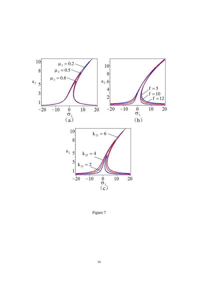
Figure 7 illustrates the influences of several parameters on the amplitude-frequency
response curves of the disk, including the damping 2 , perturbation rotating speed f
and coupling stiffness 21k . It is illustrated that the disk has the hard spring properties. The
results show that damping 2 and coupling stiffness
21k have almost the same effect on
the amplitude-frequency curves for the disk, as shown in Figures 7(a) and 7(c). In Figure
7(a), the damping 2 has no difference to the response bandwidth of the disk. Figure 7(b)
demonstrates that the right-ward shift or left-ward shift of the amplitude-frequency
response curves for the disk do not occur with the change of the perturbation rotating
speed f . It is pointed out that a smaller f results in the remarkable narrowing in the
response bandwidth and the enhancement of the amplitude for the disk.
5. Numerical Simulation of Dual-Parameter Chaos
In recent decades, a large variety of numerical methods have been developed to
detect the periodic and chaotic vibrations of the nonlinear dynamical systems. The
bifurcation diagrams and Lyapunov exponents have been the common choices for
investigating the chaotic vibrations of the structures with the geometric nonlinearity and
subjected to the various kinds of excitations. The bifurcation diagrams are the effective
tools detecting the periodic and chaotic vibrations with a single controlling parameter.
However, only depending on two-dimensional bifurcation diagrams is insufficient to
illustrate the existence of the chaotic dynamics for the dual-parameter nonlinear system in
three-dimensional (3D) space. Lyapunov exponents are used to distinguish the periodic
and chaotic vibrations. However, it is difficult to identify which type of the periodic
vibration appears in the nonlinear dynamical system according to Lyapunov exponents.
Therefore, to exceed the limitations of the traditional bifurcation diagrams and Lyapunov
exponent, the dual-parameter bifurcation diagrams are considered to study the periodic
and chaotic vibrations of the structure.
Based on equation (21), numerical simulations are performed to study the dynamic
behaviors of the lumped parameter model for the rotating blisk subjected to the
aerodynamic force. The dual-parameter Lyapunov exponents are numerically obtained by
using Benettin-Wolf algorithm. The numerical results of the dual-parameter bifurcation
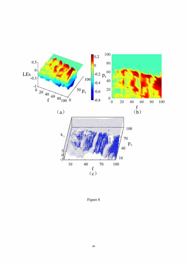
diagrams are constructed based on Runge-Kutta algorithm and Poincare map. Figure 8
18
shows 3D dual-parameter Lyapunov exponents and bifurcation diagrams of the blisk
versus the perturbation rotating speed f and aerodynamic force 0p . Obviously, there is
an excellent correspondence between Lyapunov exponents and bifurcation diagrams.
Based on 3D dual-parameter Lyapunov exponents, we gives the influences of one
parameter on the nonlinear dynamics of the blisk structure when another parameter is
regarded as a controlling parameter, as shown in Figures 9. These figures reveal clearly
how the system evolves between the periodic and chaotic vibrations.
The initial conditions and parameters of the blisk structure are respectively selected
0.11 , 3.021 , 7368.3917431 , 08.041 , 92.151 , 161 , 2.071 ,
76.081 , 5.091 , 9.020 , 0.12 , 6.022 , 2.149123 , 5.125 ,
09.2026 , 7.227 , 28.128 , 1.029 , 0.1Ω1 , 0.1Ω 2 , 501 p ,
102 p , 0.110 x , 101.020 x , 0.130 x , 1.040 x .
In the following analysis, the values of these parameters remain unchanged. Some
important parameters of the blisk, such as the structural damping, aerodynamic force and
rotating speed, are considered to analyze dual-parameter chaotic vibrations, respectively.
5.1 Effect of Perturbation Rotating Speed
Considering the effect of the perturbation rotating speed f and aerodynamic force
0p , the dual-parameter chaotic vibrations are studied for the blisk, and the paths to chaos
are explored. Based on 3D dual-parameter bifurcation diagrams and Lyapunov exponents,
single parameter bifurcation phenomena of the blisk are obtained by using the variable
controlling method. Selecting the perturbation rotating speed f and aerodynamic force
0p as two controlling parameters, the dual-parameter Lyapunov exponents exhibit the
regions where the dual-parameter chaotic vibrations occur, as shown in Figures 8(a) and
8(b), where damping terms 1 and
2 , and steady-state rotating speed 0Ω are given as
46.0μ1 , 46.0μ2 , 200Ω0 . In order to show the evolution process of the periodic
and chaotic vibrations, 3D dual-parameter bifurcation diagram is given in Figure 8(c).
In Figure 8(a), two horizontal axes respectively are the perturbation rotating speed
f and aerodynamic force 0p , and the vertical axis is the dual-parameter Lyapunov
exponents. We calculate four Lyapunov exponents of each point. Therefore, there are four
19
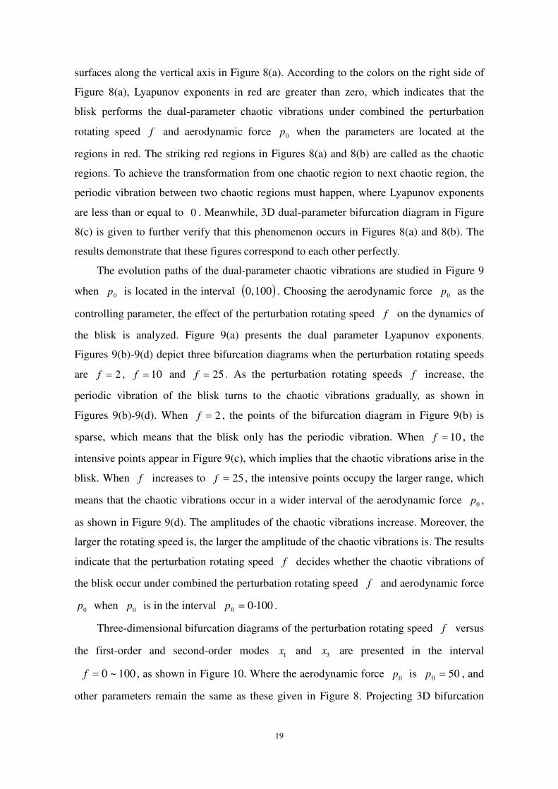
surfaces along the vertical axis in Figure 8(a). According to the colors on the right side of
Figure 8(a), Lyapunov exponents in red are greater than zero, which indicates that the
blisk performs the dual-parameter chaotic vibrations under combined the perturbation
rotating speed f and aerodynamic force 0p when the parameters are located at the
regions in red. The striking red regions in Figures 8(a) and 8(b) are called as the chaotic
regions. To achieve the transformation from one chaotic region to next chaotic region, the
periodic vibration between two chaotic regions must happen, where Lyapunov exponents
are less than or equal to 0 . Meanwhile, 3D dual-parameter bifurcation diagram in Figure
8(c) is given to further verify that this phenomenon occurs in Figures 8(a) and 8(b). The
results demonstrate that these figures correspond to each other perfectly.
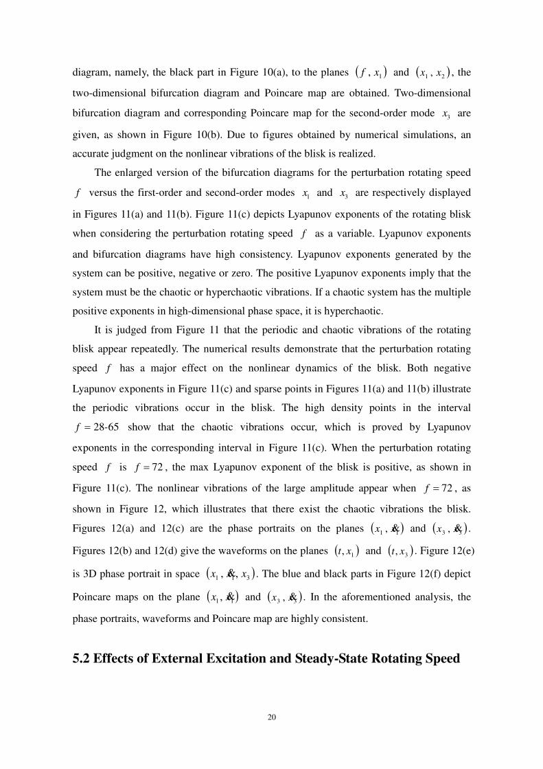
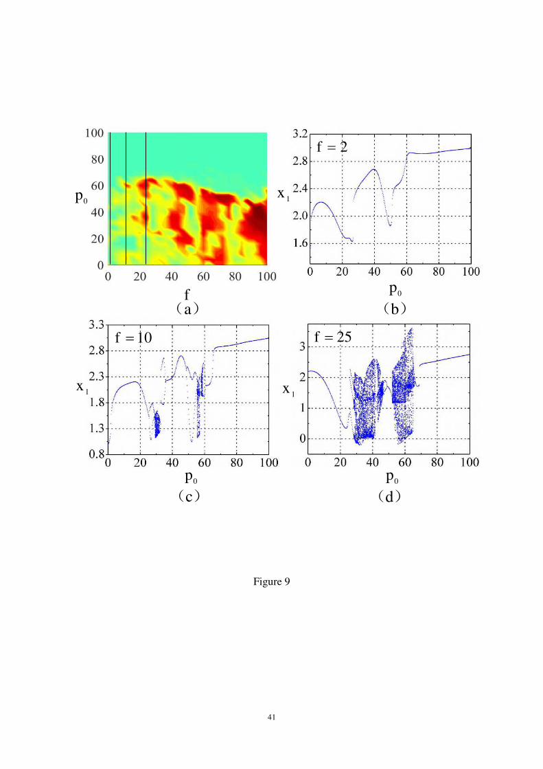
The evolution paths of the dual-parameter chaotic vibrations are studied in Figure 9
when 0p is located in the interval 1000, . Choosing the aerodynamic force
0p as the
controlling parameter, the effect of the perturbation rotating speed f on the dynamics of
the blisk is analyzed. Figure 9(a) presents the dual parameter Lyapunov exponents.
Figures 9(b)-9(d) depict three bifurcation diagrams when the perturbation rotating speeds
are 2f , 10f and 25f . As the perturbation rotating speeds f increase, the
periodic vibration of the blisk turns to the chaotic vibrations gradually, as shown in
Figures 9(b)-9(d). When 2f , the points of the bifurcation diagram in Figure 9(b) is
sparse, which means that the blisk only has the periodic vibration. When 10f , the
intensive points appear in Figure 9(c), which implies that the chaotic vibrations arise in the
blisk. When f increases to 25f , the intensive points occupy the larger range, which
means that the chaotic vibrations occur in a wider interval of the aerodynamic force 0p ,
as shown in Figure 9(d). The amplitudes of the chaotic vibrations increase. Moreover, the
larger the rotating speed is, the larger the amplitude of the chaotic vibrations is. The results
indicate that the perturbation rotating speed f decides whether the chaotic vibrations of
the blisk occur under combined the perturbation rotating speed f and aerodynamic force
0p when 0p is in the interval 10000 -p .
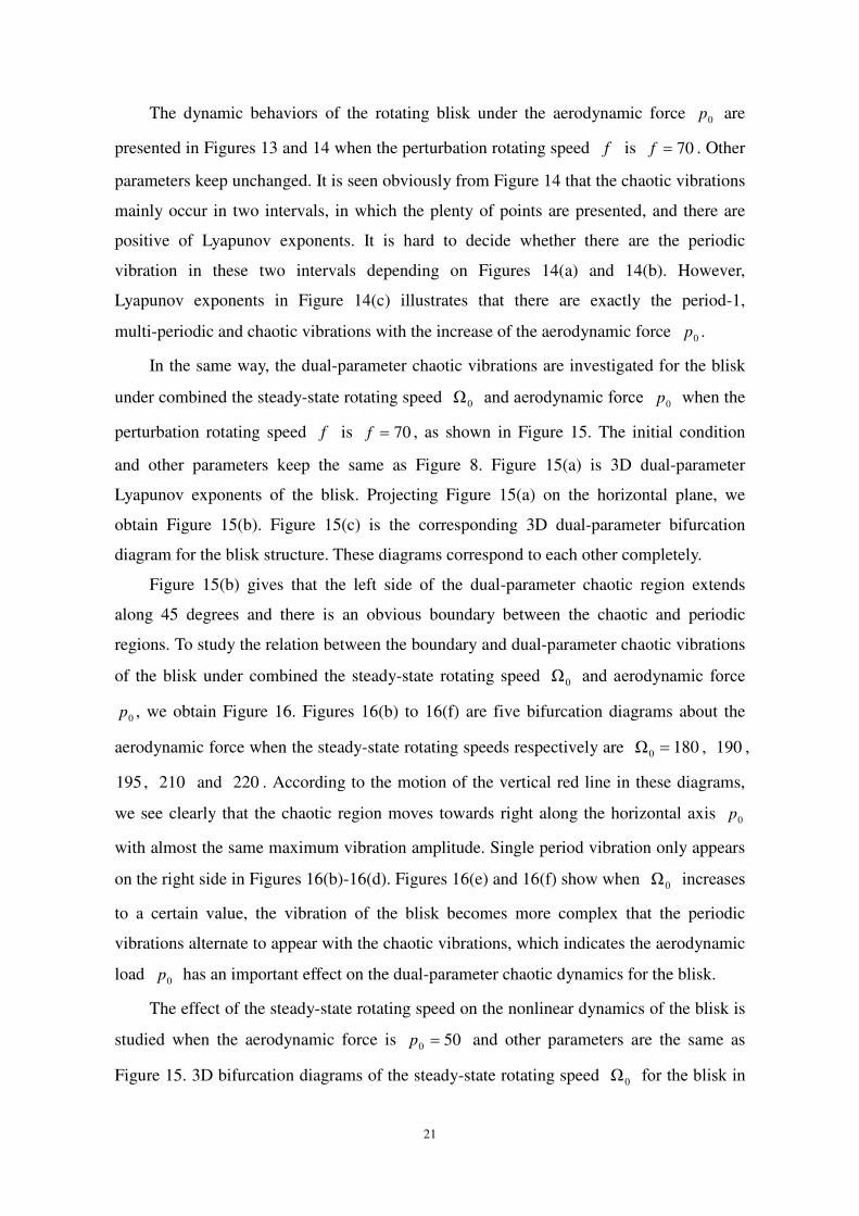
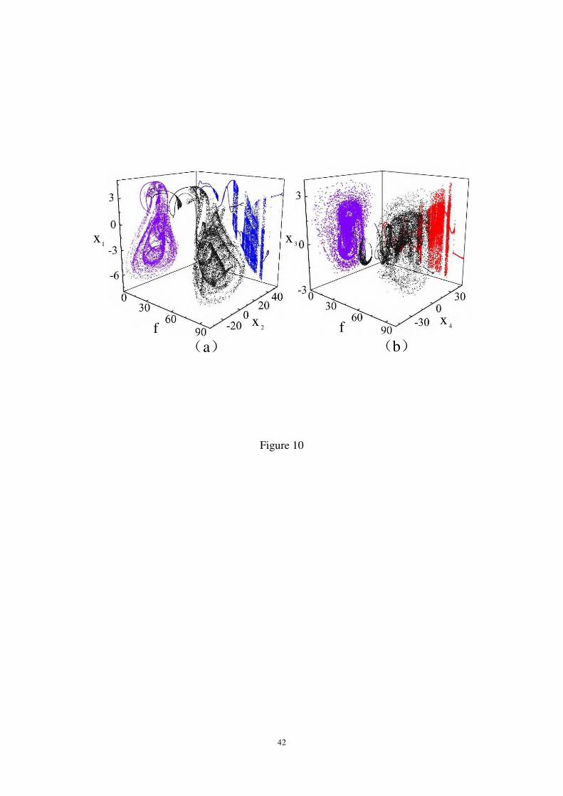
Three-dimensional bifurcation diagrams of the perturbation rotating speed f versus
the first-order and second-order modes 1x and 3x are presented in the interval
100~0f , as shown in Figure 10. Where the aerodynamic force 0p is 500 p , and
other parameters remain the same as these given in Figure 8. Projecting 3D bifurcation
20
diagram, namely, the black part in Figure 10(a), to the planes 1, xf and 21 , xx , the
two-dimensional bifurcation diagram and Poincare map are obtained. Two-dimensional
bifurcation diagram and corresponding Poincare map for the second-order mode 3x are
given, as shown in Figure 10(b). Due to figures obtained by numerical simulations, an
accurate judgment on the nonlinear vibrations of the blisk is realized.
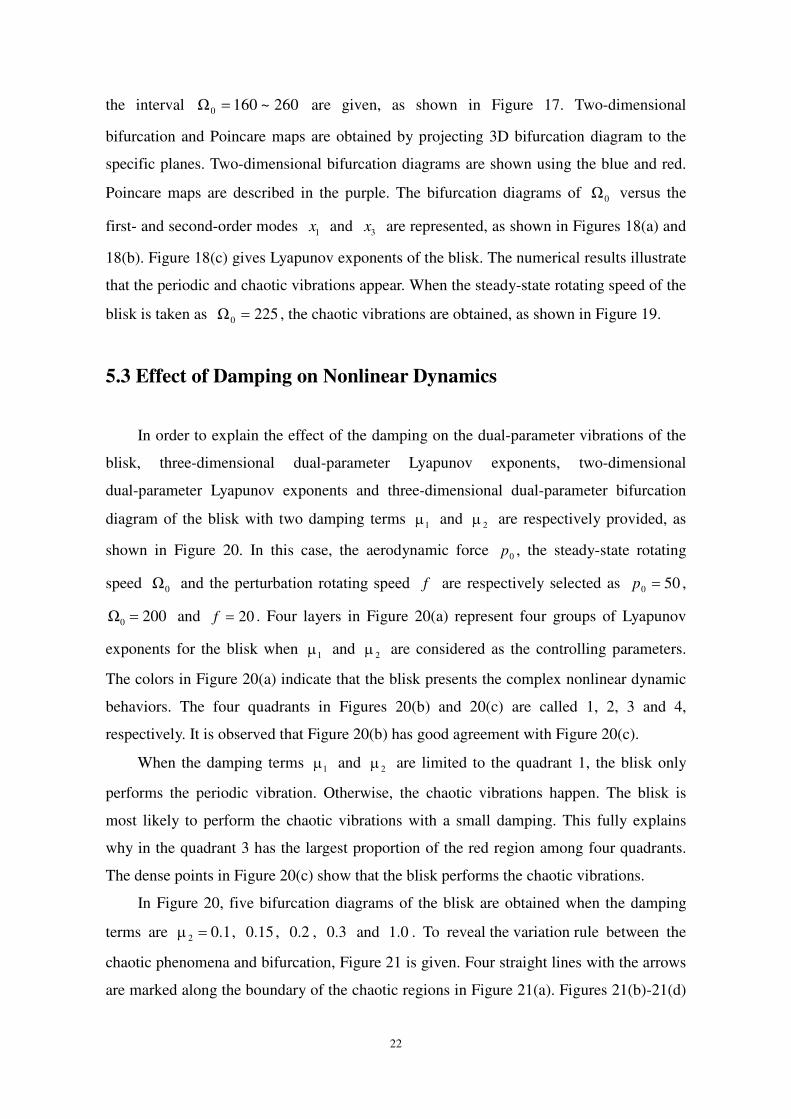
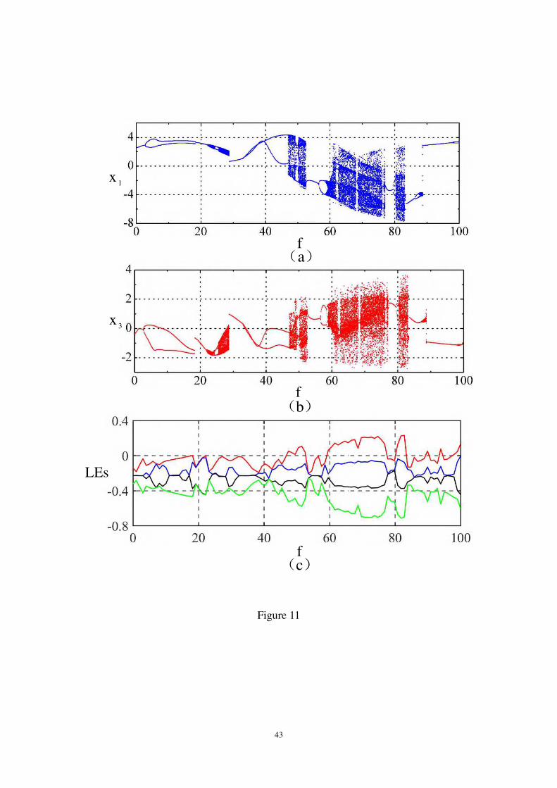
The enlarged version of the bifurcation diagrams for the perturbation rotating speed
f versus the first-order and second-order modes 1x and 3x are respectively displayed
in Figures 11(a) and 11(b). Figure 11(c) depicts Lyapunov exponents of the rotating blisk
when considering the perturbation rotating speed f as a variable. Lyapunov exponents
and bifurcation diagrams have high consistency. Lyapunov exponents generated by the
system can be positive, negative or zero. The positive Lyapunov exponents imply that the
system must be the chaotic or hyperchaotic vibrations. If a chaotic system has the multiple
positive exponents in high-dimensional phase space, it is hyperchaotic.
It is judged from Figure 11 that the periodic and chaotic vibrations of the rotating
blisk appear repeatedly. The numerical results demonstrate that the perturbation rotating
speed f has a major effect on the nonlinear dynamics of the blisk. Both negative
Lyapunov exponents in Figure 11(c) and sparse points in Figures 11(a) and 11(b) illustrate
the periodic vibrations occur in the blisk. The high density points in the interval
6528-f show that the chaotic vibrations occur, which is proved by Lyapunov
exponents in the corresponding interval in Figure 11(c). When the perturbation rotating
speed f is 72f , the max Lyapunov exponent of the blisk is positive, as shown in
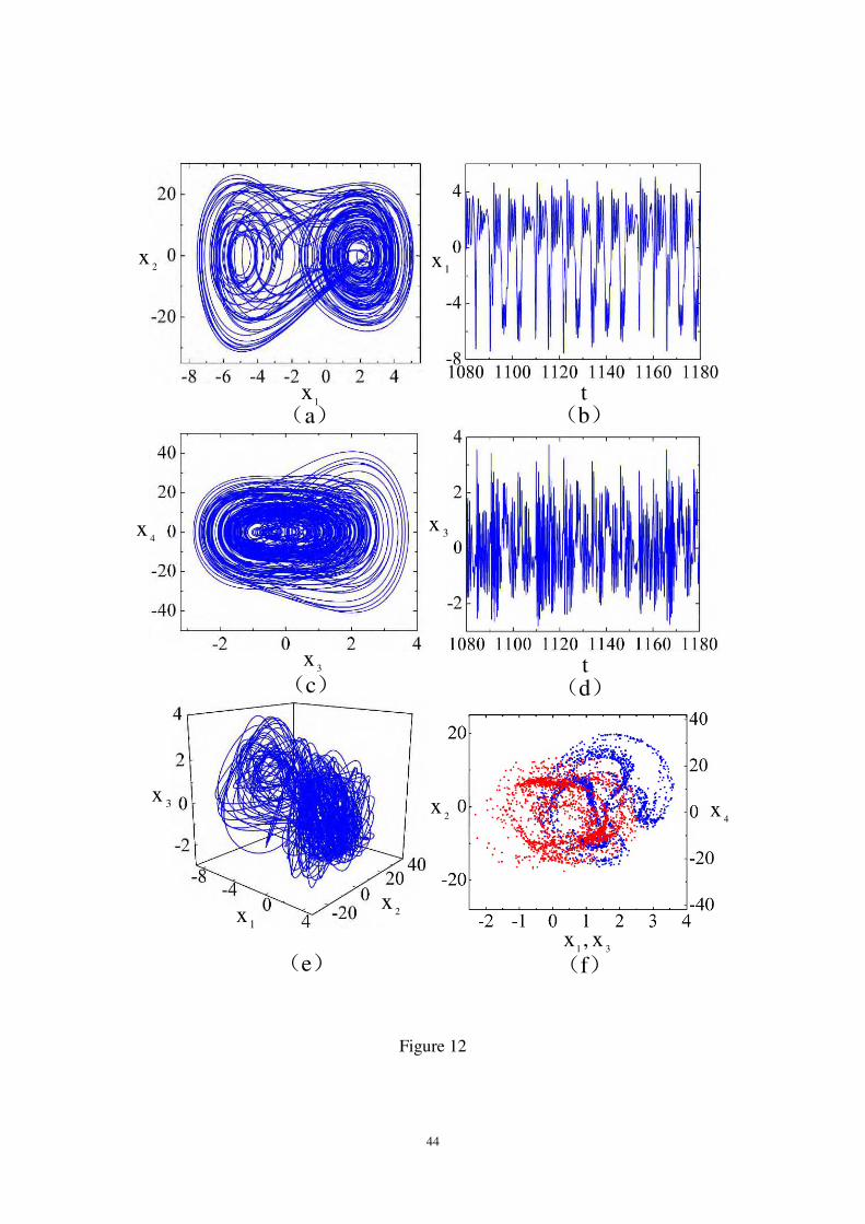
Figure 11(c). The nonlinear vibrations of the large amplitude appear when 72f , as
shown in Figure 12, which illustrates that there exist the chaotic vibrations the blisk.
Figures 12(a) and 12(c) are the phase portraits on the planes 11 , xx and 33 , xx .
Figures 12(b) and 12(d) give the waveforms on the planes 1, xt and 3, xt . Figure 12(e)
is 3D phase portrait in space 311 ,, xxx . The blue and black parts in Figure 12(f) depict
Poincare maps on the plane 11 , xx and 33 , xx . In the aforementioned analysis, the
phase portraits, waveforms and Poincare map are highly consistent.
5.2 Effects of External Excitation and Steady-State Rotating Speed
21
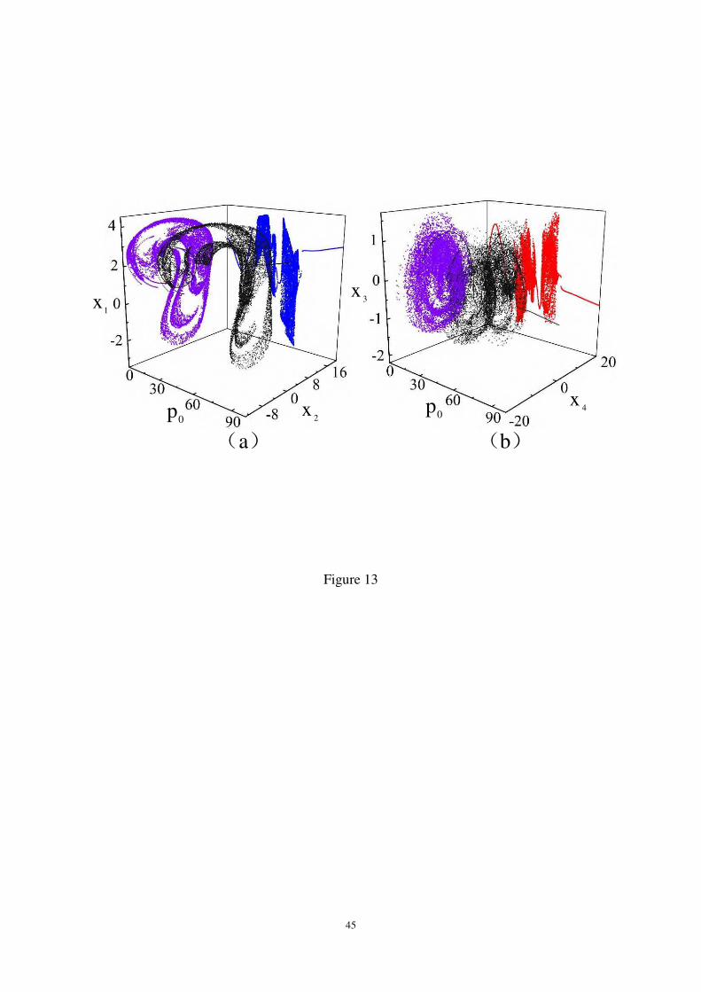
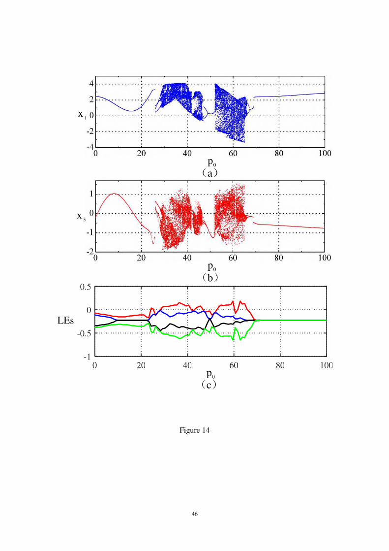
The dynamic behaviors of the rotating blisk under the aerodynamic force 0p are
presented in Figures 13 and 14 when the perturbation rotating speed f is 70f . Other
parameters keep unchanged. It is seen obviously from Figure 14 that the chaotic vibrations
mainly occur in two intervals, in which the plenty of points are presented, and there are
positive of Lyapunov exponents. It is hard to decide whether there are the periodic
vibration in these two intervals depending on Figures 14(a) and 14(b). However,
Lyapunov exponents in Figure 14(c) illustrates that there are exactly the period-1,
multi-periodic and chaotic vibrations with the increase of the aerodynamic force 0p .
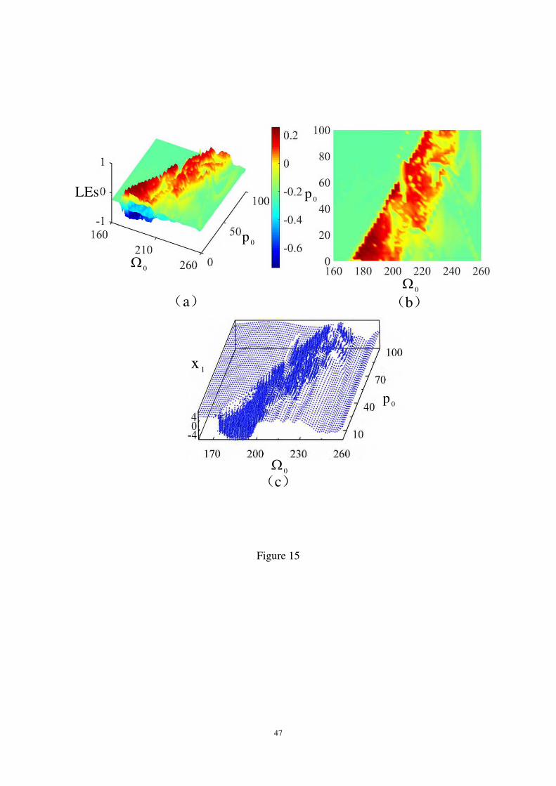
In the same way, the dual-parameter chaotic vibrations are investigated for the blisk
under combined the steady-state rotating speed 0Ω and aerodynamic force 0p when the
perturbation rotating speed f is 70f , as shown in Figure 15. The initial condition
and other parameters keep the same as Figure 8. Figure 15(a) is 3D dual-parameter
Lyapunov exponents of the blisk. Projecting Figure 15(a) on the horizontal plane, we
obtain Figure 15(b). Figure 15(c) is the corresponding 3D dual-parameter bifurcation
diagram for the blisk structure. These diagrams correspond to each other completely.
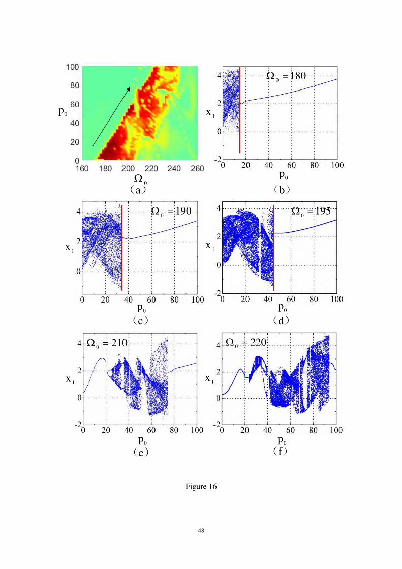
Figure 15(b) gives that the left side of the dual-parameter chaotic region extends
along 45 degrees and there is an obvious boundary between the chaotic and periodic
regions. To study the relation between the boundary and dual-parameter chaotic vibrations
of the blisk under combined the steady-state rotating speed 0Ω and aerodynamic force
0p , we obtain Figure 16. Figures 16(b) to 16(f) are five bifurcation diagrams about the
aerodynamic force when the steady-state rotating speeds respectively are 180Ω0 , 190 ,
195 , 210 and 220 . According to the motion of the vertical red line in these diagrams,
we see clearly that the chaotic region moves towards right along the horizontal axis 0p
with almost the same maximum vibration amplitude. Single period vibration only appears
on the right side in Figures 16(b)-16(d). Figures 16(e) and 16(f) show when 0Ω increases
to a certain value, the vibration of the blisk becomes more complex that the periodic
vibrations alternate to appear with the chaotic vibrations, which indicates the aerodynamic
load 0p has an important effect on the dual-parameter chaotic dynamics for the blisk.
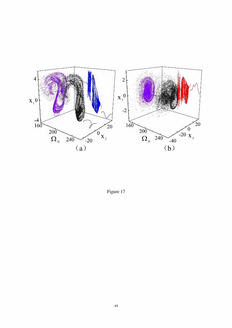
The effect of the steady-state rotating speed on the nonlinear dynamics of the blisk is
studied when the aerodynamic force is 500 p and other parameters are the same as
Figure 15. 3D bifurcation diagrams of the steady-state rotating speed 0Ω for the blisk in
22
the interval 260~160Ω0 are given, as shown in Figure 17. Two-dimensional
bifurcation and Poincare maps are obtained by projecting 3D bifurcation diagram to the
specific planes. Two-dimensional bifurcation diagrams are shown using the blue and red.
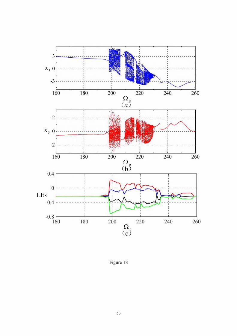
Poincare maps are described in the purple. The bifurcation diagrams of 0Ω versus the
first- and second-order modes 1x and 3x are represented, as shown in Figures 18(a) and
18(b). Figure 18(c) gives Lyapunov exponents of the blisk. The numerical results illustrate
that the periodic and chaotic vibrations appear. When the steady-state rotating speed of the
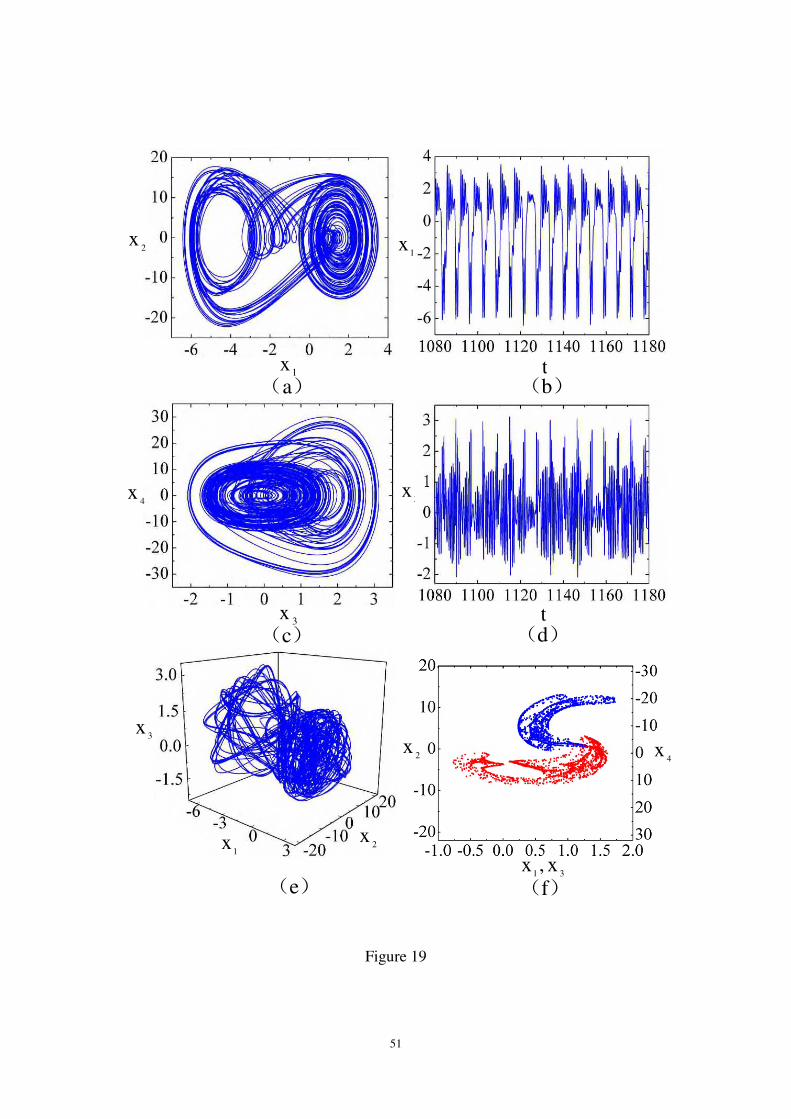
blisk is taken as 225Ω0 , the chaotic vibrations are obtained, as shown in Figure 19.
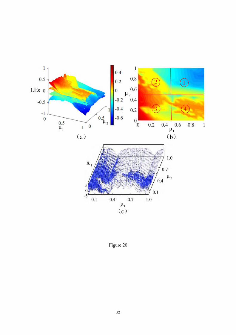
5.3 Effect of Damping on Nonlinear Dynamics
In order to explain the effect of the damping on the dual-parameter vibrations of the
blisk, three-dimensional dual-parameter Lyapunov exponents, two-dimensional
dual-parameter Lyapunov exponents and three-dimensional dual-parameter bifurcation
diagram of the blisk with two damping terms 1 and
2 are respectively provided, as
shown in Figure 20. In this case, the aerodynamic force 0p , the steady-state rotating
speed 0Ω and the perturbation rotating speed f are respectively selected as 500 p ,
200Ω0 and 20f . Four layers in Figure 20(a) represent four groups of Lyapunov
exponents for the blisk when 1 and
2 are considered as the controlling parameters.
The colors in Figure 20(a) indicate that the blisk presents the complex nonlinear dynamic
behaviors. The four quadrants in Figures 20(b) and 20(c) are called 1, 2, 3 and 4,
respectively. It is observed that Figure 20(b) has good agreement with Figure 20(c).
When the damping terms 1 and
2 are limited to the quadrant 1, the blisk only
performs the periodic vibration. Otherwise, the chaotic vibrations happen. The blisk is
most likely to perform the chaotic vibrations with a small damping. This fully explains
why in the quadrant 3 has the largest proportion of the red region among four quadrants.
The dense points in Figure 20(c) show that the blisk performs the chaotic vibrations.
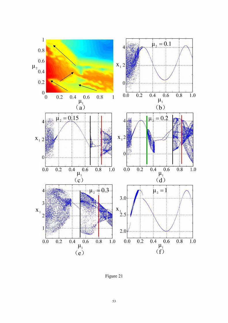
In Figure 20, five bifurcation diagrams of the blisk are obtained when the damping
terms are 1.02 , 15.0 , 2.0 , 3.0 and 0.1 . To reveal the variation rule between the
chaotic phenomena and bifurcation, Figure 21 is given. Four straight lines with the arrows
are marked along the boundary of the chaotic regions in Figure 21(a). Figures 21(b)-21(d)
23
demonstrate that the chaotic regions moves to the left as 2 increases in a certain range.
The nonlinear vibrations of the blisk give the regular changes: period-1 multi-periodic
chaotic vibrations when 1 is selected in the interval between the red and black lines.
There exist also the period-2, multi-periodic and chaotic vibrations in the region between
the green and black lines in Figure 21(d). With 2 becomes larger in the quadrants 3 and
4, the nonlinear vibrations of the blisk become more and more diversification. The
periodic vibrations occupy a wider interval 1 , which means that the blisk is less likely to
perform the large amplitude nonlinear vibrations when 2 is large enough.
The influences of the damping 1 on the nonlinear vibrations of the blisk are
presented, as shown in Figure 22. The bifurcation diagrams and Lyapunov exponents of
the blisk are depicted. The damping 2 is 46.02 . Other parameters are as same as
Figure 20. It is found that the dynamic responses of the blisk exhibit the following
evolution law: chaotic periodic vibrations, with the increase of the damping 1 . It is
seen that the periodic vibration happens when the damping 1 increases to 44.01 .
The damping 1 has significantly effect on the nonlinear dynamics of the blisk.
6. Conclusions
The dual-parameter chaotic vibrations of the lumped parameter model for the rotating
blisk are studied under combined the varying rotating speed and aerodynamic force. The
free vibration and mode localization phenomenon of the lumped parameter model are
investigated for the tuning and detuning blisk structure. The nonlinear dynamic model of
the rotating blisk subjected to the aerodynamic force is presented by using Hamilton’s
principle. The amplitude-frequency response curves are obtained by applying the method
of multiple scales under 1:1 internal resonance and principal parametric resonance. The
evolution process to the chaotic vibrations for the rotating blisk is described by the
dual-parameter Lyapunov exponents and bifurcation diagrams. The influences of different
parameters on the nonlinear responses of the blisk are analyzed based on the amplitude
frequency response curves of the first two modes. The main conclusions are obtained.
(1) Comparing with the mode shapes of the tuning blades, the mode shapes of the
mass detuning or stiffness detuning blades are not sinusoidal. There is a positive
correlation between the mistuning variable and mode localization factor. The larger the
24
mode localization factor is, the more irregular the mode shape becomes. The large
amplitude vibrations appear in a certain part and lead to the chaotic vibrations of the blisk.
(2) Some parameters seriously affect the vibration amplitudes, response bandwidths
and stiffness properties of the blisk. The spring property of the blisk remains unchanged
when the perturbation rotating speed, coupling stiffness and aerodynamic force are
changed. The nonlinear terms determine the spring property of the blisk. If it is positive,
the blisk shows the hard spring property. When it becomes negative, the blisk presents the
soft spring property. The corresponding amplitude-frequency curves are perfectly
symmetrical about the longitudinal axis as the values of the nonlinear term are opposite.
(3) The dual-parameter Lyapunov exponents and bifurcation diagrams of the blisk
illustrate that the evolution paths leading to the chaotic vibrations and varying pattern of
the chaotic regions are determined three different parameters of the blisk, including the
rotating speed, aerodynamic force and damping.
(4) The phase portraits, waveforms and Poincare maps are depicted to verify the
nonlinear dynamic behaviors of the blisk according to the dual-parameter Lyapunov
exponents and bifurcation diagrams when one of the controlling parameters is constant.
The aforementioned conclusions indicate that chaotic vibrations are closely related to
the comprehensive effect of the various factors for the blisk. Due to the small damping and
approximate stiffness of the disk and blade, the large amplitude coupling vibrations of the
blisk are more likely to occur, and even cause a disaster. Thus, our studies have the
practical significance for the nonlinear vibration control of the blisk.
Acknowledgments
The authors gratefully acknowledge the support of National Natural Science
Foundation of China (NNSFC) through grant Nos.11832002, 12072201 and 11427801, the
Funding Project for Academic Human Resources Development in Institutions of Higher
Learning under the Jurisdiction of Beijing Municipality (PHRIHLB) and the funding
received from the University of Toronto Advanced Research Laboratory for
Multifunctional Lightweight Structures (ARL-MLS).
Conflicts of Interest
25
The authors declare that there is no conflict of interests regarding the publication of
this paper.
Data Availability Statement
All data generated or analysed during this study are included in this published article.
References
[1] Z. J. Li, W. J. Yang and H. Q. Yuan, Vibration analysis of aeroengine blisk structure
based on a prestressed CMS super-element method, Shock and Vibration, 1021402,
2016.
[2] L. T. Liu, Y. X. Hao, W. Zhang and J. Chen, Free vibration analysis of rotating
pretwisted functionally graded sandwich blades, International Journal of Aerospace
Engineering, 2727452, 2018.
[3] Y. Niu, W. Zhang and X. Y. Guo, Free vibration of rotating pretwisted functionally
graded composite cylindrical panel reinforced with graphene platelets, European
Journal of Mechanics A-Solids 77, 103798, 2019.
[4] F. X. Wang and W. Zhang, Stability analysis of a nonlinear rotating blade with
torsional vibrations, Journal of Sound and Vibration 331, p5755-5773, 2012.
[5] Y. X. Hao, Y. Niu, W. Zhang, S. B. Li, M. H. Yao and A. W. Wang, Supersonic flutter
analysis of FGM shallow conical panel accounting for thermal effects, Meccanica 53,
p95-109, 2018.
[6] R. Q. Wu, W. Zhang and M. H. Yao, Nonlinear dynamics near resonances of a
rotor-active magnetic bearings system with 16-pole legs and time varying stiffness,
Mechanical Systems and Signal Processing 100, p113-134, 2018.
[7] M. H. Yao, Y. Niu and Y. X. Hao, Nonlinear dynamic responses of rotating pretwisted
cylindrical shells, Nonlinear Dynamics 95, p151-174, 2019.
[8] B. L. Hao, An overview of chaos, Recent Advances and Cross-Century Outlooks in
Physics: Interplay between Theory and Experiment, p285-294, 2000.
[9] X. J. Jing and A. F. Vakakis, Exploring nonlinear benefits in engineering, Mechanical
systems and Signal Processing 125, p1-3, 2019.
[10] M. H. Yao, Y. P. Chen and W. Zhang, Nonlinear vibrations of blade with varying
26
rotating speed, Nonlinear Dynamics 68, p487-504, 2012.
[11] X. H. Zhang, F. Q. Chen, B. Q. Zhang and T. Y. Jing, Local bifurcation analysis of a
rotating blade, Applied Mathematical Modelling 40, p4023-4031, 2016.
[12] Y. Wang, F. M. Li, Y. Z. Wang and X. J. Jing, Nonlinear responses and stability
analysis of viscoelastic nanoplate resting on elastic matrix under 3:1 internal
resonance, International Journal of Mechanical Sciences 128, p94-104, 2017.
[13] C. F. Li, H. X. She, Q. S. Tang and B. C. Wen, The effect of blade vibration on the
nonlinear characteristics of rotor-bearing system supported by nonlinear suspension,
Nonlinear Dynamics 89, p987-1010, 2017.
[14] M. H. Yao, L. Ma and W. Zhang, Nonlinear dynamics of the high-speed rotating plate,
International Journal of Aerospace Engineering 5610915, 2018.
[15] Y. Wang and X. J. Jing, Nonlinear stiffness and dynamical response characteristics of
an asymmetric X-shaped structure, Mechanical Systems and Signal Processing 125,
p142-169, 2019.
[16] D. X. Cao, B. Y. Liu, M. H. Yao and W. Zhang, Free vibration analysis of a
pre-twisted sandwich blade with thermal barrier coatings layers, Science
China-Technological Sciences 60, p1747-1761, 2017.
[17] E. H. Dowell, R. Clark, D. Cox, H. C. Curtiss, J. W. Edwards, K. C. Hall, D. A.
Peters, R. Scanlan, E. Simiu, F. Sisto, T. W. Strgance, A modern course in
aeroelasticity, Aviation Industry Press, Beijing, p331-348, 2014.
[18] H. Y. Zhang, H. Q. Yuan, W. J. Yang and T. Y. Zhao, Vibration reduction optimization
of the mistuned bladed disk considering the prestress, Proceedings of the Institution
of Mechanical Engineers Part G-Journal of Aerospace Engineering 233, p226-239,
2019.
[19] B. Bai, H. Li, W. Zhang and Y. C. Cui, Application of extremum response surface
method-based improved substructure component modal synthesis in mistuned turbine
bladed disk, Journal of Sound and Vibration 472, 115210, 2020.
[20] H. Ma, X. Y. Tai, Q. K. Han, Z. Y. Wu, D. Wang and B. C. Wen, A revised model for
rubbing between rotating blade and elastic casing, Journal of Sound and Vibration
337, p301-320, 2015.
[21] Z. X. Yang, Q. K. Han, Y. G. Chen and Z. H. Jin, Nonlinear harmonic response
characteristics and experimental investigation of cantilever hard-coating plate,
Nonlinear Dynamics 89, p27-38, 2017.
[22] F. Gao and W. Sun, Nonlinear finite element modeling and vibration analysis of the
27
blisk deposited strain-dependent hard coating, Mechanical Systems and Signal
Processing 121, p124-143, 2019.
[23] J. Nipkau, A. Kühhorn, and B. Beirow, Modal and aeroelastic analysis of a
compressor blisk considering mistuning, ASME 2011 Turbo Expo: Turbine
Technical Conference and Exposition, p1309-1319, 2011.
[24] M. Mitra, S. Zucca and B. I. Epureanu, Dynamic model order reduction of blisks with
nonlinear damping coatings using amplitude dependent mistuning, International
Journal of Non-Linear Mechanics 111, p49-59, 2019.
[25] A. Chatterjee, Lumped parameter modelling of turbine blade packets for analysis of
modal characteristics and identification of damage induced mistuning, Applied
Mathematical Modelling 40, p2119-2133, 2016.
[26] W. Zhang, S. L. Lv and Y. G. Ni, Parametric aeroelastic modeling based on
component modal synthesis and stability analysis for horizontally folding wing with
hinge joints, Nonlinear Dynamics 92, p169-179, 2018.
[27] H. W. Ning and X. J. Jing, Identification of partially known non-linear stochastic
spatio-temporal dynamical systems by using a novel partially linear Kernel method,
IET Control Theory & Applications 9, p21-33, 2015.
[28] J. Yuan, G. Allegri, F. Scarpa, F. Scarpa, R. Rajasekaran and S. P,atsias. Novel
parametric reduced order model for aeroengine blade dynamics, Mechanical Systems
and Signal Processing 62-63, p235-253, 2015.
[29] W. H. Tang and B. I. Epureanu, Nonlinear dynamics of mistuned bladed disks with
ring dampers, International Journal of Non-Linear Mechanics 97, p30-40, 2017.
[30] M. Mitra, S. Zucca and B. I. Epureanu, Adaptive Microslip Projection for Reduction
of Frictional and Contact Nonlinearities in Shrouded Blisks, Journal of
Computational and Nonlinear Dynamics 11, 041016, 2016,
[31] W. Sun, R. Li and J. X. Jiang, Lumped-parametric modeling based on modal test and
analysis of vibration characteristics of the hard-coated blisk, Journal of Vibration
Engineering and Technologies 7, p347-358, 2019.
[32] F. Gao and W. Sun, Free vibration analysis of the hard-coating splitter blisk using the
energy-based finite element method, Proceedings of the Institution of Mechanical
Engineers Part C-Journal of Mechanical Engineering Science 233, p4577-4589,
2019.
[33] W. Zhang, Y. Niu and K. Behdinan, Vibration characteristics of rotating pretwisted
composite tapered blade with graphene coating layers, Aerospace Science and
28
Technology 98, 105644, 2020.
[34] W. Zhang, Y. Zheng, T. Liu and X. Y. Guo, Multi-pulse jumping double-parameter
chaotic dynamics of eccentric rotating ring truss antenna under combined parametric
and external excitations, Nonlinear Dynamics 98, p761-800, 2019.
[35] M. G. Salas, P. Petrierepar, H. Martensson, R. Bladh and D. M. Vogt, Forced
response analysis of a mistuned blisk using noncyclic reduced-order models, Journal
of Propulsion and Power 34, p565-577, 2018.
[36] X. F. Yan, J. N. Gao, Y. Zhang, K. P. Xu and W. Sun, Modeling method of coating
thickness random mistuning and its effect on the forced response of coated blisks,
Aerospace Science and Technology 92, p478-488, 2019.
[37] Y. Han and M. P. Mignolet, A novel perturbation-based approach for the prediction of
the forced response of damped mistuned bladed disks, Journal of Vibration and
Acoustics-Transactions of the ASME 137, 041008, 2015.
[38] S. Willeke, L. Schwerdt, L. Panning-von Scheidt and J. Wallaschek, Intentional
response reduction by harmonic mistuning of bladed disks with aerodynamic
damping, Journal of Engineering for Gas Turbines and Power 140, 121010, 2018.
[39] F. Gao, W. Sun and L. Jiang, Application of the hard-coating damper on the mistuned
blisk for passive vibration reduction, Proceedings of the Institution of Mechanical
Engineers Part C-Journal of Mechanical Engineering Science 233, p1562-1574,
2019.
[40] Y. G. Chen, H. C. Wu, J. Y. Zhai, H. Chen, Q. Y. Zhu and Q. K. Han, Vibration
reduction of the blisk by damping hard coating and its intentional mistuning design,
Aerospace Science and Technology 84, p1049-1058, 2019.
[41] X. Feng and X. J. Jing, Human body inspired vibration isolation: beneficial nonlinear
stiffness, nonlinear damping & nonlinear inertia, Mechanical Systems and Signal
Processing 117, p786-812, 2019.
[42] D. Laxalde, F. Thouverez, J. J. Sinou and J. P. Lombard, Qualitative analysis of
forced response of blisks with friction ring dampers, European Journal of Mechanics
A-Solids 26, p676-687, 2007.
[43] M. G. Salas, P. Petrie-Repar, R. E. Kielb and N. L. Key, A mistuned forced response
analysis of an embedded compressor blisk using a reduced-order model, Journal of
Engineering for Gas Turbines and Power- ASME 141, 032505, 2019.
[44] B. Beirow, A. Kuhhorn, T. Giersch and J. Nipkau, Forced response analysis of a
mistuned compressor blisk, Proceedings of the ASME Turbo Expo: Turbine
29
Technical Conference and Exposition 136, 062507, 2014.
[45] E. Sarrouy, A. Grolet, and F. Thouverez, Global and bifurcation analysis of a
structure with cyclic symmetry, International Journal of Non-Linear Mechanics 46,
p727-737, 2011.
[46] L. Hoskoti, A. Misra and M. M. Sucheendran, Frequency lock-in during vortex
induced vibration of a rotating blade, Journal of Fluids and Structures 80, p145-164,
2018.
[47] X. J. Gu, Y. X. Hao, W. Zhang, L. T. Liu and J. Chen, Free vibration of rotating
cantilever pre-twisted panel with initial exponential function type geometric
imperfection, Applied Mathematical Modelling 68, p327-352, 2019.
[48] A. Najafi, The stability and nonlinear analysis of a rotating bladed disk at the critical
speed, Archive of Applied Mechanics 88, p405-418, 2018.
[49] P. C. Deng, L. Li and C. Li, Study on vibration of mistuned bladed disk with
bi-periodic piezoelectric network, Proceedings of the Institution of Mechanical
Engineers Part G-Journal of Aerospace Engineering 231, p350-363, 2017.
[50] N. Jamia, P. Rajendran, S. El-Borgi and M. I. Friswell, Mistuning identification in a
bladed disk using wavelet packet transform, Acta Mechanica 229, p1275-1295, 2018.
[51] Y. Wang, X. J. Jing, H. H. Dai and F. M. Li, Subharmonics and ultra-subharmonics of
a bio-inspired nonlinear isolation system, International Journal of Mechanical
Sciences 152, p167-184, 2019.
[52] S. Lee, M. Castanier and C. Pierre, Assessment of probabilistic methods for mistuned
bladed disk vibration, 46th AIAA/ASME/ASCE/AHS/ASC Structures, Structural
Dynamics and Materials Conference, Texas, 2005.
[53] M. H. Yao, W. Zhang and Y. P. Chen, Analysis on nonlinear oscillations and resonant
responses of a compressor blade, Acta Mechanica 225, p3483-3510, 2014.
30
Figure Captions
Figure 1 The lumped parameter model of the rotating blisk is given by considering the
phase angle, (a) lumped parameter model of blisk, (b) rotating Cartesian
coordinate system of blisk.
Figure 2 The first fifteen modals of the blades are obtained for the tuning blisk.
Figure 3 The first fifteen vibration modes of the blades are given with the mass
mistuning, where the change of the mistuned mass for the blades is %2 .
Figure 4 The natural frequencies of the blisk are obtained without mistuning and with
mistuning conditions, (a) influence of masses without mistuning and with
mistuning when 0 , %1 , %3 and %5 , (b) influence of
stiffness terms without mistuning and with mistuning when 0 , %1 ,
%3 and %5 .
Figure 5 The mode localization factors of the blisk are obtained without mistuning and
with mistuning conditions, (a) influence of masses without mistuning and with
mistuning when 0 , %1 , %3 and %5 , (b) influence of
stiffness terms without mistuning and with mistuning when 0 , %1 ,
%3 and %5 .
Figure 6 The amplitude-frequency response curves are obtained for the blades, (a)
influence of damping, (b) influence of amplitude of perturbation rotating speed,
(c) influence of coupling stiffness parameter, (d) influence of aerodynamic
force, (e) influence of cubic term.
Figure 7 The amplitude-frequency response curves are obtained for the disk, (a)
influence of damping, (b) influence of perturbation rotating speed, (c)
influence of coupling stiffness parameter.
Figure 8 The dual-parameter Lyapunov exponents and bifurcation diagram versus f
and 0p are obtained, (a) 3D dual-parameter Lyapunov exponents, (b)
projection of dual-parameter Lyapunov exponents diagram on plane ),( 0pf ,
(c) dual-parameter bifurcation diagram on space ),,( 10 xpf .
Figure 9 The dual-parameter Lyapunov exponents and three bifurcation diagrams with
f as control parameter are given, (a) dual-parameter Lyapunov exponents on
plane ),( 0pf , (b) bifurcation diagram when 2f , (b) bifurcation diagram
31
when 10f , (b) bifurcation diagram when 25f .
Figure 10 3D bifurcation diagrams of the perturbation rotating speed for the blisk are
given in the interval 100~0f , (a) 3D bifurcation diagram in space
),,( 21 fxx , (b) 3D bifurcation diagram in space ),,( 43 fxx .
Figure 11 The bifurcation diagrams and Lyapunov exponents of the perturbation rotating
speed for the blisk are given in interval 100~0f , (a) bifurcation diagram
on plane ),( 1 fx ; (b) bifurcation diagram on plane ),( 3 fx , (c) Lyapunov
exponents.
Figure 12 The chaotic vibrations of the lumped parameter model are studied for the blisk
when 72f , (a) phase portrait on plane ),x( 21 x , (b) waveform on plane
),( 1xt , (c) phase portrait on plane ),x( 43 x ; (d) waveform on plane ),( 3xt ,
(e) 3D phase portrait in space ),,x( 321 xx ; (f) Poincare map.
Figure 13 3D bifurcation diagrams of the external excitation for the blisk are given in the
interval 100~00 p , (a) 3D bifurcation diagram in space ),,( 021 pxx , (b)
3D bifurcation diagram on space ),,( 043 pxx .
Figure 14 The bifurcation diagrams and Lyapunov exponents of the external excitation are
given in the interval 100~00 p , (a) bifurcation diagram on plane ),( 01 px ,
(b) bifurcation diagram on plane ),( 03 px , (c) Lyapunov exponents.
Figure 15 The dual-parameter Lyapunov exponents and bifurcation diagrams of 0 and
0p are obtained, (a) dual-parameter Lyapunov exponents on space
)LEs,,( 00 p , (b) projection of dual-parameter Lyapunov exponents on plane
),( 00 p , (c) dual-parameter bifurcation diagram on space ),,( 100 xp .
Figure 16 The dual-parameter Lyapunov exponents and five bifurcation diagrams are
given with 0 as the control parameter, (a) dual-parameter Lyapunov
exponents on plane ),( 00 p , (b) bifurcation diagram on plane ),( 10 xp
when 180Ω0 , (c) bifurcation diagram on plane ),( 10 xp when 190Ω0 ,
(d) bifurcation diagram on plane ),( 10 xp when 220Ω0 , (e) bifurcation
diagram on plane ),( 10 xp when 195Ω0 , (f) bifurcation diagram on plane
),( 10 xp when 210Ω0 .
32
Figure 17 3D bifurcation diagrams of the steady-state rotating speed for the blisk are given
in the interval 260~1600 , (a) 3D bifurcation diagram on space
),,( 021 xx , (b) 3D bifurcation diagram on space ),,( 043 xx .
Figure 18 The bifurcation diagrams and Lyapunov exponents of the steady-state rotating
speed for the blisk are given in the interval 260~1600 , (a) bifurcation
diagram on plane ),( 01 x , (b) bifurcation diagram on plane ),( 03 x , (c)
Lyapunov exponents.
Figure 19 The chaotic vibrations of the lumped parameter model for the rotating blisk are
studied when 2250 , (a) phase portrait on plane ),( 11 xx , (b) waveform
on plane ),( 1xt , (c) phase portrait on plane ),( 33 xx , (d) waveform on plane
),( 3xt , (e) 3D phase portrait in space ),,x( 321 xx , (f) Poincare map.
Figure 20 The dual-parameter Lyapunov exponents and bifurcation diagrams of 1 and
2 are given for the blisk, (a) dual-parameter Lyapunov exponents on space
)LEs,,( 21 , (b) projection of dual-parameter Lyapunov exponents on plane
),( 21 , (c) dual-parameter bifurcation diagram on space ),,( 121 x .
Figure 21 The dual-parameter Lyapunov exponents and five bifurcation diagrams are
obtained for the blisk with the damping 2 as the control parameter, (a)
dual-parameter Lyapunov exponents on plane ),( 21 , (b) bifurcation
diagram on plane ),( 11 x when 0.1μ 2 , (c) bifurcation diagram on plane
),( 11 x when 0.15μ 2 , (d) bifurcation diagram on plane ),( 11 x when
0.2μ2 , (e) bifurcation diagram on plane ),( 11 x when 0.3μ 2 , (f)
bifurcation diagram on plane ),( 11 x when 1.0μ 2 .
Figure 22 3D bifurcation diagrams of the damping are given for the blisk in the interval
1~01 , (a) 3D bifurcation diagram in space ),,( 121 xx , (b) 3D
bifurcation diagram in space ),,( 143 xx .
33
Figure 1
i
j
o
)(b
)(a
34
Figure 2
mode7th
n
modest1
nmode4th
n
mode10th
nmode13th
n
mode8th
n
mode2nd
nmode5th
n
mode11th
nmode14th
n
mode9th
n
moderd3
n
mode6th
n
mode12th
nmode15th
n
35
Figure 3
mode13th
n
mode7th
n
mode10th
n
modest1
n
mode4th
n
mode14th
n
mode8th
n
mode11th
n
mode2nd
n
mode5th
n
mode15th
n
mode9th
n
mode12th
n
moderd3
n
mode6th
n
36
Figure 4
)(b
)(a
37
Figure 5
)(b
)(a
38
Figure 6
1
1a
082.015 a
082.015 a
2.015 a2.015 a5.015 a5.015 a
)(e
)(b)(a
20f
30f
10f
1
1a
5.01
9.01
2.01
1
1a
)(c )(d
3k12
5.1k12 1k12
1
1a
1
1a
4p1 6p1 5p1
39
Figure 7
)(c
2k 21
4k 21
6k 21
2
2a
2
2.02 5.02
2a8.02
)(b)(a2
2a
10f 12f
5f
40
Figure 8
)(b)(af
f
0p
LEs0
p
)(c
0p
f
1x
41
Figure 9
f
0p
2f
1x
0p
0p
1x
0p
1x
25f 10f
)(b
)(c )(d
)(a
42
Figure 10
)(a
f 2x
1x
)(b
f 4x
3x
43
Figure 11
)(c
LEs
f
)(b
3x
f
)(a
1x
f
44
Figure 12
)(b)(at
1x2
x
1x
)(c )(d
3x
t
4x
3x
)(e
4x
)(f
2x
31x,x
3x
1x 2
x
45
Figure 13
2x
1x
0p 4
x
3x
0p
)(b)(a
46
Figure 14
)(a0
p
1x
)(b0
p
3x
)(c
0 20 40 60 80 100-1
-0.5
0
0.5
0p
LEs
47
Figure 15
)(b)(a0
0p
0
0p
LEs
)(c
1x
0
0p
48
Figure 16
1800
0p
0p
0
1x
)(b)(a
1900
0p
1x
1950
1x
0p
)(c )(d
2200
1x
0p
2100
0p
1x
)(e )(f
49
Figure 17
)(b)(a0
2x
1x
0 4
x
3x
50
Figure 18
0
1x
0
3x
0
LEs
)(b
)(a
)(c
51
Figure 19
3x
)(b)(a
)(c )(d
1x t
3x t
2x
4x
1x
)(e )(f
2x
4x
31x,x
2x
1x
3x
52
Figure 20
1μ
12
43
2μ
2μ1
μ
LEs
)(b)(a
)(c1
μ
2μ
1x
53
Figure 21
)(b)(a
1x
1μ
0.1μ2
2μ
1μ
)(c )(d
1x
1μ
0.15μ2
1x
1μ
0.2μ2
)(e
1x
1μ
0.3μ2
)(f1
μ
1μ2
1x
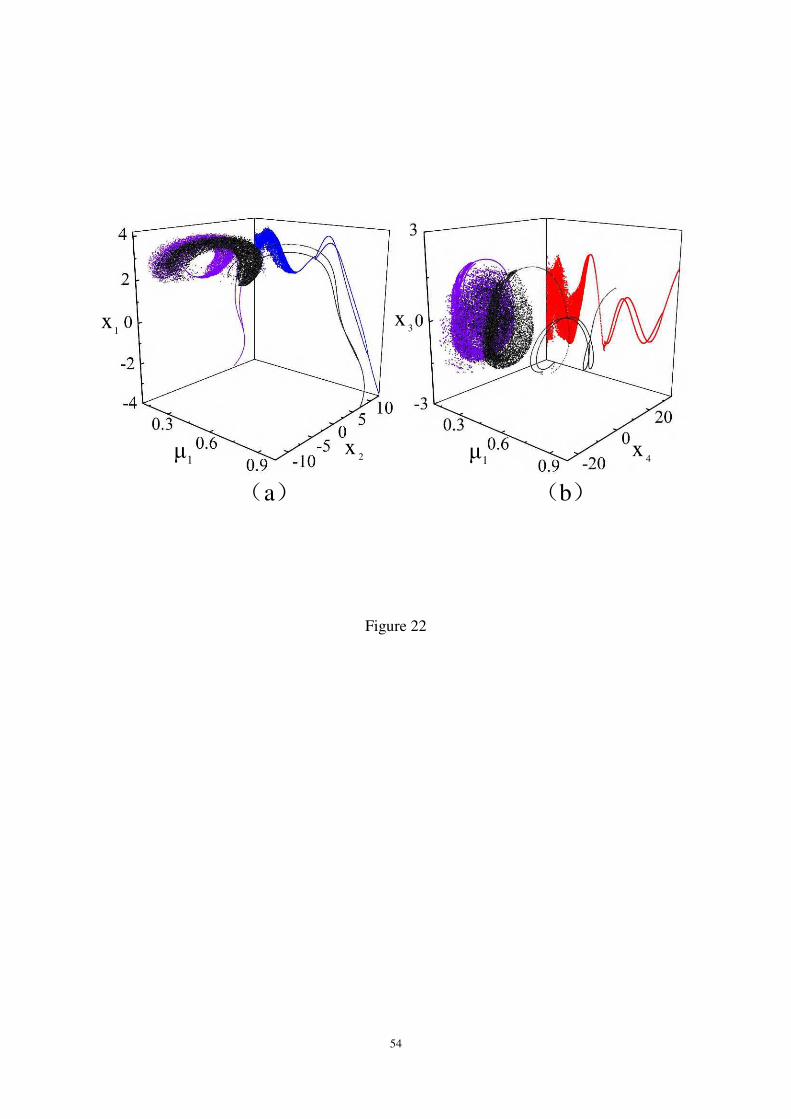
54
Figure 22
)(b)(a
1μ 2
x
1x
1μ 4
x
3x
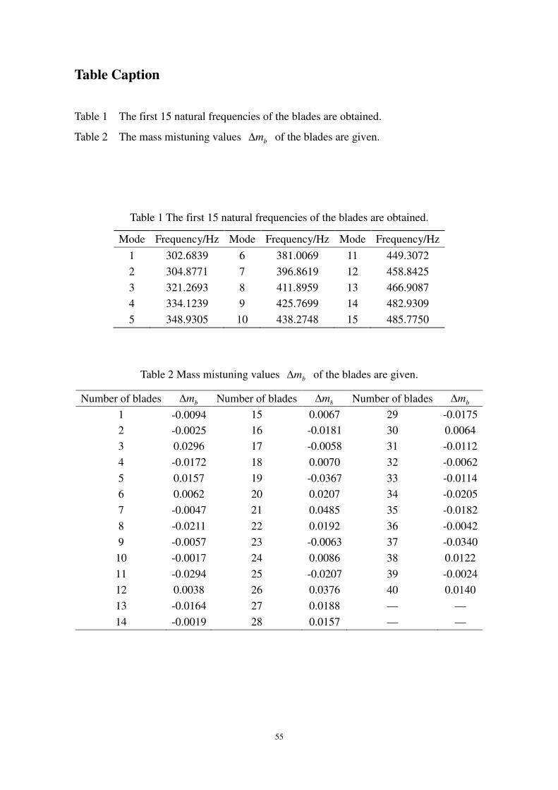
55
Table Caption
Table 1 The first 15 natural frequencies of the blades are obtained.
Table 2 The mass mistuning values bm of the blades are given.
Table 1 The first 15 natural frequencies of the blades are obtained.
Mode Frequency/Hz Mode Frequency/Hz Mode Frequency/Hz
1 302.6839 6 381.0069 11 449.3072
2 304.8771 7 396.8619 12 458.8425
3 321.2693 8 411.8959 13 466.9087
4 334.1239 9 425.7699 14 482.9309
5 348.9305 10 438.2748 15 485.7750
Table 2 Mass mistuning values bm of the blades are given.
Number of blades bm Number of blades bm Number of blades bm1 -0.0094 15 0.0067 29 -0.0175
2 -0.0025 16 -0.0181 30 0.0064
3 0.0296 17 -0.0058 31 -0.0112
4 -0.0172 18 0.0070 32 -0.0062
5 0.0157 19 -0.0367 33 -0.0114
6 0.0062 20 0.0207 34 -0.0205
7 -0.0047 21 0.0485 35 -0.0182
8 -0.0211 22 0.0192 36 -0.0042
9 -0.0057 23 -0.0063 37 -0.0340
10 -0.0017 24 0.0086 38 0.0122
11 -0.0294 25 -0.0207 39 -0.0024
12 0.0038 26 0.0376 40 0.0140
13 -0.0164 27 0.0188 — —
14 -0.0019 28 0.0157 — —