Embed Size (px)
Citation preview

March 2013 Ballot 2
© American Petroleum Institute Sept. 2011
Ballot 1 Comment Resolution - Final for Ballot 2
Nondestructive Examination (NDE) Services for Equipment used in the Petroleum and Natural Gas Industry
API STANDARD 20D FIRST EDITION, XXX 201X
This draft is for committee balloting purposes only.
This document is not an API Standard; it is under consideration within an API technical committee but has not
received all approvals required to become an API Standard. It shall not be reproduced or circulated or quoted,
in whole or in part, outside of API committee activities except with the approval of the Chairman of the
committee having jurisdiction and staff of the API Standards Dept. Copyright API. All rights reserved

This document is not an API Standard; it is under consideration within an API technical committee but has not received all approvals required to become an API Standard. It shall not be reproduced or circulated or quoted, in whole or in part, outside of API committee activities except with the approval of the Chairman of the committee having jurisdiction and staff of the API Standards Dept. Copyright API. All rights reserved
© American Petroleum Institute i
Foreword
Nothing contained in any API publication is to be construed as granting any right, by implication or otherwise, for the manufacture, sale, or use of any method, apparatus, or product covered by letters patent. Neither should anything contained in the publication be construed as insuring anyone against liability for infringement of letters patent.
The term “shall”, as used in this standard, denotes a minimum requirement in order to conform to the specification.
The term “should”, as used in this standard, denotes a recommendation or that which is advised but not required in order to conform to the specification.
This document was produced under API standardization procedures that ensure appropriate notification and participation in the developmental process and is designated as an API standard. Questions concerning the interpretation of the content of this publication or comments and questions concerning the procedures under which this publication was developed should be directed in writing to the Director of Standards, American Petroleum Institute, 1220 L Street, N.W., Washington, D.C. 20005. Requests for permission to reproduce or translate all or any part of the material published herein should also be addressed to the director.
Generally, API standards are reviewed and revised, reaffirmed, or withdrawn at least every five years. A one-time extension of up to two years may be added to this review cycle. Status of the publication can be ascertained from the API Standards Department, telephone (202) 682-8000. A catalog of API publications and materials is published annually and updated quarterly by API, 1220 L Street, N.W., Washington, D.C. 20005.
Suggested revisions are invited and should be submitted to the Standards Department, API, 1220 L Street, NW, Washington, DC 20005, [email protected].

This document is not an API Standard; it is under consideration within an API technical committee but has not received all approvals required to become an API Standard. It shall not be reproduced or circulated or quoted, in whole or in part, outside of API committee activities except with the approval of the Chairman of the committee having jurisdiction and staff of the API Standards Dept. Copyright API. All rights reserved
© American Petroleum Institute ii
Special Notes
API publications necessarily address problems of a general nature. With respect to particular circumstances, local, state, and federal laws and regulations should be reviewed.
Neither API nor any of API’s employees, subcontractors, consultants, committees, or other assignees make any warranty or representation, either express or implied, with respect to the accuracy, completeness, or usefulness of the information contained herein, or assume any liability or responsibility for any use, or the results of such use, of any information or process disclosed in this publication. Neither API nor any of API’s employees, subcontractors, consultants, or other assignees represent that use of this publication would not infringe upon privately owned rights.
API publications may be used by anyone desiring to do so. Every effort has been made by the Institute to assure the accuracy and reliability of the data contained in them; however, the Institute makes no representation, warranty, or guarantee in connection with this publication and hereby expressly disclaims any liability or responsibility for loss or damage resulting from its use or for the violation of any authorities having jurisdiction with which this publication may conflict.
API publications are published to facilitate the broad availability of proven, sound engineering and operating practices. These publications are not intended to obviate the need for applying sound engineering judgment regarding when and where these publications should be utilized. The formulation and publication of API publications is not intended in any way to inhibit anyone from using any other practices.

This document is not an API Standard; it is under consideration within an API technical committee but has not received all approvals required to become an API Standard. It shall not be reproduced or circulated or quoted, in whole or in part, outside of API committee activities except with the approval of the Chairman of the committee having jurisdiction and staff of the API Standards Dept. Copyright API. All rights reserved
© American Petroleum Institute iii
Table of Contents
Ballot 1 Comment Resolution - Final for Ballot 2............................................................................................ 1
Foreword .............................................................................................................................................................. i
Special Notes ...................................................................................................................................................... ii
Table of Contents .............................................................................................................................................. iii
1 Scope ...................................................................................................................................................... 1 1.1 Purpose .................................................................................................................................................. 1 1.2 Applicability ........................................................................................................................................... 1
2 Normative References .......................................................................................................................... 1
3 Terms and Definitions ........................................................................................................................... 2
4 Responsibilities and Duties ................................................................................................................. 4
5 Personnel Qualification Requirements ............................................................................................... 4
6 Design..................................................................................................................................................... 4
7 NDE Equipment and Calibration .......................................................................................................... 5 7.1 Inventory ................................................................................................................................................ 5 7.2 Calibration .............................................................................................................................................. 5
8 Quality Control Records Requirements .............................................................................................. 5 8.1 General ................................................................................................................................................... 5 8.2 Records Retention ................................................................................................................................ 6
9 NDE Processes, Equipment and Qualification Requirements.......................................................... 6 9.1 General ................................................................................................................................................... 6 9.2 Magnetic Particle Examination (MT) .................................................................................................... 6 9.2.1 General ................................................................................................................................................... 6 9.2.2 Calibration and Verification Requirements ........................................................................................ 6 9.2.3 Procedures ............................................................................................................................................. 7 9.2.4 Procedure Qualification ........................................................................................................................ 7 9.2.5 Procedure Requalification .................................................................................................................... 8 9.2.6 Records of Qualification ....................................................................................................................... 9 9.3 Liquid Penetrant Examination (PT) ................................................................................................... 10 9.3.1 Calibration and Verification Requirements ...................................................................................... 10 9.3.2 Procedures ........................................................................................................................................... 10 9.3.3 Procedure Qualification ...................................................................................................................... 10 9.3.4 Procedure Requalification .................................................................................................................. 11 9.3.5 Equipment and Facilities .................................................................................................................... 11 9.3.6 Process Validation .............................................................................................................................. 12 9.3.7 Records of Examination ..................................................................................................................... 12 9.4 Ultrasonic Examination (UT) .............................................................................................................. 14 9.4.1 General ................................................................................................................................................. 14 9.4.2 Procedures ........................................................................................................................................... 14 9.4.3 Procedure Qualification ...................................................................................................................... 14 9.4.4 Procedure Requalification .................................................................................................................. 14 9.4.5 Calibration and Verification Requirements ...................................................................................... 14 Calibration and Verification Requirements for Ultrasonic Examination Equipment ................................. 14 9.4.6 Techniques .......................................................................................................................................... 15
This document is not an API Standard; it is under consideration within an API technical committee but has not received all approvals required to become an API Standard. It shall not be reproduced or circulated or quoted, in whole or in part, outside of API committee activities except with the approval of the Chairman of the committee having jurisdiction and staff of the API Standards Dept. Copyright API. All rights reserved
© American Petroleum Institute iv
9.4.7 Equipment ............................................................................................................................................ 15 9.4.8 Calibration (Setup for Examination) .................................................................................................. 15 9.4.9 Records ................................................................................................................................................ 17 9.5 Radiographic Examination (RT) ......................................................................................................... 19 9.5.1 General ................................................................................................................................................. 19 9.5.2 Calibration and Verification Requirements ...................................................................................... 19 9.5.3 Facility Requirements ......................................................................................................................... 19 9.5.4 Process Validation .............................................................................................................................. 20 9.5.5 Equipment and Materials .................................................................................................................... 20 9.5.6 Process Control Checks ..................................................................................................................... 21 9.5.7 Quality of Radiographs ....................................................................................................................... 22 9.5.8 System of Identification ...................................................................................................................... 22 9.5.9 Records ................................................................................................................................................ 22

This document is not an API Standard; it is under consideration within an API technical committee but has not received all approvals required to become an API Standard. It shall not be reproduced or circulated or quoted, in whole or in part, outside of API committee activities except with the approval of the Chairman of the committee having jurisdiction and staff of the API Standards Dept. Copyright API. All rights reserved
© American Petroleum Institute 1
1 Scope
1.1 Purpose
This standard specifies requirements for the design, development and qualification of nondestructive examination methods used in the manufacturer of equipment for the petroleum and natural gas industries.
1.2 Applicability
This is applicable to suppliers providing nondestructive examination (NDE) services for equipment used in the oil and natural gas industries. The requirements of this standard apply to magnetic particle, liquid penetrant, radiography and ultrasonic methods of nondestructive examination.
2 Normative References
The following documents contain provisions which, through reference in this text, constitute provisions of this standard. For dated references, only the edition cited applies.
API Spec Q1, Specification for Quality Programs for the Petroleum, Petrochemical, and Natural Gas Industry
ASME Boiler and Pressure Vessel Code (BPVC), Section V, Nondestructive Examination
ASNT CP-189, Standard for Qualification and Certification of Nondestructive Testing Personnel
ASNT SNT-TC-1A, Personnel Qualification and Certification in Nondestructive Testing
ASTM B209, Standard Specification for Aluminum and Aluminum-Alloy Sheet and Plate
ASTM E428, Standard Practice for Fabrication and Control of Steel Reference Blocks Used in Ultrasonic Examination
ASTM E1114, Standard Test Method for Determining the Size of Iridium-192 Industrial Radiographic Sources
ASTM E1165, Standard Test Method for Measurement of Focal Spots of Industrial X-Ray Tubes by Pinhole Imaging
ASTM E1316, Standard Terminology for Nondestructive Examinations
ASTM E1417, Standard Practice for Liquid Penetrant Testing
EN 473, Non-destructive testing — Qualification and certification of NDT Personnel General Principles
ISO 9712, Non-destructive testing — Qualification and certification of personnel

This document is not an API Standard; it is under consideration within an API technical committee but has not received all approvals required to become an API Standard. It shall not be reproduced or circulated or quoted, in whole or in part, outside of API committee activities except with the approval of the Chairman of the committee having jurisdiction and staff of the API Standards Dept. Copyright API. All rights reserved
© American Petroleum Institute 2
3 Terms and Definitions
For purposes of this standard, the following terms, definitions, and acronyms apply.
Definitions relating to nondestructive examination, which appear in ASTM E1316, shall apply to the terms used in this standard.
3.1 acceptance criteria Defined limits placed on characteristics of materials, processes, products, or services.
3.2 calibration Comparison and adjustments to a standard of known accuracy.
3.3 check A process performed to maintain confidence in the calibration status of reference, primary, transfer or working standards and reference materials, carried out according to defined procedures and schedules.
3.4 visible method magnetic particle examination Magnetic particle inspection in which the particles are applied in a dry powder form where particles are visible in ambient light.
3.5 fluorescent method magnetic particle inspection The inspection process employing magnetic materials which have been coated with a material that fluoresces when activated by light of suitable wavelength.
3.6 immersion method ultrasonic examination The examination method in which the search unit and the test part are submerged in a fluid, usually water, which acts as the coupling medium.
3.7 linear indication An indication whose length is equal to or greater than three times its width.
3.8 liquid penetrant examination PT A NDE method for detecting surface breaking flaws by bleedout of a colored or fluorescent dye from the flaw.
3.9 magnetic particle examination MT A NDE method for detecting discontinuities on or near the surface in suitably magnetized materials, which employs finely divided magnetic particles that tend to congregate in regions of the magnetic non-uniformity, i.e., along cracks, over inclusions, voids, etc.

This document is not an API Standard; it is under consideration within an API technical committee but has not received all approvals required to become an API Standard. It shall not be reproduced or circulated or quoted, in whole or in part, outside of API committee activities except with the approval of the Chairman of the committee having jurisdiction and staff of the API Standards Dept. Copyright API. All rights reserved
© American Petroleum Institute 3
3.10 nondestructive examination NDE A method used to check the soundness of a material or a part without impairing or destroying the serviceability of the part.
3.11 procedure qualification The process whereby a written nondestructive examination procedure is qualified in accordance with the requirements of this standard.
3.12 radiography RT A nondestructive examination method wherein a source of X-rays or gamma rays, is utilized to indicate the subsurface condition of opaque materials.
3.13 radiographic quality level An expression of the quality of a radiograph in terms of an image quality indicator (penetrameter).
3.14 radiographic recording media When used in this standard, recording media may be radiographic film or digital technology
3.15 shear wave ultrasonic examination A type of wave in which the particle motion is perpendicular to the direction of propagation.
3.16 straight beam ultrasonic examination A vibrating pulse wave train traveling normal to the scan surface.
3.17 traceability The ability to verify the history, location, or application of an item by means of documented recorded identification.
3.18 ultrasonic examination UT A NDE method of testing materials by transmitting high frequency sound waves through them.
3.19 verification The adjustment of an NDE instrument using an appropriate reference standard, to obtain or establish a known and reproducible response. This is usually done prior to an examination, but can be carried out anytime there is concern about the examination or instrument response.
3.20 wet method magnetic particle examination The magnetic particle inspection method employing ferromagnetic particles suspended in a liquid bath.

This document is not an API Standard; it is under consideration within an API technical committee but has not received all approvals required to become an API Standard. It shall not be reproduced or circulated or quoted, in whole or in part, outside of API committee activities except with the approval of the Chairman of the committee having jurisdiction and staff of the API Standards Dept. Copyright API. All rights reserved
© American Petroleum Institute 4
4 Responsibilities and Duties
It is the responsibility of the NDE service supplier to ensure that it
— performs all examinations in accordance with specified standards or quality control criteria, or both,
— performs only examinations for which it is adequately equipped and staffed,
— performs only examinations for which its employees are adequately qualified,
— ensures equipment is calibrated and personnel are certified in accordance with applicable specifications,
— ensures all equipment is properly maintained,
— informs the purchaser of any discrepancy or limitation imposed on the testing accuracy by such factors as surface finish, form, shape, or procedure,
— calls to the attention of the purchaser at once any irregularity or deficiency noted in the documents, and
— submits promptly to the purchaser formal reports of all examinations that indicates compliance or noncompliance of the material. The NDE service supplier should be prepared to substantiate examination results when required,
— develops and qualifies procedures.
5 Personnel Qualification Requirements
Personnel performing NDE shall be qualified in accordance with the manufacturer's documented training program that is based on the requirements specified in ISO 9712, EN 473 or SNT-TC-1A. When SNT-TC-1A is used as the basis for qualification and certification, the content of the document must be considered as absolute requirements and not be considered a recommended practice as the title implies.
6 Design
The NDE service supplier shall have a system of written procedures for each NDE service performed. NDE procedures shall comply with the requirements of this standard and those of all applicable nationally or internationally recognized standards. The procedures shall include a description of the methods used for NDE and the methods used for data recording, data processing, data reporting, and for certification of the results.
The development of a NDE procedure shall comply with the design controls of API Spec Q1 or API Spec Q2, as appropriate. Individual(s) other than the person or persons who developed the procedure shall approve the final procedure. At least one individual approving the procedure shall be qualified and certified at Level III in accordance with the requirements of Section 5. Design and development changes including changes to procedures, shall require the same controls as the original design and development, and design documentation.

This document is not an API Standard; it is under consideration within an API technical committee but has not received all approvals required to become an API Standard. It shall not be reproduced or circulated or quoted, in whole or in part, outside of API committee activities except with the approval of the Chairman of the committee having jurisdiction and staff of the API Standards Dept. Copyright API. All rights reserved
© American Petroleum Institute 5
7 NDE Equipment and Calibration
7.1 Inventory
The NDE service supplier shall have an inventory listing of all available equipment with the following information noted:
— Name of the manufacturer;
— Equipment model and serial number;
— Characteristics subject to calibration;
— Range of operation and range of calibration;
— Reference to recognized internationally recognized standards used for calibration;
— Frequency of calibration;
— Allowable tolerances or maximum sensitivity;
7.2 Calibration
Equipment used to inspect, test or examine material or other equipment shall be identified, controlled, calibrated and adjusted at specified intervals in accordance with documented manufacturer instructions, and consistent with nationally or internationally recognized standards specified by the manufacturer, to maintain the accuracy required by this International standard. Records of calibration shall be maintained.
8 Quality Control Records Requirements
8.1 General
The quality control records required by this standard are necessary to substantiate that all services provided to meet this standard do conform to the specified requirements.
The NDE service supplier shall establish and maintain documented procedures to control the documents and data required by this standard.
Records to be maintained by manufacturer:
— NDE process records;
— NDE procedure;
— NDE procedure qualification record;
— NDE personnel qualification records.

This document is not an API Standard; it is under consideration within an API technical committee but has not received all approvals required to become an API Standard. It shall not be reproduced or circulated or quoted, in whole or in part, outside of API committee activities except with the approval of the Chairman of the committee having jurisdiction and staff of the API Standards Dept. Copyright API. All rights reserved
© American Petroleum Institute 6
8.2 Records Retention
Records required by this standard shall be maintained for five years after the date a procedure or qualification record is no longer used. Documents and data may be in any type of media (hard copy or electronic) and shall be
— signed and dated,
— maintained to demonstrate conformance to specified requirements,
— legible,
— retained and readily retrievable,
— stored in an environment to prevent damage, deterioration, or loss, and
— available and auditable by the user/purchaser.
9 NDE Processes, Equipment and Qualification Requirements
9.1 General
NDE processes and equipment shall be documented and qualified in accordance with the criteria defined for each method in this standard.
9.2 Magnetic Particle Examination (MT)
9.2.1 General
The magnetic particle method (MT) shall be performed using dry visible particle, wet visible particle or wet fluorescent particle method. One or more of the following five magnetization techniques shall be used:
— prod technique;
— longitudinal magnetization technique;
— circular magnetization technique;
— yoke technique;
— multi-directional magnetization technique.
9.2.2 Calibration and Verification Requirements
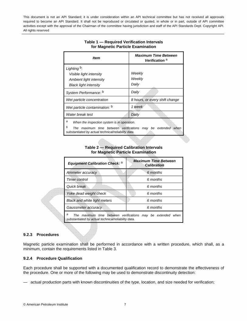
Magnetic particle examination equipment shall be calibrated and verified for performance and accuracy before first use and at intervals thereafter as indicated in Table 1 or Table 2, whenever malfunction is suspected or whenever electrical maintenance that might affect equipment accuracy is performed.
This document is not an API Standard; it is under consideration within an API technical committee but has not received all approvals required to become an API Standard. It shall not be reproduced or circulated or quoted, in whole or in part, outside of API committee activities except with the approval of the Chairman of the committee having jurisdiction and staff of the API Standards Dept. Copyright API. All rights reserved
© American Petroleum Institute 7
Table 1 — Required Verification Intervals for Magnetic Particle Examination
Item Maximum Time Between
Verification a
Lighting b:
Visible light intensity
Ambient light intensity
Black light intensity
Weekly
Weekly
Daily
System Performance: b Daily
Wet particle concentration 8 hours, or every shift change
Wet particle contamination: b 1 week
Water break test Daily
a When the inspection system is in operation.
b The maximum time between verifications may be extended when substantiated by actual technical/reliability data.
Table 2 — Required Calibration Intervals for Magnetic Particle Examination
Equipment Calibration Check: a Maximum Time Between
Calibration
Ammeter accuracy 6 months
Timer control 6 months
Quick break 6 months
Yoke dead weight check 6 months
Black and white light meters 6 months
Gaussmeter accuracy 6 months
a The maximum time between verifications may be extended when substantiated by actual technical/reliability data.
9.2.3 Procedures
Magnetic particle examination shall be performed in accordance with a written procedure, which shall, as a minimum, contain the requirements listed in Table 3.
9.2.4 Procedure Qualification
Each procedure shall be supported with a documented qualification record to demonstrate the effectiveness of the procedure. One or more of the following may be used to demonstrate discontinuity detection:
— actual production parts with known discontinuities of the type, location, and size needed for verification;
This document is not an API Standard; it is under consideration within an API technical committee but has not received all approvals required to become an API Standard. It shall not be reproduced or circulated or quoted, in whole or in part, outside of API committee activities except with the approval of the Chairman of the committee having jurisdiction and staff of the API Standards Dept. Copyright API. All rights reserved
© American Petroleum Institute 8
— representative reference parts containing discontinuities of the type, location, and size specified in the acceptance criteria and examined in accordance with a written procedure;
— Ketos ring.
NOTE Artificial discontinuities may be fabricated to meet a particular need or may be commercially available magnetic field indicators or shims.
Records of the qualification results shall be maintained and retained.
9.2.5 Procedure Requalification
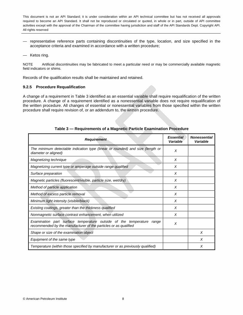
A change of a requirement in Table 3 identified as an essential variable shall require requalification of the written procedure. A change of a requirement identified as a nonessential variable does not require requalification of the written procedure. All changes of essential or nonessential variables from those specified within the written procedure shall require revision of, or an addendum to, the written procedure.
Table 3 — Requirements of a Magnetic Particle Examination Procedure
Requirement Essential Variable
Nonessential Variable
The minimum detectable indication type (linear or rounded) and size (length or diameter or aligned)
X
Magnetizing technique X
Magnetizing current type or amperage outside range qualified X
Surface preparation X
Magnetic particles (fluorescent/visible, particle size, wet/dry) X
Method of particle application X
Method of excess particle removal X
Minimum light intensity (visible/black) X
Existing coatings, greater than the thickness qualified X
Nonmagnetic surface contrast enhancement, when utilized X
Examination part surface temperature outside of the temperature range recommended by the manufacturer of the particles or as qualified
X
Shape or size of the examination object X
Equipment of the same type X
Temperature (within those specified by manufacturer or as previously qualified) X
This document is not an API Standard; it is under consideration within an API technical committee but has not received all approvals required to become an API Standard. It shall not be reproduced or circulated or quoted, in whole or in part, outside of API committee activities except with the approval of the Chairman of the committee having jurisdiction and staff of the API Standards Dept. Copyright API. All rights reserved
© American Petroleum Institute 9
9.2.6 Records of Qualification
9.2.6.1 Technique Sketch
A technique sketch shall be prepared for each different geometry qualified showing the part geometry, cable arrangement and connections, magnetizing current for each circuit, and the areas of examination where adequate field strengths are obtained
9.2.6.2 Recording of Indications
Rejectable indications shall be recorded. As a minimum, the type of indications (linear or rounded), location and extent (length or diameter or aligned) shall be recorded.
9.2.6.3 Examination Report
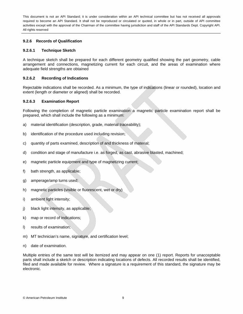
Following the completion of magnetic particle examination a magnetic particle examination report shall be prepared, which shall include the following as a minimum:
a) material identification (description, grade, material traceability);
b) identification of the procedure used including revision;
c) quantity of parts examined, description of and thickness of material;
d) condition and stage of manufacture i.e. as forged, as cast, abrasive blasted, machined;
e) magnetic particle equipment and type of magnetizing current;
f) bath strength, as applicable;
g) amperage/amp turns used;
h) magnetic particles (visible or fluorescent, wet or dry)
i) ambient light intensity;
j) black light intensity, as applicable;
k) map or record of indications;
l) results of examination;
m) MT technician’s name, signature, and certification level;
n) date of examination.
Multiple entries of the same test will be itemized and may appear on one (1) report. Reports for unacceptable parts shall include a sketch or description indicating locations of defects. All recorded results shall be identified, filed and made available for review. Where a signature is a requirement of this standard, the signature may be electronic.

This document is not an API Standard; it is under consideration within an API technical committee but has not received all approvals required to become an API Standard. It shall not be reproduced or circulated or quoted, in whole or in part, outside of API committee activities except with the approval of the Chairman of the committee having jurisdiction and staff of the API Standards Dept. Copyright API. All rights reserved
© American Petroleum Institute 10
9.3 Liquid Penetrant Examination (PT)
Liquid penetrant examination shall be performed using either a color contrast (visible) penetrant or a fluorescent type penetrant with one of the following three penetrant processes:
a) water washable;
b) post-emulsifying;
c) solvent removable.
The visible and fluorescent penetrants used in combination with these three penetrant methods result in six liquid penetrant processes. Each of the various process has been designed for specific uses such as critical service items, volume of parts, portability or localized areas of examination. The process selected will depend accordingly on the service requirements.
9.3.1 Calibration and Verification Requirements
Liquid penetrant examination equipment shall be calibrated and verified for performance and accuracy at intervals indicated below:
Table 4 — Required Calibration and Verification for Liquid Penetrant Examination
Calibration Check: a Maximum Time Between
Calibration
Penetrants and Emulsifiers Monthly for contamination
Dryers Monthly for thermostat accuracy
Light meters, fluorescent (black) and visible light
6 months
a The maximum time between verifications may be extended when substantiated by actual technical/reliability data.
9.3.2 Procedures
Liquid penetrant examination shall be performed in accordance with a written procedure, which shall as a minimum, contain the requirements listed in Table 5.
9.3.3 Procedure Qualification
9.3.3.1 General
Each procedure shall be supported with a documented qualification record to demonstrate the effectiveness of the procedure. One or more of the following may be used to demonstrate discontinuity detection:
— actual production parts with known discontinuities of the type, location, and size needed for verification;

This document is not an API Standard; it is under consideration within an API technical committee but has not received all approvals required to become an API Standard. It shall not be reproduced or circulated or quoted, in whole or in part, outside of API committee activities except with the approval of the Chairman of the committee having jurisdiction and staff of the API Standards Dept. Copyright API. All rights reserved
© American Petroleum Institute 11
— representative reference parts containing discontinuities of the type, location, and size specified in the acceptance criteria and examined in accordance with a written procedure,
— comparator blocks or other test panels (e.g., tam panels, crack panels, etc.).
9.3.4 Procedure Requalification
A change of a requirement in Table 5 identified as an essential variable shall require requalification of the written procedure. A change of a requirement identified as a nonessential variable does not require requalification of the written procedure. All changes of essential or nonessential variables from those specified within the written procedure shall require revision of, or an addendum to, the written procedure.
Table 5 — Requirements of a Liquid Penetrant Examination Procedure
Requirement Essential Variable
Nonessential Variable
The minimum detectable indication type (linear or rounded) and size (length or diameter or aligned)
X
Identification of and any change in type or family group of penetrant materials including developers, emulsifiers, etc.
X
Surface preparation (finishing and cleaning, including type of cleaning solvent) X
Method of applying penetrant X
Method of removing excess surface penetrant X
Hydrophilic or lipophilic emulsifier concentration and dwell time in dip tanks and agitation time for hydrophilic emulsifiers
X
Hydrophilic emulsifier concentration in spray applications X
Method of applying developer X
Minimum and maximum time periods between steps and drying aids X
Decrease in penetrant dwell time X
Increase in developer dwell time (interpretation time) X
Minimum light intensity X
Surface temperature outside 40°F to 125°F (5°C to 52°C) or as previously qualified X
Performance demonstration, when required X
Personnel qualification requirements . X
Materials, shapes, or sizes to be examined and the extent of examination X
Post-examination cleaning technique X
9.3.5 Equipment and Facilities
6.3.5.1 General
Equipment used in the penetrant examination process shall be constructed and arranged to permit a uniform and controlled operation. The equipment shall meet all applicable national and local safety requirements as well as the requirements specified herein.

This document is not an API Standard; it is under consideration within an API technical committee but has not received all approvals required to become an API Standard. It shall not be reproduced or circulated or quoted, in whole or in part, outside of API committee activities except with the approval of the Chairman of the committee having jurisdiction and staff of the API Standards Dept. Copyright API. All rights reserved
© American Petroleum Institute 12
9.3.5.2 Viewing Areas
Lighting shall comply with the requirements of the applicable standards referenced within the procedure being qualified.
9.3.6 Process Validation
The penetrant system’s overall performance shall be checked as specified in Table 6. The check shall be performed by processing a known defect standard (comparator block) conforming to 9.3.3.1 through the system using in-use penetrant, emulsifier (if used) and developer and appropriate processing parameters. The resulting indications will then be compared to the indications obtained using unused penetrant, emulsifier (if used) and developer. This comparison may be made with records of previously obtained indications or with a similar known defect standard processed with unused material. When the sensitivity or performance of the in-use materials falls below the performance of the unused materials, the in-use materials shall be checked in accordance with ASTM E1417, prior to conducting any further penetrant examinations. Unacceptable materials shall be discarded or otherwise corrected in accordance with the manufacturer’s instruction.
9.3.7 Records of Examination
9.3.7.1 Recording of Indications
Rejectable indications shall be recorded. As a minimum, the type of indications (linear or rounded), location and extent (length or diameter or aligned) shall be recorded.
9.3.7.2 Examination Report
Following the completion of liquid penetrant examination an examination report shall be prepared, which shall include the following, as a minimum:
— material identification (description, material traceability);
— identification of the procedure used including revision;
— quantity of parts examined, description of material;
— condition and stage of manufacture i.e. as forged, as cast, abrasive blasted, machined;
— type and method of liquid penetrant used;
— black light intensity, when applicable;
— results of examination;
— PT technician’s printed name, signature and certification level;
— date of examination.
Multiple entries of the same test shall be itemized and may appear on one (1) report. Separate reports are required for acceptable and rejectable results. Reports for unacceptable parts shall include a sketch showing locations of defects. All recorded results shall be identified, filed and made available for review. Where a signature is a requirement of this standard, the signature may be electronic.

This document is not an API Standard; it is under consideration within an API technical committee but has not received all approvals required to become an API Standard. It shall not be reproduced or circulated or quoted, in whole or in part, outside of API committee activities except with the approval of the Chairman of the committee having jurisdiction and staff of the API Standards Dept. Copyright API. All rights reserved
© American Petroleum Institute 13
Table 6
Required Performance Tests and Frequency for Liquid Penetrant Systems
Tests Frequency
Penetrant Contamination a Daily
Penetrant Brightness Quarterly
Water Content - Water-Based Penetrant (Method A) Weekly
Water Content – Non-Water-Based Penetrant (Method A) Monthly
Lipophilic Emulsifier Water Content b Monthly
Hydrophilic Emulsifier Concentration b Weekly
Dry Developer Condition b Daily
Aqueous Developer Contamination – Soluble and Suspendable Daily
Aqueous Developer Concentration – Soluble and Suspendable Weekly
Penetrant System Performance c Daily
Water-Washable Penetrant Removability As required per ASTM E1417
Emulsifier Removability As required per ASTM E1417
Comparative Penetrant Sensitivity As required per ASTM E1417
Black Light Intensity Daily
Black Light Integrity Weekly Weekly
Special UV lighting Daily
Visible Light Intensity Weekly
Light Meter Calibration b Semi-annually
Inspection Area Cleanliness a Daily
Inspection Area Ambient Light Intensity Quarterly
Water Wash Pressure Check a Start of each working shift
Water Pressure Gage Calibration b Semi-annually
Water Wash Temperature Check a Start of each working shift
Water Temperature Gage Calibration b Semi-annually
Drying Oven Calibration b Quarterly
a Need not be recorded.
b The maximum time between verifications or checks may be extended when substantiated by technical data.
c Not required for solvent-removable examinations.

This document is not an API Standard; it is under consideration within an API technical committee but has not received all approvals required to become an API Standard. It shall not be reproduced or circulated or quoted, in whole or in part, outside of API committee activities except with the approval of the Chairman of the committee having jurisdiction and staff of the API Standards Dept. Copyright API. All rights reserved
© American Petroleum Institute 14
9.4 Ultrasonic Examination (UT)
9.4.1 General
Ultrasonic Testing (UT) uses high frequency sound energy to conduct examinations and make measurements. Ultrasonic inspection can be used for flaw detection/evaluation, dimensional measurements, material characterization, and more.
9.4.2 Procedures
Ultrasonic examination shall be performed in accordance with a written procedure, which shall, as a minimum, contain the requirements listed in Table 7.
9.4.3 Procedure Qualification
Each procedure shall be supported with a documented qualification record to demonstrate the effectiveness of the procedure. One or more of the following may be used to demonstrate discontinuity detection:
— actual production parts with known discontinuities of the type, location, and size needed for verification;
— representative reference parts containing discontinuities of the type, location, and size specified in the acceptance criteria and examined in accordance with a written procedure;
— calibration block in accordance with 9.4.7.4.1.
9.4.4 Procedure Requalification
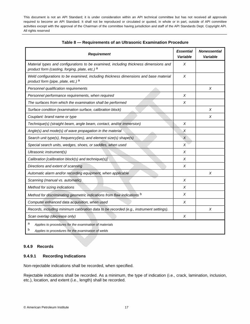
A change of a requirement in Table 6 identified as an essential variable shall require requalification of the written procedure. A change of a requirement identified as a nonessential variable does not require requalification of the written procedure. All changes of essential or nonessential variables from those specified within the written procedure shall require revision of, or an addendum to, the written procedure.
9.4.5 Calibration and Verification Requirements
9.4.5.1 Ultrasonic examination equipment shall be calibrated and verified for performance and accuracy at intervals indicated in Table 7.
Table 7 Calibration and Verification Requirements for Ultrasonic Examination Equipment
Instrument linearity checks
The requirements of 7.2 shall be met at intervals not to exceed three months for analog type instruments and one year for digital type instruments, or prior to first use thereafter.
Screen height linearity
Evaluate in accordance with ASME BPVC, Section V, Article 4.
Amplitude control linearity Evaluate in accordance with ASME BPVC, Section V, Article 4.

This document is not an API Standard; it is under consideration within an API technical committee but has not received all approvals required to become an API Standard. It shall not be reproduced or circulated or quoted, in whole or in part, outside of API committee activities except with the approval of the Chairman of the committee having jurisdiction and staff of the API Standards Dept. Copyright API. All rights reserved
© American Petroleum Institute 15
9.4.6 Techniques
Ultrasonic examination may be performed using the following contact and/or immersion techniques:
— straight beam;
— angle beam (shear wave).
9.4.7 Equipment
9.4.7.1 Instrument
A pulse-echo type of ultrasonic instrument shall be used. The instrument shall be capable of operation at frequencies over the range of at least 1 MHz to 5 MHz, and shall be equipped with a stepped gain control in units of 2.0 dB or less. The reject control shall be in the “off” position for all examinations. The instrument, when required because of the technique being used, shall have both send and receive jacks for operation of dual search units or a single search unit with send and receive transducers.
9.4.7.2 Search Units
The nominal frequency shall be from 1 MHz to 5 MHz unless variables such as production material grain structure require the use of other frequencies to assure adequate penetration or better resolution. Search units with contoured contact wedges may be used to aid ultrasonic coupling.
9.4.7.3 Couplant
The couplant, including additives, shall not be detrimental to the material being examined.
9.4.7.4 Calibration Blocks
9.4.7.4.1 General
Calibration blocks shall conform to a recognized industry, national or international standard relevant to the scope of work performed by the NDE service supplier such as ASTM E428 or ASME BPVC, Section V. Calibration blocks shall be serialized and certified to applicable standards.
9.4.7.4.2 Material Requirements
The material from which the block is fabricated shall be of the same product form, material specification or equivalent and shall be acoustically similar in velocity and attenuation to the material being examined. The finish on the scanning surface of the block shall be representative of the scanning surface finish on the material to be examined. Whenever practical, the application of a transfer correction, as addressed in the written procedure, is applied to the scanning surface when its surface is not representative of the reference standard surface.
9.4.8 Calibration (Setup for Examination)
9.4.8.1 General
Calibrations shall include the complete ultrasonic system and shall be performed prior to use of the system in the thickness range under examination in accordance with the NDE service supplier’s written specification.

This document is not an API Standard; it is under consideration within an API technical committee but has not received all approvals required to become an API Standard. It shall not be reproduced or circulated or quoted, in whole or in part, outside of API committee activities except with the approval of the Chairman of the committee having jurisdiction and staff of the API Standards Dept. Copyright API. All rights reserved
© American Petroleum Institute 16
9.4.8.2 Calibration Surface
Calibrations shall be performed from the surface (clad or unclad; convex or concave) corresponding to the surface of the material for which the examination will be performed.
9.4.8.3 Couplant
The same couplant to be used during the examination shall be used for calibration.
9.4.8.4 Contact Wedges
The same contact wedges to be used during the examination shall be used for calibration.
9.4.8.5 Instrument Controls
Any control, which affects instrument linearity (e.g., filters, reject, or clipping), shall be in the same position for calibration, calibration checks, instrument linearity checks, and examination.
9.4.8.6 Temperature
For contact examination, the temperature differential between the calibration block and examination surfaces shall be within 25°F (14°C). For immersion examination, the couplant temperature for calibration shall be within 25°F (14°C) of the couplant temperature for examination.
9.4.8.7 Calibration Confirmation
When any of the examination variables specified in Table 7 are changed, a calibration check shall be made to verify distance range points and sensitivity setting.
9.4.8.8 Calibration Checks
A calibration check in accordance with specified requirements shall be performed at the completion of each examination or series of similar examinations, and when examination personnel (except for automated equipment) are changed.
NOTE: Interim calibration checks between the required initial calibration and the final calibration check may be performed. The decision to perform interim calibration checks should be based on ultrasonic instrument stability (analog vs. digital), the risk of having to conduct reexaminations, and the benefit of not performing interim calibration checks.
This document is not an API Standard; it is under consideration within an API technical committee but has not received all approvals required to become an API Standard. It shall not be reproduced or circulated or quoted, in whole or in part, outside of API committee activities except with the approval of the Chairman of the committee having jurisdiction and staff of the API Standards Dept. Copyright API. All rights reserved
© American Petroleum Institute 17
Table 8 — Requirements of an Ultrasonic Examination Procedure
Requirement Essential
Variable
Nonessential
Variable
Material types and configurations to be examined, including thickness dimensions and product form (casting, forging, plate, etc.) a
X
Weld configurations to be examined, including thickness dimensions and base material product form (pipe, plate, etc.) a
X
Personnel qualification requirements X
Personnel performance requirements, when required X
The surfaces from which the examination shall be performed X
Surface condition (examination surface, calibration block) X
Couplant: brand name or type X
Technique(s) (straight beam, angle beam, contact, and/or immersion) X
Angle(s) and mode(s) of wave propagation in the material X
Search unit type(s), frequency(ies), and element size(s) shape(s) X
Special search units, wedges, shoes, or saddles, when used X
Ultrasonic instrument(s) X
Calibration [calibration block(s) and technique(s)] X
Directions and extent of scanning X
Automatic alarm and/or recording equipment, when applicable X
Scanning (manual vs. automatic) X
Method for sizing indications X
Method for discriminating geometric indications from flaw indications b X
Computer enhanced data acquisition, when used X
Records, including minimum calibration data to be recorded (e.g., instrument settings). X
Scan overlap (decrease only) X
a Applies to procedures for the examination of materials
b Applies to procedures for the examination of welds
9.4.9 Records
9.4.9.1 Recording Indications
Non-rejectable indications shall be recorded, when specified.
Rejectable indications shall be recorded. As a minimum, the type of indication (i.e., crack, lamination, inclusion, etc.), location, and extent (i.e., length) shall be recorded.
This document is not an API Standard; it is under consideration within an API technical committee but has not received all approvals required to become an API Standard. It shall not be reproduced or circulated or quoted, in whole or in part, outside of API committee activities except with the approval of the Chairman of the committee having jurisdiction and staff of the API Standards Dept. Copyright API. All rights reserved
© American Petroleum Institute 18
9.4.9.2 Examination Records
For each ultrasonic examination, the following information shall be recorded:
d) procedure identification and revision;
e) ultrasonic instrument identification (including manufacturer’s serial number);
f) search unit(s) identification (including manufacturer’s serial number, frequency, and size);
g) beam angle(s) used;
h) couplant used, brand name or type;
i) search unit cable(s) used, type and length;
j) special equipment, when used (search units, wedges, shoes, automatic scanning equipment, recording equipment, etc.);
k) computerized program identification and revision, when used;
l) calibration block identification;
m) simulation block(s) and electronic simulator(s) identification, when used;
n) instrument reference level gain and, if used, damping and reject setting(s);
o) calibration data [including reference reflector(s), indication amplitude(s), and distance reading(s)];
p) data correlating simulation block(s) and electronic simulator(s), when used, with initial calibration;
q) identification of material or volume scanned;
r) surface(s) from which examination was conducted, including surface condition;
s) map or record of rejectable indications detected or areas cleared;
t) areas of restricted access or inaccessible areas;
u) examination personnel identity and qualification level;
v) date of examination.
NOTE Items (b) through (m) may be included in a separate calibration record provided the calibration record identification is included in the examination record.
9.4.9.3 Examination Report
A report of the examinations shall be made. The report shall include those records indicated in 9.4.8.1 and 9.4.8.2.
This document is not an API Standard; it is under consideration within an API technical committee but has not received all approvals required to become an API Standard. It shall not be reproduced or circulated or quoted, in whole or in part, outside of API committee activities except with the approval of the Chairman of the committee having jurisdiction and staff of the API Standards Dept. Copyright API. All rights reserved
© American Petroleum Institute 19
9.5 Radiographic Examination (RT)
9.5.1 General
Radiography involves the use of penetrating gamma or x-radiation to examine materials and welds for discontinuities. An x-ray generator or radioactive isotope is used as a source of radiation. Radiation is directed through a part and onto film or other imaging media. The resulting radiograph shows the dimensional features of the part with possible discontinuities indicated as density changes on the film.
9.5.2 Calibration and Verification Requirements
9.5.2.1 Radiographic examination equipment shall be calibrated and verified for performance and accuracy at intervals indicated below:
Table 9
Calibration and Verification Requirements for Radiographic Examination Equipment
Verification of source size
The equipment manufacturer’s or supplier’s publications, such as technical manuals, decay curves, or written statements documenting the actual or maximum source size or focal spot, shall be acceptable as source size verification.
Determination of source size
a) X-Ray Machines. For X-ray machines operating at 500 kV and less, the focal spot size may be determined by the Pinhole Method 1 or in accordance with ASTM E1165.
b) Gamma Sources. Gamma source size shall be determined in accordance to ASTM-E1114 or other appropriate written specifications.
9.5.3 Facility Requirements
Radiographic exposure areas shall be clean and equipped so that acceptable radiographs may be produced in accordance with the requirements of this standard.
Darkroom facilities, including equipment and materials, shall be capable of producing uniform radiographs free of blemishes or artifacts, which might interfere with interpretation in the area of interest.
The film viewing room or enclosure shall be an area with subdued lighting to preclude objectionable reflective Procedure
The NDE service supplier shall develop a workable examination technique recorded as a written procedure that is capable of consistently producing the desired results and radiographic quality level. All written procedures shall be approved by an individual qualified and certified as a Level III for radiography in accordance with Section 5.
The written procedure shall contain, as a minimum, the following information, either directly or by reference to the applicable requirements.
(a) material type (example - casting, plate, pipe, weld) and thickness range;

This document is not an API Standard; it is under consideration within an API technical committee but has not received all approvals required to become an API Standard. It shall not be reproduced or circulated or quoted, in whole or in part, outside of API committee activities except with the approval of the Chairman of the committee having jurisdiction and staff of the API Standards Dept. Copyright API. All rights reserved
© American Petroleum Institute 20
(b) isotope or maximum X-ray voltage to be used;
(c) source-to-object distance;
(d) distance from source side of object to film;
(e) source diagonal, size, and serial number;
(f) recording media (details of digital technique or film brand and designation);
(g) screens used;
(h) image quality indicators;
(i) density;
(j) quality level and sensitivity.
Note: When a standard hole-type penetrameter is used, quality level is stated as a-bT, where a is the penetrameter thickness, expressed as a percentage of the maximum thickness of the specimen, and b is the diameter of the smallest discernible hole, expressed as a multiple of penetrameter thickness, T.
Example: the 2-2T quality level means that the penetrameter thickness equals 2 percent of maximum specimen thickness, and the smallest discernible penetrameter hole has a diameter equal to twice the penetrameter thickness.
9.5.4 Process Validation
Demonstration of the density and image quality indicator (IQI) image requirements of the written procedure on production or technique radiographs shall be considered satisfactory evidence of process validation.
9.5.5 Equipment and Materials
9.5.5.1 General
The radiation source shall be capable of producing sufficient energy and intensity to examine materials in accordance with required specifications.
9.5.5.2 X-Ray
X-ray equipment should contain voltage and amperage controls (when applicable) and meters, a timer to time the length of the exposure, or other approved controls, and provisions for positioning the tube head and the part being X-rayed (when applicable). The suitability of these exposure parameters shall be demonstrated by attainment of the required radiographic quality level.
9.5.5.3 Gamma Ray
Gamma rays are produced by radioactive materials, such as cobalt-60, iridium-192 and selenium-75. Different isotopes emit gamma rays in a specific energy range. Isotope sources that are used shall be capable of demonstrating the required radiographic quality level.

This document is not an API Standard; it is under consideration within an API technical committee but has not received all approvals required to become an API Standard. It shall not be reproduced or circulated or quoted, in whole or in part, outside of API committee activities except with the approval of the Chairman of the committee having jurisdiction and staff of the API Standards Dept. Copyright API. All rights reserved
© American Petroleum Institute 21
9.5.5.4 Intensifying Screens
Intensifying screens may be used when performing radiographic examination in accordance with this standard. Fluorescent intensifying screens shall not be used.
9.5.5.5 Image Quality Indicator (IQI)
Image quality indicators (IQI)s shall be either the hole type or the wire type manufactured in accordance with recognized industry standards.
9.5.5.6 Densitometers
Densitometers, when used, shall be capable of measuring the light transmitted through a radiograph with a film density up to 4.0 with a density unit resolution of 0.02. When film densities greater than 4.0 are permitted, a densitometer capable of measuring densities up to the maximum density permitted is required.
9.5.6 Process Control Checks
Devices used in the performance of radiographic examination shall inspected and examined/calibrated in accordance with Table 10.
Table 10— Process Control Checks/Calibration for Radiographic Examinations
Check Frequency
Discontinuity Image Measuring Device When procured
Image Quality Indicators Certified when procured
Check (Condition) prior to use
Automatic Processing
Processor Performance Daily
Base Fog Daily
Developer Temperature Prior to use
Replenishment Rate
Transport Speed
Daily
Daily
Prior to use
When solutions are changed
During maintenance or repair
Manual Processing:
Processing Performance Daily
Base plus Fog Monthly
Developer Temperature prior to use
Daily
Monthly
Prior to use
Densitometer
Verification Check
Calibration Check
Each shift
90 days
Light Meters Annual
Viewer Light Intensity When procured
Thermometer Calibration 6 months
Ambient Visible Light 6 months
Step wedge Calibration Annual

This document is not an API Standard; it is under consideration within an API technical committee but has not received all approvals required to become an API Standard. It shall not be reproduced or circulated or quoted, in whole or in part, outside of API committee activities except with the approval of the Chairman of the committee having jurisdiction and staff of the API Standards Dept. Copyright API. All rights reserved
© American Petroleum Institute 22
9.5.7 Quality of Radiographs
All radiographs shall be free from mechanical, chemical or other blemishes to the extent that they do not mask and are not confused with the image of any discontinuity in the area of interest of the object being radiographed.
9.5.8 System of Identification
A system shall be used to produce permanent identification on the radiograph traceable to the contract, component, weld or weld seam, or part numbers, as appropriate. In addition, the NDE service supplier’s symbol or name and the date of the radiograph shall be plainly and permanently included on the radiograph. This identification system does not necessarily require that the information appear as radiographic images. In any case, this information shall not obscure the area of interest.
9.5.9 Records
9.5.9.1 Radiographic Technique Documentation
The NDE service supplier shall prepare and document the radiographic technique details. As a minimum, the following information shall be provided:
a) identification as required by 9.5.8;
a. marker placement, if essential for interpretation;
b. number of radiographs (exposures);
c. x-ray voltage or isotope type used;
d. source diagonal, size and serial number or effective focal length size;
e. base material type and thickness, weld thickness, weld reinforcement thickness, as applicable;
f. source-to-object distance;
g. distance from source side of object to film;
h. film manufacturer and Manufacturer’s type/designation;
i. number of film in each film holder/cassette;
j. single or double-wall exposure;
k. single or double-wall viewing.
9.5.9.2 Radiograph Review Form
The NDE service supplier shall prepare a radiograph review form. As a minimum, the following information shall be provided:
a) a listing of each radiograph location;
This document is not an API Standard; it is under consideration within an API technical committee but has not received all approvals required to become an API Standard. It shall not be reproduced or circulated or quoted, in whole or in part, outside of API committee activities except with the approval of the Chairman of the committee having jurisdiction and staff of the API Standards Dept. Copyright API. All rights reserved
© American Petroleum Institute 23
b) the information required in 9.5.9.1 by inclusion or by reference;
c) evaluation and disposition of the material(s) or weld(s) examined;
d) identification (name) of the NDE service supplier’s representative who performed the final acceptance of the radiographs (e) date of Manufacturer’s evaluation.