Embed Size (px)
Citation preview
ScienceDirect
Available online at www.sciencedirect.com
Available online at www.sciencedirect.com
ScienceDirect
Structural Integrity Procedia 00 (2016) 000–000 www.elsevier.com/locate/procedia
2452-3216 © 2016 The Authors. Published by Elsevier B.V. Peer-review under responsibility of the Scientific Committee of PCF 2016.
XV Portuguese Conference on Fracture, PCF 2016, 10-12 February 2016, Paço de Arcos, Portugal
Thermo-mechanical modeling of a high pressure turbine blade of an airplane gas turbine engine
P. Brandãoa, V. Infanteb, A.M. Deusc* aDepartment of Mechanical Engineering, Instituto Superior Técnico, Universidade de Lisboa, Av. Rovisco Pais, 1, 1049-001 Lisboa,
Portugal bIDMEC, Department of Mechanical Engineering, Instituto Superior Técnico, Universidade de Lisboa, Av. Rovisco Pais, 1, 1049-001 Lisboa,
Portugal cCeFEMA, Department of Mechanical Engineering, Instituto Superior Técnico, Universidade de Lisboa, Av. Rovisco Pais, 1, 1049-001 Lisboa,
Portugal
Abstract
During their operation, modern aircraft engine components are subjected to increasingly demanding operating conditions, especially the high pressure turbine (HPT) blades. Such conditions cause these parts to undergo different types of time-dependent degradation, one of which is creep. A model using the finite element method (FEM) was developed, in order to be able to predict the creep behaviour of HPT blades. Flight data records (FDR) for a specific aircraft, provided by a commercial aviation company, were used to obtain thermal and mechanical data for three different flight cycles. In order to create the 3D model needed for the FEM analysis, a HPT blade scrap was scanned, and its chemical composition and material properties were obtained. The data that was gathered was fed into the FEM model and different simulations were run, first with a simplified 3D rectangular block shape, in order to better establish the model, and then with the real 3D mesh obtained from the blade scrap. The overall expected behaviour in terms of displacement was observed, in particular at the trailing edge of the blade. Therefore such a model can be useful in the goal of predicting turbine blade life, given a set of FDR data. © 2016 The Authors. Published by Elsevier B.V. Peer-review under responsibility of the Scientific Committee of PCF 2016.
Keywords: High Pressure Turbine Blade; Creep; Finite Element Method; 3D Model; Simulation.
* Corresponding author. Tel.: +351 218419991.
E-mail address: [email protected]
Procedia Structural Integrity 2 (2016) 2132–2139
Copyright © 2016 The Authors. Published by Elsevier B.V. This is an open access article under the CC BY-NC-ND license (http://creativecommons.org/licenses/by-nc-nd/4.0/).Peer review under responsibility of the Scientific Committee of ECF21.10.1016/j.prostr.2016.06.267
10.1016/j.prostr.2016.06.267
Available online at www.sciencedirect.com
ScienceDirect
Structural Integrity Procedia 00 (2016) 000–000 www.elsevier.com/locate/procedia
2452-3216 © 2016 The Authors. Published by Elsevier B.V. Peer-review under responsibility of the Scientific Committee of ECF21.
21st European Conference on Fracture, ECF21, 20-24 June 2016, Catania, Italy
Nondestructive Evaluation of Fatigue Cracks in Steel Bridges Based on Thermoelastic Stress Measurement
Takahide Sakagami a*, Yui Izumi b, Daiki Shiozawa a, Taisei Fujimoto a, Yoshiaki Mizokami c, Taku Hanai c
a Dept. of Mechanical Engineering, Kobe University, b The University of Shiga Prefecture,
c Honshu-Shikoku Bridge Expressway Company Limited
Abstract
Long-standing steel bridges suffer fatigue cracks, which necessitate immediate inspection, structural integrity evaluation or repair in the life cycle of steel bridges. The authors proposed NDT and NDE techniques employing infrared thermography at certain stage in the life cycle of steel bridges. This paper presents remote measurement of stress field around fatigue cracks in steel bridges for their structural integrity assessments. Further this paper shows experimental results confirming the severity reduction of stress distribution around fatigue cracks after the repair or reinforcement of steel bridges. © 2016 The Authors. Published by Elsevier B.V. Peer-review under responsibility of the Scientific Committee of ECF21.
Keywords: Nondestructive Evaluation, Thermoelasticity, Infrared Thermography, Fatigue Cracks, Steel Bridges
1. Introduction
Problems of fatigue cracks propagating from welded joints in steel bridges is one of the most serious problems associated with deterioration in relation to ageing infrastructures. Inspection of deterioration or damage is necessary to ensure safety and estimate the remaining strength of the steel bridges. In this respect, nondestructive testing (NDT) and nondestructive evaluation (NDE) techniques play an important role. Conventional NDT techniques for
* Corresponding author. Tel.: +81-78-803-6343; fax: +81-78-803-6343.
E-mail address: [email protected]
2 Takahide Sakagami / Structural Integrity Procedia 00 (2016) 000–000
steel bridges include visual testing, eddy current testing, magnetic particle testing and ultrasonic testing. However, there are a reported number of over 0.7 million bridges that require inspection, and the conventional NDT techniques are time-intensive and labor-intensive techniques that require special equipment for inspection, such as scaffolding. It is not realistically possible to employ conventional NDT techniques. Therefore, development of a high-performance NDT method is essential for the effective maintenance of ageing steel bridges. In addition, a structural integrity evaluation is considered essential for the fitness for service evaluation of ageing steel bridges. For accurate structural integrity evaluation it is required to obtain actual applied stress distribution around a fatigue crack and its history due to the moving wheel load by vehicles on the bridge. Conventional stress and strain measurement techniques are insufficient for these requirements. Therefore, a stress measurement technique that enables remote and full-field measurements of the stress distribution around fatigue cracks should be developed for the structural integrity evaluation of steel bridges.
Fig. 1. Development of life cycle NDT and NDE techniques using infrared thermography for fatigue cracks in steel bridges.
The present authors developed remote NDT and NDE techniques using infrared thermography. Figure 1 shows the development of life cycle NDT and NDE for steel bridges using infrared thermography proposed by Sakagami (2015). The first signs of deterioration in ageing steel bridges are the initiation of fatigue cracks. It would be beneficial to predict the occurrence and location of fatigue crack initiation. Shiozawa et al. (2014) investigated the feasibility of dissipated energy measurement for predicting fatigue crack initiation and fatigue limit evaluation related with the generation and motion of slip bands. After fatigue crack initiation, detection of fatigue cracks is required for maintenance of steel bridges. Sakagami et al. (2014) developed a relatively simple but useful NDT technique for fatigue crack detection based on the temperature gap that appears on the surface of structural members because of the thermal insulation effect of the crack. Fatigue cracks can be detected based on the stress distribution around crack tips measured by thermoelastic stress measurement using infrared thermography. Sakagami et al. (2005) developed a self-reference lock-in thermography technique for S/N improvement that does not require any external reference signals and can be employed even under irregular waveform loading. Once a fatigue crack initiates, it is necessary to evaluate its size and propagation rate, and fracture mechanics analysis then needs to be conducted accurately to evaluate the remaining strength. Sakagami et al. (2010) effectively applied thermoelastic stress measurement for the full-field stress distribution measurement around crack tips, followed by a fracture mechanics evaluation using the stress intensity factor. Furthermore, after ample crack propagation, steel bridges then require repair or reinforcement to prolong their life. After the repair or reinforcement of a steel bridge, it is essential to confirm the reduction in the severity of the stress distribution around the defect portion.
In this paper, the authors focus on the repair techniques for the members of steel bridge with fatigue cracks and the confirmation of reduction in the severity of the stress distribution around the repaired portion using thermoelastic
Copyright © 2016 The Authors. Published by Elsevier B.V. This is an open access article under the CC BY-NC-ND license (http://creativecommons.org/licenses/by-nc-nd/4.0/).Peer-review under responsibility of the Scientific Committee of ECF21.

Takahide Sakagami et al. / Procedia Structural Integrity 2 (2016) 2132–2139 2133
Available online at www.sciencedirect.com
ScienceDirect
Structural Integrity Procedia 00 (2016) 000–000 www.elsevier.com/locate/procedia
2452-3216 © 2016 The Authors. Published by Elsevier B.V. Peer-review under responsibility of the Scientific Committee of ECF21.
21st European Conference on Fracture, ECF21, 20-24 June 2016, Catania, Italy
Nondestructive Evaluation of Fatigue Cracks in Steel Bridges Based on Thermoelastic Stress Measurement
Takahide Sakagami a*, Yui Izumi b, Daiki Shiozawa a, Taisei Fujimoto a, Yoshiaki Mizokami c, Taku Hanai c
a Dept. of Mechanical Engineering, Kobe University, b The University of Shiga Prefecture,
c Honshu-Shikoku Bridge Expressway Company Limited
Abstract
Long-standing steel bridges suffer fatigue cracks, which necessitate immediate inspection, structural integrity evaluation or repair in the life cycle of steel bridges. The authors proposed NDT and NDE techniques employing infrared thermography at certain stage in the life cycle of steel bridges. This paper presents remote measurement of stress field around fatigue cracks in steel bridges for their structural integrity assessments. Further this paper shows experimental results confirming the severity reduction of stress distribution around fatigue cracks after the repair or reinforcement of steel bridges. © 2016 The Authors. Published by Elsevier B.V. Peer-review under responsibility of the Scientific Committee of ECF21.
Keywords: Nondestructive Evaluation, Thermoelasticity, Infrared Thermography, Fatigue Cracks, Steel Bridges
1. Introduction
Problems of fatigue cracks propagating from welded joints in steel bridges is one of the most serious problems associated with deterioration in relation to ageing infrastructures. Inspection of deterioration or damage is necessary to ensure safety and estimate the remaining strength of the steel bridges. In this respect, nondestructive testing (NDT) and nondestructive evaluation (NDE) techniques play an important role. Conventional NDT techniques for
* Corresponding author. Tel.: +81-78-803-6343; fax: +81-78-803-6343.
E-mail address: [email protected]
2 Takahide Sakagami / Structural Integrity Procedia 00 (2016) 000–000
steel bridges include visual testing, eddy current testing, magnetic particle testing and ultrasonic testing. However, there are a reported number of over 0.7 million bridges that require inspection, and the conventional NDT techniques are time-intensive and labor-intensive techniques that require special equipment for inspection, such as scaffolding. It is not realistically possible to employ conventional NDT techniques. Therefore, development of a high-performance NDT method is essential for the effective maintenance of ageing steel bridges. In addition, a structural integrity evaluation is considered essential for the fitness for service evaluation of ageing steel bridges. For accurate structural integrity evaluation it is required to obtain actual applied stress distribution around a fatigue crack and its history due to the moving wheel load by vehicles on the bridge. Conventional stress and strain measurement techniques are insufficient for these requirements. Therefore, a stress measurement technique that enables remote and full-field measurements of the stress distribution around fatigue cracks should be developed for the structural integrity evaluation of steel bridges.
Fig. 1. Development of life cycle NDT and NDE techniques using infrared thermography for fatigue cracks in steel bridges.
The present authors developed remote NDT and NDE techniques using infrared thermography. Figure 1 shows the development of life cycle NDT and NDE for steel bridges using infrared thermography proposed by Sakagami (2015). The first signs of deterioration in ageing steel bridges are the initiation of fatigue cracks. It would be beneficial to predict the occurrence and location of fatigue crack initiation. Shiozawa et al. (2014) investigated the feasibility of dissipated energy measurement for predicting fatigue crack initiation and fatigue limit evaluation related with the generation and motion of slip bands. After fatigue crack initiation, detection of fatigue cracks is required for maintenance of steel bridges. Sakagami et al. (2014) developed a relatively simple but useful NDT technique for fatigue crack detection based on the temperature gap that appears on the surface of structural members because of the thermal insulation effect of the crack. Fatigue cracks can be detected based on the stress distribution around crack tips measured by thermoelastic stress measurement using infrared thermography. Sakagami et al. (2005) developed a self-reference lock-in thermography technique for S/N improvement that does not require any external reference signals and can be employed even under irregular waveform loading. Once a fatigue crack initiates, it is necessary to evaluate its size and propagation rate, and fracture mechanics analysis then needs to be conducted accurately to evaluate the remaining strength. Sakagami et al. (2010) effectively applied thermoelastic stress measurement for the full-field stress distribution measurement around crack tips, followed by a fracture mechanics evaluation using the stress intensity factor. Furthermore, after ample crack propagation, steel bridges then require repair or reinforcement to prolong their life. After the repair or reinforcement of a steel bridge, it is essential to confirm the reduction in the severity of the stress distribution around the defect portion.
In this paper, the authors focus on the repair techniques for the members of steel bridge with fatigue cracks and the confirmation of reduction in the severity of the stress distribution around the repaired portion using thermoelastic

2134 Takahide Sakagami et al. / Procedia Structural Integrity 2 (2016) 2132–2139 Takahide Sakagami / Structural Integrity Procedia 00 (2016) 000–000 3
stress evaluation technique. Fatigue cracks were found in the steel structural members of the Seto-Ohashi Bridges at the 21st-year inspection. Several repair methods were investigated by FEM analyses and experimental studies at the site. Effectiveness of the employed repair methods were examined by nondestructive evaluation method based on the thermoelastic stress measurement.
2. Thermoelastic stress measurement
Dynamic stress change causes a very small temperature change under adiabatic conditions in a solid. This phenomenon is known as the thermoelastic effect and is described by Lord Kelvin’s equation, which relates the temperature change (T) to the sum of the changes in the principal stresses () under cyclic variable loading as follows.
p
T TC
(1)
: coefficient of thermal expansion : mass density Cp: specific heat at constant pressure T: absolute temperature The sum of the changes in the principal stresses () is obtained by measuring the temperature change (T) using
high-performance infrared thermography. As thermoelastic temperature changes are very small and sometimes hidden by the thermal noise of the infrared
camera, lock-in infrared thermography using reference signals synchronized with stress changes is commonly employed to improve the accuracy of stress measurements. The conventional thermoelastic stress measurement technique requires the lock-in algorithm with the reference loading signal extracted from the load cell or strain gauge for signal to noise ratio improvement. However, it is difficult to obtain a reference signal from steel bridges that are actively in service. Furthermore, the observed load signal contains irregular waveform components because of moving wheel loading by vehicles on the bridge. These problems cause difficulties for the use of conventional lock-in infrared thermography in the on-site thermoelastic stress measurement of steel bridges
Sakagami et al. (2005) developed a self-reference lock-in thermography technique that did not require any external reference signals and can be employed even under irregular waveform loading. In the self-reference lock-in thermography, a reference signal is constructed from a reference region that is arbitrarily set on the same sequential infrared images as those showing the thermoelastic temperature change. The distribution of the relative intensity of the thermoelastic temperature change against that in the reference region can then be obtained using the following least-squares approach developed by Lesniak et al. (1998), even under irregular waveform loading, provided that the temperature change in the reference region has a similar and in-phase waveform to that in the objective area under measurement.
Assume that a body is subjected to irregular waveform loading and the waveform is expressed as fn, the infrared signal in the objective region can then be approximated as follows:
n nY A Bf (2)
where A is an offset value, B is the influence coefficient of the reference and n is the frame number of the sequential infrared images. To calculate B, the sum of the squares of the deviations between Yn and the infrared signal yn obtained from the region, defined as follows, is minimized:
22
1
N
n nn
y Y
(3)
4 Takahide Sakagami / Structural Integrity Procedia 00 (2016) 000–000
Here, N is the total frame number of the sequential infrared images. Then, B is obtained from the following equation:
22
2
n
n n n n n n n
n n n
n n
N yf y f N y f y f
BN f N f f
f f
(4)
When this calculation is performed on all pixel data obtained by infrared thermography, it is possible to obtain the correlation between the infrared signal in the reference region and that in any region. The value of B indicates the relative intensity of the thermoelastic temperature change against the reference region. The distribution of the values of B is effectively employed for the evaluation of stress concentration around notches or cracks in the S/N improved stress distribution images.
3. Objective steel members for evaluating severity reduction of stress distribution by repair
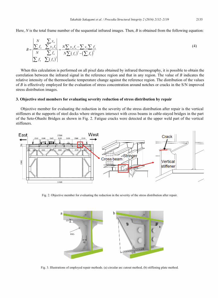
Objective member for evaluating the reduction in the severity of the stress distribution after repair is the vertical stiffeners at the supports of steel decks where stringers intersect with cross beams in cable-stayed bridges in the part of the Seto-Ohashi Bridges as shown in Fig. 2. Fatigue cracks were detected at the upper weld part of the vertical stiffeners.
Fig. 2. Objective member for evaluating the reduction in the severity of the stress distribution after repair.
a b
Fig. 3. Illustrations of employed repair methods. (a) circular arc cutout method, (b) stiffening plate method.
Takahide Sakagami et al. / Procedia Structural Integrity 2 (2016) 2132–2139 2135 Takahide Sakagami / Structural Integrity Procedia 00 (2016) 000–000 3
stress evaluation technique. Fatigue cracks were found in the steel structural members of the Seto-Ohashi Bridges at the 21st-year inspection. Several repair methods were investigated by FEM analyses and experimental studies at the site. Effectiveness of the employed repair methods were examined by nondestructive evaluation method based on the thermoelastic stress measurement.
2. Thermoelastic stress measurement
Dynamic stress change causes a very small temperature change under adiabatic conditions in a solid. This phenomenon is known as the thermoelastic effect and is described by Lord Kelvin’s equation, which relates the temperature change (T) to the sum of the changes in the principal stresses () under cyclic variable loading as follows.
p
T TC
(1)
: coefficient of thermal expansion : mass density Cp: specific heat at constant pressure T: absolute temperature The sum of the changes in the principal stresses () is obtained by measuring the temperature change (T) using
high-performance infrared thermography. As thermoelastic temperature changes are very small and sometimes hidden by the thermal noise of the infrared
camera, lock-in infrared thermography using reference signals synchronized with stress changes is commonly employed to improve the accuracy of stress measurements. The conventional thermoelastic stress measurement technique requires the lock-in algorithm with the reference loading signal extracted from the load cell or strain gauge for signal to noise ratio improvement. However, it is difficult to obtain a reference signal from steel bridges that are actively in service. Furthermore, the observed load signal contains irregular waveform components because of moving wheel loading by vehicles on the bridge. These problems cause difficulties for the use of conventional lock-in infrared thermography in the on-site thermoelastic stress measurement of steel bridges
Sakagami et al. (2005) developed a self-reference lock-in thermography technique that did not require any external reference signals and can be employed even under irregular waveform loading. In the self-reference lock-in thermography, a reference signal is constructed from a reference region that is arbitrarily set on the same sequential infrared images as those showing the thermoelastic temperature change. The distribution of the relative intensity of the thermoelastic temperature change against that in the reference region can then be obtained using the following least-squares approach developed by Lesniak et al. (1998), even under irregular waveform loading, provided that the temperature change in the reference region has a similar and in-phase waveform to that in the objective area under measurement.
Assume that a body is subjected to irregular waveform loading and the waveform is expressed as fn, the infrared signal in the objective region can then be approximated as follows:
n nY A Bf (2)
where A is an offset value, B is the influence coefficient of the reference and n is the frame number of the sequential infrared images. To calculate B, the sum of the squares of the deviations between Yn and the infrared signal yn obtained from the region, defined as follows, is minimized:
22
1
N
n nn
y Y
(3)
4 Takahide Sakagami / Structural Integrity Procedia 00 (2016) 000–000
Here, N is the total frame number of the sequential infrared images. Then, B is obtained from the following equation:
22
2
n
n n n n n n n
n n n
n n
N yf y f N y f y f
BN f N f f
f f
(4)
When this calculation is performed on all pixel data obtained by infrared thermography, it is possible to obtain the correlation between the infrared signal in the reference region and that in any region. The value of B indicates the relative intensity of the thermoelastic temperature change against the reference region. The distribution of the values of B is effectively employed for the evaluation of stress concentration around notches or cracks in the S/N improved stress distribution images.
3. Objective steel members for evaluating severity reduction of stress distribution by repair
Objective member for evaluating the reduction in the severity of the stress distribution after repair is the vertical stiffeners at the supports of steel decks where stringers intersect with cross beams in cable-stayed bridges in the part of the Seto-Ohashi Bridges as shown in Fig. 2. Fatigue cracks were detected at the upper weld part of the vertical stiffeners.
Fig. 2. Objective member for evaluating the reduction in the severity of the stress distribution after repair.
a b
Fig. 3. Illustrations of employed repair methods. (a) circular arc cutout method, (b) stiffening plate method.

2136 Takahide Sakagami et al. / Procedia Structural Integrity 2 (2016) 2132–2139 Takahide Sakagami / Structural Integrity Procedia 00 (2016) 000–000 5
a b
Fig. 4. Results of FEM analyses. (a) no repair, (b) circular arc cutout repair.
Two different repair methods, i.e., a circular arc cutout method and a stiffening plate method shown in Fig. 3 were examined. Both methods were intended to mitigate high stress concentration in the weld part located at the top of the stiffeners by transferring high stress to the arc cut out or the stiffening plate. Size of the cutout was determined by FEM analyses. FEM analysis results are shown in Fig. 4. It is found that high stress concentration points are observed at the at the upper weld parts of the vertical stiffeners. In contrast, after the circular arc cutout repair, stress concentration areas are transferred from the weld part to the edges of the circular arc.
At the portions where above repair methods were applied, fatigue cracks were propagated in eastern vertical stiffeners along the boxing welding sections as shown in Fig. 2. Length of the fatigue cracks was 20mm - 40mm. The repair works were conducted in the following three steps. First thermoelastic stress measurements around fatigue cracks were conducted before repair. Secondly each repair method was applied to vertical stiffeners with leaving cracks as they are. After that thermoelastic stress measurement was conducted to investigate the stress reduction effect of each repair method. Finally fatigue cracks were removed and the vertical stiffener was re-welded, and thermoelastic stress measurement was again conducted.
4. Thermoelastic stress measurement before and after repair
4.1. Measurement
Stress distributions on the vertical stiffeners were measured before the repair and after the each repair stage described in the foregoing paragraph. In each measurement, objective structure was loaded by the loading vehicle (200kN) driving on the traffic lane on the bridge. The thermoelastic stress measurement was conducted using the high-performance infrared camera with InSb infrared QVGA array detector with 20mK temperature resolution. The framing rate of infrared measurements was set to 157 Hz. From the temperature change observed by the infrared camera, change in the sum of principal stresses was calculated using Eq. (1). In this study the obtained sequential infrared data were processed using the self-reference lock-in technique to obtain S/N improved stress distribution images.
4.2. Measurement results for circular arc cutout repair
Experimental results of the thermoelastic stress measurement obtained for the circular arc cutout repair method are shown in Fig. 5. It is found from Fig. 5(a) that high stress concentration at the crack tip can be observed before the repair. On the other hand, it is found from Fig. 5(b) that the stress concentration is observed at the edge of circular arc after the circular arc cutout repair. The change in the sum of the principal stresses at maximum stress concentration point was reduced by 50% after the circular arc cutout repair. This experimental result is consistent with the FEM analysis as shown in Fig. 4. From Fig. 5(c), it can be seen that stress distribution obtained after the re-welding did not change so much. This experimental study clarified that the circular arc cutout repair method can transfer high stress concentration from the weld part at the top of the stiffener to the edge of circular arc where
6 Takahide Sakagami / Structural Integrity Procedia 00 (2016) 000–000
fatigue resistance is higher. Stress values measured by strain gauges are shown in Fig. 6. The figure shows the same trend as the thermoelastic stress measurement.
a
b
c
Fig. 5. Results of thermoelastic stress distribution measurement for circular arc cutout repair method. (a) before repair, (b) after circular arc cutout repair, (c) after fatigue crack removal and re-welding.
Fig. 6. Results of stress measurement by strain gauges obtained for circular arc cutout repair method.

Takahide Sakagami et al. / Procedia Structural Integrity 2 (2016) 2132–2139 2137 Takahide Sakagami / Structural Integrity Procedia 00 (2016) 000–000 5
a b
Fig. 4. Results of FEM analyses. (a) no repair, (b) circular arc cutout repair.
Two different repair methods, i.e., a circular arc cutout method and a stiffening plate method shown in Fig. 3 were examined. Both methods were intended to mitigate high stress concentration in the weld part located at the top of the stiffeners by transferring high stress to the arc cut out or the stiffening plate. Size of the cutout was determined by FEM analyses. FEM analysis results are shown in Fig. 4. It is found that high stress concentration points are observed at the at the upper weld parts of the vertical stiffeners. In contrast, after the circular arc cutout repair, stress concentration areas are transferred from the weld part to the edges of the circular arc.
At the portions where above repair methods were applied, fatigue cracks were propagated in eastern vertical stiffeners along the boxing welding sections as shown in Fig. 2. Length of the fatigue cracks was 20mm - 40mm. The repair works were conducted in the following three steps. First thermoelastic stress measurements around fatigue cracks were conducted before repair. Secondly each repair method was applied to vertical stiffeners with leaving cracks as they are. After that thermoelastic stress measurement was conducted to investigate the stress reduction effect of each repair method. Finally fatigue cracks were removed and the vertical stiffener was re-welded, and thermoelastic stress measurement was again conducted.
4. Thermoelastic stress measurement before and after repair
4.1. Measurement
Stress distributions on the vertical stiffeners were measured before the repair and after the each repair stage described in the foregoing paragraph. In each measurement, objective structure was loaded by the loading vehicle (200kN) driving on the traffic lane on the bridge. The thermoelastic stress measurement was conducted using the high-performance infrared camera with InSb infrared QVGA array detector with 20mK temperature resolution. The framing rate of infrared measurements was set to 157 Hz. From the temperature change observed by the infrared camera, change in the sum of principal stresses was calculated using Eq. (1). In this study the obtained sequential infrared data were processed using the self-reference lock-in technique to obtain S/N improved stress distribution images.
4.2. Measurement results for circular arc cutout repair
Experimental results of the thermoelastic stress measurement obtained for the circular arc cutout repair method are shown in Fig. 5. It is found from Fig. 5(a) that high stress concentration at the crack tip can be observed before the repair. On the other hand, it is found from Fig. 5(b) that the stress concentration is observed at the edge of circular arc after the circular arc cutout repair. The change in the sum of the principal stresses at maximum stress concentration point was reduced by 50% after the circular arc cutout repair. This experimental result is consistent with the FEM analysis as shown in Fig. 4. From Fig. 5(c), it can be seen that stress distribution obtained after the re-welding did not change so much. This experimental study clarified that the circular arc cutout repair method can transfer high stress concentration from the weld part at the top of the stiffener to the edge of circular arc where
6 Takahide Sakagami / Structural Integrity Procedia 00 (2016) 000–000
fatigue resistance is higher. Stress values measured by strain gauges are shown in Fig. 6. The figure shows the same trend as the thermoelastic stress measurement.
a
b
c
Fig. 5. Results of thermoelastic stress distribution measurement for circular arc cutout repair method. (a) before repair, (b) after circular arc cutout repair, (c) after fatigue crack removal and re-welding.
Fig. 6. Results of stress measurement by strain gauges obtained for circular arc cutout repair method.

2138 Takahide Sakagami et al. / Procedia Structural Integrity 2 (2016) 2132–2139 Takahide Sakagami / Structural Integrity Procedia 00 (2016) 000–000 7
4.3. Measurement results for stiffening plate method
Experimental results of the thermoelastic stress measurement obtained for the stiffening plate repair method are shown in Fig. 7. It is found from the figures that the high stress concentration at the crack tip was not mitigated even after the repair work was applied. It is found that the stiffening plate method did not transfer the high stress concentration from the top of the stiffener to the stiffening plate at this time.
a
b
c
Fig. 7. Results of thermoelastic stress distribution measurement for stiffening plate repair method. (a) before repair, (b) after stiffening plate repair, (c) after fatigue crack removal and re-welding.
5. Conclusions
This paper focused on the repair techniques for the members of steel bridge with fatigue cracks and the confirmation of reduction in the severity of the stress distribution around the repaired portion using thermoelastic stress evaluation technique. Two different repair methods were investigated. From the experimental investigations of the thermoelastic stress measurement, it is found that the stress concentration around the fatigue crack tip at the top of stiffener was mitigated by the circular arc cutout method, while the stiffening plate method did not work effectively for stress mitigation. It is found that the thermoelastic stress measurement is effective for the evaluation of the effectiveness of repair works in the bridge maintenance.
8 Takahide Sakagami / Structural Integrity Procedia 00 (2016) 000–000
Acknowledgements
The authors would like to acknowledge that research works shown in this paper were partly supported by a Grant-in-Aid for Scientific Research from the Japan Society for the Promotion of Science (B: 26289009), and Casio Science Foundation.
References
Lesniak, J., Boyce, B., Howenwater, G., 1998. Thermoelastic measurement under random loading. Proc. SEM Spring Conf. Soc. Exp. Mech., 504–507.
Sakagami, T., Nishimura, T., Kubo, S., 2005. Development of a self-reference lock-in thermography and its application to crack monitoring. Proc. SPIE, 5782, 379–387.
Sakagami, T., Izumi, Y., Kobayashi, Y., Mizokami, Y., Kawabata, S., 2014. Applications of infrared thermography for nondestructive testing of fatigue cracks in steel bridges. Proc. SPIE, 9105, 0S-1–0S-8.
Sakagami, T., 2015. Remote nondestructive evaluation technique using infrared thermography for fatigue cracks in steel bridges. Fatigue & Fracture of Engineering Materials & Structures, 38, 755-779.
Shiozawa, D., Inaba, K., Akai, A., Sakagami, T., 2014. Experimental study of relationship between energy dissipation and fatigue damage from observation of slip band by atomic force microscope. Advanced Mater. Res., 891, 606–611.

Takahide Sakagami et al. / Procedia Structural Integrity 2 (2016) 2132–2139 2139 Takahide Sakagami / Structural Integrity Procedia 00 (2016) 000–000 7
4.3. Measurement results for stiffening plate method
Experimental results of the thermoelastic stress measurement obtained for the stiffening plate repair method are shown in Fig. 7. It is found from the figures that the high stress concentration at the crack tip was not mitigated even after the repair work was applied. It is found that the stiffening plate method did not transfer the high stress concentration from the top of the stiffener to the stiffening plate at this time.
a
b
c
Fig. 7. Results of thermoelastic stress distribution measurement for stiffening plate repair method. (a) before repair, (b) after stiffening plate repair, (c) after fatigue crack removal and re-welding.
5. Conclusions
This paper focused on the repair techniques for the members of steel bridge with fatigue cracks and the confirmation of reduction in the severity of the stress distribution around the repaired portion using thermoelastic stress evaluation technique. Two different repair methods were investigated. From the experimental investigations of the thermoelastic stress measurement, it is found that the stress concentration around the fatigue crack tip at the top of stiffener was mitigated by the circular arc cutout method, while the stiffening plate method did not work effectively for stress mitigation. It is found that the thermoelastic stress measurement is effective for the evaluation of the effectiveness of repair works in the bridge maintenance.
8 Takahide Sakagami / Structural Integrity Procedia 00 (2016) 000–000
Acknowledgements
The authors would like to acknowledge that research works shown in this paper were partly supported by a Grant-in-Aid for Scientific Research from the Japan Society for the Promotion of Science (B: 26289009), and Casio Science Foundation.
References
Lesniak, J., Boyce, B., Howenwater, G., 1998. Thermoelastic measurement under random loading. Proc. SEM Spring Conf. Soc. Exp. Mech., 504–507.
Sakagami, T., Nishimura, T., Kubo, S., 2005. Development of a self-reference lock-in thermography and its application to crack monitoring. Proc. SPIE, 5782, 379–387.
Sakagami, T., Izumi, Y., Kobayashi, Y., Mizokami, Y., Kawabata, S., 2014. Applications of infrared thermography for nondestructive testing of fatigue cracks in steel bridges. Proc. SPIE, 9105, 0S-1–0S-8.
Sakagami, T., 2015. Remote nondestructive evaluation technique using infrared thermography for fatigue cracks in steel bridges. Fatigue & Fracture of Engineering Materials & Structures, 38, 755-779.
Shiozawa, D., Inaba, K., Akai, A., Sakagami, T., 2014. Experimental study of relationship between energy dissipation and fatigue damage from observation of slip band by atomic force microscope. Advanced Mater. Res., 891, 606–611.


![LIFE ASSESSMENT OF POWER PLANT BOILER …Figure 2. shows cracks resulted by corrosion-fatigue. Figure 2. A family of longitdinal cracks resulting from fluctuation in internal pressure[2]](https://img.pdfslide.us/doc/110x75/5e3c9af517fb8a5f226bd0c0/life-assessment-of-power-plant-boiler-figure-2-shows-cracks-resulted-by-corrosion-fatigue.jpg)