Embed Size (px)
Citation preview
Non-Membrane Disinfection
Sensors Instruction Manual
Five Boynton Road Hopping Brook Park Holliston, MA 01746 USA
TEL: 508-429-1110 WEB: www.walchem.com
Disinfection Sensors
W A L C H E M
IWAKI America Inc.
Notice
© 2018 WALCHEM, Iwaki America Inc. (hereinafter “Walchem”)
Five Boynton Road, Holliston, MA 01746 USA
(508) 429-1110
All Rights Reserved
Printed in USA
Proprietary Material The information and descriptions contained herein are the property of
WALCHEM. Such information and descriptions may not be copied or
reproduced by any means, or disseminated or distributed without the
express prior written permission of WALCHEM, Five Boynton Road,
Holliston, MA 01746.
Statement of Limited Warranty WALCHEM warrants equipment of its manufacture, and bearing its identification
to be free from defects in workmanship and material for a period of 24 months
for electronics and 12 months for mechanical parts and electrodes from date of
delivery from the factory or authorized distributor under normal use and service
and otherwise when such equipment is used in accordance with instructions
furnished by WALCHEM and for the purposes disclosed in writing at the time of
purchase, if any. WALCHEM’s liability under this warranty shall be limited to
replacement or repair, F.O.B. Holliston, MA U.S.A. of any defective equipment
or part which, having been returned to WALCHEM, transportation charges
prepaid, has been inspected and determined by WALCHEM to be defective.
Replacement elastomeric parts and glass components are expendable and are not
covered by any warranty.
THIS WARRANTY IS IN LIEU OF ANY OTHER WARRANTY, EITHER
EXPRESS OR IMPLIED, AS TO DESCRIPTION, QUALITY,
MERCHANTABILITY, and FITNESS FOR ANY PARTICULAR PURPOSE OR
USE, OR ANY OTHER MATTER.
P/N 180560.F March 2018
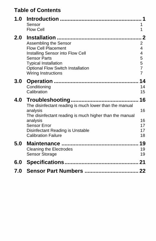
Table of Contents
1.0 Introduction ..................................................... 1 Sensor 1 Flow Cell 1
2.0 Installation ....................................................... 2 Assembling the Sensor 2 Flow Cell Placement 4 Installing Sensor into Flow Cell 4 Sensor Parts 5 Typical Installation 5 Optional Flow Switch Installation 7 Wiring Instructions 7
3.0 Operation ....................................................... 14 Conditioning 14 Calibration 15
4.0 Troubleshooting ............................................ 16 The disinfectant reading is much lower than the manual analysis 16 The disinfectant reading is much higher than the manual analysis 16 Sensor Error 17 Disinfectant Reading is Unstable 17 Calibration Failure 18
5.0 Maintenance .................................................. 19 Cleaning the Electrodes 19 Sensor Storage 19
6.0 Specifications ................................................ 21
7.0 Sensor Part Numbers ................................... 22
1
1.0 Introduction The Walchem non-membrane chlorine and chlorine dioxide sensors
consist of an amperometric sensor assembly, cable and a flow cell.
Assembly of these parts is required, so please read these instructions
carefully. The sensor is capable of measuring the disinfectant in drinking
water or drinking water quality water.
Sensor The sensor assembly includes the sensor body, a 50-ml bottle of electrolyte
fill solution, and special abrasive emery paper. Make sure that all parts are
included.
The sensors are open (not-membrane covered) amperometric 3-electrode
types. The measuring and counter electrode are in direct contact with the
measuring water. The reference electrode is separated from the measuring
water by a housing which contains an electrolyte. Together with the
electrolyte, an electrical signal is generated at the measuring electrode
which is proportional to the concentration of the disinfectant, and
amplified by the electronics of the sensor. The measuring signal is
temperature compensated.
Flow Cell The flow cell consists of a translucent flow cell body, mounting nut and o-
ring, washer set and o-ring. Make sure that all parts are included.
The flow cell is required. The sensor will not read accurately if it is not
installed in the flow cell, with a steady flow rate between 20 and 100 liters
per hour, at an operating pressure of 8 atmospheres or less.
2
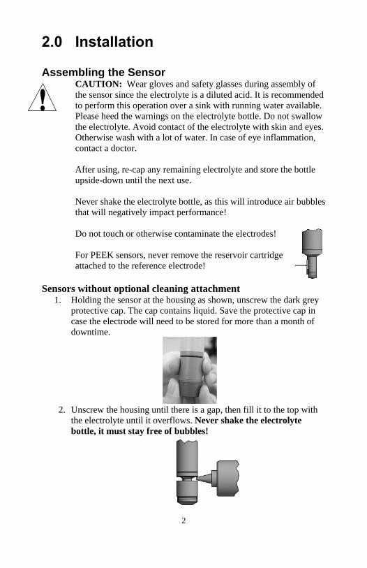
2.0 Installation Assembling the Sensor
CAUTION: Wear gloves and safety glasses during assembly of
the sensor since the electrolyte is a diluted acid. It is recommended
to perform this operation over a sink with running water available.
Please heed the warnings on the electrolyte bottle. Do not swallow
the electrolyte. Avoid contact of the electrolyte with skin and eyes.
Otherwise wash with a lot of water. In case of eye inflammation,
contact a doctor.
After using, re-cap any remaining electrolyte and store the bottle
upside-down until the next use.
Never shake the electrolyte bottle, as this will introduce air bubbles
that will negatively impact performance!
Do not touch or otherwise contaminate the electrodes!
For PEEK sensors, never remove the reservoir cartridge
attached to the reference electrode!
Sensors without optional cleaning attachment 1. Holding the sensor at the housing as shown, unscrew the dark grey
protective cap. The cap contains liquid. Save the protective cap in
case the electrode will need to be stored for more than a month of
downtime.
2. Unscrew the housing until there is a gap, then fill it to the top with
the electrolyte until it overflows. Never shake the electrolyte
bottle, it must stay free of bubbles!
3
3. SLOWLY screw on the housing until it is hand tight. Be prepared
for some electrolyte solution to squeeze out.
4. Rinse your hands, the sensor, and all surfaces contaminated with
electrolyte solution with running water. Check the sensor for leaks.
5. Push the cable onto the end of the sensor, aligning the pins with the
holes. Turn the connector until hand tight to seal the cable
connection.
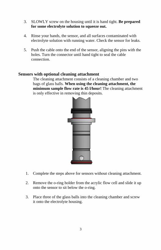
Sensors with optional cleaning attachment The cleaning attachment consists of a cleaning chamber and two
bags of glass balls. When using the cleaning attachment, the
minimum sample flow rate is 45 l/hour! The cleaning attachment
is only effective in removing thin deposits.
1. Complete the steps above for sensors without cleaning attachment.
2. Remove the o-ring holder from the acrylic flow cell and slide it up
onto the sensor to sit below the o-ring.
3. Place three of the glass balls into the cleaning chamber and screw
it onto the electrolyte housing.
4
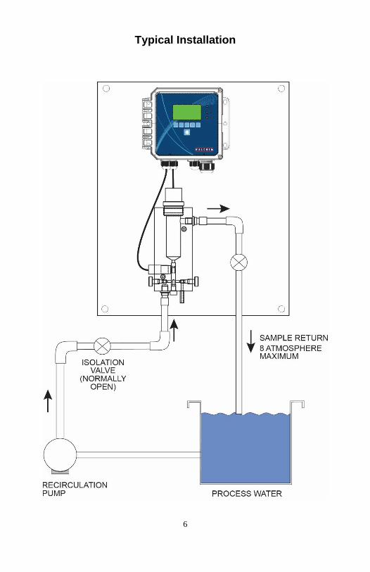
Flow Cell Placement Instructions for mounting the sensor into the process can vary greatly with
the circumstances that are encountered in your application. Here are some
general guidelines to assist you. Refer also to the typical installation
drawings.
The flow cell should be placed on the discharge side of a circulation pump
or downhill from a gravity feed. Flow into the cell must come from the
bottom side that has the 8 mm OD tubing x ¼” straight thread fitting
installed.
The outlet of the flow cell must be plumbed to open atmosphere unless the
system pressure is at or below 8 atmospheres. If the flow through the line
cannot be stopped to allow for cleaning and calibration of the sensor, then it
should be placed in a by-pass line with isolation valves to allow for sensor
removal. Install the sensor vertically, with the measuring surface pointing
down, at least 5 degrees above horizontal. (Refer to Installation drawing)
Flow rate regulation must be done upstream from the sensor, because any
flow restriction downstream can increase the pressure above the rated value.
The acrylic flow cell has a flow regulator knob on the lower left hand side.
The sensor should be installed in an area where there is good solution
movement and where it will respond rapidly to chemical additions. The
placement of the sensor relative to the placement of chemical
replenishment, along with the quality of the mixing, and the replenishment
chemical flow rate are critical to accurate process control.
To avoid biological growth on the electrodes, which can block
measurement, never leave the sensor in water without oxidant for longer
than 24 hours, unless using the optional cleaning attachment.
Installing Sensor into Flow Cell 1. For sensors without the cleaning attachment, unscrew the 1 ¼” fitting
from the acrylic flow cell. Insert the sensor as shown below.
Push the 1 ¼” fitting over the sensor and fasten it tightly. Make sure that
the sensor is tightly fastened in place, otherwise it may be pushed out of
the flow cell when it is under pressure, or leaks can occur. 2. For sensors with the cleaning attachment, unscrew the 1 ¼” fitting from
the acrylic flow cell. Insert the sensor with mounted cleaning attachment
and o-ring holder into the flow cell by turning it CLOCKWISE until the
o-ring holder is snug (turning CCW can loosen the electrolyte housing
5
and/or cleaning attachment). Make sure that the large black o-ring is
located between the o-ring holder and the flow cell, as shown below.
Push the 1 ¼” fitting over the sensor and fasten it tightly. Make sure that
the sensor is tightly fastened in place, otherwise it may be pushed out of
the flow cell when it is under pressure, or leaks can occur.
3. To supply a sample, first open the water outlet valve. Then open slowly
the measuring water supply valve. The minimum flow rate is 45
liters/hour when using the cleaning attachment, 20 liters/hour without.
The acrylic flow cell has a flow regulator knob on the lower left hand
side. Avoid installations that allow air bubbles to enter the measuring
water.
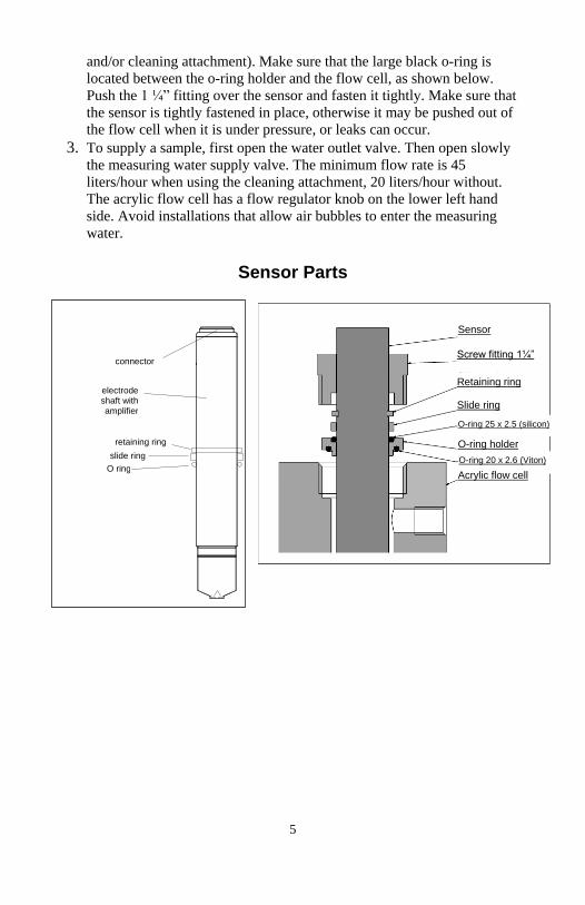
Sensor Parts
O ring
connector
electrode shaft with amplifier
retaining ring
slide ring
Sensor
Screw fitting 1¼”
Retaining ring
Slide ring
O-ring holder
O-ring 20 x 2.6 (Viton)
Acrylic flow cell
O-ring 25 x 2.5 (silicon)
6
Typical Installation
7
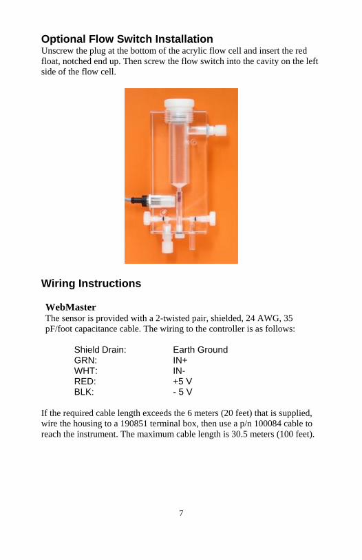
Optional Flow Switch Installation Unscrew the plug at the bottom of the acrylic flow cell and insert the red
float, notched end up. Then screw the flow switch into the cavity on the left
side of the flow cell.
Wiring Instructions
WebMaster The sensor is provided with a 2-twisted pair, shielded, 24 AWG, 35
pF/foot capacitance cable. The wiring to the controller is as follows:
Shield Drain: Earth Ground GRN: IN+ WHT: IN- RED: +5 V BLK: - 5 V
If the required cable length exceeds the 6 meters (20 feet) that is supplied,
wire the housing to a 190851 terminal box, then use a p/n 100084 cable to
reach the instrument. The maximum cable length is 30.5 meters (100 feet).
8
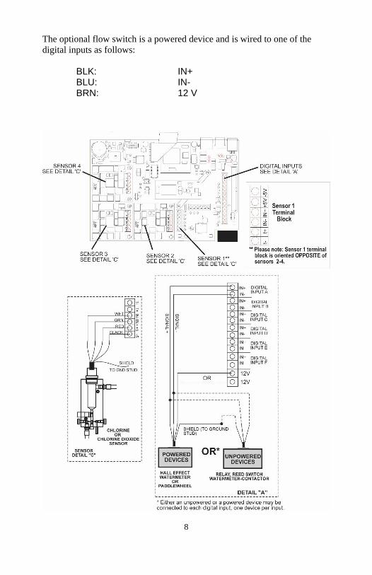
The optional flow switch is a powered device and is wired to one of the
digital inputs as follows:
BLK: IN+ BLU: IN- BRN: 12 V
9
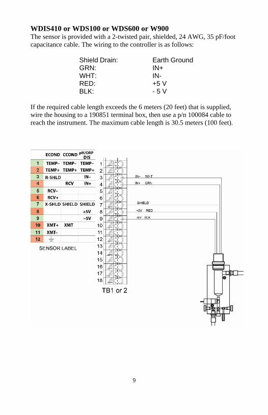
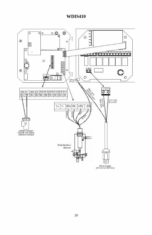
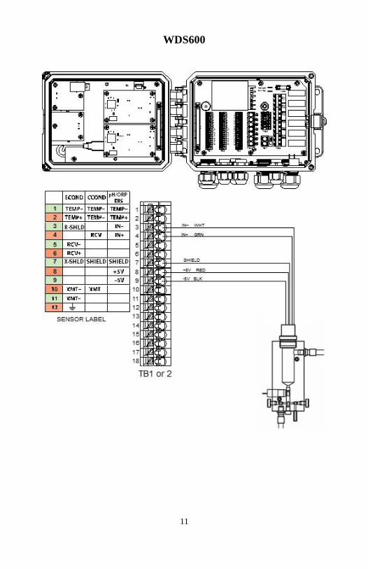
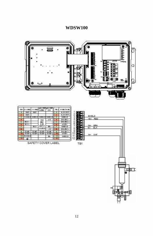
WDIS410 or WDS100 or WDS600 or W900 The sensor is provided with a 2-twisted pair, shielded, 24 AWG, 35 pF/foot
capacitance cable. The wiring to the controller is as follows:
Shield Drain: Earth Ground GRN: IN+ WHT: IN- RED: +5 V BLK: - 5 V
If the required cable length exceeds the 6 meters (20 feet) that is supplied,
wire the housing to a 190851 terminal box, then use a p/n 100084 cable to
reach the instrument. The maximum cable length is 30.5 meters (100 feet).
10
WDIS410
11
WDS600
12
WDSW100
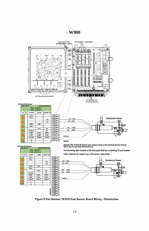
13
W900
14
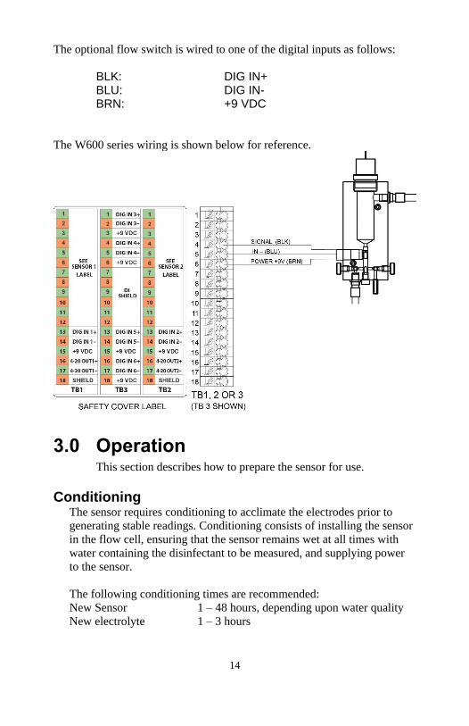
The optional flow switch is wired to one of the digital inputs as follows:
BLK: DIG IN+ BLU: DIG IN- BRN: +9 VDC
The W600 series wiring is shown below for reference.
3.0 Operation This section describes how to prepare the sensor for use.
Conditioning The sensor requires conditioning to acclimate the electrodes prior to
generating stable readings. Conditioning consists of installing the sensor
in the flow cell, ensuring that the sensor remains wet at all times with
water containing the disinfectant to be measured, and supplying power
to the sensor.
The following conditioning times are recommended:
New Sensor 1 – 48 hours, depending upon water quality
New electrolyte 1 – 3 hours
15
Calibration The frequency of calibration is a function of many factors. These factors
include:
1. The accuracy required by the application.
2. The value of the off-specification product versus the cost of
calibration.
3. The coating or abrasive nature of the application.
4. The stability of the sensor and controller as a system.
The frequency of calibration is really determined by experience. At a
new installation, calibration might initially be checked every day by
comparing the controller reading to a DPD test or other manual analysis
and logging the results. If the reading drifts off significantly in one
direction you should consider calibrating. Resist the temptation to
calibrate to correct for small errors that may be a result of normal
variations in the test methods.
A calibration MUST be performed on initial installation, or after
cleaning the electrodes, or after replacing the electrolyte. A sensor
installed in clean water can hold its calibration for several months.
DO NOT attempt to perform a calibration until the following conditions
have been met:
1. The sensor has been conditioned as described above.
2. The sensor has equilibrated to the temperature of the water (for the
zero calibration) or the sample (for the 1 point process calibration).
Zero Calibration 1. Remove the sensor from the flow cell and place it in a beaker of clean,
oxidizer-free water.
2. Allow the sensor 1 hour to equilibrate.
3. Go to the Zero Calibration menu of the controller. Refer to the controller
instructions.
4. Stir the water with the sensor until the mV reading is stable for at least 5
minutes.
5. When the reading is stable, continue to the final steps of the calibration.
6. Return the sensor to the flow cell and check for leaks.
One Point Process Calibration
1. Ensure that the sensor is conditioned and equilibrated to the temperature
of the sample.
2. Ensure that the sample flow rate is between 20 and 100 liters/hour. The
acrylic flow cell has a flow regulator knob on the lower left hand side.
16
3. Perform a DPD test or other manual analysis on the sample water.
4. Go to the One Point Process Calibration menu of the controller. Refer to
the controller instructions.
5. When the reading is stable, continue to the final steps of the calibration.
NOTE: Disinfectant concentration can change rapidly in the sample!
Minimize the time between performing the DPD test or manual analysis and
finishing the calibration!
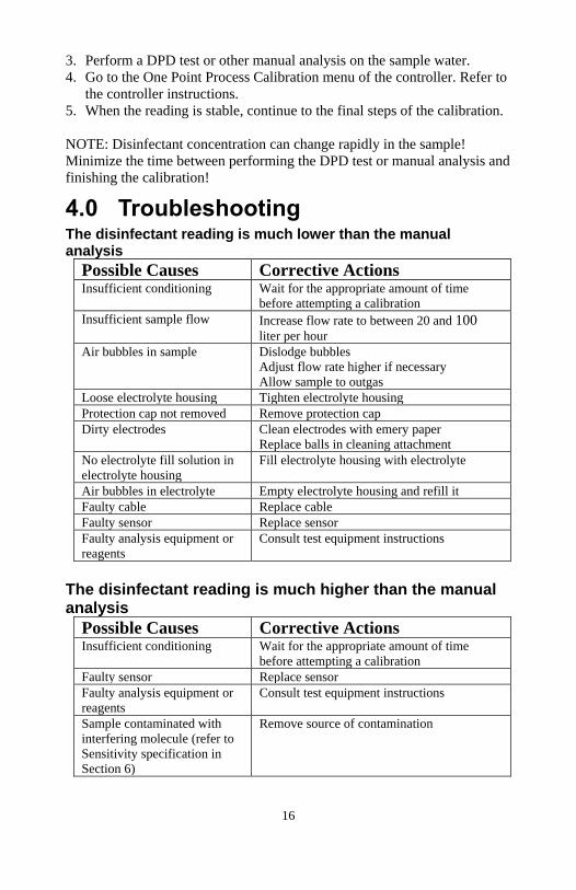
4.0 Troubleshooting The disinfectant reading is much lower than the manual analysis
Possible Causes Corrective Actions Insufficient conditioning Wait for the appropriate amount of time
before attempting a calibration
Insufficient sample flow Increase flow rate to between 20 and 100 liter per hour
Air bubbles in sample Dislodge bubbles
Adjust flow rate higher if necessary
Allow sample to outgas
Loose electrolyte housing Tighten electrolyte housing
Protection cap not removed Remove protection cap
Dirty electrodes Clean electrodes with emery paper
Replace balls in cleaning attachment
No electrolyte fill solution in
electrolyte housing
Fill electrolyte housing with electrolyte
Air bubbles in electrolyte Empty electrolyte housing and refill it
Faulty cable Replace cable
Faulty sensor Replace sensor
Faulty analysis equipment or
reagents
Consult test equipment instructions
The disinfectant reading is much higher than the manual analysis
Possible Causes Corrective Actions Insufficient conditioning Wait for the appropriate amount of time
before attempting a calibration
Faulty sensor Replace sensor
Faulty analysis equipment or
reagents
Consult test equipment instructions
Sample contaminated with
interfering molecule (refer to
Sensitivity specification in
Section 6)
Remove source of contamination
17
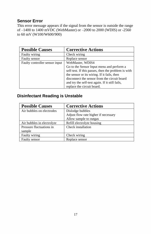
Sensor Error This error message appears if the signal from the sensor is outside the range
of –1400 to 1400 mVDC (WebMaster) or –2000 to 2000 (WDIS) or -2560
to 60 mV (W100/W600/900)
Possible Causes Corrective Actions Faulty wiring Check wiring
Faulty sensor Replace sensor
Faulty controller sensor input WebMaster, WDIS4
Go to the Sensor Input menu and perform a
self-test. If this passes, then the problem is with
the sensor or its wiring. If it fails, then
disconnect the sensor from the circuit board
and try the self-test again. If it still fails,
replace the circuit board.
Disinfectant Reading is Unstable
Possible Causes Corrective Actions Air bubbles on electrodes Dislodge bubbles
Adjust flow rate higher if necessary
Allow sample to outgas
Air bubbles in electrolyte Refill electrolyte housing
Pressure fluctuations in
sample
Check installation
Faulty wiring Check wiring
Faulty sensor Replace sensor
18
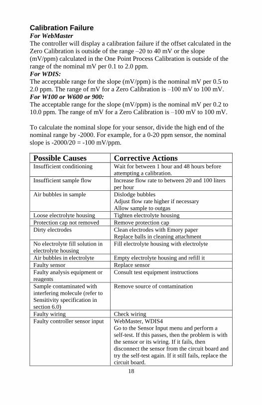
Calibration Failure For WebMaster
The controller will display a calibration failure if the offset calculated in the
Zero Calibration is outside of the range –20 to 40 mV or the slope
(mV/ppm) calculated in the One Point Process Calibration is outside of the
range of the nominal mV per 0.1 to 2.0 ppm.
For WDIS:
The acceptable range for the slope (mV/ppm) is the nominal mV per 0.5 to
2.0 ppm. The range of mV for a Zero Calibration is –100 mV to 100 mV.
For W100 or W600 or 900:
The acceptable range for the slope (mV/ppm) is the nominal mV per 0.2 to
10.0 ppm. The range of mV for a Zero Calibration is –100 mV to 100 mV.
To calculate the nominal slope for your sensor, divide the high end of the
nominal range by -2000. For example, for a 0-20 ppm sensor, the nominal
slope is -2000/20 = -100 mV/ppm.
Possible Causes Corrective Actions Insufficient conditioning Wait for between 1 hour and 48 hours before
attempting a calibration.
Insufficient sample flow Increase flow rate to between 20 and 100 liters
per hour
Air bubbles in sample Dislodge bubbles
Adjust flow rate higher if necessary
Allow sample to outgas
Loose electrolyte housing Tighten electrolyte housing
Protection cap not removed Remove protection cap
Dirty electrodes Clean electrodes with Emory paper
Replace balls in cleaning attachment
No electrolyte fill solution in
electrolyte housing
Fill electrolyte housing with electrolyte
Air bubbles in electrolyte Empty electrolyte housing and refill it
Faulty sensor Replace sensor
Faulty analysis equipment or
reagents
Consult test equipment instructions
Sample contaminated with
interfering molecule (refer to
Sensitivity specification in
section 6.0)
Remove source of contamination
Faulty wiring Check wiring
Faulty controller sensor input WebMaster, WDIS4
Go to the Sensor Input menu and perform a
self-test. If this passes, then the problem is with
the sensor or its wiring. If it fails, then
disconnect the sensor from the circuit board and
try the self-test again. If it still fails, replace the
circuit board.
19
5.0 Maintenance The sections below describes normal maintenance.
See section 4.0 Troubleshooting for assistance in determining when
maintenance may be required.
Cleaning the Electrodes It is recommended to clean the electrodes every 4 – 12 weeks or sooner if
calibration is impossible due to unstable or low values are displayed.
Remove the sensor from the flow cell by first closing the water supply
valve, then the water discharge valve, then unscrewing the 1 ¼” fitting. If
the optional cleaning attachment is present, pull the sensor out while turning
it in a CLOCKWISE direction.
Dry the outside of the sensor with a clean paper towel. If necessary hold the
electrolyte housing tight to unscrew the cleaning attachment.
Use the emery paper supplied to clean the electrodes. Do NOT move the
emery paper from one electrode to the other! Then put the sensor into
operation again.
If the sensor still displays unstable or too low values, the electrolyte has to
be changed as described in Section 2. It is recommended to change the
electrolyte every 3 – 6 months.
If the electrodes are dirty and the optional cleaning attachment is being
used, it is possible that the cleaning balls need to be replaced.
Sensor Storage
The sensor may be stored for up to one month in the flow cell assuming
that the membrane is always kept submerged in water.
An unused sensor, still in the box with protective cap, may be stored up
to 1 year if the ambient temperature is above freezing.
For long term storage, up to 3 years, follow this procedure:
CAUTION: Wear gloves and safety glasses during disassembly of the
sensor since the electrolyte is a diluted acid. It is recommended to
perform this operation over a sink with running water available.
20
Please heed the warnings on the electrolyte bottle. Do not swallow the
electrolyte. Avoid contact of the electrolyte with skin and eyes.
Otherwise wash with a lot of water. In case of eye inflammation,
contact a doctor.
To store the sensor unscrew the electrolyte housing.
Rinse the electrolyte housing and the electrode finger in clean water
and dry in a dust-free location.
Replace the protective cap onto the electrolyte housing.
Loosely screw the electrolyte housing with protective cap onto the
electrode shaft to protect the electrodes.
When putting the sensor back into operation after storage, the
electrodes must be cleaned with the emery paper.
21
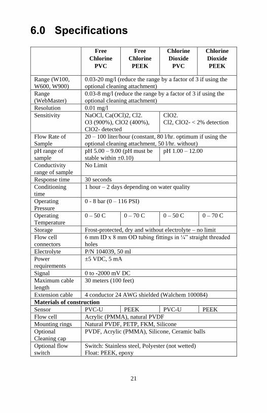
6.0 Specifications
Free
Chlorine
PVC
Free
Chlorine
PEEK
Chlorine
Dioxide
PVC
Chlorine
Dioxide
PEEK
Range (W100,
W600, W900)
0.03-20 mg/l (reduce the range by a factor of 3 if using the
optional cleaning attachment)
Range
(WebMaster)
0.03-8 mg/l (reduce the range by a factor of 3 if using the
optional cleaning attachment)
Resolution 0.01 mg/l
Sensitivity NaOCl, Ca(OCl)2, Cl2.
O3 (900%), ClO2 (400%),
ClO2- detected
ClO2.
Cl2, ClO2- < 2% detection
Flow Rate of
Sample
20 – 100 liter/hour (constant, 80 l/hr. optimum if using the
optional cleaning attachment, 50 l/hr. without)
pH range of
sample
pH 5.00 – 9.00 (pH must be
stable within ±0.10)
pH 1.00 – 12.00
Conductivity
range of sample
No Limit
Response time 30 seconds
Conditioning
time
1 hour – 2 days depending on water quality
Operating
Pressure
0 - 8 bar (0 – 116 PSI)
Operating
Temperature
0 – 50 C 0 – 70 C 0 – 50 C 0 – 70 C
Storage Frost-protected, dry and without electrolyte – no limit
Flow cell
connectors
6 mm ID x 8 mm OD tubing fittings in ¼” straight threaded
holes
Electrolyte P/N 104039, 50 ml
Power
requirements
±5 VDC, 5 mA
Signal 0 to -2000 mV DC
Maximum cable
length
30 meters (100 feet)
Extension cable 4 conductor 24 AWG shielded (Walchem 100084)
Materials of construction
Sensor PVC-U PEEK PVC-U PEEK
Flow cell Acrylic (PMMA), natural PVDF
Mounting rings Natural PVDF, PETP, FKM, Silicone
Optional
Cleaning cap
PVDF, Acrylic (PMMA), Silicone, Ceramic balls
Optional flow
switch
Switch: Stainless steel, Polyester (not wetted)
Float: PEEK, epoxy
22
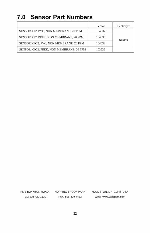
7.0 Sensor Part Numbers
Sensor Electrolyte
SENSOR, Cl2, PVC, NON MEMBRANE, 20 PPM 104037
104039 SENSOR, Cl2, PEEK, NON MEMBRANE, 20 PPM 104030
SENSOR, ClO2, PVC, NON MEMBRANE, 20 PPM 104038
SENSOR, ClO2, PEEK, NON MEMBRANE, 20 PPM 103939
FIVE BOYNTON ROAD HOPPING BROOK PARK HOLLISTON, MA 01746 USA
TEL: 508-429-1110 FAX: 508-429-7433 Web: www.walchem.com