Embed Size (px)
Citation preview

AFFILIATION LOGO
Non Linear Distortion and Dynamic Range IssuesNon Linear Distortion and Dynamic Range Issues
in the Design Of Microwave Electronics for in the Design Of Microwave Electronics for
Communication and Remote Sensing SystemsCommunication and Remote Sensing Systems
Alberto Alberto SantarelliSantarelli
Short course on:
RF electronics for wireless communicationand remote sensing systems
Scuola di Dottorato in Scienze ed Ingegneria dell'InformazioneDottorato di Ricerca in Ingegneria Elettronica Informatica e delle Telecomunicazioni
13th, 14th and 20th July 2010, Facoltà di Ingegneria, Viale Risorgimento 2, Bologna

AFFILIATION LOGO
A. Santarelli - Non linear distortion and dynamic range issues in the design of microwave electronics for communication and remote sensing systems – 14th July, 2010 2
SummarySummary
• Brief Overview of Wireless Systems
• Wireless T/R Front End Design Issues
• Non linear distortion, noise and dynamic-range issues in building blocks of wireless communication and remote sensing systems.
• Trade-off issues between nonlinear distortion, output power and power added efficiency in the design/optimization of microwave power amplifiers
• Basics of new generation electron devices for low-distortion, high-dynamic-range microwave circuit design.

AFFILIATION LOGO
A. Santarelli - Non linear distortion and dynamic range issues in the design of microwave electronics for communication and remote sensing systems – 14th July, 2010 3
Wireless Systems Overview (I)Wireless Systems Overview (I)
Wireless Cellular Telephone Network (Typ. Freq. : 950, 1800, 2100 MHz)
• (2G) GSM (mod. GMSK) - EDGE (mod. GMSK/8-PSK)
• (3G) UMTS (mod. QPSK)
– e.g. W-CDMA provides HSPA up to 7Mbs
– Freq. Band 5MHz
• (3GPP) LTE (mod. QPSK, 16-QAM, 64-QAM)
– expected cell data rates of over 300 Mbps
– Freq. Band up to 20 MHz
• (4G) IP-based, Software Defined Radio (SDR), Cognitive Radio (CR)

AFFILIATION LOGO
A. Santarelli - Non linear distortion and dynamic range issues in the design of microwave electronics for communication and remote sensing systems – 14th July, 2010 4
Wireless Cellular Telephone NetworkWireless Cellular Telephone Network
• Downlink (from BTS to Handset)
• Uplink (from Handset to BTS)
Base Terminal Station (BTS)
Different specs and
technologies used for uplink
and downlink…
e.g. 16-QAM - S/Nreq=11dB
Pout = 43 dBm
e.g. QPSK - S/Nreq = 5dBPout = 23 dBm
Fig. from Ref.[1]
DL
UL

AFFILIATION LOGO
A. Santarelli - Non linear distortion and dynamic range issues in the design of microwave electronics for communication and remote sensing systems – 14th July, 2010 5
Wireless Systems Overview (II)Wireless Systems Overview (II)
Wireless Local/Personal Area Network (WLAN/WPAN)
WiFi• OFDM with subcarriers mod. PSK or QAM)
• based on the IEEE 802.11 standards
• Data rate up to 54 Mbit/s
• Freq.: 2.4 GHz, 5 GHz, Bandwidth up to 22 MHz
WiMax• based on the IEEE 802.16 standard
• Multi-user channel access techniques such as OFDMA
• Peak data rates of 144 Mbit/s in downlink and 35 Mbit/s in uplink (802.16e)
• Freq. 2.3–2.5 GHz and the 3.4–3.5 GHz, Bandwidths up to 20 MHz
MIMO channels available (multiple TX/RX antennas, spatial diversity)

AFFILIATION LOGO
A. Santarelli - Non linear distortion and dynamic range issues in the design of microwave electronics for communication and remote sensing systems – 14th July, 2010 6
Wireless Systems Overview (III)Wireless Systems Overview (III)
Wireless Sensor Networks
• Spatially distributed autonomous sensors
• Equipped with a radio transceiveror other wireless communications devices
• Small dimensions, low-power consumption,low data rate, secure networking
• Typically based on theIEEE 802.15.4 standard (WPAN)
e.g. ZigBee in ISM radio bands and 2.4GHz
Super Node
Links to Other networks or
Similar Super Nodes
Motes
External Memory
Dig
ital I/O
port
s
Radio Transceiver
Analo
g I
/O P
ort
s
Microcontroller
A/D
D/A
Sensor
Sensor
External Memory
Dig
ital I/O
port
s
Radio Transceiver
Analo
g I
/O P
ort
s
Microcontroller
A/D
D/A
Microcontroller
A/D
D/A
Sensor
Sensor
Mote
Power Supply

AFFILIATION LOGO
A. Santarelli - Non linear distortion and dynamic range issues in the design of microwave electronics for communication and remote sensing systems – 14th July, 2010 7
Wireless Systems Overview (IV)Wireless Systems Overview (IV)
Back-Haul – Terrestrial and Satellite Communications
• Point-to-Point Terrestrial or via-Satellite Microwave Radio Links(e.g. connecting Base Stations)
– dedicated high-capacitive terrestrial radio links at 38 GHz (mod. PSK/QAM)
• Point-to-Multipoint Microwave Access Technologies(broadband, fixed wireless, point-to-multipoint technology)
– WiMax
– Local Multipoint Distribution Service (LMDS) at 28-29 GHz (PSK/QAM)

AFFILIATION LOGO
A. Santarelli - Non linear distortion and dynamic range issues in the design of microwave electronics for communication and remote sensing systems – 14th July, 2010 8
Wireless Systems Overview (V)Wireless Systems Overview (V)
Not only networks…
Satellite Remote Sensing and Communication
• Synthetic Aperture Radars
• Altimeters and radiometer applications
• Radioastronomy
• Satellite Radio Links for video, audio and data broadcasting (DVB-S/S2) and Internet Access at 12GHz (downlink) and 18 GHz (uplink)(mod. BPSK, 16APSK and 32APSK)
Frequency Bands: C – X – Ku and beyond…Reliability issues…

AFFILIATION LOGO
A. Santarelli - Non linear distortion and dynamic range issues in the design of microwave electronics for communication and remote sensing systems – 14th July, 2010 9
Basic Building Blocks of RF FrontBasic Building Blocks of RF Front--EndsEnds
• Power Amplifier (PA) – provides signal power amplification just before the transmitting antenna
• Low Noise Amplifier (LNA) – provides amplification just after the receiving antenna by introducing minimal S/N degradation
• Mixer – provides up and down frequency conversion of signals
• Local Oscillator – provides sinusoidal waveform for carrier generation
• Frequency Synthesizer – Provides stable and programmable carrier generation and recovery
• Linear Filters and Phase Shifters– for band and channel selection, image rejection, IQ modulation, etc.
• Duplexer - allows using a single antenna for TX/RX

AFFILIATION LOGO
A. Santarelli - Non linear distortion and dynamic range issues in the design of microwave electronics for communication and remote sensing systems – 14th July, 2010 10
DuplexingDuplexing
• Single antenna for RX and TX
• Time Division Duplexing (TDD) vs. Frequency Division Duplexing (FDD)
• RX has to be isolated from high power generated by HPA (otherwise: LNA desensitisation)
Half-duplex
Full-
duplex
Figs. from Ref. 2
FDD

AFFILIATION LOGO
A. Santarelli - Non linear distortion and dynamic range issues in the design of microwave electronics for communication and remote sensing systems – 14th July, 2010 11
MixerMixer
( ) cosLO LO LO
v t V tω= ( ) cosS S S
v t V tω=
( ) ( )( ) cos cos2 2
out LO S LO S LO S LO S
A Av t V V t V V tω ω ω ω= + + −
The mixer ideally executes a perfect
multiplication of two input signals vA, vB
The Mixer provides Frequency Conversion
Up-conversion Down-conversion
( )LO
v t
( )S
v t ( )out
v t
( ) ( ) ( )out LO S
v t A v t v t= ⋅ ⋅
• Actual Mixers suffer from noise and distortion

AFFILIATION LOGO
A. Santarelli - Non linear distortion and dynamic range issues in the design of microwave electronics for communication and remote sensing systems – 14th July, 2010 12
Example of a Microwave T/R FrontExample of a Microwave T/R Front--EndEnd
Fig. from Ref. 2
Lucent Tech. GSM Transceiver

AFFILIATION LOGO
A. Santarelli - Non linear distortion and dynamic range issues in the design of microwave electronics for communication and remote sensing systems – 14th July, 2010 13
Typical Trends in T/R FrontTypical Trends in T/R Front--End ArchitecturesEnd Architectures
• ADC and DAC progressively shift towards the antenna(Software Defined Radio)
• Reconfigurable building blocks(“frequency-agile” RF components and systems)
� Digital RF circuits
� Analog RF circuitswith digital control(e.g. with use ofRF-MEMS)
• High-efficiencyPA schemes(Doherty Amplifiers,Class-S Amplifiers,Envelope Tracking,…)
Fig. from Ref. 1Linearity ??? PA Linearization techniques
AFFILIATION LOGO
A. Santarelli - Non linear distortion and dynamic range issues in the design of microwave electronics for communication and remote sensing systems – 14th July, 2010 14
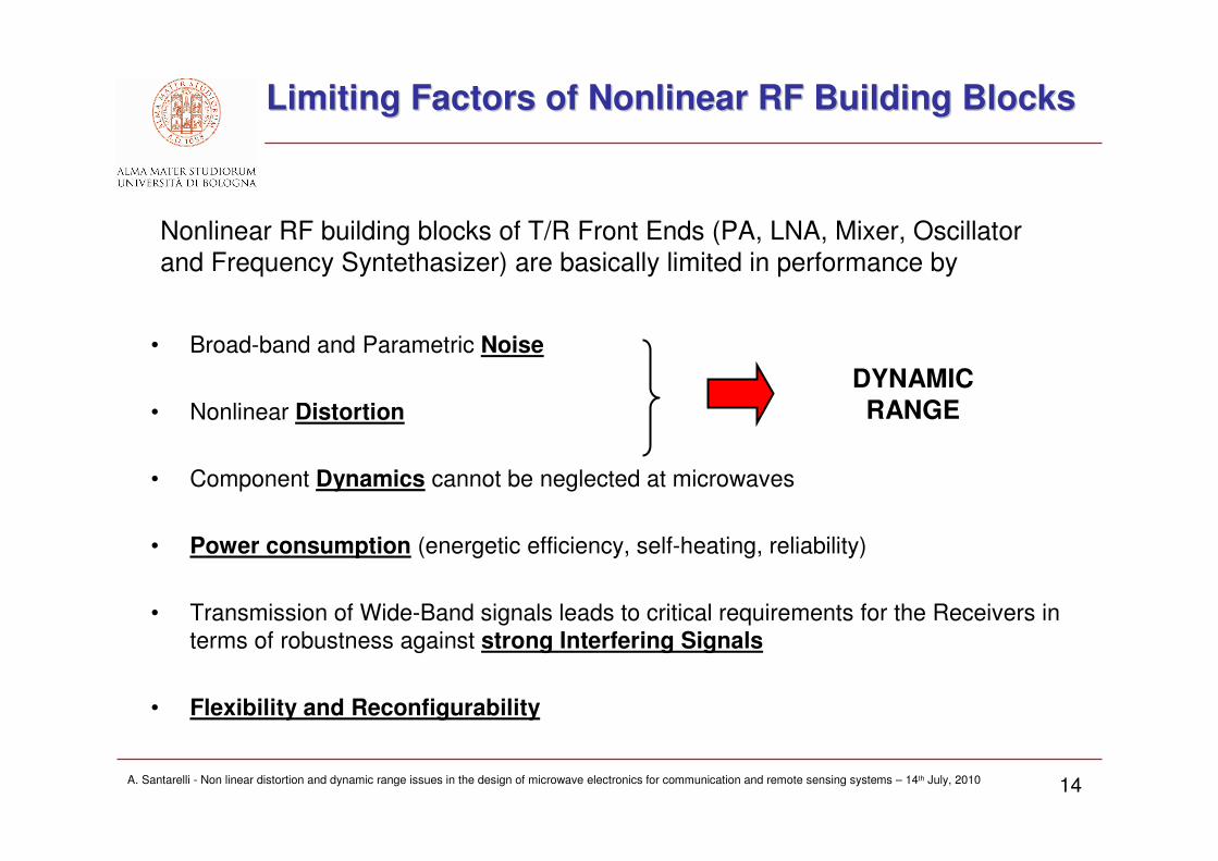
Limiting Factors of Nonlinear RF Building BlocksLimiting Factors of Nonlinear RF Building Blocks
• Broad-band and Parametric Noise
• Nonlinear Distortion
• Component Dynamics cannot be neglected at microwaves
• Power consumption (energetic efficiency, self-heating, reliability)
• Transmission of Wide-Band signals leads to critical requirements for the Receivers in
terms of robustness against strong Interfering Signals
• Flexibility and Reconfigurability
DYNAMICRANGE
Nonlinear RF building blocks of T/R Front Ends (PA, LNA, Mixer, Oscillator
and Frequency Syntethasizer) are basically limited in performance by
AFFILIATION LOGO
A. Santarelli - Non linear distortion and dynamic range issues in the design of microwave electronics for communication and remote sensing systems – 14th July, 2010 15
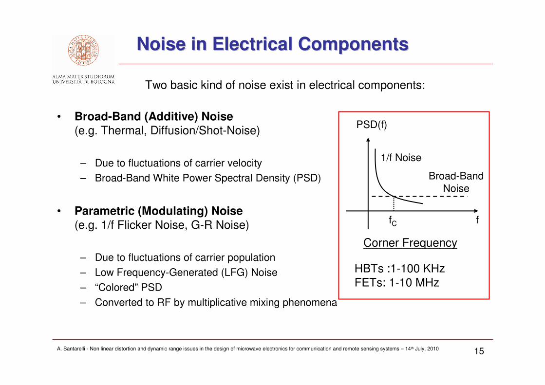
Noise in Electrical ComponentsNoise in Electrical Components
• Broad-Band (Additive) Noise(e.g. Thermal, Diffusion/Shot-Noise)
– Due to fluctuations of carrier velocity
– Broad-Band White Power Spectral Density (PSD)
• Parametric (Modulating) Noise(e.g. 1/f Flicker Noise, G-R Noise)
– Due to fluctuations of carrier population
– Low Frequency-Generated (LFG) Noise
– “Colored” PSD
– Converted to RF by multiplicative mixing phenomena
Broad-Band
Noise
1/f Noise
PSD(f)
ffC
Corner Frequency
HBTs :1-100 KHz
FETs: 1-10 MHz
Two basic kind of noise exist in electrical components:

AFFILIATION LOGO
A. Santarelli - Non linear distortion and dynamic range issues in the design of microwave electronics for communication and remote sensing systems – 14th July, 2010 16
Effects of Noise on T/R FrontEffects of Noise on T/R Front--End Performance End Performance
• Phase Noise of the locally generated oscillation: carrier generation with
inherent spurious “noisy” modulation
• Same problem both in the Transmitter and in the Receiver (Carrier
Recovery)
• No benefit from increasing signal power since phase noise side-band
amplitude also increases proportionally (non additive, but modulation noise)
Phase Noise
Broad-Band Noise
• Sensitivity (and dynamic range) reduction of the Low Noise Amplifier
• Noise Figure degradation due to strong adjacent interfering signals

AFFILIATION LOGO
A. Santarelli - Non linear distortion and dynamic range issues in the design of microwave electronics for communication and remote sensing systems – 14th July, 2010 17
At microwave frequencies (presence of reactive phenomena) the Power Amplifier is nonlinear with memory
Linear With Memory:
Nonlinear with Memory:
Nonlinear Memory-less:
0( ) ( ) ( )
MT
y t h x t dτ τ τ= −∫
1 1 1 10
2 1 2 1 2 1 2
3 1 2 3 1 2 3 1 2 3
( ) ( ) ( )
( , ) ( ) ( )
( , , ) ( ) ( ) ( )
MT
y t h x t d
h x t x t d d
h x t x t x t d d d
τ τ τ
τ τ τ τ τ τ
τ τ τ τ τ τ τ τ τ
= − +
+ − − +
+ − − − +
+
∫
∫∫
∫∫∫K
2 3
2 3( ) [ ( )] ( ) ( ) ( )y t f x t x t x t x tα α α1= = + + +K
VOLTERRA SERIES
Distortion in Nonlinear Components (focus on PA)Distortion in Nonlinear Components (focus on PA)
PAx(t) y(t)
Which description for the PA ?

AFFILIATION LOGO
A. Santarelli - Non linear distortion and dynamic range issues in the design of microwave electronics for communication and remote sensing systems – 14th July, 2010 18
A Simplified Description of A Simplified Description of PAsPAs
• Volterra kernels h1(τ1), h2(τ1, τ2), h3(τ1, τ2, τ3),… completely characterizethe amplifier nonlinear dynamic response
• Volterra series can be practically used only for weak non-linearity, since kernels measurement at microwave frequencies is difficult
• Modified Volterra Series descriptions exist. They are based on modified kernels and are more suited for practically dealing with weak and strong nonlinearities
However…
• For a simplified analysis of nonlinear distortion in power amplifiers a purely memory-less power amplifier is assumed in the following
Simplified Analysis
AFFILIATION LOGO
A. Santarelli - Non linear distortion and dynamic range issues in the design of microwave electronics for communication and remote sensing systems – 14th July, 2010 19
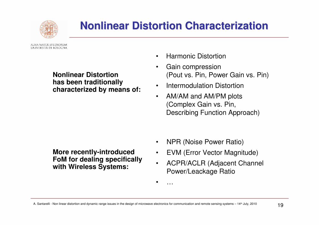
Nonlinear Distortion Characterization Nonlinear Distortion Characterization
• Harmonic Distortion
• Gain compression
(Pout vs. Pin, Power Gain vs. Pin)
• Intermodulation Distortion
• AM/AM and AM/PM plots
(Complex Gain vs. Pin,
Describing Function Approach)
Nonlinear Distortionhas been traditionallycharacterized by means of:
More recently-introducedFoM for dealing specificallywith Wireless Systems:
• NPR (Noise Power Ratio)
• EVM (Error Vector Magnitude)
• ACPR/ACLR (Adjacent Channel
Power/Leackage Ratio
• …

AFFILIATION LOGO
A. Santarelli - Non linear distortion and dynamic range issues in the design of microwave electronics for communication and remote sensing systems – 14th July, 2010 20
Harmonic Distortion (I) Harmonic Distortion (I)
SingleSingle--Tone Sinusoidal ExcitationTone Sinusoidal Excitation
0( ) cos( )x t X tω=
2 3
2 3( ) [ ( )] ( ) ( ) ( )y t f x t x t x t x tα α α1= = + + +K
ω
ω
|X(ω)|
|Y(ω)|
ω0
ω02ω03ω0 ….
PA Memory-less Model:
Input PA Excitation:
PA Output: ( )0
1
( ) [ ( )] cosAC DC k
k
y t f x t X X k tω∞
−=
= = + ⋅∑
Spectral re-growth at Harmonic (angular) Frequencies: kω0t
SPECTRUM
ANALYZER
SIN.
GEN.PA
x(t) y(t)
Scalar Measurement

AFFILIATION LOGO
A. Santarelli - Non linear distortion and dynamic range issues in the design of microwave electronics for communication and remote sensing systems – 14th July, 2010 21
Harmonic Distortion (II)Harmonic Distortion (II)
• Very simple
but scarcely meaningful
for microwave communications
• Out-of-band harmonics only
(output filtering possible)
• Results can be too optimistic
(selective output matching
networks = harmonic filtering)
• Non realistic input test signal
(constant amplitude carrier, no modulation, zero bandwidth)
Fig. from Ref. 3

AFFILIATION LOGO
A. Santarelli - Non linear distortion and dynamic range issues in the design of microwave electronics for communication and remote sensing systems – 14th July, 2010 22
Harmonic Distortion (III)Harmonic Distortion (III)
Typical PlotsTypical PlotsPout versus Pin
Transducer Power Gain vs. Pin
1dB
• 1dB (3dB) Compression Point
Pout1dB
Pin1dB

AFFILIATION LOGO
A. Santarelli - Non linear distortion and dynamic range issues in the design of microwave electronics for communication and remote sensing systems – 14th July, 2010 23
IntermodulationIntermodulation Distortion (I)Distortion (I)
TwoTwo--Tone Sinusoidal ExcitationTone Sinusoidal Excitation
1 2( ) cos( ) cos( )x t X t X tω ω= +
ω
PA Memory-less Model:
Input PA Excitation:
PA Output: ( ), 1 2
,
( ) [ ( )] cosAC DC m n
m n
y t f x t X X m t n tω ω−= = + ⋅ +∑
Spectral re-growth at Harmonic (angular) Frequencies: mω1t+nω2t
Scalar Measurement
SPECTRUM
ANALYZER
SIN.
GEN.
PA
x(t) y(t)
SIN.
GEN.
+
ω1
ω2
SMALL
TONE SPACING:
∆∆∆∆ω = ω2-ω1<< ω0
|X(ω)|
ω1 ω2
ω0
2 3
2 3( ) [ ( )] ( ) ( ) ( )y t f x t x t x t x tα α α1= = + + +K

AFFILIATION LOGO
A. Santarelli - Non linear distortion and dynamic range issues in the design of microwave electronics for communication and remote sensing systems – 14th July, 2010 24
1 1 2
3
3 1 2
( ) [cos( ) cos( )]
3[cos(( ) ) cos(( ) )]
4
out-of-band terms
in-band higher order (odd)
w t X t t
X t t
α ω ω
α ω ω ω ω
= ⋅ + +
+ ⋅ − ∆ + + ∆ +
+ +
+
In mild large-signal operation intermodulation distortion is mainly due to 3rd order non-linearity
3
3 3
1
6
d f
dxα =
IntermodulationIntermodulation Distortion (II)Distortion (II)
Fig. from Ref. 3
1 2 1
2 1 2
2
2
ω ω ω ω
ω ω ω ω
− = − ∆
− = + ∆

AFFILIATION LOGO
A. Santarelli - Non linear distortion and dynamic range issues in the design of microwave electronics for communication and remote sensing systems – 14th July, 2010 25
1
3
3IMD [dBc]PC
I P= =
ω1 ω2
∆∆∆∆ω ∆∆∆∆ω ∆∆∆∆ω
P1
P3 3rd-order IMD product
(in-band: co-channel distortion)
|X(ω)|
ω
|Y(ω)|
P5 5th-order IMD product
(out-band: adjacent channel distortion)
Channel
Bandwidth
Excitation
Tones
ω
IntermodulationIntermodulation Distortion (III)Distortion (III)
Carrier to Interference Ratio (CIR)

AFFILIATION LOGO
A. Santarelli - Non linear distortion and dynamic range issues in the design of microwave electronics for communication and remote sensing systems – 14th July, 2010 26
IntermodulationIntermodulation Distortion (IV)Distortion (IV)
• Co-channel and Adjacent Channel Distortion Evaluation
• Input test signal with non-zero bandwidth (amplitude and phase modulation)
• Quite simple measurement set-up
• Scalar Measurement
A closer look to the two-tone excitation…
ω0 = central carrier frequency
Ex(t) = complex modulation envelope
{ }0( ) Re ( )j t
xx t E t e
ω= ⋅
2 21 2( )
j t j t
xE t X e X e
ω ω∆ ∆−
= ⋅ + ⋅
EX(t) has variable amplitude and phase:
1 20 ( )x
E t X X≤ ≤ +
0 ( ) 2x
E t π≤ ∠ ≤
GOOD SIGNALFOR NONLINEAR TESTING

AFFILIATION LOGO
A. Santarelli - Non linear distortion and dynamic range issues in the design of microwave electronics for communication and remote sensing systems – 14th July, 2010 27
OUTPUT
IP3
INPUT
IP3
1
3
High-linearity
amplifier:
3
1
-30 -40 dBcP
P= ÷
3 1 33
2
P POIP
⋅ −=
ThirdThird--Order Intercept Point (IP3)Order Intercept Point (IP3)
Alternative way of expressing the PA distortion specification

AFFILIATION LOGO
A. Santarelli - Non linear distortion and dynamic range issues in the design of microwave electronics for communication and remote sensing systems – 14th July, 2010 28
Modulated input signal:
Output signal (neglecting out-of-band
harmonics, but including both co-channel
and adjacent channel interference):
Ex(t), Ey(t) are slowly time-varying when modulated signal bandwidth BW<<ω0
QUASI-STATIC AMPLIFIER DESCRIPTION
No memory on signal modulation envelopesbut PA complex response considered at ω0
G is a complex Describing Functiononly dependent on |Ex(t)| since PA is a
time-invariant non-linear system
{ }0( ) Re ( )j t
xx t E t e
ω= ⋅
{ }0( ) Re ( )j t
yy t E t e
ω= ⋅
0( ) , ( ) ( )
y x xE t G E t E tω= ⋅
Describing Function Model of Describing Function Model of PAsPAs

AFFILIATION LOGO
A. Santarelli - Non linear distortion and dynamic range issues in the design of microwave electronics for communication and remote sensing systems – 14th July, 2010 29
can be measured (vector voltmeter)
or computed (HB) under amplitude-swept
sinusoidal excitation
• G [ω0,|Ex(t)|] completely describes the nonlinear amplifier response to any
signal x(t) with relatively small bandwidth BW<< ω 0
• SCALAR GAIN COMPRESSION (1dB) NOT SUFFICIENT !
� no AM/PM conversion;
y
x
EG
E=
J GG G e
∠= ⋅
AM/AM
conversion
AM/PM
conversion
|Ex|
|G|
G∠
|Ex|
Complex
Describing
Function
AM/AM AM/AM -- AM/PM PA Behavioral ModelAM/PM PA Behavioral Model

AFFILIATION LOGO
A. Santarelli - Non linear distortion and dynamic range issues in the design of microwave electronics for communication and remote sensing systems – 14th July, 2010 30
Adjacent Channel Power Ratio (ACPR)Adjacent Channel Power Ratio (ACPR)
Quantifying PA performance in the final application
Adjacent ChannelPower Ratio (ACPR)
SPECTRUM
ANALYZER
(W)-CDMA
Modulated
Source
PA
x(t) y(t)
( )
( )
Bin
Bou
y
y
t
PDF f df
ACPRPDF f df
⋅
=⋅
∫
∫ Bout
Bin
Different definitions of Bin Bout
depending on the Ref. Std.
Fig. from Ref. 4
Fig. from Ref. 5

AFFILIATION LOGO
A. Santarelli - Non linear distortion and dynamic range issues in the design of microwave electronics for communication and remote sensing systems – 14th July, 2010 31
Noise Power Ratio (NPR)Noise Power Ratio (NPR)
• Used initially for characterizing multi-carrier
power amplifiers
• A broad-band Additive Gaussian White Noise
(AGWN) source is used to simulate the
presence of many carriers of random amplitude
and phase
• Band-pass Filtering approximately equal to the
Channel Bandwidth
• Equivalent to: (C+I)/I
SPECTRUM
ANALYZER
AGWN
Source PAx(t) y(t)
Notch
FilterBand-
pass
Filter
Fig. from Ref. 6

AFFILIATION LOGO
A. Santarelli - Non linear distortion and dynamic range issues in the design of microwave electronics for communication and remote sensing systems – 14th July, 2010 32
Error Vector Magnitude (EVM)Error Vector Magnitude (EVM)
Vector
Signal
Analyzer
Digitally
Modulated
Source
PA
x(t) y(t)
• PA Specifications often given in terms of peak and rms value of the EVM
Figs. from Ref. 7

AFFILIATION LOGO
A. Santarelli - Non linear distortion and dynamic range issues in the design of microwave electronics for communication and remote sensing systems – 14th July, 2010 33
Specs. of various Wireless Systems (example)Specs. of various Wireless Systems (example)
Fig. from Ref. 8
ACPR

AFFILIATION LOGO
A. Santarelli - Non linear distortion and dynamic range issues in the design of microwave electronics for communication and remote sensing systems – 14th July, 2010 34
Energetic EfficiencyEnergetic Efficiency
PAx(t) y(t)
RF
outPRF
inP
DC
inP
Power Added Efficiency
RF RF
out in
DC RF
in in
P PPAE
P P
−=
+
Energetic Efficiency
RF
out
DC RF
in in
P
P Pη =
+
In the presence of an modulated signal, efficiency becomes a function of the
instantaneous signal envelope amplitude
Average Energetic Efficiency
RF
out
DC RF
in in
P
P Pη =
+
where, for instance: ( )RF
out y y yP P E E dE= ⋅∫p(E) Probability Density Function of the Envelope Amplitude
Fig. from Ref. 8

AFFILIATION LOGO
A. Santarelli - Non linear distortion and dynamic range issues in the design of microwave electronics for communication and remote sensing systems – 14th July, 2010 35
Thermal Aspects (PA SelfThermal Aspects (PA Self--Heating)Heating)
Power dissipated into the device:(time-dependent quantity due to the inst.
variations of the Env. Amplitude)
• High-Efficiency is needed for limiting the Internal Device Temperature
• Peak and Average Internal Device Temperature must be kept under tolerable
limits for reliability
• Proper design of the assembly structures for optimal heat extraction (package)
11DC RF RF RF
D in in out outP P P P P
η
= + − = ⋅ −
Internal Device Temperature:
(thought as spatially averaged
along the FET channel)Channel-to-Back-Side
Thermal Resistance
[W/°C]
B DT T R Pϑ= + ⋅
Wafer Back-Side
Temperature

AFFILIATION LOGO
A. Santarelli - Non linear distortion and dynamic range issues in the design of microwave electronics for communication and remote sensing systems – 14th July, 2010 36
Linearity vs. Efficiency TradeLinearity vs. Efficiency Trade--offoff
• In many power amplifier (e.g. class-A/AB) the maximum efficiency is obtained
for peak output power corresponding to a maximum of tolerable distortion
• Whenever the instantaneous input signal envelope amplitude corresponds to
input power lower than PEP the efficiency dramatically drops
• Constraints on PA distortion often lead to choose: PEP << Pin1dB (BACK-OFF)
[dBm]PEP
RF Output Power
[dBm]
RF
inP
RF
outP
ˆ RF
outP
[dBm]
DC input Power
[W]
RF
inP
DC
inP
PEP
η Efficiency
[%]
[dBm]
RF
inP
η̂
PEP
(Peak Envelope Power – PEP) Figs. from Ref. 8

AFFILIATION LOGO
A. Santarelli - Non linear distortion and dynamic range issues in the design of microwave electronics for communication and remote sensing systems – 14th July, 2010 37
Peak to Average Ratio (PAR)Peak to Average Ratio (PAR)
• High-spectral-efficiency modulation
schemes are characterized by large PARs
(or crest factor)
• The same happens when a large number of independently modulated sub-
carriers are added to form the signal to be transmitted (such as with OFDM)
• PA average energetic efficiency
may become extremely low
in the presence of large PARs
combined with power back-off
• Dedicated PA solutions needed
(e.g. Doherty Amplifier)
PAR (typ.) [dB]Mod. (examples)
12OFDM
10.6W-CDMA (DL carrier)
7.764-QAM
3.5-4QPSK
( )
( )
v peak
v rms
tPAR
t=
E
E
&
&
vE& Complex envelope
of the modulated signal
AFFILIATION LOGO
A. Santarelli - Non linear distortion and dynamic range issues in the design of microwave electronics for communication and remote sensing systems – 14th July, 2010 38
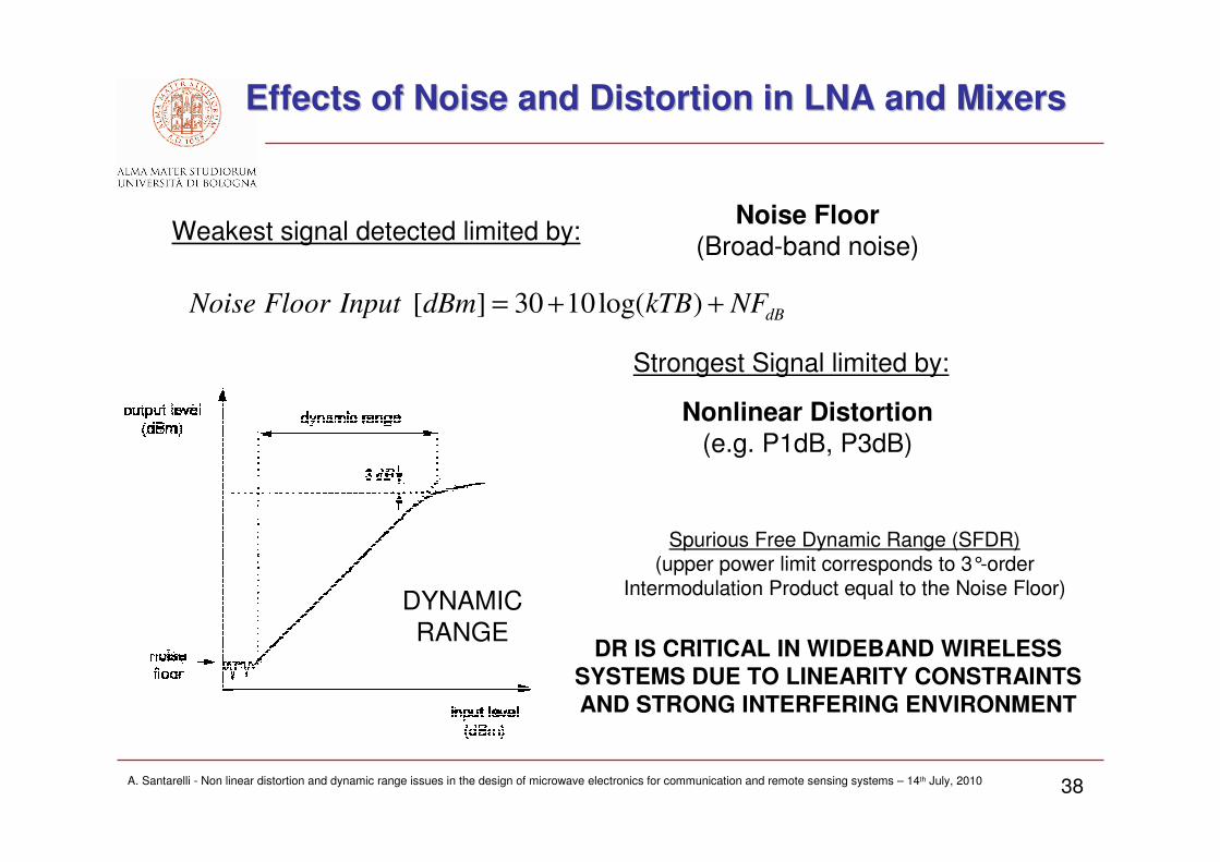
Effects of Noise and Distortion in LNA and MixersEffects of Noise and Distortion in LNA and Mixers
Noise Floor(Broad-band noise)
Strongest Signal limited by:
Weakest signal detected limited by:
Nonlinear Distortion(e.g. P1dB, P3dB)
DYNAMIC
RANGE
[ ] 30 10log( )dB
Noise Floor Input dBm kTB NF= + +
Spurious Free Dynamic Range (SFDR)(upper power limit corresponds to 3°-order
Intermodulation Product equal to the Noise Floor)
DR IS CRITICAL IN WIDEBAND WIRELESS SYSTEMS DUE TO LINEARITY CONSTRAINTS AND STRONG INTERFERING ENVIRONMENT

AFFILIATION LOGO
A. Santarelli - Non linear distortion and dynamic range issues in the design of microwave electronics for communication and remote sensing systems – 14th July, 2010 39
The Doherty Power Amplifier (I)The Doherty Power Amplifier (I)
• Two PAs combined
– Carrier PA (class-B)
– Peaking PA (class-C)
• Only Carrier PA is working forsmall input signal envelopeamplitude (e.g. Pin < α ⋅ PEPwith 0.25<α<0.5)
• Max. efficiency of the Carrier PA isachieved at Pin = α ⋅ PEP (ideally 78.5%)
• Both PAs contribute output power for Pin > α ⋅ PEP
• Equivalent load impedances vary with increasing envelope amplitude (ZLCarrier ↓, ZLPeaking ↑) implementing a sort of “active load-pulling” mechanism
• Both PAs deliver 50% of output power at PEP
Fig. from Ref. 8

AFFILIATION LOGO
A. Santarelli - Non linear distortion and dynamic range issues in the design of microwave electronics for communication and remote sensing systems – 14th July, 2010 40
The Doherty Power Amplifier (II)The Doherty Power Amplifier (II)
• Average efficiencies nearly doubledat equal ACPR
• Lower α are chosen for high-PAR signals
• Limitations exist with UWB signals due tofreq. selective matching networks and transmission lines
S-Band TX50W – Si-LDMOS
IS-95 CDMA
Figs. from Ref. 8
AFFILIATION LOGO
A. Santarelli - Non linear distortion and dynamic range issues in the design of microwave electronics for communication and remote sensing systems – 14th July, 2010 41
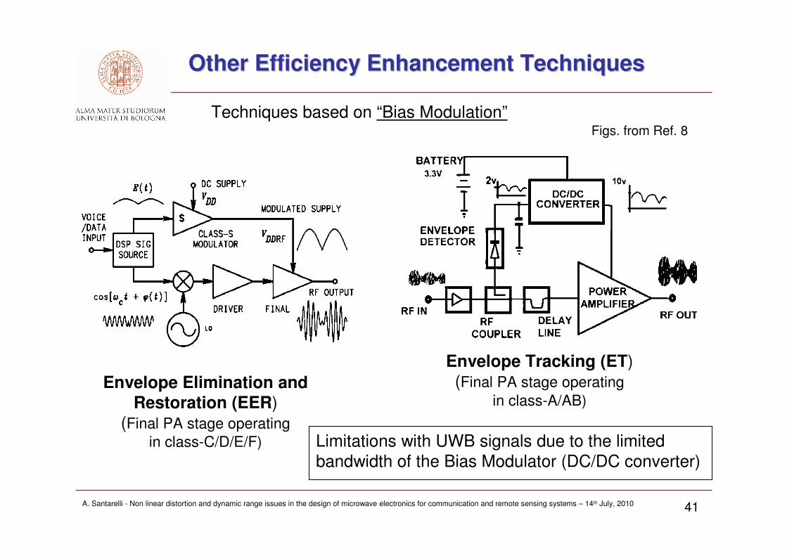
Other Efficiency Enhancement TechniquesOther Efficiency Enhancement Techniques
Limitations with UWB signals due to the limited
bandwidth of the Bias Modulator (DC/DC converter)
Envelope Elimination and Restoration (EER)
(Final PA stage operating
in class-C/D/E/F)
Techniques based on “Bias Modulation”
Envelope Tracking (ET)
(Final PA stage operating
in class-A/AB)
Figs. from Ref. 8

AFFILIATION LOGO
A. Santarelli - Non linear distortion and dynamic range issues in the design of microwave electronics for communication and remote sensing systems – 14th July, 2010 42
PA Linearization TechniquesPA Linearization Techniques
• FeedBack
• FeedForward
• Predistortion
Three main families of PA Linearization Techniques:
Example: (DIGITAL) PREDISTORTION
Red: Unlin. PA
Blue: Linearized PA
Figs. from Ref. 8, 9

AFFILIATION LOGO
A. Santarelli - Non linear distortion and dynamic range issues in the design of microwave electronics for communication and remote sensing systems – 14th July, 2010 43
• Conflicting requirements on output power, efficiency and high linearity
• Search for optimal values of source/load impedances, bias conditions, bias networks, non-linearity compensating structures, etc
• Device technology suitably chosen according to frequency, output power,…
• Source/Load-pull device characterization(IMD, output power, power-added-efficiency plots)
• Numerical simulation with suitable non-linear transistor models and CAD tools (Harmonic Balance, Transient Simulation, Envelope Simulation)
DESIGN TOOLS
PA DesignPA Design

AFFILIATION LOGO
A. Santarelli - Non linear distortion and dynamic range issues in the design of microwave electronics for communication and remote sensing systems – 14th July, 2010 44
-1
-0.5
0
0.5
1
-1
-0.5
0
0.5
10
20
40
60
80
40
40
50
50
-1
-0.5
0
0.5
1
-1
-0.5
0
0.5
10
20
40
60
80
40
40
50
50
Output Power (1st Harmonic)
Source/Load Pull PA CharacterizationSource/Load Pull PA Characterization
Plots of main FoM versus input/output reflection coefficients (impedances)

AFFILIATION LOGO
A. Santarelli - Non linear distortion and dynamic range issues in the design of microwave electronics for communication and remote sensing systems – 14th July, 2010 45
Nonlinear Transistor Models Nonlinear Transistor Models
Physics-based models: derived by physical principles applied to the
device structure
• Direct link between technological process parameters (materials,
geometry, doping profile,…) and electrical response
• More suitable for device design/analysis
Empirical Compact Models: measurements based
e.g. Equivalent Circuits use of lumped circuital elements to describe
measured characteristics
• Numerically efficient
• Widely used for MMIC and HMIC design

AFFILIATION LOGO
A. Santarelli - Non linear distortion and dynamic range issues in the design of microwave electronics for communication and remote sensing systems – 14th July, 2010 46
IC Technologies for T/R FrontIC Technologies for T/R Front--EndsEnds
• Base-Band Processing:CMOS
• RF Front-Ends in Handset and Portable Devices (Pout < 1W):SiGe HBT (BiCMOS Integrated Circuits), CMOS, BJT
• RF Front-Ends in Base-Stations (Pout ~ 10-100 W):Si-LDMOS, GaN-HEMT
Wireless
Back-Haul, Satellite Links, SpaceRadio-Astronomy, Radars (GHz<f<THz)
• GaAs-PHEMT, GaN-HEMT, GaAs-HBT, InP-PHEMT
Transistors may be available for:
Mixed Analog/Digital Integrated Circuits, MMIC Design,
or in Package or Die for Hybrid Solutions

AFFILIATION LOGO
A. Santarelli - Non linear distortion and dynamic range issues in the design of microwave electronics for communication and remote sensing systems – 14th July, 2010 47
PAsPAs for Handsets (Technology Overview for Handsets (Technology Overview -- Dec Dec ‘‘09)09)
Fig. from Ref. 10

AFFILIATION LOGO
A. Santarelli - Non linear distortion and dynamic range issues in the design of microwave electronics for communication and remote sensing systems – 14th July, 2010 48
SiGeSiGe HeterojunctionHeterojunction Bipolar Transistor (HBT)Bipolar Transistor (HBT)
• Similar to well-known BJT, but the Base region is implemented by SiGe instead of Si by creating hetero-junctions (H-J).
• Due to the specific properties of H-J, electron injection efficiency is strongly improved even in the presence of a heavily doped Base
• Very small parasitic effects(and Base resistance) obtained alsothanks to the high Base doping
• Extremely good Transition Frequency (frequency at unity current gain with
short-circuited output)
• Integration with Standard CMOSprocesses (BiCMOS)
Fig. from Ref. 11

AFFILIATION LOGO
A. Santarelli - Non linear distortion and dynamic range issues in the design of microwave electronics for communication and remote sensing systems – 14th July, 2010 49
BiCMOSBiCMOS (Si(Si--CMOS+SiGeCMOS+SiGe HBT) TechnologyHBT) Technology
Fig. from Ref. 12 (NEC)0.18-um RF SiGe BiCMOS
• Analog, RF and Digital Circuit Integrated into a single IC Process
• Most suited technology for the Software Defined Radio
• SiGe-HBT offers very low-noise (both 1/f and broad-band)
• Highly reliable

AFFILIATION LOGO
A. Santarelli - Non linear distortion and dynamic range issues in the design of microwave electronics for communication and remote sensing systems – 14th July, 2010 50
High High PowerPower MOSFETsMOSFETs –– SiSi--LDMOSLDMOS
• Wide low-doped Drift Drain region for high Break-Down Voltage
• Wide channel widths (distributed structures)for High Drain Currents
• Output Power: tens/hundreds of Watt

AFFILIATION LOGO
A. Santarelli - Non linear distortion and dynamic range issues in the design of microwave electronics for communication and remote sensing systems – 14th July, 2010 51
High Electron Mobility Transistors (HEMT)High Electron Mobility Transistors (HEMT)
• Hetero-Junction (H-J) between AlGaN and GaN layers
• N-Channel confined in a very shallow, almost bi-dimensional region into the intrinsic-GaN
• Extremely high mobility of carriers in the intrinsic GaN
• Devices obtained with high Break-down voltages (~100V), high power densities (5W/mm)
• SiC or Sapphire substrates
• Quite expensive but extremely promising technology Fig. from Ref. 13

AFFILIATION LOGO
A. Santarelli - Non linear distortion and dynamic range issues in the design of microwave electronics for communication and remote sensing systems – 14th July, 2010 52
A A GaNGaN Foundry Example: Foundry Example: TriQuintTriQuint
Fig. from Ref. 14
AFFILIATION LOGO
A. Santarelli - Non linear distortion and dynamic range issues in the design of microwave electronics for communication and remote sensing systems – 14th July, 2010 53
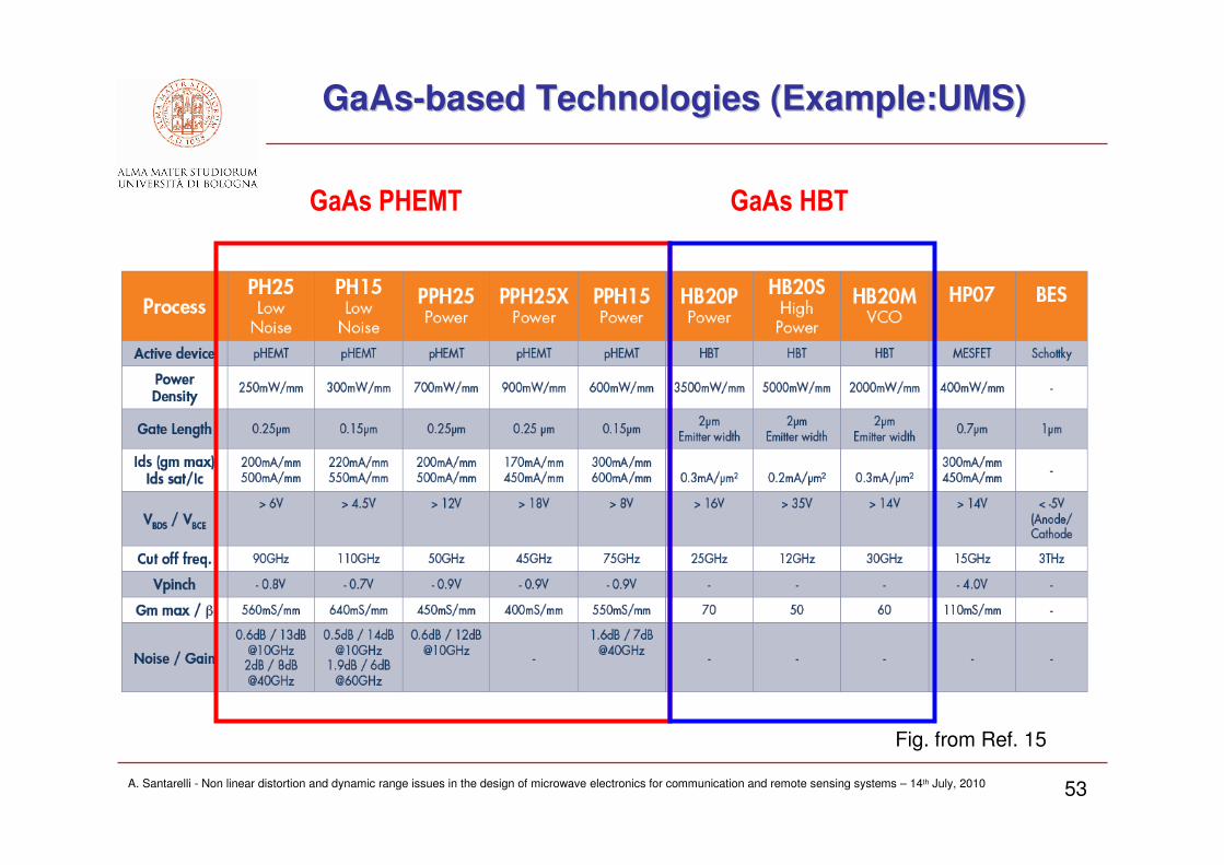
GaAs PHEMT GaAs HBT
GaAsGaAs--basedbased Technologies (Technologies (ExampleExample:UMS):UMS)
Fig. from Ref. 15

AFFILIATION LOGO
A. Santarelli - Non linear distortion and dynamic range issues in the design of microwave electronics for communication and remote sensing systems – 14th July, 2010 54
GaAsGaAs--basedbased Technologies (Technologies (ExampleExample: UMS): UMS)
Fig. from Ref. 15

AFFILIATION LOGO
A. Santarelli - Non linear distortion and dynamic range issues in the design of microwave electronics for communication and remote sensing systems – 14th July, 2010 55
Figure ReferencesFigure References
1. G. Fisher, “Next-Generation Base Station Radio Frequency Architecture”, Wiley Bell Labs Technical Journal, Vol12 , N. 2, Aug 2007
2. B. Razavi, “RF microelectronics “, Prentice Hall, 1997
3. P. Wambacq, W. Sansen, “Distortion Analysis of Analog Integrated Circuits”, Kluver Academic Press, 1998
4. Agilent AN 1307,” Testing CDMA Base Station Amplifiers”, Application Note, 2000
5. “Adjacent Channel Power Ratio (ACPR)”, Application Note, Anritsu, 20016. K. M. Gharaibeh, K. G. Gard, M. B. Steer, “The Applicability of Noise Power Ratio (NPR) in Real Communication
Signals”, ARFTG Conference, 2006 67th , vol., no., pp.251-253, 16-16 June 2006
7. Agilent PN 89400-14, “Using Error Vector Magnitude Measurements to Analyze and Troubleshoot Vector-Modulated Signals”, Product Note, 2000
8. F. H. Raab, P. Asbeck, S. Cripps, P. B. Kenington, Z. B. Popovic, N. Pothecary, J. F. Sevic and N. O. Sokal, “RF and Microwave Power Amplifier and Transmitter Technologies. Part I-II-III-IV”, High Frequency Electronics, Summit Technical Media, LLC, May 2003
9. W.-J. Kim, S. P. Stapleton, J. H. Kim, C. Edelman, “Digital Predistortion Linearizes Wireless Power Amplifiers”, IEEE Microwave Magazine, Sep 2005.
10. J. Choi, D. Kang, D. Kim, J. Park, B. Jin, and B. Kim, “Power Amplifiers and Transmitters for Next Generation Mobile Handsets”, Journ. Of Semiconductor Technology And Science, Vol.9, N.4, Dec 2009.
11. J.-S. Rieh , "A brief overview of modern high-speed SiGe HBTs," 8th Int- Conf. on Solid-State and Int. Circ. Tech., ICSICT '06, pp.170-173, Oct. 2006.
12. F. Sato, T. Hashimoto, H. Fujii, H. Yoshida, H. Suzuki, T. Yamazaki, “A 0.18-um RF SiGe BiCMOS Technology With Collector-Epi-Free Double-Poly Self-Aligned HBTs”, IEEE Trans. On Elect. Dev., Vol.50, N.3, Mar. 2003.
13. S. Zhong, T. Chen, C. Ren, G. Jiao, C. Chen, K. Shao, N. Yang, “AlGaN/GaN HEMT with over 110 W Output Power for X-Band”, Proc. of the 3rd European Micr. Int. Circ. Conf. (EuMIC’08), Oct 2008.
14. http://www.triquint.com
15. http://www.ums-gaas.com