Embed Size (px)
Citation preview

Non-Interpretive
12-Lead ECG Monitoring
9650-0218-01 Rev. B
This issue date or revision level for this operation guide is shown on the front cover. ZOLL and M Series are trademarks of ZOLL Medical Corporation. © 2002 by ZOLL Medical Corporation. All rights reserved
9650-0218-01 Non-Interpretive 12-lead - 1 Rev. B
NON–INTERPRETIVE 12-LEAD ECG
MONITORING
ECG leads are a defibrillation protected Type CF patient connection.
General Information
Product Description
ZOLL M Series with non-interpretive 12-lead option provides simultaneous 12-lead ECG acquisition, storage, display, and transmission.
Intended Use
The ZOLL M Series with non-interpretive 12-lead ECG monitoring is intended for the recording and transmission of 12-lead ECG signals acquired from adult and pediatric patients in the supine, resting position.
Indications
The 12-lead ECG is useful in the diagnosis and treatment of patients with acute myocardial infarction (AMI). 12-lead ECG is also useful in the interpretation and documentation of other transient cardiac arrhythmias that may occur. When used in the prehospital setting, the 12-lead ECG can be of assistance in diagnosis and treatment decisions once the patient has arrived in the hospital emergency department.
How to Use This Manual This manual provides instructions for using the ZOLL M Series with non-interpretive 12-lead option. It does not contain information on how to read or interpret electrocardiograms (ECGs ). It covers the following:
• Warnings
• Electrode Placement
• 12-Lead Acquisition
• 12-Lead ECG Data Transmission
• 12-Lead Reports
• Daily Operational Verification
• Troubleshooting
OPTION INSERT
9650-0218-01 Non-Interpretive 12-lead - 2
WARNINGS
• Before use, carefully read the M Series Operator’s Guide and these operating instructions.
• The M Series with non-interpretive 12-lead ECG is designed to acquire ECG data from resting, supine patients. Use of the device to acquire ECG signals from moving or shaking patients may produce erroneous 12-lead data. Always ensure that the patient is kept motionless during 12-lead ECG signal acquisition.
• Excessive body hair or wet, sweaty skin may interfere with electrode adhesion. Remove the hair and/or moisture from the area where the electrode is to be attached.
• Using previously opened or out of date electrodes may degrade the ECG signal quality. ECG electrodes should be removed from their sealed package immediately prior to use.
• Monitoring electrodes may become polarized during defibrillator discharge, causing the ECG waveform to briefly go off screen. ZOLL Medical Corporation recommends the use of high quality silver/ silver chloride (Ag/AgCl) electrodes to minimize this effect, and circuitry in the instrument will return the trace to the monitor display within a few seconds.
• Wait 15 seconds after defibrillator discharge before attempting a 12-lead acquisition. Electrode polarization subsequent to defibrillator discharge may result in excessive noise on the 12-lead ECG printout.
• Cover the patient cable's V-lead connector with the plastic cap supplied when the V-leads are not in use. Failure to do so may result in a shock hazard during defibrillation attempts.
• To assure protection against the effects of defibrillator discharge use only 12-lead cables supplied by ZOLL Medical Corporation.
• To avoid a shock hazard and interference from nearby electrical equipment keep electrodes and patient cables away from grounded metal and other electrical equipment.
• Do NOT sterilize the M Series unit or any of its accessories except internal handles or as directed.
• Check the operation and integrity of your M Series and 12-lead cable regularly by performing the Daily Operational Verification Test.
• Grounding reliability can ONLY be achieved when the equipment is connected to an equivalent receptacle marked “HOSPITAL ONLY” or “HOSPITAL GRADE”.
• The frequency response of the monitor screen is intended only for basic ECG rhythm identification; it does not provide the resolution required for diagnostic and ST segment interpretation. Use the strip chart recorder for th is purpose.
• Implanted pacemakers may cause the heart rate meter to count the pacemaker rate during incidents of cardiac arrest or other arrhythmias. Pacemaker patients should be carefully observed. Check the patient's pulse; do not rely solely on heart rate meters. Dedicated pacemaker detection circuitry may not detect all implanted pacemaker spikes. Patient history and physical exam are important in determining the presence of an implanted pacemaker.

Non-Interpretive 12-lead
9650-0218-01 Non-Interpretive 12-lead - 3
Electrode Placement
Location AHA Labels IEC Labels
Right Arm RA (white) R (red)
Left Arm LA (black) L (yellow)
Right Leg RL (green) N (black)
Left Leg LL (red) F (green)
Chest V1 C1
Chest V2 C2
Chest V3 C3
Chest V4 C4
Chest V5 C5
Chest V6 C6
Place electrodes on the patient. All electrodes must be connected. Proper skin preparation and use of proper electrodes are very important for a good signal quality. If necessary prepare the patient’s skin for electrode application by ;
• Shaving or clipping excess hair at electrode site . Avoid placing electrodes over tendons and major muscle masses.
• Cleaning oily skin with an alcohol pad.
• Briskly rubbing site to dry.
When acquiring 12-lead ECG from quiet supine patients, ZOLL recommends placing the limb electrodes anywhere along the ankles and wrists. When it is difficult for the patient to remain motionless due to shivering, muscle tremors, or transport vehicle movement, better results are often obtained if limb electrodes are placed on the patient’s thorax. (Refer to the two diagrams below for limb electrode placement).
RA/R LA/L
RL/N LL/F
Place the precordial electrodes across the chest in the following locations;
V1 : Fourth intercostal space, at the right sternal margin. V2 : Fourth intercostal space, at the left sternal margin.
V3 : Fifth rib, between leads V2 and V4.
V4 : Fifth intercostal space, on the left midclavicular line.
V5 : Left anterior axillary line, at the horizontal level of V4.
V6 : Left midaxillary line, at the same horizontal level as V4 and V5.
Locating the V1 position (fourth intercostal space) is critically important because it is the reference point for locating the placement of the remaining V leads. To locate the V1 position:
1. Place your finger on top of the jugular notch (see figure below).
2. Move your finger slowly downward about 1.5 inches (3.8 centimeters) until you feel a slight horizontal ridge or elevation. This is the "Angle of Louis" where the manubrium joins the body of the sternum.
3. Locate the second intercostal space on the right side, lateral to and just below the Angle of Louis.
4. Move your finger down two more intercostal spaces to the fourth intercostal space which is the V1 position.
Note: When placing electrodes on female patients, always place leads V3-V6 under the breast rather than on the breast.
Angle of Louis Jugular notch
OPTION INSERT
9650-0218-01 Non-Interpretive 12-lead - 4
12-LEAD ACQUISITION • Attach the electrodes to the patient (Refer to the
“Electrode Placement” Section).
• Attach the 12-lead cable lead wires to the electrodes on the patient.
• Attach the V-lead cable to the 12-lead ECG cable. (When V-leads are not in use, ensure the V-leads protective cap is plugged into the V-lead connector).
• Attach the 12-lead cable to the rear of the M Series product.
• Cable Dress: Arrange the 12-lead cable such that it is neat and not dangling or looped. Assure that the cable is not pulling on individual electrodes.
• Turn the selector switch to MONITOR mode.
• If “PADS” or “PADDLES” are selected, select Lead I. (Leads must be selected to obtain a 12-lead printout).
• To print a 12-lead report ONLY, press and hold the RECORDER button for 3 seconds. The unit will begin printout of the 12-lead report.
• To transmit the 12-lead report to a fax machine, see the “12-Lead ECG Data Transmission” section below.
• The default bandwidth for 12-lead ECG data is 0.05 to 150 Hz. An alternate bandwidth of 0.05 to 40 Hz is selectable by the user if excessive muscle or other artifact is present during 12-lead recording. Refer to the “Filter Settings” section for instructions on how to select this configuration.
PHYSIOLOGICAL MONITORING
When the M Series device is turned to MONITOR mode, the physiological monitoring menu will be displayed with the following softkeys: Param, Wave2, ID#, Alarms and 12 Lead.
If the user enters 12-lead Monitoring with two (2) waveforms displayed, the waveforms will remain displayed on the screen during 12-lead Monitoring. Pressing the Wave 2 softkey removes the second waveform prior to entering 12-lead Monitor mode.
For AED units the 12 Lead soft key is the third from the left.
12 Lead Softkey
When the 12 Lead softkey is pressed the following screen will be displayed.
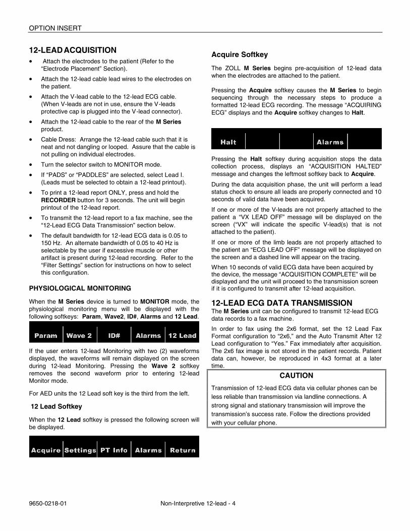
Acquire Softkey
The ZOLL M Series begins pre-acquisition of 12-lead data when the electrodes are attached to the patient.
Pressing the Acquire softkey causes the M Series to begin sequencing through the necessary steps to produce a formatted 12-lead ECG recording. The message “ACQUIRING ECG” displays and the Acquire softkey changes to Halt.
Pressing the Halt softkey during acquisition stops the data collection process, displays an “ACQUISITION HALTED” message and changes the leftmost softkey back to Acquire.
During the data acquisition phase, the unit will perform a lead status check to ensure all leads are properly connected and 10 seconds of valid data have been acquired.
If one or more of the V-leads are not properly attached to the patient a “VX LEAD OFF” message will be displayed on the screen (“VX” will indicate the specific V-lead(s) that is not attached to the patient).
If one or more of the limb leads are not properly attached to the patient an “ECG LEAD OFF” message will be displayed on the screen and a dashed line will appear on the tracing.
When 10 seconds of valid ECG data have been acquired by the device, the message “ACQUISITION COMPLETE” will be displayed and the unit will proceed to the transmission screen if it is configured to transmit after 12-lead acquisition. 12-LEAD ECG DATA TRANSMISSION The M Series unit can be configured to transmit 12-lead ECG data records to a fax machine.
In order to fax using the 2x6 format, set the 12 Lead Fax Format configuration to “2x6,” and the Auto Transmit After 12 Lead configuration to “Yes.” Fax immediately after acquisition. The 2x6 fax image is not stored in the patient records. Patient data can, however, be reproduced in 4x3 format at a later time.
CAUTION
Transmission of 12-lead ECG data via cellular phones can be less reliable than transmission via landline connections. A strong signal and stationary transmission will improve the transmission’s success rate. Follow the directions provided with your cellular phone.
Non-Interpretive 12-lead
9650-0218-01 Non-Interpretive 12-lead - 5
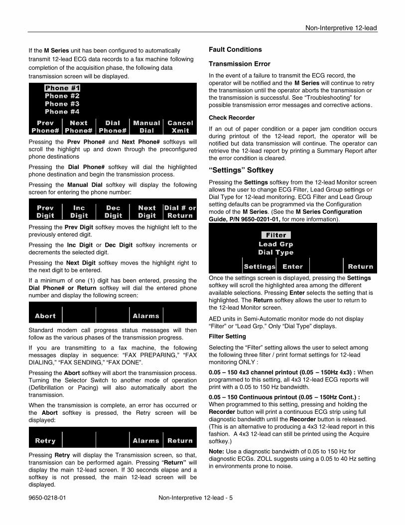
If the M Series unit has been configured to automatically transmit 12-lead ECG data records to a fax machine following completion of the acquisition phase, the following data transmission screen will be displayed.
Pressing the Prev Phone# and Next Phone# softkeys will scroll the highlight up and down through the preconfigured phone destinations
Pressing the Dial Phone# softkey will dial the highlighted phone destination and begin the transmission process.
Pressing the Manual Dial softkey will display the following screen for entering the phone number:
Pressing the Prev Digit softkey moves the highlight left to the previously entered digit.
Pressing the Inc Digit or Dec Digit softkey increments or decrements the selected digit.
Pressing the Next Digit softkey moves the highlight right to the next digit to be entered.
If a minimum of one (1) digit has been entered, pressing the Dial Phone# or Return softkey will dial the entered phone number and display the following screen:
Standard modem call progress status messages will then follow as the various phases of the transmission progress.
If you are transmitting to a fax machine, the following messages display in sequence: “FAX PREPARING,” “FAX DIALING,” “FAX SENDING,” “FAX DONE”.
Pressing the Abort softkey will abort the transmission process. Turning the Selector Switch to another mode of operation (Defibrillation or Pacing) will also automatically abort the transmission.
When the transmission is complete, an error has occurred or the Abort softkey is pressed, the Retry screen will be displayed:
Pressing Retry will display the Transmission screen, so that, transmission can be performed again. Pressing “Return” will display the main 12-lead screen. If 30 seconds elapse and a softkey is not pressed, the main 12-lead screen will be displayed.
Fault Conditions
Transmission Error
In the event of a failure to transmit the ECG record, the operator will be notified and the M Series will continue to retry the transmission until the operator aborts the transmission or the transmission is successful. See “Troubleshooting” for possible transmission error messages and corrective actions.
Check Recorder
If an out of paper condition or a paper jam condition occurs during printout of the 12-lead report, the operator will be notified but data transmission will continue. The operator can retrieve the 12-lead report by printing a Summary Report after the error condition is cleared.
“Settings” Softkey
Pressing the Settings softkey from the 12-lead Monitor screen allows the user to change ECG Filter, Lead Group settings or Dial Type for 12-lead monitoring. ECG Filter and Lead Group setting defaults can be programmed via the Configuration mode of the M Series. (See the M Series Configuration Guide, P/N 9650-0201-01, for more information).
Once the settings screen is displayed, pressing the Settings softkey will scroll the highlighted area among the different available selections. Pressing Enter selects the setting that is highlighted. The Return softkey allows the user to return to the 12-lead Monitor screen.
AED units in Semi-Automatic monitor mode do not display “Filter” or “Lead Grp.” Only “Dial Type” displays.
Filter Setting
Selecting the “Filter” setting allows the user to select among the following three filter / print format settings for 12-lead monitoring ONLY :
0.05 – 150 4x3 channel printout (0.05 – 150Hz 4x3) : When programmed to this setting, all 4x3 12-lead ECG reports will print with a 0.05 to 150 Hz bandwidth.
0.05 – 150 Continuous printout (0.05 – 150Hz Cont.) : When programmed to this setting, pressing and holding the Recorder button will print a continuous ECG strip using full diagnostic bandwidth until the Recorder button is released. (This is an alternative to producing a 4x3 12-lead report in this fashion. A 4x3 12-lead can still be printed using the Acquire softkey.)
Note: Use a diagnostic bandwidth of 0.05 to 150 Hz for diagnostic ECGs. ZOLL suggests using a 0.05 to 40 Hz setting in environments prone to noise.
OPTION INSERT
9650-0218-01 Non-Interpretive 12-lead - 6
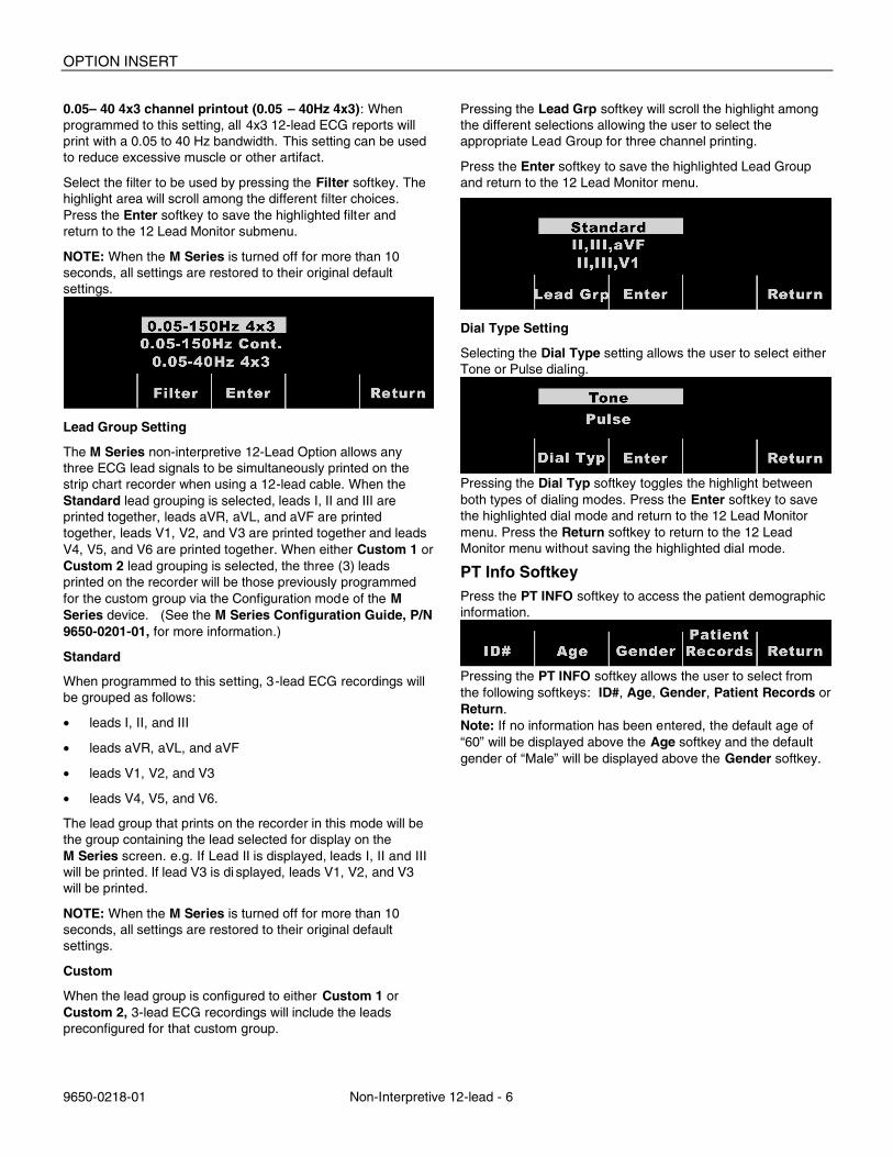
0.05– 40 4x3 channel printout (0.05 – 40Hz 4x3): When programmed to this setting, all 4x3 12-lead ECG reports will print with a 0.05 to 40 Hz bandwidth. This setting can be used to reduce excessive muscle or other artifact.
Select the filter to be used by pressing the Filter softkey. The highlight area will scroll among the different filter choices. Press the Enter softkey to save the highlighted filter and return to the 12 Lead Monitor submenu.
NOTE: When the M Series is turned off for more than 10 seconds, all settings are restored to their original default settings.
Lead Group Setting
The M Series non-interpretive 12-Lead Option allows any three ECG lead signals to be simultaneously printed on the strip chart recorder when using a 12-lead cable. When the Standard lead grouping is selected, leads I, II and III are printed together, leads aVR, aVL, and aVF are printed together, leads V1, V2, and V3 are printed together and leads V4, V5, and V6 are printed together. When either Custom 1 or Custom 2 lead grouping is selected, the three (3) leads printed on the recorder will be those previously programmed for the custom group via the Configuration mode of the M Series device. (See the M Series Configuration Guide, P/N 9650-0201-01, for more information.)
Standard
When programmed to this setting, 3-lead ECG recordings will be grouped as follows:
• leads I, II, and III
• leads aVR, aVL, and aVF
• leads V1, V2, and V3
• leads V4, V5, and V6.
The lead group that prints on the recorder in this mode will be the group containing the lead selected for display on the M Series screen. e.g. If Lead II is displayed, leads I, II and III will be printed. If lead V3 is di splayed, leads V1, V2, and V3 will be printed.
NOTE: When the M Series is turned off for more than 10 seconds, all settings are restored to their original default settings.
Custom
When the lead group is configured to either Custom 1 or Custom 2, 3-lead ECG recordings will include the leads preconfigured for that custom group.
Pressing the Lead Grp softkey will scroll the highlight among the different selections allowing the user to select the appropriate Lead Group for three channel printing.
Press the Enter softkey to save the highlighted Lead Group and return to the 12 Lead Monitor menu.
Dial Type Setting
Selecting the Dial Type setting allows the user to select either Tone or Pulse dialing.
Pressing the Dial Typ softkey toggles the highlight between both types of dialing modes. Press the Enter softkey to save the highlighted dial mode and return to the 12 Lead Monitor menu. Press the Return softkey to return to the 12 Lead Monitor menu without saving the highlighted dial mode.
PT Info Softkey Press the PT INFO softkey to access the patient demographic information.
Pressing the PT INFO softkey allows the user to select from the following softkeys: ID#, Age, Gender, Patient Records or Return. Note: If no information has been entered, the default age of “60” will be displayed above the Age softkey and the default gender of “Male” will be displayed above the Gender softkey.
Non-Interpretive 12-lead
9650-0218-01 Non-Interpretive 12-lead - 7
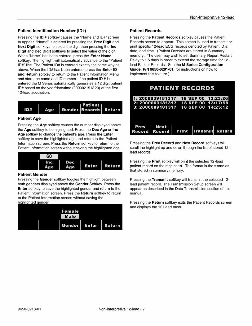
Patient Identification Number (ID#)
Pressing the ID # softkey causes the “Name and ID#” screen to appear. “Name” is entered by pressing the Prev Digit and Next Digit softkeys to select the digit then pressing the Inc Digit and Dec Digit softkeys to select the value of the digit. When “Name” has been entered, press the Enter Name softkey. The highlight will automatically advance to the “Patient ID#” line. The Patient ID# is entered exactly the same way as above. When the ID# has been entered, press the Enter ID and Return softkey to return to the Patient Information Menu and store the name and ID number. If no patient ID # is entered the M Series automatically generates a 12 digit patient ID# based on the year/date/time (200002151320) of the first 12-lead acquisition.
Patient Age Pressing the Age softkey causes the number displayed above the Age softkey to be highlighted. Press the Dec Age or Inc Age softkey to change the patient’s age. Press the Enter softkey to save the highlighted age and return to the Patient Information screen. Press the Return softkey to return to the Patient Information screen without saving the highlighted age.
Patient Gender Pressing the Gender softkey toggles the highlight between both genders displayed above the Gender Softkey. Press the Enter softkey to save the highlighted gender and return to the Patient Information screen. Press the Return softkey to return to the Patient Information screen without saving the highlighted gender.
Patient Records
Pressing the Patient Records softkey causes the Patient Records screen to appear. This screen is used to transmit or print specific 12-lead ECG records denoted by Patient ID #, date, and time. (Patient Records are stored in Summary memory. The user may wish to set Summary Report Restart Delay to 1.5 days in order to extend the storage time for 12-lead Patient Records. See the M Series Configuration Guide, P/N 9650-0201-01, for instructions on how to implement this feature.)
Pressing the Prev Record and Next Record softkeys will scroll the highlight up and down through the list of stored 12 -lead records. Pressing the Print softkey will print the selected 12-lead patient record on the strip chart. The format is the s ame as that stored in summary memory. Pressing the Transmit softkey will transmit the selected 12-lead patient record. The Transmission Setup screen will appear as described in the Data Transmission section of this manual. Pressing the Return softkey exits the Patient Records screen and displays the 12 Lead menu.
OPTION INSERT
9650-0218-01 Non-Interpretive 12-lead - 8
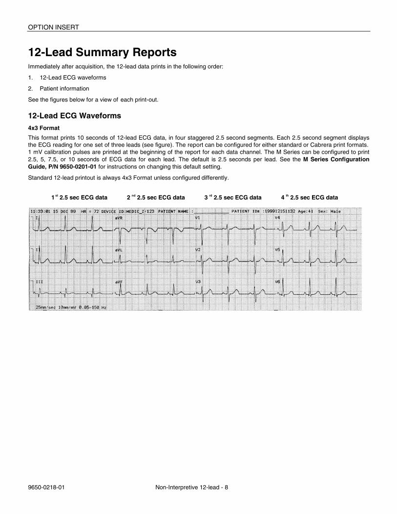
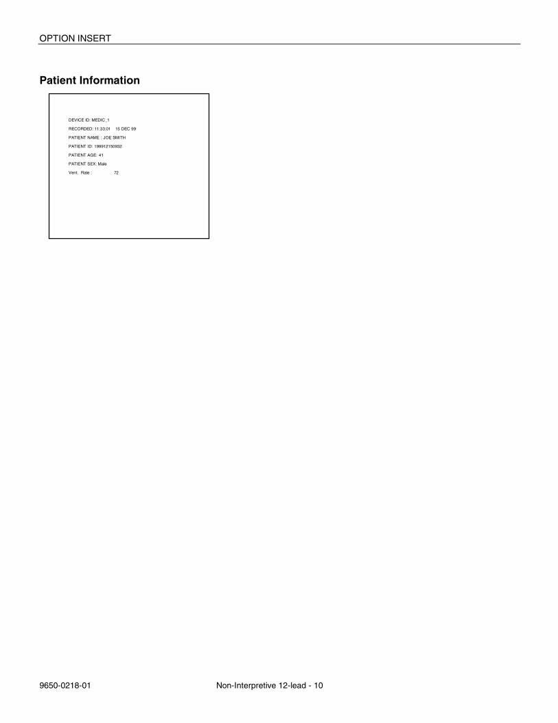
12-Lead Summary Reports Immediately after acquisition, the 12-lead data prints in the following order:
1. 12-Lead ECG waveforms
2. Patient information
See the figures below for a view of each print-out.
12-Lead ECG Waveforms
4x3 Format
This format prints 10 seconds of 12-lead ECG data, in four staggered 2.5 second segments. Each 2.5 second segment displays the ECG reading for one set of three leads (see figure). The report can be configured for either standard or Cabrera print formats. 1 mV calibration pulses are printed at the beginning of the report for each data channel. The M Series can be configured to print 2.5, 5, 7.5, or 10 seconds of ECG data for each lead. The default is 2.5 seconds per lead. See the M Series Configuration Guide, P/N 9650-0201-01 for instructions on changing this default setting.
Standard 12-lead printout is always 4x3 Format unless configured differently.
1 st 2.5 sec ECG data 2 nd 2.5 sec ECG data 3 rd 2.5 sec ECG data 4 th 2.5 sec ECG data
Non-Interpretive 12-lead
9650-0218-01 Non-Interpretive 12-lead - 9
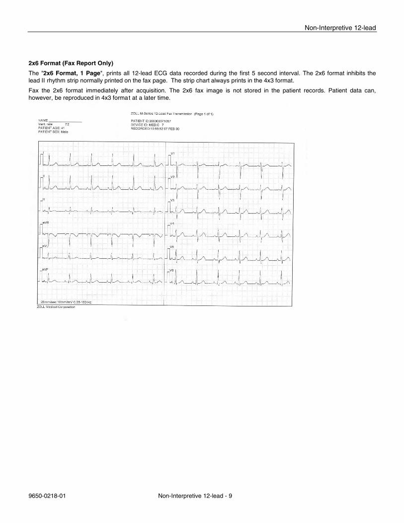
2x6 Format (Fax Report Only)
The "2x6 Format, 1 Page", prints all 12-lead ECG data recorded during the first 5 second interval. The 2x6 format inhibits the lead II rhythm strip normally printed on the fax page. The strip chart always prints in the 4x3 format.
Fax the 2x6 format immediately after acquisition. The 2x6 fax image is not stored in the patient records. Patient data can, however, be reproduced in 4x3 format at a later time.
OPTION INSERT
9650-0218-01 Non-Interpretive 12-lead - 10
Patient Information
DEVICE ID: MEDIC_1
RECORDED: 11:33:01 15 DEC 99
PATIENT NAME : JOE SMITH
PATIENT ID: 199912150932
PATIENT AGE: 41
PATIENT SEX: Male
Vent. Rate : 72
Non-Interpretive 12-lead
9650-0218-01 Non-Interpretive 12-lead - 11
Daily Operational Verification 1. Connect the V-lead cable to the 12-lead cable. 2. Connect the lead wires of the 12-lead cable and V-leads to the patient or 12-lead simulator. If connecting to a patient place ECG
electrodes as indicated in the Electrode Placement Section. 3. Connect the ZOLL 12-lead cable to the connector located on the rear of the M Series. 4. Turn the Selector Switch of the M Series to Monitor. 5. Select a normal sinus rhythm on the Simulator. 6. Cycle through each of the 12 leads by pressing the LEAD button. 7. Verify that good quality, artifact free ECG signals are displayed and stabilized within 10 seconds on your M Series. 8. Verify the “ECG LEAD OFF” message is NOT displayed on the screen. 9. Verify the LOW BATTERY message is NOT displayed on the screen. 10. Verify the filter setting is set for 0.05 – 150 Hz (4x3). 11. Press and hold the RECORDER button for 3 seconds. 12. Verify appropriate ECG signals are printed. See 12-lead Summary Reports Section for reference. 13. Verify accuracy of time and date printed on the strip. 14. Visually inspect ECG Cable snaps for corrosion, particularly on the retaining wire inside the snap.
OPTION INSERT
9650-0218-01 Non-Interpretive 12-lead - 12
Troubleshooting The troubleshooting guide is intended to help you identify and correct problems that arise during operation. If trouble persists after consulting this guide, contact the ZOLL Technical Service Department .
ZOLL Technical Service Department (USA) Phone: (800) 348-9011 (UK) Phone: +44-192-584-6400 (Others) Contact your local ZOLL distributor
Symptom Recommended Action
1. The ECG baseline does not stabilize or the ECG is noisy. Or the following message is displayed: “NOISY ECG”.
1. Verify the electrodes are connected properly to the patient. Reposition the electrodes and/or lead wires to prevent the electrodes from pulling away from the patient.
2. Verify the gel of the electrode is not dry. Check expiration date on the electrode package.
3. Use Silver/Silver Chloride electrodes.
4. Verify patient cable is connected properly and held motionless. Verify that the ECG snaps and connectors are clean.
5. Make sure that the patient is motionless. Support patient’s limbs, if necessary.
6. Stop vehicle while acquiring the 12-lead ECG.
7. Verify correct filter (50 or 60 Hz) is selected in Configuration menu.
8. Inspect ECG cable. Replace if damaged.
9. Change ECG Filter setting to 0.05-40 Hz 4x3 and retry acquisition.
2. “ECG LEAD OFF” or “VX LEAD OFF” 1. Confirm ECG electrode and cable connections.
2. Prepare skin and replace electrodes.
3. Check ECG cable continuity and replace if cable damage is suspect.
4. ECG signal may be temporarily out of range due to recent defibrillator discharge.
3. Unsuccessful transmission to fax (e.g., transmission stops before completion, signal disappears, etc.)
1. Check modem connection (card and extension cable) to M Series.
2. Check modem connection to phone jack or cellular phone.
3. Power cycle cellular phone.
4. Make sure receiving fax is turned on.
5. Check the phone number and attempt to send again.
6. Check the telephone line (landline).
If you are using a cellular phone, be aware that cell signals vary depending on the carrier and area. If you continue to experience problems, switch to a landline.
Non-Interpretive 12-lead
9650-0218-01 Non-Interpretive 12-lead - 13
4. “FAX BUSY” message is displayed. Receiving phone line is being used. The M Series automatically re-transmits until the transmission is successful or the M Series operator presses the Abort softkey.
5. “FAX ERROR” message is displayed.
A dialing problem other than a busy line, no carrier, or no connection occurred.
The M Series automatically re-transmits until the transmission is successful or the M Series operator presses the Abort softkey.
6. “FAX HANGUP” message is displayed.
Receiving phone is not receiving transmission. The M Series automatically re-transmits until the transmission is successful or the M Series operator presses the Abort softkey.
7. “FAX INTERRUPTED” message is displayed.
1. Power cycle M Series unit and retry transmission.
2. Contact ZOLL Technical Service Department.
8. “FAX NO CARRIER” message is displayed.
Receiving phone line is not picking up or the sending modem is experiencing problems. The M Series automatically re-transmits until the transmission is successful or the M Series operator presses the Abort softkey.
If retransmissions fail:
1. Check modem connection (card and extension cable) to M Series.
2. Power cycle cellular phone.
9. “FAX NO DIAL TONE” message is displayed.
1. Check modem connection (card and extension cable) to M Series.
2. Check modem connection to phone jack or cellular phone.
3. Power cycle cellular phone.
10. “MODEM REQUIRED” message is displayed.
No PCMCIA modem card present. Insert PCMCIA modem card in upper slot and repeat transmission.
OPTION INSERT
9650-0218-01 Non-Interpretive 12-lead - 14
APPENDIX A
MODEM AND PHONE SETUP
The M Series with 12-Lead option may include a modem for transmitting 12-lead ECG information to remote locations via landline or cellular phone. This section describes how to connect your M Series unit for phone transmission.
Modem • When included, the M Series with 12-Lead option ships with the Viking Cellular Ready PC Card Modem
installed in the upper PCMCIA slot (domestic units only). • The M Series with 12-Lead option is also available with a Psion WAN Global PC Card, or other approved
GSM card modem (obtained locally for international customers).
Note: Only the upper PCMCIA slot supports modem communication. DO NOT attempt to insert the modem into the lower slot.
Note: The M Series does not support all PCMCIA type modems. Contact ZOLL Technical Support before attempting to use modems other than those specified.
ZOLL Technical Support
Phone: (800) 348-9011
(781) 229-0020
C
B
A
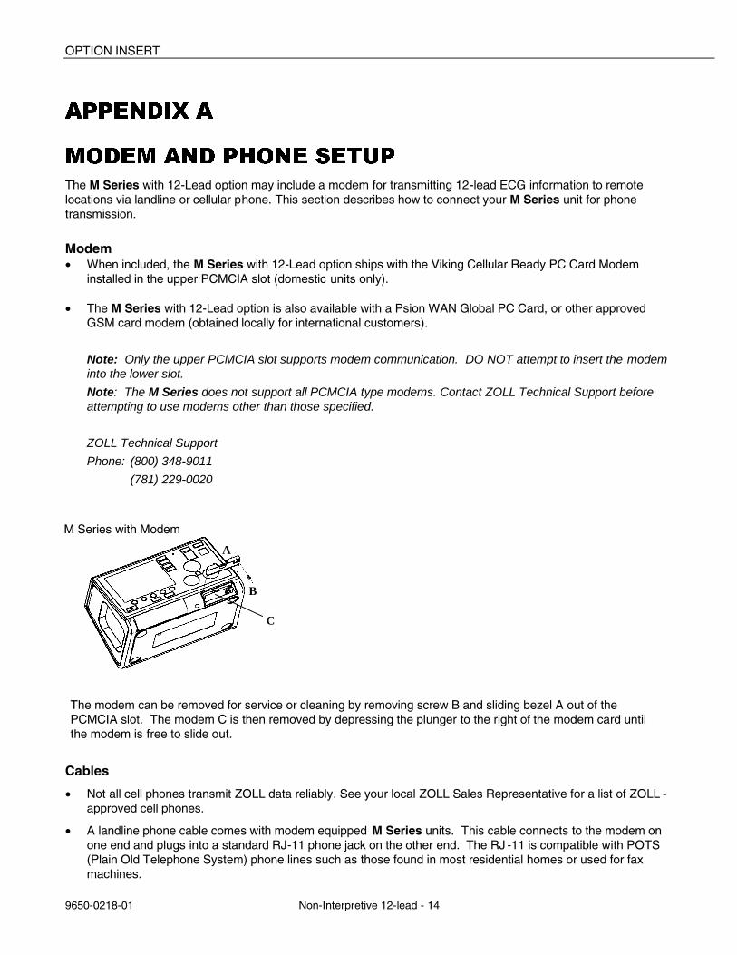
The modem can be removed for service or cleaning by removing screw B and sliding bezel A out of the PCMCIA slot. The modem C is then removed by depressing the plunger to the right of the modem card until the modem is free to slide out.
Cables • Not all cell phones transmit ZOLL data reliably. See your local ZOLL Sales Representative for a list of ZOLL -
approved cell phones.
• A landline phone cable comes with modem equipped M Series units. This cable connects to the modem on one end and plugs into a standard RJ-11 phone jack on the other end. The RJ -11 is compatible with POTS (Plain Old Telephone System) phone lines such as those found in most residential homes or used for fax machines.
M Series with Modem
Non-Interpretive 12-lead
9650-0218-01 Non-Interpretive 12-lead - 15
• The modem in the M Series is compatible with certain AMPS (analog) or dual-mode cellular phones in the U.S.A., and with certain GSM cellular phones in Europe, depending on modem model. Each model phone requires a specific modem- to-cell phone interconnect cable. Cables may be purchased through The Supply Net, Inc. in Valley Cottage, NY:
www.thesupplynet.com Phone: (800) 826-0279 Fax: (914) 267-2420
International customers should contact their local ZOLL representatives for their local supplier of cellular phone cables and upgrade kits.
• For connection to a Motorola 3-Watt “Bag Phone” or vehicle-mounted phone, ZOLL recommends using the included landline cable along with Motorola’s Cellular Connection, Model S1936D. This device is also known as a “dial tone generator” and is used to interface the RJ11 landline connector with the 3 -Watt cellular phone. The Motorola Model S1936D along with support for vehicle-mounted phones is available through AirDesk, Inc. Mobile Quest in Warminster, PA:
www.mobilequest800airdesk.com Phone: (800) 882-1288 M-F 8:30 AM – 5:30 PM EST (800) 206-6108 M-F 5:30 PM – 8:00 PM EST Fax: (215) 734-8000
• The M Series with Viking Cellular Ready PC Card modem may be used with ZOLL’s ruggedized cellular ready modem extension cable. This cable is available either integrated into the Xtreme Pack II or standalone as follows: • P/N 8000-0744 Xtreme Pack II with rear pouch and cellular ready modem extension cable. • P/N 8000-0745 Xtreme Pack II with rear and side pouches and cellular ready modem extension cable. • P/N 8000-0086 Cellular ready modem extension cable, standalone. • P/N 7777-0129 Cellular ready modem extension cable upgrade kit for existing Xtreme Pack II.
• To reduce wear on the connector, keep the phone cable plugged into the extension cable when the extension cable is in use. In this manner, the user would primarily disconnect from the phone at the phone end of the cable.
• When first connecting the phone cable to the modem or modem extension cable, note the orientation of the connectors for future reference. The connectors are keyed and only mate in one orientation.
Configuring Phone Numbers
• Please see the ZOLL M Series Configuration Guide, P/N 9650-0201-01, for instructions on how to program automatic-dial phone numbers into the M Series unit.
• Manual phone number entry is described in the Data Transmission section of this document.
Configuring the Modem for Cellular Phones
• The Viking Cellular Ready PC Card modem comes pre-configured for landline and certain Nokia or Motorola cellular phones. If a different cellular phone is to be used, remove the modem from the M Series unit. Insert the modem into a Windows laptop or PC with PCMCIA slot. Download the modem driver corresponding to your cellular phone from www.vikingcomponents.com. Consult ZOLL Technical Support for further information.
• The Psion WAN Global PC Card modem comes pre-configured for landline. If a GSM cellular phone is to be used, purchase the GSM Upgrade Pack from Psion. Remove the modem from the M Series unit and follow the instructions included in the Upgrade Pack.
OPTION INSERT
9650-0218-01 Non-Interpretive 12-lead - 16
CAUTION
• Data transmission via cellular phones can be less reliable than transmission via landline connections. A strong signal and stationary transmission will improve the transmission’s success rate. Follow the directions provided with your cellular phone.
• Many hospitals prohibit the use of cellular phones on their premises. Please abide by local rules and regulations.
TRANSMISSION SPECIFICATIONS
Fax • Group 3 Facsimile • FAX Software Interfaces
Class 2, EIA-TR29.2 Class 1
Telephone Company Requirements The following regulations apply to modems used within the United States and Canada.
FCC Regulations
• The FCC has established rules that permit this device to be directly connected to the telephone network, using a standardized jack. Do not use this equipment on a party line or coin line.
• Malfunctioning equipment may cause damage to the telephone network. If this device is not functioning properly, disconnect it until the problem has been determined and the device has been repaired. Otherwise, the telephone company may disconnect service temporarily.
• The modem card is a non-serviceable/repairable item. It is the responsibility of the user to report the need for any service to the device to ZOLL Medical Corporation.
• If you encounter any problems with your telephone after installing any new device, disconnect it from the telephone line to see if the device is the source of the problem.
• The telephone company may make changes to its technical operations and procedures. If such changes affect the compatibility or use of this device, the telephone company is required to provide adequate notice of the changes.
Phone Company Requests
If the telephone company requests information about the equipment connected to their lines, inform them of:
1. The telephone number to which the device is connected.
2. The ringer equivalence number (REN), which is found on the FCC sticker attached to the modem. The REN determines how many devices may be connected to the same telephone line. If too many devices are attached, they may not ring properly. In most areas, the sum of the ringer equivalence numbers of all devices connected to the same line should not exceed five.
3. The USOC telephone jack required (RJ11, RJ41, or RJ45).
4. The FCC registration number, which is found on the FCC sticker attached to the modem.
Non-Interpretive 12-lead
9650-0218-01 Non-Interpretive 12-lead - 17
Interference
WARNING
Changes or modifications to this unit not expressly approved by the party responsible for compliance could void the user's authority to operate the equipment.
This equipment generates, uses, and can radiate radio frequency energy and, if not installed and used in accordance with the instructions, may cause harmful interference to radio communications. Operation of this equipment in a residential area is likely to cause harmful interference, in which case the user will be required to correct the interference at his own expense. However, there is no guarantee that interference will not occur in a particular installation. If this equipment does cause harmful interference to radio or television reception, which can be determined by turning the equipment off and on, the user is encouraged to try to correct the interference by one or more of the following measures:
• Re-orient the receiving antenna.
• Relocate the receiving antenna and/or equipment away from the modem.
• Relocate the modem away from the receiving antenna and/or equipment.
• Plug the modem into a different outlet so that the modem and the receiving equipment are on different electrical circuits.
If none of these actions resolves the problem, consult your distributor or an experienced radio/television technician for additional suggestions.
FCC Rules and Regulations - Part 68
This equipment complies with Part 68 of the FCC Rules. On the back of the modem card is a label that contains, among other information, the FCC Registration Number and Ringer Equivalency Number (REN) for this equipment. You must, upon request, provide this information to your telephone company.
The REN is useful to determine the quantity of devices you may connect to your telephone line and still have all those devices ring when your telephone number is called. In most but not all areas, the sum of the RENs of all devices connected to one line should not exceed five (5.0). To be certain of the number of devices you may connect to your line, as determined by the REN, you should contact your local telephone company to determine the maximum REN for your calling area.
If your telephone equipment causes harm to the telephone network, the telephone company may discontinue your service temporarily. If possible, they will notify you in advance. But if advance notice is not practical, you will be notified as soon as possible. You will be informed of your right to file a complai nt with the FCC.
Your telephone company may make changes in its facilities, equipment, operations or procedures that could affect the proper functioning of your equipment. If they do, you will be notified in advance to give you an opportunity to maintain uninterrupted telephone service.
If you experience trouble with this telephone equipment, please contact ZOLL Medical Corporation, for information on obtaining service or repairs. The telephone company may ask that you disconnect this equipment from the network until the problem has been corrected or until you are sure that the equipment is NOT malfunctioning.
There are no user serviceable parts contained in this equipment.
This equipment may not be used on coin service provided by the telephone company. C onnection to party lines is subject to state tariffs.
OPTION INSERT
9650-0218-01 Non-Interpretive 12-lead - 18
Shielded Cables
The use of any cable other than the shielded type will allow your system to emit more radio frequency interference than the FCC limits, thereby increasing the likelihood of inter ference. Therefore, in order to comply with the FCC regulations, it is necessary that you use good quality shielded cables with your installation.
Canadian Requirements
The Industry Canada, formerly the Canadian Department of Communications, label identif ies certified equipment. This certification means that the equipment meets certain telecommunications network protective, operational, and safety requirements. The Department does not guarantee the equipment will operate to the user's satisfaction.
Before installing this equipment, users should ensure that their local telecommunications company permits connecting it to their facilities. The equipment also must be installed using an acceptable method of connection. In some cases, the company's inside wiring associated with single line, individual service may be extended by means of a certified connector assembly (telephone extension cord). The customer should be aware that compliance with the above conditions may not prevent degradation of service in some sit uations.
Repairs to certified equipment should be made by an authorized Canadian maintenance facility designated by the supplier. Any repairs or alterations made by the user to this equipment or equipment malfunctions may give the telecommunications company cause to request the user to disconnect the equipment.
Users should ensure, for their own protection, that the electrical ground connections of the power utility, telephone lines, and internal metallic water pipe system, if present, are connected togethe r. This precaution may be particularly important in rural areas.
CAUTION:
Users should not attempt to make such connections themselves, but should contact electric inspection authorities or electricians, as appropriate.
To prevent overloading, a Load Number (LN) has been assigned to each terminal device to denote the percentage of the total load to be connected to a telephone loop which is used by the device. The termination on a loop may consist of any combination of devices subject only to the requirement that the total number of devices not exceed one hundred.